Embed Size (px)
Citation preview
5th International Symposium on Hydraulic Structures Brisbane, Australia, 25-27 June 2014 Hydraulic Structures and Society: Engineering Challenges and Extremes ISBN 9781742721156 - DOI: 10.14264/uql.2014.11
Hydraulics of stepped weirs and dam spillways: engineering challenges, labyrinths of research
J. Matos1 and I. Meireles2
1Department of Civil Engineering, Architecture and Georesources Instituto Superior Técnico, Universidade de Lisboa
Av. Rovisco Pais, Lisboa 1049-001 PORTUGAL
1Department of Civil Engineering University of Aveiro
Campus de Santiago, Aveiro 3810-193 PORTUGAL
E-mail: [email protected]
Abstract: Stepped weirs and dam spillways have been increasingly used for handling flood releases, due to their inherent benefits, particularly those related to energy dissipation. Among the diversity of construction techniques for which a stepped chute turns out to be an attractive solution, the popularity of roller compacted concrete placement on new and rehabilitated dams has prompted interest in researching the hydraulics of stepped spillways, for medium to large unit discharges. In this paper, some main applications of stepped chutes are briefly described, with a particular focus on recent engineering challenges on spillways over concrete gravity or RCC dams, questions raised and some answers proposed. Some peculiar, eventually paradoxical aspects of the non-aerated and self-aerated skimming flows on steeply sloping chutes are addressed, in light of the self-aerated flow on smooth spillways. Later, a brief review of possible future research topics in this captivating field of research is included. Keywords: Stepped spillways, hydraulic modelling, skimming flow, cavitation, air entrainment.
1. INTRODUCTION
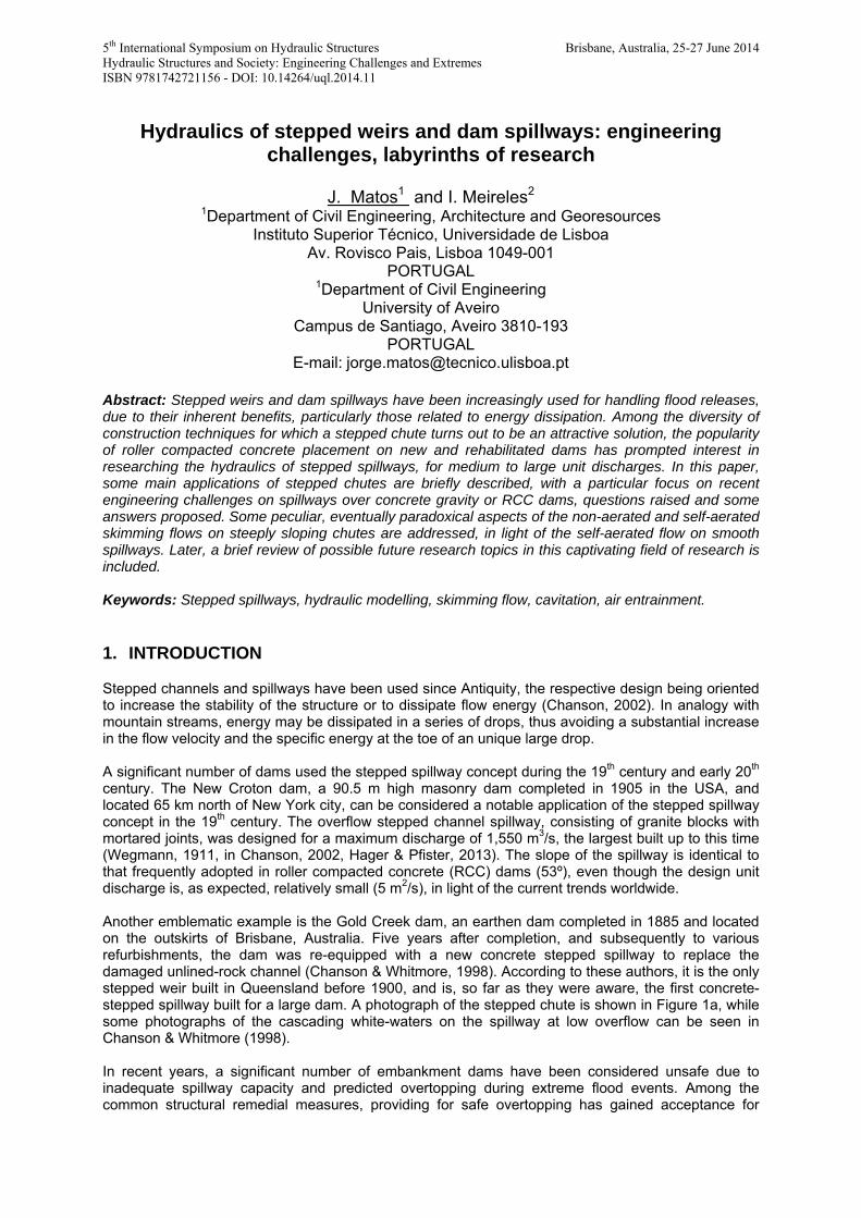
Stepped channels and spillways have been used since Antiquity, the respective design being oriented to increase the stability of the structure or to dissipate flow energy (Chanson, 2002). In analogy with mountain streams, energy may be dissipated in a series of drops, thus avoiding a substantial increase in the flow velocity and the specific energy at the toe of an unique large drop. A significant number of dams used the stepped spillway concept during the 19th century and early 20th century. The New Croton dam, a 90.5 m high masonry dam completed in 1905 in the USA, and located 65 km north of New York city, can be considered a notable application of the stepped spillway concept in the 19th century. The overflow stepped channel spillway, consisting of granite blocks with mortared joints, was designed for a maximum discharge of 1,550 m3/s, the largest built up to this time (Wegmann, 1911, in Chanson, 2002, Hager & Pfister, 2013). The slope of the spillway is identical to that frequently adopted in roller compacted concrete (RCC) dams (53º), even though the design unit discharge is, as expected, relatively small (5 m2/s), in light of the current trends worldwide. Another emblematic example is the Gold Creek dam, an earthen dam completed in 1885 and located on the outskirts of Brisbane, Australia. Five years after completion, and subsequently to various refurbishments, the dam was re-equipped with a new concrete stepped spillway to replace the damaged unlined-rock channel (Chanson & Whitmore, 1998). According to these authors, it is the only stepped weir built in Queensland before 1900, and is, so far as they were aware, the first concrete-stepped spillway built for a large dam. A photograph of the stepped chute is shown in Figure 1a, while some photographs of the cascading white-waters on the spillway at low overflow can be seen in Chanson & Whitmore (1998). In recent years, a significant number of embankment dams have been considered unsafe due to inadequate spillway capacity and predicted overtopping during extreme flood events. Among the common structural remedial measures, providing for safe overtopping has gained acceptance for
existing small embankment dams, which constitutes the majority as regards recent ICOLD statistics of dam failures (Berga, 1995). A remarkable study of stepped spillways was carried out by Gaussmann & Madden (1923) on the Gilboa dam in New York (also in Hager & Pfister, 2013). The masonry part of the dam, with a maximum height of 49 m and formed by large, 6 m high, steps, was believed to be the highest overfall dam constructed at the time (Gaussmann & Madden, 1923). Experiments were carried out on three distinct scales, 1:50, 1:20 and 1:8, under a prototype approach flow head approximately equal to 0.9 m. After such impressive study, a limited number of research studies were conducted on the hydraulics of stepped spillways until the 1980’s (e.g., Essery & Horner, 1978, Stephenson, 1979). In early 1980’s, a model study was conducted to investigate the feasibility of a stepped spillway for Upper Stillwater dam, the first roller compacted concrete dam constructed by the U.S. Bureau of Reclamation and also the first stairstepped spillway of its size in the USA (Young, 1982) – Figure 1b.
(a) (b)
Figure 1 – Examples of emblematic stepped spillways built in the 19th and 20th centuries: (a) Gold Creek dam, Australia, earthen dam with a concrete stepped waterway (completed in 1885, stepped
waterway built in 1890) (Photograph taken on July 2011); (b) Upper Stillwater dam, USA, RCC gravity dam with incorporated spillway, finished in 1987 (Courtesy of P. Guedes de Melo)
During the period 1985-2000, and according to Chanson (2000), the international database Science Citation Index (The Web of Science) had listed 14 papers and 21 discussions and closures on stepped-spillway, or stepped chute, hydraulics, all but two having been published between 1990 and 2000; further one book (Chanson, 1994) had also been listed in the database Global Books in Print. Since then, another book was published (Chanson, 2002) and a significant number of design or research-oriented studies were conducted worldwide, either experimental, numerical or composite studies: i.e., a “big-bang” in research! In this paper, after a general introduction on the topic, particular focus is given on the hydraulics of stepped spillways over steep gravity dams for moderate to high unit flow rates. Some peculiar, eventually paradoxical aspects of research, are addressed, such as: can the self-aerated flow on stepped spillways for high flow rates, be similar to that found on conventional (smooth) spillways, and modeled with similar tools? On the other hand, can the depth-averaged air concentration be significant in the apparently smooth, “non-aerated” flow region? Can the total (entrained and entrapped) air decrease along the chute? Can the mean water velocity increase when decreasing the flow rate, for an identical location on the same chute? Can cavitation occur, without leading to damage on the stepped surfaces? Finally, this study is concluded with an assessment of future research topics in such a captivating field.
2. STEPPED SPILLWAYS: EXAMPLES OF APPLICATION, ENGINEERING CHALLENGES
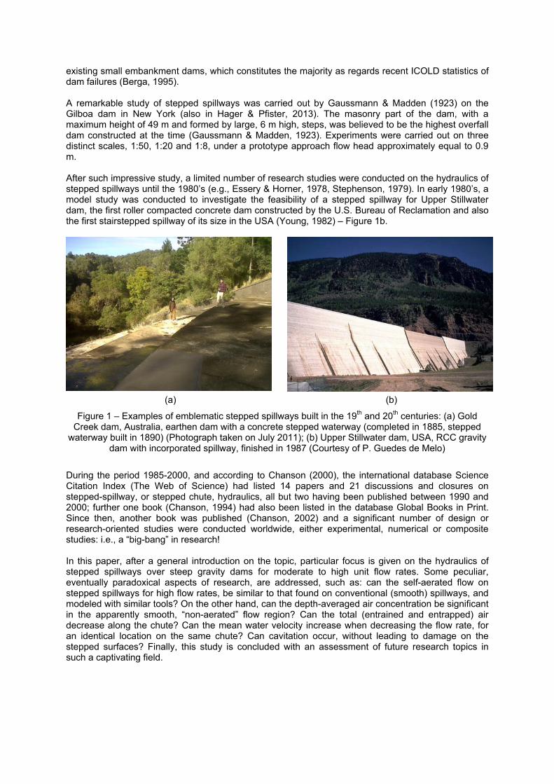
In addition to early stepped spillways that were built in masonry, some major concrete or unlined rock stepped spillways were built in the second half of the 20th century. Relevant examples include the Clywedog dam, UK, 1968 (concrete), the Dartmouth dam, Australia, 1977 (unlined rock), and La Grande 2 dam, Canada, 1982 (unlined rock). Timber stepped weirs were also a common design, and several structures are still used after more than half-century, such as the notable case of the Cunningham weir, which was able to sustain very large overflows (Chanson, 1998). Photographs of air-water flows at the imposing Dartmouth and the La Grande 2 dam spillways can be seen in Chanson (2002). Recently, new techniques (e.g., gabions, pre-cast concrete blocks, and roller compacted concrete, RCC), or diversity of applications (e.g., improving water quality on projects where low dissolved oxygen or highly supersaturated conditions exist) have greatly renewed the interest in stepped spillways. The 1980’s can be considered a turning point decade regarding the rate of application of stepped spillways, namely on large dams. At the end of 1986, there were only 15 completed RCC dams in the world, namely six in the USA, two in each of South Africa, Australia and Japan, and one in each of Brazil, Spain and China (Dunstan, 1996). Since then, RCC dams have gained wide acceptance throughout the world due to their economic advantage combined with their long-term safety. Even though gravity dams constitute the majority of RCC dams, the technique was also applied in arch-gravity dams, such as the pioneering Knellpoort and Wolwedans dams in South Africa, concluded in 1988 and 1990, respectively. Based on U.S. Bureau of Reclamation considerations and initial model study findings for the Upper Stillwater dam, Monksville dam, also in the USA, was the first RCC dam constructed with a stepped spillway. Hydraulic model studies were performed during the design of the Monksville dam to provide information to confirm the adequate size of steps, the smooth transition geometry from the ogee crest to the stepped chute, and the elimination of terminal energy dissipation (Sorensen, 1985, Ditchey & Campbell, 2000). Even though a considerable number of RCC gravity dams include a stepped spillway on its downstream face, such as the Pedrógão dam in Portugal, this concept may still be economically attractive using conventional concrete, such as Vila Viçosa and Olgas dams, also in Portugal (Figure 2). In some cases, such as the Vila Viçosa dam spillway, aesthetic reasons, namely the proximity of a small water cascade, were determinant for the selection of the stepped face. Table 1 list some concrete and RCC dams incorporating a stepped spillway on the downstream face. Many of the dams have incorporated a stepped spillway with the benefit of hydraulic model investigations. An extensive list of prototype applications and physical model studies are included in Chanson (2002). The most common form of spillway used on RCC dams has been the uncontrolled crest, in result of the economies inherent to this form of structure and their ease of construction. Nevertheless more recent RCC dams have been designed and constructed with gated spillways. After an initial period where the discharge per unit length was in general limited to 20 m2/s, significantly larger unit discharges have been considered more recently, such as for Pedrógão dam (unit design discharge q=40 m2/s), Shuidong dam (q=100 m2/s), or Dachaoshan dam (q=165 m2/s) (Table 1). As far as it can be assessed, the performance of stepped spillways on RCC or concrete gravity dams dams in service has been satisfactory, the steps being intact or in good operational order. Spillings have been experienced on several stepped dam spillways (e.g., M’Bali dam in Central African Republic, Upper Stillwater dam in the USA, Trigomil dam in Mexico, De Mist Kraal, Zaaihoek and Wolwedans dams in South Africa, Dona Francisca dam in Brazil, Hinze and Paradise dams in Australia, Pedrógão, and Olgas dams in Portugal). A major prototype experience was however that of the Shuidong dam in China. Shortly after beginning the operation, the dam experienced a large flood (nearly 100 year return period). The flood discharge
reached 5397 m3/s, which corresponds to a unit flow of 90 m2/s, fairly close to the design value. During the event, visual observation of the site was made and no abnormal phenomena occurred. Subsequent examination showed that the steps remained intact (He & Zeng, 1995). In addition to gravity or arch-gravity RCC dams, the RCC protection technique has gained acceptance for overtopping protection of embankment dams, particularly in the USA (Bass, 2000, McLean & Hansen, 1993, Chanson, 2002, 2013a, Frizell, 2006, Hunt et al, 2008). Typical examples of embankment dam overtopping protection with RCC are shown in Figure 3. Although most of the RCC stepped overlays for overtopping protection have not yet been subjected to large flows, close to the design value, some have experienced significant spills (e.g., Ocoee 2 dam, USA), while others have passed low flows. A review of the performance of several projects is included in McLean & Hansen (1993).
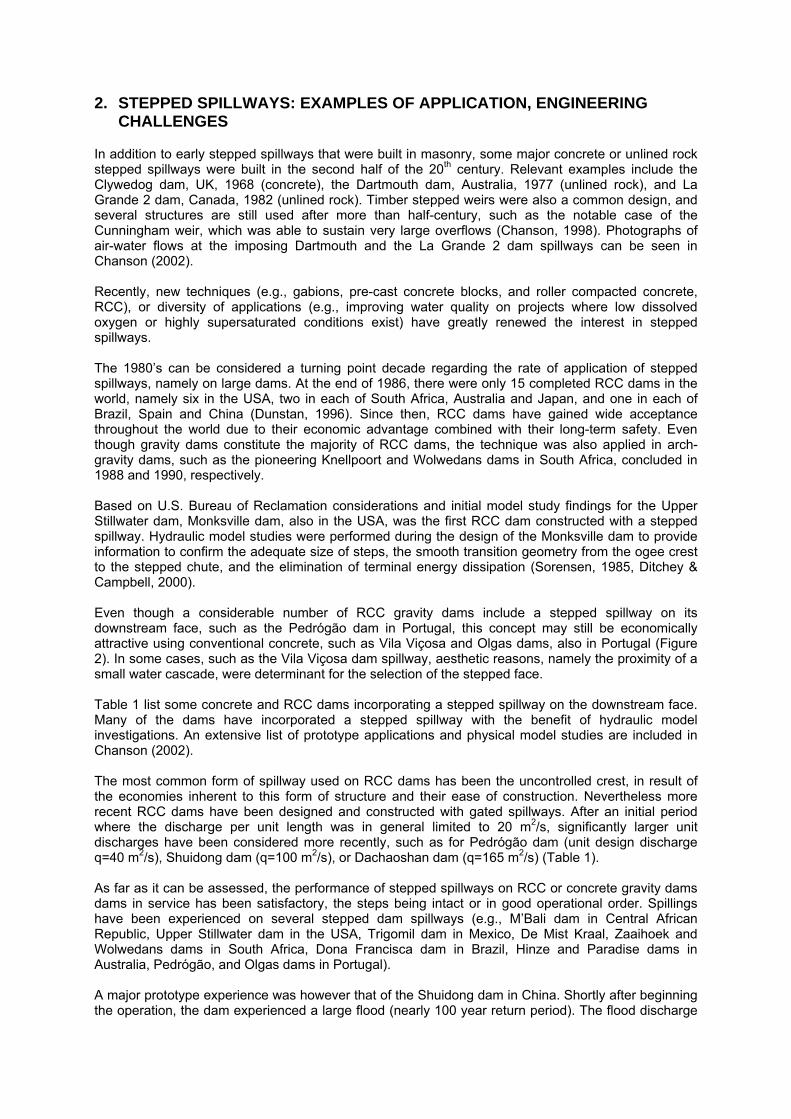
Table 1 - Stepped spillways over concrete or RCC dams: some typical applications
Dam Ref. Dam
height
(m)
Chute
height
(m)
Chute
slope
(deg.)
Chute
width
(m)
Step
height
(m)
Design
unit
disch.
(m2/s)
Remarks
Boquerón, Spain, 1997
ME, SJ1
58 46 54 16 1.2 17.8
De Mist Kraal Weir, South Africa, 1986
GO, GE1, GE2
30 18.5 59 210 1.0 10.3 qpeak = 3 m2/s
Dachaoshan, China(1)
GU 111 55 70
1.0 165 Flaring pier gate qcheck = 250 m2/s
Dona Francisca, Brazil, 2001
SG 50.5 43,5 53 335 0.6 32
La Puebla de Cazalla, Spain, 1991
EM, ME 71 58.2 51 18 0.9 9.0 Chamfering of outer step edges.
Les Olivettes, France, 1987
GO 36 31.5 53 40 0.6 6.6
Monksville, USA, 1987
SO 48 36.6 52 61 0.6 9.3
Nakasujigawa, Japan, 1998
HS 71.6 64.1 55 175(3) 0.75 6.6(3) Converging side walls. Chamfering of outer step edges
New Victoria, Australia, 1993(2)
WA 52 72; 51 130 0.6 5.4
Olgas, Portugal, 2006
SA 34.5 27.6 51 23.6(3) 0.9 8.3(3) Converging side walls
Pedrógão, Portugal, 2005
SR, IN 43 28.8 51 301 0.6 39.9
Shuidong, China, 1994
HZ 62 38.2 60 60 0.9 100.2 Flaring pier gate qcheck =138.7 m2/s qpeak = 90 m2/s
Stagecoach, USA, 1988
FR, SJ2
46 42.7 51 16.8 0.6 3.6
Upper Stillwater, USA, 1987
HO 88 61 72; 59 183.0 0.6 11.4
Wolwedans, South Africa, 1990
GE1, GE2
70 62.9 63 77(3) 1.0 12.4(3) Curved spillway. qpeak = 4 m2/s
Note: (1) Field testing (I: Q=3896 m3/s; II: 6173 m3/s); (2) in Chanson (2002); (3) at spillway crest. EM – Elviro & Mateos (1992); FR – Frizell (1992); GE1 – Geringer (1995); GE2 – Geringer & Officer (1995); GO - Goubet (1992); GU – Guo et al (2003); HO - Houston (1987); HS – Hakoishi & Sumi (2000); HZ – He & Zeng (1995); IN – INAG website: http://cnpgb.inag.pt/gr_barragens/gbportugal/Pedrogao.htm (on Jan. 6, 2014); ME – Mateos & Elviro (2000); SO – Sorensen (1985); WA – Wark et al (1991); SA – Samora & Afonso (2006); SG – Sanagiotto et al (2012); SJ1 – Sánchez-Juny (2001); SJ2 – Sánchez-Juny et al (1998); SR – Silva & Ramos (2001).
(a)
(b)
(c)
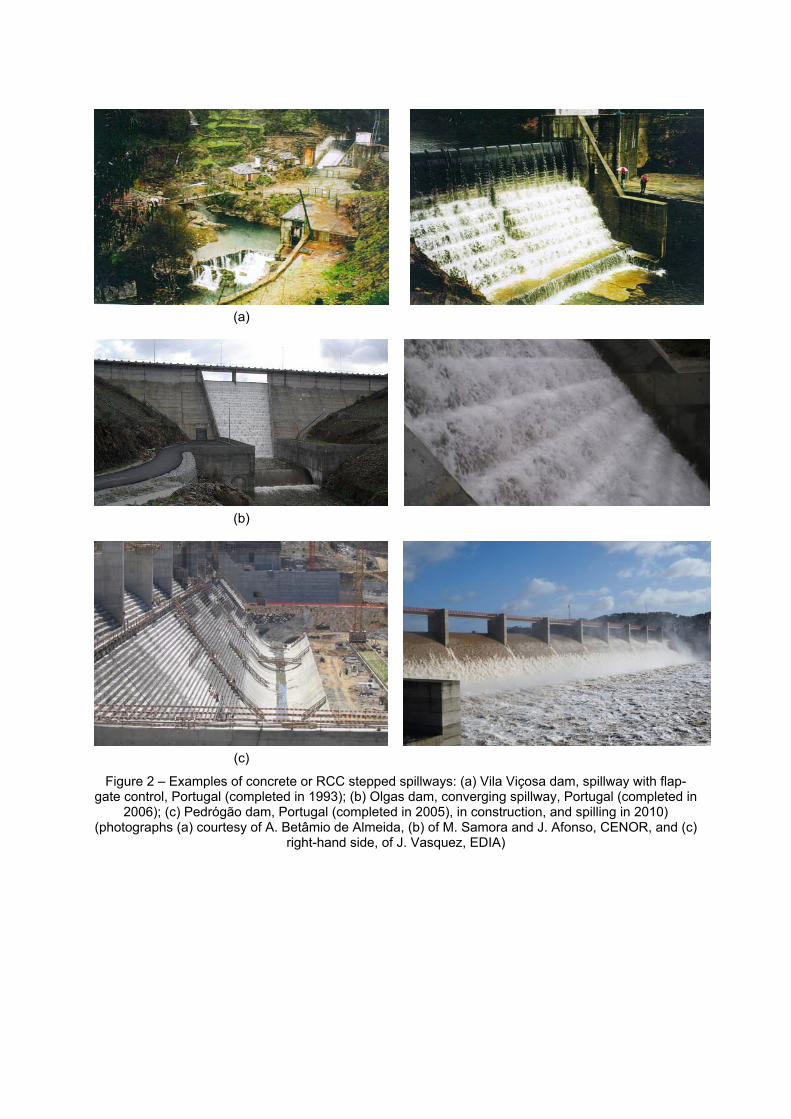
Figure 2 – Examples of concrete or RCC stepped spillways: (a) Vila Viçosa dam, spillway with flap-gate control, Portugal (completed in 1993); (b) Olgas dam, converging spillway, Portugal (completed in
2006); (c) Pedrógão dam, Portugal (completed in 2005), in construction, and spilling in 2010) (photographs (a) courtesy of A. Betâmio de Almeida, (b) of M. Samora and J. Afonso, CENOR, and (c)
right-hand side, of J. Vasquez, EDIA)
(a) (b)
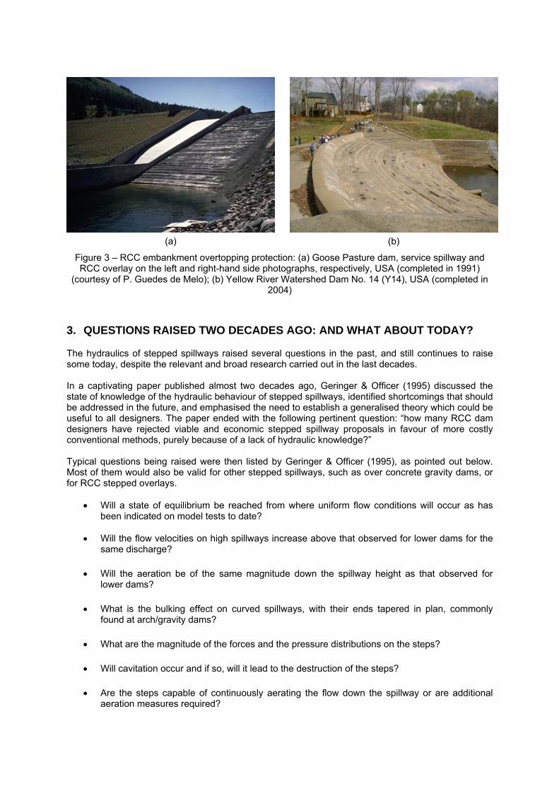
Figure 3 – RCC embankment overtopping protection: (a) Goose Pasture dam, service spillway and RCC overlay on the left and right-hand side photographs, respectively, USA (completed in 1991)
(courtesy of P. Guedes de Melo); (b) Yellow River Watershed Dam No. 14 (Y14), USA (completed in 2004)
3. QUESTIONS RAISED TWO DECADES AGO: AND WHAT ABOUT TODAY?
The hydraulics of stepped spillways raised several questions in the past, and still continues to raise some today, despite the relevant and broad research carried out in the last decades. In a captivating paper published almost two decades ago, Geringer & Officer (1995) discussed the state of knowledge of the hydraulic behaviour of stepped spillways, identified shortcomings that should be addressed in the future, and emphasised the need to establish a generalised theory which could be useful to all designers. The paper ended with the following pertinent question: “how many RCC dam designers have rejected viable and economic stepped spillway proposals in favour of more costly conventional methods, purely because of a lack of hydraulic knowledge?” Typical questions being raised were then listed by Geringer & Officer (1995), as pointed out below. Most of them would also be valid for other stepped spillways, such as over concrete gravity dams, or for RCC stepped overlays.
Will a state of equilibrium be reached from where uniform flow conditions will occur as has been indicated on model tests to date?
Will the flow velocities on high spillways increase above that observed for lower dams for the same discharge?
Will the aeration be of the same magnitude down the spillway height as that observed for lower dams?
What is the bulking effect on curved spillways, with their ends tapered in plan, commonly found at arch/gravity dams?
What are the magnitude of the forces and the pressure distributions on the steps?
Will cavitation occur and if so, will it lead to the destruction of the steps?
Are the steps capable of continuously aerating the flow down the spillway or are additional aeration measures required?
What are the actual flow patterns occurring on the steps?
Will other forces imposed on the steps lead to their eventual destruction? If so, what operational life span can be expected?
What energy dissipation can be expected at the toe of the dam under various discharges?
What maximum unit discharge for which a stepped spillway can be designed to ensure a problem-free operational life?
Experimental work done on stepped spillways has been limited to small scale models. What kind of results will be obtained from a 1:15 scale model which is considered to be the order of scale that will provide acceptable results on the hydraulic action of steps?
In spite of the broad and significant research conducted worldwide in the last two decades, with recognized advances in the understanding of stepped spillway hydraulics, both the scientific and technical hydraulic communities were not able to find appropriate responses to some of the questions raised by Geringer & Officer (1995). The response to the fist apparently basic question, related to a state of equilibrium be reached down the chute slope, is still today not fully consensual. Even though uniform flow conditions seem to have be attained in various model studies, for given chute configuration and flow conditions (e.g., Christodoulou, 1999, Pegram et al, 1999, Boes and Hager 2003a,b, André, 2004, Relvas & Pinheiro, 2008, Bung, 2011, Pfister & Hager, 2011, Takahashi & Ohtsu, 2012), it has also been suggested that flow resistance in skimming flows is not an unique function of the flow rate and stepped chute geometry, and it has been hypothesized that the form drag process may present several modes of excitation that are functions of the inflow conditions (Chanson, 2006, Felder & Chanson, 2009a). The second, third and tenth questions seem to be more consensual today. In fact, for identical discharge, various studies indicate a trend of increasing velocity down the steep chute, even though the mean velocity may decrease locally, due to the undulation of the free surface (e,g., Matos, 2000, Chanson, 2002, Boes & Hager 2003b, Renna, 2004, Gonzalez & Chanson, 2007, Bung, 2011, Meireles, 2011). For high dams, in the developing flow region downstream of the inception of air entrainment, the magnitude of aeration varies down the spillway height (e.g., Chamani and Rajaratnam, 1999, Matos, 2000, Boes & Hager, 2003a, Pfister & Hager, 2011); for lower dams, in contrast, the inception of air entrainment may even not take place for high flow rates (e.g., Chanson, 2002, Hunt & Kadavy, 2010, Meireles et al, 2012). Various studies have addressed the energy dissipation on stepped spillways, and simple methods have been proposed for estimating the energy dissipation or the residual energy (e.g., Pegram et al, 1999, Chanson 2002, Matos, 2002, Boes & Hager, 2003b, Simões et al, 2008, Takahashi & Ohtsu, 2012). The bulking effect on curved spillways (point four), is a topic that should require experimental investigation. However, various design or research oriented studies have already been conducted on converging stepped spillways, either for typical embankment dam slopes (e.g., Frizell, 1990, André et al, 2005, Hunt et al, 2008), or for RCC or concrete gravity dams (e.g., Hanna & Pugh, 1997, Hakoishi & Sumi, 2000, Willey et al, 2010). With regards to the magnitude of the forces and the pressure distributions on the steps (fifth query), some relevant information has been published in the last decades, namely by Gaston (1995), Baker (1992), Sánchez-Juny (2001), Sánchez-Juny et al (2008), André (2004), Amador (2005), Amador et al (2009), Gomes (2006), Gomes et al (2006), Relvas (2008) and Relvas & Pinheiro (2011), among others. Recent studies suggest that cavitation may occur on skimming flow over steeply sloping stepped chutes (point six), such as those by Gomes (2006) and Amador (2005), or Amador et al (2009), from the analysis of the extreme negative pressure field on the step faces, or by Frizell et al (2013), using laboratory experiments in a specialized reduced ambient pressure chamber. However, in spite of significant flood releases which have already occurred in some large dams (e.g., Shuidong and Dachaoshan RCC dams in China, Dona Francisca dam in Brazil), cavitation damage has not been
reported, nor precise information has been found on the operational life span that can be expected on stepped spillways. For high unit flow rates on large dams (query seven), the length of the non-aerated flow region may be significant, with high velocities being reached on the chute. Under such circumstances, additional aeration measures may possibly be required in order to avoid cavitation damage, such as by means of bottom aerators (Pfister et al, 2006, Zamora et al, 2008). The flow patterns occurring on the steps (question eight) have been studied qualitatively (e.g., Matos et al, 1999), and quantitatively, including experimental data obtained in the step cavities, in the non-aerated flow region (e.g., Amador, 2005, Amador et al, 2006a,b), and also in the aerated flow region, namely by Boes (2000a), Gonzalez (2005) and Felder (2013); however, a thorough understanding of the three-dimensional flow patterns on the step cavities is still lacking. In spite of the information recently gained on the actions imposed by the flow on the step surfaces (questions nine; eleven), in particular on steeply sloping chutes, as well as the possible occurrence of cavitation, a definite answer has not been given so far on the maximum unit discharge for which a stepped spillway can be designed to ensure a problem-free operational life. In addition to small scale model studies (point twelve), prototype and quasi-prototype tests have also been conducted in recent years, in particular for stepped spillways typical of those found on embankment dams (Ruff & Frizell, 1994, Gaston, 1995, Ward, 2002). Even though such studies were able to provide important findings, including those related to self-similarity (e.g., air concentration and velocity profiles, main flow properties down the chute, namely at equilibrium), a precise evaluation of scale effects was not provided. Some relevant filed testing was also carried out on major stepped spillways, namely in China (e.g., Dachaoshan dam). However, the particular spillway configuration (e.g., including flaring-pier gates and 2 m high flip bucket next to the end of the piers), cannot allow a generalization of the obtained results to other conventional chute configurations, namely with regard to the maximum unit discharge to ensure a cavitation damage-free operational life. Some important studies have been also developed from model families of fairly large-size stepped chutes, providing useful information on the limiting scale factors to prevent significant scale effects, with a focus on air concentration (void fraction) and velocity (e.g., Boes, 2000a,b, Chanson & Gonzalez, 2005), or even on detailed bubble and turbulence flow properties (e.g., Chanson and Toombes, 2002b, Felder & Chanson 2009b, Felder, 2013). A more general review of scale effects in modelling two-phase air-water flows is given in Pfister & Chanson (2013). Therein it has been shown that the selection of the criteria to assess scale effects is critical, and the need for full-scale prototype data is emphasised. In addition to the hydraulics of conventional stepped spillways, a variety of experimental studies have also been carried out on non-conventional geometries. Examples include stepped spillways with macro-roughness (e.g., André, 2004, André et al, 2004, Gonzalez et al, 2008, Bung & Schlenkhoff, 2010), with non-uniform step heights (Felder & Chanson, 2011), in combination with Piano Key Weirs (Silvestri et al, 2013a,b), or without training walls (e.g., Estrella et al, 2012). Further, experimental studies on air-water mass transfer have also been conducted in the last two decades, showing how stepped spillways might be beneficial for promoting gas transfer in environmentally sensitive river environments. On the one hand, they show the significant potential of stepped cascades to increase the air-water mass transfer (e.g., McKenna, 2001, Chanson & Toombes, 2002a, Toombes & Chanson, 2005, Felder & Chanson, 2009a, Schlenkhoff & Bung, 2009). On the other hand, the large energy dissipation on stepped spillways can be considered key to preventing the flow from plunging to great depths, thus supersaturating the downstream river (e.g., Ahmann & Zapel, 2000, Frizell, 2006). The last couple of decades have also witnessed significant insights on the turbulent flow properties in non-aerated (Amador et al, 2006a,b), or in aerated flows (e.g., Chanson & Toombes 2002b, Gonzalez & Chanson, 2008, Felder & Chanson, 2009b, 2014). According to these studies, the flow properties highlight the intense turbulence in the mixing layer downstream of the step edges, associated with large shear stresses and, in the aerated region, with bubble turbulence interactions. Further it was shown that turbulence could be enhanced, namely by controlling the cavity recirculation using
triangular vanes, or longitudinal ribs (e.g., Gonzalez & Chanson, 2008). In addition, numerical modelling tools have been increasingly applied and compared with experimental data from physical models (e.g., Chen et al, 2002, Carvalho & Amador, 2008, Willey et al, 2010, Bombardelli et al, 2011, Simões et al, 2012, López et al, 2012, Meireles et al, 2014). One may state that there is still today a gap between advanced research into multiphase flow turbulence and turbulence modulation by air bubbles, and spillway hydraulic design. In fact, the prediction capability of the Computational Multi-phase Fluid Dynamics (CMPFD) models for the aerated flow region is not as good as for the non-aerated zone, as stated in Bombardelli (2012). Also according to the same author, comprehensive Complete Two-Fluid Models (CTFM), together with reliable entrainment models, might provide the adequate prediction capability of all those variables in stepped spillways. Hence, it is judged that the experimentally-based knowledge that has been, and continues to be, gained in the air-water turbulent flow properties, will be important for the calibration and verification of the CMPFD models in the next decades.
4. FLOW REGIMES ON STEPPED SPILLWAYS: IS THE VIRTUE IN THE MIDDLE?
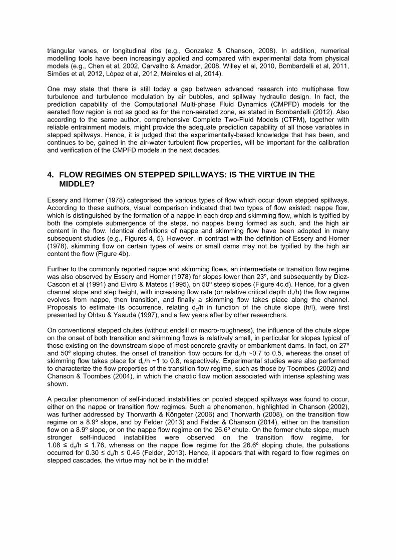
Essery and Horner (1978) categorised the various types of flow which occur down stepped spillways. According to these authors, visual comparison indicated that two types of flow existed: nappe flow, which is distinguished by the formation of a nappe in each drop and skimming flow, which is typified by both the complete submergence of the steps, no nappes being formed as such, and the high air content in the flow. Identical definitions of nappe and skimming flow have been adopted in many subsequent studies (e.g., Figures 4, 5). However, in contrast with the definition of Essery and Horner (1978), skimming flow on certain types of weirs or small dams may not be typified by the high air content the flow (Figure 4b). Further to the commonly reported nappe and skimming flows, an intermediate or transition flow regime was also observed by Essery and Horner (1978) for slopes lower than 23º, and subsequently by Diez-Cascon et al (1991) and Elviro & Mateos (1995), on 50º steep slopes (Figure 4c,d). Hence, for a given channel slope and step height, with increasing flow rate (or relative critical depth dc/h) the flow regime evolves from nappe, then transition, and finally a skimming flow takes place along the channel. Proposals to estimate its occurrence, relating dc/h in function of the chute slope (h/l), were first presented by Ohtsu & Yasuda (1997), and a few years after by other researchers. On conventional stepped chutes (without endsill or macro-roughness), the influence of the chute slope on the onset of both transition and skimming flows is relatively small, in particular for slopes typical of those existing on the downstream slope of most concrete gravity or embankment dams. In fact, on 27º and 50º sloping chutes, the onset of transition flow occurs for dc/h ~0.7 to 0.5, whereas the onset of skimming flow takes place for dc/h ~1 to 0.8, respectively. Experimental studies were also performed to characterize the flow properties of the transition flow regime, such as those by Toombes (2002) and Chanson & Toombes (2004), in which the chaotic flow motion associated with intense splashing was shown. A peculiar phenomenon of self-induced instabilities on pooled stepped spillways was found to occur, either on the nappe or transition flow regimes. Such a phenomenon, highlighted in Chanson (2002), was further addressed by Thorwarth & Köngeter (2006) and Thorwarth (2008), on the transition flow regime on a 8.9º slope, and by Felder (2013) and Felder & Chanson (2014), either on the transition flow on a 8.9º slope, or on the nappe flow regime on the 26.6º chute. On the former chute slope, much stronger self-induced instabilities were observed on the transition flow regime, for 1.08 ≤ dc/h ≤ 1.76, whereas on the nappe flow regime for the 26.6º sloping chute, the pulsations occurred for 0.30 ≤ dc/h ≤ 0.45 (Felder, 2013). Hence, it appears that with regard to flow regimes on stepped cascades, the virtue may not be in the middle!
(a) (b)
(c) (d)
Figure 4 – Flow regimes on sloping chutes assembled at IST (27º slope), and LNEC (53º slope): (a) nappe flow (dc/h = 0.50); (b) skimming flow (dc/h = 1.26); (c) and (d) transition flow (dc/h = 0.69)
(a) (b)
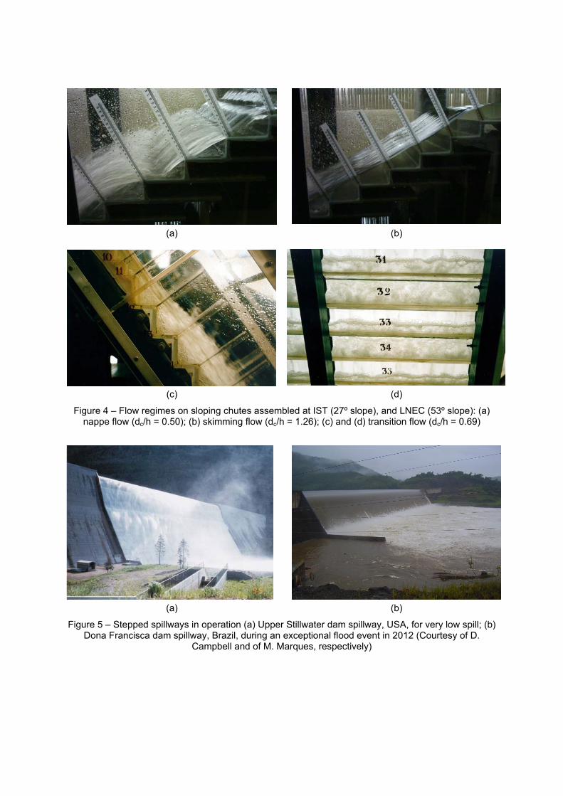
Figure 5 – Stepped spillways in operation (a) Upper Stillwater dam spillway, USA, for very low spill; (b) Dona Francisca dam spillway, Brazil, during an exceptional flood event in 2012 (Courtesy of D.
Campbell and of M. Marques, respectively)
5. SKIMMING FLOW ON STEEP SLOPES: LABYRINTHS OF RESEARCH
5.1. Skimming and self-aerated chute flows: what are the differences?
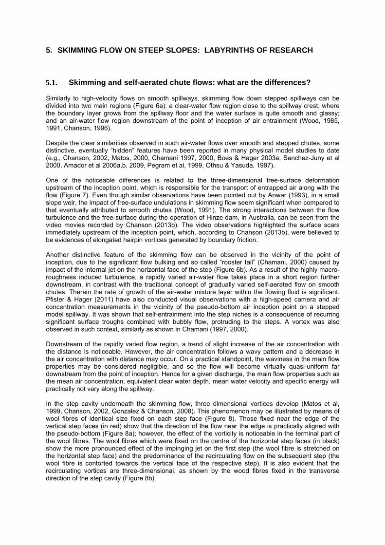
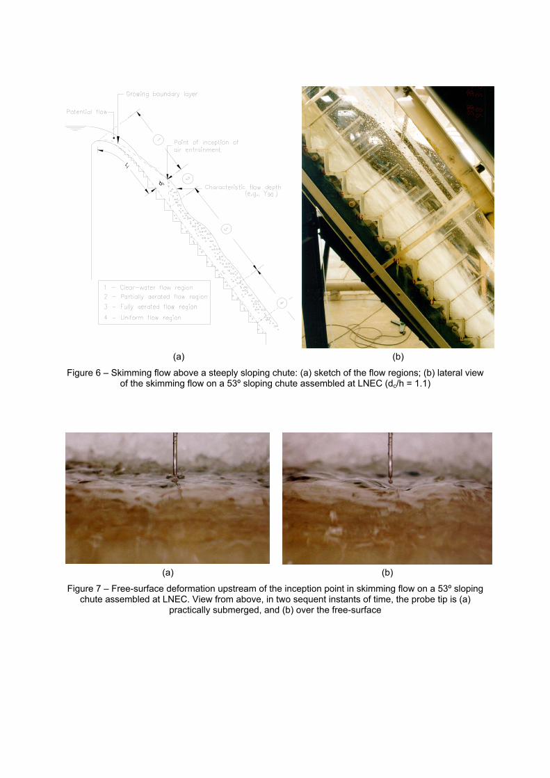
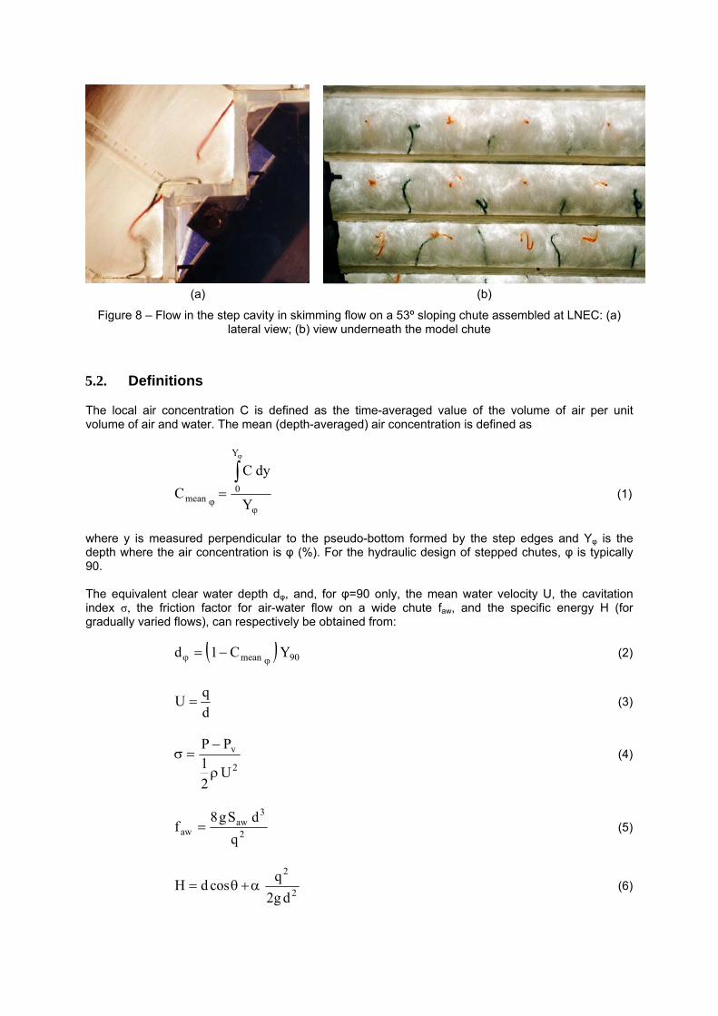
Similarly to high-velocity flows on smooth spillways, skimming flow down stepped spillways can be divided into two main regions (Figure 6a): a clear-water flow region close to the spillway crest, where the boundary layer grows from the spillway floor and the water surface is quite smooth and glassy; and an air-water flow region downstream of the point of inception of air entrainment (Wood, 1985, 1991, Chanson, 1996). Despite the clear similarities observed in such air-water flows over smooth and stepped chutes, some distinctive, eventually “hidden” features have been reported in many physical model studies to date (e.g., Chanson, 2002, Matos, 2000, Chamani 1997, 2000, Boes & Hager 2003a, Sanchez-Juny et al 2000, Amador et al 2006a,b, 2009, Pegram et al, 1999, Othsu & Yasuda, 1997). One of the noticeable differences is related to the three-dimensional free-surface deformation upstream of the inception point, which is responsible for the transport of entrapped air along with the flow (Figure 7). Even though similar observations have been pointed out by Anwar (1993), in a small slope weir, the impact of free-surface undulations in skimming flow seem significant when compared to that eventually attributed to smooth chutes (Wood, 1991). The strong interactions between the flow turbulence and the free-surface during the operation of Hinze dam, in Australia, can be seen from the video movies recorded by Chanson (2013b). The video observations highlighted the surface scars immediately upstream of the inception point, which, according to Chanson (2013b), were believed to be evidences of elongated hairpin vortices generated by boundary friction. Another distinctive feature of the skimming flow can be observed in the vicinity of the point of inception, due to the significant flow bulking and so called “rooster tail” (Chamani, 2000) caused by impact of the internal jet on the horizontal face of the step (Figure 6b). As a result of the highly macro-roughness induced turbulence, a rapidly varied air-water flow takes place in a short region further downstream, in contrast with the traditional concept of gradually varied self-aerated flow on smooth chutes. Therein the rate of growth of the air-water mixture layer within the flowing fluid is significant. Pfister & Hager (2011) have also conducted visual observations with a high-speed camera and air concentration measurements in the vicinity of the pseudo-bottom air inception point on a stepped model spillway. It was shown that self-entrainment into the step niches is a consequence of recurring significant surface troughs combined with bubbly flow, protruding to the steps. A vortex was also observed in such context, similarly as shown in Chamani (1997, 2000). Downstream of the rapidly varied flow region, a trend of slight increase of the air concentration with the distance is noticeable. However, the air concentration follows a wavy pattern and a decrease in the air concentration with distance may occur. On a practical standpoint, the waviness in the main flow properties may be considered negligible, and so the flow will become virtually quasi-uniform far downstream from the point of inception. Hence for a given discharge, the main flow properties such as the mean air concentration, equivalent clear water depth, mean water velocity and specific energy will practically not vary along the spillway. In the step cavity underneath the skimming flow, three dimensional vortices develop (Matos et al, 1999, Chanson, 2002, Gonzalez & Chanson, 2008). This phenomenon may be illustrated by means of wool fibres of identical size fixed on each step face (Figure 8). Those fixed near the edge of the vertical step faces (in red) show that the direction of the flow near the edge is practically aligned with the pseudo-bottom (Figure 8a); however, the effect of the vorticity is noticeable in the terminal part of the wool fibres. The wool fibres which were fixed on the centre of the horizontal step faces (in black) show the more pronounced effect of the impinging jet on the first step (the wool fibre is stretched on the horizontal step face) and the predominance of the recirculating flow on the subsequent step (the wool fibre is contorted towards the vertical face of the respective step). It is also evident that the recirculating vortices are three-dimensional, as shown by the wood fibres fixed in the transverse direction of the step cavity (Figure 8b).
(a) (b)
Figure 6 – Skimming flow above a steeply sloping chute: (a) sketch of the flow regions; (b) lateral view of the skimming flow on a 53º sloping chute assembled at LNEC (dc/h = 1.1)
(a) (b)
Figure 7 – Free-surface deformation upstream of the inception point in skimming flow on a 53º sloping chute assembled at LNEC. View from above, in two sequent instants of time, the probe tip is (a)
practically submerged, and (b) over the free-surface
(a) (b)
Figure 8 – Flow in the step cavity in skimming flow on a 53º sloping chute assembled at LNEC: (a) lateral view; (b) view underneath the model chute
5.2. Definitions
The local air concentration C is defined as the time-averaged value of the volume of air per unit volume of air and water. The mean (depth-averaged) air concentration is defined as
Y
dyC
C
Y
0mean (1)
where y is measured perpendicular to the pseudo-bottom formed by the step edges and Yφ is the depth where the air concentration is φ (%). For the hydraulic design of stepped chutes, φ is typically 90. The equivalent clear water depth dφ, and, for φ=90 only, the mean water velocity U, the cavitation index σ, the friction factor for air-water flow on a wide chute faw, and the specific energy H (for gradually varied flows), can respectively be obtained from: 90mean YC1d
(2)
d
qU (3)
2
v
U2
1PP
(4)
2
3aw
awq
dSg8f (5)
2
2
dg2
qcosdH (6)
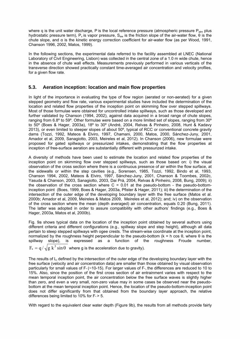
where q is the unit water discharge, P is the local reference pressure (atmospheric pressure Patm plus hydrostatic pressure term), Pv is vapor pressure, Saw is the friction slope of the air-water flow, θ is the chute slope, and α is the kinetic energy correction coefficient for air-water flow (as per Wood, 1991, Chanson 1996, 2002, Matos, 1999). In the following sections, the experimental data referred to the facility assembled at LNEC (National Laboratory of Civil Engineering, Lisbon) was collected in the central zone of a 1.0 m wide chute, hence in the absence of chute wall effects. Measurements previously performed in various verticals of the transverse direction showed practically constant time-averaged air concentration and velocity profiles, for a given flow rate.
5.3. Aeration inception: location and main flow properties
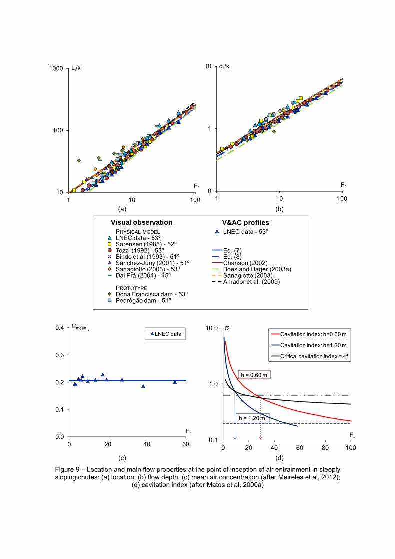
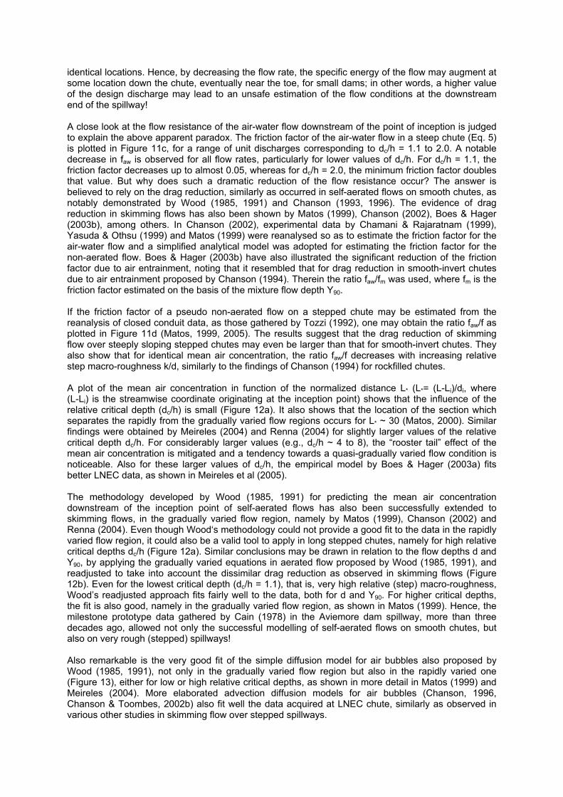
In light of the importance in evaluating the type of flow region (aerated or non-aerated) for a given stepped geometry and flow rate, various experimental studies have included the determination of the location and related flow properties of the inception point on skimming flow over stepped spillways. Most of those formulae were obtained for uncontrolled intake spillways, such as those developed and further validated by Chanson (1994, 2002), against data acquired in a broad range of chute slopes, ranging from 6.8º to 59º. Other formulae were based on a more limited set of slopes, ranging from 30º to 50º (Boes & Hager, 2003a), 18º to 30º (André, 2004, Relvas & Pinheiro, 2008, Hunt & Kadavy 2013), or even limited to steeper slopes of about 50º, typical of RCC or conventional concrete gravity dams (Tozzi, 1992, Mateos & Elviro, 1997, Chamani, 2000, Matos, 2000, Sánchez-Juny, 2001, Amador et al, 2009, Sanagiotto, 2003, Meireles et al, 2012). In Chanson (2006), new formulae were proposed for gated spillways or pressurized intakes, demonstrating that the flow properties at inception of free-surface aeration are substantially different with pressurized intake. A diversity of methods have been used to estimate the location and related flow properties of the inception point on skimming flow over stepped spillways, such as those based on: i) the visual observation of the cross section where there is a continuous presence of air within the flow surface, at the sidewalls or within the step cavities (e.g., Sorensen, 1985, Tozzi, 1992, Bindo et al, 1993, Chanson 1994, 2002, Mateos & Elviro, 1997, Sánchez-Juny, 2001, Chanson & Toombes, 2002c, Yasuda & Chanson, 2003, Sanagiotto, 2003, Dai Prá, 2004, Relvas & Pinheiro, 2008, Bung, 2009); ii) the observation of the cross section where C = 0.01 at the pseudo-bottom - the pseudo-bottom-inception point (Boes, 1999, Boes & Hager, 2003a, Pfister & Hager, 2011); iii) the determination of the intersection of the outer edge of the developing boundary layer with the free surface (Matos et al. 2000b; Amador et al, 2009, Meireles & Matos 2009, Meireles et al, 2012); and; iv) on the observation of the cross section where the mean (depth averaged) air concentration, equals 0.20 (Bung, 2011). The latter was adopted in order to assure compatibility with other authors’ findings (e.g., Boes & Hager, 2003a, Matos et al, 2000b). Fig. 9a shows typical data on the location of the inception point obtained by several authors using different criteria and different configurations (e.g., spillway slope and step height), although all data pertain to steep stepped spillways with ogee crests. The stream-wise coordinate at the inception point, normalized by the roughness height perpendicular to the pseudo-bottom (k = h cos θ, where θ is the spillway slope), is expressed as a function of the roughness Froude number,
sinkg/qF 3* where g is the acceleration due to gravity).
The results of Li defined by the intersection of the outer edge of the developing boundary layer with the free surface (velocity and air concentration data) are smaller than those obtained by visual observation particularly for small values of F* (~10-15). For larger values of F*, the differences are reduced to 10 to 15%. Also, since the position of the first cross section of air entrainment varies with respect to the mean temporal inception point, the air concentration below the free surface waves is slightly higher than zero, and even a very small, non-zero value may in some cases be observed near the pseudo-bottom at the mean temporal inception point. Hence, the location of the pseudo-bottom-inception point does not differ significantly from that obtained from the boundary layer approach, the relative differences being limited to 10% for F* > 5. With regard to the equivalent clear water depth (Figure 9b), the results from all methods provide fairly
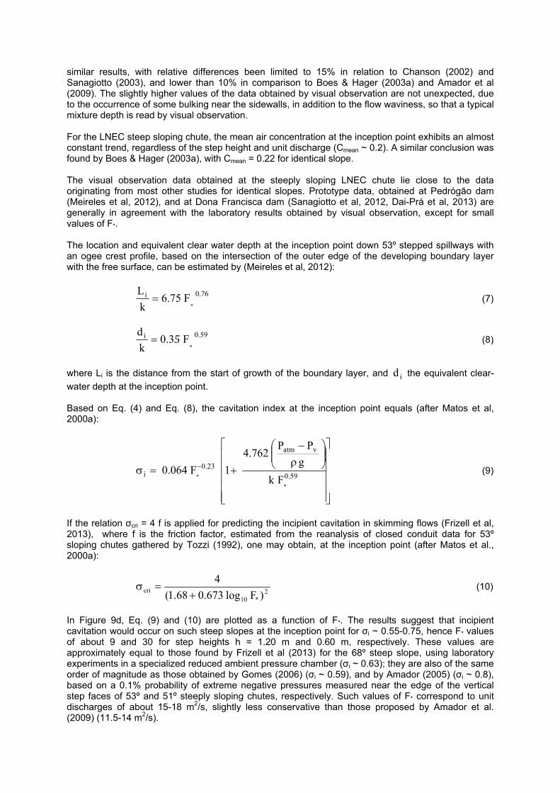
similar results, with relative differences been limited to 15% in relation to Chanson (2002) and Sanagiotto (2003), and lower than 10% in comparison to Boes & Hager (2003a) and Amador et al (2009). The slightly higher values of the data obtained by visual observation are not unexpected, due to the occurrence of some bulking near the sidewalls, in addition to the flow waviness, so that a typical mixture depth is read by visual observation. For the LNEC steep sloping chute, the mean air concentration at the inception point exhibits an almost constant trend, regardless of the step height and unit discharge (Cmean ~ 0.2). A similar conclusion was found by Boes & Hager (2003a), with Cmean = 0.22 for identical slope. The visual observation data obtained at the steeply sloping LNEC chute lie close to the data originating from most other studies for identical slopes. Prototype data, obtained at Pedrógão dam (Meireles et al, 2012), and at Dona Francisca dam (Sanagiotto et al, 2012, Dai-Prá et al, 2013) are generally in agreement with the laboratory results obtained by visual observation, except for small values of F*. The location and equivalent clear water depth at the inception point down 53º stepped spillways with an ogee crest profile, based on the intersection of the outer edge of the developing boundary layer with the free surface, can be estimated by (Meireles et al, 2012):
76.0i
*F75.6
k
L (7)
59.0i
*F3.0
k
d5 (8)
where Li is the distance from the start of growth of the boundary layer, and id the equivalent clear-
water depth at the inception point. Based on Eq. (4) and Eq. (8), the cavitation index at the inception point equals (after Matos et al, 2000a):
59.0
vatm
23.0i
*
* Fk
g
PP762.4
1F064.0 (9)
If the relation σcri = 4 f is applied for predicting the incipient cavitation in skimming flows (Frizell et al, 2013), where f is the friction factor, estimated from the reanalysis of closed conduit data for 53º sloping chutes gathered by Tozzi (1992), one may obtain, at the inception point (after Matos et al., 2000a):
2*10
cri )Flog673.068.1(
4
(10)
In Figure 9d, Eq. (9) and (10) are plotted as a function of F*. The results suggest that incipient cavitation would occur on such steep slopes at the inception point for σi ~ 0.55-0.75, hence F* values of about 9 and 30 for step heights h = 1.20 m and 0.60 m, respectively. These values are approximately equal to those found by Frizell et al (2013) for the 68º steep slope, using laboratory experiments in a specialized reduced ambient pressure chamber (σi ~ 0.63); they are also of the same order of magnitude as those obtained by Gomes (2006) (σi ~ 0.59), and by Amador (2005) (σi ~ 0.8), based on a 0.1% probability of extreme negative pressures measured near the edge of the vertical step faces of 53º and 51º steeply sloping chutes, respectively. Such values of F* correspond to unit discharges of about 15-18 m2/s, slightly less conservative than those proposed by Amador et al. (2009) (11.5-14 m2/s).
10
100
1000
1 10 100
Li/k
F*0
1
10
1 10 100
di /k
F*
(a) (b)
PHYSICAL MODEL LNEC data - 53ºLNEC data - 53ºSorensen (1985) - 52ºTozzi (1992) - 53º Eq. (7)Bindo et al (1993) - 51º Eq. (8)Sánchez-Juny (2001) - 51º Chanson (2002)Sanagiotto (2003) - 53º Boes and Hager (2003a)Dai Prá (2004) - 45º Sanagiotto (2003)
Amador et al. (2009)PROTOTYPEDona Francisca dam - 53ºPedrógão dam - 51º
V&AC profilesVisual observation
0.0
0.1
0.2
0.3
0.4
0 20 40 60
Cmean
F*
LNEC datai
0.1
1.0
10.0
0 20 40 60 80 100
Cavitation index: h=0.60 m
Cavitation index: h=1.20 m
Critical cavitation index = 4f
F*
i
h = 0.60 m
h = 1.20 m
(c) (d)
Figure 9 – Location and main flow properties at the point of inception of air entrainment in steeply sloping chutes: (a) location; (b) flow depth; (c) mean air concentration (after Meireles et al, 2012);
(d) cavitation index (after Matos et al, 2000a)
5.4. The clear-water flow region
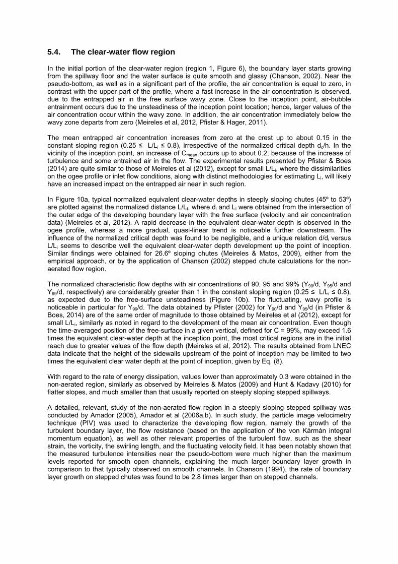
In the initial portion of the clear-water region (region 1, Figure 6), the boundary layer starts growing from the spillway floor and the water surface is quite smooth and glassy (Chanson, 2002). Near the pseudo-bottom, as well as in a significant part of the profile, the air concentration is equal to zero, in contrast with the upper part of the profile, where a fast increase in the air concentration is observed, due to the entrapped air in the free surface wavy zone. Close to the inception point, air-bubble entrainment occurs due to the unsteadiness of the inception point location; hence, larger values of the air concentration occur within the wavy zone. In addition, the air concentration immediately below the wavy zone departs from zero (Meireles et al, 2012, Pfister & Hager, 2011). The mean entrapped air concentration increases from zero at the crest up to about 0.15 in the constant sloping region (0.25 ≤ L/Li ≤ 0.8), irrespective of the normalized critical depth dc/h. In the vicinity of the inception point, an increase of Cmean occurs up to about 0.2, because of the increase of turbulence and some entrained air in the flow. The experimental results presented by Pfister & Boes (2014) are quite similar to those of Meireles et al (2012), except for small L/Li, where the dissimilarities on the ogee profile or inlet flow conditions, along with distinct methodologies for estimating Li, will likely have an increased impact on the entrapped air near in such region. In Figure 10a, typical normalized equivalent clear-water depths in steeply sloping chutes (45º to 53º) are plotted against the normalized distance L/Li, where di and Li were obtained from the intersection of the outer edge of the developing boundary layer with the free surface (velocity and air concentration data) (Meireles et al, 2012). A rapid decrease in the equivalent clear-water depth is observed in the ogee profile, whereas a more gradual, quasi-linear trend is noticeable further downstream. The influence of the normalized critical depth was found to be negligible, and a unique relation d/di versus L/Li seems to describe well the equivalent clear-water depth development up the point of inception. Similar findings were obtained for 26.6º sloping chutes (Meireles & Matos, 2009), either from the empirical approach, or by the application of Chanson (2002) stepped chute calculations for the non-aerated flow region. The normalized characteristic flow depths with air concentrations of 90, 95 and 99% (Y90/d, Y95/d and Y99/d, respectively) are considerably greater than 1 in the constant sloping region (0.25 ≤ L/Li ≤ 0.8), as expected due to the free-surface unsteadiness (Figure 10b). The fluctuating, wavy profile is noticeable in particular for Y99/d. The data obtained by Pfister (2002) for Y90/d and Y95/d (in Pfister & Boes, 2014) are of the same order of magnitude to those obtained by Meireles et al (2012), except for small L/Li, similarly as noted in regard to the development of the mean air concentration. Even though the time-averaged position of the free-surface in a given vertical, defined for C = 99%, may exceed 1.6 times the equivalent clear-water depth at the inception point, the most critical regions are in the initial reach due to greater values of the flow depth (Meireles et al, 2012). The results obtained from LNEC data indicate that the height of the sidewalls upstream of the point of inception may be limited to two times the equivalent clear water depth at the point of inception, given by Eq. (8). With regard to the rate of energy dissipation, values lower than approximately 0.3 were obtained in the non-aerated region, similarly as observed by Meireles & Matos (2009) and Hunt & Kadavy (2010) for flatter slopes, and much smaller than that usually reported on steeply sloping stepped spillways. A detailed, relevant, study of the non-aerated flow region in a steeply sloping stepped spillway was conducted by Amador (2005), Amador et al (2006a,b). In such study, the particle image velocimetry technique (PIV) was used to characterize the developing flow region, namely the growth of the turbulent boundary layer, the flow resistance (based on the application of the von Kármán integral momentum equation), as well as other relevant properties of the turbulent flow, such as the shear strain, the vorticity, the swirling length, and the fluctuating velocity field. It has been notably shown that the measured turbulence intensities near the pseudo-bottom were much higher than the maximum levels reported for smooth open channels, explaining the much larger boundary layer growth in comparison to that typically observed on smooth channels. In Chanson (1994), the rate of boundary layer growth on stepped chutes was found to be 2.8 times larger than on stepped channels.
0.5
1.0
1.5
2.0
2.5
0.0 0.2 0.4 0.6 0.8 1.0
d/di
L/Li
LNEC data - 53ºTozzi (1992) - 53ºSanagiotto (2003) - 53ºDai Prá (2004) - 45ºAmador et al (2009) - 51ºMeireles et al (2012) - 53º
1.0
1.2
1.4
1.6
1.8
0.2 0.4 0.6 0.8 1.0
L/Li
LNEC data
Y /d
Y /d
Y /d
Pfister (2002)
Y /d
Y /d
Y /d
90
95
90
95
99
(a) (b)
Figure 10 – Main flow properties in the non-aerated flow region of steeply sloping chutes: (a) normalized equivalent clear-water depth; (b) characteristic flow depths (after Meireles et at, 2012,
data by Pfister (2002) obtained through digitization)
5.5. The self-aerated flow region
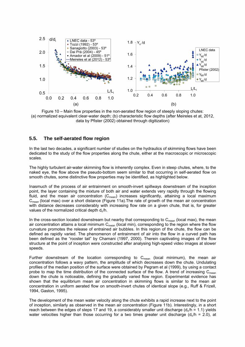
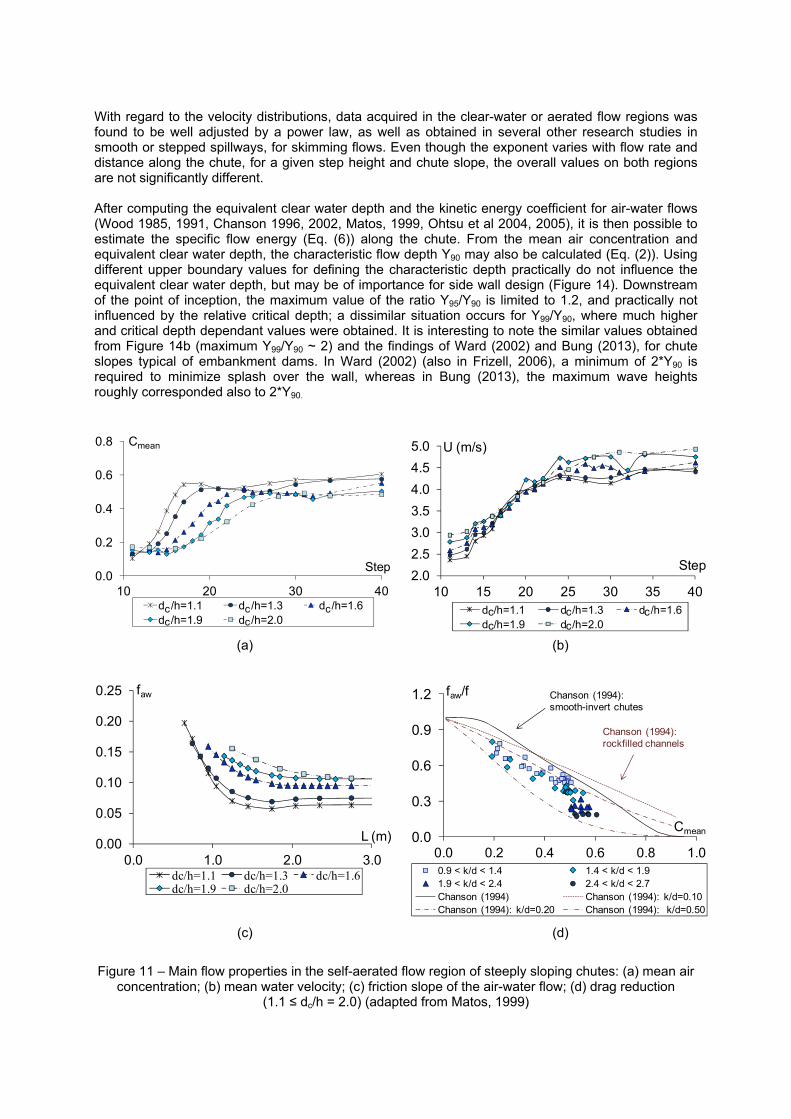
In the last two decades, a significant number of studies on the hydraulics of skimming flows have been dedicated to the study of the flow properties along the chute, either at the macroscopic or microscopic scales. The highly turbulent air-water skimming flow is inherently complex. Even in steep chutes, where, to the naked eye, the flow above the pseudo-bottom seem similar to that occurring in self-aerated flow on smooth chutes, some distinctive flow properties may be identified, as highlighted below. Inasmuch of the process of air entrainment on smooth-invert spillways downstream of the inception point, the layer containing the mixture of both air and water extends very rapidly through the flowing fluid, and the mean air concentration (Cmean) increases significantly, attaining a local maximum Cmean (local max) over a short distance (Figure 11a).The rate of growth of the mean air concentration with distance decreases considerably with increasing flow rate on a given chute, that is, for greater values of the normalized critical depth dc/h. In the cross-section located downstream but nearby that corresponding to Cmean (local max), the mean air concentration attains a local minimum Cmean (local min), corresponding to the region where the flow curvature promotes the release of entrained air bubbles. In this region of the chute, the flow can be defined as rapidly varied. The phenomenon of entrainment of air into the flow in a curved path has been defined as the “rooster tail” by Chamani (1997, 2000). Therein captivating images of the flow structure at the point of inception were constructed after analysing high-speed video images at slower speeds. Further downstream of the location corresponding to Cmean (local minimum), the mean air concentration follows a wavy pattern, the amplitude of which decreases down the chute. Undulating profiles of the median position of the surface were obtained by Pegram et al (1999), by using a contact probe to map the time distribution of the connected surface of the flow. A trend of increasing Cmean down the chute is noticeable, defining the gradually varied flow region. Experimental evidence has shown that the equilibrium mean air concentration in skimming flows is similar to the mean air concentration in uniform aerated flow on smooth-invert chutes of identical slope (e.g., Ruff & Frizell, 1994, Gaston, 1995). The development of the mean water velocity along the chute exhibits a rapid increase next to the point of inception, similarly as observed in the mean air concentration (Figure 11b). Interestingly, in a short reach between the edges of steps 17 and 19, a considerably smaller unit discharge (dc/h = 1.1) yields water velocities higher than those occurring for a two times greater unit discharge (dc/h = 2.0), at
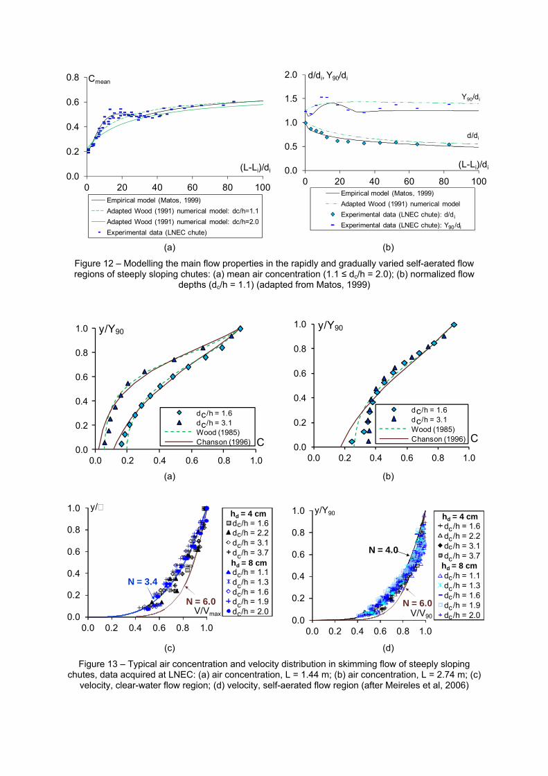
identical locations. Hence, by decreasing the flow rate, the specific energy of the flow may augment at some location down the chute, eventually near the toe, for small dams; in other words, a higher value of the design discharge may lead to an unsafe estimation of the flow conditions at the downstream end of the spillway! A close look at the flow resistance of the air-water flow downstream of the point of inception is judged to explain the above apparent paradox. The friction factor of the air-water flow in a steep chute (Eq. 5) is plotted in Figure 11c, for a range of unit discharges corresponding to dc/h = 1.1 to 2.0. A notable decrease in faw is observed for all flow rates, particularly for lower values of dc/h. For dc/h = 1.1, the friction factor decreases up to almost 0.05, whereas for dc/h = 2.0, the minimum friction factor doubles that value. But why does such a dramatic reduction of the flow resistance occur? The answer is believed to rely on the drag reduction, similarly as occurred in self-aerated flows on smooth chutes, as notably demonstrated by Wood (1985, 1991) and Chanson (1993, 1996). The evidence of drag reduction in skimming flows has also been shown by Matos (1999), Chanson (2002), Boes & Hager (2003b), among others. In Chanson (2002), experimental data by Chamani & Rajaratnam (1999), Yasuda & Othsu (1999) and Matos (1999) were reanalysed so as to estimate the friction factor for the air-water flow and a simplified analytical model was adopted for estimating the friction factor for the non-aerated flow. Boes & Hager (2003b) have also illustrated the significant reduction of the friction factor due to air entrainment, noting that it resembled that for drag reduction in smooth-invert chutes due to air entrainment proposed by Chanson (1994). Therein the ratio faw/fm was used, where fm is the friction factor estimated on the basis of the mixture flow depth Y90. If the friction factor of a pseudo non-aerated flow on a stepped chute may be estimated from the reanalysis of closed conduit data, as those gathered by Tozzi (1992), one may obtain the ratio faw/f as plotted in Figure 11d (Matos, 1999, 2005). The results suggest that the drag reduction of skimming flow over steeply sloping stepped chutes may even be larger than that for smooth-invert chutes. They also show that for identical mean air concentration, the ratio faw/f decreases with increasing relative step macro-roughness k/d, similarly to the findings of Chanson (1994) for rockfilled chutes. A plot of the mean air concentration in function of the normalized distance L* (L*= (L-Li)/di, where (L-Li) is the streamwise coordinate originating at the inception point) shows that the influence of the relative critical depth (dc/h) is small (Figure 12a). It also shows that the location of the section which separates the rapidly from the gradually varied flow regions occurs for L* ~ 30 (Matos, 2000). Similar findings were obtained by Meireles (2004) and Renna (2004) for slightly larger values of the relative critical depth dc/h. For considerably larger values (e.g., dc/h ~ 4 to 8), the “rooster tail” effect of the mean air concentration is mitigated and a tendency towards a quasi-gradually varied flow condition is noticeable. Also for these larger values of dc/h, the empirical model by Boes & Hager (2003a) fits better LNEC data, as shown in Meireles et al (2005). The methodology developed by Wood (1985, 1991) for predicting the mean air concentration downstream of the inception point of self-aerated flows has also been successfully extended to skimming flows, in the gradually varied flow region, namely by Matos (1999), Chanson (2002) and Renna (2004). Even though Wood‘s methodology could not provide a good fit to the data in the rapidly varied flow region, it could also be a valid tool to apply in long stepped chutes, namely for high relative critical depths dc/h (Figure 12a). Similar conclusions may be drawn in relation to the flow depths d and Y90, by applying the gradually varied equations in aerated flow proposed by Wood (1985, 1991), and readjusted to take into account the dissimilar drag reduction as observed in skimming flows (Figure 12b). Even for the lowest critical depth (dc/h = 1.1), that is, very high relative (step) macro-roughness, Wood’s readjusted approach fits fairly well to the data, both for d and Y90. For higher critical depths, the fit is also good, namely in the gradually varied flow region, as shown in Matos (1999). Hence, the milestone prototype data gathered by Cain (1978) in the Aviemore dam spillway, more than three decades ago, allowed not only the successful modelling of self-aerated flows on smooth chutes, but also on very rough (stepped) spillways! Also remarkable is the very good fit of the simple diffusion model for air bubbles also proposed by Wood (1985, 1991), not only in the gradually varied flow region but also in the rapidly varied one (Figure 13), either for low or high relative critical depths, as shown in more detail in Matos (1999) and Meireles (2004). More elaborated advection diffusion models for air bubbles (Chanson, 1996, Chanson & Toombes, 2002b) also fit well the data acquired at LNEC chute, similarly as observed in various other studies in skimming flow over stepped spillways.
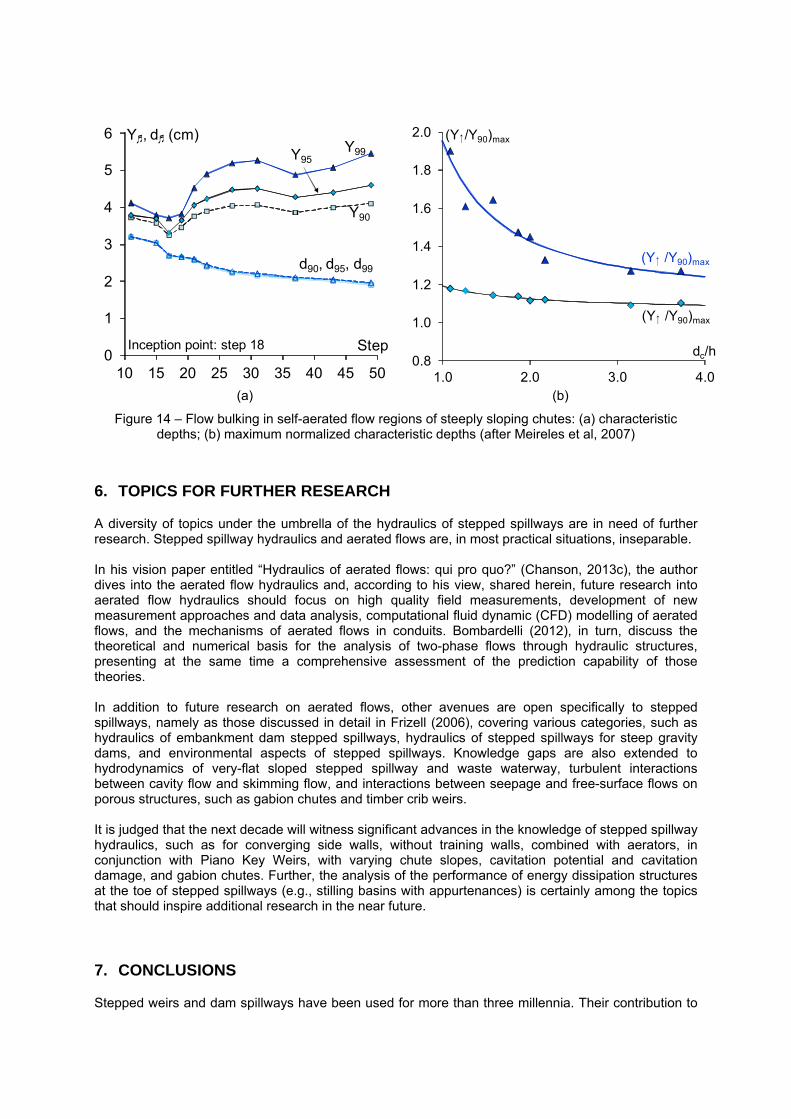
With regard to the velocity distributions, data acquired in the clear-water or aerated flow regions was found to be well adjusted by a power law, as well as obtained in several other research studies in smooth or stepped spillways, for skimming flows. Even though the exponent varies with flow rate and distance along the chute, for a given step height and chute slope, the overall values on both regions are not significantly different. After computing the equivalent clear water depth and the kinetic energy coefficient for air-water flows (Wood 1985, 1991, Chanson 1996, 2002, Matos, 1999, Ohtsu et al 2004, 2005), it is then possible to estimate the specific flow energy (Eq. (6)) along the chute. From the mean air concentration and equivalent clear water depth, the characteristic flow depth Y90 may also be calculated (Eq. (2)). Using different upper boundary values for defining the characteristic depth practically do not influence the equivalent clear water depth, but may be of importance for side wall design (Figure 14). Downstream of the point of inception, the maximum value of the ratio Y95/Y90 is limited to 1.2, and practically not influenced by the relative critical depth; a dissimilar situation occurs for Y99/Y90, where much higher and critical depth dependant values were obtained. It is interesting to note the similar values obtained from Figure 14b (maximum Y99/Y90 ~ 2) and the findings of Ward (2002) and Bung (2013), for chute slopes typical of embankment dams. In Ward (2002) (also in Frizell, 2006), a minimum of 2*Y90 is required to minimize splash over the wall, whereas in Bung (2013), the maximum wave heights roughly corresponded also to 2*Y90.
0.0
0.2
0.4
0.6
0.8
10 20 30 40
Step
d /h=1.1 d /h=1.3 d /h=1.6d /h=1.9 d /h=2.0
Cmean
c c cc c
2.0
2.5
3.0
3.5
4.0
4.5
5.0
10 15 20 25 30 35 40
Step
d /h=1.1 d /h=1.3 d /h=1.6d /h=1.9 d /h=2.0
U (m/s)
c c cc c
(a) (b)
0.00
0.05
0.10
0.15
0.20
0.25
0.0 1.0 2.0 3.0
L (m)
dc/h=1.1 dc/h=1.3 dc/h=1.6dc/h=1.9 dc/h=2.0
faw
0.0
0.3
0.6
0.9
1.2
0.0 0.2 0.4 0.6 0.8 1.0
Cmean
0.9 < k/d < 1.4 1.4 < k/d < 1.91.9 < k/d < 2.4 2.4 < k/d < 2.7Chanson (1994) Chanson (1994): k/d=0.10Chanson (1994): k/d=0.20 Chanson (1994): k/d=0.50
faw/f Chanson (1994): smooth-invert chutes
Chanson (1994): rockfilled channels
(c) (d)
Figure 11 – Main flow properties in the self-aerated flow region of steeply sloping chutes: (a) mean air concentration; (b) mean water velocity; (c) friction slope of the air-water flow; (d) drag reduction
(1.1 ≤ dc/h = 2.0) (adapted from Matos, 1999)
0.0
0.2
0.4
0.6
0.8
0 20 40 60 80 100
(L-Li)/di
Empirical model (Matos, 1999)
Adapted Wood (1991) numerical model: dc/h=1.1
Adapted Wood (1991) numerical model: dc/h=2.0
Experimental data (LNEC chute)
Cmean
0.0
0.5
1.0
1.5
2.0
0 20 40 60 80 100
(L-Li)/di
Empirical model (Matos, 1999)
Adapted Wood (1991) numerical model
Experimental data (LNEC chute): d/d
Experimental data (LNEC chute): Y /d
d/di, Y90/di
Y90/di
d/di
i
90 i
(a) (b)
Figure 12 – Modelling the main flow properties in the rapidly and gradually varied self-aerated flow regions of steeply sloping chutes: (a) mean air concentration (1.1 ≤ dc/h = 2.0); (b) normalized flow
depths (dc/h = 1.1) (adapted from Matos, 1999)
0.0
0.2
0.4
0.6
0.8
1.0
0.0 0.2 0.4 0.6 0.8 1.0
y/Y90
C
d /h = 1.6d /h = 3.1Wood (1985)Chanson (1996)
cc
0.0
0.2
0.4
0.6
0.8
1.0
0.0 0.2 0.4 0.6 0.8 1.0
y/Y90
C
d /h = 1.6d /h = 3.1Wood (1985)Chanson (1996)
cc
(a) (b)
0.0
0.2
0.4
0.6
0.8
1.0
0.0 0.2 0.4 0.6 0.8 1.0
y/
V/Vmax
d /h = 1.6d /h = 2.2d /h = 3.1d /h = 3.7
d /h = 1.1d /h = 1.3d /h = 1.6d /h = 1.9d /h = 2.0
hd = 4 cm
hd = 8 cm
N = 3.4
N = 6.0
cc
c
c
c
cc
cc
0.0
0.2
0.4
0.6
0.8
1.0
0.0 0.2 0.4 0.6 0.8 1.0
y/Y90
V/V90
N = 4.0
d /h = 1.6d /h = 2.2d /h = 3.1d /h = 3.7
d /h = 1.1d /h = 1.3d /h = 1.6d /h = 1.9d /h = 2.0
hd = 4 cm
hd = 8 cm
N = 6.0
ccc
c
c
cc
cc
(c) (d)
Figure 13 – Typical air concentration and velocity distribution in skimming flow of steeply sloping chutes, data acquired at LNEC: (a) air concentration, L = 1.44 m; (b) air concentration, L = 2.74 m; (c)
velocity, clear-water flow region; (d) velocity, self-aerated flow region (after Meireles et al, 2006)
0
1
2
3
4
5
6
10 15 20 25 30 35 40 45 50
Step
Y�, d� (cm)
Y90
Y95Y99
d90, d95, d99
Inception point: step 18
0.8
1.0
1.2
1.4
1.6
1.8
2.0
1.0 2.0 3.0 4.0
(Y�/Y90)max
dc/h
(Y� /Y90)max
(Y� /Y90)max
(a) (b)
Figure 14 – Flow bulking in self-aerated flow regions of steeply sloping chutes: (a) characteristic depths; (b) maximum normalized characteristic depths (after Meireles et al, 2007)
6. TOPICS FOR FURTHER RESEARCH
A diversity of topics under the umbrella of the hydraulics of stepped spillways are in need of further research. Stepped spillway hydraulics and aerated flows are, in most practical situations, inseparable. In his vision paper entitled “Hydraulics of aerated flows: qui pro quo?” (Chanson, 2013c), the author dives into the aerated flow hydraulics and, according to his view, shared herein, future research into aerated flow hydraulics should focus on high quality field measurements, development of new measurement approaches and data analysis, computational fluid dynamic (CFD) modelling of aerated flows, and the mechanisms of aerated flows in conduits. Bombardelli (2012), in turn, discuss the theoretical and numerical basis for the analysis of two-phase flows through hydraulic structures, presenting at the same time a comprehensive assessment of the prediction capability of those theories. In addition to future research on aerated flows, other avenues are open specifically to stepped spillways, namely as those discussed in detail in Frizell (2006), covering various categories, such as hydraulics of embankment dam stepped spillways, hydraulics of stepped spillways for steep gravity dams, and environmental aspects of stepped spillways. Knowledge gaps are also extended to hydrodynamics of very-flat sloped stepped spillway and waste waterway, turbulent interactions between cavity flow and skimming flow, and interactions between seepage and free-surface flows on porous structures, such as gabion chutes and timber crib weirs. It is judged that the next decade will witness significant advances in the knowledge of stepped spillway hydraulics, such as for converging side walls, without training walls, combined with aerators, in conjunction with Piano Key Weirs, with varying chute slopes, cavitation potential and cavitation damage, and gabion chutes. Further, the analysis of the performance of energy dissipation structures at the toe of stepped spillways (e.g., stilling basins with appurtenances) is certainly among the topics that should inspire additional research in the near future.
7. CONCLUSIONS
Stepped weirs and dam spillways have been used for more than three millennia. Their contribution to
the stability of the structure and to eventually dissipate flow energy may have been the natural drivers for such choices. However, the increased cost saving benefits associated with the Roller Compacted Concrete technique (RCC), either applied on gravity dams or on embankment dam overtopping, has prompted interest in stepped spillway hydraulic research. Even though most research into stepped spillway hydraulics until the mid 90’s was clearly on a more project oriented basis, implying that a comprehensive generalised knowledge was lacking by then, both applied and fundamental research have flourished side by side for the last two decades. Nowadays, “conventional” stepped spillways are applied in standard design practice. In fact, it is impressive to witness the development in this field of research, mostly on physical modelling, but more and more using numerical tools. While we may use today a variety of empirical models developed for predicting the main flow properties along the spillway, such as the depth-averaged mean air concentration, the bulked flow depths, the mean water velocity, the specific energy and the head loss, the air concentration and velocity distributions, some peculiar, intriguing aspects of the hydraulics of stepped spillways remain to enrich future discussions on the topic. Notably, some simple theoretical and numerical tools developed in the past for self-aerated flow on smooth chutes, may be considered adequate to predict some main skimming flow properties over stepped spillways. From the conventional stepped spillways, and frequently stimulated by practice needs, the research community rapidly initiated the study of other original solutions, such as stepped spillways with macro-roughness, converging stepped spillways, stepped spillways without guiding walls, aerators on stepped spillways, and stepped spillways combined with Piano Key Weirs, among other designs. However, and in a certain way paradoxically, a regression may have occurred in the sound design of energy dissipation structures, in particular if these are located downstream of stepped spillways over high dams. Hence, a fantastic window has opened for continuing the investigation on the topic of stepped spillways, and strengthen the links between practitioners and researchers worldwide. To conclude, let us reiterate what a leading practitioner wrote in a Keynote Lecture delivered at the 4th IAHR International Symposium on Hydraulic Structures (Campbell, 2012): “Remember, we are not attending the 4th IAHR International Symposium on Hydraulic Structures because we have chosen the easy path. Let us find common passions and, together, let us choose the right path”.
8. ACKNOWLEDGMENTS
The authors would like to thank Floriana Renna and Jaime Gomes, who conducted part of their Ph.D. theses at the IST in Lisbon, under the co-supervison of the first author, and in the framework of cooperation programs with the Politecnico di Bari, Italy, and the Universidade Federal do Rio Grande do Súl (UFRGS-IPH), Brazil, respectively. Unlike Inês Meireles, their professional paths after concluding the Ph.D. have not crossed, so far, in the academic career. We would also like to thank to Kathleen Frizell and Warren Frizell, formerly at Reclamation (USBR, USA), with whom the stimulating collaboration on stepped spillways was initiated and strengthened, since the mid 90’s. A word of thanks to Marcelo Marques, UFRGS-IPH and Fabián Bombardelli (University of California, Davis, USA), for their enriching past and on-going collaborations. An acknowledgement is also due to the National Laboratory of Civil Engineering (LNEC), Lisbon, in particular to Carlos Matias Ramos, former Head of the Hydraulic Structures Division, at the time when the experimental program was undertaken. On this occasion, a special word of recognition is due to António Quintela, engineer-professor-researcher, who served as a living example at the IST until his retirement, and with whom the first author had the privilege to work closely with; “Engineering = Art”, as Quintela would frequently say, is a perfect reflection of the way he used to see, to live, and kept on his profession. Last but not least, the distinguished invitation of the organizers to contribute to the symposium, namely Hubert Chanson and Robert Janssen, is warmly acknowledged.
9. REFERENCES
Ahmann, M. and Zapel, E. (2000). Stepped spillways, a dissolved gas abatement alternative, in Minor, H.E. and Hager, W.H. (Eds) Preprints of the Int. Workshop on Hydraulics of Stepped Spillways, Zürich, Switzerland, Balkema, 45-52. Amador, A. (2005). Comportamiento Hidráulico de los Aliviaderos Escalonados en Presas de
Hormigón Compactado, Ph.D. thesis, UPC, Barcelona, Spain (in Spanish). Amador, A., Sánchez-Juny, M. and Dolz, J. (2009). Developing flow region and pressure fluctuations on steeply sloping stepped spillways, J. Hydr. Eng., 135(12), 1092–1100. Amador, A., Sánchez-Juny, M., and Dolz, J. (2006a). DPIV Study of the Turbulent Boundary Layer over V-shaped Cavities, in Ferreira, R.M.L., Alves, E.C.T.L., Leal, J.G.A.B. and Cardoso, A.H. (Eds) Preprints of the Int. Conf. Fluvial Hydraulics River Flow 2006, Lisbon, Portugal, Topic A1, Balkema Publ., Taylor & Francis Group, London, Vol. 2, 1813-1821. Amador, A., Sánchez-Juny, M., and Dolz, J. (2006b). Characterization of the nonaerated flow region in a stepped spillway by PIV, J. Fluids Eng., 128(6), 1266–1273. André, M., Ramos, P. and Matos, J. (2005). Dissipação de Energia em Descarregadores de Cheia em Degraus. Aplicação a Descarregadores com Largura Constante e com Paredes Convergentes, Preprints of the 7th SILUSBA, APRH, Évora, Portugal (in Portuguese). André, S. (2004). High Velocity Aerated Flows over Stepped Chutes with Macro-Roughness Elements, Ph.D. thesis, EPFL, Lausanne, Switzerland. André, S., Matos, J., Boillat, J.-L and Schleiss, A. (2004). Energy Dissipation and Hydrodynamic Forces of Aerated Flow over Macro-roughness Linings for Overtopped Embankment Dams, in Yazdandoost, F., and Attari, J. (Eds) Preprints of the Intl Conf. on Hydraulics of Dams and River Structures, Tehran, Iran, Balkema Publ., The Netherlands, pp. 189-196. Anwar, H.O. (1993). Discussion of ‘Self-aerated flows on chutes and spillways’ by H. Chanson, J. Hydr. Eng., 120(6), 778-779. Baker, R. (1992). Concrete Blocks for Dam Spillways, Ph.D. thesis, University of Salford, U.K. Bass, R. (2000). Future RCC projects, in Hansen, K.D. (Eds) Preprints of the Int. RCC Dams Seminar, Denver, USA. Berga, L. (1995). Hydrological safety of existing embankment dams and RCC for overtopping protection, Preprints of the Int. Symposium on RCC Dams, Santander, Spain, 639-651. Bindo, M., Gautier, J. and Lacroix, F. (1993). The stepped spillway of M’ Bali dam, Water Power & Dam Construction, Jan.: 35-36. Boes, R. M. (1999). Physical model study of two-phase cascade flow, in Bergmann, H., Krainer, R. and Breinhälter, H. (Eds) Preprints of the 28th IAHR Congress, Graz, Austria, Theme S1.1. Boes, R.M. (2000a). Zweiphasenströmung und Energieumsetzung auf Grosskaskaden, Ph.D. thesis, VAW, ETH Zurich, Switzerland (in German). Boes, R.M. (2000b). Scale effects in modelling two-phase stepped spillway flow, in Minor, H.E. and Hager, W.H. (Eds) Preprints of the Int. Workshop on Hydraulics of Stepped Spillways, Zürich, Switzerland, Balkema, 53-60. Boes, R.M. and Hager, W.H. (2003a). Two-phase flow characteristics of stepped spillways, J. Hydr. Eng., 129(9), 661-670. Boes, R.M. and Hager, W.H. (2003b). Hydraulic design of stepped spillways, J. Hydr. Eng., ASCE, 129(9), 671-679. Bombardelli, F.A. (2012). Computational multi-phase fluid dynamics to address flows past hydraulic structures, in Matos, J., Pagliara, S., and Meireles, I. (Eds) Preprints of the 4th IAHR Int. Symp. Hydraulic Structures, Porto, Keynote Lecture, February 9-11, 2012. Bombardelli, F.A., Meireles, I. and Matos, J. (2011). Laboratory measurements and multi-block numerical simulations of the mean flow and turbulence in the non-aerated skimming flow region of steep stepped spillways, Env. Fluid Mech., 11(3), 263-288. Bung, D.B. (2009). Zur Selbstbelüfteten Gerinneströmung auf Kaskaden mit Gemässigter Neigung, Ph.D. thesis, Bergische Univ. of Wuppertal, Germany (in German). Bung, D.B. (2011). Developing flow in skimming flow regime on embankment stepped spillways, J. Hydr. Res., 49(5), 639–648. Bung, D.B. (2013). Non-intrusive detection of air-water surface roughness in self-aerated chute flows, J. Hydr. Res., 51(3), 322–329. Bung, D.B. and Schlenkhoff, A. (2010). Self-aerated skimming flow on embankment stepped spillways: The effect of additional micro-roughness on energy dissipation and oxygen transfer, Preprints of 1st European IAHR Congress, Edinburgh, Flash-drive. Cain, P. (1978). Measurements within Self-aerated Flow on a Large Spillway, Ph.D. thesis, Ref. 78-18, Department of Civil Engineering, University of Canterbury, Christchurch, New Zealand. Campbell, D. (2012). Spillway Hydraulic Modelling – Personal Adventures and Peeks Behind the Curtain, in Matos, J., Pagliara, S., and Meireles, I., Preprints of the 4th IAHR Int. Symp. Hydraulic Structures, Porto, Keynote Lecture, February 9-11, 2012. Carvalho, R. and Amador, A. (2008). Physical and Numerical Investigation of the Skimming Flow over a Stepped Spillway, Preprints of the 3rd. IAHR Int. Symposium on Hydraulic Structures, Nanjing, China, 1767-1772.
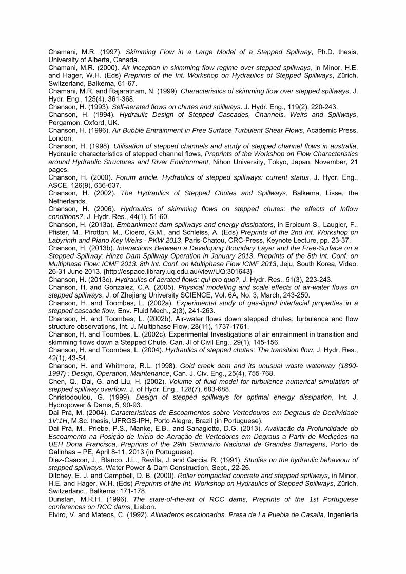
Chamani, M.R. (1997). Skimming Flow in a Large Model of a Stepped Spillway, Ph.D. thesis, University of Alberta, Canada. Chamani, M.R. (2000). Air inception in skimming flow regime over stepped spillways, in Minor, H.E. and Hager, W.H. (Eds) Preprints of the Int. Workshop on Hydraulics of Stepped Spillways, Zürich, Switzerland, Balkema, 61-67. Chamani, M.R. and Rajaratnam, N. (1999). Characteristics of skimming flow over stepped spillways, J. Hydr. Eng., 125(4), 361-368. Chanson, H. (1993). Self-aerated flows on chutes and spillways. J. Hydr. Eng., 119(2), 220-243. Chanson, H. (1994). Hydraulic Design of Stepped Cascades, Channels, Weirs and Spillways, Pergamon, Oxford, UK. Chanson, H. (1996). Air Bubble Entrainment in Free Surface Turbulent Shear Flows, Academic Press, London. Chanson, H. (1998). Utilisation of stepped channels and study of stepped channel flows in australia, Hydraulic characteristics of stepped channel flows, Preprints of the Workshop on Flow Characteristics around Hydraulic Structures and River Environment, Nihon University, Tokyo, Japan, November, 21 pages. Chanson, H. (2000). Forum article. Hydraulics of stepped spillways: current status, J. Hydr. Eng., ASCE, 126(9), 636-637. Chanson, H. (2002). The Hydraulics of Stepped Chutes and Spillways, Balkema, Lisse, the Netherlands. Chanson, H. (2006). Hydraulics of skimming flows on stepped chutes: the effects of Inflow conditions?, J. Hydr. Res., 44(1), 51-60. Chanson, H. (2013a). Embankment dam spillways and energy dissipators, in Erpicum S., Laugier, F., Pfister, M., Pirotton, M., Cicero, G.M., and Schleiss, A. (Eds) Preprints of the 2nd Int. Workshop on Labyrinth and Piano Key Weirs - PKW 2013, Paris-Chatou, CRC-Press, Keynote Lecture, pp. 23-37. Chanson, H. (2013b). Interactions Between a Developing Boundary Layer and the Free-Surface on a Stepped Spillway: Hinze Dam Spillway Operation in January 2013, Preprints of the 8th Int. Conf. on Multiphase Flow: ICMF 2013. 8th Int. Conf. on Multiphase Flow ICMF 2013, Jeju, South Korea, Video. 26-31 June 2013. {http://espace.library.uq.edu.au/view/UQ:301643} Chanson, H. (2013c). Hydraulics of aerated flows: qui pro quo?, J. Hydr. Res., 51(3), 223-243. Chanson, H. and Gonzalez, C.A. (2005). Physical modelling and scale effects of air-water flows on stepped spillways, J. of Zhejiang University SCIENCE, Vol. 6A, No. 3, March, 243-250. Chanson, H. and Toombes, L. (2002a). Experimental study of gas-liquid interfacial properties in a stepped cascade flow, Env. Fluid Mech., 2(3), 241-263. Chanson, H. and Toombes, L. (2002b). Air-water flows down stepped chutes: turbulence and flow structure observations, Int. J. Multiphase Flow, 28(11), 1737-1761. Chanson, H. and Toombes, L. (2002c). Experimental Investigations of air entrainment in transition and skimming flows down a Stepped Chute, Can. Jl of Civil Eng., 29(1), 145-156. Chanson, H. and Toombes, L. (2004). Hydraulics of stepped chutes: The transition flow, J. Hydr. Res., 42(1), 43-54. Chanson, H. and Whitmore, R.L. (1998). Gold creek dam and its unusual waste waterway (1890-1997) : Design, Operation, Maintenance, Can. J. Civ. Eng., 25(4), 755-768. Chen, Q., Dai, G. and Liu, H. (2002). Volume of fluid model for turbulence numerical simulation of stepped spillway overflow. J. of Hydr. Eng., 128(7), 683-688. Christodoulou, G. (1999). Design of stepped spillways for optimal energy dissipation, Int. J. Hydropower & Dams, 5, 90-93. Dai Prá, M. (2004). Características de Escoamentos sobre Vertedouros em Degraus de Declividade 1V:1H, M.Sc. thesis, UFRGS-IPH, Porto Alegre, Brazil (in Portuguese). Dai Prá, M., Priebe, P.S., Manke, E.B., and Sanagiotto, D.G. (2013). Avaliação da Profundidade do Escoamento na Posição de Início de Aeração de Vertedores em Degraus a Partir de Medições na UEH Dona Francisca, Preprints of the 29th Seminário Nacional de Grandes Barragens, Porto de Galinhas – PE, April 8-11, 2013 (in Portuguese). Diez-Cascon, J., Blanco, J.L., Revilla, J. and Garcia, R. (1991). Studies on the hydraulic behaviour of stepped spillways, Water Power & Dam Construction, Sept., 22-26. Ditchey, E. J. and Campbell, D. B. (2000). Roller compacted concrete and stepped spillways, in Minor, H.E. and Hager, W.H. (Eds) Preprints of the Int. Workshop on Hydraulics of Stepped Spillways, Zürich, Switzerland,. Balkema: 171-178. Dunstan, M.R.H. (1996). The state-of-the-art of RCC dams, Preprints of the 1st Portuguese conferences on RCC dams, Lisbon. Elviro, V. and Mateos, C. (1992). Aliviaderos escalonados. Presa de La Puebla de Casalla, Ingeniería
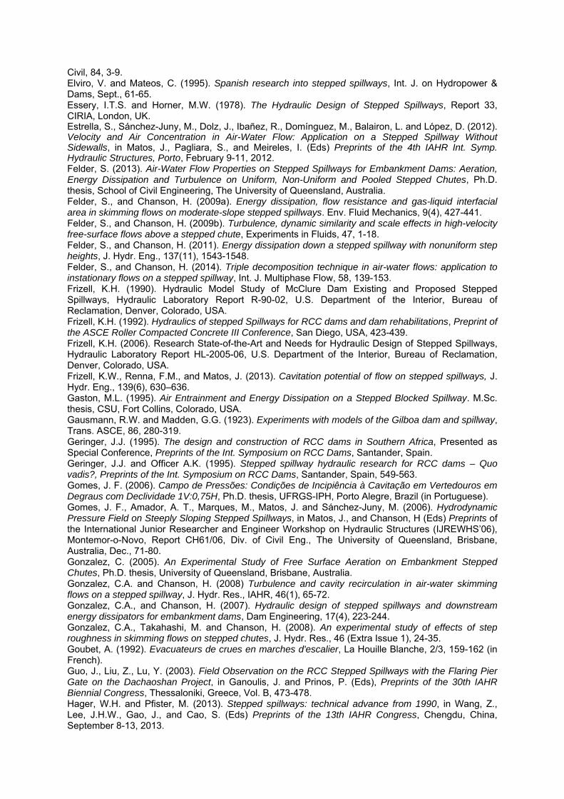
Civil, 84, 3-9. Elviro, V. and Mateos, C. (1995). Spanish research into stepped spillways, Int. J. on Hydropower & Dams, Sept., 61-65. Essery, I.T.S. and Horner, M.W. (1978). The Hydraulic Design of Stepped Spillways, Report 33, CIRIA, London, UK. Estrella, S., Sánchez-Juny, M., Dolz, J., Ibañez, R., Domínguez, M., Balairon, L. and López, D. (2012). Velocity and Air Concentration in Air-Water Flow: Application on a Stepped Spillway Without Sidewalls, in Matos, J., Pagliara, S., and Meireles, I. (Eds) Preprints of the 4th IAHR Int. Symp. Hydraulic Structures, Porto, February 9-11, 2012. Felder, S. (2013). Air-Water Flow Properties on Stepped Spillways for Embankment Dams: Aeration, Energy Dissipation and Turbulence on Uniform, Non-Uniform and Pooled Stepped Chutes, Ph.D. thesis, School of Civil Engineering, The University of Queensland, Australia. Felder, S., and Chanson, H. (2009a). Energy dissipation, flow resistance and gas-liquid interfacial area in skimming flows on moderate-slope stepped spillways. Env. Fluid Mechanics, 9(4), 427-441. Felder, S., and Chanson, H. (2009b). Turbulence, dynamic similarity and scale effects in high-velocity free-surface flows above a stepped chute, Experiments in Fluids, 47, 1-18. Felder, S., and Chanson, H. (2011). Energy dissipation down a stepped spillway with nonuniform step heights, J. Hydr. Eng., 137(11), 1543-1548. Felder, S., and Chanson, H. (2014). Triple decomposition technique in air-water flows: application to instationary flows on a stepped spillway, Int. J. Multiphase Flow, 58, 139-153. Frizell, K.H. (1990). Hydraulic Model Study of McClure Dam Existing and Proposed Stepped Spillways, Hydraulic Laboratory Report R-90-02, U.S. Department of the Interior, Bureau of Reclamation, Denver, Colorado, USA. Frizell, K.H. (1992). Hydraulics of stepped Spillways for RCC dams and dam rehabilitations, Preprint of the ASCE Roller Compacted Concrete III Conference, San Diego, USA, 423-439. Frizell, K.H. (2006). Research State-of-the-Art and Needs for Hydraulic Design of Stepped Spillways, Hydraulic Laboratory Report HL-2005-06, U.S. Department of the Interior, Bureau of Reclamation, Denver, Colorado, USA. Frizell, K.W., Renna, F.M., and Matos, J. (2013). Cavitation potential of flow on stepped spillways, J. Hydr. Eng., 139(6), 630–636. Gaston, M.L. (1995). Air Entrainment and Energy Dissipation on a Stepped Blocked Spillway. M.Sc. thesis, CSU, Fort Collins, Colorado, USA. Gausmann, R.W. and Madden, G.G. (1923). Experiments with models of the Gilboa dam and spillway, Trans. ASCE, 86, 280-319. Geringer, J.J. (1995). The design and construction of RCC dams in Southern Africa, Presented as Special Conference, Preprints of the Int. Symposium on RCC Dams, Santander, Spain. Geringer, J.J. and Officer A.K. (1995). Stepped spillway hydraulic research for RCC dams – Quo vadis?, Preprints of the Int. Symposium on RCC Dams, Santander, Spain, 549-563. Gomes, J. F. (2006). Campo de Pressões: Condições de Incipiência à Cavitação em Vertedouros em Degraus com Declividade 1V:0,75H, Ph.D. thesis, UFRGS-IPH, Porto Alegre, Brazil (in Portuguese). Gomes, J. F., Amador, A. T., Marques, M., Matos, J. and Sánchez-Juny, M. (2006). Hydrodynamic Pressure Field on Steeply Sloping Stepped Spillways, in Matos, J., and Chanson, H (Eds) Preprints of the International Junior Researcher and Engineer Workshop on Hydraulic Structures (IJREWHS’06), Montemor-o-Novo, Report CH61/06, Div. of Civil Eng., The University of Queensland, Brisbane, Australia, Dec., 71-80. Gonzalez, C. (2005). An Experimental Study of Free Surface Aeration on Embankment Stepped Chutes, Ph.D. thesis, University of Queensland, Brisbane, Australia. Gonzalez, C.A. and Chanson, H. (2008) Turbulence and cavity recirculation in air-water skimming flows on a stepped spillway, J. Hydr. Res., IAHR, 46(1), 65-72. Gonzalez, C.A., and Chanson, H. (2007). Hydraulic design of stepped spillways and downstream energy dissipators for embankment dams, Dam Engineering, 17(4), 223-244. Gonzalez, C.A., Takahashi, M. and Chanson, H. (2008). An experimental study of effects of step roughness in skimming flows on stepped chutes, J. Hydr. Res., 46 (Extra Issue 1), 24-35. Goubet, A. (1992). Evacuateurs de crues en marches d'escalier, La Houille Blanche, 2/3, 159-162 (in French). Guo, J., Liu, Z., Lu, Y. (2003). Field Observation on the RCC Stepped Spillways with the Flaring Pier Gate on the Dachaoshan Project, in Ganoulis, J. and Prinos, P. (Eds), Preprints of the 30th IAHR Biennial Congress, Thessaloniki, Greece, Vol. B, 473-478. Hager, W.H. and Pfister, M. (2013). Stepped spillways: technical advance from 1990, in Wang, Z., Lee, J.H.W., Gao, J., and Cao, S. (Eds) Preprints of the 13th IAHR Congress, Chengdu, China, September 8-13, 2013.
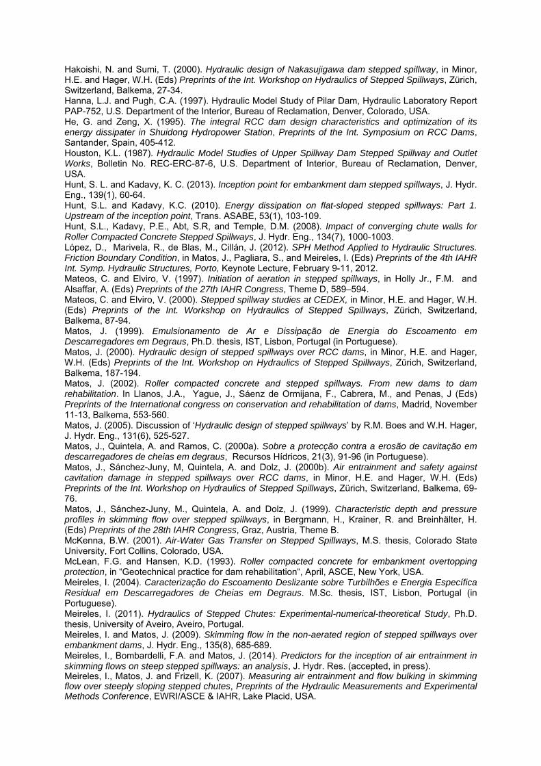
Hakoishi, N. and Sumi, T. (2000). Hydraulic design of Nakasujigawa dam stepped spillway, in Minor, H.E. and Hager, W.H. (Eds) Preprints of the Int. Workshop on Hydraulics of Stepped Spillways, Zürich, Switzerland, Balkema, 27-34. Hanna, L.J. and Pugh, C.A. (1997). Hydraulic Model Study of Pilar Dam, Hydraulic Laboratory Report PAP-752, U.S. Department of the Interior, Bureau of Reclamation, Denver, Colorado, USA. He, G. and Zeng, X. (1995). The integral RCC dam design characteristics and optimization of its energy dissipater in Shuidong Hydropower Station, Preprints of the Int. Symposium on RCC Dams, Santander, Spain, 405-412. Houston, K.L. (1987). Hydraulic Model Studies of Upper Spillway Dam Stepped Spillway and Outlet Works, Bolletin No. REC-ERC-87-6, U.S. Department of Interior, Bureau of Reclamation, Denver, USA. Hunt, S. L. and Kadavy, K. C. (2013). Inception point for embankment dam stepped spillways, J. Hydr. Eng., 139(1), 60-64. Hunt, S.L. and Kadavy, K.C. (2010). Energy dissipation on flat-sloped stepped spillways: Part 1. Upstream of the inception point, Trans. ASABE, 53(1), 103-109. Hunt, S.L., Kadavy, P.E., Abt, S.R, and Temple, D.M. (2008). Impact of converging chute walls for Roller Compacted Concrete Stepped Spillways, J. Hydr. Eng., 134(7), 1000-1003. López, D., Marivela, R., de Blas, M., Cillán, J. (2012). SPH Method Applied to Hydraulic Structures. Friction Boundary Condition, in Matos, J., Pagliara, S., and Meireles, I. (Eds) Preprints of the 4th IAHR Int. Symp. Hydraulic Structures, Porto, Keynote Lecture, February 9-11, 2012. Mateos, C. and Elviro, V. (1997). Initiation of aeration in stepped spillways, in Holly Jr., F.M. and Alsaffar, A. (Eds) Preprints of the 27th IAHR Congress, Theme D, 589–594. Mateos, C. and Elviro, V. (2000). Stepped spillway studies at CEDEX, in Minor, H.E. and Hager, W.H. (Eds) Preprints of the Int. Workshop on Hydraulics of Stepped Spillways, Zürich, Switzerland, Balkema, 87-94. Matos, J. (1999). Emulsionamento de Ar e Dissipação de Energia do Escoamento em Descarregadores em Degraus, Ph.D. thesis, IST, Lisbon, Portugal (in Portuguese). Matos, J. (2000). Hydraulic design of stepped spillways over RCC dams, in Minor, H.E. and Hager, W.H. (Eds) Preprints of the Int. Workshop on Hydraulics of Stepped Spillways, Zürich, Switzerland, Balkema, 187-194. Matos, J. (2002). Roller compacted concrete and stepped spillways. From new dams to dam rehabilitation. In Llanos, J.A., Yague, J., Sáenz de Ormijana, F., Cabrera, M., and Penas, J (Eds) Preprints of the International congress on conservation and rehabilitation of dams, Madrid, November 11-13, Balkema, 553-560. Matos, J. (2005). Discussion of ‘Hydraulic design of stepped spillways’ by R.M. Boes and W.H. Hager, J. Hydr. Eng., 131(6), 525-527. Matos, J., Quintela, A. and Ramos, C. (2000a). Sobre a protecção contra a erosão de cavitação em descarregadores de cheias em degraus, Recursos Hídricos, 21(3), 91-96 (in Portuguese). Matos, J., Sánchez-Juny, M, Quintela, A. and Dolz, J. (2000b). Air entrainment and safety against cavitation damage in stepped spillways over RCC dams, in Minor, H.E. and Hager, W.H. (Eds) Preprints of the Int. Workshop on Hydraulics of Stepped Spillways, Zürich, Switzerland, Balkema, 69-76. Matos, J., Sánchez-Juny, M., Quintela, A. and Dolz, J. (1999). Characteristic depth and pressure profiles in skimming flow over stepped spillways, in Bergmann, H., Krainer, R. and Breinhälter, H. (Eds) Preprints of the 28th IAHR Congress, Graz, Austria, Theme B. McKenna, B.W. (2001). Air-Water Gas Transfer on Stepped Spillways, M.S. thesis, Colorado State University, Fort Collins, Colorado, USA. McLean, F.G. and Hansen, K.D. (1993). Roller compacted concrete for embankment overtopping protection, in “Geotechnical practice for dam rehabilitation“, April, ASCE, New York, USA. Meireles, I. (2004). Caracterização do Escoamento Deslizante sobre Turbilhões e Energia Específica Residual em Descarregadores de Cheias em Degraus. M.Sc. thesis, IST, Lisbon, Portugal (in Portuguese). Meireles, I. (2011). Hydraulics of Stepped Chutes: Experimental-numerical-theoretical Study, Ph.D. thesis, University of Aveiro, Aveiro, Portugal. Meireles, I. and Matos, J. (2009). Skimming flow in the non-aerated region of stepped spillways over embankment dams, J. Hydr. Eng., 135(8), 685-689. Meireles, I., Bombardelli, F.A. and Matos, J. (2014). Predictors for the inception of air entrainment in skimming flows on steep stepped spillways: an analysis, J. Hydr. Res. (accepted, in press). Meireles, I., Matos, J. and Frizell, K. (2007). Measuring air entrainment and flow bulking in skimming flow over steeply sloping stepped chutes, Preprints of the Hydraulic Measurements and Experimental Methods Conference, EWRI/ASCE & IAHR, Lake Placid, USA.
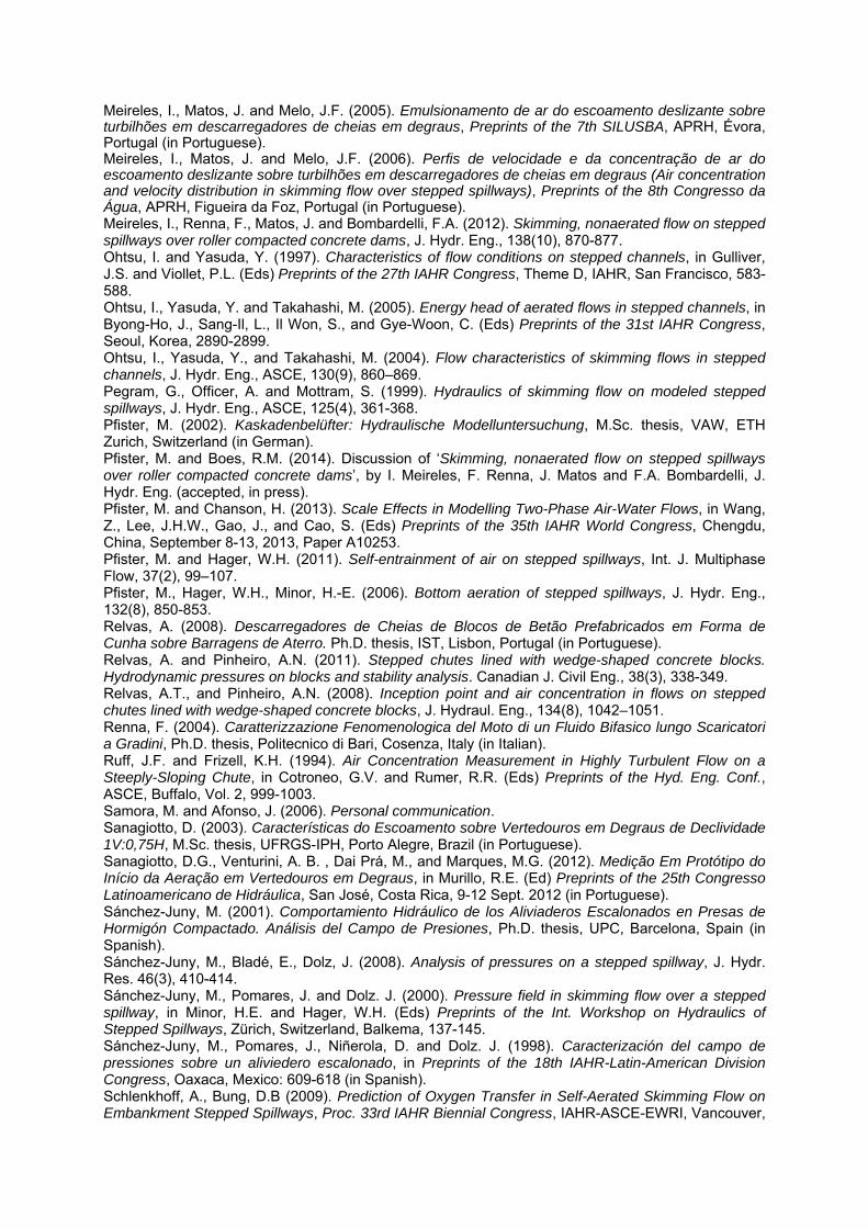
Meireles, I., Matos, J. and Melo, J.F. (2005). Emulsionamento de ar do escoamento deslizante sobre turbilhões em descarregadores de cheias em degraus, Preprints of the 7th SILUSBA, APRH, Évora, Portugal (in Portuguese). Meireles, I., Matos, J. and Melo, J.F. (2006). Perfis de velocidade e da concentração de ar do escoamento deslizante sobre turbilhões em descarregadores de cheias em degraus (Air concentration and velocity distribution in skimming flow over stepped spillways), Preprints of the 8th Congresso da Água, APRH, Figueira da Foz, Portugal (in Portuguese). Meireles, I., Renna, F., Matos, J. and Bombardelli, F.A. (2012). Skimming, nonaerated flow on stepped spillways over roller compacted concrete dams, J. Hydr. Eng., 138(10), 870-877. Ohtsu, I. and Yasuda, Y. (1997). Characteristics of flow conditions on stepped channels, in Gulliver, J.S. and Viollet, P.L. (Eds) Preprints of the 27th IAHR Congress, Theme D, IAHR, San Francisco, 583-588. Ohtsu, I., Yasuda, Y. and Takahashi, M. (2005). Energy head of aerated flows in stepped channels, in Byong-Ho, J., Sang-Il, L., Il Won, S., and Gye-Woon, C. (Eds) Preprints of the 31st IAHR Congress, Seoul, Korea, 2890-2899. Ohtsu, I., Yasuda, Y., and Takahashi, M. (2004). Flow characteristics of skimming flows in stepped channels, J. Hydr. Eng., ASCE, 130(9), 860–869. Pegram, G., Officer, A. and Mottram, S. (1999). Hydraulics of skimming flow on modeled stepped spillways, J. Hydr. Eng., ASCE, 125(4), 361-368. Pfister, M. (2002). Kaskadenbelüfter: Hydraulische Modelluntersuchung, M.Sc. thesis, VAW, ETH Zurich, Switzerland (in German). Pfister, M. and Boes, R.M. (2014). Discussion of ‘Skimming, nonaerated flow on stepped spillways over roller compacted concrete dams’, by I. Meireles, F. Renna, J. Matos and F.A. Bombardelli, J. Hydr. Eng. (accepted, in press). Pfister, M. and Chanson, H. (2013). Scale Effects in Modelling Two-Phase Air-Water Flows, in Wang, Z., Lee, J.H.W., Gao, J., and Cao, S. (Eds) Preprints of the 35th IAHR World Congress, Chengdu, China, September 8-13, 2013, Paper A10253. Pfister, M. and Hager, W.H. (2011). Self-entrainment of air on stepped spillways, Int. J. Multiphase Flow, 37(2), 99–107. Pfister, M., Hager, W.H., Minor, H.-E. (2006). Bottom aeration of stepped spillways, J. Hydr. Eng., 132(8), 850-853. Relvas, A. (2008). Descarregadores de Cheias de Blocos de Betão Prefabricados em Forma de Cunha sobre Barragens de Aterro. Ph.D. thesis, IST, Lisbon, Portugal (in Portuguese). Relvas, A. and Pinheiro, A.N. (2011). Stepped chutes lined with wedge-shaped concrete blocks. Hydrodynamic pressures on blocks and stability analysis. Canadian J. Civil Eng., 38(3), 338-349. Relvas, A.T., and Pinheiro, A.N. (2008). Inception point and air concentration in flows on stepped chutes lined with wedge-shaped concrete blocks, J. Hydraul. Eng., 134(8), 1042–1051. Renna, F. (2004). Caratterizzazione Fenomenologica del Moto di un Fluido Bifasico lungo Scaricatori a Gradini, Ph.D. thesis, Politecnico di Bari, Cosenza, Italy (in Italian). Ruff, J.F. and Frizell, K.H. (1994). Air Concentration Measurement in Highly Turbulent Flow on a Steeply-Sloping Chute, in Cotroneo, G.V. and Rumer, R.R. (Eds) Preprints of the Hyd. Eng. Conf., ASCE, Buffalo, Vol. 2, 999-1003. Samora, M. and Afonso, J. (2006). Personal communication. Sanagiotto, D. (2003). Características do Escoamento sobre Vertedouros em Degraus de Declividade 1V:0,75H, M.Sc. thesis, UFRGS-IPH, Porto Alegre, Brazil (in Portuguese). Sanagiotto, D.G., Venturini, A. B. , Dai Prá, M., and Marques, M.G. (2012). Medição Em Protótipo do Início da Aeração em Vertedouros em Degraus, in Murillo, R.E. (Ed) Preprints of the 25th Congresso Latinoamericano de Hidráulica, San José, Costa Rica, 9-12 Sept. 2012 (in Portuguese). Sánchez-Juny, M. (2001). Comportamiento Hidráulico de los Aliviaderos Escalonados en Presas de Hormigón Compactado. Análisis del Campo de Presiones, Ph.D. thesis, UPC, Barcelona, Spain (in Spanish). Sánchez-Juny, M., Bladé, E., Dolz, J. (2008). Analysis of pressures on a stepped spillway, J. Hydr. Res. 46(3), 410-414. Sánchez-Juny, M., Pomares, J. and Dolz. J. (2000). Pressure field in skimming flow over a stepped spillway, in Minor, H.E. and Hager, W.H. (Eds) Preprints of the Int. Workshop on Hydraulics of Stepped Spillways, Zürich, Switzerland, Balkema, 137-145. Sánchez-Juny, M., Pomares, J., Niñerola, D. and Dolz. J. (1998). Caracterización del campo de pressiones sobre un aliviedero escalonado, in Preprints of the 18th IAHR-Latin-American Division Congress, Oaxaca, Mexico: 609-618 (in Spanish). Schlenkhoff, A., Bung, D.B (2009). Prediction of Oxygen Transfer in Self-Aerated Skimming Flow on Embankment Stepped Spillways, Proc. 33rd IAHR Biennial Congress, IAHR-ASCE-EWRI, Vancouver,
Canada, 9-14 Aug., pp. 4151-4158. Silva, J. and Ramos, I. (2001). Barragem de Pedrógão. Concepção dos Órgãos Hidráulicos. Presentation notes, technical course, Concepção e Dimensionamento de Obras Hidráulicas com Soleira em Degraus, FUNDEC – DECIVIL, IST, April 18-19, 2001, IST (in Portuguese). Silvestri, A., Archambeau, P., Pirotton, M., Dewals, B. and Erpicum, S. (2013b). Comparative Analysis of the Energy Dissipation on a Stepped Spillways Downstream of a Piano Key Weir, in Erpicum S., Laugier, F., Pfister, M., Pirotton, M., Cicero, G.M., and Schleiss, A. (Eds) Preprints of the 2nd Int. Workshop on Labyrinth and Piano Key Weirs - PKW 2013, CRC Press, Paris-Chatou, 111-120. Silvestri, A., Erpicum, S., Archambeau, P., Dewals, B. and Pirotton, M. (2013a). Stepped Spillway Downstream of a Piano Key Weir – Critical Length for Uniform Flow, in Bung, D., and Pagliara, S. (Eds), Preprints of the International Workshop on Hydraulic Design of Low-Head Structures, Bundesanstalt für Wasserbau (BAW, Karlsruhe), Aachen, Germany, 77-86. Simões, A.L., Schulz, H.E. and Porto, R.M. (2008). Stepped and smooth spillways: resistance effects on stilling basin lengths, J. Hydr. Res., IAHR, 48(3), 329-337. Simões, A.L., Schulz, H.E., Lobosco, R.J. and Porto, R.M. (2012). Stepped Spillways: Theoretical, Experimental and Numerical Studies, in “Hydrodynamics-Natural Water Bodies”, Schulz, H.E., Simões, A.L., Lobosco, R.J. (Eds), InTech, 2012, 237-262. Sorensen, R.M. (1985). Stepped spillway hydraulic model investigation, J. Hydr. Eng., 111(12), 1461–1472. Stephenson, D. (1979). Gabion energy dissipators, Preprints of the 13th ICOLD Congress, New Delhi, Q50(R3), 33-43. Takahashi, M., and Ohtsu, I. (2012). Aerated flow characteristics of skimming flow over stepped chutes, J. Hydr. Res., 50(1), 51-60. Thorwarth, J. (2008). Hydraulisches Verhalten der Treppengerinne mit eingetieften Stufen – Selbstinduzierte Abflussinstationaritäten und Energiedissipation (Hydraulics of Pooled Stepped Spillways – Self-induced Unsteady Flow and Energy Dissipation.) Ph.D. thesis, University of Aachen, Germany (in German). Thorwarth, J., and Köngeter, J. (2006). Physical model test on a stepped chute with pooled steps – investigation of flow resistance and flow instabilities, in Marcano, A. and Martinez, A. (Eds) Preprints of the Int. Symposium on Hydraulic Structures, Ciudad Guayana, Venezuela, 477-486. Toombes, L. (2002). Experimental Study of Air-water Flow Properties on Low-gradient Stepped Cascades, Ph.D. thesis, Department of Civil Engineering, University of Queensland, Brisbane, Australia. Toombes, L., and Chanson, H. (2005). Air-water mass transfer on a stepped waterway. J. Env. Eng., 131(10), 1377-1386. Tozzi, M.J. (1992). Caracterização/Comportamento de Escoamentos em Vertedouros com Paramento em Degraus, Ph.D. thesis, Escola Politécnica da Universidade de São Paulo, São Paulo, Brazil (in Portuguese). Ward (2002). Hydraulic Design of Stepped Spillways, Ph.D. thesis, Colorado State University, Fort Collins, Colorado, USA. Wark, R.J., Kerby, N.E. and Mann, G.B. (1991). New Victoria dam project, ANCOLD Bulletin, 88, 14-32. Wegmann, E. (1911). The Design and Construction of Dams, Including Masonry, Earth, Rock-Fill, Timber, and Steel Structures, Wiley, New York. Willey, J., Ewing, T., Lesleighter, E., and Dymke, J. (2010). Numerical and physical modeling for a complex stepped spillway, Hydropower & Dams, 3, 103-113. Wood, I.R. (1985). Air-water flows, Preprints of the 21st IAHR Congress, Melbourne, Australia, Keynote Address, pp. 18-29. Wood, I.R. (1991). Free surface air entrainment on spillways, in Wood, I.R. “Air entrainment in free-surface flows”, IAHR, Hydraulic Structures Design Manual 4, Hydraulic Design Considerations, A. A. Balkema, Rotterdam, the Netherlands, 55–84. Yasuda, Y. and Chanson, H. (2003). Micro- and macro-scopic study of two-phase flow on a stepped chute, in J. Ganoulis and P. Prinos (Eds) Preprints of the 30th IAHR Congress, Thessaloniki, Greece, 695-702. Yasuda, Y. and Othsu, I. (1999). Flow resistance of skimming flow in stepped channels, in Bergmann, H., Krainer, R. and Breinhälter, H. (Eds) Preprints of the 28th IAHR Congress, Graz, Austria, Session B14. Young, M.F. (1982). Feasibility study of a stepped spillway, in Smith, P.E. “Applying research to hydraulic practice”, ASCE, New York, 96-105. Zamora, A.S., Pfister, M., Hager, W.H., Minor, H.-E. (2008). Hydraulic performance of step aerator. J.

Hydr. Eng., 134(2), 127-134.


![Welcome [cercind.gov.in]cercind.gov.in/November08/PPT-MEETING3.11.2008/THDC/THDC.pdf · complete dam, spillways and other civil structures and also after the complete installation](https://img.pdfslide.us/doc/110x75/5f1b89d4f3858911b27048ba/welcome-complete-dam-spillways-and-other-civil-structures-and-also-after-the.jpg)