Embed Size (px)
Citation preview
CHANSON, H. (2000). "A Review of Accidents and Failures of Stepped Spillways and Weirs." Proc. Instn Civ. Engrs Water and Maritime Engrg, UK, Vol. 142, Dec., pp. 177-188 (ISSN 0965-0946).
A REVIEW OF ACCIDENTS AND FAILURES OF STEPPED SPILLWAYS AND WEIRS
by Hubert CHANSON
Senior Lecturer, Fluid Mechanics, Hydraulics and Environmental Engineering
Department of Civil Engineering, The University of Queensland, Brisbane QLD 4072, Australia
Fax : (61 7) 33 65 45 99 - Email : [email protected]
SYNOPSIS
Recent advances in technology have permitted the construction of large reservoirs and chutes. These developments
have necessitated the development of new design and construction techniques, particularly with the provision of
adequate flood release facilities and safe energy dissipation. The latter may be achieved by the construction of steps on
the chute. This paper discusses the issues of operation and safe design of stepped chutes. It describes the operation of
several structures worldwide focusing on accidents and failures. The causes of failures are analysed and discussed.
Problems specific to stepped chute design are discussed in the light of over 20 accidents and common mistakes are
elaborated. The safe operation of several old stepped chutes and the experience learned from past failures must be used
to gain further expertise and knowledge on the hydraulics of stepped chutes.
Keywords : Hydraulics & hydrodynamics; Dams, barrages & reservoirs; Water supply.
NOTATION
dc critical flow depth (m);
Hdam dam height (m);
h step height (m);
l step length (m);
Qdes design discharge (m3/s);
Qw water discharge (m3/s);
qdes design discharge per unit width (m2/s);
qw water discharge per unit width (m2/s);
W channel width (m);
θ slope of the pseudo-bottom formed by step edges.
INTRODUCTION
Stepped channels and spillways have been used for more than 3,000 years (CHANSON 1995, 1997). The development
of new construction materials such as roller compacted concrete (RCC) and strengthened gabions has created a renewed
interest in stepped chutes. The steps increase the rate of energy dissipation along the chute and reduce the size of the
CHANSON, H. (2000). "A Review of Accidents and Failures of Stepped Spillways and Weirs." Proc. Instn Civ. Engrs Water and Maritime Engrg, UK, Vol. 142, Dec., pp. 177-188 (ISSN 0965-0946).
required downstream energy dissipation basin. Stepped cascades are used also for in-stream re-aeration and removal of
volatile organic components (VOC) in water treatment plants.
Satisfactory performances of stepped cascades were acknowledged in classical textbooks (e.g. HUMBER 1876,
SCHUYLER 1909, WEGMANN 1922). Recently the operation of modern RCC structures has attracted some attention.
The Shuidong dam, a 57-m high RCC dam in China, was equipped with a 60-m wide stepped chute (h = 0.9 m, θ = 57º)
designed for 6,012 m3/s. In May 1994, the stepped chute discharged up to 90 m2/s (or 90 m3/m/s) successfully and the
event was videotaped (HE and ZENG 1995). The Ocoee dam No. 2, a timber crib structure with downstream RCC
buttresses, is intentionally overtopped for river rafting over 82 times per year. In 1990, the structure passed adequately
a flood (qw = 11.9 m2/s) (HANSEN and McLEAN 1995). Despite the successes, little attention has been paid to basic
safety issues. JANSEN (1983) discussed generally the problem of public safety. GOUBET (1992) and CHANSON
(1995) argued critically for and against the stepped chute design.
The present paper reviews the operation of stepped channels with an emphasis on accidents, incidents and failures. The
purpose of the paper is to provide a critical review of the overall experience on this field, to alert professional engineers
of potential engineering failures, and to recommend safer design and operation methods.
Stepped channel hydraulics
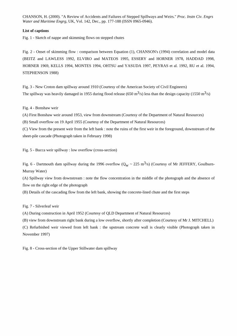
Stepped channels may be characterised by two types of flow : nappe flow and skimming flow (Fig. 1) (e.g.
RAJARATNAM 1990, CHANSON 1994). At low flow rates and for relatively large step height, the water flows from
one step onto another as a succession of free-falling nappes (i.e. nappe flow). At larger flow rates, the flow skims over
the step edges with the formation of recirculating vortices between the main stream and the step corners. The hydraulic
characteristics differ significantly between each regime (CHANSON 1995).
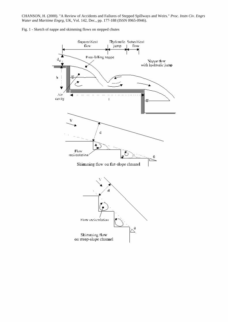
The transition between nappe and skimming flow is related to the flow rate, chute slope, step geometry and local flow
properties at each step. The re-analysis of a large number of model data provides an updated limiting condition for
skimming flow :
dch > 1.1 - 0.40 *
hl Skimming flow condition (1)
where dc is the critical flow depth, h is the height and l is the step length (Fig. 2). Equation (1) is limited to flat
horizontal steps for h/l ranging from 0.15 to 1.4 and it characterises the onset of skimming flow for uniform or quasi-
uniform equilibrium flows down prismatic rectangular channels. Its accuracy is within +/- 30% (Fig. 2). For
accelerating or decelerating flows (i.e. rapidly varied flows), Equation (1) is inaccurate and a more complete analysis is
required (e.g. CHANSON 1996).
OPERATION, ACCIDENTS, INCIDENTS AND FAILURES
Over the past two hundred years, at least 20 accidents or failures involved hydraulic structures equipped with stepped
spillways (Table 1). Although two failures, Puentes and St Francis dams, were unrelated to the spillway operation,
several accidents were caused by the selection of a stepped design (e.g. New Croton dam, Fig. 3). CHANSON (1995)
described in detail some of these cases. Further details of accidents and failures, listed in Table 1, are presented below
in alphabetical order.
CHANSON, H. (2000). "A Review of Accidents and Failures of Stepped Spillways and Weirs." Proc. Instn Civ. Engrs Water and Maritime Engrg, UK, Vol. 142, Dec., pp. 177-188 (ISSN 0965-0946).
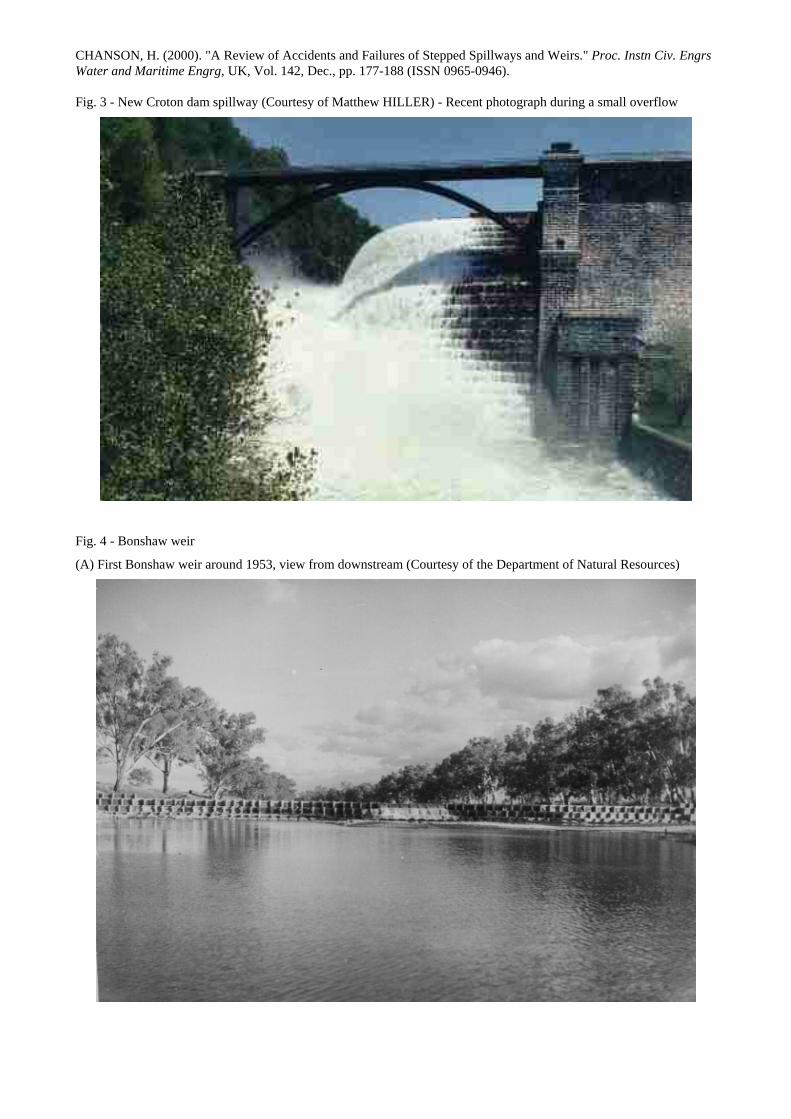
Bonshaw weir (Australia)
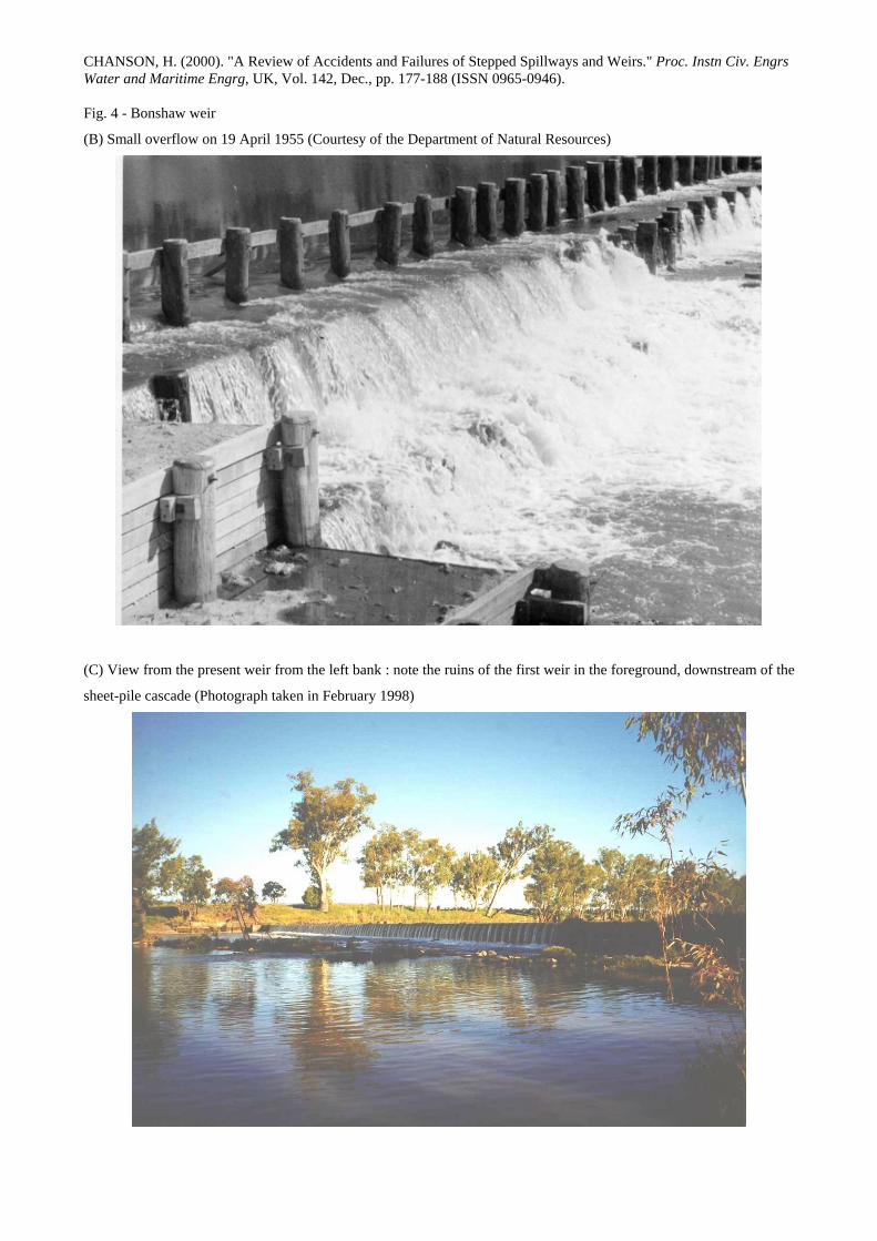
The (first) Bonshaw weir was completed in May 1953 (Fig. 4). Located on the Dumaresq river, it was designed for
irrigation water, the primary industry being tobacco. The 3.7-m high weir was a timber crib piled structure (144.5-m
long), designed with 4 steps (h = 0.9 m).
A major flood occurred in January and early February 1956. Intense rainfall was recorded in the catchment (e.g. 185
mm on 21 January and 225 mm on 22 January 1956 at nearby Columba) and the river was in flood for about 2 months.
The maximum recorded stream heights were 11.13 m in January and 8.76 m in February at Cunningham located 60 km
downstream. The nearby town of Texas was flooded and inhabitants could not cross the river for several weeks.
The failure of the Bonshaw weir occurred during the overflow event. Both abutments failed. The left abutment was
bypassed and it was heavily scoured. The right abutment and a section of the weir were washed away. The failure
resulted from an average quality of construction and poor abutment foundations.
In 1958, a new weir was built, at the same site, in steel sheet-piles and concrete (Fig. 4(C)). Interestingly the new weir
is only 2.4-m high and it is shorter than the first weir.
It is worth comparing the operation of the (1st) Bonshaw weir with that of the Cunningham weir, another timber crib
piled weir located 60-km downstream. Completed in 1954, the Cunningham weir suffered only minor damage during
the 1956 flood. It is still in use and in good condition today.
Bucca weir (Australia)
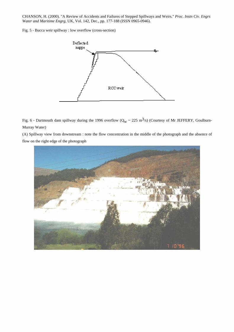
Completed in 1987, the Bucca weir is a 12-m high RCC weir equipped with an overflow stepped spillway (Fig. 5). The
design is an inclined-upward broad-crest followed by a 1.6-m drop and seventeen 0.6-m high steps (h/l = 2). The
maximum design discharge is 7,250 m3/s.
Shortly after completion, loud noises were heard during low overflows. At the brink of the first step (i.e. downstream
end of crest), the water was deflected away from the chute as a free-falling nappe and the air cavity was not ventilated.
Nappe instabilities developed and generated low-frequency vibrations to the structure and loud noises that were not
acceptable to nearby residents.
The problem was remedied by the installation of splitters on the crest edge to ventilate the nappe at low-flows. The
splitter devices are tiltable and drop at medium to large overflows.
Dartmouth dam (Australia)
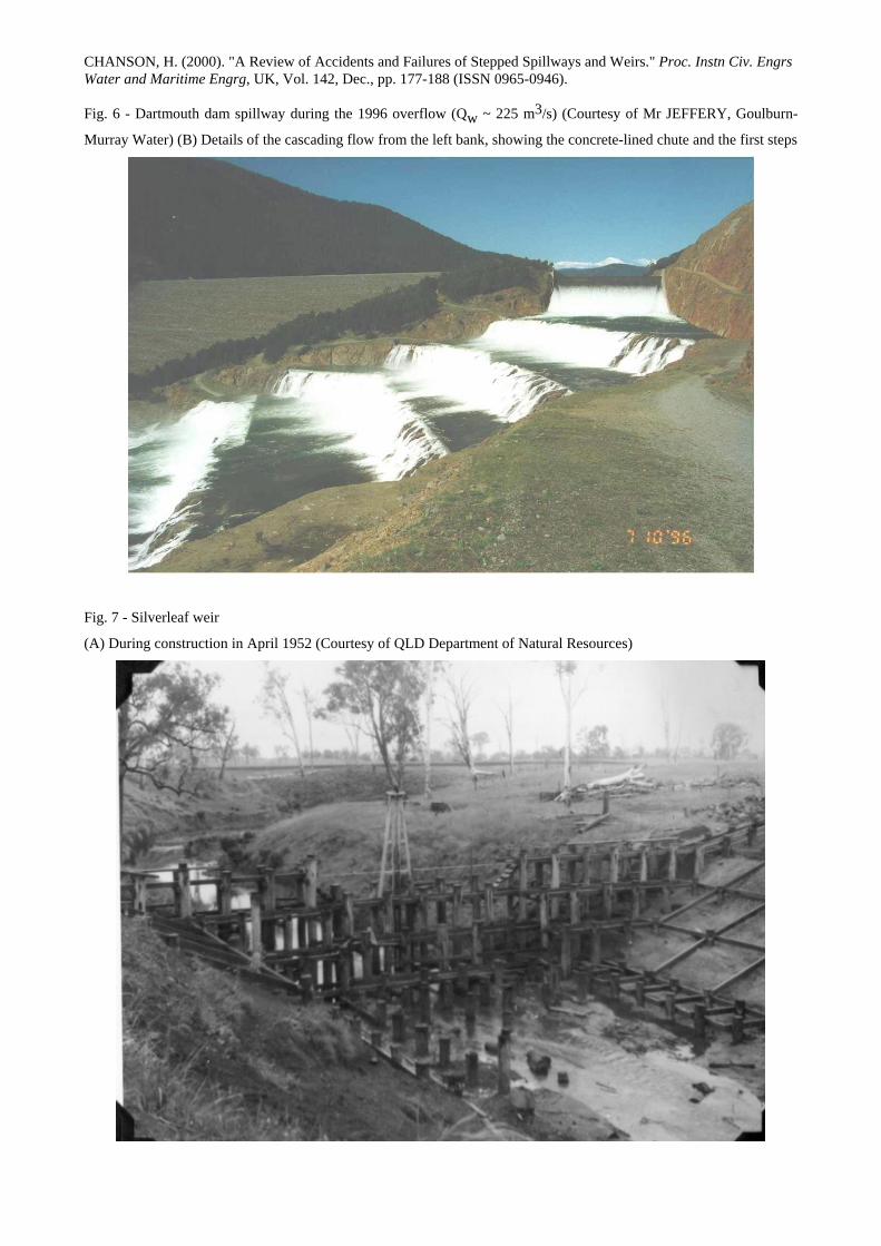
Completed in 1977, the Dartmouth dam is a 180-m high earth and rockfill structure (Fig. 6). The spillway, located on
the left bank, consists of an approach channel, a concrete-lined crest and chute (width: 91.4 m) followed by a 10-step
unlined rock cascade (h = 15 m, W = 300 to 350 m). The rock is granitic gneiss and the step excavation was used for
the dam rockfill. The design discharge capacity is 2,755 m3/s.
During the 1996 flood (Qw ≈ 225 m3/s), the unlined rock spillway was partially damaged. Although the discharge was
much lower than the design flow rate, significant erosion was observed at several steps because of flow concentration
in the right side of the cascade.
Repairs were undertaken in 1996 and 1997 that included the provision of shotcrete protection and construction of
anchored concrete retaining walls in the three upstream steps. Walls were built to prevent concentration of low-level
flows in some areas.
CHANSON, H. (2000). "A Review of Accidents and Failures of Stepped Spillways and Weirs." Proc. Instn Civ. Engrs Water and Maritime Engrg, UK, Vol. 142, Dec., pp. 177-188 (ISSN 0965-0946).
It is worth comparing the Dartmouth dam spillway characteristics with those of other unlined rock cascades (Table 2).
Overall the maximum discharge capacity is lower than at La Grande 2 cascade, but the step height is one of the largest,
leading to high nappe-impact velocities in excess of 17 m/s. For large impact velocities, deep pools of water are
required to cushion the jet impact pressures on the rock.
Hilliard Creek weir (Australia)
The weir was completed in 1948 on Hilliard Creek, less than 1 km from the estuary. It was built for water supply and to
prevent salt intrusion. The 3.4-m high weir is a timber crib piled structure. Repaired once in 1963, the weir is now in
ruins because of the lack of maintenance. The timber crib skeleton and some rockfill are visible showing the
construction technique but the weir is not holding water : i.e., it is porous.
Warning signs are posted around the weir indicating that it is unsafe to approach or to walk on the structure.
Surprisingly the weir was still listed in an 1997 annual report of the Queensland state government.
Kobila dam (Slovenia)
The Kobila dam was a timber crib structure filled with rocks. Built in 1586 across the Idrijca river, the dam was over
10-m high and the crest length was about 20-m (BREZNIK 1984). The structure was equipped with an overflow
stepped spillway. The spillway crest was protected from floating logs with wooden planks.
The dam operated continuously up to 1948 when it was destroyed by a flood after 362 years of operation. During
World War II and the subsequent years, the dam was not maintained. It is believed that the failure resulted from the
lack of maintenance and care for nearly ten years.
Moscovite earth dams (Russia)
Between 1940 and 1980, Soviet engineers developed the concept of overflow earth dams (prior to the introduction of
roller compacted concrete) under the leadership of Professor P.I. GORDIENKO (1944, 1978). The spillway design
consists of a trapezoidal channel made of precast concrete blocks laid on the downstream slope of the embankment. A
protective drainage layer must be installed between the earthfill and the blocks to prevent seepage during overflows.
In 1978 five overflow embankments were built in the Moscow region (PRAVDIVETS 1992). The dams were about 7
to 15 m high. Each spillway system comprised an overflow with precast concrete blocks (about 60 to 120 kg each) and
it was designed to pass between 30 to 60 m3/s.
Two structures failed during the first year of operation. Their protective layer did not perform adequately and the
earthen embankments were eroded. In one case (i.e. Zhilevski dam), the smallest stone size of the drainage layer was
smaller than the drainage holes in the concrete blocks. In absence of a geotextile fabric, drainage layer material and
earthfill were sucked into the drainage holes and washed away during a storm leading to the failure.
Lahontan dam (USA)
Built in 1915, the Lahontan dam is a 49-m high earth structure across the Carson river (Nevada). The dam is owned by
the US Bureau of Reclamation. It is equipped with two stepped spillways on the left and right abutments. The
maximum discharge capacity is 424.8 m3/s per spillway. The right spillway consists of two drops followed by a long
curved flat chute with converging walls leading to a series of 7 steps (h = 3.35 m, θ = 22.9º, W = 45.72 m). The left
spillway consists of a series of 6 steps (h = 3.05 m, θ = 26.6º, W = 76.3 m), a converging flat chute section and a
CHANSON, H. (2000). "A Review of Accidents and Failures of Stepped Spillways and Weirs." Proc. Instn Civ. Engrs Water and Maritime Engrg, UK, Vol. 142, Dec., pp. 177-188 (ISSN 0965-0946).
curved stepped channel (3 steps, h = 3.05 m, l = 6.096 m, W = 45.72 m) with a curvature radius ranging from 39 to 50
m. The right and left spillways meet in a circular stilling basin at the dam toe.
In the late 1930s, the concrete of the spillways was in poor condition, particularly in the right spillway, although only
two floods had been recorded since construction (DOUMA and GOODPASTURE 1940). It was suggested that the
concrete construction was damaged by freeze and thawing (JANSEN 1983). Hydraulic tests showed that a hydraulic
jump took place at the end of the flat chutes (DOUMA and GOODPASTURE 1940). A re-analysis shows further that
the right spillway could experience a transition flow nappe-skimming at maximum flow rate (dc/h = 0.62). It is thought
that the spillway damage was initiated by scour associated with the presence of hydraulic jumps and further enhanced
by flow instabilities at the transition between nappe flow and skimming flow in the right spillway.
Narora weir (India)
Completed in 1877, the Narora weir was part of the Lower Ganges canal. It was a 3.05-m high 1,160-m long drop
structure built in brick works (BUCKLEY 1905). It was designed to pass 3,400 m3/s.
The weir failed in March 1898. Concrete and stonework of the stilling basin were damaged over a 107-m wide section.
The weir was discharging 13,800 m3/s at the time of failure : i.e., four times the design flow rate !
The weir was strengthened in 1898 and 1899.
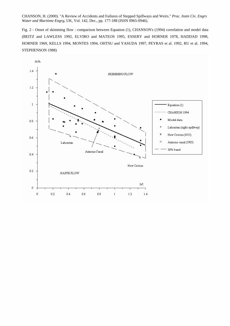
New Croton dam (USA)
Completed in 1906, the New Croton dam was the highest dam in the world at that time (Fig. 3). It was designed to
supply water to the city of New York and it still does. The spillway was designed with a stepped geometry to
specifically dissipate the energy of the flow (Qdes = 1,550 m3/s) (WEGMANN 1907). The dam was built of concrete
and the stepped chute was protected with granite blocks (step geometry : h = 2.13 m, l = 1.6 m).
In October 1955, the spillway was heavily damaged during a 650 m3/s overflow. Extensive repairs were carried out
between 1955 and 1957 (MARSH 1957), and the stepped chute is still used.
The spillway damage was caused by an improper spillway intake and, further, overflow conditions at the transition
between nappe and skimming flow aggravated the severity of the damage (CHANSON 1995).
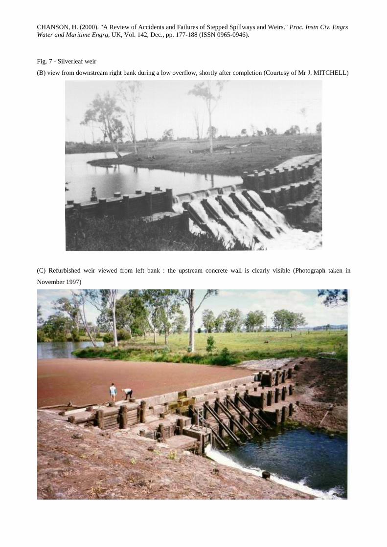
Silverleaf weir (Australia)
The Silverleaf weir was built between 1951 and 1953 for stock water. The 5.1-m high weir was designed as a timber
crib piled weir with concrete protection of the four steps (Fig. 7). The upstream wall was sealed with a clay
embankment held by boulders set in mortar. The weir was refurbished in 1995 with the installation of a new outlet,
construction of an upstream vertical concrete wall to replace the clay fill and to heighten the weir crest by an additional
concrete step, and construction of a counterweir downstream.
During the refurbishment, an earthfill cofferdam was built 20-m upstream to de-water the weir. A flood event took
place while the weir was dry and the clayfill was removed. The cofferdam was overtopped on 7 February 1995 and the
resulting flood wave submerged the weir. The weir was overtopped by over 1-m of water and overtopping lasted for 24
hours, with seepage through the timber cribs for a further 12 hours before repairs could start. After the event,
inspections showed that the weir sustained the flood wave without major damage. The overtopping was filmed and the
document highlighted the good stability of the structure, the significant energy dissipation during large overflow, and
seepage through the rockfill material during the receding flood surge.
CHANSON, H. (2000). "A Review of Accidents and Failures of Stepped Spillways and Weirs." Proc. Instn Civ. Engrs Water and Maritime Engrg, UK, Vol. 142, Dec., pp. 177-188 (ISSN 0965-0946).
The Silverleaf weir refurbishment was completed as planned and the weir is still in use (Fig. 7). Overall, the experience
suggests that the timber weir design was sound and the structure is very stable despite its age.
Sreeramadavara and Muddoor weirs, Mysore, India
SANKEY (1867) described the accidents of stepped weirs in Mysore, India. The Sreeramadavara weir was originally a
mass of rubble and large stones. The downstream face consisted of stones "well shaped and laid in regular courses,
each course projecting about 2½ feet beyond the upper one". The step height and length were respectively 0.348 m and
0.762 m (i.e. θ = 21.8 deg.). The weir was breached five times and repaired in 1842, 1844, 1859, 1860 and 1863-64.
Interestingly the stepped design was abandoned and the latest weir had a steep smooth downstream face. Another
structure, the Muddoor weir, failed and was reconstructed with a masonry stepped overflow. The newer design had a
2.74-m long broad-crest followed by 11 steps (Hdam ~ 4.4 m, h ~ 0.4, l ~ 0.3 m).
Debris dams in Taiwan
A different experience is the story of three check dams in Eastern Taiwan. Three drop structures were completed in
1994 to protect a catchment on the Eastern coast. Each dam was a straight concrete wall about 12-m high.
All the dams failed to control debris flows and to protect the downstream catchment during a typhoon event in 1994.
Less than six months after completion, the three dams were covered by debris material (mud, gravel, rocks) after
torrential floods and debris avalanches in the catchment. Photographs taken after the flood showed only the tip of the
crest of the dams emerging from the newly-formed channel bed.
Discussions with experts suggest that the debris control system was ill-designed. A completely new system is to be built
again.
ANALYSIS OF PAST ACCIDENTS AND FAILURES
The safe design of a stepped spillway must provide adequate discharge facilities as well as safe operation of the chute.
Twenty documented accidents and failures are listed in Table 1. Fourteen cases occured during overflow. Two
dominant modes of failures were observed : basic design errors and failure processes that are specific to the stepped
chute design (Table 3).
Basic design errors cover improper hydrological assessment of the catchment. Both the Warren dam spillway and the
Narora weir were overtopped by flood flows significantly larger than the design discharge (Table 1) and this lead to the
failure of Narora weir. Foundation failure is another basic design error. The complete failures of Puentes dam, St
Francis dam and Bonshaw weir could have been avoided with sound geological and geotechnical studies prior to
construction. JANSEN (1983) commented on the St Francis dam site : "in view of the many deficiencies of the site, the
survival of the structure for 2 years is remarkable indeed".
Table 3 highlights three series of failures that are directly related to the stepped chute design, in the writer's opinion.
Firstly the flow conditions near the transition between nappe and skimming flow regime are characterised by a periodic
disappearance of the cavity beneath the free-falling nappes and the apparition of a quasi-homogeneous streamflow. The
phenomenon presents some similarity with the cavity filling of ventilated cavities. It is characterised by transitory
fluctuations from one regime to another which might induce improper or dangerous flow behaviours. The
hydrodynamic instabilities could cause large fluctuating hydrodynamic loads on the steps and unnecessary vibrations of
CHANSON, H. (2000). "A Review of Accidents and Failures of Stepped Spillways and Weirs." Proc. Instn Civ. Engrs Water and Maritime Engrg, UK, Vol. 142, Dec., pp. 177-188 (ISSN 0965-0946).
the structure. In two well-documented cases (Arizona canal and New Croton), failures occurred during overflow
conditions very close to the onset of skimming flow (Fig. 2). In another case (Lahontan), the design flow of the right
spillway corresponded to a transition flow. Extensive damage to that chute was experienced to the point that it was
considered to pass "flood flows over the left side only" to reduce "the cost of repairs" (DOUMA and GOODPASTURE
1940). Basically designers must avoid such transition conditions and consider additional hydraulic and structural tests if
they cannot avoid a flow regime transition. If the design flow regime is nappe flow, all the flow conditions up to design
flow conditions will be nappe flow. If the design flow is a skimming flow, the transition flow regime is unavoidable for
some flow rate below design discharge. For gated spillways, suitable gate operation must be selected to avoid the
transitory flow conditions (Fig. 2). For ungated spillways, it is recommended to select a spillway geometry (step height,
width) such that the transition occurs at very-low flow rates.
The quality of construction is critical. Larger hydrodynamic loads are experienced on the steps compared to those on a
smooth invert. In nappe flow, the impact pressure of the free-falling nappe is at least 10 times larger than the
corresponding hydrostatic pressure (e.g. CHANSON 1995, pp. 204-205). In skimming flow, the averaged bed shear
stress is about 30 times greater than in a smooth chute flow, for the same flow rate and bed slope (CHANSON 1995).
Several failures may be attributed to poor (or below standard) quality of work. At New Croton and St. Francis dams,
large cracks were observed along the spillway (New Croton, MARSH 1957) and within the dam masonry below the
spillway (St. Francis, NOETZLI 1931, WILEY 1931). In the Moscow region, two overflow earth dams failed because
of poor quality drainage-filter layers. The failures of Bonshaw weir and Lahontan dam spillway similarly derived from
lower construction standards.
Maintenance is another important issue for a safe operation. During overflow, damage might occur and repair works
must be regularly conducted. Lack of maintenance may lead to partial or complete failures : e.g., the Arizona Canal,
Kobila and Binda weirs. Experience has shown that several stepped structures have behaved satisfactorily over more
than a century with adequate maintenance : e.g., Kobila dam operated for 362-years before failure, Pabellon dam built
in the 1730s and still in use in the 1950s, and Gold Creek dam with 110 years of operation of its concrete stepped
spillway. In the early 20th century, SCHOKLITSCH (1937, p. 913) commented : "cascades were formerly used a great
deal [... but] cascades have seldom lived up to their expectations, and have seldom justified their high cost".
DISCUSSION
Operation of old stepped chutes
Several old stepped chutes have been in use for over a century. These include masonry chutes1, unlined rock cascades2,
the world's first non-reinforced concrete chute3, a composite crib-masonry structure4, all of which have behaved
satisfactorily thanks to adequate maintenance. The experience learned from these successful structures highlights one
critical issue, that is the refurbishment. New hydrological data and risk assessment methods have led to an increase in
discharge capacity of existing stepped spillways. CHANSON and WHITMORE (1998) argued that the discharge
1For example, the Cantref reservoir (UK, 1892), Goulburn weir (Victoria, 1891) and New Croton dam (USA, 1906).
2For example, the Ternay and La Tâche dams (France, 1867 and 1891).
3That is, Gold Creek dam spillway, 1890, Australia (CHANSON and WHITMORE 1998).
4That is, the Malmsbury dam, 1870, the first large stepped spillway in Australia (CHANSON 1997).
CHANSON, H. (2000). "A Review of Accidents and Failures of Stepped Spillways and Weirs." Proc. Instn Civ. Engrs Water and Maritime Engrg, UK, Vol. 142, Dec., pp. 177-188 (ISSN 0965-0946).
capacity is often increased by a new spillway intake (e.g. Pas-du-Riot, Gold Creek and La Tâche dams). In such a case
the designer must check the new flow conditions on the spillway, the type of flow regime and the magnitude of the
hydrodynamic forces to ensure that the original stepped chute can pass the new maximum discharge without damage.
The larger residual flow energy associated with the new maximum discharge might induce some damage downstream
of the spillway.
Modern designs and errors
A spillway structure is designed to last at least 50 years and might be subjected to exceptional events. How would
stepped spillways behave under such extreme conditions? Past experiences and accidents may be used to improve
current designs. The proper operation of a hydraulic structure results from a correct design associated with satisfactory
and safe operation. The writer's experience suggests however that some engineers do not have a sound understanding of
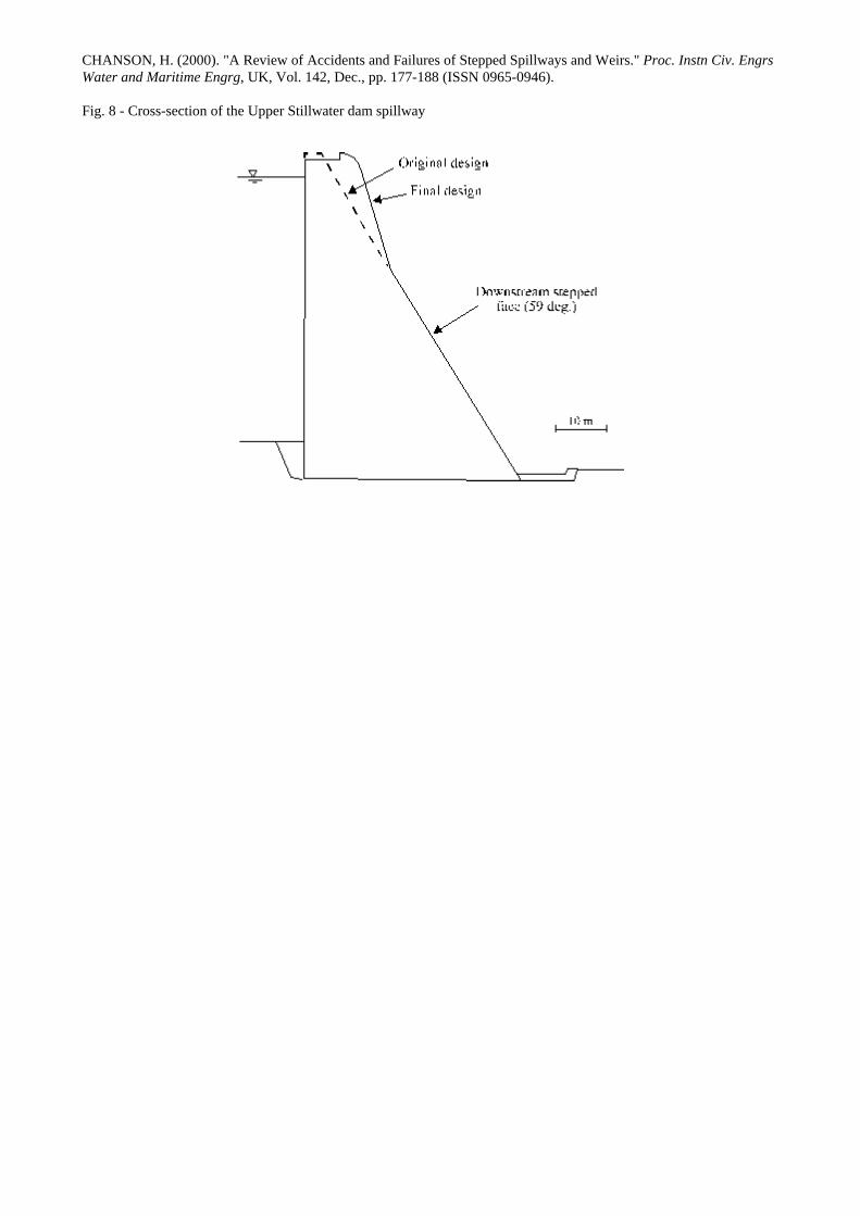
stepped channel hydraulics. The New Victoria dam (Australia), completed in 1991, is a 72-m high RCC dam equipped
with a stepped spillway (Qdes = 702 m3/s, W = 130 m, h = 0.6 m). The spillway design includes an unnecessary break
in slope which has increased the risks of jet deflection at the transition between crest and chute, as at Bucca weir. In
fact the design was duplicated from the Upper Stillwater dam spillway which was supposed to have a 4.57-m wide crest
followed by a straight 59-degree chute (Fig. 8). The final Upper Stillwater design is a 9.14-m wide crest followed by a
72-degree chute and then a 59-degree chute : "The top width was then increased to 30 feet [9.14 m] to facilitate
construction and the slope of the upper portion of the downstream face was increased to 0.32:1 [72º] so that it
intersected the 0.60:1 slope [59º] at elevation 8100.0" (HOUSTON 1987). The crest was widened to allow truck access
and the change in design had no hydrodynamic justification. Errors were made also during recent calculations for the
Gold Creek dam spillway (Australia, 1890). During a hydrological re-assessment of the reservoir, a consultant
calculated a maximum discharge capacity of about 400 m3/s. A recent investigation showed however that overtopping
and associated embankment erosion would occur with spills exceeding 280 m3/s (CHANSON and WHITMORE 1998).
Design engineers must further be reminded that a stepped chute will operate in a nappe flow regime at low to medium
flows although it is designed for a skimming flow regime at maximum flow capacity. "The main hydraulic features of
stepped channel flows are the two different flow regimes"; in each regime, "the step faces are subjected to mean
pressures and pressure fluctuations quite different" (CHANSON 1995, p. 206 & 197 respectively). The spillway and
stilling basin must operate safely and efficiently for a wide range of flow rates. Physical modelling may be used during
design stages to optimise the structure and to ensure a safe operation. Note that, at Lahontan, laboratory tests were
performed only afterwards to assess the causes of failure.
The above mistakes and past accidents suggest however that the design and operation of stepped chute could be better
addressed by some professionals.
CONCLUSION
The study reviews over 20 accidents and failures involving stepped spillway structures. Some failures derived from
basic design errors but others are related to problems specific to stepped chutes. Although the paper does not provide
explicit guidelines for stepped spillway design, the study highlights three types of failures that are specific to stepped
chutes. These are flow instabilities associated with the transition between nappe and skimming flow, the lack
maintenance and low quality of construction.

CHANSON, H. (2000). "A Review of Accidents and Failures of Stepped Spillways and Weirs." Proc. Instn Civ. Engrs Water and Maritime Engrg, UK, Vol. 142, Dec., pp. 177-188 (ISSN 0965-0946).
Transition between nappe and skimming flow must be avoided. It is characterised by hydrodynamic instabilities
causing additional fluctuating loads on the structures, and the resulting fatigue might increase the rate of failure. Figure
2 illustrates that the transition regime is related to the flow rate (or critical depth), step height and chute slope. It further
provides some indication of the range of flow conditions for which transitory flows might occur.
In comparison with smooth chutes, stepped spillways require higher standards of construction. The steps are subjected
to greater hydrodynamic loads than a smooth invert. Regular maintenance of the chute is also essential because damage
to the steps might occur more often than on conventional smooth chutes.
Lessons may be learned from both successful designs and failures. The writer hopes that further experience of stepped
spillway operation could be shared. He includes a questionnaire (Appendix I) and he proposes to gather together any
additional relevant case study.
ACKNOWLEDGMENTS
The author wish to thank the following people for their assistance and help : Professor C.J. APELT, The University of
Queensland, Mr P. BURGI, US Bureau of Reclamation, Ms CHOU Y.H., Brisbane, Mr D. JEFFERY, Goulburn-
Murray Water, Mr J. MITCHELL, Brisbane, Mr R. NILSSON, Brisbane, Mr R. WHEELER, QLD Department of
Natural Resources, Mr A. WICKHAM, Brisbane, Dr Y. YASUDA, Nihon University (Japan).
REFERENCES
BEITZ, E., and LAWLESS, M. (1992). "Hydraulic Model Study for dam on GHFL 3791 Isaac River at Burton Gorge."
Water Resources Commission Report, Ref. No. REP/24.1, Sept., Brisbane, Australia.
BREZNIK, M. (1984). "The Safety and Endurance of the Old Dams of Idrija." Proc. Intl Conf. on Safety of Dams,
Portugal, Balkema Publ., Rotterdam, The Netherlands, pp. 133-139.
BUCKLEY, R.B. (1905). "The Irrigation Works in India." E.&F.N. Spon, London, UK, 2nd ed., 336 pages.
CHANSON, H. (1994). "Hydraulics of Nappe Flow Regime above Stepped Chutes and Spillways." Aust. Civil Engrg
Trans., I.E.Aust., Vol. CE36, No. 1, Jan., pp. 69-76.
CHANSON, H. (1995). "Hydraulic Design of Stepped Cascades, Channels, Weirs and Spillways." Pergamon, Oxford,
UK, Jan., 292 pages.
CHANSON, H. (1996). "Prediction of the Transition Nappe/Skimming Flow on a Stepped Channel." Jl of Hyd. Res.,
IAHR, Vol. 34, No. 3, pp. 421-429.
CHANSON, H. (1997). "A Short History of Stepped Cascades in Australia." ANCOLD Bulletin, No. 106, Aug., pp.
101-111.
CHANSON, H., and WHITMORE, R.L. (1998). "Gold Creek Dam and its Unusual Waste Waterway (1890-1997) :
Design, Operation, Maintenance." Can. Jl of Civil Eng., Vol. 25, No. 4, Aug., pp. 755-768 & Front Cover.
DOUMA, J.H., and GOODPASTURE, R.A. (1940). "Hydraulic Model Studies for Reconstruction of the Lahontan
Dam Spillway." Hydraulic Laboratory Report No. HYD-71, US Bureau of Reclamation, Dept. of the Interior,
Denver, 13 Jan., 2 pages & 8 figures.
ELVIRO, V., and MATEOS, C. (1995). "Spanish Research into Stepped Spillways." Intl Jl Hydropower & Dams, Vol.
2, No. 5, pp. 61-65.

CHANSON, H. (2000). "A Review of Accidents and Failures of Stepped Spillways and Weirs." Proc. Instn Civ. Engrs Water and Maritime Engrg, UK, Vol. 142, Dec., pp. 177-188 (ISSN 0965-0946).
ESSERY, I.T.S., and HORNER, M.W. (1978). "The Hydraulic Design of Stepped Spillways." CIRIA Report No. 33,
2nd edition, Jan., London, UK.
GORDIENKO, P.I. (1944). "Rockfill Overflow Dams." Gidrotekhnicheskoe Stroitel'stvo, No. 3 (in Russian).
GORDIENKO, P.I. (1978). "Reinforced-Concrete-Earth Overflow Dams." Dams & Spillways, Collection of Works No.
61, Issue 2, MISI, Moscow, pp. 3-17 (in Russian).
GOUBET, A. (1992). "Evacuateurs de Crues en Marches d'Escalier." ('Stepped Spillways.') Jl La Houille Blanche, No.
2/3, pp. 159-162. Discussion : No. 2/3, pp. 247-248 (in French).
HADDAD, A.A. (1998). "Water Flow Over Stepped Spillway." Masters Thesis, Polytechnic of Bari, Italy.
HANSEN, K.D., and McLEAN, G.G. (1995). "Roller Compacted Concrete for Overtopping Protection : an Overview."
Proc. 1st Intl Conf. on Water Resources Eng., ASCE, San Antonio TX, USA, Vol. 2, pp. 1016-1020.
HE, G., and ZENG, X. (1995). "The Integral RCC Dam Design Characteristics and Optimization Design of its Energy
Dissipator in Shuidong Hydropower Station." Proc. Intl Symp on RCC Dams, Santander, Spain, IECA-CNEGP,
Vol. 1, pp. 405-412.
HORNER, M.W. (1969). "An Analysis of Flow on Cascades of Steps." Ph.D. thesis, Univ. of Birmingham, UK, May,
357 pages.
HOUSTON, K.L. (1987). "Hydraulic Model Studies of Upper Stillwater Dam Stepped Spillway and Outlet Works."
Report No. REC-ERC-87-6, US Bureau of Reclamation, Denver CO, USA.
HUMBER, W. (1876). "Comprehensive Treatise on the Water Supply of Cities and Towns with Numerous
Specifications of Existing Waterworks." Crosby Lockwood, London, UK.
JANSEN, R.B. (1983). "Dams and Public Safety." US Govt. Printing Office, US Bureau of Reclamation, Denver, USA,
332 pages.
KELLS, J.A. (1995). "Comparison of Energy Dissipation between Nappe and Skimming Flow Regimes on Stepped
Chutes - Discussion." Jl of Hyd. Res., IAHR, Vol. 33, No. 1, pp. 128-133.
MARSH, F.B. (1957). "Danger of Fixed Flashboards shown by Flood at Croton Dam." Civil Engineering, ASCE, Vol.
64, pp. 408-409.
MONTES, J.S. (1994). Private Communication.
NOETZLI, F.A. (1931). "High Dams - A Symposium - Discussion." Transactions, ASCE, Vol. 95, pp. 171-174.
OHTSU, I.O., and YASUDA, Y. (1997). "Characteristics of Flow Conditions on Stepped Channels." Proc. 27th IAHR
Biennal Congress, San Francisco, USA, Theme D, pp. 583-588.
PEYRAS, L., ROYET, P., and DEGOUTTE, G. (1992). "Flow and Energy Dissipation over Stepped Gabion Weirs." Jl
of Hyd. Engrg., ASCE, Vol. 118, No. 5, pp. 707-717.
PRAVDIVETS, Y.P. (1992). "Stepped Spillways in World and Domestic Hydraulic Engineering." Gidrotekhnicheskoe
Stroitel'stvo, No. 10, Oct., pp. 28-32 (in Russian). (Translated in Hydrotechnical Construction, 1993, Vol. 27, No.
10, Plenum Publ., pp. 589-594).
RAJARATNAM, N. (1990). "Skimming Flow in Stepped Spillways." Jl of Hyd. Engrg., ASCE, Vol. 116, No. 4, pp.
587-591. Discussion : Vol. 118, No. 1, pp. 111-114.
RU, S.X., TANG, C.Y., PAN, R.W., and HE, X.M. (1994). "Stepped Dissipator on Spillway Face." Proc. 9th APD-
IAHR Congress, Singapore, Vol. 2, pp. 193-200.
SANKEY, R.H. (1867)."Irrigation in Mysore." Professional Papers on Indian Engineering, Vol. IV, No. CL, p. 212.
SCHOKLITSCH, A. (1937). "Hydraulic Structures." ASME, New York, USA, 2 Volumes.

CHANSON, H. (2000). "A Review of Accidents and Failures of Stepped Spillways and Weirs." Proc. Instn Civ. Engrs Water and Maritime Engrg, UK, Vol. 142, Dec., pp. 177-188 (ISSN 0965-0946).
SCHUYLER, J.D. (1909). "Reservoirs for Irrigation, Water-Power and Domestic Water Supply." John Wiley & sons,
2nd edition, New York, USA.
STEPHENSON, D. (1988). "Stepped Energy Dissipators." Proc. Intl Symp. on Hydraulics for High Dams, IAHR,
Beijing, China, pp. 1228-12-35.
WEGMANN, E. (1907). "The Design of the New Croton Dam." Transactions, ASCE, Vol. LXVIII, No. 1047, pp. 398-
457.
WEGMANN, E. (1922). "The Design and Construction of Dams." John Wiley & Sons, New York, USA, 7th edition.
WILEY, A.J. (1931). "High Dams - A Symposium - Closure." Transactions, ASCE, Vol. 95, pp. 212-217.
APPENDIX I - QUESTIONNAIRE
Please address any relevant information to the writer :
Dr H. CHANSON, Dept. of Civil Engineering, The University of Queensland, Brisbane QLD 4072, Australia
Fax.: (61 7) 33 65 45 99 Email: [email protected]
Project name :
Reservoir
Name :
Catchment area (km2) :
Capacity (m3) :
Purpose :
Dam
Name :
Type :
Construction material :
Dam height/length (m/m) :
Further details :
Spillway
Name (if different) :
Probable Maximum Flood
(m3/s):
Design discharge (m3/s) :
Type :
Intake details :
width, type

CHANSON, H. (2000). "A Review of Accidents and Failures of Stepped Spillways and Weirs." Proc. Instn Civ. Engrs Water and Maritime Engrg, UK, Vol. 142, Dec., pp. 177-188 (ISSN 0965-0946).
Chute details :
width, slope, step height
Energy dissipator :
type, widht, length
Failure/Accident
Date :
Flow rate (m3/s):
maximum, duration
Rainfall/hydrological event :
Accident/failures :
Other information :
Please forward the information to the writer :
Dr H. CHANSON, Dept. of Civil Engineering, The University of Queensland, Brisbane QLD 4072, Australia
Fax.: (61 7) 33 65 45 99 Email: [email protected]
List of tables
Table 1 - Summary of accidents, incidents and failures (sort by year of accident)
Table 2 - Characteristics of unlined rock stepped cascades
Table 3 - Analysis of accident and failure cases

CHANSON, H. (2000). "A Review of Accidents and Failures of Stepped Spillways and Weirs." Proc. Instn Civ. Engrs Water and Maritime Engrg, UK, Vol. 142, Dec., pp. 177-188 (ISSN 0965-0946).
Table 1 - Summary of accidents, incidents and failures (sorted by year of accident)
Dam/Reservoir Year of accident
Years of construct.
Accident/Failure Construction details
Lives lost
(1) (2) (3) (4) (5) Puentes dam, Spain 1802 1785-1791 Dam break caused by a foundation failure.
Gravity dam with overflow spillway : Hdam = 50 m. 608
Sreeramadavara weir, India
1842, 1844, 1859,
1860, 1863
-- Failures. Rubble masonry weir : h = 0.348 m, l = 0.762 m, θ = 21.8 deg.
--
Muddoor weir, India 1850s -- Failure. Masonry weir : Hdam ~ 4.4 m, h ~ 0.4, l ~ 0.3 m.
--
Narora weir, India 1898 1877 Failure of stilling basin during very-large overflow (qw = 11.9 m2/s).Drop structure : Hdam = 3.05 m, W = 1,160 m, qdes = 2.93 m2/s.
--
Minneapolis Mill dam, USA
1899 1893-1894 Dam break during a small spill (qw = 0.04 m2/s) caused by cracks resulting from ice pressure on the dam. Gravity dam with overflow spillway : Hdam = 5.5 m, W = 51.8 m, 9 steps, h = 0.61 m.
--
Arizona Canal dam 1891 and 1905
1887 Partial destruction of the dam during a flood (qw = 11.3 m2/s) caused by foundation problems and timber deterioration. Timber crib dam : Hdam = 10 m, W ≈ 245 m, 3 steps, qdes ≈ 33 m2/s.
--
Warren dam, Australia
1917 1916 Dam overtopped (Qw = 128 m3/s) without damage. Concrete gravity dam :Hdam = 17.4 m, 4 steps, h = 0.37 m, Qdes ≈ 100 m3/s.
None
St. Francis dam, USA 1928 1926 Dam break caused by foundation failure. Arched gravity dam : Hdam = 62.5 m, h = 0.4 m.
450
Lahontan dam, USA 1930s 1915 Damaged spillway concrete caused by freezing and thawing, and hydraulic scour. Earthfill dam with concrete spillway : Hdam = 49 m, Qdes = 850 m3/s. Right stepped spillway : h = 3.35 m, W = 45.7 m. Left stepped spillway : h = 3.05 m, W = 76.3 m & 45.7 m.
None
Kobila dam, Slovenia 1948 1586 Dam destruction during a flood caused by lack of maintenance. Timber crib dam : Hdam = 10 m.
--
New Croton dam, USA
1955 1892-1905 Spillway damage during flood releases (Qw ≈ 651 m3/s) Masonry gravity dam : Hdam = 90.5 m, W ≈ 305 m, h = 2.1 m, Qdes ≈ 1,550 m3/s.
None
Bonshaw weir, Australia
1956 1952-1953 Weir failure resulting abutment bypass and failure during major flood overflow. Timber crib piled weir : Hdam = 3.7 m, 4 steps, h = 0.9 m, Qdes = 1,560 m3/s.
None
Goulburn weir, Australia
1978 1891 1- Gate failure caused by corrosion and 2- foundation stability problem. Concrete gravity dam : Hdam = 15 m, W = 126 m, h = 0.5 m, Qdes = 1,980 m3/s.
None
Moscovite earth dams, Russia (former USSR)
1978-80 1978 Failure of two overflow earth dams caused by incorrect drainage layer construction. Earthfill embankments with overflow stepped spillway made of pre-cast concrete blocks : Hdam = 7 to 15 m, Qdes ≈ 30 to 60 m3/s.
--
Binda weir, Australia 1986 1950-1953 Weir destroyed (blown) because unsafe (lack of maintenance). Timber crib piled weir : Hdam = 5.2 m, 5 steps.
None
Silverleaf weir, Australia
1995 1951-1953 Weir overtopping during refurbishment works (no damage). Timber crib piled weir : Hdam = 5 m, 4 steps.
None

CHANSON, H. (2000). "A Review of Accidents and Failures of Stepped Spillways and Weirs." Proc. Instn Civ. Engrs Water and Maritime Engrg, UK, Vol. 142, Dec., pp. 177-188 (ISSN 0965-0946).
Dam/Reservoir Year of accident
Years of construct.
Accident/Failure Construction details
Lives lost
(1) (2) (3) (4) (5) Dartmouth dam, Australia
1996 1977 Unlined rock steps damaged by flow concentration during low spill (Qw ≈ 225 m3/s). Earth/rockfill embankment with unlined rock cascade spillway : Hdam = 180 m, W = 91.4 (concrete crest) & 300 to 350 m (cascade), h = 15 m, Qdes = 2,755 m3/s.
None
Bucca weir, Australia 1987 1986-1987 Nappe deflection at first step associated with loud noise and vibrations at low overflows. RCC overflow stepped weir : Hdam = 11.8 m, W = 131 m, h = 0.6 m, Qdes = 7,250 m3/s.
None
Debris dams, Taiwan 1994 1994 Ill-designed debris control system. Three concrete debris dam.
None
Hilliard Creek weir, Australia
1990s 1948 Ruins (lack of maintenance). Timber crib piled weir : Hdam = 3.4 m.
None
Notes : (--) unknown information. References : BREZNIK (1984), BUCKLEY (1905), CHANSON (1995), DOUMA
and GOODPASTURE (1940), PRAVDIVETS (1992), Present study.
Table 2 - Characteristics of unlined rock stepped cascades
Name Year Qdes W h Comments m3/s m m
(1) (2) (3) (4) (5) (6) Ternay, France 1868 -- -- 0.3 to 0.8 Still in use. Dam height : 41 m. La Tâche, France 1891 -- 2.2 2.4 to 5.4 Still in use. Dam height : 51 m. Junction Reefs, Australia 1897 37.9 20 2 to 4 Still in use. Dam height : 19 m. Reservoir
fully-silted. Bellfield, Australia 1966 20.9 23 12.2 Dam height : 55 m. Dartmouth, Australia 1977 2,755 300 to 350 15 Dam height : 180 m. La Grande 2, Canada 1982 16,140 122 9.1 to 17.8 Dam height : 134 m.
Note : (--) data not available.
Table 3 - Analysis of accident and failure cases
Mode of failure Description Spillway/weir (1) (2) (3)
Design errors Improper hydrological assessment Narora, Warren, Debris dams in Taiwan
Foundation failure and stability problem
Puentes, St Francis, Bonshaw, Goulburn
Problems specific to stepped chutes
Flow instabilities associated with transitory regime nappe/skimming flow
Arizona canal, Lahontan, New Croton
Maintenance (lack of) Kobila, Arizona canal, Hilliard Creek, Binda
Quality of construction New Croton, St Francis (cracks) Lahontan (concrete) Bonshaw (timber) Moscovite earth dams
CHANSON, H. (2000). "A Review of Accidents and Failures of Stepped Spillways and Weirs." Proc. Instn Civ. Engrs Water and Maritime Engrg, UK, Vol. 142, Dec., pp. 177-188 (ISSN 0965-0946).
List of captions
Fig. 1 - Sketch of nappe and skimming flows on stepped chutes
Fig. 2 - Onset of skimming flow : comparison between Equation (1), CHANSON's (1994) correlation and model data
(BEITZ and LAWLESS 1992, ELVIRO and MATEOS 1995, ESSERY and HORNER 1978, HADDAD 1998,
HORNER 1969, KELLS 1994, MONTES 1994, OHTSU and YASUDA 1997, PEYRAS et al. 1992, RU et al. 1994,
STEPHENSON 1988)
Fig. 3 - New Croton dam spillway around 1910 (Courtesy of the American Society of Civil Engineers)
The spillway was heavily damaged in 1955 during flood release (650 m3/s) less than the design capacity (1550 m3/s)
Fig. 4 - Bonshaw weir
(A) First Bonshaw weir around 1953, view from downstream (Courtesy of the Department of Natural Resources)
(B) Small overflow on 19 April 1955 (Courtesy of the Department of Natural Resources)
(C) View from the present weir from the left bank : note the ruins of the first weir in the foreground, downstream of the
sheet-pile cascade (Photograph taken in February 1998)
Fig. 5 - Bucca weir spillway : low overflow (cross-section)
Fig. 6 - Dartmouth dam spillway during the 1996 overflow (Qw ~ 225 m3/s) (Courtesy of Mr JEFFERY, Goulburn-
Murray Water)
(A) Spillway view from downstream : note the flow concentration in the middle of the photograph and the absence of
flow on the right edge of the photograph
(B) Details of the cascading flow from the left bank, showing the concrete-lined chute and the first steps
Fig. 7 - Silverleaf weir
(A) During construction in April 1952 (Courtesy of QLD Department of Natural Resources)
(B) view from downstream right bank during a low overflow, shortly after completion (Courtesy of Mr J. MITCHELL)
(C) Refurbished weir viewed from left bank : the upstream concrete wall is clearly visible (Photograph taken in
November 1997)
Fig. 8 - Cross-section of the Upper Stillwater dam spillway
CHANSON, H. (2000). "A Review of Accidents and Failures of Stepped Spillways and Weirs." Proc. Instn Civ. Engrs Water and Maritime Engrg, UK, Vol. 142, Dec., pp. 177-188 (ISSN 0965-0946).
Fig. 1 - Sketch of nappe and skimming flows on stepped chutes
CHANSON, H. (2000). "A Review of Accidents and Failures of Stepped Spillways and Weirs." Proc. Instn Civ. Engrs Water and Maritime Engrg, UK, Vol. 142, Dec., pp. 177-188 (ISSN 0965-0946).
Fig. 2 - Onset of skimming flow : comparison between Equation (1), CHANSON's (1994) correlation and model data
(BEITZ and LAWLESS 1992, ELVIRO and MATEOS 1995, ESSERY and HORNER 1978, HADDAD 1998,
HORNER 1969, KELLS 1994, MONTES 1994, OHTSU and YASUDA 1997, PEYRAS et al. 1992, RU et al. 1994,
STEPHENSON 1988)
CHANSON, H. (2000). "A Review of Accidents and Failures of Stepped Spillways and Weirs." Proc. Instn Civ. Engrs Water and Maritime Engrg, UK, Vol. 142, Dec., pp. 177-188 (ISSN 0965-0946).
Fig. 3 - New Croton dam spillway (Courtesy of Matthew HILLER) - Recent photograph during a small overflow
Fig. 4 - Bonshaw weir
(A) First Bonshaw weir around 1953, view from downstream (Courtesy of the Department of Natural Resources)
CHANSON, H. (2000). "A Review of Accidents and Failures of Stepped Spillways and Weirs." Proc. Instn Civ. Engrs Water and Maritime Engrg, UK, Vol. 142, Dec., pp. 177-188 (ISSN 0965-0946).
Fig. 4 - Bonshaw weir
(B) Small overflow on 19 April 1955 (Courtesy of the Department of Natural Resources)
(C) View from the present weir from the left bank : note the ruins of the first weir in the foreground, downstream of the
sheet-pile cascade (Photograph taken in February 1998)
CHANSON, H. (2000). "A Review of Accidents and Failures of Stepped Spillways and Weirs." Proc. Instn Civ. Engrs Water and Maritime Engrg, UK, Vol. 142, Dec., pp. 177-188 (ISSN 0965-0946).
Fig. 5 - Bucca weir spillway : low overflow (cross-section)
Fig. 6 - Dartmouth dam spillway during the 1996 overflow (Qw ~ 225 m3/s) (Courtesy of Mr JEFFERY, Goulburn-
Murray Water)
(A) Spillway view from downstream : note the flow concentration in the middle of the photograph and the absence of
flow on the right edge of the photograph
CHANSON, H. (2000). "A Review of Accidents and Failures of Stepped Spillways and Weirs." Proc. Instn Civ. Engrs Water and Maritime Engrg, UK, Vol. 142, Dec., pp. 177-188 (ISSN 0965-0946).
Fig. 6 - Dartmouth dam spillway during the 1996 overflow (Qw ~ 225 m3/s) (Courtesy of Mr JEFFERY, Goulburn-
Murray Water) (B) Details of the cascading flow from the left bank, showing the concrete-lined chute and the first steps
Fig. 7 - Silverleaf weir
(A) During construction in April 1952 (Courtesy of QLD Department of Natural Resources)
CHANSON, H. (2000). "A Review of Accidents and Failures of Stepped Spillways and Weirs." Proc. Instn Civ. Engrs Water and Maritime Engrg, UK, Vol. 142, Dec., pp. 177-188 (ISSN 0965-0946).
Fig. 7 - Silverleaf weir
(B) view from downstream right bank during a low overflow, shortly after completion (Courtesy of Mr J. MITCHELL)
(C) Refurbished weir viewed from left bank : the upstream concrete wall is clearly visible (Photograph taken in
November 1997)
CHANSON, H. (2000). "A Review of Accidents and Failures of Stepped Spillways and Weirs." Proc. Instn Civ. Engrs Water and Maritime Engrg, UK, Vol. 142, Dec., pp. 177-188 (ISSN 0965-0946).
Fig. 8 - Cross-section of the Upper Stillwater dam spillway