Embed Size (px)
Citation preview

D-M
-E E
uro
pe
29/0
6/20
16
Standardized System for Molding Internal Threads• Metric-rack design• Off -the-shelf replacement parts• Simplifiesmolddesign• Applicable to different design styles• Technical and application support• Rack sized to provide maximum stroke lengths
Hydraulic Unscrewing Device
ATP: 0800 301 060F: 0800 401 [email protected]
BEP:+32(0)15288730F:+32(0)[email protected]
CHP: +41 0848 567 364F: +41 0848 567 [email protected]
CZP: 800 142 451 | +420 572 151 754F: 800 142 450 | +420 571 611 [email protected]
DEP:08006648250|+49(0)23514370F:08006648251|+49(0)[email protected]
ESP: 900 900 342F: 900 900 [email protected]
FRP: +33 1 49 93 92 23F: +33 1 49 93 92 [email protected]
HUP: 06 80 205003F: +32 15 40 51 [email protected]
ITP: 800 089 734F: 800 089 [email protected]
NLP:+31(0)206545571F:+31(0)[email protected]
PLP: +800 331 1312 | +32 15 21 50 92F: +800 331 1313 | +32 15 40 51 [email protected]
PTP: 800 207 900F: 800 207 [email protected]
SKP: 0800 142 451 | +420 572 151 754F: 0800 142 450 | +420 571 611 [email protected]
UKP: +44 2071 3300 37F: +44 2071 3300 [email protected]
Other CountriesP: +32 15 28 87 30F: +32 15 40 51 [email protected]
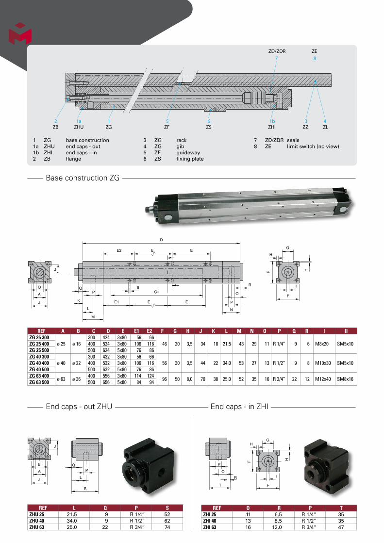
2 1a 1 5 6 1b 3 4
7 8
ZB ZHU ZG ZF ZS ZHI ZZ ZL
ZD/ZDR ZE
1 ZG base construction1a ZHU end caps - out1b ZHI end caps - in2 ZB flange
3 ZG rack4 ZG gib5 ZF guideway6 ZS fixing plate
7 ZD/ZDR seals8 ZE limit switch (no view)
Base construction ZG
End caps - out ZHU End caps - in ZHI
B
A
J
J
Q
K
L
P
M
C=II
E2 E
D
E1 E
R
P
O
N
I
F
H
G
HF
E
E
REF A B C D E E1 E2 F G H J K L M N O P Q R I IIZG 25 300
ø 25 ø 16300 424 3x80 56 66
46 20 3,5 34 18 21,5 43 29 11 R 1/4” 9 6 M8x20 SM5x10ZG 25 400 400 524 3x80 106 116ZG 25 500 500 624 5x80 76 86ZG 40 300
ø 40 ø 22300 432 3x80 56 66
56 30 3,5 44 22 34,0 53 27 13 R 1/2” 9 8 M10x30 SM5x10ZG 40 400 400 532 3x80 106 116ZG 40 500 500 632 5x80 76 86ZG 63 400
ø 63 ø 36400 556 3x80 114 124
96 50 8,0 70 38 25,0 52 35 16 R 3/4” 22 12 M12x40 SM8x16ZG 63 500 500 656 5x80 84 94
REF L Q P SZHU 25 21,5 9 R 1/4” 52ZHU 40 34,0 9 R 1/2” 62ZHU 63 25,0 22 R 3/4” 74
REF O R P TZHI 25 11 6,5 R 1/4” 35ZHI 40 13 8,5 R 1/2” 35ZHI 63 16 12,0 R 3/4” 47
J
A
B
J
Q
L
P
S
P
O
R
T F
H
H
F
I
G

Flanges ZB
Racks ZZ
Gibs ZL
Guideways ZF
Z
F
X
L L
X
L
XX
L
Y
X
L
L
X
Y
I*
Version 1 Version 2 Version 3* I is the thread dimension
Q
G
S
F/2 X
V
H
T
- I
for I R Modulus
* Pitch line of rack to center of hydraulic cylinder
*
Q
S
HT
G
V
X
F/2
- I *
* Distance to center of hydraulic cylinder
TE E3EE EE3
S
J
F II
REF A X Y F Z L I: forZB 25-1
ø 25 27 12,5 46 20 10,52 x M8 x 20
ZB 25-2 3 x M8 x 20ZB 25-3 4 x M8 x 20ZB 40-1
ø 40 34 20,0 56 30 11,02 x M10 x 30
ZB 40-2 3 x M10 x 30ZB 40-3 4 x M10 x 30ZB 63-1
ø 63 55 30,0 96 40 15,01 x M12 x 40 + 1 M16 x 45
ZB 63-2 2 x M12 x 40 + 1 M16 x 45ZB 63-3 3 x M12 x 40 + 1 M16 x 45
REF A F/2 G H Q Modules S T V X IZZ 25-600/1,0
ø 25 23 20 3,4
6001,00
13 5 36,2 27 M8 x 20ZZ 25-800/1,0 800ZZ 25-600/1,25 600
1,25ZZ 25-800/1,25 800ZZ 40-600/1,5
ø 40 28 30 3,4600
1,50 23 5 43,0 34M10 x 30ZZ 40-800/1,5 800
ZZ 63-800/2,0ø 63 48 50 7,9
8002,00 40 7 68,0 55
M12 x 40ZZ 63-900/2,0 900
REF A F/2 G H Q S T V X IZL 25-800 ø 25 23 20 3,35 800 13 5 49,5 27 M8 x 20ZL 40-800 ø 40 28 30 3,50 800 23 5 64,5 34 M10 x 30ZL 63-900 ø 63 48 50 8,00 900 40 7 100,0 55 M12 x 40
REF A C E E3 F J S T IIZF 25-300
ø 25300 3x80 46
46 34 14 4 SM 5x10ZF 25-400 400 3x80 96ZF 25-500 500 5x80 66ZF 40-300
ø 40300 3x80 46
56 44 24 4 SM 5x10ZF 40-400 400 3x80 96ZF 40-500 500 5x80 66ZF 63-400
ø 63400 3x80 104
96 70 42 6 SM 8x16ZF 63-500 500 5x80 74
Note: Two guideways are required per Rack or per Gib.

Limit switch ZE
Calculation example
Fixing plates ZS Seals (kit) ZD Kit: Seals ZD + Mounting tools ZDR
a
M6
G
b
REF A G a bZS 25 ø 25 20 40 6ZS 40 ø 40 30 50 6ZS 63 ø 63 50 80 15
REFZD 25ZD 40ZD 63
REFZDR 0025ZDR 0040ZDR 0063
~56
12
7
22
8
12
28Ca. 60
8.5
27
62
Included
for SM 4 x 20
Incl.: 2 SM 4 x 20 1 DP 3 x 16 1 GS 4 x 20 1 M4 Din 934
7
_3
16 22
M4
4
8
SM 4 x 20
Stroke
Installation details for Limit Switch ZE-25/40
For gear information please contact D-M-EREF
ZE 25/40
A. Strokea. Requiredrevolutions(threadAcore) = thread height + safety threadlead (min0,5t)
= 12 mm + 0,5 rev. = 4,5 rev. 3 mm
b. 1. Requiredstroke(mm) = pitch circle x p x rev. = 30 mm x 3,14 x 4,5 rev. = 424 mm If required stroke is too
long, a cog wheel transmission gear should be used
2. Length of rack: b2 = X + Y + b1
c. Stripperstroke(mm) = cylinder stroke - required rack
stroke = 500 mm - 424 mm = 76 mm{
b2
Attached to mold
Stationary hydraulic cylinder
Moving rack
required stroke to unscrew capsX Unusable
space
Y Max. productdistancepitch circle
-Pitch dia. x πSpur gear
b1 > π D x rev.

Calculation example
Calculation example
B. Control Cam calculationd. Movingcam(∞) tan α = lead dia.pitchcirclexπ tan α = 3 mm = 0,031847 30 mm x 3,14 α = 1°49’26”
e. Strippercam(ß) tan ß = Stripper height Stripper stroke tan ß = 4 mm = 0,0526315 76 mm ß = 3°00’46”
12
3
M20
Ø 30B
A
4
76424
500
ß3°00'46"α
1°49'26"
Full Open PositionAnti-Rotational Stripper Plate “or Bump” moves up at faster rate due to angle ß and separates from the Main Stripper Plate moving at rate due to angle α
Closed PositionBoth stripper plates move up together at the same rate due to angle α
Anti-rotational stripper plate
Main stripper plate
Moving hydraulic cylinder pushes gib and rack
Stationary hydraulic cylinder body
Moves main stripper plate
Bump
Bump lift
Stroke
O.D. of threads (Major Thread dia. of the core)
Thre
ad h
eigh
t
Thre
ad le
ad
Anti-rotational stripper plate
Main stripperplate
Stripper plates pushed up by gib angle
Threads get rotated
Spur gear
pitch dia.
Rack
Gib
closed
open
C. Unscrewing force*f. Residualpressure(bar) 1/100 of max. injection pressure = 1000bar ≈10bar≈1N/mm2 100
g. Effectivecoresurfacearea(mm2) = thread dia. x p x thread height x 2* = 20 mm x 3,14 x 12 mm x 2 = * 1507 mm2 * - 2 x height for developped surface
( ) * - frontal area is neglected
h. Unscrewingtorque(Nmm) = Holding pressure x surface x thread = radius =1N/mm2x1507mm2x10mm=
15070Nmm
i. Unscrewingforcerack(kN) = unscrewing torque x number of cores radius pitch circle = 15070Nmmx4=4019N=4,02kN 15 mm
k. Hydraulicforce(kN) = Unscrewing force x 1,5 =4,02kNx1,5=6,03kN
(50%safety,hencex1,5)
kN kN
barbar
Workingstroke Return Back
*These figures should only be used as a guideline as many other factors will affect the calculation. (Material, variation of dimensions, material shrinkage, core surface area, temperature, lubricant, etc...)
80 100 120 140 150 bar A3,9 4,9 5,9 6,8 7,4
kNø 25
10,0 12,5 15,1 17,6 18,7 ø 4024,9 31,1 37,4 43,6 46,6 ø 63
B bar 80 100 120 140 150ø 16
kN2,3 2,9 3,5 4,1 4,4
ø 22 7,0 8,8 10,5 12,2 13,2ø 36 16,8 21,0 25,2 29,3 31,5
Dimensions only valid for above mentioned example.
D-M
-E E
uro
pe
29/0
6/20
16
DME Europe C.V.B.A. Schalienhoevedreef 20D, B-2800 Mechelen , Belgium - Trade Register Mechelen, VAT BE 0456.932.455Prices in EURO per piece. Subject to change without prior notice. For conditions of sales and price info see www.dme.net.
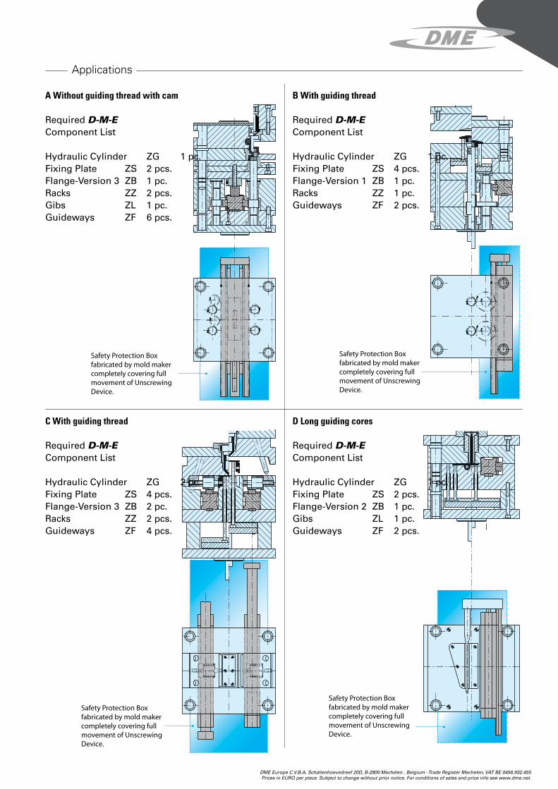
Applications
Safety Protection Box fabricated by mold maker completely covering full movement of Unscrewing Device.
Safety Protection Box fabricated by mold maker completely covering full movement of Unscrewing Device.
Safety Protection Box fabricated by mold maker completely covering full movement of Unscrewing Device.
Safety Protection Box fabricated by mold maker completely covering full movement of Unscrewing Device.
A Without guiding thread with cam
Required D-M-E Component List
Hydraulic Cylinder ZG 1 pc.Fixing Plate ZS 2 pcs.Flange-Version 3 ZB 1 pc.Racks ZZ 2 pcs. Gibs ZL 1 pc.Guideways ZF 6 pcs.
C With guiding thread
Required D-M-E Component List
Hydraulic Cylinder ZG 2 pc.Fixing Plate ZS 4 pcs.Flange-Version 3 ZB 2 pc.Racks ZZ 2 pcs. Guideways ZF 4 pcs.
B With guiding thread
Required D-M-E Component List
Hydraulic Cylinder ZG 1 pc.Fixing Plate ZS 4 pcs.Flange-Version 1 ZB 1 pc.Racks ZZ 1 pc. Guideways ZF 2 pcs.
D Long guiding cores
Required D-M-E Component List
Hydraulic Cylinder ZG 1 pc.Fixing Plate ZS 2 pcs.Flange-Version 2 ZB 1 pc.Gibs ZL 1 pc. Guideways ZF 2 pcs.