Embed Size (px)
Citation preview
PL 01 T EE
dit
ion
:0
1/1
0.2
00
3
� Group 1, 2 and 3 with displacements from 0.07 in3/rev (1,07 cm
3/rev) to 5.56 in
3/rev (91.10 cm
3/rev).
� Drive shafts, mounting flanges and ports according to the international standards.
� Combination of multiple pumps in standard version, common inlet and separated stages.
� Integrated outboard bearings for heavy duty application.
� Many types of built-in valves.
DISPLACEMENTS
From 0.07 in3/rev
(1.07 cm3/rev)
To 5.56 in3/rev
(91.10 cm3/rev)
PRESSURE
Max. Continuous 3770 psi
(260 bar)
Max. Intermittent 4060 psi
(280 bar)
Max. Peak 4350 psi
(300 bar)
MAX. SPEED
4000 min-1
Hydraulic gear pumps and motors
through bore aluminum body
*D0009602*
“POLARIS” more than fifty years of Casappa experience in design and production of hydraulic components, characterized by lar-
ge investments in research and development in order to propose new and personalized solutions to the market. Our use of CAD
3D in the developement of this generation permit us the 3D modelling and the virtual simulation of the behaviour of the compo-
nents inserted in the hydraulic circuit. This means that the process will take less time and the quality of the products is better.
Polaris pumps and motors are basically composed of a gear housing in aluminium alloy, two gear wheels supported by sleeve
bearings and two end plates, the front and the rear cover, either in aluminium or in cast iron with excellent mechanical characteri-
stics. Our success is based largely on the quality of our product. This guaranties the consistencies of the efficiencies and low le-
vel of noise emission during the life of our products.
Polaris
2 002 DCAT033-001
Section Page
FEATURES . . . . . . . . . . . . . . . . . . . . . . . . . . . . . . . . . . . . . . . . . . . . . 3
GENERAL DATA PUMPS AND MOTORS . . . . . . . . . . . . . . . . . . . . . . . . . . . . . 5
PUMPS PERFORMANCE CURVES . . . . . . . . . . . . . . . . . . . . . . . . . . . . . . . . . 7
MOTORS PERFORMANCE CURVES . . . . . . . . . . . . . . . . . . . . . . . . . . . . . . . . 19
SINGLE UNITS DIMENSION. . . . . . . . . . . . . . . . . . . . . . . . . . . . . . . . . . . . . 31
MULTIPLE PUMPS. . . . . . . . . . . . . . . . . . . . . . . . . . . . . . . . . . . . . . . . . . 36
MULTIPLE PUMPS DIMENSION . . . . . . . . . . . . . . . . . . . . . . . . . . . . . . . . . . 42
VERSIONS (OUTBOARD BEARINGS FOR SHAFTS) . . . . . . . . . . . . . . . . . . . . . . . 46
DRIVE SHAFTS . . . . . . . . . . . . . . . . . . . . . . . . . . . . . . . . . . . . . . . . . . . 51
MOUNTING FLANGES . . . . . . . . . . . . . . . . . . . . . . . . . . . . . . . . . . . . . . . 57
PORTS . . . . . . . . . . . . . . . . . . . . . . . . . . . . . . . . . . . . . . . . . . . . . . . . 68
CHANGING ROTATION . . . . . . . . . . . . . . . . . . . . . . . . . . . . . . . . . . . . . . . 74
INSTRUCTIONS . . . . . . . . . . . . . . . . . . . . . . . . . . . . . . . . . . . . . . . . . . . 75
VALVES AVAILABILITY . . . . . . . . . . . . . . . . . . . . . . . . . . . . . . . . . . . . . . 76
HOW TO ORDER. . . . . . . . . . . . . . . . . . . . . . . . . . . . . . . . . . . . . . . . . . . 77
INDEX
01
/10
.03
Polaris
DCAT033-002 002 3
FEATURES
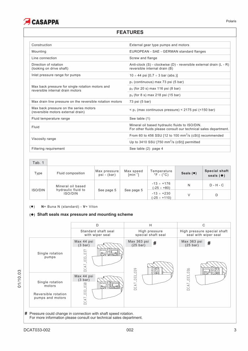
Construction External gear type pumps and motors
Mounting EUROPEAN - SAE - GERMAN standard flanges
Line connection Screw and flange
Direction of rotation(looking on drive shaft)
Anti-clock (S) - clockwise (D) - reversible external drain (L - R)reversible internal drain (B)
Inlet pressure range for pumps 10 � 44 psi [0,7 � 3 bar (abs.)]
Max back pressure for single rotation motors andreversible internal drain motors
p1 (continuous) max 73 psi (5 bar)
p2 (for 20 s) max 116 psi (8 bar)
p3 (for 8 s) max 218 psi (15 bar)
Max drain line pressure on the reversible rotation motors 73 psi (5 bar)
Max back pressure on the series motors(reversible motors external drain)
< p1 (max continuous pressure) < 2175 psi (<150 bar)
Fluid temperature range See table (1)
FluidMineral oil based hydraulic fluids to ISO/DIN.For other fluids please consult our technical sales department.
Viscosity rangeFrom 60 to 456 SSU [12 to 100 mm
2/s (cSt)] recommended
Up to 3410 SSU [750 mm2/s (cSt)] permitted
Filtering requirement See table (2) page 4
01
/10
.03
Tab. 1
Type Fluid compositionMax pressure
psi - (bar)Max speed
[min-1
]Temperature
°F - (°C) Seals (�)Special shaft
seals (�)
ISO/DIN
Mineral oil basedhydraulic fluid to
ISO/DINSee page 5 See page 5
-13 � +176
(-25 � +80)N D - H - C
-13 � +230
(-25 � +110)V D
(�) N= Buna N (standard) - V= Viton
(�) Shaft seals max pressure and mounting scheme
D H C
Standard shaft sealwith wiper seal
High pressurespecial shaft seal
High pressure special shaftseal with wiper seal
Single rotationpumps
# #
Single rotationmotors
Reversible rotationpumps and motors
Max 363 psi(25 bar)
Max 363 psi(25 bar)
Max 44 psi(3 bar)
# Pressure could change in connection with shaft speed rotation.For more information please consult our technical sales department.
Max 44 psi(3 bar)
Polaris
4 002 DCAT033-002
FEATURES
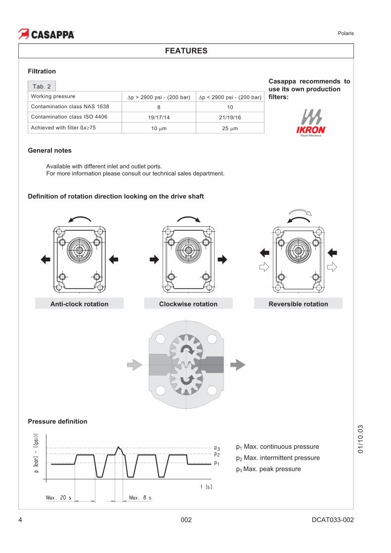
Filtration
Pressure definition
Definition of rotation direction looking on the drive shaft
Clockwise rotation Reversible rotationAnti-clock rotation
Available with different inlet and outlet ports.
For more information please consult our technical sales department.
General notes
Casappa recommends to
use its own production
filters:
Tab. 2
Working pressure �p > 2900 psi - (200 bar) �p < 2900 psi - (200 bar)
Contamination class NAS 1638 8 10
Contamination class ISO 4406 19/17/14 21/19/16
Achieved with filter ßx�75 10 �m 25 �m
01
/10
.03
p1 Max. continuous pressure
p2 Max. intermittent pressure
p3 Max. peak pressure
Polaris
DCAT033-003 002 5
01
/10
.03
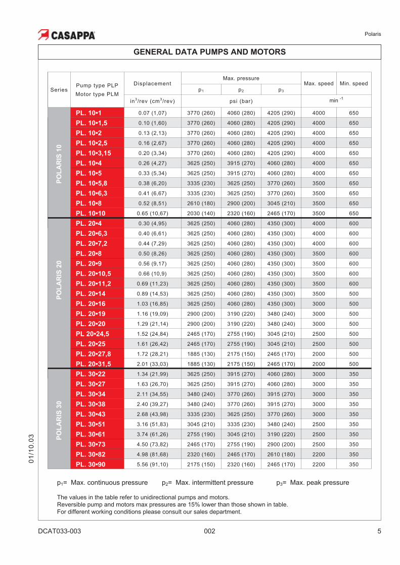
The values in the table refer to unidirectional pumps and motors.
Reversible pump and motors max pressures are 15% lower than those shown in table.
For different working conditions please consult our sales department.
GENERAL DATA PUMPS AND MOTORS
p3= Max. peak pressurep1= Max. continuous pressure p2= Max. intermittent pressure
SeriesPump type PLP
Motor type PLM
DisplacementMax. pressure
Max. speed Min. speedp1 p2 p3
in3/rev (cm
3/rev) psi (bar) min -1
PO
LA
RIS
10
PL. 10•1 0.07 (1,07) 3770 (260) 4060 (280) 4205 (290) 4000 650
PL. 10•1,5 0.10 (1,60) 3770 (260) 4060 (280) 4205 (290) 4000 650
PL. 10•2 0.13 (2,13) 3770 (260) 4060 (280) 4205 (290) 4000 650
PL. 10•2,5 0.16 (2,67) 3770 (260) 4060 (280) 4205 (290) 4000 650
PL. 10•3,15 0.20 (3,34) 3770 (260) 4060 (280) 4205 (290) 4000 650
PL. 10•4 0.26 (4,27) 3625 (250) 3915 (270) 4060 (280) 4000 650
PL. 10•5 0.33 (5,34) 3625 (250) 3915 (270) 4060 (280) 4000 650
PL. 10•5,8 0.38 (6,20) 3335 (230) 3625 (250) 3770 (260) 3500 650
PL. 10•6,3 0.41 (6,67) 3335 (230) 3625 (250) 3770 (260) 3500 650
PL. 10•8 0.52 (8,51) 2610 (180) 2900 (200) 3045 (210) 3500 650
PL. 10•10 0.65 (10,67) 2030 (140) 2320 (160) 2465 (170) 3500 650
PO
LA
RIS
20
PL. 20•4 0.30 (4,95) 3625 (250) 4060 (280) 4350 (300) 4000 600
PL. 20•6,3 0.40 (6,61) 3625 (250) 4060 (280) 4350 (300) 4000 600
PL. 20•7,2 0.44 (7,29) 3625 (250) 4060 (280) 4350 (300) 4000 600
PL. 20•8 0.50 (8,26) 3625 (250) 4060 (280) 4350 (300) 3500 600
PL. 20•9 0.56 (9,17) 3625 (250) 4060 (280) 4350 (300) 3500 600
PL. 20•10,5 0.66 (10,9) 3625 (250) 4060 (280) 4350 (300) 3500 600
PL. 20•11,2 0.69 (11,23) 3625 (250) 4060 (280) 4350 (300) 3500 600
PL. 20•14 0.89 (14,53) 3625 (250) 4060 (280) 4350 (300) 3500 500
PL. 20•16 1.03 (16,85) 3625 (250) 4060 (280) 4350 (300) 3000 500
PL. 20•19 1.16 (19,09) 2900 (200) 3190 (220) 3480 (240) 3000 500
PL. 20•20 1.29 (21,14) 2900 (200) 3190 (220) 3480 (240) 3000 500
PL 20•24,5 1.52 (24,84) 2465 (170) 2755 (190) 3045 (210) 2500 500
PL. 20•25 1.61 (26,42) 2465 (170) 2755 (190) 3045 (210) 2500 500
PL. 20•27,8 1.72 (28,21) 1885 (130) 2175 (150) 2465 (170) 2000 500
PL. 20•31,5 2.01 (33,03) 1885 (130) 2175 (150) 2465 (170) 2000 500
PO
LA
RIS
30
PL. 30•22 1.34 (21,99) 3625 (250) 3915 (270) 4060 (280) 3000 350
PL. 30•27 1.63 (26,70) 3625 (250) 3915 (270) 4060 (280) 3000 350
PL. 30•34 2.11 (34,55) 3480 (240) 3770 (260) 3915 (270) 3000 350
PL. 30•38 2.40 (39,27) 3480 (240) 3770 (260) 3915 (270) 3000 350
PL. 30•43 2.68 (43,98) 3335 (230) 3625 (250) 3770 (260) 3000 350
PL. 30•51 3.16 (51,83) 3045 (210) 3335 (230) 3480 (240) 2500 350
PL. 30•61 3.74 (61,26) 2755 (190) 3045 (210) 3190 (220) 2500 350
PL. 30•73 4.50 (73,82) 2465 (170) 2755 (190) 2900 (200) 2500 350
PL. 30•82 4.98 (81,68) 2320 (160) 2465 (170) 2610 (180) 2200 350
PL. 30•90 5.56 (91,10) 2175 (150) 2320 (160) 2465 (170) 2200 350
Polaris
6 002 DCAT033-003
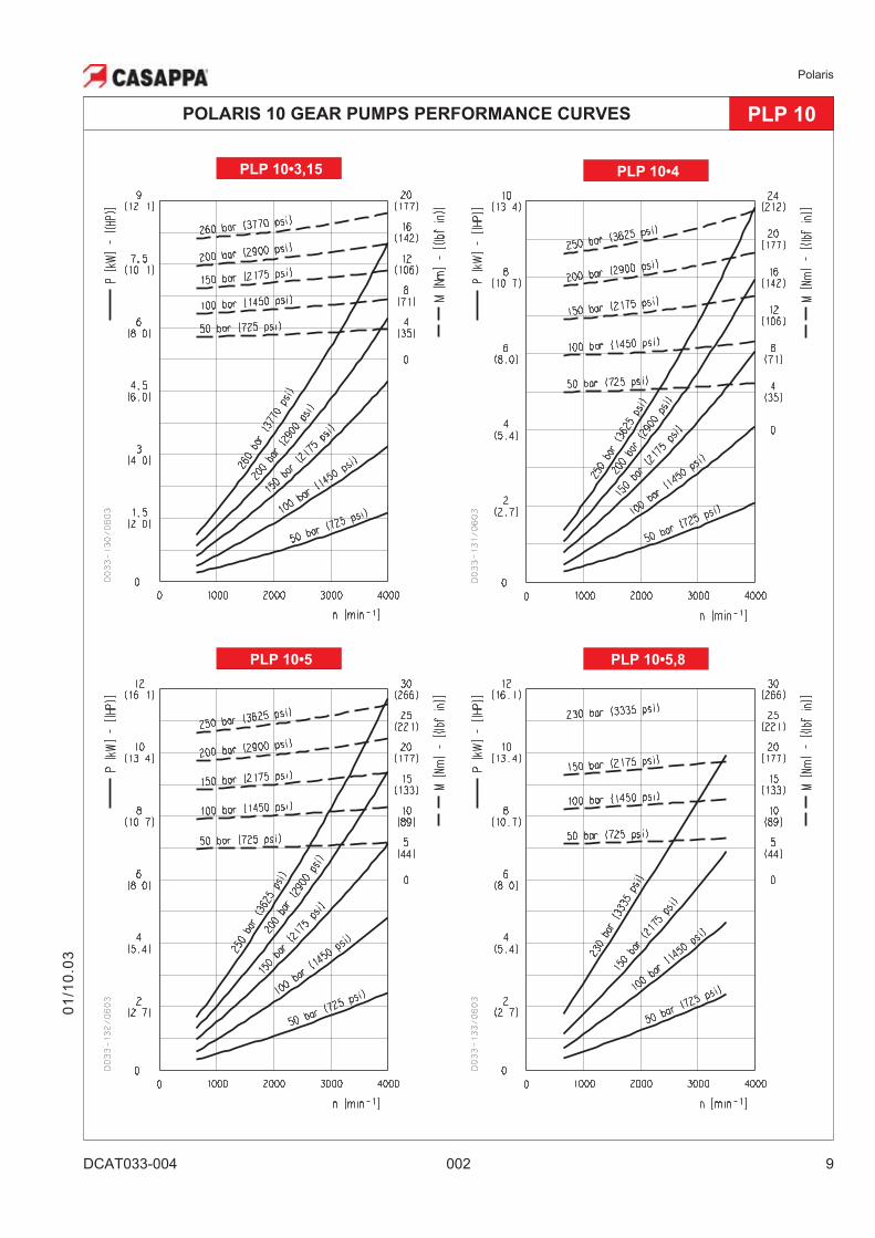
GENERAL DATA PUMPS AND MOTORS
Note: Diagrams providing approximate selection data will be found on subsequent pages.
DESIGN CALCULATIONS FOR MOTOR
Efficiencies
Pumps Motors
�v= �v (V,�p, n) Volumetric efficiency (� 0,97) (� 0,96)
�m= �m (V,�p, n) Mechanical efficiency (� 0,88) (� 0,85)
�t = �v • �m Overall efficiency (� 0,85) (� 0,82)
Q US gpm (l/min) Flow
M lbf in (Nm) Torque
P HP (kW) Power
V in3/rev (cm
3/rev) Displacement
n min-1
Speed
�p psi (bar) Pressure
DESIGN CALCULATIONS FOR PUMP
01
/10
.03
Q = V(cm3/rev) • �v • n • 10
-3[l/min]
M =�p (bar) • V (cm
3/rev)
[Nm]62,83 • �m
P =�p (bar) • V (cm
3/rev) • n
[kW]600 • 1000• �t
Q =V (cm
3/rev) • n • 10
-3
[l/min]�v
M =�p (bar) • V (cm
3/rev) • �m
[Nm]62,83
P =�p (bar) • V (cm
3/rev) • n• �t
[kW]600 • 1000
Polaris
DCAT033-004 002 7
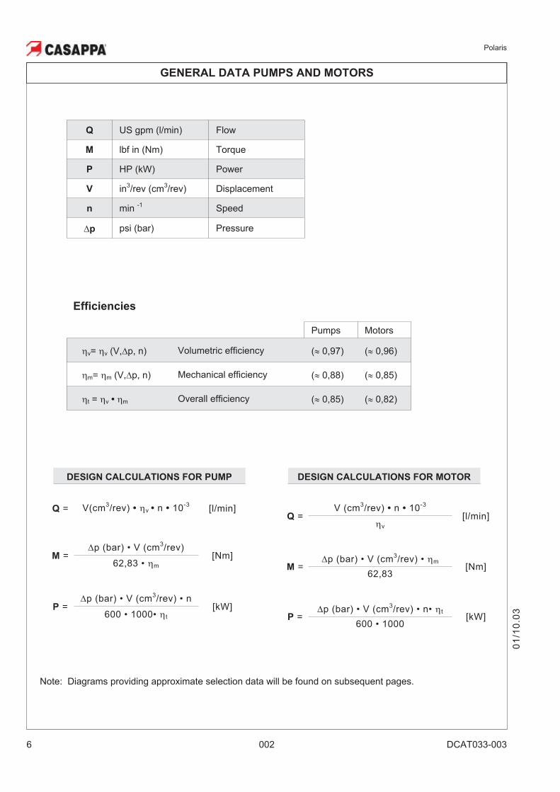
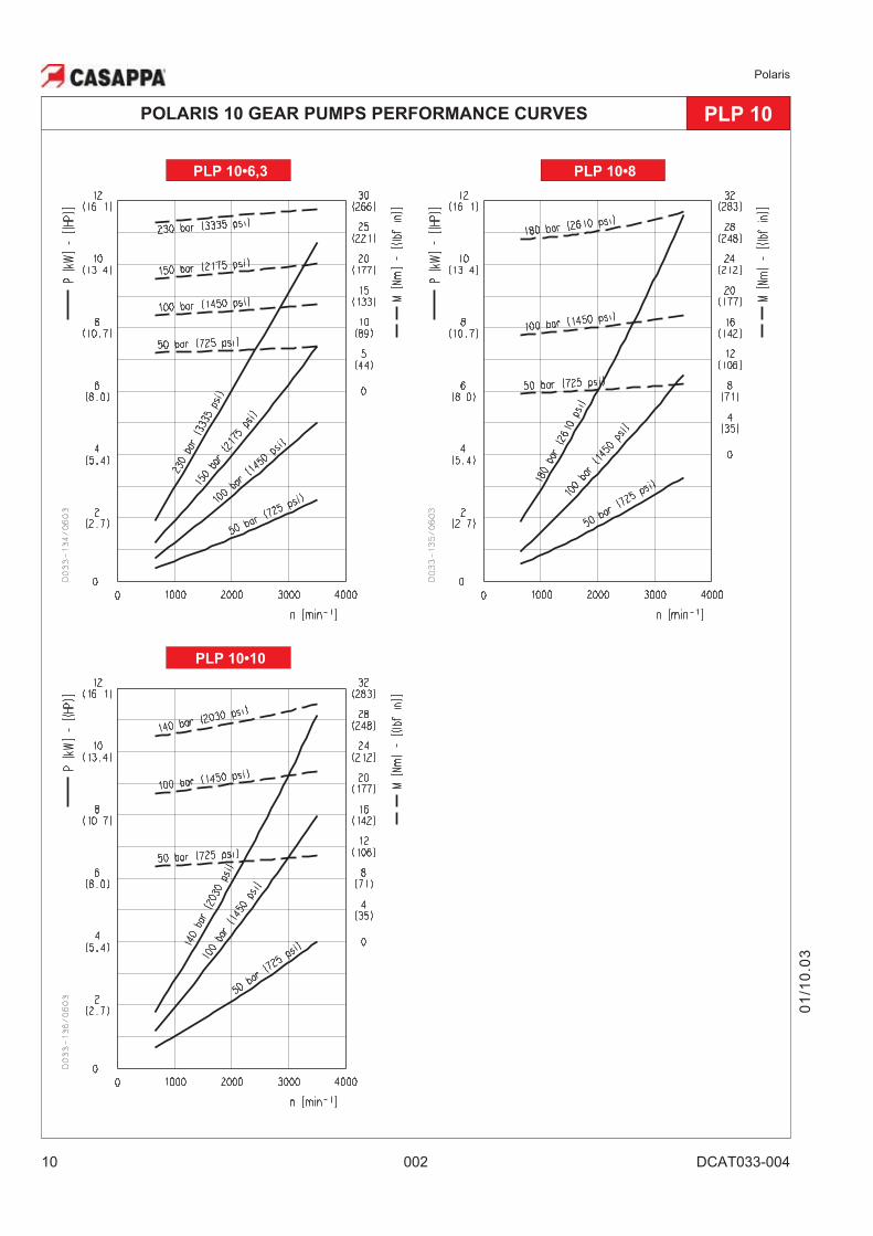
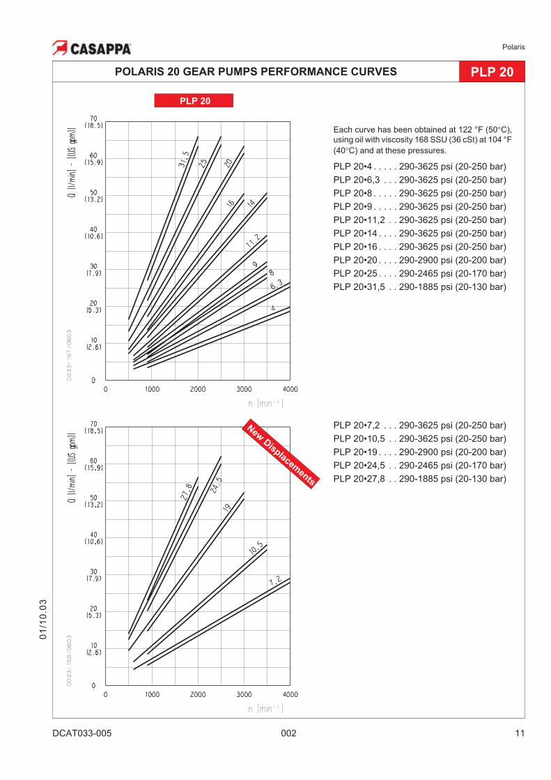
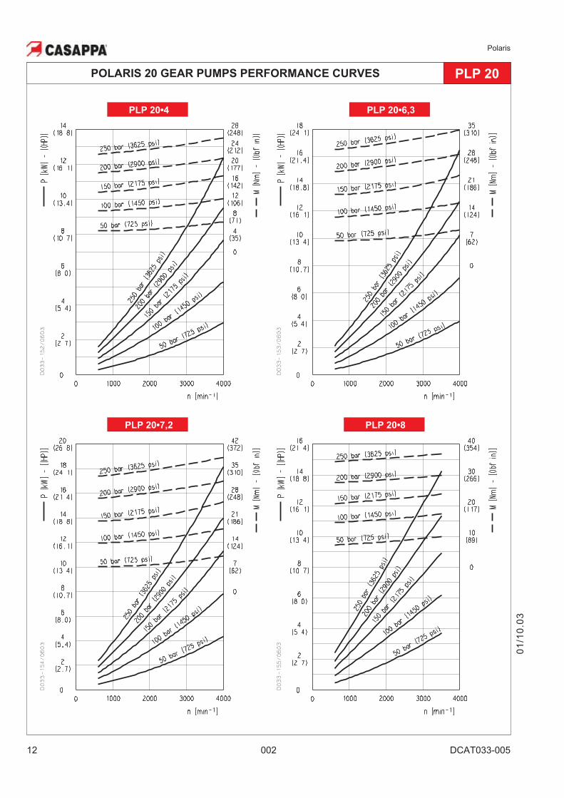
Each curve has been obtained at 122 °F (50�C),
using oil with viscosity 168 SSU (36 cSt) at 104 °F
(40�C) and at these pressures.
PLP 10•1 . . . . . 290-3770 psi (20-260 bar)
PLP 10•2 . . . . . 290-3770 psi (20-260 bar)
PLP 10•3,15 . . 290-3770 psi (20-260 bar)
PLP 10•4 . . . . . 290-3625 psi (20-250 bar)
PLP 10•5 . . . . . 290-3625 psi (20-250 bar)
PLP 10•6,3 . . . 290-3335 psi (20-230 bar)
PLP 10•8 . . . . . 290-2610 psi (20-180 bar)
PLP 10•10 . . . . 290-2030 psi (20-140 bar)
01
/10
.03
POLARIS 10 GEAR PUMPS PERFORMANCE CURVES PLP 10
PLP 10
PLP 10•1,5 . . . 290-3770 psi (20-260 bar)
PLP 10•2,5 . . . 290-3770 psi (20-260 bar)
PLP 10•5,8 . . . 290-3335 psi (20-230 bar)
Polaris
8 002 DCAT033-004
01
/10
.03
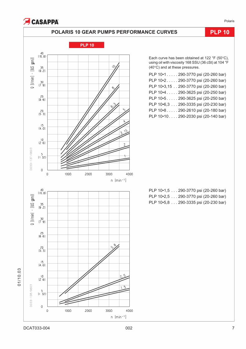
POLARIS 10 GEAR PUMPS PERFORMANCE CURVES PLP 10
PLP 10•2 PLP 10•2,5
PLP 10•1 PLP 10•1,5
Polaris
DCAT033-004 002 9
01
/10
.03
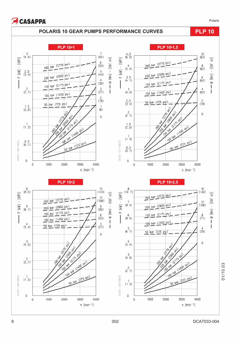
POLARIS 10 GEAR PUMPS PERFORMANCE CURVES PLP 10
PLP 10•5 PLP 10•5,8
PLP 10•3,15 PLP 10•4
Polaris
10 002 DCAT033-004
01
/10
.03
POLARIS 10 GEAR PUMPS PERFORMANCE CURVES PLP 10
PLP 10•10
PLP 10•8PLP 10•6,3
Polaris
DCAT033-005 002 11
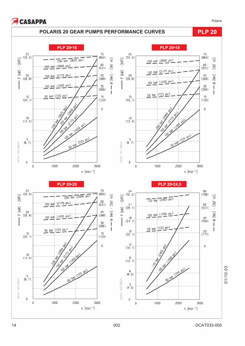
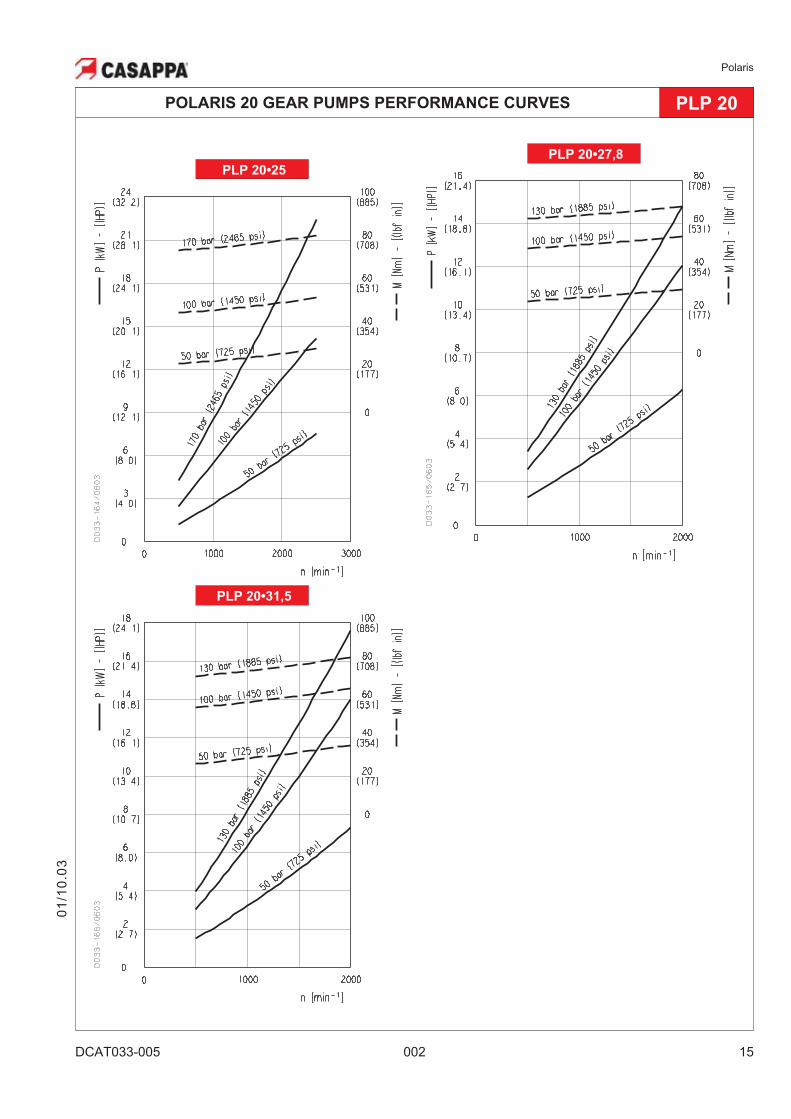
Each curve has been obtained at 122 °F (50�C),
using oil with viscosity 168 SSU (36 cSt) at 104 °F
(40�C) and at these pressures.
PLP 20•4 . . . . . 290-3625 psi (20-250 bar)
PLP 20•6,3 . . . 290-3625 psi (20-250 bar)
PLP 20•8 . . . . . 290-3625 psi (20-250 bar)
PLP 20•9 . . . . . 290-3625 psi (20-250 bar)
PLP 20•11,2 . . 290-3625 psi (20-250 bar)
PLP 20•14 . . . . 290-3625 psi (20-250 bar)
PLP 20•16 . . . . 290-3625 psi (20-250 bar)
PLP 20•20 . . . . 290-2900 psi (20-200 bar)
PLP 20•25 . . . . 290-2465 psi (20-170 bar)
PLP 20•31,5 . . 290-1885 psi (20-130 bar)
PLP 20
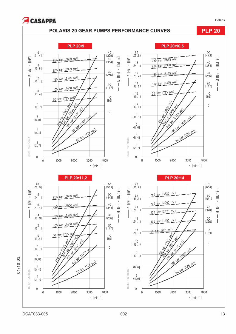
POLARIS 20 GEAR PUMPS PERFORMANCE CURVES PLP 20
01
/10
.03
New
Disp
lacemen
ts
PLP 20•7,2 . . . 290-3625 psi (20-250 bar)
PLP 20•10,5 . . 290-3625 psi (20-250 bar)
PLP 20•19 . . . . 290-2900 psi (20-200 bar)
PLP 20•24,5 . . 290-2465 psi (20-170 bar)
PLP 20•27,8 . . 290-1885 psi (20-130 bar)
Polaris
12 002 DCAT033-005
PLP 20•8
POLARIS 20 GEAR PUMPS PERFORMANCE CURVES PLP 20
01
/10
.03
PLP 20•4 PLP 20•6,3
PLP 20•7,2
Polaris
DCAT033-005 002 13
PLP 20•14
POLARIS 20 GEAR PUMPS PERFORMANCE CURVES PLP 20
01
/10
.03
PLP 20•10,5
PLP 20•11,2
PLP 20•9
Polaris
14 002 DCAT033-005
PLP 20•24,5
POLARIS 20 GEAR PUMPS PERFORMANCE CURVES PLP 20
01
/10
.03
PLP 20•19
PLP 20•20
PLP 20•16
Polaris
DCAT033-005 002 15
POLARIS 20 GEAR PUMPS PERFORMANCE CURVES PLP 20
PLP 20•27,8
PLP 20•31,5
01
/10
.03
PLP 20•25
Polaris
16 002 DCAT033-006
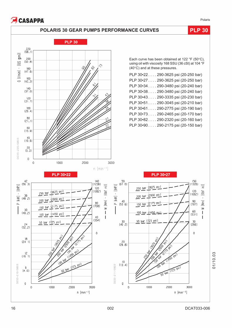
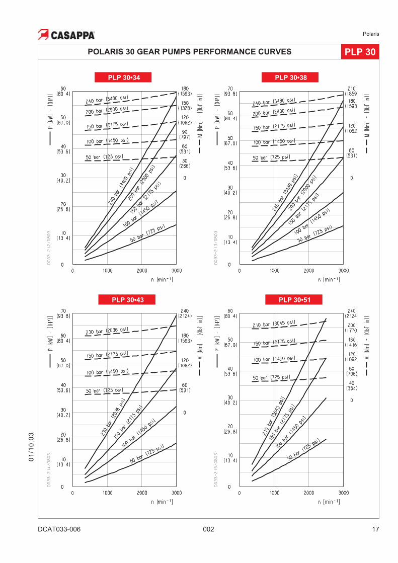
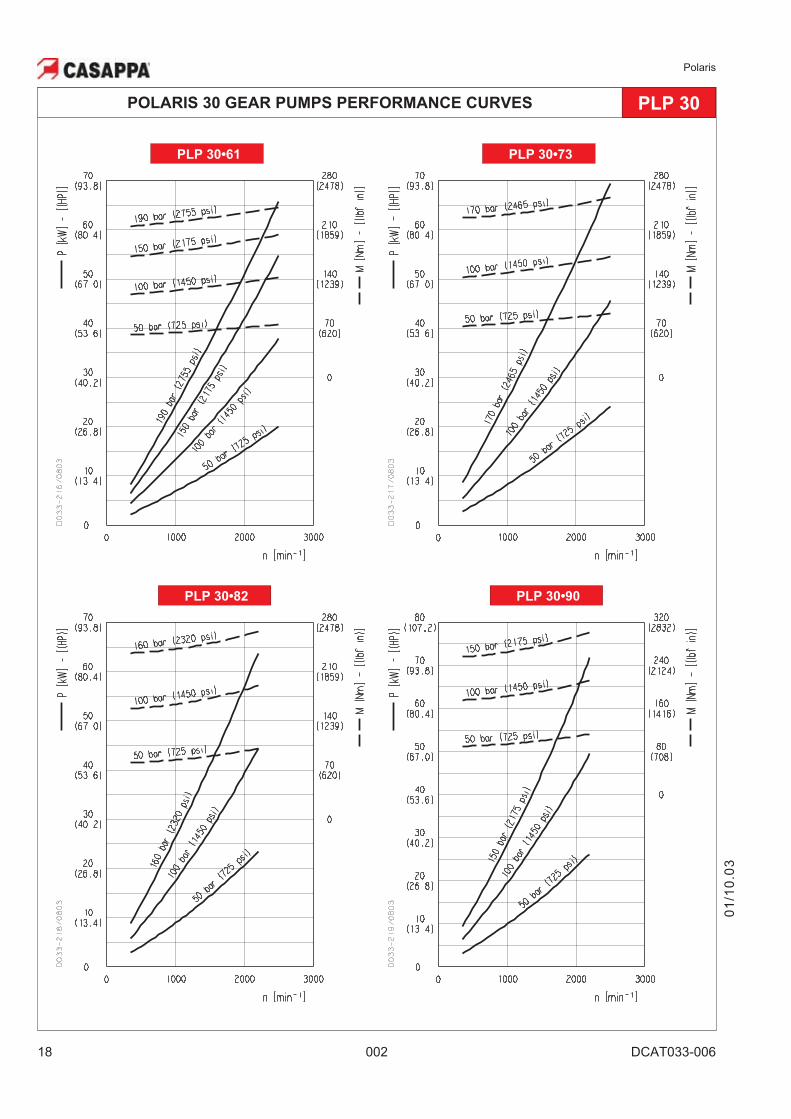
POLARIS 30 GEAR PUMPS PERFORMANCE CURVES PLP 30
PLP 30
Each curve has been obtained at 122 °F (50�C),
using oil with viscosity 168 SSU (36 cSt) at 104 °F
(40�C) and at these pressures.
PLP 30•22 . . . . 290-3625 psi (20-250 bar)
PLP 30•27 . . . . 290-3625 psi (20-250 bar)
PLP 30•34 . . . . 290-3480 psi (20-240 bar)
PLP 30•38 . . . . 290-3480 psi (20-240 bar)
PLP 30•43 . . . . 290-3335 psi (20-230 bar)
PLP 30•51 . . . . 290-3045 psi (20-210 bar)
PLP 30•61 . . . . 290-2775 psi (20-190 bar)
PLP 30•73 . . . . 290-2465 psi (20-170 bar)
PLP 30•82 . . . . 290-2320 psi (20-160 bar)
PLP 30•90 . . . . 290-2175 psi (20-150 bar)
PLP 30•22 PLP 30•27
01
/10
.03
Polaris
DCAT033-006 002 17
POLARIS 30 GEAR PUMPS PERFORMANCE CURVES PLP 30
PLP 30•43 PLP 30•51
PLP 30•38PLP 30•34
01
/10
.03
Polaris
18 002 DCAT033-006
POLARIS 30 GEAR PUMPS PERFORMANCE CURVES PLP 30
PLP 30•82 PLP 30•90
PLP 30•61 PLP 30•73
01
/10
.03
Polaris
DCAT033-007 002 19
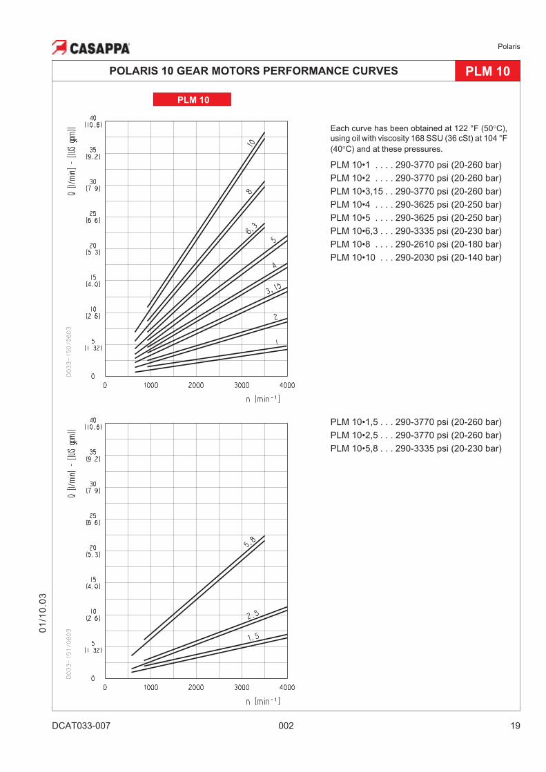
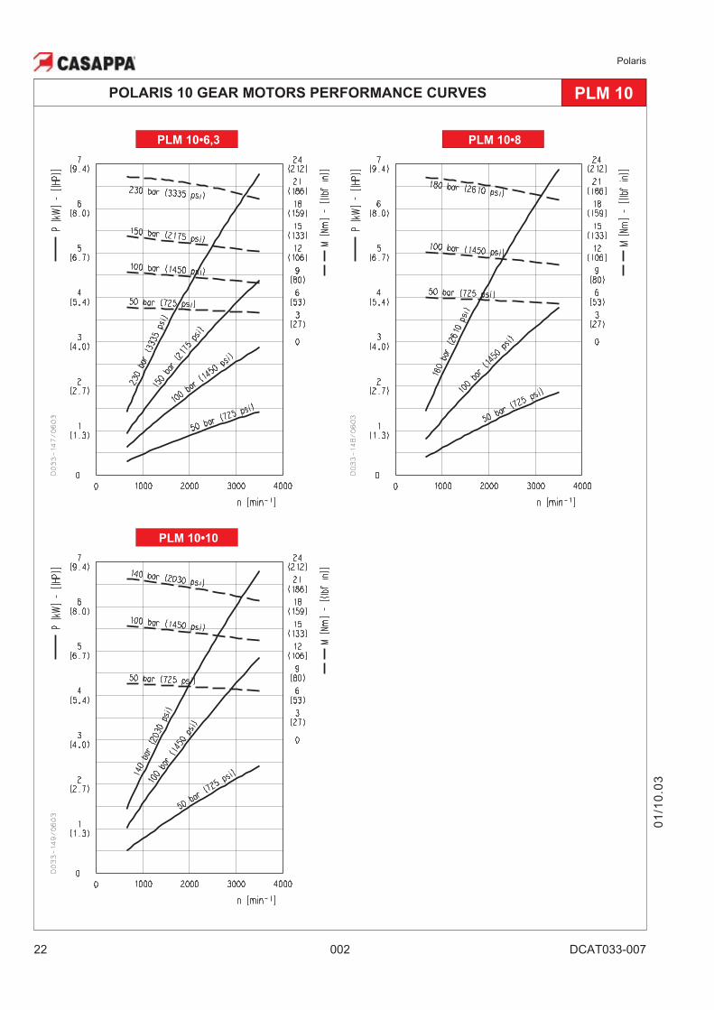
Each curve has been obtained at 122 °F (50�C),
using oil with viscosity 168 SSU (36 cSt) at 104 °F
(40�C) and at these pressures.
PLM 10•1 . . . . 290-3770 psi (20-260 bar)
PLM 10•2 . . . . 290-3770 psi (20-260 bar)
PLM 10•3,15 . . 290-3770 psi (20-260 bar)
PLM 10•4 . . . . 290-3625 psi (20-250 bar)
PLM 10•5 . . . . 290-3625 psi (20-250 bar)
PLM 10•6,3 . . . 290-3335 psi (20-230 bar)
PLM 10•8 . . . . 290-2610 psi (20-180 bar)
PLM 10•10 . . . 290-2030 psi (20-140 bar)
01
/10
.03
POLARIS 10 GEAR MOTORS PERFORMANCE CURVES PLM 10
PLM 10
PLM 10•1,5 . . . 290-3770 psi (20-260 bar)
PLM 10•2,5 . . . 290-3770 psi (20-260 bar)
PLM 10•5,8 . . . 290-3335 psi (20-230 bar)
Polaris
20 002 DCAT033-007
01
/10
.03
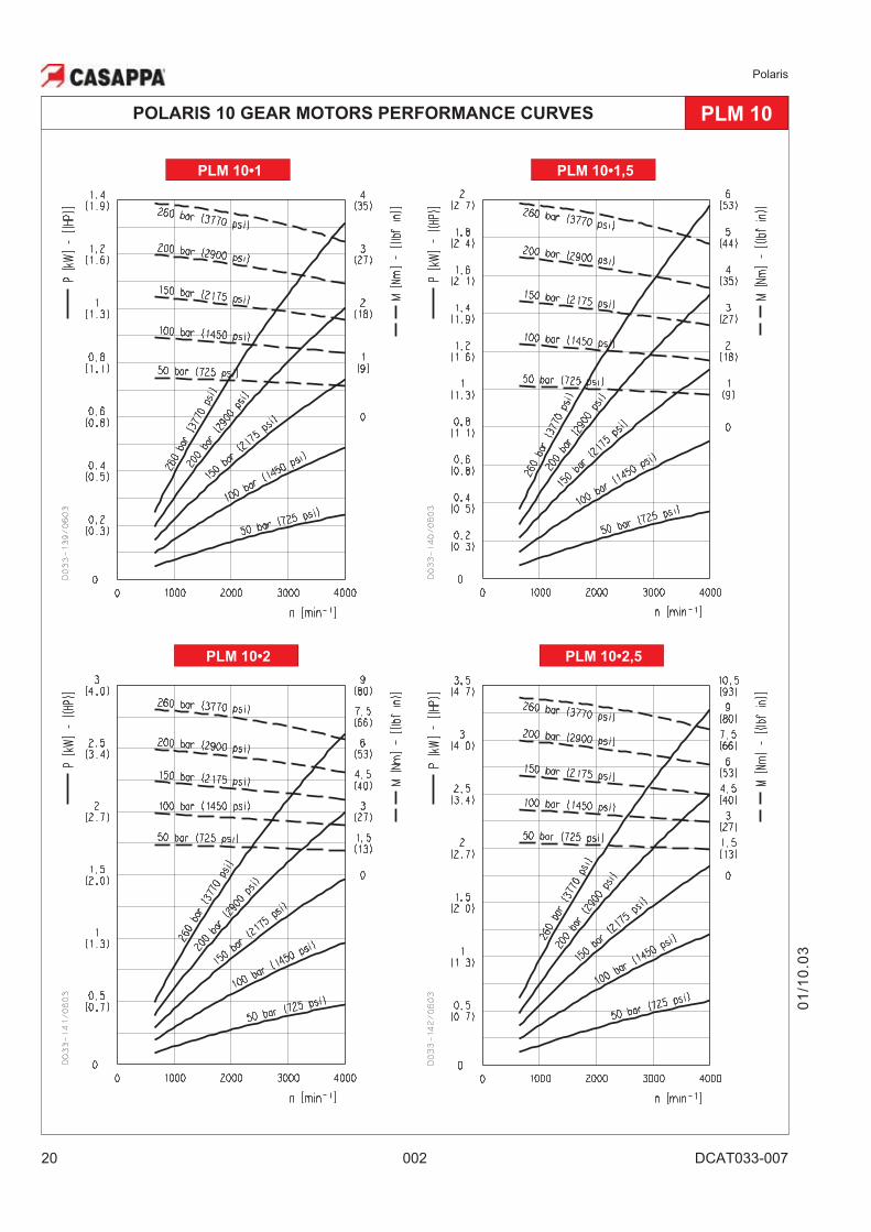
POLARIS 10 GEAR MOTORS PERFORMANCE CURVES PLM 10
PLM 10•2 PLM 10•2,5
PLM 10•1 PLM 10•1,5
Polaris
DCAT033-007 002 21
01
/10
.03
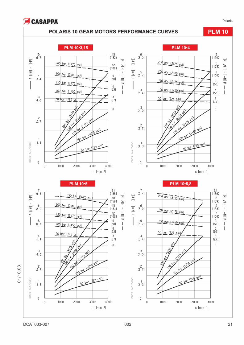
POLARIS 10 GEAR MOTORS PERFORMANCE CURVES PLM 10
PLM 10•5 PLM 10•5,8
PLM 10•3,15 PLM 10•4
Polaris
22 002 DCAT033-007
01
/10
.03
POLARIS 10 GEAR MOTORS PERFORMANCE CURVES PLM 10
PLM 10•10
PLM 10•8PLM 10•6,3
Polaris
DCAT033-008 002 23
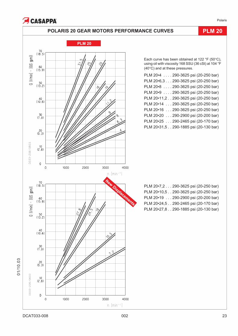
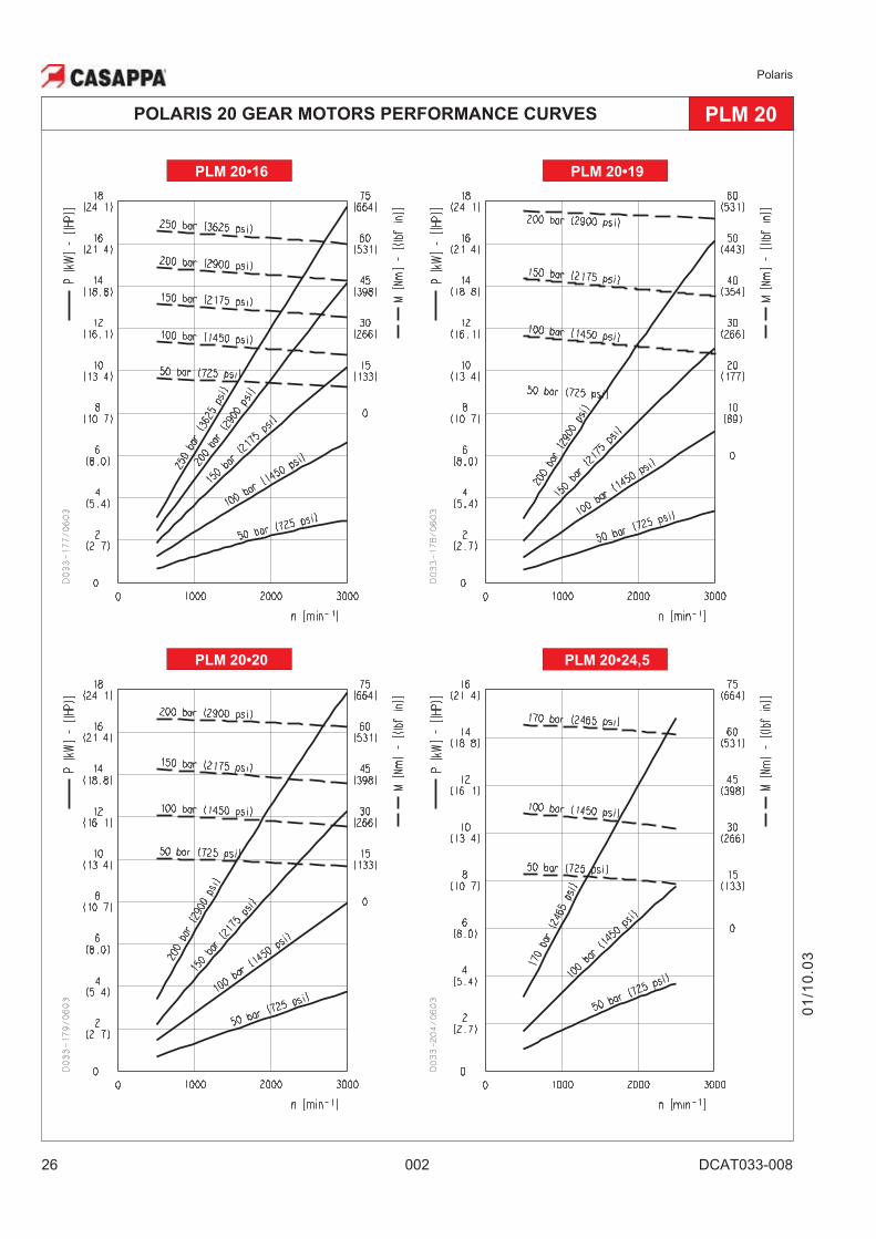
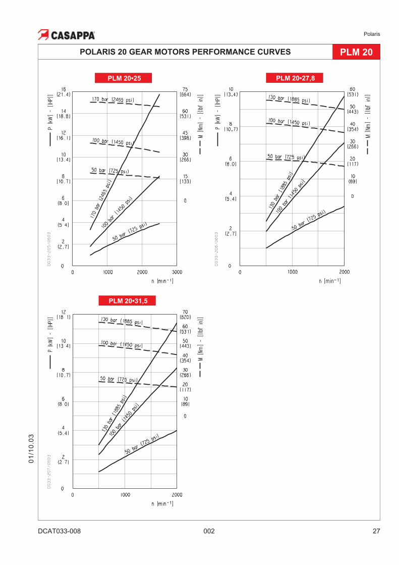
Each curve has been obtained at 122 °F (50�C),
using oil with viscosity 168 SSU (36 cSt) at 104 °F
(40�C) and at these pressures.
PLM 20•4 . . . . 290-3625 psi (20-250 bar)
PLM 20•6,3 . . . 290-3625 psi (20-250 bar)
PLM 20•8 . . . . 290-3625 psi (20-250 bar)
PLM 20•9 . . . . 290-3625 psi (20-250 bar)
PLM 20•11,2 . . 290-3625 psi (20-250 bar)
PLM 20•14 . . . 290-3625 psi (20-250 bar)
PLM 20•16 . . . 290-3625 psi (20-250 bar)
PLM 20•20 . . . 290-2900 psi (20-200 bar)
PLM 20•25 . . . 290-2465 psi (20-170 bar)
PLM 20•31,5 . . 290-1885 psi (20-130 bar)
PLM 20
POLARIS 20 GEAR MOTORS PERFORMANCE CURVES PLM 20
01
/10
.03
New
Disp
lacemen
ts
PLM 20•7,2 . . . 290-3625 psi (20-250 bar)
PLM 20•10,5 . . 290-3625 psi (20-250 bar)
PLM 20•19 . . . 290-2900 psi (20-200 bar)
PLM 20•24,5 . . 290-2465 psi (20-170 bar)
PLM 20•27,8 . . 290-1885 psi (20-130 bar)
Polaris
24 002 DCAT033-008
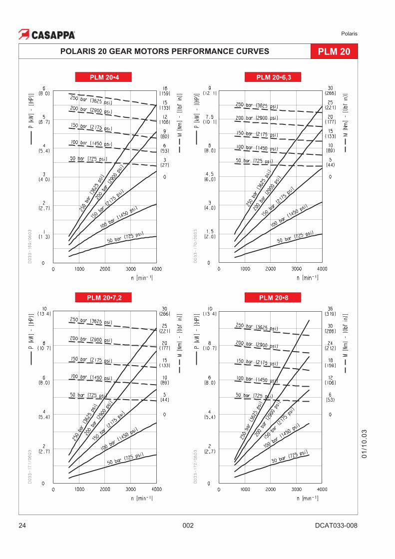
PLM 20•4 PLM 20•6,3
PLM 20•7,2 PLM 20•8
POLARIS 20 GEAR MOTORS PERFORMANCE CURVES PLM 20
01
/10
.03
Polaris
DCAT033-008 002 25
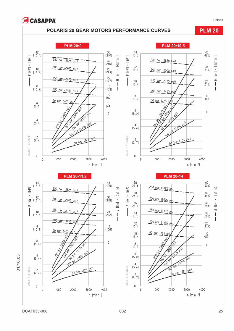
PLM 20•9
POLARIS 20 GEAR MOTORS PERFORMANCE CURVES PLM 20
01
/10
.03
PLM 20•11,2 PLM 20•14
PLM 20•10,5
Polaris
26 002 DCAT033-008
PLM 20•16 PLM 20•19
PLM 20•20 PLM 20•24,5
POLARIS 20 GEAR MOTORS PERFORMANCE CURVES PLM 20
01
/10
.03
Polaris
DCAT033-008 002 27
PLM 20•25
POLARIS 20 GEAR MOTORS PERFORMANCE CURVES PLM 20
01
/10
.03
PLM 20•31,5
PLM 20•27,8
Polaris
28 002 DCAT033-009
01
/10
.03
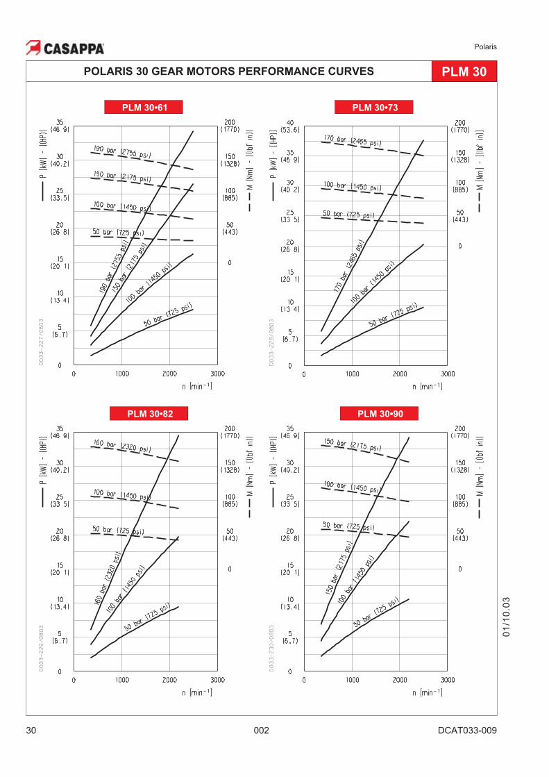
POLARIS 30 GEAR MOTORS PERFORMANCE CURVES PLM 30
PLM 30
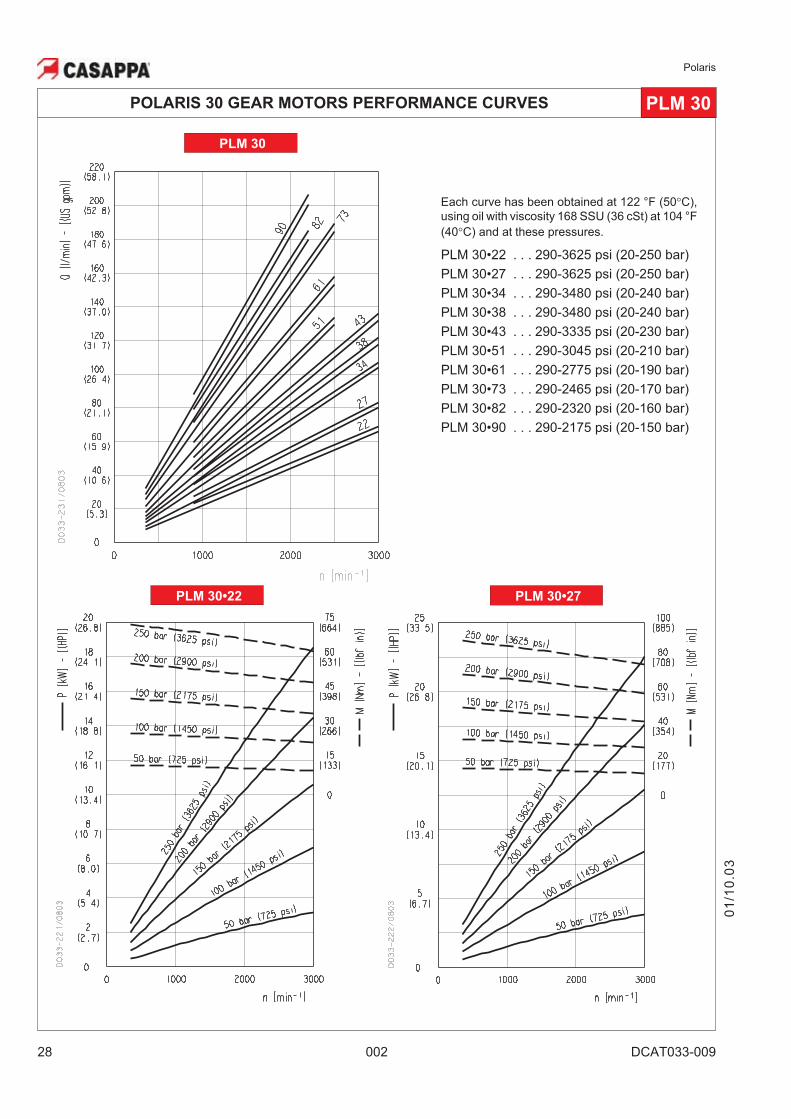
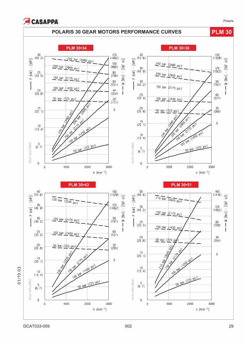
Each curve has been obtained at 122 °F (50�C),
using oil with viscosity 168 SSU (36 cSt) at 104 °F
(40�C) and at these pressures.
PLM 30•22 . . . 290-3625 psi (20-250 bar)
PLM 30•27 . . . 290-3625 psi (20-250 bar)
PLM 30•34 . . . 290-3480 psi (20-240 bar)
PLM 30•38 . . . 290-3480 psi (20-240 bar)
PLM 30•43 . . . 290-3335 psi (20-230 bar)
PLM 30•51 . . . 290-3045 psi (20-210 bar)
PLM 30•61 . . . 290-2775 psi (20-190 bar)
PLM 30•73 . . . 290-2465 psi (20-170 bar)
PLM 30•82 . . . 290-2320 psi (20-160 bar)
PLM 30•90 . . . 290-2175 psi (20-150 bar)
PLM 30•22 PLM 30•27
Polaris
DCAT033-009 002 29
01
/10
.03
POLARIS 30 GEAR MOTORS PERFORMANCE CURVES PLM 30
PLM 30•43 PLM 30•51
PLM 30•38PLM 30•34
Polaris
30 002 DCAT033-009
POLARIS 30 GEAR MOTORS PERFORMANCE CURVES PLM 30
PLM 30•82 PLM 30•90
PLM 30•61 PLM 30•73
01
/10
.03
Polaris
DCAT033-010 002 31
01
/10
.03
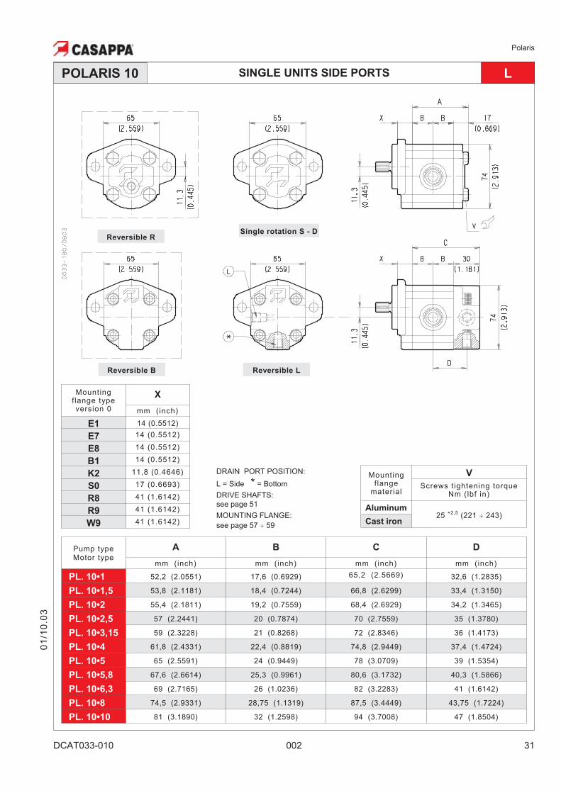
SINGLE UNITS SIDE PORTS LPOLARIS 10
Pump typeMotor type
A B C D
mm (inch) mm (inch) mm (inch) mm (inch)
PL. 10•1 52,2 (2.0551) 17,6 (0.6929) 65,2 (2.5669) 32,6 (1.2835)
PL. 10•1,5 53,8 (2.1181) 18,4 (0.7244) 66,8 (2.6299) 33,4 (1.3150)
PL. 10•2 55,4 (2.1811) 19,2 (0.7559) 68,4 (2.6929) 34,2 (1.3465)
PL. 10•2,5 57 (2.2441) 20 (0.7874) 70 (2.7559) 35 (1.3780)
PL. 10•3,15 59 (2.3228) 21 (0.8268) 72 (2.8346) 36 (1.4173)
PL. 10•4 61,8 (2.4331) 22,4 (0.8819) 74,8 (2.9449) 37,4 (1.4724)
PL. 10•5 65 (2.5591) 24 (0.9449) 78 (3.0709) 39 (1.5354)
PL. 10•5,8 67,6 (2.6614) 25,3 (0.9961) 80,6 (3.1732) 40,3 (1.5866)
PL. 10•6,3 69 (2.7165) 26 (1.0236) 82 (3.2283) 41 (1.6142)
PL. 10•8 74,5 (2.9331) 28,75 (1.1319) 87,5 (3.4449) 43,75 (1.7224)
PL. 10•10 81 (3.1890) 32 (1.2598) 94 (3.7008) 47 (1.8504)
DRAIN PORT POSITION:
L = Side * = Bottom
DRIVE SHAFTS:
see page 51
MOUNTING FLANGE:
see page 57 � 59
Mountingflange
material
V
Screws tightening torqueNm (lbf in)
Aluminum25
+2,5(221 � 243)
Cast iron
Reversible RSingle rotation S - D
Reversible B Reversible L
Mountingflange typeversion 0
X
mm (inch)
E1 14 (0.5512)
E7 14 (0.5512)
E8 14 (0.5512)
B1 14 (0.5512)
K2 11,8 (0.4646)
S0 17 (0.6693)
R8 41 (1.6142)
R9 41 (1.6142)
W9 41 (1.6142)
Polaris
32 002 DCAT033-010
01
/10
.03
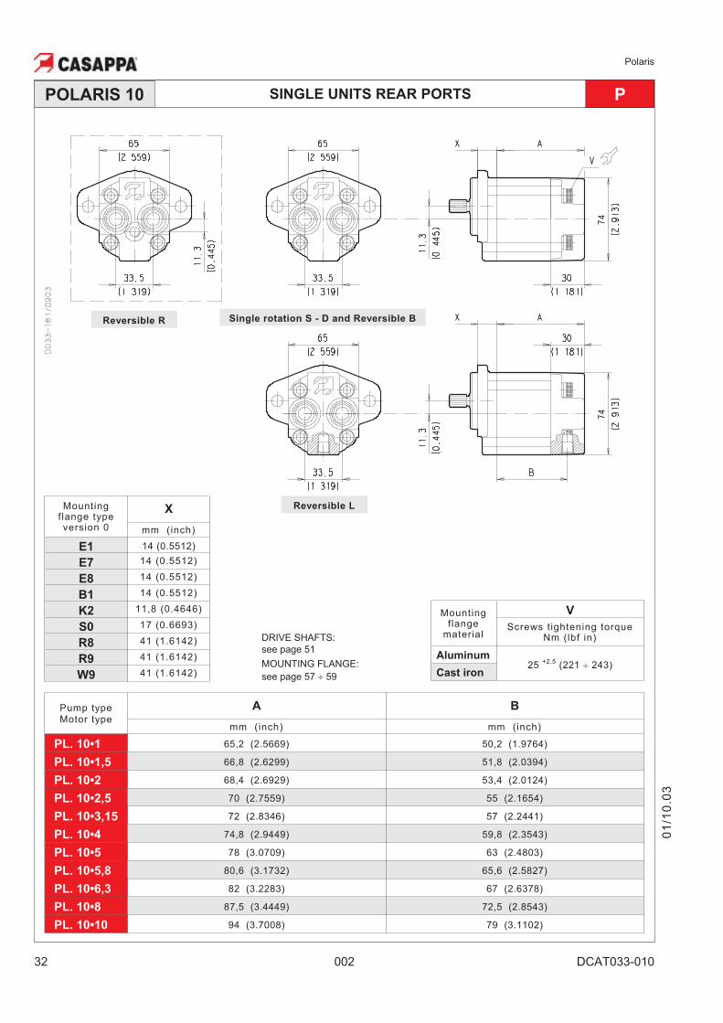
SINGLE UNITS REAR PORTS PPOLARIS 10
Pump typeMotor type
A B
mm (inch) mm (inch)
PL. 10•1 65,2 (2.5669) 50,2 (1.9764)
PL. 10•1,5 66,8 (2.6299) 51,8 (2.0394)
PL. 10•2 68,4 (2.6929) 53,4 (2.0124)
PL. 10•2,5 70 (2.7559) 55 (2.1654)
PL. 10•3,15 72 (2.8346) 57 (2.2441)
PL. 10•4 74,8 (2.9449) 59,8 (2.3543)
PL. 10•5 78 (3.0709) 63 (2.4803)
PL. 10•5,8 80,6 (3.1732) 65,6 (2.5827)
PL. 10•6,3 82 (3.2283) 67 (2.6378)
PL. 10•8 87,5 (3.4449) 72,5 (2.8543)
PL. 10•10 94 (3.7008) 79 (3.1102)
Single rotation S - D and Reversible BReversible R
Reversible L
DRIVE SHAFTS:
see page 51
MOUNTING FLANGE:
see page 57 � 59
Mountingflange
material
V
Screws tightening torqueNm (lbf in)
Aluminum25
+2,5(221 � 243)
Cast iron
Mountingflange typeversion 0
X
mm (inch)
E1 14 (0.5512)
E7 14 (0.5512)
E8 14 (0.5512)
B1 14 (0.5512)
K2 11,8 (0.4646)
S0 17 (0.6693)
R8 41 (1.6142)
R9 41 (1.6142)
W9 41 (1.6142)
Polaris
DCAT033-010 002 33
01
/10
.03
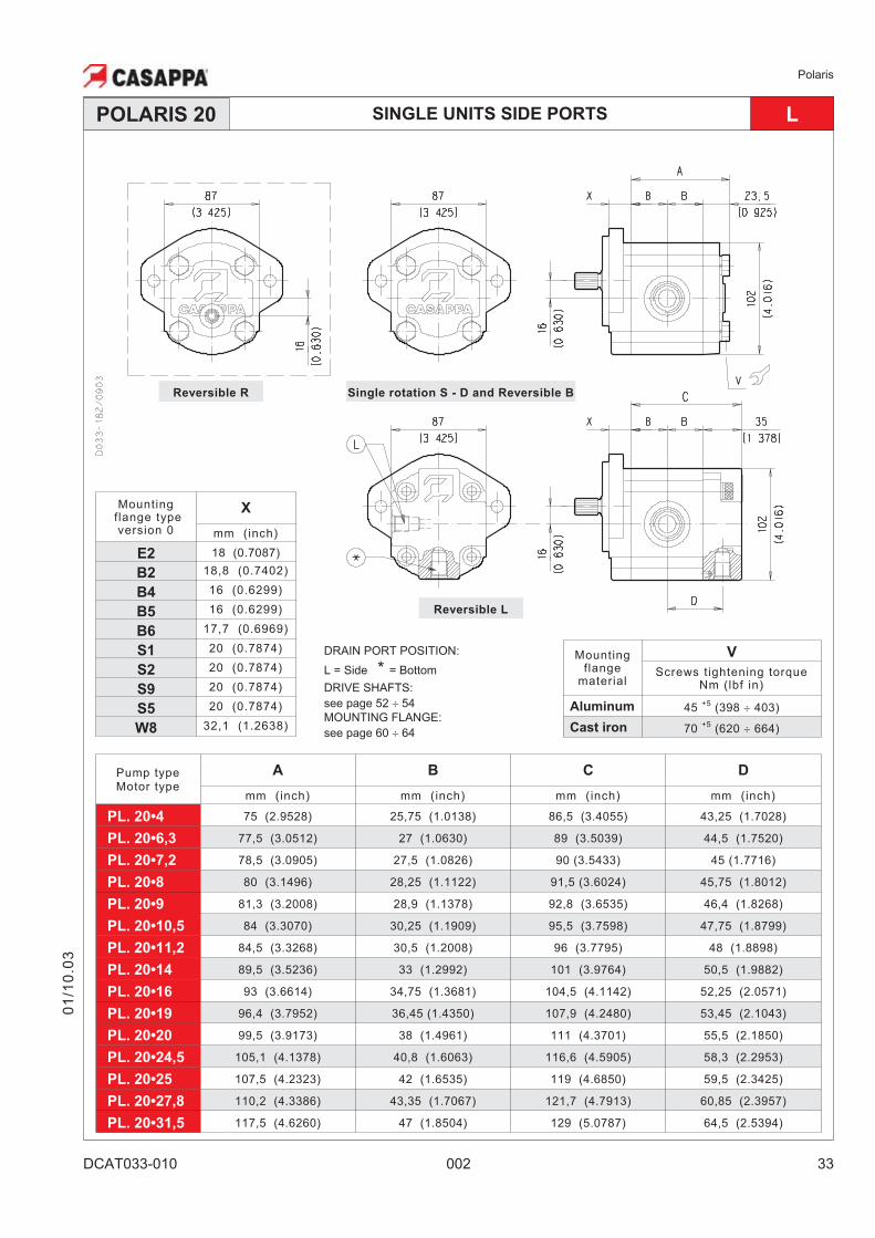
SINGLE UNITS SIDE PORTS LPOLARIS 20
Pump typeMotor type
A B C D
mm (inch) mm (inch) mm (inch) mm (inch)
PL. 20•4 75 (2.9528) 25,75 (1.0138) 86,5 (3.4055) 43,25 (1.7028)
PL. 20•6,3 77,5 (3.0512) 27 (1.0630) 89 (3.5039) 44,5 (1.7520)
PL. 20•7,2 78,5 (3.0905) 27,5 (1.0826) 90 (3.5433) 45 (1.7716)
PL. 20•8 80 (3.1496) 28,25 (1.1122) 91,5 (3.6024) 45,75 (1.8012)
PL. 20•9 81,3 (3.2008) 28,9 (1.1378) 92,8 (3.6535) 46,4 (1.8268)
PL. 20•10,5 84 (3.3070) 30,25 (1.1909) 95,5 (3.7598) 47,75 (1.8799)
PL. 20•11,2 84,5 (3.3268) 30,5 (1.2008) 96 (3.7795) 48 (1.8898)
PL. 20•14 89,5 (3.5236) 33 (1.2992) 101 (3.9764) 50,5 (1.9882)
PL. 20•16 93 (3.6614) 34,75 (1.3681) 104,5 (4.1142) 52,25 (2.0571)
PL. 20•19 96,4 (3.7952) 36,45 (1.4350) 107,9 (4.2480) 53,45 (2.1043)
PL. 20•20 99,5 (3.9173) 38 (1.4961) 111 (4.3701) 55,5 (2.1850)
PL. 20•24,5 105,1 (4.1378) 40,8 (1.6063) 116,6 (4.5905) 58,3 (2.2953)
PL. 20•25 107,5 (4.2323) 42 (1.6535) 119 (4.6850) 59,5 (2.3425)
PL. 20•27,8 110,2 (4.3386) 43,35 (1.7067) 121,7 (4.7913) 60,85 (2.3957)
PL. 20•31,5 117,5 (4.6260) 47 (1.8504) 129 (5.0787) 64,5 (2.5394)
Mountingflange
material
V
Screws tightening torqueNm (lbf in)
Aluminum 45+5
(398 � 403)
Cast iron 70+5
(620 � 664)
Reversible R
DRAIN PORT POSITION:
L = Side * = Bottom
DRIVE SHAFTS:
see page 52 � 54
MOUNTING FLANGE:
see page 60 � 64
Reversible L
Single rotation S - D and Reversible B
Mountingflange typeversion 0
X
mm (inch)
E2 18 (0.7087)
B2 18,8 (0.7402)
B4 16 (0.6299)
B5 16 (0.6299)
B6 17,7 (0.6969)
S1 20 (0.7874)
S2 20 (0.7874)
S9 20 (0.7874)
S5 20 (0.7874)
W8 32,1 (1.2638)
Polaris
34 002 DCAT033-010
01
/10
.03
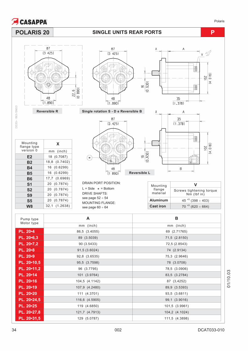
SINGLE UNITS REAR PORTS PPOLARIS 20
DRAIN PORT POSITION:
L = Side * = Bottom
DRIVE SHAFTS:
see page 52 � 54
MOUNTING FLANGE:
see page 60 � 64
Mountingflange
material
V
Screws tightening torqueNm (lbf in)
Aluminum 45+5
(398 � 403)
Cast iron 70+5
(620 � 664)
Single rotation S - D e Reversible BReversible R
Reversible L
Pump typeMotor type
A B
mm (inch) mm (inch)
PL. 20•4 86,5 (3.4055) 69 (2.71765)
PL. 20•6,3 89 (3.5039) 71,5 (2.8150)
PL. 20•7,2 90 (3.5433) 72,5 (2.8543)
PL. 20•8 91,5 (3.6024) 74 (2.9134)
PL. 20•9 92,8 (3.6535) 75,3 (2.9646)
PL. 20•10,5 95,5 (3.7598) 78 (3.0708)
PL. 20•11,2 96 (3.7795) 78,5 (3.0906)
PL. 20•14 101 (3.9764) 83,5 (3.2784)
PL. 20•16 104,5 (4.1142) 87 (3,4252)
PL. 20•19 107,9 (4.2480) 89,9 (3.5393)
PL. 20•20 111 (4.3701) 93,5 (3.6811)
PL. 20•24,5 116,6 (4.5905) 99,1 (3.9016)
PL. 20•25 119 (4.6850) 101,5 (3.9961)
PL. 20•27,8 121,7 (4.7913) 104,2 (4.1024)
PL. 20•31,5 129 (5.0787) 111,5 (4.3898)
Mountingflange typeversion 0
X
mm (inch)
E2 18 (0.7087)
B2 18,8 (0.7402)
B4 16 (0.6299)
B5 16 (0.6299)
B6 17,7 (0.6969)
S1 20 (0.7874)
S2 20 (0.7874)
S9 20 (0.7874)
S5 20 (0.7874)
W8 32,1 (1.2638)
Polaris
DCAT033-010 002 35
01
/10
.03
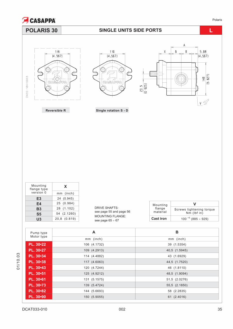
SINGLE UNITS SIDE PORTS LPOLARIS 30
Pump typeMotor type
A B
mm (inch) mm (inch)
PL. 30•22 106 (4.1732) 39 (1.5354)
PL. 30•27 109 (4.2913) 40,5 (1.5945)
PL. 30•34 114 (4.4882) 43 (1.6929)
PL. 30•38 117 (4.6063) 44,5 (1.7520)
PL. 30•43 120 (4.7244) 46 (1.8110)
PL. 30•51 125 (4.9212) 48,5 (1.9094)
PL. 30•61 131 (5.1575) 51,5 (2.0276)
PL. 30•73 139 (5.4724) 55,5 (2.1850)
PL. 30•82 144 (5.6693) 58 (2.2835)
PL. 30•90 150 (5.9055) 61 (2.4016)
Mountingflange
material
V
Screws tightening torqueNm (lbf in)
Cast iron 100+5
(885 � 929)
Reversible R Single rotation S - D
Mountingflange typeversion 0
X
mm (inch)
E3 24 (0.945)
E4 25 (0.984)
B3 28 (1.102)
S5 54 (2.1260)
U3 20,8 (0.819)
DRIVE SHAFTS:
see page 55 and page 56
MOUNTING FLANGE:
see page 65 � 67
Polaris
36 002 DCAT033-011
MULTIPLE PUMPS
POLARIS series pumps can be coupled together in combination. Where the input power re-quirements of each section varies, that with the greater requirement must be at the drive shaftend, and progressively smaller to the rear.
Features and performances are the same as the corresponding single pumps, but pressuresmust be limited by the transmissible torque of the drive and connecting shafts. To have appro-priate data, use the formula below.
The maximum rotational speed is that of the lowest rated speed of the single units incorporated.
Available with common inlet and separated stages. For more information please consult ourtechnical sales department.
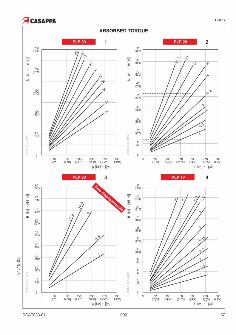
Example
Let us consider a double pump PLP20•14 + PLP20•4. If we suppose that we have to work withthe first pump at a pressure of 2900 psi (200 bar) and the second pump at a pressure of 2175 psi(150 bar), the graph 2 shows that the torque absorbed by PLP20•14 is 469 lbf in (53 Nm) and thePLP20•4 absorbs 115 lbf in (13 Nm) (acceptable value because it doesn’t exceed the maximumdrive shaft torque that is 973 lbf in (110 Nm), see page 39). The torque to be transmitted by thefirst drive shaft will thus be 469+115= 584 lbf in (53+13= 66 Nm), this value must not exceed theshaft’s maximum rated value.
DRIVE SHAFT SELECTION0
1/1
0.0
3
M lbf in (Nm) Torque
V in3/rev (cm
3/rev) Displacement
�p psi (bar) Pressure
�m= �m (V,�p, n) (� 0,88) Mechanical efficiency
M =�p (bar) • V (cm
3/rev)
[Nm]62,83 • �m
The torque absorbed from the shaft of the first pump results from the sum of the torques due toall single stages. The achieved value must not exceed the maximum torque limit given for theshaft of the first pump. Diagrams providing approximate selection data will be found on page 37.
Polaris
DCAT033-011 002 37
ABSORBED TORQUE
PLP 10 4
PLP 30 PLP 20 21
PLP 20 3
New
disp
lacemen
ts
01
/10
.03
Polaris
38 002 DCAT033-011
Intermediate RearFront
MAX 30 Nm (266 lbf in)
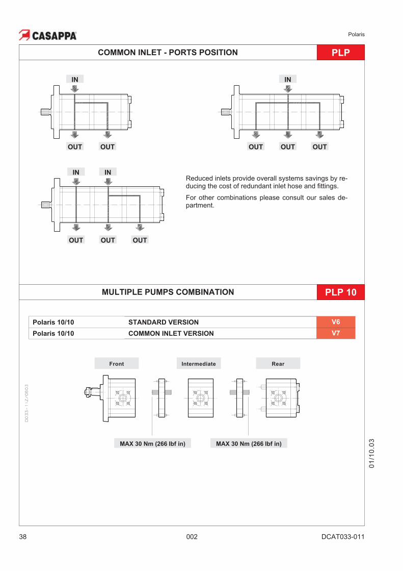
MULTIPLE PUMPS COMBINATION PLP 10
Polaris 10/10 STANDARD VERSION V6
Polaris 10/10 COMMON INLET VERSION V7
COMMON INLET - PORTS POSITION PLP
IN
OUT OUT OUT
IN
MAX 30 Nm (266 lbf in)
Reduced inlets provide overall systems savings by re-ducing the cost of redundant inlet hose and fittings.
For other combinations please consult our sales de-partment.
IN
OUT OUT
IN
OUT OUT OUT
01
/10
.03
Polaris
DCAT033-011 002 39
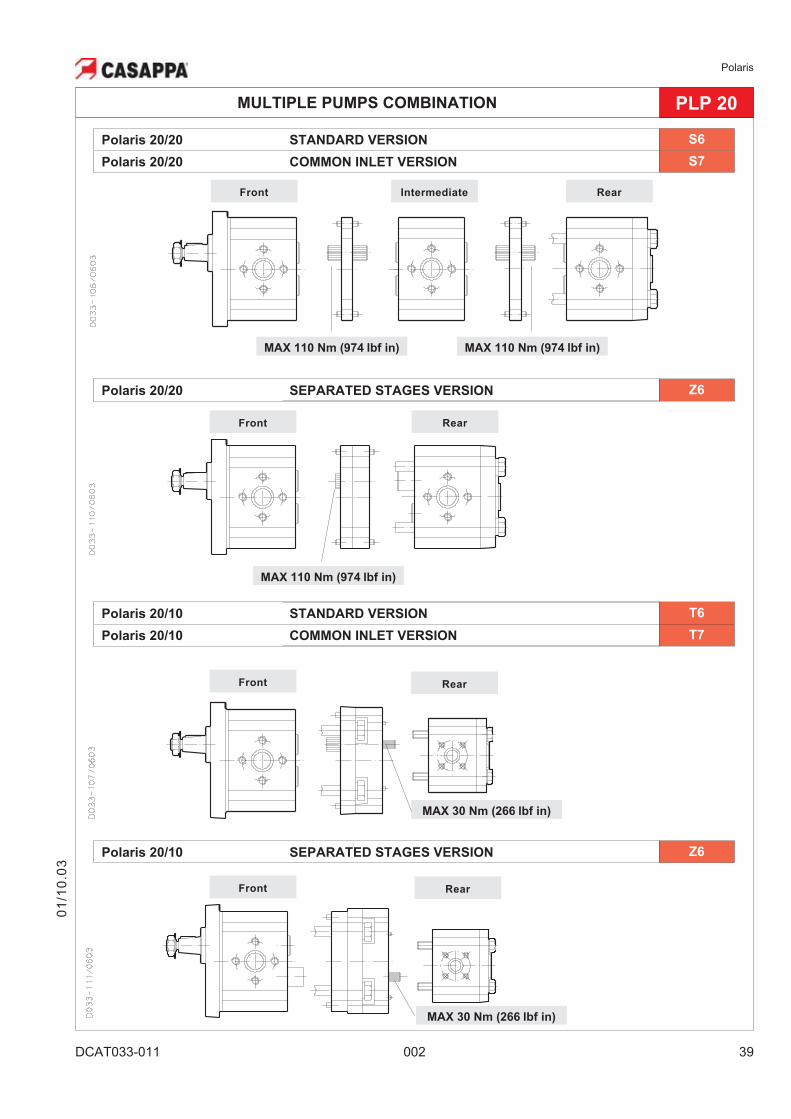
MULTIPLE PUMPS COMBINATION PLP 20
Polaris 20/10 SEPARATED STAGES VERSION Z6
Polaris 20/20 STANDARD VERSION S6
Polaris 20/20 COMMON INLET VERSION S7
Polaris 20/20 SEPARATED STAGES VERSION Z6
Polaris 20/10 STANDARD VERSION T6
Polaris 20/10 COMMON INLET VERSION T7
Intermediate
RearFront
RearFront
MAX 110 Nm (974 lbf in)
RearFront
MAX 30 Nm (266 lbf in)
RearFront
MAX 30 Nm (266 lbf in)
MAX 110 Nm (974 lbf in)
MAX 110 Nm (974 lbf in)
01
/10
.03
Polaris
40 002 DCAT033-011
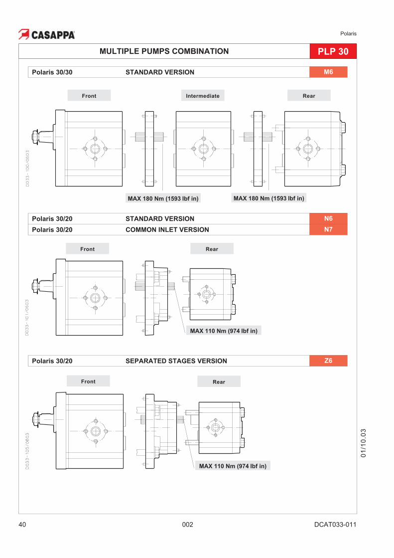
MULTIPLE PUMPS COMBINATION PLP 30
Polaris 30/30 STANDARD VERSION M6
Intermediate
RearFront
RearFront
MAX 180 Nm (1593 lbf in)
Polaris 30/20 STANDARD VERSION N6
Polaris 30/20 COMMON INLET VERSION N7
MAX 110 Nm (974 lbf in)
Polaris 30/20 SEPARATED STAGES VERSION Z6
RearFront
MAX 110 Nm (974 lbf in)
MAX 180 Nm (1593 lbf in)
01
/10
.03
Polaris
DCAT033-011 002 41
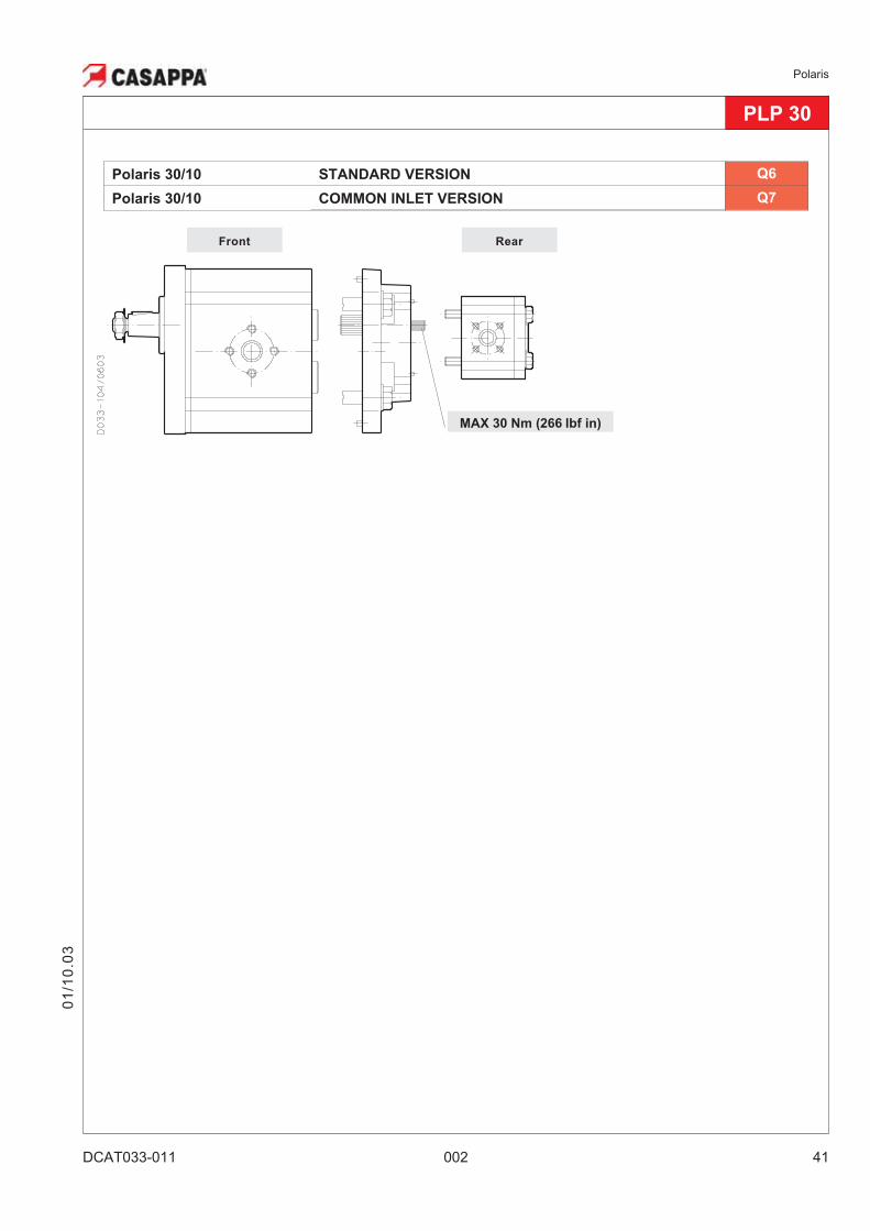
PLP 30
RearFront
Polaris 30/10 STANDARD VERSION Q6
Polaris 30/10 COMMON INLET VERSION Q7
MAX 30 Nm (266 lbf in)
01
/10
.03
Polaris
42 002 DCAT033-011
01
/10
.03
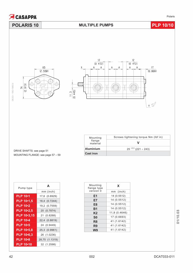
MULTIPLE PUMPSPOLARIS 10 PLP 10/10
DRIVE SHAFTS: see page 51
MOUNTING FLANGE: see page 57 � 59
Pump typeA
mm (inch)
PLP 10•1 17,6 (0.6929)
PLP 10•1,5 18,4 (0.7244)
PLP 10•2 19,2 (0.7559)
PLP 10•2,5 20 (0.7874)
PLP 10•3,15 21 (0.8268)
PLP 10•4 22,4 (0.8819)
PLP 10•5 24 (0.9449)
PLP 10•5,8 25,3 (0.9961)
PLP 10•6,3 26 (1.0236)
PLP 10•8 28,75 (1.1319)
PLP 10•10 32 (1.2598)
Mountingflange
material
Screws tightening torque Nm (lbf in)
V
Aluminium 25+2,5
(221 � 243)
Cast iron
Mountingflange typeversion 0
X
mm (inch)
E1 14 (0.5512)
E7 14 (0.5512)
E8 14 (0.5512)
B1 14 (0.5512)
K2 11,8 (0.4646)
S0 17 (0.6693)
R8 41 (1.6142)
R9 41 (1.6142)
W9 41 (1.6142)
Polaris
DCAT033-011 002 43
01
/10
.03
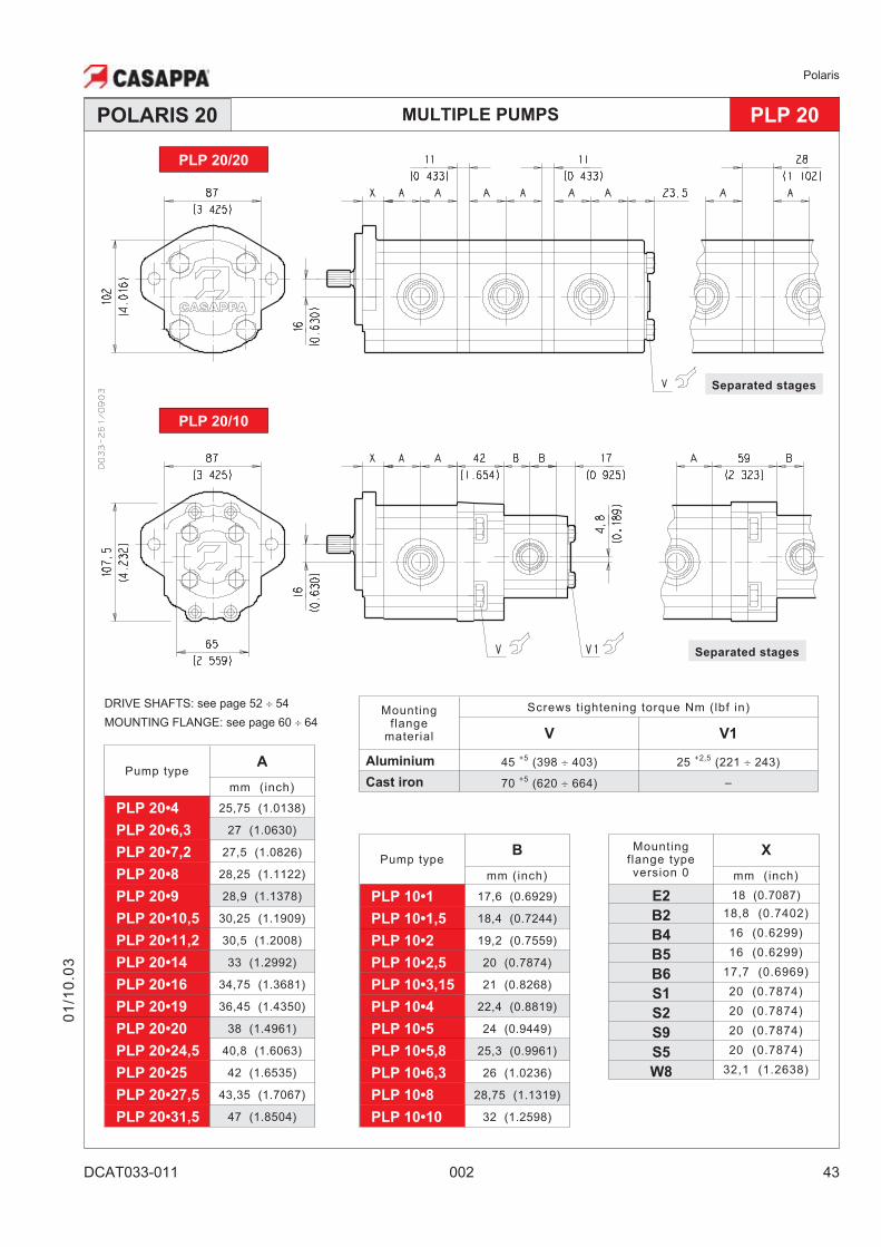
MULTIPLE PUMPS PLP 20POLARIS 20
Separated stages
Separated stages
PLP 20/20
PLP 20/10
Mountingflange typeversion 0
X
mm (inch)
E2 18 (0.7087)
B2 18,8 (0.7402)
B4 16 (0.6299)
B5 16 (0.6299)
B6 17,7 (0.6969)
S1 20 (0.7874)
S2 20 (0.7874)
S9 20 (0.7874)
S5 20 (0.7874)
W8 32,1 (1.2638)
Pump typeB
mm (inch)
PLP 10•1 17,6 (0.6929)
PLP 10•1,5 18,4 (0.7244)
PLP 10•2 19,2 (0.7559)
PLP 10•2,5 20 (0.7874)
PLP 10•3,15 21 (0.8268)
PLP 10•4 22,4 (0.8819)
PLP 10•5 24 (0.9449)
PLP 10•5,8 25,3 (0.9961)
PLP 10•6,3 26 (1.0236)
PLP 10•8 28,75 (1.1319)
PLP 10•10 32 (1.2598)
Pump typeA
mm (inch)
PLP 20•4 25,75 (1.0138)
PLP 20•6,3 27 (1.0630)
PLP 20•7,2 27,5 (1.0826)
PLP 20•8 28,25 (1.1122)
PLP 20•9 28,9 (1.1378)
PLP 20•10,5 30,25 (1.1909)
PLP 20•11,2 30,5 (1.2008)
PLP 20•14 33 (1.2992)
PLP 20•16 34,75 (1.3681)
PLP 20•19 36,45 (1.4350)
PLP 20•20 38 (1.4961)
PLP 20•24,5 40,8 (1.6063)
PLP 20•25 42 (1.6535)
PLP 20•27,5 43,35 (1.7067)
PLP 20•31,5 47 (1.8504)
Mountingflange
material
Screws tightening torque Nm (lbf in)
V V1
Aluminium 45+5
(398 � 403) 25+2,5
(221 � 243)
Cast iron 70+5
(620 � 664) –
DRIVE SHAFTS: see page 52 � 54
MOUNTING FLANGE: see page 60 � 64
Polaris
44 002 DCAT033-011
01
/10
.03
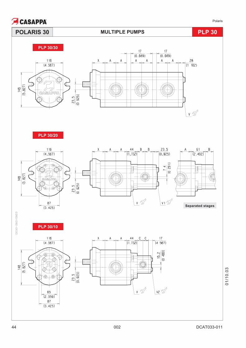
MULTIPLE PUMPS PLP 30POLARIS 30
PLP 30/10
PLP 30/30
PLP 30/20
Separated stages
Polaris
DCAT033-011 002 45
01
/10
.03
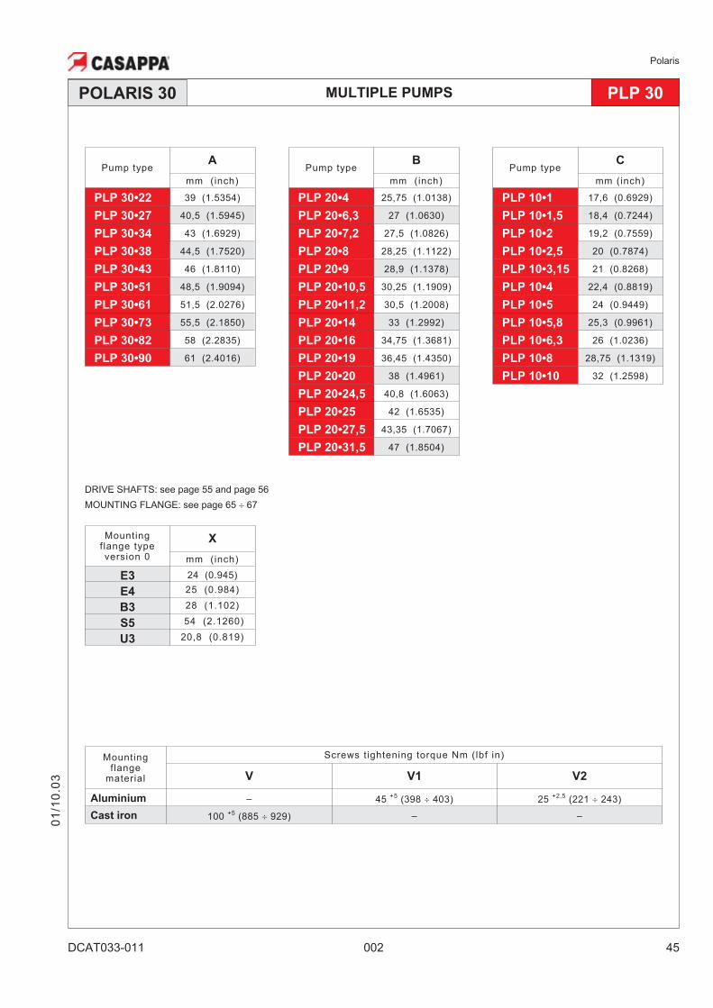
MULTIPLE PUMPS PLP 30POLARIS 30
Pump typeC
mm (inch)
PLP 10•1 17,6 (0.6929)
PLP 10•1,5 18,4 (0.7244)
PLP 10•2 19,2 (0.7559)
PLP 10•2,5 20 (0.7874)
PLP 10•3,15 21 (0.8268)
PLP 10•4 22,4 (0.8819)
PLP 10•5 24 (0.9449)
PLP 10•5,8 25,3 (0.9961)
PLP 10•6,3 26 (1.0236)
PLP 10•8 28,75 (1.1319)
PLP 10•10 32 (1.2598)
Pump typeB
mm (inch)
PLP 20•4 25,75 (1.0138)
PLP 20•6,3 27 (1.0630)
PLP 20•7,2 27,5 (1.0826)
PLP 20•8 28,25 (1.1122)
PLP 20•9 28,9 (1.1378)
PLP 20•10,5 30,25 (1.1909)
PLP 20•11,2 30,5 (1.2008)
PLP 20•14 33 (1.2992)
PLP 20•16 34,75 (1.3681)
PLP 20•19 36,45 (1.4350)
PLP 20•20 38 (1.4961)
PLP 20•24,5 40,8 (1.6063)
PLP 20•25 42 (1.6535)
PLP 20•27,5 43,35 (1.7067)
PLP 20•31,5 47 (1.8504)
Pump typeA
mm (inch)
PLP 30•22 39 (1.5354)
PLP 30•27 40,5 (1.5945)
PLP 30•34 43 (1.6929)
PLP 30•38 44,5 (1.7520)
PLP 30•43 46 (1.8110)
PLP 30•51 48,5 (1.9094)
PLP 30•61 51,5 (2.0276)
PLP 30•73 55,5 (2.1850)
PLP 30•82 58 (2.2835)
PLP 30•90 61 (2.4016)
Mountingflange typeversion 0
X
mm (inch)
E3 24 (0.945)
E4 25 (0.984)
B3 28 (1.102)
S5 54 (2.1260)
U3 20,8 (0.819)
Mountingflange
material
Screws tightening torque Nm (lbf in)
V V1 V2
Aluminium – 45+5
(398 � 403) 25+2,5
(221 � 243)
Cast iron 100+5
(885 � 929) – –
DRIVE SHAFTS: see page 55 and page 56
MOUNTING FLANGE: see page 65 � 67
Polaris
46 002 DCAT033-012
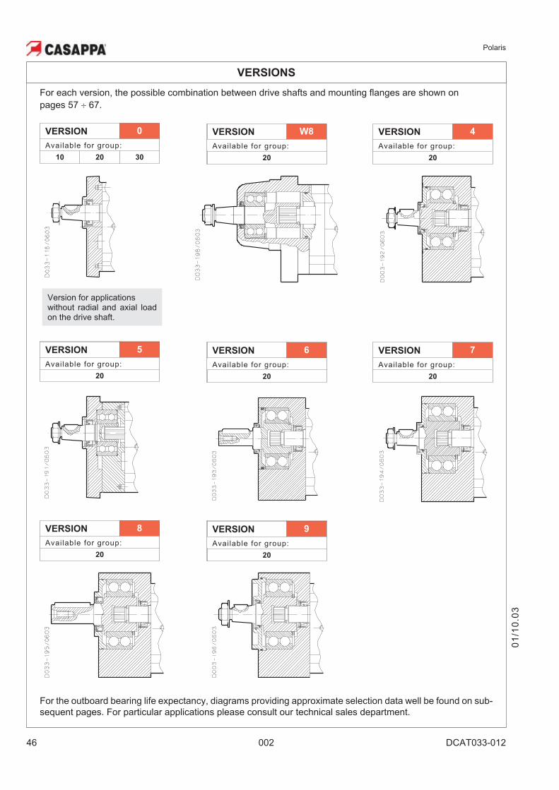
VERSIONS
For each version, the possible combination between drive shafts and mounting flanges are shown on
pages 57 � 67.
VERSION 7
Available for group:
20
VERSION 5
Available for group:
20
VERSION 6
Available for group:
20
VERSION 8
Available for group:
20
VERSION 9
Available for group:
20
Version for applicationswithout radial and axial loadon the drive shaft.
VERSION 0
Available for group:
10 20 30
VERSION 4
Available for group:
20
VERSION W8
Available for group:
20
01
/10
.03
For the outboard bearing life expectancy, diagrams providing approximate selection data well be found on sub-
sequent pages. For particular applications please consult our technical sales department.
Polaris
DCAT033-012 002 47
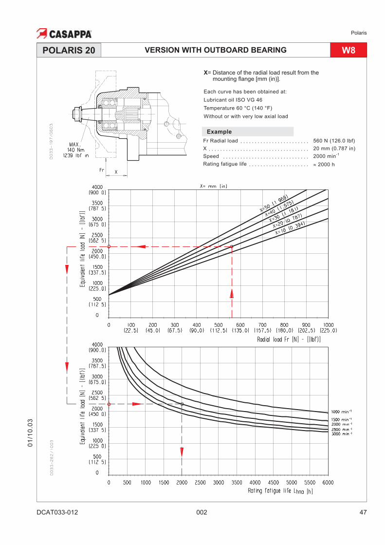
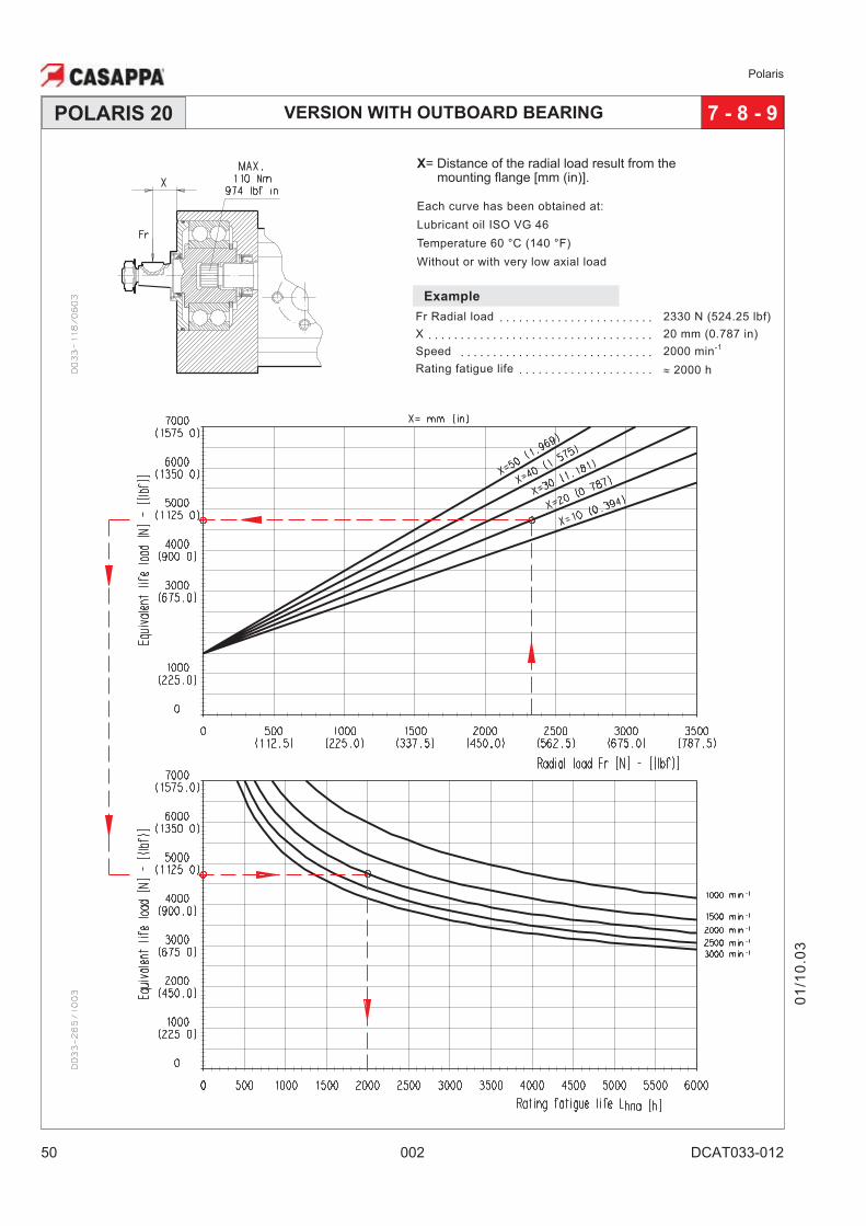
VERSION WITH OUTBOARD BEARINGPOLARIS 20
X= Distance of the radial load result from themounting flange [mm (in)].
Each curve has been obtained at:
Lubricant oil ISO VG 46
Temperature 60 °C (140 °F)
Without or with very low axial load
Example
Fr Radial load · · · · · · · · · · · · · · · · · · · · · · · · 560 N (126.0 lbf)
X · · · · · · · · · · · · · · · · · · · · · · · · · · · · · · · · · · · 20 mm (0.787 in)
Speed · · · · · · · · · · · · · · · · · · · · · · · · · · · · · · 2000 min-1
Rating fatigue life · · · · · · · · · · · · · · · · · · · · · � 2000 h
W8
01
/10
.03
Polaris
48 002 DCAT033-012
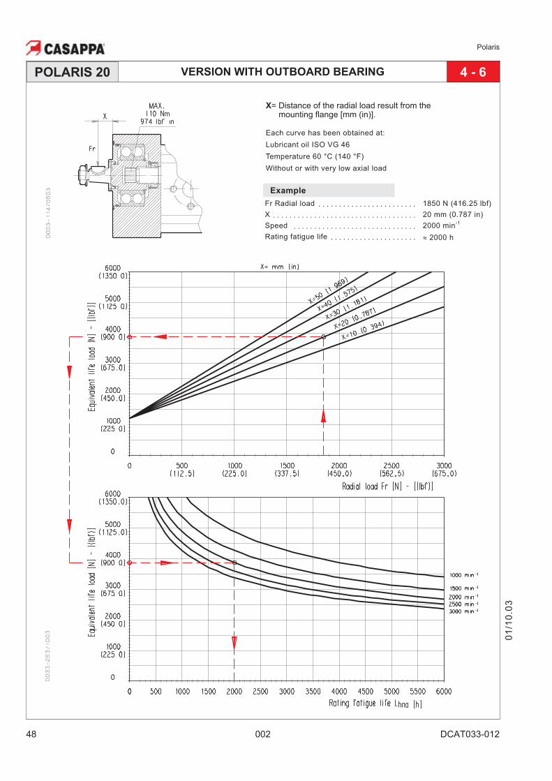
VERSION WITH OUTBOARD BEARINGPOLARIS 20
Example
Fr Radial load · · · · · · · · · · · · · · · · · · · · · · · · 1850 N (416.25 lbf)
X · · · · · · · · · · · · · · · · · · · · · · · · · · · · · · · · · · · 20 mm (0.787 in)
Speed · · · · · · · · · · · · · · · · · · · · · · · · · · · · · · 2000 min-1
Rating fatigue life · · · · · · · · · · · · · · · · · · · · · � 2000 h
4 - 6
X= Distance of the radial load result from themounting flange [mm (in)].
Each curve has been obtained at:
Lubricant oil ISO VG 46
Temperature 60 °C (140 °F)
Without or with very low axial load
01
/10
.03
Polaris
DCAT033-012 002 49
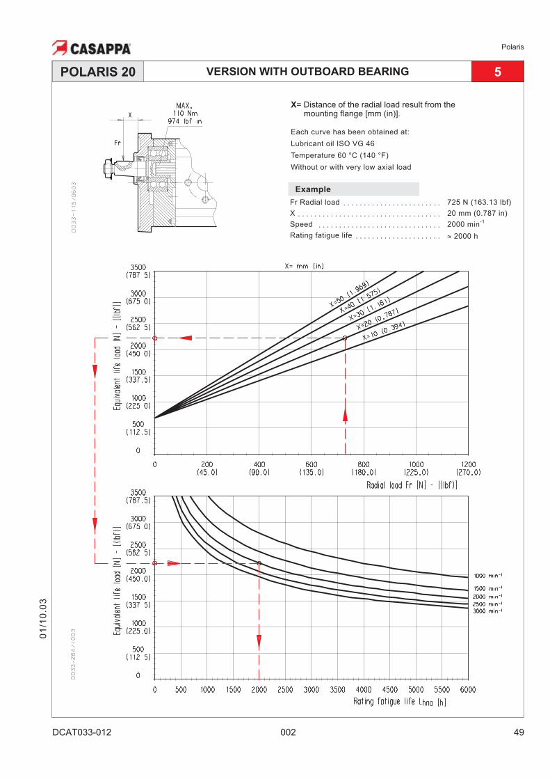
VERSION WITH OUTBOARD BEARINGPOLARIS 20
Example
Fr Radial load · · · · · · · · · · · · · · · · · · · · · · · · 725 N (163.13 lbf)
X · · · · · · · · · · · · · · · · · · · · · · · · · · · · · · · · · · · 20 mm (0.787 in)
Speed · · · · · · · · · · · · · · · · · · · · · · · · · · · · · · 2000 min-1
Rating fatigue life · · · · · · · · · · · · · · · · · · · · · � 2000 h
5
X= Distance of the radial load result from themounting flange [mm (in)].
Each curve has been obtained at:
Lubricant oil ISO VG 46
Temperature 60 °C (140 °F)
Without or with very low axial load
01
/10
.03
Polaris
50 002 DCAT033-012
VERSION WITH OUTBOARD BEARINGPOLARIS 20
Example
Fr Radial load · · · · · · · · · · · · · · · · · · · · · · · · 2330 N (524.25 lbf)
X · · · · · · · · · · · · · · · · · · · · · · · · · · · · · · · · · · · 20 mm (0.787 in)
Speed · · · · · · · · · · · · · · · · · · · · · · · · · · · · · · 2000 min-1
Rating fatigue life · · · · · · · · · · · · · · · · · · · · · � 2000 h
7 - 8 - 9
01
/10
.03
X= Distance of the radial load result from themounting flange [mm (in)].
Each curve has been obtained at:
Lubricant oil ISO VG 46
Temperature 60 °C (140 °F)
Without or with very low axial load
Polaris
DCAT033-013 002 51
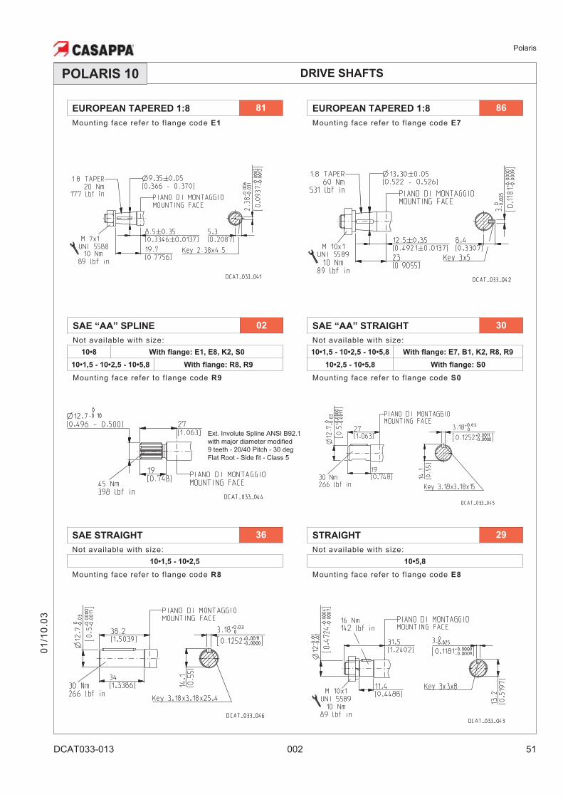
DRIVE SHAFTSPOLARIS 10
EUROPEAN TAPERED 1:8 86
Mounting face refer to flange code E7
01
/10
.03
EUROPEAN TAPERED 1:8 81
Mounting face refer to flange code E1
Ext. Involute Spline ANSI B92.1
with major diameter modified
9 teeth - 20/40 Pitch - 30 deg
Flat Root - Side fit - Class 5
SAE “AA” SPLINE 02
Not available with size:
10•8 With flange: E1, E8, K2, S0
10•1,5 - 10•2,5 - 10•5,8 With flange: R8, R9
Mounting face refer to flange code R9
STRAIGHT 29
Not available with size:
10•5,8
Mounting face refer to flange code E8
SAE “AA” STRAIGHT 30
Not available with size:
10•1,5 - 10•2,5 - 10•5,8 With flange: E7, B1, K2, R8, R9
10•2,5 - 10•5,8 With flange: S0
Mounting face refer to flange code S0
SAE STRAIGHT 36
Not available with size:
10•1,5 - 10•2,5
Mounting face refer to flange code R8
Polaris
52 002 DCAT033-013
DRIVE SHAFTS
01
/10
.03
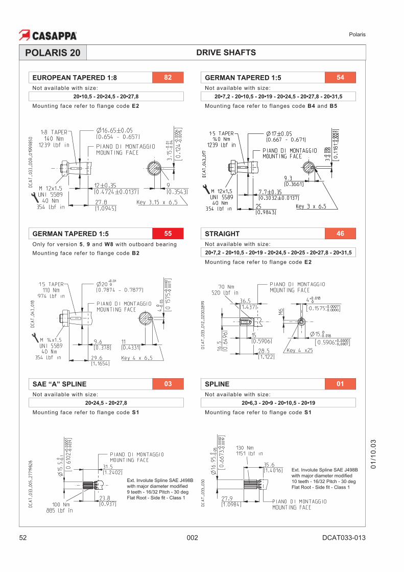
POLARIS 20
GERMAN TAPERED 1:5 55
Only for version 5, 9 and W8 with outboard bearing
Mounting face refer to flange code B2
Ext. Involute Spline SAE J498B
with major diameter modified
9 teeth - 16/32 Pitch - 30 deg
Flat Root - Side fit - Class 1
Ext. Involute Spline SAE J498B
with major diameter modified
10 teeth - 16/32 Pitch - 30 deg
Flat Root - Side fit - Class 1
EUROPEAN TAPERED 1:8 82
Not available with size:
20•10,5 - 20•24,5 - 20•27,8
Mounting face refer to flange code E2
GERMAN TAPERED 1:5 54
Not available with size:
20•7,2 - 20•10,5 - 20•19 - 20•24,5 - 20•27,8 - 20•31,5
Mounting face refer to flanges code B4 and B5
STRAIGHT 46
Not available with size:
20•7,2 - 20•10,5 - 20•19 - 20•24,5 - 20•25 - 20•27,8 - 20•31,5
Mounting face refer to flange code E2
SAE “A” SPLINE 03
Not available with size:
20•24,5 - 20•27,8
Mounting face refer to flange code S1
SPLINE 01
Not available with size:
20•6,3 - 20•9 - 20•10,5 - 20•19
Mounting face refer to flange code S1
Polaris
DCAT033-013 002 53
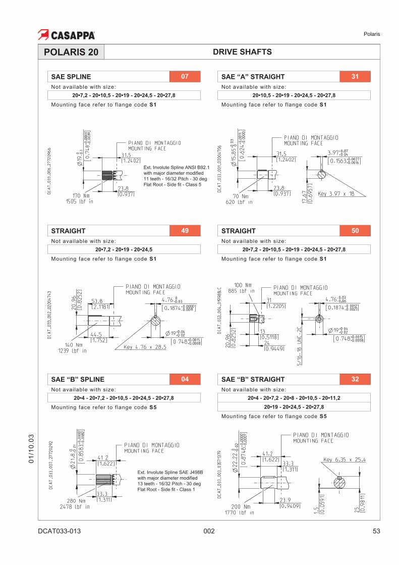
DRIVE SHAFTSPOLARIS 20
01
/10
.03
Ext. Involute Spline ANSI B92.1
with major diameter modified
11 teeth - 16/32 Pitch - 30 deg
Flat Root - Side fit - Class 5
Ext. Involute Spline SAE J498B
with major diameter modified
13 teeth - 16/32 Pitch - 30 deg
Flat Root - Side fit - Class 1
SAE SPLINE 07
Not available with size:
20•7,2 - 20•10,5 - 20•19 - 20•24,5 - 20•27,8
Mounting face refer to flange code S1
SAE “A” STRAIGHT 31
Not available with size:
20•10,5 - 20•19 - 20•24,5 - 20•27,8
Mounting face refer to flange code S1
STRAIGHT 49
Not available with size:
20•7,2 - 20•19 - 20•24,5
Mounting face refer to flange code S1
STRAIGHT 50
Not available with size:
20•7,2 - 20•10,5 - 20•19 - 20•24,5 - 20•27,8
Mounting face refer to flange code S1
SAE “B” SPLINE 04
Not available with size:
20•4 - 20•7,2 - 20•10,5 - 20•24,5 - 20•27,8
Mounting face refer to flange code S5
SAE “B” STRAIGHT 32
Not available with size:
20•4 - 20•7,2 - 20•8 - 20•10,5 - 20•11,2
20•19 - 20•24,5 - 20•27,8
Mounting face refer to flange code S5
Polaris
54 002 DCAT033-013
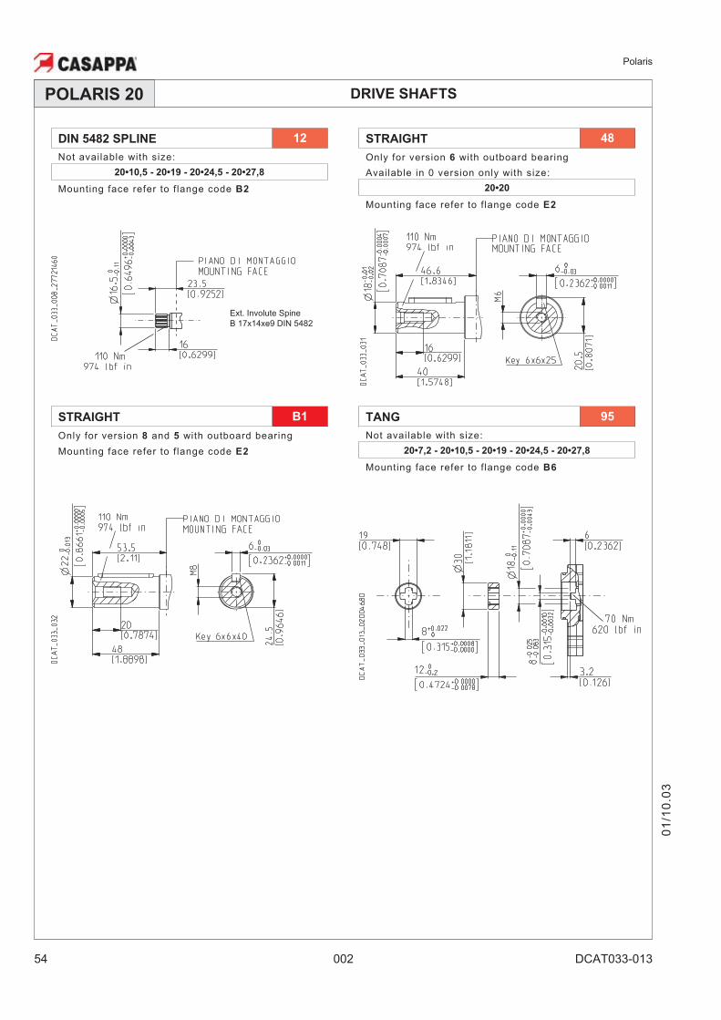
DRIVE SHAFTSPOLARIS 20
01
/10
.03
Ext. Involute Spine
B 17x14xe9 DIN 5482
DIN 5482 SPLINE 12
Not available with size:
20•10,5 - 20•19 - 20•24,5 - 20•27,8
Mounting face refer to flange code B2
STRAIGHT 48
Only for version 6 with outboard bearing
Available in 0 version only with size:
20•20
Mounting face refer to flange code E2
STRAIGHT B1
Only for version 8 and 5 with outboard bearing
Mounting face refer to flange code E2
TANG 95
Not available with size:
20•7,2 - 20•10,5 - 20•19 - 20•24,5 - 20•27,8
Mounting face refer to flange code B6
Polaris
DCAT033-013 002 55
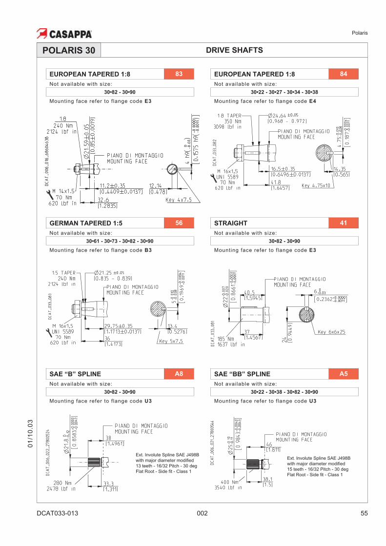
DRIVE SHAFTSPOLARIS 30
01
/10
.03
Ext. Involute Spline SAE J498B
with major diameter modified
13 teeth - 16/32 Pitch - 30 deg
Flat Root - Side fit - Class 1
Ext. Involute Spline SAE J498B
with major diameter modified
15 teeth - 16/32 Pitch - 30 deg
Flat Root - Side fit - Class 1
EUROPEAN TAPERED 1:8 83
Not available with size:
30•82 - 30•90
Mounting face refer to flange code E3
EUROPEAN TAPERED 1:8 84
Not available with size:
30•22 - 30•27 - 30•34 - 30•38
Mounting face refer to flange code E4
GERMAN TAPERED 1:5 56
Not available with size:
30•61 - 30•73 - 30•82 - 30•90
Mounting face refer to flange code B3
STRAIGHT 41
Not available with size:
30•82 - 30•90
Mounting face refer to flange code E3
SAE “B” SPLINE A8
Not available with size:
30•82 - 30•90
Mounting face refer to flange code U3
SAE “BB” SPLINE A5
Not available with size:
30•22 - 30•38 - 30•82 - 30•90
Mounting face refer to flange code U3
Polaris
56 002 DCAT033-013
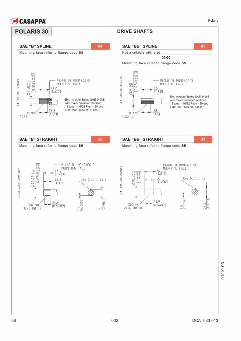
DRIVE SHAFTSPOLARIS 30
Ext. Involute Spline SAE J498B
with major diameter modified
15 teeth - 16/32 Pitch - 30 deg
Flat Root - Side fit - Class 1
SAE “B” STRAIGHT 32
Mounting face refer to flange code S5
SAE “BB” STRAIGHT 33
Mounting face refer to flange code S5
Ext. Involute Spline SAE J498B
with major diameter modified
13 teeth - 16/32 Pitch - 30 deg
Flat Root - Side fit - Class 1
01
/10
.03
SAE “B” SPLINE 04
Mounting face refer to flange code S5
SAE “BB” SPLINE 05
Not available with size:
30•90
Mounting face refer to flange code S5
Polaris
DCAT033-014 002 57
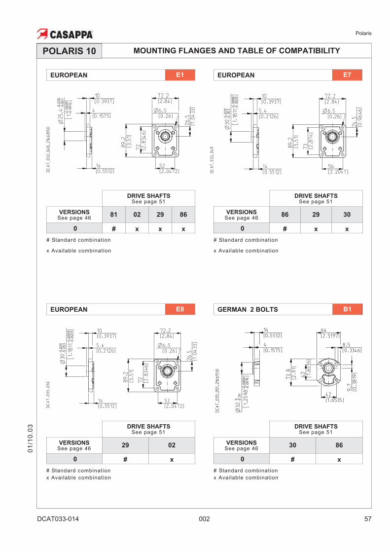
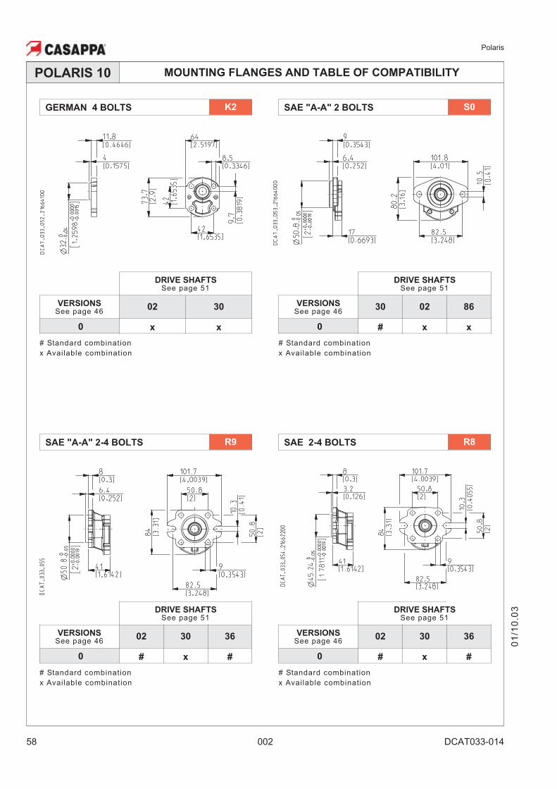
MOUNTING FLANGES AND TABLE OF COMPATIBILITYPOLARIS 10
01
/10
.03
DRIVE SHAFTSSee page 51
VERSIONSSee page 46
86 29 30
0 # x x
# Standard combination
x Available combination
DRIVE SHAFTSSee page 51
VERSIONSSee page 46
81 02 29 86
0 # x x x
# Standard combination
x Available combination
GERMAN 2 BOLTS B1EUROPEAN E8
DRIVE SHAFTSSee page 51
VERSIONSSee page 46
30 86
0 # x
# Standard combination
x Available combination
EUROPEAN E7EUROPEAN E1
DRIVE SHAFTSSee page 51
VERSIONSSee page 46
29 02
0 # x
# Standard combination
x Available combination
Polaris
58 002 DCAT033-014
MOUNTING FLANGES AND TABLE OF COMPATIBILITY
01
/10
.03
SAE "A-A" 2 BOLTS S0
SAE 2-4 BOLTS R8
GERMAN 4 BOLTS K2
SAE "A-A" 2-4 BOLTS R9
DRIVE SHAFTSSee page 51
VERSIONSSee page 46
30 02 86
0 # x x
# Standard combination
x Available combination
POLARIS 10
DRIVE SHAFTSSee page 51
VERSIONSSee page 46
02 30
0 x x
# Standard combination
x Available combination
DRIVE SHAFTSSee page 51
VERSIONSSee page 46
02 30 36
0 # x #
# Standard combination
x Available combination
DRIVE SHAFTSSee page 51
VERSIONSSee page 46
02 30 36
0 # x #
# Standard combination
x Available combination
Polaris
DCAT033-014 002 59
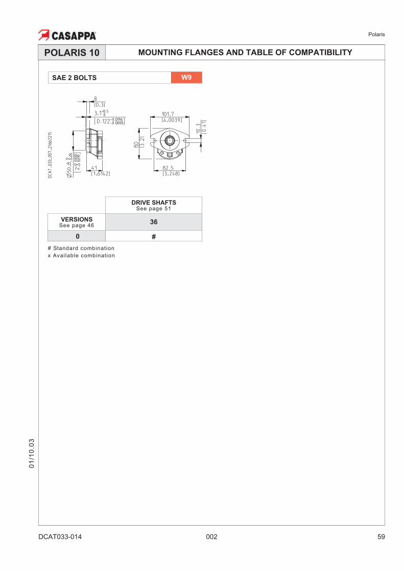
MOUNTING FLANGES AND TABLE OF COMPATIBILITY
SAE 2 BOLTS W9
DRIVE SHAFTSSee page 51
VERSIONSSee page 46
36
0 #
# Standard combination
x Available combination
POLARIS 10
01
/10
.03
Polaris
60 002 DCAT033-014
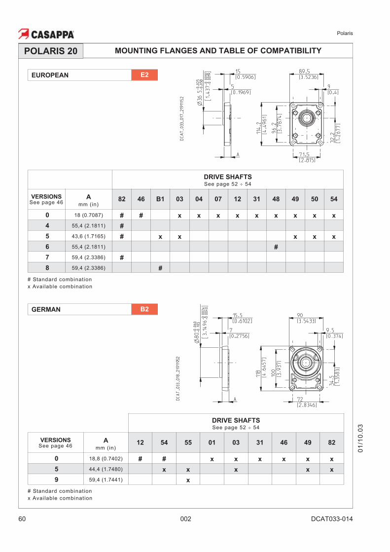
MOUNTING FLANGES AND TABLE OF COMPATIBILITYPOLARIS 20
GERMAN B2
DRIVE SHAFTS
See page 52 � 54
VERSIONSSee page 46
A
mm (in)12 54 55 01 03 31 46 49 82
0 18,8 (0.7402) # # x x x x x x
5 44,4 (1.7480) x x x x x
9 59,4 (1.7441) x
# Standard combination
x Available combination
EUROPEAN E2
DRIVE SHAFTS
See page 52 � 54
VERSIONSSee page 46
A
mm (in)82 46 B1 03 04 07 12 31 48 49 50 54
0 18 (0.7087) # # x x x x x x x x x
4 55,4 (2.1811) #
5 43,6 (1.7165) # x x x x x
6 55,4 (2.1811) #
7 59,4 (2.3386) #
8 59,4 (2.3386) #
# Standard combination
x Available combination
01
/10
.03
Polaris
DCAT033-014 002 61
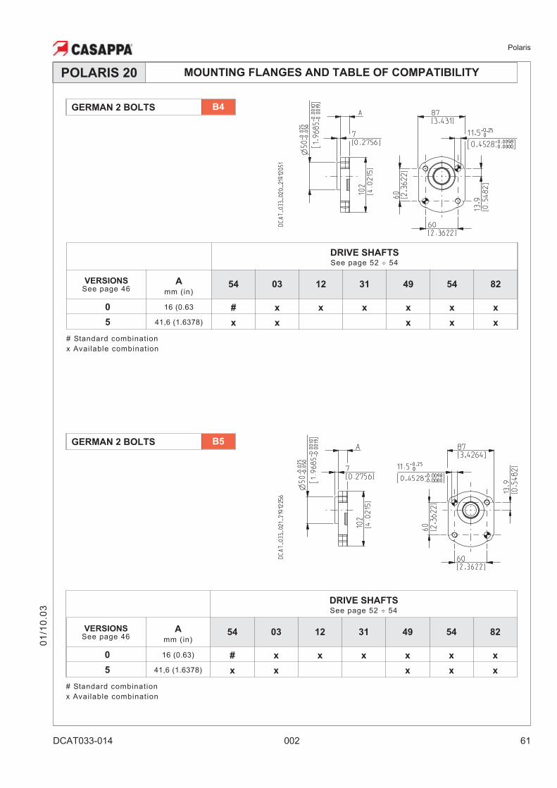
MOUNTING FLANGES AND TABLE OF COMPATIBILITYPOLARIS 20
01
/10
.03
GERMAN 2 BOLTS B5
GERMAN 2 BOLTS B4
DRIVE SHAFTS
See page 52 � 54
VERSIONSSee page 46
A
mm (in)54 03 12 31 49 54 82
0 16 (0.63) # x x x x x x
5 41,6 (1.6378) x x x x x
# Standard combination
x Available combination
DRIVE SHAFTS
See page 52 � 54
VERSIONSSee page 46
A
mm (in)54 03 12 31 49 54 82
0 16 (0.63 # x x x x x x
5 41,6 (1.6378) x x x x x
# Standard combination
x Available combination
Polaris
62 002 DCAT033-014
MOUNTING FLANGES AND TABLE OF COMPATIBILITYPOLARIS 20
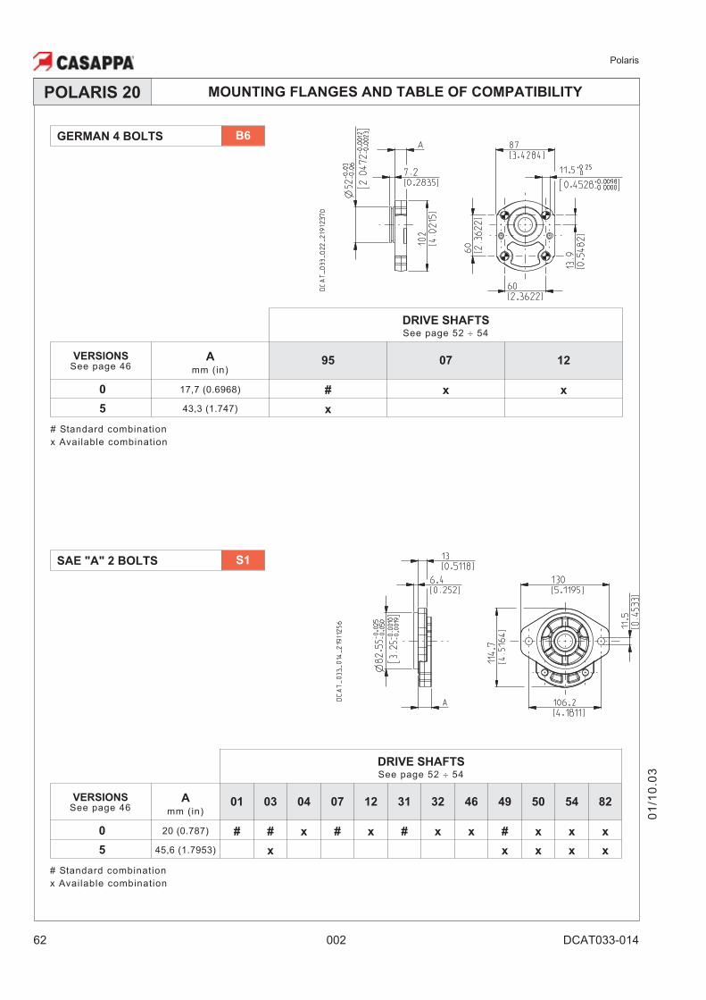
SAE "A" 2 BOLTS S1
DRIVE SHAFTS
See page 52 � 54
VERSIONSSee page 46
A
mm (in)01 03 04 07 12 31 32 46 49 50 54 82
0 20 (0.787) # # x # x # x x # x x x
5 45,6 (1.7953) x x x x x
# Standard combination
x Available combination
GERMAN 4 BOLTS B6
DRIVE SHAFTS
See page 52 � 54
VERSIONSSee page 46
A
mm (in)95 07 12
0 17,7 (0.6968) # x x
5 43,3 (1.747) x
# Standard combination
x Available combination
01
/10
.03
Polaris
DCAT033-014 002 63
MOUNTING FLANGES AND TABLE OF COMPATIBILITYPOLARIS 20
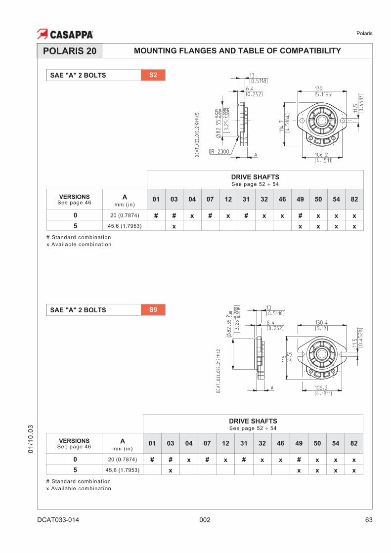
SAE "A" 2 BOLTS S2
01
/10
.03
SAE "A" 2 BOLTS S9
DRIVE SHAFTS
See page 52 � 54
VERSIONSSee page 46
A
mm (in)01 03 04 07 12 31 32 46 49 50 54 82
0 20 (0.7874) # # x # x # x x # x x x
5 45,6 (1.7953) x x x x x
# Standard combination
x Available combination
DRIVE SHAFTS
See page 52 � 54
VERSIONSSee page 46
A
mm (in)01 03 04 07 12 31 32 46 49 50 54 82
0 20 (0.7874) # # x # x # x x # x x x
5 45,6 (1.7953) x x x x x
# Standard combination
x Available combination
Polaris
64 002 DCAT033-014
MOUNTING FLANGES AND TABLE OF COMPATIBILITYPOLARIS 20
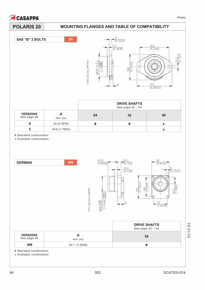
SAE "B" 2 BOLTS S5
01
/10
.03
GERMAN W8
DRIVE SHAFTS
See page 52 � 54
VERSIONSSee page 46
A
mm (in)55
W8 32,1 (1.2638) #
# Standard combination
x Available combination
DRIVE SHAFTS
See page 52 � 54
VERSIONSSee page 46
A
mm (in)04 32 49
0 20 (0.7874) # # x
5 45,6 (1.7953) x
# Standard combination
x Available combination
Polaris
DCAT033-014 002 65
MOUNTING FLANGES AND TABLE OF COMPATIBILITYPOLARIS 30
01
/10
.03
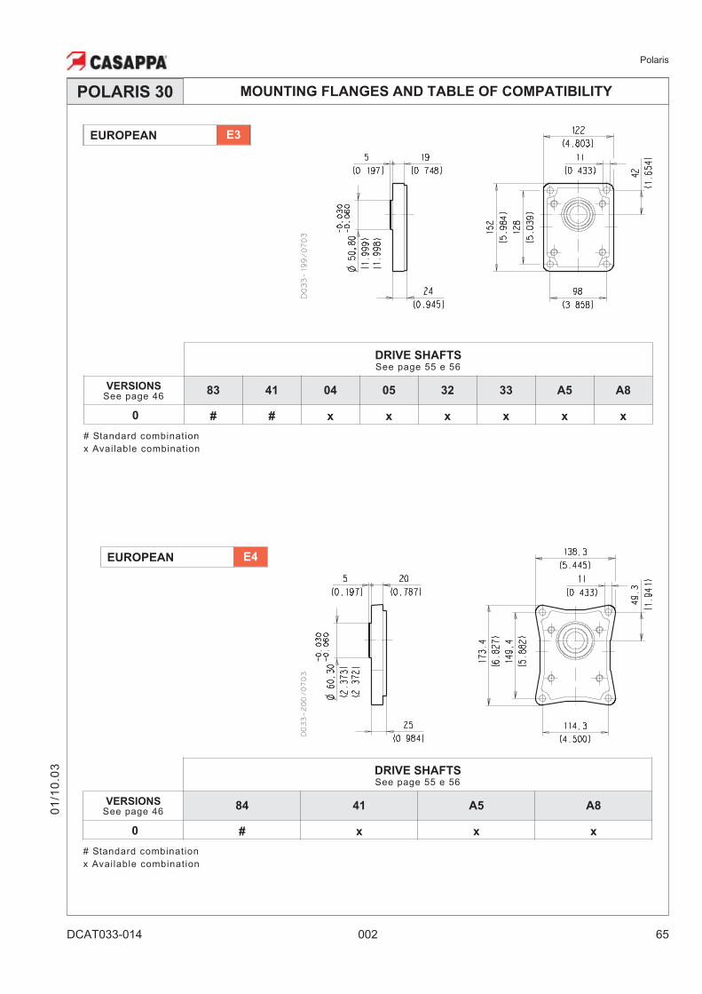
EUROPEAN E4
DRIVE SHAFTSSee page 55 e 56
VERSIONSSee page 46
84 41 A5 A8
0 # x x x
# Standard combination
x Available combination
EUROPEAN E3
DRIVE SHAFTSSee page 55 e 56
VERSIONSSee page 46
83 41 04 05 32 33 A5 A8
0 # # x x x x x x
# Standard combination
x Available combination
Polaris
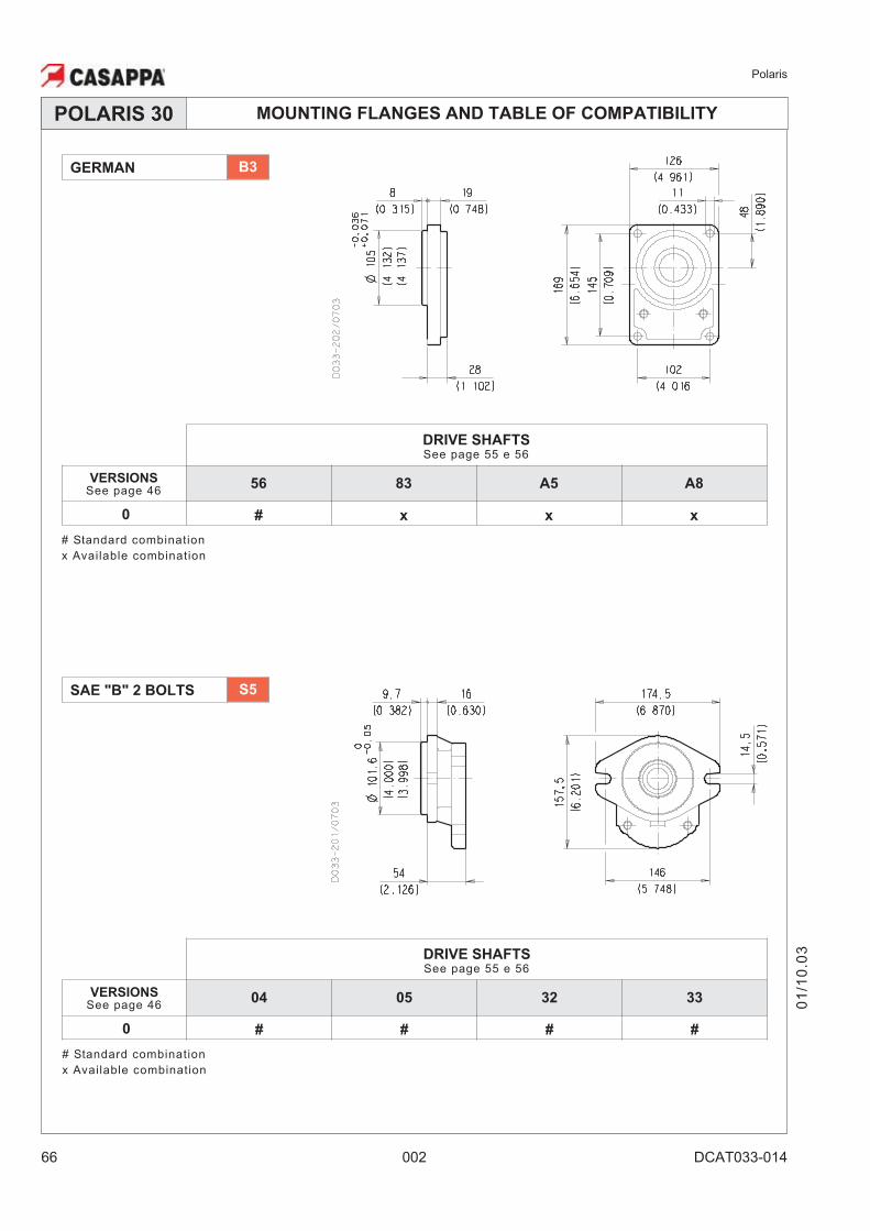
66 002 DCAT033-014
MOUNTING FLANGES AND TABLE OF COMPATIBILITYPOLARIS 30
01
/10
.03
SAE "B" 2 BOLTS S5
DRIVE SHAFTSSee page 55 e 56
VERSIONSSee page 46
56 83 A5 A8
0 # x x x
# Standard combination
x Available combination
GERMAN B3
DRIVE SHAFTSSee page 55 e 56
VERSIONSSee page 46
04 05 32 33
0 # # # #
# Standard combination
x Available combination
Polaris
DCAT033-014 002 67
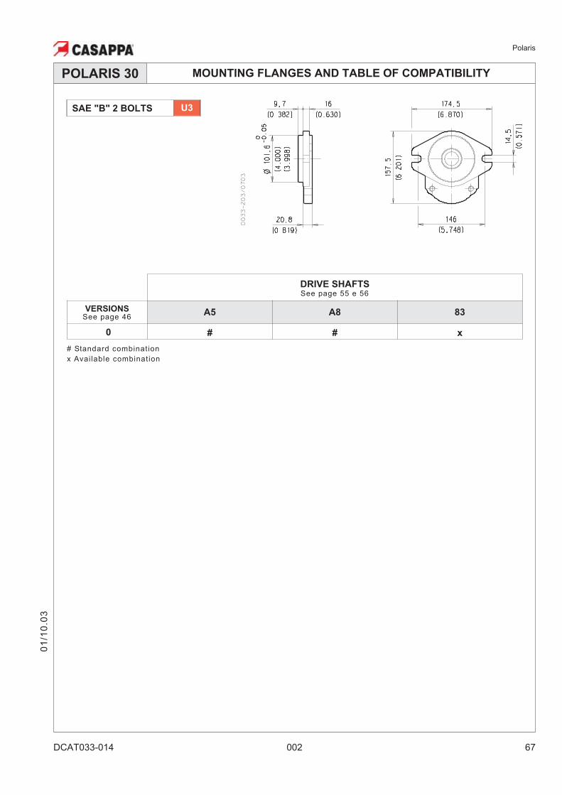
MOUNTING FLANGES AND TABLE OF COMPATIBILITYPOLARIS 30
01
/10
.03
DRIVE SHAFTSSee page 55 e 56
VERSIONSSee page 46
A5 A8 83
0 # # x
# Standard combination
x Available combination
SAE "B" 2 BOLTS U3
Polaris
68 002 DCAT033-015
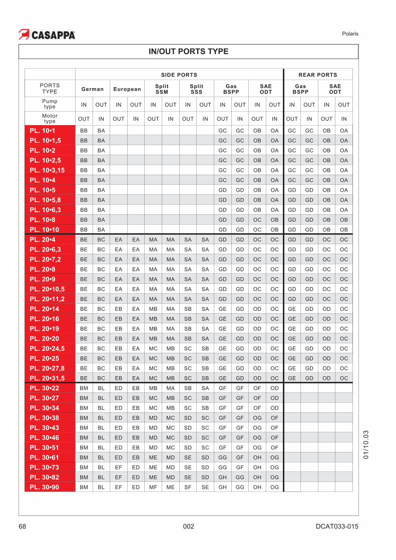
SIDE PORTS REAR PORTS
PORTSTYPE
German EuropeanSplit
SSM
Split
SSS
Gas
BSPP
SAE
ODT
Gas
BSPP
SAE
ODT
Pumptype IN OUT IN OUT IN OUT IN OUT IN OUT IN OUT IN OUT IN OUT
Motortype OUT IN OUT IN OUT IN OUT IN OUT IN OUT IN OUT IN OUT IN
PL. 10•1 BB BA GC GC OB OA GC GC OB OA
PL. 10•1,5 BB BA GC GC OB OA GC GC OB OA
PL. 10•2 BB BA GC GC OB OA GC GC OB OA
PL. 10•2,5 BB BA GC GC OB OA GC GC OB OA
PL. 10•3,15 BB BA GC GC OB OA GC GC OB OA
PL. 10•4 BB BA GC GC OB OA GC GC OB OA
PL. 10•5 BB BA GD GD OB OA GD GD OB OA
PL. 10•5,8 BB BA GD GD OB OA GD GD OB OA
PL. 10•6,3 BB BA GD GD OB OA GD GD OB OA
PL. 10•8 BB BA GD GD OC OB GD GD OB OB
PL. 10•10 BB BA GD GD OC OB GD GD OB OB
PL. 20•4 BE BC EA EA MA MA SA SA GD GD OC OC GD GD OC OC
PL. 20•6,3 BE BC EA EA MA MA SA SA GD GD OC OC GD GD OC OC
PL. 20•7,2 BE BC EA EA MA MA SA SA GD GD OC OC GD GD OC OC
PL. 20•8 BE BC EA EA MA MA SA SA GD GD OC OC GD GD OC OC
PL. 20•9 BE BC EA EA MA MA SA SA GD GD OC OC GD GD OC OC
PL. 20•10,5 BE BC EA EA MA MA SA SA GD GD OC OC GD GD OC OC
PL. 20•11,2 BE BC EA EA MA MA SA SA GD GD OC OC GD GD OC OC
PL. 20•14 BE BC EB EA MB MA SB SA GE GD OD OC GE GD OD OC
PL. 20•16 BE BC EB EA MB MA SB SA GE GD OD OC GE GD OD OC
PL. 20•19 BE BC EB EA MB MA SB SA GE GD OD OC GE GD OD OC
PL. 20•20 BE BC EB EA MB MA SB SA GE GD OD OC GE GD OD OC
PL. 20•24,5 BE BC EB EA MC MB SC SB GE GD OD OC GE GD OD OC
PL. 20•25 BE BC EB EA MC MB SC SB GE GD OD OC GE GD OD OC
PL. 20•27,8 BE BC EB EA MC MB SC SB GE GD OD OC GE GD OD OC
PL. 20•31,5 BE BC EB EA MC MB SC SB GE GD OD OC GE GD OD OC
PL. 30•22 BM BL ED EB MB MA SB SA GF GF OF OD
PL. 30•27 BM BL ED EB MC MB SC SB GF GF OF OD
PL. 30•34 BM BL ED EB MC MB SC SB GF GF OF OD
PL. 30•38 BM BL ED EB MD MC SD SC GF GF OG OF
PL. 30•43 BM BL ED EB MD MC SD SC GF GF OG OF
PL. 30•46 BM BL ED EB MD MC SD SC GF GF OG OF
PL. 30•51 BM BL ED EB MD MC SD SC GF GF OG OF
PL. 30•61 BM BL ED EB ME MD SE SD GG GF OH OG
PL. 30•73 BM BL EF ED ME MD SE SD GG GF OH OG
PL. 30•82 BM BL EF ED ME MD SE SD GH GG OH OG
PL. 30•90 BM BL EF ED MF ME SF SE GH GG OH OG
IN/OUT PORTS TYPE
01
/10
.03
Polaris
DCAT033-015 002 69
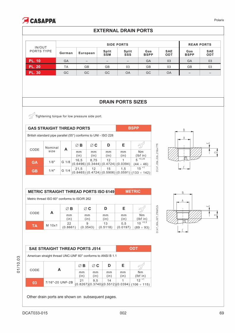
EXTERNAL DRAIN PORTS
IN/OUTPORTS TYPE
SIDE PORTS REAR PORTS
German EuropeanSplit
SSM
Split
SSS
Gas
BSPP
SAE
ODT
Gas
BSPP
SAE
ODT
PL. 10 GA – – – GA 03 GA 03
PL. 20 TA GB GB 03 GB 03 GB 03
PL. 30 GC GC GC OA GC OA – –
01
/10
.03
Tightening torque for low pressure side port.
GAS STRAIGHT THREAD PORTS BSPP
British standard pipe parallel (55°) conforms to UNI - ISO 228
CODENominal
sizeA
� B � C D E
mm(in)
mm(in)
mm(in)
mm(in)
Nm(lbf in)
GA 1/8" G 1/816,5
(0.6496)8,75
(0.3444)12
(0.4724)1
(0.0394)
5+0,25
(44 � 46)
GB 1/4" G 1/421,5
(0.8465)12
(0.4724)15
(0.5906)1,5
(0.0591)
15+1
(133 � 142)
DRAIN PORTS SIZES
SAE STRAIGHT THREAD PORTS J514 ODT
American straight thread UNC-UNF 60° conforms to ANSI B 1.1
CODE A
� B � C D E
mm(in)
mm(in)
mm(in)
mm(in)
Nm(lbf in)
03 7/16"-20 UNF-2B21
(0.8267)9,5
(0.3740)14
(0.5512)1
(0.0394)
12+1
(106 � 115)
METRIC STRAIGHT THREAD PORTS ISO 6149 METRIC
Metric thread ISO 60° conforms to ISO/R 262
CODE A
� B � C D E
mm(in)
mm(in)
mm(in)
mm(in)
Nm(lbf in)
TA M 10x122
(0.8661)9
(0.3543)13
(0.5118)0,5
(0.0197)
10+0,5
(89 � 93)
Other drain ports are shown on subsequent pages.
Polaris
70 002 DCAT033-015
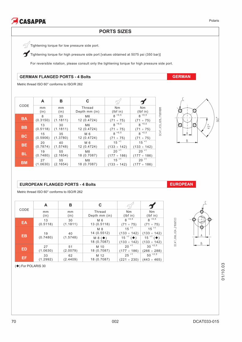
PORTS SIZES
EUROPEAN FLANGED PORTS - 4 Bolts EUROPEAN
Metric thread ISO 60° conforms to ISO/R 262
CODE
A B C
mm(in)
mm(in)
ThreadDepth mm (in)
Nm(lbf in)
Nm(lbf in)
EA13
(0.5118)30
(1.1811)M 6
13 (0.5118)
8+0,5
(71 � 75)
8+0,5
(71 � 75)
EB19
(0.7480)40
(1.5748)
M 814 (0.5512)
15+1
(133 � 142)
15+1
(133 � 142)
M 8 (�)18 (0.7087)
15+1
(�)
(133 � 142)
15+1
(�)
(133 � 142)
ED27
(1.0630)51
(2.0079)M 10
18 (0.7087)
20+1
(177 � 186)
30+2,5
(266 � 288)
EF33
(1.2992)62
(2.4409)M 12
18 (0.7087)
25+1
(221 � 230)
50+2,5
(443 � 465)
(�) For POLARIS 30
01
/10
.03
Tightening torque for low pressure side port.
Tightening torque for high pressure side port [values obtained at 5075 psi (350 bar)]
For reversible rotation, please consult only the tightening torque for high pressure side port.
GERMAN FLANGED PORTS - 4 Bolts GERMAN
Metric thread ISO 60° conforms to ISO/R 262
CODE
A B C
mm(in)
mm(in)
ThreadDepth mm (in)
Nm(lbf in)
Nm(lbf in)
BA8
(0.3150)30
(1.1811)M6
12 (0.4724)
8+0,5
(71 � 75)
8+0,5
(71 � 75)
BB13
(0.5118)30
(1.1811)M6
12 (0.4724)
8+0,5
(71 � 75)
8+0,5
(71 � 75)
BC15
(0.5906)35
(1.3780)M 6
12 (0.4724)
8+0,5
(71 � 75)
8+0,5
(71 � 75)
BE20
(0.7874)40
(1.5748)M 6
12 (0.4724)
15+1
(133 � 142)
15+1
(133 � 142)
BL19
(0.7480)55
(2.1654)M8
18 (0.7087)
20+1
(177 � 186)
20+1
(177 � 186)
BM27
(1.0630)55
(2.1654)M8
18 (0.7087)
15+1
(133 � 142)
20+1
(177 � 186)
Polaris
DCAT033-015 002 71
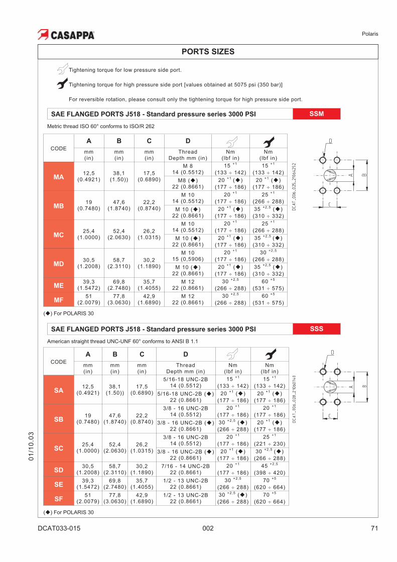
PORTS SIZES
01
/10
.03
Tightening torque for low pressure side port.
Tightening torque for high pressure side port [values obtained at 5075 psi (350 bar)]
For reversible rotation, please consult only the tightening torque for high pressure side port.
SAE FLANGED PORTS J518 - Standard pressure series 3000 PSI SSM
Metric thread ISO 60° conforms to ISO/R 262
CODE
A B C D
mm(in)
mm(in)
mm(in)
ThreadDepth mm (in)
Nm(lbf in)
Nm(lbf in)
MA12,5
(0.4921)38,1
(1.50))17,5
(0.6890)
M 814 (0.5512)
15+1
(133 � 142)
15+1
(133 � 142)
M8 (�)22 (0.8661)
20+1
(�)
(177 � 186)
20+1
(�)
(177 � 186)
MB19
(0.7480)47,6
(1.8740)22,2
(0.8740)
M 1014 (0.5512)
20+1
(177 � 186)
25+1
(266 � 288)
M 10 (�)22 (0.8661)
20+1
(�)
(177 � 186)
35+2,5
(�)
(310 � 332)
MC25,4
(1.0000)52,4
(2.0630)26,2
(1.0315)
M 1014 (0.5512)
20+1
(177 � 186)
25+1
(266 � 288)
M 10 (�)22 (0.8661)
20+1
(�)
(177 � 186)
35+2,5
(�)
(310 � 332)
MD30,5
(1.2008)58,7
(2.3110)30,2
(1.1890)
M 1015 (0,5906)
20+1
(177 � 186)
30+2,5
(266 � 288)
M 10 (�)22 (0.8661)
20+1
(�)
(177 � 186)
35+2,5
(�)
(310 � 332)
ME39,3
(1.5472)69,8
(2.7480)35,7
(1.4055)M 12
22 (0.8661)
30+2,5
(266 � 288)
60+5
(531 � 575)
MF51
(2.0079)77,8
(3.0630)42,9
(1.6890)M 12
22 (0.8661)
30+2,5
(266 � 288)
60+5
(531 � 575)
(�) For POLARIS 30
SAE FLANGED PORTS J518 - Standard pressure series 3000 PSI SSS
American straight thread UNC-UNF 60° conforms to ANSI B 1.1
CODE
A B C D
mm(in)
mm(in)
mm(in)
ThreadDepth mm (in)
Nm(lbf in)
Nm(lbf in)
SA12,5
(0.4921)38,1
(1.50))17,5
(0.6890)
5/16-18 UNC-2B14 (0.5512)
15+1
(133 � 142)
15+1
(133 � 142)
5/16-18 UNC-2B (�)22 (0.8661)
20+1
(�)
(177 � 186)
20+1
(�)
(177 � 186)
SB19
(0.7480)47,6
(1.8740)22,2
(0.8740)
3/8 - 16 UNC-2B14 (0.5512)
20+1
(177 � 186)
20+1
(177 � 186)
3/8 - 16 UNC-2B (�)22 (0.8661)
30+2,5
(�)
(266 � 288)
20+1
(�)
(177 � 186)
SC25,4
(1.0000)52,4
(2.0630)26,2
(1.0315)
3/8 - 16 UNC-2B14 (0.5512)
20+1
(177 � 186)
25+1
(221 � 230)
3/8 - 16 UNC-2B (�)22 (0.8661)
20+1
(�)
(177 � 186)
30+2,5
(�)
(266 � 288)
SD30,5
(1.2008)58,7
(2.3110)30,2
(1.1890)7/16 - 14 UNC-2B
22 (0.8661)
20+1
(177 � 186)
45+2,5
(398 � 420)
SE39,3
(1.5472)69,8
(2.7480)35,7
(1.4055)1/2 - 13 UNC-2B
22 (0.8661)
30+2,5
(266 � 288)
70+5
(620 � 664)
SF51
(2.0079)77,8
(3.0630)42,9
(1.6890)1/2 - 13 UNC-2B
22 (0.8661)
30+2,5
(�)
(266 � 288)
70+5
(620 � 664)
(�) For POLARIS 30
Polaris
72 002 DCAT033-015
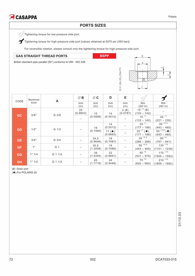
Tightening torque for low pressure side port.
Tightening torque for high pressure side port [values obtained at 5075 psi (350 bar)]
For reversible rotation, please consult only the tightening torque for high pressure side port.
PORTS SIZES
GAS STRAIGHT THREAD PORTS BSPP
British standard pipe parallel (55°) conforms to UNI - ISO 228
CODENominal
sizeA
� B � C D E
mm(in)
mm(in)
mm(in)
mm(in)
Nm(lbf in)
Nm(lbf in)
GC 3/8" G 3/8
25(0.9843) 15
(0.5906)14
(0.5512)
2 (#)(0.0787)
15+1
(#)
(133 � 142)–
– –15
+1
(133 � 142)
25+1
(221 � 230)
GD 1/2" G 1/2 –19
(0.7480)
14(0.5512)
–20
+1
(177 � 186)
50+2,5
(443 � 465)
17 (�)(0.6693)
–20
+1(�)
(177 � 186)
50+2,5
(�)
(443 � 465)
GE 3/4" G 3/4 –24,5
(0.9646)18
(0.7087)–
30+2,5
(266 � 288)
90+5
(797 � 841)
GF 1" G 1 –30,5
(1.2008)18
(0.7086)–
50+2,5
(443 � 465)
130+10
(1151 � 1239)
GG 1" 1/4 G 1 1/4 –39
(1.5354)22
(0.8661)–
60+5
(531 � 575)
170+10
(1505 � 1593)
GH 1" 1/2 G 1 1/2 –45
(1.7716)24
(0.9448)–
70+5
(620 � 664)
210+15
(1859 � 1992)
(#) Drain port
(�) For POLARIS 20
01
/10
.03
Polaris
DCAT033-015 002 73
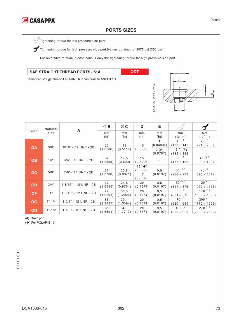
PORTS SIZES
Tightening torque for low pressure side port.
Tightening torque for high pressure side port [values obtained at 5075 psi (350 bar)]
For reversible rotation, please consult only the tightening torque for high pressure side port.
CODENominal
sizeA
� B � C D E
mm(in)
mm(in)
mm(in)
mm(in)
Nm(lbf in)
Nm(lbf in)
OA 3/8" 9/16" - 12 UNF - 2B26
(1.0236)13
(0.5118)15
(0.5906)
1(0.03934)
15+1
(133 � 142)
25+1
(221 � 230)
2 (#)(0.0787)
15+1
(#)
(133 � 142)–
OB 1/2" 3/4" - 16 UNF - 2B32
(1.2598)17,5
(0.690)15
(0.5906)–
20+1
(177 � 186)
45+2,5
(398 � 420)
OC 5/8" 7/8" - 14 UNF - 2B35
(1.3780)20,5
(0.8071)
15 (�)(0.5906) 0,5
(0.0197)
30+2,5
(266 � 288)
70+5
(620 � 664)17(0.6693)
OD 3/4" 1 1/16" - 12 UNF - 2B42
(1.6535)24,8
(0.9764)20
(0.7874)0,5
(0.0197)
40+2,5
(354 � 376)
120+10
(1062 � 1151)
OF 1" 1 5/16" - 12 UNF - 2B49
(1.9291)30,5
(1.2008)20
(0.7874)0,5
(0.0197)
60+5
(531 � 575)
170+10
(1505 � 1593)
OG 1" 1/4 1 5/8" - 12 UNF - 2B58
(2.2835)39,1
(1.5394)20
(0.7874)0,5
(0.0197)
70+5
(620 � 664)
200+10
(1770 � 1858)
OH 1" 1/2 1 7/8" - 12 UNF - 2B65
(2.5591)45
(1.7717)20
(0.7874)0,5
(0.0197)
100+5
(885 � 929)
270+15
(2389 � 2522)
(#) Drain port
(�) For POLARIS 10
SAE STRAIGHT THREAD PORTS J514 ODT
American straight thread UNC-UNF 60° conforms to ANSI B 1.1
01
/10
.03
Polaris
74 002 DCAT033-016
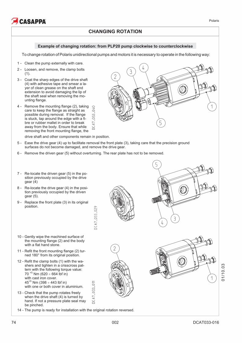
CHANGING ROTATION
1 - Clean the pump externally with care.
2 - Loosen, and remove, the clamp bolts(1).
3 - Coat the sharp edges of the drive shaft(4) with adhesive tape and smear a la-yer of clean grease on the shaft endextension to avoid damaging the lip ofthe shaft seal when removing the mo-unting flange.
4 - Remove the mounting flange (2), takingcare to keep the flange as straight aspossible during removal. If the flangeis stuck, tap around the edge with a fi-bre or rubber mallet in order to breakaway from the body. Ensure that whileremoving the front mounting flange, the
drive shaft and other components remain in position.
5 - Ease the drive gear (4) up to facilitate removal the front plate (3), taking care that the precision groundsurfaces do not become damaged, and remove the drive gear.
6 - Remove the driven gear (5) without overturning. The rear plate has not to be removed.
7 - Re-locate the driven gear (5) in the po-sition previously occupied by the drivegear (4)
8 - Re-locate the drive gear (4) in the posi-tion previously occupied by the drivengear (5).
9 - Replace the front plate (3) in its originalposition.
10 - Gently wipe the machined surface ofthe mounting flange (2) and the bodywith a flat hand stone.
11 - Refit the front mounting flange (2) tur-ned 180° from its original position.
12 - Refit the clamp bolts (1) with the wa-shers and tighten in a crisscross pat-tern with the following torque value:
70+5
Nm (620 � 664 lbf in)with cast iron cover.
45+5
Nm (398 � 443 lbf in)with one or both cover in aluminium.
13 - Check that the pump rotates freelywhen the drive shaft (4) is turned byhand. If not a pressure plate seal maybe pinched.
14 - The pump is ready for installation with the original rotation reversed.
Example of changing rotation: from PLP20 pump clockwise to counterclockwise
To change rotation of Polaris unidirectional pumps and motors it is necessary to operate in the following way:
01
/10
.03
Polaris
DCAT033-016 002 75
INSTRUCTIONS
01
/10
.03
INSTALLATION
Pump
The direction of rotation of single-rotation pumps must be the same as that of the drive shaft. Check thatthe coupling flange correctly aligns the transmission shaft and the pump shaft. Flexible couplings shouldbe used (never rigid fittings) which will not generate an axial or radial load on the pump shaft.
Motor
The direction of rotation of single-rotation motors must match circuit connections. Check that the couplingflange correctly aligns the transmission shaft and the motor shaft. Flexible couplings should be used(never rigid fittings) wich will not generate an axial or radial load on the motor shaft.
TANK
Tank capacity must be sufficient for the system’s operating conditions ( ~ 3 times the amount of oil in circu-lation) to avoid overheating of the fluid. A heat exchanger should be installed if necessary. The intake andreturn lines in the tank must be spaced apart (by inserting a vertical divider) to prevent the return-line oilfrom being taken up again immediately.
LINES
The lines must have a major diameter which is at least as large as the diameter of pump or motor ports, andmust be perfectly sealed. To reduce loss of power, the lines should be as short as possible, reducing thesources of hydraulic resistance (elbow, throttling, gate valves, etc.) to a minimum. A length of flexible tub-ing is recommended to reduce the transmission of vibrations. All return lines must end below the minimumoil level, to prevent foaming. Before connecting the lines, remove any plugs and make sure that the linesare perfectly clean.
FILTERS
We recommend filtering the entire system flow. Filters should be fitted as indicated in the first pages of thecatalogue. Only coarse filters are recommended for pump intake. Casappa recommends to use its ownproduction filters:
HYDRAULIC FLUID
Use hydraulic fluid conforming to ISO/DIN standards, having viscosity as specified in the first pages of thecatalogue. Avoid using mixtures of different oils which could result in decomposition and reduction of theoil’s lubricating power.
STARTING UP
Check that all circuit connections are tight and that the entire system is completely clean. Insert the oil inthe tank, using a filter. Bleed the circuit to assist in filling. Set the pressure relief valves to the lowest possi-ble setting. Turn on the system for a few moments at minimum speed, then bleed the circuit again andcheck the level of oil in the tank. In the difference between pump or motor temperature and fluid tempera-ture exceeds 50 °F (10 °C), rapidly switch the system on and off to heat it up gradually. Then gradually in-crease the pressure and speed of rotation until the pre-set operating levels as specified in the catalogueare attained.
PERIODICAL CHECKS - MAINTENANCE
Keep the outside surface clean especially in the area of the drive shaft seal. In fact, abrasive powder canaccelerate wear on the seal and cause leakage. Replace filters regularly to keep the fluid clean. The oillevel must be checked and oil replaced periodically depending on the system’s operating conditions.
Polaris
76 002 DCAT033-016
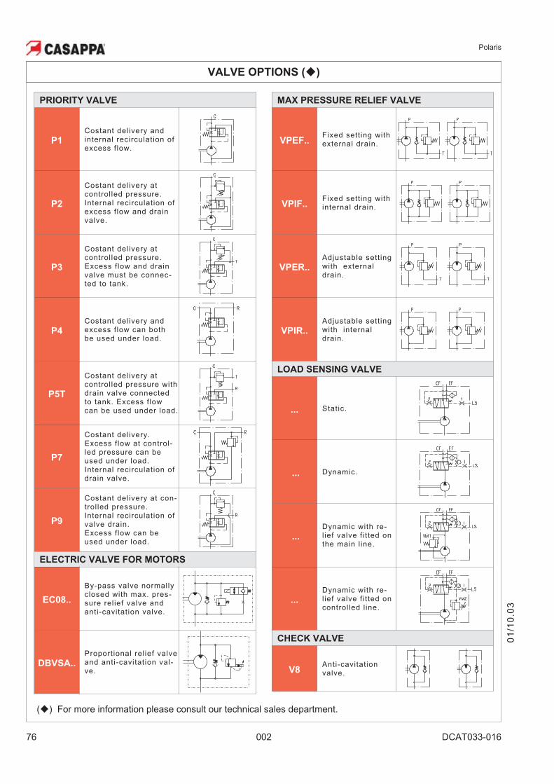
VALVE OPTIONS (�)
MAX PRESSURE RELIEF VALVE
VPEF..Fixed setting withexternal drain.
VPIF..Fixed setting withinternal drain.
VPER..
Adjustable settingwith externaldrain.
VPIR..
Adjustable settingwith internaldrain.
LOAD SENSING VALVE
... Static.
... Dynamic.
...
Dynamic with re-l ief valve fitted onthe main line.
...
Dynamic with re-l ief valve fitted oncontrolled line.
CHECK VALVE
V8Anti-cavitationvalve.
PRIORITY VALVE
P1
Costant delivery andinternal recirculation ofexcess flow.
P2
Costant delivery atcontrolled pressure.Internal recirculation ofexcess flow and drainvalve.
P3
Costant delivery atcontrolled pressure.Excess flow and drainvalve must be connec-ted to tank.
P4
Costant delivery andexcess flow can bothbe used under load.
P5T
Costant delivery atcontrolled pressure withdrain valve connectedto tank. Excess flowcan be used under load.
P7
Costant delivery.Excess flow at control-led pressure can beused under load.Internal recirculation ofdrain valve.
P9
Costant delivery at con-trol led pressure.Internal recirculation ofvalve drain.Excess flow can beused under load.
ELECTRIC VALVE FOR MOTORS
EC08..
By-pass valve normallyclosed with max. pres-sure relief valve andanti-cavitation valve.
DBVSA..
Proportional relief valveand anti-cavitation val-ve.
01
/10
.03
(�) For more information please consult our technical sales department.
Polaris
DCAT033-017 002 77
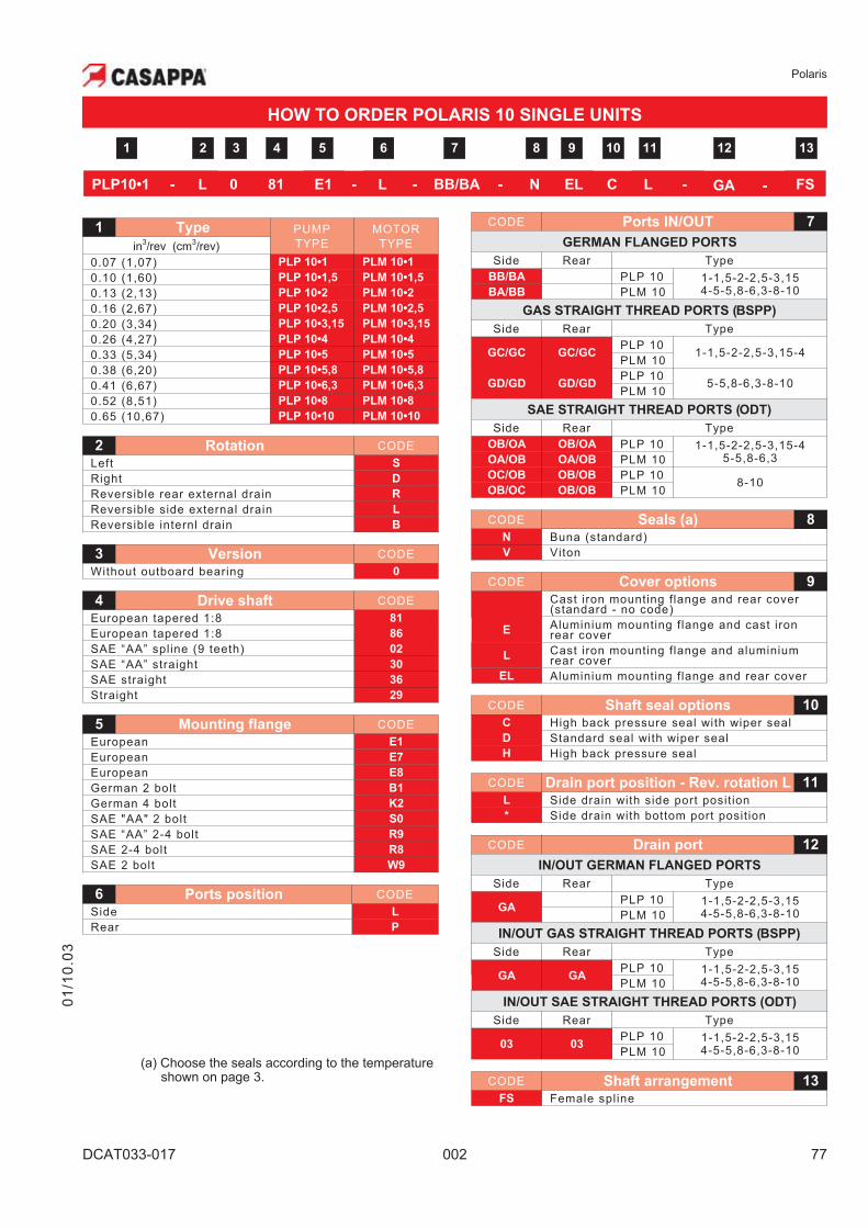
1 Type PUMP
TYPE
MOTOR
TYPEin3/rev (cm
3/rev)
0.07 (1,07) PLP 10•1 PLM 10•1
0.10 (1,60) PLP 10•1,5 PLM 10•1,5
0.13 (2,13) PLP 10•2 PLM 10•2
0.16 (2,67) PLP 10•2,5 PLM 10•2,5
0.20 (3,34) PLP 10•3,15 PLM 10•3,15
0.26 (4,27) PLP 10•4 PLM 10•4
0.33 (5,34) PLP 10•5 PLM 10•5
0.38 (6,20) PLP 10•5,8 PLM 10•5,8
0.41 (6,67) PLP 10•6,3 PLM 10•6,3
0.52 (8,51) PLP 10•8 PLM 10•8
0.65 (10,67) PLP 10•10 PLM 10•10
2 Rotation CODE
Left S
Right D
Reversible rear external drain R
Reversible side external drain L
Reversible internl drain B
3 Version CODE
Without outboard bearing 0
4 Drive shaft CODE
European tapered 1:8 81
European tapered 1:8 86
SAE “AA” spline (9 teeth) 02
SAE “AA” straight 30
SAE straight 36
Straight 29
5 Mounting flange CODE
European E1
European E7
European E8
German 2 bolt B1
German 4 bolt K2
SAE "AA" 2 bolt S0
SAE “AA” 2-4 bolt R9
SAE 2-4 bolt R8
SAE 2 bolt W9
6 Ports position CODE
Side L
Rear P
01
/10
.03
CODE Ports IN/OUT 7
GERMAN FLANGED PORTS
Side Rear Type
BB/BA PLP 10 1-1,5-2-2,5-3,154-5-5,8-6,3-8-10BA/BB PLM 10
GAS STRAIGHT THREAD PORTS (BSPP)
Side Rear Type
GC/GC GC/GCPLP 10
1-1,5-2-2,5-3,15-4PLM 10
GD/GD GD/GDPLP 10
5-5,8-6,3-8-10PLM 10
SAE STRAIGHT THREAD PORTS (ODT)
Side Rear Type
OB/OA OB/OA PLP 10 1-1,5-2-2,5-3,15-45-5,8-6,3OA/OB OA/OB PLM 10
OC/OB OB/OB PLP 108-10
OB/OC OB/OB PLM 10
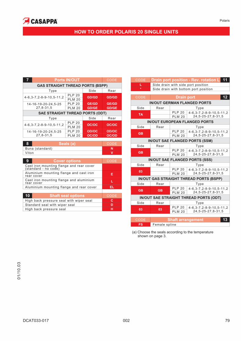
CODE Seals (a) 8
N Buna (standard)
V Viton
CODE Cover options 9
Cast iron mounting flange and rear cover(standard - no code)
EAluminium mounting flange and cast ironrear cover
LCast iron mounting flange and aluminiumrear cover
EL Aluminium mounting flange and rear cover
CODE Shaft seal options 10
C High back pressure seal with wiper seal
D Standard seal with wiper seal
H High back pressure seal
CODE Drain port position - Rev. rotation L 11
L Side drain with side port posit ion
* Side drain with bottom port posit ion
CODE Drain port 12
IN/OUT GERMAN FLANGED PORTS
Side Rear Type
GAPLP 10 1-1,5-2-2,5-3,15
4-5-5,8-6,3-8-10PLM 10
IN/OUT GAS STRAIGHT THREAD PORTS (BSPP)
Side Rear Type
GA GAPLP 10 1-1,5-2-2,5-3,15
4-5-5,8-6,3-8-10PLM 10
IN/OUT SAE STRAIGHT THREAD PORTS (ODT)
Side Rear Type
03 03PLP 10 1-1,5-2-2,5-3,15
4-5-5,8-6,3-8-10PLM 10
CODE Shaft arrangement 13
FS Female spline
HOW TO ORDER POLARIS 10 SINGLE UNITS
PLP10•1 - L 0 81 E1 - L - BB/BA - N EL C L - GA - FS
6 7 85 10 11 1392 3 41 12
(a) Choose the seals according to the temperatureshown on page 3.
Polaris
78 002 DCAT033-017
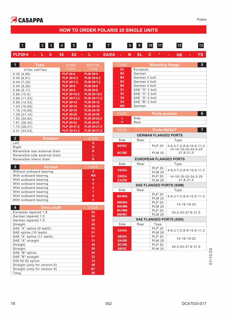
1 Type PUMP
TYPE
MOTOR
TYPEin3/rev (cm
3/rev)
0.30 (4,95) PLP 20•4 PLM 20•4
0.40 (6,61) PLP 20•6,3 PLM 20•6,3
0.44 (7,29) PLP 20•7,2 PLM 20•7,2
0.50 (8,26) PLP 20•8 PLM 20•8
0.56 (9,17) PLP 20•9 PLM 20•9
0.66 (10,9) PLP 20•10,5 PLM 20•10,5
0.69 (11,23) PLP 20•11,2 PLM 20•11,2
0.89 (14,53) PLP 20•14 PLM 20•14
1.03 (16,85) PLP 20•16 PLM 20•16
1.16 (19,09) PLP 20•19 PLM 20•19
1.29 (21,14) PLP 20•20 PLM 20•20
1.52 (24,84) PLP 20•24,5 PLM 20•24,5
1.61 (26,42) PLP 20•25 PLM 20•25
1.72 (28,21) PLP 20•27,8 PLM 20•27,8
2.01 (33,03) PLP 20•31,5 PLM 20•31,5
2 Rotation CODE
Left S
Right D
Reversible rear external drain R
Reversible side external drain L
Reversible internl drain B
3 Version CODE
Without outboard bearing 0
With outboard bearing W8
With outboard bearing 4
With outboard bearing 5
With outboard bearing 6
With outboard bearing 7
With outboard bearing 8
With outboard bearing 9
4 Drive shaft CODE
European tapered 1:8 82
German tapered 1:5 54
German tapered 1:5 55
Straight 46
SAE “A” spline (9 teeth) 03
SAE spline (10 teeth) 01
SAE “A” spline (11 teeth) 07
SAE "A" straight 31
Straight 49
Straight 50
SAE "B" spline 04
SAE "B" straight 32
DIN 54 82 spline 12
Straight (only for version 6) 48
Straight (only for version 8) B1
Tang 95
01
/10
.03
HOW TO ORDER POLARIS 20 SINGLE UNITS
CODE Mounting flange 5
E2 European
B2 German
B4 German 2 bolt
B5 German 2 bolt
B6 German 4 bolt
S1 SAE "A" 2 bolt
S2 SAE "A" 2 bolt
S9 SAE "A" 2 bolt
S5 SAE "B" 2 bolt
W8 German
CODE Ports position 6
L Side
P Rear
CODE Ports IN/OUT 7
GERMAN FLANGED PORTS
Side Rear Type
BE/BC PLP 20 4-6,3-7,2-8-9-10,5-11,214-16-19-20-24,5-25
27,8-31,5BC/BE PLM 20
EUROPEAN FLANGED PORTS
Side Rear Type
EA/EAPLP 20
4-6,3-7,2-8-9-10,5-11,2PLM 20
EB/EA PLP 20 14-16-19-20-24,5-2527,8-31,5EA/EB PLM 20
SAE FLANGED PORTS (SSM)
Side Rear Type
MA/MAPLP 20
4-6,3-7,2-8-9-10,5-11,2PLM 20
MB/MA PLP 2014-16-19-20
MA/MB PLM 20
MC/MB PLP 2024,5-25-27,8-31,5
MB/MC PLM 20
SAE FLANGED PORTS (SSS)
Side Rear Type
SA/SAPLP 20
4-6,3-7,2-8-9-10,5-11,2PLM 20
SB/SA PLP 2014-16-19-20
SA/SB PLM 20
SC/SB PLP 2024,5-25-27,8-31,5
SB/SC PLM 20
PLP20•4 - L 0 82 E2 - L - EA/EA - N EL C * - GB - FS
6 7 85 10 11 1392 3 41 12
Polaris
DCAT033-017 002 79
CODE Drain port position - Rev. rotation L 11
L Side drain with side port posit ion
* Side drain with bottom port posit ion
CODE Drain port 12
IN/OUT GERMAN FLANGED PORTS
Side Rear Type
TAPLP 20 4-6,3-7,2-8-9-10,5-11,2
24,5-25-27,8-31,5PLM 20
IN/OUT EUROPEAN FLANGED PORTS
Side Rear Type
GBPLP 20 4-6,3-7,2-8-9-10,5-11,2
24,5-25-27,8-31,5PLM 20
IN/OUT SAE FLANGED PORTS (SSM)
Side Rear Type
GBPLP 20 4-6,3-7,2-8-9-10,5-11,2
24,5-25-27,8-31,5PLM 20
IN/OUT SAE FLANGED PORTS (SSS)
Side Rear Type
03PLP 20 4-6,3-7,2-8-9-10,5-11,2
24,5-25-27,8-31,5PLM 20
IN/OUT GAS STRAIGHT THREAD PORTS (BSPP)
Side Rear Type
GB GBPLP 20 4-6,3-7,2-8-9-10,5-11,2
24,5-25-27,8-31,5PLM 20
IN/OUT SAE STRAIGHT THREAD PORTS (ODT)
Side Rear Type
03 03PLP 20 4-6,3-7,2-8-9-10,5-11,2
24,5-25-27,8-31,5PLM 20
CODE Shaft arrangement 13
FS Female spline
(a) Choose the seals according to the temperatureshown on page 3.
7 Ports IN/OUT CODE
GAS STRAIGHT THREAD PORTS (BSPP)
Type Side Rear
4-6,3-7,2-8-9-10,5-11,2PLP 20
GD/GD GD/GDPLM 20
14-16-19-20-24,5-2527,8-31,5
PLP 20 GE/GD GE/GD
PLM 20 GD/GE GD/GE
SAE STRAIGHT THREAD PORTS (ODT)
Type Side Rear
4-6,3-7,2-8-9-10,5-11,2PLP 20
OC/OC OC/OCPLM 20
14-16-19-20-24,5-2527,8-31,5
PLP 20 OD/OC OD/OC
PLM 20 OC/OD OC/OD
8 Seals (a) CODE
Buna (standard) N
Viton V
9 Cover options CODE
Cast iron mounting flange and rear cover(standard - no code)
Aluminium mounting flange and cast ironrear cover E
Cast iron mounting flange and aluminiumrear cover L
Aluminium mounting flange and rear cover EL
10 Shaft seal options CODE
High back pressure seal with wiper seal C
Standard seal with wiper seal D
High back pressure seal H
HOW TO ORDER POLARIS 20 SINGLE UNITS
01
/10
.03
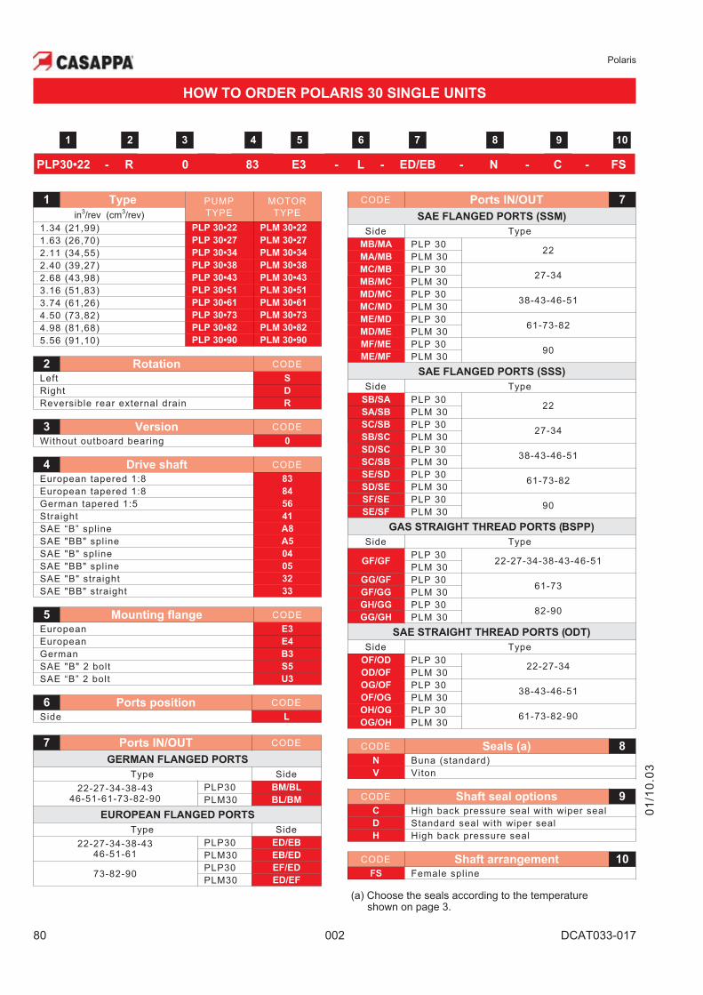
Polaris
80 002 DCAT033-017
1 Type PUMP
TYPE
MOTOR
TYPEin3/rev (cm
3/rev)
1.34 (21,99) PLP 30•22 PLM 30•22
1.63 (26,70) PLP 30•27 PLM 30•27
2.11 (34,55) PLP 30•34 PLM 30•34
2.40 (39,27) PLP 30•38 PLM 30•38
2.68 (43,98) PLP 30•43 PLM 30•43
3.16 (51,83) PLP 30•51 PLM 30•51
3.74 (61,26) PLP 30•61 PLM 30•61
4.50 (73,82) PLP 30•73 PLM 30•73
4.98 (81,68) PLP 30•82 PLM 30•82
5.56 (91,10) PLP 30•90 PLM 30•90
2 Rotation CODE
Left S
Right D
Reversible rear external drain R
3 Version CODE
Without outboard bearing 0
4 Drive shaft CODE
European tapered 1:8 83
European tapered 1:8 84
German tapered 1:5 56
Straight 41
SAE “B” spline A8
SAE "BB" spline A5
SAE "B" spline 04
SAE "BB" spline 05
SAE "B" straight 32
SAE "BB" straight 33
5 Mounting flange CODE
European E3
European E4
German B3
SAE "B" 2 bolt S5
SAE “B” 2 bolt U3
6 Ports position CODE
Side L
7 Ports IN/OUT CODE
GERMAN FLANGED PORTS
Type Side
22-27-34-38-4346-51-61-73-82-90
PLP30 BM/BL
PLM30 BL/BM
EUROPEAN FLANGED PORTS
Type Side
22-27-34-38-4346-51-61
PLP30 ED/EB
PLM30 EB/ED
73-82-90PLP30 EF/ED
PLM30 ED/EF
01
/10
.03
CODE Ports IN/OUT 7
SAE FLANGED PORTS (SSM)
Side Type
MB/MA PLP 3022
MA/MB PLM 30
MC/MB PLP 3027-34
MB/MC PLM 30
MD/MC PLP 3038-43-46-51
MC/MD PLM 30
ME/MD PLP 3061-73-82
MD/ME PLM 30
MF/ME PLP 3090
ME/MF PLM 30
SAE FLANGED PORTS (SSS)
Side Type
SB/SA PLP 3022
SA/SB PLM 30
SC/SB PLP 3027-34
SB/SC PLM 30
SD/SC PLP 3038-43-46-51
SC/SB PLM 30
SE/SD PLP 3061-73-82
SD/SE PLM 30
SF/SE PLP 3090
SE/SF PLM 30
GAS STRAIGHT THREAD PORTS (BSPP)
Side Type
GF/GFPLP 30
22-27-34-38-43-46-51PLM 30
GG/GF PLP 3061-73
GF/GG PLM 30
GH/GG PLP 3082-90
GG/GH PLM 30
SAE STRAIGHT THREAD PORTS (ODT)
Side Type
OF/OD PLP 3022-27-34
OD/OF PLM 30
OG/OF PLP 3038-43-46-51
OF/OG PLM 30
OH/OG PLP 3061-73-82-90
OG/OH PLM 30
CODE Seals (a) 8
N Buna (standard)
V Viton
CODE Shaft seal options 9
C High back pressure seal with wiper seal
D Standard seal with wiper seal
H High back pressure seal
CODE Shaft arrangement 10
FS Female spline
(a) Choose the seals according to the temperatureshown on page 3.
HOW TO ORDER POLARIS 30 SINGLE UNITS
6 7 85 102 3 41
PLP30•22 - R 0 83 E3 - L - ED/EB - N - C - FS
9
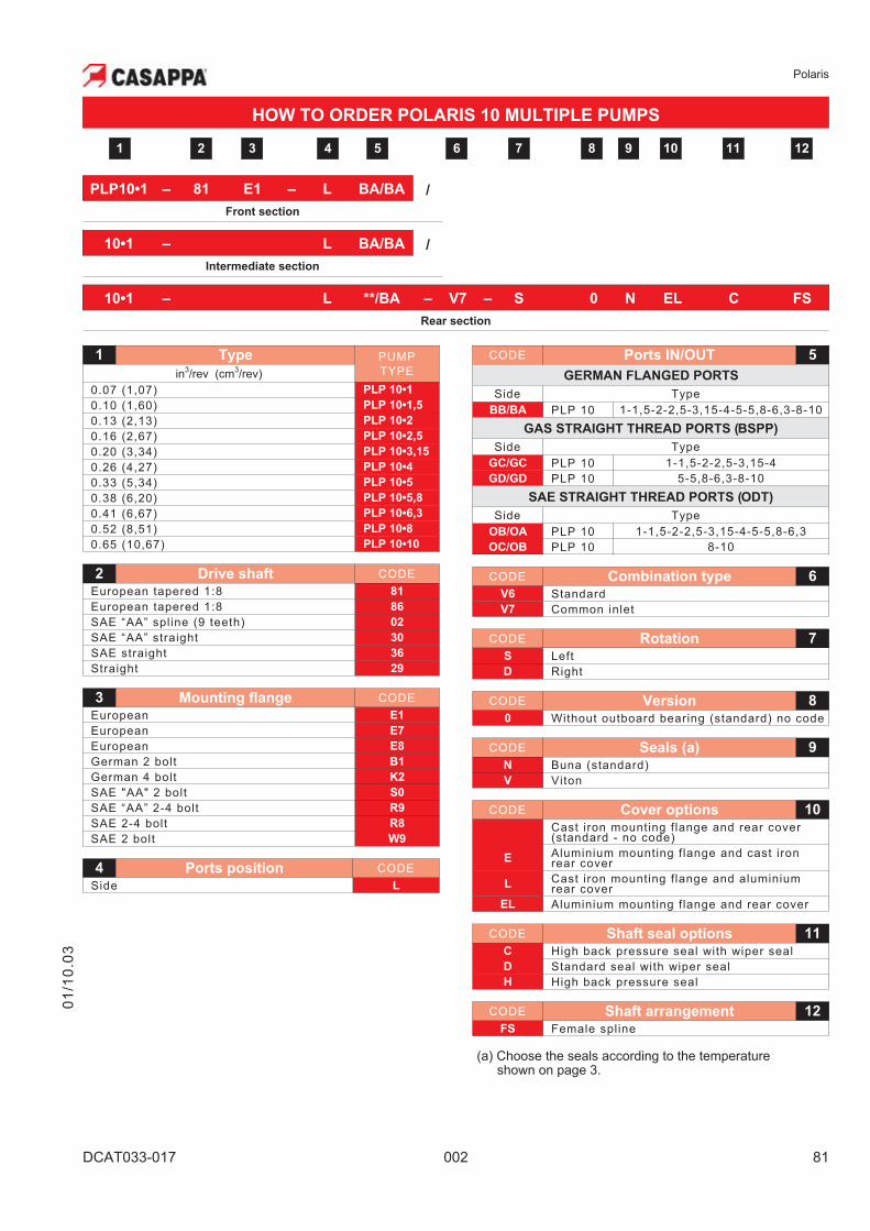
Polaris
DCAT033-017 002 81
HOW TO ORDER POLARIS 10 MULTIPLE PUMPS
01
/10
.03
PLP10•1 – 81 E1 – L BA/BA /
Front section
10•1 – L BA/BA /
Intermediate section
10•1 – L **/BA – V7 – S 0 N EL C FS
Rear section
1 Type PUMP
TYPEin3/rev (cm
3/rev)
0.07 (1,07) PLP 10•1
0.10 (1,60) PLP 10•1,5
0.13 (2,13) PLP 10•2
0.16 (2,67) PLP 10•2,5
0.20 (3,34) PLP 10•3,15
0.26 (4,27) PLP 10•4
0.33 (5,34) PLP 10•5
0.38 (6,20) PLP 10•5,8
0.41 (6,67) PLP 10•6,3
0.52 (8,51) PLP 10•8
0.65 (10,67) PLP 10•10
2 Drive shaft CODE
European tapered 1:8 81
European tapered 1:8 86
SAE “AA” spline (9 teeth) 02
SAE “AA” straight 30
SAE straight 36
Straight 29
3 Mounting flange CODE
European E1
European E7
European E8
German 2 bolt B1
German 4 bolt K2
SAE "AA" 2 bolt S0
SAE “AA” 2-4 bolt R9
SAE 2-4 bolt R8
SAE 2 bolt W9
4 Ports position CODE
Side L
CODE Ports IN/OUT 5
GERMAN FLANGED PORTS
Side Type
BB/BA PLP 10 1-1,5-2-2,5-3,15-4-5-5,8-6,3-8-10
GAS STRAIGHT THREAD PORTS (BSPP)
Side Type
GC/GC PLP 10 1-1,5-2-2,5-3,15-4
GD/GD PLP 10 5-5,8-6,3-8-10
SAE STRAIGHT THREAD PORTS (ODT)
Side Type
OB/OA PLP 10 1-1,5-2-2,5-3,15-4-5-5,8-6,3
OC/OB PLP 10 8-10
CODE Combination type 6
V6 Standard
V7 Common inlet
CODE Rotation 7
S Left
D Right
CODE Version 8
0 Without outboard bearing (standard) no code
CODE Seals (a) 9
N Buna (standard)
V Viton
CODE Cover options 10
Cast iron mounting flange and rear cover(standard - no code)
EAluminium mounting flange and cast ironrear cover
LCast iron mounting flange and aluminiumrear cover
EL Aluminium mounting flange and rear cover
CODE Shaft seal options 11
C High back pressure seal with wiper seal
D Standard seal with wiper seal
H High back pressure seal
CODE Shaft arrangement 12
FS Female spline
(a) Choose the seals according to the temperatureshown on page 3.
6 7 85 10 1192 3 41 12
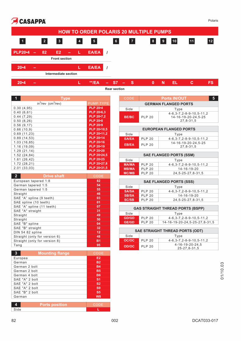
Polaris
82 002 DCAT033-017
HOW TO ORDER POLARIS 20 MULTIPLE PUMPS
PLP20•4 – 82 E2 – L EA/EA /
Front section
20•4 – L EA/EA /
Intermediate section
20•4 – L **/EA – S7 – S 0 N EL C FS
Rear section
1 Type
in3/rev (cm
3/rev) PUMP TYPE
0.30 (4,95) PLP 20•4
0.40 (6,61) PLP 20•6,3
0.44 (7,29) PLP 20•7,2
0.50 (8,26) PLP 20•8
0.56 (9,17) PLP 20•9
0.66 (10,9) PLP 20•10,5
0.69 (11,23) PLP 20•11,2
0.89 (14,53) PLP 20•14
1.03 (16,85) PLP 20•16
1.16 (19,09) PLP 20•19
1.29 (21,14) PLP 20•20
1.52 (24,84) PLP 20•24,5
1.61 (26,42) PLP 20•25
1.72 (28,21) PLP 20•27,8
2.01 (33,03) PLP 20•31,5
2 Drive shaft CODE
European tapered 1:8 82
German tapered 1:5 54
German tapered 1:5 55
Straight 46
SAE “A” spline (9 teeth) 03
SAE spline (10 teeth) 01
SAE “A” spline (11 teeth) 07
SAE "A" straight 31
Straight 49
Straight 50
SAE "B" spline 04
SAE "B" straight 32
DIN 54 82 spline 12
Straight (only for version 6) 48
Straight (only for version 8) B1
Tang 95
3 Mounting flange CODE
Europea E2
German B2
German 2 bolt B4
German 2 bolt B5
German 4 bolt B6
SAE "A" 2 bolt S1
SAE "A" 2 bolt S2
SAE "A" 2 bolt S9
SAE "B" 2 bolt S5
German W8
4 Ports position CODE
Side L
CODE Ports IN/OUT 5
GERMAN FLANGED PORTS
Side Type
BE/BC PLP 204-6,3-7,2-8-9-10,5-11,2
14-16-19-20-24,5-2527,8-31,5
EUROPEAN FLANGED PORTS
Side Type
EA/EA PLP 20 4-6,3-7,2-8-9-10,5-11,2
EB/EA PLP 2014-16-19-20-24,5-25
27,8-31,5
SAE FLANGED PORTS (SSM)
Side Type
MA/MA PLP 20 4-6,3-7,2-8-9-10,5-11,2
MB/MA PLP 20 14-16-19-20
MC/MB PLP 20 24,5-25-27,8-31,5
SAE FLANGED PORTS (SSS)
Side Type
SA/SA PLP 20 4-6,3-7,2-8-9-10,5-11,2
SB/SA PLP 20 14-16-19-20
SC/SB PLP 20 24,5-25-27,8-31,5
GAS STRAIGHT THREAD PORTS (BSPP)
Side Type
GD/GD PLP 20 4-6,3-7,2-8-9-10,5-11,2
GE/GD PLP 20 14-16-19-20-24,5-25-27,8-31,5
SAE STRAIGHT THREAD PORTS (ODT)
Side Type
OC/OC PLP 20 4-6,3-7,2-8-9-10,5-11,2
OD/OC PLP 204-16-19-20-24,5
25-27,8-31,5
6 7 85 10 1192 3 41 12
01
/10
.03
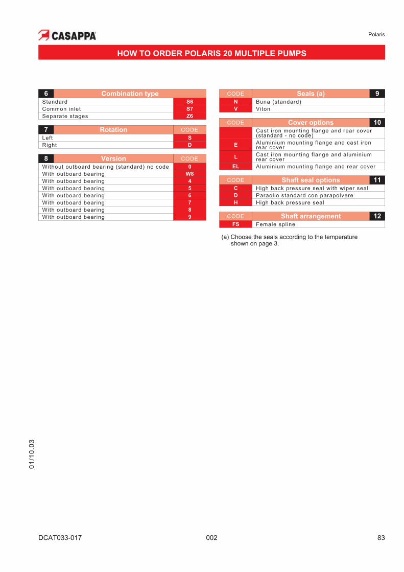
Polaris
DCAT033-017 002 83
CODE Seals (a) 9
N Buna (standard)
V Viton
CODE Cover options 10
Cast iron mounting flange and rear cover(standard - no code)
EAluminium mounting flange and cast ironrear cover
LCast iron mounting flange and aluminiumrear cover
EL Aluminium mounting flange and rear cover
CODE Shaft seal options 11
C High back pressure seal with wiper seal
D Paraolio standard con parapolvere
H High back pressure seal
CODE Shaft arrangement 12
FS Female spline
(a) Choose the seals according to the temperatureshown on page 3.
HOW TO ORDER POLARIS 20 MULTIPLE PUMPS
6 Combination type
Standard S6
Common inlet S7
Separate stages Z6
7 Rotation CODE
Left S
Right D
8 Version CODE
Without outboard bearing (standard) no code 0
With outboard bearing W8
With outboard bearing 4
With outboard bearing 5
With outboard bearing 6
With outboard bearing 7
With outboard bearing 8
With outboard bearing 9
01
/10
.03
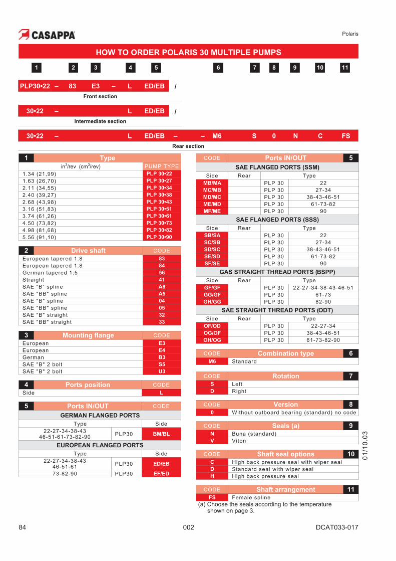
Polaris
84 002 DCAT033-017
HOW TO ORDER POLARIS 30 MULTIPLE PUMPS
PLP30•22 – 83 E3 – L ED/EB /
Front section
30•22 – L ED/EB /
Intermediate section
30•22 – L ED/EB – – M6 S 0 N C FS
Rear section
1 Type
in3/rev (cm
3/rev) PUMP TYPE
1.34 (21,99) PLP 30•22
1.63 (26,70) PLP 30•27
2.11 (34,55) PLP 30•34
2.40 (39,27) PLP 30•38
2.68 (43,98) PLP 30•43
3.16 (51,83) PLP 30•51
3.74 (61,26) PLP 30•61
4.50 (73,82) PLP 30•73
4.98 (81,68) PLP 30•82
5.56 (91,10) PLP 30•90
2 Drive shaft CODE
European tapered 1:8 83
European tapered 1:8 84
German tapered 1:5 56
Straight 41
SAE “B” spline A8
SAE "BB" spline A5
SAE "B" spline 04
SAE "BB" spline 05
SAE "B" straight 32
SAE "BB" straight 33
3 Mounting flange CODE
European E3
European E4
German B3
SAE "B" 2 bolt S5
SAE "B" 2 bolt U3
4 Ports position CODE
Side L
5 Ports IN/OUT CODE
GERMAN FLANGED PORTS
Type Side
22-27-34-38-4346-51-61-73-82-90
PLP30 BM/BL
EUROPEAN FLANGED PORTS
Type Side
22-27-34-38-4346-51-61
PLP30 ED/EB
73-82-90 PLP30 EF/ED
CODE Ports IN/OUT 5
SAE FLANGED PORTS (SSM)
Side Rear Type
MB/MA PLP 30 22
MC/MB PLP 30 27-34
MD/MC PLP 30 38-43-46-51
ME/MD PLP 30 61-73-82
MF/ME PLP 30 90
SAE FLANGED PORTS (SSS)
Side Rear Type
SB/SA PLP 30 22
SC/SB PLP 30 27-34
SD/SC PLP 30 38-43-46-51
SE/SD PLP 30 61-73-82
SF/SE PLP 30 90
GAS STRAIGHT THREAD PORTS (BSPP)
Side Rear Type
GF/GF PLP 30 22-27-34-38-43-46-51
GG/GF PLP 30 61-73
GH/GG PLP 30 82-90
SAE STRAIGHT THREAD PORTS (ODT)
Side Rear Type
OF/OD PLP 30 22-27-34
OG/OF PLP 30 38-43-46-51
OH/OG PLP 30 61-73-82-90
CODE Combination type 6
M6 Standard
CODE Rotation 7
S Left
D Right
CODE Version 8
0 Without outboard bearing (standard) no code
CODE Seals (a) 9
N Buna (standard)
V Viton
CODE Shaft seal options 10
C High back pressure seal with wiper seal
D Standard seal with wiper seal
H High back pressure seal
CODE Shaft arrangement 11
FS Female spline
(a) Choose the seals according to the temperatureshown on page 3.
75 9 10 1182 3 41 6
01
/10
.03
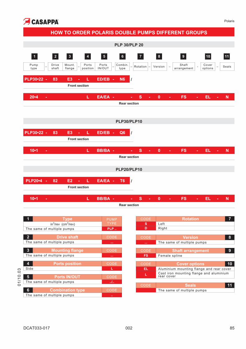
Polaris
DCAT033-017 002 85
HOW TO ORDER POLARIS DOUBLE PUMPS DIFFERENT GROUPS
CODE Rotation 7
S Left
D Right
CODE Version 8
... The same of multiple pumps
CODE Shaft arrangement 9
FS Female spline
CODE Cover options 10
EL Aluminium mounting flange and rear cover
LCast iron mounting flange and aluminiumrear cover
CODE Seals 11
The same of multiple pumps
PLP30/PLP10
PLP 30/PLP 20
01
/10
.03
1 Type PUMP
TYPEin3/rev (cm
3/rev)
The same of multiple pumps PLP ..
2 Drive shaft CODE
The same of multiple pumps ...
3 Mounting flange CODE
The same of multiple pumps ...
4 Ports position CODE
Side L
5 Ports IN/OUT CODE
The same of multiple pumps ../..
6 Combination type CODE
The same of multiple pumps ..
PLP20/PLP10
5 6 74 9 10 1182 31
Pumptype
–Driveshaft
Mount.f lange
–Ports
posit ionPorts
IN/OUT–
Combin.type
– Rotation – Version –Shaft
arrangement-
Coveroptions
– Seals
PLP30•22 - 83 E3 - L ED/EB - N6 /
Front section
20•4 - L EA/EA - - S - 0 - FS - EL - N
Rear section
PLP30•22 - 83 E3 - L ED/EB - Q6 /
Front section
10•1 - L BB/BA - - S - 0 - FS - EL - N
Rear section
PLP20•4 - 82 E2 - L EA/EA - T6 /
Front section
10•1 - L BB/BA - - S - 0 - FS - EL - N
Rear section
Polaris
86 002 DCAT033-017
NOTES
01
/10
.03

Our policy is one of continuous improvement in product. Specification of items may, therefore, be changed without
notice.
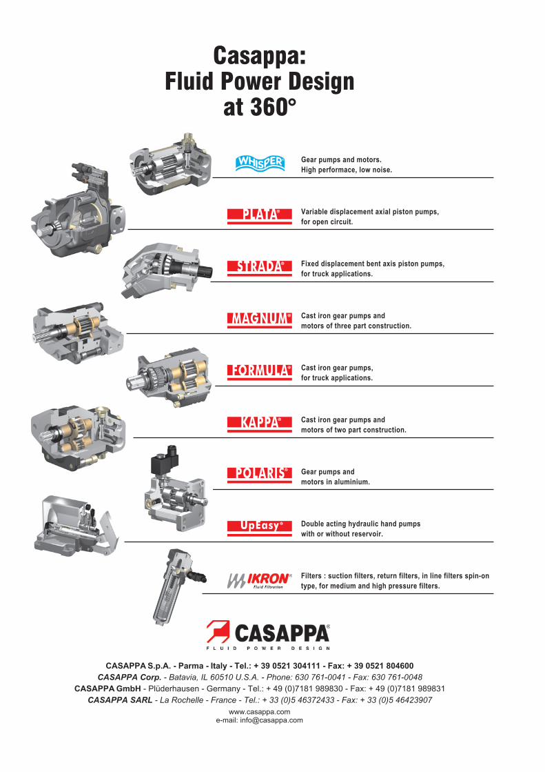
Variable displacement axial piston pumps,
for open circuit.
Fixed displacement bent axis piston pumps,
for truck applications.
Cast iron gear pumps and
motors of three part construction.
Cast iron gear pumps,
for truck applications.
Cast iron gear pumps and
motors of two part construction.
Gear pumps and
motors in aluminium.
Filters : suction filters, return filters, in line filters spin-on
type, for medium and high pressure filters.
Gear pumps and motors.
High performace, low noise.
CASAPPA S.p.A. - Parma - Italy - Tel.: + 39 0521 304111 - Fax: + 39 0521 804600
CASAPPA Corp. - Batavia, IL 60510 U.S.A. - Phone: 630 761-0041 - Fax: 630 761-0048
CASAPPA GmbH - Plüderhausen - Germany - Tel.: + 49 (0)7181 989830 - Fax: + 49 (0)7181 989831
CASAPPA SARL - La Rochelle - France - Tel.: + 33 (0)5 46372433 - Fax: + 33 (0)5 46423907
www.casappa.come-mail: [email protected]
Double acting hydraulic hand pumps
with or without reservoir.
Casappa:Fluid Power Design
at 360°