Embed Size (px)
Citation preview
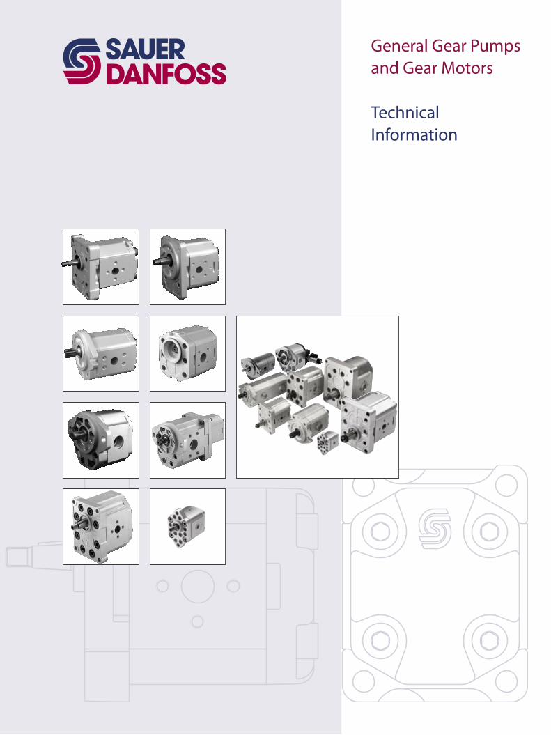
General Gear Pumps and Gear Motors
Technical Information
2 520L0557 • Rev DB • Jul 2009
General Gear Pumps and Gear MotorsTechnical Information
This manual offers the Sauer-Danfoss customer summarized technical information on all standard Sauer-Danfoss gear pumps and motors and the standard available flanges, shafts, and ports. For detailed information on a particular product, please consult the specific technical manual for that product.
Sauer-Danfoss gear pumps and motors are ideal for a wide range of applications for:• small vehicles, such as aerial lifts, greens and fairway mowers and electric forklifts.
These needs are ideally served by the aluminum pumps in the SKP1NN and SKP2NN ranges. These pumps feature integral valves and pressure balanced design for high efficiency, and extruded aluminum bodies for high strength.
• medium and large off-highway vehicles, like tractors, backhoe loaders, dumpers, and telescopic handlers, we offer the SNP2NN and SNP3NN.
Many combinations of the pumps mentioned are available as multiple units made to fit any need. Sauer-Danfoss provides standard pumps for use in industrial applications, including power packs. Advantages include small package size, quiet operations, and low installed cost.
Overview
© 2009 Sauer-Danfoss. All rights reserved.
Sauer-Danfoss accepts no responsibility for possible errors in catalogs, brochures and other printed material. Sauer-Danfoss reserves the right to alter its products without prior notice. This also applies to products already ordered provided that such alterations can be made without affecting agreed specifications. All trademarks in this material are properties of their respective owners. Sauer-Danfoss, the Sauer-Danfoss logotype, the Sauer-Danfoss S-icon, PLUS+1™, what really matters is inside® and Know-How in Motion™ are trademarks of the Sauer-Danfoss Group.
Front cover photos: F005012, F005024, F005105, F005026, F005071, F005019, F005033, F301335, F101362, F101898, F301331, F301338 and P005051..
3520L0557 • Rev DB • Jul 2009
General Gear Pumps and Gear MotorsTechnical InformationContents
General Information
Model Code
Group 0.5
Group 1
Group 2
Range .................................................................................................................................................................. 5Benefits .............................................................................................................................................................. 6Aluminum gear pumps and motors ........................................................................................................ 6
Cast-iron gear pumps and motors ...................................................................................................... 6Pump displacements .................................................................................................................................... 7Motor displacements .................................................................................................................................... 8
Model code for single pumps and motors ............................................................................................ 9
Overview .........................................................................................................................................................12Design ..............................................................................................................................................................12Features ...........................................................................................................................................................12Technical data ................................................................................................................................................12Dimensions • TFP0NN – 01FA ...................................................................................................................13
Overview .........................................................................................................................................................14Design ..............................................................................................................................................................14Features ...........................................................................................................................................................14Technical data for pumps ..........................................................................................................................15Technical data for motors .........................................................................................................................16Gear pump dimensions .............................................................................................................................17
SNP1NN – 01BA and 01DA ..................................................................................................................17SKP1NN – 02BB and 02FA ....................................................................................................................18SNP1NN, SEP1NN – 03CA .....................................................................................................................19SKP1NN – 06GA and 06SA ...................................................................................................................20
Gear motor dimensions .............................................................................................................................21SKM1NN – 01BA ......................................................................................................................................21SKM1NN, SKU1NN – 02BB and 02FA ................................................................................................22SKM1NN – 06GA and 06SA ..................................................................................................................23
Group 1 pump ports ...................................................................................................................................24Group 1 motor ports ...................................................................................................................................25Shaft and flange availability ....................................................................................................................26
Overview .........................................................................................................................................................27Design ..............................................................................................................................................................27Features ...........................................................................................................................................................27Technical data for pumps ..........................................................................................................................28Technical data for motors ..........................................................................................................................29Gear pump dimensions .............................................................................................................................30
SNP2NN – 01DA, 01FA and 01BA ......................................................................................................30SNP2NN – 02DB and 02AA ................................................................................................................31SNP2NN – 03CA .......................................................................................................................................32SNP2NN – 04/05DB and 04/05AA .....................................................................................................33SKP2NN – 06SB and SNP2NN – 06SA, 06GA .................................................................................34SNP2NN – 06SA..BxBxYY../..... ..............................................................................................................35SNP2NN – 09BJ ........................................................................................................................................36SNP2NN – A9BJ ........................................................................................................................................37
4 520L0557 • Rev DB • Jul 2009
General Gear Pumps and Gear MotorsTechnical InformationContents
Group 2
Group 3
Multi-Stage Pumps
Gear motor dimensions .............................................................................................................................38SNM2NN – 01DA, 01FA and 01BA .....................................................................................................38SNM2NN – 02DB and 02AA ................................................................................................................39SNM2NN – 03CA ......................................................................................................................................40SNM2NN – 04/05DB and 04/05AA ....................................................................................................41SNM2NN – 06GA and 06SA .................................................................................................................42
Group 2 pump ports ...................................................................................................................................43Group 2 motor ports ...................................................................................................................................44Shaft options ..................................................................................................................................................45Shaft and flange availability ....................................................................................................................45
Shaft and flange availability and torque capability ....................................................................45
Overview .........................................................................................................................................................46Design ..............................................................................................................................................................46Features ...........................................................................................................................................................46Technical data for pumps ..........................................................................................................................47Technical data for motors ..........................................................................................................................48Gear pump dimensions ..............................................................................................................................49
SNP3NN – 01FA, 01DA, 01BA and SEP3NN – 01BA ...................................................................49SNP3NN – 02FA, 02DA and 02BA ......................................................................................................50SNP3NN – 03FB and 03BB ....................................................................................................................51SNP3NN – 06DD and 06AA ..................................................................................................................52SNP3NN, SEP3NN – 07SA, 07GA ........................................................................................................53
Gear motor dimensions ............................................................................................................................54SNM3NN – 01FA, 01DA and 01BA ....................................................................................................54SNM3NN – 02FA, 02DA and 02BA .....................................................................................................55SNM3NN – 03FB and 03BB ..................................................................................................................56SNM3NN – 06DD and 06AA ................................................................................................................57SNM3NN – 07BC, 07SA and 07GA ....................................................................................................58
Group 3 pump ports ...................................................................................................................................59Group 3 motor ports ...................................................................................................................................60Shaft and flange availability ....................................................................................................................61
Shaft and flange availability and torque capability ....................................................................61
Overview .........................................................................................................................................................62Multi-stage pump model code................................................................................................................63Multi-stage pumps with European standard front flange (01) ....................................................66
5520L0557 • Rev DB • Jul 2009
General Gear Pumps and Gear MotorsTechnical InformationGeneral Information
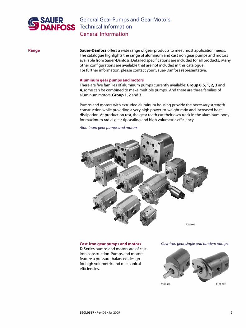
Sauer-Danfoss offers a wide range of gear products to meet most application needs. The catalogue highlights the range of aluminum and cast iron gear pumps and motors available from Sauer-Danfoss. Detailed specifications are included for all products. Many other configurations are available that are not included in this catalogue. For further information, please contact your Sauer-Danfoss representative.
Aluminum gear pumps and motorsThere are five families of aluminum pumps currently available: Group 0.5, 1, 2, 3 and 4, some can be combined to make multiple pumps. And there are three families of aluminum motors: Group 1, 2 and 3.
Pumps and motors with extruded aluminum housing provide the necessary strength construction while providing a very high power-to-weight ratio and increased heat dissipation. At production test, the gear teeth cut their own track in the aluminum body for maximum radial gear tip sealing and high volumetric efficiency.
Range
Cast-iron gear pumps and motorsD Series pumps and motors are of cast-iron construction. Pumps and motors feature a pressure-balanced design for high volumetric and mechanical efficiencies.
Cast-iron gear single and tandem pumps
Aluminum gear pumps and motors
F005 009
F101 362F101 356
6 520L0557 • Rev DB • Jul 2009
General Gear Pumps and Gear MotorsTechnical InformationGeneral Information
Sauer-Danfoss offers gear pumps and motors throughout a wide range of displacements. Each has its own unique benefits that, briefly, include in part or total: • Largedisplacementrange(from0.25to194.3cm3/rev [0.015 to 11.86 in3/rev])• Highperformanceandcosteffective• Efficientpressure-balanceddesign• Provenreliabilityandperformance• Optimumproductconfigurations• Fullrangeofauxiliaryfeatures• Compact,lightweight• Modularproductdesign• Quietoperation• Worldwidemanufacture,salesandservice
Sauer-Danfoss pumps and motors pressure-balanced design provides high efficiency throughout a given range of displacements.
One-piece gear/shaft construction provides both high strength and an accurate profile. Each integral gear/shaft is constructed of bearing-quality hardened-steel that is machined to precise tolerances for minimum leakage. This one-piece design also eliminates the potential problems of stress-fatigue often associated with two-piece designs.
All Sauer-Danfoss gear pumps use hydrodynamic journal bearings that have an oil film maintained between the gear/shaft and bearing surfaces at all times. If this oil film is sufficiently sustained through proper system maintenance and operating within recommended limits a long pump life can be expected.
Benefits
7520L0557 • Rev DB • Jul 2009
General Gear Pumps and Gear MotorsTechnical Information
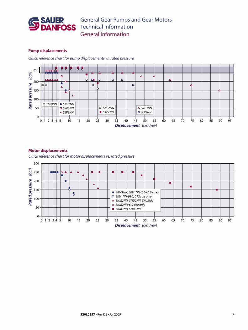
Pump displacements
Quick reference chart for pump displacements vs. rated pressure
Motor displacementsQuick reference chart for motor displacements vs. rated pressure
General Information
Displacement (cm3/rev)
Rate
d pr
essu
re
(bar
)
300
250
200
150
100
50
00 1 2 3 4 5 10 15 20 25 30 35 40 45 50 55 60 65 70 75 80 85 90 95
SKM1NN, SKU1NN/2,6÷7,8 sizes SKU1NN/010, 012 size onlySNM2NN, SNU2NN, SKU2NNSNM2NN/6,0 size onlySNM3NN, SNU3NN
Displacement (cm3/rev)
Rate
d pr
essu
re
(bar
)
200
150
100
50
0 5 10 15 20 25 30 35 40 45 50 55 60 65 70 75 80 85 90 95
SNP1NNSKP1NNSEP1NN
TFP0NNSNP2NNSKP2NN
SNP3NNSEP3NN
250{
0 1 2 3 4

8 520L0557 • Rev DB • Jul 2009
General Gear Pumps and Gear MotorsTechnical InformationProduct Coding
Model code for single pumps and motors
A B C D E F G H I J K L M N/
A TypePu
mps
TFP0NN, SNP1NN, SNP2NN, SNP3NN Standard gear pumps
SKP1NN, SKP2NN Hightorquegearpumps
SEP1NN, SEP2NN, SEP3NN Medium pressure gear pumps
SNP1IN, SNP2IN Gear pumps with internal drain relief valve
Mot
ors SKM1NN, SNM2NN, SNM3NN Standard bi-directional gear motors
SKU1NN, SKU2NN Hightorqueuni-directionalgearmotors
SNU1NN, SNU2NN, SNU3NN Uni-directional gear motors
B Displacement
Legend:
Standard
❍ Optional
– Not Available
Gro
up 1
pum
ps
Fram
e si
ze
Displacement cm3/rev [in3/rev]
SNP1
NN
SEP1
NN
SKP1
NN
SNP1
IN
1,2 1.18 [0.072]
1,7 1.57 [0.096]
2,2 2.09 [0.128]
2,6 2.62 [0.160]
3,2 3.14 [0.192]
3,8 3.66 [0.223]
4,3 4.19 [0.256]
6,0 5.89 [0.359]
7,8 7.59 [0.463]
010 9.94 [0.607] – – –
012 12.0 [0.732] – – –
Gro
up 2
pum
ps
Fram
e si
ze
Displacement cm3/rev [in3/rev]
SNP2
NN
SEP2
NN
SKP2
NN
SNP2
IN
4,0 3.9 [0.24]
6,0 6.0 [0.37]
8,0 8.4 [0.51]
011 10.8 [0.66]
014 14.4 [0.88]
017 16.8 [1.02]
019 19.2 [1.17]
022 22.8 [1.39]
025 25.2 [1.54]
Gro
up 3
pum
ps
Fram
e si
zeDisplacement cm3/rev [in3/rev]
SNP3
NN
SEP3
NN
022 22.1 [1.35]
026 26.2 [1.60]
033 33.1 [2.02]
038 37.9 [2.32]
044 44.1 [2.69]
048 48.3 [2.93] –
055 55.1 [3.36] –
063 63.4 [3.87] –
075 74.4 [4.54] –
090 88.2 [5.38] –
Gro
up 3
mot
ors
Fram
e si
ze
Displacement cm3/rev [in3/rev]
SNM
3NN
SNU
3NN
022 22.1 [1.35]
026 26.2 [1.60]
033 33.1 [2.02]
038 37.9 [2.32]
044 44.1 [2.69]
048 48.3 [2.93]
055 55.1 [3.36]
063 63.4 [3.87]
075 74.4 [4.54]
090 88.2 [5.38]
Gro
up 1
mot
ors Fr
ame
size
Displacement cm3/rev [in3/rev]
SKM
1NN
SKU
1NN
SNU
1NN
2,6 2.62 [0.160]
3,2 3.14 [0.192]
3,8 3.66 [0.223]
4,3 4.19 [0.256]
6,0 5.89 [0.359]
7,8 7.59 [0.463]
010 9.94 [0.607]
012 12.0 [0.732]
Gro
up 2
mot
ors Fr
ame
size
Displacement cm3/rev [in3/rev]
SNM
2NN
SKU
2NN
SNU
2NN
6,0 6.0 [0.37] – –
8,0 8.4 [0.51]
011 10.8 [0.66]
014 14.4 [0.88]
017 16.8 [1.02]
019 19.2 [1.17]
022 22.8 [1.39]
025 25.2 [1.54]
Gro
up 0
.5 p
ump
Frame sizeDisplacementcm3/rev [in3/rev]
,25 0.25 [0.015],45 0.45 [0.027],57 0.57 [0.034],76 0.76 [0.045]1,3 1.30 [0.079]
B Displacement (cont.)
9520L0557 • Rev DB • Jul 2009
General Gear Pumps and Gear MotorsTechnical Information
Legend:
Standard
❍ Optional
– Not Available
Model code for single pumps and motors (continued)
A B C D E F G H I J K L M N/
C Direction of rotationR Righthand(clockwise)
L Lefthand(counterclockwise)
B For reversible motors
Product Coding
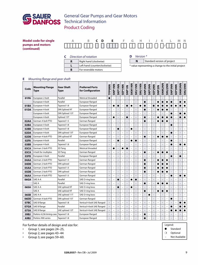
E Mounting flange and gear shaft
CodeMounting Flange Type
Gear Shaft Type
Preferred Ports for Configuration
TFP0
NN
SNP1
NN
SKP1
NN
SEP1
NN
SNP1
INSK
M1N
NSK
U1N
NSN
U1N
NSN
P2N
NSK
P2N
NSE
P2N
NSN
P2IN
SNM
2NN
SNU
2NN
SNP3
NN
SEP3
NN
SNM
3NN
SNU
3NN
01FA European 2-bolt Parallel Metrical threaded – – – – – – – – – – – – – – – – –
European 4-bolt Parallel European flanged – – – – – – – – – – –
01BA European 4-bolt Tapered 1:8 European flanged – – – –
01DA European 4-bolt DIN Splined 9T European flanged – – – – – – – – – – – – – –
European 4-bolt DIN Splined 13T European flanged – – – – – – – – – – – – – – –
European 4-bolt Splined 15T European flanged – – – – – – – – –
02AA German 4-bolt PTO Tapered 1:5 German flanged – – – – – – – – – – – – – –
02BA European 4-bolt Tapered 1:8 European flanged – – – – – – – – – – – – – – – – –
02BB European 4-bolt Tapered 1:8 European flanged – – – – – – – – – – – – – – – –
02DA European 4-bolt DIN splined 13T European flanged – – – – – – – – – – – – – – – – –
02DB German 4-bolt PTO DIN splined 9T German flanged – – – – – – – – – – – – – –
02FA European 4-bolt Parallel European flanged – – – – – – – – – – – – – –
03BB European 4-bolt Tapered 1:8 European flanged – – – – – – – – – – – – – – –
03CA German 2-bolt PTO SD Tang Metrical threaded – – – – – – – – – – – – – – –
03CA 4-bolt for multiples SD Tang German flanged – – – – – – – – – – – – – –
03FB European 4-bolt Parallel European flanged – – – – – – – – – – – – – – – –
04AA German 2-bolt PTO Tapered 1:5 German flanged – – – – – – – – – – – – – –
04DB German 2-bolt PTO DIN splined German flanged – – – – – – – – – – – – – –
05AA German 2-bolt PTO Tapered 1:5 German flanged – – – – – – – – – – – – – –
05DB German 2-bolt PTO DIN splined German flanged – – – – – – – – – – – – – –
06AA German 4-bolt PTO Tapered 1:5 German flanged – – – – – – – – – – – – – – –
06GA SAE A-A Parallel SAE O-ring boss – – – – – – – – – – – – – – –
SAE A Parallel SAE O-ring boss – – – – – – – – – – – – – –
06SA SAE A-A SAE splined 9T SAE O-ring boss – – – – – – – – – – – – – – – –
SAE A SAE splined 9T SAE O-ring boss – – – – – – – – – – – – – –
06SB SAE A-A SAE splined 11T SAE O-ring boss – – – – – – – – – – – – – – – – –
06DD German 4-bolt PTO DIN splined 15T German flanged – – – – – – – – – – – – – – – – –
07BC SAE B flange Tapered 1:8 Vertical 4-bolt SAE flanged – – – – – – – – – – – – – – – –
07GA SAE B flange Parallel Vertical 4-bolt SAE flanged – – – – – – – – – – – – – – –
07SA SAE B flange SAE splined 13T Vertical 4-bolt SAE flanged – – – – – – – – – – – – – –
09BJ Perkins 4.236 timing case Tapered 1:8 European flanged – – – – – – – – – – – – – – – – –
A9BJ Perkins 900 series Tapered 1:8 European flanged – – – – – – – – – – – – – – – – –
For further details of design and size for:• Group1,see pages 24–25, • Group2,see pages 43–44 • Group3,see pages 59–60.
D Version *N Standard version of project
* value representing a change to the initial project
10 520L0557 • Rev DB • Jul 2009
General Gear Pumps and Gear MotorsTechnical Information
Model code for single pumps and motors (continued)
A B C D E F G H I J K L M N/
Product Coding
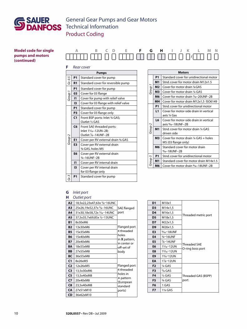
Motors
Gro
up 1
P1 Standard cover for unidirectional motor
M1 Stnd. cover for motor drain M12x1.5
M2 Coverformotordrain1⁄8 GAS
M3 Coverformotordrain¼GAS
M6 Coverformotordrain7⁄16–20UNF–2B
MH CoverformotordrainM12x1,5ISO6149
Gro
up 2
P1 Stnd. cover for unidirectional motor
L1 Coverformotor-sidedraininverticalaxis¼Gas
L6 Coverformotor-sidedraininverticalaxis 9⁄16–18UNF–2B
M1 Stnd.coverformotordrain¼GASdriven side
M3 Coverformotordrain¼GAS+holesM5(03flangeonly)
M6 Standard cover for motor drain 9⁄16–18UNF–2B G
roup
3 P1 Stnd. cover for unidirectional motor
M1 Standard cover for motor drain M14x1.5
M6 Coverformotordrain9⁄16–18UNF–2B
F Rear coverPumps
Gr.
0.5 P1 Standard cover for pump
R1 Standard cover for reversible pump
Gro
up 1
P1 Standard cover for pump03 Cover for 03 flangeI1 Cover for pump with relief valveI3 Cover for 03 flange with relief valve
Gro
up 2
P1 Standard cover for pumpP3 Cover for 03 flange onlyC1 Front BSP ports: Inlet ¾ GAS;
Outlet ½ GASC6 Front SAE threaded ports:
Inlet 11/ ₁₆–12UN–2B; Outlet ⁷/ ₈–14UNF–2B
E1 Cover per RV external drain 3⁄8 GASE3 Cover per RV external drain
3⁄8 GAS, holes M5E6 Cover per RV external drain
¾–16UNF–2BI1 Cover per RV internal drainI3 Cover per RV internal drain
for 03 flange only
Gr. 3 P1 Standard cover for pump
G Inlet port H Outlet port
A2 18,5x22,23x47,63x ³/₈–16UNC
SAE flanged port
D1 M10x1
Threaded metric port
A3 25x26,19x52,37x ³/₈–16UNC D3 M14x1,5A4 31x30,18x58,72x 7/ ₁₆–14UNC D4 M16x1,5A5 37,5x35,7x69,85x ½–13UNC D5 M18x1,5B1 8x30xM6
Flanged port4 threaded holes in X pattern, in center or off-set of body
D7 M22x1,5B2 13x30xM6 D9 M26x1,5B5 15x35xM6 E3 9/ ₁₆–18UNF
Threaded SAE O-ring boss port
B6 15x40xM6 E4 ¾–16UNFB7 20x40xM6 E5 ⁷/ ₈–14UNFBA 18x55xM8 E6 11/ ₁₆–12UNBB 27x55xM8 E8 15/ ₁₆–12UNBC 36x55xM8 E9 15/₈–12UNC1 8x26xM5
Flanged port 4 threaded holes in + pattern (European standard ports)
EA 1⁷/ ₈–12UNC2 12x26xM5 F2 ¼ GAS
Threaded GAS (BSPP) port
C3 13,5x30xM6 F3 ³/₈ GASC5 13,5x40xM8 F4 ½ GASC7 20x40xM8 F5 ¾ GASC8 23,5x40xM8 F6 1 GASCA 27x51xM10 F7 1¼ GASCD 36x62xM10
11520L0557 • Rev DB • Jul 2009
General Gear Pumps and Gear MotorsTechnical InformationProduct Coding
Model code for single pumps and motors (continued)
A B C D E F G H I J K L M N/
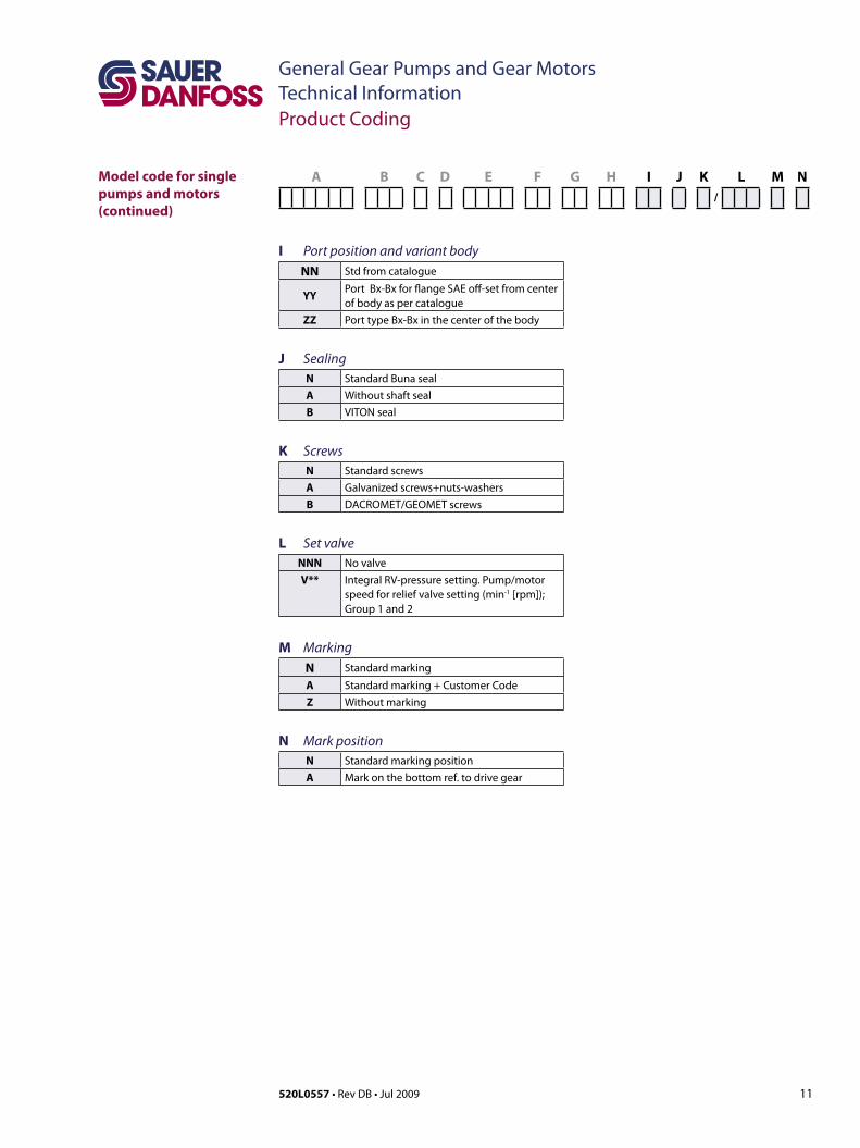
I Port position and variant bodyNN Std from catalogue
YYPort Bx-Bx for flange SAE off-set from center of body as per catalogue
ZZ Port type Bx-Bx in the center of the body
J Sealing
N Standard Buna sealA Without shaft sealB VITON seal
K Screws
N Standard screwsA Galvanized screws+nuts-washersB DACROMET/GEOMET screws
L Set valve
NNN No valveV** Integral RV-pressure setting. Pump/motor
speed for relief valve setting (min-1 [rpm]); Group 1 and 2
M Marking
N Standard marking
A Standard marking + Customer CodeZ Without marking
N Mark position
N Standard marking positionA Mark on the bottom ref. to drive gear
12 520L0557 • Rev DB • Jul 2009
General Gear Pumps and Gear MotorsTechnical InformationGroup 0.5
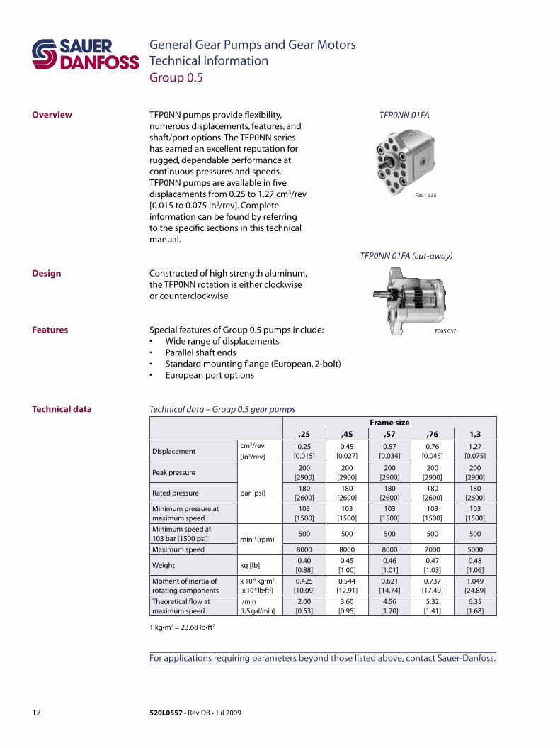
Features Special features of Group 0.5 pumps include:• Widerangeofdisplacements• Parallelshaftends• Standardmountingflange(European,2-bolt)• Europeanportoptions
Overview TFP0NN pumps provide flexibility, numerous displacements, features, and shaft/port options. The TFP0NN series has earned an excellent reputation for rugged, dependable performance at continuous pressures and speeds. TFP0NN pumps are available in five displacements from 0.25 to 1.27 cm3/rev [0.015 to 0.075 in3/rev].Completeinformation can be found by referring to the specific sections in this technical manual.
Constructedofhighstrengthaluminum,the TFP0NN rotation is either clockwise or counterclockwise.
Design
TFP0NN 01FA
F005 037
F301 335
TFP0NN 01FA (cut-away)
Technical data – Group 0.5 gear pumpsFrame size
,25 ,45 ,57 ,76 1,3
Displacementcm3/rev[in3/rev]
0.25[0.015]
0.45[0.027]
0.57[0.034]
0.76[0.045]
1.27[0.075]
Peak pressure
bar [psi]
200[2900]
200[2900]
200[2900]
200[2900]
200[2900]
Rated pressure180
[2600]180
[2600]180
[2600]180
[2600]180
[2600]Minimum pressure at maximum speed
103[1500]
103[1500]
103[1500]
103[1500]
103[1500]
Minimum speed at 103 bar [1500 psi] min-1 (rpm)
500 500 500 500 500
Maximum speed 8000 8000 8000 7000 5000
Weight kg [lb]0.40
[0.88]0.45
[1.00]0.46
[1.01]0.47
[1.03]0.48
[1.06]Moment of inertia of rotating components
x 10-6kg•m2
[x 10-6lb•ft2]0.425
[10.09]0.544
[12.91]0.621
[14.74]0.737
[17.49]1.049
[24.89]
Theoretical flow at maximum speed
l/min[US gal/min]
2.00[0.53]
3.60[0.95]
4.56[1.20]
5.32[1.41]
6.35[1.68]
1 kg•m2 = 23.68 lb•ft2
For applications requiring parameters beyond those listed above, contact Sauer-Danfoss.
Technical data

13520L0557 • Rev DB • Jul 2009
General Gear Pumps and Gear MotorsTechnical Information
mm[in]
Dimensions
P005 052E
11.5 [0.453]
7.5 [0.295]
49.5 [1.95]
TFP 50
Inlet
Outlet8 [0.315] 8 [0.315]
4 [0.157] 17 [0.669]
21 [0.827] A - A
2[0.0787]H8 4.3 [0.169]
B
A
66 [2
.6]
25.5
[1.0
]
80 [3
.15]
Ø 6
.5 [D
ia 0
.256
]
Ø 2
2 [0
.866
] f 7
Ø 7
.9 [D
ia 0
.311
]
M7
x 0.
75 [0
.029
5]
Ø 7 [Dia 0.276] h6
A
A
TFP0NN dimensionsFrame size ,25 ,45 ,57 ,76 1,3
DimensionA 53.5 [2.10] 55.0 [2.16] 56.0 [2.20] 61.5 [2.42] 61.5 [2.42]
B 26.5 [1.04] 27.3 [1.07] 27.8 [1.09] 30.5 [1.20] 30.5 [1.20]
Input/Output M10 x 1
Model code examples and maximum shaft torque Flange/drive gear Model code example Maximum shaft torque01FA TFP0NN/,57RN01FAP1D1D1NNNN/NNNNN 4.5 N•m[39.8 lb•in]
For further details on ordering, see Model Code, pages 8÷11.
Group 0.5
TFP0NN – 01FAAvailable 01FA configuration only.

14 520L0557 • Rev DB • Jul 2009
General Gear Pumps and Gear MotorsTechnical InformationGroup 1
Overview Sauer-Danfoss group 1 gear pumps and motors use an external spur gear, and positive displacement design of proven high pressure and efficiency. These high performance pumps are robustly constructed. Their durability has been proven, with many years experience, in hydraulic products for mobile and industrial applications.
Group 1 enjoy a pressure-balanced design that provides high efficiency for the entire series. Series includes the SKP1NN, SEP1NN and SNP1NN pumps, and SKM1NN motor.
Group 1 gears representatives
Features
Group 1 is made up of high performance gear pumps and motors with fixed displacements. They are available with a variety of splined, parallel, and tapered shaftends(notallareavailablewithall flange styles); see the table on shaft availability and interchangeability on the next page. Various port configurations are also available. The SKM1NN motor can work in series.
Design
Special features of Group 1 pumps and motor include:• widerangeofdisplacements(from1.2to12cm3/rev [0.072 to 0.732 in3/rev] for
pumps; from 2.6 to 12 cm3/rev [0.158 to 0.732 in3/rev] for motors)• avarietyofsplined,parallel,andtaperedshaftends• variousstandardmountingflanges• European,DIN,O-ringboss,andBSPP(gasthreaded)portoptions• multiple pump configurations, in combination with SNP1NN, SKP1NN, SNP2NN,
SKP2NN and SNP3NN.
F005 043F005 021F005 012
F005 018
F005 039
SNP1NN 01BA, SNP1IN 03CA (cut-away)
15520L0557 • Rev DB • Jul 2009
General Gear Pumps and Gear MotorsTechnical Information
Technical data for pumps
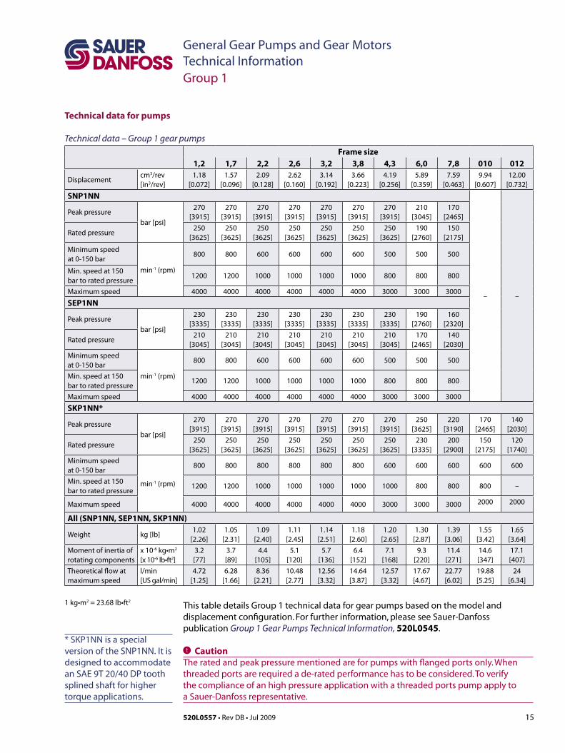
Technical data – Group 1 gear pumpsFrame size
1,2 1,7 2,2 2,6 3,2 3,8 4,3 6,0 7,8 010 012
Displacementcm3/rev[in3/rev]
1.18[0.072]
1.57[0.096]
2.09[0.128]
2.62[0.160]
3.14[0.192]
3.66[0.223]
4.19[0.256]
5.89[0.359]
7.59[0.463]
9.94[0.607]
12.00[0.732]
SNP1NN
– –
Peak pressurebar [psi]
270[3915]
270[3915]
270[3915]
270[3915]
270[3915]
270[3915]
270[3915]
210[3045]
170[2465]
Rated pressure250
[3625]250
[3625]250
[3625]250
[3625]250
[3625]250
[3625]250
[3625]190
[2760]150
[2175]
Minimum speedat 0-150 bar
min-1 (rpm)
800 800 600 600 600 600 500 500 500
Min. speed at 150 bar to rated pressure
1200 1200 1000 1000 1000 1000 800 800 800
Maximum speed 4000 4000 4000 4000 4000 4000 3000 3000 3000
SEP1NN
Peak pressurebar [psi]
230[3335]
230[3335]
230[3335]
230[3335]
230[3335]
230[3335]
230[3335]
190[2760]
160[2320]
Rated pressure210
[3045]210
[3045]210
[3045]210
[3045]210
[3045]210
[3045]210
[3045]170
[2465]140
[2030]Minimum speedat 0-150 bar
min-1 (rpm)
800 800 600 600 600 600 500 500 500
Min. speed at 150 bar to rated pressure
1200 1200 1000 1000 1000 1000 800 800 800
Maximum speed 4000 4000 4000 4000 4000 4000 3000 3000 3000
SKP1NN*
Peak pressurebar [psi]
270[3915]
270[3915]
270[3915]
270[3915]
270[3915]
270[3915]
270[3915]
250[3625]
220[3190]
170[2465]
140[2030]
Rated pressure250
[3625]250
[3625]250
[3625]250
[3625]250
[3625]250
[3625]250
[3625]230
[3335]200
[2900]150
[2175]120
[1740]Minimum speedat 0-150 bar
min-1 (rpm)
800 800 800 800 800 800 600 600 600 600 600
Min. speed at 150 bar to rated pressure
1200 1200 1000 1000 1000 1000 1000 800 800 800 –
Maximum speed 4000 4000 4000 4000 4000 4000 3000 3000 3000 2000 2000
All (SNP1NN, SEP1NN, SKP1NN)
Weight kg [lb]1.02
[2.26]1.05
[2.31]1.09
[2.40]1.11
[2.45]1.14
[2.51]1.18
[2.60]1.20
[2.65]1.30
[2.87]1.39
[3.06]1.55
[3.42]1.65
[3.64]Moment of inertia ofrotating components
x 10-6 kg•m2
[x 10-6 lb•ft2]3.2[77]
3.7[89]
4.4[105]
5.1[120]
5.7[136]
6.4[152]
7.1[168]
9.3[220]
11.4[271]
14.6[347]
17.1[407]
Theoretical flow atmaximum speed
l/min[US gal/min]
4.72[1.25]
6.28[1.66]
8.36[2.21]
10.48[2.77]
12.56[3.32]
14.64[3.87]
12.57[3.32]
17.67[4.67]
22.77[6.02]
19.88[5.25]
24[6.34]
1 kg•m2 = 23.68 lb•ft2This table details Group 1 technical data for gear pumps based on the model and displacement configuration. For further information, please see Sauer-Danfoss publication Group 1 Gear Pumps Technical Information, 520L0545.
C CautionTheratedandpeakpressurementionedareforpumpswithflangedportsonly.Whenthreaded ports are required a de-rated performance has to be considered. To verify the compliance of an high pressure application with a threaded ports pump apply to a Sauer-Danfoss representative.
Group 1
* SKP1NN is a special version of the SNP1NN. It is designed to accommodate an SAE 9T 20/40 DP tooth splined shaft for higher torque applications.
16 520L0557 • Rev DB • Jul 2009
General Gear Pumps and Gear MotorsTechnical Information
Technical data for motors
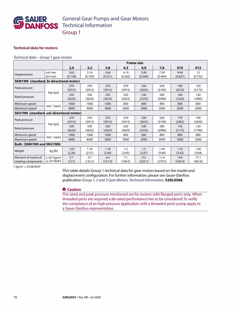
Technical data – Group 1 gear motorsFrame size
2,6 3,2 3,8 4,3 6,0 7,8 010 012
Displacementcm3/rev[in3/rev]
2.62[0.158]
3.14[0.195]
3.66[0.231]
4.19[0.262]
5.89[0.366]
7.59[0.464]
9.94[0.607]
12[0.732]
SKM1NN (standard, bi-directional motor)
Peak pressure
bar [psi]
270[3915]
270[3915]
270[3915]
270[3915]
250[3625]
220[3190]
180[2610]
150[2175]
Rated pressure250
[3625]250
[3625]250
[3625]250
[3625]230
[3335]200
[2900]160
[2320]130
[1895]
Minimum speedmin-1(rpm)
1000 1000 1000 800 800 800 800 800Maximum speed 4000 4000 3000 3000 2000 2000 2000 2000
SKU1NN (standard, uni-directional motor)
Peak pressure
bar [psi]
270[3915]
270[3915]
270[3915]
270[3915]
250[3625]
220[3190]
170[2465]
140[2030]
Rated pressure250
[3625]250
[3625]250
[3625]250
[3625]230
[3335]200
[2900]150
[2175]120
[1740]Minimum speed
min-1(rpm)1000 1000 1000 800 800 800 800 800
Maximum speed 4000 4000 3000 3000 2000 2000 2000 2000
Both (SKM1NN and SKU1NN)
Weight kg [lb]1.02
[2.26]1.14
[2.51]1.18
[2.60]1.2
[2.65]1.3
[2.87]1.39
[3.06]1.55
[3.42]1.65
[3.64]Moment of inertia ofrotating components
x 10-6kg•m2
[x 10-6lb•ft2]5.1
[121]5.7
[135.2]6.4
[151.9]7.1
[168.5]9.3
[220.7]11.4
[270.5]14.6
[339.4]17.1
[405.8]
1 kg•m2 = 23.68 lb•ft2
Group 1
This table details Group 1 technical data for gear motors based on the model and displacement configuration. For further information, please see Sauer-Danfoss publication Group 1, 2 and 3 Gear Motors, Technical Information, 520L0568.
C CautionTheratedandpeakpressurementionedareformotorswithflangedportsonly.Whenthreaded ports are required a de-rated performance has to be considered. To verify the compliance of an high pressure application with a threaded ports pump apply to a Sauer-Danfoss representative.
17520L0557 • Rev DB • Jul 2009
General Gear Pumps and Gear MotorsTechnical Information
mm[in]
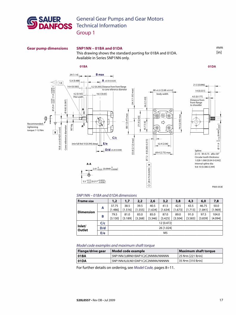
Gear pump dimensions SNP1NN – 01BA and 01DAThis drawing shows the standard porting for 01BA and 01DA. Available in Series SNP1NN only.
01BA 01DA
1:8
Co
ne
refe
ren
ce d
iam
eter
to cone reference diameter
Recommended tightening torque: 7-12 Nm
Distance from front flange
29 [1.14]
M7-
6g
14.4 [0.583] 5.2 [0.205]
12.4 [0.488]
X
Pilot width
-0.0
41-0
.020
16.5 [0.65]4.2 [0.165]
XØ
0.7
5 [0
.029
5]
body width
69.4 [2.73] max
52.4 [2.06]
88.1
[3.4
7] m
ax
74.5
[2.9
3] m
ax
(53.
8 [2
.12]
max
)(3
4.3
[1.3
5] m
ax)
(71.
9 [2
.83]
26.2
[1.0
3]45
.7 [1
.8]
68 ±0.25 [2.68 ±0.010]
5.5 [0.217 ]+0.15-0.25
+0.0059-0.0098
-0.00982.41 [0.0949 ] 0-0.025
0
D/d
E/e
C/c
Spline:Z=15 M=0.75 alfa=30°Circular tooth thickness: 1.028-1.068 [0.04 0-0.042] Internal spline dia: 9.8-10 [0.386-0.394]
to shoulderfront flangeDistance from
4.5 [0.177]
14 [0.551]
21.5 [0.846]
(min full thd 10 [0.394] deep)
±0.50 [0.020]
±0.20 [0.008]
P005 053E
B max
A
A
A
A-A
Ø 2
5.4
[1.0
]
Ø 9
.82
[0.3
87]
10.8
±0.
50 [0
.425
±0.
020]
Ø 1
1.9
[0.4
69
]
Ø 7
.2 -
8 [0
.283
-0.3
15]
0 -0.1
100 -0
.004
-0.0
016
-0.0
008
SNP1NN – 01BA and 01DA dimensionsFrame size 1,2 1,7 2,2 2,6 3,2 3,8 4,3 6,0 7,8
DimensionA 37.75
[1.486]38.5
[1.516]39.5
[1.555]40.5
[1.634]41.5
[1.634]42.5
[1.673]43.5
[1.713]46.75
[1.841]50.0
[1.969]
B 79.5[3.130]
81.0[3.189]
83.0[3.268]
85.0[3.346]
87.0[3.425]
89.0[3.504]
91.0[3.583]
97.5[3.839]
104.0[4.094]
Inlet/Outlet
C/c 12 [0.472]
D/d 26 [1.024]
E/e M5
Model code examples and maximum shaft torque Flange/drive gear Model code example Maximum shaft torque01BA SNP1NN/3,8RN01BAP1C2C2NNNN/NNNNN 25 N•m[221 lb•in]
01DA SNP1NN/6,0LN01DAP1C2C2NNNN/NNNNN 35 N•m[310 lb•in]
For further details on ordering, see Model Code, pages 8÷11.
Group 1
18 520L0557 • Rev DB • Jul 2009
General Gear Pumps and Gear MotorsTechnical Information
mm[in]
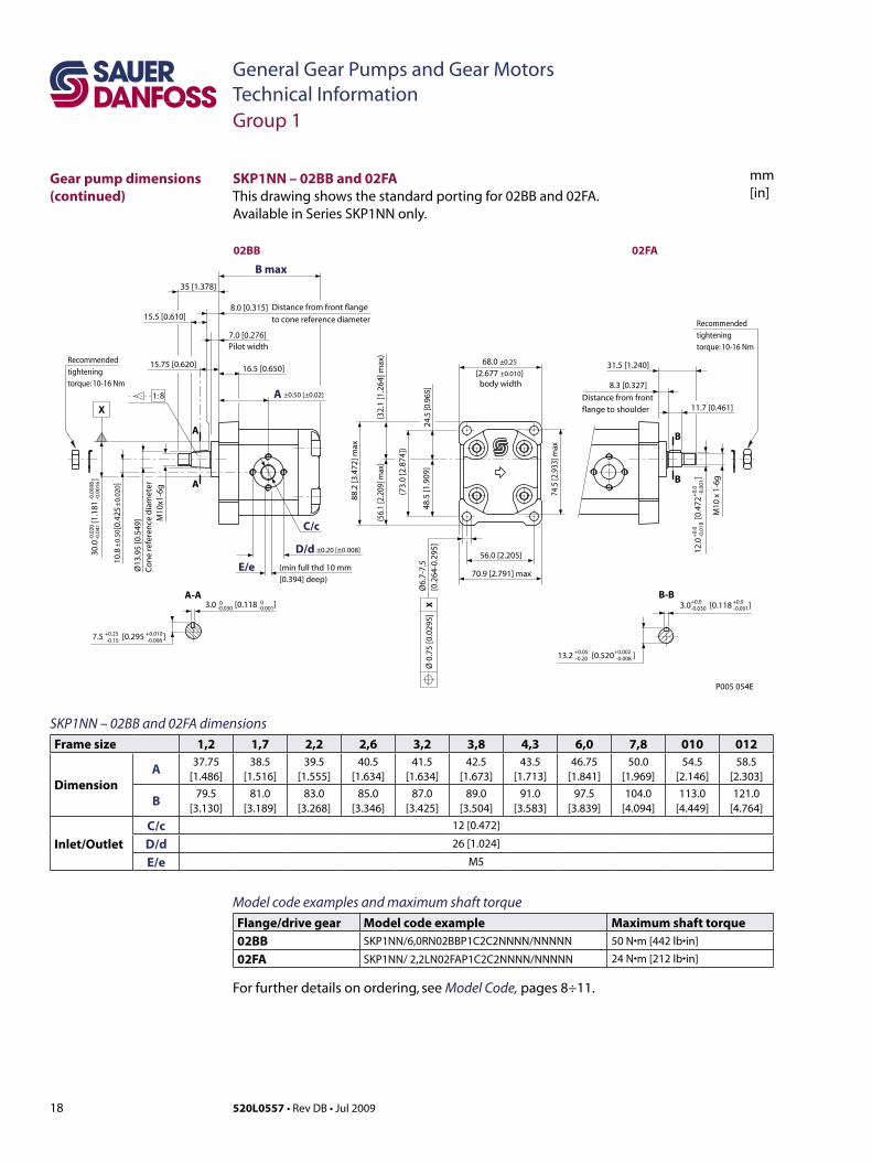
SKP1NN – 02BB and 02FA dimensionsFrame size 1,2 1,7 2,2 2,6 3,2 3,8 4,3 6,0 7,8 010 012
DimensionA 37.75
[1.486]38.5
[1.516]39.5
[1.555]40.5
[1.634]41.5
[1.634]42.5
[1.673]43.5
[1.713]46.75
[1.841]50.0
[1.969]54.5
[2.146]58.5
[2.303]
B 79.5[3.130]
81.0[3.189]
83.0[3.268]
85.0[3.346]
87.0[3.425]
89.0[3.504]
91.0[3.583]
97.5[3.839]
104.0[4.094]
113.0[4.449]
121.0[4.764]
Inlet/OutletC/c 12 [0.472]
D/d 26 [1.024]
E/e M5
Group 1
SKP1NN – 02BB and 02FAThis drawing shows the standard porting for 02BB and 02FA. Available in Series SKP1NN only.
Model code examples and maximum shaft torque Flange/drive gear Model code example Maximum shaft torque02BB SKP1NN/6,0RN02BBP1C2C2NNNN/NNNNN 50 N•m[442 lb•in]
02FA SKP1NN/ 2,2LN02FAP1C2C2NNNN/NNNNN 24 N•m[212 lb•in]
For further details on ordering, see Model Code, pages 8÷11.
12.0
[0
.472
]
+0.
0
+0.
0-0
.018
-0
.001
M10
x 1
-6g
11.7 [0.461]
8.3 [0.327]
Distance from front flange to shoulder
31.5 [1.240]
3.0 [0.118 ]+0.0+0.0-0.030 -0.001
13.2 [0.520 ]+0.05+0.002-0.20 -0.008
88.2
[3.4
72] m
ax
7.5 [0.295 ]+0.25+0.010-0.15 -0.006
3.0 [0.118 ]0 0-0.030 -0.001
C/c
D/d
E/e
A
16.5 [0.650]
7.0 [0.276]Pilot width
8.0 [0.315] Distance from front flange
to cone reference diameter
B max
M10
x1-6
g
Ø13
.95
[0.5
49]
Co
ne
refe
ren
ce d
iam
eter
10.8
[0
.425
30.0
[1
.181
]
-0.0
20
-
0.00
08-0
.041
-0.
0016
68.0 ±0.25
[2.677 ±0.010]body width
74.5
[2.9
33] m
ax56.0 [2.205]
70.9 [2.791] max
24.5
[0.9
65]
48.5
[1.9
09]
(73.
0[2
.874
])
(32.
1[1
.264
]max
)(5
6.1
[2.2
09]m
ax)
Ø6.
7-7.
5 [0
.264
-0.2
95]
1: 8
35 [1.378]
15.75 [0.620]
15.5 [0.610]
P005 054E
±0.20 [±0.008]
±0.
50
±0.
020]
±0.50 [±0.02]
02BB 02FA
(minfullthd10mm[0.394] deep)
A
A
A-A
B
B
B-B
XØ
0.7
5 [0
.029
5]
X
Recommended tightening torque: 10-16 Nm
Recommended tightening torque: 10-16 Nm
Gear pump dimensions (continued)
19520L0557 • Rev DB • Jul 2009
General Gear Pumps and Gear MotorsTechnical Information
mm[in]
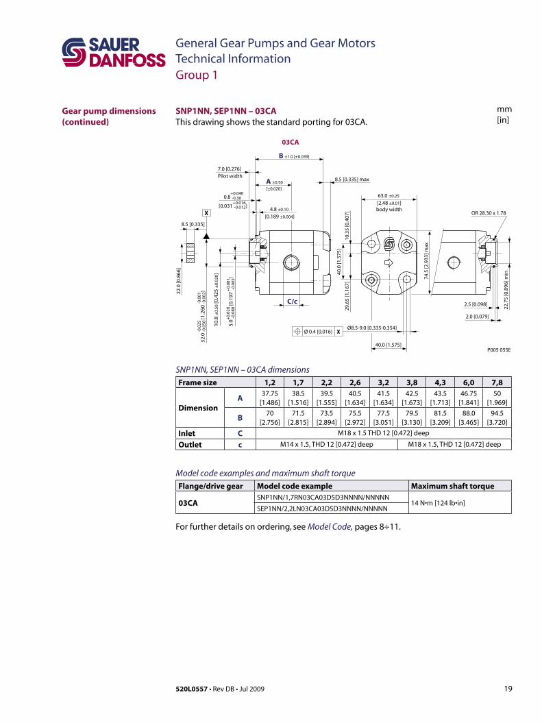
SNP1NN, SEP1NN – 03CAThisdrawingshowsthestandardportingfor03CA.
C/c 2.5 [0.098]
22.7
5 [0
.896
] min
2.0 [0.079]
OR28.30x1.78
P005 055E
8.5 [0.335]
22.0
[0.8
66]
body width
74.5
[2.9
33] m
ax
Ø8.5-9.0 [0.335-0.354]
40.0 [1.575] 4
0.0
[1.5
75]
29.6
5 [1
.167
]10
.35
[0.4
07]
8.5 [0.335] maxA ±0.50
[±0.020]
B ±1.0 [±0.039]
10.8
±0.
50 [0
.425
±0.
020]
63.0 ±0.25
[2.48 ±0.01]4.8 ±0.10
[0.189 ±0.004]
0.8 -0.30
[0.031 -0.012]
7.0 [0.276]Pilot width
5.0
-0.0
80 [0
.197
-0.0
03]
+0.
020
+0.
001
+0.040
+0.01632
.0 -0
.050
[1.2
60 -0
.002
]-0
.025
-0.0
01
XØ 0.4 [0.016]
03CA
X
SNP1NN, SEP1NN – 03CA dimensionsFrame size 1,2 1,7 2,2 2,6 3,2 3,8 4,3 6,0 7,8
DimensionA 37.75
[1.486]38.5
[1.516]39.5
[1.555]40.5
[1.634]41.5
[1.634]42.5
[1.673]43.5
[1.713]46.75
[1.841]50
[1.969]
B 70[2.756]
71.5[2.815]
73.5[2.894]
75.5[2.972]
77.5[3.051]
79.5[3.130]
81.5[3.209]
88.0[3.465]
94.5[3.720]
Inlet C M18 x 1.5 THD 12 [0.472] deep
Outlet c M14 x 1.5, THD 12 [0.472] deep M18 x 1.5, THD 12 [0.472] deep
Model code examples and maximum shaft torque Flange/drive gear Model code example Maximum shaft torque
03CASNP1NN/1,7RN03CA03D5D3NNNN/NNNNN
14 N•m[124 lb•in]SEP1NN/2,2LN03CA03D5D3NNNN/NNNNN
For further details on ordering, see Model Code, pages 8÷11.
Group 1
Gear pump dimensions (continued)

20 520L0557 • Rev DB • Jul 2009
General Gear Pumps and Gear MotorsTechnical Information
mm[in]
12.3
44
[0
.486
]
0
0 0
0 -0.0
5
Splined: SAE J498-9T-20/40DPFlat root side fitCirculartooththickness:0.127mm [0.005]less than class 1 fit
15.6 [0.614]
19.1 [0.752]
7.9 [0.311]
27.0 [1.063]
74.5
[2.9
33] m
ax
body width
R 32.1 [1.26] max
82.55 [3.258]
103.4 [4.071] max
80.2
[3.1
57] m
ax
X
10.2
-10.
8 [.4
02-.4
25]
Ø 0.75 [0.030]
3.2 [0.126 ]-0.025 -0.126
13.94-14.20 [0.549-0.559]
Straight thread
O-Ringboss
8.0 [0.315]
6.0 [0.236]
Pilot width
7.9 [0.311] Distance from front flange to shoulder
Distance from front flange to shoulder
19.1 [0.752]
27.0 [1.063]
12.7
[
0.50
0
]-0
.025
-0
.001
10.8
±0.
50 [0
.425
±0.
020]
68.0 ±0.25 [2.677 ±0.010]
50.8
[
2.0
]
0
0-0
.050
-0
.002
P005 056E
06GA 06SA
C/c
±0.50 [0.020]
B max
A
A
A
A-A
-0.1
27
00
SKP1NN – 06GA and 06SA dimensionsFrame size 1,2 1,7 2,2 2,6 3,2 3,8 4,3 6,0 7,8 010 012
DimensionA 42.25
[1.663]43
[1.693]44
[1.732]45.0
[1.772]46.0
[1.811]47
[1.850]48
[1.890]51.25
[2.018]54.5
[2.146]59
[2.323]63.5
[2.50]
B 84[3.307]
85.5[3.366]
87.5[3.445]
89.5[3.524]
91.5[3.602]
93.5[3.681]
95.5[3.760]
102[4.016]
108.5[4.272]
117.5[4.626]
125.5[4.941]
Inlet C ¾–16UNF–2B,THD14.3[0.563]deep
Outlet c 9/ 16 –18UNF–2B,THD12.7[0.500]deep
SKP1NN – 06GA and 06SAThis drawing shows the standard porting for 06GA and 06SA. Available in Series SKP1NN only.
Group 1
Gear pump dimensions (continued)
Model code examples and maximum shaft torque Flange/drive gear Model code example Maximum shaft torque06GA SKP1NN/3,2RN06GAP1E4E3NNNN/NNNNN 32 N•m[283 lb•in]
06SA SKP1NN/012LN06SAP1E4E3NNNN/NNNNN 34 N•m[301 lb•in]
For further details on ordering, see Model Code, pages 8÷11.

21520L0557 • Rev DB • Jul 2009
General Gear Pumps and Gear MotorsTechnical Information
mm[in]
SKM1NN – 01BAThis drawing shows the standard porting for 01BA. Available in Series SKM1NN only.
01BA
1:8
Co
ne
refe
ren
ce d
iam
eter
to cone reference diameter
Recommended tightening torque: 7-12 Nm
Distance from front flange
29 [1.14]
M7-
6g
14.4 [0.583] 5.2 [0.205]
12.4 [0.488]
X
Pilot width
-0.0
41-0
.020
16.5 [0.65]4.2 [0.165]
XØ
0.7
5 [0
.029
5]
body width
69.4 [2.73] max
52.4 [2.06]
88.1
[3.4
7] m
ax
74.5
[2.9
3] m
ax
(53.
8 [2
.12]
max
)(3
4.3
[1.3
5] m
ax)
(71.
9 [2
.83]
26.2
[1.0
3]45
.7 [1
.8]
68 ±0.25 [2.68 ±0.010]
5.5 [0.217 ]+0.15-0.25
+0.0059-0.0098
-0.00982.41 [0.0949 ] 0-0.025
0
D/d
E/e
C/c
(min full thd 10 [0.394] deep)
±0.50 [0.020]
±0.20 [0.008]
P005 057E
B max
A
A
A
A-A
Ø 2
5.4
[1.0
]
Ø 9
.82
[0.3
87]
10.8
±0.
50 [0
.425
±0.
020]
Ø 7
.2 -
8 [0
.283
-0.3
15]
-0.0
016
-0.0
008
21.6
±0.
50
[0.8
5 ±
0.02
0 ]
M12x1.5-6HDrain port
Group 1
Gear motor dimensions
SKM1NN – 01BA dimensionsFrame size 2,6 3,2 3,8 4,3 6,0 7,8 010 012
DimensionA 40.5
[1.594]41.5
[1.634]42.5
[1.673]43.5
[1.713]46.75
[1.841]50
[1.969]54.5
[2.146]58.5
[2.303]
B 85[3.346]
87[3.425]
89[3.504]
91[3.583]
97.5[3.839]
104[4.094]
113[4.449]
121[4.764]
Inlet/OutletC/c 12 [0.472]
D/d 26 [1.024]
E/e M5
Model code examples and maximum shaft torque Flange/drive gear Model code example Maximum shaft torque01BA SKM1NN/3,2BN01BAM1C2C2NNNN/NNNNN 25 N•m[221 lb•in]
For further details on ordering, see Model Code, pages 8÷11.
22 520L0557 • Rev DB • Jul 2009
General Gear Pumps and Gear MotorsTechnical Information
mm[in]
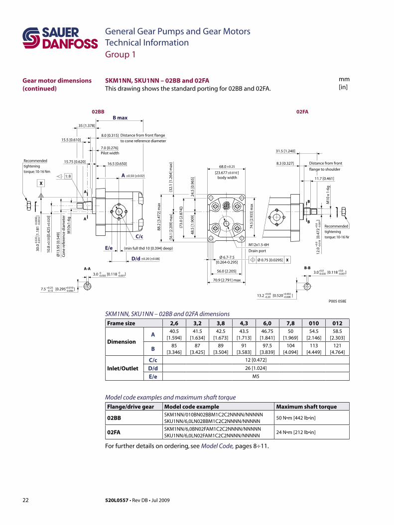
SKM1NN, SKU1NN – 02BB and 02FA dimensionsFrame size 2,6 3,2 3,8 4,3 6,0 7,8 010 012
DimensionA 40.5
[1.594]41.5
[1.634]42.5
[1.673]43.5
[1.713]46.75
[1.841]50
[1.969]54.5
[2.146]58.5
[2.303]
B 85[3.346]
87[3.425]
89[3.504]
91[3.583]
97.5[3.839]
104[4.094]
113[4.449]
121[4.764]
Inlet/OutletC/c 12 [0.472]
D/d 26 [1.024]
E/e M5
Model code examples and maximum shaft torque Flange/drive gear Model code example Maximum shaft torque
02BB SKM1NN/010BN02BBM1C2C2NNNN/NNNNNSKU1NN/6,0LN02BBM1C2C2NNNN/NNNNN
50 N•m[442 lb•in]
02FA SKM1NN/6,0BN02FAM1C2C2NNNN/NNNNNSKU1NN/6,0LN02FAM1C2C2NNNN/NNNNN
24 N•m[212 lb•in]
For further details on ordering, see Model Code, pages 8÷11.
12.0
[0
.472
]
+0.
0
+0.
0-0
.018
-0
.001
M10
x 1
-6g
11.7 [0.461]
8.3 [0.327] Distance from front
flange to shoulder
31.5 [1.240]
3.0 [0.118 ]+0.0+0.0-0.030 -0.001
13.2 [0.520 ]+0.05+0.002-0.20 -0.008
88.2
[3.4
72] m
ax
7.5 [0.295 ]+0.25+0.010-0.15 -0.006
3.0 [0.118 ]0 0-0.030 -0.001
C/c
D/d
E/e
A
A
A
A-A
16.5 [0.650]
7.0 [0.276]Pilot width
8.0 [0.315] Distance from front flange
to cone reference diameter
B max
M10
x1-6
g
Ø13
.95
[0.5
49]
Con
e re
fere
nce
dia
met
er
10.8
[0
.425
30.0
[1
.181
]
-0.0
20
-
0.00
08-0
.041
-0.
0016
68.0
[23.677 ]body width
74.5
[2.9
33] m
ax
56.0 [2.205]
70.9 [2.791] max
24.5
[0.9
65]
48.5
[1.9
09]
(73.
0[2
.874
])
(32.
1[1
.264
]max
)(5
6.1
[2.2
09]m
ax)
Ø 6.7-7.5[0.264-0.295]
1: 8
35 [1.378]
15.75 [0.620]
15.5 [0.610]
P005 058E
±0.25
±0.20 [±0.08]
±0.
50
±0.
020]
±0.50 [±0.02]±0.010
02BB 02FA
(minfullthd10[0.394]deep)
XØ 0.75 [0.0295]
M12x1.5-6H
Drain port
B
B
B-B
X
Recommended tightening torque: 10-16 Nm
Recommended tightening torque: 10-16 Nm
Group 1
SKM1NN, SKU1NN – 02BB and 02FAThis drawing shows the standard porting for 02BB and 02FA.
Gear motor dimensions (continued)
23520L0557 • Rev DB • Jul 2009
General Gear Pumps and Gear MotorsTechnical Information
mm[in]
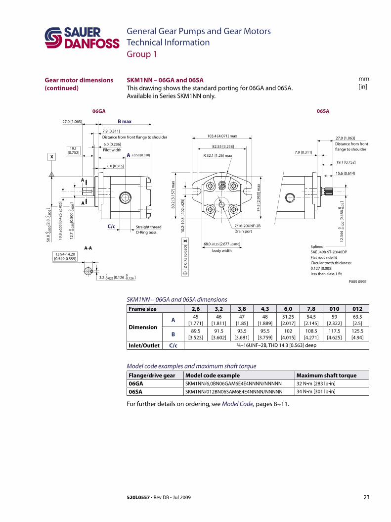
SKM1NN – 06GA and 06SA dimensionsFrame size 2,6 3,2 3,8 4,3 6,0 7,8 010 012
DimensionA 45
[1.771]46
[1.811]47
[1.85]48
[1.889]51.25
[2.017]54.5
[2.145]59
[2.322]63.5[2.5]
B 89.5[3.523]
91.5[3.602]
93.5[3.681]
95.5[3.759]
102[4.015]
108.5[4.271]
117.5[4.625]
125.5[4.94]
Inlet/Outlet C/c ¾–16UNF–2B, THD 14.3 [0.563] deep
Model code examples and maximum shaft torque Flange/drive gear Model code example Maximum shaft torque06GA SKM1NN/6,0BN06GAM6E4E4NNNN/NNNNN 32 N•m[283 lb•in]
06SA SKM1NN/012BN06SAM6E4E4NNNN/NNNNN 34 N•m[301 lb•in]
For further details on ordering, see Model Code, pages 8÷11.
12.3
44
[0
.486
]
0
0 0
0 -0.0
5
Splined: SAE J498-9T-20/40DPFlat root side fitCirculartooththickness:0.127 [0.005]less than class 1 fit
15.6 [0.614]
19.1 [0.752]
7.9 [0.311]
27.0 [1.063]
74.5
[2.9
33] m
ax
body width
R 32.1 [1.26] max
82.55 [3.258]
103.4 [4.071] max
80.2
[3.1
57] m
ax
X10
.2-1
0.8
[.402
-.425
]Ø
0.7
5 [0
.030
]
3.2 [0.126 ]-0.025 -0.126
13.94-14.20[0.549-0.559]
Straight thread O-Ringboss
8.0 [0.315]
6.0 [0.236]
Pilot width
7.9 [0.311]
Distance from front flange to shoulder
Distance from front flange to shoulder19.1
[0.752]
27.0 [1.063]
12.7
[
0.50
0
]-0
.025
-0
.001
10.8
±0.
50 [0
.425
±0.
020]
68.0 ±0.25 [2.677 ±0.010]
50.8
[
2.0
]
00
-0.0
50
-0.0
02
P005 059E
06GA 06SA
C/c
±0.50 [0.020]
B max
A
A
A
A-A
-0.1
27
00
7/16-20UNF-2BDrain port
X
Group 1
SKM1NN – 06GA and 06SAThis drawing shows the standard porting for 06GA and 06SA. Available in Series SKM1NN only.
Gear motor dimensions (continued)
24 520L0557 • Rev DB • Jul 2009
General Gear Pumps and Gear MotorsTechnical Information
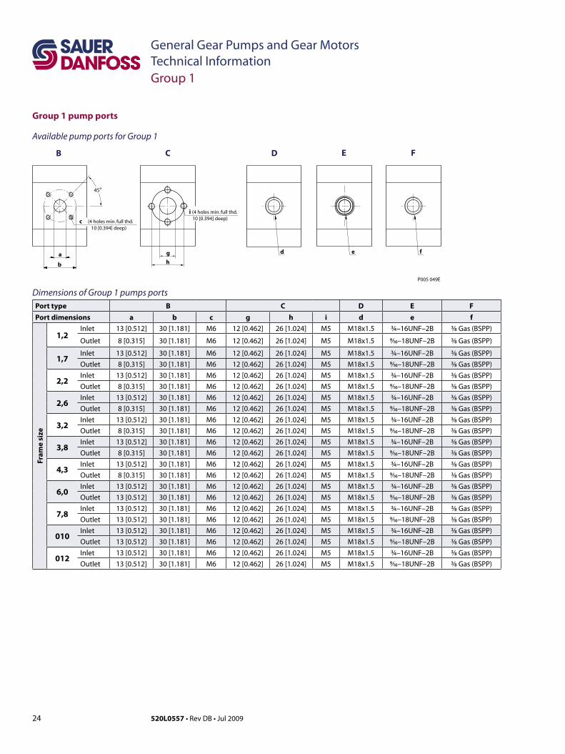
Group 1 pump ports
Group 1
Available pump ports for Group 1
Dimensions of Group 1 pumps portsPort type B C D E FPort dimensions a b c g h i d e f
Fram
e si
ze
1,2Inlet 13 [0.512] 30 [1.181] M6 12 [0.462] 26 [1.024] M5 M18x1.5 ¾–16UNF–2B ³⁄8 Gas(BSPP)
Outlet 8 [0.315] 30 [1.181] M6 12 [0.462] 26 [1.024] M5 M18x1.5 9⁄16–18UNF–2B ³⁄8 Gas(BSPP)
1,7Inlet 13 [0.512] 30 [1.181] M6 12 [0.462] 26 [1.024] M5 M18x1.5 ¾–16UNF–2B ³⁄8 Gas(BSPP)
Outlet 8 [0.315] 30 [1.181] M6 12 [0.462] 26 [1.024] M5 M18x1.5 9⁄16–18UNF–2B ³⁄8 Gas(BSPP)
2,2Inlet 13 [0.512] 30 [1.181] M6 12 [0.462] 26 [1.024] M5 M18x1.5 ¾–16UNF–2B ³⁄8 Gas(BSPP)
Outlet 8 [0.315] 30 [1.181] M6 12 [0.462] 26 [1.024] M5 M18x1.5 9⁄16–18UNF–2B ³⁄8 Gas(BSPP)
2,6Inlet 13 [0.512] 30 [1.181] M6 12 [0.462] 26 [1.024] M5 M18x1.5 ¾–16UNF–2B ³⁄8 Gas(BSPP)
Outlet 8 [0.315] 30 [1.181] M6 12 [0.462] 26 [1.024] M5 M18x1.5 9⁄16–18UNF–2B ³⁄8 Gas(BSPP)
3,2Inlet 13 [0.512] 30 [1.181] M6 12 [0.462] 26 [1.024] M5 M18x1.5 ¾–16UNF–2B ³⁄8 Gas(BSPP)
Outlet 8 [0.315] 30 [1.181] M6 12 [0.462] 26 [1.024] M5 M18x1.5 9⁄16–18UNF–2B ³⁄8 Gas(BSPP)
3,8Inlet 13 [0.512] 30 [1.181] M6 12 [0.462] 26 [1.024] M5 M18x1.5 ¾–16UNF–2B ³⁄8 Gas(BSPP)
Outlet 8 [0.315] 30 [1.181] M6 12 [0.462] 26 [1.024] M5 M18x1.5 9⁄16–18UNF–2B ³⁄8 Gas(BSPP)
4,3Inlet 13 [0.512] 30 [1.181] M6 12 [0.462] 26 [1.024] M5 M18x1.5 ¾–16UNF–2B ³⁄8 Gas(BSPP)
Outlet 8 [0.315] 30 [1.181] M6 12 [0.462] 26 [1.024] M5 M18x1.5 9⁄16–18UNF–2B ³⁄8 Gas(BSPP)
6,0Inlet 13 [0.512] 30 [1.181] M6 12 [0.462] 26 [1.024] M5 M18x1.5 ¾–16UNF–2B ³⁄8 Gas(BSPP)
Outlet 13 [0.512] 30 [1.181] M6 12 [0.462] 26 [1.024] M5 M18x1.5 9⁄16–18UNF–2B ³⁄8 Gas(BSPP)
7,8Inlet 13 [0.512] 30 [1.181] M6 12 [0.462] 26 [1.024] M5 M18x1.5 ¾–16UNF–2B ³⁄8 Gas(BSPP)
Outlet 13 [0.512] 30 [1.181] M6 12 [0.462] 26 [1.024] M5 M18x1.5 9⁄16–18UNF–2B ³⁄8 Gas(BSPP)
010Inlet 13 [0.512] 30 [1.181] M6 12 [0.462] 26 [1.024] M5 M18x1.5 ¾–16UNF–2B ³⁄8 Gas(BSPP)
Outlet 13 [0.512] 30 [1.181] M6 12 [0.462] 26 [1.024] M5 M18x1.5 9⁄16–18UNF–2B ³⁄8 Gas(BSPP)
012Inlet 13 [0.512] 30 [1.181] M6 12 [0.462] 26 [1.024] M5 M18x1.5 ¾–16UNF–2B ³⁄8Gas(BSPP)
Outlet 13 [0.512] 30 [1.181] M6 12 [0.462] 26 [1.024] M5 M18x1.5 9⁄16–18UNF–2B ³⁄8Gas(BSPP)
g
CB D FE
h
(4holesmin. full thd.10 [0.394] deep)
a
c
i
d
b
45o
(4holesmin. full thd.10 [0.394] deep)
fe
P005 049E
25520L0557 • Rev DB • Jul 2009
General Gear Pumps and Gear MotorsTechnical Information
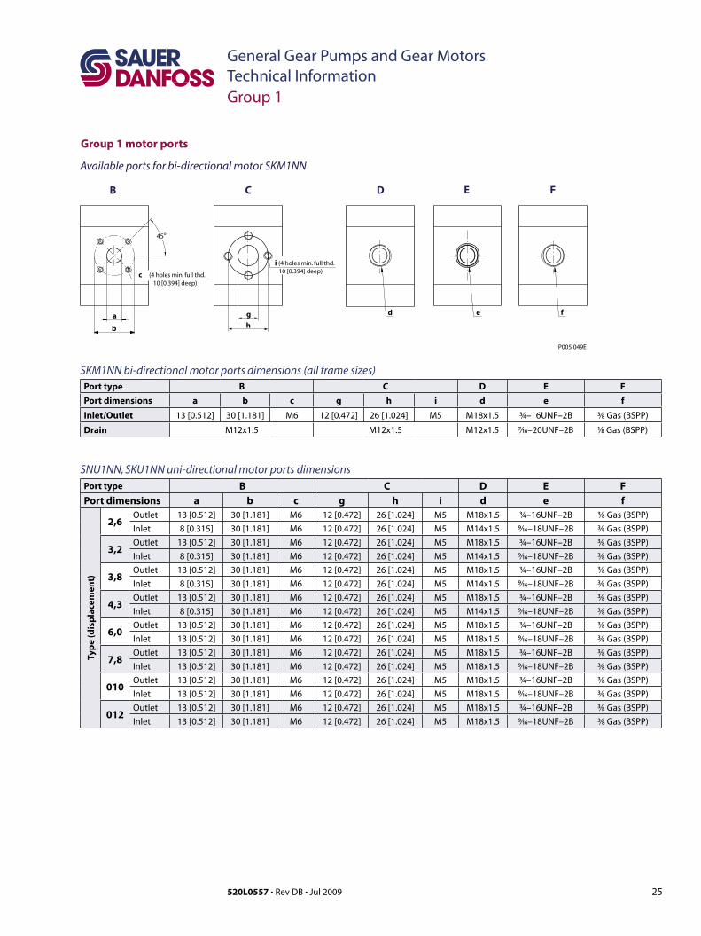
Group 1 motor ports
Group 1
g
CB D FE
h
(4holesmin. full thd.10 [0.394] deep)
a
c
i
d
b
45o
(4holesmin. full thd.10 [0.394] deep)
fe
P005 049E
Available ports for bi-directional motor SKM1NN
SKM1NN bi-directional motor ports dimensions (all frame sizes)Port type B C D E FPort dimensions a b c g h i d e f
Inlet/Outlet 13 [0.512] 30 [1.181] M6 12 [0.472] 26 [1.024] M5 M18x1.5 ¾–16UNF–2B ³⁄8Gas(BSPP)
Drain M12x1.5 M12x1.5 M12x1.5 7⁄16–20UNF–2B 1⁄8Gas(BSPP)
SNU1NN, SKU1NN uni-directional motor ports dimensionsPort type B C D E FPort dimensions a b c g h i d e f
Type
(dis
plac
emen
t)
2,6Outlet 13 [0.512] 30 [1.181] M6 12 [0.472] 26 [1.024] M5 M18x1.5 ¾–16UNF–2B ³⁄8 Gas(BSPP)
Inlet 8 [0.315] 30 [1.181] M6 12 [0.472] 26 [1.024] M5 M14x1.5 9⁄16–18UNF–2B ³⁄8 Gas(BSPP)
3,2Outlet 13 [0.512] 30 [1.181] M6 12 [0.472] 26 [1.024] M5 M18x1.5 ¾–16UNF–2B ³⁄8 Gas(BSPP)
Inlet 8 [0.315] 30 [1.181] M6 12 [0.472] 26 [1.024] M5 M14x1.5 9⁄16–18UNF–2B ³⁄8 Gas(BSPP)
3,8Outlet 13 [0.512] 30 [1.181] M6 12 [0.472] 26 [1.024] M5 M18x1.5 ¾–16UNF–2B ³⁄8 Gas(BSPP)
Inlet 8 [0.315] 30 [1.181] M6 12 [0.472] 26 [1.024] M5 M14x1.5 9⁄16–18UNF–2B ³⁄8 Gas(BSPP)
4,3Outlet 13 [0.512] 30 [1.181] M6 12 [0.472] 26 [1.024] M5 M18x1.5 ¾–16UNF–2B ³⁄8 Gas(BSPP)
Inlet 8 [0.315] 30 [1.181] M6 12 [0.472] 26 [1.024] M5 M14x1.5 9⁄16–18UNF–2B ³⁄8 Gas(BSPP)
6,0Outlet 13 [0.512] 30 [1.181] M6 12 [0.472] 26 [1.024] M5 M18x1.5 ¾–16UNF–2B ³⁄8 Gas(BSPP)
Inlet 13 [0.512] 30 [1.181] M6 12 [0.472] 26 [1.024] M5 M18x1.5 9⁄16–18UNF–2B ³⁄8 Gas(BSPP)
7,8Outlet 13 [0.512] 30 [1.181] M6 12 [0.472] 26 [1.024] M5 M18x1.5 ¾–16UNF–2B ³⁄8 Gas(BSPP)
Inlet 13 [0.512] 30 [1.181] M6 12 [0.472] 26 [1.024] M5 M18x1.5 9⁄16–18UNF–2B ³⁄8 Gas(BSPP)
010Outlet 13 [0.512] 30 [1.181] M6 12 [0.472] 26 [1.024] M5 M18x1.5 ¾–16UNF–2B ³⁄8 Gas(BSPP)
Inlet 13 [0.512] 30 [1.181] M6 12 [0.472] 26 [1.024] M5 M18x1.5 9⁄16–18UNF–2B ³⁄8 Gas(BSPP)
012Outlet 13 [0.512] 30 [1.181] M6 12 [0.472] 26 [1.024] M5 M18x1.5 ¾–16UNF–2B ³⁄8 Gas(BSPP)
Inlet 13 [0.512] 30 [1.181] M6 12 [0.472] 26 [1.024] M5 M18x1.5 9⁄16–18UNF–2B ³⁄8 Gas(BSPP)
26 520L0557 • Rev DB • Jul 2009
General Gear Pumps and Gear MotorsTechnical Information
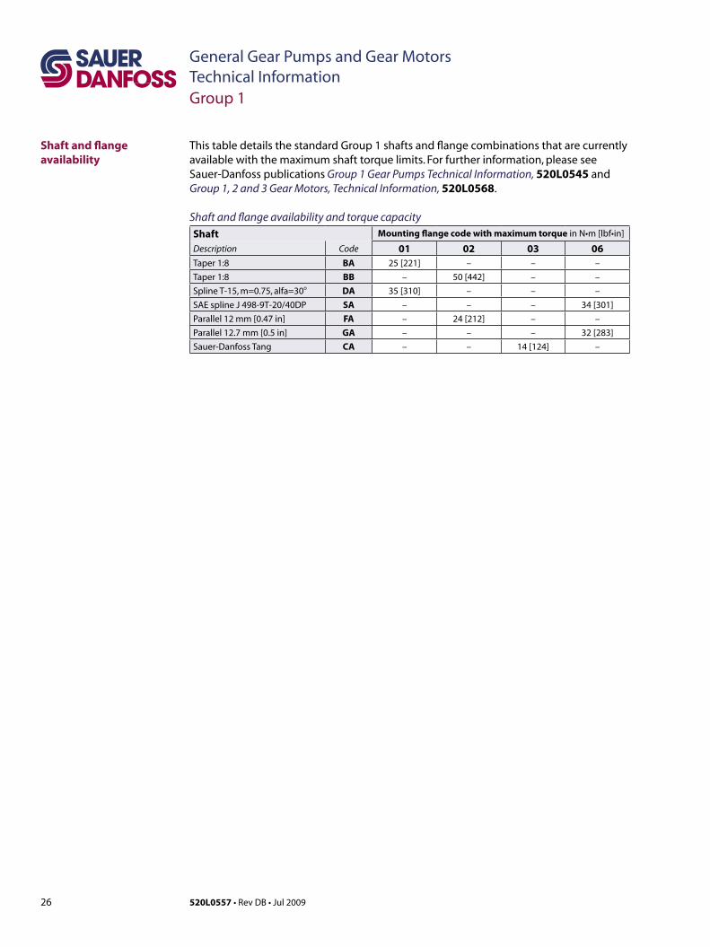
Shaft and flange availability
This table details the standard Group 1 shafts and flange combinations that are currently available with the maximum shaft torque limits. For further information, please see Sauer-Danfoss publications Group 1 Gear Pumps Technical Information, 520L0545 and Group 1, 2 and 3 Gear Motors, Technical Information, 520L0568.
Shaft and flange availability and torque capacityShaft Mounting flange code with maximum torque in N•m [lbf•in]
Description Code 01 02 03 06Taper 1:8 BA 25 [221] – – –
Taper 1:8 BB – 50 [442] – –
Spline T-15, m=0.75, alfa=30o DA 35 [310] – – –
SAE spline J 498-9T-20/40DP SA – – – 34 [301]
Parallel 12 mm [0.47 in] FA – 24 [212] – –
Parallel 12.7 mm [0.5 in] GA – – – 32 [283]
Sauer-Danfoss Tang CA – – 14 [124] –
Group 1
27520L0557 • Rev DB • Jul 2009
General Gear Pumps and Gear MotorsTechnical Information
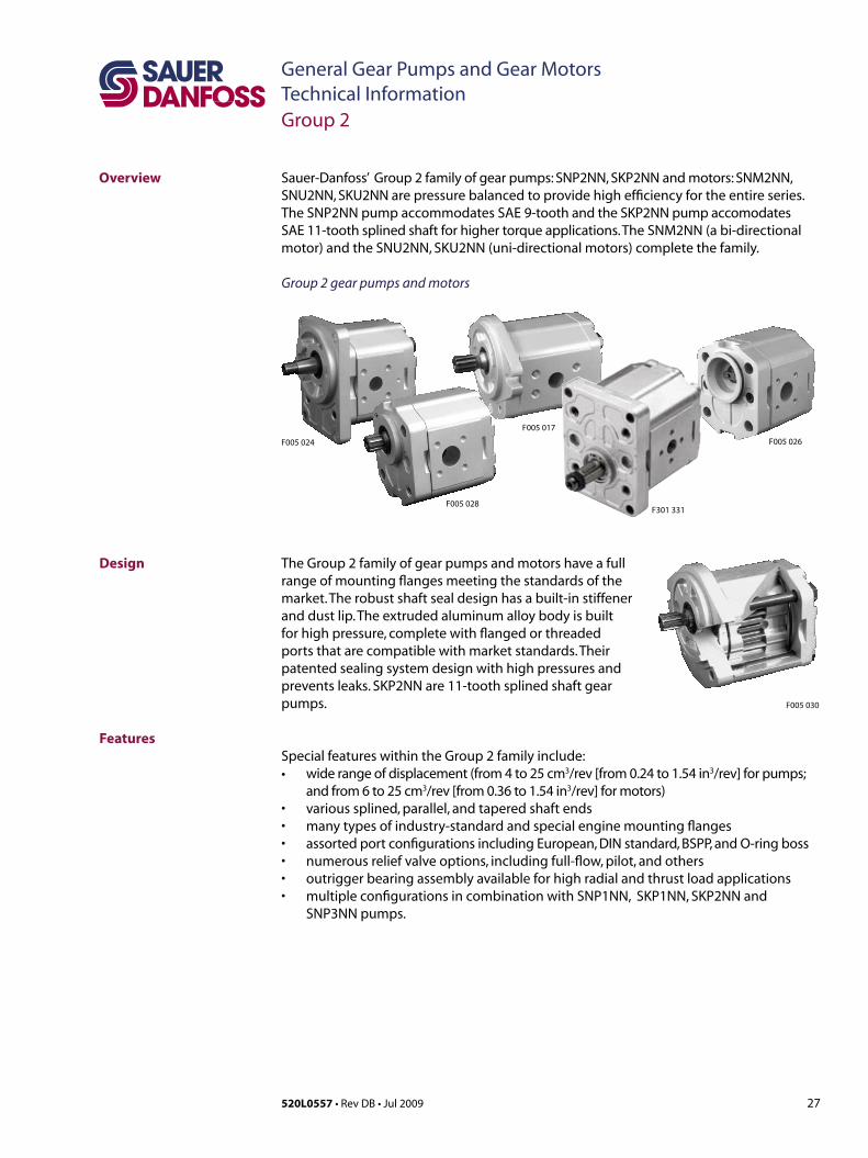
Overview Sauer-Danfoss’ Group 2 family of gear pumps: SNP2NN, SKP2NN and motors: SNM2NN, SNU2NN, SKU2NN are pressure balanced to provide high efficiency for the entire series. The SNP2NN pump accommodates SAE 9-tooth and the SKP2NN pump accomodates SAE11-toothsplinedshaftforhighertorqueapplications.TheSNM2NN(abi-directionalmotor)andtheSNU2NN,SKU2NN(uni-directionalmotors)completethefamily.
Group 2 gear pumps and motors
Design
Features
Group 2
The Group 2 family of gear pumps and motors have a full range of mounting flanges meeting the standards of the market. The robust shaft seal design has a built-in stiffener and dust lip. The extruded aluminum alloy body is built for high pressure, complete with flanged or threaded ports that are compatible with market standards. Their patented sealing system design with high pressures and prevents leaks. SKP2NN are 11-tooth splined shaft gear pumps.
Special features within the Group 2 family include: • widerangeofdisplacement(from4to25cm3/rev [from 0.24 to 1.54 in3/rev] for pumps;
and from 6 to 25 cm3/rev [from 0.36 to 1.54 in3/rev] for motors)• varioussplined,parallel,andtaperedshaftends• manytypesofindustry-standardandspecialenginemountingflanges• assortedportconfigurationsincludingEuropean,DINstandard,BSPP,andO-ringboss• numerousreliefvalveoptions,includingfull-flow,pilot,andothers• outriggerbearingassemblyavailableforhighradialandthrustloadapplications• multipleconfigurationsincombinationwithSNP1NN,SKP1NN,SKP2NNand
SNP3NN pumps.
F005 030
F005 026
F301 331F005 028
F005 017
F005 024

28 520L0557 • Rev DB • Jul 2009
General Gear Pumps and Gear MotorsTechnical Information
Technical data for pumps
Technical data – Group 2 gear pumpsFrame size
4,0 6,0 8,0 011 014 017 019 022 025
Displacementcm3/rev[in3/rev]
3.9[0.24]
6[0.37]
8.4[0.51]
10.8[0.66]
14.4[0.88]
16.8[1.02]
19.2[1.17]
22.8[1.39]
25.2[1.54]
SNP2NN
Peak pressure
bar [psi]
280[4060]
280[4060]
280[4060]
280[4060]
280[4060]
280[4060]
230[3335]
200[2900]
175[2638]
Rated pressure250
[3625]250
[3625]250
[3625]250
[3625]250
[3625]250
[3625]210
[3045]180
[2610]160
[2320]Minimum speedat 0-100 bar
min-1 (rpm)
600 600 600 500 500 500 500 500 500
Minimum speed at 100-180 bar
1200 1200 1000 800 750 750 700 700 700
Min. speed at 180 bar to rated pressure
1400 1400 1400 1200 1000 1000 1000 800 –
Maximum speed 4000 4000 4000 4000 3500 3000 3000 3000 3000
SKP2NN
Peak pressure
bar [psi]
280[4060]
280[4060]
280[4060]
280[4060]
280[4060]
280[4060]
260[3770]
230[3335]
200[2900]
Rated pressure250
[3625]250
[3625]250
[3625]250
[3625]250
[3625]250
[3625]240
[3480]210
[3045]190
[2755]Minimum speedat 0-100 bar
min-1 (rpm)
600 600 600 500 500 500 500 500 500
Minimum speed at 100-180 bar
1200 1200 1000 800 750 750 700 700 700
Min. speed at 180 bar to rated pressure
1400 1400 1400 1200 1000 1000 1000 800 800
Maximum speed 4000 4000 4000 4000 3500 3000 3000 3000 3000
Both (SNP2NN, SKP2NN)
Weight kg [lb]2.3
[5.1]2.4
[5.3]2.5
[5.5]2.7
[5.8]2.9
[6.3]3.0
[6.5]3.1
[6.7]3.2[7]
3.3[7.3]
Moment of inertia of rotating components
x 10-6kg•m2
[x 10-6lb•ft2]21.3[505]
26.5[629]
32.4[769]
38.4[911]
47.3[1122]
53.3[1265]
59.2[1405]
68.1[1616]
74.1[1758]
Theoretical flow at maximum speed
l/min[US gal/min]
15.6[4.1]
24.0[6.3]
33.6[8.9]
43.2[11.4]
50.4[13.3]
50.4[13.3]
57.6[15.2]
68.4[18]
75.6[20]
1 kg•m2 = 23.68 lb•ft2
This table details Group 2 technical data for gear pumps based on the model and displacement configuration. For further information about application and configuration of gear pumps, please see Sauer-Danfoss publication Group 2 Gear Pumps Technical Information, 520L0560.
C CautionTheratedandpeakpressurementionedareforpumpswithflangedportsonly.Whenthreaded ports are required a de-rated performance has to be considered. To verify the compliance of an high pressure application with a threaded ports pump apply to a Sauer-Danfoss representative.
Group 2
29520L0557 • Rev DB • Jul 2009
General Gear Pumps and Gear MotorsTechnical Information
Technical data for motors
Technical data – Group 2 gear motorsFrame size
6,0 8,0 011 014 017 019 022 025
Displacementcm3/rev[in3/rev]
6[0.36]
8.4[0.513]
10.8[0.659]
14.4[0.879]
16.8[1.025]
19.2[1.171]
22.8[1.391]
25.2[1.538]
SNM2NN (bi-directional motor)
Peak pressure
bar [psi]
280[4060]
280[4060]
280[4060]
280[4060]
260[3770]
230[3335]
200[2900]
180[2610]
Rated pressure250
[3625]250
[3625]250
[3625]250
[3625]230
[3335]210
[3000]180
[2610]160
[2320]
Outlet pressure250
[3625]250
[3625]250
[3625]250
[3625]230
[3335]210
[3000]180
[2610]160
[2320]
Minimum speedmin-1 (rpm)
700 700 700 700 500 500 500 500Maximum speed 4000 4000 4000 4000 4000 3500 3500 3500
SNU2NN (uni-directional motor)
Peak pressurebar [psi]
–
280[4060]
280[4060]
280[4060]
260[3770]
230[3335]
200[2900]
180[2610]
Rated pressure250
[3625]250
[3625]250
[3625]230
[3335]210
[3000]180
[2610]160
[2320]Minimum speed
min-1 (rpm)600 600 600 500 500 500 500
Maximum speed 3500 3500 3500 3000 3000 3000 2500
SKU2NN (uni-directional motor)
Peak pressurebar [psi]
–
280[4060]
280[4060]
280[4060]
260[3770]
230[3335]
200[2900]
175[2815]
Rated pressure250
[3625]250
[3625]250
[3625]230
[3335]210
[3000]180
[2610]160
[2320]Minimum speed
min-1 (rpm)600 600 600 500 500 500 500
Maximum speed 3500 3500 3500 3000 3000 3000 2500
All (SNM2NN, SNU2NN, SKU2NN)
Weight kg [lb]2.4
[5.3]2.5
[5.5]2.7
[5.5]2.9
[6.3]3.0
[6.5]3.1
[6.7]3.2[7]
3.3[7.3]
Moment of inertia ofrotating components
x 10-6 kg•m2
[x 10-6 lb•ft2]26.5[629]
32.4[769]
38.4[911]
47.3[1122]
53.3[1265]
59.2[1405]
68.1[1616]
74.1[1758]
Theoretical flow atmaximum speed
l/min[US gal/min]
24[6.3]
33.6[8.9]
43.2[11.4]
50.4[13.3]
50.4[13.3]
57.6[15.2]
68.4[180]
75.6[20]
1 kg•m2 = 23.68 lb•ft2
Group 2
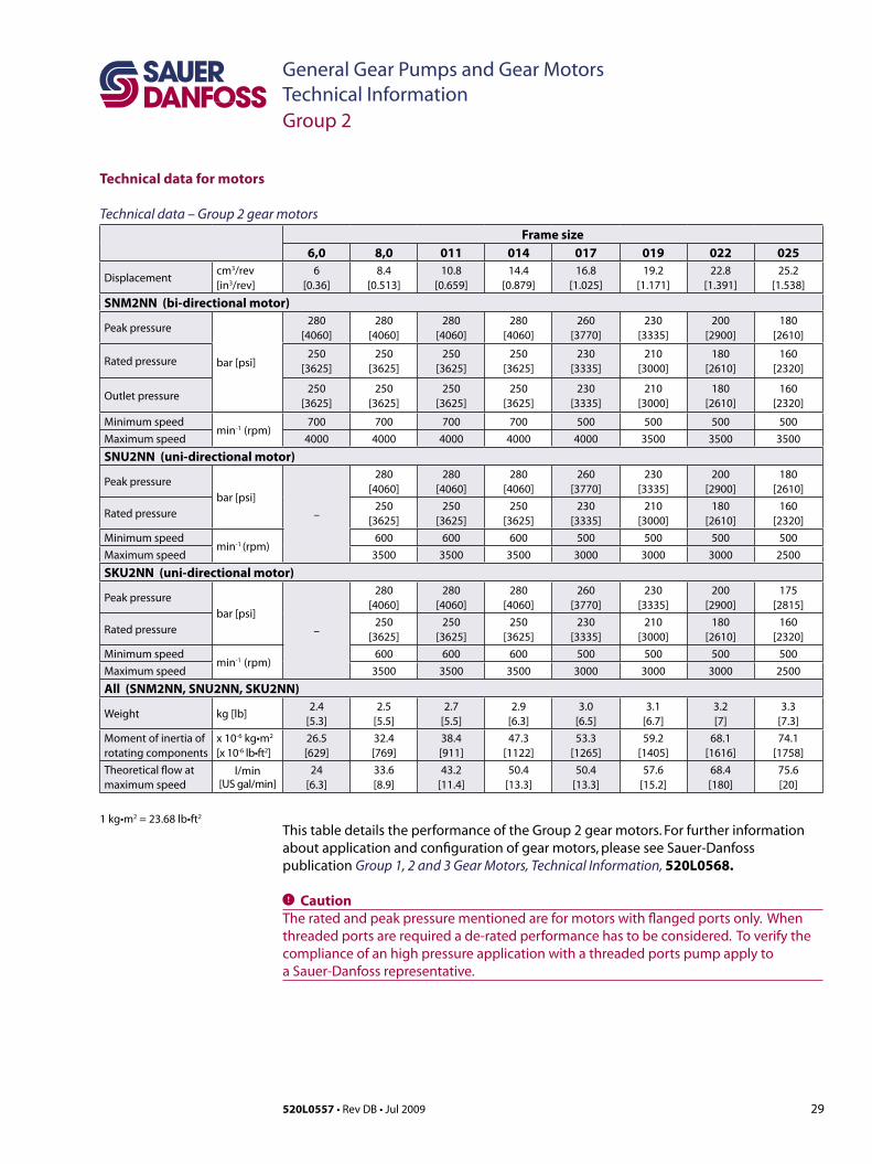
This table details the performance of the Group 2 gear motors. For further information about application and configuration of gear motors, please see Sauer-Danfoss publication Group 1, 2 and 3 Gear Motors, Technical Information, 520L0568.
C CautionTheratedandpeakpressurementionedareformotorswithflangedportsonly.Whenthreaded ports are required a de-rated performance has to be considered. To verify the compliance of an high pressure application with a threaded ports pump apply to a Sauer-Danfoss representative.
30 520L0557 • Rev DB • Jul 2009
General Gear Pumps and Gear MotorsTechnical Information
mm[in]
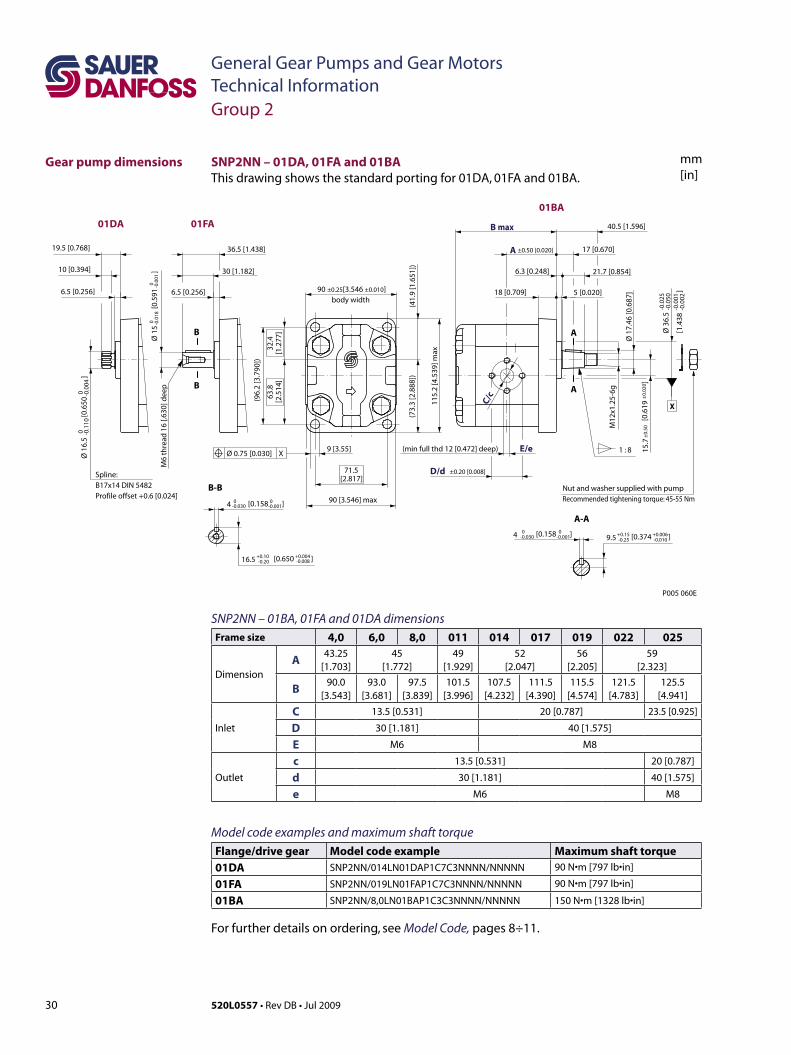
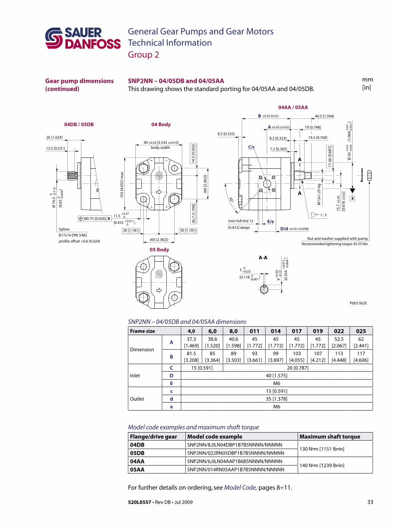
SNP2NN – 01BA, 01FA and 01DA dimensionsFrame size 4,0 6,0 8,0 011 014 017 019 022 025
DimensionA 43.25
[1.703]45
[1.772]49
[1.929]52
[2.047]56
[2.205]59
[2.323]
B 90.0[3.543]
93.0[3.681]
97.5[3.839]
101.5[3.996]
107.5[4.232]
111.5[4.390]
115.5[4.574]
121.5[4.783]
125.5[4.941]
Inlet
C 13.5 [0.531] 20 [0.787] 23.5 [0.925]
D 30 [1.181] 40 [1.575]
E M6 M8
Outlet
c 13.5 [0.531] 20 [0.787]
d 30 [1.181] 40 [1.575]
e M6 M8
Model code examples and maximum shaft torque Flange/drive gear Model code example Maximum shaft torque01DA SNP2NN/014LN01DAP1C7C3NNNN/NNNNN 90 N•m[797 lb•in]
01FA SNP2NN/019LN01FAP1C7C3NNNN/NNNNN 90 N•m[797 lb•in]
01BA SNP2NN/8,0LN01BAP1C3C3NNNN/NNNNN 150 N•m[1328 lb•in]
For further details on ordering, see Model Code, pages 8÷11.
SNP2NN – 01DA, 01FA and 01BAThis drawing shows the standard porting for 01DA, 01FA and 01BA.
[0.374 ]+0.15 +0.006-0.25 -0.010
[1.4
38
]
-0.0
25-0
.050
-0.0
01-0
.002
9 [3.55]
Nut and washer supplied with pumpRecommended tightening torque: 45-55 Nm
[0.6
19
]
A
A
(minfullthd12[0.472]deep) 1 : 8
A-A
M12
x1.2
5-6g
E/e
40.5 [1.596]
6.3 [0.248] 21.7 [0.854]
17 [0.670]
18 [0.709] 5 [0.020]
C/c
M6
thre
ad 1
6 [.6
30] d
eep
B-B
B
B
6.5 [0.256]
30 [1.182]
36.5 [1.438]
Spline:B17x14 DIN 5482Profileoffset+0.6[0.024]
6.5 [0.256]
10 [0.394]
19.5 [0.768]
body width
(96.
2[3
.790
])
115.
2 [4
.539
] max
90 [3.546] max
D/d ±0.20 [0.008]
(41.
9[1
.651
])
71.5[2.817]
63.8
[2.5
14]
32.4
[1.2
77]
(73.
3[2
.888
])
90 ±0.25[3.546 ±0.010]
15.7
±0.
50±
0.02
0
4 0 0-0.030 [0.158 ]-0.001 9.5
Ø 1
6.5
[
0.65
0
]0 -0
.110
0 -0.0
04
Ø 3
6.5
Ø 1
7.46
[0.6
87]
Ø 1
5
[0.5
91
]0 -0
.018
0 -0.0
01
X
Ø 0.75 [0.030] X
01BA
±0.50 [0.020]
P005 060E
B max
A
01FA01DA
[0.650 ]16.5 +0.10-0.20
+0.004-0.008
4 0-0.030
0-0.001[0.158 ]
Group 2
Gear pump dimensions
31520L0557 • Rev DB • Jul 2009
General Gear Pumps and Gear MotorsTechnical Information
mm[in]
3 [0.118 ]
Ø 8
0
[3.1
50
]
9 [0.354]
Ø 1
6.5
[
0.65
0
]
Spline:B17x14 DIN 5482profileoffset+0.6[.024]
13.5 [0.531]
23.5 [0.952]
1 : 5
A
A-A
A
M12
x1.2
5-6g
16.5 [0.650]
E/e
C/c
17.4
6[0
.687
]
38 [1.496]B max
12.5 [0.492] 7.2 [0.283]
5.7 [0.224] 19.3 [0.760]
45°
body width
(100
[3.9
37])
D/d ±0.20 [±0.008]
A
72[2.835]
120
[4.7
24] m
ax
92 [3.622] max
(44.
5[1
.72]
)
65.5
[2.5
79]
34.5
[1.3
58]
(75.
5[2
.972
])
90 ±0.25 [3.543 ±0.010]
0 -0.1
100 -0
.004
-0.0
60-0
.090
-0.0
02-0
.003
0-0.025
0-0.001 9 [0.354 ]+0.30
-0.10+0.012-0.004
15.7
[
0.61
8
]±
0.50
±0.
02
Ø 0.75 [0.030] X
X
(minfullthd12[0.472]deep)
P005 061E
02DB
02AA
±0.50 [±0.02]
Nut and washer supplied with pumpRecommended tightening torque: 45-55 Nm
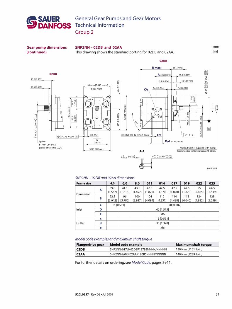
SNP2NN – 02DB and 02AA dimensionsFrame size 4,0 6,0 8,0 011 014 017 019 022 025
Dimension
A39.8
[1.567]41.1
[1.618]43.1
[1.697]47.5
[1.870]47.5
[1.870]47.5
[1.870]47.5
[1.870]55
[2.165]64.5
[2.539]
B92.5
[3.642]96
[3.780]100
[3.937]104
[4.094]110
[4.331]114
[4.488]118
[4.646]124
[4.882]128
[5.039]
Inlet
C 15 [0.591] 20 [0.787]D 40 [1.575]E M6
Outlet
c 15 [0.591]d 35 [1.378]e M6
Model code examples and maximum shaft torque Flange/drive gear Model code example Maximum shaft torque02DB SNP2NN/017LN02DBP1B7B5NNNN/NNNNN 130 N•m[1151 lb•in]
02AA SNP2NN/6,0RN02AAP1B6B5NNNN/NNNNN 140 N•m[1239 lb•in]
For further details on ordering, see Model Code, pages 8÷11.
SNP2NN – 02DB and 02AAThis drawing shows the standard porting for 02DB and 02AA.
Gear pump dimensions (continued)
Group 2
32 520L0557 • Rev DB • Jul 2009
General Gear Pumps and Gear MotorsTechnical Information
mm[in]
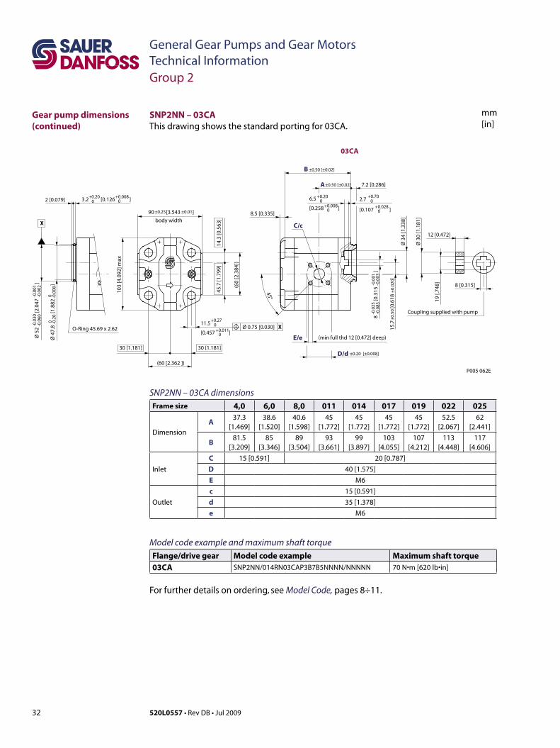
SNP2NN – 03CAThisdrawingshowsthestandardportingfor03CA.
3.2 [0.126 ]+0.200
+0.00802 [0.079]
(min full thd 12 [0.472] deep)
Ø 3
4 [1
.338
]
7.2 [0.286]
19
[.748
]
Ø 3
0 [1
.181
]
12 [0.472]
45°
X
O-Ring 45.69 x 2.62
body width
(60
[2.3
84])
B ±0.50 [±0.02]
A
(60 [2.362 ])
103
[4.0
92] m
ax
Ø 5
2
[2.
047
]
-0.0
30-0
.060
-0.0
01-0
.002
8
[0.
315
]
-0.0
25-0
.083
-0.0
01-0
.003
11.5
[0.457 ]
+0.270+0.011
0
2.7
[0.107 ]
+0.700
+0.0280
6.5
[0.258 ]
+0.200
+0.0080
Ø 4
7.8
[1
.882
]
0 -0.2
00 -0
.008
15.7
[0
.618
]±
0.50
±0.
020
90 [3.543 ]±0.25 ±0.01
Ø 0.75 [0.030] X
8 [0.315]
Coupling supplied with pump
P005 062E
±0.50 [±0.02]
D/d
E/e
C/c
±0.20 [±0.008]
03CA
45.7
[1.7
99]
14.3
[0.5
63]
30 [1.181]30 [1.181]
8.5 [0.335]
SNP2NN – 03CA dimensionsFrame size 4,0 6,0 8,0 011 014 017 019 022 025
Dimension
A37.3
[1.469]38.6
[1.520]40.6
[1.598]45
[1.772]45
[1.772]45
[1.772]45
[1.772]52.5
[2.067]62
[2.441]
B81.5
[3.209]85
[3.346]89
[3.504]93
[3.661]99
[3.897]103
[4.055]107
[4.212]113
[4.448]117
[4.606]
Inlet
C 15 [0.591] 20 [0.787]D 40 [1.575]E M6
Outlet
c 15 [0.591]d 35 [1.378]e M6
Model code example and maximum shaft torque Flange/drive gear Model code example Maximum shaft torque03CA SNP2NN/014RN03CAP3B7B5NNNN/NNNNN 70 N•m[620 lb•in]
For further details on ordering, see Model Code, pages 8÷11.
Gear pump dimensions (continued)
Group 2
33520L0557 • Rev DB • Jul 2009
General Gear Pumps and Gear MotorsTechnical Information
mm[in]
3
[0.118 ]
11.5
[0.453 ]
Ø 1
6.5
[0.6
5
]
A ±0.50 [±0.02]
B
8.5 [0.335]
±0.50 [0.02]
+0.27 0+0.011
0
Spline:
B17x14 DIN 5482
profile offset +0.6 [0.024]
13.5 [0.531]
26 [1.024]
A-A
A
A
1 : 5
X
(min full thd 12
[0.472] deep)
M12
x1.2
5-6g
17.4
6 [0
.687
]
19 [0.748]
E/e
C/c 7.2 [0.283]
40.5 [1.594]
8.2 [0.323] 19.3 [0.760]
45°
body width
(60
[2.3
62])
D/d ±0.20 [±0.008]
90 ±0.50 [3.543 ±0.010]
(60 [2.362])
103
[4.0
55] m
ax
45.7
[1.7
99]
14.3
[0.5
63]
30 [1.181]
Ø0.75 [0.030] X
0 -0.1
100 -0
.004
-0.0
25-0
.064
Ø 5
0
[1
.969
]
-0.0
01-0
.002
5
+0.
30-0
.10
9 [0.3
54
]
+0.
012
-0.0
04
0-0.025
0-0.001
P005 063E
04DB / 05DB 04 Body
05 Body
04AA / 05AA
15.7
±0.
50
[0.6
18 ±
0.02
]
30 [1.181]
Nut and washer supplied with pumpRecommended tightening torque: 45-55 Nm
SNP2NN – 04/05DB and 04/05AA dimensionsFrame size 4,0 6,0 8,0 011 014 017 019 022 025
Dimension
A37.3
[1.469]38.6
[1.520]40.6
[1.598]45
[1.772]45
[1.772]45
[1.772]45
[1.772]52.5
[2.067]62
[2.441]
B81.5
[3.208]85
[3.364]89
[3.503]93
[3.661]99
[3.897]103
[4.055]107
[4.212]113
[4.448]117
[4.606]
Inlet
C 15 [0.591] 20 [0.787]D 40 [1.575]E M6
Outlet
c 15 [0.591]d 35 [1.378]e M6
Model code examples and maximum shaft torque Flange/drive gear Model code example Maximum shaft torque04DB SNP2NN/8,0LN04DBP1B7B5NNNN/NNNNN
130 N•m[1151 lb•in]05DB SNP2NN/022RN05DBP1B7B5NNNN/NNNNN
04AA SNP2NN/6,0LN04AAP1B6B5NNNN/NNNNN140 N•m[1239 lb•in]
05AA SNP2NN/014RN05AAP1B7B5NNNN/NNNNN
For further details on ordering, see Model Code, pages 8÷11.
SNP2NN – 04/05DB and 04/05AAThis drawing shows the standard porting for 04/05AA and 04/05DB.
Gear pump dimensions (continued)
Group 2
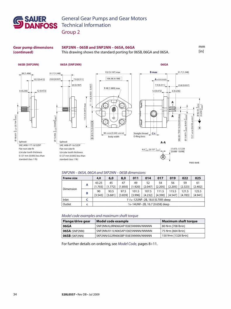
34 520L0557 • Rev DB • Jul 2009
General Gear Pumps and Gear MotorsTechnical Information
mm[in]
SKP2NN – 06SB and SNP2NN – 06SA, 06GA This drawing shows the standard porting for 06SB, 06GA and 06SA.
SNP2NN – 06SA, 06GA and SKP2NN – 06SB dimensionsFrame size 4,0 6,0 8,0 011 014 017 019 022 025
Dimension
A43.25
[1.703]45
[1.772]47
[1.850]49
[1.920]52
[2.047]54
[2.205]56
[2.205]59
[2.323]61
[2.402]
B90
[3.543]93.5
[3.681]97.5
[3.839]101.5
[3.996]107.5
[4.232]111.5
[4.390]115.5
[4.547]121.5
[4.783]125.5
[4.941]Inlet C 11/ 16–12UNF–2B, 18.0 [0.709] deepOutlet c 7/ 8–14UNF–2B, 16.7 [0.658] deep
Model code examples and maximum shaft torque Flange/drive gear Model code example Maximum shaft torque06GA SNP2NN/6,0RN06GAP1E6E5NNNN/NNNNN 80 N•m[708 lb•in]
06SA (SNP2NN) SNP2NN/011LN06SAP1E6E5NNNN/NNNNN 75 N•m [664 lb•in]
06SB (SKP2NN) SKP2NN/022RN06SBP1E6E5NNNN/NNNNN 150 N•m[1328 lb•in]
For further details on ordering, see Model Code, pages 8÷11.
A
A
A-A
7.9 [0.311] 23.8 [0.937]
B max 31.7 [1.248]
C/c
M6-
6H-T
HD
16
[0.6
30]d
eep
17.475 -17.729[0.688 - 0.698]
12 [0.472] 6 [0.236]
body width
11 -
11.6
[0.4
33 -
0.45
7]
A ±0.50 [0.020]
132 [5.197] max
106.38 [4.188]
115.
5 [4
.547
] max
Ø 8
2.55
[3.2
50
]
0 -0.0
500 -0
.020
4.0 [0.157 ]0-0.03
0-0.001
Ø 1
5.87
5
[0.
625
]
0 -0.0
250 -0
.010
15.7
±0.
50 [0
.618
±0.
020
]
Ø 0
.75
[0.0
30] X
X
Straight thread O-Ringboss
P005 064E
06SA (SNP2NN)
12 [0.472]6 [0.236]
Splined:
SAE J498-11T-16/32DP
Flat root side fit
(circulartooththickness
0.127 mm [0.005] less than
standard class 1 fit)
38 [1.496]
10.5 [0.413]
Ø 1
8.63
1
[0.
734
]
0 -0.1
270 -0
.005
06SB (SKP2NN) 06GA
20 [0.787]
31.7 [1.248]
23.8 [0.937] 7.9 [0.311]
Ø 1
5.45
6
[0.
609
]
0 -0.1
270 -0
.005
90 ±0.50 [3.543 ±0.010]
R 48 [1.889] max
Splined:
SAE J498-9T-16/32DP
Flat root side fit
(circulartooththickness
0.127 mm [0.005] less than
standard class 1 fit)
Gear pump dimensions (continued)
Group 2
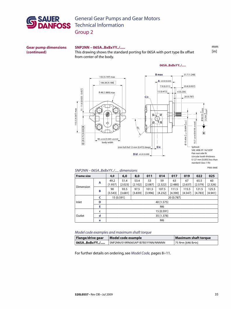
35520L0557 • Rev DB • Jul 2009
General Gear Pumps and Gear MotorsTechnical Information
mm[in]
SNP2NN – 06SA..BxBxYY../..... dimensionsFrame size 4,0 6,0 8,0 011 014 017 019 022 025
Dimension
A49.2
[1.937]51.4
[2.023]53.4
[2.102]53
[2.087]59
[2.322]63
[2.480]67
[2.637]65.5
[2.579]60
[2.326]
B90
[3.543]93.5
[3.681]97.5
[3.839]101.5
[3.996]107.5
[4.232]111.5
[4.390]115.5
[4.547]121.5
[4.783]125.5
[4.941]
Inlet
C 15 [0.591] 20 [0.787]D 40 [1.575]E M6
Outlet
c 15 [0.591]d 35 [1.378]e M6
Model code examples and maximum shaft torque Flange/drive gear Model code example Maximum shaft torque06SA..BxBxYY../..... SNP2NN/019RN06SAP1B7B5YYNN/NNNNN 75 N•m[646 lb•in]
For further details on ordering, see Model Code, pages 8÷11.
X
P005 066E
20 [0.787] 45°
E/e
C/c
B max
D/d
A
06SA..BxBxYY../.....
7.9 [0.311] 23.8 [0.937]
31.7 [1.248]
12 [0.472] 6 [0.236]
11 -
11.6
[0.4
33 -
0.45
7]
±0.50 [0.020]
132 [5.197] max
106.38 [4.188]
115.
5 [4
.547
] max
Ø 8
2.55
[3.2
50
]
0 -0.0
50
0 -0.0
20
Ø 0
.75
[0.0
30] X
Splined: SAE J498-9T-16/32DP Flat root side fit (circular tooth thickness 0.127 mm [0.005] less than standard class 1 fit)
body width
90 ±0.50 [3.543 ±0.010]
(min full thd 12 mm [0.472] deep)
±0.20 [0.008]
R 48 [1.889] max
Ø 1
5.45
6
[0.6
09
] 0 -0
.127
0 -0
.005
15.7
±0.
50 [0
.618
±0.
020 ]
SNP2NN – 06SA..BxBxYY../.....This drawing shows the standard porting for 06SA with port type Bx offset from center of the body.
Gear pump dimensions (continued)
Group 2
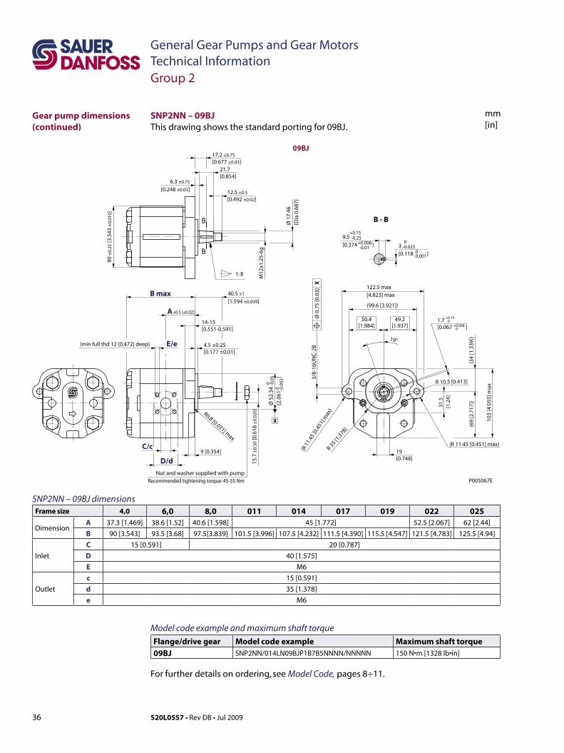
36 520L0557 • Rev DB • Jul 2009
General Gear Pumps and Gear MotorsTechnical Information
mm[in]
1.7 [0.067 ]
1: 8
B
B B - BØ 1
7.46
[D
ia 0
.687
]
M12
x1.2
5-6g
21.7 [0.854]
14-15 [0.551-0.591]
9 [0.354]
R 10.5 [0.413]
19°
31.5
[1.2
4]
3/8-
16U
NC
-2B
122.5 max[4.823] max
(99.6[3.921])
103
[4.0
55] m
ax
(69
[2.7
17])
(34
[1.3
39])
19 [0.748]
P005067E
(R11.45[0.451]max)
(R1
1.45
[0.4
51]m
ax)
R 35 [1
.378]
49.2[1.937]
50.4[1.984]
17.2 ±0.75
[0.677 ±0.03]
40.5 [1.594 ±0.039]
±1
90 ±
0.25
[3.5
43 ±
0.01
0]
12.5 ±0.5
[0.492 ±0.02]
6.3 ±0.75
[0.248 ±0.03]
15.7
±0.
50 [0
.618
±0.
020]
4.5 ±0.25 [0.177 ±0.01]
9.5 [0.374 ]
+0.15
+0.006-0.25
-0.01
+0.15
+0.0060
0
3 [0.118 ]
0
0-0.025
-0.001
Ø 5
2.34
[2.0
61
]
0
0-0
.05
-0.0
02
Ø 0
.75
[0.0
3]
X
X
(minfullthd12[0.472]deep)
B max
A
C/c
E/e
D/d
±0.5 [±0.02]
09BJ
R0.8 [0.031] max
Nut and washer supplied with pumpRecommended tightening torque: 45-55 Nm
SNP2NN – 09BJ dimensionsFrame size 4,0 6,0 8,0 011 014 017 019 022 025
DimensionA 37.3 [1.469] 38.6 [1.52] 40.6 [1.598] 45 [1.772] 52.5 [2.067] 62 [2.44]B 90 [3.543] 93.5 [3.68] 97.5[3.839] 101.5 [3.996] 107.5 [4.232] 111.5 [4.390] 115.5 [4.547] 121.5 [4.783] 125.5 [4.94]
Inlet
C 15 [0.591] 20 [0.787]D 40 [1.575]E M6
Outlet
c 15 [0.591]d 35 [1.378]e M6
SNP2NN – 09BJThis drawing shows the standard porting for 09BJ.
Gear pump dimensions (continued)
Group 2
Model code example and maximum shaft torque Flange/drive gear Model code example Maximum shaft torque09BJ SNP2NN/014LN09BJP1B7B5NNNN/NNNNN 150 N•m[1328 lb•in]
For further details on ordering, see Model Code, pages 8÷11.
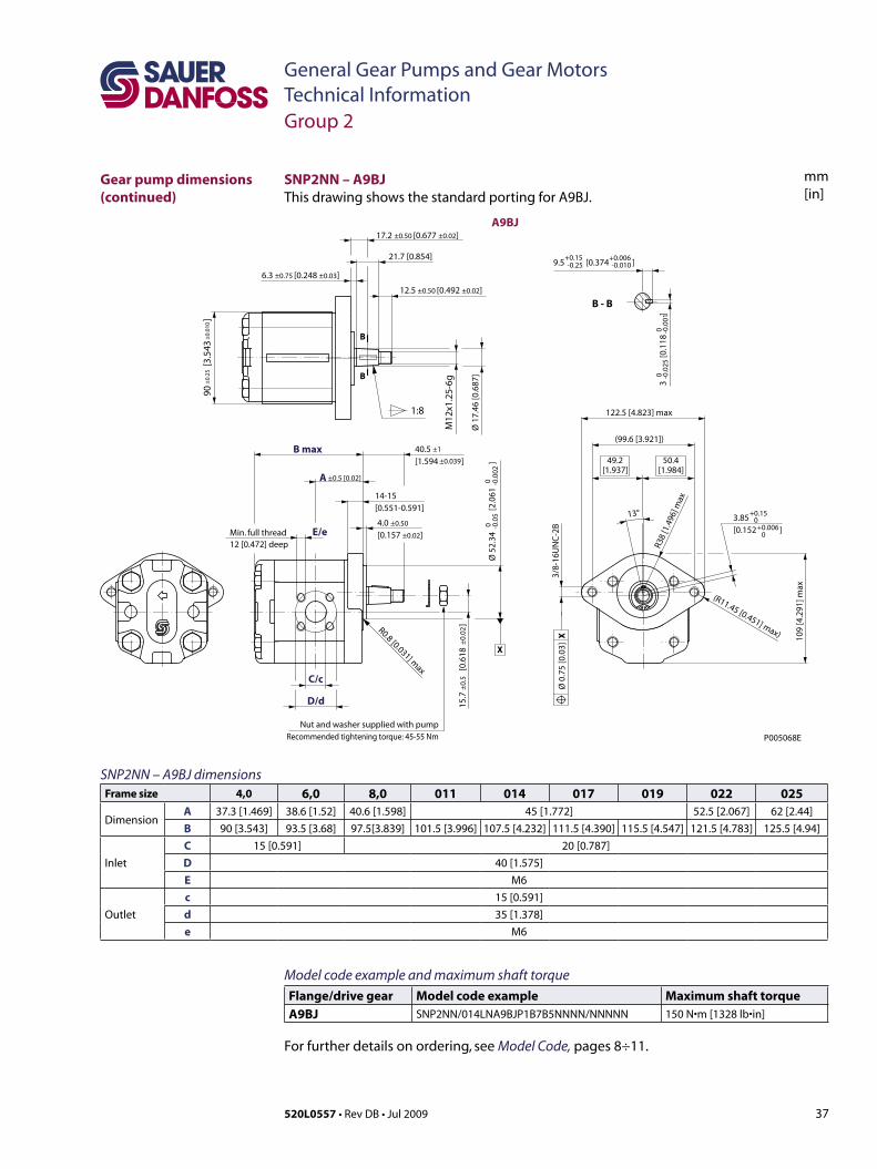
37520L0557 • Rev DB • Jul 2009
General Gear Pumps and Gear MotorsTechnical Information
mm[in]
SNP2NN – A9BJ dimensionsFrame size 4,0 6,0 8,0 011 014 017 019 022 025
DimensionA 37.3 [1.469] 38.6 [1.52] 40.6 [1.598] 45 [1.772] 52.5 [2.067] 62 [2.44]B 90 [3.543] 93.5 [3.68] 97.5[3.839] 101.5 [3.996] 107.5 [4.232] 111.5 [4.390] 115.5 [4.547] 121.5 [4.783] 125.5 [4.94]
Inlet
C 15 [0.591] 20 [0.787]D 40 [1.575]E M6
Outlet
c 15 [0.591]d 35 [1.378]e M6
1:8
B
B
B - B
21.7 [0.854]
M12
x1.2
5-6g
Ø 1
7.46
[0.6
87]
3
[0.
118
]
00
-0.0
25-0
.001
9.5 [0.374 ]+0.15 +0.006-0.25 -0.010
90
[3.5
43
]±
0.25
±0.
010
R0.8 [0.031] max
14-15 [0.551-0.591]
3/8-
16U
NC
-2B
(99.6[3.921])
122.5 [4.823] max
109
[4.2
91] m
ax
R38
[1.4
96] m
ax
(R11.45[0.451]max)
13°
50.4[1.984]
49.2[1.937]
3.85 [0.152 ]
+0.15
+0.0060
0
Ø 5
2.34
[
2.06
1
]0
0-0
.05
-0.0
02
15.7
[
0.61
8
]±
0.5
±0.
02
40.5 [1.594 ]
±1
±0.039
X
Ø 0
.75
[0.0
3] X
Min. full thread12 [0.472] deep
E/e
C/c
D/d
B max
A
A9BJ
±0.5 [0.02]
4.0 ±0.50
[0.157 ±0.02]
17.2 ±0.50 [0.677 ±0.02]
6.3 ±0.75 [0.248 ±0.03]
12.5 ±0.50 [0.492 ±0.02]
Nut and washer supplied with pumpRecommended tightening torque: 45-55 Nm P005068E
SNP2NN – A9BJThis drawing shows the standard porting for A9BJ.
Gear pump dimensions (continued)
Group 2
Model code example and maximum shaft torque Flange/drive gear Model code example Maximum shaft torqueA9BJ SNP2NN/014LNA9BJP1B7B5NNNN/NNNNN 150 N•m[1328 lb•in]
For further details on ordering, see Model Code, pages 8÷11.
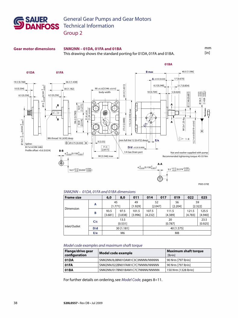
38 520L0557 • Rev DB • Jul 2009
General Gear Pumps and Gear MotorsTechnical Information
mm[in]
[1.4
38
]
-0.0
25-0
.050
-0.0
01-0
.002
9 [3.55]
[0.6
19
]A
A
[0.650 ]
(min full thd 12 [0.472] deep) 1 : 8
A-A
M12
x1.2
5-6g
E/e
40.5 [1.596]
6.3 [0.248] 21.7 [0.854]
17 [0.670]
18 [0.709] 5 [0.020]
C/c
M6 thread 16 [.630] deep
B-B
B
B
6.5 [0.256]
30 [1.182]
36.5 [1.438]
Spline:B17x14 DIN 5482Profile offset +0.6 [0.024]
6.5 [0.256]
10 [0.394]
19.5 [0.768]
body width
(96.
2 [3
.790
])
115.
2 [4
.539
] max
90 [3.546] max
D/d ±0.20 [0.008]
(41.
9 [1
.651
])
71.5[2.817]
63.8
[2.5
14]
32.4
[1.2
77]
(73.
3 [2
.888
])
90 ±0.25[3.546 ±0.010]
15.7
±0.
50±
0.02
0
Ø 1
6.5
[
0.65
0
]0 -0
.110
0 -0.0
04
Ø 3
6.5
Ø 1
7.46
[0.6
87]
16.5+0.10-0.20
+0.004 -0.008
[0.374 ]9.5 +0.15-0.25
+0.006 -0.010
Ø15
[
0.59
1
]0 -0
.018
0 -0.0
01
4 0-0.030
0-0.001[0.158 ]
4 0-0.030
0-0.001[0.158 ]
X
Ø 0.75 [0.030] X
01BA
±0.50 [0.020]
P005 070E
B max
A
01FA01DA
1/4 Gas Drain port
31.4
±0.
50
[1.2
4 ±
0.02
0]
Nut and washer supplied with pump
Recommended tightening torque: 45-55 Nm
SNM2NN – 01DA, 01FA and 01BA dimensionsFrame size 6,0 8,0 011 014 017 019 022 025
Dimension
A45
[1.771]49
[1.929]52
[2.047]56
[2.204]59
[2.322]
B93.5
[3.681]97.5
[3.838]101.5
[3.996]107.5
[4.232]111.5
[4.389]121.5
[4.783]125.5
[4.940]
Inlet/Outlet
C/c13.5
[0.531]20
[0.787]23.5
[0.925]D/d 30 [1.181] 40 [1.575]E/e M6 M8
Model code examples and maximum shaft torque Flange/drive gear configuration Model code example Maximum shaft torque
[lb•in]
01DA SNM2NN/8,0BN01DAM1C3C3NNNN/NNNNN 90 N•m[797 lb•in]
01FA SNM2NN/022BN01FAM1C7C7NNNN/NNNNN 90 N•m[797 lb•in]
01BA SNM2NN/017BN01BAM1C7C7NNNN/NNNNN 150 N•m[1328 lb•in]
For further details on ordering, see Model Code, pages 8÷11.
SNM2NN – 01DA, 01FA and 01BAThis drawing shows the standard porting for 01DA, 01FA and 01BA.
Group 2
Gear motor dimensions
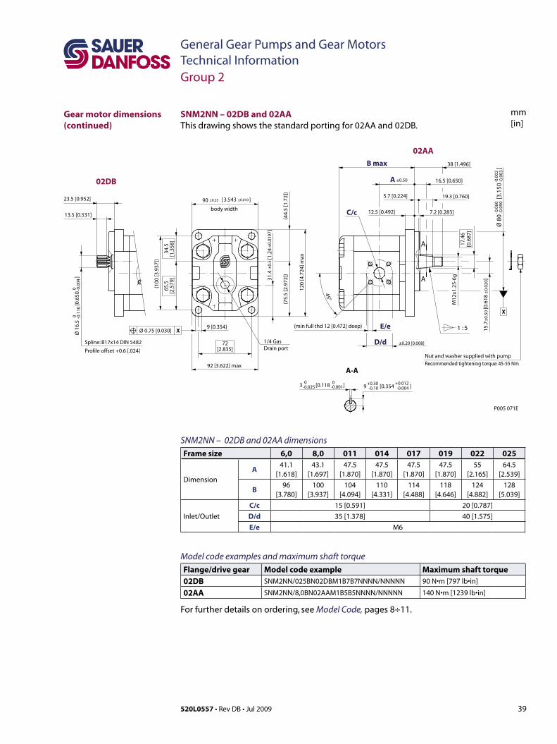
39520L0557 • Rev DB • Jul 2009
General Gear Pumps and Gear MotorsTechnical Information
mm[in]
SNM2NN – 02DB and 02AA dimensionsFrame size 6,0 8,0 011 014 017 019 022 025
Dimension
A41.1
[1.618]43.1
[1.697]47.5
[1.870]47.5
[1.870]47.5
[1.870]47.5
[1.870]55
[2.165]64.5
[2.539]
B96
[3.780]100
[3.937]104
[4.094]110
[4.331]114
[4.488]118
[4.646]124
[4.882]128
[5.039]
Inlet/Outlet
C/c 15 [0.591] 20 [0.787]D/d 35 [1.378] 40 [1.575]E/e M6
Model code examples and maximum shaft torque Flange/drive gear Model code example Maximum shaft torque02DB SNM2NN/025BN02DBM1B7B7NNNN/NNNNN 90 N•m[797 lb•in]
02AA SNM2NN/8,0BN02AAM1B5B5NNNN/NNNNN 140 N•m[1239 lb•in]
For further details on ordering, see Model Code, pages 8÷11.
3 [0.118 ]
Ø 8
0
[3.1
50
]
9 [0.354]
Ø 1
6.5
[
0.65
0
]
Spline: B17x14 DIN 5482
Profile offset +0.6 [.024]
13.5 [0.531]
23.5 [0.952]
1 : 5
A
A-A
A
M12
x1.2
5-6g
16.5 [0.650]
E/e
17.4
6[0
.687
]
38 [1.496]B max
12.5 [0.492] 7.2 [0.283]
5.7 [0.224] 19.3 [0.760]
C/c
45°
body width
(100
[3.9
37])
D/d ±0.20 [0.008]
A ±0.50
72[2.835]
120
[4.7
24] m
ax
92 [3.622] max
(44.
5 [1
.72]
)
65.5
[2.5
79]
34.5
[1.3
58]
(75.
5 [2
.972
])
90 ±0.25 ±0.0103.543[ ]
0 -0.1
100 -0
.004
-0.0
60-0
.090
-0.0
02-0
.003
0-0.025
0-0.001 9 [0.354 ]
+0.30-0.10
+0.012-0.004
15.7
±0.
50 [0
.618
±0.
020]
Ø 0.75 [0.030] X
X
(min full thd 12 [0.472] deep)
02DB
02AA
1/4 GasDrain port
31.4
[1
.24
]±
0.5
±0.
0197
P005 071E
Nut and washer supplied with pumpRecommended tightening torque: 45-55 Nm
SNM2NN – 02DB and 02AA This drawing shows the standard porting for 02AA and 02DB.
Group 2
Gear motor dimensions (continued)
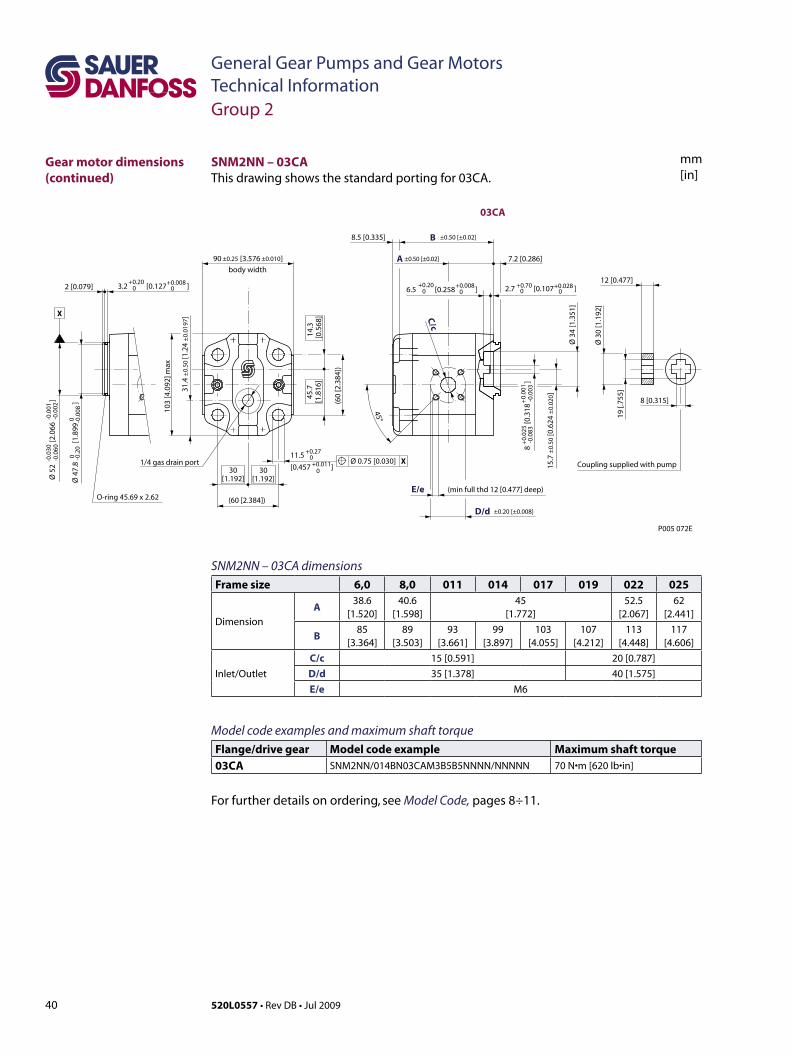
40 520L0557 • Rev DB • Jul 2009
General Gear Pumps and Gear MotorsTechnical Information
mm[in]
SNM2NN – 03CA dimensionsFrame size 6,0 8,0 011 014 017 019 022 025
Dimension
A38.6
[1.520]40.6
[1.598]45
[1.772]52.5
[2.067]62
[2.441]
B85
[3.364]89
[3.503]93
[3.661]99
[3.897]103
[4.055]107
[4.212]113
[4.448]117
[4.606]
Inlet/Outlet
C/c 15 [0.591] 20 [0.787]D/d 35 [1.378] 40 [1.575]E/e M6
Model code examples and maximum shaft torque Flange/drive gear Model code example Maximum shaft torque03CA SNM2NN/014BN03CAM3B5B5NNNN/NNNNN 70 N•m[620 lb•in]
For further details on ordering, see Model Code, pages 8÷11.
3.2 [0.127 ]+0.20
0+0.008
02 [0.079]
(minfullthd12[0.477]deep)E/e
Ø 3
4 [1
.351
]
7.2 [0.286]
19 [.
755]
Ø 3
0 [1
.192
]
12 [0.477]
C/c
45°
X
O-ring45.69x2.62
body width
(60
[2.3
84])
D/d ±0.20 [±0.008]
B8.5 [0.335] ±0.50 [±0.02]
A
(60[2.384])
103
[4.0
92] m
ax
30[1.192]
45.7
[1.8
16]
14.3
[0.5
68]
30[1.192]Ø
52
[2.0
66
]
-0.0
30-0
.060
-0.0
01-0
.002
8
[0
.318
]+
0.02
5-0
.083
+0.
001
-0.0
03
11.5
[0.457 ]
+0.270+0.011
0
2.7 [0.107 ]+0.700
+0.02806.5 [0.258 ]
+0.200
+0.0080
Ø 4
7.8
[1
.899
]
0 -0.2
00 -0
.008
15.7
±0.
50 [0
.624
±0.
020]
90 [3.576 ]±0.25 ±0.010
Ø 0.75 [0.030] X
8 [0.315]
Coupling supplied with pump
±0.50 [±0.02]
1/4 gas drain port
31.4
±0.
50 [1
.24
±0.
0197
]
P005 072E
03CA
SNM2NN – 03CAThisdrawingshowsthestandardportingfor03CA.
Group 2
Gear motor dimensions (continued)
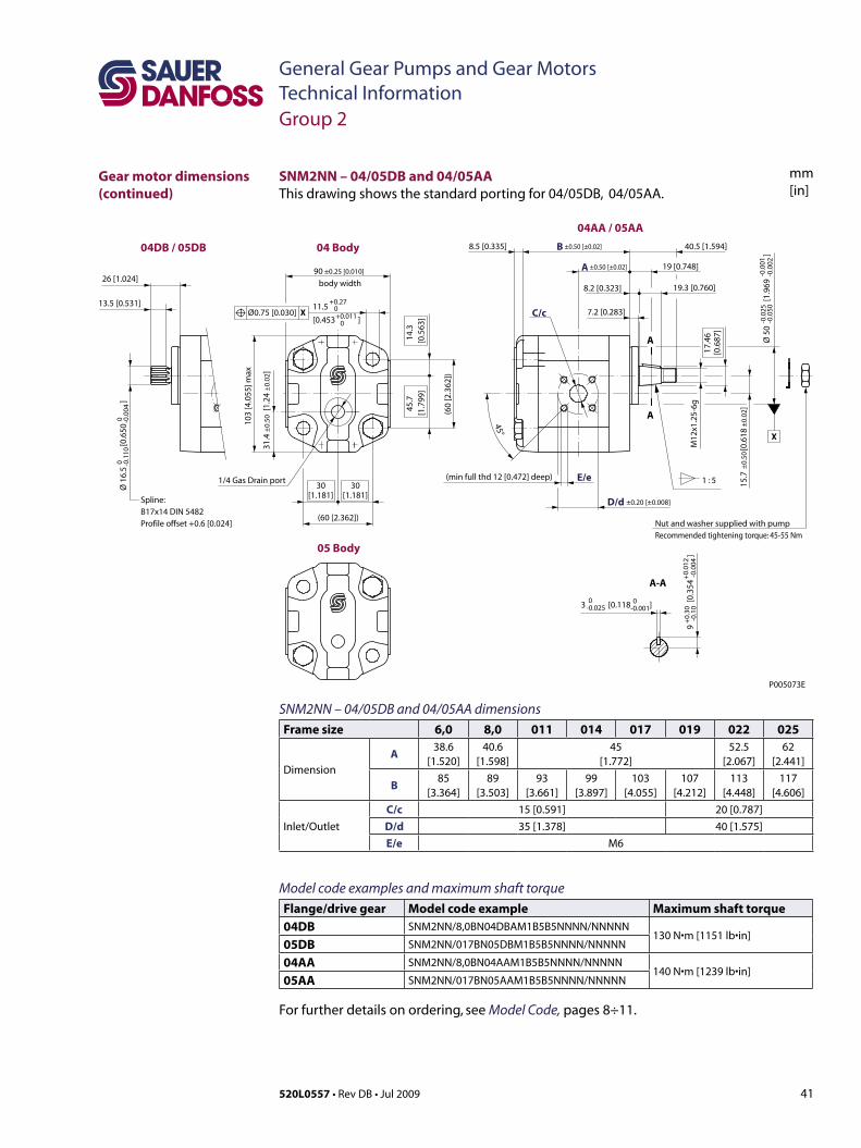
41520L0557 • Rev DB • Jul 2009
General Gear Pumps and Gear MotorsTechnical Information
mm[in]
SNM2NN – 04/05DB and 04/05AA dimensionsFrame size 6,0 8,0 011 014 017 019 022 025
Dimension
A38.6
[1.520]40.6
[1.598]45
[1.772]52.5
[2.067]62
[2.441]
B85
[3.364]89
[3.503]93
[3.661]99
[3.897]103
[4.055]107
[4.212]113
[4.448]117
[4.606]
Inlet/Outlet
C/c 15 [0.591] 20 [0.787]D/d 35 [1.378] 40 [1.575]E/e M6
Model code examples and maximum shaft torque Flange/drive gear Model code example Maximum shaft torque04DB SNM2NN/8,0BN04DBAM1B5B5NNNN/NNNNN
130 N•m[1151 lb•in]05DB SNM2NN/017BN05DBM1B5B5NNNN/NNNNN
04AA SNM2NN/8,0BN04AAM1B5B5NNNN/NNNNN140 N•m[1239 lb•in]
05AA SNM2NN/017BN05AAM1B5B5NNNN/NNNNN
For further details on ordering, see Model Code, pages 8÷11.
3 [0.118 ]
11.5
[0.453 ]
Ø 1
6.5
[0
.650
]
±0.
50±
0.02
A
B8.5 [0.335]
±0.50 [±0.02]
±0.50 [±0.02]
+0.270+0.011
0
Spline: B17x14 DIN 5482Profile offset +0.6 [0.024]
13.5 [0.531]
26 [1.024]
A-A
A
A
1 : 5
X
(min full thd 12 [0.472] deep)
M12
x1.2
5-6g
17.4
6[0
.687
]
19 [0.748]
E/e
C/c 7.2 [0.283]
40.5 [1.594]
8.2 [0.323] 19.3 [0.760]
45°
body width
(60
[2.3
62])
D/d ±0.20 [±0.008]
90 ±0.25 [0.010]
(60 [2.362])
103
[4.0
55] m
ax
45.7
[1.7
99]
14.3
[0.5
63]
30[1.181]
30[1.181]
Ø0.75 [0.030] X
0 -0.1
100 -0
.004
-0.0
25-0
.050
Ø 5
0
[1
.969
]-0
.001
-0.0
02
+0.
30-0
.10
9
[0.
354
]
+0.
012
-0.0
04
0-0.025
0-0.001
04DB / 05DB 04 Body
05 Body
04AA / 05AA
15.7
[
0.61
8
]
1/4 Gas Drain port
31.4
±0.
50 [
1.24
±0.
02]
Nut and washer supplied with pumpRecommended tightening torque: 45-55 Nm
P005073E
SNM2NN – 04/05DB and 04/05AAThis drawing shows the standard porting for 04/05DB, 04/05AA.
Group 2
Gear motor dimensions (continued)

42 520L0557 • Rev DB • Jul 2009
General Gear Pumps and Gear MotorsTechnical Information
mm[in]
A
A
A-A
7.9 [0.311] 23.8 [0.937]
B max 31.7
[1.248]
C/c
17.475 -17.729[0.688 - 0.698]
12 [0.472] 6 [0.236]
body width
11 -
11.6
[0.4
33 -
0.45
7]
A ±0.50 [0.020]
132 [5.197] max
106.38 [4.188]
115.
5 [4
.547
] max
R 48 [1.889] max
3.995 [0.157 ]0-0.025
0-0.010
90±0.25 [3.543±0.010]
Ø 0
.75
[0.0
30] X
X
P005 074E
06GA
Splined SAE J498-9T-16/32DP flatrootsidefit(circulartooththickness 0.127 [0.005] less than standard class 1 fit)
06SA
20 [0.787]
31.7 [1.248]
23.8[0.937]
7.9 [0.311]
Ø 1
5.45
6
[0.6
09
]0 -0
.127
0 -0.0
05
9/16-18UNF-2BStraight thread O-ringboss
Straight thread O-ringboss
31.4
±0.
5 [1
.24
±0.
02]
M6-
6H-T
HD
16m
m[0
.630
]dee
p
Ø 8
2.55
[3
.250
]
00 -0
.020
Ø 1
5.87
5
[0.
625
]
0 -0.0
250 -0
.010
15.7
±0.
50 [0
.618
±0.
020
]
-0.5
0
SNM2NN – 06GA and 06SA dimensionsFrame size 6,0 8,0 011 014 017 019 022 025
Dimension
A45
[1.772]47
[1.85]49
[1.92]52
[2.047]54
[2.205]56
[2.205]59
[2.323]61
[2.402]
B93.5
[3.681]97.5
[3.839]101.5
[3.996]107.5
[4.232]111.5
[4.390]115.5
[4.547]121.5
[4.783]125.5
[4.941]
Inlet/Outlet C/c 7/ 8–14UNF–2B, 16.7 [0.658] deep1 1/ 16–12UNF–2B, 18 [0.709] deep
Model code examples and maximum shaft torque Flange/drive gear Model code example Maximum shaft torque06GA SNM2NN/017BN06GAM6E5E5NNNN/NNNNN 80 N•m[708 lb•in]
06SA SNM2NN/8,0BN06SAM1E5E5NNNN/NNNNN 75 N•m[664 lb•in]
For further details on ordering, see Model Code, pages 8÷11.
SNM2NN – 06GA and 06SAThis drawing shows the standard porting for 06GA and 06SA.
Group 2
Gear motor dimensions (continued)
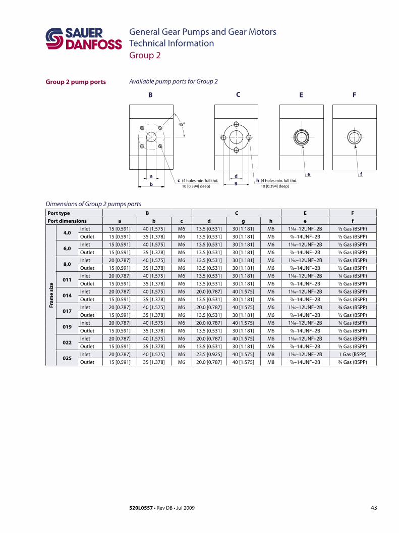
43520L0557 • Rev DB • Jul 2009
General Gear Pumps and Gear MotorsTechnical Information
Group 2 pump ports
Group 2
Dimensions of Group 2 pumps portsPort type B C E FPort dimensions a b c d g h e f
Fram
e si
ze
4,0Inlet 15 [0.591] 40 [1.575] M6 13.5 [0.531] 30 [1.181] M6 11⁄16–12UNF–2B ½ Gas (BSPP)Outlet 15 [0.591] 35 [1.378] M6 13.5 [0.531] 30 [1.181] M6 7⁄8–14UNF–2B ½ Gas (BSPP)
6,0Inlet 15 [0.591] 40 [1.575] M6 13.5 [0.531] 30 [1.181] M6 11⁄16–12UNF–2B ½ Gas (BSPP)Outlet 15 [0.591] 35 [1.378] M6 13.5 [0.531] 30 [1.181] M6 7⁄8–14UNF–2B ½ Gas (BSPP)
8,0Inlet 20 [0.787] 40 [1.575] M6 13.5 [0.531] 30 [1.181] M6 11⁄16–12UNF–2B ½ Gas (BSPP)Outlet 15 [0.591] 35 [1.378] M6 13.5 [0.531] 30 [1.181] M6 7⁄8–14UNF–2B ½ Gas (BSPP)
011Inlet 20 [0.787] 40 [1.575] M6 13.5 [0.531] 30 [1.181] M6 11⁄16–12UNF–2B ¾ Gas (BSPP)Outlet 15 [0.591] 35 [1.378] M6 13.5 [0.531] 30 [1.181] M6 7⁄8–14UNF–2B ½ Gas (BSPP)
014Inlet 20 [0.787] 40 [1.575] M6 20.0 [0.787] 40 [1.575] M6 11⁄16–12UNF–2B ¾ Gas (BSPP)Outlet 15 [0.591] 35 [1.378] M6 13.5 [0.531] 30 [1.181] M6 7⁄8–14UNF–2B ½ Gas (BSPP)
017Inlet 20 [0.787] 40 [1.575] M6 20.0 [0.787] 40 [1.575] M6 11⁄16–12UNF–2B ¾ Gas (BSPP)Outlet 15 [0.591] 35 [1.378] M6 13.5 [0.531] 30 [1.181] M6 7⁄8–14UNF–2B ½ Gas (BSPP)
019Inlet 20 [0.787] 40 [1.575] M6 20.0 [0.787] 40 [1.575] M6 11⁄16–12UNF–2B ¾ Gas (BSPP)Outlet 15 [0.591] 35 [1.378] M6 13.5 [0.531] 30 [1.181] M6 7⁄8–14UNF–2B ½ Gas (BSPP)
022Inlet 20 [0.787] 40 [1.575] M6 20.0 [0.787] 40 [1.575] M6 11⁄16–12UNF–2B ¾ Gas (BSPP)Outlet 15 [0.591] 35 [1.378] M6 13.5 [0.531] 30 [1.181] M6 7⁄8–14UNF–2B ½ Gas (BSPP)
025Inlet 20 [0.787] 40 [1.575] M6 23.5 [0.925] 40 [1.575] M8 11⁄16–12UNF–2B 1 Gas (BSPP)Outlet 15 [0.591] 35 [1.378] M6 20.0 [0.787] 40 [1.575] M8 7⁄8–14UNF–2B ¾ Gas (BSPP)
b
B C FE
ca
(4holesmin. full thd.10 [0.394] deep)
fhg
45o
(4holesmin. full thd.10 [0.394] deep)
ed
Available pump ports for Group 2
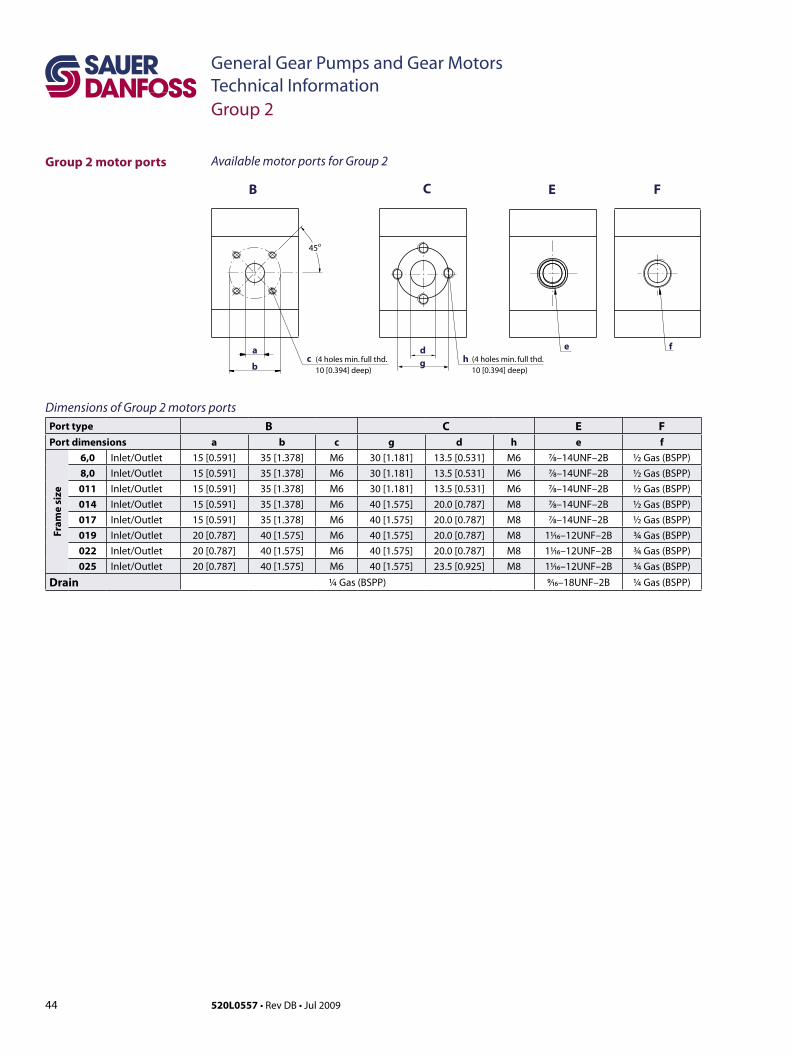
44 520L0557 • Rev DB • Jul 2009
General Gear Pumps and Gear MotorsTechnical Information
Group 2 motor ports
Group 2
b
B C FE
ca
(4holesmin. full thd.10 [0.394] deep)
fhg
45o
(4holesmin. full thd.10 [0.394] deep)
ed
Dimensions of Group 2 motors portsPort type B C E FPort dimensions a b c g d h e f
Fram
e si
ze
6,0 Inlet/Outlet 15 [0.591] 35 [1.378] M6 30 [1.181] 13.5 [0.531] M6 7⁄8–14UNF–2B ½ Gas (BSPP)8,0 Inlet/Outlet 15 [0.591] 35 [1.378] M6 30 [1.181] 13.5 [0.531] M6 7⁄8–14UNF–2B ½ Gas (BSPP)011 Inlet/Outlet 15 [0.591] 35 [1.378] M6 30 [1.181] 13.5 [0.531] M6 7⁄8–14UNF–2B ½ Gas (BSPP)014 Inlet/Outlet 15 [0.591] 35 [1.378] M6 40 [1.575] 20.0 [0.787] M8 7⁄8–14UNF–2B ½ Gas (BSPP)017 Inlet/Outlet 15 [0.591] 35 [1.378] M6 40 [1.575] 20.0 [0.787] M8 7⁄8–14UNF–2B ½ Gas (BSPP)019 Inlet/Outlet 20 [0.787] 40 [1.575] M6 40 [1.575] 20.0 [0.787] M8 11⁄16–12UNF–2B ¾ Gas (BSPP)022 Inlet/Outlet 20 [0.787] 40 [1.575] M6 40 [1.575] 20.0 [0.787] M8 11⁄16–12UNF–2B ¾ Gas (BSPP)025 Inlet/Outlet 20 [0.787] 40 [1.575] M6 40 [1.575] 23.5 [0.925] M8 11⁄16–12UNF–2B ¾ Gas (BSPP)
Drain ¼ Gas (BSPP) 9⁄16–18UNF–2B ¼ Gas (BSPP)
Available motor ports for Group 2
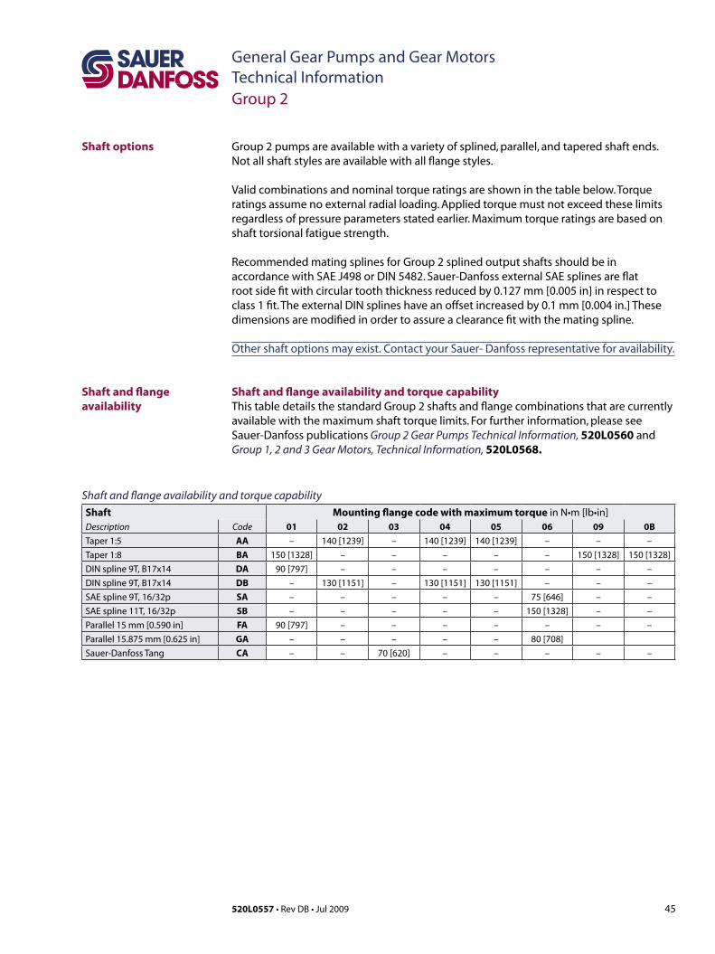
45520L0557 • Rev DB • Jul 2009
General Gear Pumps and Gear MotorsTechnical Information
Group 2 pumps are available with a variety of splined, parallel, and tapered shaft ends. Not all shaft styles are available with all flange styles.
Valid combinations and nominal torque ratings are shown in the table below. Torque ratings assume no external radial loading. Applied torque must not exceed these limits regardless of pressure parameters stated earlier. Maximum torque ratings are based on shaft torsional fatigue strength.
Recommended mating splines for Group 2 splined output shafts should be in accordance with SAE J498 or DIN 5482. Sauer-Danfoss external SAE splines are flat root side fit with circular tooth thickness reduced by 0.127 mm [0.005 in] in respect to class 1 fit. The external DIN splines have an offset increased by 0.1 mm [0.004 in.] These dimensions are modified in order to assure a clearance fit with the mating spline.
Other shaft options may exist. Contact your Sauer- Danfoss representative for availability.
Shaft and flange availability and torque capabilityThis table details the standard Group 2 shafts and flange combinations that are currently available with the maximum shaft torque limits. For further information, please see Sauer-Danfoss publications Group 2 Gear Pumps Technical Information, 520L0560 and Group 1, 2 and 3 Gear Motors, Technical Information, 520L0568.
Shaft and flange availability
Shaft options
Shaft and flange availability and torque capabilityShaft Mounting flange code with maximum torque in N•m [lb•in]Description Code 01 02 03 04 05 06 09 0BTaper 1:5 AA – 140 [1239] – 140 [1239] 140 [1239] – – –Taper 1:8 BA 150 [1328] – – – – – 150 [1328] 150 [1328]DIN spline 9T, B17x14 DA 90 [797] – – – – – – –DIN spline 9T, B17x14 DB – 130 [1151] – 130 [1151] 130 [1151] – – –SAE spline 9T, 16/32p SA – – – – – 75 [646] – –SAE spline 11T, 16/32p SB – – – – – 150 [1328] – –Parallel 15 mm [0.590 in] FA 90 [797] – – – – – – –Parallel 15.875 mm [0.625 in] GA – – – – – 80 [708]Sauer-Danfoss Tang CA – – 70 [620] – – – – –
Group 2
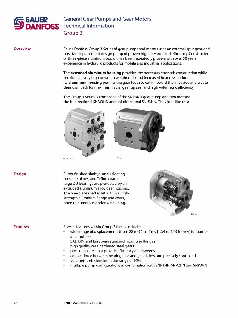
46 520L0557 • Rev DB • Jul 2009
General Gear Pumps and Gear MotorsTechnical Information
Sauer-Danfoss’ Group 3 Series of gear pumps and motors uses an external spur gear, and positivedisplacementdesignpumpofprovenhighpressureandefficiency.Constructedof three-piece aluminum body, it has been repeatedly proven, with over 30 years experience in hydraulic products for mobile and industrial applications.
The extruded aluminum housing provides the necessary strength construction while providing a very high power to weight ratio and increased heat dissipation. Its aluminum housing permits the gear teeth to cut in toward the inlet side and create their own path for maximum radial gear tip seal and high volumetric efficiency.
Overview
The Group 3 Series is composed of the SNP3NN gear pump and two motors: the bi-directional SNM3NN and uni-directional SNU3NN. They look like this:
Design Super finished shaft journals, floating pressure plates, and Teflon coated large DU bearings are protected by an extruded aluminum alloy gear housing. The one-piece shaft is set within a high-strength aluminum flange and cover, open to numerous options, including.
Features
Group 3
Special features within Group 3 family include:• widerangeofdisplacements(from22to90cm3/rev [1.34 to 5.49 in3/rev] for pumps
and motors)• SAE,DIN,andEuropeanstandardmountingflanges• highqualitycasehardenedsteelgears• pressureplatesthatprovideefficiencyatallspeeds• contactforcebetweenbearingfaceandgearislowandpreciselycontrolled• volumetricefficienciesintherangeof95%• multiplepumpconfigurationsincombinationwithSNP1NN,SNP2NNandSNP3NN.
F005 033 F005 045
F005 034
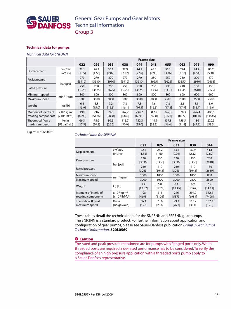
47520L0557 • Rev DB • Jul 2009
General Gear Pumps and Gear MotorsTechnical Information
Technical data for pumps
These tables detail the technical data for the SNP3NN and SEP3NN gear pumps. The SNP3NN is a standard product. For further information about application and configuration of gear pumps, please see Sauer-Danfoss publication Group 3 Gear Pumps Technical Information, 520L0569.
C CautionTheratedandpeakpressurementionedareforpumpswithflangedportsonly.Whenthreaded ports are required a de-rated performance has to be considered. To verify the compliance of an high pressure application with a threaded ports pump apply to a Sauer-Danfoss representative.
Group 3
1 kg•m2 = 23.68 lb•ft2
Technical data for SEP3NN Frame size
022 026 033 038 044
Displacementcm3/rev[in3/rev]
22.1[1.35]
26.2[1.60]
33.1[2.02]
37.9[2.32]
44.1[2.69]
Peak pressurebar [psi]
230 [3336]
230 [3336]
230 [3336]
230 [3336]
200[2910]
Rated pressure210
[3045]210
[3045]210
[3045]210
[3045]180
[2610]Minimum speed
min-1 (rpm)1000 1000 1000 1000 800
Maximum speed 3000 3000 3000 2800 2600
Weight kg [lb]5.7
[12.57]5.8
[12.79]6.1
[13.45]6.2
[13.67]6.4
[14.11]Moment of inertia ofrotating components
x 10-6 kg•m2
[x 10-6 lbf•ft2]198
[4698]216
[5126]246
[5873]294.2[6981]
312.2[7408]
Theoretical flow atmaximum speed
l/min[US gal/min]
66.3[17.5
78.6[20.8]
99.3[26.2]
113.7[30.0]
132.3[35.0]
Technical data for SNP3NN Frame size
022 026 033 038 044 048 055 063 075 090
Displacementcm3/rev[in3/rev]
22.1[1.35]
26.2[1.60]
33.1[2.02]
37.9[2.32]
44.1[2.69]
48.3[2.93]
55.1[3.36]
63.4[3.87]
74.4 [4.54]
88.2 [5.38]
Peak pressurebar [psi]
270[3910]
270[3910]
270[3910]
270[3910]
270[3910]
250 [3625]
250 [3625]
230 [3350]
200 [2910]
170 [2465]
Rated pressure250
[3625]250
[3625]250
[3625]250
[3625]250
[3625]230
[3336]230
[3336]210
[3045]180
[2610]150
[2175]Minimum speed
min-1(rpm)800 800 800 800 800 800 800 600 600 600
Maximum speed 3000 3000 3000 3000 3000 3000 2500 2500 2500 2500
Weight kg [lb]6.8
[15.0]6.8
[15.0]7.2
[15.8]7.3
[16.1]7.5
[16.5]7.6
[16.8]7.8
[17.3]8.1
[17.9]8.5
[18.7]8.9
[19.6]Moment of inertia ofrotating components
x 10-6kg•m2
[x 10-6lbf•ft2]198
[4698]216
[5126]246
[5838]267,2[6340]
294,2[6891]
312,2[7408]
342,3[8123]
378,3[8977]
426,4[10118]
486,5[11545]
Theoretical flow atmaximum speed
l/min[US gal/min]
66.3 [17.5]
78.6 [20.8]
99.3 [26.2]
113.7[30.0]
132.3[35.0]
144.9[38.3]
137.8[36.4]
158.5[41.8]
186[49.1]
220.5[58.3]
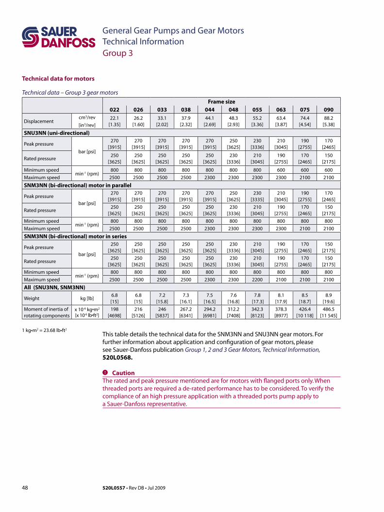
48 520L0557 • Rev DB • Jul 2009
General Gear Pumps and Gear MotorsTechnical Information
Technical data for motors
This table details the technical data for the SNM3NN and SNU3NN gear motors. For further information about application and configuration of gear motors, please see Sauer-Danfoss publication Group 1, 2 and 3 Gear Motors, Technical Information, 520L0568.
C CautionTheratedandpeakpressurementionedareformotorswithflangedportsonly.Whenthreaded ports are required a de-rated performance has to be considered. To verify the compliance of an high pressure application with a threaded ports pump apply to a Sauer-Danfoss representative.
Technical data – Group 3 gear motorsFrame size
022 026 033 038 044 048 055 063 075 090
Displacementcm3/rev
[in3/rev]
22.1[1.35]
26.2[1.60]
33.1[2.02]
37.9[2.32]
44.1[2.69]
48.3[2.93]
55.2[3.36]
63.4[3.87]
74.4[4.54]
88.2[5.38]
SNU3NN (uni-directional)
Peak pressure
bar [psi]
270[3915]
270[3915]
270[3915]
270[3915]
270[3915]
250[3625]
230[3336]
210[3045]
190[2755]
170[2465]
Rated pressure250
[3625]250
[3625]250
[3625]250
[3625]250
[3625]230
[3336]210
[3045]190
[2755]170
[2465]150
[2175]
Minimum speedmin-1(rpm)
800 800 800 800 800 800 800 600 600 600Maximum speed 2500 2500 2500 2500 2300 2300 2300 2300 2100 2100
SNM3NN (bi-directional) motor in parallel
Peak pressure
bar [psi]
270[3915]
270[3915]
270[3915]
270[3915]
270[3915]
250[3625]
230[3335]
210[3045]
190[2755]
170[2465]
Rated pressure250
[3625]250
[3625]250
[3625]250
[3625]250
[3625]230
[3336]210
[3045]190
[2755]170
[2465]150
[2175]Minimum speed
min-1(rpm)800 800 800 800 800 800 800 800 800 800
Maximum speed 2500 2500 2500 2500 2300 2300 2300 2300 2100 2100
SNM3NN (bi-directional) motor in series
Peak pressure
bar [psi]
250 [3625]
250 [3625]
250[3625]
250[3625]
250[3625]
230[3336]
210[3045]
190[2755]
170[2465]
150[2175]
Rated pressure250
[3625]250
[3625]250
[3625]250
[3625]250
[3625]230
[3336]210
[3045]190
[2755]170
[2465]150
[2175]Minimum speed
min-1(rpm)800 800 800 800 800 800 800 800 800 800
Maximum speed 2500 2500 2500 2500 2300 2300 2200 2100 2100 2100
All (SNU3NN, SNM3NN)
Weight kg [lb]6.8 [15]
6.8 [15]
7.2 [15.8]
7.3 [16.1]
7.5[16.5]
7.6[16.8]
7.8 [17.3]
8.1 [17.9]
8.5[18.7]
8.9[19.6]
Moment of inertia ofrotating components
x 10-6kg•m2
[x 10-6lb•ft2]198
[4698]216
[5126]246
[5837]267.2[6341]
294.2[6981]
312.2[7408]
342.3[8123]
378.3[8977]
426.4[10 118]
486.5[11 545]
1 kg•m2 = 23.68 lb•ft2
Group 3
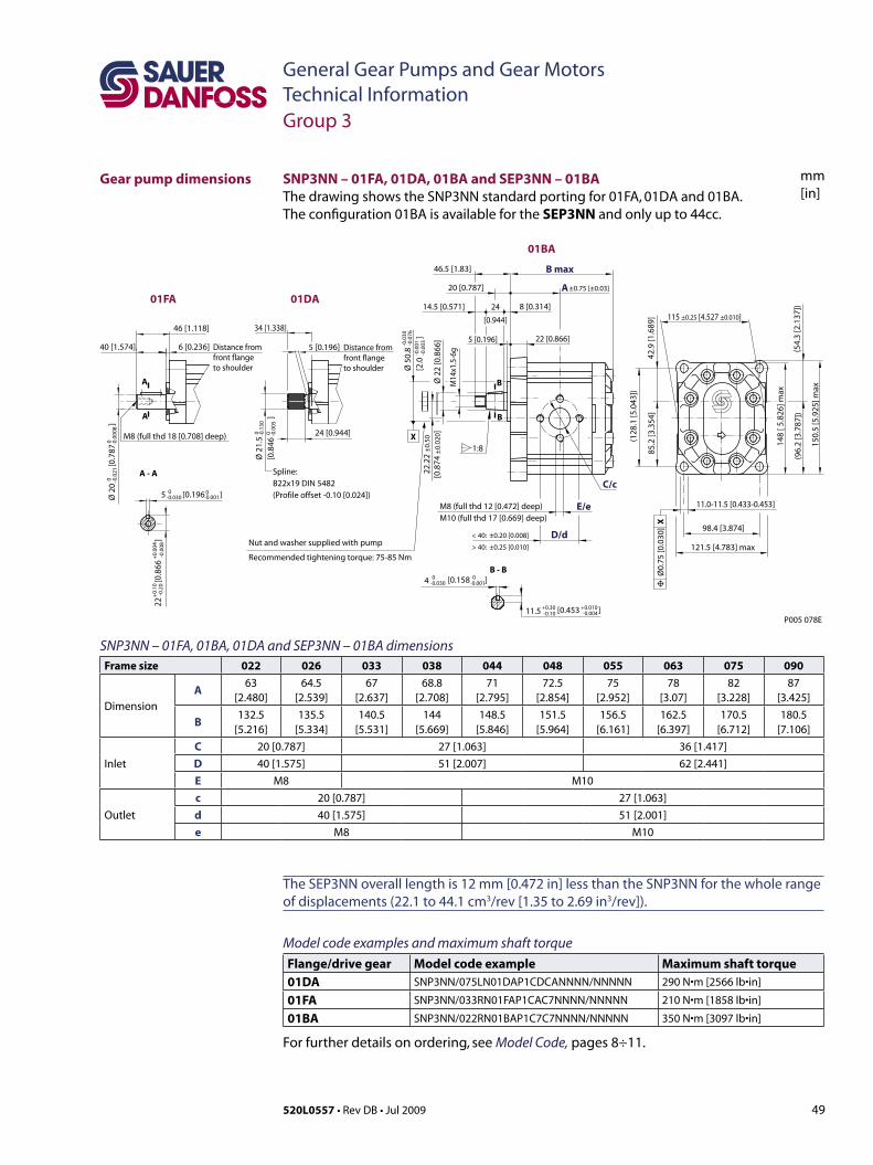
49520L0557 • Rev DB • Jul 2009
General Gear Pumps and Gear MotorsTechnical Information
mm[in]
Group 3
Gear pump dimensions
SNP3NN – 01FA, 01BA, 01DA and SEP3NN – 01BA dimensionsFrame size 022 026 033 038 044 048 055 063 075 090
Dimension
A63
[2.480]64.5
[2.539]67
[2.637]68.8
[2.708]71
[2.795]72.5
[2.854]75
[2.952]78
[3.07]82
[3.228]87
[3.425]
B132.5
[5.216]135.5
[5.334]140.5
[5.531]144
[5.669]148.5
[5.846]151.5
[5.964]156.5
[6.161]162.5
[6.397]170.5
[6.712]180.5
[7.106]
Inlet
C 20 [0.787] 27 [1.063] 36 [1.417]
D 40 [1.575] 51 [2.007] 62 [2.441]
E M8 M10
Outlet
c 20 [0.787] 27 [1.063]
d 40 [1.575] 51 [2.001]
e M8 M10
SNP3NN – 01FA, 01DA, 01BA and SEP3NN – 01BA The drawing shows the SNP3NN standard porting for 01FA, 01DA and 01BA. The configuration 01BA is available for the SEP3NN and only up to 44cc.
The SEP3NN overall length is 12 mm [0.472 in] less than the SNP3NN for the whole range of displacements (22.1 to 44.1 cm3/rev [1.35 to 2.69 in3/rev]).
Model code examples and maximum shaft torque Flange/drive gear Model code example Maximum shaft torque01DA SNP3NN/075LN01DAP1CDCANNNN/NNNNN 290 N•m[2566 lb•in]
01FA SNP3NN/033RN01FAP1CAC7NNNN/NNNNN 210 N•m[1858 lb•in]
01BA SNP3NN/022RN01BAP1C7C7NNNN/NNNNN 350 N•m[3097 lb•in]
For further details on ordering, see Model Code, pages 8÷11.
46.5 [1.83]
34 [1.338]46 [1.118]
6 [0.236]40 [1.574]
24 [0.944]
5 [0.196]
20 [0.787]
24
[0.944]
14.5 [0.571] 8 [0.314]
22 [0.866]5 [0.196]
±0.75 [±0.03]
121.5 [4.783] max
P005 078E
98.4 [3.874]
115 ±0.25 [4.527 ±0.010]
Ø 5
0.8
[2.0
]
-0.0
30-0
.076
-0.0
01-0
.003
Ø 2
0
[
0.78
7
]0 -0
.021
0 -0.0
008
Ø 2
2 [0
.866
]
M8 (full thd 12 [0.472] deep)M10 (full thd 17 [0.669] deep)
E/e
C/c
B max
D/d
A
01BA
01DA01FA
< 40: ±0.20 [0.008]
> 40: ±0.25 [0.010]
85.2
[3.3
54]
42.9
[1.6
89]
(128
.1 [5
.043
])
(54.
3 [2
.137
])
148
[ 5.8
26] m
ax
(96.
2 [3
.787
])
150.
5 [5
.925
] maxM
14x1
.5-6
g
22.2
2 ±
0.50
[0.8
74 ±
0.02
0]
1:8
B - B
A - A
B
B
A
A
11.0-11.5 [0.433-0.453]
Spline:B22x19 DIN 5482(Profile offset -0.10 [0.024])
Ø0.
75 [0
.030
] X
Distance from front flange to shoulder
Distance from front flange to shoulder
5 [0.196 ]0-0.030
0-0.001
-0.0
0822
[0.
866
]
+0.
10-0
.20
+0.
004
Ø 2
1.5
[0.8
46
]
0 -0.1
300 -0
.005
M8 (full thd 18 [0.708] deep)
[0.453 ]+0.30 +0.010-0.10 -0.004
4 0 0-0.030 [0.158 ]-0.001
11.5
X
Nut and washer supplied with pump
Recommended tightening torque: 75-85 Nm
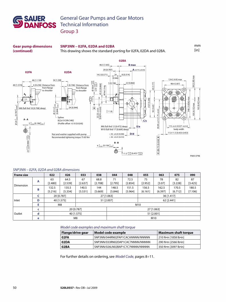
50 520L0557 • Rev DB • Jul 2009
General Gear Pumps and Gear MotorsTechnical Information
mm[in]
SNP3NN – 02FA, 02DA and 02BAThis drawing shows the standard porting for 02FA, 02DA and 02BA.
46.5 [1.83]
34 [1.338]46 [1.118]
6 [0.236]40 [1.574]
24 [0.944]
5 [0.196]
20 [0.787]
24
[0.944]
14.5 [0.571] 8 [0.314]
22 [0.866]5 [0.196]
±0.75 [±0.03]
P005 079E
115 ±0.25 [4.527 ±0.010]
Ø 5
0.8
[2.0
]
-0.0
30-0
.076
-0.0
01-0
.003
Ø 2
0
[
0.78
7
]0 -0
.021
0 -0.0
008
Ø 2
2 [0
.866
]
M8 (full thd 12 [0.472] deep)M10 (full thd 17 [0.669] deep)
E/e
C/c
B max
D/d
A
< 40: ±0.20 [0.008]
> 40: ±0.25 [0.010]
148
[ 5.8
26] m
ax
M14
x1.5
-6g
22.2
2 ±
0.50
[0.8
74 ±
0.02
0 ]
1:8
B - B
A - A
B
B
A
A
11.0-11.5 [0.433-0.453]
Spline:B22x19 DIN 5482(Profile offset -0.10 [0.024])
Ø0.
75 [0
.030
] X
Distance from front flange to shoulder
Distance from front flange to shoulder
5 [0.196 ]0-0.030
0-0.001
-0.0
0822
[0.
866
]
+0.
10-0
.20
+0.
004
Ø 2
1.5
[0.8
46
]
0 -0.1
300 -0
.005
M8 (full thd 18 [0.708] deep)
[0.453 ]+0.30 +0.010-0.10 -0.004
4 0 0-0.030 [0.158 ]-0.001
11.5
X
body width
124.5 [4.9] max
98.4 [3.87]
58 [2
.28]
max
105
[4.1
3] m
ax
163
[6.4
2] m
ax
(137
[5.3
9])
92 [3
.62]
44.4
4 ±
0.75
[1.7
5 ±
0.03
]
45 [1
.77]
02BA
02DA02FA
Nut and washer supplied with pumpRecommended tightening torque: 75-85 Nm
SNP3NN – 02FA, 02DA and 02BA dimensionsFrame size 022 026 033 038 044 048 055 063 075 090
Dimension
A63
[2.480]64.5
[2.539]67
[2.637]68.8
[2.708]71
[2.795]72.5
[2.854]75
[2.952]78
[3.07]82
[3.228]87
[3.425]
B132.5
[5.216]135.5
[5.334]140.5
[5.531]144
[5.669]148.5
[5.846]151.5
[5.964]156.5
[6.161]162.5
[6.397]170.5
[6.712]180.5
[7.106]
Inlet
C 20 [0.787] 27 [1.063] 36 [1.417]D 40 [1.575] 51 [2.007] 62 [2.441]E M8 M10
Outlet
c 20 [0.787] 27 [1.063]d 40 [1.575] 51 [2.001]e M8 M10
Group 3
Gear pump dimensions (continued)
Model code examples and maximum shaft torque Flange/drive gear Model code example Maximum shaft torque02FA SNP3NN/044RN02FAP1CACANNNN/NNNNN 210 N•m[1858 lb•in]
02DA SNP3NN/033RN02DAP1CAC7NNNN/NNNNN 290 N•m[2566 lb•in]
02BA SNP3NN/026LN02BAP1C7C7NNNN/NNNNN 350 N•m[3097 lb•in]
For further details on ordering, see Model Code, pages 8÷11.

51520L0557 • Rev DB • Jul 2009
General Gear Pumps and Gear MotorsTechnical Information
mm[in]
SNP3NN – 03FB and 03BBThis drawing shows the standard porting for 03FB and 03BB.
X
P005 080E
body width
Distance from front flange to cone reference diameter
-0.0
30-0
.076
-0.0
12-0
.003
A
D/d ±0.25 [±0.010]
B max
22.2
2 ±0
.50
[0.8
75 ±
0.02
0]
44.4
4 ±0
.75
[1.7
5 ±0
.030
]
Ø60
.3
[2.3
74
]
115 ±0.25[4.527 ±0.010]E/e
C/c
Ø 2
5 [0
.984
]
M16
x1.5
-6g
22 [0.866]
60 [2.362]
146.5 [5.768] max
114.3 [4.5]
9 [0.354]50 [1.968]
59 [2.323]
28.5 [1.122]
28[1.102]
14.5 [0.571]17.5 [0.689]
1:8
M10 (full thd 17 [0.669] deep)
±0.75 [±0.030]
8 [0.315]
B-B
B
B 148
[ 5.8
26] m
ax
(149
.5[
5.88
5])
100
[ 3.9
37]
49.5
[ 1
.949
]
116
[4.5
66] m
ax65
.5 [2
.578
] max
181.
5 [ 7
.145
] max
4.79 [0.189 ]0-0.30
0-0.012
-0.01013.5 [0.532 ]+0.15-0.25
+0.006
Ø 2
2
[
0.86
6
]0 -0
.021
0 -0.0
008
A - A
A
A
Distance from front flange to shoulder
5 [0.196 ]0-0.030
0-0.001
-0.0
0824
[0.
945
]
+0.
10-0
.20
+0.
004
M8 (full thd 18 [0.708] deep)
11.0-11.5 [0.433-0.453]Ø0.75 [0.030] X
03BB
03FB
Nut and washer supplied with pumpRecommended tightening torque: 95-105 Nm
Group 3
Gear pump dimensions (continued)
SNP3NN – 03FB and 03BB dimensionsFrame size 022 026 033 038 044 048 055 063 075 090
Dimension
A63
[2.480]64.5
[2.539]67
[2.637]68.8
[2.708]71
[2.795]72.5
[2.854]75
[2.952]78
[3.07]82
[3.228]87
[3.425]
B132.5
[5.216]135.5
[5.334]140.5
[5.531]144
[5.669]148.5
[5.846]151.5
[5.964]156.5
[6.161]162.5
[6.397]170.5
[6.712]180.5
[7.106]
Inlet
C 20 [0.787] 27 [1.063] 36 [1.417]
D 40 [1.575] 51 [2.007] 62 [2.441]
E M8 M10
Outlet
c 20 [0.787] 27 [1.063]
d 40 [1.575] 51 [2.001]
e M8 M10
Model code examples and maximum shaft torque Flange/drive gear Model code example Maximum shaft torque03FB SNP3NN/044LN03FBP1CACANNNN/NNNNN 300 N•m[2655 lb•in]
03BB SNP3NN/090RN03BBP1CDCANNNN/NNNNN 500 N•m[4425 lb•in]
For further details on ordering, see Model Code, pages 8÷11.
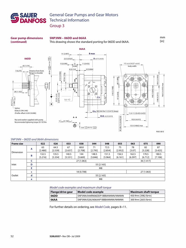
52 520L0557 • Rev DB • Jul 2009
General Gear Pumps and Gear MotorsTechnical Information
mm[in]
P005 081E
11.0-11.5 [0.433-0.453]
Ø0.
75 [0
.030
] X
40 [1.574]
1:5
45o
28 [1.102]
8 [0.314] 22 [0.866]
25 [0.984]
51 [2.007]
23.5 [0.925]
15 [0.590] 11 [0.433]
7 [0.275]
±0.75 [±0.03]
M8 (full thd 12 [0.472] deep)E/e
C/c
B max
D/d
A
A - A
A
A
Spline:B28x25 DIN 5482(Profile offset: 0.202 [0.008])
Distance from front flange to shoulder
5 [0.196 ]0-0.030
0-0.001
Ø 2
7.5
[1.0
82
]
0 -0.1
300 -0
.005
[0.512 ]+0.30 +0.010-0.10 -0.00413.0
123.5 [4.862] max
102.0 [4.015]
115 ±0.25 [4.527 ±0.010]
±0.25 [0.010]
22.2
2 ±
0.50
[0.8
74 ±
0.02
0]
X
body width
-0.0
36-0
.090
-0.0
01-0
.003
Ø10
5
[4.
133
]
Ø 2
5 [0
.984
]
M16
x1.5
-6g
(108
[4.2
51])
(58.
5[2
.303
])
148
[ 5.8
26] m
ax
166.
5 [ 6
.555
] max
(145
[5.7
08])
97 [3
.818
]48
[1.8
89]
06AA
06DD
Nut and washer supplied with pumpRecommended tightening torque: 95-105 Nm
SNP3NN – 06DD and 06AAThis drawing shows the standard porting for 06DD and 06AA.
Group 3
Gear pump dimensions (continued)
SNP3NN – 06DD and 06AA dimensionsFrame size 022 026 033 038 044 048 055 063 075 090
Dimension
A63
[2.480]64.5
[2.539]67
[2.637]68.8
[2.708]71
[2.795]72.5
[2.854]75
[2.952]78
[3.07]82
[3.228]87
[3.425]
B132.5
[5.216]135.5
[5.334]140.5
[5.531]144
[5.669]148.5
[5.846]151.5
[5.964]156.5
[6.161]162.5
[6.397]170.5
[6.712]180.5
[7.106]
Inlet
C 27 [1.063] 36 [1.417]
D 55 [2.165]
E M8
Outlet
c 18 [0.708] 27 [1.063]
d 55 [2.165]
e M8
Model code examples and maximum shaft torque Flange/drive gear Model code example Maximum shaft torque06DD SNP3NN/044RN06DDP1BBBANNNN/NNNNN 450 N•m[3982 lb•in]
06AA SNP3NN/026LN06AAP1BBBANNNN/NNNNN 300 N•m[2655 lb•in]
For further details on ordering, see Model Code, pages 8÷11.
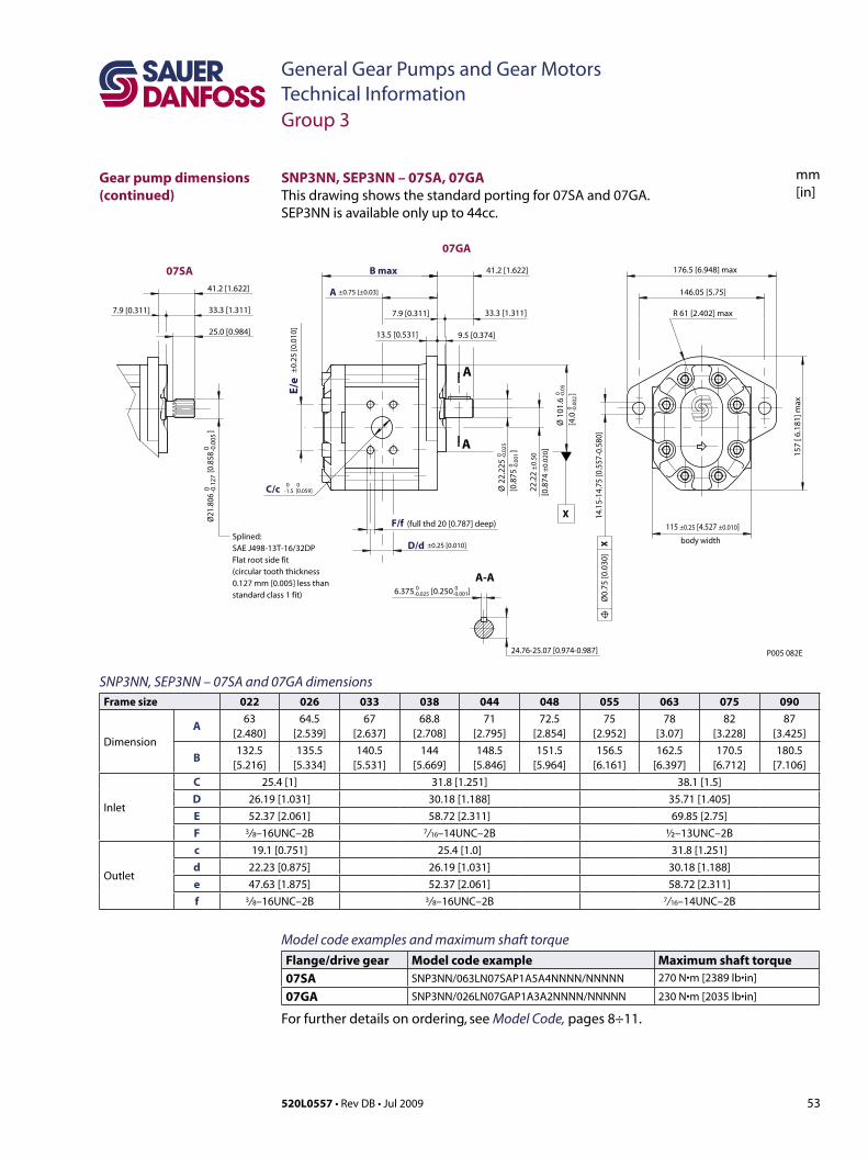
53520L0557 • Rev DB • Jul 2009
General Gear Pumps and Gear MotorsTechnical Information
mm[in]
SNP3NN, SEP3NN – 07SA and 07GA dimensionsFrame size 022 026 033 038 044 048 055 063 075 090
Dimension
A63
[2.480]64.5
[2.539]67
[2.637]68.8
[2.708]71
[2.795]72.5
[2.854]75
[2.952]78
[3.07]82
[3.228]87
[3.425]
B132.5
[5.216]135.5
[5.334]140.5
[5.531]144
[5.669]148.5
[5.846]151.5
[5.964]156.5
[6.161]162.5
[6.397]170.5
[6.712]180.5
[7.106]
Inlet
C 25.4 [1] 31.8 [1.251] 38.1 [1.5]D 26.19 [1.031] 30.18 [1.188] 35.71 [1.405]E 52.37 [2.061] 58.72 [2.311] 69.85 [2.75]F 3/ 8–16UNC–2B 7/ 16–14UNC–2B ½–13UNC–2B
Outlet
c 19.1 [0.751] 25.4 [1.0] 31.8 [1.251]d 22.23 [0.875] 26.19 [1.031] 30.18 [1.188]e 47.63 [1.875] 52.37 [2.061] 58.72 [2.311]f 3/ 8–16UNC–2B 3/ 8–16UNC–2B 7/ 16–14UNC–2B
SNP3NN, SEP3NN – 07SA, 07GAThis drawing shows the standard porting for 07SA and 07GA. SEP3NN is available only up to 44cc.
±0.75 [±0.03]
(full thd 20 [0.787] deep)
F/f
B max
D/d
A
6.375 [0.250 ]0-0.025
0 0 -1.5 [0.059]
0-0.001
115 ±0.25 [4.527 ±0.010]
±0.25 [0.010]
C/c
E/e
±0.
25 [0
.010
]
22.2
2 ±
0.50
[0
.874
±0.
020]
body width
0 -0.1
270 -0
.005
Ø21
.806
[0.8
58
]
176.5 [6.948] max
R 61 [2.402] max
146.05 [5.75]
41.2 [1.622]
41.2 [1.622]
33.3 [1.311] 33.3 [1.311]
25.0 [0.984]
7.9 [0.311] 7.9 [0.311]
13.5 [0.531] 9.5 [0.374]
157
[ 6.1
81] m
ax
14.1
5-14
.75
[0.5
57-0
.580
]
24.76-25.07 [0.974-0.987]
Ø0.
75 [0
.030
] X
Ø 2
2.22
5 [0
.875
]
0 -0.0
25
0 -0.0
01
Ø 1
01.6
[4
.0
] 0 -0.0
5 0 -0
.002
X
A
A
A-A
Splined:SAE J498-13T-16/32DPFlat root side fit(circulartooththickness0.127 mm [0.005] less thanstandard class 1 fit)
P005 082E
07GA
07SA
Group 3
Gear pump dimensions (continued)
Model code examples and maximum shaft torque Flange/drive gear Model code example Maximum shaft torque07SA SNP3NN/063LN07SAP1A5A4NNNN/NNNNN 270 N•m[2389 lb•in]
07GA SNP3NN/026LN07GAP1A3A2NNNN/NNNNN 230 N•m[2035 lb•in]
For further details on ordering, see Model Code, pages 8÷11.
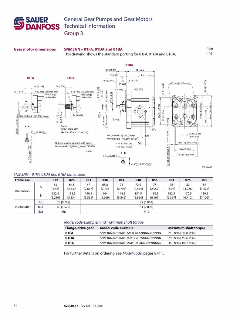
54 520L0557 • Rev DB • Jul 2009
General Gear Pumps and Gear MotorsTechnical Information
mm[in]
SNM3NN – 01FA, 01DA and 01BA dimensionsFrame size 022 026 033 038 044 048 055 063 075 090
Dimension
A63
[2.48]64.5
[2.539]67
[2.637]68.8
[2.70871
[2.795]72.5
[2.854]75
[2.952]78
[3.07]82
[3.228]87
[3.425]
B132.5
[5.216]135.5
[5.334]140.5
[5.531]144
[5.669]148.5
[5.846]151.5
[5.964]156.5
[6.161]162.5
[6.397]170.5
[6.712]180.5
[7.106]
Inlet/Outlet
C/c 20 [0.787] 27 [1.063]D/d 40 [1.575] 51 [2.007]E/e M8 M10
SNM3NN – 01FA, 01DA and 01BA This drawing shows the standard porting for 01FA, 01DA and 01BA.
46.5 [1.83]
34 [1.338]46 [1.118]
6 [0.236]40 [1.574]
24 [0.944]
5 [0.196]
20 [0.787]
24
[0.944]
14.5 [0.571] 8 [0.314]
22 [0.866]5 [0.196]
±0.75 [±0.03]
121.5 [4.783] max
P005 083E
98.4 [3.874]
115 ±0.25 [4.527 ±0.010]
Ø 5
0.8
[2.0
]
-0.0
30-0
.076
-0.0
01-0
.003
Ø 2
0
[
0.78
7
]0 -0
.021
0 -0.0
008
Ø 2
2 [0
.866
]
M8 (full thd 12 [0.472] deep)M10 (full thd 17 [0.669] deep)
E/e
C/c
B max
D/d
A
< 40: ±0.20 [0.008]
> 40: ±0.25 [0.010]
85.2
[3.3
54]
42.9
[1.6
89]
(128
.1 [5
.043
])
(54.
3 [2
.137
])
148
[ 5.8
26] m
ax
(96.
2 [3
.787
])
150.
5 [5
.925
] maxM
14x1
.5-6
g
22.2
2 ±
0.50
[0.8
74 ±
0.02
0]
44.4
4 ±
0.75
[1.
749
±0.
03]
1:8
B - B
A - A
B
B
A
A
11.0-11.5 [0.433-0.453]
Spline:B22x19 DIN 5482(Profile offset -0.10 [0.024])
Ø0.
75 [0
.030
] X
Distance from front flange to shoulder
Distance from front flange to shoulder
5 [0.196 ]0-0.030
0-0.001
-0.0
0822
[0.
866
]
+0.
10-0
.20
+0.
004
Ø 2
1.5
[0.8
46
]
0 -0.1
300 -0
.005
M8 (full thd 18 [0.708] deep)
[0.453 ]+0.30 +0.010-0.10 -0.004
4 0 0-0.030 [0.158 ]-0.001
11.5
X
M14x1.5-6HDrain port
01BA
01DA01FA
Nut and washer supplied with pumpRecommended tightening torque: 75-85 Nm
Group 3
Gear motor dimensions
Model code examples and maximum shaft torque Flange/drive gear Model code example Maximum shaft torque01FA SNM3NN/075BN01FAM1CACANNNN/NNNNN 210 N•m[1858 lb•in]
01DA SNM3NN/026BN01DAM1C7C7NNNN/NNNNN 290 N•m[2566 lb•in]
01BA SNM3NN/044BN01BAM1CACANNNN/NNNNN 350 N•m[3097 lb•in]
For further details on ordering, see Model Code, pages 8÷11.
motor
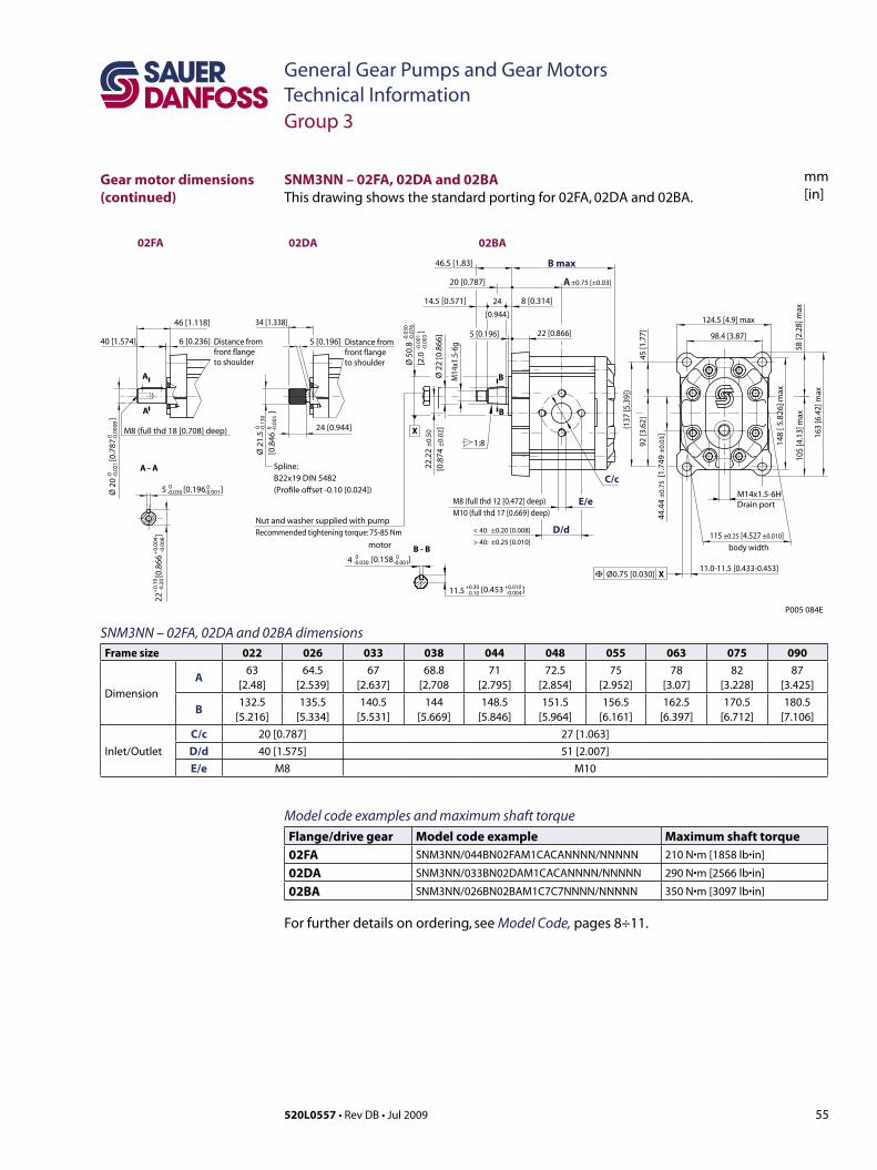
55520L0557 • Rev DB • Jul 2009
General Gear Pumps and Gear MotorsTechnical Information
mm[in]
SNM3NN – 02FA, 02DA and 02BA dimensionsFrame size 022 026 033 038 044 048 055 063 075 090
Dimension
A63
[2.48]64.5
[2.539]67
[2.637]68.8
[2.70871
[2.795]72.5
[2.854]75
[2.952]78
[3.07]82
[3.228]87
[3.425]
B132.5
[5.216]135.5
[5.334]140.5
[5.531]144
[5.669]148.5
[5.846]151.5
[5.964]156.5
[6.161]162.5
[6.397]170.5
[6.712]180.5
[7.106]
Inlet/Outlet
C/c 20 [0.787] 27 [1.063]D/d 40 [1.575] 51 [2.007]E/e M8 M10
SNM3NN – 02FA, 02DA and 02BAThis drawing shows the standard porting for 02FA, 02DA and 02BA.
46.5 [1.83]
34 [1.338]46 [1.118]
6 [0.236]40 [1.574]
24 [0.944]
5 [0.196]
20 [0.787]
24
[0.944]
14.5 [0.571] 8 [0.314]
22 [0.866]5 [0.196]
±0.75 [±0.03]
P005 084E
115 ±0.25 [4.527 ±0.010]
Ø 5
0.8
[2.0
]
-0.0
30-0
.076
-0.0
01-0
.003
Ø 2
0
[
0.78
7
]0 -0
.021
0 -0.0
008
Ø 2
2 [0
.866
]
M8 (full thd 12 [0.472] deep)M10 (full thd 17 [0.669] deep)
E/e
C/c
B max
D/d
A
< 40: ±0.20 [0.008]
> 40: ±0.25 [0.010]
148
[ 5.8
26] m
ax
M14
x1.5
-6g
22.2
2 ±
0.50
[0.8
74 ±
0.02
]1:8
B - B
A - A
B
B
A
A
11.0-11.5 [0.433-0.453]
Spline:B22x19 DIN 5482(Profile offset -0.10 [0.024])
Ø0.75 [0.030] X
Distance from front flange to shoulder
Distance from front flange to shoulder
5 [0.196 ]0-0.030
0-0.001
-0.0
0822
[0.
866
]
+0.
10-0
.20
+0.
004
Ø 2
1.5
[0.8
46
]
0 -0.1
300 -0
.005
M8 (full thd 18 [0.708] deep)
[0.453 ]+0.30 +0.010-0.10 -0.004
4 0 0-0.030 [0.158 ]-0.001
11.5
X
body width
124.5 [4.9] max
98.4 [3.87]
58 [2
.28]
max
105
[4.1
3] m
ax
163
[6.4
2] m
ax
(137
[5.3
9])
92 [3
.62]
45 [1
.77]
44.4
4 ±
0.75
[1.
749
±0.
03]
M14x1.5-6HDrain port
02BA02DA02FA
Nut and washer supplied with pumpRecommended tightening torque: 75-85 Nm
Group 3
Gear motor dimensions (continued)
Model code examples and maximum shaft torque Flange/drive gear Model code example Maximum shaft torque02FA SNM3NN/044BN02FAM1CACANNNN/NNNNN 210 N•m[1858 lb•in]
02DA SNM3NN/033BN02DAM1CACANNNN/NNNNN 290 N•m[2566 lb•in]
02BA SNM3NN/026BN02BAM1C7C7NNNN/NNNNN 350 N•m[3097 lb•in]
For further details on ordering, see Model Code, pages 8÷11.
motor
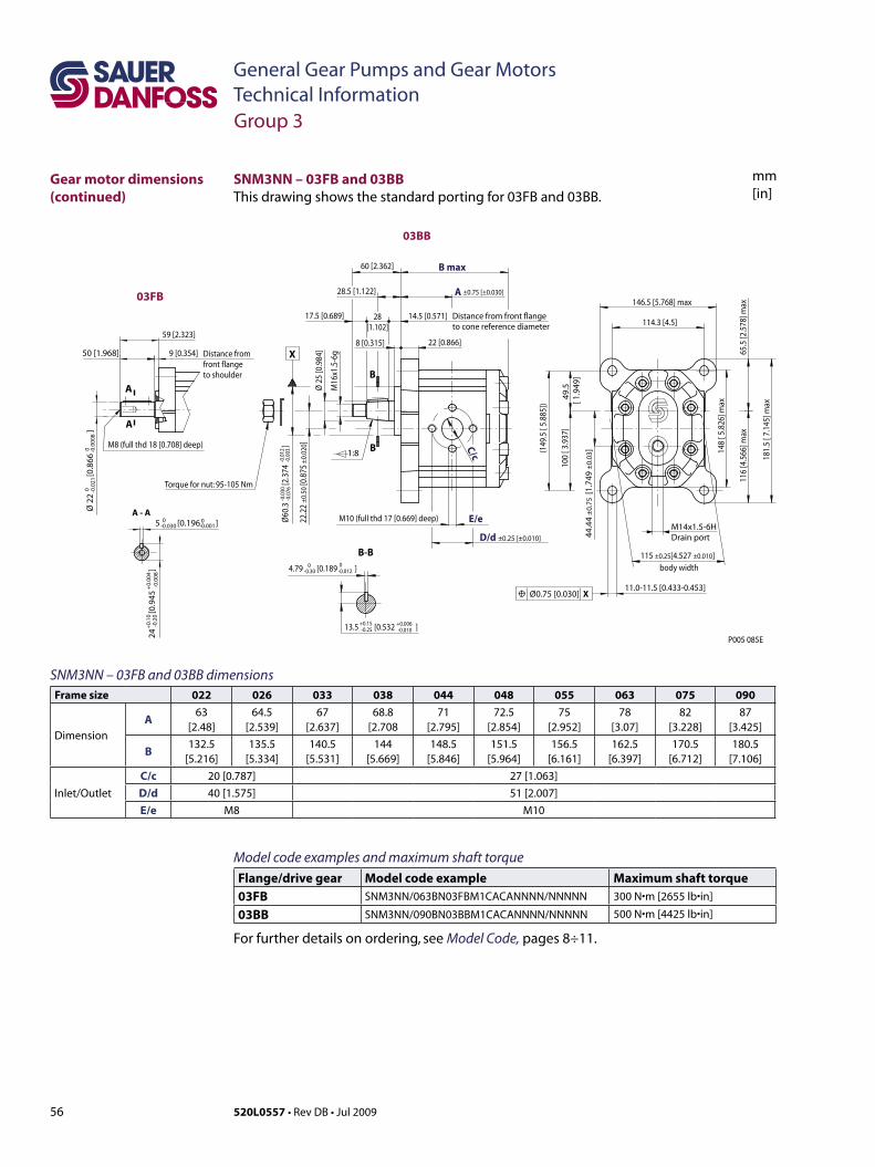
56 520L0557 • Rev DB • Jul 2009
General Gear Pumps and Gear MotorsTechnical Information
mm[in]
SNM3NN – 03FB and 03BBThis drawing shows the standard porting for 03FB and 03BB.
Group 3
Gear motor dimensions (continued)
SNM3NN – 03FB and 03BB dimensionsFrame size 022 026 033 038 044 048 055 063 075 090
Dimension
A63
[2.48]64.5
[2.539]67
[2.637]68.8
[2.70871
[2.795]72.5
[2.854]75
[2.952]78
[3.07]82
[3.228]87
[3.425]
B132.5
[5.216]135.5
[5.334]140.5
[5.531]144
[5.669]148.5
[5.846]151.5
[5.964]156.5
[6.161]162.5
[6.397]170.5
[6.712]180.5
[7.106]
Inlet/Outlet
C/c 20 [0.787] 27 [1.063]D/d 40 [1.575] 51 [2.007]E/e M8 M10
Model code examples and maximum shaft torque Flange/drive gear Model code example Maximum shaft torque03FB SNM3NN/063BN03FBM1CACANNNN/NNNNN 300 N•m[2655 lb•in]
03BB SNM3NN/090BN03BBM1CACANNNN/NNNNN 500 N•m[4425 lb•in]
For further details on ordering, see Model Code, pages 8÷11.
X
P005 085E
body width
Distance from front flange to cone reference diameter
-0.0
30-0
.076
-0.0
12-0
.003
A
D/d ±0.25 [±0.010]
B max
22.2
2±0
.50
[0.8
75±0
.020
]
Ø60
.3
[2.3
74
]
115 ±0.25[4.527 ±0.010]
E/e
C/c
Ø25
[0.9
84]
M16
x1.5
-6g
22 [0.866]
60 [2.362]
146.5 [5.768] max
114.3 [4.5]
9 [0.354]50 [1.968]
59 [2.323]
28.5 [1.122]
28[1.102]
14.5 [0.571]17.5 [0.689]
1:8
M10 (full thd 17 [0.669] deep)
±0.75 [±0.030]
8 [0.315]
B-B
B
B 148
[ 5.8
26] m
ax
(149
.5 [
5.88
5])
100
[ 3.9
37]
49.5
[ 1.9
49]
116
[4.5
66] m
ax65
.5 [2
.578
] max
181.
5 [ 7
.145
] max
4.79 [0.189 ]0-0.30
0-0.012
-0.01013.5 [0.532 ] +0.15-0.25
+0.006
Ø 2
2
[
0.86
6
]0 -0
.021
0 -0.0
008
A - A
A
A
Distance from front flange to shoulder
5 [0.196 ]0-0.030
0-0.001
-0.0
0824
[0.
945
]
+0.
10-0
.20
+0.
004
M8 (full thd 18 [0.708] deep)
Torque for nut: 95-105 Nm
11.0-11.5 [0.433-0.453]Ø0.75 [0.030] X
44.4
4±
0.75
[1.7
49±
0.03
]
M14x1.5-6HDrain port
03BB
03FB
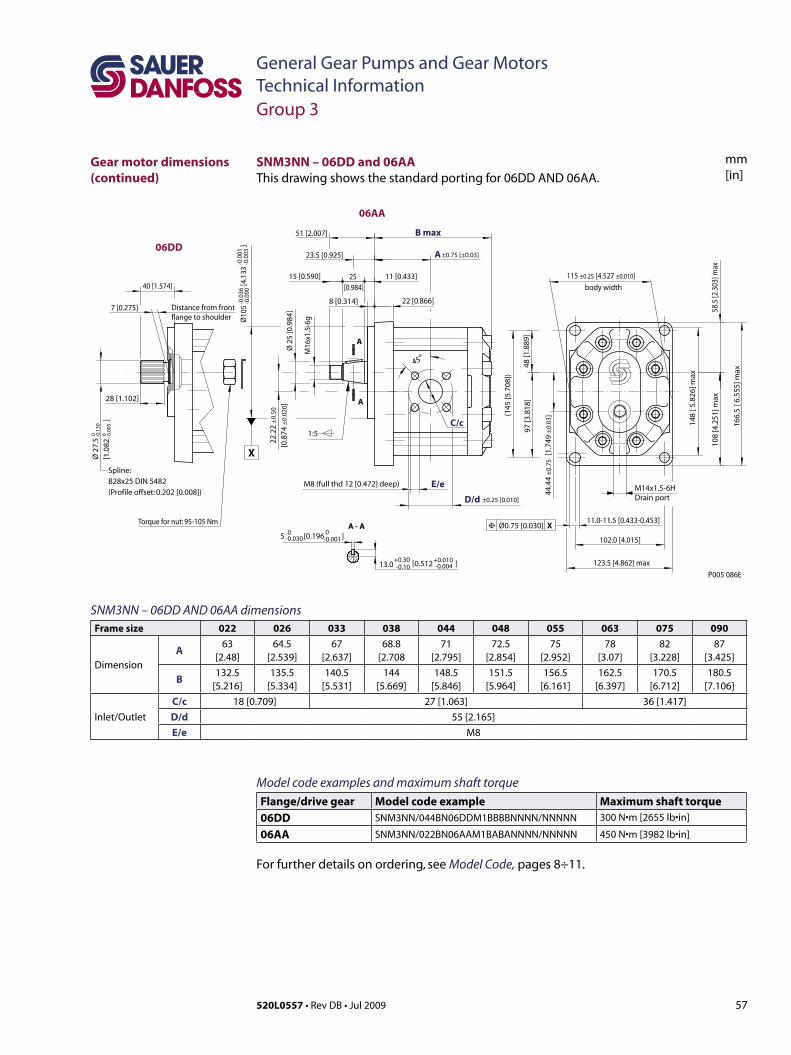
57520L0557 • Rev DB • Jul 2009
General Gear Pumps and Gear MotorsTechnical Information
mm[in]
SNM3NN – 06DD AND 06AA dimensionsFrame size 022 026 033 038 044 048 055 063 075 090
Dimension
A63
[2.48]64.5
[2.539]67
[2.637]68.8
[2.70871
[2.795]72.5
[2.854]75
[2.952]78
[3.07]82
[3.228]87
[3.425]
B132.5
[5.216]135.5
[5.334]140.5
[5.531]144
[5.669]148.5
[5.846]151.5
[5.964]156.5
[6.161]162.5
[6.397]170.5
[6.712]180.5
[7.106]
Inlet/Outlet
C/c 18 [0.709] 27 [1.063] 36 [1.417]D/d 55 [2.165]E/e M8
SNM3NN – 06DD and 06AAThis drawing shows the standard porting for 06DD AND 06AA.
Group 3
Model code examples and maximum shaft torque Flange/drive gear Model code example Maximum shaft torque06DD SNM3NN/044BN06DDM1BBBBNNNN/NNNNN 300 N•m[2655 lb•in]
06AA SNM3NN/022BN06AAM1BABANNNN/NNNNN 450 N•m[3982 lb•in]
For further details on ordering, see Model Code, pages 8÷11.
P005 086E
11.0-11.5 [0.433-0.453]Ø0.75 [0.030] X
40 [1.574]
1:5
45o
28 [1.102]
8 [0.314] 22 [0.866]
25 [0.984]
51 [2.007]
23.5 [0.925]
15 [0.590] 11 [0.433]
7 [0.275]
±0.75 [±0.03]
M8 (full thd 12 [0.472] deep) E/e
C/c
B max
D/d
A
A - A
A
A
Spline:B28x25 DIN 5482(Profile offset: 0.202 [0.008])
Distance from front flange to shoulder
5 [0.196 ]0-0.030
0-0.001
Ø 2
7.5
[1.0
82
]
0 -0.1
300 -0
.005
[0.512 ]+0.30 +0.010-0.10 -0.00413.0 123.5 [4.862] max
102.0 [4.015]
115 ±0.25 [4.527 ±0.010]
±0.25 [0.010]
22.2
2 ±
0.50
[0.8
74 ±
0.02
0]
X
body width
-0.0
36-0
.090
-0.0
01-0
.003
Ø10
5
[4.
133
]
Ø 2
5 [0
.984
]
M16
x1.5
-6g
108
[4.2
51] m
ax58
.5 [2
.303
] max
148
[ 5.8
26] m
ax
166.
5 [ 6
.555
] max
(145
[5.7
08])
97 [3
.818
]48
[1.8
89]
44.4
4 ±
0.75
[1.
749
±0.
03]
M14x1.5-6HDrain port
06DD
06AA
Torque for nut: 95-105 Nm
Gear motor dimensions (continued)
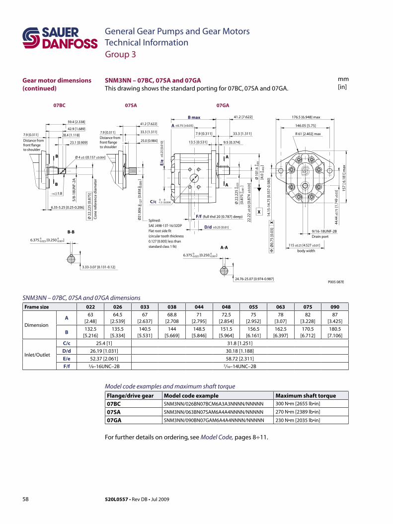
58 520L0557 • Rev DB • Jul 2009
General Gear Pumps and Gear MotorsTechnical Information
mm[in]
SNM3NN – 07BC, 07SA and 07GA dimensionsFrame size 022 026 033 038 044 048 055 063 075 090
Dimension
A63
[2.48]64.5
[2.539]67
[2.637]68.8
[2.70871
[2.795]72.5
[2.854]75
[2.952]78
[3.07]82
[3.228]87
[3.425]
B132.5
[5.216]135.5
[5.334]140.5
[5.531]144
[5.669]148.5
[5.846]151.5
[5.964]156.5
[6.161]162.5
[6.397]170.5
[6.712]180.5
[7.106]
Inlet/Outlet
C/c 25.4 [1] 31.8 [1.251]D/d 26.19 [1.031] 30.18 [1.188]E/e 52.37 [2.061] 58.72 [2.311]F/f 3/ 8–16UNC–2B 7/ 16–14UNC–2B
Group 3
SNM3NN – 07BC, 07SA and 07GA Thisdrawingshowsthestandardportingfor07BC,07SAand07GA.
Model code examples and maximum shaft torque Flange/drive gear Model code example Maximum shaft torque07BC SNM3NN/026BN07BCM6A3A3NNNN/NNNNN 300 N•m[2655 lb•in]
07SA SNM3NN/063BN07SAM6A4A4NNNN/NNNNN 270 N•m[2389 lb•in]
07GA SNM3NN/090BN07GAM6A4A4NNNN/NNNNN 230 N•m[2035 lb•in]
For further details on ordering, see Model Code, pages 8÷11.
±0.75 [±0.03]
(full thd 20 [0.787] deep)F/f
B max
D/d
A
6.375 [0.250 ]0-0.025
0 0-1.5 [0.059]
0-0.001
115 ±0.25 [4.527 ±0.01]
±0.25 [0.01]
C/c
E/e
±0.
25 [0
.010
]
22.2
2±
0.50
[0.8
74±
0.02
0]body width
0 -0.1
270 -0
.005
Ø21
.806
[0.8
58
]
176.5 [6.948] max
R 61 [2.402] max
146.05 [5.75]
41.2 [7.622]
41.2 [7.622]
33.3 [1.311]33.3 [1.311]
25.0 [0.984]
7.9 [0.311]7.9 [0.311]7.9 [0.311]
13.5 [0.531] 9.5 [0.374]
157
[ 6.1
81] m
ax
14.1
5-14
.75
[0.5
57-0
.580
]
6.35-5.25 [0.25-0.206]
24.76-25.07 [0.974-0.987]
Ø0.
75 [0
.03]
X
Ø 2
2.22
5[0
.875
]
0 -0.0
250 -0
.001
Ø 1
01.6
[4.0
]0 -0
.05
0 -0.0
02
X
A
A
B
B
A-A
6.375 [0.250 ]0-0.025
0-0.001
3.33-3.07 [0.131-0.12]
B-B
Splined:SAE J498-13T-16/32DPFlat root side fit(circular tooth thickness0.127 [0.005] less thanstandard class 1 fit)
P005 087E
9/16-18UNF-2BDrain port
5/8-
18U
NF-
2A
28.4 [1.118]
59.4 [2.338]
42.9 [1.689]
23.1 [0.909]
Ø 2
2.22
5 [0
.875
]
Co
ne
refe
ren
ce d
iam
eter
Distance from front flange to shoulder
Distance from front flange to shoulder
Ø 4 ±0.1[0.157 ±0.004]
44.4
4±0
.75
[1.7
49±0
.03]
07GA07SA07BC
1:8
Gear motor dimensions (continued)
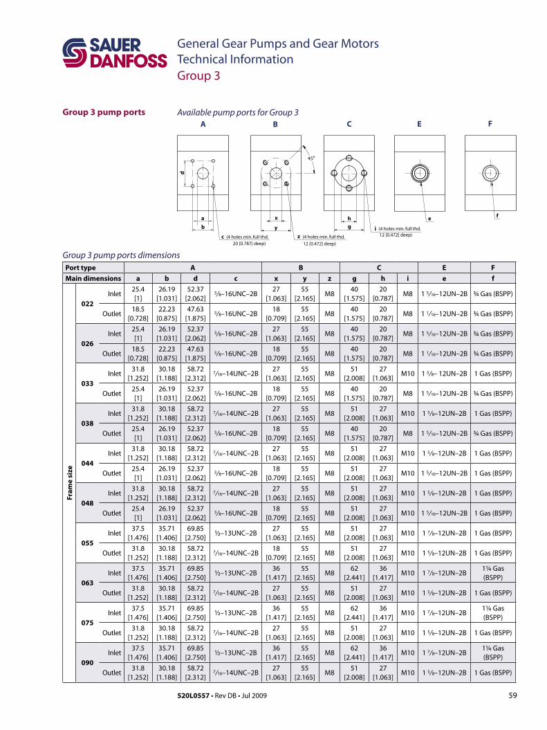
59520L0557 • Rev DB • Jul 2009
General Gear Pumps and Gear MotorsTechnical Information
Group 3 pump ports
Group 3
g
CB FE
i
h
(4holesmin. full thd.12 [0.472] deep)
x
y
z
45o
(4holesmin. full thd.
12 [0.472] deep)
fe
A
a
c (4holesmin. full thd. 20 [0.787] deep)
b
d
Group 3 pump ports dimensionsPort type A B C E FMain dimensions a b d c x y z g h i e f
Fram
e si
ze
022Inlet
25.4[1]
26.19[1.031]
52.37 [2.062]
3/ 8–16UNC–2B27
[1.063]55
[2.165]M8
40 [1.575]
20 [0.787]
M8 1 5/ 16–12UN–2B ¾ Gas (BSPP)
Outlet18.5
[0.728]22.23
[0.875]47.63
[1.875]3/ 8–16UNC–2B
18 [0.709]
55 [2.165]
M840
[1.575]20
[0.787]M8 1 1/ 16–12UN–2B ¾ Gas (BSPP)
026Inlet
25.4 [1]
26.19 [1.031]
52.37 [2.062]
3/ 8–16UNC–2B27
[1.063]55
[2.165]M8
40 [1.575]
20 [0.787]
M8 1 5/ 16–12UN–2B ¾ Gas (BSPP)
Outlet18.5
[0.728]22.23
[0.875]47.63
[1.875]3/ 8–16UNC–2B
18 [0.709]
55 [2.165]
M840
[1.575]20
[0.787]M8 1 1/ 16–12UN–2B ¾ Gas (BSPP)
033Inlet
31.8 [1.252]
30.18 [1.188]
58.72 [2.312]
7/ 16–14UNC–2B27
[1.063]55
[2.165]M8
51 [2.008]
27 [1.063]
M10 1 5/ 8– 12UN–2B 1 Gas (BSPP)
Outlet25.4 [1]
26.19 [1.031]
52.37 [2.062]
3/ 8–16UNC–2B18
[0.709]55
[2.165]M8
40 [1.575]
20 [0.787]
M8 1 5/ 16–12UN–2B ¾ Gas (BSPP)
038Inlet
31.8 [1.252]
30.18 [1.188]
58.72 [2.312]
7/ 16–14UNC–2B27
[1.063]55
[2.165]M8
51 [2.008]
27 [1.063]
M10 1 5/ 8–12UN–2B 1 Gas (BSPP)
Outlet25.4 [1]
26.19 [1.031]
52.37 [2.062]
3/ 8–16UNC–2B18
[0.709]55
[2.165]M8
40 [1.575]
20 [0.787]
M8 1 5/ 16–12UN–2B ¾ Gas (BSPP)
044Inlet
31.8 [1.252]
30.18 [1.188]
58.72 [2.312]
7/ 16–14UNC–2B27
[1.063]55
[2.165]M8
51 [2.008]
27 [1.063]
M10 1 5/ 8–12UN–2B 1 Gas (BSPP)
Outlet25.4 [1]
26.19 [1.031]
52.37 [2.062]
3/ 8–16UNC–2B18
[0.709]55
[2.165]M8
51 [2.008]
27 [1.063]
M10 1 5/ 16–12UN–2B 1 Gas (BSPP)
048Inlet
31.8 [1.252]
30.18 [1.188]
58.72 [2.312]
7/ 16–14UNC–2B27
[1.063]55
[2.165]M8
51 [2.008]
27 [1.063]
M10 1 5/ 8–12UN–2B 1 Gas (BSPP)
Outlet25.4 [1]
26.19 [1.031]
52.37 [2.062]
3/ 8–16UNC–2B18
[0.709]55
[2.165]M8
51 [2.008]
27 [1.063]
M10 1 5/ 16–12UN–2B 1 Gas (BSPP)
055Inlet
37.5[1.476]
35.71 [1.406]
69.85 [2.750]
½–13UNC–2B27
[1.063]55
[2.165]M8
51 [2.008]
27 [1.063]
M10 1 7/ 8–12UN–2B 1 Gas (BSPP)
Outlet31.8
[1.252]30.18
[1.188]58.72
[2.312]7/ 16–14UNC–2B
18 [0.709]
55 [2.165]
M851
[2.008]27
[1.063]M10 1 5/ 8–12UN–2B 1 Gas (BSPP)
063Inlet
37.5[1.476]
35.71 [1.406]
69.85 [2.750]
½–13UNC–2B36
[1.417]55
[2.165]M8
62 [2.441]
36 [1.417]
M10 1 7/ 8–12UN–2B1¼ Gas (BSPP)
Outlet31.8
[1.252]30.18
[1.188]58.72
[2.312]7/ 16–14UNC–2B
27 [1.063]
55 [2.165]
M851
[2.008]27
[1.063]M10 1 5/ 8–12UN–2B 1 Gas (BSPP)
075Inlet
37.5[1.476]
35.71 [1.406]
69.85 [2.750]
½–13UNC–2B36
[1.417]55
[2.165]M8
62 [2.441]
36 [1.417]
M10 1 7/ 8–12UN–2B1¼ Gas (BSPP)
Outlet31.8
[1.252]30.18
[1.188]58.72
[2.312]7/ 16–14UNC–2B
27 [1.063]
55 [2.165]
M851
[2.008]27
[1.063]M10 1 5/ 8–12UN–2B 1 Gas (BSPP)
090Inlet
37.5[1.476]
35.71 [1.406]
69.85 [2.750]
½–13UNC–2B36
[1.417]55
[2.165]M8
62 [2.441]
36 [1.417]
M10 1 7/ 8–12UN–2B1¼ Gas (BSPP)
Outlet31.8
[1.252]30.18
[1.188]58.72
[2.312]7/ 16–14UNC–2B
27 [1.063]
55 [2.165]
M851
[2.008]27
[1.063]M10 1 5/ 8–12UN–2B 1 Gas (BSPP)
Available pump ports for Group 3

60 520L0557 • Rev DB • Jul 2009
General Gear Pumps and Gear MotorsTechnical InformationGroup 3
Group 3 motor ports
g
CB FE
i
h
(4holesmin. full thd.12 [0.472] deep)
x
y
z
45o
(4holesmin. full thd.
12 [0.472] deep)
fe
A
a
c (4holesmin. full thd. 20 [0.787] deep)
b
d
Group 3 motor ports dimensionsPort type A B C E FMain dimensions a b d c x y z g h i e f
Fram
e si
ze
022Inlet/Outlet
25.4[1.0]
26.19[1.031]
52.37[2.061] ³⁄8–16UNC–2B
18 [0.709]
55 [2.165]
M840
[1.575]20
[0.787]M8 15⁄16–12UN–2B ¾ Gas (BSPP)
026Inlet/Outlet
25.4[1.0]
26.19[1.031]
52.37[2.061] ³⁄8–16UNC–2B
18 [0.709]
55 [2.165]
M840
[1.575]20
[0.787]M8 15⁄16–12UN–2B ¾ Gas (BSPP)
033Inlet/Outlet
31.8[1.251]
30.18[1.188]
58.72[2.311] 7⁄16–14UNC–2B
27 [1.063]
55 [2.165]
M851
[2.008]27
[1.063]M10 15⁄8– 12UN–2B 1 Gas (BSPP)
038Inlet/Outlet
31.8[1.251]
30.18[1.188]
58.72[2.311] 7⁄16–14UNC–2B
27 [1.063]
55 [2.165]
M851
[2.008]27
[1.063]M10 15⁄8– 12UN–2B 1 Gas (BSPP)
044Inlet/Outlet
31.8[1.251]
30.18[1.188]
58.72[2.311] 7⁄16–14UNC–2B
27 [1.063]
55 [2.165]
M851
[2.008]27
[1.063]M10 15⁄8– 12UN–2B 1 Gas (BSPP)
048Inlet/Outlet
31.8[1.251]
30.18[1.188]
58.72[2.311] 7⁄16–14UNC–2B
27 [1.063]
55 [2.165]
M851
[2.008]27
[1.063]M10 15⁄8– 12UN–2B 1 Gas (BSPP)
055Inlet/Outlet
31.8[1.251]
30.18[1.188]
58.72[2.311] 7⁄16–14UNC–2B
27 [1.063]
55 [2.165]
M851
[2.008]27
[1.063]M10 15⁄8– 12UN–2B 1 Gas (BSPP)
063Inlet/Outlet
31.8[1.251]
30.18[1.188]
58.72[2.311] 7⁄16–14UNC–2B
36 [1.417]
55 [2.165]
M851
[2.008]27
[1.063]M10 15⁄8– 12UN–2B 1¼ Gas (BSPP)
075Inlet/Outlet
31.8[1.251]
30.18[1.188]
58.72[2.311] 7⁄16–14UNC–2B
36 [1.417]
55 [2.165]
M851
[2.008]27
[1.063]M10 15⁄8– 12UN–2B 1¼ Gas (BSPP)
090Inlet/Outlet
31.8[1.251]
30.18[1.188]
58.72[2.311] 7⁄16–14UNC–2B
36 [1.417]
55 [2.165]
M851
[2.008]27
[1.063]M10 15⁄8– 12UN–2B 1¼ Gas (BSPP)
Drain M14 x 1.5 9⁄16–18UNF–2B M14 x 1.5 9⁄16–18UNF–2B
Available motor ports for Group 3
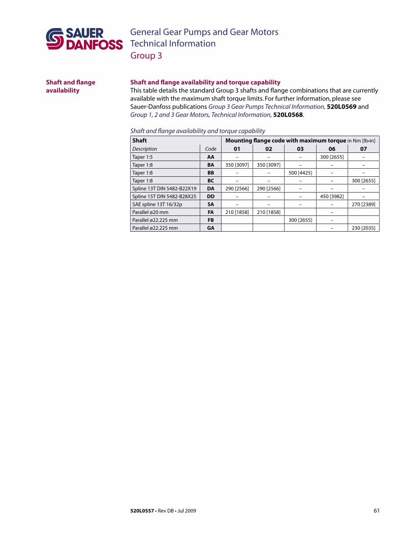
61520L0557 • Rev DB • Jul 2009
General Gear Pumps and Gear MotorsTechnical Information
Shaft and flange availability
Shaft and flange availability and torque capabilityThis table details the standard Group 3 shafts and flange combinations that are currently available with the maximum shaft torque limits. For further information, please see Sauer-Danfoss publications Group 3 Gear Pumps Technical Information, 520L0569 and Group 1, 2 and 3 Gear Motors, Technical Information, 520L0568.
Shaft and flange availability and torque capabilityShaft Mounting flange code with maximum torque in Nm [lb•in]
Description Code 01 02 03 06 07Taper 1:5 AA – – – 300 [2655] –Taper 1:8 BA 350 [3097] 350 [3097] – – –Taper 1:8 BB – – 500 [4425] – –Taper 1:8 BC – – – – 300 [2655]Spline 13T DIN 5482-B22X19 DA 290 [2566] 290 [2566] – – –Spline 15T DIN 5482-B28X25 DD – – – 450 [3982] –SAE spline 13T 16/32p SA – – – – 270 [2389]Parallel ø20 mm FA 210 [1858] 210 [1858] –Parallel ø22.225 mm FB 300 [2655] –Parallel ø22.225 mm GA – 230 [2035]
Group 3
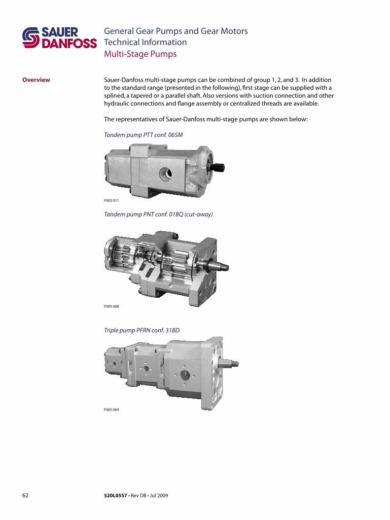
62 520L0557 • Rev DB • Jul 2009
General Gear Pumps and Gear MotorsTechnical Information
Sauer-Danfoss multi-stage pumps can be combined of group 1, 2, and 3. In addition tothestandardrange(presentedinthefollowing),firststagecanbesuppliedwithasplined, a tapered or a parallel shaft. Also versions with suction connection and other hydraulic connections and flange assembly or centralized threads are available.
The representatives of Sauer-Danfoss multi-stage pumps are shown below:
Tandem pump PTT conf. 06SM
Multi-Stage Pumps
Overview
F005 011
F005 069
Triple pump PFRN conf. 31BD
Tandem pump PNT conf. 01BQ (cut-away)
F005 068
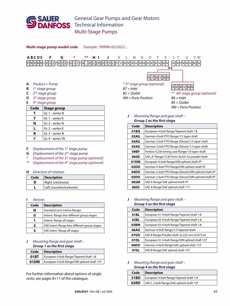
63520L0557 • Rev DB • Jul 2009
General Gear Pumps and Gear MotorsTechnical Information
Multi-stage pump model code
Multi-Stage Pumps
A B C D E F G * ** H I J K L M N O P R S T U V WP R R N N – 0 2 2 / 0 2 2 / 0 1 7 / 4 , 0 L 0 0 7 S L P 3 B B B A N N B B B A N N N N / N N N N N
Example: PRRNN-022/022/ ...
B 7 B 5 N N
* 3rd stage group (optional)B7 = InletB5 = OutletNN = Ports Position
** 4th stage group (optional)B6 = InletB5 = OutletNN = Ports Position
B 6 B 5 N N
J Mounting flange and gear shaft – Group 2 as the first stage
Code Description01BQ European 4 bolt flange/Tapered shaft 1:8
02AG German 4 bolt PTO flange/1:5 taper shaft
04AG German 2 bolt PTO flange (Deutz)/1:5 taper shaft
05AG German 2 bolt PTO flange (Deutz)/1:5 taper shaft
09BY Perkins 4.236 timing case flange/1:8 taper shaft
06GE SAE „A“ flange/15.875mm [0.625 in] parallel shaft
01DM European 4-bolt flange/DIN splined shaft 9T
02DO German 4-bolt PTO flange/DIN splined shaft 9T
04DO German 2-bolt PTO flange (Deutz)/DIN splined shaft 9T
05DO German 2-bolt PTO flange (Deutz)/DIN splined shaft 9T
06SM SAE A flange/SAE splined shaft 9T
06SS SAE A flange/SAE splined shaft 11T
J Mounting flange and gear shaft – Group 3 as the first stage
Code Description01BL European 01 4-bolt flange/Tapered shaft 1:8
02BL European 02 4-bolt flange/Tapered shaft 1:8
03BM European 03 4-bolt flange/Tapered shaft 1:8
06AG German 4-bolt flange/1:5 Tapered shaft
07GD SAE B flange/Parallel shaft 22.225 mm [0.875 in]
01DL European 01 4-bolt flange/DIN splined shaft 13T
06DO German 4-bolt flange/SAE splined shaft 15T
07SL SAE B flange/SAE splined shaft 13T
J Mounting flange and gear shaft – Group 4 as the first stage
Code Description31BD European 4-bolt flange/Tapered shaft 1:8
02RD SAE C 2-bolt flange/SAE splined shaft 14T
For further information about options of single units, see pages 8÷11 of the catalogue.
A Product = PumpB 1st stage groupC 2nd stage groupD 3rd stage groupE 4th stage group
Code Stage groupT Gr. 1 - series N
Y Gr. 1 - series K
N Gr. 2 - series N
L Gr. 2 - series K
R Gr. 3 - series N
F Gr. 4 - series TA
F Displacement of the 1st stage pumpG Displacement of the 2nd stage pump* Displacement of the 3rd stage pump (optional)** Displacement of the 4th stage pump (optional)
H Direction of rotationCode Description
R Right(clockwise)
L Left(counterclockwise)
I Version Code Description
N Standard (w/o interm.flange)
0 Interm. flange btw different group stages
1 Interm. flange all stages
2 SAE intem. flange btw different group stages
S SAE intem. flange all stages
J Mounting flange and gear shaft – Group 1 as the first stage
Code Description01BT European 4 bolt flange/Tapered shaft 1:8
01DM European 4 bolt flange/DIN splined shaft 15T
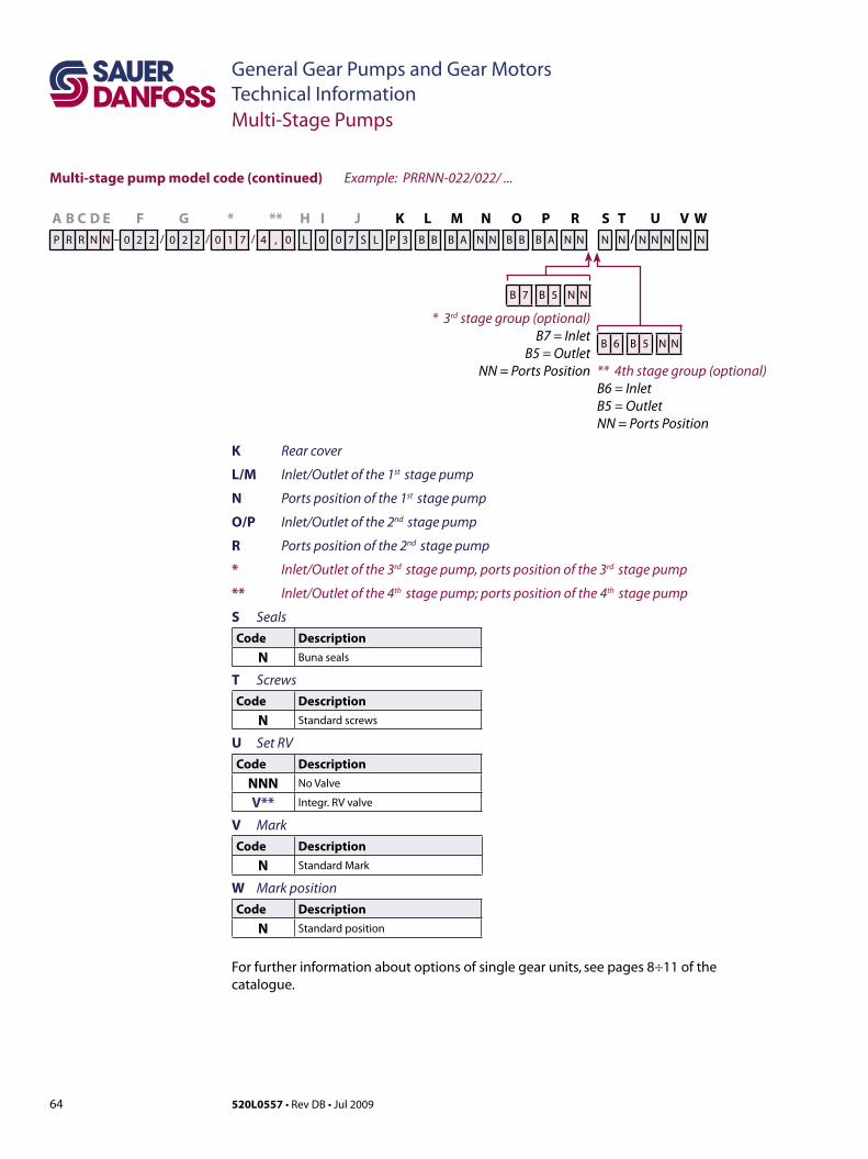
64 520L0557 • Rev DB • Jul 2009
General Gear Pumps and Gear MotorsTechnical InformationMulti-Stage Pumps
A B C D E F G * ** H I J K L M N O P R S T U V WP R R N N – 0 2 2 / 0 2 2 / 0 1 7 / 4 , 0 L 0 0 7 S L P 3 B B B A N N B B B A N N N N / N N N N N
Example: PRRNN-022/022/ ...
B 7 B 5 N N
* 3rd stage group (optional)B7 = Inlet
B5 = OutletNN = Ports Position ** 4th stage group (optional)
B6 = InletB5 = OutletNN = Ports Position
B 6 B 5 N N
Multi-stage pump model code (continued)
K Rear cover
L/M Inlet/Outlet of the 1st stage pump
N Ports position of the 1st stage pump
O/P Inlet/Outlet of the 2nd stage pump
R Ports position of the 2nd stage pump
* Inlet/Outlet of the 3rd stage pump, ports position of the 3rd stage pump
** Inlet/Outlet of the 4th stage pump; ports position of the 4th stage pump
S SealsCode Description
N Buna seals
T ScrewsCode Description
N Standard screws
U Set RVCode Description
NNN No Valve
V** Integr. RV valve
V MarkCode Description
N Standard Mark
W Mark positionCode Description
N Standard position
For further information about options of single gear units, see pages 8÷11 of the catalogue.
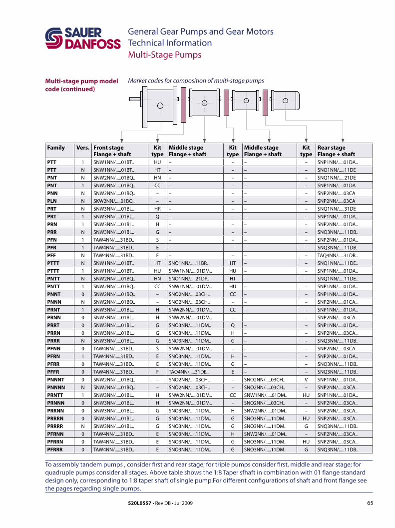
65520L0557 • Rev DB • Jul 2009
General Gear Pumps and Gear MotorsTechnical Information
Market codes for composition of multi-stage pumpsMulti-stage pump model code (continued)
Multi-Stage Pumps
Family Vers. Front stageFlange + shaft
Kit type
Middle stageFlange + shaft
Kit type
Middle stageFlange + shaft
Kit type
Rear stageFlange + shaft
PTT 1 SNW1NN/.....01BT.. HU – – – – SNP1NN/.....01DA..PTT N SNW1NN/.....01BT.. HT – – – – SNQ1NN/.....11DEPNT N SNW2NN/.....01BQ.. HN – – – – SNQ1NN/.....21DEPNT 1 SNW2NN/.....01BQ.. CC – – – – SNP1NN/.....01DAPNN N SNW2NN/.....01BQ.. – – – – – SNP2NN/.....03CAPLN N SKW2NN/.....01BQ.. – – – – – SNP2NN/.....03CAPRT N SNW3NN/.....01BL.. HR – – – – SNQ1NN/.....31DEPRT 1 SNW3NN/.....01BL.. Q – – – – SNP1NN/.....01DA..PRN 1 SNW3NN/.....01BL.. H – – – – SNP2NN/.....01DA..PRR N SNW3NN/.....01BL.. G – – – – SNQ3NN/.....11DB..PFN 1 TAW4NN/.....31BD.. S – – – – SNP2NN/.....01DA..PFR 1 TAW4NN/.....31BD.. E – – – – SNQ3NN/.....11DB..PFF N TAW4NN/.....31BD.. F – – – – TAQ4NN/.....31DB..PTTT N SNW1NN/.....01BT.. HT SNO1NN/.....11BP.. HT – – SNQ1NN/.....11DE..PTTT 1 SNW1NN/.....01BT.. HU SNW1NN/.....01DM.. HU – – SNP1NN/.....01DA..PNTT N SNW2NN/.....01BQ.. HN SNO1NN/.....21DP.. HT – – SNQ1NN/.....11DE..PNTT 1 SNW2NN/.....01BQ.. CC SNW1NN/.....01DM.. HU – – SNP1NN/.....01DA..PNNT 0 SNW2NN/.....01BQ.. – SNO2NN/.....03CH.. CC – – SNP1NN/.....01DA..PNNN N SNW2NN/.....01BQ.. – SNO2NN/.....03CH.. – – – SNP2NN/.....01CA..PRNT 1 SNW3NN/.....01BL.. H SNW2NN/.....01DM.. CC – – SNP1NN/.....01DA..PRNN 0 SNW3NN/.....01BL.. H SNW2NN/.....01DM.. – – – SNP2NN/.....03CA..PRRT 0 SNW3NN/.....01BL.. G SNO3NN/.....11DM.. Q – – SNP1NN/.....01DA..PRRN 0 SNW3NN/.....01BL.. G SNO3NN/.....11DM.. H – – SNP2NN/.....03CA..PRRR N SNW3NN/.....01BL.. G SNO3NN/.....11DM.. G – – SNQ3NN/.....11DB..PFNN 0 TAW4NN/.....31BD.. S SNW2NN/.....01DM.. – – – SNP2NN/.....03CA..PFRN 1 TAW4NN/.....31BD.. E SNO3NN/.....11DM.. H – – SNP2NN/.....01DA..PFRR 0 TAW4NN/.....31BD.. E SNO3NN/.....11DM.. G – – SNQ3NN/.....11DB..PFFR 0 TAW4NN/.....31BD.. F TAO4NN/.....31DE.. E – – SNQ3NN/.....11DB..PNNNT 0 SNW2NN/.....01BQ.. – SNO2NN/.....03CH.. – SNO2NN/.....03CH.. V SNP1NN/.....01DA..PNNNN N SNW2NN/.....01BQ.. – SNO2NN/.....03CH.. – SNO2NN/.....03CH.. – SNP2NN/.....03CA..PRNTT 1 SNW3NN/.....01BL.. H SNW2NN/.....01DM.. CC SNW1NN/.....01DM.. HU SNP1NN/.....01DA..PRNNN 0 SNW3NN/.....01BL.. H SNW2NN/.....01DM.. – SNO2NN/.....03CH.. – SNP2NN/.....03CA..PRRNN 0 SNW3NN/.....01BL.. G SNO3NN/.....11DM.. H SNW2NN/.....01DM.. – SNP2NN/.....03CA..PRRRN 0 SNW3NN/.....01BL.. G SNO3NN/.....11DM.. G SNO3NN/.....11DM.. HU SNP2NN/.....03CA..PRRRR N SNW3NN/.....01BL.. G SNO3NN/.....11DM.. G SNO3NN/.....11DM.. G SNQ3NN/.....11DB..PFRNN 0 TAW4NN/.....31BD.. E SNO3NN/.....11DM.. H SNW2NN/.....01DM.. – SNP2NN/.....03CA..PFRRN 0 TAW4NN/.....31BD.. E SNO3NN/.....11DM.. G SNO3NN/.....11DM.. HU SNP2NN/.....03CA..PFRRR 0 TAW4NN/.....31BD.. E SNO3NN/.....11DM.. G SNO3NN/.....11DM.. G SNQ3NN/.....11DB..
To assembly tandem pumps , consider first and rear stage; for triple pumps consider first, middle and rear stage; for quadruple pumps consider all stages. Above table shows the 1:8 Taper sfhaft in combination with 01 flange standard design only, corresponding to 1:8 taper shaft of single pump.For different configurations of shaft and front flange see the pages regarding single pumps.
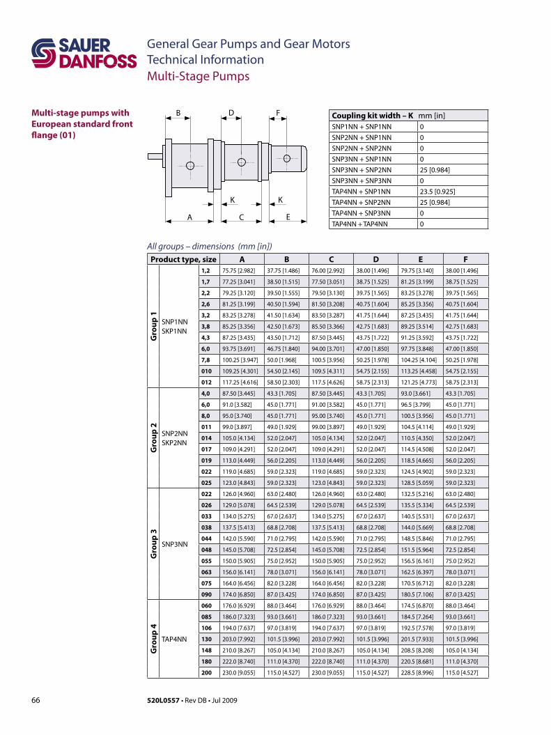
66 520L0557 • Rev DB • Jul 2009
General Gear Pumps and Gear MotorsTechnical Information
Multi-stage pumps with European standard front flange (01)
Multi-Stage Pumps
B D F
A C E
K K
All groups – dimensions (mm [in])Product type, size A B C D E F
Gro
up 1
SNP1NNSKP1NN
1,2 75.75 [2.982] 37.75 [1.486] 76.00 [2.992] 38.00 [1.496] 79.75 [3.140] 38.00 [1.496]
1,7 77.25 [3.041] 38.50 [1.515] 77.50 [3.051] 38.75 [1.525] 81.25 [3.199] 38.75 [1.525]
2,2 79.25 [3.120] 39.50 [1.555] 79.50 [3.130] 39.75 [1.565] 83.25 [3.278] 39.75 [1.565]
2,6 81.25 [3.199] 40.50 [1.594] 81.50 [3.208] 40.75 [1.604] 85.25 [3.356] 40.75 [1.604]
3,2 83.25 [3.278] 41.50 [1.634] 83.50 [3.287] 41.75 [1.644] 87.25 [3.435] 41.75 [1.644]
3,8 85.25 [3.356] 42.50 [1.673] 85.50 [3.366] 42.75 [1.683] 89.25 [3.514] 42.75 [1.683]
4,3 87.25 [3.435] 43.50 [1.712] 87.50 [3.445] 43.75 [1.722] 91.25 [3.592] 43.75 [1.722]
6,0 93.75 [3.691] 46.75 [1.840] 94.00 [3.701] 47.00 [1.850] 97.75 [3.848] 47.00 [1.850]
7,8 100.25 [3.947] 50.0 [1.968] 100.5 [3.956] 50.25 [1.978] 104.25 [4.104] 50.25 [1.978]
010 109.25 [4.301] 54.50 [2.145] 109.5 [4.311] 54.75 [2.155] 113.25 [4.458] 54.75 [2.155]
012 117.25 [4.616] 58.50 [2.303] 117.5 [4.626] 58.75 [2.313] 121.25 [4.773] 58.75 [2.313]
Gro
up 2
SNP2NNSKP2NN
4,0 87.50 [3.445] 43.3 [1.705] 87.50 [3.445] 43.3 [1.705] 93.0 [3.661] 43.3 [1.705]
6,0 91.0 [3.582] 45.0 [1.771] 91.00 [3.582] 45.0 [1.771] 96.5 [3.799] 45.0 [1.771]
8,0 95.0 [3.740] 45.0 [1.771] 95.00 [3.740] 45.0 [1.771] 100.5 [3.956] 45.0 [1.771]
011 99.0 [3.897] 49.0 [1.929] 99.00 [3.897] 49.0 [1.929] 104.5 [4.114] 49.0 [1.929]
014 105.0 [4.134] 52.0 [2.047] 105.0 [4.134] 52.0 [2.047] 110.5 [4.350] 52.0 [2.047]
017 109.0 [4.291] 52.0 [2.047] 109.0 [4.291] 52.0 [2.047] 114.5 [4.508] 52.0 [2.047]
019 113.0 [4.449] 56.0 [2.205] 113.0 [4.449] 56.0 [2.205] 118.5 [4.665] 56.0 [2.205]
022 119.0 [4.685] 59.0 [2.323] 119.0 [4.685] 59.0 [2.323] 124.5 [4.902] 59.0 [2.323]
025 123.0 [4.843] 59.0 [2.323] 123.0 [4.843] 59.0 [2.323] 128.5 [5.059] 59.0 [2.323]
Gro
up 3
SNP3NN
022 126.0 [4.960] 63.0 [2.480] 126.0 [4.960] 63.0 [2.480] 132.5 [5.216] 63.0 [2.480]
026 129.0 [5.078] 64.5 [2.539] 129.0 [5.078] 64.5 [2.539] 135.5 [5.334] 64.5 [2.539]
033 134.0 [5.275] 67.0 [2.637] 134.0 [5.275] 67.0 [2.637] 140.5 [5.531] 67.0 [2.637]
038 137.5 [5.413] 68.8 [2.708] 137.5 [5.413] 68.8 [2.708] 144.0 [5.669] 68.8 [2.708]
044 142.0 [5.590] 71.0 [2.795] 142.0 [5.590] 71.0 [2.795] 148.5 [5.846] 71.0 [2.795]
048 145.0 [5.708] 72.5 [2.854] 145.0 [5.708] 72.5 [2.854] 151.5 [5.964] 72.5 [2.854]
055 150.0 [5.905] 75.0 [2.952] 150.0 [5.905] 75.0 [2.952] 156.5 [6.161] 75.0 [2.952]
063 156.0 [6.141] 78.0 [3.071] 156.0 [6.141] 78.0 [3.071] 162.5 [6.397] 78.0 [3.071]
075 164.0 [6.456] 82.0 [3.228] 164.0 [6.456] 82.0 [3.228] 170.5 [6.712] 82.0 [3.228]
090 174.0 [6.850] 87.0 [3.425] 174.0 [6.850] 87.0 [3.425] 180.5 [7.106] 87.0 [3.425]
Gro
up 4
TAP4NN
060 176.0 [6.929] 88.0 [3.464] 176.0 [6.929] 88.0 [3.464] 174.5 [6.870] 88.0 [3.464]
085 186.0 [7.323] 93.0 [3.661] 186.0 [7.323] 93.0 [3.661] 184.5 [7.264] 93.0 [3.661]
106 194.0 [7.637] 97.0 [3.819] 194.0 [7.637] 97.0 [3.819] 192.5 [7.578] 97.0 [3.819]
130 203.0 [7.992] 101.5 [3.996] 203.0 [7.992] 101.5 [3.996] 201.5 [7.933] 101.5 [3.996]
148 210.0 [8.267] 105.0 [4.134] 210.0 [8.267] 105.0 [4.134] 208.5 [8.208] 105.0 [4.134]
180 222.0 [8.740] 111.0 [4.370] 222.0 [8.740] 111.0 [4.370] 220.5 [8.681] 111.0 [4.370]
200 230.0 [9.055] 115.0 [4.527] 230.0 [9.055] 115.0 [4.527] 228.5 [8.996] 115.0 [4.527]
Coupling kit width – K mm [in]SNP1NN + SNP1NN 0SNP2NN + SNP1NN 0SNP2NN + SNP2NN 0SNP3NN + SNP1NN 0SNP3NN + SNP2NN 25 [0.984]SNP3NN + SNP3NN 0TAP4NN + SNP1NN 23.5 [0.925]TAP4NN + SNP2NN 25 [0.984]TAP4NN + SNP3NN 0TAP4NN + TAP4NN 0
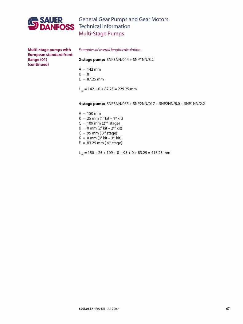
67520L0557 • Rev DB • Jul 2009
General Gear Pumps and Gear MotorsTechnical Information
Examples of overall lenght calculation:
2-stage pump: SNP3NN/044+SNP1NN/3,2
A = 142 mmK = 0E = 87.25 mm
Ltot
=142+0+87.25=229.25mm
4-stage pump: SNP3NN/055+SNP2NN/017+SNP2NN/8,0+SNP1NN/2,2
A = 150 mmK= 25mm(1°kit–1st kit)C= 109mm(2nd stage)K= 0mm(2°kit–2nd kit)C= 95mm(3rd stage)K= 0mm(3°kit–3rd kit)E= 83.25mm(4th stage)
Ltot
=150+25+109+0+95+0+83.25=413.25mm
Multi-stage pumps with European standard front flange (01)(continued)
Multi-Stage Pumps
Sauer-Danfoss Mobile Power and Control Systems– Market Leaders Worldwide
Sauer-Danfoss is a comprehensive supplier providing complete systems to the global mobile market.
Sauer-Danfoss serves markets such as agriculture, construction, road building, material handling, municipal, forestry, turf care, and many others.
Weofferourcustomersoptimumsolutionsfortheirneedsanddevelop new products and systems in close cooperation and partner ship with them.
Sauer-Danfoss specializes in integrating a full range of system components to provide vehicle designers with the most advanced total system design.
Sauer-Danfoss provides comprehensive worldwide service for its products through an extensive network of Global Service Partners strategically located in all parts of the world.
Sauer-Danfoss (US) Company2800 East 13th StreetAmes, IA 50010, USAPhone: +1 515 239 6000Fax: +1 515 239 6618
Sauer-Danfoss GmbH & Co. OHGPostfach 2460, D-24531 NeumünsterKrokamp 35, D-24539 Neumünster, GermanyPhone: +49 4321 871-0Fax: +49 4321 871 122
Sauer-Danfoss ApSDK-6430 Nordborg, DenmarkPhone: +45 7488 4444Fax: +45 7488 4400
Sauer-Danfoss-Daikin LTDSannomiya Grand Bldg. 8F2-2-21 Isogami-dori, Chuo-kuKobe, Hyogo 651-0086, JapanPhone: +81 78 231 5001Fax: +81 78 231 5004
www.sauer-danfoss.com
Local address:
Our Products
Open circuit axial piston pumps
Gear pumps and motors
Fan drive systems
Closed circuit axial piston pumps and motors
Bent axis motors
Hydrostatic transmissions
Transit mixer drives
Hydrostatic transaxles
Electrohydraulics
Integrated systems
Microcontrollers and software
PLUS+1™ GUIDE
Displays
Joysticks and control handles
Sensors
Orbital motors
Inverters
Electrohydraulic power steering
Hydraulic power steering
Hydraulic integrated circuits (HIC)
Cartridge valves
Directional spool valves
Proportional valves
520L0557 • Rev DB • Jul 2009