Embed Size (px)
Citation preview
This paper is included in the Proceedings of the 16th USENIX Symposium on Networked Systems
Design and Implementation (NSDI ’19).February 26–28, 2019 • Boston, MA, USA
ISBN 978-1-931971-49-2
Open access to the Proceedings of the 16th USENIX Symposium on Networked Systems
Design and Implementation (NSDI ’19) is sponsored by
Hydra: a federated resource manager for data-center scale analytics
Carlo Curino, Subru Krishnan, and Konstantinos Karanasos, Microsoft; Sriram Rao, Facebook; Giovanni M. Fumarola, Botong Huang, Kishore Chaliparambil,
Arun Suresh, Young Chen, Solom Heddaya, Roni Burd, Sarvesh Sakalanaga, Chris Douglas, Bill Ramsey, and Raghu Ramakrishnan, Microsoft
https://www.usenix.org/conference/nsdi19/presentation/curino
Hydra: a federated resource manager for data-center scale analytics
Carlo Curino Subru Krishnan Konstantinos Karanasos Sriram Rao∗
Giovanni M. Fumarola Botong Huang Kishore Chaliparambil Arun Suresh
Young Chen Solom Heddaya Roni Burd Sarvesh Sakalanaga Chris Douglas
Bill Ramsey Raghu Ramakrishnan
Microsoft
Abstract
Microsoft’s internal data lake processes exabytes of data over
millions of cores daily on behalf of thousands of tenants.
Scheduling this workload requires 10× to 100× more de-
cisions per second than existing, general-purpose resource
management frameworks are known to handle. In 2013, we
were faced with a growing demand for workload diversity
and richer sharing policies that our legacy system could not
meet. In this paper, we present Hydra, the resource manage-
ment infrastructure we built to meet these requirements.
Hydra leverages a federated architecture, in which a
cluster is comprised of multiple, loosely coordinating sub-
clusters. This allows us to scale by delegating placement of
tasks on machines to each sub-cluster, while centrally coor-
dinating only to ensure that tenants receive the right share
of resources. To adapt to changing workload and cluster
conditions promptly, Hydra’s design features a control plane
that can push scheduling policies across tens of thousands of
nodes within seconds. This feature combined with the feder-
ated design allows for great agility in developing, evaluating,
and rolling out new system behaviors.
We built Hydra by leveraging, extending, and contributing
our code to Apache Hadoop YARN. Hydra is currently the
primary big-data resource manager at Microsoft. Over the
last few years, Hydra has scheduled nearly one trillion tasks
that manipulated close to a Zettabyte of production data.
1 Introduction
As organizations amass and analyze unprecedented amounts
of data, dedicated data silos are being abandoned in favor
of more cost-effective, shared data environments, such as
private or public clouds. Sharing a unified infrastructure
across all analytics frameworks and across tenants avoids the
resource fragmentation associated with operating multiple
smaller clusters [37] and lowers data access barriers. This
∗The work was done while the author was at Microsoft; currently em-
ployed by Facebook.
is the vision of the data lake: empower every data scientist
to leverage all available hardware resources to process any
dataset using any framework seamlessly [26]. To realize this
vision, cloud vendors and large enterprises are building and
operating data-center scale clusters [7, 15, 37].
At Microsoft, we operate one of the biggest data lakes,
whose underlying compute capacity comprises hundreds of
thousands of machines [7, 26]. Until recently, our clusters
were dedicated to a single application framework, namely
Scope [44], and were managed by our custom distributed
scheduler, Apollo [7]. This architecture scaled to clus-
ters1 of more than 50k nodes, supported many thousands
of scheduling decisions per second, and achieved state-
of-the-art resource utilization. New requirements to share
the same physical infrastructure across diverse application
frameworks (both internal and popular open-source ones)
clashed with the core assumption of our legacy architecture
that all jobs had homogeneous scheduling patterns. Fur-
ther, teams wanted more control over how idle capacity was
shared, and system operators needed more flexibility while
maintaining the fleet. This motivated us to build Hydra,
a resource management framework that today powers the
Microsoft-wide data lake. Hydra is the scheduling counter-
part of the storage layer presented in [26].
Hydra matches the scalability and utilization of our legacy
system, while supporting diverse workloads, stricter shar-
ing policies, and testing of scheduling policies at scale (§2).
This is achieved by means of a new federated architecture,
in which a collection of loosely coupled sub-clusters coordi-
nates to provide the illusion of a single massive cluster (§3).
This design allows us to scale the two underlying problems
of placement and share-determination separately. Placement
of tasks on physical nodes can be scaled by running it in-
dependently at each sub-cluster, with only local visibility.
On the other hand, share-determination (i.e., choosing how
many resources each tenant should get) requires global vis-
1By cluster we refer to a logical collection of servers that is used for
quota management and security purposes. A cluster can span data centers,
but each job has to fit into a cluster’s boundaries.
USENIX Association 16th USENIX Symposium on Networked Systems Design and Implementation 177
ibility to respect sharing policies without pinning tenants to
sub-clusters. We scale share-determination by operating on
an aggregate view of the cluster state.
At the heart of Hydra lie scheduling policies that deter-
mine the behavior of the system’s core components. Given
our diverse workloads and rapidly changing cluster condi-
tions, we designed Hydra’s control plane to allow us to dy-
namically “push” policies. Cluster operators and automated
systems can change Hydra’s scheduling behaviors of a 50k
node cluster within seconds, without redeploying our plat-
form. This agility allowed us to experiment with policies and
to cope with outages swiftly. We discuss several policies, and
show experimentally some of their trade-offs, in §4.
This federated architecture, combined with flexible poli-
cies, also means that we can tune each sub-cluster differ-
ently, e.g., to optimize interactive query latencies, scale to
many nodes, operate on virtualized resources, or A/B test
new scheduling behaviors. Hydra makes this transparent
to users and applications, which perceive the resources as
a continuum, and allows operators to mix or segregate ten-
ants and behaviors in a dynamic, lightweight fashion. The
architecture also enables several additional scenarios by al-
lowing individual jobs to span sub-clusters: owned by differ-
ent organizations, equipped with specialized hardware (e.g.,
GPUs or FPGAs), or located in separate data centers or re-
gions [8]. In addition to the flexibility offered to users who
submit jobs, these capabilities are invaluable for operators of
the data lake, enabling them to manage complex workloads
during system upgrades, capacity changes, or outages.
Figure 1: Hydra deployment in our production fleet (hun-
dreds of thousands of nodes) over time.
An additional contribution of this paper is an open-source
implementation of our production-hardened system (§5), as
well as a summary of lessons learned during a large-scale
migration from our legacy system. The migration consisted
of a carefully choreographed in-place migration process of
a massive production environment (§2), while the entirety of
Microsoft depended on it. This journey was not without chal-
lenges, as we describe in §6. Fig. 1 shows the deployment of
Hydra across our fleet over time. Since we started deploy-
ing it, Hydra has scheduled and managed nearly one trillion
tasks that processed close to a Zettabyte of data. We report
on our production deployments in §7, explicitly comparing
its performance with our legacy system [7].
Apart from the new material presented in this paper, Hy-
dra draws from several existing research efforts [7, 9, 11,
17, 19, 18, 27, 36]. In §8, we put Hydra in context with its
related work, mostly focusing on production-ready resource
managers [7, 15, 20, 36, 37].
2 Background and Requirements
At Microsoft we operate a massive data infrastructure, pow-
ering both our public cloud and our internal offerings. Next,
we discuss the peculiarities of our internal clusters and work-
load environments (§2.1), as well as how they affect our re-
quirements for resource management (§2.2) and our design
choices in building Hydra (§2.3).
2.1 Background on our Environment
Cluster environment. Tab. 1 summarizes various dimen-
sions of our big-data fleet.
Dimension Description Size
Daily Data I/O Total bytes processed daily >1EB
Fleet Size Number of servers in the fleet >250k
Cluster Size Number of servers per cluster >50k
# Deployments Platform deployments monthly 1-10
Table 1: Microsoft cluster environments.
Our target cluster environments are very large in scale and
heterogeneous, including several generations of machines
and specialized hardware (e.g., GPU/FPGA). Our system
must also be compatible with multiple hardware manage-
ment and deployment platforms [16, 5]. Thus, we make
minimal assumptions on the underlying infrastructure and
develop a control-plane to push configurations and policies.
We observe up to 5% machine unavailability in our clus-
ters due to various events, such as hardware failures, OS
upgrades, and security patches. Our resource management
substrate should remain highly available despite high hard-
ware/software churn.
Sharing across tenants. As shown in Tab. 2, our clusters
are shared across thousands of users. Users have access to
hierarchical queues, which are logical constructs to define
storage and compute quotas. The queue hierarchy loosely
follows organizational and project boundaries.
Dimension Description Size
# Users Number of users >10k
# Queues Number of (hierarchical) queues >5k
Hierarchy depth Levels in the queue hierarchy 5-12
Priority levels Number of priority levels (avg/max) 10/1000
Table 2: Tenant details in Microsoft clusters.
In our setting, tenants pay for guaranteed compute capac-
ity (quota) as a means to achieve predictable execution [17].
Tenants typically provision their production quotas for their
178 16th USENIX Symposium on Networked Systems Design and Implementation USENIX Association
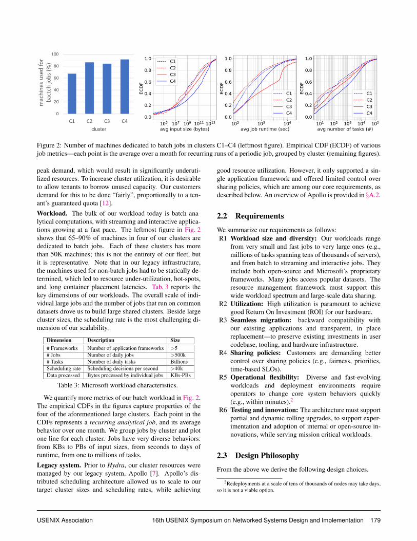
Figure 2: Number of machines dedicated to batch jobs in clusters C1–C4 (leftmost figure). Empirical CDF (ECDF) of various
job metrics—each point is the average over a month for recurring runs of a periodic job, grouped by cluster (remaining figures).
peak demand, which would result in significantly underuti-
lized resources. To increase cluster utilization, it is desirable
to allow tenants to borrow unused capacity. Our customers
demand for this to be done “fairly”, proportionally to a ten-
ant’s guaranteed quota [12].
Workload. The bulk of our workload today is batch ana-
lytical computations, with streaming and interactive applica-
tions growing at a fast pace. The leftmost figure in Fig. 2
shows that 65–90% of machines in four of our clusters are
dedicated to batch jobs. Each of these clusters has more
than 50K machines; this is not the entirety of our fleet, but
it is representative. Note that in our legacy infrastructure,
the machines used for non-batch jobs had to be statically de-
termined, which led to resource under-utilization, hot-spots,
and long container placement latencies. Tab. 3 reports the
key dimensions of our workloads. The overall scale of indi-
vidual large jobs and the number of jobs that run on common
datasets drove us to build large shared clusters. Beside large
cluster sizes, the scheduling rate is the most challenging di-
mension of our scalability.
Dimension Description Size
# Frameworks Number of application frameworks >5
# Jobs Number of daily jobs >500k
# Tasks Number of daily tasks Billions
Scheduling rate Scheduling decisions per second >40k
Data processed Bytes processed by individual jobs KBs-PBs
Table 3: Microsoft workload characteristics.
We quantify more metrics of our batch workload in Fig. 2.
The empirical CDFs in the figures capture properties of the
four of the aforementioned large clusters. Each point in the
CDFs represents a recurring analytical job, and its average
behavior over one month. We group jobs by cluster and plot
one line for each cluster. Jobs have very diverse behaviors:
from KBs to PBs of input sizes, from seconds to days of
runtime, from one to millions of tasks.
Legacy system. Prior to Hydra, our cluster resources were
managed by our legacy system, Apollo [7]. Apollo’s dis-
tributed scheduling architecture allowed us to scale to our
target cluster sizes and scheduling rates, while achieving
good resource utilization. However, it only supported a sin-
gle application framework and offered limited control over
sharing policies, which are among our core requirements, as
described below. An overview of Apollo is provided in §A.2.
2.2 Requirements
We summarize our requirements as follows:
R1 Workload size and diversity: Our workloads range
from very small and fast jobs to very large ones (e.g.,
millions of tasks spanning tens of thousands of servers),
and from batch to streaming and interactive jobs. They
include both open-source and Microsoft’s proprietary
frameworks. Many jobs access popular datasets. The
resource management framework must support this
wide workload spectrum and large-scale data sharing.
R2 Utilization: High utilization is paramount to achieve
good Return On Investment (ROI) for our hardware.
R3 Seamless migration: backward compatibility with
our existing applications and transparent, in place
replacement—to preserve existing investments in user
codebase, tooling, and hardware infrastructure.
R4 Sharing policies: Customers are demanding better
control over sharing policies (e.g., fairness, priorities,
time-based SLOs).
R5 Operational flexibility: Diverse and fast-evolving
workloads and deployment environments require
operators to change core system behaviors quickly
(e.g., within minutes).2
R6 Testing and innovation: The architecture must support
partial and dynamic rolling upgrades, to support exper-
imentation and adoption of internal or open-source in-
novations, while serving mission critical workloads.
2.3 Design Philosophy
From the above we derive the following design choices.
2Redeployments at a scale of tens of thousands of nodes may take days,
so it is not a viable option.
USENIX Association 16th USENIX Symposium on Networked Systems Design and Implementation 179
Large shared clusters. Requirements R1/R2 push us to
share large clusters to avoid fragmentation and to support
our largest jobs. Scaling the resource manager becomes key.
General-purpose resource management. R1/R3/R4 force
us to invest in a general-purpose resource management layer,
arbitrating access from multiple frameworks, including the
legacy one, as first class citizens. R3 is at odds with
the frameworks-specific nature of our previous distributed
scheduling solution [7].
Agile infrastructure behavior. R5/R6 rule out custom,
highly scalable, centralized approaches, as integrating
open-source innovations and adapting to different conditions
would become more delicate and require higher engineering
costs. This pushed us towards a federated solution building
upon the community innovation at each sub-cluster.
Aligning with open-source. We chose to implement Hydra
by re-architecting and extending Apache Hadoop YARN [36,
19]. This allows us to leverage YARN’s wide adoption in
companies such as Yahoo!, LinkedIn, Twitter, Uber, Alibaba,
Ebay, and its compatibility with popular frameworks such as
Spark, Hive, Tez, Flink, Cascading, HBase, TensorFlow.
3 Overview of Hydra
We now describe the user model (§3.1) and federated archi-
tecture of Hydra (§3.2), and then present the life-cycle of a
job in our system (§3.3).
3.1 Model of User Interaction
The overall cluster capacity is logically organized into
queues of a given guaranteed capacity, i.e., a configured
amount of physical cluster resources that is dedicated to each
queue.3 Each user has access to one or more queues and can
submit jobs to them. Queues support job priorities, optional
gang semantics (i.e., minimum required parallelism for a
job to launch), as well as many other quota mechanisms,
which we omit for brevity. An important value proposition
of Hydra is to provide users with the illusion of a single
large cluster; the details of how this is realized must not be
exposed.
Jobs are collections of tasks (i.e., processes). Each task
runs within a container, which is a bundle of physical re-
sources (e.g., <RAM,CPU,IOs,...>) on a single worker
node. Containers can be isolated by means of virtual ma-
chines, OS containers, or simple process boundaries. Jobs
may dynamically negotiate access to different amounts of re-
sources, which are taken from the guaranteed capacity of the
queue they are submitted to. This negotiation is done by a
special container: the job’s Application Master (AM).
3Servers are not partitioned among queues but shared dynamically.
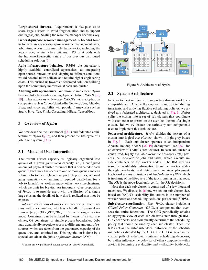
Figure 3: Architecture of Hydra.
3.2 System Architecture
In order to meet our goals of: supporting diverse workloads
compatible with Apache Hadoop, enforcing stricter sharing
invariants, and allowing flexible scheduling policies, we ar-
rived at a federated architecture, depicted in Fig. 3. Hydra
splits the cluster into a set of sub-clusters that coordinate
with each other to present to the user the illusion of a single
cluster. Below, we discuss the various system components
used to implement this architecture.
Federated architecture. Hydra divides the servers of a
cluster into logical sub-clusters, shown in light-gray boxes
in Fig. 3. Each sub-cluster operates as an independent
Apache Hadoop YARN [36, 19] deployment (see §A.1 for
an overview of YARN’s architecture). In each sub-cluster, a
centralized, highly available Resource Manager (RM) gov-
erns the life-cycle of jobs and tasks, which execute in-
side containers on the worker nodes. The RM receives
resource availability information from the worker nodes
through heartbeats, and determines container placement.
Each worker runs an instance of NodeManager (NM) which
is in charge of the life-cycle of the tasks running on that node.
The NM is the node-local enforcer for the RM decisions.
Note that each sub-cluster is comprised of a few thousand
machines. We discuss in §6 how we set our sub-cluster size,
based on YARN’s scalability limitations in the number of
worker nodes and scheduling decisions per second (SDPS).
Sub-cluster coordination. Each Hydra cluster includes a
Global Policy Generator (GPG), a component that over-
sees the entire federation. The GPG periodically obtains
an aggregate view of each sub-cluster’s state through RM–
GPG heartbeats, and dynamically determines the scheduling
policy that should be used by each sub-cluster. Then, the
RMs act as the sub-cluster-local enforcers of the schedul-
ing policies dictated by the GPG. The GPG is never in the
critical path of individual container scheduling decisions,
but rather influence the behavior of other components—this
avoids it becoming a scalability and availability bottleneck.
180 16th USENIX Symposium on Networked Systems Design and Implementation USENIX Association
The StateStore is a highly available, centralized store4 that
contains the authoritative copy of all system configurations
and policies, and allows us to change the system behavior
dynamically. Each component in the system periodically re-
ports liveness to the StateStore through heartbeats, and gets
informed of new policies. The StateStore Proxy is a caching
layer that improves the read-scalability.
Single-cluster illusion. In order to provide users with the
illusion of a single large cluster, we need to hide the pres-
ence of multiple sub-clusters when (i) a job is submitted, and
(ii) an AM requests new resources (containers). To this end,
we introduce layers of indirection through two components,
namely the Router and the AM–RM Proxy. Each Router pro-
vides the users with a single entry point to the overall plat-
form. Routers mediate all interactions between users and
the RMs, dynamically determining the sub-cluster that a job
should be launched in. This will be the “home” sub-cluster,
where the job’s AM will be running. The AM–RM Proxy
is a service that runs at every worker node and translates
AM container requests to asks to one or more RMs. This
allows individual jobs to span sub-clusters. Similar to what
the Router does for external users, the AM–RM Proxy hides
the plurality of RMs and shields the applications from the
system’s internal complexity.
Along with providing a single-cluster illusion, the Router
and AM–RM Proxy components allow us to: (i) mask avail-
ability issues of RMs (an RM failing is masked by rerouting
resource demands to other RMs), (ii) protect RMs from an
excessive number of requests (e.g., coming from malicious
AMs) that could lead to denial-of-service issues, (iii) bal-
ance load among sub-clusters, and (iv) flexibly handle main-
tenance and flighting operations.
Policy-driven design. All scheduling decisions in Hydra are
policy-driven and depend on the policies that the GPG in-
stalls in the various system components. The choice of poli-
cies can significantly change the system’s behavior. In par-
ticular, Routers determine where a job is started (thus affect-
ing job queuing time), AM–RM Proxy shapes the load that
each sub-cluster receives, and RMs determine how requests
from multiple queues are fulfilled. Finally, GPG determines
the share determination, i.e., deciding how many resources
each tenant will get.
Importantly, the GPG is not on the critical path of con-
tainer allocation decisions, but asynchronously updates the
RMs’ scheduling policy. The RMs operate independently,
in accordance with the most recently received policy. Even
if the GPG is not reachable, the RM can continue perform-
ing allocations, which ensures that the cluster remains highly
available and highly utilized. We provide more details about
our policies in §4.
4We provide multiple implementations, including SQL Server, HBase,
and ZooKeeper, depending on the deployment setting.
3.3 Life of a Job
We illustrate the federated architecture of Hydra through the
life-cycle of a job (the corresponding steps are also marked
in Fig. 3).
(1) Job j is submitted to queue q via the Router (1a), which
determines through a policy the sub-cluster that should
be the job’s home, e.g., sub-cluster 1 in Fig. 3 (1b).
(2) The Router records its decision in the StateStore (2a)
and forwards the job submission request to the RM of
the chosen sub-cluster (2b).
(3) The RM performs admission control and determines
when and where to starts the job’s AM (3a). The AM is
launched on a node, e.g., NM25 (3b).
(4) The AM begins requesting containers on nodes (e.g.,
NM60) via the AM–RM Proxy (4a), which consults a
policy to determine the RMs to forward the request and
how to split/merge/modify the requests if needed (4b).
(5) The AM–RM Proxy impersonates the job and contacts
all the RMs required to fulfill the demand, e.g., RM2.
Each job spans as many sub-clusters as needed.
(6) Each RM summarizes its state (usage and demands) and
forwards it to the GPG every few seconds through a sep-
arate heartbeat channel (6a). The GPG follows policies
to determine share-determination in aggregate, and pro-
vides guidance back to the RMs on how to grant access
to resources for different tenants (6b).
(7) The RM uses the most recent policy suggestion from
GPG to allocate tasks on behalf of the AM, e.g., Task1
on NM60 (7a).5 The task is launched, and can begin
its computation and to communicate directly with the
AM (7b).
4 Scheduling Policies
We now describe the policies governing Hydra. Our main
goal is to scale placement (§4.1) and share-determination
(§4.2) to large numbers of nodes and scheduling decisions
per second.
4.1 Placement
Placement of containers on machines affects locality (e.g.,
between computations and their input data or their hardware
preferences like GPU or FPGA), load balancing, and fault
tolerance of jobs in Hydra. We scale placement by paral-
lelizing decision-making—each sub-cluster performs place-
ment decisions independently. The following policies, asso-
ciated with different system components (see §3), determine
the routing of requests and allocation of containers.
Router policies assign jobs’ Application Masters (AMs) to
sub-clusters. Since AMs consume limited resources and typ-
5Note that 7a could happen before 6a-6b, if the previous round of allo-
cation policies from GPG allow the RM to allocate more for queue q.
USENIX Association 16th USENIX Symposium on Networked Systems Design and Implementation 181
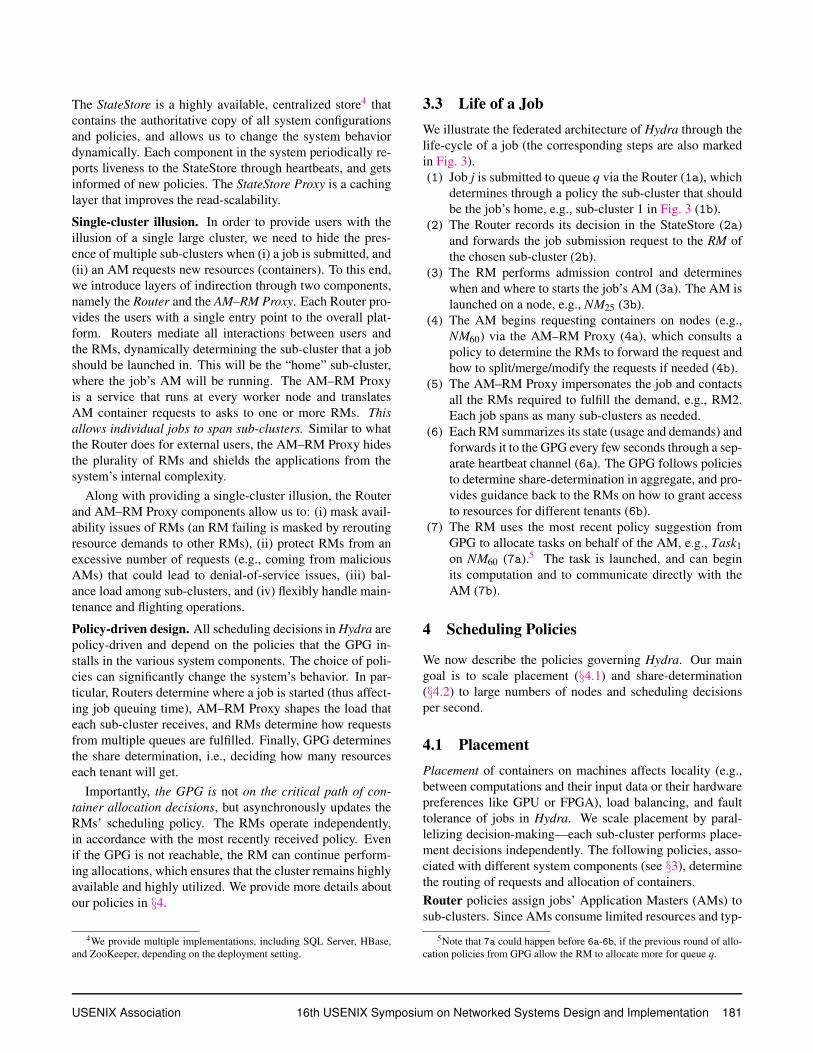
Figure 4: Placement quality over a period of one month:
>97% of requests on average are placed on the preferred
node or rack.
ically have no locality requirements, Router policies focus on
fault tolerance by spreading AMs across sub-clusters. To this
end, the Router retrieves the current sub-cluster state (e.g.,
active RM’s URL, current utilization, outstanding demand)
from the StateStore (cached for performance). The Router
itself is fully stateless and thus is horizontally scalable. We
achieve fault tolerance by deploying multiple Router in-
stances behind a load balancer. Internally the Router adopts
an interceptor design pattern, which allows us to dynamically
change and configure its policies.
AM–RM Proxy policies affect the placement of all non-AM
containers. We experimented with various policies in our
production environments, trying to strike a balance between
locality.6 load balancing, and fault tolerance. The policy
we settled for tries to optimize for locality preferences by
forwarding requests to the RM that owns the node speci-
fied in the request. Our policy extends the notion of delay-
scheduling [42] to operate across sub-clusters, falling back
to less loaded RMs after a configurable time-out.7 Requests
that do not specify locality preferences are spread across sub-
clusters to improve load balancing. This is done by leverag-
ing YARN’s existing notion of headroom [2], that is, an RM
estimated amount of resources that a specific user/applica-
tion should expect to obtain based on the current state of the
sharing invariants. In case of an RM failure, the AM–RM
Proxy will automatically discover (via the StateStore) the
new master RM and send all outstanding requests to it. If an
RM becomes unavailable for a longer duration (due to over-
load conditions or network partitions), the AM–RM Proxy
re-distributes pending requests among other RMs inversely
proportionally to their load, thus increasing our resiliency
to failures. The AM–RM Proxy is stateful and utilizes the
existing NM mechanisms for failure recovery [3], in a way
transparent to both the AM and RM.
RMs employ complex algorithms [36] that handle locality
within a sub-cluster via delay-scheduling [42]. The RM first
6Batch applications typically express soft preferences to be co-located
with their input data—matching these preferences at least at the sub-cluster
level is important, as it minimizes cross-datacenter data transfers, given that
sub-clusters do not cross datacenter boundaries while clusters often do.7We are experimenting with variants of this relaxation mechanism based
on load, configured weights, or simple randomization.
tries to place a task at the requested node, then it falls back to
the respective rack, and then to any cluster node. Hydra also
supports the notion of node labels [19] (tags used to logi-
cally group machines) and the more sophisticated placement
constraints described in Medea [11, 24]. While our software
stack supports all these, the more advanced constraints are
not yet employed by most of our production users.
NM policies govern the local use of resources among con-
tainers of different types. We leverage the notion of guar-
anteed and opportunistic containers from [18, 7] to ensure
high cluster utilization. Opportunistic containers are queued
locally to the NM (similar to [18, 27]) and run when there
are unused resources, thus hiding feedback latencies that
would lead to underutilized machines when running short-
lived tasks or jobs that request part of their containers in
gangs (both very common in our workloads; see §2).
4.1.1 Quality of Placement
Adapting Scope applications [44] to run on Hydra, we reuse
Apollo’s logic to request the node on which a task should
run. We then quantify the quality of placement in Hydra by
measuring the fraction of container requests that got placed
exactly on the node the AM requested, or on the correspond-
ing rack. Fig. 4 shows the achieved placement quality over
one month across our fleet. Hydra achieves on average 92%
node-local allocations and 97% rack-local allocations. These
results demonstrate that we are able to meet the practical
needs of our clusters’ users and are comparable to what we
observed when operating non-federated YARN clusters.
4.2 Share-Determination
Share-determination requires a global point of view, but we
observe that an aggregated view of the cluster state and work-
load demands is sufficient, given that placement decisions
are performed locally at each sub-cluster. The GPG receives
a summarized view (i.e., a snapshot of the current utilization
and outstanding demand) of each sub-cluster on heartbeats
(6a of Fig. 3), and performs share-determination decisions,
which are then pushed down to each sub-cluster to affect al-
locations. We discuss alternative policies below.
Gang admission control (GAC) is a policy that performs
admission control of jobs based on gang scheduling se-
mantics. In particular, the GPG maintains a queue hierar-
chy with statically defined quotas, which are pushed to the
Routers. When a job with a declared parallelism of k con-
tainers gets submitted to a queue, it waits until k containers
become available from the queue’s quota. GAC is the share-
determination policy currently used in production, both for
its simplicity and because it matches the behavior of the
legacy system [7] that our customers are used to. Moreover,
GAC has been hardened in production in our legacy system
for several years.
182 16th USENIX Symposium on Networked Systems Design and Implementation USENIX Association
As we introduce more application frameworks in our clus-
ters,8 we can leverage Hydra’s flexible control plane to per-
form share-determination dynamically at the container re-
quest level, rather than once at job submission time. Global
instantaneous fairness (GIF) is one such promising policy
that we are currently experimenting with in our test clusters.
GIF copes with scale by aggregating the cluster state and
workload demands at the granularity of queues. It logically
reassigns the entire cluster resources according to work-
preserving fair-sharing [12, 6], while taking into account the
sub-cluster that the resource demand is coming from, i.e., al-
locating to each sub-cluster at most the resources demanded
there. The output of GIF is the instantaneous resource capac-
ity that a queue can receive at each sub-cluster. For example,
consider a cluster with two equally sized sub-clusters SA, SB
and a queue q1 that is assigned 20% of the overall cluster’s
capacity. By default, q1 will get the static 20% of resources
at each sub-cluster. Instead, assuming q1 has higher demand
on SA, GIF can allow q1 to get, say, 30% of resources in SA
and 10% in SB. This results in the same overall capacity for
q1, but can improve resource utilization.
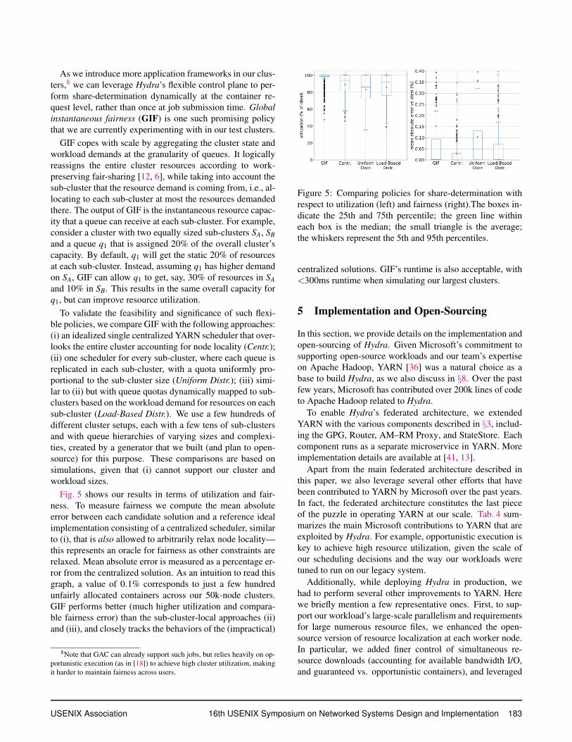
To validate the feasibility and significance of such flexi-
ble policies, we compare GIF with the following approaches:
(i) an idealized single centralized YARN scheduler that over-
looks the entire cluster accounting for node locality (Centr.);
(ii) one scheduler for every sub-cluster, where each queue is
replicated in each sub-cluster, with a quota uniformly pro-
portional to the sub-cluster size (Uniform Distr.); (iii) simi-
lar to (ii) but with queue quotas dynamically mapped to sub-
clusters based on the workload demand for resources on each
sub-cluster (Load-Based Distr.). We use a few hundreds of
different cluster setups, each with a few tens of sub-clusters
and with queue hierarchies of varying sizes and complexi-
ties, created by a generator that we built (and plan to open-
source) for this purpose. These comparisons are based on
simulations, given that (i) cannot support our cluster and
workload sizes.
Fig. 5 shows our results in terms of utilization and fair-
ness. To measure fairness we compute the mean absolute
error between each candidate solution and a reference ideal
implementation consisting of a centralized scheduler, similar
to (i), that is also allowed to arbitrarily relax node locality—
this represents an oracle for fairness as other constraints are
relaxed. Mean absolute error is measured as a percentage er-
ror from the centralized solution. As an intuition to read this
graph, a value of 0.1% corresponds to just a few hundred
unfairly allocated containers across our 50k-node clusters.
GIF performs better (much higher utilization and compara-
ble fairness error) than the sub-cluster-local approaches (ii)
and (iii), and closely tracks the behaviors of the (impractical)
8Note that GAC can already support such jobs, but relies heavily on op-
portunistic execution (as in [18]) to achieve high cluster utilization, making
it harder to maintain fairness across users.
Figure 5: Comparing policies for share-determination with
respect to utilization (left) and fairness (right).The boxes in-
dicate the 25th and 75th percentile; the green line within
each box is the median; the small triangle is the average;
the whiskers represent the 5th and 95th percentiles.
centralized solutions. GIF’s runtime is also acceptable, with
<300ms runtime when simulating our largest clusters.
5 Implementation and Open-Sourcing
In this section, we provide details on the implementation and
open-sourcing of Hydra. Given Microsoft’s commitment to
supporting open-source workloads and our team’s expertise
on Apache Hadoop, YARN [36] was a natural choice as a
base to build Hydra, as we also discuss in §8. Over the past
few years, Microsoft has contributed over 200k lines of code
to Apache Hadoop related to Hydra.
To enable Hydra’s federated architecture, we extended
YARN with the various components described in §3, includ-
ing the GPG, Router, AM–RM Proxy, and StateStore. Each
component runs as a separate microservice in YARN. More
implementation details are available at [41, 13].
Apart from the main federated architecture described in
this paper, we also leverage several other efforts that have
been contributed to YARN by Microsoft over the past years.
In fact, the federated architecture constitutes the last piece
of the puzzle in operating YARN at our scale. Tab. 4 sum-
marizes the main Microsoft contributions to YARN that are
exploited by Hydra. For example, opportunistic execution is
key to achieve high resource utilization, given the scale of
our scheduling decisions and the way our workloads were
tuned to run on our legacy system.
Additionally, while deploying Hydra in production, we
had to perform several other improvements to YARN. Here
we briefly mention a few representative ones. First, to sup-
port our workload’s large-scale parallelism and requirements
for large numerous resource files, we enhanced the open-
source version of resource localization at each worker node.
In particular, we added finer control of simultaneous re-
source downloads (accounting for available bandwidth I/O,
and guaranteed vs. opportunistic containers), and leveraged
USENIX Association 16th USENIX Symposium on Networked Systems Design and Implementation 183
Feature JIRAs Hadoop version Publications
Federated architecture [41] 2.9 this paper
Scheduling policies [13] ongoing this paper
Opportunistic execution [22, 39] 2.9 [18, 27]
Reservation planning [29, 28] 2.9 [9, 17]
Placement constraints [24] 3.1 [11]
Container preemption [25] 2.1 [36]
Table 4: Key Microsoft contributions to YARN, which are
relevant to Hydra. For each feature, we provide the main
JIRA numbers (where the open-source effort can be tracked),
the version of Apache Hadoop that first included it, and re-
lated publications.
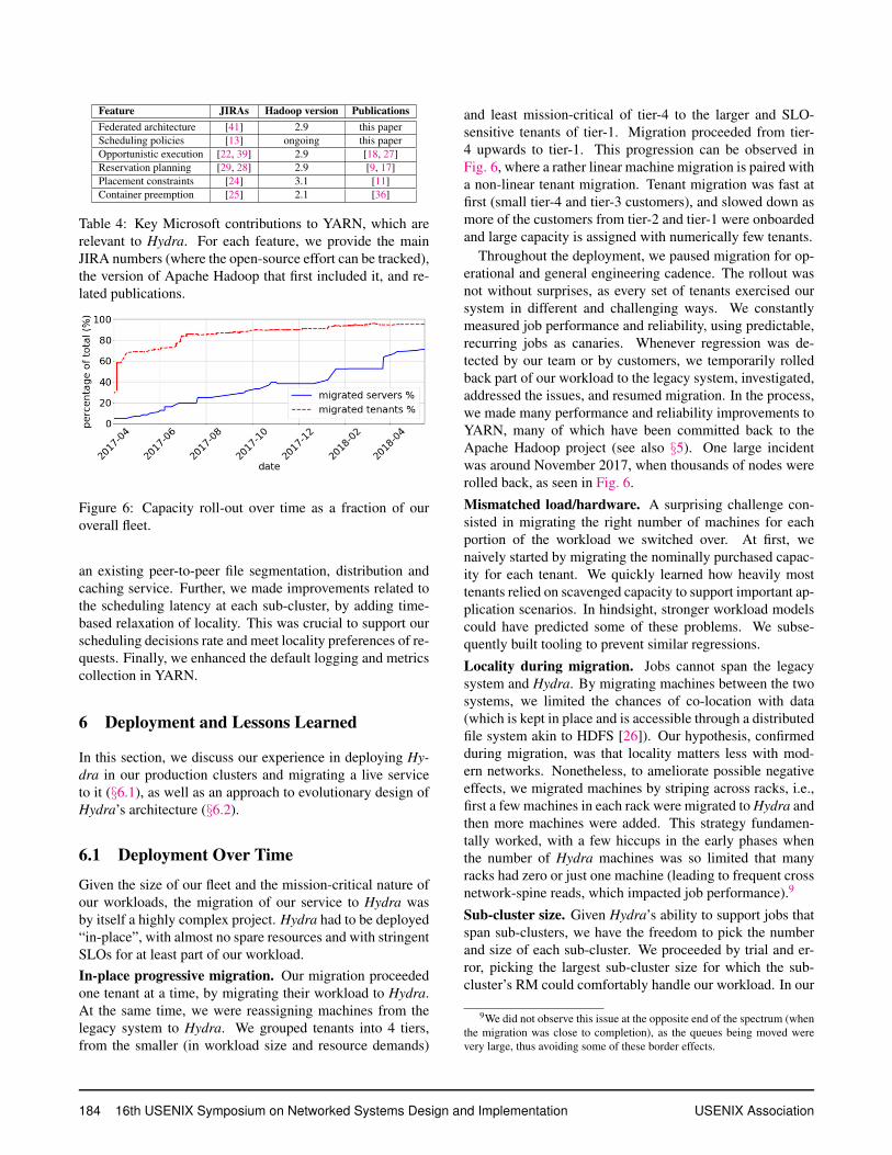
Figure 6: Capacity roll-out over time as a fraction of our
overall fleet.
an existing peer-to-peer file segmentation, distribution and
caching service. Further, we made improvements related to
the scheduling latency at each sub-cluster, by adding time-
based relaxation of locality. This was crucial to support our
scheduling decisions rate and meet locality preferences of re-
quests. Finally, we enhanced the default logging and metrics
collection in YARN.
6 Deployment and Lessons Learned
In this section, we discuss our experience in deploying Hy-
dra in our production clusters and migrating a live service
to it (§6.1), as well as an approach to evolutionary design of
Hydra’s architecture (§6.2).
6.1 Deployment Over Time
Given the size of our fleet and the mission-critical nature of
our workloads, the migration of our service to Hydra was
by itself a highly complex project. Hydra had to be deployed
“in-place”, with almost no spare resources and with stringent
SLOs for at least part of our workload.
In-place progressive migration. Our migration proceeded
one tenant at a time, by migrating their workload to Hydra.
At the same time, we were reassigning machines from the
legacy system to Hydra. We grouped tenants into 4 tiers,
from the smaller (in workload size and resource demands)
and least mission-critical of tier-4 to the larger and SLO-
sensitive tenants of tier-1. Migration proceeded from tier-
4 upwards to tier-1. This progression can be observed in
Fig. 6, where a rather linear machine migration is paired with
a non-linear tenant migration. Tenant migration was fast at
first (small tier-4 and tier-3 customers), and slowed down as
more of the customers from tier-2 and tier-1 were onboarded
and large capacity is assigned with numerically few tenants.
Throughout the deployment, we paused migration for op-
erational and general engineering cadence. The rollout was
not without surprises, as every set of tenants exercised our
system in different and challenging ways. We constantly
measured job performance and reliability, using predictable,
recurring jobs as canaries. Whenever regression was de-
tected by our team or by customers, we temporarily rolled
back part of our workload to the legacy system, investigated,
addressed the issues, and resumed migration. In the process,
we made many performance and reliability improvements to
YARN, many of which have been committed back to the
Apache Hadoop project (see also §5). One large incident
was around November 2017, when thousands of nodes were
rolled back, as seen in Fig. 6.
Mismatched load/hardware. A surprising challenge con-
sisted in migrating the right number of machines for each
portion of the workload we switched over. At first, we
naively started by migrating the nominally purchased capac-
ity for each tenant. We quickly learned how heavily most
tenants relied on scavenged capacity to support important ap-
plication scenarios. In hindsight, stronger workload models
could have predicted some of these problems. We subse-
quently built tooling to prevent similar regressions.
Locality during migration. Jobs cannot span the legacy
system and Hydra. By migrating machines between the two
systems, we limited the chances of co-location with data
(which is kept in place and is accessible through a distributed
file system akin to HDFS [26]). Our hypothesis, confirmed
during migration, was that locality matters less with mod-
ern networks. Nonetheless, to ameliorate possible negative
effects, we migrated machines by striping across racks, i.e.,
first a few machines in each rack were migrated to Hydra and
then more machines were added. This strategy fundamen-
tally worked, with a few hiccups in the early phases when
the number of Hydra machines was so limited that many
racks had zero or just one machine (leading to frequent cross
network-spine reads, which impacted job performance).9
Sub-cluster size. Given Hydra’s ability to support jobs that
span sub-clusters, we have the freedom to pick the number
and size of each sub-cluster. We proceeded by trial and er-
ror, picking the largest sub-cluster size for which the sub-
cluster’s RM could comfortably handle our workload. In our
9We did not observe this issue at the opposite end of the spectrum (when
the migration was close to completion), as the queues being moved were
very large, thus avoiding some of these border effects.
184 16th USENIX Symposium on Networked Systems Design and Implementation USENIX Association
deployments, the deciding factor for this limit is the schedul-
ing rate and not the number of nodes. In its current imple-
mentation, the RM cannot support more than 1k schedul-
ing decisions per second (SDPS), while recent, extensive ef-
forts to improve RM’s scalability have raised this bar to 5k
SDPS under ideal conditions [40]. This is still about an or-
der magnitude lower than our target SDPS, and has not yet
been tested in production at scale. Hydra’s ability to tweak
each sub-cluster’s size allowed us to experiment with differ-
ent sizes while impacting only part of our capacity (e.g., set-
ting one sub-cluster to be larger/smaller than others). In our
current deployments, we operate clusters with 15–20 sub-
clusters, each with 2k–3k nodes. We are also working to-
wards merging some of these clusters, creating even larger
and cross-DC Hydra deployments. So far, we have not en-
countered any obvious upper bound to Hydra’s scalability.
6.2 Evolutionary Design
Through careful analysis and design, we were reasonably
successful at designing the “static” aspects of the system,
such as core architectural choices and basic mechanisms.
Conversely, predicting all system “dynamics” and the effects
of multiple interacting algorithmic policies was exceedingly
hard. Moreover, we knew that the workload and the hard-
ware environment Hydra had to target in its lifetime were
certainly going to change over time.
Therefore, we invested in faithful simulation infrastruc-
ture [30], which proved invaluable (similar to what was re-
ported by the Borg team [37]), and focused on designing
mechanisms that allowed us to test and deploy policies very
quickly. In particular, Hydra can propagate new policy be-
haviors across many thousands of nodes within seconds (by-
passing the slower mechanisms provided by the underlying
deployment infrastructure [16]). This agility allowed us to
experiment with policies and respond to outages quickly.
This flexibility enabled us to leverage Hydra to support sub-
cluster level A/B testing and specialized tuning for alterna-
tive environments. Hydra is, in fact, now being considered
for smaller/specialized clusters, where federation is not used
to achieve scale, but rather operational flexibility. The abil-
ity to test policies on parts of our clusters and quickly revert
them, made it possible to experiment with advanced policies,
as the ones discussed in §4. This enables faster innovation,
which we believe is a generally under-appreciated aspect of
real-world systems. Similar considerations were discussed
by the TensorFlow team [4].
7 Production Validation
In this section we provide data from our production environ-
ments running Hydra, comparing (whenever possible) with
our legacy system [7]. As already discussed (see §1, §2), our
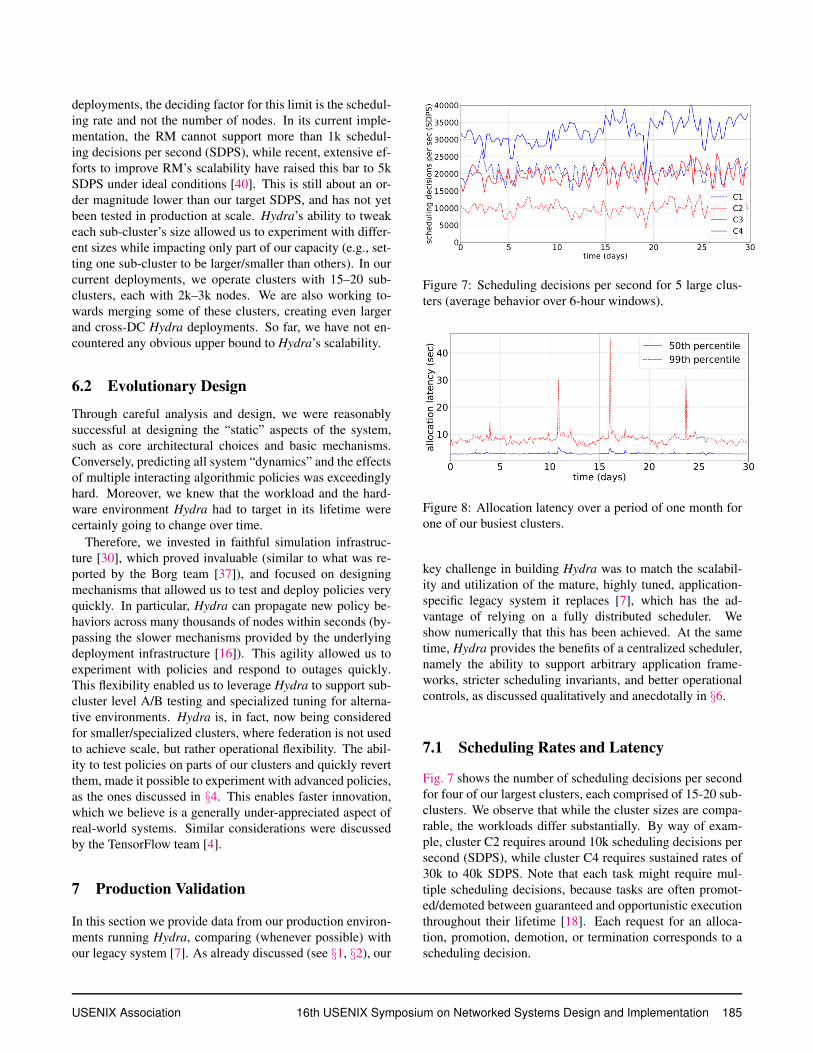
Figure 7: Scheduling decisions per second for 5 large clus-
ters (average behavior over 6-hour windows).
Figure 8: Allocation latency over a period of one month for
one of our busiest clusters.
key challenge in building Hydra was to match the scalabil-
ity and utilization of the mature, highly tuned, application-
specific legacy system it replaces [7], which has the ad-
vantage of relying on a fully distributed scheduler. We
show numerically that this has been achieved. At the same
time, Hydra provides the benefits of a centralized scheduler,
namely the ability to support arbitrary application frame-
works, stricter scheduling invariants, and better operational
controls, as discussed qualitatively and anecdotally in §6.
7.1 Scheduling Rates and Latency
Fig. 7 shows the number of scheduling decisions per second
for four of our largest clusters, each comprised of 15-20 sub-
clusters. We observe that while the cluster sizes are compa-
rable, the workloads differ substantially. By way of exam-
ple, cluster C2 requires around 10k scheduling decisions per
second (SDPS), while cluster C4 requires sustained rates of
30k to 40k SDPS. Note that each task might require mul-
tiple scheduling decisions, because tasks are often promot-
ed/demoted between guaranteed and opportunistic execution
throughout their lifetime [18]. Each request for an alloca-
tion, promotion, demotion, or termination corresponds to a
scheduling decision.
USENIX Association 16th USENIX Symposium on Networked Systems Design and Implementation 185
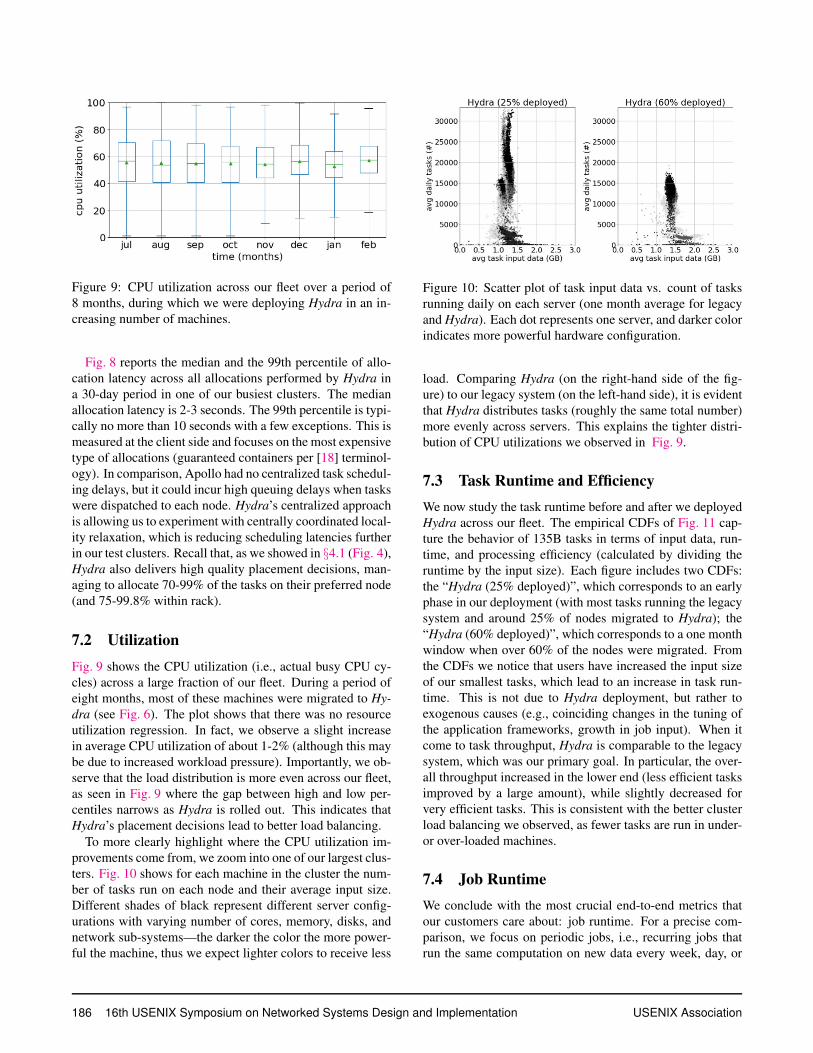
Figure 9: CPU utilization across our fleet over a period of
8 months, during which we were deploying Hydra in an in-
creasing number of machines.
Fig. 8 reports the median and the 99th percentile of allo-
cation latency across all allocations performed by Hydra in
a 30-day period in one of our busiest clusters. The median
allocation latency is 2-3 seconds. The 99th percentile is typi-
cally no more than 10 seconds with a few exceptions. This is
measured at the client side and focuses on the most expensive
type of allocations (guaranteed containers per [18] terminol-
ogy). In comparison, Apollo had no centralized task schedul-
ing delays, but it could incur high queuing delays when tasks
were dispatched to each node. Hydra’s centralized approach
is allowing us to experiment with centrally coordinated local-
ity relaxation, which is reducing scheduling latencies further
in our test clusters. Recall that, as we showed in §4.1 (Fig. 4),
Hydra also delivers high quality placement decisions, man-
aging to allocate 70-99% of the tasks on their preferred node
(and 75-99.8% within rack).
7.2 Utilization
Fig. 9 shows the CPU utilization (i.e., actual busy CPU cy-
cles) across a large fraction of our fleet. During a period of
eight months, most of these machines were migrated to Hy-
dra (see Fig. 6). The plot shows that there was no resource
utilization regression. In fact, we observe a slight increase
in average CPU utilization of about 1-2% (although this may
be due to increased workload pressure). Importantly, we ob-
serve that the load distribution is more even across our fleet,
as seen in Fig. 9 where the gap between high and low per-
centiles narrows as Hydra is rolled out. This indicates that
Hydra’s placement decisions lead to better load balancing.
To more clearly highlight where the CPU utilization im-
provements come from, we zoom into one of our largest clus-
ters. Fig. 10 shows for each machine in the cluster the num-
ber of tasks run on each node and their average input size.
Different shades of black represent different server config-
urations with varying number of cores, memory, disks, and
network sub-systems—the darker the color the more power-
ful the machine, thus we expect lighter colors to receive less
Figure 10: Scatter plot of task input data vs. count of tasks
running daily on each server (one month average for legacy
and Hydra). Each dot represents one server, and darker color
indicates more powerful hardware configuration.
load. Comparing Hydra (on the right-hand side of the fig-
ure) to our legacy system (on the left-hand side), it is evident
that Hydra distributes tasks (roughly the same total number)
more evenly across servers. This explains the tighter distri-
bution of CPU utilizations we observed in Fig. 9.
7.3 Task Runtime and Efficiency
We now study the task runtime before and after we deployed
Hydra across our fleet. The empirical CDFs of Fig. 11 cap-
ture the behavior of 135B tasks in terms of input data, run-
time, and processing efficiency (calculated by dividing the
runtime by the input size). Each figure includes two CDFs:
the “Hydra (25% deployed)”, which corresponds to an early
phase in our deployment (with most tasks running the legacy
system and around 25% of nodes migrated to Hydra); the
“Hydra (60% deployed)”, which corresponds to a one month
window when over 60% of the nodes were migrated. From
the CDFs we notice that users have increased the input size
of our smallest tasks, which lead to an increase in task run-
time. This is not due to Hydra deployment, but rather to
exogenous causes (e.g., coinciding changes in the tuning of
the application frameworks, growth in job input). When it
come to task throughput, Hydra is comparable to the legacy
system, which was our primary goal. In particular, the over-
all throughput increased in the lower end (less efficient tasks
improved by a large amount), while slightly decreased for
very efficient tasks. This is consistent with the better cluster
load balancing we observed, as fewer tasks are run in under-
or over-loaded machines.
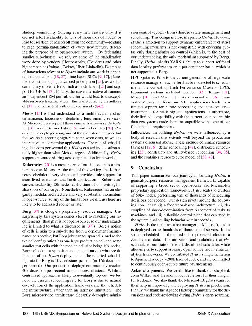
7.4 Job Runtime
We conclude with the most crucial end-to-end metrics that
our customers care about: job runtime. For a precise com-
parison, we focus on periodic jobs, i.e., recurring jobs that
run the same computation on new data every week, day, or
186 16th USENIX Symposium on Networked Systems Design and Implementation USENIX Association
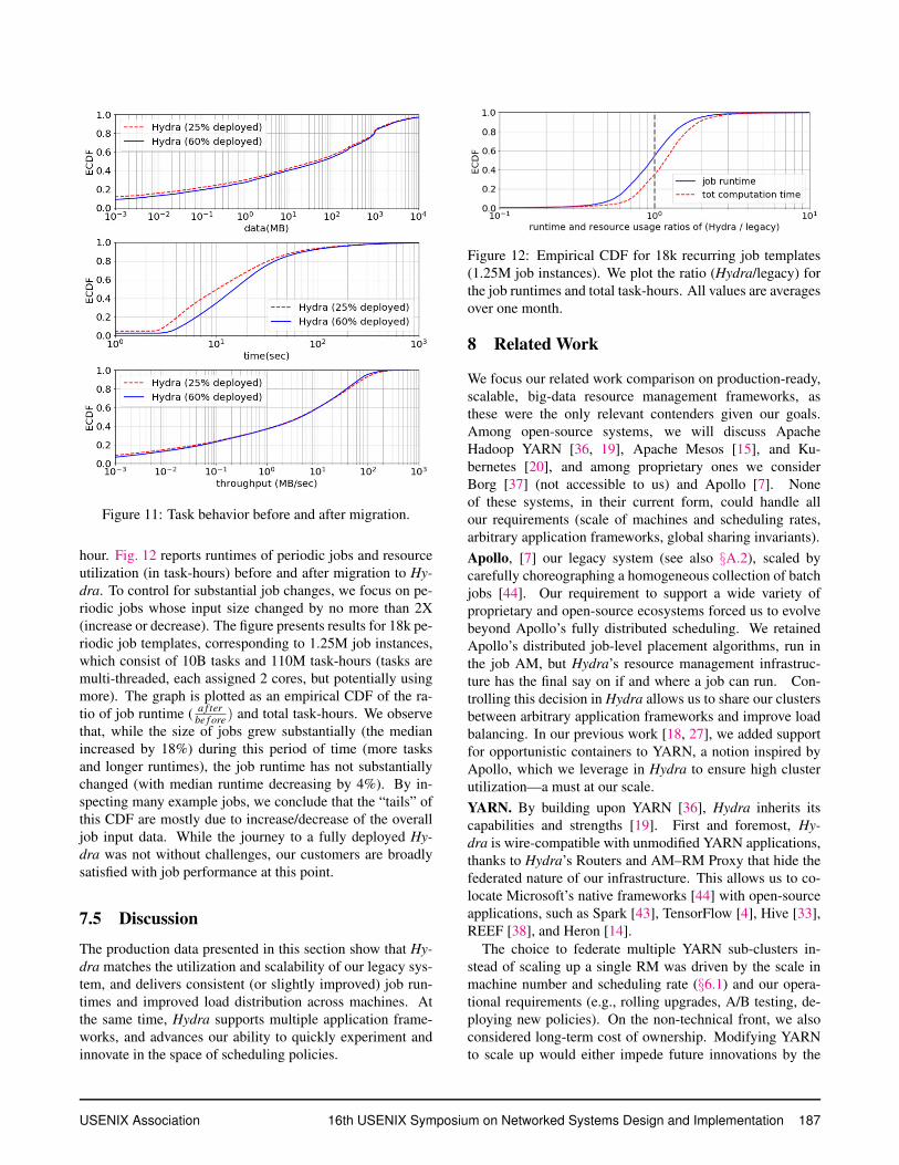
Figure 11: Task behavior before and after migration.
hour. Fig. 12 reports runtimes of periodic jobs and resource
utilization (in task-hours) before and after migration to Hy-
dra. To control for substantial job changes, we focus on pe-
riodic jobs whose input size changed by no more than 2X
(increase or decrease). The figure presents results for 18k pe-
riodic job templates, corresponding to 1.25M job instances,
which consist of 10B tasks and 110M task-hours (tasks are
multi-threaded, each assigned 2 cores, but potentially using
more). The graph is plotted as an empirical CDF of the ra-
tio of job runtime (a f ter
be f ore) and total task-hours. We observe
that, while the size of jobs grew substantially (the median
increased by 18%) during this period of time (more tasks
and longer runtimes), the job runtime has not substantially
changed (with median runtime decreasing by 4%). By in-
specting many example jobs, we conclude that the “tails” of
this CDF are mostly due to increase/decrease of the overall
job input data. While the journey to a fully deployed Hy-
dra was not without challenges, our customers are broadly
satisfied with job performance at this point.
7.5 Discussion
The production data presented in this section show that Hy-
dra matches the utilization and scalability of our legacy sys-
tem, and delivers consistent (or slightly improved) job run-
times and improved load distribution across machines. At
the same time, Hydra supports multiple application frame-
works, and advances our ability to quickly experiment and
innovate in the space of scheduling policies.
Figure 12: Empirical CDF for 18k recurring job templates
(1.25M job instances). We plot the ratio (Hydra/legacy) for
the job runtimes and total task-hours. All values are averages
over one month.
8 Related Work
We focus our related work comparison on production-ready,
scalable, big-data resource management frameworks, as
these were the only relevant contenders given our goals.
Among open-source systems, we will discuss Apache
Hadoop YARN [36, 19], Apache Mesos [15], and Ku-
bernetes [20], and among proprietary ones we consider
Borg [37] (not accessible to us) and Apollo [7]. None
of these systems, in their current form, could handle all
our requirements (scale of machines and scheduling rates,
arbitrary application frameworks, global sharing invariants).
Apollo, [7] our legacy system (see also §A.2), scaled by
carefully choreographing a homogeneous collection of batch
jobs [44]. Our requirement to support a wide variety of
proprietary and open-source ecosystems forced us to evolve
beyond Apollo’s fully distributed scheduling. We retained
Apollo’s distributed job-level placement algorithms, run in
the job AM, but Hydra’s resource management infrastruc-
ture has the final say on if and where a job can run. Con-
trolling this decision in Hydra allows us to share our clusters
between arbitrary application frameworks and improve load
balancing. In our previous work [18, 27], we added support
for opportunistic containers to YARN, a notion inspired by
Apollo, which we leverage in Hydra to ensure high cluster
utilization—a must at our scale.
YARN. By building upon YARN [36], Hydra inherits its
capabilities and strengths [19]. First and foremost, Hy-
dra is wire-compatible with unmodified YARN applications,
thanks to Hydra’s Routers and AM–RM Proxy that hide the
federated nature of our infrastructure. This allows us to co-
locate Microsoft’s native frameworks [44] with open-source
applications, such as Spark [43], TensorFlow [4], Hive [33],
REEF [38], and Heron [14].
The choice to federate multiple YARN sub-clusters in-
stead of scaling up a single RM was driven by the scale in
machine number and scheduling rate (§6.1) and our opera-
tional requirements (e.g., rolling upgrades, A/B testing, de-
ploying new policies). On the non-technical front, we also
considered long-term cost of ownership. Modifying YARN
to scale up would either impede future innovations by the
USENIX Association 16th USENIX Symposium on Networked Systems Design and Implementation 187
Hadoop community (forcing every new feature only if it
did not affect scalability to tens of thousands of nodes) or
lead to isolation of Microsoft from the community—leading
to high porting/stabilization of every new feature, defeat-
ing the purpose of an open-source system. By federating
smaller sub-clusters, we rely on some of the stabilization
work done by vendors (Hortonworks, Cloudera) and other
big companies (Yahoo!, Twitter, Uber, LinkedIn). Examples
of innovations relevant to Hydra include our work in oppor-
tunistic containers [18, 27], time-based SLOs [9, 17], place-
ment constraints [11], advanced preemption [25], as well as
community-driven efforts, such as node labels [21] and sup-
port for GPUs [19]. Finally, the naive alternative of running
an independent RM per sub-cluster would lead to unaccept-
able resource fragmentation—this was studied by the authors
of [37] and consistent with our experiments (§4.2).
Mesos [15] is best understood as a highly scalable clus-
ter manager, focusing on deploying long running services.
At Microsoft, we support three similar frameworks, AutoPi-
lot [16], Azure Service Fabric [5], and Kubernetes [20]. Hy-
dra can be deployed using any of these cluster managers, but
focuses on supporting high-rate batch workloads, as well as
interactive and streaming applications. The rate of schedul-
ing decisions per second that Hydra can achieve is substan-
tially higher than what Mesos targets. Additionally, Hydra
supports resource sharing across application frameworks.
Kubernetes [20] is a more recent effort that occupies a sim-
ilar space as Mesos. At the time of this writing, the Kuber-
netes scheduler is very simple and provides little support for
short-lived containers and batch applications. Kubernetes’
current scalability (5k nodes at the time of this writing) is
also short of our target. Nonetheless, Kubernetes has an ele-
gantly modular architecture and very substantial momentum
in open-source, so any of the limitations we discuss here are
likely to be addressed sooner or later.
Borg [37] is Google’s proprietary resource manager. Un-
surprisingly, this system comes closest to matching our re-
quirements (though it is not open-source, so our understand-
ing is limited to what is discussed in [37]). Borg’s notion
of cells is akin to a sub-cluster from a deployment/mainte-
nance perspective, but Borg jobs cannot span cells, and so the
typical configuration has one large production cell and some
smaller test cells with the median cell size being 10k nodes.
Borg cells do not span data centers, contrary to what we do
in some of our Hydra deployments. The reported schedul-
ing rate for Borg is 10k decisions per min (or 166 decisions
per second). Our production deployment routinely reaches
40k decisions per second in our busiest clusters. While a
centralized approach is likely to eventually top out, we be-
lieve the current scheduling rate for Borg is due to natural
co-evolution of the application framework and the schedul-
ing infrastructure, rather than an intrinsic limitation. The
Borg microservice architecture elegantly decouples admis-
sion control (quotas) from (sharded) state management and
scheduling. This design is close in spirit to Hydra. However,
Hydra’s ambition to support dynamic enforcement of strict
scheduling invariants is not compatible with checking quo-
tas only during admission control (which is, to the best of
our understanding, the only mechanism supported by Borg).
Finally, Hydra inherits YARN’s ability to support soft/hard
data locality preferences on a per-container basis, which is
not supported in Borg.
HPC systems. Prior to the current generation of large-scale
resource managers, much effort has been devoted to schedul-
ing in the context of High Performance Clusters (HPC).
Prominent systems included Condor [32], Torque [31],
Moab [10], and Maui [1]. As discussed in [36], these
systems’ original focus on MPI applications leads to a
limited support for elastic scheduling and data-locality—
instrumental for batch big data applications. Furthermore,
their limited compatibility with the current open-source big
data ecosystems made them incompatible with some of our
fundamental requirements.
Influences. In building Hydra, we were influenced by a
body of research that extends well beyond the production
systems discussed above. These include dominant resource
fairness [12, 6], delay scheduling [42], distributed schedul-
ing [23], constraint- and utility-based scheduling [34, 35],
and the container reuse/executor model of [38, 43].
9 Conclusion
This paper summarizes our journey in building Hydra, a
general-purpose resource management framework, capable
of supporting a broad set of open-source and Microsoft’s
proprietary application frameworks. Hydra scales to clusters
of 50k+ nodes, performing tens of thousands of scheduling
decisions per second. Our design pivots around the follow-
ing core ideas: (i) a federation-based architecture, (ii) de-
coupling of share-determination from placement of tasks to
machines, and (iii) a flexible control-plane that can modify
the system’s scheduling behavior within seconds.
Hydra is the main resource manager at Microsoft, and it
is deployed across hundreds of thousands of servers. It has
so far scheduled a trillion tasks that processed close to a
Zettabyte of data. The utilization and scalability that Hy-
dra matches our state-of-the-art, distributed scheduler, while
allowing us to support arbitrary open-source and internal an-
alytics frameworks. We contributed Hydra’s implementation
to Apache Hadoop (∼200k lines of code), and are committed
to continuously open-source future advancements.
Acknowledgments. We would like to thank our shepherd,
John Wilkes, and the anonymous reviewers for their insight-
ful feedback. We also thank the Microsoft BigData team for
their help in improving and deploying Hydra in production.
Finally, we thank the Apache Hadoop community for the dis-
cussions and code-reviewing during Hydra’s open-sourcing.
188 16th USENIX Symposium on Networked Systems Design and Implementation USENIX Association
References
[1] Maui Scheduler Open Cluster Software. http://mauischeduler.
sourceforge.net/, 2005.
[2] Hadoop: Writing yarn applications. https://hadoop.apache.
org/docs/stable/hadoop-yarn/hadoop-yarn-site/
WritingYarnApplications.html, 2012.
[3] Work-preserving NodeManager restart. https://issues.apache.
org/jira/browse/YARN-1336, 2014.
[4] ABADI, M., BARHAM, P., CHEN, J., CHEN, Z., DAVIS, A., DEAN,
J., DEVIN, M., GHEMAWAT, S., IRVING, G., ISARD, M., KUD-
LUR, M., LEVENBERG, J., MONGA, R., MOORE, S., MURRAY,
D. G., STEINER, B., TUCKER, P. A., VASUDEVAN, V., WARDEN,
P., WICKE, M., YU, Y., AND ZHENG, X. TensorFlow: A System for
Large-Scale Machine Learning. In OSDI (2016).
[5] BAI, H. Programming Microsoft Azure Service Fabric. Microsoft
Press, 2018.
[6] BHATTACHARYA, ARKA, C., DAVID CULLER, F., ERIC FRIED-
MAN, G., ALI, S., SCOTT, A. S., AND STOICA, I. Hierarchical
Scheduling for Diverse Datacenter Workloads. In SOCC (2013).
[7] BOUTIN, E., EKANAYAKE, J., LIN, W., SHI, B., ZHOU, J., QIAN,
Z., WU, M., AND ZHOU, L. Apollo: Scalable and Coordinated
Scheduling for Cloud-Scale Computing. In OSDI (2014).
[8] CANO, I., WEIMER, M., MAHAJAN, D., CURINO, C., FUMAROLA,
G. M., AND KRISHNAMURTHY, A. Towards geo-distributed machine
learning. IEEE Data Eng. Bull. (2017).
[9] CURINO, C., DIFALLAH, D. E., DOUGLAS, C., KRISHNAN, S.,
RAMAKRISHNAN, R., AND RAO, S. Reservation-based Scheduling:
If You’re Late Don’t Blame Us! In SOCC (2014).
[10] EMENEKER, W., JACKSON, D., BUTIKOFER, J., AND STANZIONE,
D. Dynamic virtual clustering with Xen and Moab. In ISPA (2006).
[11] GAREFALAKIS, P., KARANASOS, K., PIETZUCH, P. R., SURESH,
A., AND RAO, S. Medea: scheduling of long running applications in
shared production clusters. In EuroSys (2018).
[12] GHODSI, A., ZAHARIA, M., HINDMAN, B., KONWINSKI, A.,
SHENKER, S., AND STOICA, I. Dominant Resource Fairness: Fair
Allocation of Multiple Resource Types. In NSDI (2011).
[13] Federation v2: Global optimizations. https://issues.apache.
org/jira/browse/YARN-7402, 2018.
[14] Heron. http://apache.github.io/incubator-heron, 2018.
[15] HINDMAN, B., KONWINSKI, A., ZAHARIA, M., GHODSI, A.,
JOSEPH, A. D., KATZ, R., SHENKER, S., AND STOICA, I. Mesos:
A Platform for Fine-Grained Resource Sharing in the Data Center. In
NSDI (2011).
[16] ISARD, M. Autopilot: automatic data center management. ACM
SIGOPS Operating Systems Review (2007).
[17] JYOTHI, S. A., CURINO, C., MENACHE, I., NARAYANAMURTHY,
S. M., TUMANOV, A., YANIV, J., MAVLYUTOV, R., GOIRI, I., KR-
ISHNAN, S., KULKARNI, J., AND RAO, S. Morpheus: Towards Au-
tomated SLOs for Enterprise Clusters. In OSDI (2016).
[18] KARANASOS, K., RAO, S., CURINO, C., DOUGLAS, C., CHALI-
PARAMBIL, K., FUMAROLA, G. M., HEDDAYA, S., RAMAKRISH-
NAN, R., AND SAKALANAGA, S. Mercury: Hybrid Centralized and
Distributed Scheduling in Large Shared Clusters. In USENIX ATC
(2015).
[19] KARANASOS, K., SURESH, A., AND DOUGLAS, C. Advancements
in YARN Resource Manager. Encyclopedia of Big Data Technologies
(February 2018).
[20] Kubernetes. http://kubernetes.io, 2018.
[21] Node labels: Allow for (admin) labels on nodes and resource-requests.
https://issues.apache.org/jira/browse/YARN-796, 2014.
[22] Scheduling of opportunistic containers through YARN RM. https:
//issues.apache.org/jira/browse/YARN-5220, 2017.
[23] OUSTERHOUT, K., WENDELL, P., ZAHARIA, M., AND STOICA, I.
Sparrow: Distributed, low latency scheduling. In SOSP (2013).
[24] Rich placement constraints in YARN. https://issues.apache.
org/jira/browse/YARN-6592, 2018.
[25] Preemption: Scheduler feedback to AM to release containers. https:
//issues.apache.org/jira/browse/YARN-45, 2013.
[26] RAMAKRISHNAN, R., SRIDHARAN, B., DOUCEUR, J. R., KAS-
TURI, P., KRISHNAMACHARI-SAMPATH, B., KRISHNAMOORTHY,
K., LI, P., MANU, M., MICHAYLOV, S., RAMOS, R., SHARMAN,
N., XU, Z., BARAKAT, Y., DOUGLAS, C., DRAVES, R., NAIDU,
S. S., SHASTRY, S., SIKARIA, A., SUN, S., AND VENKATESAN, R.
Azure Data Lake Store: A Hyperscale Distributed File Service for Big
Data Analytics. In SIGMOD (2017).
[27] RASLEY, J., KARANASOS, K., KANDULA, S., FONSECA, R., VO-
JNOVIC, M., AND RAO, S. Efficient Queue Management for Cluster
Scheduling. In EuroSys (2016).
[28] Support for recurring reservations in the YARN ReservationSystem.
https://issues.apache.org/jira/browse/YARN-5326, 2018.
[29] Yarn admission control/planner: enhancing the resource allocation
model with time. https://issues.apache.org/jira/browse/
YARN-1051, 2018.
[30] Scheduler Load Simulator for Apache Hadoop YARN. https://
issues.apache.org/jira/browse/YARN-5065, 2017.
[31] STAPLES, G. TORQUE resource manager. In IEEE SC (2006).
[32] TANNENBAUM, T., WRIGHT, D., MILLER, K., AND LIVNY, M.
Condor: A Distributed Job Scheduler. In Beowulf Cluster Comput-
ing with Linux (2001).
[33] THUSOO, A., SARMA, J. S., JAIN, N., SHAO, Z., CHAKKA, P.,
ZHANG, N., ANTHONY, S., LIU, H., AND MURTHY, R. Hive - A
Petabyte Scale Data Warehouse Using Hadoop. In ICDE (2010).
[34] TUMANOV, A., CIPAR, J., GANGER, G. R., AND KOZUCH, M. A.
Alsched: Algebraic Scheduling of Mixed Workloads in Heteroge-
neous Clouds. In SOCC (2012).
[35] TUMANOV, A., ZHU, T., PARK, J. W., KOZUCH, M. A., HARCHOL-
BALTER, M., AND GANGER, G. R. TetriSched: global rescheduling
with adaptive plan-ahead in dynamic heterogeneous clusters. In Eu-
roSys (2016).
[36] VAVILAPALLI, V. K., MURTHY, A. C., DOUGLAS, C., AGARWAL,
S., KONAR, M., EVANS, R., GRAVES, T., LOWE, J., SHAH, H.,
SETH, S., ET AL. Apache Hadoop YARN: Yet Another Resource
Negotiator. In SOCC (2013).
[37] VERMA, A., PEDROSA, L., KORUPOLU, M., OPPENHEIMER, D.,
TUNE, E., AND WILKES, J. Large-scale cluster management at
Google with Borg. In EuroSys (2015).
[38] WEIMER, M., CHEN, Y., CHUN, B.-G., CONDIE, T., CURINO,
C., DOUGLAS, C., LEE, Y., MAJESTRO, T., MALKHI, D., MATU-
SEVYCH, S., MYERS, B., NARAYANAMURTHY, S., RAMAKRISH-
NAN, R., RAO, S., SEARS, R., SEZGIN, B., AND WANG, J. REEF:
Retainable evaluator execution framework. In SIGMOD (2015).
[39] Extend YARN to support distributed scheduling. https://issues.
apache.org/jira/browse/YARN-2877, 2017.
[40] Move YARN scheduler towards global scheduler. https://issues.
apache.org/jira/browse/YARN-5139, 2018.
[41] Enable YARN RM scale out via federation using multiple RM’s.
https://issues.apache.org/jira/browse/YARN-2915, 2017.
[42] ZAHARIA, M., BORTHAKUR, D., SEN SARMA, J., ELMELEEGY,
K., SHENKER, S., AND STOICA, I. Delay Scheduling: A Simple
Technique for Achieving Locality and Fairness in Cluster Scheduling.
In EuroSys (2010).
USENIX Association 16th USENIX Symposium on Networked Systems Design and Implementation 189
Job Manager
...3
4
Heartbeats
Resource Manager
1
2
Job Manager
Job Manager
Node Manager
Run TasksQueued Tasks
Node Manager
Run TasksQueued Tasks
Application Master
Figure 13: (Non-federated) YARN architecture.
[43] ZAHARIA, M., CHOWDHURY, M., FRANKLIN, M. J., SHENKER,
S., AND STOICA, I. Spark: Cluster Computing with Working Sets. In
HotCloud (2010).
[44] ZHOU, J., BRUNO, N., WU, M.-C., LARSON, P.-A., CHAIKEN,
R., AND SHAKIB, D. SCOPE: parallel databases meet MapReduce.
VLDB J. 21, 5 (2012), 611–636.
A Overview of YARN and Apollo
As discussed in Sections 2.3 and 3, we built Hydra by ex-
tending and re-architecting Apache Hadoop YARN [36] to
substitute our legacy system Apollo from which we also
drew ideas [7]. For convenience to the reader, below we pro-
vide a brief overview of YARN and Apollo, given their close
ties to Hydra.10
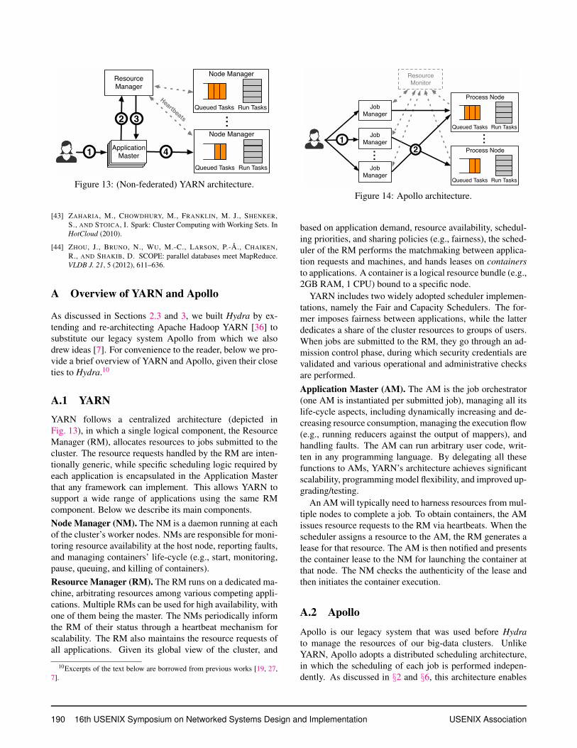
A.1 YARN
YARN follows a centralized architecture (depicted in
Fig. 13), in which a single logical component, the Resource
Manager (RM), allocates resources to jobs submitted to the
cluster. The resource requests handled by the RM are inten-
tionally generic, while specific scheduling logic required by
each application is encapsulated in the Application Master
that any framework can implement. This allows YARN to
support a wide range of applications using the same RM
component. Below we describe its main components.
Node Manager (NM). The NM is a daemon running at each
of the cluster’s worker nodes. NMs are responsible for moni-
toring resource availability at the host node, reporting faults,
and managing containers’ life-cycle (e.g., start, monitoring,
pause, queuing, and killing of containers).
Resource Manager (RM). The RM runs on a dedicated ma-
chine, arbitrating resources among various competing appli-
cations. Multiple RMs can be used for high availability, with
one of them being the master. The NMs periodically inform
the RM of their status through a heartbeat mechanism for
scalability. The RM also maintains the resource requests of
all applications. Given its global view of the cluster, and
10Excerpts of the text below are borrowed from previous works [19, 27,
7].
...
Resource Monitor
1
... 2
Process Node
Run TasksQueued Tasks
Process Node
Run TasksQueued Tasks
Job Manager
Job Manager
Job Manager
Figure 14: Apollo architecture.
based on application demand, resource availability, schedul-
ing priorities, and sharing policies (e.g., fairness), the sched-
uler of the RM performs the matchmaking between applica-
tion requests and machines, and hands leases on containers
to applications. A container is a logical resource bundle (e.g.,
2GB RAM, 1 CPU) bound to a specific node.
YARN includes two widely adopted scheduler implemen-
tations, namely the Fair and Capacity Schedulers. The for-
mer imposes fairness between applications, while the latter
dedicates a share of the cluster resources to groups of users.
When jobs are submitted to the RM, they go through an ad-
mission control phase, during which security credentials are
validated and various operational and administrative checks
are performed.
Application Master (AM). The AM is the job orchestrator
(one AM is instantiated per submitted job), managing all its
life-cycle aspects, including dynamically increasing and de-
creasing resource consumption, managing the execution flow
(e.g., running reducers against the output of mappers), and
handling faults. The AM can run arbitrary user code, writ-
ten in any programming language. By delegating all these
functions to AMs, YARN’s architecture achieves significant
scalability, programming model flexibility, and improved up-
grading/testing.
An AM will typically need to harness resources from mul-
tiple nodes to complete a job. To obtain containers, the AM
issues resource requests to the RM via heartbeats. When the
scheduler assigns a resource to the AM, the RM generates a
lease for that resource. The AM is then notified and presents
the container lease to the NM for launching the container at
that node. The NM checks the authenticity of the lease and
then initiates the container execution.
A.2 Apollo
Apollo is our legacy system that was used before Hydra
to manage the resources of our big-data clusters. Unlike
YARN, Apollo adopts a distributed scheduling architecture,
in which the scheduling of each job is performed indepen-
dently. As discussed in §2 and §6, this architecture enables
190 16th USENIX Symposium on Networked Systems Design and Implementation USENIX Association
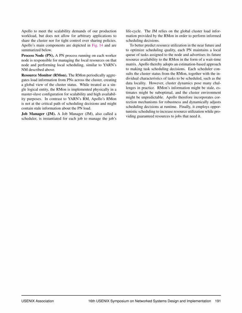
Apollo to meet the scalability demands of our production
workload, but does not allow for arbitrary applications to
share the cluster nor for tight control over sharing policies.
Apollo’s main components are depicted in Fig. 14 and are
summarized below.
Process Node (PN). A PN process running on each worker
node is responsible for managing the local resources on that
node and performing local scheduling, similar to YARN’s
NM described above.
Resource Monitor (RMon). The RMon periodically aggre-
gates load information from PNs across the cluster, creating
a global view of the cluster status. While treated as a sin-
gle logical entity, the RMon is implemented physically in a
master-slave configuration for scalability and high availabil-
ity purposes. In contrast to YARN’s RM, Apollo’s RMon
is not at the critical path of scheduling decisions and might
contain stale information about the PN load.
Job Manager (JM). A Job Manager (JM), also called a
scheduler, is instantiated for each job to manage the job’s
life-cycle. The JM relies on the global cluster load infor-
mation provided by the RMon in order to perform informed
scheduling decisions.
To better predict resource utilization in the near future and
to optimize scheduling quality, each PN maintains a local
queue of tasks assigned to the node and advertises its future
resource availability to the RMon in the form of a wait-time
matrix. Apollo thereby adopts an estimation-based approach
to making task scheduling decisions. Each scheduler con-
sults the cluster status from the RMon, together with the in-
dividual characteristics of tasks to be scheduled, such as the
data locality. However, cluster dynamics pose many chal-
lenges in practice. RMon’s information might be stale, es-
timates might be suboptimal, and the cluster environment
might be unpredictable. Apollo therefore incorporates cor-
rection mechanisms for robustness and dynamically adjusts
scheduling decisions at runtime. Finally, it employs oppor-
tunistic scheduling to increase resource utilization while pro-
viding guaranteed resources to jobs that need it.
USENIX Association 16th USENIX Symposium on Networked Systems Design and Implementation 191

![PerfOrator: eloquent performance models for Resource ... · Kaushik Rajan, Dharmesh Kakadia, Carlo Curino, Subru Krishnan Microsoft [krajan, dkakadia, ccurino, subru]@microsoft.com](https://img.pdfslide.us/doc/110x75/5fa8320ec66ea05ebe03f8dd/perforator-eloquent-performance-models-for-resource-kaushik-rajan-dharmesh.jpg)