Embed Size (px)
Citation preview
IEEE TRANSACTIONS ON COMMUNICATIONS, VOL. 51, NO. 7, JULY 2003 1135
Hybrid Pulse Position Modulation/Ultrashort LightPulse Code-Division Multiple-Access Systems—Part
II: Time–Space Processor and Modified SchemesKwang Soon Kim, Member, IEEE, Dan M. Marom, Member, IEEE, Laurence B. Milstein, Fellow, IEEE, and
Yeshaiahu Fainman, Fellow, IEEE
Abstract—In Part I of this two-part paper, we proposed andinvestigated a hybrid pulse position modulation/ultrashort lightpulse code-division multiple-access (PPM/ULP-CDMA) systemfor ultrafast optical communication networks. In the proposedscheme, the large bandwidth of an ULP is efficiently utilized byvirtue of the very high time resolution of a time–space processor.In this paper, more detailed analysis and discussion on the receiverscheme using the time–space processor is presented; nonidealperformance of the time–space processor, including the referencepulse realization problem, as well as amplifier and detector noise,are taken into account. Discussions on physically achievableranges of the system parameters that determine the performanceof the proposed PPM/ULP-CDMA system are also made basedupon current, state of the art technology. As remedies to overcomethe physical limitations on the system parameters, two modifiedmodulation/demodulation schemes are proposed and investigatedto enhance the performance of the hybrid PPM/ULP-CDMAsystem.
Index Terms—Optical code-division multiple access (CDMA),pulse position modulation (PPM), time–space processor, ultra-short light pulse (ULP).
I. INTRODUCTION
I N [1], we proposed and investigated a hybrid pulse positionmodulation/ultrashort light pulse code-division mul-
tiple-access (PPM/ULP-CDMA) system to provide ultrafastcommunication in multiple-access optical networks. In theproposed hybrid PPM/ULP-CDMA system, a pulse positionmodulation (PPM) format with very short pulse separationwas used to utilize the given large bandwidth of an ultrashort
Paper approved by J. A. Salehi, the Editor for Optical CDMA of the IEEECommunications Society. Manuscript received May 24, 2001; revised August23, 2002. This work was supported by the National Science Foundation underGrant NSF-9813721 and under Grant NSF-0123405. The work of K. S. Kim andD. M. Marom was supported by the Korea Science and Engineering Foundation(KOSEF) and the Fannie and John Hertz Foundation, respectively.
K. S. Kim was with the Department of Electrical and Computer Engineering,University of California, San Diego, La Jolla, CA 92093 USA. He is nowwith the Mobile Telecommunication Research Laboratory, Electronics andTelecommunication Research Institute, Daejeon 305-350, Korea (e-mail:[email protected]).
D. M. Marom was with the Department of Electrical and Computer Engi-neering, University of California, San Diego, La Jolla, CA 92093 USA. He isnow with Advanced Photonics Research, Bell Laboratories, Lucent Technolo-gies, Holmdel, NJ 07733 USA (e-mail: [email protected]).
L. B. Milstein and Y. Fainman are with the Department of Electrical andComputer Engineering, University of California, San Diego, La Jolla, CA92093-0407 USA (e-mail: [email protected]; [email protected]).
Digital Object Identifier 10.1109/TCOMM.2003.814234
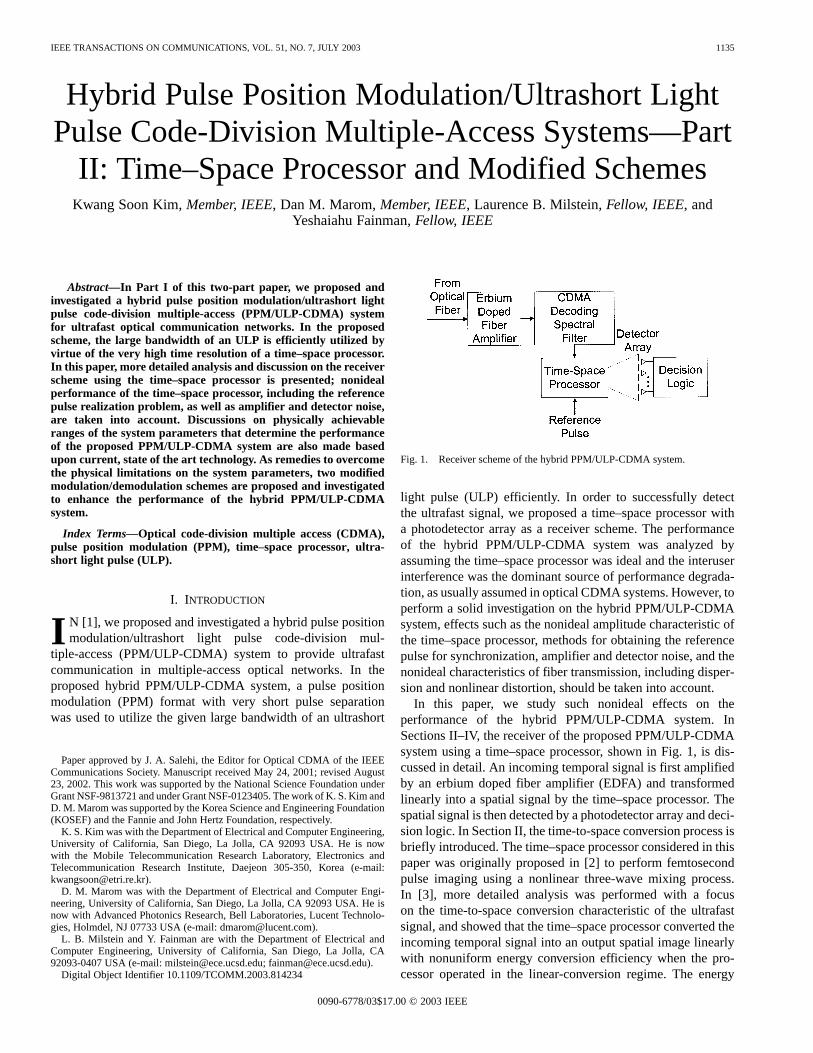
Fig. 1. Receiver scheme of the hybrid PPM/ULP-CDMA system.
light pulse (ULP) efficiently. In order to successfully detectthe ultrafast signal, we proposed a time–space processor witha photodetector array as a receiver scheme. The performanceof the hybrid PPM/ULP-CDMA system was analyzed byassuming the time–space processor was ideal and the interuserinterference was the dominant source of performance degrada-tion, as usually assumed in optical CDMA systems. However, toperform a solid investigation on the hybrid PPM/ULP-CDMAsystem, effects such as the nonideal amplitude characteristic ofthe time–space processor, methods for obtaining the referencepulse for synchronization, amplifier and detector noise, and thenonideal characteristics of fiber transmission, including disper-sion and nonlinear distortion, should be taken into account.
In this paper, we study such nonideal effects on theperformance of the hybrid PPM/ULP-CDMA system. InSections II–IV, the receiver of the proposed PPM/ULP-CDMAsystem using a time–space processor, shown in Fig. 1, is dis-cussed in detail. An incoming temporal signal is first amplifiedby an erbium doped fiber amplifier (EDFA) and transformedlinearly into a spatial signal by the time–space processor. Thespatial signal is then detected by a photodetector array and deci-sion logic. In Section II, the time-to-space conversion process isbriefly introduced. The time–space processor considered in thispaper was originally proposed in [2] to perform femtosecondpulse imaging using a nonlinear three-wave mixing process.In [3], more detailed analysis was performed with a focuson the time-to-space conversion characteristic of the ultrafastsignal, and showed that the time–space processor converted theincoming temporal signal into an output spatial image linearlywith nonuniform energy conversion efficiency when the pro-cessor operated in the linear-conversion regime. The energy
0090-6778/03$17.00 © 2003 IEEE
1136 IEEE TRANSACTIONS ON COMMUNICATIONS, VOL. 51, NO. 7, JULY 2003
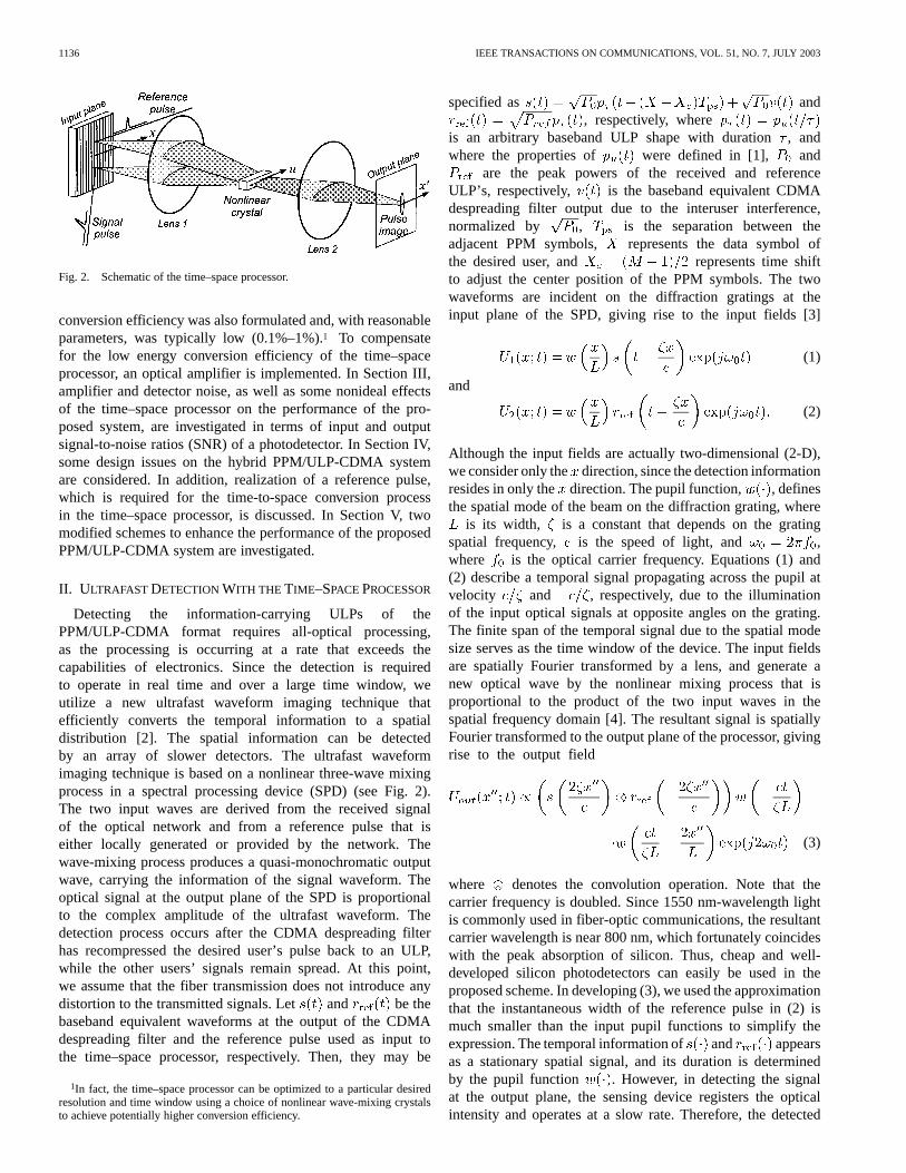
Fig. 2. Schematic of the time–space processor.
conversion efficiency was also formulated and, with reasonableparameters, was typically low (0.1%–1%).1 To compensatefor the low energy conversion efficiency of the time–spaceprocessor, an optical amplifier is implemented. In Section III,amplifier and detector noise, as well as some nonideal effectsof the time–space processor on the performance of the pro-posed system, are investigated in terms of input and outputsignal-to-noise ratios (SNR) of a photodetector. In Section IV,some design issues on the hybrid PPM/ULP-CDMA systemare considered. In addition, realization of a reference pulse,which is required for the time-to-space conversion processin the time–space processor, is discussed. In Section V, twomodified schemes to enhance the performance of the proposedPPM/ULP-CDMA system are investigated.
II. ULTRAFAST DETECTIONWITH THE TIME–SPACEPROCESSOR
Detecting the information-carrying ULPs of thePPM/ULP-CDMA format requires all-optical processing,as the processing is occurring at a rate that exceeds thecapabilities of electronics. Since the detection is requiredto operate in real time and over a large time window, weutilize a new ultrafast waveform imaging technique thatefficiently converts the temporal information to a spatialdistribution [2]. The spatial information can be detectedby an array of slower detectors. The ultrafast waveformimaging technique is based on a nonlinear three-wave mixingprocess in a spectral processing device (SPD) (see Fig. 2).The two input waves are derived from the received signalof the optical network and from a reference pulse that iseither locally generated or provided by the network. Thewave-mixing process produces a quasi-monochromatic outputwave, carrying the information of the signal waveform. Theoptical signal at the output plane of the SPD is proportionalto the complex amplitude of the ultrafast waveform. Thedetection process occurs after the CDMA despreading filterhas recompressed the desired user’s pulse back to an ULP,while the other users’ signals remain spread. At this point,we assume that the fiber transmission does not introduce anydistortion to the transmitted signals. Let and be thebaseband equivalent waveforms at the output of the CDMAdespreading filter and the reference pulse used as input tothe time–space processor, respectively. Then, they may be
1In fact, the time–space processor can be optimized to a particular desiredresolution and time window using a choice of nonlinear wave-mixing crystalsto achieve potentially higher conversion efficiency.
specified as and, respectively, where
is an arbitrary baseband ULP shape with duration, andwhere the properties of were defined in [1], and
are the peak powers of the received and referenceULP’s, respectively, is the baseband equivalent CDMAdespreading filter output due to the interuser interference,normalized by , is the separation between theadjacent PPM symbols, represents the data symbol ofthe desired user, and represents time shiftto adjust the center position of the PPM symbols. The twowaveforms are incident on the diffraction gratings at theinput plane of the SPD, giving rise to the input fields [3]
(1)
and
(2)
Although the input fields are actually two-dimensional (2-D),we consider only the direction, since the detection informationresides in only the direction. The pupil function, , definesthe spatial mode of the beam on the diffraction grating, where
is its width, is a constant that depends on the gratingspatial frequency, is the speed of light, and ,where is the optical carrier frequency. Equations (1) and(2) describe a temporal signal propagating across the pupil atvelocity and , respectively, due to the illuminationof the input optical signals at opposite angles on the grating.The finite span of the temporal signal due to the spatial modesize serves as the time window of the device. The input fieldsare spatially Fourier transformed by a lens, and generate anew optical wave by the nonlinear mixing process that isproportional to the product of the two input waves in thespatial frequency domain [4]. The resultant signal is spatiallyFourier transformed to the output plane of the processor, givingrise to the output field
(3)
where denotes the convolution operation. Note that thecarrier frequency is doubled. Since 1550 nm-wavelength lightis commonly used in fiber-optic communications, the resultantcarrier wavelength is near 800 nm, which fortunately coincideswith the peak absorption of silicon. Thus, cheap and well-developed silicon photodetectors can easily be used in theproposed scheme. In developing (3), we used the approximationthat the instantaneous width of the reference pulse in (2) ismuch smaller than the input pupil functions to simplify theexpression. The temporal information of and appearsas a stationary spatial signal, and its duration is determinedby the pupil function . However, in detecting the signalat the output plane, the sensing device registers the opticalintensity and operates at a slow rate. Therefore, the detected
KIM et al.: HYBRID PULSE POSITION MODULATION/ULTRASHORT LIGHT PULSE CODE-DIVISION MULTIPLE-ACCESS SYSTEMS—PART II 1137
signal is given by
(4)
The convolution integral of the input pupil functions limits therange of the output spatial signal. Subsequently, this limitsthe observed input temporal signal. Additional insight to theoutput detected signal is gained if we introduce a Gaussianmodel for the input beam profiles, i.e., .Using the Gaussian mode model, the integral in (4) can beevaluated, and inserting the definitions for the signal andreference waveforms yields
(5)
From (5), we see that a data pulse is detected at loca-tion , and is attenuated by
due tothe processor’s time window. It is apparent that the detectedsignal level from each possible pulse position is different.However, the attenuation is knowna priori and affects thedesired signal and interference in the same manner, and can,therefore, be taken into consideration in the decision logic(that is, normalizing by the attenuation) if detector noise isnegligible. More detailed optical analysis of the time–spaceprocessor is available in [3].
III. A MPLIFIER AND DETECTORNOISE
In Section II, the time–space processor was considered toconvert fast temporal signals into spatial images to performfast signal detection. The energy conversion efficiency of thetime–space processor is formulated in [3], and, with reasonableparameters and reference pulse energy, the energy conversionefficiency is typically low (0.1%–1%). In addition, transmittedpower must be sufficiently small to prevent nonlinear distortionduring propagation in the fiber. Thus, a large-gain opticalamplifier may be required to compensate for the energy con-version loss in the time–space processor. On the other hand,as will be shown later, a small photodetector size is desirableto maximize the signal-to-interuser interference ratio, which,in turn, reduces incident average power to a photodetector. Inthis case, detector noise may not be negligible. In this section,the effect of the amplifier and detector noise on the input andoutput SNR of a photodetector is investigated.
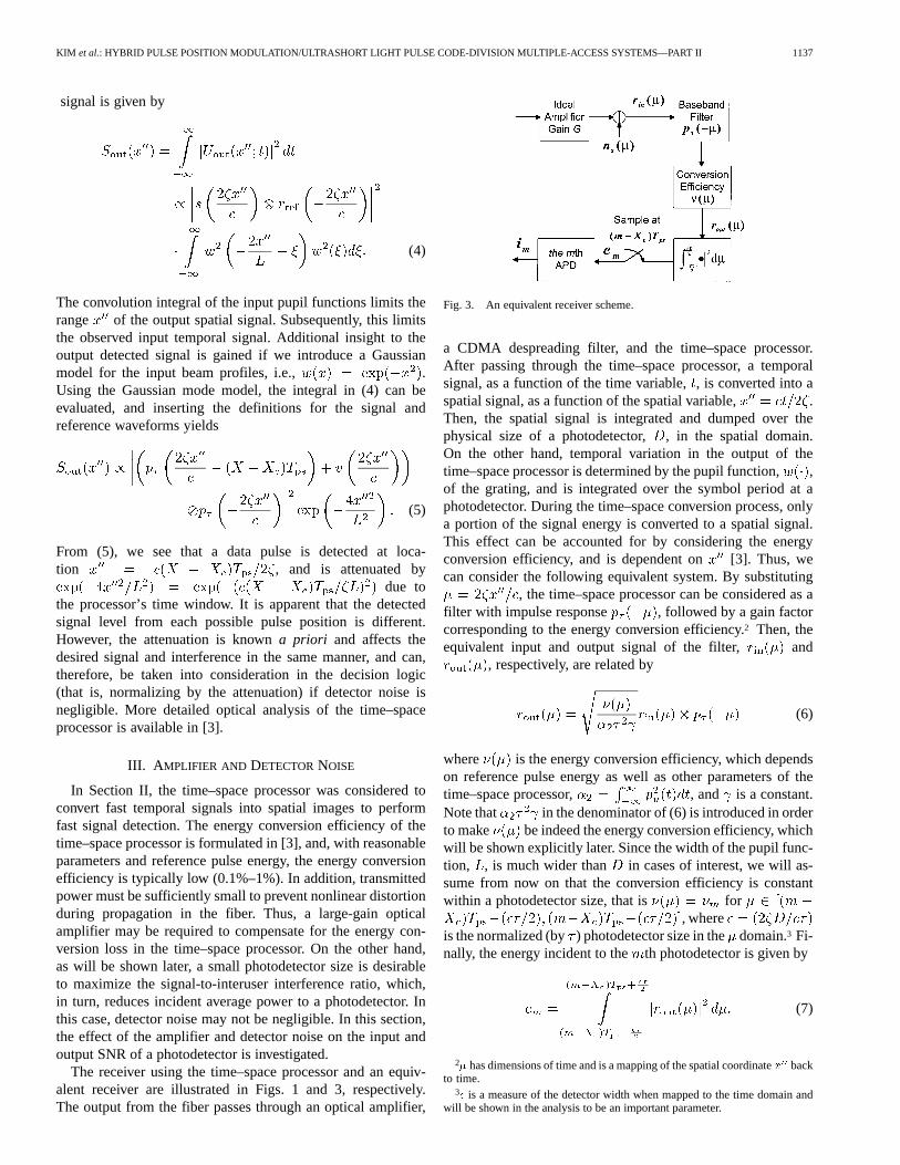
The receiver using the time–space processor and an equiv-alent receiver are illustrated in Figs. 1 and 3, respectively.The output from the fiber passes through an optical amplifier,
Fig. 3. An equivalent receiver scheme.
a CDMA despreading filter, and the time–space processor.After passing through the time–space processor, a temporalsignal, as a function of the time variable,, is converted into aspatial signal, as a function of the spatial variable, .Then, the spatial signal is integrated and dumped over thephysical size of a photodetector,, in the spatial domain.On the other hand, temporal variation in the output of thetime–space processor is determined by the pupil function,,of the grating, and is integrated over the symbol period at aphotodetector. During the time–space conversion process, onlya portion of the signal energy is converted to a spatial signal.This effect can be accounted for by considering the energyconversion efficiency, and is dependent on [3]. Thus, wecan consider the following equivalent system. By substituting
, the time–space processor can be considered as afilter with impulse response , followed by a gain factorcorresponding to the energy conversion efficiency.2 Then, theequivalent input and output signal of the filter, and
, respectively, are related by
(6)
where is the energy conversion efficiency, which dependson reference pulse energy as well as other parameters of thetime–space processor, , and is a constant.Note that in the denominator of (6) is introduced in orderto make be indeed the energy conversion efficiency, whichwill be shown explicitly later. Since the width of the pupil func-tion, , is much wider than in cases of interest, we will as-sume from now on that the conversion efficiency is constantwithin a photodetector size, that is for
, whereis the normalized (by) photodetector size in thedomain.3 Fi-nally, the energy incident to theth photodetector is given by
(7)
2� has dimensions of time and is a mapping of the spatial coordinatex backto time.
3� is a measure of the detector width when mapped to the time domain andwill be shown in the analysis to be an important parameter.
1138 IEEE TRANSACTIONS ON COMMUNICATIONS, VOL. 51, NO. 7, JULY 2003
The equivalent input signal, , can be expressed as
(8)where , is the energy of areceived ULP, is the gain of the optical amplifier, and isthe transmitted symbol. According to [1, Prop. 1 and 5, andLemma 1], the interuser interference is a zero-mean com-plex Gaussian process with correlation function
(9)
where ,represents the effective number of spec-
tral CDMA chips contained in the pulse bandwidth,is thechip bandwidth defined in [1], is the number of users, and
is the time delay of the th interferer. The approximationfollows from the assumptions that and ,which are true for most cases of interest. Here we define
(10)
as the equivalent number of interferers at theth signal loca-tion, where the term “equivalent number of interferers” comesfrom the fact that is the interference power at theth signallocation normalized by the peak interference power caused bya single interferer. The amplifier noise can be modeled as whiteGaussian noise in the range of frequency of interest [5]. Thus,
is modeled as a zero-mean complex white Gaussianprocess with two-sided spectral density[5], where is the spontaneous emission factor of theamplifier (ideally 1) and is Planck’s constant.
Consider the th photodetector output. From (6), the signalcomponent, , the interuser interference component,
, and the amplifier noise component, , ofare presented below. The signal component is given by
(11)
where is the Kronecker delta function and the last approx-imation is valid when is sufficiently larger than , as shownin [1]. Since the energy contained in is , we get
. The interuser inter-ference component
(12)
is a zero-mean complex Gaussian random process with correla-tion function
(13)
where , and the approximation comesfrom the assumption . Finally, the amplifier noise com-ponent
(14)
is a zero-mean complex Gaussian random process with correla-tion function
(15)
Let us define . Sinceand are independent, is a zero-meancomplex Gaussian process with correlation function
. Then, the meanand variance of the input energy, , to the th photodetectorare given by (see Appendix A)
(16)
and
(17)
respectively, where .Additional insight into the statistic of the photodetector input
is obtained by using the Gaussian ULP profile, that is,. Then, we get ,
, , and. Thus, we have
(18)
and
2
(19)
KIM et al.: HYBRID PULSE POSITION MODULATION/ULTRASHORT LIGHT PULSE CODE-DIVISION MULTIPLE-ACCESS SYSTEMS—PART II 1139
where , ,
(20)
, , and.
Now, define the input SNR of theth photodetector as
(21)
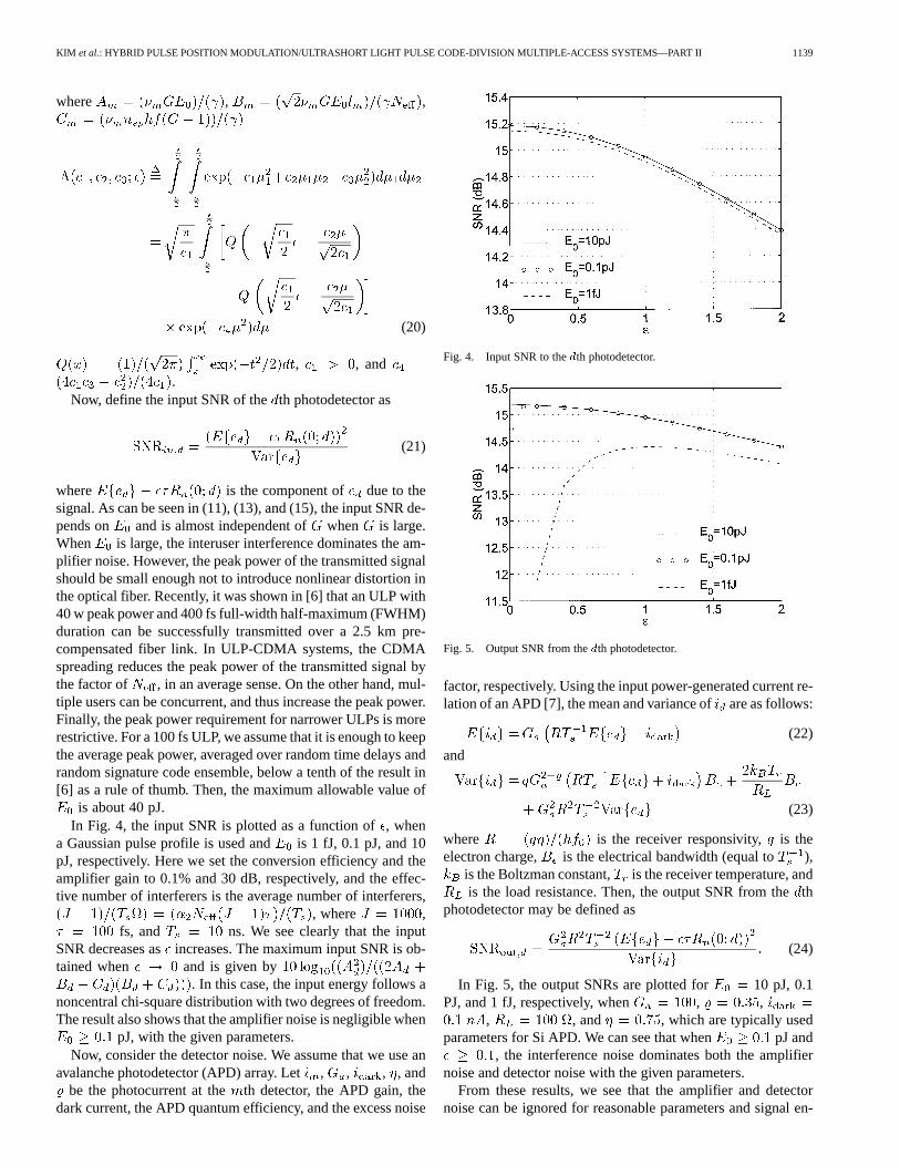
where is the component of due to thesignal. As can be seen in (11), (13), and (15), the input SNR de-pends on and is almost independent of when is large.When is large, the interuser interference dominates the am-plifier noise. However, the peak power of the transmitted signalshould be small enough not to introduce nonlinear distortion inthe optical fiber. Recently, it was shown in [6] that an ULP with40 w peak power and 400 fs full-width half-maximum (FWHM)duration can be successfully transmitted over a 2.5 km pre-compensated fiber link. In ULP-CDMA systems, the CDMAspreading reduces the peak power of the transmitted signal bythe factor of , in an average sense. On the other hand, mul-tiple users can be concurrent, and thus increase the peak power.Finally, the peak power requirement for narrower ULPs is morerestrictive. For a 100 fs ULP, we assume that it is enough to keepthe average peak power, averaged over random time delays andrandom signature code ensemble, below a tenth of the result in[6] as a rule of thumb. Then, the maximum allowable value of
is about 40 pJ.In Fig. 4, the input SNR is plotted as a function of, when
a Gaussian pulse profile is used and is 1 fJ, 0.1 pJ, and 10pJ, respectively. Here we set the conversion efficiency and theamplifier gain to 0.1% and 30 dB, respectively, and the effec-tive number of interferers is the average number of interferers,
, where ,fs, and ns. We see clearly that the input
SNR decreases asincreases. The maximum input SNR is ob-tained when and is given by
. In this case, the input energy follows anoncentral chi-square distribution with two degrees of freedom.The result also shows that the amplifier noise is negligible when
pJ, with the given parameters.Now, consider the detector noise. We assume that we use an
avalanche photodetector (APD) array. Let, , , , andbe the photocurrent at the th detector, the APD gain, the
dark current, the APD quantum efficiency, and the excess noise
Fig. 4. Input SNR to thedth photodetector.
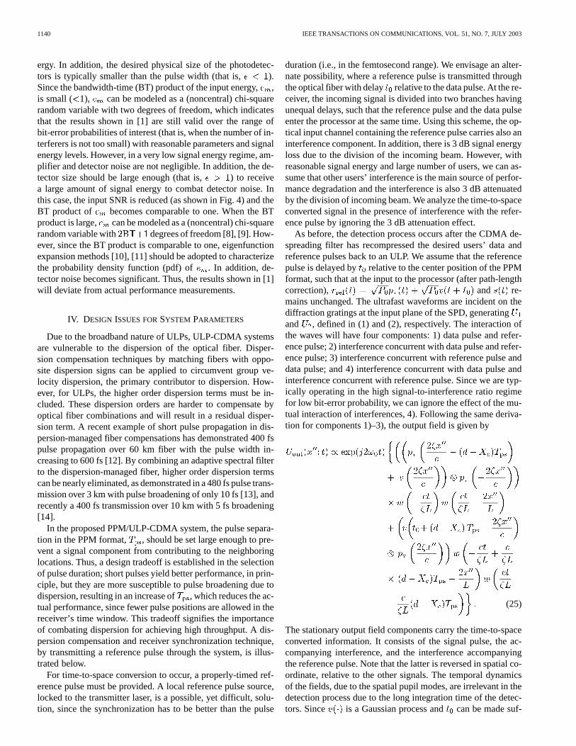
Fig. 5. Output SNR from thedth photodetector.
factor, respectively. Using the input power-generated current re-lation of an APD [7], the mean and variance ofare as follows:
(22)
and
(23)
where is the receiver responsivity, is theelectron charge, is the electrical bandwidth (equal to ),
is the Boltzman constant, is the receiver temperature, andis the load resistance. Then, the output SNR from theth
photodetector may be defined as
(24)
In Fig. 5, the output SNRs are plotted for 10 pJ, 0.1PJ, and 1 fJ, respectively, when , ,
, , and , which are typically usedparameters for Si APD. We can see that when pJ and
, the interference noise dominates both the amplifiernoise and detector noise with the given parameters.
From these results, we see that the amplifier and detectornoise can be ignored for reasonable parameters and signal en-
1140 IEEE TRANSACTIONS ON COMMUNICATIONS, VOL. 51, NO. 7, JULY 2003
ergy. In addition, the desired physical size of the photodetec-tors is typically smaller than the pulse width (that is, ).Since the bandwidth-time (BT) product of the input energy,,is small ( 1), can be modeled as a (noncentral) chi-squarerandom variable with two degrees of freedom, which indicatesthat the results shown in [1] are still valid over the range ofbit-error probabilities of interest (that is, when the number of in-terferers is not too small) with reasonable parameters and signalenergy levels. However, in a very low signal energy regime, am-plifier and detector noise are not negligible. In addition, the de-tector size should be large enough (that is, ) to receivea large amount of signal energy to combat detector noise. Inthis case, the input SNR is reduced (as shown in Fig. 4) and theBT product of becomes comparable to one. When the BTproduct is large, can be modeled as a (noncentral) chi-squarerandom variable with degrees of freedom [8], [9]. How-ever, since the BT product is comparable to one, eigenfunctionexpansion methods [10], [11] should be adopted to characterizethe probability density function (pdf) of . In addition, de-tector noise becomes significant. Thus, the results shown in [1]will deviate from actual performance measurements.
IV. DESIGN ISSUES FORSYSTEM PARAMETERS
Due to the broadband nature of ULPs, ULP-CDMA systemsare vulnerable to the dispersion of the optical fiber. Disper-sion compensation techniques by matching fibers with oppo-site dispersion signs can be applied to circumvent group ve-locity dispersion, the primary contributor to dispersion. How-ever, for ULPs, the higher order dispersion terms must be in-cluded. These dispersion orders are harder to compensate byoptical fiber combinations and will result in a residual disper-sion term. A recent example of short pulse propagation in dis-persion-managed fiber compensations has demonstrated 400 fspulse propagation over 60 km fiber with the pulse width in-creasing to 600 fs [12]. By combining an adaptive spectral filterto the dispersion-managed fiber, higher order dispersion termscan be nearly eliminated, as demonstrated in a 480 fs pulse trans-mission over 3 km with pulse broadening of only 10 fs [13], andrecently a 400 fs transmission over 10 km with 5 fs broadening[14].
In the proposed PPM/ULP-CDMA system, the pulse separa-tion in the PPM format, , should be set large enough to pre-vent a signal component from contributing to the neighboringlocations. Thus, a design tradeoff is established in the selectionof pulse duration; short pulses yield better performance, in prin-ciple, but they are more susceptible to pulse broadening due todispersion, resulting in an increase of , which reduces the ac-tual performance, since fewer pulse positions are allowed in thereceiver’s time window. This tradeoff signifies the importanceof combating dispersion for achieving high throughput. A dis-persion compensation and receiver synchronization technique,by transmitting a reference pulse through the system, is illus-trated below.
For time-to-space conversion to occur, a properly-timed ref-erence pulse must be provided. A local reference pulse source,locked to the transmitter laser, is a possible, yet difficult, solu-tion, since the synchronization has to be better than the pulse
duration (i.e., in the femtosecond range). We envisage an alter-nate possibility, where a reference pulse is transmitted throughthe optical fiber with delay relative to the data pulse. At the re-ceiver, the incoming signal is divided into two branches havingunequal delays, such that the reference pulse and the data pulseenter the processor at the same time. Using this scheme, the op-tical input channel containing the reference pulse carries also aninterference component. In addition, there is 3 dB signal energyloss due to the division of the incoming beam. However, withreasonable signal energy and large number of users, we can as-sume that other users’ interference is the main source of perfor-mance degradation and the interference is also 3 dB attenuatedby the division of incoming beam. We analyze the time-to-spaceconverted signal in the presence of interference with the refer-ence pulse by ignoring the 3 dB attenuation effect.
As before, the detection process occurs after the CDMA de-spreading filter has recompressed the desired users’ data andreference pulses back to an ULP. We assume that the referencepulse is delayed by relative to the center position of the PPMformat, such that at the input to the processor (after path-lengthcorrection), and re-mains unchanged. The ultrafast waveforms are incident on thediffraction gratings at the input plane of the SPD, generatingand , defined in (1) and (2), respectively. The interaction ofthe waves will have four components: 1) data pulse and refer-ence pulse; 2) interference concurrent with data pulse and refer-ence pulse; 3) interference concurrent with reference pulse anddata pulse; and 4) interference concurrent with data pulse andinterference concurrent with reference pulse. Since we are typ-ically operating in the high signal-to-interference ratio regimefor low bit-error probability, we can ignore the effect of the mu-tual interaction of interferences, 4). Following the same deriva-tion for components 1)–3), the output field is given by
(25)
The stationary output field components carry the time-to-spaceconverted information. It consists of the signal pulse, the ac-companying interference, and the interference accompanyingthe reference pulse. Note that the latter is reversed in spatial co-ordinate, relative to the other signals. The temporal dynamicsof the fields, due to the spatial pupil modes, are irrelevant in thedetection process due to the long integration time of the detec-tors. Since is a Gaussian process andcan be made suf-
KIM et al.: HYBRID PULSE POSITION MODULATION/ULTRASHORT LIGHT PULSE CODE-DIVISION MULTIPLE-ACCESS SYSTEMS—PART II 1141
ficiently large (e.g., several times of ) such that there is nocorrelation between the interference components, the sum of thetwo interference components is Gaussian, and its variance is thesum of that of each interference component, resulting in worseperformance, while eliminating the synchronization problem.Roughly speaking, the aggregate throughput is one-fourth ofthat expected by assuming a perfect reference pulse, since boththe number of interference pulses and the probability that aninterference pulse is concurrent with the desired one are dou-bled. To reduce the performance degradation, we can transmitthe signal and reference pulses with two orthogonal polarizationstates via a polarization preserving fiber. In this case, only theinterfering probability is doubled, and the performance degrada-tion factor is roughly a factor of two. Considering the intensitynoise, the situation could be worse. The intensity noise is on thesignal pulse as well as on the reference pulse. In addition, theintensity noise on the signal pulse could be correlated or un-correlated to that on the reference pulse, depending on how oneobtains the reference pulse. Interferers’ pulses also carry inten-sity noise. Although an exact analysis including intensity noiseis very complex and is beyond the scope of this paper, we canassume that a typical pulse-to-pulse energy variation is about1%. Thus, although it reduces the actual aggregate throughput,it would not degrade the performance seriously.
An additional advantage of using a pulse that has traveledthrough the optical fiber for the reference pulse is that the pulsecarries information about the fiber channel. The dispersion thatwill affect the data pulse also affects the reference pulse. Whenthe time–space processor is used in a communication systemwhere both the reference pulse and the signal pulse traverse thesame optical channel, all the odd-order dispersion terms are au-tomatically cancelled [15]. On the other hand, the even-orderterms are doubled in magnitude. Since the second-order disper-sion is the main source of signal distortion in uncompensatedfiber propagation, this could have a detrimental effect. However,the time–space processor can compensate for second-order dis-persion by displacing the output plane of the processor. Since thesecond-order dispersion is quadratic in the temporal frequencydomain, the converted spatial information contains quadraticphase. By free-space propagation, the spatial quadratic phase iscompensated, resulting in a signal that is distorted by the fourthand higher even orders. These orders are very weak and do notcontribute significantly to the dispersion.
In [1], it was shown that the performance of the proposedsystem depends largely on three parameters: the ULP duration
; the chip bandwidth ; and the number of possible signal po-sitions . In addition, the pulse separation, , should be se-lected to ensure signal orthogonality. In the remaining portionof this section, practical ranges of the parameters are briefly dis-cussed.
First, consider the minimum pulse separation time,, thatensures that the detected waveforms are sufficiently orthogonal.Here, we assume that the fiber dispersion effect is eliminatedby applying a good dispersion compensation technique. Sincesome pulse shapes, e.g., Gaussian, are not limited in the time do-main, we wish to establish the required distance between pulsessuch that the received signal in adjacent channels is sufficientlysmall. By using a Gaussian pulse profile, we can calculate the
signal component energy at the desired and adjacent locationsfrom (7) and (11). When , we see that assures thefractional energy spilling to a neighboring detector is less than1%. Typically, should be less than one in the moderate-to-highsignal energy regimes, as shown in Section III. In this case, thefractional energy is typically reduced further.
The advent of erbium-doped, fiber-based ultrashort pulselasers provide an ideal source for ULP communications, asthe oscillation frequency of these lasers coincides with thedesired communication band (center wavelength 1550 nm), andthe robust fiber laser can be easily and efficiently connectedto the optical network. Such lasers, based on additive-pulsemode locking, operating with fs, at 40 MHz repetition
ns), 2.25 nJ energy per pulse, and at wavelength1550 nm, have been demonstrated in [16]. Lasers with higherrepetition rates of 10 GHz ns) have also beendemonstrated with excellent jitter characteristics in [17].
The time window of the receiver is required to span the du-ration of the all possible symbols, . Using the time-to-space mapping, the duration corresponds to a spatial width of
. We seek the width of the spatial mode of the beam,, to cover this time window. Assuming that the detected values
can be as low as 10% at the window extremes, relative to thoseat the center of the window, and , then the relation-ship is established. Theoretically, we canincrease to accommodate any . However, increasing de-creases the efficiency of the time–space processor, as well asintroducing a packaging problem as the system size increases.A reasonable system may accommodate a time window on theorder of 5–50 ps, allowing up to the hundreds.
Finally, consider the spectral chip bandwidth,. The limitingfactor on the possible spectral chip bandwidth that can be em-ployed is the spectral resolution of the CDMA encoding spectralfilter. The spectral resolution can be improved by increasing thebeam size. However, a larger beam would require larger gratingsand lenses, resulting in a bulky system that is more prone to sta-bility problems. A recently demonstrated guided-wave opticalimplementation, based on arrayed waveguide grating, achievedan impressive resolution of 10 GHz in a small, robust package[18]. Thus, time-spread waveforms will emerge with typical du-rations on the order of 100 ps. This excellent performance is at-tributed to the array of 340 waveguide delay lines.
V. TWO MODIFIED SCHEMES
As discussed in [1], we can improve the performance of thehybrid PPM/ULP-CDMA system by reducing, increasing ,and/or increasing . In Section IV, however, it was shownthat there are some practical limitations on the system parame-ters. In this section, two modified schemes are proposed to over-come such difficulties and enhance the performance of the hy-brid PPM/ULP-CDMA system.
A. Multiple-Bit Transmission Scheme
The performance of the PPM/ULP-CDMA system dependslargely on . As mentioned in Section IV, however, it is dif-ficult to increase beyond a certain degree. Thus, only a
1142 IEEE TRANSACTIONS ON COMMUNICATIONS, VOL. 51, NO. 7, JULY 2003
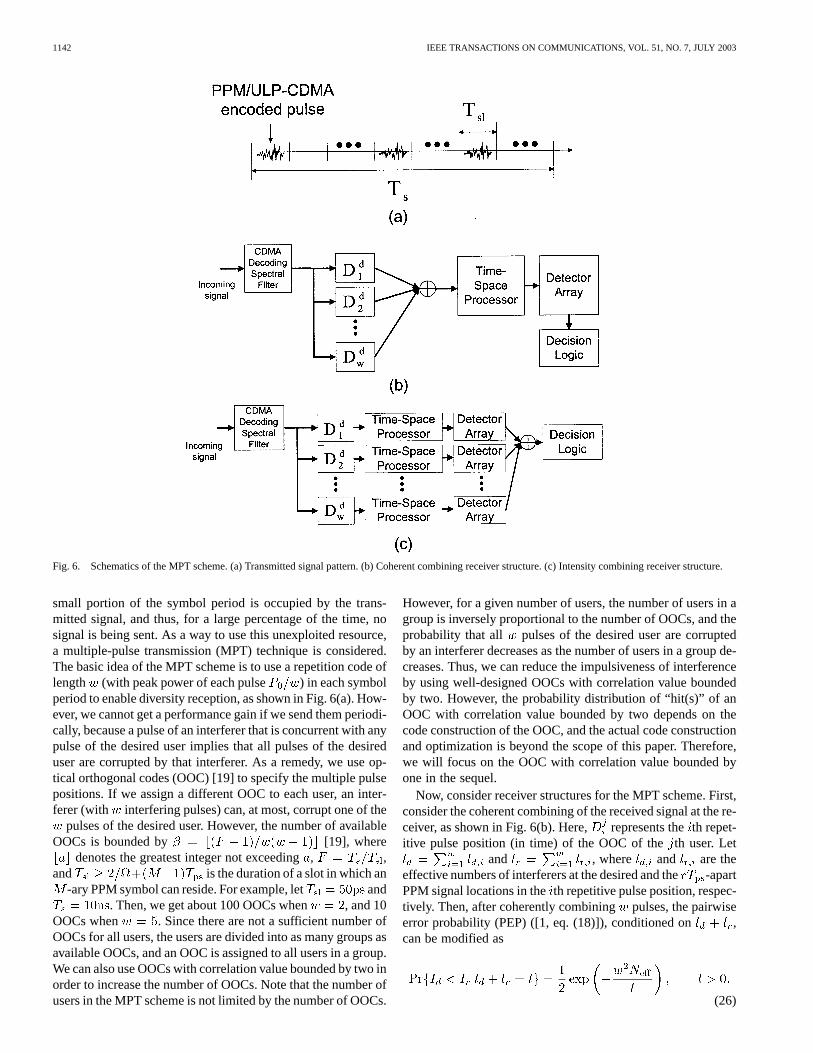
Fig. 6. Schematics of the MPT scheme. (a) Transmitted signal pattern. (b) Coherent combining receiver structure. (c) Intensity combining receiver structure.
small portion of the symbol period is occupied by the trans-mitted signal, and thus, for a large percentage of the time, nosignal is being sent. As a way to use this unexploited resource,a multiple-pulse transmission (MPT) technique is considered.The basic idea of the MPT scheme is to use a repetition code oflength (with peak power of each pulse ) in each symbolperiod to enable diversity reception, as shown in Fig. 6(a). How-ever, we cannot get a performance gain if we send them periodi-cally, because a pulse of an interferer that is concurrent with anypulse of the desired user implies that all pulses of the desireduser are corrupted by that interferer. As a remedy, we use op-tical orthogonal codes (OOC) [19] to specify the multiple pulsepositions. If we assign a different OOC to each user, an inter-ferer (with interfering pulses) can, at most, corrupt one of the
pulses of the desired user. However, the number of availableOOCs is bounded by [19], where
denotes the greatest integer not exceeding, ,and is the duration of a slot in which an
-ary PPM symbol can reside. For example, let and. Then, we get about 100 OOCs when , and 10
OOCs when . Since there are not a sufficient number ofOOCs for all users, the users are divided into as many groups asavailable OOCs, and an OOC is assigned to all users in a group.We can also use OOCs with correlation value bounded by two inorder to increase the number of OOCs. Note that the number ofusers in the MPT scheme is not limited by the number of OOCs.
However, for a given number of users, the number of users in agroup is inversely proportional to the number of OOCs, and theprobability that all pulses of the desired user are corruptedby an interferer decreases as the number of users in a group de-creases. Thus, we can reduce the impulsiveness of interferenceby using well-designed OOCs with correlation value boundedby two. However, the probability distribution of “hit(s)” of anOOC with correlation value bounded by two depends on thecode construction of the OOC, and the actual code constructionand optimization is beyond the scope of this paper. Therefore,we will focus on the OOC with correlation value bounded byone in the sequel.
Now, consider receiver structures for the MPT scheme. First,consider the coherent combining of the received signal at the re-ceiver, as shown in Fig. 6(b). Here, represents theth repet-itive pulse position (in time) of the OOC of theth user. Let
and , where and are theeffective numbers of interferers at the desired and the-apartPPM signal locations in theth repetitive pulse position, respec-tively. Then, after coherently combining pulses, the pairwiseerror probability (PEP) ([1, eq. (18)]), conditioned on ,can be modified as
(26)
KIM et al.: HYBRID PULSE POSITION MODULATION/ULTRASHORT LIGHT PULSE CODE-DIVISION MULTIPLE-ACCESS SYSTEMS—PART II 1143
The term in the numerator of the exponent of (26) arises asfollows. From [1, eq. (16)–(18)], the variance of the interferenceis given by . Also, the signal power is dueto the coherent combining. Thus, the signal-to-interference ratiobecomes . On the other hand, the probability
should be modified also. Since the crosscorre-lations of the OOCs are bounded by one, at most, one encodedpulse of an interferer can be concurrent with the desired user’spulses. Since each user transmitsencoded pulses, and the timewindow of interest of the desired user increases totimes thatin the conventional hybrid PPM/ULP-CDMA system (that is,
pulses of the desired user are combined), the probability thatone encoded pulse of an interferer is within the time window ofinterest of the desired user is times that in the conventionalscheme (here, the effect of insufficient OOCs is ignored for sim-plicity). Then, [1, eq. (20)] can be modified as
(27)
Note that the time interval is used instead offor simplicity. This can be justified from the
facts that is typically much smaller than and that, as seenin [1, Fig. 5], the amount of interference caused by an interfereris relatively small when the time delay of the interferer iswithin or . Since
and , (26) and (27) are equivalentto those of the conventional hybrid PPM/ULP-CDMA systemwith the spectral chip bandwidth , which means theeffective number of chips increased by a factor of. Thus,from [1, eqs. (21)–(25)], it is seen that the performance ofthe MPT/coherent combining is equivalent to that of theconventional hybrid PPM/ULP-CDMA system with effectivenumber of chips increased by a factor of , which impliesthe performance of the hybrid PPM/ULP-CDMA system isimproved by the MPT/coherent combining scheme. However,the implementation of the coherent combining receiver is quitedifficult, due to the very high frequency of the optical carrier.
In Fig. 6(c), an intensity combining scheme is shown. The in-tensities detected by the detector arrays are combined and com-pared. Then, the largest one is selected. Although the intensitycombining is inferior to the coherent combining, this schememay be preferred, since it can be easily implemented. Letand be the intensities detected at the desired and-apartPPM signal locations of theth repetitive pulse position. Then,after combining, we get and .Since the interference, conditioned on the time delays of the in-terferers, is Gaussian, the pdf of, conditioned on ,
, is given by [20, p. 802]
(28)where . Thus, we have
(29)
On the other hand, , conditioned on , is the sumof independent noncentral chi-square random variables, each
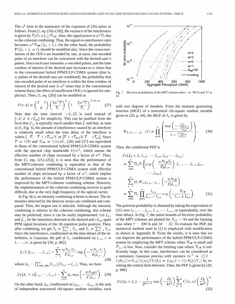
Fig. 7. Bit-error probabilities of the MPT scheme when� = 200 fs andM =
32.
with two degrees of freedom. From the moment generatingfunction (MGF) of a noncentral chi-square random variablegiven in [20, p. 44], the MGF of is given by
(30)
Then, the conditional PEP is
(31)
The pairwise probability is obtained by taking the expectation of(31) over , , or equivalently, over thetime delays. In Fig. 7, the union bounds of bit-error probabilityof the MPT schemes are plotted for and the limitingcase when fs and . To evaluate the PEP, thenumerical method used in [1] is employed with modificationas shown in Appendix B. From the results, it is seen that wecan improve the performance of the hybrid PPM/ULP-CDMAsystem by employing the MPT scheme when is small and
is low. Now, consider the limiting case where is suf-ficiently large. In this case, interference can be considered asa stationary Gaussian process with variance
by in-voking the central limit theorem. Then, the PEP is given by [20,p. 686]
(32)
1144 IEEE TRANSACTIONS ON COMMUNICATIONS, VOL. 51, NO. 7, JULY 2003
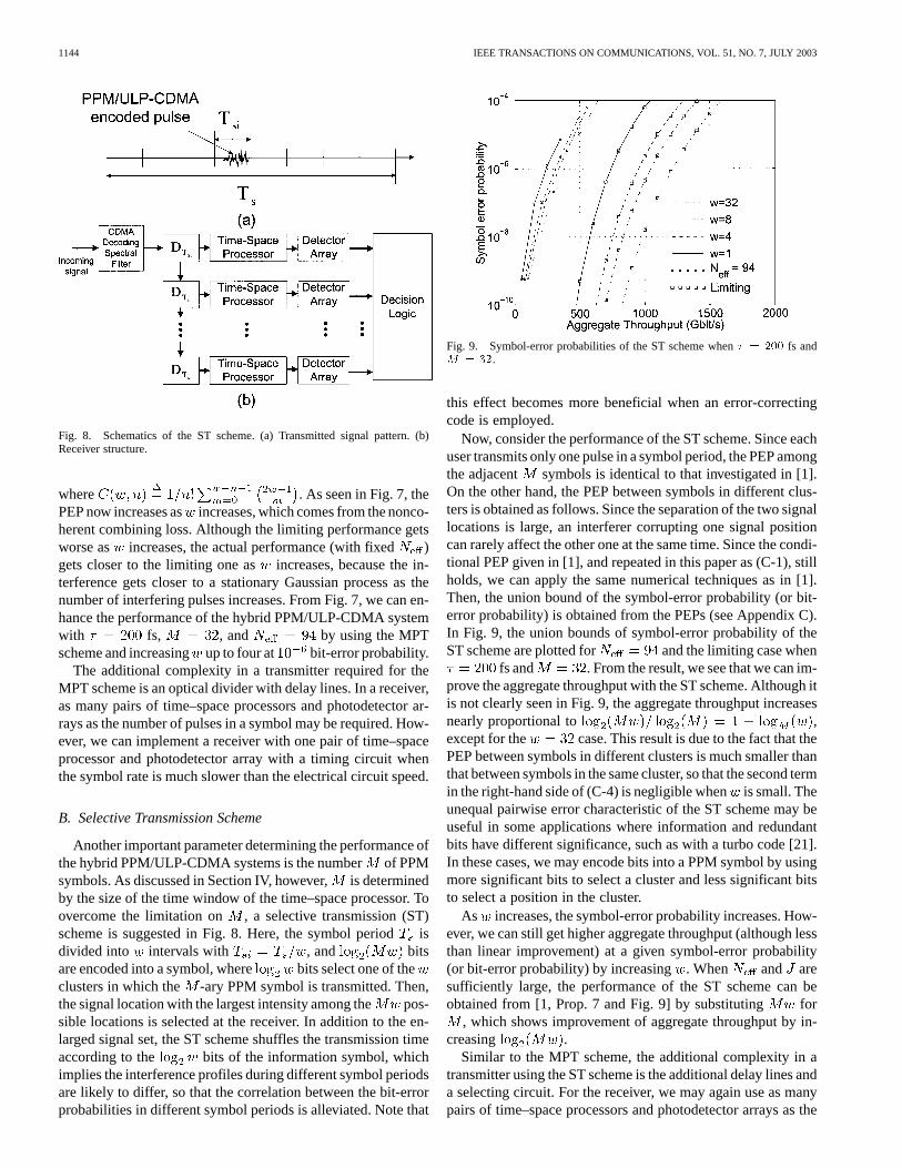
Fig. 8. Schematics of the ST scheme. (a) Transmitted signal pattern. (b)Receiver structure.
where . As seen in Fig. 7, thePEP now increases asincreases, which comes from the nonco-herent combining loss. Although the limiting performance getsworse as increases, the actual performance (with fixed )gets closer to the limiting one as increases, because the in-terference gets closer to a stationary Gaussian process as thenumber of interfering pulses increases. From Fig. 7, we can en-hance the performance of the hybrid PPM/ULP-CDMA systemwith fs, , and by using the MPTscheme and increasingup to four at bit-error probability.
The additional complexity in a transmitter required for theMPT scheme is an optical divider with delay lines. In a receiver,as many pairs of time–space processors and photodetector ar-rays as the number of pulses in a symbol may be required. How-ever, we can implement a receiver with one pair of time–spaceprocessor and photodetector array with a timing circuit whenthe symbol rate is much slower than the electrical circuit speed.
B. Selective Transmission Scheme
Another important parameter determining the performance ofthe hybrid PPM/ULP-CDMA systems is the numberof PPMsymbols. As discussed in Section IV, however,is determinedby the size of the time window of the time–space processor. Toovercome the limitation on , a selective transmission (ST)scheme is suggested in Fig. 8. Here, the symbol periodisdivided into intervals with , and bitsare encoded into a symbol, where bits select one of theclusters in which the -ary PPM symbol is transmitted. Then,the signal location with the largest intensity among the pos-sible locations is selected at the receiver. In addition to the en-larged signal set, the ST scheme shuffles the transmission timeaccording to the bits of the information symbol, whichimplies the interference profiles during different symbol periodsare likely to differ, so that the correlation between the bit-errorprobabilities in different symbol periods is alleviated. Note that
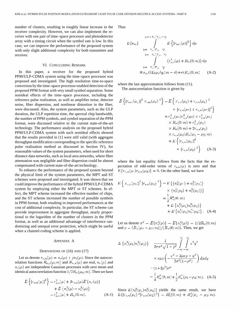
Fig. 9. Symbol-error probabilities of the ST scheme when� = 200 fs andM = 32.
this effect becomes more beneficial when an error-correctingcode is employed.
Now, consider the performance of the ST scheme. Since eachuser transmits only one pulse in a symbol period, the PEP amongthe adjacent symbols is identical to that investigated in [1].On the other hand, the PEP between symbols in different clus-ters is obtained as follows. Since the separation of the two signallocations is large, an interferer corrupting one signal positioncan rarely affect the other one at the same time. Since the condi-tional PEP given in [1], and repeated in this paper as (C-1), stillholds, we can apply the same numerical techniques as in [1].Then, the union bound of the symbol-error probability (or bit-error probability) is obtained from the PEPs (see Appendix C).In Fig. 9, the union bounds of symbol-error probability of theST scheme are plotted for and the limiting case when
fs and . From the result, we see that we can im-prove the aggregate throughput with the ST scheme. Although itis not clearly seen in Fig. 9, the aggregate throughput increasesnearly proportional to ,except for the case. This result is due to the fact that thePEP between symbols in different clusters is much smaller thanthat between symbols in the same cluster, so that the second termin the right-hand side of (C-4) is negligible whenis small. Theunequal pairwise error characteristic of the ST scheme may beuseful in some applications where information and redundantbits have different significance, such as with a turbo code [21].In these cases, we may encode bits into a PPM symbol by usingmore significant bits to select a cluster and less significant bitsto select a position in the cluster.
As increases, the symbol-error probability increases. How-ever, we can still get higher aggregate throughput (although lessthan linear improvement) at a given symbol-error probability(or bit-error probability) by increasing. When and aresufficiently large, the performance of the ST scheme can beobtained from [1, Prop. 7 and Fig. 9] by substituting for
, which shows improvement of aggregate throughput by in-creasing .
Similar to the MPT scheme, the additional complexity in atransmitter using the ST scheme is the additional delay lines anda selecting circuit. For the receiver, we may again use as manypairs of time–space processors and photodetector arrays as the
KIM et al.: HYBRID PULSE POSITION MODULATION/ULTRASHORT LIGHT PULSE CODE-DIVISION MULTIPLE-ACCESS SYSTEMS—PART II 1145
number of clusters, resulting in roughly linear increase in thereceiver complexity. However, we can also implement the re-ceiver with one pair of time–space processor and photodetectorarray with a timing circuit when the symbol rate is low. In thiscase, we can improve the performance of the proposed systemwith only slight additional complexity for both transmitter andreceiver.
VI. CONCLUDING REMARK
In this paper, a receiver for the proposed hybridPPM/ULP-CDMA system using the time–space processor wasproposed and investigated. The high resolution time-to-spaceconversion by the time–space processor enabled detection of theproposed PPM format with very small symbol separation. Somenonideal effects of the time–space processor, including thereference pulse realization, as well as amplifier noise, detectornoise, fiber dispersion, and nonlinear distortion in the fiber,were discussed. Also, the system parameters, such as the ULPduration, the ULP repetition time, the spectral chip bandwidth,the number of PPM symbols, and symbol separation of the PPMformat, were discussed relative to the current state-of-the-arttechnology. The performance analysis on the proposed hybridPPM/ULP-CDMA system with such nonideal effects showedthat the results provided in [1] were still valid (with aggregatethroughput modification corresponding to the specific referencepulse realization method as discussed in Section IV), forreasonable values of the system parameters, when used for shortdistance data networks, such as local area networks, where fiberattenuation was negligible and fiber dispersion could be almostcompensated with current state-of-the-art technology.
To enhance the performance of the proposed system beyondthe physical limit of the system parameters, the MPT and STschemes were proposed and investigated. It was shown that wecould improve the performance of the hybrid PPM/ULP-CDMAsystem by employing either the MPT or ST schemes. In ef-fect, the MPT scheme increased the effective number of chips,and the ST scheme increased the number of possible symbolsin PPM format, both resulting in improved performances at thecost of additional complexity. In particular, the ST scheme canprovide improvement in aggregate throughput, nearly propor-tional to the logarithm of the number of clusters in the PPMformat, as well as an additional advantage of interference ran-domizing and unequal error protection, which might be usefulwhen a channel-coding scheme is applied.
APPENDIX A
DERIVATIONS OF (16) AND (17)
Let us denote . Since the autocor-relation functions and are real, and
are independent Gaussian processes with zero mean andidentical autocorrelation function . Then we have
(A-1)
Thus
(A-2)
where the last approximation follows from (11).The autocorrelation function is given by
(A-3)
where the last equality follows from the facts that the ex-pectation of odd-order terms of is zero and that
. On the other hand, we have
(A-4)
Let us denoteand . Then, we get
(A-5)
Since yields the same result, we have.
1146 IEEE TRANSACTIONS ON COMMUNICATIONS, VOL. 51, NO. 7, JULY 2003
Therefore, we have
(A-6)
where the last approximation also follows from (11).
APPENDIX B
EVALUATION OF THE UNION BOUND ON THE BIT-ERROR
PROBABILITY IN THE MPT SCHEME
Since we have OOCs and users, an OOC is assigned tousers in a group, where denotes the smallest in-
teger greater than. Then, an interferer from other groups cancorrupt one pulse of the desired user with probability[19]. On the other hand, an interferer from the same group cancorrupt one pulse and all pulses of the desired user with prob-ability and , respectively. Let , , andbe the numbers of -pulse corrupting interferers from the samegroup, one-pulse corrupting interferers from the same group,and one-pulse corrupting interferers from another group, respec-tively. Then, the probability of this event is
(B-1)
where . For given values of , , and ,we generate with uniform distribution over .We also select equiprobably to locate thethinterferer around the th pulse location of the desired user. Wethen evaluate
and. Here, we ig-
nore sidelobes of the function, as we did in [1]. Then,we evaluate (31) and average it over 10 000 trials to obtain
. Note that .Finally, the unconditional PEP and the union bound of thebit-error probability are obtained as
(B-2)
and
(B-3)
respectively, where is the average number of bit errors pernumber of bits in a symbol, caused by falsely detecting a symbolthat is apart from the desired symbol.
APPENDIX C
EVALUATION OF THE UNION BOUND ON THE SYMBOL-ERROR
PROBABILITY IN THE ST SCHEME
The conditional PEP is given by [1]
(C-1)where and are the transmitted and some other signal loca-tions, respectively, and and are the effective numbers ofinterferers at the two signal locations, defined in [1]. Here, thesubscript is used to emphasize that the other signal locationis in a different cluster. When the two signal locations are inthe same cluster separated by (subscript is used insteadof in this case), the PEP is evaluated as in [1]. When the twosignals are in different clusters with , we can assumethat an interferer that affects one signal location cannot affectthe other signal location. Then, a modified version of the nu-merical method in [1] is applied to evaluate the PEP as follows.First, we assume that only interferers with time delays within
of the two signal locations and are taken intoaccount for and , respectively. Let and be the numberof interferers with relative time delays within of and .Then, we have
(C-2)
For given values of and , we generate with auniform distribution over . Next, we evaluate
and . Then,we evaluate (C-1) and average it over 10 000 trials to obtain
. Again, note that .Finally, the unconditional PEP is obtained as
(C-3)
KIM et al.: HYBRID PULSE POSITION MODULATION/ULTRASHORT LIGHT PULSE CODE-DIVISION MULTIPLE-ACCESS SYSTEMS—PART II 1147
Since the PEP is the same for all signal locations thatare not in the same cluster of, the symbol-error probability,
, is given by
(C-4)where the first term is the sum of PEP due to the signal locationsin the same cluster, given in [1].
REFERENCES
[1] K. S. Kim, D. M. Marom, L. B. Milstein, and Y. Fainman, “Hybrid pulseposition modulation/ultrashort light pulse code-division multiple-accesssystems—Part I: Fundamental analysis,”IEEE Trans. Commun, vol. 50,pp. 2018–2031, Dec. 2002.
[2] P. C. Sun, Y. T. Mazurenko, and Y. Fainman, “Femtoscale pulseimaging: ultrafast optical oscilloscope,”J. Opt. Soc. Amer. A, vol. 14,pp. 1159–1170, May 1997.
[3] D. M. Marom, D. Panasenko, P. C. Sun, and Y. Fainman, “Linear andnonlinear operation of a time-to-space processor,”J. Opt. Soc. Amer. A.,vol. 18, pp. 448–458, Feb. 2001.
[4] J. W. Goodman,Introduction to Fourier Optics. New York: McGraw-Hill, 1968.
[5] E. Desurvire,Erbium Doped Fiber Amplifiers, Principles and Applica-tions. New York: Wiley, 1994.
[6] S. Shen, C.-C. Chang, H. P. Sardesai, V. Binjrajka, and A. M. Weiner,“Effects of self-phase modulation on sub-500 fs pulse transmission overdispersion compensated fiber links,”J. Lightwave Technol., vol. 17, pp.452–461, Mar. 1999.
[7] G. P. Agrawal, Fiber-Optic Communication Systems. New York:Wiley, 1993.
[8] H. J. Landau and H. O. Pollak, “Prolate spheroidal wave functions,Fourier analysis and uncertainty—III: the dimension of the space ofessentially time- and band-limited signals,”Bell Syst. Tech. J., vol. 41,pp. 1295–1336, July 1962.
[9] P. A. Humblet and M. Azizoglu, “On the bit-error rate of lightwavesystems with optical amplifiers,”J. Lightwave Technol., vol. 9, pp.1576–1582, Nov. 1991.
[10] J.-S. Lee and C.-S. Shim, “Bit-error rate analysis of optically preampli-fied receivers using an eigenfunction expansion method in optical fre-quency domain,”J. Lightwave Technol., vol. 12, pp. 1224–1229, July1994.
[11] S. Herbst, M. Baussman, and M. Erbacsh, “Sensitivity of a direct WDM-system with a frequency-selective optical receiver and optical preampli-fier,” J. Lightwave Technol., vol. 12, pp. 32–36, Jan. 1998.
[12] M. Nakazawa, E. Yoshida, T. Yamamoto, E. Yamada, and A. Sahara,“TDM single channel 640 Gbit/s transmission experiment over 60 kmusing 400 fs pulse train and walk-off free, dispersion flattened nonlinearoptical loop minor,”Electron. Lett., vol. 34, pp. 907–908, Apr. 1998.
[13] C.-C. Chang and A. M. Weiner, “Fiber transmission for sub-500-fspulses using a dispersion-compensating fiber,”IEEE J. QuantumElectron., vol. 33, pp. 1455–1464, Sept. 1997.
[14] Y. Ding, A. M. Weiner, M. R. Melloch, and D. D. Nolte, “Adaptive all-order dispersion compensation of ultrafast laser pulses using dynamicspectral holography,”Appl. Phys. Lett., vol. 75, pp. 3255–3257, Nov.1999.
[15] P. C. Sun, Y. T. Mazurenko, and Y. Fainman, “Real-time one-dimen-sional coherent imaging through single-mode fibers by space–time con-version processors,”Opt. Lett., vol. 22, pp. 1861–1863, Dec. 1997.
[16] G. Lenz, K. Tamura, H. A. Haus, and E. P. Ippen, “All-solid-state fem-tosecond source at 1.55 mu m,”Opt. Lett., vol. 20, pp. 1289–1291, June1995.
[17] E. Yoshida and M. Nakazawa, “Ultrashort pulse generation at high rep-etition rate from mode-locked fiber lasers,”Rev. Laser Eng., vol. 27, pp.274–280, Nov. 1999.
[18] T. Kurokawa, H. Tsuda, K. Okamoto, K. Naganuma, H. Takenouchi,Y. Inoue, and M. Ishii, “Time–space-conversion optical signal pro-cessing using arrayed-waveguide grating,”Electron. Lett., vol. 33, pp.1890–1891, Oct. 1997.
[19] J. A. Salehi, “Code-division multiple-access techniques in optical fibernetwork—Part I: Fundamental principles,”IEEE Trans. Commun., vol.37, pp. 824–833, Aug. 1989.
[20] J. G. Proakis,Digital Communication, 3rd ed. New York: McGraw-Hill, 1995.
[21] A. H. S. Mohammadi and A. K. Khandani, “Unequal error protectionon turbo-encoder output bits,”Electron. Lett., vol. 33, pp. 273–274, Feb.1997.
Kwang Soon Kim (S’94–M’99) was born in Seoul,Korea, on September 20, 1972. He received the B.S.(summa cum laude), M.S.E., and Ph.D. degrees inelectrical engineering from the Korea Advanced In-stitute of Science and Technology (KAIST), Daejeon,Korea, in 1994, 1996, and 1999, respectively.
He was a Teaching and Research Assistant at theDepartment of Electrical Engineering, KAIST, fromMarch 1994 to February 1999. From March 1999 toMarch 2000, he was with the Department of Elec-trical and Computer Engineering, University of Cal-
ifornia at San Diego, La Jolla, as a Postdoctoral Researcher. In April 2000,he joined the Mobile Telecommunication Research Laboratory, Electronics andTelecommunication Research Institute, Daejeon, Korea, where he is currentlya Senior Member of Research Staff. His research interests include detectionand estimation theory, channel coding and iterative decoding, array signal pro-cessing, wireless/optical CDMA systems, wireless CDMA MODEM design anddevelopment, and wireless OFDM systems.
Dr. Kim received the Postdoctoral Fellowship from the Korea Science andEngineering Foundation (KOSEF) in 1999. He also received the Silver Prize atthe Humantech Paper Contest in 1998, the Silver Prize at the LG Information andCommunications Paper Contest in 1998, and the Best Researcher Award fromthe Electronics and Telecommunication Research Institute (ETRI) in 2002.
Dan M. Marom (S’98–M’01) was born in Detroit,MI, in 1967. He received the B.Sc. and M.Sc.degrees from Tel-Aviv University, Tel-Aviv, Israel,in 1989 and 1995, respectively, and the Ph.D.degree from the University of California, San Diego(UCSD), in 2000. His doctoral dissertation dealtwith femtosecond-rate optical signal processing withapplications in ultrafast communications.
From 1996 through 2000, he was a Fannie andJohn Hertz Foundation Graduate Fellow at UCSD.In 2000, he joined Bell Laboratories, Holmdel, NJ,
to pursue his interests in optical communications.Dr. Marom received the IEEE Lasers and Electro-Optics Society Best Student
Paper Award in 1999.
Laurence B. Milstein (S’66–M’68–SM’77–F’85)received the B.E.E. degree from the City Collegeof New York, New York, NY, in 1964, and the M.S.and Ph.D. degrees in electrical engineering from thePolytechnic Institute of Brooklyn, Brooklyn, NY, in1966 and 1968, respectively.
From 1968 to 1974, he was with the Spaceand Communications Group of Hughes AircraftCompany, and from 1974 to 1976, he was a memberof the Department of Electrical and SystemsEngineering, Rensselaer Polytechnic Institute,
Troy, NY. Since 1976, he has been with the Department of Electrical andComputer Engineering, University of California at San Diego, La Jolla, wherehe is a Professor and former Department Chairman, working in the area ofdigital communication theory with special emphasis on spread-spectrumcommunication systems. He has also been a consultant to both government andindustry in the areas of radar and communications.
1148 IEEE TRANSACTIONS ON COMMUNICATIONS, VOL. 51, NO. 7, JULY 2003
Dr. Milstein was an Associate Editor for Communication Theory for theIEEE TRANSACTIONS ONCOMMUNICATIONS, an Associate Editor for Book Re-views for the IEEE TRANSACTIONS ON INFORMATION THEORY, an AssociateTechnical Editor for theIEEE Communications Magazine, and the Editor-in-Chief of the IEEE JOURNAL ON SELECTEDAREAS INCOMMUNICATIONS. He wasthe Vice President for Technical Affairs in 1990 and 1991 of the IEEE Commu-nications Society, and has been a member of the Board of Governors of both theIEEE Communications Society and the IEEE Information Theory Society. Heis a former Chair of the IEEE Fellows Selection Committee, and a former Chairof ComSoc’s Strategic Planning Committee. He is a recipient of the 1998 Mil-itary Communications Conference Long Term Technical Achievement Award,an Academic Senate 1999 UCSD Distinguished Teaching Award, an IEEE ThirdMillenium Medal in 2000, the 2000 IEEE Communication Society ArmstrongTechnical Achievement Award, and the 2002 MILCOM Fred Ellersick Award.
Yeshaiahu Fainman(M’93–SM’01–F’03) receivedthe Ph.D. degree from Technion-Israel Institute ofTechnology, Haifa, Israel, in 1983.
He is a Professor of Electrical and ComputerEngineering at the University of California at SanDiego, La Jolla. His current research interestsare in nonlinear space–time processes using fem-tosecond laser pulses for optical communications,near-field phenomena in optical nanostructuresand nanophotonic devices, quantum cryptographyand communication, 3-D quantitative imaging,
programmable, multifunctional diffractive, and nonlinear optics. He con-tributed over 100 manuscripts in referred journals and over 170 conferencepresentations and conference proceedings. Between 1993–2001, he served as aTopical Editor of theJournal of the Optical Society of America: Aon OpticalSignal Processing and Imaging Science.
Dr. Fainman is a Fellow of the Optical Society of America and a recipient ofthe Miriam and Aharon Gutvirt Prize. He served on several conferences’ pro-gram committees, and organized symposia and workshops.