Embed Size (px)
Citation preview
AIRTEC column ejectorsVacuum generators with 1,4, 6 and 8 independentvacuum circuits.
SeriesHV and HF
Page 10.010
MI and MIFPage 10.015
AIRTECclassic ejectors
Page 10.001
Air. Pressure. Motion. n n n n n n n n
Vacuum switchesPage 10.040
Accessories forvacuum technology
Page 10.041
AIRTECcentral ejectorsVacuum generators available with– Blow off function– Air saving circuit– Integrated vacuum
switches– Control valves
Page 10.030
Series HVBMCentral ejectorsaccording to the Venturiprinciple, incl. solenoidpilot valves for mountingon RF manifold system.
Page 10.020
10.000

A
AIRTEC Classic ejectors
FunctionAIRTEC Classic ejectors work according to the Venturi principle. Air compressed between 4 and 6 bar, which isas dirt and oil free as possible, flows through the Venturi nozzle (B) via the compressed air supply (A); this isprotected against large particles of dirt by a protective filter.As a result of the flow cross-section in the nozzle being narrowed considerably, the flow velocity increases to thesupersonic level.In the mixing chamber (C), the quick-moving air jet hits the atmospheric air of the vacuum line (D) and whisksthis along into the up-take nozzle (E), also known as a diffuser.In this process, the required negative pressure is creating vacuum. A protective filter in the vacuum connection(D) prevents large particles of dirt getting into the vacuum area, thus preventing malfunctions in the mixing cham-ber (C), which can lead to the vacuum failing to be generated.The granular silencer in the exhaust air outlet (F) reduces the noise of the exhaust air flow and allows the finedirt from the vacuum area to pass without resistance. With the protective filters in (A) and (D) a longer servicecycle is achieved.By installing a blow off valve in the exhaust air outlet (F), the vacuum can be dispelled very quickly. It frees thework piece from the suction cup or ventilates the container and simultaneously blows the dirt from the protec-tive filter.
HV-… and HF-…
BC
D E F
Applications• Handling- and mounting application• Transport- and conveyer systems• Metal- and wood working industry• Automobile industry
• Pharmaceutical- and food industry• Packaging industry• Manipulators• Robotics
DesignHV Classic ejectors.Vacuum generator according to the Venturi Principle: high vacuum performance with low compressed air con-sumption.HF Classic ejectors.Anodised aluminium body, hexagon-shape; compact and robust construction.Quick and easy assembly with direct or indirect mounting at the place of installation.Vacuum generator according to the Venturi Principle: higher vacuum performance compared to HV-133/333/533with the same low compressed air consumption. Connections 1 and 2 are fitted with removable protective filtersto protect the ejector from debris.The ejector is supplied complete with the silencer.
10.001
10
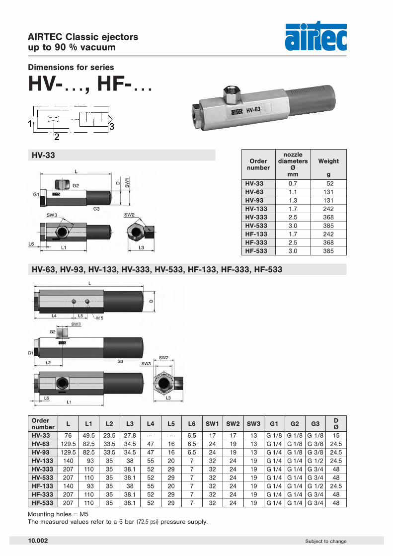
AIRTEC Classic ejectorsup to 90 % vacuum
Dimensions for series
HV-…, HF-…
HV-63, HV-93, HV-133, HV-333, HV-533, HF-133, HF-333, HF-533
Order L L1 L2 L3 L4 L5 L6 SW1 SW2 SW3 G1 G2 G3 Dnumber ØHV-33 76 49.5 23.5 27.8 – – 6.5 17 17 13 G 1/8 G 1/8 G 1/8 15HV-63 129.5 82.5 33.5 34.5 47 16 6.5 24 19 13 G 1/4 G 1/8 G 3/8 24.5HV-93 129.5 82.5 33.5 34.5 47 16 6.5 24 19 13 G 1/4 G 1/8 G 3/8 24.5HV-133 140 93 35 38 55 20 7 32 24 19 G 1/4 G 1/4 G 1/2 24.5HV-333 207 110 35 38.1 52 29 7 32 24 19 G 1/4 G 1/4 G 3/4 48HV-533 207 110 35 38.1 52 29 7 32 24 19 G 1/4 G 1/4 G 3/4 48HF-133 140 93 35 38 55 20 7 32 24 19 G 1/4 G 1/4 G 1/2 24.5HF-333 207 110 35 38.1 52 29 7 32 24 19 G 1/4 G 1/4 G 3/4 48HF-533 207 110 35 38.1 52 29 7 32 24 19 G 1/4 G 1/4 G 3/4 48
Mounting holes = M5The measured values refer to a 5 bar (72.5 psi) pressure supply.
HV-33 nozzleOrder diameters Weight
number Ømm g
HV-33 0.7 52HV-63 1.1 131HV-93 1.3 131HV-133 1.7 242HV-333 2.5 368HV-533 3.0 385HF-133 1.7 242HF-333 2.5 368HF-533 3.0 385
10.002 Subject to change

AIRTEC Classic ejectorsup to 90 % vacuum
Technical data for series
HV-133, HV-333, HV-533
HF-133, HF-333, HF-533
HV-33, HV-63, HV-93
10
10.003Subject to change
Time to evacuate a 1 litre vessel at 5 bar Vacuum flow at 5 bar
Sec
on
ds
Vacuum level (%) Vacuum level (%)
Vac
uu
m f
low
(N
l/m
in)
Max. Vacuum level Air consumption
Pressure (bar) Pressure (bar)
Max
. va
cuu
m l
evel
(%
)
Air
con
sum
ptio
n (N
l/m
in)
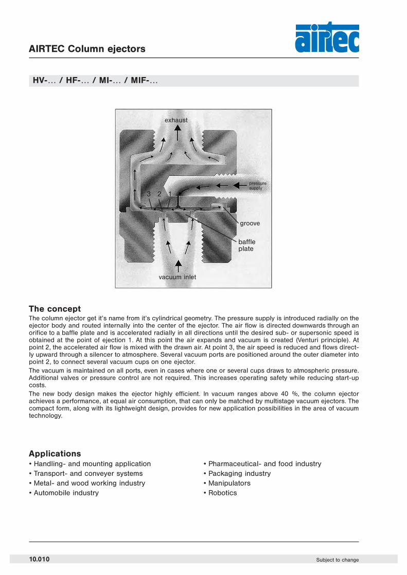
AIRTEC Column ejectors
The conceptThe column ejector get it’s name from it’s cylindrical geometry. The pressure supply is introduced radially on theejector body and routed internally into the center of the ejector. The air flow is directed downwards through anorifice to a baffle plate and is accelerated radially in all directions until the desired sub- or supersonic speed isobtained at the point of ejection 1. At this point the air expands and vacuum is created (Venturi principle). Atpoint 2, the accelerated air flow is mixed with the drawn air. At point 3, the air speed is reduced and flows direct-ly upward through a silencer to atmosphere. Several vacuum ports are positioned around the outer diameter intopoint 2, to connect several vacuum cups on one ejector.The vacuum is maintained on all ports, even in cases where one or several cups draws to atmospheric pressure.Additional valves or pressure control are not required. This increases operating safety while reducing start-upcosts.The new body design makes the ejector highly efficient. In vacuum ranges above 40 %, the column ejector achieves a performance, at equal air consumption, that can only be matched by multistage vacuum ejectors. Thecompact form, along with its lightweight design, provides for new application possibilities in the area of vacuumtechnology.
HV-… / HF-… / MI-… / MIF-…
Applications• Handling- and mounting application• Transport- and conveyer systems• Metal- and wood working industry• Automobile industry
• Pharmaceutical- and food industry• Packaging industry• Manipulators• Robotics
exhaust
vacuum inlet
groove
baffleplate
pressuresupply
3 2 1
10.010 Subject to change

High vacuum ejectorswith one vacuum connectionup to 85 % vacuum
Technical data and dimensions for series
HV-…, HF-…
Design and functionThe HV and HF series are based on the Venturi principle. The unitshave one air supply port (lateral), one exhaust port on top and onevacuum port (bottom). One additional lateral port for possible gaugemounting is plugged.The HV series is optimized for vacuum levels up to 85% at low airconsumption. The unit is mainly used for quick automation processes.The HF series provides a high air flow and is used for the handlingof porous parts like styrofoam, chipboard, cardboard etcThe unit is supplied complete with an: Acetal-resin silencer with self-cleaning granulate filling which is mounted on the exhaust port. Themodel HF-1150 and HF-1500 is equipped with a sintered bronzesilencer.Additional accessories please see page 10.042.
Order L L1 L2 Ø1 Ø2 SW G1 G2 G3 G4 Weightnumber kgHV-80 109 47 25 48 24,5 40 G 1/4 G 1/2 G 1/2 G 1/8 0.300 (0.661 lb.)
HV-150 109 47 25 48 24,5 40 G 1/4 G 1/2 G 1/2 G 1/8 0.300 (0.661 lb.)
HV-300 163 97 28 59 48 50 G 1/4 G 1 G 1 G 1/8 0.400 (0.882 lb.)
HV-600 163 97 28 59 48 50 G 1/4 G 1 G 1 G 1/8 0.400 (0.882 lb.)
HF-100 109 47 25 48 24,5 40 G 1/4 G 1/2 G 1/2 G 1/8 0.240 (0.529 lb.)
HF-200 163 97 28 59 48 50 G 1/4 G 1 G 1 G 1/8 0.400 (0.882 lb.)
HF-300 163 97 28 59 48 50 G 1/4 G 1 G 1 G 1/8 0.400 (0.882 lb.)
HF-450 163 97 28 59 48 50 G 1/4 G 1 G 1 G 1/8 0.400 (0.882 lb.)
HF-600 163 97 28 59 48 50 G 1/4 G 1 G 1 G 1/8 0.400 (0.882 lb.)
HF-1150 180 90 38 88 64 69 G 3/8 G 11/2 G 2 G 1/8 0.900 (1.984 lbs.)
HF-1500 180 90 38 88 64 69 G 3/8 G 11/2 G 2 G 1/8 0.900 (1.984 lbs.)
The measured values refer to a 5 bar (72.5 psi) pressure supply.
10.011Subject to change
10
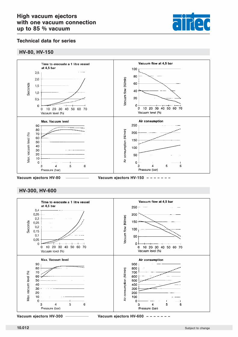
High vacuum ejectorswith one vacuum connectionup to 85 % vacuum
Technical data for series
HV-80, HV-150
HV-300, HV-600
Vacuum ejectors HV-80 Vacuum ejectors HV-150 – – – – – – –
Vacuum ejectors HV-300 Vacuum ejectors HV-600 – – – – – – –
10.012 Subject to change

High vacuum ejectorswith one vacuum connectionup to 85 % vacuum
Technical data for series
HF-100
HF-200, HF-300
Vacuum ejector HF-100
Vacuum ejectors HF-200 Vacuum ejectors HF-300 – – – – – – –
10.013Subject to change
10
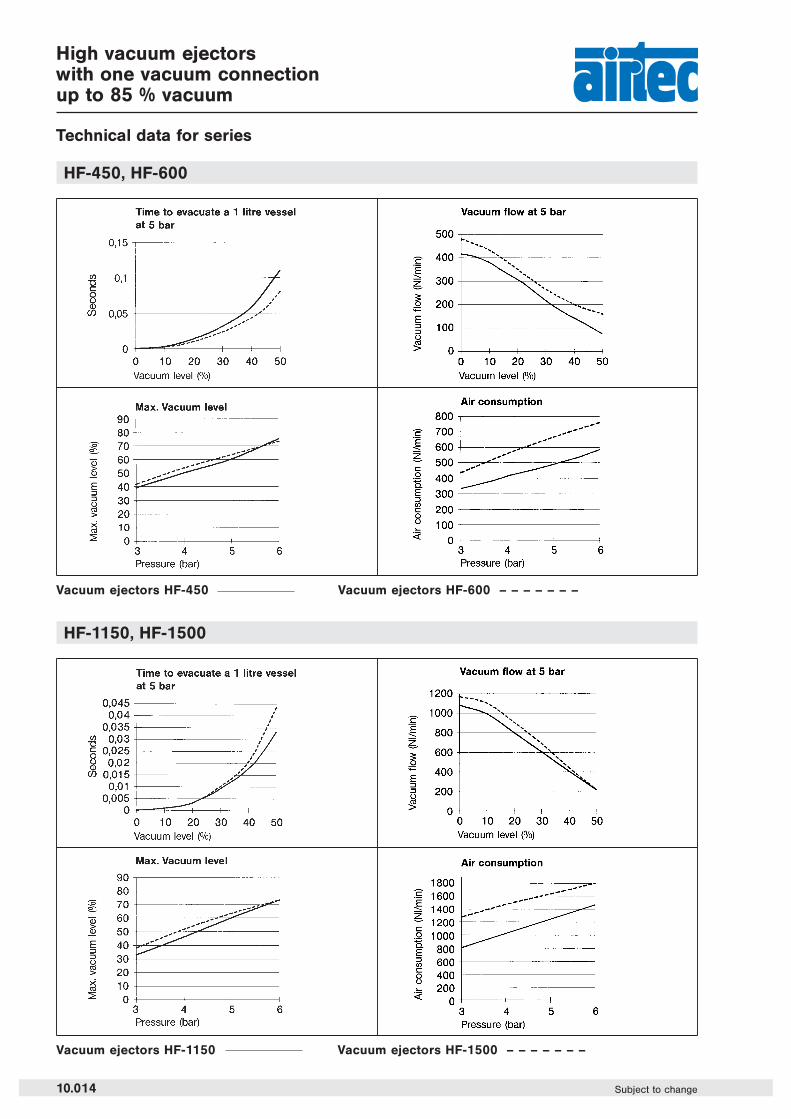
High vacuum ejectorswith one vacuum connectionup to 85 % vacuum
Technical data for series
HF-450, HF-600
HF-1150, HF-1500
Vacuum ejectors HF-450 Vacuum ejectors HF-600 – – – – – – –
Vacuum ejectors HF-1150 Vacuum ejectors HF-1500 – – – – – – –
10.014 Subject to change
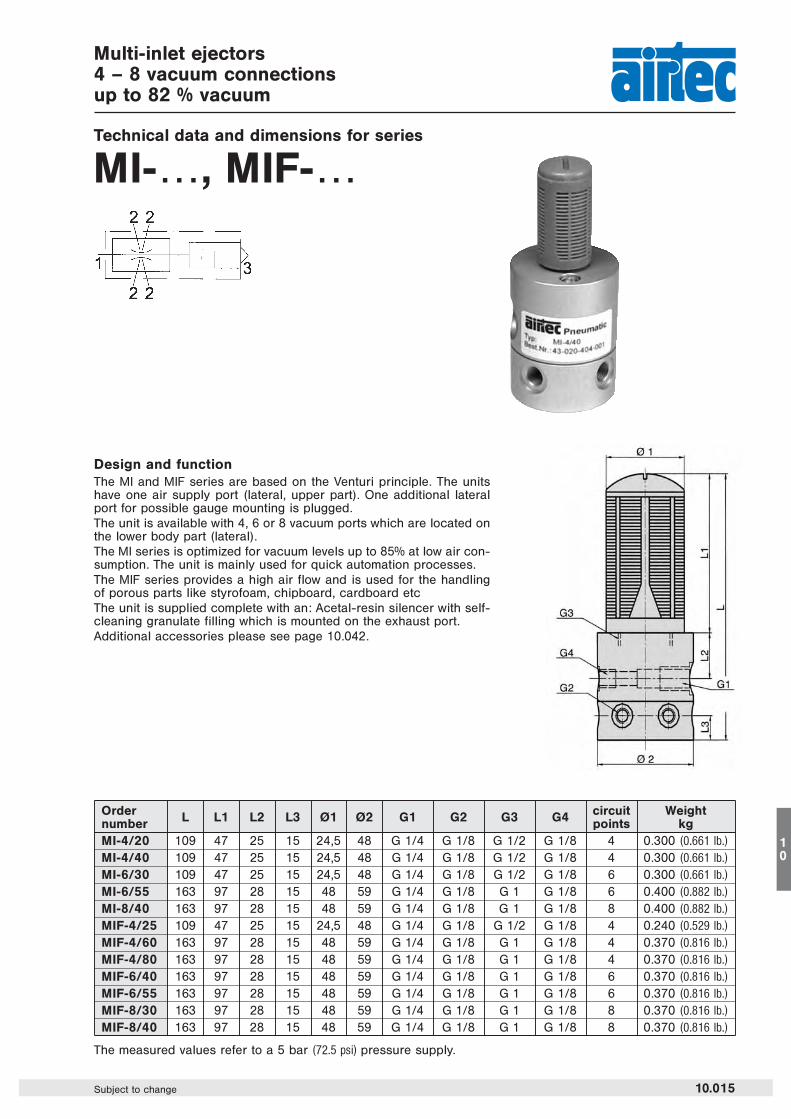
Multi-inlet ejectors4 – 8 vacuum connectionsup to 82 % vacuum
Technical data and dimensions for series
MI-…, MIF-…
Design and functionThe MI and MIF series are based on the Venturi principle. The unitshave one air supply port (lateral, upper part). One additional lateralport for possible gauge mounting is plugged.The unit is available with 4, 6 or 8 vacuum ports which are located onthe lower body part (lateral).The MI series is optimized for vacuum levels up to 85% at low air con-sumption. The unit is mainly used for quick automation processes.The MIF series provides a high air flow and is used for the handlingof porous parts like styrofoam, chipboard, cardboard etcThe unit is supplied complete with an: Acetal-resin silencer with self-cleaning granulate filling which is mounted on the exhaust port.Additional accessories please see page 10.042.
Order L L1 L2 L3 Ø1 Ø2 G1 G2 G3 G4 circuit Weightnumber points kgMI-4/20 109 47 25 15 24,5 48 G 1/4 G 1/8 G 1/2 G 1/8 4 0.300 (0.661 lb.)
MI-4/40 109 47 25 15 24,5 48 G 1/4 G 1/8 G 1/2 G 1/8 4 0.300 (0.661 lb.)
MI-6/30 109 47 25 15 24,5 48 G 1/4 G 1/8 G 1/2 G 1/8 6 0.300 (0.661 lb.)
MI-6/55 163 97 28 15 48 59 G 1/4 G 1/8 G 1 G 1/8 6 0.400 (0.882 lb.)
MI-8/40 163 97 28 15 48 59 G 1/4 G 1/8 G 1 G 1/8 8 0.400 (0.882 lb.)
MIF-4/25 109 47 25 15 24,5 48 G 1/4 G 1/8 G 1/2 G 1/8 4 0.240 (0.529 lb.)
MIF-4/60 163 97 28 15 48 59 G 1/4 G 1/8 G 1 G 1/8 4 0.370 (0.816 lb.)
MIF-4/80 163 97 28 15 48 59 G 1/4 G 1/8 G 1 G 1/8 4 0.370 (0.816 lb.)
MIF-6/40 163 97 28 15 48 59 G 1/4 G 1/8 G 1 G 1/8 6 0.370 (0.816 lb.)
MIF-6/55 163 97 28 15 48 59 G 1/4 G 1/8 G 1 G 1/8 6 0.370 (0.816 lb.)
MIF-8/30 163 97 28 15 48 59 G 1/4 G 1/8 G 1 G 1/8 8 0.370 (0.816 lb.)
MIF-8/40 163 97 28 15 48 59 G 1/4 G 1/8 G 1 G 1/8 8 0.370 (0.816 lb.)
The measured values refer to a 5 bar (72.5 psi) pressure supply.
10.015Subject to change
10
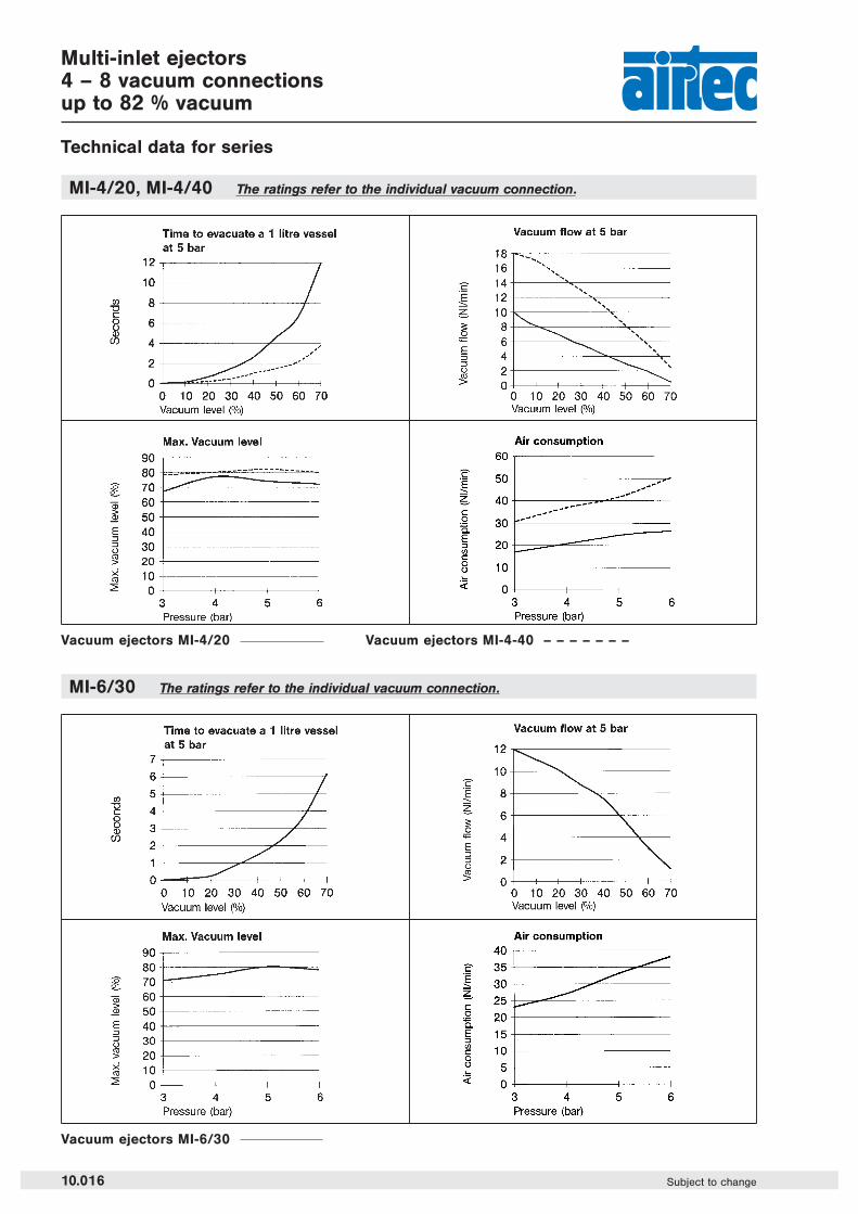
Multi-inlet ejectors4 – 8 vacuum connectionsup to 82 % vacuum
Technical data for series
MI-4/20, MI-4/40 The ratings refer to the individual vacuum connection.
MI-6/30 The ratings refer to the individual vacuum connection.
Vacuum ejectors MI-4/20 Vacuum ejectors MI-4-40 – – – – – – –
Vacuum ejectors MI-6/30
10.016 Subject to change
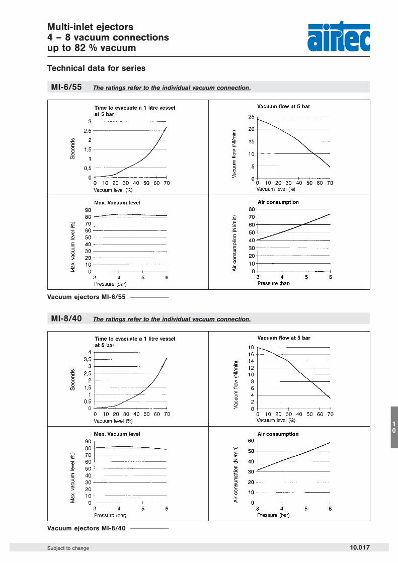
Multi-inlet ejectors4 – 8 vacuum connectionsup to 82 % vacuum
Technical data for series
MI-6/55 The ratings refer to the individual vacuum connection.
MI-8/40 The ratings refer to the individual vacuum connection.
Vacuum ejectors MI-6/55
Vacuum ejectors MI-8/40
10.017Subject to change
10
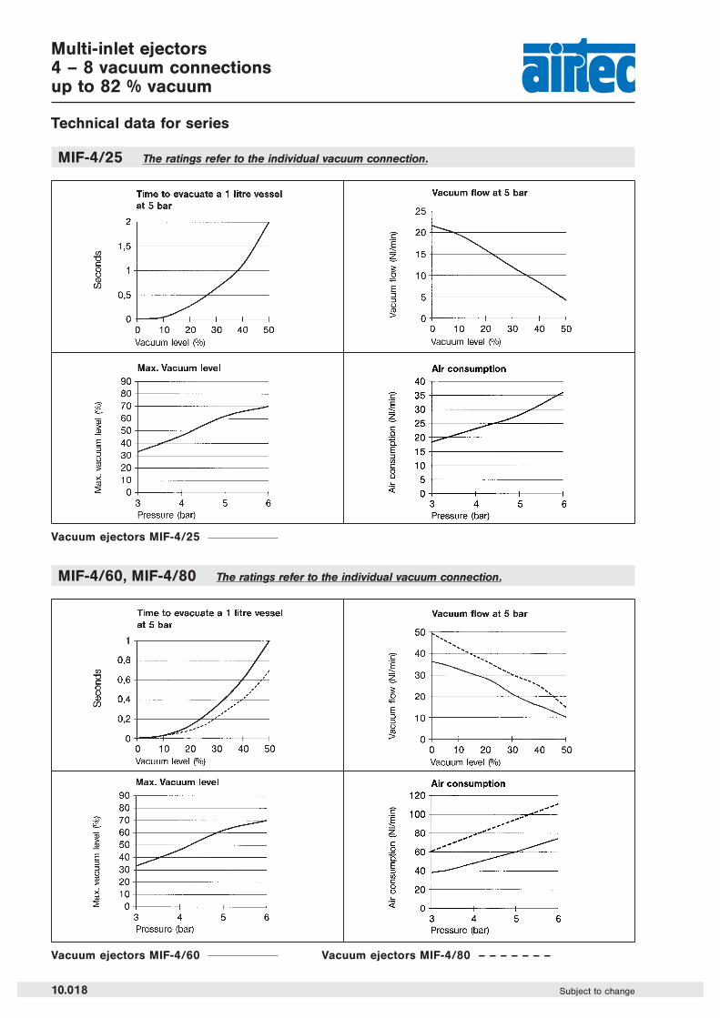
Multi-inlet ejectors4 – 8 vacuum connectionsup to 82 % vacuum
Technical data for series
MIF-4/25 The ratings refer to the individual vacuum connection.
MIF-4/60, MIF-4/80 The ratings refer to the individual vacuum connection.
Vacuum ejectors MIF-4/25
Vacuum ejectors MIF-4/60 Vacuum ejectors MIF-4/80 – – – – – – –
10.018 Subject to change

Multi-inlet ejectors4 – 8 vacuum connectionsup to 82 % vacuum
Technical data for series
MIF-6/40, MIF-6/55 The ratings refer to the individual vacuum connection.
MIF-8/30, MIF-8/40 The ratings refer to the individual vacuum connection.
Vacuum ejectors MIF-6/40 Vacuum ejectors MIF-6/55 – – – – – – –
Vacuum ejectors MIF-8/30 Vacuum ejectors MIF-8/40 – – – – – – –
Vacuumlevel forMIF-8/30and MIF-8/40is the same.
10.019Subject to change
10

Order number HVBM-33 HVBM-63 HVBM-93Please complete according to order code.
Pneumatic connection G 1/8 air supply and exhaust for single ejectorsG 1/4 air supply and exhaust for manifold mountingG 1/8 for vacuum port
Electrical connection Plug C according to DIN EN 175301-803
Vacuum level (at 4.5 bar) 87 % 89 % 92 %
Air consumption (vacuum 4.5 bar) 21 Nl/min (0.0213 Cv) 47 Nl/min (0.0478 Cv) 73,4 Nl/min (0.0745 Cv)
Air consumption (blow off at 4.5 bar) 79 Nl/min (0.0802 Cv) 65 Nl/min (0.0661 Cv) 90,9 Nl/min (0.0924 Cv)
Max. vacuum flow 13 Nl/min (0.0132 Cv) 33 Nl/min (0.0335 Cv) 48,3 Nl/min (0.0491 Cv)
Pressure range 4 … 6 bar (58 … 87 psi)
Temperature range 0 hC . . . + 50 hC (+ 32 °F … +122 °F)
Mounting Single mounting,Mounting on manifold with 4 x M5 or on DIN-rail
Materials Body: Al, brass and PA-GF; Inner parts: Al, stainless steel, brass, POM;Seals: PU, NBR
Degree of protection IP 65 according to EN 60529
Weight Single ejector: 0,3 kgMounting element: 0,07 kg + N x 0,04 kg (N = number of ejectors)
Central ejectorsup to 90 % vacuum
Technical data for series
HVBM
Design and functionThe central ejector is based on the Venturi principle. It is mounted on a RF- manifold system. A double 3/2-waypilot valve, type BM-01-310/2-HN, provides the control of the vacuum and blow off port.The unit is available as single ejector and can be extended up to 6 stations. 3 different flow sizes are available.Scope of delivery: Acetal-resin silence with self-cleaning granulate filling.
Order code HVBM-33-05-162
SeriesHVBM = Standard
Coil options
1) The solenoid can be supplied with plug socket connection and manual override on the same side as ports 2 and 4 or on thesame side as ports 1, 3 and 5.
When the valve is requested without the plug socket, the first digit of the order code for standard coils must be changed from1 to 4.
Information about the valves please see page 4.097.2) Please note, that the blow off function is only possible for a max. of 4 units at the same time if the full vacuum level has tobe maintained.3) SA = Element with pilot valve for single use.
SF = Element with pilot valve type BM-01-310/2-HN for mounting on manifold RF-01 (more valve information see page 4.090).
Standardvoltage
12 V DC, 1 W24 V DC, 1 W24 V AC, 3 VA115 V AC, 3 VA230 V AC, 3 VA
Plug socketupward 1)
161162152156157
Plug socket downward 1)
131132122126127
Number of stations02, 03, 04, 052, 062,SA3, SF3
Flow33 = 33 Nl/min63 = 63 Nl/min93 = 93 Nl/min
10.020 Subject to change

Central ejectorsup to 90 % vacuum
Dimensions for series
HVBMHVBM-33, HVBM-63, HVBM-93
1 = pressure inlet(2) = vacuum outlets3, 5 = exhausts(4) = exhaust ejector(7) = manual override(8) = solenoid for blow off(9) = solenoid for vacuum
N = number of ejectors (2 … 6)
Graph of size:
10.021Subject to change
10

AIRTEC Central ejectors
x System description of a central ejector
1.1 = Compressed air sucked in1.2 = Compressed air blow off2 = Vacuum connectionA = Venturi nozzleB = DiffuserC = Mixing chamberD = Check valvesE = Silencer
HV-P, -PVP, -PSU, -PSUVPSeries
Mechanical-pneumatical air saving device
10.030 Subject to change
Their functionThe AIRTEC central ejectors function according tothe Venturi principle. Compressed air with 4 to 6 barflows through a protective filter in the compressedair supply port (1.1) into the ejector creating a vac-uum in the mixing chamber (C). The vacuum line isevacuated via connection (2) and another protectivefilter.
A check valve (D) between the mixing chamber (C)and connection (2) as well as in connection (1.2)seal off the vacuum system to the atmosphere so thatin the event of the compressed air supply beinginterrupted in an airtight vacuum system, the vacuumremains unaffected.
To this end, the production series HV-SA withflange-mounted electronic vacuum switches has a
parts control or an electronically controlled savercircuit with parts control.
With an integrated mechanical-pneumatic vacuumregulator, the production series HV-P is able tocarry out an automatic saving function. Electronicvacuum switches also enable a parts control.
An air blast in connection (1.2), which also has aprotective filter fitted against the infiltration of dirt,quickly relieves the vacuum and in the process, alsocleans the protective filter in (2).
All ejector models can also be delivered with inte-grated solenoid valves, in the form of a compact unit.
A fully pneumatic ejector control system with a pneu-matic vacuum switch is possible on request.

HV-P, -PVP, -PSU, -PSUVP
AIRTEC Central ejectorsup to 80 % vacuum
Technical data for series
Order code HV-P-150
Series Air consumption150 = 150 Nl/min
(0.152 Cv)
300 = 300 Nl/min(0.305 Cv)
500 = 500 Nl/min(0.508 Cv)
FunctionsP = Vacuum, air-saving automatic function and blow off,
without vacuum switchPVP = Vacuum, air-saving automatic and blow off function
with additional control system for the air saving deviceand parts control
PSU = Vacuum, air-saving automatic function, blow off inter-ruption 0.3 s, without vacuum switch
PSUVP = Vacuum, air-saving automatic function, blow off inter-ruption 0.3 s, with adjustable vacuum sensor for partscontrol and air saving device
(CircuitHV-PVP)
Max. vacuum level HV-P-150 see HV-133 (Page 10.003)Max. vacuum level HV-P-300 see HV-333 (Page 10.003)Max. vacuum level HV-P-500 see HV-533 (Page 10.003)
Mechanical-pneumatical air saving device
(CircuitHV-PSU)
10.031Subject to change
10
AIRTEC Central ejectorsup to 80 % vacuum
Dimensions for series
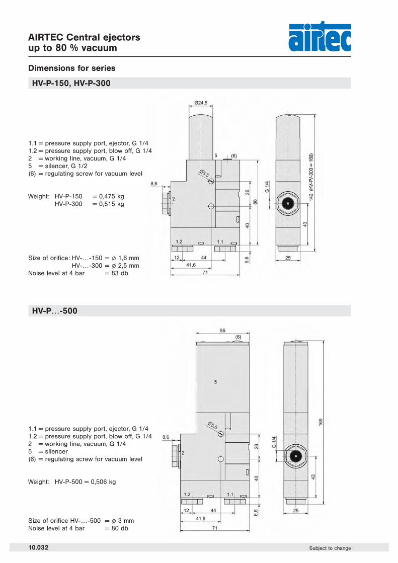
HV-P-150, HV-P-300
HV-P…-500
1.1 = pressure supply port, ejector, G 1/41.2 = pressure supply port, blow off, G 1/42 = working line, vacuum, G 1/45 = silencer, G 1/2(6) = regulating screw for vacuum level
1.1 = pressure supply port, ejector, G 1/41.2 = pressure supply port, blow off, G 1/42 = working line, vacuum, G 1/45 = silencer(6) = regulating screw for vacuum level
Weight: HV-P-150 = 0,475 kgHV-P-300 = 0,515 kg
Weight: HV-P-500 = 0,506 kg
Size of orifice: HV-…-150 = l 1,6 mmHV-…-300 = l 2,5 mm
Noise level at 4 bar = 83 db
Size of orifice HV-…-500 = l 3 mmNoise level at 4 bar = 80 db
10.032 Subject to change

Order number assembled with series A B C D EHV-P… 58.6 61.6 14.4
RHV-141/2HV-PSU…
68.2 25.180.6 83.6 14.4
HV-PA… 58.6 61.6 14.4RHV-141/3
HV-PSU…93.3 50.2
80.6 83.6 14.4HV-P… 58.6 61.6 14.4
RHV-141/4HV-PSU…
118.4 75.380.6 83.6 14.4
HV-P… 58.6 61.6 14.4RHV-141/5
HV-PSU…143.5 100.4
80.6 83.6 14.4HV-P… 58.6 61.6 14.4
RHV-141/6HV-PSU…
168.6 125.580.6 83.6 14.4
Accessoires forAIRTEC Central ejectors
Accessoires for series
HV-PP-manifolds
Manifold with hollow bolts and O-rings.Available from 2 to 6 stationsRHV-141/n
Hollow bolt with O-ringH-143
If requested, P-manifoldscan be delivered completewith pre-mountedcentral ejectors.
RHV-141/nP-manifold with hollow bolts and O-rings.Suitable for the mounting of central ejectors from the HV production series.Installation is also possible at connection 1.2 (blow off).Material: Al (anodized), O-rings: NBR, hollow bolts: brass.
Dimensions for P-manifold
RHV-141
10.033Subject to change
10
Electronic vacuum switch
Technical data for series
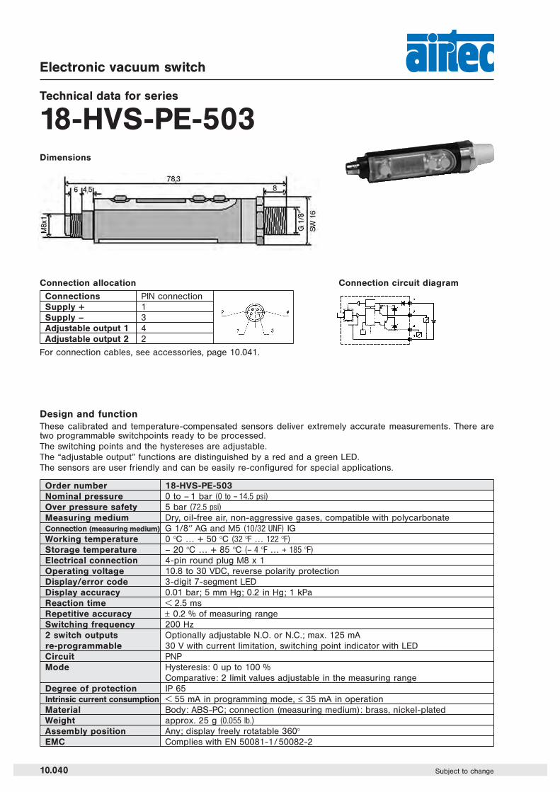
18-HVS-PE-503Dimensions
10.040 Subject to change
Connections PIN connectionSupply + 1Supply – 3Adjustable output 1 4Adjustable output 2 2
Order number 18-HVS-PE-503Nominal pressure 0 to – 1 bar (0 to – 14.5 psi)
Over pressure safety 5 bar (72.5 psi)
Measuring medium Dry, oil-free air, non-aggressive gases, compatible with polycarbonateConnection (measuring medium) G 1/8HH AG and M5 (10/32 UNF) IGWorking temperature 0 °C … + 50 °C (32 °F … 122 °F)
Storage temperature – 20 °C … + 85 °C (– 4 °F … + 185 °F)
Electrical connection 4-pin round plug M8 x 1Operating voltage 10.8 to 30 VDC, reverse polarity protectionDisplay/error code 3-digit 7-segment LEDDisplay accuracy 0.01 bar; 5 mm Hg; 0.2 in Hg; 1 kPaReaction time I 2.5 msRepetitive accuracy ± 0.2 % of measuring rangeSwitching frequency 200 Hz2 switch outputs Optionally adjustable N.O. or N.C.; max. 125 mAre-programmable 30 V with current limitation, switching point indicator with LEDCircuit PNPMode Hysteresis: 0 up to 100 %
Comparative: 2 limit values adjustable in the measuring rangeDegree of protection IP 65Intrinsic current consumption I 55 mA in programming mode, ≤ 35 mA in operationMaterial Body: ABS-PC; connection (measuring medium): brass, nickel-platedWeight approx. 25 g (0.055 lb.)
Assembly position Any; display freely rotatable 360°EMC Complies with EN 50081-1/ 50082-2
Design and functionThese calibrated and temperature-compensated sensors deliver extremely accurate measurements. There aretwo programmable switchpoints ready to be processed.The switching points and the hystereses are adjustable.The “adjustable output” functions are distinguished by a red and a green LED.The sensors are user friendly and can be easily re-configured for special applications.
Connection allocation Connection circuit diagram
For connection cables, see accessories, page 10.041.

Accessories for electronicvacuum switches/pressure switches
Adapter for the vacuum switch of the HV-SA/P ejector series
Adapter for the vacuum switch of the HV-SAVP/PV ejector series
Connection cablesfor all vacuum and pressure switches
Order number
28-HV-102 Cable length 2 m, cable socket M 8x1, straight 4-pin
28-HV-105 Cable length 5 m, cable socket M 8x1, straight 4-pin
28-HV-112 Cable length 2 m, cable socket M 8x1, angled 4-pin
28-HV-115 Cable length 5 m, cable socket M 8x1, angled 4-pin
03-1719-41
03-HV-18
1 = brown2 = white3 = blue4 = black
10.041Subject to change
10

Order number A B C SW L
43-274-14-18-01 8 G 1/4 G 1/8 17 1343-274-38-18-01 9 G 3/8 G 1/8 19 1443-274-38-14-01 9 G 3/8 G 1/4 19 1443-274-12-14-01 10 G 1/2 G 1/4 24 * 15,543-274-12-38-01 10 G 1/2 G 3/8 24 * 15,543-274-34-12-01 12 G 3/4 G 1/2 30 1743-274-10-12-01 13 G 1 G 1/2 36 1943-274-10-34-01 13 G 1 G 3/4 35 20
Protective filters for vacuum,vacuum and compressed air connection ports
Dimensions for
43-260-18
43-274Protective filter
Order number A B C D SW L
43-273-M5-18-01 4 M 5 2 G 1/8 13 1443-273-18-18-01 6 G 1/8 5 G 1/8 13 1643-273-18-14-01 6 G 1/8 5 G 1/4 17 1943-273-14-14-01 8 G 1/4 7 G 1/4 17 2143-273-14-38-01 8 G 1/4 7 G 3/8 19 2243-273-38-38-01 9 G 3/8 10 G 3/8 19 23
43-273Protective filter
Material: nickel-plated brass
* SW 24 = octagonAdditional protective filter on request.
Material: nickel-plated brass
Silencer series 40-90-… see page 11.121.
Brackets for classic and column ejectors with Ø 48 mm see page 8.086.
Brackets for column ejectors with Ø 59 mm see page 11.062.
Blow off valves see page 7.161.
10.042 Subject to change


![· VITRINES / DISPLAY C OUNTERS PRIMA PRIMA T [mm] [mm] [m²] ºC (3M1) 1.00m 1000 0.900 0.84 R134a/R290a +2÷+6 1.30m 1300 1200 1.06 R134a/R290a +2÷+6](https://img.pdfslide.us/doc/110x75/5e777c7a6a7a5758915cc9f9/vitrines-display-c-ounters-prima-prima-t-mm-mm-m-c-3m1-100m-1000.jpg)