Embed Size (px)
Citation preview
High Voltage Generatorand Voltage Divider for
10-stage PMT
hvBase-N-B14D10
©Bridgeport Instruments, LLC, hvBase – NegHV - B14D10 Version R1, 05/2010
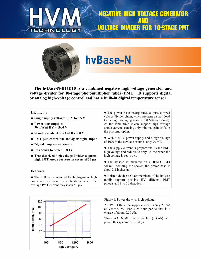
The hvBase-N-B14D10 is a combined negative high voltage generator and
voltage divider for 10-stage photomultiplier tubes (PMT). It supports digital
or analog high-voltage control and has a built-in digital temperature sensor.
Highlights
● Single supply voltage: 3.1 V to 5.5 V
● Power consumption:
70 mW at HV = 1000 V
● Standby mode: 0.5 mA at HV = 0 V
● PMT gain control via analog or digital input
● Digital temperature sensor
● Fits 2-inch to 5-inch PMTs
● Transistorized high voltage divider supports
high PMT anode currents in excess of 50 μA
Features
● The hvBase is intended for high-gain or high
count rate spectroscopy applications where the average PMT current may reach 50 μA.
● The power base incorporates a transistorized
voltage divider chain, which presents a small load to the high voltage generator (50 MΩ to ground). At the same time it can support high average anode currents causing only minimal gain drifts in the photomultiplier.
● With a 3.3 V power supply and a high voltage
of 1000 V the device consumes only 70 mW.
● The supply current is proportional to the PMT
high voltage and reduces to only 0.5 mA when the high voltage is set to zero.
● The hvBase is mounted on a JEDEC B14
socket. Including the socket, the power base is about 2.2 inches tall.
● Related devices: Other members of the hvBase
family support positive HV, different PMT pinouts and 8 to 10 dynodes.
Figure 1: Power draw vs. high voltage.
At HV = 1.0k V the supply current is only 21 mA at Vss = 3.3V. For a 24-hour period that is a charge of about 0.50 Ah.
Three AA NiMH rechargeables (1.8 Ah) will power this system for 3.6 days.
Negative High Voltage Generator and
Voltage Divider for 10-stage PMT
hvBase-NHigh Voltage Generatorand Voltage Divider for
10-stage PMT
hvBase-N-B14D10
©Bridgeport Instruments, LLC, hvBase – NegHV - B14D10 Version R1, 05/2010
The hvBase-N-B14D10 is a combined negative high voltage generator and
voltage divider for 10-stage photomultiplier tubes (PMT). It supports digital
or analog high-voltage control and has a built-in digital temperature sensor.
Highlights
● Single supply voltage: 3.1 V to 5.5 V
● Power consumption:
70 mW at HV = 1000 V
● Standby mode: 0.5 mA at HV = 0 V
● PMT gain control via analog or digital input
● Digital temperature sensor
● Fits 2-inch to 5-inch PMTs
● Transistorized high voltage divider supports
high PMT anode currents in excess of 50 μA
Features
● The hvBase is intended for high-gain or high
count rate spectroscopy applications where the average PMT current may reach 50 μA.
● The power base incorporates a transistorized
voltage divider chain, which presents a small load to the high voltage generator (50 MΩ to ground). At the same time it can support high average anode currents causing only minimal gain drifts in the photomultiplier.
● With a 3.3 V power supply and a high voltage
of 1000 V the device consumes only 70 mW.
● The supply current is proportional to the PMT
high voltage and reduces to only 0.5 mA when the high voltage is set to zero.
● The hvBase is mounted on a JEDEC B14
socket. Including the socket, the power base is about 2.2 inches tall.
● Related devices: Other members of the hvBase
family support positive HV, different PMT pinouts and 8 to 10 dynodes.
Figure 1: Power draw vs. high voltage.
At HV = 1.0k V the supply current is only 21 mA at Vss = 3.3V. For a 24-hour period that is a charge of about 0.50 Ah.
Three AA NiMH rechargeables (1.8 Ah) will power this system for 3.6 days.
Negative High Voltage Generator and Voltage Divider for 10-stage PMT
Specifications
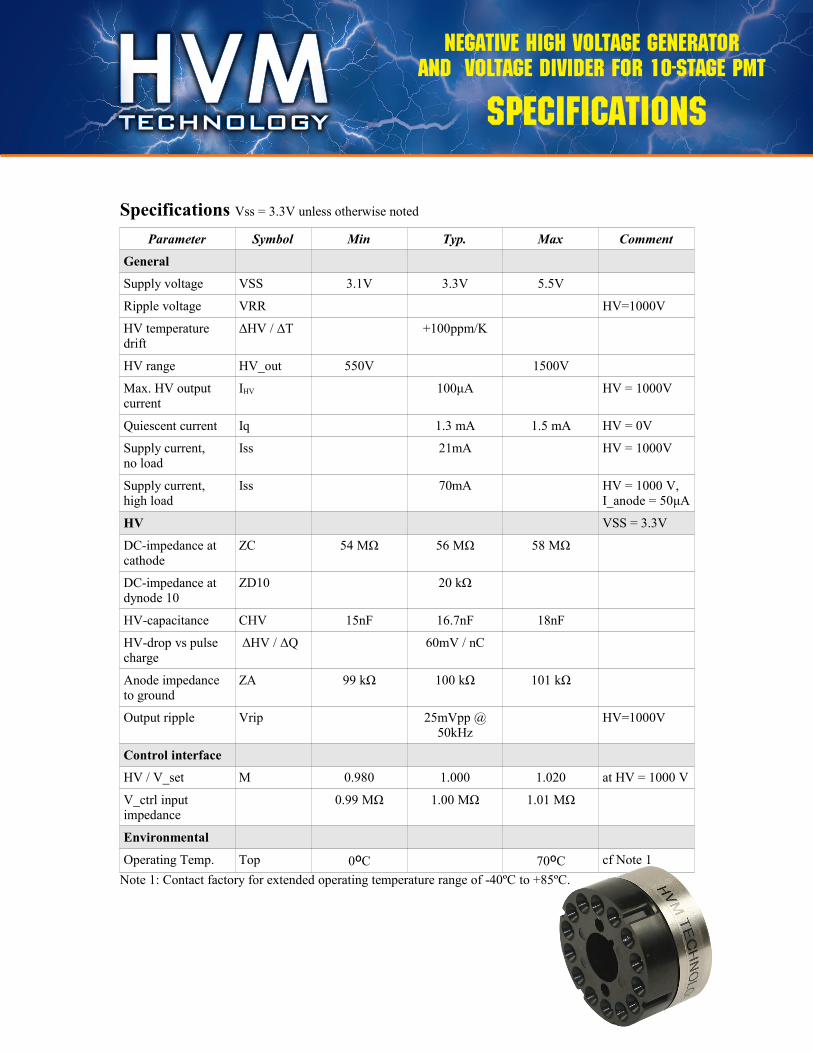
Specifications Vss = 3.3V unless otherwise noted
Parameter Symbol Min Typ. Max Comment
General
Supply voltage VSS 3.1V 3.3V 5.5V
Ripple voltage VRR HV=1000V
HV temperature drift
ΔHV / ΔT +100ppm/K
HV range HV_out 550V 1500V
Max. HV output current
IHV 100μA HV = 1000V
Quiescent current Iq 1.3 mA 1.5 mA HV = 0V
Supply current, no load
Iss 21mA HV = 1000V
Supply current, high load
Iss 70mA HV = 1000 V, I_anode = 50μA
HV VSS = 3.3V
DC-impedance at cathode
ZC 54 MΩ 56 MΩ 58 MΩ
DC-impedance at dynode 10
ZD10 20 kΩ
HV-capacitance CHV 15nF 16.7nF 18nF
HV-drop vs pulse charge
ΔHV / ΔQ 60mV / nC
Anode impedance to ground
ZA 99 kΩ 100 kΩ 101 kΩ
Output ripple Vrip 25mVpp @ 50kHz
HV=1000V
Control interface
HV / V_set M 0.980 1.000 1.020 at HV = 1000 V
V_ctrl input impedance
0.99 MΩ 1.00 MΩ 1.01 MΩ
Environmental
Operating Temp. Top 0ºC 70ºC cf Note 1
Note 1: Contact factory for extended operating temperature range of -40ºC to +85ºC.
©Bridgeport Instruments, LLC, hvBase – NegHV - B14D10 Version R1, 05/2010
Specifications hvBase-N-B14D10
Negative High Voltage Generator and Voltage Divider for 10-stage PMT
Voltage
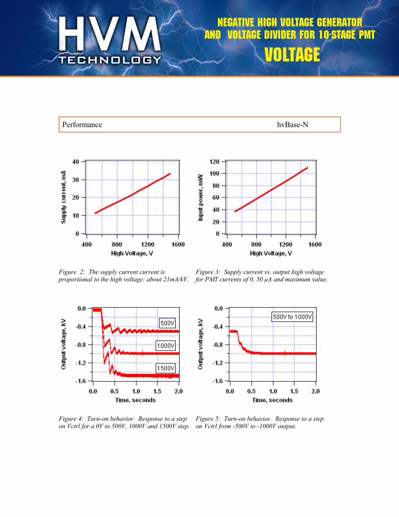
Figure 2: The supply current current is proportional to the high voltage: about 21mA/kV.
Figure 3: Supply current vs. output high voltage for PMT currents of 0, 50 μA and maximum value.
Figure 4: Turn-on behavior. Response to a step on Vctrl for a 0V to 500V, 1000V and 1500V step.
Figure 5: Turn-on behavior. Response to a step on Vctrl from -500V to -1000V output.
©Bridgeport Instruments, LLC, hvBase – NegHV - B14D10 Version R1, 05/2010
Performance hvBase-N-B14D10
Negative High Voltage Generator and Voltage Divider for 10-stage PMT
Theory
Functional Block Diagram
©Bridgeport Instruments, LLC, hvBase – NegHV - B14D10 Version R1, 05/2010
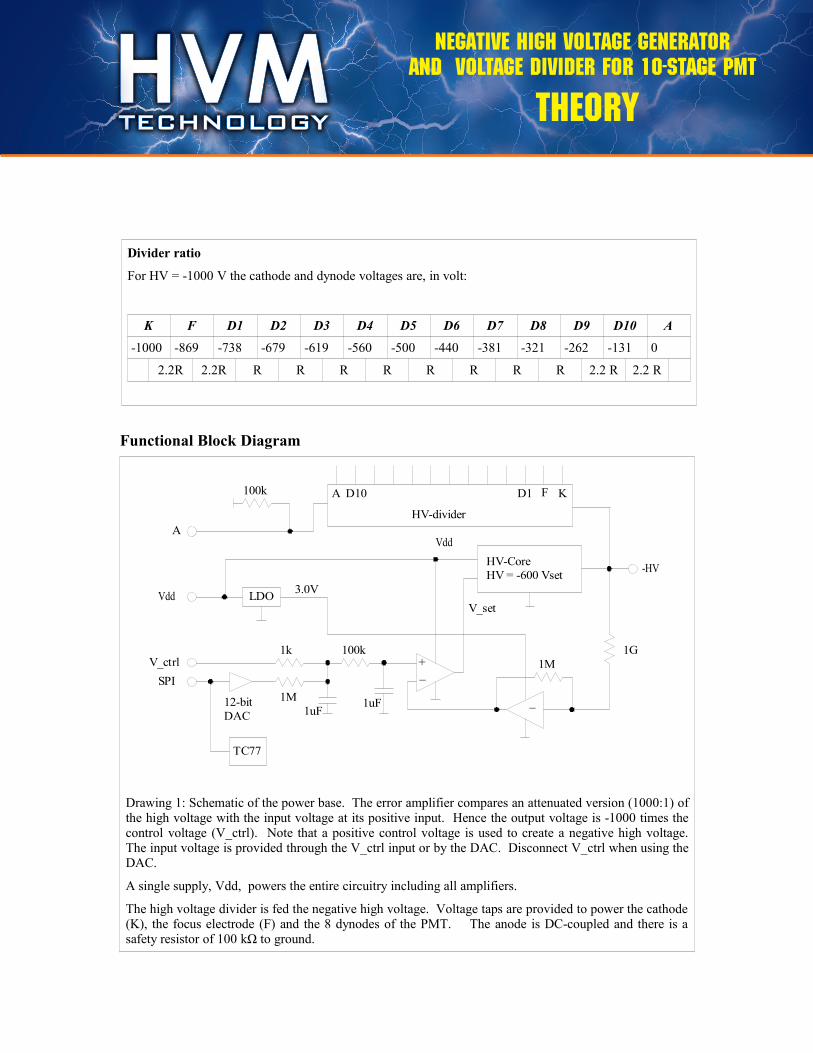
Drawing 1: Schematic of the power base. The error amplifier compares an attenuated version (1000:1) of the high voltage with the input voltage at its positive input. Hence the output voltage is -1000 times the control voltage (V_ctrl). Note that a positive control voltage is used to create a negative high voltage. The input voltage is provided through the V_ctrl input or by the DAC. Disconnect V_ctrl when using the DAC.
A single supply, Vdd, powers the entire circuitry including all amplifiers.
The high voltage divider is fed the negative high voltage. Voltage taps are provided to power the cathode (K), the focus electrode (F) and the 8 dynodes of the PMT. The anode is DC-coupled and there is a safety resistor of 100 kΩ to ground.
Divider ratio
For HV = -1000 V the cathode and dynode voltages are, in volt:
K F D1 D2 D3 D4 D5 D6 D7 D8 D9 D10 A
-1000 -869 -738 -679 -619 -560 -500 -440 -381 -321 -262 -131 0
2.2R 2.2R R R R R R R R R 2.2 R 2.2 R
hvBase-N-B14D10
+_
1k
1M
1uF12-bit
DAC
LDO
HV-Core
HV = -600 Vset
Vdd
1G
1M
-HV
100k
V_set
A
Vdd
V_ctrl
SPI
3.0V
TC77
1uF
100k
_
HV-divider
F KD1D10A
Negative High Voltage Generator and Voltage Divider for 10-stage PMT
Divider Ratio
©Bridgeport Instruments, LLC, hvBase – NegHV - B14D10 Version R1, 05/2010
Theory of Operation hvBase-N-B14D10
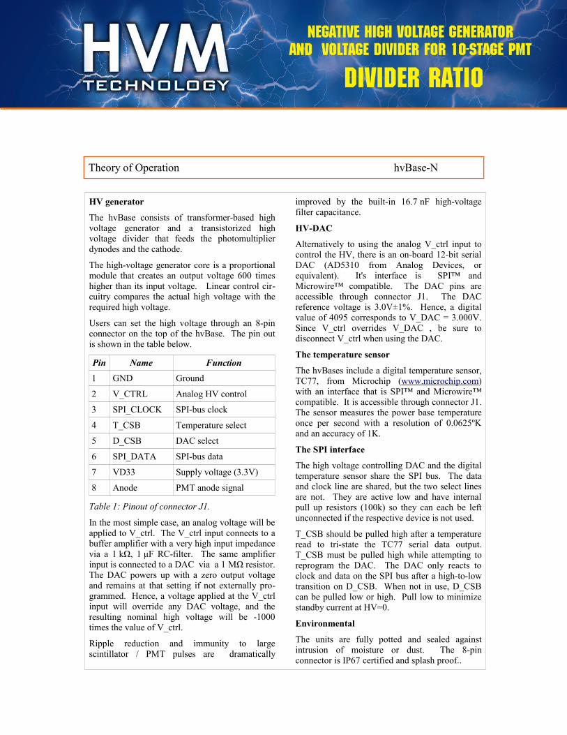
HV generator
The hvBase consists of transformer-based high voltage generator and a transistorized high voltage divider that feeds the photomultiplier dynodes and the cathode.
The high-voltage generator core is a proportional module that creates an output voltage 600 times higher than its input voltage. Linear control cir-cuitry compares the actual high voltage with the required high voltage.
Users can set the high voltage through an 8-pin connector on the top of the hvBase. The pin out is shown in the table below.
Pin Name Function
1 GND Ground
2 V_CTRL Analog HV control
3 SPI_CLOCK SPI-bus clock
4 T_CSB Temperature select
5 D_CSB DAC select
6 SPI_DATA SPI-bus data
7 VD33 Supply voltage (3.3V)
8 Anode PMT anode signal
Table 1: Pinout of connector J1.
In the most simple case, an analog voltage will be applied to V_ctrl. The V_ctrl input connects to a buffer amplifier with a very high input impedance via a 1 kΩ, 1 μF RC-filter. The same amplifier input is connected to a DAC via a 1 MΩ resistor. The DAC powers up with a zero output voltage and remains at that setting if not externally pro-grammed. Hence, a voltage applied at the V_ctrl input will override any DAC voltage, and the resulting nominal high voltage will be -1000 times the value of V_ctrl.
Ripple reduction and immunity to large scintillator / PMT pulses are dramatically
improved by the built-in 16.7 nF high-voltage filter capacitance.
HV-DAC
Alternatively to using the analog V_ctrl input to control the HV, there is an on-board 12-bit serial DAC (AD5310 from Analog Devices, or equivalent). It's interface is SPI™ and Microwire™ compatible. The DAC pins are accessible through connector J1. The DAC reference voltage is 3.0V±1%. Hence, a digital value of 4095 corresponds to V_DAC = 3.000V. Since V_ctrl overrides V_DAC , be sure to disconnect V_ctrl when using the DAC.
The temperature sensor
The hvBases include a digital temperature sensor, TC77, from Microchip (www.microchip.com) with an interface that is SPI™ and Microwire™ compatible. It is accessible through connector J1. The sensor measures the power base temperature once per second with a resolution of 0.0625ºK and an accuracy of 1K.
The SPI interface
The high voltage controlling DAC and the digital temperature sensor share the SPI bus. The data and clock line are shared, but the two select lines are not. They are active low and have internal pull up resistors (100k) so they can each be left unconnected if the respective device is not used.
T_CSB should be pulled high after a temperature read to tri-state the TC77 serial data output. T_CSB must be pulled high while attempting to reprogram the DAC. The DAC only reacts to clock and data on the SPI bus after a high-to-low transition on D_CSB. When not in use, D_CSB can be pulled low or high. Pull low to minimize standby current at HV=0.
Environmental
The units are fully potted and sealed against intrusion of moisture or dust. The 8-pin connector is IP67 certified and splash proof..
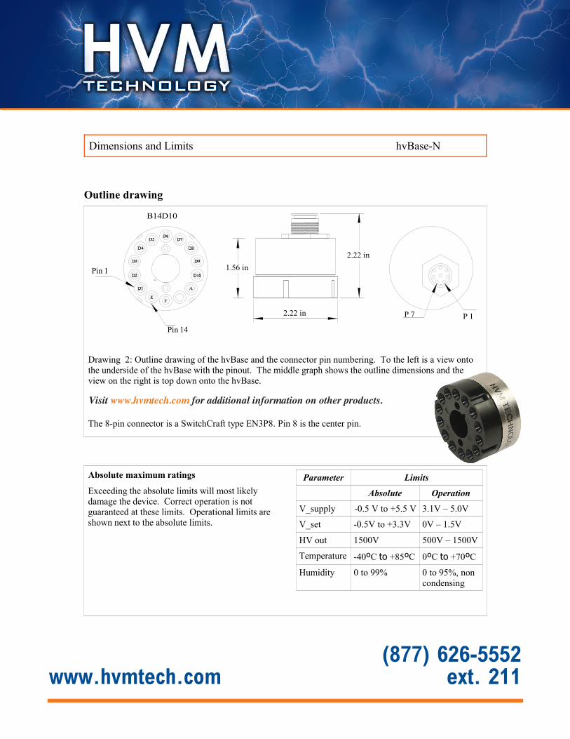
Outline drawing
©Bridgeport Instruments, LLC, hvBase – NegHV - B14D10 Version R1, 05/2010
Drawing 2: Outline drawing of the hvBase and the connector pin numbering. To the left is a view onto the underside of the hvBase with the pinout. The middle graph shows the outline dimensions and the view on the right is top down onto the hvBase.
The PMT socket is an HDW-1014A from Bridgeport Instrumentshttp://www.bridgeportinstruments.com/products/hdw1014a/hdw1014a.html
The 8-pin connector is a SwitchCraft type EN3P8. Pin 8 is the center pin.
Dimensions and Limits hvBase-N-B14D10
Absolute maximum ratings
Exceeding the absolute limits will most likely damage the device. Correct operation is not guaranteed at these limits. Operational limits are shown next to the absolute limits.
Parameter Limits
Absolute Operation
V_supply -0.5 V to +5.5 V 3.1V – 5.0V
V_set -0.5V to +3.3V 0V – 1.5V
HV out 1500V 500V – 1500V
Temperature -40ºC to +85ºC 0ºC to +70ºC
Humidity 0 to 99% 0 to 95%, non condensing
2.22 in
2.22 in
1.56 in
B14D10
Pin 14
Pin 1
P 1P 7
(877) 626-5552 ext. 211www.hvmtech.com
Visit www.hvmtech.com for additional information on other products.
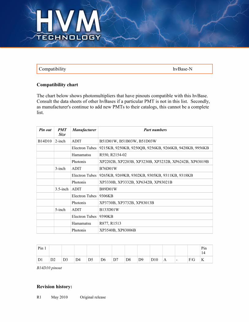
Compatibility chart
The chart below shows photomultipliers that have pinouts compatible with this hvBase.
Consult the data sheets of other hvBases if a particular PMT is not in this list. Secondly,
as manufacturer's continue to add new PMTs to their catalogs, this cannot be a complete
list.
Pin out PMTSize
Manufacturer Part numbers
B14D10 2-inch ADIT B51D01W, B51B03W, B51D03W
Electron Tubes 9215KB, 9250KB, 9250QB, 9256KB, 9266KB, 9428KB, 9956KB
Hamamatsu R550, R2154-02
Photonis XP2202B, XP2203B, XP3230B, XP3232B, XP6242B, XP83019B
3-inch ADIT B76D01W
Electron Tubes 9265KB, 9269KB, 9302KB, 9305KB, 9311KB, 9318KB
Photonis XP3330B, XP3332B, XP6342B, XP83021B
3.5-inch ADIT B89D01W
Electron Tubes 9306KB
Photonis XP3730B, XP3732B, XP83013B
5-inch ADIT B133D01W
Electron Tubes 9390KB
Hamamatsu R877, R1513
Photonis XP3540B, XP83006B
Pin 1 Pin 14
D1 D2 D3 D4 D5 D6 D7 D8 D9 D10 A - F/G K
B14D10 pinout
Revision history:
R1 May 2010 Original release
©Bridgeport Instruments, LLC, hvBase – NegHV - B14D10 Version R1, 05/2010
Compatibility hvBase-N-B14D10