Embed Size (px)
Citation preview
E-M-HF8-V2_13 Rotronic AG Bassersdorf, Switzerland
Document code Unit
HygroFlex HF8 Humidity Temperature Transmitter: User Guide
Instruction Manual
Document Type
Page 1 of 37 Document title
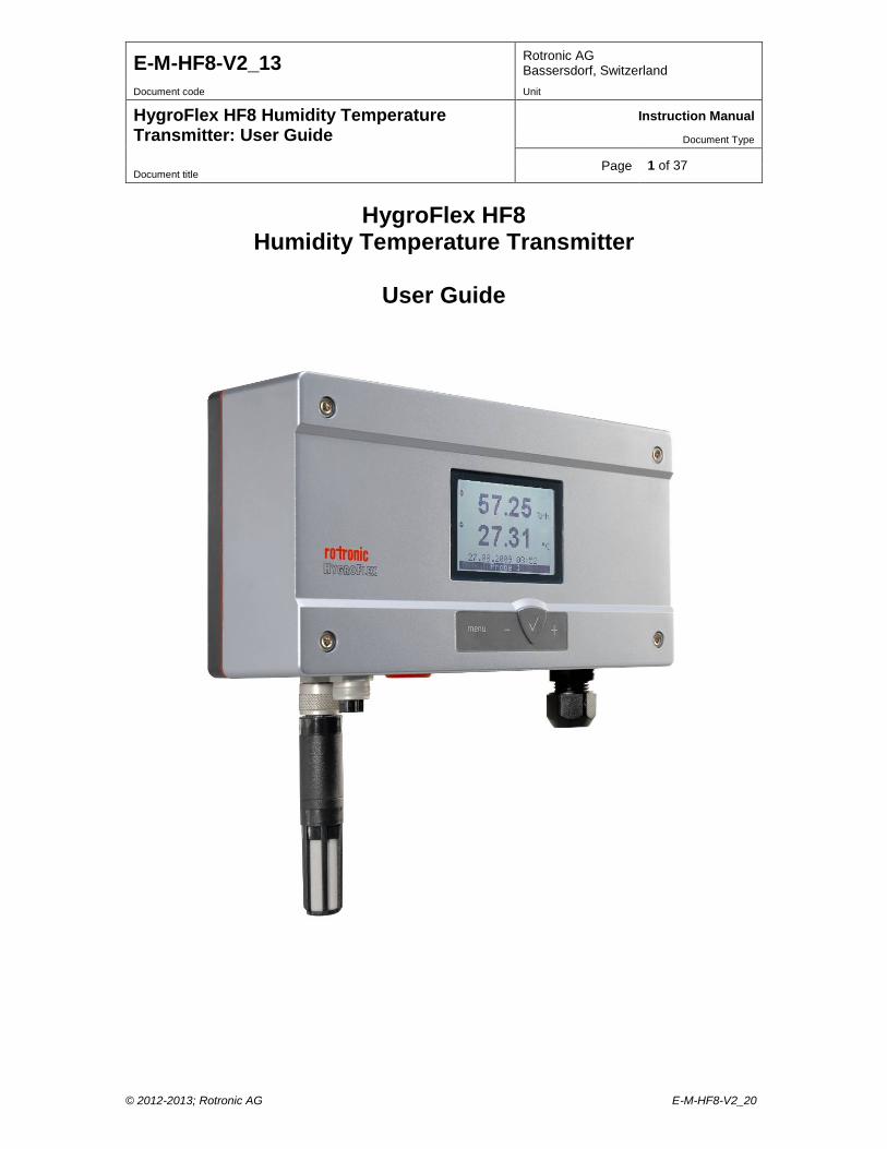
HygroFlex HF8
Humidity Temperature Transmitter
User Guide
© 2012-2013; Rotronic AG E-M-HF8-V2_20
E-M-HF8-V2_13 Rotronic AG Bassersdorf, Switzerland
Document code Unit
HygroFlex HF8 Humidity Temperature Transmitter: User Guide
Instruction Manual
Document Type
Page 2 of 37 Document title
Table of contents
1 Overview .............................................................................................................................................. 3 2 Dimensional drawings ........................................................................................................................ 4 3 General description ............................................................................................................................. 4 3.1 Power supply options ....................................................................................................................... 4 3.2 Probe inputs ..................................................................................................................................... 5 3.3 Measured parameters ...................................................................................................................... 6 3.4 Calculated psychrometric parameters .............................................................................................. 6 3.5 Custom Calculations ......................................................................................................................... 6 3.6 Real time clock ................................................................................................................................. 7 3.7 Data logging function ........................................................................................................................ 7 3.8 Analog outputs, relay contacts and digital interface options ............................................................. 7 3.9 Optional display and keypad............................................................................................................. 8 3.10 Audible alarm (beeper) ..................................................................................................................... 9 3.11 Service connector ............................................................................................................................. 9 3.12 Protection grade of models with Ethernet interface .......................................................................... 9 3.13 HW4 Software compatibility ............................................................................................................ 10 4 User configurable settings and functions ....................................................................................... 10 4.1 Function overview (HF8 and HygroClip 2 probe) ............................................................................ 10 4.2 Interaction between the HF8 and HygroClip 2 probe functions ...................................................... 11 4.3 Configuration of the analog output signal type ............................................................................... 12 5 Mechanical installation ..................................................................................................................... 12 5.1 General guidelines .......................................................................................................................... 12 5.2 HF8 enclosure ................................................................................................................................ 13 5.3 Installation of the enclosure and probe ........................................................................................... 13 6 Electrical installation ........................................................................................................................ 14 6.1 General wiring guidelines ............................................................................................................... 14 6.2 Guidelines for RS-485 wiring .......................................................................................................... 15 6.3 Cable grip and cable specifications ................................................................................................ 15 6.4 Wiring ............................................................................................................................................. 15 7 Operation ........................................................................................................................................... 21 7.1 Analog outputs ................................................................................................................................ 21 7.2 Digital interface ............................................................................................................................... 21 7.3 Optional display and keypad........................................................................................................... 23 7.4 Frequently used settings ................................................................................................................ 27 7.5 Data logging function ...................................................................................................................... 28 7.6 Relay contacts ................................................................................................................................ 29 7.7 Audible alarm (beeper) ................................................................................................................... 29 8 Maintenance....................................................................................................................................... 29 8.1 Service cable .................................................................................................................................. 29 8.2 Location of the service connector (mini USB type) ......................................................................... 29 8.3 Periodic calibration check of the HygroClip 2 probe ....................................................................... 30 8.4 HF8 probe calibration and adjustment procedures ......................................................................... 30 8.5 Cleaning or replacing the probe dust filter ...................................................................................... 32 8.6 Validation of the output signals transmission .................................................................................. 32 9 Firmware updates .............................................................................................................................. 32 10 Technical data ................................................................................................................................... 33 10.1 Specifications ................................................................................................................................. 33 10.2 Dew point accuracy ........................................................................................................................ 35 11 Accessories ....................................................................................................................................... 35 12 Supporting documents ..................................................................................................................... 36 13 Document releases ........................................................................................................................... 37
© 2012-2013; Rotronic AG E-M-HF8-V2_20
E-M-HF8-V2_13 Rotronic AG Bassersdorf, Switzerland
Document code Unit
HygroFlex HF8 Humidity Temperature Transmitter: User Guide
Instruction Manual
Document Type
Page 3 of 37 Document title
Applicability: This manual applies to all instruments of the HygroFlex HF8 series with firmware version 2.x, where 2.x can be 2.0, 2.1, etc. Changes to the last digit of the version number reflect minor firmware changes that do not affect the manner in which the instrument should be operated. Software compatibility warning The HF8 with firmware version 2.x is designed for use with the ROTRONIC HW4 software version 3.2.0 or higher. Do not try to configure the HF8 with any version of the ROTRONIC HW4 software lower than 2.4.0 as this will damage the HF8 firmware and prevent normal operation of the transmitter.
1 Overview The HygroFlex HF8 transmitter series is designed for fixed installation in applications where high measurement accuracy is required. The HF8 has two probe inputs which can be individually configured for use with a HygroClip 2 plug-in probe or with a 1-channel analog probe. The wide assortment of HygroClip 2 humidity-temperature probes can meet almost any application requirement. The HygroClip 2 probes feature well proven, durable sensors. Digital signal processing within the probe ensures consistent product performance and also facilitates the task of field maintenance with features such as potentiometer free – digital calibration, hot-swapping of the probe, etc. Depending on the HygroClip 2 probe model, the HF8 can measure conditions within the range of 0 to 100 %RH and -100 to 200°C (-148 to 392°F). The HF8 can be configured to calculate a parameter as dew point, enthalpy, mixing ratio, etc. The HF8 can be ordered for different types of supply voltage, including DC voltage with galvanic separation and is available with several combinations of analog output signals (up to 4), digital interface (RS-485, Ethernet) and relay contacts (up to 4). Based on the ROTRONIC AirChip 3000 digital technology the HF8 series and HygroClip 2 probes offer the following user functions: • User configurable settings • Calculation of psychrometric parameters such as the dew or frost point • Custom Calculations (user defined) such as the difference between dew point and temperature • Humidity temperature calibration and adjustment • Simulator mode • Automatic humidity sensor test and drift compensation • Sensor failure mode • Data logging The HF8 has an internal real time clock and can be used to record up to 10,000 pairs of relative humidity and temperature values provided by a single HygroClip 2 probe or up to 10,000 data values provided by a single 1-channel analog probe. Data logging by the HF8 adds another layer of data protection when the HF8 is connected to network. The ability for the user to easily update both the HF8 and HygroClip 2 probe firmware means that instruments of the HF8 series can be kept up-to-date regarding any future functionality improvement.
© 2012-2013; Rotronic AG E-M-HF8-V2_20
E-M-HF8-V2_13 Rotronic AG Bassersdorf, Switzerland
Document code Unit
HygroFlex HF8 Humidity Temperature Transmitter: User Guide
Instruction Manual
Document Type
Page 4 of 37 Document title
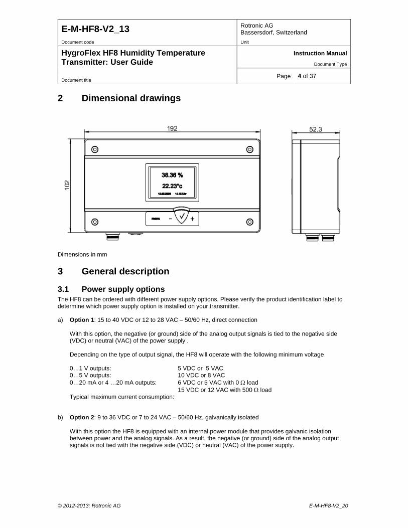
2 Dimensional drawings
Dimensions in mm
3 General description
3.1 Power supply options The HF8 can be ordered with different power supply options. Please verify the product identification label to determine which power supply option is installed on your transmitter. a) Option 1: 15 to 40 VDC or 12 to 28 VAC – 50/60 Hz, direct connection
With this option, the negative (or ground) side of the analog output signals is tied to the negative side (VDC) or neutral (VAC) of the power supply . Depending on the type of output signal, the HF8 will operate with the following minimum voltage 0…1 V outputs: 5 VDC or 5 VAC 0…5 V outputs: 10 VDC or 8 VAC 0…20 mA or 4 …20 mA outputs: 6 VDC or 5 VAC with 0 Ω load 15 VDC or 12 VAC with 500 Ω load Typical maximum current consumption:
b) Option 2: 9 to 36 VDC or 7 to 24 VAC – 50/60 Hz, galvanically isolated With this option the HF8 is equipped with an internal power module that provides galvanic isolation between power and the analog signals. As a result, the negative (or ground) side of the analog output signals is not tied with the negative side (VDC) or neutral (VAC) of the power supply.
© 2012-2013; Rotronic AG E-M-HF8-V2_20
E-M-HF8-V2_13 Rotronic AG Bassersdorf, Switzerland
Document code Unit
HygroFlex HF8 Humidity Temperature Transmitter: User Guide
Instruction Manual
Document Type
Page 5 of 37 Document title
c) Option 3: 85 to 265 VAC, 5 Watt, 50-60 Hz, galvanically isolated
As with option 2, the HF8 is equipped with an internal power module that provides galvanic isolation between power and the analog signals. As a result, the negative (or ground) side of the analog output signals is not tied with the negative side (VDC) or neutral (VAC) of the power supply.
d) Option 4: power over a RS-485 network
With the exception of models with any of the galvanically isolated power supply options, the HF8 with RS-485 interface can be directly powered from the main RS-485 data line. In that case the power terminals of the HF8 should not be connected.
See Technical Data > Specifications for the typical current consumption of the HF8
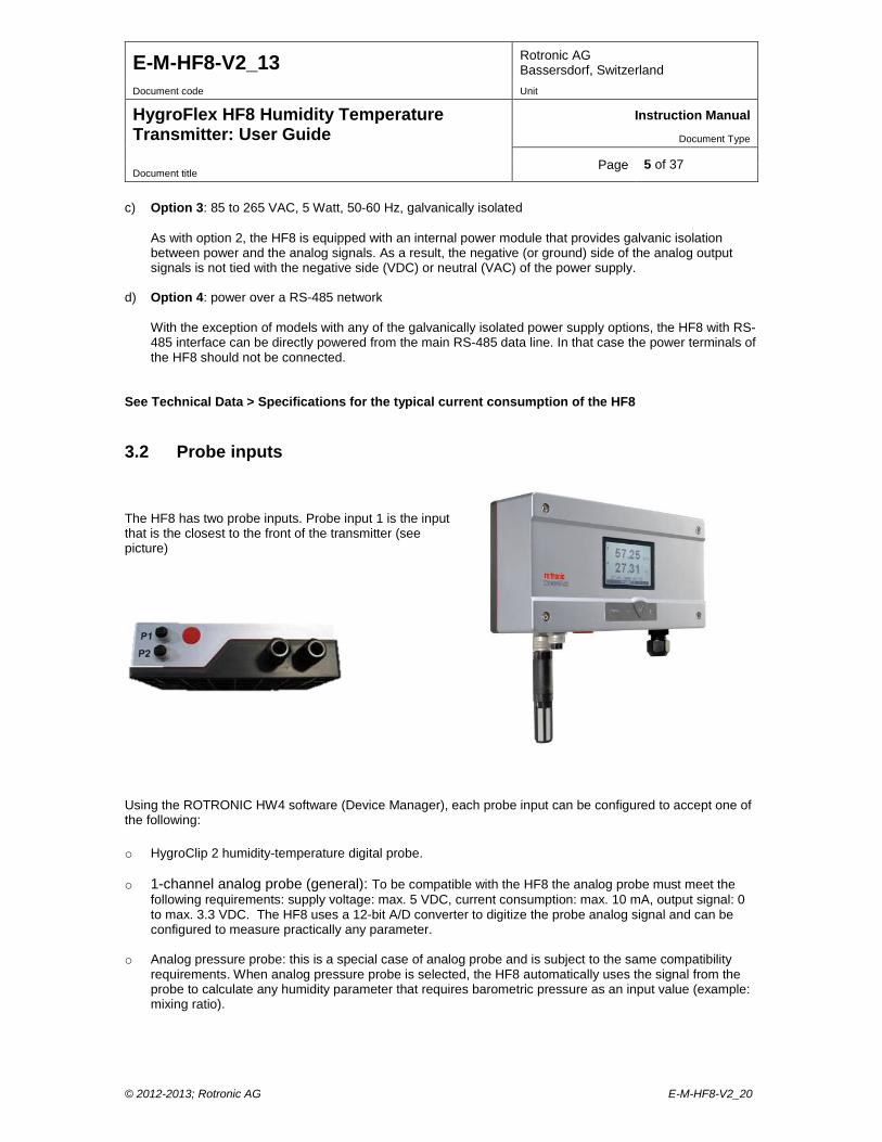
3.2 Probe inputs The HF8 has two probe inputs. Probe input 1 is the input that is the closest to the front of the transmitter (see picture)
Using the ROTRONIC HW4 software (Device Manager), each probe input can be configured to accept one of the following: o HygroClip 2 humidity-temperature digital probe.
o 1-channel analog probe (general): To be compatible with the HF8 the analog probe must meet the
following requirements: supply voltage: max. 5 VDC, current consumption: max. 10 mA, output signal: 0 to max. 3.3 VDC. The HF8 uses a 12-bit A/D converter to digitize the probe analog signal and can be configured to measure practically any parameter.
o Analog pressure probe: this is a special case of analog probe and is subject to the same compatibility requirements. When analog pressure probe is selected, the HF8 automatically uses the signal from the probe to calculate any humidity parameter that requires barometric pressure as an input value (example: mixing ratio).
© 2012-2013; Rotronic AG E-M-HF8-V2_20
E-M-HF8-V2_13 Rotronic AG Bassersdorf, Switzerland
Document code Unit
HygroFlex HF8 Humidity Temperature Transmitter: User Guide
Instruction Manual
Document Type
Page 6 of 37 Document title
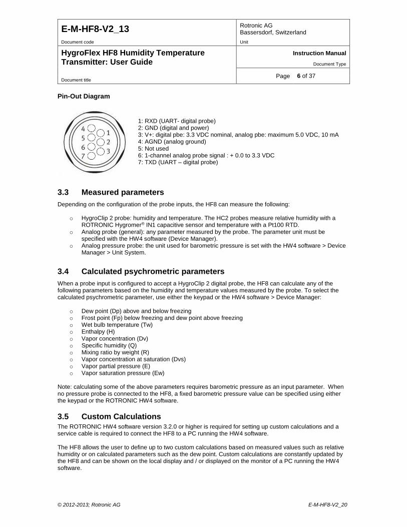
Pin-Out Diagram
3.3 Measured parameters Depending on the configuration of the probe inputs, the HF8 can measure the following:
o HygroClip 2 probe: humidity and temperature. The HC2 probes measure relative humidity with a ROTRONIC Hygromer® IN1 capacitive sensor and temperature with a Pt100 RTD.
o Analog probe (general): any parameter measured by the probe. The parameter unit must be specified with the HW4 software (Device Manager).
o Analog pressure probe: the unit used for barometric pressure is set with the HW4 software > Device Manager > Unit System.
3.4 Calculated psychrometric parameters When a probe input is configured to accept a HygroClip 2 digital probe, the HF8 can calculate any of the following parameters based on the humidity and temperature values measured by the probe. To select the calculated psychrometric parameter, use either the keypad or the HW4 software > Device Manager:
o Dew point (Dp) above and below freezing o Frost point (Fp) below freezing and dew point above freezing o Wet bulb temperature (Tw) o Enthalpy (H) o Vapor concentration (Dv) o Specific humidity (Q) o Mixing ratio by weight (R) o Vapor concentration at saturation (Dvs) o Vapor partial pressure (E) o Vapor saturation pressure (Ew)
Note: calculating some of the above parameters requires barometric pressure as an input parameter. When no pressure probe is connected to the HF8, a fixed barometric pressure value can be specified using either the keypad or the ROTRONIC HW4 software.
3.5 Custom Calculations The ROTRONIC HW4 software version 3.2.0 or higher is required for setting up custom calculations and a service cable is required to connect the HF8 to a PC running the HW4 software. The HF8 allows the user to define up to two custom calculations based on measured values such as relative humidity or on calculated parameters such as the dew point. Custom calculations are constantly updated by the HF8 and can be shown on the local display and / or displayed on the monitor of a PC running the HW4 software.
1: RXD (UART- digital probe) 2: GND (digital and power) 3: V+: digital pbe: 3.3 VDC nominal, analog pbe: maximum 5.0 VDC, 10 mA 4: AGND (analog ground) 5: Not used 6: 1-channel analog probe signal : + 0.0 to 3.3 VDC 7: TXD (UART – digital probe)
© 2012-2013; Rotronic AG E-M-HF8-V2_20
E-M-HF8-V2_13 Rotronic AG Bassersdorf, Switzerland
Document code Unit
HygroFlex HF8 Humidity Temperature Transmitter: User Guide
Instruction Manual
Document Type
Page 7 of 37 Document title
A custom calculation can be associated with any of the HF8 inputs. When associated with an input, the custom calculation can in turn be associated with any of the HF8 analog outputs. The user can also define low and high limits for a custom calculation and use these limits to generate an alarm and/or energize a relay. Examples: o Difference between the humidity measured by probe 1 and probe 2 o Difference between the temperature measured by probe 1 and probe 2 o Difference between temperature measured by probe 1 and the dew or frost point calculated by probe 2 o Average of the humidity measured by probe 1 and probe 2 o Average of the temperature measured by probe 1 and probe 2 Instructions regarding custom calculations are provided in the following HW4 manual: E-M-HW4v3-F2-015, HW4 software version 3: Device Manager – HF8 transmitter.
3.6 Real time clock The HF8 clock keeps track of the date and time and can be adjusted from the keypad. Using the HW4 software, the clock can be synchronized with the PC date and time. The clock does not automatically adjust for daylight saving time (DST).
3.7 Data logging function The HF8 can log up to 10,000 pairs of relative humidity and temperature values provided by a single HygroClip 2 probe or up to 10,000 data values provided by a single 1-channel analog probe. Both probe inputs can be logged at the same time and in that case the recording capacity per probe is cut in half. Each record is automatically date and time stamped. The calculated parameter cannot be recorded.
3.8 Analog outputs, relay contacts and digital interface options The HF8 can be ordered with any of the following combinations of analog outputs, relay contacts and digital interface:
o 4 analog output signals + 4 relay contacts (no digital interface). o 4 analog output signals + 4 relay contacts + RS-485 o 4 analog output signals + 2 relay contacts + RS-485 + Ethernet (wired) o Ethernet with PoE (complies with standard IEEE 802.3af)
Note: models with a RS-485 interface can be powered from a central voltage source (15…40 VDC) via the RS-485 main data cable. In that case the HF8 should not be powered from any other source.
3.8.1 Analog output signals All 4 analog outputs of the HF8 provide the same type of signal: 0…20 mA or 4…20 mA or 0…1V or 0…5V or 0…10V. The type of analog signal can be selected globally for all outputs after connecting the HF8 service connector to a PC running the ROTRONIC HW4 software. No adjustment is required after changing the type of output signal. Using the HW4 software, each analog output can be associated with any of the two HF8 probe inputs and can be made to correspond to one of the following:
o Relative humidity or parameter measured by an analog 1-channel probe o Temperature o Calculated parameter, including a Custom Calculation (if enabled)
The scale of each analog output can be set within the numerical limits of -999.99 and 9999.99. The D/A converters used to generate the analog output signals feature a 16-bit resolution.
© 2012-2013; Rotronic AG E-M-HF8-V2_20
E-M-HF8-V2_13 Rotronic AG Bassersdorf, Switzerland
Document code Unit
HygroFlex HF8 Humidity Temperature Transmitter: User Guide
Instruction Manual
Document Type
Page 8 of 37 Document title
3.8.2 RS-485 serial interface The RS-485 interface can be used to connect together up to 64 devices in a multi-dropped arrangement. In principle, an unlimited number of such networks can be monitored with the HW4 software, but each RS-485 multi-drop network is limited to 64 devices. A master device is required to connect a RS-485 network to a PC, such as for example:
o HF8 transmitter with both an Ethernet and a RS-485 port. o Cable AC3010 (master substitute) with USB and RS-485 ports.
RS-485 Compatibility: The HF8 uses the RO-ASCII communications protocol. This protocol is not compatible with the protocol used by the previous generation of ROTRONIC instruments and by the HygroLog HL-NT data logger. Do not connect legacy products or the HL-NT data logger to the same RS-485 multi-drop network as the HF8 transmitter.
3.8.3 Relay contacts The HF8 is available with up to 4 relay contacts (SPDT: single pole double throw). Connection to a PC running the ROTRONIC HW4 software is required to configure each relay contact. Each relay contact can be associated with any of the two HF8 probe inputs and can be made to monitor alarm conditions associated with one of the following:
o Relative humidity or parameter measured by an analog 1-channel probe o Temperature o Calculated parameter, including a Custom Calculation (if enabled)
A relay output is energized when the value of the parameter being monitored corresponds to a user defined out-of-limits value. High and low limits for the measured and calculated parameters can be defined for each individual probe input with the HW4 software Device Manager (see E-M-HW4v3-F2-015). The HW4 software is also used to configure the operating parameters of each relay such as time delay to energize or de-energize the relay, latching or non-latching operation and can also be used to limit operation of the relays to a time schedule.
3.9 Optional display and keypad
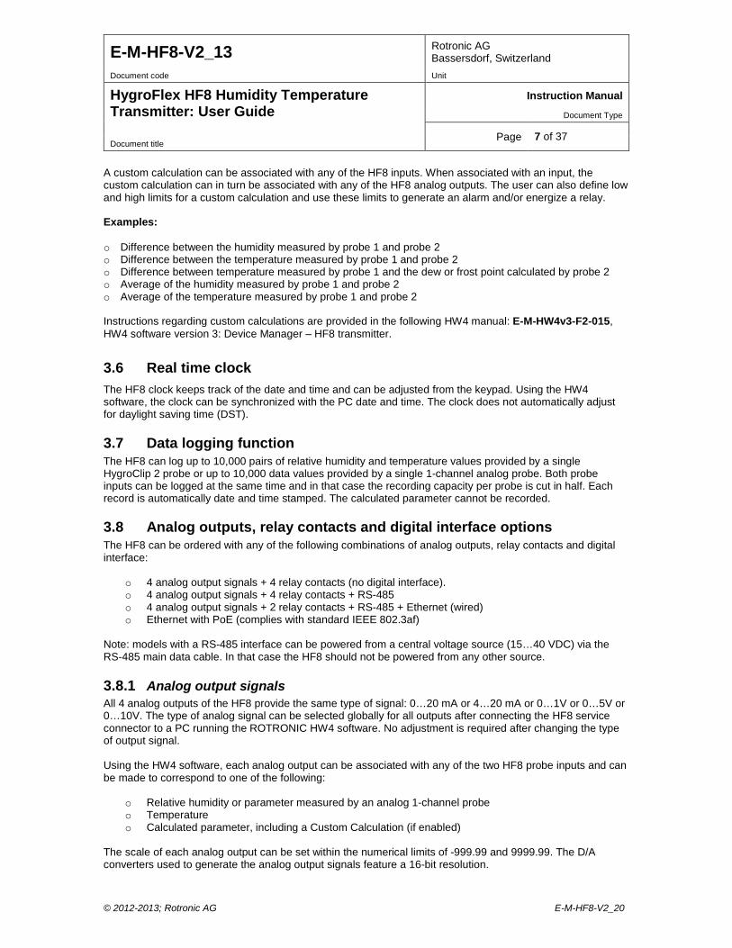
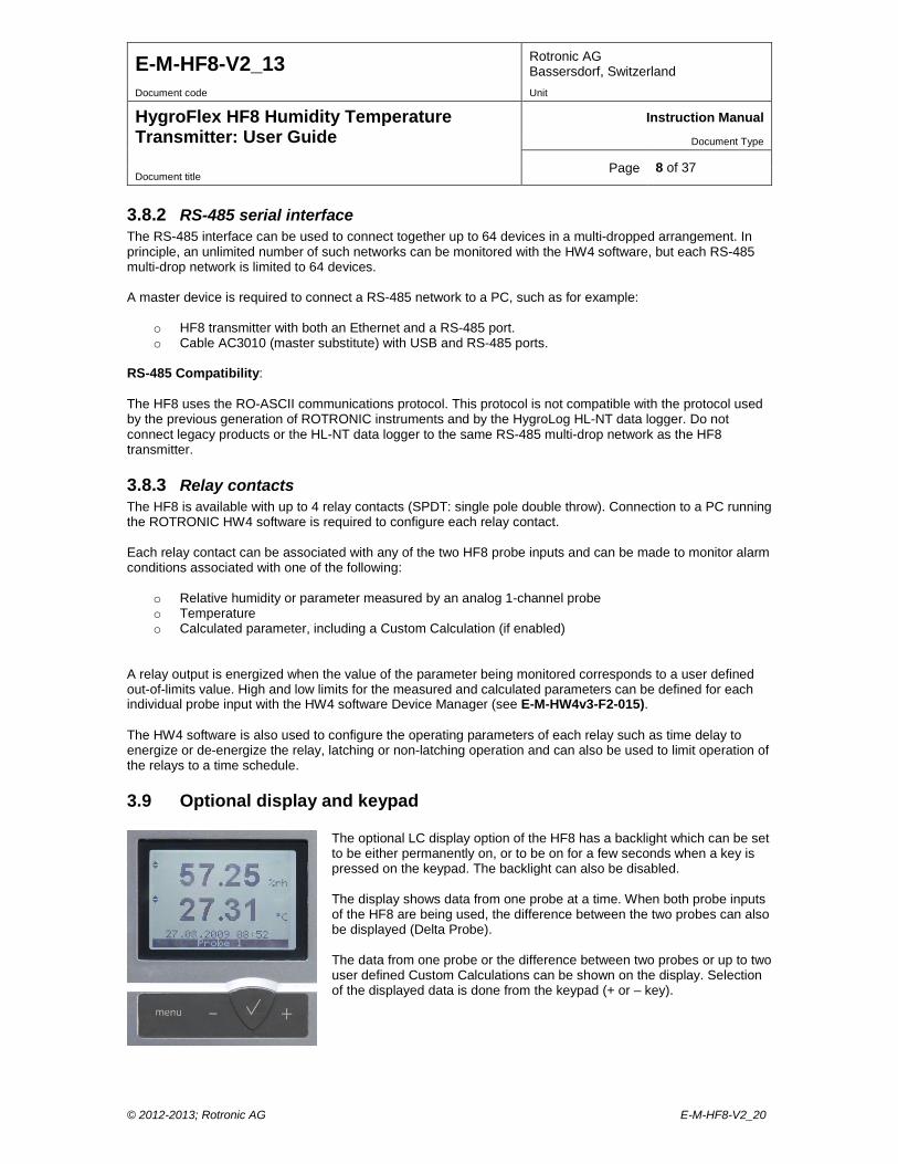
The optional LC display option of the HF8 has a backlight which can be set to be either permanently on, or to be on for a few seconds when a key is pressed on the keypad. The backlight can also be disabled. The display shows data from one probe at a time. When both probe inputs of the HF8 are being used, the difference between the two probes can also be displayed (Delta Probe). The data from one probe or the difference between two probes or up to two user defined Custom Calculations can be shown on the display. Selection of the displayed data is done from the keypad (+ or – key).
© 2012-2013; Rotronic AG E-M-HF8-V2_20
E-M-HF8-V2_13 Rotronic AG Bassersdorf, Switzerland
Document code Unit
HygroFlex HF8 Humidity Temperature Transmitter: User Guide
Instruction Manual
Document Type
Page 9 of 37 Document title
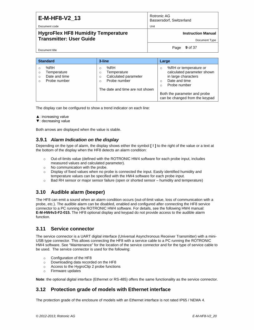
Standard 3-line Large
o %RH o Temperature o Date and time o Probe number
o %RH o Temperature o Calculated parameter o Probe number The date and time are not shown
o %RH or temperature or calculated parameter shown in large characters
o Date and time o Probe number Both the parameter and probe can be changed from the keypad
The display can be configured to show a trend indicator on each line: : increasing value : decreasing value Both arrows are displayed when the value is stable.
3.9.1 Alarm Indication on the display Depending on the type of alarm, the display shows either the symbol [ ! ] to the right of the value or a text at the bottom of the display when the HF8 detects an alarm condition:
o Out-of-limits value (defined with the ROTRONIC HW4 software for each probe input, includes measured values and calculated parameter).
o No communication with the probe. o Display of fixed values when no probe is connected the input. Easily identified humidity and
temperature values can be specified with the HW4 software for each probe input. o Bad RH sensor or major sensor failure (open or shorted sensor – humidity and temperature)
3.10 Audible alarm (beeper) The HF8 can emit a sound when an alarm condition occurs (out-of-limit value, loss of communication with a probe, etc.). The audible alarm can be disabled, enabled and configured after connecting the HF8 service connector to a PC running the ROTRONIC HW4 software. For details, see the following HW4 manual: E-M-HW4v3-F2-015. The HF8 optional display and keypad do not provide access to the audible alarm function.
3.11 Service connector The service connector is a UART digital interface (Universal Asynchronous Receiver Transmitter) with a mini-USB type connector. This allows connecting the HF8 with a service cable to a PC running the ROTRONIC HW4 software. See “Maintenance” for the location of the service connector and for the type of service cable to be used. The service connector is used for the following:
o Configuration of the HF8 o Downloading data recorded on the HF8 o Access to the HygroClip 2 probe functions o Firmware updates
Note: the optional digital interface (Ethernet or RS-485) offers the same functionality as the service connector.
3.12 Protection grade of models with Ethernet interface The protection grade of the enclosure of models with an Ethernet interface is not rated IP65 / NEMA 4.
© 2012-2013; Rotronic AG E-M-HF8-V2_20
E-M-HF8-V2_13 Rotronic AG Bassersdorf, Switzerland
Document code Unit
HygroFlex HF8 Humidity Temperature Transmitter: User Guide
Instruction Manual
Document Type
Page 10 of 37 Document title
3.13 HW4 Software compatibility The HF8 is best used with HW4 version 3.2.0 or higher. WARNING: do not use the HF8 with any HW4 version lower than 2.4.0 as this could damage the HF8 firmware and prevent normal operation.
4 User configurable settings and functions The HF8 can be used just as any conventional humidity and temperature transmitter. Making use of the HF8 configurable settings and functions is entirely up to the user and the appropriate settings depend on the user application. We have provided below a short description of the HF8 functions and also indicated the factory default settings.
4.1 Function overview (HF8 and HygroClip 2 probe)
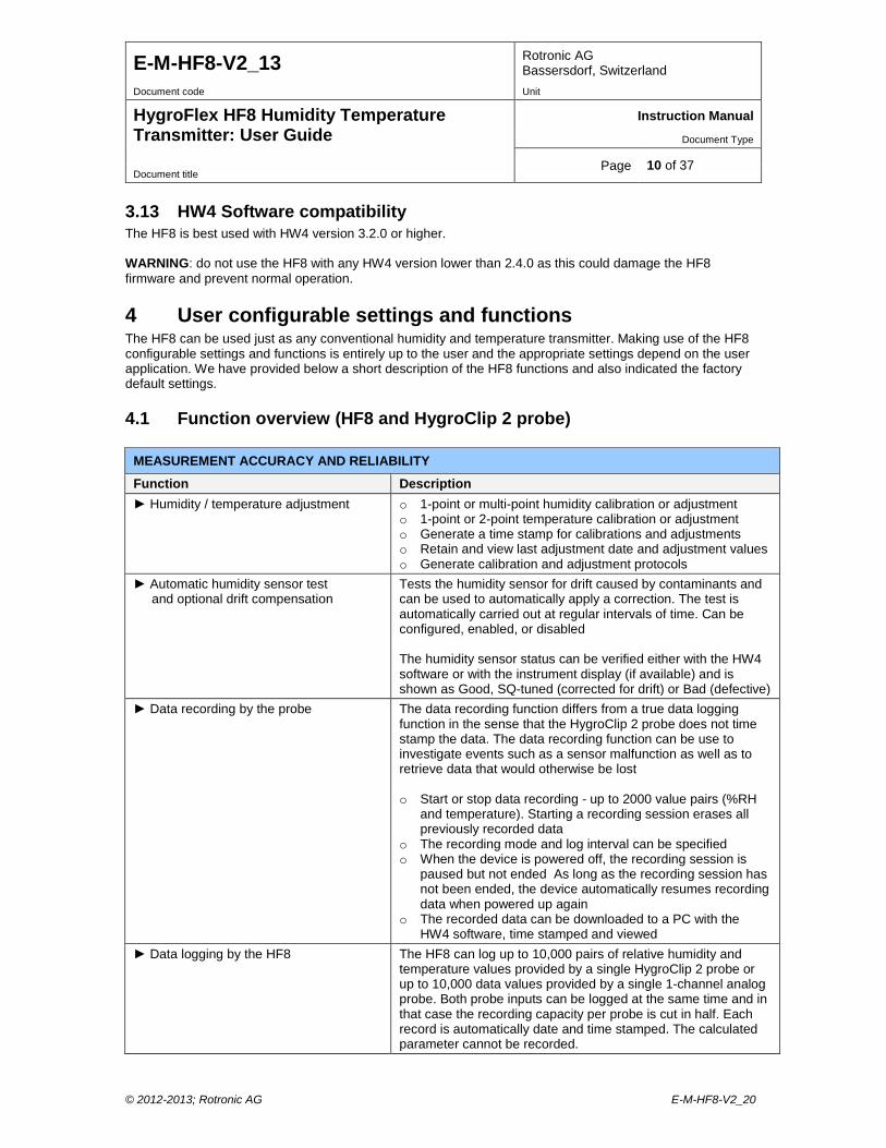
MEASUREMENT ACCURACY AND RELIABILITY
Function Description Humidity / temperature adjustment o 1-point or multi-point humidity calibration or adjustment
o 1-point or 2-point temperature calibration or adjustment o Generate a time stamp for calibrations and adjustments o Retain and view last adjustment date and adjustment values o Generate calibration and adjustment protocols
Automatic humidity sensor test and optional drift compensation
Tests the humidity sensor for drift caused by contaminants and can be used to automatically apply a correction. The test is automatically carried out at regular intervals of time. Can be configured, enabled, or disabled The humidity sensor status can be verified either with the HW4 software or with the instrument display (if available) and is shown as Good, SQ-tuned (corrected for drift) or Bad (defective)
Data recording by the probe The data recording function differs from a true data logging function in the sense that the HygroClip 2 probe does not time stamp the data. The data recording function can be use to investigate events such as a sensor malfunction as well as to retrieve data that would otherwise be lost o Start or stop data recording - up to 2000 value pairs (%RH
and temperature). Starting a recording session erases all previously recorded data
o The recording mode and log interval can be specified o When the device is powered off, the recording session is
paused but not ended As long as the recording session has not been ended, the device automatically resumes recording data when powered up again
o The recorded data can be downloaded to a PC with the HW4 software, time stamped and viewed
Data logging by the HF8 The HF8 can log up to 10,000 pairs of relative humidity and temperature values provided by a single HygroClip 2 probe or up to 10,000 data values provided by a single 1-channel analog probe. Both probe inputs can be logged at the same time and in that case the recording capacity per probe is cut in half. Each record is automatically date and time stamped. The calculated parameter cannot be recorded.
© 2012-2013; Rotronic AG E-M-HF8-V2_20
E-M-HF8-V2_13 Rotronic AG Bassersdorf, Switzerland
Document code Unit
HygroFlex HF8 Humidity Temperature Transmitter: User Guide
Instruction Manual
Document Type
Page 11 of 37 Document title
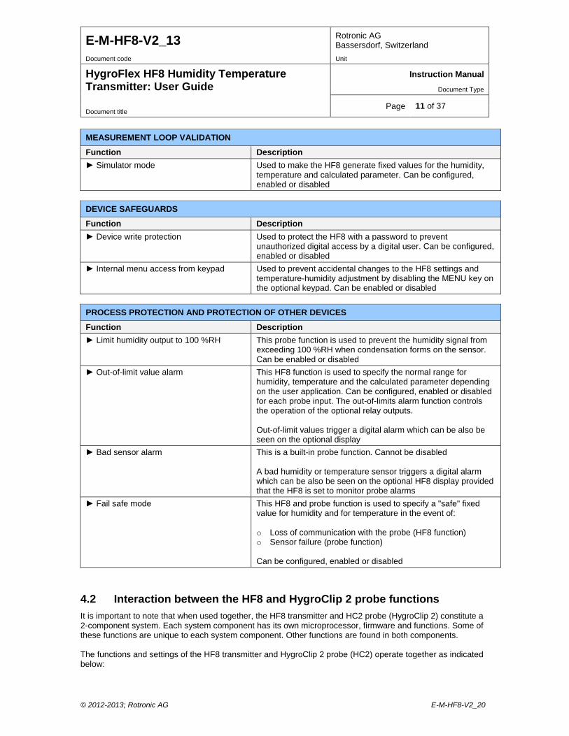
MEASUREMENT LOOP VALIDATION
Function Description Simulator mode Used to make the HF8 generate fixed values for the humidity,
temperature and calculated parameter. Can be configured, enabled or disabled
DEVICE SAFEGUARDS
Function Description Device write protection Used to protect the HF8 with a password to prevent
unauthorized digital access by a digital user. Can be configured, enabled or disabled
Internal menu access from keypad Used to prevent accidental changes to the HF8 settings and temperature-humidity adjustment by disabling the MENU key on the optional keypad. Can be enabled or disabled
PROCESS PROTECTION AND PROTECTION OF OTHER DEVICES
Function Description Limit humidity output to 100 %RH This probe function is used to prevent the humidity signal from
exceeding 100 %RH when condensation forms on the sensor. Can be enabled or disabled
Out-of-limit value alarm This HF8 function is used to specify the normal range for humidity, temperature and the calculated parameter depending on the user application. Can be configured, enabled or disabled for each probe input. The out-of-limits alarm function controls the operation of the optional relay outputs. Out-of-limit values trigger a digital alarm which can be also be seen on the optional display
Bad sensor alarm This is a built-in probe function. Cannot be disabled A bad humidity or temperature sensor triggers a digital alarm which can be also be seen on the optional HF8 display provided that the HF8 is set to monitor probe alarms
Fail safe mode This HF8 and probe function is used to specify a "safe" fixed value for humidity and for temperature in the event of: o Loss of communication with the probe (HF8 function) o Sensor failure (probe function) Can be configured, enabled or disabled
4.2 Interaction between the HF8 and HygroClip 2 probe functions It is important to note that when used together, the HF8 transmitter and HC2 probe (HygroClip 2) constitute a 2-component system. Each system component has its own microprocessor, firmware and functions. Some of these functions are unique to each system component. Other functions are found in both components. The functions and settings of the HF8 transmitter and HygroClip 2 probe (HC2) operate together as indicated below:
© 2012-2013; Rotronic AG E-M-HF8-V2_20
E-M-HF8-V2_13 Rotronic AG Bassersdorf, Switzerland
Document code Unit
HygroFlex HF8 Humidity Temperature Transmitter: User Guide
Instruction Manual
Document Type
Page 12 of 37 Document title
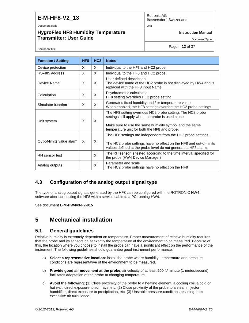
Function / Setting HF8 HC2 Notes
Device protection X X Individual to the HF8 and HC2 probe RS-485 address X X Individual to the HF8 and HC2 probe
Device Name X X User defined description The device name of the HC2 probe is not displayed by HW4 and is replaced with the HF8 Input Name
Calculation X X Psychrometric calculation HF8 setting overrides HC2 probe setting
Simulator function X X Generates fixed humidity and / or temperature value When enabled, the HF8 settings override the HC2 probe settings
Unit system X X
The HF8 setting overrides HC2 probe setting. The HC2 probe settings still apply when the probe is used alone Make sure to use the same humidity symbol and the same temperature unit for both the HF8 and probe.
Out-of-limits value alarm X X
The HF8 settings are independent from the HC2 probe settings. The HC2 probe settings have no effect on the HF8 and out-of-limits values defined at the probe level do not generate a HF8 alarm.
RH sensor test X The RH sensor is tested according to the time interval specified for the probe (HW4 Device Manager)
Analog outputs X Parameter and scale The HC2 probe settings have no effect on the HF8
4.3 Configuration of the analog output signal type The type of analog output signals generated by the HF8 can be configured with the ROTRONIC HW4 software after connecting the HF8 with a service cable to a PC running HW4. See document E-M-HW4v3-F2-015
5 Mechanical installation
5.1 General guidelines Relative humidity is extremely dependent on temperature. Proper measurement of relative humidity requires that the probe and its sensors be at exactly the temperature of the environment to be measured. Because of this, the location where you choose to install the probe can have a significant effect on the performance of the instrument. The following guidelines should guarantee good instrument performance:
a) Select a representative location: install the probe where humidity, temperature and pressure conditions are representative of the environment to be measured.
b) Provide good air movement at the probe: air velocity of at least 200 ft/ minute (1 meter/second)
facilitates adaptation of the probe to changing temperature.
c) Avoid the following: (1) Close proximity of the probe to a heating element, a cooling coil, a cold or hot wall, direct exposure to sun rays, etc. (2) Close proximity of the probe to a steam injector, humidifier, direct exposure to precipitation, etc. (3) Unstable pressure conditions resulting from excessive air turbulence.
© 2012-2013; Rotronic AG E-M-HF8-V2_20
E-M-HF8-V2_13 Rotronic AG Bassersdorf, Switzerland
Document code Unit
HygroFlex HF8 Humidity Temperature Transmitter: User Guide
Instruction Manual
Document Type
Page 13 of 37 Document title
d) Immerse as much of the probe as possible in the environment to be measured.
e) Prevent the accumulation of condensation water at the level of the sensor leads. Install the
probe so that the probe tip is looking downward. If this is not possible, install the probe horizontally.
5.2 HF8 enclosure The HF8 enclosure consists of a base and a cover held together with 4 screws. To open the enclosure, use a metric 3 mm hex key. Prior to re-assembling the enclosure, verify that the red seal is sitting properly in its groove on the base.
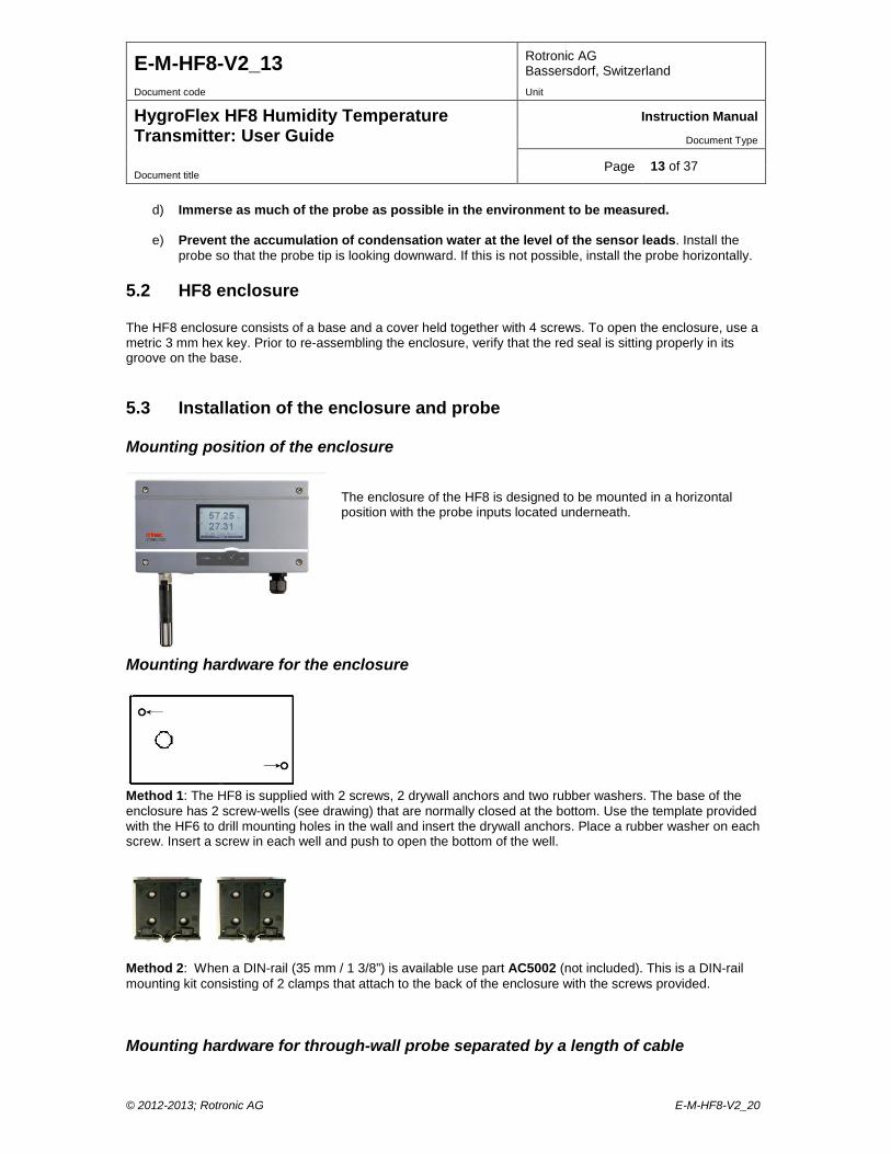
5.3 Installation of the enclosure and probe Mounting position of the enclosure
The enclosure of the HF8 is designed to be mounted in a horizontal position with the probe inputs located underneath.
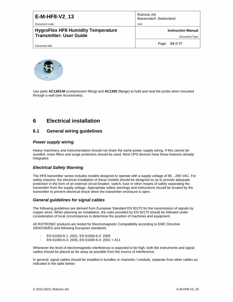
Mounting hardware for the enclosure
Method 1: The HF8 is supplied with 2 screws, 2 drywall anchors and two rubber washers. The base of the enclosure has 2 screw-wells (see drawing) that are normally closed at the bottom. Use the template provided with the HF6 to drill mounting holes in the wall and insert the drywall anchors. Place a rubber washer on each screw. Insert a screw in each well and push to open the bottom of the well.
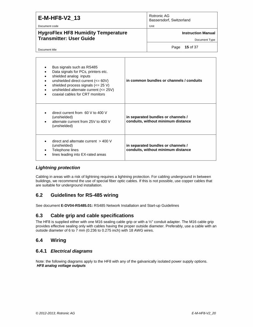
Method 2: When a DIN-rail (35 mm / 1 3/8”) is available use part AC5002 (not included). This is a DIN-rail mounting kit consisting of 2 clamps that attach to the back of the enclosure with the screws provided. Mounting hardware for through-wall probe separated by a length of cable
© 2012-2013; Rotronic AG E-M-HF8-V2_20
E-M-HF8-V2_13 Rotronic AG Bassersdorf, Switzerland
Document code Unit
HygroFlex HF8 Humidity Temperature Transmitter: User Guide
Instruction Manual
Document Type
Page 14 of 37 Document title
Use parts AC1303-M (compression fitting) and AC1305 (flange) to hold and seal the probe when mounted through a wall (see Accessories).
6 Electrical installation
6.1 General wiring guidelines Power supply wiring Heavy machinery and instrumentation should not share the same power supply wiring. If this cannot be avoided, noise filters and surge protectors should be used. Most UPS devices have those features already integrated. Electrical Safety Warning The HF8 transmitter series includes models designed to operate with a supply voltage of 85…265 VAC. For safety reasons, the electrical installation of these models should be designed so as to provide adequate protection in the form of an external circuit breaker, switch, fuse or other means of safely separating the transmitter from the supply voltage. Appropriate safety warnings and instructions should be located by the transmitter to prevent electrical shock when the transmitter enclosure is open. General guidelines for signal cables The following guidelines are derived from European Standard EN 50170 for the transmission of signals by copper wires. When planning an installation, the rules provided by EN 50170 should be followed under consideration of local circumstances to determine the position of machines and equipment. All ROTRONIC products are tested for Electromagnetic Compatibility according to EMC Directive 2004/106/EG and following European standards:
- EN 61000-6-1: 2001, EN 61000-6-2: 2005 - EN 61000-6-3: 2005, EN 61000-6-4: 2001 + A11
Whenever the level of electromagnetic interference is expected to be high, both the instruments and signal cables should be placed as far away as possible from the source of interference. In general, signal cables should be installed in bundles or channels / conduits, separate from other cables as indicated in the table below:
© 2012-2013; Rotronic AG E-M-HF8-V2_20
E-M-HF8-V2_13 Rotronic AG Bassersdorf, Switzerland
Document code Unit
HygroFlex HF8 Humidity Temperature Transmitter: User Guide
Instruction Manual
Document Type
Page 15 of 37 Document title
• Bus signals such as RS485 • Data signals for PCs, printers etc. • shielded analog inputs • unshielded direct current (<= 60V) • shielded process signals (<= 25 V) • unshielded alternate current (<= 25V) • coaxial cables for CRT monitors
in common bundles or channels / conduits
• direct current from 60 V to 400 V (unshielded)
• alternate current from 25V to 400 V (unshielded)
in separated bundles or channels / conduits, without minimum distance
• direct and alternate current > 400 V (unshielded)
• Telephone lines • lines leading into EX-rated areas
in separated bundles or channels / conduits, without minimum distance
Lightning protection Cabling in areas with a risk of lightning requires a lightning protection. For cabling underground in between buildings, we recommend the use of special fiber optic cables. If this is not possible, use copper cables that are suitable for underground installation.
6.2 Guidelines for RS-485 wiring See document E-DV04-RS485.01: RS485 Network Installation and Start-up Guidelines
6.3 Cable grip and cable specifications The HF8 is supplied either with one M16 sealing cable grip or with a ½” conduit adapter. The M16 cable grip provides effective sealing only with cables having the proper outside diameter. Preferably, use a cable with an outside diameter of 6 to 7 mm (0.236 to 0.275 inch) with 18 AWG wires.
6.4 Wiring
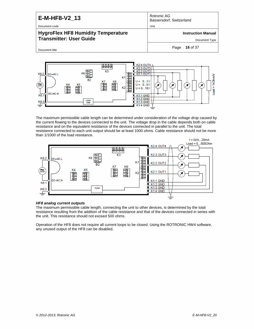
6.4.1 Electrical diagrams Note: the following diagrams apply to the HF8 with any of the galvanically isolated power supply options. HF8 analog voltage outputs
© 2012-2013; Rotronic AG E-M-HF8-V2_20
E-M-HF8-V2_13 Rotronic AG Bassersdorf, Switzerland
Document code Unit
HygroFlex HF8 Humidity Temperature Transmitter: User Guide
Instruction Manual
Document Type
Page 16 of 37 Document title
The maximum permissible cable length can be determined under consideration of the voltage drop caused by the current flowing to the devices connected to the unit. The voltage drop in the cable depends both on cable resistance and on the equivalent resistance of the devices connected in parallel to the unit. The total resistance connected to each unit output should be at least 1000 ohms. Cable resistance should not be more than 1/1000 of the load resistance.
HF8 analog current outputs The maximum permissible cable length, connecting the unit to other devices, is determined by the total resistance resulting from the addition of the cable resistance and that of the devices connected in series with the unit. This resistance should not exceed 500 ohms. Operation of the HF8 does not require all current loops to be closed. Using the ROTRONIC HW4 software, any unused output of the HF8 can be disabled.
© 2012-2013; Rotronic AG E-M-HF8-V2_20
E-M-HF8-V2_13 Rotronic AG Bassersdorf, Switzerland
Document code Unit
HygroFlex HF8 Humidity Temperature Transmitter: User Guide
Instruction Manual
Document Type
Page 17 of 37 Document title
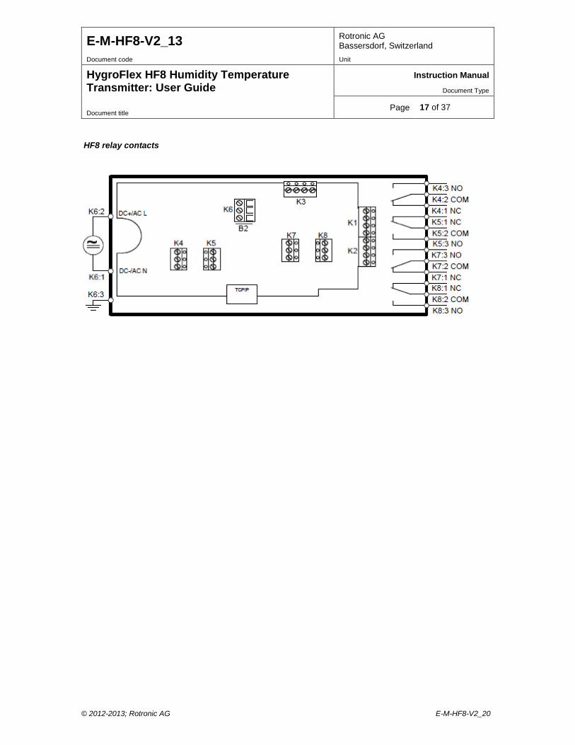
HF8 relay contacts
© 2012-2013; Rotronic AG E-M-HF8-V2_20
E-M-HF8-V2_13 Rotronic AG Bassersdorf, Switzerland
Document code Unit
HygroFlex HF8 Humidity Temperature Transmitter: User Guide
Instruction Manual
Document Type
Page 18 of 37 Document title
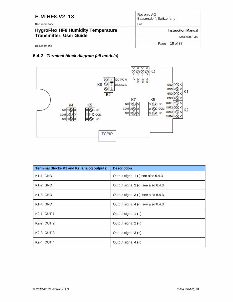
6.4.2 Terminal block diagram (all models)
Terminal Blocks K1 and K2 (analog outputs) Description
K1-1: GND Output signal 1 (-) see also 6.4.3
K1-2: GND Output signal 2 (-) see also 6.4.3
K1-3: GND Output signal 3 (-) see also 6.4.3
K1-4: GND Output signal 4 (-) see also 6.4.3
K2-1: OUT 1 Output signal 1 (+)
K2-2: OUT 2 Output signal 2 (+)
K2-3: OUT 3 Output signal 3 (+)
K2-4: OUT 4 Output signal 4 (+)
© 2012-2013; Rotronic AG E-M-HF8-V2_20
E-M-HF8-V2_13 Rotronic AG Bassersdorf, Switzerland
Document code Unit
HygroFlex HF8 Humidity Temperature Transmitter: User Guide
Instruction Manual
Document Type
Page 19 of 37 Document title
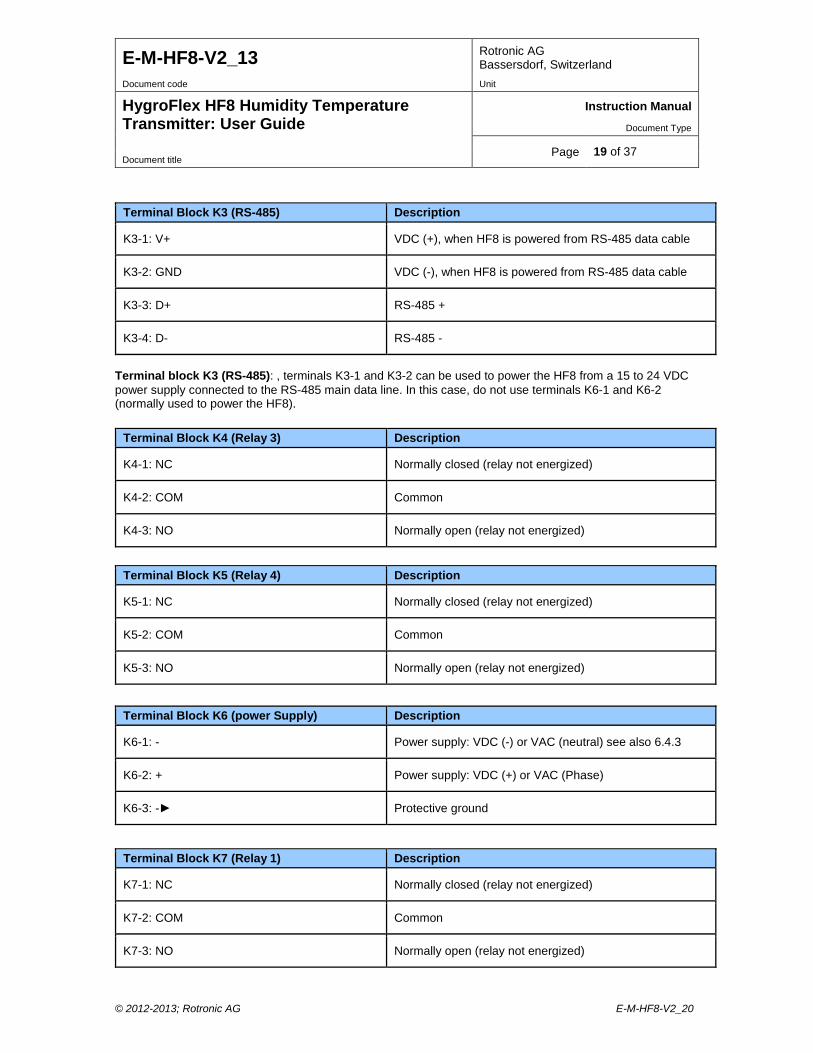
Terminal block K3 (RS-485): , terminals K3-1 and K3-2 can be used to power the HF8 from a 15 to 24 VDC power supply connected to the RS-485 main data line. In this case, do not use terminals K6-1 and K6-2 (normally used to power the HF8).
Terminal Block K3 (RS-485) Description
K3-1: V+ VDC (+), when HF8 is powered from RS-485 data cable
K3-2: GND VDC (-), when HF8 is powered from RS-485 data cable
K3-3: D+ RS-485 +
K3-4: D- RS-485 -
Terminal Block K4 (Relay 3) Description
K4-1: NC Normally closed (relay not energized)
K4-2: COM Common
K4-3: NO Normally open (relay not energized)
Terminal Block K5 (Relay 4) Description
K5-1: NC Normally closed (relay not energized)
K5-2: COM Common
K5-3: NO Normally open (relay not energized)
Terminal Block K6 (power Supply) Description
K6-1: - Power supply: VDC (-) or VAC (neutral) see also 6.4.3
K6-2: + Power supply: VDC (+) or VAC (Phase)
K6-3: - Protective ground
Terminal Block K7 (Relay 1) Description
K7-1: NC Normally closed (relay not energized)
K7-2: COM Common
K7-3: NO Normally open (relay not energized)
© 2012-2013; Rotronic AG E-M-HF8-V2_20
E-M-HF8-V2_13 Rotronic AG Bassersdorf, Switzerland
Document code Unit
HygroFlex HF8 Humidity Temperature Transmitter: User Guide
Instruction Manual
Document Type
Page 20 of 37 Document title
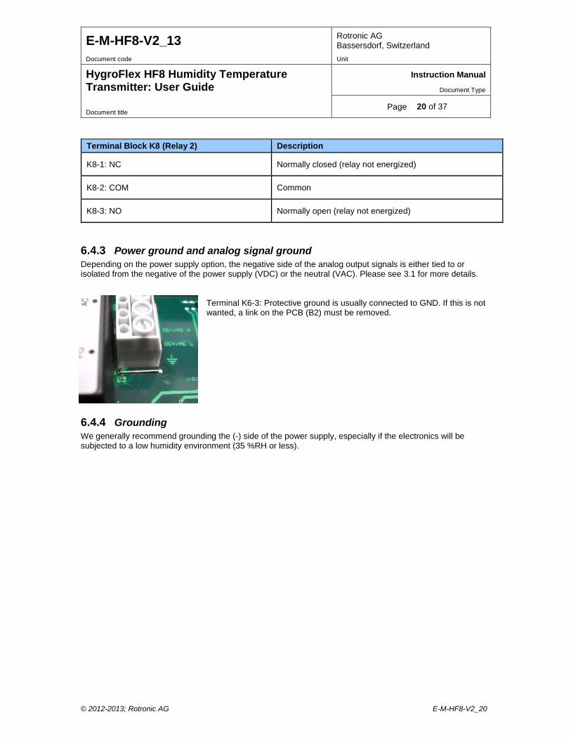
6.4.3 Power ground and analog signal ground Depending on the power supply option, the negative side of the analog output signals is either tied to or isolated from the negative of the power supply (VDC) or the neutral (VAC). Please see 3.1 for more details.
Terminal K6-3: Protective ground is usually connected to GND. If this is not wanted, a link on the PCB (B2) must be removed.
6.4.4 Grounding We generally recommend grounding the (-) side of the power supply, especially if the electronics will be subjected to a low humidity environment (35 %RH or less).
Terminal Block K8 (Relay 2) Description
K8-1: NC Normally closed (relay not energized)
K8-2: COM Common
K8-3: NO Normally open (relay not energized)
© 2012-2013; Rotronic AG E-M-HF8-V2_20
E-M-HF8-V2_13 Rotronic AG Bassersdorf, Switzerland
Document code Unit
HygroFlex HF8 Humidity Temperature Transmitter: User Guide
Instruction Manual
Document Type
Page 21 of 37 Document title
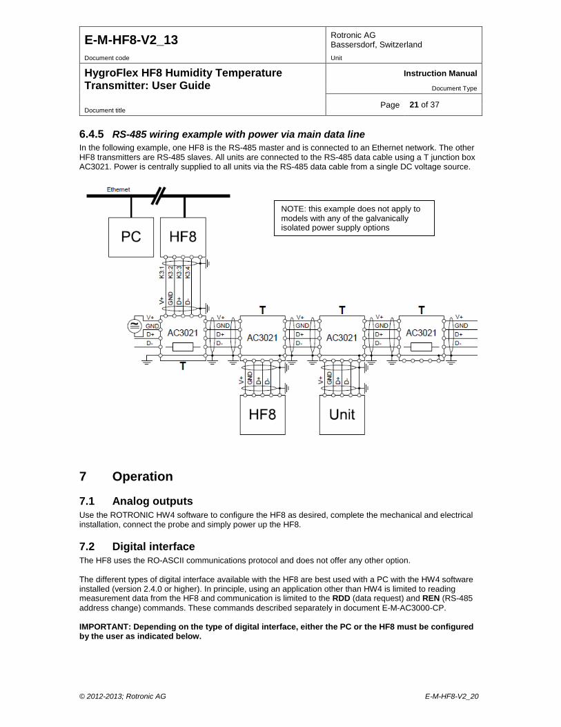
6.4.5 RS-485 wiring example with power via main data line In the following example, one HF8 is the RS-485 master and is connected to an Ethernet network. The other HF8 transmitters are RS-485 slaves. All units are connected to the RS-485 data cable using a T junction box AC3021. Power is centrally supplied to all units via the RS-485 data cable from a single DC voltage source.
7 Operation
7.1 Analog outputs Use the ROTRONIC HW4 software to configure the HF8 as desired, complete the mechanical and electrical installation, connect the probe and simply power up the HF8.
7.2 Digital interface The HF8 uses the RO-ASCII communications protocol and does not offer any other option. The different types of digital interface available with the HF8 are best used with a PC with the HW4 software installed (version 2.4.0 or higher). In principle, using an application other than HW4 is limited to reading measurement data from the HF8 and communication is limited to the RDD (data request) and REN (RS-485 address change) commands. These commands described separately in document E-M-AC3000-CP. IMPORTANT: Depending on the type of digital interface, either the PC or the HF8 must be configured by the user as indicated below.
NOTE: this example does not apply to models with any of the galvanically isolated power supply options
© 2012-2013; Rotronic AG E-M-HF8-V2_20
E-M-HF8-V2_13 Rotronic AG Bassersdorf, Switzerland
Document code Unit
HygroFlex HF8 Humidity Temperature Transmitter: User Guide
Instruction Manual
Document Type
Page 22 of 37 Document title
7.2.1 Ethernet (TCP/IP) interface Prior to connecting the HF8 to an active Ethernet network you must configure the TCP/IP settings of the HF8 using either the HW4 software (version 2.4.0 or higher) or the TCP/IP configuration tool available from www.rotronic-humidity.com. For instructions see the HW4 manual E-M-HW4v3-Main (§ 7.4) and technical note IN-E-TCPIP-Conf WARNING: Connecting a device to an active Ethernet network can disrupt communications on the network. Before connecting the HF8, make sure that it is properly configured for your network
7.2.2 RS-485 serial interface (multi-drop) Instructions for using the HF8 with a RS-485 network are provided in the following manuals: E-M-HW4v3-Main (§ 7.5), E-M-HW4v3-F2-015 and E-DV04-RS485.01. Notes: o Instruments connected to the same RS-485 network must use the same baud rate and each instrument
must be given a unique RS-485 address (the address requirement applies to the HF8 but not to its probes)
o RS-485 Compatibility: The HF8 uses the RO-ASCII communications protocol. This protocol is not compatible with the protocol used by both the previous generation of ROTRONIC products and by the HygroLog HL-NT data logger. Do not connect legacy products or the HL-NT data logger to the same RS-485 network as HF8.
The specifications of the RS-485 interface are as follows: Baud rate : 19200 Parity : none Data bits : 8 Stop bits : 1
© 2012-2013; Rotronic AG E-M-HF8-V2_20
E-M-HF8-V2_13 Rotronic AG Bassersdorf, Switzerland
Document code Unit
HygroFlex HF8 Humidity Temperature Transmitter: User Guide
Instruction Manual
Document Type
Page 23 of 37 Document title
7.3 Optional display and keypad
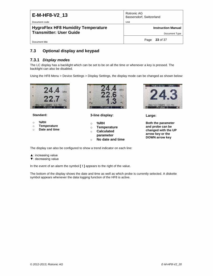
7.3.1 Display modes The LC display has a backlight which can be set to be on all the time or whenever a key is pressed. The backlight can also be disabled. Using the HF8 Menu > Device Settings > Display Settings, the display mode can be changed as shown below:
The display can also be configured to show a trend indicator on each line: : increasing value : decreasing value In the event of an alarm the symbol [ ! ] appears to the right of the value. The bottom of the display shows the date and time as well as which probe is currently selected. A diskette symbol appears whenever the data logging function of the HF8 is active.
Standard:
o %RH o Temperature o Date and time
3-line display: o %RH o Temperature o Calculated
parameter o No date and time
Large: Both the parameter and probe can be changed with the UP arrow key or the DOWN arrow key
© 2012-2013; Rotronic AG E-M-HF8-V2_20
E-M-HF8-V2_13 Rotronic AG Bassersdorf, Switzerland
Document code Unit
HygroFlex HF8 Humidity Temperature Transmitter: User Guide
Instruction Manual
Document Type
Page 24 of 37 Document title
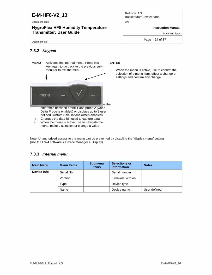
7.3.2 Keypad
Note: Unauthorized access to the menu can be prevented by disabling the “display menu” setting (use the HW4 software > Device Manager > Display)
7.3.3 Internal menu
Main Menu Menu Items Submenu Items
Selections or Information Notes
Device Info Serial Nbr Serial number
Version Firmware version
Type Device type
Name Device name User defined
MENU Activates the internal menu. Press this key again to go back to the previous sub-menu or to exit the menu
- / + o Changes the probe being displayed or displays the
difference between probe 1 and probe 2 (when Delta Probe is enabled) or displays up to 2 user defined Custom Calculations (when enabled)
o Changes the data-bin used to capture data o When the menu is active, use to navigate the
menu, make a selection or change a value
ENTER o When the menu is active, use to confirm the
selection of a menu item, effect a change of settings and confirm any change
© 2012-2013; Rotronic AG E-M-HF8-V2_20
E-M-HF8-V2_13 Rotronic AG Bassersdorf, Switzerland
Document code Unit
HygroFlex HF8 Humidity Temperature Transmitter: User Guide
Instruction Manual
Document Type
Page 25 of 37 Document title
Main Menu Menu Items Submenu Items
Selections or Information Notes
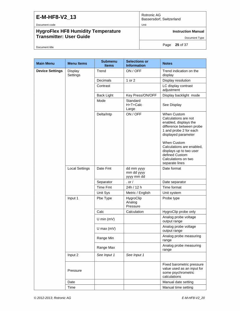
Device Settings Display Settings
Trend ON / OFF Trend indication on the display
Decimals 1 or 2 Display resolution Contrast LC display contrast
adjustment Back Light Key Press/ON/OFF Display backlight mode Mode Standard
H+T+Calc Large
See Display
Delta/Intp ON / OFF When Custom Calculations are not enabled, displays the difference between probe 1 and probe 2 for each displayed parameter When Custom Calculations are enabled, displays up to two user defined Custom Calculations on two separate lines
Local Settings Date Fmt dd mm yyyy mm dd yyyy yyyy mm dd
Date format
Separator . or / Date separator Time Fmt 24h / 12 h Time format Unit Sys Metric / English Unit system
Input 1 Pbe Type HygroClip Analog Pressure
Probe type
Calc Calculation HygroClip probe only
U min (mV) Analog probe voltage output range
U max (mV) Analog probe voltage output range
Range Min Analog probe measuring range
Range Max Analog probe measuring range
Input 2
See Input 1 See Input 1
Pressure
Fixed barometric pressure value used as an input for some psychrometric calculations
Date Manual date setting Time Manual time setting
© 2012-2013; Rotronic AG E-M-HF8-V2_20
E-M-HF8-V2_13 Rotronic AG Bassersdorf, Switzerland
Document code Unit
HygroFlex HF8 Humidity Temperature Transmitter: User Guide
Instruction Manual
Document Type
Page 26 of 37 Document title
Main Menu Menu Items Submenu Items
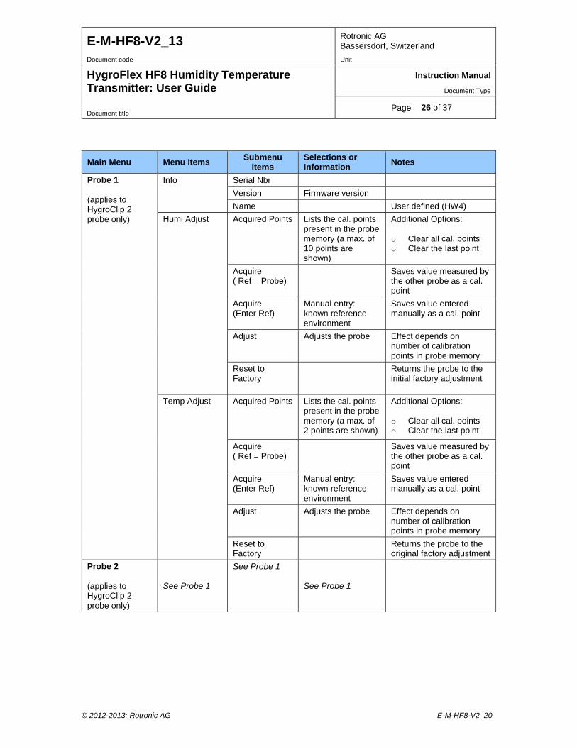
Selections or Information Notes
Probe 1 (applies to HygroClip 2 probe only)
Info Serial Nbr Version Firmware version Name User defined (HW4)
Humi Adjust Acquired Points Lists the cal. points present in the probe memory (a max. of 10 points are shown)
Additional Options: o Clear all cal. points o Clear the last point
Acquire ( Ref = Probe)
Saves value measured by the other probe as a cal. point
Acquire (Enter Ref)
Manual entry: known reference environment
Saves value entered manually as a cal. point
Adjust Adjusts the probe Effect depends on number of calibration points in probe memory
Reset to Factory
Returns the probe to the initial factory adjustment
Temp Adjust Acquired Points Lists the cal. points present in the probe memory (a max. of 2 points are shown)
Additional Options: o Clear all cal. points o Clear the last point
Acquire ( Ref = Probe)
Saves value measured by the other probe as a cal. point
Acquire (Enter Ref)
Manual entry: known reference environment
Saves value entered manually as a cal. point
Adjust Adjusts the probe Effect depends on number of calibration points in probe memory
Reset to Factory
Returns the probe to the original factory adjustment
Probe 2 (applies to HygroClip 2 probe only)
See Probe 1
See Probe 1
See Probe 1
© 2012-2013; Rotronic AG E-M-HF8-V2_20
E-M-HF8-V2_13 Rotronic AG Bassersdorf, Switzerland
Document code Unit
HygroFlex HF8 Humidity Temperature Transmitter: User Guide
Instruction Manual
Document Type
Page 27 of 37 Document title
Main Menu Menu Items Submenu Items
Selections or Information Notes
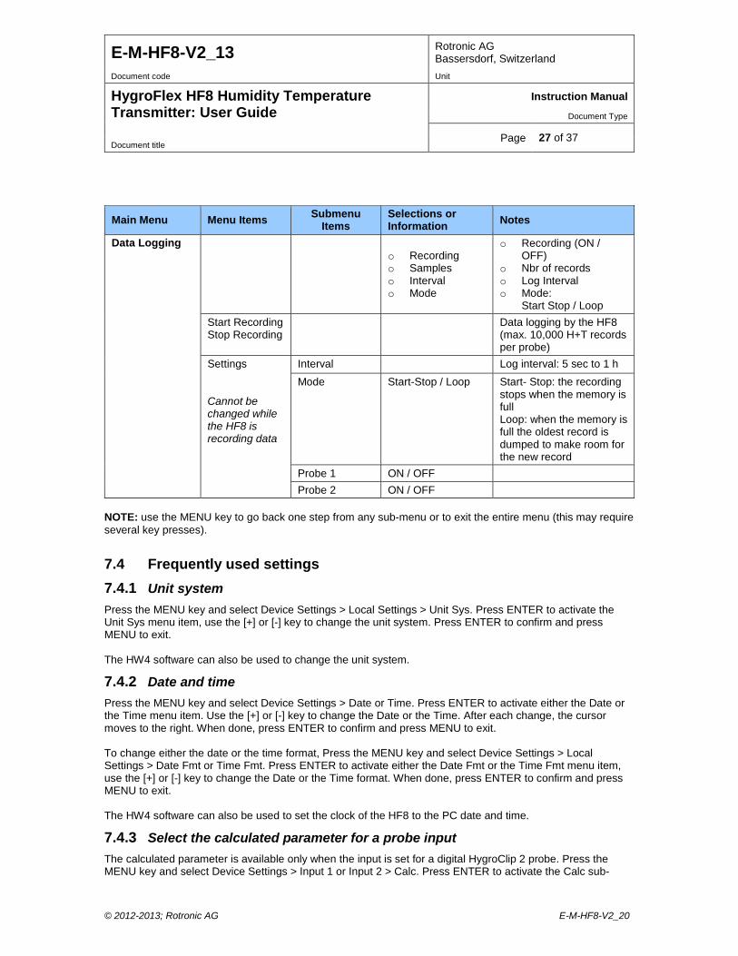
Data Logging
o Recording o Samples o Interval o Mode
o Recording (ON / OFF)
o Nbr of records o Log Interval o Mode:
Start Stop / Loop Start Recording Stop Recording
Data logging by the HF8 (max. 10,000 H+T records per probe)
Settings Cannot be changed while the HF8 is recording data
Interval Log interval: 5 sec to 1 h Mode Start-Stop / Loop Start- Stop: the recording
stops when the memory is full Loop: when the memory is full the oldest record is dumped to make room for the new record
Probe 1 ON / OFF Probe 2 ON / OFF
NOTE: use the MENU key to go back one step from any sub-menu or to exit the entire menu (this may require several key presses).
7.4 Frequently used settings 7.4.1 Unit system Press the MENU key and select Device Settings > Local Settings > Unit Sys. Press ENTER to activate the Unit Sys menu item, use the [+] or [-] key to change the unit system. Press ENTER to confirm and press MENU to exit. The HW4 software can also be used to change the unit system.
7.4.2 Date and time Press the MENU key and select Device Settings > Date or Time. Press ENTER to activate either the Date or the Time menu item. Use the [+] or [-] key to change the Date or the Time. After each change, the cursor moves to the right. When done, press ENTER to confirm and press MENU to exit. To change either the date or the time format, Press the MENU key and select Device Settings > Local Settings > Date Fmt or Time Fmt. Press ENTER to activate either the Date Fmt or the Time Fmt menu item, use the [+] or [-] key to change the Date or the Time format. When done, press ENTER to confirm and press MENU to exit. The HW4 software can also be used to set the clock of the HF8 to the PC date and time.
7.4.3 Select the calculated parameter for a probe input The calculated parameter is available only when the input is set for a digital HygroClip 2 probe. Press the MENU key and select Device Settings > Input 1 or Input 2 > Calc. Press ENTER to activate the Calc sub-
© 2012-2013; Rotronic AG E-M-HF8-V2_20
E-M-HF8-V2_13 Rotronic AG Bassersdorf, Switzerland
Document code Unit
HygroFlex HF8 Humidity Temperature Transmitter: User Guide
Instruction Manual
Document Type
Page 28 of 37 Document title
menu, use the [+] or [-] key to select the calculated parameter. Press ENTER to confirm and press MENU to exit.
7.4.4 Select which probe and/or parameters are shown on the display Press the MENU key and select Device Settings > Display Settings > Mode. Press ENTER to activate the Mode menu item, use the [+] or [-] key to select the display mode. Press ENTER to confirm and press MENU to exit. Depending on the display mode, use the [+] or [-] key to change the probe and/or parameter being displayed. NOTE: The calculated parameter (HygroClip 2 probe only) is shown only if enabled for the probe input that is selected (MENU > Input 1 or Input 2 > Calc).
7.4.5 Set input 1 or 2 for a digital or analog probe Press the MENU key and select Device Settings > Input 1 or Input 2 > Pbe Type. Press ENTER to activate the Pbe Type menu item, use the [+] or [-] key to change the probe type. Press ENTER to confirm and press MENU to exit. When using an analog probe, be sure to define both the voltage signal range and the measuring range of the probe. HW4 is required to define the unit of measurement of an analog probe. The HW4 software can also be used to change the probe type for each input.
7.5 Data logging function The HF8 can log up to 10,000 pairs of relative humidity and temperature values provided by a single HygroClip 2 probe or up to 10,000 data values provided by a single 1-channel analog probe. Both probe inputs can be logged at the same time and in that case the recording capacity per probe is cut in half. Each record is automatically date and time stamped. The calculated parameter cannot be recorded.
7.5.1 Logging data The data logging settings apply to both probe inputs Data logging starts and ends simultaneously for both probe inputs The log data function settings cannot be changed as long as data logging is active
Configure the data logging function and start recording data:
o Press the MENU key and select “Data Logging”. Press ENTER to activate the Data Logging menu. o Use the + or - key to select Settings. Press ENTER to confirm and open the Settings sub-menu. Use
the + or - key to select a menu item and press ENTER to confirm: o Select Interval (log interval). Press ENTER to activate the Interval menu item and use the + or - key
to change the log interval. Press ENTER after each change to confirm and move the cursor to the right. When done, press ENTER to confirm and exit.
o Use the + or - key to select the Mode menu item. Press ENTER to activate the Mode menu item and use the + or - key to change the logging mode: - Start-Stop. the recording will stop when the memory is full - Loop: when the memory is full the oldest record will be dumped to make room for the next record When done, press ENTER to confirm and exit.
o Use the + or - key to select each probe to be logged. Press ENTER to activate the Probe 1 or Probe 2 menu item and use the + or - key to enable data logging. Press ENTER to confirm and exit.
o Press the MENU key and use the - to select Start Recording o Press the ENTER key twice to start recording data o The HF8 automatically exits the data logging function and a diskette symbol appears at the bottom
left of the display for each probe being recorded
© 2012-2013; Rotronic AG E-M-HF8-V2_20

E-M-HF8-V2_13 Rotronic AG Bassersdorf, Switzerland
Document code Unit
HygroFlex HF8 Humidity Temperature Transmitter: User Guide
Instruction Manual
Document Type
Page 29 of 37 Document title
Stop recording data:
o Press the MENU key and select Data Logging. Press ENTER to activate the Data Logging menu item.
o Use the + or - key to select Stop Recording. Press ENTER twice to confirm. The HF8 automatically exits the data logging function.
7.5.2 Viewing the recorded data Data recorded with the HF8 data logging function can be viewed only after connecting the HF8 to a PC with the HW4 software running. For instructions see the following HW4 manual: E-M-HW4v3-F2-015.
7.6 Relay contacts The relay contacts can be configured after using a service cable to connect the HF8 to a PC running the ROTRONIC HW4 software. Instructions are provided in the following HW4 manual: E-M-HW4v3-F2-015
7.7 Audible alarm (beeper) The audible alarm can be disabled, enabled and configured after using a service cable to connect HF8 to a PC running the ROTRONIC HW4 software. Instructions are provided in the following HW4 manual: E-M-HW4v3-F2-015
8 Maintenance The HF8 transmitter does not require any particular maintenance from an electrical safety standpoint.
8.1 Service cable Cable AC3006 is used to connect the HF8 to a USB port of a PC running the ROTRONIC HW4 software. Prior to connecting the HF5 to a USB port you must install the ROTRONIC USB driver on the PC (available from the HW4 CD or from www.rotronic-humidity.com). For instructions see the HW4 manual E-M-HW4v3-Main.
8.2 Location of the service connector (mini USB type) WARNING: the service connector is a UART interface with a mini-USB connector type. Do not connect the service connector directly to the USB port of a PC or hub.
The service connector (see arrow for location) can be accessed without opening the enclosure after removing the small red sealing cover.
© 2012-2013; Rotronic AG E-M-HF8-V2_20
E-M-HF8-V2_13 Rotronic AG Bassersdorf, Switzerland
Document code Unit
HygroFlex HF8 Humidity Temperature Transmitter: User Guide
Instruction Manual
Document Type
Page 30 of 37 Document title
8.3 Periodic calibration check of the HygroClip 2 probe Both the Pt 100 RTD temperature sensor used in the HygroClip 2 probe and associated electronics are very stable and should not require any calibration after the initial factory adjustment. Long term stability of the ROTRONIC Hygromer humidity sensor is typically better than 1 %RH per year. For maximum accuracy, calibration of the probe should be verified every 6 to 12 months. Applications where the probe is exposed to significant pollution may require more frequent verifications.
8.4 HF8 probe calibration and adjustment procedures The HF8 uses two separate steps:
1) Acquisition and capture of calibration points to the memory of the HygroClip 2 probe 2) Adjustment of the probe based on the calibration points present in the probe memory
When the purpose is just to calibrate a HygroClip 2 probe, use only step 1. Up to 2 temperature calibration points and up to100 humidity calibration points can be held indefinitely in the probe memory. No calibration point is saved within the HF8 itself. A calibration protocol can be printed with the HW4 software. Either the HW4 software or the HF8 can be used at any time to delete unwanted calibration points from the probe or device memory. Adjustment (step 2) can be carried out at any time after calibration, even several days later. Adjustment is purely an electronic process based on the data memorized by the probe. Note: Instructions for using the ROTRONIC calibration devices and humidity standards are provided in document E-M-CalBasics
8.4.1 Calibration against a reference probe The HF8 can be used to do a 1-point or multi-point calibration of a probe connected to one of the HF8 probe inputs against a reference HygroClip 2 probe connected to the other probe input of the HF8. Expose both the reference probe and the probe to be calibrated to the same environment and wait for full equilibrium with the environment. In a still air environment, it is highly recommended to provide some ventilation that is common to both the reference probe and device to be adjusted.
o Press the MENU key and select either “Probe 1” or “Probe 2”. The reference probe is assumed to be connected to the non-selected input. Press ENTER to activate the Probe 1 or Probe 2 menu item.
o Use the [-] key to select either “Humi Adjust” or “Temp Adjust” (this can be done in any order). o Press ENTER to confirm and open the next sub-menu. Use the [-] key to select the “Acquire (Ref =
Probe)” menu item and press ENTER to confirm. o Humi Adjust: the HF8 displays both the current humidity read by the device to be calibrated and the
value provided by the reference probe. Press ENTER to accept the calibration point. Press ENTER to confirm and save the calibration point to the device memory. The HF8 automatically exits the menu.
o Temp Adjust: the HF8 displays both the current temperature read by the device to be calibrated and the value provided by the reference probe. Press ENTER to accept the calibration point. Press ENTER to confirm and save the calibration point to the device memory. The HF8 automatically exits the menu.
Note: the procedure can be repeated under different conditions so as to accumulate several calibration points (temperature: maximum 2 points, humidity: maximum 100 points).
© 2012-2013; Rotronic AG E-M-HF8-V2_20
E-M-HF8-V2_13 Rotronic AG Bassersdorf, Switzerland
Document code Unit
HygroFlex HF8 Humidity Temperature Transmitter: User Guide
Instruction Manual
Document Type
Page 31 of 37 Document title
8.4.2 Calibration against a reference environment The HF8 can be used to do a 1-point or multi-point calibration of up to two probes against a known reference environment. Expose the probe or probes to be calibrated to the reference environment and wait for full equilibrium with the environment. In a still air environment, it is highly recommended to provide some ventilation that is common to the devices being calibrated.
o Press the MENU key and select either “Probe 1” or “Probe 2”. Press ENTER to activate the Probe 1 or Probe 2 menu item.
o Use the [-] key to select either “Humi Adjust” or “Temp Adjust” (this can be done in any order). o Press ENTER to confirm and open the next sub-menu. Use the DOWN arrow key to select the
“Acquire (Enter Ref)” menu item and press ENTER to confirm. o Humi Adjust: the HF8 displays both the current humidity read by the probe to be calibrated and the
reference humidity (known environment). Press ENTER to activate the reference value menu item and use the [+] or [-] key to change each digit. Press ENTER to move the cursor to the right. When done, press ENTER to save the value. Use the [-] key to select <Acquire>. Press ENTER to activate the Acquire function. Press ENTER to confirm and save the calibration point to the device memory. The HF8 automatically exits the menu.
o Temp Adjust: the HF8 displays both the current temperature read by the device to be calibrated and the reference temperature (known environment). Press ENTER to activate the reference value menu item and use the [+] or [-] key to change each digit. Press ENTER to move the cursor to the right. When done, press ENTER to save the value. Use the [-] key to select <Acquire>. Press ENTER to activate the Acquire function. Press ENTER to confirm and save the calibration point to the device memory. The HF8 automatically exits the menu.
Note: the procedure can be repeated with different reference environments so as to accumulate several calibration points (temperature: maximum 2 points, humidity: maximum 100 points).
8.4.3 Adjustment of humidity and temperature The HF8 can be used to do a 1-point or multi-point humidity and temperature adjustment of up to two probes. Humidity and temperature adjustment are two separate processes.
o Press the MENU key and select either “Probe 1” or “Probe 2”. Press ENTER to activate the Probe 1 or Probe 2 menu item.
o Use the [-] key to select either “Temp Adjust” or “Humi Adjust” (we recommend selecting Temp Adjust first). The following steps are the same for a temperature or a humidity adjustment.
o Press ENTER to confirm and open the next sub-menu. o Optional: with the “Acquired Points” menu item selected press ENTER and review the calibration
points present in memory. This submenu allows you to delete unwanted calibration points. Press MENU when done.
o Use the [-] key to select the “Adjust” menu item and press ENTER to confirm. o Press ENTER to activate the Adjust function. This function automatically erases the calibration points
in memory. When done adjusting, the HF8 automatically exits the menu.
© 2012-2013; Rotronic AG E-M-HF8-V2_20
E-M-HF8-V2_13 Rotronic AG Bassersdorf, Switzerland
Document code Unit
HygroFlex HF8 Humidity Temperature Transmitter: User Guide
Instruction Manual
Document Type
Page 32 of 37 Document title
8.5 Cleaning or replacing the probe dust filter See document E-M-HC2 Probes-V1
8.6 Validation of the output signals transmission If so desired, transmission of the HF8 output signals can be validated by using the simulator function. The HW4 software is required to enable and configure this function. When this function is enabled the HF8 generates fixed digital and analog signals as specified by the user. For instructions see document E-M-HW4v3-F2-015
9 Firmware updates Firmware updates will be available on the ROTRONIC website for downloading. Firmware files are given a name that shows both to which device the file applies and the version number of the firmware. All firmware files have the extension HEX. Procedure for updating the firmware: • Use cable AC3006 to connect the service port of the HF8 to a USB port of a PC with the ROTRONIC
HW4 software installed. Note that the ROTRONIC USB driver must be installed on the PC as explained in the HW4 manual E-M-HW4v3-Main. In the case of a model with digital interface, a connection with the PC can be established via the USB (ROTRONIC USB driver), Ethernet or RS-485 interface.
• Copy the firmware update file from the ROTRONIC website to the PC. • Start HW4 software on the PC and search for the HF8 (HW4 Main Menu Bar > Devices and Groups
> Search for USB Masters). • After finding the HF8, expand the device tree to see the HF8 functions. Select Device Manager. In
the Device Manager menu bar select Tools > Firmware Update. For instructions see document E-M-HW4v3-F2-015
© 2012-2013; Rotronic AG E-M-HF8-V2_20
E-M-HF8-V2_13 Rotronic AG Bassersdorf, Switzerland
Document code Unit
HygroFlex HF8 Humidity Temperature Transmitter: User Guide
Instruction Manual
Document Type
Page 33 of 37 Document title
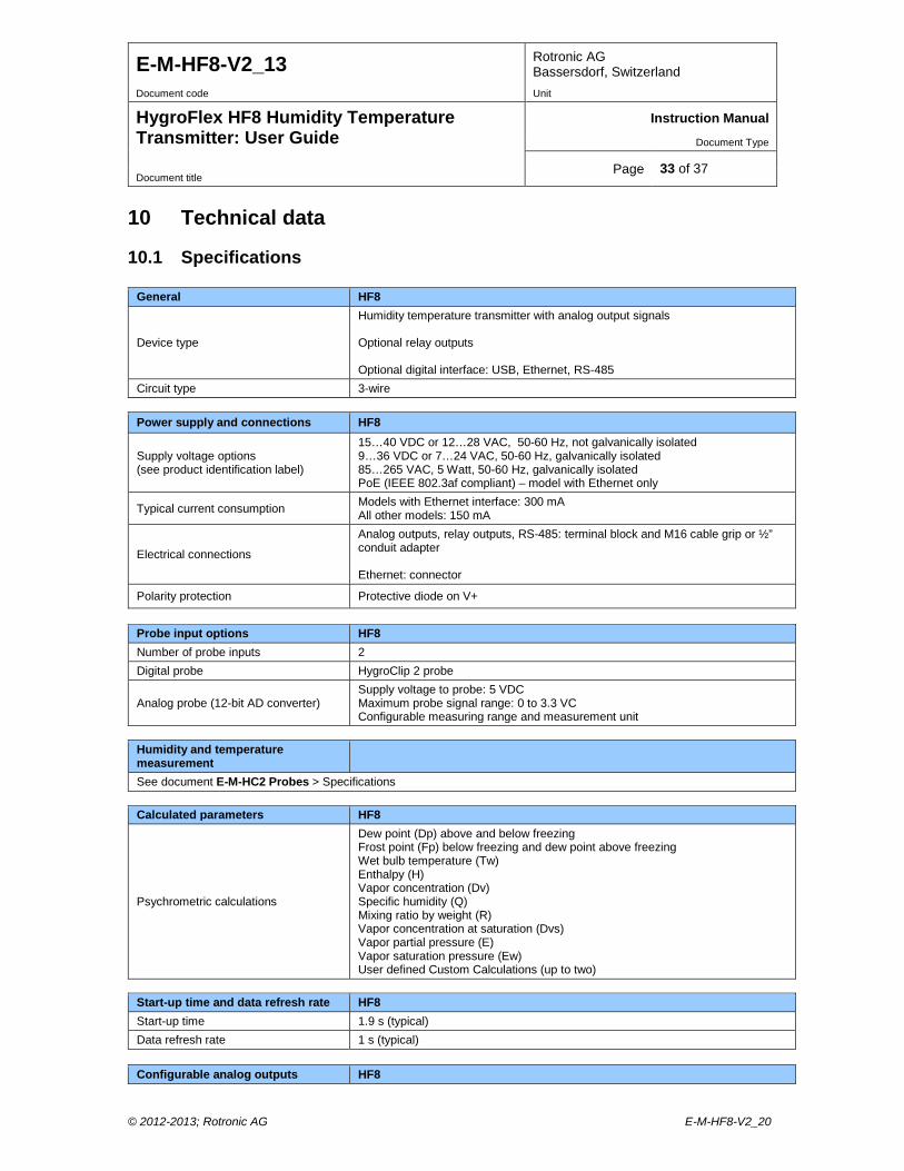
10 Technical data
10.1 Specifications
General HF8
Device type
Humidity temperature transmitter with analog output signals Optional relay outputs Optional digital interface: USB, Ethernet, RS-485
Circuit type 3-wire
Power supply and connections HF8
Supply voltage options (see product identification label)
15…40 VDC or 12…28 VAC, 50-60 Hz, not galvanically isolated 9…36 VDC or 7…24 VAC, 50-60 Hz, galvanically isolated 85…265 VAC, 5 Watt, 50-60 Hz, galvanically isolated PoE (IEEE 802.3af compliant) – model with Ethernet only
Typical current consumption Models with Ethernet interface: 300 mA All other models: 150 mA
Electrical connections
Analog outputs, relay outputs, RS-485: terminal block and M16 cable grip or ½” conduit adapter Ethernet: connector
Polarity protection Protective diode on V+
Probe input options HF8 Number of probe inputs 2 Digital probe HygroClip 2 probe
Analog probe (12-bit AD converter) Supply voltage to probe: 5 VDC Maximum probe signal range: 0 to 3.3 VC Configurable measuring range and measurement unit
Humidity and temperature measurement
See document E-M-HC2 Probes > Specifications
Calculated parameters HF8
Psychrometric calculations
Dew point (Dp) above and below freezing Frost point (Fp) below freezing and dew point above freezing Wet bulb temperature (Tw) Enthalpy (H) Vapor concentration (Dv) Specific humidity (Q) Mixing ratio by weight (R) Vapor concentration at saturation (Dvs) Vapor partial pressure (E) Vapor saturation pressure (Ew) User defined Custom Calculations (up to two)
Start-up time and data refresh rate HF8 Start-up time 1.9 s (typical) Data refresh rate 1 s (typical)
Configurable analog outputs HF8
© 2012-2013; Rotronic AG E-M-HF8-V2_20
E-M-HF8-V2_13 Rotronic AG Bassersdorf, Switzerland
Document code Unit
HygroFlex HF8 Humidity Temperature Transmitter: User Guide
Instruction Manual
Document Type
Page 34 of 37 Document title
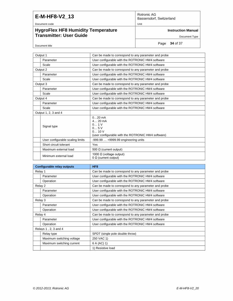
Output 1 Can be made to correspond to any parameter and probe Parameter User configurable with the ROTRONIC HW4 software Scale User configurable with the ROTRONIC HW4 software Output 2 Can be made to correspond to any parameter and probe Parameter User configurable with the ROTRONIC HW4 software Scale User configurable with the ROTRONIC HW4 software Output 3 Can be made to correspond to any parameter and probe Parameter User configurable with the ROTRONIC HW4 software Scale User configurable with the ROTRONIC HW4 software Output 4 Can be made to correspond to any parameter and probe Parameter User configurable with the ROTRONIC HW4 software Scale User configurable with the ROTRONIC HW4 software Output 1, 2, 3 and 4
Signal type
0…20 mA 4… 20 mA 0… 1 V 0… 5 V 0… 10 V (user configurable with the ROTRONIC HW4 software)
User configurable scaling limits -999.99 … +9999.99 engineering units Short circuit tolerant Yes Maximum external load 500 Ω (current output)
Minimum external load 1000 Ω (voltage output) 0 Ω (current output)
Configurable relay outputs HF8 Relay 1 Can be made to correspond to any parameter and probe Parameter User configurable with the ROTRONIC HW4 software Operation User configurable with the ROTRONIC HW4 software Relay 2 Can be made to correspond to any parameter and probe Parameter User configurable with the ROTRONIC HW4 software Operation User configurable with the ROTRONIC HW4 software Relay 3 Can be made to correspond to any parameter and probe Parameter User configurable with the ROTRONIC HW4 software Operation User configurable with the ROTRONIC HW4 software Relay 4 Can be made to correspond to any parameter and probe Parameter User configurable with the ROTRONIC HW4 software Operation User configurable with the ROTRONIC HW4 software Relays 1 , 2, 3 and 4 Relay type SPDT (single pole double throw) Maximum switching voltage 250 VAC 1) Maximum switching current 6 A (AC) 1) 1) Resistive load
© 2012-2013; Rotronic AG E-M-HF8-V2_20
E-M-HF8-V2_13 Rotronic AG Bassersdorf, Switzerland
Document code Unit
HygroFlex HF8 Humidity Temperature Transmitter: User Guide
Instruction Manual
Document Type
Page 35 of 37 Document title
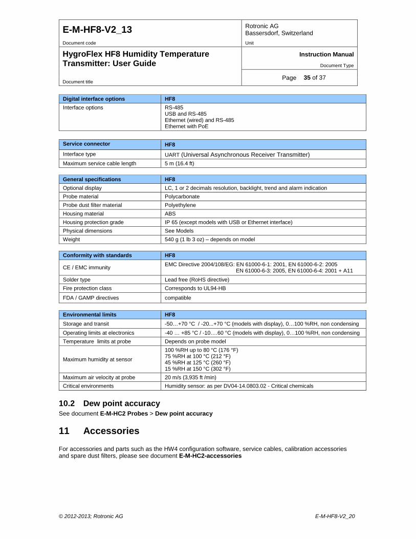
Digital interface options HF8 Interface options RS-485
USB and RS-485 Ethernet (wired) and RS-485 Ethernet with PoE
Service connector HF8 Interface type UART (Universal Asynchronous Receiver Transmitter) Maximum service cable length 5 m (16.4 ft)
General specifications HF8 Optional display LC, 1 or 2 decimals resolution, backlight, trend and alarm indication Probe material Polycarbonate Probe dust filter material Polyethylene Housing material ABS Housing protection grade IP 65 (except models with USB or Ethernet interface) Physical dimensions See Models Weight 540 g (1 lb 3 oz) – depends on model
Conformity with standards HF8
CE / EMC immunity EMC Directive 2004/108/EG: EN 61000-6-1: 2001, EN 61000-6-2: 2005 EN 61000-6-3: 2005, EN 61000-6-4: 2001 + A11
Solder type Lead free (RoHS directive) Fire protection class Corresponds to UL94-HB
FDA / GAMP directives compatible
Environmental limits HF8 Storage and transit -50…+70 °C / -20...+70 °C (models with display), 0…100 %RH, non condensing Operating limits at electronics -40 … +85 °C / -10….60 °C (models with display), 0…100 %RH, non condensing Temperature limits at probe Depends on probe model
Maximum humidity at sensor
100 %RH up to 80 °C (176 °F) 75 %RH at 100 °C (212 °F) 45 %RH at 125 °C (260 °F) 15 %RH at 150 °C (302 °F)
Maximum air velocity at probe 20 m/s (3,935 ft /min) Critical environments Humidity sensor: as per DV04-14.0803.02 - Critical chemicals
10.2 Dew point accuracy See document E-M-HC2 Probes > Dew point accuracy
11 Accessories For accessories and parts such as the HW4 configuration software, service cables, calibration accessories and spare dust filters, please see document E-M-HC2-accessories
© 2012-2013; Rotronic AG E-M-HF8-V2_20
E-M-HF8-V2_13 Rotronic AG Bassersdorf, Switzerland
Document code Unit
HygroFlex HF8 Humidity Temperature Transmitter: User Guide
Instruction Manual
Document Type
Page 36 of 37 Document title
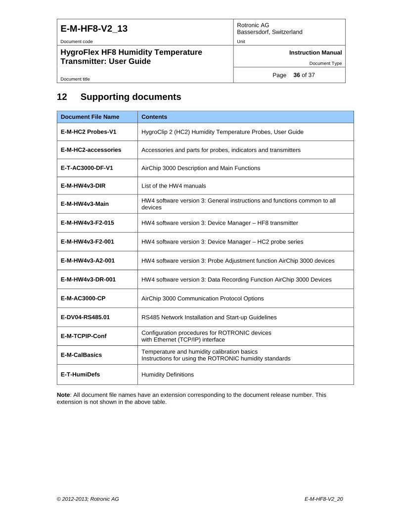
12 Supporting documents
Document File Name Contents
E-M-HC2 Probes-V1 HygroClip 2 (HC2) Humidity Temperature Probes, User Guide
E-M-HC2-accessories Accessories and parts for probes, indicators and transmitters
E-T-AC3000-DF-V1 AirChip 3000 Description and Main Functions
E-M-HW4v3-DIR List of the HW4 manuals
E-M-HW4v3-Main HW4 software version 3: General instructions and functions common to all devices
E-M-HW4v3-F2-015 HW4 software version 3: Device Manager – HF8 transmitter
E-M-HW4v3-F2-001 HW4 software version 3: Device Manager – HC2 probe series
E-M-HW4v3-A2-001 HW4 software version 3: Probe Adjustment function AirChip 3000 devices
E-M-HW4v3-DR-001 HW4 software version 3: Data Recording Function AirChip 3000 Devices
E-M-AC3000-CP AirChip 3000 Communication Protocol Options
E-DV04-RS485.01 RS485 Network Installation and Start-up Guidelines
E-M-TCPIP-Conf Configuration procedures for ROTRONIC devices with Ethernet (TCP/IP) interface
E-M-CalBasics Temperature and humidity calibration basics Instructions for using the ROTRONIC humidity standards
E-T-HumiDefs Humidity Definitions
Note: All document file names have an extension corresponding to the document release number. This extension is not shown in the above table.
© 2012-2013; Rotronic AG E-M-HF8-V2_20
E-M-HF8-V2_13 Rotronic AG Bassersdorf, Switzerland
Document code Unit
HygroFlex HF8 Humidity Temperature Transmitter: User Guide
Instruction Manual
Document Type
Page 37 of 37 Document title
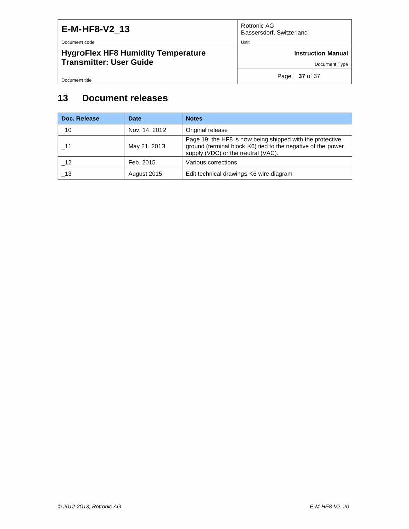
13 Document releases
Doc. Release Date Notes
_10 Nov. 14, 2012 Original release
_11 May 21, 2013 Page 19: the HF8 is now being shipped with the protective ground (terminal block K6) tied to the negative of the power supply (VDC) or the neutral (VAC).
_12 Feb. 2015 Various corrections
_13 August 2015 Edit technical drawings K6 wire diagram
© 2012-2013; Rotronic AG E-M-HF8-V2_20