Embed Size (px)
Citation preview
NUMBER 49, WINTER 1999–2000
Summaries of articles in this issue; mast. . . . . . . . . . . . . . . 2Contributions to Human Power . . . . . . . . . . . . . . . . . . . . . . 7
ArticlesVelocar variations
Arnfried Schmitz . . . . . . . . . . . . . . . . . . . . . . . . . . . . . . . . . 3Generators for bicycle lighting
Frank Krygowski and Don Slanina . . . . . . . . . . . . . . . . . 7Direct-drive (chainless) recumbent bicycles
Thomas Kretschmer . . . . . . . . . . . . . . . . . . . . . . . . . . . . . 11Cycle rickshaws as a sustainable transport system
for developing countriesAnil K. Rajvanshi . . . . . . . . . . . . . . . . . . . . . . . . . . . . . . . 15
Is the .deciMach Prize attainable?Michael Eliasohn . . . . . . . . . . . . . . . . . . . . . . . . . . . . . . . . 18
Technical notesBody shapes and influence of wind
Matt Weaver . . . . . . . . . . . . . . . . . . . . . . . . . . . . . . . . . . . . 21
LettersThe Rohloff 14-speed hub, Ian Sims . . . . . . . . . . . . . . . . . . 6Comments on abstracts of Too’s data
Raoul Reiser . . . . . . . . . . . . . . . . . . . . . . . . . . . . . . . . . . . . 24 Relations with the UCI, Peter Ross. . . . . . . . . . . . . . . . . . . 25 Greetings from Alaska, Smiley Shields . . . . . . . . . . . . . . . 25 Greetings from Sri Lanka, Ray Wijewardene . . . . . . . . . 26
EditorialsBouncing off the mainstream, Theo Schmidt . . . . . . . . . . 27Uncomfortable suits, Dave Wilson . . . . . . . . . . . . . . . . . . . 27
Number 49Winter 1999–2000 $5.50
TECHNICAL JOURNAL OF THE IHPVA
HUMANPOWER
A STRETCHED VELOCARMy son and I wanted to try out the
bicycle, but our legs were at least 100-mm too long for comfortable pedalling.So serious testing was not possible, butI had a nice machine to look at. In 1989
Human Power Number 49, winter 1999–2000 3
INTRODUCTION
Velocars were the unusual bikes thatset world records in the 1930s. They
were banned from regular racingbecause they were faster than tradition-al racing bikes. Apart from the 1984“Moserbike”, the 1992 OlympicBoardman bike, and the Graeme Obreemachines, no revolutionary bicycle hasachieved that distinction.
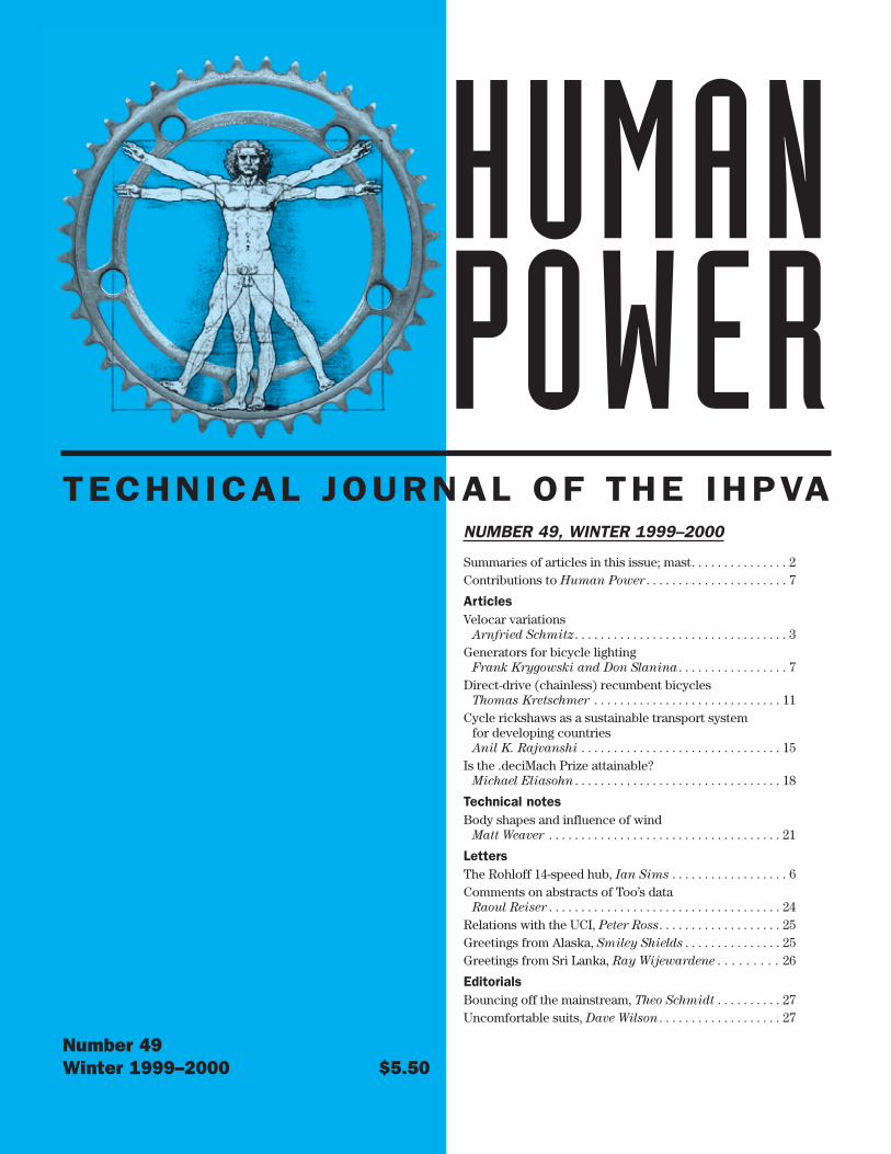
Charles Mochet, inventor and builderof the Velocar, made only one record-setting bicycle because his only goalwas that it be short enough to be with-in the UCI regulations of the time: themaximum length was set at 2 m. Heachieved this by reversing the frontfork. I wanted to make a replica, andCharles’ son Georges drew a set ofblueprints for me. The advantages ofthe design are evident from the oldpress photos (figure 1). The rider, whofor the 1933 records was Francis Faure,is seated as if in a deck-chair. His headis in a normal position, giving him agood view. His arms are along his bodyand fall naturally on the handlebars,just above his hips. Therefore his legshave no restrictions to movement andare supported from his back, which inturn is cradled on a long seat and back-rest. He can push higher gears and haslower drag because of the low frontalarea [and the fact that his legs are inthe front “shadow” of his body —ed.].The two 20" wheels have lower weightand lower aerodynamic drag than donormal-size wheels. My hobby: buildingnew types of bicycles. Building “future-bikes” often happens without formaldesigning and calculations. I start with,sometimes, a small concept. Ideascome as tubes are brazed together andthe wheels fitted. Giving the chain afree run is often a puzzle. Georgeslaughs “Your bike-building is an adven-ture!” I like to experience the develop-ment in full realism of my ideas. Ineighteen years I have built a lot ofbikes, with none turning out exactly asI had expected. I like the buildingwork: it’s exciting!
2 Number 49, winter 1999–2000 Human Power
HUMAN POWERHUMAN POWERis the technical journal of theInternational Human Powered VehicleAssociationNumber 49, Winter 1999–2000EditorDavid Gordon Wilson21 Winthrop StreetWinchester, MA 01890-2851 [email protected]
Associate editorsToshio Kataoka, Japan1-7-2-818 Hiranomiya-MachiHirano-ku, Osaka-shi, Japan [email protected]
Theodor Schmidt, EuropeOrtbühlweg 44CH-3612 Steffisburg, [email protected]
Philip Thiel, Watercraft4720 - 7th Avenue, NESeattle, WA 98105 USA
ProductionJS Design & JW Stephens
IHPVAPaul MacCready, Honorary presidentChris Broome, USA, ChairBen Wichers Schreur, The Netherlands,
Vice-chair,Jean Seay, Secretary/treasurer
PublisherIHPVAPO Box 1307 San Luis Obispo, CA 93406-1307 USAPhone: +805-545-9003; [email protected]
Human Power (ISSN 0898-6908) ispublished irregularly, ideally quarterly,for the International Human PoweredVehicle Association, an organizationdedicated to promoting improvement,innovation and creativity in the use ofhuman power generally, and especiallyin the design and development ofhuman-powered vehicles.
Material in Human Power is copyright-ed by the IHPVA. Unless copyrightedalso by the author(s), complete arti-cles or representative excerpts maybe published elsewhere if full credit isgiven prominently to the author(s) andthe IHPVA. Individual subscriptions areavailable to non-IHPVA or HPVA mem-bers, as are individual issues.
THE VELOCAR REPLICAWhen I build a bike for Georges I try
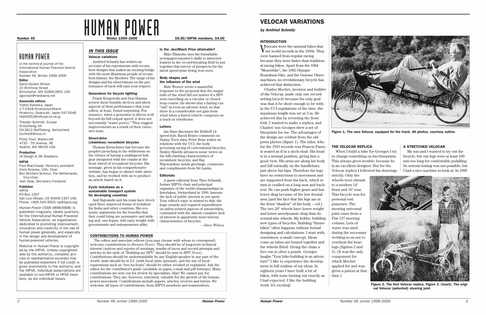
to change something on his blueprints.This always gives trouble, because heis an excellent designer. But for theVelocar replica I followed his drawingsstrictly. Only thewheels were shrunkto a modern 14"front and 16" rear.This bicycle was forpersonal testpurposes. Thesteering universaljoint came from aFiat 127 steeringcolumn. Lots ofwater was usedduring the necessarywelding so as not tooverheat the bear-ings (figures 2 and3). (It was the onlycomponent forwhich Mochetapplied for and wasgiven a patent at thattime.)
Number 49 Winter 1999–2000 $5.50/IHPVA members, $4.00
IN THIS ISSUEVelocar variations
Arnfried Schmitz has written anaccount of his experiments with recum-bent designs that makes an exciting bridgewith the most illustrious people of recum-bent history: the Mochets. The range of hisdesigns and his observations on the per-formance of each will earn your respect.
Generators for bicycle lightingFrank Krygowski and Don Slanina
review these humble devices and showaspects of their performance that youreditor, at least, found surprising. Forinstance, when a generator is driven wellbeyond its full-output speed, it does notnecessarily “waste power.” They suggestimprovements as a result of their exten-sive tests.
Direct-drive (chainless) recumbent bicycles
Thomas Kretschmer has become theprophet preaching in the wilderness onthe virtues of having a multispeed hubgear integrated with the cranks in thefront wheel of recumbent bicycles. Hismessage, given in his comprehensivewebsite, has begun to attract wide atten-tion, and he worked with us to producean article based on it.
Cycle rickshaws as a sustainable transport system for developing countries
Anil Rajvanshi and his team have devel-oped three improved forms of rickshawfor India and other countries. His eco-nomic arguments for the benefits thatthey could bring are persuasive and strik-ing and, one hopes, will carry weight withgovernments and entrepreneurs alike.
Is the .deciMach Prize attainable?Mike Eliasohn uses his formidable
newspaper-reporter’s skills to interviewleaders in the record-breaking field to puttogether this survey of prospects for thelatest speed prize being won soon.
Body shapes and the influence of the wind
Matt Weaver wrote a masterfulresponse to the proposal that the magni-tude of the wind did not matter if a HPVwere travelling on a circular or closed-loop course. He shows that a fairing can“sail” in even an adverse wind, so thatthere is a considerable net gain fromwind when a faired vehicle competes ona track or velodrome.
LettersIan Sims discusses the Rohloff 14-
speed hub; Raoul Reiser comments onDanny Too’s data; Peter Ross writes onrelations with the UCI, the bodygoverning racing of conventional bicycles;Smiley Shields advances some views onthe hill-climbing characteristics ofrecumbent bicycles; and RayWijewardene sends greetings, commentsand compliments from Sri Lanka.
EditorialsA guest editorial from Theo Schmidt,
former IHPVA chair and principalorganizer of the world championships inInterlaken, Switzerland in 1999, lamentsthe lack of public interest in our sport.Your editor’s topic is related to this: thehuge awards and required expenditureson safety-related aspects of automobiles,contrasted with the almost complete lackof interest in apparently more-seriouscharacteristics of bicycles.
—Dave Wilson
VELOCAR VARIATIONSby Arnfried Schmitz
Figure 1. The race Velocar, equipped for the track. All photos, courtesy author.
Figure 2. The first Velocar replica. Figure 3. (Inset). The origi-nal Velocar (patented) steering joint
CONTRIBUTIONS TO HUMAN POWERThe editor and associate editors (you may choose with whom to correspond)
welcome contributions to Human Power. They should be of long-term technicalinterest (notices and reports of meetings, results of races and record attempts andarticles in the style of “Building my HPV” should be sent to HPV News).Contributions should be understandable by any English-speaker in any part of theworld: units should be in S.I. (with local units optional), and the use of localexpressions such as “two-by-fours” should be either avoided or explained. Ask theeditor for the contributor’s guide (available in paper, e-mail and pdf formats). Manycontributions are sent out for review by specialists. Alas! We cannot pay forcontributions. They are, however, extremely valuable for the growth of the human-power movement. Contributions include papers, articles, reviews and letters. Wewelcome all types of contributions, from IHPVA members and nonmembers.
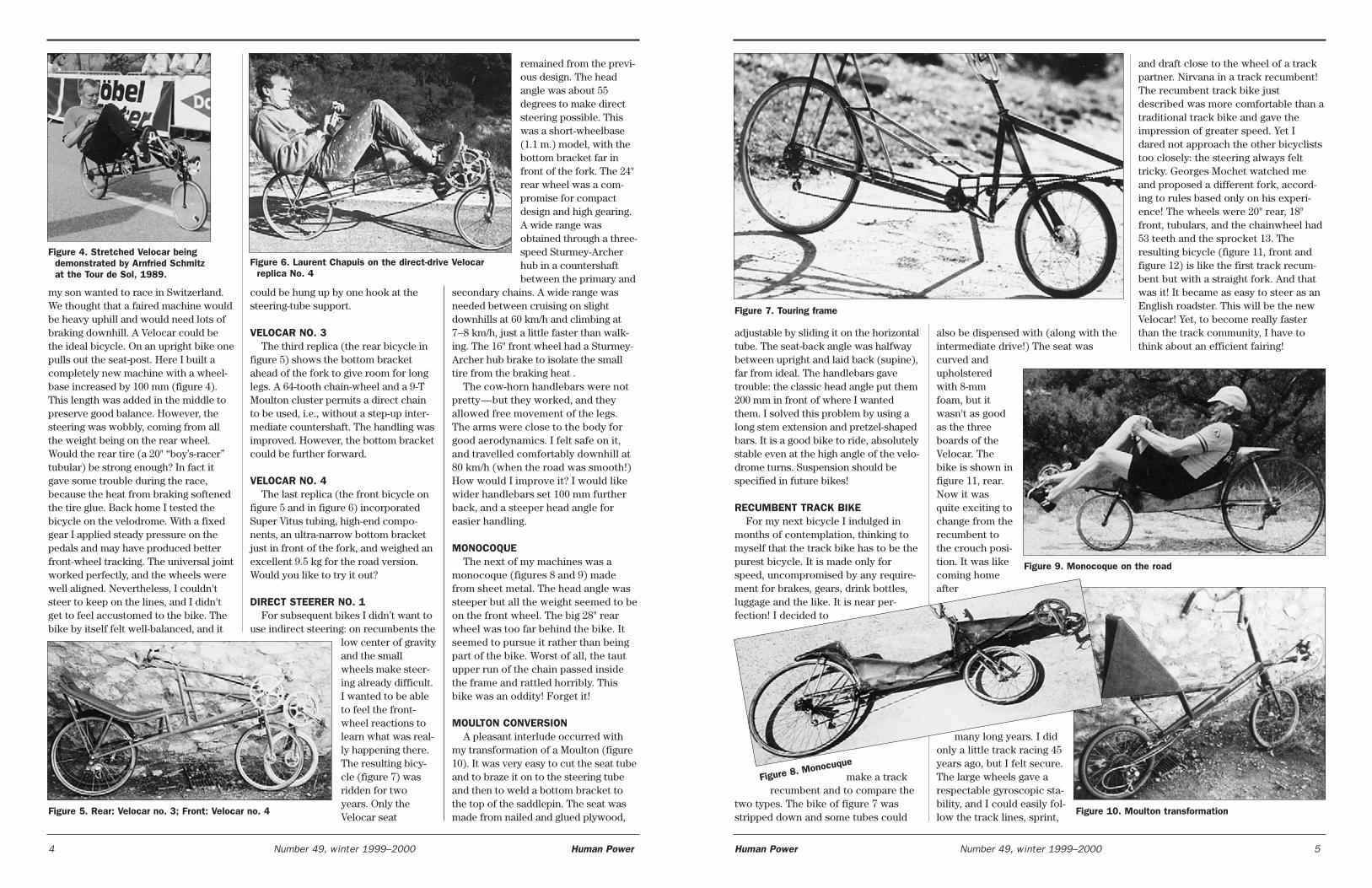
my son wanted to race in Switzerland.We thought that a faired machine wouldbe heavy uphill and would need lots ofbraking downhill. A Velocar could bethe ideal bicycle. On an upright bike onepulls out the seat-post. Here I built acompletely new machine with a wheel-base increased by 100 mm (figure 4).This length was added in the middle topreserve good balance. However, thesteering was wobbly, coming from allthe weight being on the rear wheel.Would the rear tire (a 20" “boy’s-racer”tubular) be strong enough? In fact itgave some trouble during the race,because the heat from braking softenedthe tire glue. Back home I tested thebicycle on the velodrome. With a fixedgear I applied steady pressure on thepedals and may have produced betterfront-wheel tracking. The universal jointworked perfectly, and the wheels werewell aligned. Nevertheless, I couldn'tsteer to keep on the lines, and I didn'tget to feel accustomed to the bike. Thebike by itself felt well-balanced, and it
could be hung up by one hook at thesteering-tube support.
VELOCAR NO. 3The third replica (the rear bicycle in
figure 5) shows the bottom bracketahead of the fork to give room for longlegs. A 64-tooth chain-wheel and a 9-TMoulton cluster permits a direct chainto be used, i.e., without a step-up inter-mediate countershaft. The handling wasimproved. However, the bottom bracketcould be further forward.
VELOCAR NO. 4The last replica (the front bicycle on
figure 5 and in figure 6) incorporatedSuper Vitus tubing, high-end compo-nents, an ultra-narrow bottom bracketjust in front of the fork, and weighed anexcellent 9.5 kg for the road version.Would you like to try it out?
DIRECT STEERER NO. 1For subsequent bikes I didn’t want to
use indirect steering: on recumbents thelow center of gravityand the smallwheels make steer-ing already difficult.I wanted to be ableto feel the front-wheel reactions tolearn what was real-ly happening there.The resulting bicy-cle (figure 7) wasridden for twoyears. Only theVelocar seat
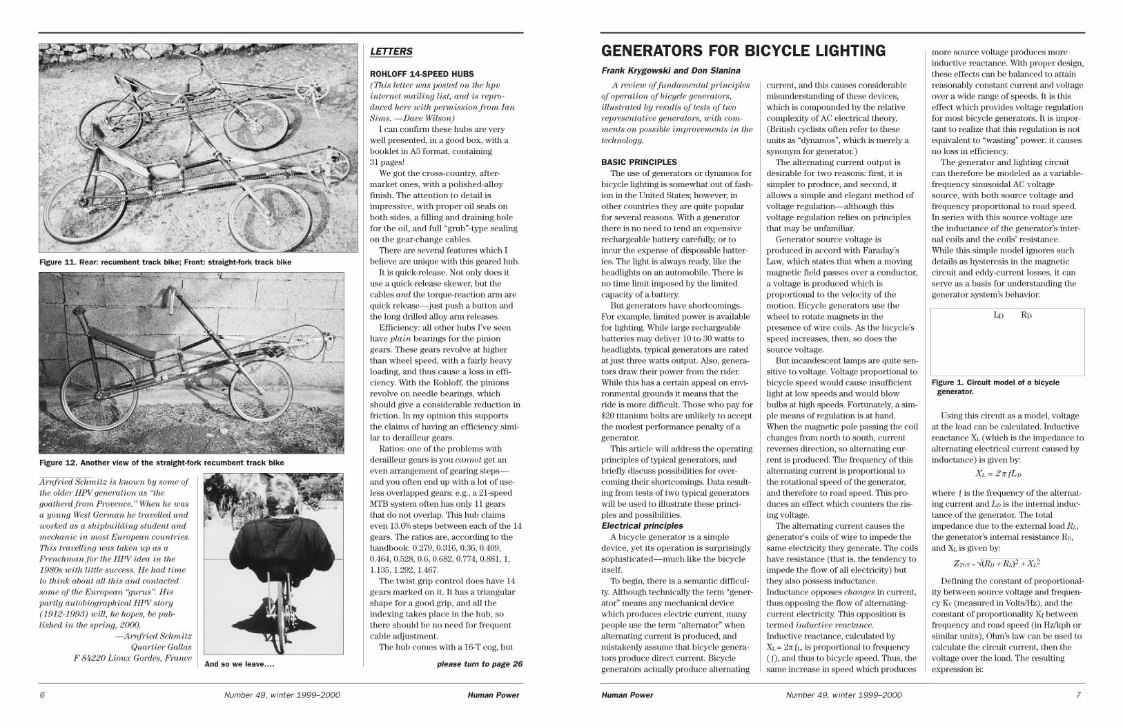
remained from the previ-ous design. The headangle was about 55degrees to make directsteering possible. Thiswas a short-wheelbase(1.1 m.) model, with thebottom bracket far infront of the fork. The 24"rear wheel was a com-promise for compactdesign and high gearing.A wide range wasobtained through a three-speed Sturmey-Archerhub in a countershaftbetween the primary and
secondary chains. A wide range wasneeded between cruising on slightdownhills at 60 km/h and climbing at7–8 km/h, just a little faster than walk-ing. The 16" front wheel had a Sturmey-Archer hub brake to isolate the smalltire from the braking heat .
The cow-horn handlebars were notpretty—but they worked, and theyallowed free movement of the legs.The arms were close to the body forgood aerodynamics. I felt safe on it,and travelled comfortably downhill at80 km/h (when the road was smooth!)How would I improve it? I would likewider handlebars set 100 mm furtherback, and a steeper head angle foreasier handling.
MONOCOQUEThe next of my machines was a
monocoque (figures 8 and 9) madefrom sheet metal. The head angle wassteeper but all the weight seemed to beon the front wheel. The big 28" rearwheel was too far behind the bike. Itseemed to pursue it rather than beingpart of the bike. Worst of all, the tautupper run of the chain passed insidethe frame and rattled horribly. Thisbike was an oddity! Forget it!
MOULTON CONVERSIONA pleasant interlude occurred with
my transformation of a Moulton (figure10). It was very easy to cut the seat tubeand to braze it on to the steering tubeand then to weld a bottom bracket tothe top of the saddlepin. The seat wasmade from nailed and glued plywood,
4 Number 49, winter 1999–2000 Human Power
adjustable by sliding it on the horizontaltube. The seat-back angle was halfwaybetween upright and laid back (supine),far from ideal. The handlebars gavetrouble: the classic head angle put them200 mm in front of where I wantedthem. I solved this problem by using along stem extension and pretzel-shapedbars. It is a good bike to ride, absolutelystable even at the high angle of the velo-drome turns. Suspension should bespecified in future bikes!
RECUMBENT TRACK BIKEFor my next bicycle I indulged in
months of contemplation, thinking tomyself that the track bike has to be thepurest bicycle. It is made only forspeed, uncompromised by any require-ment for brakes, gears, drink bottles,luggage and the like. It is near per-fection! I decided to
make a trackrecumbent and to compare the
two types. The bike of figure 7 wasstripped down and some tubes could
also be dispensed with (along with theintermediate drive!) The seat wascurved andupholsteredwith 8-mmfoam, but itwasn't as goodas the threeboards of theVelocar. Thebike is shown infigure 11, rear.Now it wasquite exciting tochange from therecumbent tothe crouch posi-tion. It was likecoming homeafter
many long years. I didonly a little track racing 45years ago, but I felt secure.The large wheels gave arespectable gyroscopic sta-bility, and I could easily fol-low the track lines, sprint,
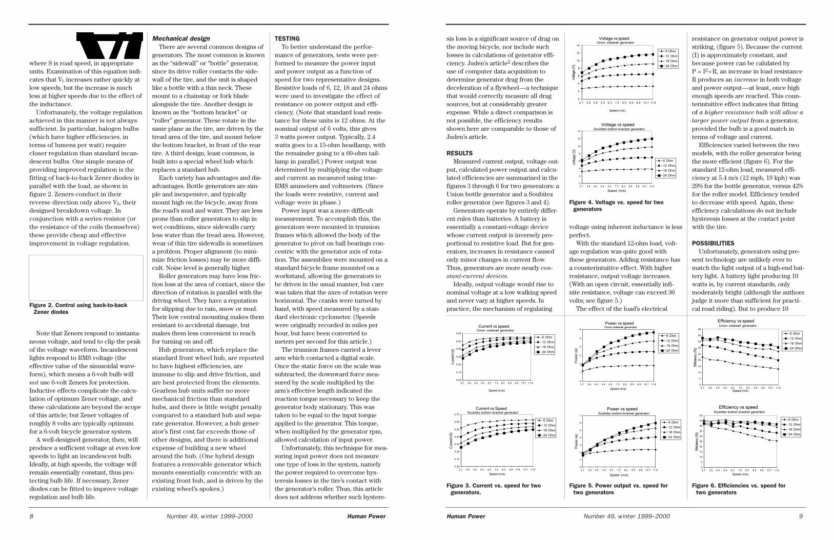
and draft close to the wheel of a trackpartner. Nirvana in a track recumbent!The recumbent track bike justdescribed was more comfortable than atraditional track bike and gave theimpression of greater speed. Yet Idared not approach the other bicycliststoo closely: the steering always felttricky. Georges Mochet watched meand proposed a different fork, accord-ing to rules based only on his experi-ence! The wheels were 20" rear, 18"front, tubulars, and the chainwheel had53 teeth and the sprocket 13. Theresulting bicycle (figure 11, front andfigure 12) is like the first track recum-bent but with a straight fork. And thatwas it! It became as easy to steer as anEnglish roadster. This will be the newVelocar! Yet, to become really fasterthan the track community, I have tothink about an efficient fairing!
Human Power Number 49, winter 1999–2000 5
Figure 5. Rear: Velocar no. 3; Front: Velocar no. 4
Figure 6. Laurent Chapuis on the direct-drive Velocar replica No. 4
Figure 9. Monocoque on the road
Figure 10. Moulton transformation
Figure 7. Touring frame
Figure 8. Monocuque
Figure 4. Stretched Velocar beingdemonstrated by Arnfried Schmitzat the Tour de Sol, 1989.
Arnfried Schmitz is known by some of
the older HPV generation as “the
goatherd from Provence.” When he was
a young West German he travelled and
worked as a shipbuilding student and
mechanic in most European countries.
This travelling was taken up as a
Frenchman for the HPV idea in the
1980s with little success. He had time
to think about all this and contacted
some of the European “gurus”. His
partly autobiographical HPV story
(1912-1993) will, he hopes, be pub-
lished in the spring, 2000.
—Arnfried Schmitz
Quartier Gallas
F 84220 Lioux Gordes, France
LETTERS
ROHLOFF 14-SPEED HUBS(This letter was posted on the hpv
internet mailing list, and is repro-
duced here with permission from Ian
Sims. —Dave Wilson)
I can confirm these hubs are verywell presented, in a good box, with abooklet in A5 format, containing31 pages!
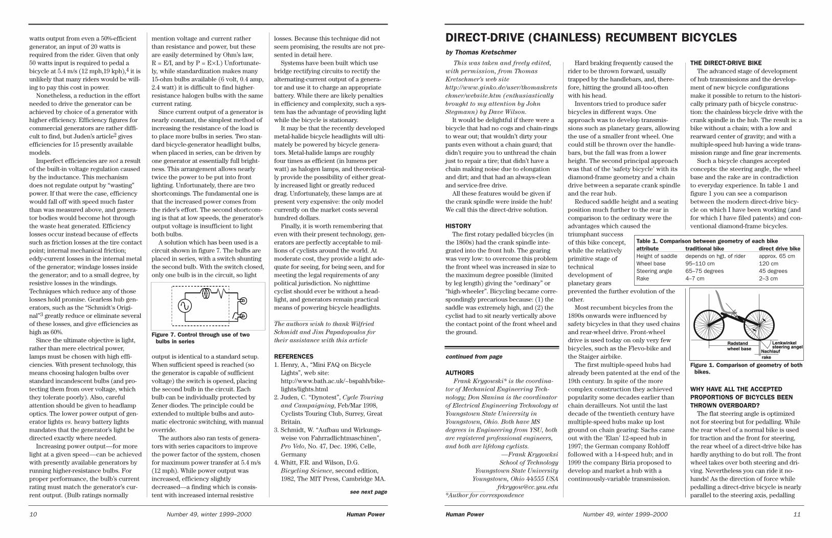
We got the cross-country, after-market ones, with a polished-alloyfinish. The attention to detail isimpressive, with proper oil seals onboth sides, a filling and draining holefor the oil, and full “grub”-type sealingon the gear-change cables.
There are several features which Ibelieve are unique with this geared hub.
It is quick-release. Not only does ituse a quick-release skewer, but thecables and the torque-reaction arm arequick release—just push a button andthe long drilled alloy arm releases.
Efficiency: all other hubs I’ve seenhave plain bearings for the piniongears. These gears revolve at higherthan wheel speed, with a fairly heavyloading, and thus cause a loss in effi-ciency. With the Rohloff, the pinionsrevolve on needle bearings, whichshould give a considerable reduction infriction. In my opinion this supportsthe claims of having an efficiency simi-lar to derailleur gears.
Ratios: one of the problems withderailleur gears is you cannot get aneven arrangement of gearing steps—and you often end up with a lot of use-less overlapped gears: e.g., a 21-speedMTB system often has only 11 gearsthat do not overlap. This hub claimseven 13.6% steps between each of the 14gears. The ratios are, according to thehandbook: 0.279, 0.316, 0.36, 0.409,0.464, 0.528, 0.6, 0.682, 0.774, 0.881, 1,1.135, 1.292, 1.467.
The twist grip control does have 14gears marked on it. It has a triangularshape for a good grip, and all theindexing takes place in the hub, sothere should be no need for frequentcable adjustment.
The hub comes with a 16-T cog, but
6 Number 49, winter 1999–2000 Human Power
A review of fundamental principles
of operation of bicycle generators,
illustrated by results of tests of two
representative generators, with com-
ments on possible improvements in the
technology.
BASIC PRINCIPLESThe use of generators or dynamos for
bicycle lighting is somewhat out of fash-ion in the United States; however, inother countries they are quite popularfor several reasons. With a generatorthere is no need to tend an expensiverechargeable battery carefully, or toincur the expense of disposable batter-ies. The light is always ready, like theheadlights on an automobile. There isno time limit imposed by the limitedcapacity of a battery.
But generators have shortcomings.For example, limited power is availablefor lighting. While large rechargeablebatteries may deliver 10 to 30 watts toheadlights, typical generators are ratedat just three watts output. Also, genera-tors draw their power from the rider.While this has a certain appeal on envi-ronmental grounds it means that theride is more difficult. Those who pay for$20 titanium bolts are unlikely to acceptthe modest performance penalty of agenerator.
This article will address the operatingprinciples of typical generators, andbriefly discuss possibilities for over-coming their shortcomings. Data result-ing from tests of two typical generatorswill be used to illustrate these princi-ples and possibilities.Electrical principles
A bicycle generator is a simpledevice, yet its operation is surprisinglysophisticated—much like the bicycleitself.
To begin, there is a semantic difficul-ty. Although technically the term “gener-ator” means any mechanical devicewhich produces electric current, manypeople use the term “alternator” whenalternating current is produced, andmistakenly assume that bicycle genera-tors produce direct current. Bicyclegenerators actually produce alternating
current, and this causes considerablemisunderstanding of these devices,which is compounded by the relativecomplexity of AC electrical theory.(British cyclists often refer to theseunits as “dynamos”, which is merely asynonym for generator.)
The alternating current output isdesirable for two reasons: first, it issimpler to produce, and second, itallows a simple and elegant method ofvoltage regulation—although thisvoltage regulation relies on principlesthat may be unfamiliar.
Generator source voltage isproduced in accord with Faraday’sLaw, which states that when a movingmagnetic field passes over a conductor,a voltage is produced which isproportional to the velocity of themotion. Bicycle generators use thewheel to rotate magnets in thepresence of wire coils. As the bicycle’sspeed increases, then, so does thesource voltage.
But incandescent lamps are quite sen-sitive to voltage. Voltage proportional tobicycle speed would cause insufficientlight at low speeds and would blowbulbs at high speeds. Fortunately, a sim-ple means of regulation is at hand.When the magnetic pole passing the coilchanges from north to south, currentreverses direction, so alternating cur-rent is produced. The frequency of thisalternating current is proportional tothe rotational speed of the generator,and therefore to road speed. This pro-duces an effect which counters the ris-ing voltage.
The alternating current causes thegenerator's coils of wire to impede thesame electricity they generate. The coilshave resistance (that is, the tendency toimpede the flow of all electricity) butthey also possess inductance.Inductance opposes changes in current,thus opposing the flow of alternating-current electricity. This opposition istermed inductive reactance.Inductive reactance, calculated byXL = 2��L, is proportional to frequency(�), and thus to bicycle speed. Thus, thesame increase in speed which produces
Human Power Number 49, winter 1999–2000 7
more source voltage produces moreinductive reactance. With proper design,these effects can be balanced to attainreasonably constant current and voltageover a wide range of speeds. It is thiseffect which provides voltage regulationfor most bicycle generators. It is impor-tant to realize that this regulation is notequivalent to “wasting” power: it causesno loss in efficiency.
The generator and lighting circuitcan therefore be modeled as a variable-frequency sinusoidal AC voltagesource, with both source voltage andfrequency proportional to road speed.In series with this source voltage arethe inductance of the generator’s inter-nal coils and the coils’ resistance.While this simple model ignores suchdetails as hysteresis in the magneticcircuit and eddy-current losses, it canserve as a basis for understanding thegenerator system’s behavior.
Using this circuit as a model, voltageat the load can be calculated. Inductivereactance XL (which is the impedance toalternating electrical current caused byinductance) is given by:
XL = 2��LD
where � is the frequency of the alternat-ing current and LD is the internal induc-tance of the generator. The totalimpedance due to the external load RL,the generator’s internal resistance RD,and XL is given by:
ZTOT = ��RD � RL�� � XL�
Defining the constant of proportional-ity between source voltage and frequen-cy KV (measured in Volts/Hz), and theconstant of proportionality Kf betweenfrequency and road speed (in Hz/kph orsimilar units), Ohm’s law can be used tocalculate the circuit current, then thevoltage over the load. The resultingexpression is:
And so we leave….
Figure 11. Rear: recumbent track bike; Front: straight-fork track bike
Figure 12. Another view of the straight-fork recumbent track bike
Figure 1. Circuit model of a bicycle generator.
GENERATORS FOR BICYCLE LIGHTINGFrank Krygowski and Don Slanina
LD RD
please turn to page 26
where S is road speed, in appropriateunits. Examination of this equation indi-cates that VL increases rather quickly atlow speeds, but the increase is muchless at higher speeds due to the effect ofthe inductance.
Unfortunately, the voltage regulationachieved in this manner is not alwayssufficient. In particular, halogen bulbs(which have higher efficiencies, interms of lumens per watt) requirecloser regulation than standard incan-descent bulbs. One simple means ofproviding improved regulation is thefitting of back-to-back Zener diodes inparallel with the load, as shown infigure 2. Zeners conduct in theirreverse direction only above VZ, theirdesigned breakdown voltage. Inconjunction with a series resistor (orthe resistance of the coils themselves)these provide cheap and effectiveimprovement in voltage regulation.
Note that Zeners respond to instanta-neous voltage, and tend to clip the peakof the voltage waveform. Incandescentlights respond to RMS voltage (theeffective value of the sinusoidal wave-form), which means a 6-volt bulb willnot use 6-volt Zeners for protection.Inductive effects complicate the calcu-lation of optimum Zener voltage, andthese calculations are beyond the scopeof this article; but Zener voltages ofroughly 8 volts are typically optimumfor a 6-volt bicycle generator system.
A well-designed generator, then, willproduce a sufficient voltage at even lowspeeds to light an incandescent bulb.Ideally, at high speeds, the voltage willremain essentially constant, thus pro-tecting bulb life. If necessary, Zenerdiodes can be fitted to improve voltageregulation and bulb life.
Mechanical designThere are several common designs of
generators. The most common is knownas the “sidewall” or “bottle” generator,since its drive roller contacts the side-wall of the tire, and the unit is shapedlike a bottle with a thin neck. Thesemount to a chainstay or fork bladealongside the tire. Another design isknown as the “bottom bracket” or“roller” generator. These rotate in thesame plane as the tire, are driven by thetread area of the tire, and mount belowthe bottom bracket, in front of the reartire. A third design, least common, isbuilt into a special wheel hub whichreplaces a standard hub.
Each variety has advantages and dis-advantages. Bottle generators are sim-ple and inexpensive, and typicallymount high on the bicycle, away fromthe road’s mud and water. They are lessprone than roller generators to slip inwet conditions, since sidewalls carryless water than the tread area. However,wear of thin tire sidewalls is sometimesa problem. Proper alignment (to mini-mize friction losses) may be more diffi-cult. Noise level is generally higher.
Roller generators may have less fric-tion loss at the area of contact, since thedirection of rotation is parallel with thedriving wheel. They have a reputationfor slipping due to rain, snow or mud.Their low central mounting makes themresistant to accidental damage, butmakes them less convenient to reachfor turning on and off.
Hub generators, which replace thestandard front wheel hub, are reportedto have highest efficiencies, areimmune to slip and drive friction, andare best protected from the elements.Gearless hub units suffer no moremechanical friction than standardhubs, and there is little weight penaltycompared to a standard hub and sepa-rate generator. However, a hub gener-ator’s first cost far exceeds those ofother designs, and there is additionalexpense of building a new wheelaround the hub. (One hybrid designfeatures a removable generator whichmounts essentially concentric with anexisting front hub, and is driven by theexisting wheel’s spokes.)
TESTINGTo better understand the perfor-
mance of generators, tests were per-formed to measure the power inputand power output as a function ofspeed for two representative designs.Resistive loads of 6, 12, 18 and 24 ohmswere used to investigate the effect ofresistance on power output and effi-ciency. (Note that standard load resis-tance for these units is 12 ohms. At thenominal output of 6 volts, this gives3 watts power output. Typically, 2.4watts goes to a 15-ohm headlamp, withthe remainder going to a 60-ohm tail-lamp in parallel.) Power output wasdetermined by multiplying the voltageand current as measured using true-RMS ammeters and voltmeters. (Sincethe loads were resistive, current andvoltage were in phase.)
Power input was a more difficultmeasurement. To accomplish this, thegenerators were mounted in trunnionframes which allowed the body of thegenerator to pivot on ball bearings con-centric with the generator axis of rota-tion. The assemblies were mounted on astandard bicycle frame mounted on aworkstand, allowing the generators tobe driven in the usual manner, but carewas taken that the axes of rotation werehorizontal. The cranks were turned byhand, with speed measured by a stan-dard electronic cyclometer. (Speedswere originally recorded in miles perhour, but have been converted tometers per second for this article.)
The trunnion frames carried a leverarm which contacted a digital scale.Once the static force on the scale wassubtracted, the downward force mea-sured by the scale multiplied by thearm’s effective length indicated thereaction torque necessary to keep thegenerator body stationary. This wastaken to be equal to the input torqueapplied to the generator. This torque,when multiplied by the generator rpm,allowed calculation of input power.
Unfortunately, this technique for mea-suring input power does not measureone type of loss in the system, namelythe power required to overcome hys-teresis losses in the tire’s contact withthe generator’s roller. Thus, this articledoes not address whether such hystere-
8 Number 49, winter 1999–2000 Human Power Human Power Number 49, winter 1999–2000 9
sis loss is a significant source of drag onthe moving bicycle, nor include suchlosses in calculations of generator effi-ciency. Juden’s article2 describes theuse of computer data acquisition todetermine generator drag from thedeceleration of a flywheel—a techniquethat would correctly measure all dragsources, but at considerably greaterexpense. While a direct comparison isnot possible, the efficiency resultsshown here are comparable to those ofJuden’s article.
RESULTSMeasured current output, voltage out-
put, calculated power output and calcu-lated efficiencies are summarized in thefigures 3 through 6 for two generators: aUnion bottle generator and a Soubitezroller generator (see figures 3 and 4).
Generators operate by entirely differ-ent rules than batteries. A battery isessentially a constant-voltage devicewhose current output is inversely pro-portional to resistive load. But for gen-erators, increases in resistance causedonly minor changes in current flow.Thus, generators are more nearly con-
stant-current devices. Ideally, output voltage would rise to
nominal voltage at a low walking speedand never vary at higher speeds. Inpractice, the mechanism of regulating
voltage using inherent inductance is lessperfect.
With the standard 12-ohm load, volt-age regulation was quite good withthese generators. Adding resistance hasa counterintuitive effect. With higherresistance, output voltage increases.(With an open circuit, essentially infi-nite resistance, voltage can exceed 30volts; see figure 5.)
The effect of the load’s electrical
resistance on generator output power isstriking, (figure 5). Because the current(I) is approximately constant, andbecause power can be calulated byP = I2�R, an increase in load resistanceR produces an increase in both voltageand power output—at least, once highenough speeds are reached. This coun-terintuitive effect indicates that fittingof a higher resistance bulb will allow a
larger power output from a generator,provided the bulb is a good match interms of voltage and current.
Efficiencies varied between the twomodels, with the roller generator beingthe more efficient (figure 6). For thestandard 12-ohm load, measured effi-ciency at 5.4 m/s (12 mph, 19 kph) was29% for the bottle generator, versus 42%for the roller model. Efficiency tendedto decrease with speed. Again, theseefficiency calculations do not includehysteresis losses at the contact pointwith the tire.
POSSIBILITIESUnfortunately, generators using pre-
sent technology are unlikely ever tomatch the light output of a high-end bat-tery light. A battery light producing 10watts is, by current standards, onlymoderately bright (although the authorsjudge it more than sufficient for practi-cal road riding). But to produce 10
Figure 2. Control using back-to-backZener diodes
��������������� ��� ����������������
����
����
����
����
����
����
����
��� ��� ��� ��� ��� ��� ��� ��� ��� ���� ����
������ !"
��$%
���$%
���$%
���$%
�����������������& ��'�&���� (&��)*������������
����
����
����
����
����
����
����
����
��� ��� ��� ��� ��� ��� ��� ��� ��� ���� ����
������ !"
��$%
���$%
���$%
���$%
Figure 3. Current vs. speed for two generators.
+���������������& ��'�&���� (&��)*������������
�
�
�
�
�
��
��
��
��� ��� ��� ��� ��� ��� ��� ��� ��� ���� ����
����� � !"
��$%
���$%
���$%
���$%
Figure 4. Voltage vs. speed for two generators
+�������������� ��� ������� ���������
�
�
�
�
�
��
��
��
��� ��� ��� ��� ��� ��� ��� ��� ��� ���� ����
������ !"
��$%
���$%
���$%
���$%
,�������������& ��'�&���� (&��)*������������
�
�
�
�
�
�
�
�
��� ��� ��� ��� ��� ��� ��� ��� ��� ���� ����
����� � !"
��$%
���$%
���$%
���$%
Figure 5. Power output vs. speed for two generators
,������������ ��� ����������������
�
�
�
�
�
�
�
��� ��� ��� ��� ��� ��� ��� ��� ��� ���� ����
������ !"
��$%
���$%
���$%
���$%
-.. ) ��)/���������& ��'�&���� (&��)*������������
�
�
��
��
��
��
��
��
��
��
��
��� ��� ��� ��� ��� ��� ��� ��� ��� ���� ����
������ !"
��$%
���$%
���$%
���$%
Figure 6. Efficiencies vs. speed for two generators
-.. ) ��)/�������� ��� ����������������
�
�
��
��
��
��
��
��
��
��
��� ��� ��� ��� ��� ��� ��� ��� ��� ���� ���������� !"
��$%
���$%
���$%
���$%
��
This was taken and freely edited,
with permission, from Thomas
Kretschmer’s web site
http://www.ginko.de/user/thomaskrets
chmer/website.htm (enthusiastically
brought to my attention by John
Stegmann) by Dave Wilson.
It would be delightful if there were abicycle that had no cogs and chain-ringsto wear out; that wouldn’t dirty yourpants even without a chain guard; thatdidn’t require you to unthread the chainjust to repair a tire; that didn’t have achain making noise due to elongationand dirt; and that had an always-cleanand service-free drive.
All these features would be given ifthe crank spindle were inside the hub!We call this the direct-drive solution.
HISTORYThe first rotary pedalled bicycles (in
the 1860s) had the crank spindle inte-grated into the front hub. The gearingwas very low: to overcome this problemthe front wheel was increased in size tothe maximum degree possible (limitedby leg length) giving the “ordinary” or“high-wheeler”. Bicycling became corre-spondingly precarious because: (1) thesaddle was extremely high, and (2) thecyclist had to sit nearly vertically abovethe contact point of the front wheel andthe ground.
Hard braking frequently caused therider to be thrown forward, usuallytrapped by the handlebars, and, there-fore, hitting the ground all-too-oftenwith his head.
Inventors tried to produce saferbicycles in different ways. Oneapproach was to develop transmis-sions such as planetary gears, allowingthe use of a smaller front wheel. Onecould still be thrown over the handle-bars, but the fall was from a lowerheight. The second principal approachwas that of the ‘safety bicycle’ with itsdiamond-frame geometry and a chaindrive between a separate crank spindleand the rear hub.
Reduced saddle height and a seatingposition much further to the rear incomparison to the ordinary were theadvantages which caused thetriumphant successof this bike concept,while the relativelyprimitive stage oftechnicaldevelopment ofplanetary gearsprevented the further evolution of theother.
Most recumbent bicycles from the1890s onwards were influenced bysafety bicycles in that they used chainsand rear-wheel drive. Front-wheeldrive is used today on only very fewbicycles, such as the Flevo-bike andthe Staiger airbike.
The first multiple-speed hubs hadalready been patented at the end of the19th century. In spite of the morecomplex construction they achievedpopularity some decades earlier thanchain derailleurs. Not until the lastdecade of the twentieth century havemultiple-speed hubs make up lostground on chain gearing: Sachs cameout with the ‘Elan’ 12-speed hub in1997; the German company Rohlofffollowed with a 14-speed hub; and in1999 the company Biria proposed todevelop and market a hub with acontinuously-variable transmission.
watts output from even a 50%-efficientgenerator, an input of 20 watts isrequired from the rider. Given that only50 watts input is required to pedal abicycle at 5.4 m/s (12 mph,19 kph),4 it isunlikely that many riders would be will-ing to pay this cost in power.
Nonetheless, a reduction in the effortneeded to drive the generator can beachieved by choice of a generator withhigher efficiency. Efficiency figures forcommercial generators are rather diffi-cult to find, but Juden’s article2 givesefficiencies for 15 presently availablemodels.
Imperfect efficiencies are not a resultof the built-in voltage regulation causedby the inductance. This mechanismdoes not regulate output by “wasting”power. If that were the case, efficiencywould fall off with speed much fasterthan was measured above, and genera-tor bodies would become hot throughthe waste heat generated. Efficiencylosses occur instead because of effectssuch as friction losses at the tire contactpoint; internal mechanical friction;eddy-current losses in the internal metalof the generator; windage losses insidethe generator; and to a small degree, byresistive losses in the windings.Techniques which reduce any of thoselosses hold promise. Gearless hub gen-erators, such as the “Schmidt's Origi-nal”3 greatly reduce or eliminate severalof these losses, and give efficiencies ashigh as 60%.
Since the ultimate objective is light,rather than mere electrical power,lamps must be chosen with high effi-ciencies. With present technology, thismeans choosing halogen bulbs overstandard incandescent bulbs (and pro-tecting them from over voltage, whichthey tolerate poorly). Also, carefulattention should be given to headlampoptics. The lower power output of gen-erator lights vs. heavy battery lightsmandates that the generator’s light bedirected exactly where needed.
Increasing power output—for morelight at a given speed—can be achievedwith presently available generators byrunning higher-resistance bulbs. Forproper performance, the bulb’s currentrating must match the generator’s cur-rent output. (Bulb ratings normally
mention voltage and current ratherthan resistance and power, but theseare easily determined by Ohm’s law,R = E/I, and by P = E×I.) Unfortunate-ly, while standardization makes many15-ohm bulbs available (6 volt, 0.4 amp,2.4 watt) it is difficult to find higher-resistance halogen bulbs with the samecurrent rating.
Since current output of a generator isnearly constant, the simplest method ofincreasing the resistance of the load isto place more bulbs in series. Two stan-dard bicycle-generator headlight bulbs,when placed in series, can be driven byone generator at essentially full bright-ness. This arrangement allows nearlytwice the power to be put into frontlighting. Unfortunately, there are twoshortcomings. The fundamental one isthat the increased power comes fromthe rider’s effort. The second shortcom-ing is that at low speeds, the generator’soutput voltage is insufficient to lightboth bulbs.
A solution which has been used is acircuit shown in figure 7. The bulbs areplaced in series, with a switch shuntingthe second bulb. With the switch closed,only one bulb is in the circuit, so light
output is identical to a standard setup.When sufficient speed is reached (sothe generator is capable of sufficientvoltage) the switch is opened, placingthe second bulb in the circuit. Eachbulb can be individually protected byZener diodes. The principle could beextended to multiple bulbs and auto-matic electronic switching, with manualoverride.
The authors also ran tests of genera-tors with series capacitors to improvethe power factor of the system, chosenfor maximum power transfer at 5.4 m/s(12 mph). While power output wasincreased, efficiency slightlydecreased—a finding which is consis-tent with increased internal resistive
losses. Because this technique did notseem promising, the results are not pre-sented in detail here.
Systems have been built which usebridge rectifying circuits to rectify thealternating-current output of a genera-tor and use it to charge an appropriatebattery. While there are likely penaltiesin efficiency and complexity, such a sys-tem has the advantage of providing lightwhile the bicycle is stationary.
It may be that the recently developedmetal-halide bicycle headlights will ulti-mately be powered by bicycle genera-tors. Metal-halide lamps are roughlyfour times as efficient (in lumens perwatt) as halogen lamps, and theoretical-ly provide the possibility of either great-ly increased light or greatly reduceddrag. Unfortunately, these lamps are atpresent very expensive: the only modelcurrently on the market costs severalhundred dollars.
Finally, it is worth remembering thateven with their present technology, gen-erators are perfectly acceptable to mil-lions of cyclists around the world. Atmoderate cost, they provide a light ade-quate for seeing, for being seen, and formeeting the legal requirements of anypolitical jurisdiction. No nighttimecyclist should ever be without a head-light, and generators remain practicalmeans of powering bicycle headlights.
The authors wish to thank Wilfried
Schmidt and Jim Papadopoulos for
their assistance with this article
REFERENCES1. Henry, A., “Mini FAQ on Bicycle
Lights”, web site:http://www.bath.ac.uk/~bspahh/bike-lights/lights.html
2. Juden, C. “Dynotest”, Cycle Touring
and Campaigning, Feb/Mar 1998,Cyclists Touring Club, Surrey, GreatBritain.
3. Schmidt, W. “Aufbau und Wirkungs-weise von Fahrradlichtmaschinen”,Pro Velo, No. 47, Dec. 1996, Celle,Germany
4. Whitt, F.R. and Wilson, D.G.Bicycling Science, second edition,1982, The MIT Press, Cambridge MA.
THE DIRECT-DRIVE BIKEThe advanced stage of development
of hub transmissions and the develop-ment of new bicycle configurationsmake it possible to return to the histori-cally primary path of bicycle construc-tion: the chainless bicycle drive with thecrank spindle in the hub. The result is: abike without a chain; with a low andrearward center of gravity; and with amultiple-speed hub having a wide trans-mission range and fine gear increments.
Such a bicycle changes acceptedconcepts: the steering angle, the wheelbase and the rake are in contradictionto everyday experience. In table 1 andfigure 1 you can see a comparisonbetween the modern direct-drive bicy-cle on which I have been working (andfor which I have filed patents) and con-ventional diamond-frame bicycles.
WHY HAVE ALL THE ACCEPTED PROPORTIONS OF BICYCLES BEENTHROWN OVERBOARD?
The flat steering angle is optimizednot for steering but for pedalling. Whilethe rear wheel of a normal bike is usedfor traction and the front for steering,the rear wheel of a direct-drive bike hashardly anything to do but roll. The frontwheel takes over both steering and dri-ving. Nevertheless you can ride it no-hands! As the direction of force whilepedalling a direct-drive bicycle is nearlyparallel to the steering axis, pedalling
Figure 7. Control through use of twobulbs in series
DIRECT-DRIVE (CHAINLESS) RECUMBENT BICYCLESby Thomas Kretschmer
Table 1. Comparison between geometry of each bikeattribute traditional bike direct drive bikeHeight of saddle depends on hgt. of rider approx. 65 cmWheel base 95–110 cm 120 cmSteering angle 65–75 degrees 45 degreesRake 4–7 cm 2–3 cm
AUTHORSFrank Krygowski* is the coordina-
tor of Mechanical Engineering Tech-
nology; Don Slanina is the coordinator
of Electrical Engineering Technology at
Youngstown State University in
Youngstown, Ohio. Both have MS
degrees in Engineering from YSU, both
are registered professional engineers,
and both are lifelong cyclists.
—Frank Krygowksi
School of Technology
Youngstown State University
Youngstown, Ohio 44555 USA
*Author for correspondence
continued from page
see next page
Lenkwinkelsteering angel
Nachlaufrake
Radstandwheel base
Figure 1. Comparison of geometry of bothbikes.
10 Number 49, winter 1999–2000 Human Power Human Power Number 49, winter 1999–2000 11
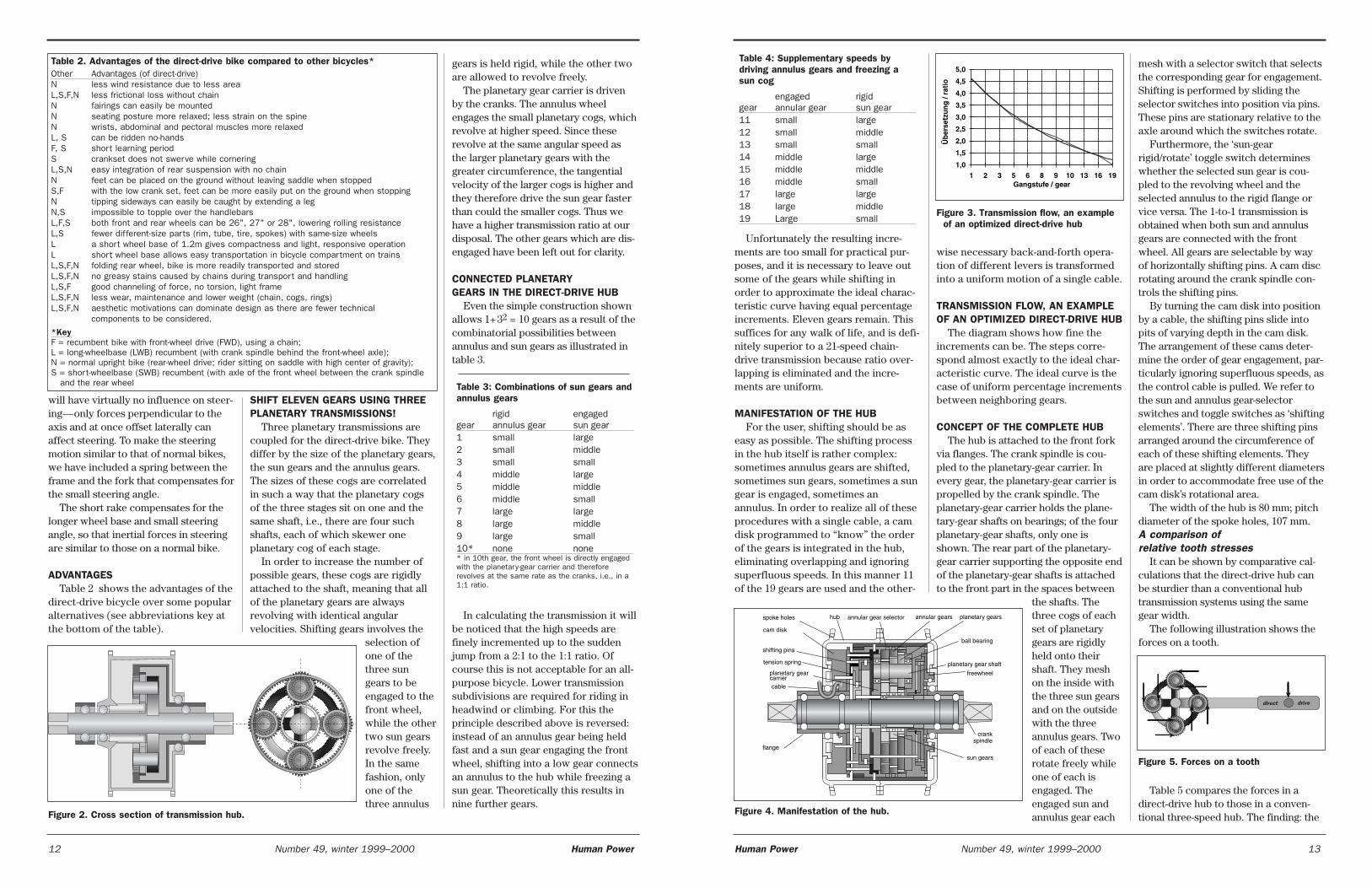
Table 4: Supplementary speeds by driving annulus gears and freezing asun cog
engaged rigidgear annular gear sun gear11 small large12 small middle13 small small14 middle large15 middle middle16 middle small17 large large18 large middle19 Large small
Unfortunately the resulting incre-ments are too small for practical pur-poses, and it is necessary to leave outsome of the gears while shifting inorder to approximate the ideal charac-teristic curve having equal percentageincrements. Eleven gears remain. Thissuffices for any walk of life, and is defi-nitely superior to a 21-speed chain-drive transmission because ratio over-lapping is eliminated and the incre-ments are uniform.
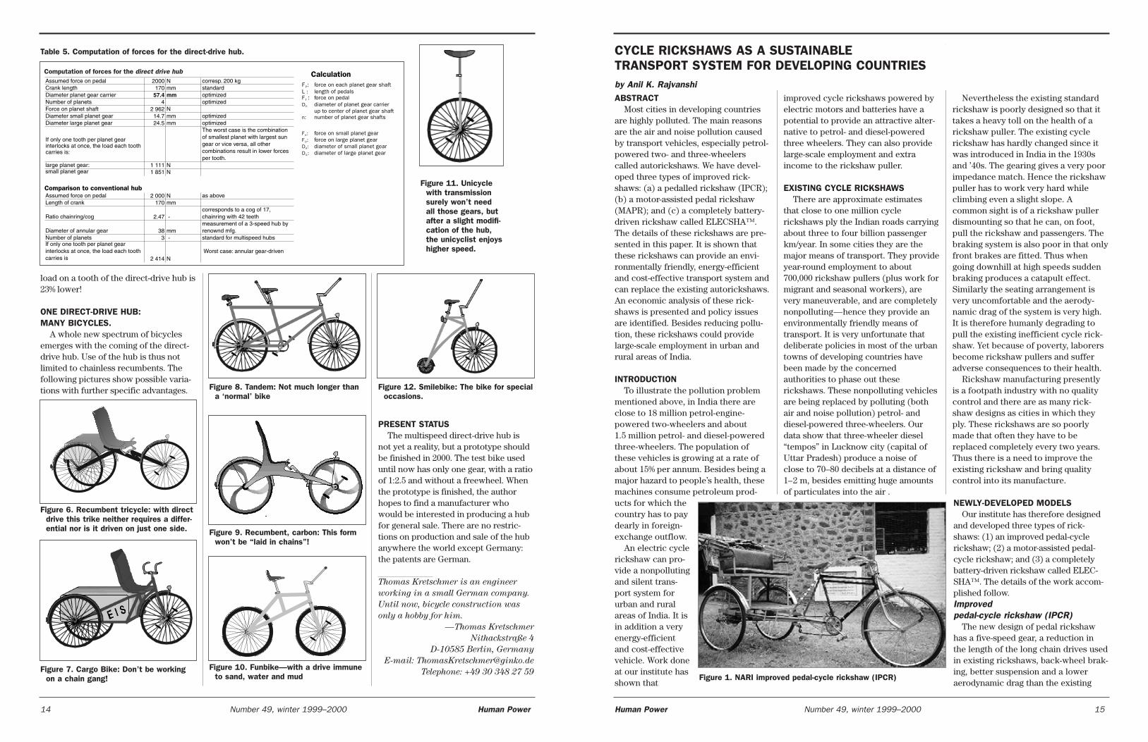
MANIFESTATION OF THE HUBFor the user, shifting should be as
easy as possible. The shifting processin the hub itself is rather complex:sometimes annulus gears are shifted,sometimes sun gears, sometimes a sungear is engaged, sometimes anannulus. In order to realize all of theseprocedures with a single cable, a camdisk programmed to “know” the orderof the gears is integrated in the hub,eliminating overlapping and ignoringsuperfluous speeds. In this manner 11of the 19 gears are used and the other-
gears is held rigid, while the other twoare allowed to revolve freely.
The planetary gear carrier is drivenby the cranks. The annulus wheelengages the small planetary cogs, whichrevolve at higher speed. Since theserevolve at the same angular speed asthe larger planetary gears with thegreater circumference, the tangentialvelocity of the larger cogs is higher andthey therefore drive the sun gear fasterthan could the smaller cogs. Thus wehave a higher transmission ratio at ourdisposal. The other gears which are dis-engaged have been left out for clarity.
CONNECTED PLANETARY GEARS IN THE DIRECT-DRIVE HUB
Even the simple construction shownallows 1+32 = 10 gears as a result of thecombinatorial possibilities betweenannulus and sun gears as illustrated intable 3.
Table 3: Combinations of sun gears andannulus gears
rigid engagedgear annulus gear sun gear1 small large2 small middle3 small small4 middle large5 middle middle6 middle small7 large large8 large middle9 large small10* none none* in 10th gear, the front wheel is directly engagedwith the planetary-gear carrier and thereforerevolves at the same rate as the cranks, i.e., in a1:1 ratio.
In calculating the transmission it willbe noticed that the high speeds arefinely incremented up to the suddenjump from a 2:1 to the 1:1 ratio. Ofcourse this is not acceptable for an all-purpose bicycle. Lower transmissionsubdivisions are required for riding inheadwind or climbing. For this theprinciple described above is reversed:instead of an annulus gear being heldfast and a sun gear engaging the frontwheel, shifting into a low gear connectsan annulus to the hub while freezing asun gear. Theoretically this results innine further gears.
wise necessary back-and-forth opera-tion of different levers is transformedinto a uniform motion of a single cable.
TRANSMISSION FLOW, AN EXAMPLEOF AN OPTIMIZED DIRECT-DRIVE HUB
The diagram shows how fine theincrements can be. The steps corre-spond almost exactly to the ideal char-acteristic curve. The ideal curve is thecase of uniform percentage incrementsbetween neighboring gears.
CONCEPT OF THE COMPLETE HUBThe hub is attached to the front fork
via flanges. The crank spindle is cou-pled to the planetary-gear carrier. Inevery gear, the planetary-gear carrier ispropelled by the crank spindle. Theplanetary-gear carrier holds the plane-tary-gear shafts on bearings; of the fourplanetary-gear shafts, only one isshown. The rear part of the planetary-gear carrier supporting the opposite endof the planetary-gear shafts is attachedto the front part in the spaces between
the shafts. Thethree cogs of eachset of planetarygears are rigidlyheld onto theirshaft. They meshon the inside withthe three sun gearsand on the outsidewith the threeannulus gears. Twoof each of theserotate freely whileone of each isengaged. Theengaged sun andannulus gear each
SHIFT ELEVEN GEARS USING THREEPLANETARY TRANSMISSIONS!
Three planetary transmissions arecoupled for the direct-drive bike. Theydiffer by the size of the planetary gears,the sun gears and the annulus gears.The sizes of these cogs are correlatedin such a way that the planetary cogsof the three stages sit on one and thesame shaft, i.e., there are four suchshafts, each of which skewer oneplanetary cog of each stage.
In order to increase the number ofpossible gears, these cogs are rigidlyattached to the shaft, meaning that allof the planetary gears are alwaysrevolving with identical angularvelocities. Shifting gears involves the
selection ofone of thethree sungears to beengaged to thefront wheel,while the othertwo sun gearsrevolve freely.In the samefashion, onlyone of thethree annulus
mesh with a selector switch that selectsthe corresponding gear for engagement.Shifting is performed by sliding theselector switches into position via pins.These pins are stationary relative to theaxle around which the switches rotate.
Furthermore, the ‘sun-gearrigid/rotate’ toggle switch determineswhether the selected sun gear is cou-pled to the revolving wheel and theselected annulus to the rigid flange orvice versa. The 1-to-1 transmission isobtained when both sun and annulusgears are connected with the frontwheel. All gears are selectable by wayof horizontally shifting pins. A cam discrotating around the crank spindle con-trols the shifting pins.
By turning the cam disk into positionby a cable, the shifting pins slide intopits of varying depth in the cam disk.The arrangement of these cams deter-mine the order of gear engagement, par-ticularly ignoring superfluous speeds, asthe control cable is pulled. We refer tothe sun and annulus gear-selectorswitches and toggle switches as ‘shiftingelements’. There are three shifting pinsarranged around the circumference ofeach of these shifting elements. Theyare placed at slightly different diametersin order to accommodate free use of thecam disk’s rotational area.
The width of the hub is 80 mm; pitchdiameter of the spoke holes, 107 mm.A comparison of relative tooth stresses
It can be shown by comparative cal-culations that the direct-drive hub canbe sturdier than a conventional hubtransmission systems using the samegear width.
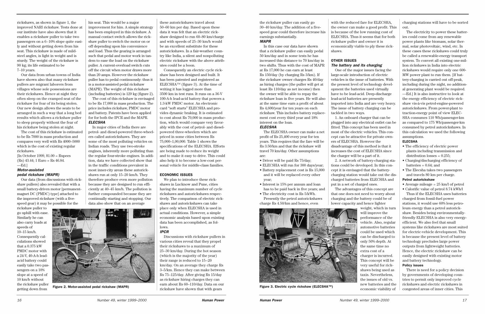
The following illustration shows theforces on a tooth.
Table 5 compares the forces in adirect-drive hub to those in a conven-tional three-speed hub. The finding: the
will have virtually no influence on steer-ing—only forces perpendicular to theaxis and at once offset laterally canaffect steering. To make the steeringmotion similar to that of normal bikes,we have included a spring between theframe and the fork that compensates forthe small steering angle.
The short rake compensates for thelonger wheel base and small steeringangle, so that inertial forces in steeringare similar to those on a normal bike.
ADVANTAGESTable 2 shows the advantages of the
direct-drive bicycle over some popularalternatives (see abbreviations key atthe bottom of the table).
Figure 2. Cross section of transmission hub.
1,0
1,5
2,0
2,5
3,0
3,5
4,0
4,5
5,0
1 2 3 5 6 8 9 10 13 16 19Gangstufe / gear
Üb
erse
tzu
ng
/ ra
tio
Figure 3. Transmission flow, an exampleof an optimized direct-drive hub
Table 2. Advantages of the direct-drive bike compared to other bicycles*Other Advantages (of direct-drive)N less wind resistance due to less area L,S,F,N less frictional loss without chain N fairings can easily be mountedN seating posture more relaxed; less strain on the spine N wrists, abdominal and pectoral muscles more relaxed L, S can be ridden no-handsF, S short learning periodS crankset does not swerve while cornering L,S,N easy integration of rear suspension with no chain N feet can be placed on the ground without leaving saddle when stopped S,F with the low crank set, feet can be more easily put on the ground when stoppingN tipping sideways can easily be caught by extending a leg N,S impossible to topple over the handlebarsL,F,S both front and rear wheels can be 26", 27" or 28", lowering rolling resistanceL,S fewer different-size parts (rim, tube, tire, spokes) with same-size wheelsL a short wheel base of 1.2m gives compactness and light, responsive operationL short wheel base allows easy transportation in bicycle compartment on trains L,S,F,N folding rear wheel, bike is more readily transported and stored L,S,F,N no greasy stains caused by chains during transport and handling L,S,F good channeling of force, no torsion, light frame L,S,F,N less wear, maintenance and lower weight (chain, cogs, rings) L,S,F,N aesthetic motivations can dominate design as there are fewer technical
components to be considered.
*KeyF = recumbent bike with front-wheel drive (FWD), using a chain; L = long-wheelbase (LWB) recumbent (with crank spindle behind the front-wheel axle); N = normal upright bike (rear-wheel drive; rider sitting on saddle with high center of gravity); S = short-wheelbase (SWB) recumbent (with axle of the front wheel between the crank spindle
and the rear wheel
direct drive
Figure 5. Forces on a tooth
tension spring
flange
planetary gear shaft
ball bearing
shifting pins
sun gears
crank spindle
planetary gear carrier
freewheel
cam disk
hub annular gear selector annular gears planetary gearsspoke holes
cable
Figure 4. Manifestation of the hub.
12 Number 49, winter 1999–2000 Human Power Human Power Number 49, winter 1999–2000 13
improved cycle rickshaws powered byelectric motors and batteries have apotential to provide an attractive alter-native to petrol- and diesel-poweredthree wheelers. They can also providelarge-scale employment and extraincome to the rickshaw puller.
EXISTING CYCLE RICKSHAWSThere are approximate estimates
that close to one million cyclerickshaws ply the Indian roads carryingabout three to four billion passengerkm/year. In some cities they are themajor means of transport. They provideyear-round employment to about700,000 rickshaw pullers (plus work formigrant and seasonal workers), arevery maneuverable, and are completelynonpolluting—hence they provide anenvironmentally friendly means oftransport. It is very unfortunate thatdeliberate policies in most of the urbantowns of developing countries havebeen made by the concernedauthorities to phase out theserickshaws. These nonpolluting vehiclesare being replaced by polluting (bothair and noise pollution) petrol- anddiesel-powered three-wheelers. Ourdata show that three-wheeler diesel“tempos” in Lucknow city (capital ofUttar Pradesh) produce a noise ofclose to 70–80 decibels at a distance of1–2 m, besides emitting huge amountsof particulates into the air .
ABSTRACTMost cities in developing countries
are highly polluted. The main reasonsare the air and noise pollution causedby transport vehicles, especially petrol-powered two- and three-wheelerscalled autorickshaws. We have devel-oped three types of improved rick-shaws: (a) a pedalled rickshaw (IPCR);(b) a motor-assisted pedal rickshaw(MAPR); and (c) a completely battery-driven rickshaw called ELECSHA™.The details of these rickshaws are pre-sented in this paper. It is shown thatthese rickshaws can provide an envi-ronmentally friendly, energy-efficientand cost-effective transport system andcan replace the existing autorickshaws.An economic analysis of these rick-shaws is presented and policy issuesare identified. Besides reducing pollu-tion, these rickshaws could providelarge-scale employment in urban andrural areas of India.
INTRODUCTIONTo illustrate the pollution problem
mentioned above, in India there areclose to 18 million petrol-engine-powered two-wheelers and about1.5 million petrol- and diesel-poweredthree-wheelers. The population ofthese vehicles is growing at a rate ofabout 15% per annum. Besides being amajor hazard to people’s health, thesemachines consume petroleum prod-ucts for which thecountry has to paydearly in foreign-exchange outflow.
An electric cyclerickshaw can pro-vide a nonpollutingand silent trans-port system forurban and ruralareas of India. It isin addition a veryenergy-efficientand cost-effectivevehicle. Work doneat our institute hasshown that
PRESENT STATUSThe multispeed direct-drive hub is
not yet a reality, but a prototype shouldbe finished in 2000. The test bike useduntil now has only one gear, with a ratioof 1:2.5 and without a freewheel. Whenthe prototype is finished, the authorhopes to find a manufacturer whowould be interested in producing a hubfor general sale. There are no restric-tions on production and sale of the hubanywhere the world except Germany:the patents are German.
Thomas Kretschmer is an engineer
working in a small German company.
Until now, bicycle construction was
only a hobby for him.
—Thomas Kretschmer
Nithackstraße 4
D-10585 Berlin, Germany
E-mail: [email protected]
Telephone: +49 30 348 27 59
load on a tooth of the direct-drive hub is23% lower!
ONE DIRECT-DRIVE HUB: MANY BICYCLES.
A whole new spectrum of bicyclesemerges with the coming of the direct-drive hub. Use of the hub is thus notlimited to chainless recumbents. Thefollowing pictures show possible varia-tions with further specific advantages.
Figure 9. Recumbent, carbon: This formwon’t be “laid in chains”!
Figure 6. Recumbent tricycle: with directdrive this trike neither requires a differ-ential nor is it driven on just one side.
Figure 10. Funbike—with a drive immuneto sand, water and mud
Assumed force on pedal 2000 N corresp. 200 kgCrank length 170 mm standardDiameter planet gear carrier 57.4 mm optimizedNumber of planets 4 optimizedForce on planet shaft 2 962 NDiameter small planet gear 14.7 mm optimizedDiameter large planet gear 24.5 mm optimized
If only one tooth per planet gearinterlocks at once, the load each toothcarries is:
The worst case is the combinationof smallest planet with largest sungear or vice versa, all othercombinations result in lower forcesper tooth.
large planet gear: 1 111 Nsmall planet gear 1 851 N
Assumed force on pedal 2 000 N as aboveLength of crank 170 mm
Ratio chainring/cog 2.47 -corresponds to a cog of 17,chainring with 42 teeth
Diameter of annular gear 38 mmmeasurement of a 3-speed hub byrenownd mfg.
Number of planets 3 - standard for multispeed hubsIf only one tooth per planet gearinterlocks at once, the load each toothcarries is 2 414 N
Worst case: annular gear-driven
Comparison to conventional hub
CalculationF : force on each planet gear shaftL length of pedalsF : force on pedal
diameter of planet gear carrierup to center of planet gear shaftnumber of planet gear shafts
P
T
:
D
n:
P:
force on small planet gearforce on large planet geardiameter of small planet geardiameter of large planet gear
F :F :D :D :
K
D
K
G
Computation of forces for the direct drive hub
Table 5. Computation of forces for the direct-drive hub.
Figure 12. Smilebike: The bike for specialoccasions.
Figure 11. Unicyclewith transmissionsurely won’t needall those gears, butafter a slight modifi-cation of the hub,the unicyclist enjoyshigher speed.
Figure 7. Cargo Bike: Don’t be workingon a chain gang!
Figure 8. Tandem: Not much longer thana ‘normal’ bike
Nevertheless the existing standardrickshaw is poorly designed so that ittakes a heavy toll on the health of arickshaw puller. The existing cyclerickshaw has hardly changed since itwas introduced in India in the 1930sand ’40s. The gearing gives a very poorimpedance match. Hence the rickshawpuller has to work very hard whileclimbing even a slight slope. Acommon sight is of a rickshaw pullerdismounting so that he can, on foot,pull the rickshaw and passengers. Thebraking system is also poor in that onlyfront brakes are fitted. Thus whengoing downhill at high speeds suddenbraking produces a catapult effect.Similarly the seating arrangement isvery uncomfortable and the aerody-namic drag of the system is very high.It is therefore humanly degrading topull the existing inefficient cycle rick-shaw. Yet because of poverty, laborersbecome rickshaw pullers and sufferadverse consequences to their health.
Rickshaw manufacturing presentlyis a footpath industry with no qualitycontrol and there are as many rick-shaw designs as cities in which theyply. These rickshaws are so poorlymade that often they have to bereplaced completely every two years.Thus there is a need to improve theexisting rickshaw and bring qualitycontrol into its manufacture.
NEWLY-DEVELOPED MODELSOur institute has therefore designed
and developed three types of rick-shaws: (1) an improved pedal-cyclerickshaw; (2) a motor-assisted pedal-cycle rickshaw; and (3) a completelybattery-driven rickshaw called ELEC-SHA™. The details of the work accom-plished follow. Improved pedal-cycle rickshaw (IPCR)
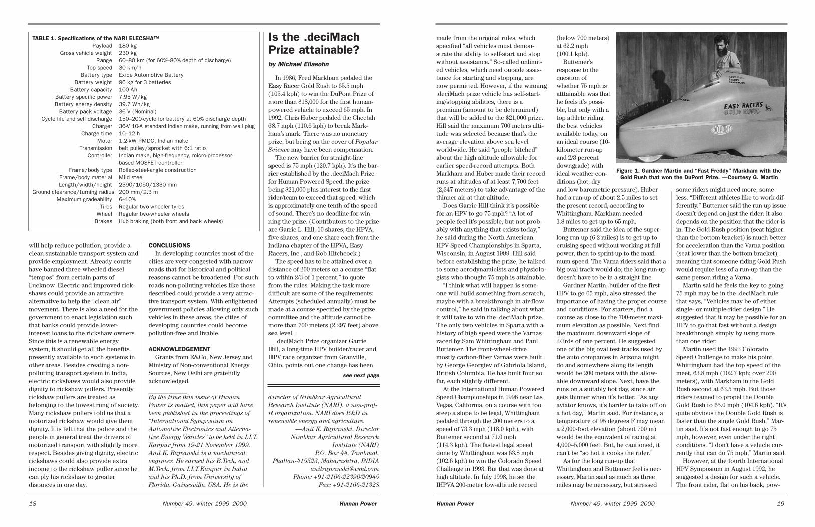
The new design of pedal rickshawhas a five-speed gear, a reduction inthe length of the long chain drives usedin existing rickshaws, back-wheel brak-ing, better suspension and a loweraerodynamic drag than the existing
CYCLE RICKSHAWS AS A SUSTAINABLE TRANSPORT SYSTEM FOR DEVELOPING COUNTRIESby Anil K. Rajvanshi
Figure 1. NARI improved pedal-cycle rickshaw (IPCR)
14 Number 49, winter 1999–2000 Human Power Human Power Number 49, winter 1999–2000 15
charging stations will have to be sortedout.
The electricity to power these batter-ies could come from any renewablepower plants like biomass, solar ther-mal, solar photovoltaic, wind, etc. Inthese cases these rickshaws could trulybe called a renewable-energy transportsystem. To convert all existing one-mil-lion rickshaws in India into electricrickshaws would require only one 600-MW power plant to run them. [If bat-tery-charging is carried out off-peak,including during the night, no addition-al generating plant would be required.—Ed.] It is also instructive to look atthe energy efficiency of electric rick-shaw vis-à-vis petrol-engine-poweredautorickshaws. From power-plant totraction-energy point of view ELEC-SHA consumes 110 Wh/passenger-kmas compared to 175 Wh/passenger-kmconsumed by petrol autorickshaws. Inthis calculation we used the followingassumptions.ELECSHA• The efficiency of electric power
plants including transmission anddistribution losses = 0.255;
• Charging/discharging efficiency ofbatteries = 0.64; and
• The Elecsha takes two passengersand travels 80 km per charge.
Petrol autorickshaw• Average mileage = 25 km/l of petrol • Calorific value of petrol 8.74 kWh/l
Thus if the ELECSHA uses batteriescharged from fossil-fuel powerstations, it would use 60% less petro-leum energy than a petrol autorick-shaw. Besides being environmentally-friendly ELECSHA is also very energy-efficient. We also feel that smallsystems like rickshaws are most suitedfor electric-vehicle development. Thisis because the present level of batterytechnology precludes large poweroutputs from lightweight batteries.Hence, the electric rickshaw can beeasily designed with existing motorand battery technology.Policy issues
There is need for a policy decisionby governments of developing coun-tries to permit only improved cyclerickshaws and electric rickshaws incongested areas of inner cities. This
the rickshaw puller can easily go30–40 km/day. The addition of a five-speed gear could therefore increase hisearnings substantially. MAPR
In this case our data have shownthat a rickshaw puller can easily pedal50 km/day and in some tests he hasincreased this distance to 70 km/day intwo shifts. Thus with the cost of MAPRat Rs 17,000 he can earn at leastRs 150/day (by charging Rs 3/km). Ifthe rickshaw owner charges Rs 40/dayas hiring charges (the puller will get atleast Rs 110/day as net income) thenthe owner will be able to repay therickshaw loan in five years. He will alsoat the same time earn a profit of aboutRs 4,600/year for ten years on eachrickshaw. This includes battery replace-ment cost every third year and 18%interest on the loan. ELECSHA
The ELECSHA owner can make a netprofit of Rs 25,400 every year for tenyears. This requires that the fare will beRs 3.50/km and that the rickshaw willtravel 70 km/day. Other assumptionsare:• Driver will be paid Rs 75/day; • ELECSHA will run for 300 days/year;• Battery replacement cost is Rs 15,000
and it will be replaced every otheryear;
• Interest is 15% per annum and loanhas to be paid back in five years; and
• The electricity cost is Rs 5/kWh.Presently the petrol autorickshaws
charge Rs 4.50/km and hence, even
with the reduced fare for ELECSHA,the owner can make a good profit. Thisis because of the low running cost ofELECSHA. Thus it seems that for bothrickshaw puller and owner it iseconomically viable to ply these rick-shaws.
OTHER ISSUESThe battery and its charging
One of the major issues facing thelarge-scale introduction of electricvehicles is the issue of batteries. Withthe present level of technology devel-opment the batteries used virtuallyhave to be lead-acid. Deep-dischargelead-acid batteries are presentlyimported into India and are very heavy.The issue of battery charging can betackled in two ways.
1. An onboard charger that can beplugged into any electrical outlet can befitted. This concept has been used inmost of the electric vehicles. This con-cept can be attractive for private own-ers of ELECSHA. However thedisadvantage of this method is that itincreases the cost of ELECSHA sincethe charger will be a part of it.
2. A network of battery-charging sta-tions could be developed. In this con-cept it is envisaged that the battery-charging station would take out the dis-charged batteries from ELECSHA andput in a set of charged ones.
The advantages of this concept arethat one does not need to worry aboutcharging and the battery could be oflower capacity and hence lighter
weight, which in turnwill improve theperformance of thevehicle. Also, regularautomotive batteriescould be used whichcan be discharged toonly 50% depth. Atthe same time noextra cost of acharger is incurred.This concept will bevery useful for rick-shaws being used astaxis. Nevertheless,the issues of old vs.new batteries and theeconomic viability of
rickshaws, as shown in figure 1, theimproved NARI rickshaw. Tests done atour institute have also shown that itenables a rickshaw puller to take twopassengers on a 6–10% slope quite easi-ly and without getting down from hisseat. This rickshaw is made of mild-steel angles, is light in weight and issturdy. The weight of the rickshaw is90 kg; its life estimated to be7–10 years.
Our data from urban towns of Indiahave shown also that many rickshawpullers are migrant laborers fromvillages whose sole possessions aretheir rickshaws. Hence at night theyoften sleep on the cramped seat of therickshaw for fear of its being stolen.Our new design allows the seats to bearranged in such a way that a long bedresults which allows a rickshaw pullerto sleep properly without the fear ofhis rickshaw being stolen at night.
The cost of this rickshaw is estimatedto be Rs 7000 in mass production andcompares very well with Rs 4000–5000which is the cost of existing regularrickshaws. [In October 1999, $1.00 = Rupees(Rs) 43.44; 1 Euro = Rs 46.84. —Ed.] Motor-assisted pedal rickshaw (MAPR)
Our data (from discussions with rick-shaw pullers) also revealed that with asmall battery-driven motor [permanent-magnet DC (PMDC) type] attached tothe improved rickshaw (with a five-speed gear) it may be possible for therickshaw puller togo uphill with ease.Similarly he canalso carry loads atspeeds of10–15 km/h.Consequently cal-culations showedthat a 0.375 kWPMDC motor witha 24-V, 40-A-h lead-acid battery couldeasily take two pas-sengers on a 10%slope at a speed of10 km/h withoutthe rickshaw pullergetting down from
his seat. This would be a majorimprovement for him. A simple strategyhas been employed in this rickshaw. Amanual contact switch allows the rick-shaw puller to switch the motor on oroff depending upon his convenienceand load. Thus the gearing is arrangedsuch that pedal and motor work in tan-dem to ease the load on the rickshawpuller. A current-overload switch cutsoff the circuit when motor draws morethan 20 amps. However the rickshawpuller has to pedal continuously: thus itis a motor-assisted pedal rickshaw(MAPR). The weight of this rickshaw(including batteries) is 129 kg (figure 2).
The cost of this rickshaw is envisagedto be Rs 17,000 in mass production. Theprice includes rickshaw, PMDC motorand battery. Patents have been appliedfor for both the IPCR and the MAPR. ELECSHA
In major cities of India there arepetrol- and diesel-powered three-wheel-ers called autorickshaws. They aresome of the most polluting vehicles onIndian roads. They use two-strokeengines, inherently more polluting thanthe regular four-stroke engines. In addi-tion, data we have collected show thatin the traffic conditions prevalent inmost inner-city areas these autorick-shaws run at only 15–20 km/h. Theytherefore produce even more pollutionbecause they are designed to run effi-ciently at 40–45 km/h. The pollution isfurther compounded because they arecontinually starting and stopping. Ourdata also show that on an average
these autorickshaws travel about50–60 km per day. Based upon thesedata it was felt that an electric rick-shaw designed to run 60–80 km/chargeand with speeds of 25–30 km/h wouldbe an excellent substitute for theseautorickshaws. In a fair-weather coun-try like India, a silent and nonpollutingelectric rickshaw with the above attrib-utes could be a boon.
Consequently an electric cycle rick-shaw has been designed and built. Ithas been patented and registered asELECSHA™ (figure 3). At the time ofwriting it has logged more than3500 km in test runs. It runs on a 36-V100-A-h lead-acid battery that powers a1.3-kW PMDC motor. An electroniccard “soft starts” ELECSHA and pro-vides dynamic braking. It is estimatedto cost about Rs 70,000 in mass produc-tion, which would compare very favor-ably with the cost of petrol- and diesel-powered three-wheelers which arepriced in some cities between Rs75,000–1,00,000. Table 1 shows thespecifications of the ELECSHA. Effortsare being made to reduce its weightand to make it easy to drive. This couldalso help it to become a low-cost per-sonal vehicle for middle-class families.
ECONOMIC ISSUESWe plan to introduce these rick-
shaws in Lucknow and Pune, citieshaving the maximum number of cyclerickshaws and autorickshaws respec-tively. The comparison of electric rick-shaws and autorickshaws can takeplace only when ELECSHA is used inactual conditions. However, a simpleeconomic analysis based upon existingdata has been accomplished, as fol-lows. IPCR
Discussions with rickshaw pullers invarious cities reveal that they propeltheir rickshaws to a maximum of25–30 km/day. During the hot season(which is the majority of the year)their range is reduced to 15–20km/day. On an average they charge Rs3–5/km. Hence they can make betweenRs 75–125/day. After giving Rs 15/dayas rickshaw hiring charges they canearn about Rs 60–110/day. Data on ourrickshaw have shown that with gears
Figure 2. Motor-assisted pedal rickshaw (MAPR) Figure 3. Electric cycle rickshaw (ELECSHA™)
16 Number 49, winter 1999–2000 Human Power Human Power Number 49, winter 1999–2000 17
In 1986, Fred Markham pedaled theEasy Racer Gold Rush to 65.5 mph(105.4 kph) to win the DuPont Prize ofmore than $18,000 for the first human-powered vehicle to exceed 65 mph. In1992, Chris Huber pedaled the Cheetah68.7 mph (110.6 kph) to break Mark-ham’s mark. There was no monetaryprize, but being on the cover of Popular
Science may have been compensation. The new barrier for straight-line
speed is 75 mph (120.7 kph). It’s the bar-rier established by the .deciMach Prizefor Human Powered Speed, the prizebeing $21,000 plus interest to the firstrider/team to exceed that speed, whichis approximately one-tenth of the speedof sound. There’s no deadline for win-ning the prize. (Contributors to the prizeare Garrie L. Hill, 10 shares; the HPVA,five shares, and one share each from theIndiana chapter of the HPVA, EasyRacers, Inc., and Rob Hitchcock.)
The speed has to be attained over adistance of 200 meters on a course “flatto within 2/3 of 1 percent,” to quotefrom the rules. Making the task moredifficult are some of the requirements:Attempts (scheduled annually) must bemade at a course specified by the prizecommittee and the altitude cannot bemore than 700 meters (2,297 feet) abovesea level.
.deciMach Prize organizer GarrieHill, a long-time HPV builder/racer andHPV race organizer from Granville,Ohio, points out one change has been
18 Number 49, winter 1999–2000 Human Power
director of Nimbkar Agricultural
Research Institute (NARI), a non-prof-
it organization. NARI does R&D in
renewable energy and agriculture.
—Anil K. Rajvanshi, Director
Nimbkar Agricultural Research
Institute (NARI)
P.O. Box 44, Tambmal,
Phaltan-415523, Maharashtra, INDIA
Phone: +91-2166-22396/20945
Fax: +91-2166-21328
will help reduce pollution, provide aclean sustainable transport system andprovide employment. Already courtshave banned three-wheeled diesel“tempos” from certain parts ofLucknow. Electric and improved rick-shaws could provide an attractivealternative to help the “clean air”movement. There is also a need for thegovernment to enact legislation suchthat banks could provide lower-interest loans to the rickshaw owners.Since this is a renewable energysystem, it should get all the benefitspresently available to such systems inother areas. Besides creating a non-polluting transport system in India,electric rickshaws would also providedignity to rickshaw pullers. Presentlyrickshaw pullers are treated asbelonging to the lowest rung of society.Many rickshaw pullers told us that amotorized rickshaw would give themdignity. It is felt that the police and thepeople in general treat the drivers ofmotorized transport with slightly morerespect. Besides giving dignity, electricrickshaws could also provide extraincome to the rickshaw puller since hecan ply his rickshaw to greaterdistances in one day.
CONCLUSIONSIn developing countries most of the
cities are very congested with narrowroads that for historical and politicalreasons cannot be broadened. For suchroads non-polluting vehicles like thosedescribed could provide a very attrac-tive transport system. With enlightenedgovernment policies allowing only suchvehicles in these areas, the cities ofdeveloping countries could becomepollution-free and livable.
ACKNOWLEDGEMENTGrants from E&Co, New Jersey and
Ministry of Non-conventional EnergySources, New Delhi are gratefullyacknowledged.
By the time this issue of Human
Power is mailed, this paper will have
been published in the proceedings of
“International Symposium on
Automotive Electronics and Alterna-
tive Energy Vehicles” to be held in I.I.T.
Kanpur from 19-21 November 1999.
Anil K. Rajvanshi is a mechanical
engineer. He earned his B.Tech. and
M.Tech. from I.I.T.Kanpur in India
and his Ph.D. from University of
Florida, Gainesville, USA. He is the
TABLE 1. Specifications of the NARI ELECSHA™Payload 180 kg
Gross vehicle weight 230 kgRange 60–80 km (for 60%–80% depth of discharge)
Top speed 30 km/hBattery type Exide Automotive Battery
Battery weight 96 kg for 3 batteriesBattery capacity 100 Ah
Battery specific power 7.95 W/kgBattery energy density 39.7 Wh/kg
Battery pack voltage 36 V (Nominal)Cycle life and self discharge 150–200-cycle for battery at 60% discharge depth
Charger 36-V 10-A standard Indian make, running from wall plug Charge time 10–12 h
Motor 1.2-kW PMDC, Indian makeTransmission belt pulley/sprocket with 6:1 ratio
Controller Indian make, high-frequency, micro-processor-based MOSFET controller
Frame/body type Rolled-steel-angle constructionFrame/body material Mild steelLength/width/height 2390/1050/1330 mm
Ground clearance/turning radius 200 mm/2.3 mMaximum gradeability 6–10%
Tires Regular two-wheeler tyresWheel Regular two-wheeler wheels
Brakes Hub braking (both front and back wheels)
made from the original rules, whichspecified “all vehicles must demon-strate the ability to self-start and stopwithout assistance.” So-called unlimit-ed vehicles, which need outside assis-tance for starting and stopping, arenow permitted. However, if the winning.deciMach prize vehicle has self-start-ing/stopping abilities, there is apremium (amount to be determined)that will be added to the $21,000 prize.Hill said the maximum 700 meters alti-tude was selected because that’s theaverage elevation above sea levelworldwide. He said “people bitched”about the high altitude allowable forearlier speed-record attempts. BothMarkham and Huber made their recordruns at altitudes of at least 7,700 feet(2,347 meters) to take advantage of thethinner air at that altitude.
Does Garrie Hill think it’s possiblefor an HPV to go 75 mph? “A lot ofpeople feel it’s possible, but not prob-ably with anything that exists today,”he said during the North AmericanHPV Speed Championships in Sparta,Wisconsin, in August 1999. Hill saidbefore establishing the prize, he talkedto some aerodynamicists and physiolo-gists who thought 75 mph is attainable.
“I think what will happen is some-one will build something from scratch,maybe with a breakthrough in air-flowcontrol,” he said in talking about whatit will take to win the .deciMach prize.The only two vehicles in Sparta with ahistory of high speed were the Varnasraced by Sam Whittingham and PaulButtemer. The front-wheel-drivemostly carbon-fiber Varnas were builtby George Georgiev of Gabriola Island,British Columbia. He has built four sofar, each slightly different.
At the International Human PoweredSpeed Championships in 1996 near LasVegas, California, on a course with toosteep a slope to be legal, Whittinghampedaled through the 200 meters to aspeed of 73.3 mph (118.0 kph), withButtemer second at 71.0 mph(114.3 kph). The fastest legal speeddone by Whittingham was 63.8 mph(102.6 kph) to win the Colorado SpeedChallenge in 1993. But that was done athigh altitude. In July 1998, he set theIHPVA 200-meter low-altitude record
(below 700 meters)at 62.2 mph(100.1 kph).
Buttemer’sresponse to thequestion ofwhether 75 mph isatttainable was thathe feels it’s possi-ble, but only with atop athlete ridingthe best vehiclesavailable today, onan ideal course (10-kilometer run-upand 2/3 percentdowngrade) withideal weather con-ditions (hot, dryand low barometric pressure). Huberhad a run-up of about 2.5 miles to setthe present record, according toWhittingham. Markham needed1.8 miles to get up to 65 mph.
Buttemer said the idea of the super-long run-up (6.2 miles) is to get up tocruising speed without working at fullpower, then to sprint up to the maxi-mum speed. The Varna riders said that abig oval track would do; the long run-updoesn’t have to be in a straight line.
Gardner Martin, builder of the firstHPV to go 65 mph, also stressed theimportance of having the proper courseand conditions. For starters, find acourse as close to the 700-meter maxi-mum elevation as possible. Next findthe maximum downward slope of2/3rds of one percent. He suggestedone of the big oval test tracks used bythe auto companies in Arizona mightdo and somewhere along its lengthwould be 200 meters with the allow-able downward slope. Next, have theruns on a suitably hot day, since airgets thinner when it’s hotter. “As anyaviator knows, it’s harder to take off ona hot day,” Martin said. For instance, atemperature of 95 degrees F may meana 2,000-foot elevation (about 700 m)would be the equivalent of racing at4,000–5,000 feet. But, he cautioned, itcan’t be “so hot it cooks the rider.”
As for the long run-up thatWhittingham and Buttemer feel is nec-essary, Martin said as much as threemiles may be necessary, but stressed
some riders might need more, someless. “Different athletes like to work dif-ferently.” Buttemer said the run-up issuedoesn’t depend on just the rider: it alsodepends on the position that the rider isin. The Gold Rush position (seat higherthan the bottom bracket) is much betterfor acceleration than the Varna position(seat lower than the bottom bracket),meaning that someone riding Gold Rushwould require less of a run-up than thesame person riding a Varna.
Martin said he feels the key to going75 mph may be in the .deciMach rulethat says, “Vehicles may be of eithersingle- or multiple-rider design.” Hesuggested that it may be possible for anHPV to go that fast without a designbreakthrough simply by using morethan one rider.
Martin used the 1993 ColoradoSpeed Challenge to make his point.Whittingham had the top speed of themeet, 63.8 mph (102.7 kph; over 200meters), with Markham in the GoldRush second at 63.5 mph. But thoseriders teamed to propel the DoubleGold Rush to 65.0 mph (104.6 kph). “It’squite obvious the Double Gold Rush isfaster than the single Gold Rush,” Mar-tin said. It’s not fast enough to go 75mph, however, even under the rightconditions. “I don’t have a vehicle cur-rently that can do 75 mph,” Martin said.
However, at the fourth InternationalHPV Symposium in August 1992, hesuggested a design for such a vehicle.The front rider, flat on his back, pow-
Human Power Number 49, winter 1999–2000 19
Is the .deciMachPrize attainable?by Michael Eliasohn
Figure 1. Gardner Martin and “Fast Freddy” Markham with theGold Rush that won the DuPont Prize. —Courtesy G. Martin
see next page
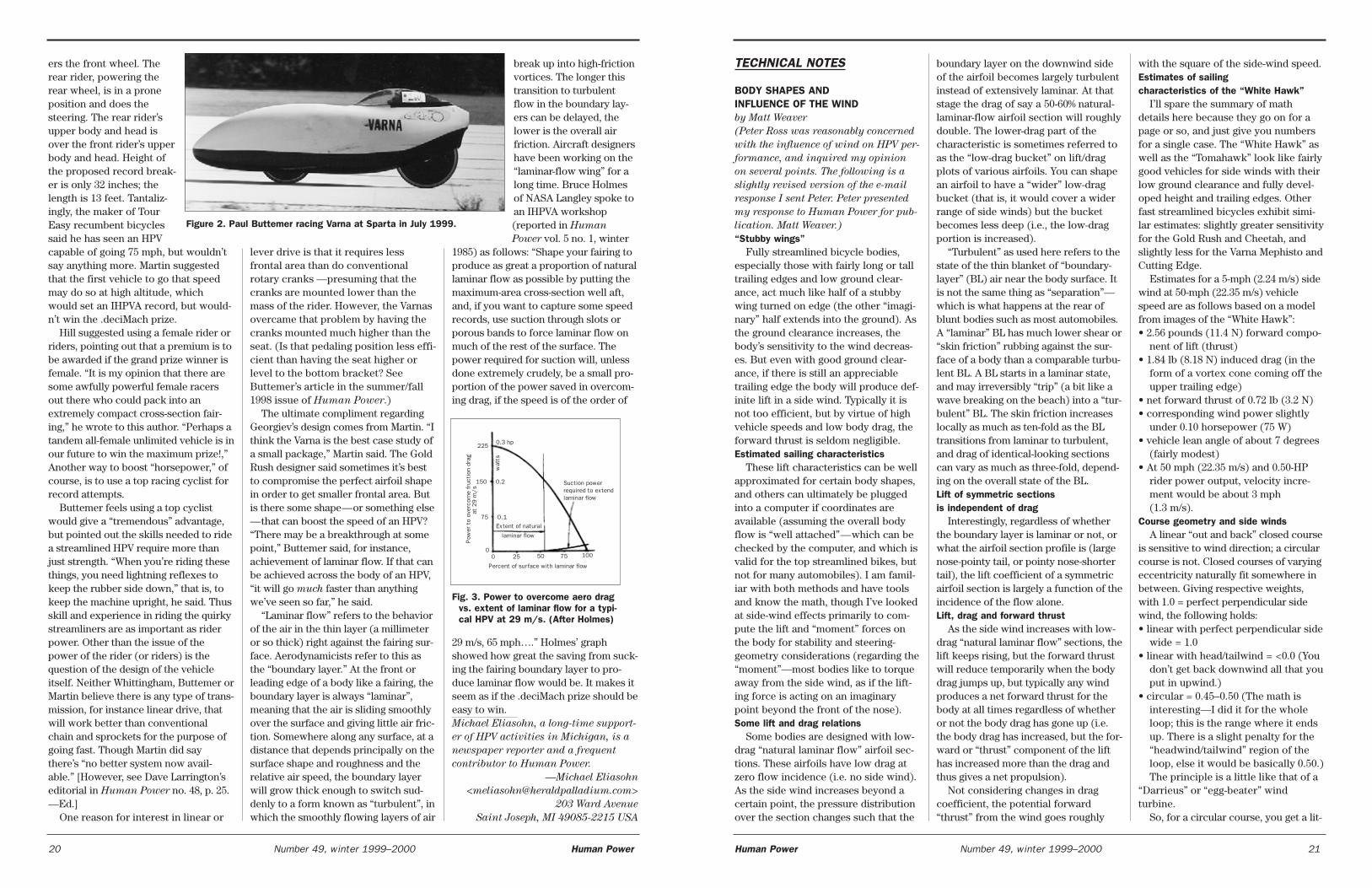
ers the front wheel. Therear rider, powering therear wheel, is in a proneposition and does thesteering. The rear rider’supper body and head isover the front rider’s upperbody and head. Height ofthe proposed record break-er is only 32 inches; thelength is 13 feet. Tantaliz-ingly, the maker of TourEasy recumbent bicyclessaid he has seen an HPVcapable of going 75 mph, but wouldn’tsay anything more. Martin suggestedthat the first vehicle to go that speedmay do so at high altitude, whichwould set an IHPVA record, but would-n’t win the .deciMach prize.
Hill suggested using a female rider orriders, pointing out that a premium is tobe awarded if the grand prize winner isfemale. “It is my opinion that there aresome awfully powerful female racersout there who could pack into anextremely compact cross-section fair-ing,” he wrote to this author. “Perhaps atandem all-female unlimited vehicle is inour future to win the maximum prize!,”Another way to boost “horsepower,” ofcourse, is to use a top racing cyclist forrecord attempts.
Buttemer feels using a top cyclistwould give a “tremendous” advantage,but pointed out the skills needed to ridea streamlined HPV require more thanjust strength. “When you’re riding thesethings, you need lightning reflexes tokeep the rubber side down,” that is, tokeep the machine upright, he said. Thusskill and experience in riding the quirkystreamliners are as important as riderpower. Other than the issue of thepower of the rider (or riders) is thequestion of the design of the vehicleitself. Neither Whittingham, Buttemer orMartin believe there is any type of trans-mission, for instance linear drive, thatwill work better than conventionalchain and sprockets for the purpose ofgoing fast. Though Martin did saythere’s “no better system now avail-able.” [However, see Dave Larrington’seditorial in Human Power no. 48, p. 25.—Ed.]
One reason for interest in linear or
lever drive is that it requires lessfrontal area than do conventionalrotary cranks —presuming that thecranks are mounted lower than themass of the rider. However, the Varnasovercame that problem by having thecranks mounted much higher than theseat. (Is that pedaling position less effi-cient than having the seat higher orlevel to the bottom bracket? SeeButtemer’s article in the summer/fall1998 issue of Human Power.)
The ultimate compliment regardingGeorgiev’s design comes from Martin. “Ithink the Varna is the best case study ofa small package,” Martin said. The GoldRush designer said sometimes it’s bestto compromise the perfect airfoil shapein order to get smaller frontal area. Butis there some shape—or something else—that can boost the speed of an HPV?“There may be a breakthrough at somepoint,” Buttemer said, for instance,achievement of laminar flow. If that canbe achieved across the body of an HPV,“it will go much faster than anythingwe’ve seen so far,” he said.
“Laminar flow” refers to the behaviorof the air in the thin layer (a millimeteror so thick) right against the fairing sur-face. Aerodynamicists refer to this asthe “boundary layer.” At the front orleading edge of a body like a fairing, theboundary layer is always “laminar”,meaning that the air is sliding smoothlyover the surface and giving little air fric-tion. Somewhere along any surface, at adistance that depends principally on thesurface shape and roughness and therelative air speed, the boundary layerwill grow thick enough to switch sud-denly to a form known as “turbulent”, inwhich the smoothly flowing layers of air
break up into high-frictionvortices. The longer thistransition to turbulentflow in the boundary lay-ers can be delayed, thelower is the overall airfriction. Aircraft designershave been working on the“laminar-flow wing” for along time. Bruce Holmesof NASA Langley spoke toan IHPVA workshop(reported in Human
Power vol. 5 no. 1, winter1985) as follows: “Shape your fairing toproduce as great a proportion of naturallaminar flow as possible by putting themaximum-area cross-section well aft,and, if you want to capture some speedrecords, use suction through slots orporous bands to force laminar flow onmuch of the rest of the surface. Thepower required for suction will, unlessdone extremely crudely, be a small pro-portion of the power saved in overcom-ing drag, if the speed is of the order of
29 m/s, 65 mph….” Holmes’ graphshowed how great the saving from suck-ing the fairing boundary layer to pro-duce laminar flow would be. It makes itseem as if the .deciMach prize should beeasy to win. Michael Eliasohn, a long-time support-
er of HPV activities in Michigan, is a
newspaper reporter and a frequent
contributor to Human Power.
—Michael Eliasohn
203 Ward Avenue
Saint Joseph, MI 49085-2215 USA
20 Number 49, winter 1999–2000 Human Power
boundary layer on the downwind sideof the airfoil becomes largely turbulentinstead of extensively laminar. At thatstage the drag of say a 50-60% natural-laminar-flow airfoil section will roughlydouble. The lower-drag part of thecharacteristic is sometimes referred toas the “low-drag bucket” on lift/dragplots of various airfoils. You can shapean airfoil to have a “wider” low-dragbucket (that is, it would cover a widerrange of side winds) but the bucketbecomes less deep (i.e., the low-dragportion is increased).
“Turbulent” as used here refers to thestate of the thin blanket of “boundary-layer” (BL) air near the body surface. Itis not the same thing as “separation”—which is what happens at the rear ofblunt bodies such as most automobiles.A “laminar” BL has much lower shear or“skin friction” rubbing against the sur-face of a body than a comparable turbu-lent BL. A BL starts in a laminar state,and may irreversibly “trip” (a bit like awave breaking on the beach) into a “tur-bulent” BL. The skin friction increaseslocally as much as ten-fold as the BLtransitions from laminar to turbulent,and drag of identical-looking sectionscan vary as much as three-fold, depend-ing on the overall state of the BL. Lift of symmetric sections is independent of drag
Interestingly, regardless of whetherthe boundary layer is laminar or not, orwhat the airfoil section profile is (largenose-pointy tail, or pointy nose-shortertail), the lift coefficient of a symmetricairfoil section is largely a function of theincidence of the flow alone. Lift, drag and forward thrust
As the side wind increases with low-drag “natural laminar flow” sections, thelift keeps rising, but the forward thrustwill reduce temporarily when the bodydrag jumps up, but typically any windproduces a net forward thrust for thebody at all times regardless of whetheror not the body drag has gone up (i.e.the body drag has increased, but the for-ward or “thrust” component of the lifthas increased more than the drag andthus gives a net propulsion).
Not considering changes in dragcoefficient, the potential forward“thrust” from the wind goes roughly
TECHNICAL NOTES
BODY SHAPES AND INFLUENCE OF THE WIND by Matt Weaver
(Peter Ross was reasonably concerned
with the influence of wind on HPV per-
formance, and inquired my opinion
on several points. The following is a
slightly revised version of the e-mail
response I sent Peter. Peter presented
my response to Human Power for pub-
lication. Matt Weaver.)
“Stubby wings”Fully streamlined bicycle bodies,
especially those with fairly long or talltrailing edges and low ground clear-ance, act much like half of a stubbywing turned on edge (the other “imagi-nary” half extends into the ground). Asthe ground clearance increases, thebody’s sensitivity to the wind decreas-es. But even with good ground clear-ance, if there is still an appreciabletrailing edge the body will produce def-inite lift in a side wind. Typically it isnot too efficient, but by virtue of highvehicle speeds and low body drag, theforward thrust is seldom negligible. Estimated sailing characteristics
These lift characteristics can be wellapproximated for certain body shapes,and others can ultimately be pluggedinto a computer if coordinates areavailable (assuming the overall bodyflow is “well attached”—which can bechecked by the computer, and which isvalid for the top streamlined bikes, butnot for many automobiles). I am famil-iar with both methods and have toolsand know the math, though I’ve lookedat side-wind effects primarily to com-pute the lift and “moment” forces onthe body for stability and steering-geometry considerations (regarding the“moment”—most bodies like to torqueaway from the side wind, as if the lift-ing force is acting on an imaginarypoint beyond the front of the nose). Some lift and drag relations
Some bodies are designed with low-drag “natural laminar flow” airfoil sec-tions. These airfoils have low drag atzero flow incidence (i.e. no side wind).As the side wind increases beyond acertain point, the pressure distributionover the section changes such that the
with the square of the side-wind speed. Estimates of sailing characteristics of the “White Hawk”
I’ll spare the summary of mathdetails here because they go on for apage or so, and just give you numbersfor a single case. The “White Hawk” aswell as the “Tomahawk” look like fairlygood vehicles for side winds with theirlow ground clearance and fully devel-oped height and trailing edges. Otherfast streamlined bicycles exhibit simi-lar estimates: slightly greater sensitivityfor the Gold Rush and Cheetah, andslightly less for the Varna Mephisto andCutting Edge.
Estimates for a 5-mph (2.24 m/s) sidewind at 50-mph (22.35 m/s) vehiclespeed are as follows based on a modelfrom images of the “White Hawk”: • 2.56 pounds (11.4 N) forward compo-
nent of lift (thrust) • 1.84 lb (8.18 N) induced drag (in the
form of a vortex cone coming off theupper trailing edge)
• net forward thrust of 0.72 lb (3.2 N) • corresponding wind power slightly
under 0.10 horsepower (75 W) • vehicle lean angle of about 7 degrees
(fairly modest) • At 50 mph (22.35 m/s) and 0.50-HP
rider power output, velocity incre-ment would be about 3 mph(1.3 m/s).
Course geometry and side windsA linear “out and back” closed course
is sensitive to wind direction; a circularcourse is not. Closed courses of varyingeccentricity naturally fit somewhere inbetween. Giving respective weights,with 1.0 = perfect perpendicular sidewind, the following holds: • linear with perfect perpendicular side
wide = 1.0 • linear with head/tailwind = <0.0 (You
don’t get back downwind all that youput in upwind.)
• circular = 0.45–0.50 (The math isinteresting—I did it for the wholeloop; this is the range where it endsup. There is a slight penalty for the“headwind/tailwind” region of theloop, else it would be basically 0.50.)The principle is a little like that of a
“Darrieus” or “egg-beater” windturbine.
So, for a circular course, you get a lit-
Human Power Number 49, winter 1999–2000 21
Figure 2. Paul Buttemer racing Varna at Sparta in July 1999.
Percent of surface with laminar flow
Pow
er t
o ov
erco
me
fruc
tion
dra
gat
29 m
/s
225
150
75
0.3 hp
0.2
0.1
00 25 50 75 100
Suction powerrequired to extend laminar flow
Extent of natural
laminar flow
wat
ts
Fig. 3. Power to overcome aero dragvs. extent of laminar flow for a typi-cal HPV at 29 m/s. (After Holmes)
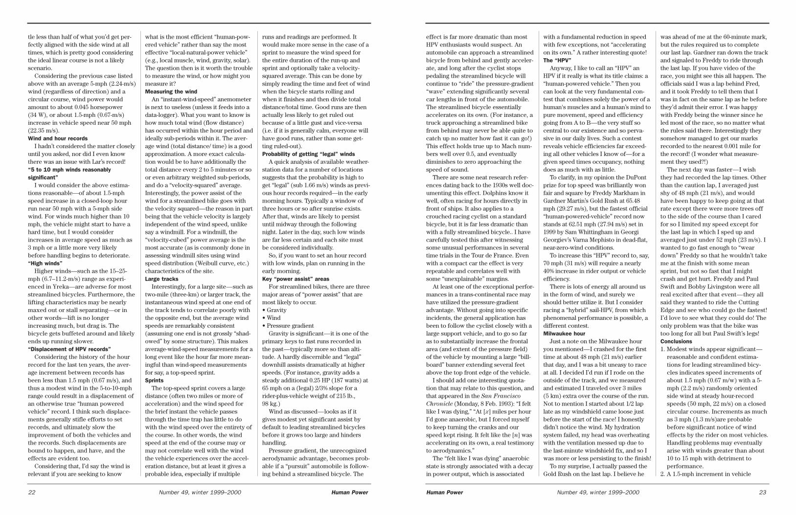
effect is far more dramatic than mostHPV enthusiasts would suspect. Anautomobile can approach a streamlinedbicycle from behind and gently acceler-ate, and long after the cyclist stopspedaling the streamlined bicycle willcontinue to “ride” the pressure-gradient“wave” extending significantly severalcar lengths in front of the automobile.The streamlined bicycle essentiallyaccelerates on its own. (For instance, atruck approaching a streamlined bikefrom behind may never be able quite tocatch up no matter how fast it can go!)This effect holds true up to Mach num-bers well over 0.5, and eventuallydiminishes to zero approaching thespeed of sound.
There are some neat research refer-ences dating back to the 1930s well doc-umenting this effect. Dolphins know itwell, often racing for hours directly infront of ships. It also applies to acrouched racing cyclist on a standardbicycle, but it is far less dramatic thanwith a fully streamlined bicycle.. I havecarefully tested this after witnessingsome unusual performances in severaltime trials in the Tour de France. Evenwith a compact car the effect is veryrepeatable and correlates well withsome “unexplainable” margins.
At least one of the exceptional perfor-mances in a trans-continental race mayhave utilized the pressure-gradientadvantage. Without going into specificincidents, the general application hasbeen to follow the cyclist closely with alarge support vehicle, and to go so faras to substantially increase the frontalarea (and extent of the pressure field)of the vehicle by mounting a large “bill-board” banner extending several feetabove the top front edge of the vehicle.
I should add one interesting quota-tion that may relate to this question, andthat appeared in the San Francisco
Chronicle (Monday, 8 Feb. 1993): “I feltlike I was dying,” “At [x] miles per hourI’d gone anaerobic, but I forced myselfto keep turning the cranks and ourspeed kept rising. It felt like the [n] wasaccelerating on its own, a real testimonyto aerodynamics.”
The “felt like I was dying” anaerobicstate is strongly associated with a decayin power output, which is associated
with a fundamental reduction in speedwith few exceptions, not “acceleratingon its own.” A rather interesting quote!The “HPV”
Anyway, I like to call an “HPV” anHPV if it really is what its title claims: a“human-powered vehicle.” Then youcan look at the very fundamental con-test that combines solely the power of ahuman's muscles and a human’s mind topure movement, speed and efficiencygoing from A to B—the very stuff socentral to our existence and so perva-sive in our daily lives. Such a contestreveals vehicle efficiencies far exceed-ing all other vehicles I know of—for agiven speed times occupancy, nothingdoes as much with as little.
To clarify, in my opinion the DuPontprize for top speed was brilliantly wonfair and square by Freddy Markham inGardner Martin’s Gold Rush at 65.48mph (29.27 m/s), but the fastest official“human-powered-vehicle” record nowstands at 62.51 mph (27.94 m/s) set in1999 by Sam Whittingham in GeorgiGeorgiev’s Varna Mephisto in dead-flat,near-zero-wind conditions.
To increase this “HPV” record to, say,70 mph (31 m/s) will require a nearly40% increase in rider output or vehicleefficiency.
There is lots of energy all around usin the form of wind, and surely weshould better utilize it. But I considerracing a “hybrid” sail-HPV, from whichphenomenal performance is possible, adifferent contest. Milwaukee hour
Just a note on the Milwaukee houryou mentioned—I crashed for the firsttime at about 48 mph (21 m/s) earlierthat day, and I was a bit uneasy to raceat all. I decided I’d run if I rode on theoutside of the track, and we measuredand estimated I traveled over 3 miles(5 km) extra over the course of the run.Not to mention I started about 1/2 laplate as my windshield came loose justbefore the start of the race! I honestlydidn’t notice the wind. My hydrationsystem failed, my head was overheatingwith the ventilation messed up due tothe last-minute windshield fix, and so Iwas more or less persisting to the finish!
To my surprise, I actually passed theGold Rush on the last lap. I believe he
was ahead of me at the 60-minute mark,but the rules required us to completeour last lap. Gardner ran down the trackand signaled to Freddy to ride throughthe last lap. If you have video of therace, you might see this all happen. Theofficials said I was a lap behind Fred,and it took Freddy to tell them that Iwas in fact on the same lap as he beforethey’d admit their error. I was happywith Freddy being the winner since heled most of the race, so no matter whatthe rules said there. Interestingly theysomehow managed to get our marksrecorded to the nearest 0.001 mile forthe record! (I wonder what measure-ment they used?!)
The next day was faster—I wishthey had recorded the lap times. Otherthan the caution lap, I averaged justshy of 48 mph (21 m/s), and wouldhave been happy to keep going at thatrate except there were more trees offto the side of the course than I caredfor so I limited my speed except forthe last lap in which I sped up andaveraged just under 52 mph (23 m/s). Iwanted to go fast enough to “weardown” Freddy so that he wouldn’t takeme at the finish with some meansprint, but not so fast that I mightcrash and get hurt. Freddy and PaulSwift and Bobby Livingston were allreal excited after that event—they allsaid they wanted to ride the CuttingEdge and see who could go the fastest!I’d love to see what they could do! Theonly problem was that the bike wastoo long for all but Paul Swift’s legs! Conclusions1. Modest winds appear significant—
reasonable and confident estima-tions for leading streamlined bicy-cles indicates speed increments ofabout 1.5 mph (0.67 m/w) with a 5-mph (2.2 m/s) randomly orientedside wind at steady hour-recordspeeds (50 mph, 22 m/s) on a closedcircular course. Increments as muchas 3 mph (1.3 m/s)are probablebefore significant notice of windeffects by the rider on most vehicles.Handling problems may eventuallyarise with winds greater than about10 to 15 mph with detriment toperformance.
2. A 1.5-mph increment in vehicle
Human Power Number 49, winter 1999–2000 23
tle less than half of what you’d get per-fectly aligned with the side wind at alltimes, which is pretty good consideringthe ideal linear course is not a likelyscenario.
Considering the previous case listedabove with an average 5-mph (2.24-m/s)wind (regardless of direction) and acircular course, wind power wouldamount to about 0.045 horsepower(34 W), or about 1.5-mph (0.67-m/s)increase in vehicle speed near 50 mph(22.35 m/s). Wind and hour records
I hadn’t considered the matter closelyuntil you asked, nor did I even knowthere was an issue with Lar’s record! “5 to 10 mph winds reasonablysignificant”
I would consider the above estima-tions reasonable—of about 1.5-mphspeed increase in a closed-loop hourrun near 50 mph with a 5-mph sidewind. For winds much higher than 10mph, the vehicle might start to have ahard time, but I would considerincreases in average speed as much as3 mph or a little more very likelybefore handling begins to deteriorate. “High winds”
Higher winds—such as the 15–25-mph (6.7–11.2-m/s) range as experi-enced in Yreka—are adverse for moststreamlined bicycles. Furthermore, thelifting characteristics may be nearlymaxed out or stall separating—or inother words—lift is no longerincreasing much, but drag is. Thebicycle gets buffeted around and likelyends up running slower. “Displacement of HPV records”
Considering the history of the hourrecord for the last ten years, the aver-age increment between records hasbeen less than 1.5 mph (0.67 m/s), andthus a modest wind in the 5-to-10-mphrange could result in a displacement ofan otherwise true “human poweredvehicle” record. I think such displace-ments generally stifle efforts to setrecords, and ultimately slow theimprovement of both the vehicles andthe records. Such displacements arebound to happen, and have, and theeffects are evident too.
Considering that, I’d say the wind isrelevant if you are seeking to know
what is the most efficient “human-pow-ered vehicle” rather than say the mosteffective “local-natural-power vehicle”(e.g., local muscle, wind, gravity, solar).The question then is it worth the troubleto measure the wind, or how might youmeasure it?Measuring the wind
An “instant-wind-speed” anemometeris next to useless (unless it feeds into adata-logger). What you want to know ishow much total wind (flow distance)has occurred within the hour period andideally sub-periods within it. The aver-age wind (total distance/ time) is a goodapproximation. A more exact calcula-tion would be to have additionally thetotal distance every 2 to 5 minutes or soor even arbitrary weighted sub-periods,and do a “velocity-squared” average.Interestingly, the power assist of thewind for a streamlined bike goes withthe velocity squared—the reason in partbeing that the vehicle velocity is largelyindependent of the wind speed, unlikesay a windmill. For a windmill, the“velocity-cubed” power average is themost accurate (as is commonly done inassessing windmill sites using windspeed distribution (Weibull curve, etc.)characteristics of the site.Large tracks
Interestingly, for a large site—such astwo-mile (three-km) or larger track, theinstantaneous wind speed at one end ofthe track tends to correlate poorly withthe opposite end, but the average windspeeds are remarkably consistent(assuming one end is not grossly “shad-owed” by some structure). This makesaverage-wind-speed measurements for along event like the hour far more mean-ingful than wind-speed measurementsfor say, a top-speed sprint.Sprints
The top-speed sprint covers a largedistance (often two miles or more ofacceleration) and the wind speed forthe brief instant the vehicle passesthrough the time trap has little to dowith the wind speed over the entirety ofthe course. In other words, the windspeed at the end of the course may ormay not correlate well with the windthe vehicle experiences over the accel-eration distance, but at least it gives aprobable idea, especially if multiple
runs and readings are performed. Itwould make more sense in the case of asprint to measure the wind speed forthe entire duration of the run-up andsprint and optionally take a velocity-squared average. This can be done bysimply reading the time and feet of windwhen the bicycle starts rolling andwhen it finishes and then divide totaldistance/total time. Good runs are thenactually less likely to get ruled outbecause of a little gust and vice-versa(i.e. if it is generally calm, everyone willhave good runs, rather than some get-ting ruled-out). Probability of getting “legal” winds
A quick analysis of available weather-station data for a number of locationssuggests that the probability is high toget “legal” (sub 1.66 m/s) winds as previ-ous hour records required—in the earlymorning hours. Typically a window ofthree hours or so after sunrise exists.After that, winds are likely to persistuntil midway through the followingnight. Later in the day, such low windsare far less certain and each site mustbe considered individually.
So, if you want to set an hour recordwith low winds, plan on running in theearly morning.Key “power assist” areas
For streamlined bikes, there are threemajor areas of “power assist” that aremost likely to occur.• Gravity• Wind• Pressure gradient
Gravity is significant—it is one of theprimary keys to fast runs recorded inthe past—typically more so than alti-tude. A hardly discernible and “legal”downhill assists dramatically at higherspeeds. (For instance, gravity adds asteady additional 0.25 HP (187 watts) at65 mph on a (legal) 2/3% slope for arider-plus-vehicle weight of 215 lb.,98 kg.)
Wind as discussed—looks as if itgives modest yet significant assist bydefault to leading streamlined bicyclesbefore it grows too large and hindershandling.
Pressure gradient, the unrecognizedaerodynamic advantage, becomes prob-able if a “pursuit” automobile is follow-ing behind a streamlined bicycle. The
22 Number 49, winter 1999–2000 Human Power
24 Number 49, winter 1999–2000 Human Power
seems that I misinterpreted Too’s defi-nition of the non-recumbent position,termed “standard upright-cycleergometer position”.
The complete article explained thatwhile the seat-tube angle was the stan-dard 75° for an exercise ergometer, thesubject’s upper body was kept perpen-dicular to the ground. Requiring theupper body to stay perpendicular tothe ground is not “standard” whencycling at a 75° seat-tube angle.Subjects generally prefer to leanforward approximately 30° fromvertical. This 30° difference in the stan-dard torso position and the uprighttorso position could account for thereduced power produced in the uprightposition compared to the recumbentposition, making recumbent cycling nomore powerful that standard cycling.The tested upright cycling positionrequired the subjects to cycle with thehips in an extended position, reducingthe length and force capacity of the hipmusculature compared to the recum-bent position.
This upright cycling position wasalso tested in “Comparisons betweenupright and recumbent cycle ergom-etry with changes in crank-arm length”(Too, 1998).
Additionally, in Too (1996), subjectswere not tested in a random order. Thetesting also included a three-monthinterval between the upright andrecumbent test position. In addition, aslightly different definition of seat-to-pedal distance was used in each posi-tion. However, it does not seem thatthe order of testing, time betweentesting, and different seat-to-pedaldistance affected the results dramati-cally. The results in “The effect of hipposition/configuration on anaerobicpower capacity in cycling” (Too, 1991)showed similar positions being testedand the same conclusions were drawn.However, the discrepancies in the datacollection could cause erroneousresults and, at the very least, changethe magnitude of the differences whichwould change the levels of signifi-cance. This example illustrates howabstracts, and possibly review articles,may become too concise for clarity.
Clarification of some of the confu-
ed demonstrating following dis-tances in excess of 100 feet at alltimes except maybe momentarily atthe finish for marking purposes only.
11. Arbitrary wind should be allowedfor long-duration records (two hoursor more) from a practical standpoint,but should still be recorded andmaybe velocity-squared power aver-aged for purposes of meaningfulcomparison of achievements (notunlike the documentation of altitudeor course slope).
—Matt Weaver, Aptos, CA
LETTERS
COMMENTS ON ABSTRACTS OF TOO’S DATA
Dr. Too has made a significant con-tribution to recumbent design and itwas helpful of him to allow the IHPVAto reprint several of his researchabstracts along with the questions andanswers from the IHPVA list server inHuman Power (No. 46, pp. 14–20). Theabstracts combined with his commentsfill in some of the gaps left by myreview article (Reiser and Peterson,1998. “Lower-extremity power output inrecumbent cycling: a literature review.”Human Power, No. 45, pp. 6–13).
While review articles and abstractshelp to consolidate information, theyare an incomplete substitute for thework from which they are drawn.Many of the details of a study must beleft out when reducing a multi-pagedocument to a couple of sentences oreven a couple of paragraphs. This canlead to confusion and misinterpreta-tion by the reader. One such exampleof being too concise for clarity is theabstract for “Comparison of joint angleand power production during uprightand recumbent cycle ergometry” (Too,1996). After reading the abstract I wasleft with the impression that anaerobicpower output was greater in therecumbent cycling position (15° seat-tube angle relative to horizontal)compared to the standard cycling posi-tion with a 75° seat-tube angle. Thisresult was very surprising to me, so Itracked down the complete article. It
speed is larger than the averageincrement in the world hour recordover the last four or so records set inthe last ten years.
3. Circular courses—yield about 45% ofthe power assist a perfect side windwould give.
4. The probability is high to obtain“legal” (sub 1.66 m/s or 3.71 mph)winds in the early morning hours formost courses, but the probability ofhaving “legal” winds is not very highat other times of daylight.
5. Instantaneous wind measurementsmay correlate poorly at differentpoints on the course, but averagesare remarkably consistent over sev-eral miles or more in flat areasassuming no wind shadowing at thepoint of measurement.
6. Wind measurement is relatively sim-ple and meaningful if done as “totaldistance” of wind per hour. Moreprecise readings would involve a“velocity squared” average for landvehicles (not velocity cubed as forwindmills).
7. Weather data of Frankfurt/Main sug-gest that there may have been windin the 5–10 mph (2.2–4.5 m/s) rangeat the 8 PM European time7 Aug. 1999 of the latest hour recordattempt.
8. Check if the track has a weather sta-tion as most test tracks do, or othernearby station evidence of the condi-tions. If the track weather stationconfidently shows legal wind at thetime of the race, then that measure-ment should be respected and con-sidered official.
9. Previous records and other teamshave been held to certain require-ments that appear to have significanteffect on performance. Until therules are changed, it is a simple mat-ter to uphold this well-known andsimple-to-measure requirement if anofficial record is desired. Otherwise,to exempt generously the latestclaim simultaneously rejects the pre-vious official record holder’s titleand may also displace potentialfuture HPV record achievements.
10. The position of any “chase” or sup-port vehicle behind the streamlinedbicycle should be clearly document-
sion (in particular Too, 1996) maybenefit other interested parties, sincethe abstract in question has beenmisinterpreted elsewhere.
—Raoul F. Reiser II, M.A., C.S.C.S.
Dept. of Mechanical Engineering
Colorado State University
RELATIONS WITH THE UCI(Following is a letter from Peter Ross
to the IHPVA board in response to an
inquiry on who had made approaches
to the UCI. He and they have given me
permission to reproduce it here.
—Dave Wilson.)
Yes, it was I who wrote to the UCIduring the time that the Re-organizationCommittee was preparing proposals forthe new IHPVA. The reaction wasfriendly, and the UCI accepted that theyhad categories (now dormant) thatwould allow cycles not meeting the cur-rent UCI racing rules to compete.
The way matters were left was thatthe new president of the IHPVA, whenhe/she was finally appointed, shouldarrange an informal meeting with theUCI administration.
I still think that this would be a goodidea, so long as it was on a strictlyexploratory basis. I also think that weshould attempt to revive the dormantUCI rules, and get them to agree that weshould administer them on their behalf.This would allow national cycle clubs tosanction HPV races as part of regularbike contests without falling foul of theUCI, and avoid the risk of UCI licenceholders losing their licence if they tookpart in such an event.
One of the by-products of my briefcontact with the UCI was the recogni-tion that we, in the HPV movement,should draw up and agree on a defini-tion of an unstreamlined HPV forrecord-breaking purposes. At themoment the IHPVA recognises onlyultimate speed by any vehicle (withoutstored power), and of course thefastest bikes all have aerodynamic fair-ings. In my opinion the current Euro-pean rules for non-faired racing HPVshave become ridiculous, with anycompetitor wanting to do well havingto fit what is virtually the rear half of afull hard-shell fairing, which does nothave to perform any load-carrying
function whatsoever, and makes fixinga rear-wheel puncture a near impossi-bility.My suggested definition would be:
“Machines of all kinds that functionby the power of one human only, thatrequire no apparatus or device intendedto reduce air resistance and that do notexceed the dimensions of 2 metres inlength and 750 mm in width. “ It is nocoincidence that this is virtually theidentical wording of UCI Article 31 as itwas in 1933 when Francis Faure brokethe hour record in the Mochet Velocar.
We would now need to add that thereshould be no stored energy at the startof the attempt. For US readers 2 metresis 78.74 inches (6 ft 6.74 in) and 750 mmis 29.53 inches (2 ft 5.53 in).
—Peter Ross, UK
GREETINGS FROM ALASKAI greatly enjoyed the last two issues
of Human Power, especially the discus-sion of hill climbing. My experience onhills with recumbents vs. uprights hasbeen the same as Mr. Buttemer’s andmany others. Recumbents are slowerthan uprights on hills and the steeperthe hill the greater the differential. In anattempt to correct this I varied the seatheight on my recumbent (a medium-wheel-base 1040 mm, 41", made from anold Moulton 4-speed) by as much aseight inches (200 mm) above to oneinch below the bottom-bracket height. Itdidn’t seem to make much difference. Ifanything, the lower seat is slightly bet-ter but it is a mute point because anyone of my uprights loaded to the sameweight — even my fat-tire mountainbikes—- are much faster up the samehill. Over the years I have had all toomuch time to think about this problemwhile twiddling my recumbent up hills. Ihave come to the conclusion that muchof the poor performance of recumbentsis due to the following.
Because of their low center of gravity,recumbents are inherently more diffi-cult to balance than uprights. At moder-ate to high speeds the difference is notmuch but the lower the speed thegreater the differential, even on theflats. (Does this sound familiar?)However, not all of the difference inlow-speed handling (balance) is due to
the height of the center of gravity. Agood share of the difference is due tothe fact that while the upper bodies ofupright riders are unrestricted relativeto lateral movement, the seats of recum-bents greatly restrict this type of move-ment. Therefore, at low speeds,recumbents must be steered, in themain, by handlebar steering as opposedto weight-shift steering. In my ownexperience of climbinghills it seems like there is a positivefeedback loop in operation. As myspeed decreases I find myself having toconcentrate more and more on balanc-ing and trying to ride a straight line.This affects technique which affectsefficiency which decreases speed whichmakes it harder to balance so moreeffort goes into steering until a “speedequilibrium” is reached.
I am sure that I am not the only per-son who has advanced this hypothesisbut I wonder if it has ever been tested.Perhaps a simple frame attached to anupright that would prevent lateral move-ment would give information. By theway, much of this hunch comes fromplaying in my other favorite HPV, my3.8-m (12.5-ft) double-paddle canoe.This wonderful little boat is essentiallyan open kayak with increased free-board. When I built it I included a form-fitting seat back that is quitecomfortable. Under relatively pacificconditions I lean back a few degreesand enjoy it.
However, when things get rough andbalance becomes more difficult I leanforward until I am bolt upright orinclined slightly forward—which freesme to lean laterally all the way from myglutes. I have played in beam waveswith my paddle resting across my lapout of the water, i.e., without even theopportunity to “brace”. With my backfreed from the restriction imposed bythe seat I can survive waves that wouldotherwise cause me to capsize. Thismay give us a clue about what is hap-pening with recumbents at low speedson hills. Perhaps a recumbent seat thatrotated on an axis equivalent to the topof a seat for an upright rider could beused to test this?
By the way, about five years ago Ibuilt a bike out of the front end of a
Human Power Number 49, winter 1999–2000 25
EDITORIALS
BOUNCING OFF THE MAINSTREAMNo, this has nothing to do with
propellers or human-powered spacecraft this time. Having spent a lot ofeffort helping organise the recentWorld HPV Championships held inInterlaken, it was a bit of a shock torealise how little the human-poweredmovement has encroached in the“mainstream”, i.e., in the awareness ofthe general public.
We had a good event (see reports inHPV News) with a good turnout—sev-eral thousand spectators overall, butthere were far fewer of these than at thetraditional wrestling match a week laterand even the more spectacular featsweren’t picked up by the national orinternational media (e.g., the flight ofPeer Frank’s airplane Vélair, a stunningdisplay of most of the world’s bestwater vehicles, the presentation of themost advanced power-assist bikes avail-able, etc.). We have a severe communi-cation problem in that HPVs combinesport, fun, technology development, andenvironmental issues, yet sponsors andmedia alike love simple issues with aclear (or no) message.
So what, you may say, what publicinterest has there ever been in HPVs?What has ever interested the mediaexcept scandals and dead bodies?Well, we did think maybe we couldcreate a bit of a stir in tiny Switzer-land, a country with a comparatively“green” awareness, a country with lotsof cyclists and with governments atleast paying lip service to clean air andenergy-saving transport, a countrywhich had invented the Tour de Soland has stood mostly spellbound bythe side of the road applauding amotley parade of fun and furious vehi-cles for about ten years.
What is the way forward? How canwe generate some real public interest inour exciting sport and in using HPVs fortransport? Maybe the approach we havetried so many times, combining sport,technical development, and a bid forsane transport, just doesn’t work, is toocomplicated a message. But what, what
must we do? Answers, please! —Theo Schmidt
Immediate past chair, IHPVA
Human Power associate editor
for Europe
UNCOMFORTABLE SUITSMy interest in lawsuits increased
after Georg Rasmussen, the designer-developer-manufacturer of the LeitraHPV, asked me to talk about the effectof US liability lawsuits on HPV designat the third European seminar on velo-mobile design (Human Power 46, newnumbering.) I tried to reassure Euro-pean HPV manufacturers that we in theUS were over the peak of lawsuitmania. Then in the summer of 1999 therelatives of some victims of a car crashwere awarded over US$4 billionagainst General Motors because theydied after a drunk driver ran into theback of their stationary car at between50 and 70 MPH (80–113 km/h; 22–31m/s). (The amount was later reduced,and in any case is now on appeal.)What has this to do with HPVs? Ibelieve the following reactions arerelevant.
First I had conflicting emotions. Thepeople died from fire, not from impact,and perhaps the engineers could haveplaced the fuel tank in a safer positionas the plaintiffs claimed, and the familywould have survived. On the otherhand, as an engineer I felt some pridethat we are now expected to be able todesign a car in which people will sur-vive having a drunkard at the wheel ofanother car hit us at such a speed.
And then came my reactions as a userof HPVs. This lawsuit was carried outlargely on my taxes. The litigators in aUS lawsuit pay very little of the prodi-gious public costs involved. The wholecommunity of US automobile ownersand users are also hugely subsidized onmy taxes. It is difficult not to regardthem as spoiled brats (even though I’moccasionally one of them.)
The next emotion was a tinge of jeal-ousy. Because of lawsuits, governmentregulation and fierce competition, carsare now so safe for the users that they
can be driven at high speeds into othervehicles and into obstacles such asbridge abutments with a good probabili-ty of the occupants surviving. Very littlepublic or private money has been spentto increase the likelihood that thepedestrians, bicycle and HPV riders andmiscellaneous wildlife will survive theirmayhem. We riders have to face theunfortunate fact that the safer motorvehicles are made, the more risks aretaken by the more foolhardy of drivers,who tend to get their jollies by drivingat a perceived level of their personaldanger. The danger to the rest of ustherefore increases year by year.
My tinge of jealousy narrowed downto our own vehicles. While highly subsi-dized motor vehicles have become saferfor the users and more dangerous fornonusers, unsubsidized bicycles andother HPVs have seemed to me to havebecome rather less safe over my life-time in almost every way. I have usedthis bully pulpit previously to reportthat when the front tire of my brand-new recumbent deflated I was thrownoff in front of a large and very closetruck. The fault appeared to be anappallingly sloppy fit - and a totalabsence of standards - of the tire to therim (watch out for a technical note lateron this topic). Just before writing this Iwas brought to a sudden stop in trafficon the same bicycle when a rivetdropped out of the still-new derailleurshifter, snapping the mechanism intothe rear wheel and locking it. This couldhave been fatal if I had been negotiatinga difficult turn in traffic. Extremelycasual workmanship and quality controlmust be blamed (with no blame to thebike’s builder). If failures of such com-ponents had occurred in an automobile,there would probably be a requiredmassive recall and expensive replace-ments of offending parts. We in the HPVcommunity, however, suffer from “mis-placed machismo” and put up with it.We need to find an optimum path toeffect change that is between excessivelawsuits and excessive government reg-ulation. We are at present in an unhappyno-man’s land.
—Dave Wilson
Human Power Number 49, winter 1999–2000 27
Moulton 4-speed that had been run overin a garage, and the rear end of dam-aged road bike. I put a Zzipper frontfairing on it (made for a Moulton). Thisbike was blazing fast and a decent hill-climber. Unfortunately, I missed on thesize and it was a little small for me but itwas a great bike!
—Smiley Shields, Ph.D.
GREETINGS FROM SRI LANKAMany thanks for a specially fine
(summer issue) of Human Power. TheoSchmidt’s article on PropSim wasextremely informative. Carl Etnier’s arti-cle was specially sensitively written,and I am planning to order a copy ofthat intriguing book on Chasing
Rickshaws and am sure it will provideme some pointers into how to help raisethe dignity of human power in our partof the world versus the disdain withwhich it is now looked down upon bythe rest of us in our automobiles andwho are the real beggars! Petroleummay be justified as a resource when itbubbles out of your ground .... or evenjustified when you go to war for it inorder to ‘defend your way of life’.... Butfor us who have to scrape for it to comefrom the other side of the world it is anabsolute shame … and below beggary!What price ‘globalisation?’
The guest editorial by DaveLarrington was specially interesting, asDave Wilson will remember the ‘K-Drive’ (or whatever it is now called)with which we were experimentingwhen he visited us in Sri Lanka duringthe early ‘80s incorporated into arecumbent we had built which includedboth front-wheel and rear-wheel shock-absorber-suspensions (using rubber-bands and rubber-balls) and which herode. He especially commented on thecomfort of the cane-woven contour seatto help ‘breathe’ off one’s perspiration.We have pictures of this event.
I shall look forward to a future issuewhere Kingsbury explains how he min-imises the added friction whichinevitably creeps into these drive sys-tems. I have long felt that this drive isspecially well suited to the recumbentas it helps eliminates the ‘lifting’ of the
legs (stretched out in front of you) andenables them to concentrate on thedirect (‘push’) thrust of the ‘drive-stroke’.
A particularly interesting point wasraised by Dave Larrington to the effectthat “… the human engine, like the I.C.engine, requires an exhaust stroke, andmoreover that the duration of theexhaust stroke is of the order of sixtimes that of the preceding power-stroke.’” Quite how the figure of ‘six-times’ is achieved, I do not quiteunderstand. But certainly in the flight ofbirds the ‘up-stroke’ takes about 50% to100% longer than the ‘down’ (or driving)stroke … and this depends upon howmuch of a hurry the bird is in!
I have video records of the flight offlamingos and pelicans taken fromalongside (in a gyroplane) and haveslowed the rate of ‘flap’ in order to timeit better. The more leisurely the flightthe longer the bird appears to take onthe (virtually ‘gliding’) up-stroke. Mycorresponding videos of a pigeon couldnot slow the rate-of-flap down suffi-ciently for this to be timed.
However, most experts in animalenergetics and locomotion (e.g., McNeillAlexander, Brodsky, Goldspink, etc.)confirm the need for the ‘recovery peri-od’ for the animal muscle, and also thevital necessity for the ‘harmonic’ actionfor economising thereof. This is evidentwhen observing a dog trotting or eventhe trotting action of the ‘pingo’ carrier(the flexible beam on the shoulder of aporter with a load suspended fromeither end.) I have used the latter duringtrials and confirm the need also forone’s breathing to coincide with theoscillations of the loads.
—Ray Wijewardene
133 Dharmapala Mawatha
Colombo 7, Sri Lanka
Tel/fax :+94-1421881
E-mail: <[email protected]>
(Ray Wijewardene is an expert in sus-
tainable agriculture and an enthusiast
for human power and for home-built
light aircraft—he has built fourteen!
He writes that at 75 he is slowing
down in that area. He and I worked, in
different areas, in Nigeria in the
1950s and 1960s. —Dave Wilson)
15 and 17 are available. Smallestallowed chain ring is 38-T with the 16-T.
As for how many hubs have been pro-duced, the photos in the manual shownumber 000305, and we have numbers001504 and 001505.
Application for recumbents: in myview the gear range is not wide enoughon its own, thus we will be using themwith either a Mountain Drive or adouble/triple chain-ring set. Thesehubs actually arrived with a chaintensioner, to provide chain take up forbikes with suspension. It’s rather like ashort-arm derailleur without thelinkage.
Spoke holes: it seems that the hubcomes with only 32 holes, instead of themore normal 36 holes for geared hubs. Iguess this is because the end cover haseight fixing screws, and there is roomfor only two spoke holes between eachtwo screw bosses. Thus you would needa casing with a 9-screw pattern to use a36-spoke pattern.
The pitch-circle diameter is 100 mm,so care will be needed in both rimselection, hole drillings, and spokepatterns. I believe you would need touse a X1 pattern for a 20" rear wheel,and the manual actually recommendsX1 for wheels less than 26". It does notrecommend radial spoking.
The twist-grip shifter is far from idealon vertical handlebars, as it is onlyabout 1-1/2" (38-mm) long (we mayinvestigate lengthening it in some way)we found the original long Sachs PowerGrips worked quite well.
Overall I think this is an exciting hub,and we will probably drool over it forawhile before deciding what trike orbike to test it in.
—Ian Sims
Greenspeed Recumbent Bikes, Trikes
69 Mountain Gate Drive
Ferntree Gully, VIC 3156
Australia
Phone: +61 3 9758 5541
Fax: +61 3 9752 4115
E-mail: [email protected]
URL: http://www.greenspeed.com.au
26 Number 49, winter 1999–2000 Human Power
from page 6 (letter from Ian Sims)

International HumanPowered Vehicle
AssociationIHPVA
PO Box 1307San Luis Obispo, CA 93406 USA
http://www.ihpva.org