Embed Size (px)
Citation preview
Strojarstvo 50 (1) 347-352 (2008) M. KLARIN et. al., Human Error in the Evaluation of the Angle... 347Human Error in the Evaluation of the Angle... 347 347
CODEN STJSAO ISSN 0562-1887 ZX470/1357 UDK 614.86:331.464.3
Original scientific paperAccidents of vehicles in taking curves in the roads are often caused by erroneous reactions of the driver, because he is not able in a short period of time to evaluate the angle of inclination, so the subject of this paper is to analyze, with kinematics reliance, influence of external stimulation on illusions that man feels and makes mistakes in commands usage in eight simulated conditions of driving (both sides rotation, uphill and downwards movement, light and dark conditions). Experimental research shows that average errors in evaluation of the angle of inclination and the time of correction of the route of the vehicle are: τ = 1.1°– 3.4° and t = 7 –14.11 s. From the aspect of space disorientation, the critical curve in the road in conditions of poor visibility is the right curve, so that problem should attract special attention in future research.
Čovjekova griješka u procjeni kuta nagiba vozilaIzvornoznanstveni članak
Prometne nesreće u krivinama puta često su izazvana pogrješnom reakcije vozača, koji nije u stanju da u raspoloživom vremenu procijeni kut nagiba. Stoga je cilj ovog rada da analizira utjecaj eksterne stimulacije na iluzije čovjeka, koje dovode do greške u svih osam mogućnih situacija (oba smjera rotacije, penjanje, odnosno spuštanje i to u dnevnim i noćnim okolnostima). Eksperimentalno istraživanje pokazuje da je srednja greška u procjeni kuta nagiba i vremjena korekcije putanje vozila: τ = 1.1°– 3.4° i t = 7 –14.11 s. Sa aspekta prostorne dezorijentacije, kritična krivina pri lošoj vidljivosti je desna, tako da tom problemu treba dati poseban značaj u budućim istraživanjima.
Milivoj KLARiN and Vesna SPASOJEViĆ BRKiĆ
Faculty of Mechanical Engineering Department of Industrial Engineering,27. Marta 80, 11000 Belgrade Republic of Serbia
KeywordsCurve in the road Error in evaluation of the angle of inclination Force Space disorientation The vehicle
Ključne riječiGriješka procjene kuta nagiba Krivina Prostorna dezorijentacija Sila Vozilo
Received (primljeno):2007-04-26 Accepted (prihvaćeno): 2008-01-25
Human Error in Evaluation of Angle of Inclination of Vehicles
1. Problem
In the process of investigation of traffic accidents of vehicles, it has been concluded that the primary cause of these accidents is the human factor or “man - driver”, followed by the vehicle, and in third place, the “environment - roadway” equipped by signalization devices, Damiano and Rabbitt [1]. According to Milosevic [2] man is definitely the primary cause of vehicle accidents in 64.3 %, and probably the primary cause in 90.3% of situations.
The errors made by drivers are influenced, besides systemic errors, by illusions, which are the result of the driver’s perception distorted and appear after appropriate external stimulation. Illusions as well can be classified in the following way Damiano and Rabbitt [1]:
vestibulary structure in the ears • visual organs• kinesthetic organs. •
The most difficult conditions for driving a motor vehicle are in the spiral curves of the road, when the driver is unable to evaluate the angles of the curve, due to which his use of the steering controls is erroneous, causing the car to overturn, Klarin and Cvijanovic [3].
The subject of this paper is to analyze the influence of external stimulation (night, fog, pollution etc.) at sensibility threshold influenced by angular acceleration and illusions that man feels and makes mistakes in commands usage in eight different conditions of driving (both sides rotation, uphill and downwards movement, with or without visual control instrument).
348 M. KLARIN et. al., Human Error in the Evaluation of the Angle... Strojarstvo 50 (6) 347-352 (2008)
Symbols/Oznake
a - acceleration, m·s-2
- ubrzanje
a a ac c cξ η ς, , - corriolis acceleration components, m·s-2 - komponente koriolisovog ubrzanja
ac - corriolis acceleration, m·s-2 - koriolisovo ubrzanje
an - normal acceleration, m·s-2 - normalno ubrzanje
G - weight, N
- težinaG - resultant force, N
- rezultantna sila
Fm - normal force, N
- normalna sila
FRin - inertial force, N
- inercijalna sila
R, K1, K2 - axial distances, m
- osna rastojanja
SDτ - standard deviation of angle τ, °
- standardna devijacija kuta τ
v - velocity, m·s-1
- brzina
φ, ξ, ζ - inertia axis
- ose inercije
φ, θ, ψ - velocity at axes φ, ξ, ζ, m·s-2
- brzina po osama φ, ξ, ζ
φ, θ, ψ - acceleration at axes φ, ξ, ζ, m·s-2
- ubrzanje po osama, φ, ξ, ζ
τ - angle between weght and resultant force, rad, °
- kut između pravca sile težine i rezltantne sile
τ - estimation error of angle of inclination, rad, °
- greška procjene kuta nagiba
ω - angular velocity, rad·s-1, °·s-1
- kutna brzina
2. Method
2.1. Theoretical Assumptions
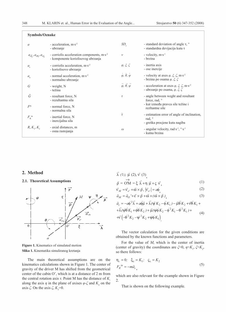
Figure 1. Kinematics of simulated motionSlika 1. Kinematika simuliranog kretanja
The main theoretical assumptions are on the kinematics calculations shown in Figure 1. The center of gravity of the driver M has shifted from the geometrical center of the cabin O’, which is at a distance of 2 m from the central rotation axis τ. Point M has the distance of K1 along the axis η in the plane of axises φ-ζ and K2 on the axis ζ. On the axis ζ, K3=0.
(1)
(2)
(3)
λ µ ν
ρ ξ λ η µ ς ν
(2), (3)
= O'M =
( ),1→
+ + ,
ν ν ω ρ ν φM o o a= + × =' '
a aM O= + × + × ×' ( )ε ρ ω ω ρ
a a a K K K Kc = − + + − − + +
+
φ λ φµ λ ψ φ µθ νθ
λ ψ
22 1 2 1( )
(
θ φθ µ ψφ φ θ
ν θ ψ ψφ
K K K K K
K K K1 2 2
21
21
22
22
+ + − − +
+ − − +
) ( )
11( )
(4)
The vector calculation for the given conditions are obtained by the known functions and parameters.
For the value of M, which is the center of inertia (center of gravity) the coordinates are ζ=0, η=K1, ζ=K2, so there follows:
η ξ ςc
Rin
c
K K
F ma
= = =
= −
0 1 2; ;
c c
(5)
which are also relevant for the example shown in Figure 2.
That is shown on the following example.
. . .
.. .. ..
–
,,
,,
.
,

Strojarstvo 50 (1) 347-352 (2008) M. KLARIN et. al., Human Error in the Evaluation of the Angle... 349Human Error in the Evaluation of the Angle... 349 349
φ φ
φπ
θ
= → =
= = =
=
const
a R
const
s m
-1
0
32,
→→ =
=
= → = =
s
-1
θ
θπ
ψ ψ
0
90 1const K 00 2
100 32
,
,
m
s m-1ψ
π= =K
a a K K K K
a Kc = − + − + + +
+ − +
λ φ ψ φ ψθ φθ
µ φ θ ψ
( )
(
22 1 1 2
2
φ φ θ
ν θ θ ψ ψφ
λ
K K K
K K K K
a ac
22
12
1
12
22
2 1
− − +
+ − − +
= −
)
( )
( φφ ψθ φθ µ ψφ φ θ
ν θ ψ
21 2 2
21
21
22
22
+ + + − − +
+ − −
K K K K K
K K
) ( )
( ++
= − + + = −
= − −
ψφ
ξ
η
K
a
ac
c
1
2 19 0 02 0 11 2 06
0 1 0 22 0
)
, , , ,
, ,
2
m/s
,, ,
, , ,
02 0 14
0 03 0 03 0 06 0
= −
= − − + =
m/s2
ac ς
G m a a a g
mG m
c c c= + + + =
= + + +
= ⋅ [
ξ η ς2 2 2 2
2 2 2 22 06 0 14 0 9 81
10 02
, , ,, N]] (6)
Figure 2. Example for the the center of gravity of the human body (the point M)Slika 2. Primjer za centar gravitacije čovjekova tijela
2.2. Experimental research device
The person in conditions of driving feels the changes in the intensity of force, i. e., acceleration. By his visual senses, his vestibulary structure and skeleton and muscle structure, the driver is able to evaluate the direction of the gravitation force.
Just how big the errors of the driver are in determination of the direction of the gravitation force, i. e., the horizontal plane in conditions of driving the vehicle, is possible to determine by simulations Klarin and Cvijanovic [4].
With that aim in mind, in our experiment a device has been used which has been specially constructed for the purpose of research in the field of aviation. It satisfies all the requirements with regard to simulation of driving a vehicle in curves in the road. Its sketch, which has been presented in Figure 3, shows that the driver has a cabin with instruments which have the option of rotary motion in all three planes of the coordinates system.
ϕ
ξ
ξ
η
η
ς
ς
Mainpivot
Hand
Cabin
Figure 3. Device for pilot accommodation to space disorientationSlika 3.Simulator prostorne dezorijentacije ispitanika
2.3. Experimental Research Description and Results
On the basis of these calculations, it can be concluded that for an assumed simple case with constant angle velocity of rotation along the axes, the result in point M, the center of gravity of the human body, is the centrifugal acceleration which diverts force G=mg from the vertical plane and also gives the resultant G . Since more complex motions and accelerations, which unavoidably occur, have an impact on the vestibulary structure of the natural person, which is located in the middle ear of the person, this is a more complex question than the team of researchers had anticipated, and the experiment was conducted in the manner in which the system was given only the constant angular movement around the axis φ of ω=40%, with a constant inclination of the cabin in the direction of movement of the vehicle of +/- 10° as shown in Figure 4.
,
,,
,,
,
.
350 M. KLARIN et. al., Human Error in the Evaluation of the Angle... Strojarstvo 50 (6) 347-352 (2008)
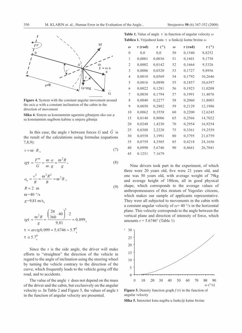
Figure 4. System with the constant angular movement around the axis φ with a constant inclination of the cabin in the direction of movementSlika 4. Sistem sa konstantnim ugaonim gibanjem oko ose φ sa konstantnim nagibom kabine u smjeru gibanja
In this case, the angle τ between forces G and G is the result of the calculations using formulas (equations 7,8,9):
v R= ⋅ω (7)
tg FG
m am g
Rg
mτ
ω= =
⋅⋅
=2
(8)
a vR
RR
R
R
g
n = = =
=°
2 2 22
2409 81
ωω
ω m
= /s= , m/s
(9)
tg Rg
arctg
τω
π
τ
= =⋅
⋅
=
= = ≈
2
22360
40 2
9 810 099
0 099 5 6746 5
,,
, , .77
5 7
0
0τ ≅ .
Since the τ is the side angle, the driver will make efforts to “straighten” the direction of the vehicle in regard to the angle of inclination using the steering wheel by turning the vehicle contrary to the direction of the curve, which frequently leads to the vehicle going off the road, and to accidents.
The value of the angle τ does not depend on the mass of the driver and the cabin, but exclusively on the angular velocity ω. In Table 2 and Figure 5, the values of angle τ in the function of angular velocity are presented.
Table 1. Value of angle τ in function of angular velocity ωTablica 1. Vrijednost kuta τ u funkciji kutne brzine ω
ω τ (rad) τ ( 0 ) ω τ (rad) τ ( 0 )0 0,0 0,0 50 0,1540 8,82521 0,0001 0,0036 51 0,1601 9,17582 0,0002 0,0142 52 0,1664 9,53263 0,0006 0,0320 53 0,1727 9,89564 0,0010 0,0569 54 0,1792 10,26465 0,0016 0,0890 55 0,1857 10,63976 0,0022 0,1281 56 0,1923 11,02087 0,0030 0,1794 57 0,1991 11,40768 0,0040 0,2277 58 0,2060 11,80039 0,0050 0,2882 59 0,2129 12,1986
10 0,0062 0,3558 60 0,2200 12,624515 0,0140 0,8006 65 0,2566 14,702220 0,0248 1,4230 70 0,2954 16,925425 0,0388 2,2228 75 0,3361 19,255930 0,0558 3,1991 80 0,3795 21,675935 0,0759 4,3505 85 0,4218 24,165640 0,0990 5,6746 90 0,4661 26,704145 0.1251 7.1679
Nine drivers took part in the experiment, of which three were 20 years old, five were 21 years old, and one was 50 years old, with average weight of 79kg and average height of 180cm, all in good physical shape, which corresponds to the average values of anthropomeasures of this stratum of Yugoslav citizens, which makes our sample of applicants representative. They were all subjected to movements in the cabin with a constant angular velocity of ω= 40 °/s in the horizontal plane. This velocity corresponds to the angle between the vertical plane and direction of intensity of force, which amounts τ = 5.6746° (Table 1)
Figure 5. Density function graph f (τ) in the function of angular velocity
Slika 5. Intenzitet kuta nagiba u funkciji kutne brzine
ω (°/s)
,
,
,
,
,
,,
Strojarstvo 50 (1) 347-352 (2008) M. KLARIN et. al., Human Error in the Evaluation of the Angle... 351Human Error in the Evaluation of the Angle... 351 351
Eight conditions of driving have been simulated. First of all, rotation was performed in the direction of the hand of the clock, simulating the right curve, and then in the opposite direction, i. e., simulation of movement in the left curve.
In the case of both directions, an uphill movement with a 10° gradient was firstly simulated in such a way that the cabin of the simulator was inclined with its front end for 10° upward. With the opposite inclination of the cabin the downward movement - downhill at 10° was simulated.
In all the previous four variations of simulation of driving, driving with visual control instruments and also without them was simulated.
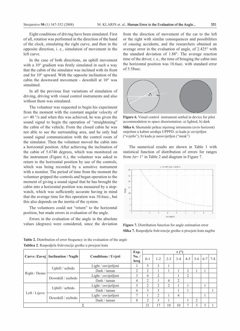
The volunteer was requested to begin his experiment from the moment with the constant angular velocity of ω= 40 °/s and when this was achieved, he was given the sound signal to begin the operation of “straightening” the cabin of the vehicle. From the closed cabin he was not able to see the surrounding area, and he only had sound signal communication with the control room of the simulator. Then the volunteer moved the cabin into a horizontal position. After achieving the inclination of the cabin of 5.6746 degrees, which was monitored on the instrument (Figure 6.), the volunteer was asked to return to the horizontal position by use of the controls, which was being recorded by a sensitive instrument with a monitor. The period of time from the moment the volunteer gripped the controls and began operation to the moment of giving a sound signal that he has brought the cabin into a horizontal position was measured by a stop-watch, which was sufficiently accurate having in mind that the average time for this operation was 10.6sec., but this also depends on the inertia of the system.
The volunteers could not “return” to the horizontal position, but made errors in evaluation of the angle.
Errors in the evaluation of the angle in the absolute values (degrees) were considered, since the deviation
from the direction of movement of the car to the left or the right with similar consequences and possibilities of causing accidents, and the researchers obtained an average error in the evaluation of angle, of 2.425° with the standard deviation of 1.88°. The average reaction time of the driver, i. e., the time of bringing the cabin into the horizontal position was 10.6sec. with standard error of 5.58sec.
Figure 6. Visual control instrument settled in device for pilot accommodation to space disorientation: a) lighted, b) darkSlika 6. Shematski prikaz mjernog istrumenta (avio horizont) smješten u kabini uređaja UPPPD: a) kada je osvijetljen (“svjetlo”), b) kada je neosvijetljen (“mrak”)
The numerical results are shown in Table 1 with statistical function of distribution of errors for ranges from ∆τ= 1° in Table 2 and diagram in Figure 7.
Figure 7. Distribution function for angle estimation errorSlika 7. Raspodjela frekvencije greške u procjeni kuta nagiba
Table 2. Distribution of error frequency in the evaluation of the angle Tablica 2. Raspodjela frekvencije greške u procjeni kuta
Curve /Zavoj Inclination / Nagib Conditions / UvjetiExp. No. / broj
τ (°)
0-1 1-2 2-3 3-4 4-5 5-6 6-7 7-8
Right / DesnoUphill / uzbrdo
Light / osvijetljeni 1 5 3 1Dark / taman 2 2 1 1 1 2 1 1
Downhill / nizbrdoLight / osvijetljeni 3 4 2 1 2
Dark / taman 4 2 1 4 2
Left / LijevoUphill / uzbrdo
Light / osvijetljeni 5 2 2 2 1 1 1Dark / taman 6 3 3 1 1 1
Downhill / nizbrdoLight / osvijetljeni 7 1 2 1 4 1
Dark / taman 8 2 3 1 1 2Σ 21 17 10 10 7 3 3 1
352 M. KLARIN et. al., Human Error in the Evaluation of the Angle... Strojarstvo 50 (6) 347-352 (2008)
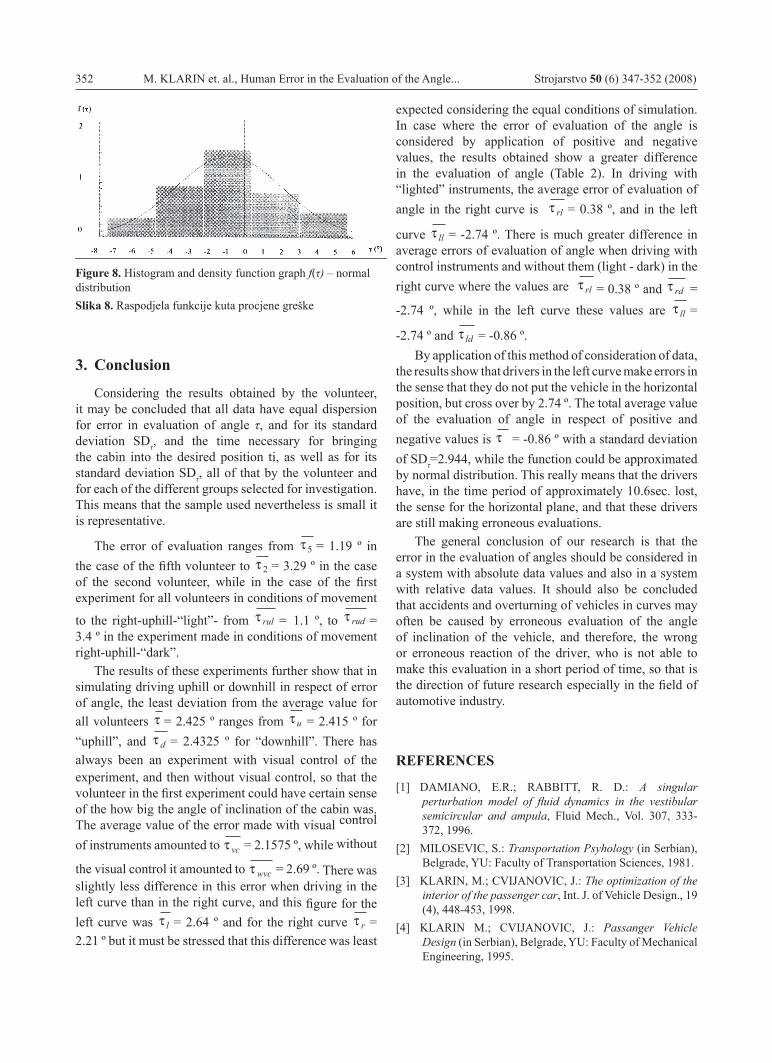
Figure 8. Histogram and density function graph f(τ) – normal distributionSlika 8. Raspodjela funkcije kuta procjene greške
3. Conclusion
Considering the results obtained by the volunteer, it may be concluded that all data have equal dispersion for error in evaluation of angle τ, and for its standard deviation SDτ, and the time necessary for bringing the cabin into the desired position ti, as well as for its standard deviation SDτ, all of that by the volunteer and for each of the different groups selected for investigation. This means that the sample used nevertheless is small it is representative.
The error of evaluation ranges from τ 5 = 1.19 º in the case of the fifth volunteer to τ 2 = 3.29 º in the case of the second volunteer, while in the case of the first experiment for all volunteers in conditions of movement
to the right-uphill-“light”- from τ rul = 1.1 º, to
τ rud = 3.4 º in the experiment made in conditions of movement right-uphill-“dark”.
The results of these experiments further show that in simulating driving uphill or downhill in respect of error of angle, the least deviation from the average value for all volunteers
τ = 2.425 º ranges from
τ u = 2.415 º for
“uphill”, and τ d = 2.4325 º for “downhill”. There has always been an experiment with visual control of the
experiment, and then without visual control, so that the volunteer in the first experiment could have certain sense of the how big the angle of inclination of the cabin was. The average value of the error made with visual control
of instruments amounted to τ vc = 2.1575 º, while without
the visual control it amounted to τ wvc = 2.69 º. There was slightly less difference in this error when driving in the left curve than in the right curve, and this figure for the left curve was τ l = 2.64 º and for the right curve τ r = 2.21 º but it must be stressed that this difference was least
expected considering the equal conditions of simulation. In case where the error of evaluation of the angle is considered by application of positive and negative values, the results
obtained show a greater difference in the evaluation of angle (Table 2). In driving with “lighted” instruments, the average error of evaluation of angle in the right curve is τ rl = 0.38 º, and in the left
curve τ ll = -2.74 º. There is much greater difference in average errors of evaluation of angle when driving with control instruments and without them (light - dark) in the right curve where the values are τ rl = 0.38 º and
τ rd = -2.74 º, while in the left curve these values are
τ ll =
-2.74 º and τ ld = -0.86 º.By application of this method of consideration of data,
the results show that drivers in the left curve make errors in the sense that they do not put the vehicle in the horizontal position, but cross over by 2.74 º. The total average value of the evaluation of angle in respect of positive and negative values is τ = -0.86 º with a standard deviation of SDτ=2.944, while the function could be approximated by normal distribution. This really means that the drivers have, in the time period of approximately 10.6sec. lost, the sense for the horizontal plane, and that these drivers are still making erroneous evaluations.
The general conclusion of our research is that the error in the evaluation of angles should be considered in a system with absolute data values and also in a system with relative data values. It should also be concluded that accidents and overturning of vehicles in curves may often be caused by erroneous evaluation of the angle of inclination of the vehicle, and therefore, the wrong or erroneous reaction of the driver, who is not able to make this evaluation in a short period of time, so that is the direction of future research especially in the field of automotive industry.
REFERENCES
[1] DAMIANO, E.R.; RABBITT, R. D.: A singular perturbation model of fluid dynamics in the vestibular semicircular and ampula, Fluid Mech., Vol. 307, 333-372, 1996.
[2] MILOSEVIC, S.: Transportation Psyhology (in Serbian), Belgrade, YU: Faculty of Transportation Sciences, 1981.
[3] KLARIN, M.; CVIJANOVIC, J.: The optimization of the interior of the passenger car, Int. J. of Vehicle Design., 19 (4), 448-453, 1998.
[4] KLARIN M.; CVIJANOVIC, J.: Passanger Vehicle Design (in Serbian), Belgrade, YU: Faculty of Mechanical Engineering, 1995.