Embed Size (px)
Citation preview
HUMAN BODY S IMULATIONS FOR ANALYS ! S OF A I RCRAFT CRASH SURV I VABIL I TY
by
0 . H . Laananen S imu l a Inc . , Tempe , Ar i zona , U . S . A .
I ntroduct ion
There a re three major considerat i ons i n des i g n i ng c rashworthi ness i nto a vehi c l e s tructure whether the veh i c l e i s to be used on l and o r i n the a i r . The fi rst i s to ensure tha t suffi c i ent l i v i ng space i s ma i nta i ned dur ing impact . The second i s to restra i n the occupants to prevent i njuri ous contact wi th the veh i c l e i nter i o r or ejecti on from the veh i c l e ; i mpl i c i t i n th i s requi rement i s the need to reta i n the seat i n the veh i c l e as wel l as keep the occupant i n the sea t . The thi rd i s to attenuate the forces expe ri enced by the 0:.:cupant t:: a tol erabl e 1 eve1 .
The a i rcraft crash envi ronment presents prob l ems that can make protect i on of occupants part i cu l ar ly d i ff i cu l t . For exampl e , the peak vertica l acce l era t i on present i n a crash may exceed the l evel that the human body can tol erate i n a d i rect i on para l l el to the s p i ne wi thout i n jury . I n l i ght a i rcraft i t i s genera l ly not practi ca 1 t o des i g n suffi c i ent energy-absorbi ng capabi l i ty i nto the l ower a i rframe s tructure to protect the occupant aga i n st these vertical forces , a s the prerequ i s i te cru sh space i s not ava i l ab l e . Inc l u d i ng some mechan i sm for energy absorpti on i n the seat st�uctu re of such an a i rcraft cou l d reduce occupant i njury in a c ra s h . Howeve r , not only does pred i c t i on of the seat s tructu re response to dynami c l oa d i ng present a compl ex engi neer ing probl em , but gross overa l l deformation of the seat fu rther compl i ca tes restra i nt system des i gn i n most l i ght a i rcraft where the l ap o r shoul der bel ts a re often attached to the a i rcraft s tructu re . Because dynam i c i nteract i cin of the sea t , occupant , and res tra i n t system i s too compl ex for ana lys i s by manual techn i ques , the des i gn process shou l d be suppo rted by computer s imu l a t i o n , a l though fi nal eva l uat ion of a cra shworthy des i gn must i nc l ude fu l l -sc a l e dynam i c tes t i n g .
Th i s paper w i l° l rev i ew spec i fi c req u i rements for both mathemat i ca l and mechan i cal model s i n the eval uati on o f a i rcraft seating and restra i nt systems , and present a .th.re.�-dimens i onal mathemat i ca l s imu l a t i on of the human body , •,vh i c h has been deve l oped primari ly for ana lys i s of a i rcraft crash surv ivab i l i ty .
Eva l uat ion of Ai rcraft Seat i ng Systems
Des i g n pri nc i p l es and cr i teria for a i rcraft seats and restra i nt systems a re presented i n the Ai rcraft Crash Surv i va l Des ign Gu i de ( l } * , wh i ch was or i g i n a l l y publ i s hed i n 1 967 and has been updated several times . The most recent rev i s i on i nc l udes resu l ts of rnore than a decade ' s research and des i gn experi ence . lt descr i bes des i rab l e s trength and deformat i on characteri s t i cs , materia l sel ect i on , a ttachment to the a i rframe s tructu re , cush ion properti e s , energy-�bsorb i n g
*Numbers i n parentheses i ndi cate references l i s ted a t end o f paper .
9 5

mechani sms , restra i n t system confi gurati ons and characteri stics , and means for system eva l uation by analys i s and testi ng .
Cri teri a for crashworth i ness are al so conci se ly stated i n a mi l i tary speci fi cat i on , M IL-S-58095 ( 2 ) . Key requ i rements perta i n i ng to cras hworth i ness are m i n i mum stat ic strengths and l im i ts o n the seat ' s l oad-deformat i on characteri st ics i n the l on g i tud i na l , l ateral , and verti cal d i recti on s . Prov i s i on must be mactc for energy absorption i n the vert i ca l d i recti o n , and the energy-absorb i ng mechan i sm is requi red to protect occupants rang i ng i n s i ze between the 5th and 95th percenti l es from experi enci ng accel erations i n excess of human tol e rance. An obvi ous probl em i n des ign i ng for the two extremes of occupant we i ght i s to prov ide suff i c i ent strok i ng d i s tance for the 95th percent i l e wh i l e ensur ing that the 5th percenti l e , uti l i z i ng a s horter strake d i stance , wi l l not suffer excess i ve accel erat i o n . The s pec i fi ed compromi se sets the energy absorber l im i t l oad for a static l oad factor of 1 4 . 5 G , based on the combi ned weight of the 50thpercent i l e occupant and movabl e part of the seat .
The performance of a seat des i gned i n accordance w i th MI L-S-58095 i s eva l uated by means of s i x static tests and two dynami c tests . Both dynam i c tes ts ut i l i zc a 9 5th-percenti l e anth ropomorph i c dummy and are conducted accord i ng to the cond i t i ons i l l u strated i n Fi g . l . Both demonstrate the structural i ntegri ty of the seat under s imu l ated c rash cond i ti on s . Furthermore , in the fi rst test the energy-absorb i ng mechan i sm i s requ i red to ma i nta i n the accel e rati on measured on the seat bel ow a s pec i f i c l evel . For examp l e , the vertica l accel erati on component shou l d be l e s s than 23 G for du rati ons in excess of 0 . 006 sec .
TEST CONDITIONS AND SEAT ORIENTATION
TEST 1 : TEST 2: DOWNWARD, FORWARD, AND FORWARD AND LATERAL LOADS
LATERAL LOADS
DUMMY INERTIA LOAD Y
INERTIA
LOAD
TEST PULSE REOUIRED
48 G -CHANGE IN
A VELOCITY -� 15.2 M/SEC
-1 °siis I +-
CHANGE IN 30 G A VELOCITY -� 1 5.2 M/SEC
-1 °sMb3 1--
Fi g . l . Oynami c test requi rements ( 2 ) .
: . 0
A s hortcom i ng of the tol erancebased cri terion l i es in the fact that the measured response of the sea t i s a funct i on of the dynami c characteri sti cs of the coupl ed seat-occupant system , i . e . , di fferent occupant cha racteri s t i es produce di fferent seat response . Exi s t i ng dumm i es probabl y prov ide a real i s t i c test of seat and restra i n t system strength , but thei r characteri s t i c dynami c response to vert i cal i n puts has been shown to d i ffer s i g n i f i cant ly from human res ponse . An avi ation test dummy , posses s i ng more humanl i ke response to verti cal i n put , and i nc l ud i ng some means for di rect pred i ction of one or more i nju ry modes , such as by a force transducer in the l umbar regi o n , i s needed .
Even when a dummy for a i rcraft use i s ava i l abl e , such a dev i ce can on ly be emp l oyed practica l ly i n the eval uation of a compl eted des i g n , and cannot repl ace mathematica l s imu l ati ons duri ng devel opment . Such s imu l a t i ons shou l d , i deal l y , y iel d humanl i ke response regard l ess o f the impact cond i ti o n s . They shou l d prov i de real i s t ic estimates of l oad i ng on the seat and restra i nt system , as wel l as
96
measur i ng i nJ u ry potent ia l i n typ i c a l a i rcraft crash envi ronments . The devel opment of a computer s imu l at i on i n tended to achi eve these goa l s i s descri bed i n the fo l l ow ing sect i on s .
Mathema t ica l S imu l a t i on for C r a s n An a l v s e s
A number of dynam i c mode l s of the human body have been devel oped for crash surv i vabi l i ty a na lys i s . These r.1odel s vary i n compl exi ty and possess from 1 to 40 degrees of freedom . One-d imens i onal model s have been u sed i n pred i ct i on of human body response to an ej ecti on seat f i r i ng wh i c h , i f the body i s t i ght ly restra i ned , can be approximated as a one-dimens i onal phenomenon . Howeve r , a vehic le crash genera l l y i nvol ves a hor izontal component o f decel eration wh i c h forces rotat ion of body segments wi th respect to each other. I f no l a teral component of dece l eration is present , a two-dimens i ona l model wi l l suffi ce , provi ded the res tra i n t system i s symmetr i ca l . The di agonal shou l der be l t that , combi ned wi th a l ap bel t , i s often used in l i ght a i rcraft i s a s symmetr ica l and may cause l ateral mot i on of the occupant even i n the absence of a l a teral decel eration . The refore , a model that i s genera l l y usefu l i n restra i nt system eva l uat i on must be capabl e of pred i c t i ng three-d imen� i onal mot i o n , and several three-dimens i ona l ki nemat i c mode l s , cons i s t i ng of i n terconnected r i g i d l i n k s , have been devel oped ( 3- 6 ) . These mode 1 s and severa 1 deve 1 oped fo r pred i et i ons of head , s p i na 1 , and thorac i c i nj u ry a re d i scussed and compared i n Ref . 7 .
I n 1 9 7 2 , the U . S . Depa rtment of Tran s portat i o n , Federal Av i ati on Adm i n i s tration ( FAA) , i n i t i a ted a program to prov i de a prac t i ca l eng i neeri ng tool for use i n the des i g n and eva l uat ion o f seats and res tra i nt systems for l i ght a i rcraft . Th i s program i nc orporated a dynami c model of the human body comb i ned wi th a fin i te e l ement model of the seat structure, i n tended to enab l e the des i gner to ana l yze the s tructural el ements of the seat as wel l as eva l uate the dynam ic response of the occupant during a cra s h . The d i g i tal computer program ba sed on th i s model is c a l l ed SOM-LA ( Seat/Occupant Mode l - L i g ht Ai rcraft ) . Because the goal i n the devel o pment of th i s program was to a s s i s t engi neers whose funct i on i s seat and/or restra i nt system des i g n , a number of user-ori ented features were i ncl uded to faci l i tate operat ion by m i n imi z i ng the quant i ty of i n put data req u i red , parti c u l ar ly i n regard to those data that m i ght not be read i ly ava i l a b l e t o a n engi neer i n the a i rcraft i ndustry . For exampl e , d imen s i ons and i nertia l properti es for 1 1 s tandard 1 1 occupa n t s , a 50th-percenti 1 e human ma 1 e and a 50thpercent i l e anthropomorph i c test dummy , were i nc l uded i n the program so that they cou l d be read i ly sel ected by the u ser .
Th i s ori g i na l model was descri bed i n a comprehens i ve tech n i ca l report publ i s hed by the FAA i n 1 9 75 ( 8 ) . Mod i f i cat ions have been made to the model s i nce then to improve s imu l a t i on qua l i ty and to prov i de i ncreased capabi l i ty and add i t i onal des i rab le output . In that i n ter im , a test i ng program was i n i t i a ted by the FAA C i v i l Aeromed i ca l I n s t i tute ( CAMI ) to prov i de data for va l i d at i o n of the model . A l though work on model improvement and va l i da t i on i s conti n u i n g , the rema i nder of th i s paper wi l l descr i be the present mode l , i ts va l i d a t i on , and success to date in mode l i ng a ctual systems .
Seat/Occupan t Mathemat i c a l Model
The occupa n t i s mode l ed by el even mass segments as i l l u s trated i n Fi g . 2 . The torso a nd head segments are connected by beam e l ements that possess axi a l , fl exu ral , and tors i onal sti ffnes s . The h i p and shoul der j o i nts are of the bal l -andsocket type , each possess i ng three rotat i o na l degrees of freedom . The e l bow,
9 7

N E C K ELEMENT
S SEGMENT MASS C E N T E R 0 J O I N T CD·®···„·®
X
Fi g . 2 . El even-segment occupant mode l .
knee , a nd head-neck j o i nts perm i t h i nge-type moti on . In total , the model possesses 31 degrees of freedom for s i mu l at ion of a human subject . For s imu l at ion of a dummy, one degree of freedom i s removed by l oc k i ng the head-neck jo int so that mot i on of the head rel at ive to the torso i s determi ned sol el y by deformat i on of the neck e l emen t .
Jo i nt Res i s tance . Rotat ion of the body jo i nts i s control l ed by v i scous dampers and non l i near tors i onal spri ngs . The damp i ng coeffi c i ent for each j o i n t 1 s constant in al l cases , but the spri ng moments depend on the user ' s cho ice of human or dummy occupant . For s imu l at ion of a h uman occupant , they a re zero throughout the normal range of j o i nt rota t i o n , but i nc rease rap i d ly at the l im i t i n g angul a r d i spl a cements . For s imu l at i on of an anthropomorph i c dummy , constant ( nonzero ) fri cti ona l moments are appl i ed throughout the normal range of moti o n ; these torques i ncrease to hi gher va l ues to l i m i t the rotati on , j ust as in the case of the human occupa n t .
Externa l Forces . The externa l forces that act on the el even body segments can be characteri zed as e i ther contact forces or res tra i nt force s . The contact forces a re the forces exerted by the cush i ons , the fl oor , and an optional i nf latab l e restra i nt . Each of these forces is c a l c u l ated by f i rst determ i n i n g , from occupant d i spl acement , the penetration of a r i g i d contact s urface fi xed to a body segment i nto e i ther a cush ion or the f loor . Us i ng th i s deformati on , the force i s then computed from a tabl e of forces and defl ections that i s provi ded as i nput data . Effects of non l i near un l oad i n g , hysteres i s , and rate sen s i t i v i ty are consi dered .
98

The method used i n ca l cul at ing the forces exerted on the body by the res traint system d i ffers somewhat from that used for the contact force s . The pri nci pa l di fference i s that the restra int forces do not act at any fi xed po i nts on the body , but , rather , the po i n ts of appl i cation depend on cu rrent be l t geometry. The five ava i l ab l e restra i n t system configurati ons cons i s t of a l ap bel t al one or combi ned wi th a s i ng l e di agonal bel t , over ei ther shoulder, or a doubl e shoul der bel t , wh ich may i nc l ude a l ap be l t ti edown strap . The restra i nt l oads a re transmi tted to the occupant through el 1 i psoidal su rfaces fi xed to the upper and l ower torso segments . The l ocati ons of the anchor po i nts on ei ther the seat or the a i rframe structure and of the buck l e connect ion are determined by user i nput a l ong wi th webbi ng properties . The effect of i n i ti a l s l ack or prel oad i n the system i s con s i dered .
For both the upper and l ower torso restra i nts , the forces are determi ned i n the same manne r . Fi r st , the bel t l oads a re c a l c u l a ted from the d i spl acements o f the torso surfaces rel at i ve to the anchor po i nts . The n , the resu l tant force on each segment i s cal cul ated and appl i ed at the poi nt al ong the arc of contact between the be l t and the el l i psoida l su rface where the force i s normal to the su rface .
The capabi l i ty of the bel ts to move rel a t i ve to the torso surfaces a l l ows s imul at ion of 11 s ubmar i n i ng 11 under the l ap bel t , an important cons i de rat ion i n des ign of a seat and restra i nt system .
Occupant Phys ical Propert i es . Because i t has been as sumed that the pri nc ipal user of this program is i n terested ch i efly i n the seat or restra i nt system, a m i n imum of informat i on i s requ i red to des c r i be the occupa n t . Input data i ncl ude the se l ect ion of human or dummy , the ma i n di fference be i ng the jo i nt model , as d i scus sed earl i er . The d imens i ons and i nert ia l properti es for 1 1s tandard11 occupants , a 50th-percent i l e c i v i l ian ma l e and a 50th-percenti l e anthropomorph i c dummy, are i nc l uded i n the program . The segment l engths , mas ses , center-of-mass l ocati ons , and moments of i nertia for the human occupant model a re based on cadaver data reported i n Refs . 9- 1 1 , averaged and adjusted to approximate 50thpercenti l e val ues . Correspond i ng properties for the dummy model are based on the speci fications of U . S . Federal Motor Veh ic l e Safety Standard 208, Part 572 . Shou l d a user wi sh to s imul ate a l a rger or sma l l er occupant , provi s i on is made to i nput nonstandard propert i es .
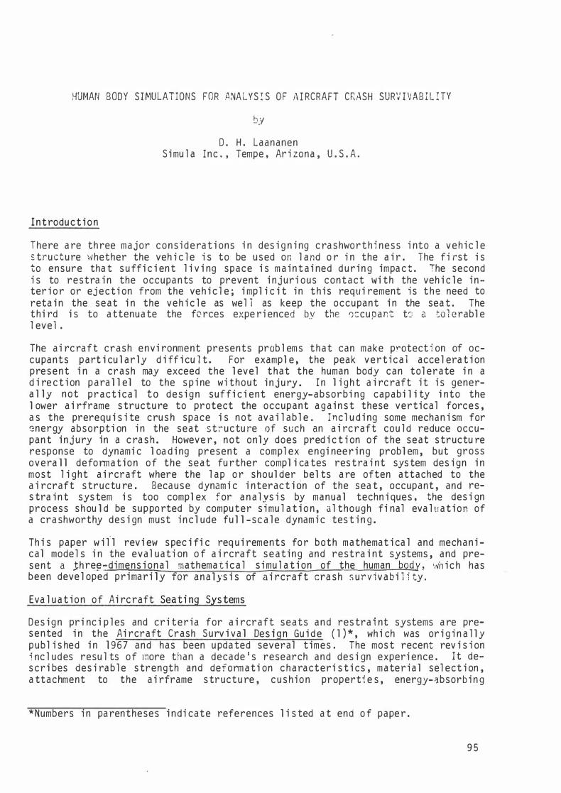
For cal cul ation of external forces exerted on the occupant by the seat cushi ons and restra i n t system and for pred i ct i on of impact between the occupant and the a i rcraft i n teri o r , 24 s urfaces are defi ned on the body. These surfaces are el -
4 2 0
5
2 4 18
Fi g . 3 .
1 5
Occupant mode l contact su rfaces .
1 i psoi d s , sphere s , and cyl i nders , as shown i n F i g . 3 . The d imen s i ons of these surfaces were obta i ned from an anthropometr i c study of the U . S . c i v i l i a n popu l ation ( 1 2 ) .
The ranges of jo int rotation that are used i n the program are based on the data of Oempster ( 9 ) and Gl anvi l l e and Kreezer ( 1 3 ) for the human occupant and FMVSS 208 for the dummy. For jo i nts where the al l owed range of rotat ion was found to depend on the axi s of rotation , the rotat ion about a l a teral axi s ,
99

wh i ch wou l d predomi nate i n a frontal impact , was con s i dered most important and i s u sed as the s i ng l e l i m i t i ng ang l e i n the model .
Seat Model . The seat model. uses a fin i te el ement anal ys i s procedure that i s based on expl i c i t , t imewi se numerical i n tegrat i on of the equati ons of moti on for the node po i n ts , as reported i n Ref . 1 4 . The techn i que perm i ts anal ys i s of the dynam i c res ponse of pl ate-beam s tructures i nvol v i ng very l a rge d i spl acements and rotat i ons , as wel l as el a s ti c-pl a st i c materia l behav i or . The capac i ty of thn structural model is approx imately 1 50 nodes , 1 50 e l ements , 5 materi a l s , and 1 0 beam cross sect i ons .
Because the sol u t i on step s i ze for the structural anal ys i s i s governed by the frequency content of the f i n i te e l ement mes h , the i nc l u s i on of short, sti ff e l ements may requ i re a step s i ze con s i derab l y sma l l er than that requi red for the occupant model . The computer program perm i ts repl a c i ng such e l ements w i th r i g i d l i n k s , thereby permi tt ing a l a rger s tep s i ze and great ly improv i ng eff i c i encv .
For use i n res tra i nt system or cab in configurati on ana l yses , where the deta i l s of seat res ponse may be immater ia l or seat de s i gn unknown , a r ig id seat mode 1 can be se lected . The r i g i d seat cons i sts of only seat pan and back, \<Jh i ch are fi xed rel a t ive to the a i rcraft , and i ts use s i gn i fi cantl y reduces computer time requ i red .
One type of seat that has been i ntroduced i n the crew stati ons of both c i v i l i a n ( 1 5) and m i l i tary ( 1 6 ) hel i copters to ach i eve improved crash surv i vab i l i ty i s the gu i ded energy-absorbi ng sea t . The sea t cons i s ts of a bucket to wh i eh the restra i n t system i s a ttached and a frame mounted on the a i rcraft floor or bu l khead . Pri nci pal funct i onal members of the frame are two vert ica l ( or nearl y verti ca l ) gu ide tubes a l ong wh i ch the bucket can move , control l ed by one or more energy-absorb i ng dev i ces . Vert i ca l i nert i a l crash l oads force the seat buckct do\'m the gu ide tubes aga i nst the res i s tance of the energy absorbers , produc i nq an energy-absorb i ng stroke i n that d i rect i o n . For most eff i c i ent use of thn stroke d i stance ava i l ab l e between the bucket and the fl oor, energy absorbers have been des i gned to stroke at constant l oad , that l oad be i ng determi ned by des i gn c r i teria based on human tol erance to ·+G accel erat i o n . Assumi ng that for anal ys i s of a gu i ded seat under crash cond i ttons the bucket and frame cou l d b� considered essent i a l l y r i g i d and a l l deformat i on concentrated in the energyabsorb i ng s troke , a s troki ng capabi l i ty i s i ncl uded as a degree of freedom i n the r i g i d seat opti o n . Because e l a s t i c bend i ng of the bucket and frame appear to i nf l uence seat and occupant response in dynami c test i n g , an addi ti onal degree of freedom was added to s i mu l a te rotati onal e l a s t i c i ty . The f i n i te el ement model i s capabl e of s imu l a t i ng such a sea t , u s i ng spri ng el ements for the energy absorbers , beams for the frame , and a comb inat ion cf beams and pl ates for t.hc bucket . However, such seats are typ i ca l ly desi gned wi th a frame of sti ff, h i ghstrength materi a l , as s i g n i f i cant deformat i on i n the frame or bucket m i ght impede the energy-absorbi ng s troke . The two-degree-of-freedom mode l can qu i tr. adequately s i mu l a te such a seat for a crashworth i ness ana l ys i s . The deta i l erl e l a s t i c response of the frame m ight then be more effi c i ent ly i nvestigated us i ng a general purpose , l i near fi n i te e l ement model subjected to static equ i va l e:-it. l oads determi ned from the dynam i c ana l ys i s .
Digi tal Computer Program
The d i g i ta l computer program ba sed on the seat and occupant model s i s 1·iri tten enti rely i n FORTRAN I V to i nsure a h i gh degree of compa t i b i l i ty wi th d i fferc��
100

computer systems , and during devel opment i t has been run on Control Data , IBM, and Uni vac systems .
Input data are read by the program i n the fol l owi ng seven categori es :
1 . Simu l ati on and output control i n fonnati o n . 2 . Cockpi t descri pti on . 3 . Cush ion propert i es . 4 . Restra i n t system descri pti on . 5 . Crash cond i ti ons . 6 . Seat des i g n data . 7 . Occupant descri pti on .
Output data cons i s t of 1 0 bl ocks of i n fonnat i on that are sel ected for pri nti ng by user i nput . The data i ncl ude t ime h i s tori es of the fol l owi ng vari a b l e s , wh i c h are stored duri ng sol ut ion at predetenni ned print i nterval s for output i n both d i g i tal and p l ot fonn :
1 . Occupant segment pos i t i ons ( X , Y , Z , pi tch , and rol l ) . 2 . Occupant segment ve loc i t ies ( X , Y , and Z) . 3 . Occupant segment accel erations ( x , y , z , and resul tants ) . 4 . Restra i nt system l oads ( tens i l e l oads i n webb i ng and resu l tant normal
l oads on the pe l v i s and ehest ) . 5 . Cush ion l oads . 6 . Ai rcraft di spl acement , vel oc i ty , and accel eration . 7 . Di spl acements and s tresses at se lected node s . 8 . Fl oor reacti ons ( forces and moments ) . 9 . Contact between the occupant and the a i rcraft i nteri or .
1 0 . Injury cri ter i a and ax ia l force i n the l umba r spi n e .
The i njury cri teria used i n the program are a l l computed from segment acce l e rat i on s . The Dynam i c Response I ndex ( DR I ) prov i des an i nd icat ion of the probab i l i ty of spi nal i njury due to a vertica l accel e rati on para l l el to the s p i ne ( 1 7 ) . It i s computed from the response of a s i ng l e-degree-of-freedom , damped spri ngmass model , wh i ch is dri ven by the component of pel v ic accel erati on para l l el to the spi n e . The ax ia l l oad i n the l umbar s p i ne i s pri n ted , as are the Severi ty I ndexes ( S I ) for the ehest and head , and the Head Injury Cri terion ( H IC ) of Federal Motor Veh i c l e Safety Standard 208 . Al so , the pred i cted vel oci ty and po i nt of impact for contact between a n occupant segment a nd the a i rcraft i nterior can prov ide i nfonnat ion for des ign of energy-absorb i ng surface , i ncl udi ng protective padd i ng a nd col l ap s i b l e s tructure under the padd i n g .
Execut i o n t ime for the program varies somewhat from one case to another because of i ts vari a b l e s tep s i ze i ntegrat ion method , but typical t imes can be c i ted for a sampl e cas e . Simu l at ion of a 1 5 . 2-m/sec impact l i ke the drop test of MIL-S-58095 for a n event t ime of 0 . 1 sec u s i ng the energy-absorbi ng r i g i d seat option has consumed from 24 to 60 sec of central processor t ime on a CDC Cyber 1 75 system us i ng a three-d imensi onal sol u t i o n . Us i ng the opti ona l two-dimensi onal sol u t i on reduces the requ i red central processor t ime to between 4 and 8 sec for the same case .
Model Val idation
Val i dat ion of the combi ned seat-occupant model has been based on a test i ng program conducted at the FAA C i v i l Aeromed ica l I nsti tute ( CAMI ) . The tests used a n
101

Al derson V IP-50 dummy i n a forward-faci ng test seat wi th a restra i nt sys tem cons i s t i ng of a l ap bel t and two shoul der straps . The seats in the two test ser ics were structura l ly s impl e i n order to mi n im ize the number of test vari abl es wh i l e asses s i ng the model ' s capabi l i ty of s imu l a t i ng l arge , pl astic deformat ions . For each of those seats the seat pan and back cons i s ted of rel a tively r i g i d frames , para l l el and perpend i c u l a r to the f loor . In the fi rst seri es , the l egs were fabricated from steel p l a te 76 mm wide and 6 . 35 mm th i c k , such that seat deformat i on wou l d be confi ned to bend i ng about a l a teral ax i s and l oca l i zed at the top a nd bottom of the l egs . Two impact vector ori entati ons 1vere selected ; the first orientation prov ided pure forward-fac i ng ( -G ) accel erati o n . The second or ientat ion prov i ded combi ned l ong i tu d i na l ( - G ) 1ind vertical ( +G ) accel eration by reori ent i ng the seat system so that the �mpact force vector zfel l 60 deg bel mv the 11 fl oor11 p l ane of the seat. Each configuration was tested at two l evel s of accel erati o n , nomi na l ly 9 and 1 7 G, wi th an impact v e l oc i ty of about 1 3 . 4 m/sec . Tests were repeated u nt i l ten good data record i ngs were obta i ned for a l l measurements , so that the mean a nd s tandard dev i at i o n of the time h i s tory of the measurement cou l d be computed .
The second series of tes ts were accomp l i shed u s i ng a r i g i d seat wi th deformab le tubu l ar l egs , 25-mm di ameter and 2 . 2-mm 1·1a l l thi cknes s , repl aci ng the p l a te sections , in order to eval uate the abi l i ty of the model to pred i ct seat structural response in the presence of l oca l i zed deformation changi ng the cross-secti onal properties of cri ti cal structu ral e lements . Fi fty-e i g h t dynamic tests l'lere comp l eted i n the forward-fac i ng ( -G ) ori entations and wi th the fl oor ang l ed at 60 deg to prov i de a downward and fÖrward occupant react i on . Acce l e ration l evel s of 5 . 4 and 9 . 5 G prov ided m i n imal pl ast ic deformation (wi thout any s i gn i fi cant c ross section change) a nd marked p last ic deformat ion (wi th l ocal i zed buckl i ng a nd c ross section change at the fi xed end ) , respect ive ly , i n the -G ori entat i o n . I n the tes ts wi th the floor ang l ed , acce l erat ion l evel s of 1 3 .� and 2 2 G were requi red to pr�duce s im i l ar resul ts .
These val idat ion tests , wh ich a re descri bed i n deta i l i n Ref. 1 8 , i nd icated the des i rabi l i ty of several mi nor refi nements in the seat structural model . After these mod i fi cati ons have been compl eted , a th i rd seri es , u s i ng producti on a i rcraft seats of varyi ng comp l ex i ty wi l.l be cönducted .
The response of the occupant model a l one has been ver if ied and improved us i ng data from another series of dynamic tests conducted by CAMI as part of a compari son of three 50th-percenti l e dummy des i gn s ( 1 9 ) .
Because the on ly seats that have been desi g ned to date accord i ng to we l l -defined crashworth i ness cri ter ia have been gui ded energy-absorb i ng seats , accurate simul ation of such seats has been considered important . Usi ng the energy-absorbi n g 11 r i g i d 11 seat opti on , a drop test of a UH-60A Bl ack Hawk hel i copter crewseat , descri bed i n Ref. 1 6 , was s imul ated . The test confi gurati on , as shown i n Fi g . 1 , subjected the seat to combi ned downward , forward , a nd l ateral l oads , u t i l i z i ng a peak dece l erati on of 48 G , a vel oc i ty change of 1 5 . 2 m/sec , and an approximately equ i l a teral tri a ngu l a r dece l e rati on pu l se shape . The seat and mount ing trac ks were rotated in the drop cage through 30-deg nosedown p i tch a nd l 0-deg rol l to ach i eve the des i red l oad components . The test condi tions were s imu l ated us i ng both two- and three-dimens i onal occupant model s . For the t1·10-d imensi onal casr. both the rol l or ientation and the l a teral decel e rat ion component 1vere om i tted .
Fi g . 4 shows the occupant pos i ti o n , front and r i ght s i de v i ews , for a s imu lat ion of the B l ack Hawk crewseat test . At 65 msec the seat has stroked approx imate ly
102

T � 0.000
T = 0.065
T „ 0 . 0 9 3
Fi g . 4 . Computer s imu l at ion of Black Hawk crewseat drop test .
103

1 2 . 7 cm bel ow its i n i ti a l pos i ti o n , and at 93 msec , approximately 35 cm , actual ly bel ow the a i rcraft fl oor l evel . ( The Bl ack Hav1k hel i copter has a 1·1e l l i n the fl oor bel ow each crewseat to al l ow add i ti onal stroke . ) Seat stroke pred i cted by the computer s imul at ion i s compared i n Fi g . 5 w i th that measured i n the tes t . Acce l erat ion data al so compared qui te favorabl y . The verti cal component of the seat accel eration was of part i c u l a r i n terest i n the test because of its use in the seat cri ter ion ( M I L- S- 5809 5 ) as an i ndex of human tol erance . As shown i n Fi g . 6 , the measured data sho1·1ed peaks of 1 6 , 24, and 33 G at 2 2 . 3 4 , and 9 0 msec , respect i ve ly . The predi cted seat accel erat ion showed peaks o f 1 6 , 29 , and 30 G at 22 , 32 , and 90 msec , respect i ve ly . The three-d imensiona l · s imul a t i on produced occupant and seat di sp l acements that were s imi l a r to the output of the two-d imens i onal model .
tz w ::E w
3 0
0 2 0 < ....1 li. "' Q t-< 1 0 w "'
--- T E S T D A T A
0 0 0 P R E D I C T E D
0 0.
0;7 O'--����-'--����--c:;._���������,__���---'
0 0.02 0.04 O . O G 0 . 0 8 0 . 1 0 T l t.1 E , S E C
Fi g . 5 . Compari son of seat s troke measured i n drop test of B l ack Hawk crewseat wi th computer pred i c t i o n .
I n order t o a i d i n the devel opment of more ri gorous seat eva l uati on cri teri a , parti cu l a rly wi th respect to s p i nal i n j ury , a seri es of dynam i c tests v1i th human cadavers i n a B l ac k Hawk crewseat has been conducted . Compari son of the resu l ts of these tests wi th s i mi l ar dummy tests i nd i cated the need for s i g n i ficantly greater dampi ng for s imul a t i on of a human subject .
Conc l u s i on s
A mathematica l model of an a i rcraft seat and occupant has been deve l o ped for u se i n eval uat ion of the c rashworth i ness of a i rcraft seats and restra i nt systems . Program eff ic i ency and ease of user i nput have been g i ven cons i de rabl e we ight i n devel opment. Al though further val i dati o n , ba sed on te st i ng of more compl ex seats and crash envi ronments , i s needed to estab l i s h the effect i ve l i mi ts of the s imu l ati o n , the procedure has the advant.age of bei ng i ndependent of test data
10'1

4 0
3 0
c:J 2 0 z 0 1- 1 0 c( ex: w ..J w 0 <.> <.> c(
- 1 0
- 2 0 0
o O
0
T E S T D A TA 0 O O 0 P R E D IC T E D
0 0 0
0 . 0 2 0 . 0 4 T I M E , S E C
0 0
0
0 . 0 6 0 . 0 8 0 . 1 0
Fi g . 6 . Compar i son of vert ical component of seat pan acce l e ration measu red i n d rop test of Bl ack Hawk crewseat wi th computer pred i ction .
a nd requ i r i ng only i nformation that i s read i l y ava i l ab l e to the des i gner. Sati sfactory agreement of model pred i c t i ons wi th test data has been demonstrated , and the model i s con s i dered to be a potent ia l ly va l uabl e engi neeri ng tool for cra shworthy des i gn of a i rcraft.
References
1 . Desjard i ns , S . P . and Laananen , D . H . , 1 1Ai rcraft Crash Su rv i val Des i gn Gu i d e : Vol . I V - Ai rcraft Seats , Restra i n t s , Li tters , and Padd i ng , 11 Simul a Inc . , Tempe , Arizona , USARTL Techn i ca l Report 7"9-22D , Appl i ed Technol ogy Laboratory , U . S . Army · Research and Technol ogy Laboratori es ( AVRADCOM ) , Fort Eusti s , Vi rgi n i a , February 1 980.
2 . Mi l i tary Speci ficati on , MIL-S-58095 (AV ) , 1 1Seat System : Cra shworthy , Non- Ej ect i on , . Ai rcrew , General Speci ficati on for , 11 U . S . Department of Defense , Was h i ngton , D . C . , 2 7 August 1 971 .
3 . Bartz , J . A . , 1 1Development and Va l i dat ion of a Computer Simu l a t i on of a Crash V i ctim i n Three Dimens i on s , " Proceed i ngs of the S i xteenth Stapp Car Cra s h Conference , Soci ety of Automotive Eng i neers , New York , 1 972 , pp. 1 05- 1 27 .
4. Hus ton , R . L . , Hessel , R„ and Passere l l o , C . , 11A Three-Dimensi ona l Veh i cl e-Man Model for Col l i si on and H i g h Accel erat i on Stu d i es , 11 Soc i ety of Automot i ve Eng i neers , Paper No . 740275 , 1 9 74 .
5 . Robb i n s , D . H . , Bennett , R . 0 . , and Bowman , B . M . , 11 User-Ori ented Mathemati cal Crash Vi ctim Simu l ato r , " Proceed i ngs of the Si xteenth Stapp Car Crash Conference , Soci ety of Automot ive Eng i neers , New York , 1 9 72 , pp. 1 28-1 48 .
6 . Young , R . D . , 11A Three-Dimens i onal Mathemat ica l Model of an Automob i l e Passenger , 11 Texas Transportat ion I n s ti tute , Col l ege Stat i on , Texas , Research Report 1 40-2 , 1 9 70.
7 . Ki ng , A. I . and Chou , C . C . , 11Mathematical Model i ng , Simu l at ion and Experimenta 1 Test i ng of Bi omechani ca 1 System Crash Response , 11 Journa 1 of Bi omechani cs , Vol . 9 , 1 9 76 , pp . 301 -31 7 .
105

8 . Laananen , D . H . , " Devel opment of a Sc i en t i fi c Bas i s for Anal ys i s of Ai rcraft Seat i ng Systems , " Federal Av i ation Admin i strat i o n , Report No . FAA-RD-74- 1 30 , U . S . Department of Transportat i o n , Wa s h i ngton , D . C . , January 1 9 75 .
9 . Dempster, W . T. , " Space Requ i rements o f the Seated Operator , " �lri ght-Patterson A i r Force Base , Ohi o , TR55- 1 59 , Ju ly 1 955 .
1 0 . Dempster, W . T. and Gaughran , G. R . L . , " Propert i es of Body Segments Based on S i ze and We igh t , 11 Ameri can Journal of Anatomy, Vol . 1 20 , 1 967 , pp. 33-54 .
1 1 . Chand l e r , R . F . , et al . , " Invest igat ion of I nert i al Properties of the Human Body , 11 Aerospace Medica l Research Laboratory , Wright-Patterson A . F . B . , Oh i o , Report No . DOT-HS-01 7-2-31 5- l A , U . S . Department of Transportat i on , Washi ngton , D . C . , March 1 975 .
1 2 . Dreyfus s , H . , The Measu re of Man , Whi tney Publ i cat i ons , New York , 1 960 .
1 3 . Gl anv i l l e , A . D . and Kreezer , G . , "The Max imum Ampl i tude and Vel oc i ty of Jo int Movements i n Normal Ma l e Human Adu l ts , 11 Human B i o l ogy, Vol . 9 , 1 937 , pp . 1 9 7-21 1 .
1 4 . Yeung , K. S . and Wel ch , R . E . , " Refi nement of F i n i te El ement Ana lys i s of Automoti ve Structures Under Crash Load i ng , 11 I I T Research Ins t i tute , Ch i cago , I l l i n oi s , Report No . DOT-HS-803-466 , U . S . Department of Transpo rtation , Was h i ngton , D . C . , October 1 9 77 .
1 5 . Garri s on , J . R. and Wa l drup , H . H . , "The Bel l Model 222 , 11 Paper No. 770951 , presented at Aerospace Meet ing , Los Angel es , Cal i forni a , Soc i ety of Automot i ve Eng i neers , Inc . , 1 4- 1 7 November 1 97 7 .
1 6 . Desjard i n s , S . P . , e t al . , " Crashworthy Armored Crewseat for the UH-60A Bl ack Hawk , 11 paper presented at 35th Annual Nat i onal Forum of the Ameri can Hel i copter Soci ety , Was h i ngton , D . C . , May 1 9 79 .
1 7 . Bri nkl ey , J . W . , " Devel opment of Aerospace Escape Systems , " Ai r Un ivers i ty Rev i ew , Vol . X I X , July-August 1 9 68, pp . 34-49 .
1 8 . Chandl er , R . F . and Laananen , D . H . , " Seat/Occupant Crash Dynam i c Ana lys i s Val idati on Tes t Program , 11 Paper No . 790590 , presented at Bus i ness Ai rcraft Meeti ng , W ich i ta , Kansas , Soci ety of Automot ive Eng i neers , Inc . , Apr i l 1 9 79 .
1 9 . Mas s i ng , D . E . , Naa b , K . N . , and Yates , P . E . , " Perfonnance Eval uation of New Generation 50th Percen t i l e Anthropomorph i c Tes t Dev i ces : Vol ume I -Techni cal Repo rt , " Cal span Corporat i on , Buffa l o , New York , Report No . DOT-HS-801 - 431 , U . S . Department of Transportati on , Wa s h i ngto n , D . C . , March 1 9 75 .
106