Embed Size (px)
Citation preview
Human-Assisted Motion Annotation
Ce Liu1 William T. Freeman1 Edward H. Adelson1 Yair Weiss1,2
1 CSAIL MIT 2 The Hebrew University of Jerusalem{celiu,billf,adelson}@csail.mit.edu [email protected]
(a) A frame of a video sequence (b) User-aided layer segmentation (c) User-annotated motion (d) Output of a flow algorithm [8]
Figure 1. We designed a system to allow the user to specify layer configurations and motion hints (b). Our system uses these hints tocalculate a dense flow field for each layer. We show that the flow (c) is repeatable and accurate. (d): The output of a representative opticalflow algorithm [8], trained on the Yosemite sequence, shows many differences from the labeled ground truth for this and other realisticsequences we have labeled. This indicates the value of our database for training and evaluating optical flow algorithms.
Abstract
Obtaining ground-truth motion for arbitrary, real-worldvideo sequences is a challenging but important task for bothalgorithm evaluation and model design. Existing ground-truth databases are either synthetic, such as the Yosemitesequence, or limited to indoor, experimental setups, suchas the database developed in [5]. We propose a human-in-loop methodology to create a ground-truth motion databasefor the videos taken with ordinary cameras in both indoorand outdoor scenes, using the fact that human beings areexperts at segmenting objects and inspecting the match be-tween two frames. We designed an interactive computer vi-sion system to allow a user to efficiently annotate motion.Our methodology is cross-validated by showing that humanannotated motion is repeatable, consistent across annota-tors, and close to the ground truth obtained by [5]. Us-ing our system, we collected and annotated 10 indoor andoutdoor real-world videos to form a ground-truth motiondatabase. The source code, annotation tool and database isonline for public evaluation and benchmarking.
1. Introduction
Motion analysis has been an essential component formany computer vision applications such as structure frommotion, object tracking/recognition, and advanced videoediting. A variety of computational models, e.g. opticalflow fields [10, 15], layers [25] and boundaries [13], havebeen developed to estimate the motion from a video se-quence. It is important to evaluate the performance of var-ious motion analysis algorithms to gain insight and designbetter models.
However, little has been done for evaluating motion
analysis algorithms compared to the tremendous effort putinto developing these algorithms. For example, researchershave tried to optimize optical flow algorithms based ona synthetic sequence Yosemite, an overly simplified ex-ample compared to real-life videos [4]. As a result, theperformance of the optical flow algorithms optimized forthe Yosemite sequence may deteriorate significantly whensensor noise, motion blur, occlusion, shadow, reflection,auto white balance and compression artifacts occur in a se-quence.
While it is important to have a ground-truth optical flowdatabase consisting of real-world videos, annotating themotion for real-life videos can be challenging. Recently,Baker et al. designed a new database for optical flow eval-uation [5]. Although the ground-truth flow of several se-quences was measured, their methodology of painting fluo-rescent materials to track motion is limited to indoor scenesand artificial motion.
To address this problem, we propose a human-in-loopmethodology to annotate ground-truth motion for arbi-trary real-world videos. Our approach to obtaining motionground truth is based on three observations. First, humansare experts at segmenting layers in a video sequence be-cause we can easily recognize the moving objects and theirrelative depth relationships. Second, we are sensitive to anydifferences between two images when these two images aredisplayed back and forth. Third, humans have a knowledgeof the smoothness and discontinuities of the motion thata moving object undergoes. In fact, computer vision re-searchers have implicitly used these observations to inspectthe accuracy of motion estimates when the ground truth ismissing, and even to verify the correctness of ground-truthannotation.
Labeling motion pixel by pixel and frame by frame can
be tedious, and we designed a computer vision system toease the labeling process. Typically, it takes four steps tolabel the motion of a video sequence with our system:
(a) Semi-automatic layer segmentation. The user spec-ifies the contour and relative depth of an object in oneframe and the system automatically tracks the contourfor the rest frames with appropriate occlusion handing.
(b) Automatic layer-wise flow estimation. The userspecifies a set of parameters for optical flow estima-tion for each of the layers, and selects the flow fieldthat both produces the best visual match and agreeswith the smoothness and discontinuity of a layer.
(c) Semi-automatic motion labeling. If the user is notsatisfied with the flow estimation of a layer in step(b), the user can specify sparse correspondence and thesystem automatically fits parametric motion or interpo-lates a dense flow field until the user is satisfied withthe motion.
(d) Automatic compositing. The system automaticallycomposes the labeled motion of each layer into a full-frame flow field.
To evaluate our methodology, we provide quantita-tive evidence that human annotated motion is significantlycloser to the real ground truth than any of the existing com-puter vision algorithms, and that human annotations madeusing our system are consistent across subjects.
Using our system, we have obtained and carefully la-beled 10 video sequences with 341 total frames for bothindoor and outdoor scenes (and we continue to label se-quences). We also reported the performance of current op-tical flow algorithms on this database; we hope our labeleddataset will provide the feedback necessary to improve thestate of the art for motion analysis in realistic video se-quences. An additional byproduct of our system is ground-truth layer segmentation that can be used for evaluatinglayer segmentation and occlusion boundary detection algo-rithms. We make available the source code, labeling tooland database online for public evaluation and benchmarkinghttp://people.csail.mit.edu/celiu/motion/.
2. Related Work
Modeling and estimating dense optical flow fields havebeen intensively studied in the literature. Starting with Horn& Schunck [10] and Lucas & Kanade [15], researchers havedeveloped a variety of models for effective flow computa-tion, including some recent work such as incorporating ro-bustness functions [6], integrating gradient information [7],estimating a symmetric flow field [3], combining local andglobal flow [8], and reasoning about occluded/disoccludedpixels (outliers) [19]. The success of optical flow estimationhas been shown on the Yosemite sequence, with the averageangular error (AAE) within 2◦, but this success does not re-veal many examples where optical flow algorithms may fail.
One motivation of our work is to have a ground-truth mo-tion database with diverse examples to reveal these failuresand understand the cause.
Researchers have argued that higher level representa-tions such as layers and contours should be used to analyzemotion. Since Adelson proposed the layer representationfor videos [1], many computational models have been de-veloped for automatic layer estimation [25, 26, 23, 27, 14].Recently, preliminary success was obtained using a bound-ary representation for motion analysis [13]. Although mostof the layer and boundary motion work focused on obtain-ing the correct segmentation, these higher level represen-tations should also result in better full-frame motion esti-mation. Unfortunately, the goal of producing more accu-rate motion is missing from the existing work. We want toobtain a database to evaluate layer/boundary analysis algo-rithms, as well.
Closest to our goal is Baker et al.’s recent work [5],where the authors designed an elegant approach to obtain-ing ground truth optical flow. They painted fluorescent pat-terns onto objects in an indoor experimental setup and useda computer-controlled stage to generate motion. By takingtwo pictures simultaneously under ambient and UV light,they were able to capture both a natural image and an im-age with rich textures from the fluorescent patterns. A fea-ture tracking system was designed to produce the ground-truth motion. Although the motion of a few sequences weresuccessfully measured, their methodology is limited to con-trolled materials, motion and lighting conditions. In paral-lel, Roth and Black [17] obtained a synthetic ground-truthmotion database using an existing depth database. In con-trast, our approach is able to generate ground-truth motionfor real-world videos under much broader imaging condi-tions.
Image annotation has been explored in the literature,such as the Berkeley image segmentation database [16] andLabelMe object annotation database [18]. These ground-truth databases have led to not only algorithm evaluation butalso many other vision applications. One of our goals is toprovide a broad ground-truth motion database for the com-puter vision community. Nevertheless, compared to thesestatic image annotation tools which are relatively easy todesign, designing a tool for motion annotation is nontrivialbecause accurate motion annotation and temporal consis-tency are required.
Interactive object segmentation in video sequences hasrecently been explored in computer graphics, includingcontour-based video rotoscoping [2], soft alpha matting [9],over-segmentation [24] and 3D graph cut [12]. We use thecontour-based model [2] in our system because contours areintuitive to interact with. We allow the user to specify depthinformation so that contours can be tracked appropriatelyunder occlusion. The goal of our system is to obtain bothsegmentation and motion, but our focus is motion, whereasthese interactive segmentation tools focused on segmenta-tion.
2
3. Human-Assisted Motion Annotation System
Accurately labeling every pixel in every frame of a videosequence is a nontrivial task, and we designed a computervision based system to allow the user to annotate motion ina reasonable amount of time. We assume that a video se-quence can be decomposed into layers, each of which hasa binary mask and smooth flow field. There are three maincomponents in our system: semiautomatic layer segmenta-tion, automatic optical flow estimation and semiautomaticmotion labeling. The model that we designed for each ofthe components will be explained in Sect 3.1 through 3.3.The human interaction and the graphical user interface willbe briefly described in Sect 3.4.
We used the state-of-the-art computer vision algorithmsto design our system. Many of the objective functionsin contour tracking, flow estimation and flow interpolationhave L1 norm for robustness concerns. Techniques such asiterative reweighted least squared (IRLS) [8, 7], pyramid-based coarse-to-fine search [6, 8] and occlusion/outlier de-tection [19] were intensively used for optimizing these non-linear object functions.
3.1. Semiautomatic Layer Segmentation with Oc-clusion Handling
In this module, the user labels the contour of a movinglayer in one frame, and the system automatically tracks thecontour for the rest of frames. By allowing the user to spec-ify a time-varying depth value for each layer, our system canhandle contour tracking under occlusion. The user can cor-rect the tracking, and the system automatically propagatesthe correction to other frames.
We feel that realtime performance is more important thanaccuracy for this user-interactive tracker. Therefore, we didnot choose slow but accurate trackers such as particle fil-tering [11]. Our contour tracker is designed based on themodels for optical flow estimation with occlusion handlingincorporated.
Without loss of generality, suppose that the user defineda polygon using landmarksL={zk : zk ∈ R
2}Nk=1 at frameI1. The task of contour tracking is to find the motion vectorwk for each landmark zk at frame I2. Notice that I2 can beeither after or before I1 for forward or backward tracking.Intuitively, we want the contour to move consistently andto match local image features. The objective function isdefined as:
E({wk}) =N∑
k=1
∑q∈Nk
rk(q)|I2(zk+wk+q)−I1(zk+ q)|
+λ
N∑k=1
hk|wk − wk+1|, (1)
and wN+1 =wN . In this equation, the weight hk is used totake into account the distance between points zk and zk+1;
we define hk = ddk+d
, where dk =‖zk−zk+1‖, and d is theaverage of dk. In this way, points that are closer are morelikely to move together. Variable Nk is a square neighbor-hood centered at point zk, and rk is the region of supportfor zk, a 2D Gaussian function modulated by a binary maskindicating whether each neighboring pixel q is inside thepolygon.
The objective function in Eqn. (1) is nonlinear. Similarto many optical flow algorithms, we use the Taylor expan-sion [15] to linearize the data term, and optimize the objec-tive function using coarse-to-fine search and IRLS. ImagesI1 and I2 contain not only RGB channels, but also the 1st-and 2nd-order derivatives of the luminance to account forlighting changes across frames. The coefficient λ controlsthe rigidity of the object: smaller λ indicates easier defor-mation for the object. We allow the user to adjust λ beforetracking.
In order to handle occlusion, we allow the user to specifythe relative depth value of a layer at some key frames, andthe system automatically interpolates the depth (as a func-tion of time) for the rest of the frames. The contour trackeris driven by a 2nd-order dynamical model for prediction,and the prediction is used as an initialization for optimiz-ing Eqn. (1). The tracking algorithm iterates between thefollowing two steps to handle occlusion:
(1) Check whether each landmark zk is occluded byother layers with smaller depth values. If occlusion isdetected for zk, then set rk(q) = 0, ∀q ∈ Nk in Eqn.(1). This means there is no region to support trackingzk.
(2) Optimize Eqn. (1) using the coarse-to-fine scheme.
This hypothesis-testing algorithm converges in a few steps.Although this contour tracker works well for most ob-
jects we tested, contour tracking can drift, and can some-times be wrong when the object rotates. The user can mod-ify a landmark, and the system automatically propagates thecorrection to the rest frames. In this temporal propagation,the system estimates linear regression coefficients for theother points to reconstruct the point that the user modified,applies the same coefficients at other frames, and blends thereconstruction with the old value using a weight inverselyproportional to the time difference. We found that this sim-ple propagation algorithm works surprisingly well. In con-trast, the sophisticated contour tracking/modification algo-rithm proposed in [2] is too expensive for realtime long-distance propagation.
Once contours are specified for each layer, the systemcalls a standard inpolygon routine to generate a binary layermask, and uses the relative depth to generate a visible layermask consisting of the layer pixels that are not occluded.Now the system will automatically generate dense corre-spondence, i.e., an optical flow field for each layer at everyframe.
3
3.2. Layer-wise Optical Flow Estimation
The key difference between layer-wise optical flow esti-mation and traditional full-frame optical flow estimation isa mask indicating the visibility of each layer. Only the pix-els falling into this mask are used for matching. Becausethe shape of the mask can be arbitrary and fractal, outlierdetection is performed to excluded occlusions in the flowcomputation.
We use the optical flow algorithms in [8, 7] as the base-line model for optical flow estimation, while symmetricflow computation [3] is also incorporated to improve theaccuracy. Let M1 and M2 be the visible mask of a layer atframe I1 and I2, (u1, v1) be the flow field from I1 to I2, and(u2, v2) the flow field from I2 to I1. The objective functionfor estimating layer-wise optical flow consists of the follow-ing terms. First, a data term is designed to match the twoimages with the visible layer masks:
E(1)data =
∫g∗M1(x, y)|I1(x+u1, y+v1)−I2(x, y)|, (2)
where g is a Gaussian filter. The data term E(2)data for
(u2, v2) is defined similarly. Notice that L1 norm is usedhere to account for outliers in matching. Second, smooth-ness is imposed by
E(1)smooth =
∫ (|∇u1|2 + |∇v1|2)η
, (3)
where η varies between 0.5 and 1. Lastly, symmetric match-ing is required:
E(1)sym =
∫ ∣∣u1(x, y)+u2(x+u1, y+v1)∣∣+∣∣v1(x, y)+v2(x+u1, y+v1)∣∣. (4)
The objective function is the sum of the above three terms:
E(u1, v1, u2, v2) =2∑
i=1
E(i)data+αE
(i)smooth+βE
(i)symtr. (5)
We use IRLS, equivalent to the outer and inner fixed-point iterations proposed in [7], combined with coarse-to-fine search and image warping to optimize this objectivefunction. After the flow computation at each pyramid level,we update the visible layer mask M1 based on the estimatedflow:
• If M2(x + u1, y + v1) = 0, then set M1(x, y) = 0;
• If the symmetry term in Eqn. (4) is beyond a thresholdat (x, y), then set M1(x, y) = 0.
The same rule is also applied to update M2. As the algo-rithm runs from coarse to fine, we obtain both bidirectionalflow fields and trimmed visible layer masks that reflect oc-clusion.
We allow the user to adjust α, β and η in Eqn. (5)for each layer to handle different elasticities. Intuitively,a larger α, β or η results in a smoother flow field, but it issmooth in different ways. The user typically does not knowwhich parameter setting produces the best flow. Therefore,our system allows the user to specify a list of different pa-rameter settings for each layer, and the system computes thedense optical flow field for each parameter setting of eachlayer at each frame. This computation is done offline.
Although our layer-wise optical flow estimation workswell in general, we observe failures where no parametersetting generates reasonable flow. The failures are mainlycaused by the following factors.
• Specularity, shadow, noise and blurriness in real-lifevideos cause the brightness or boundary preservationassumption to break.
• Due to occlusions, the visible layer mask may be verysmall or irregularly shaped, making the global motiondifficult to capture.
In such cases when optical flow estimation fails, we rely onsemiautomatic motion labeling.
3.3. Semiautomatic Motion Labeling
When optical flow estimation fails, the user can spec-ify sparse correspondence between two frames using featurepoints, and our system automatically generates a paramet-ric motion or interpolates a dense optical flow field basedon the sparse correspondence. The sparse correspondencecan be specified either with a computer’s assistance for ef-ficiency, or manually, to give the user full control of motionannotation.
When the user specifies one feature point in one frame,the system automatically searches for the best match in thenext frame using mininum-SSD matching and the Lucas-Kanade transform [15] for sub-pixel accuracy. Based on thenumber of specified feature points, the system automaticallydetermines the mode of parametric motion−translation,affine transform or homography−and estimates the motionparameters accordingly [22]. The user can also select thesemodes, and even choose to produce a smooth flow field in-terpolated using the preconditioned conjugate gradient al-gorithm described in [21].
However, specifying corner-like feature points [20] canbe difficult for some sequences when only line structuresare present in the layer. To address this problem, we in-corporate uncertainty matching and probabilistic paramet-ric motion estimation so that the user can freely choose anypixel for correspondence. In uncertainty matching, the sys-tem generates a probability map pk(x) for the matching offeature point k at location qk ∈ R
2. This probability mappk(x) is approximated by a mean μk and covariance matrixΣk. In probabilistic motion estimation, the system iteratesbetween the following two steps. In the first step, motion
4
(d)(e)
(c)(b)(a)
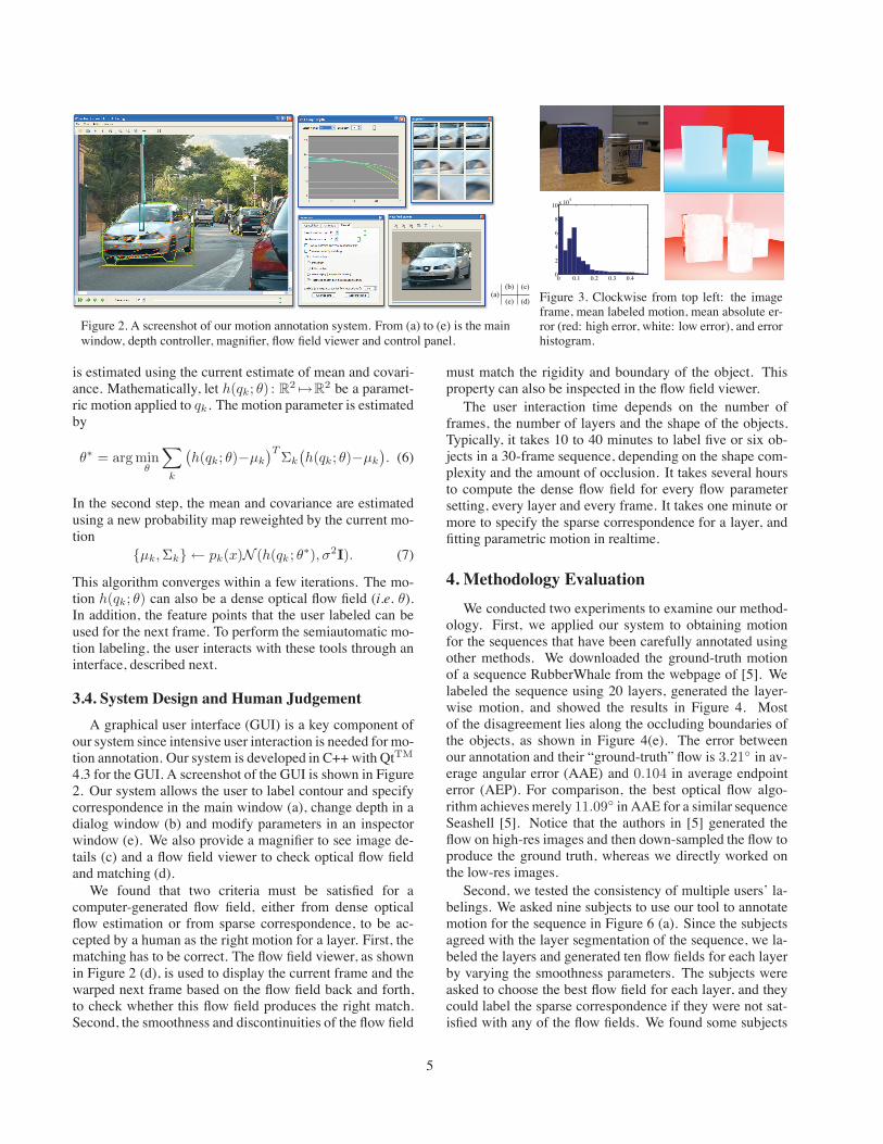
Figure 2. A screenshot of our motion annotation system. From (a) to (e) is the mainwindow, depth controller, magnifier, flow field viewer and control panel.
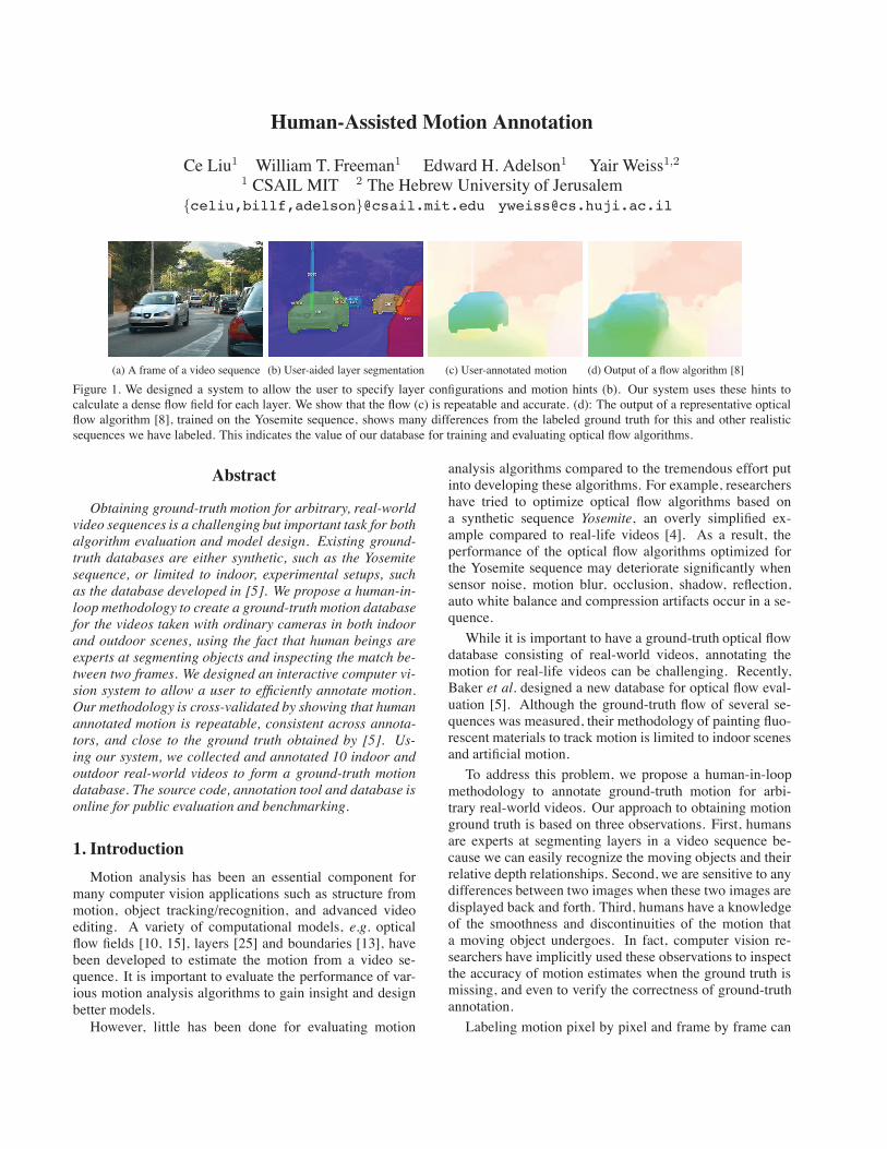
0 0.1 0.2 0.3 0.40
2
4
6
8
10x 104
Figure 3. Clockwise from top left: the imageframe, mean labeled motion, mean absolute er-ror (red: high error, white: low error), and errorhistogram.
is estimated using the current estimate of mean and covari-ance. Mathematically, let h(qk; θ) : R
2 �→R2 be a paramet-
ric motion applied to qk. The motion parameter is estimatedby
θ∗ = arg minθ
∑k
(h(qk; θ)−μk
)T Σk
(h(qk; θ)−μk
). (6)
In the second step, the mean and covariance are estimatedusing a new probability map reweighted by the current mo-tion
{μk, Σk} ← pk(x)N (h(qk ; θ∗), σ2I). (7)
This algorithm converges within a few iterations. The mo-tion h(qk; θ) can also be a dense optical flow field (i.e. θ).In addition, the feature points that the user labeled can beused for the next frame. To perform the semiautomatic mo-tion labeling, the user interacts with these tools through aninterface, described next.
3.4. System Design and Human Judgement
A graphical user interface (GUI) is a key component ofour system since intensive user interaction is needed for mo-tion annotation. Our system is developed in C++ with QtTM
4.3 for the GUI. A screenshot of the GUI is shown in Figure2. Our system allows the user to label contour and specifycorrespondence in the main window (a), change depth in adialog window (b) and modify parameters in an inspectorwindow (e). We also provide a magnifier to see image de-tails (c) and a flow field viewer to check optical flow fieldand matching (d).
We found that two criteria must be satisfied for acomputer-generated flow field, either from dense opticalflow estimation or from sparse correspondence, to be ac-cepted by a human as the right motion for a layer. First, thematching has to be correct. The flow field viewer, as shownin Figure 2 (d), is used to display the current frame and thewarped next frame based on the flow field back and forth,to check whether this flow field produces the right match.Second, the smoothness and discontinuities of the flow field
must match the rigidity and boundary of the object. Thisproperty can also be inspected in the flow field viewer.
The user interaction time depends on the number offrames, the number of layers and the shape of the objects.Typically, it takes 10 to 40 minutes to label five or six ob-jects in a 30-frame sequence, depending on the shape com-plexity and the amount of occlusion. It takes several hoursto compute the dense flow field for every flow parametersetting, every layer and every frame. It takes one minute ormore to specify the sparse correspondence for a layer, andfitting parametric motion in realtime.
4. Methodology Evaluation
We conducted two experiments to examine our method-ology. First, we applied our system to obtaining motionfor the sequences that have been carefully annotated usingother methods. We downloaded the ground-truth motionof a sequence RubberWhale from the webpage of [5]. Welabeled the sequence using 20 layers, generated the layer-wise motion, and showed the results in Figure 4. Mostof the disagreement lies along the occluding boundaries ofthe objects, as shown in Figure 4(e). The error betweenour annotation and their “ground-truth” flow is 3.21◦ in av-erage angular error (AAE) and 0.104 in average endpointerror (AEP). For comparison, the best optical flow algo-rithm achieves merely 11.09◦ in AAE for a similar sequenceSeashell [5]. Notice that the authors in [5] generated theflow on high-res images and then down-sampled the flow toproduce the ground truth, whereas we directly worked onthe low-res images.
Second, we tested the consistency of multiple users’ la-belings. We asked nine subjects to use our tool to annotatemotion for the sequence in Figure 6 (a). Since the subjectsagreed with the layer segmentation of the sequence, we la-beled the layers and generated ten flow fields for each layerby varying the smoothness parameters. The subjects wereasked to choose the best flow field for each layer, and theycould label the sparse correspondence if they were not sat-isfied with any of the flow fields. We found some subjects
5
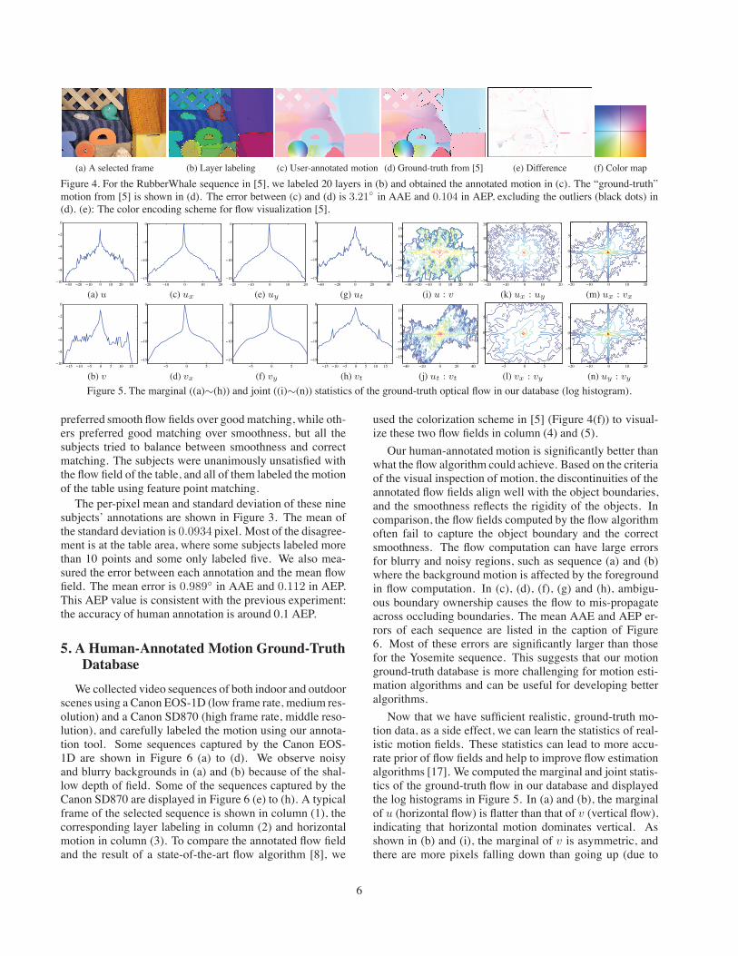
(a) A selected frame (b) Layer labeling (c) User-annotated motion (d) Ground-truth from [5] (e) Difference (f) Color map
Figure 4. For the RubberWhale sequence in [5], we labeled 20 layers in (b) and obtained the annotated motion in (c). The “ground-truth”motion from [5] is shown in (d). The error between (c) and (d) is 3.21◦ in AAE and 0.104 in AEP, excluding the outliers (black dots) in(d). (e): The color encoding scheme for flow visualization [5].
−30 −20 −10 0 10 20 30−10
−8
−6
−4
−2
0
−20 −10 0 10 20
−15
−10
−5
0
−20 −10 0 10 20
−15
−10
−5
0
−40 −20 0 20 40
−15
−10
−5
0
−30 −20 −10 0 10 20 30
−15
−10
−5
0
5
10
15
−20 −10 0 10 20−20
−10
0
10
20
−20 −10 0 10 20
−5
0
5
(a) u (c) ux (e) uy (g) ut (i) u : v (k) ux : uy (m) ux : vx
−15 −10 −5 0 5 10 15−10
−8
−6
−4
−2
0
−5 0 5
−15
−10
−5
0
−5 0 5
−15
−10
−5
0
−15 −10 −5 0 5 10 15
−15
−10
−5
0
−40 −20 0 20 40
−15
−10
−5
0
5
10
15
−5 0 5
−5
0
5
−20 −10 0 10 20
−5
0
5
(b) v (d) vx (f) vy (h) vt (j) ut : vt (l) vx : vy (n) uy : vy
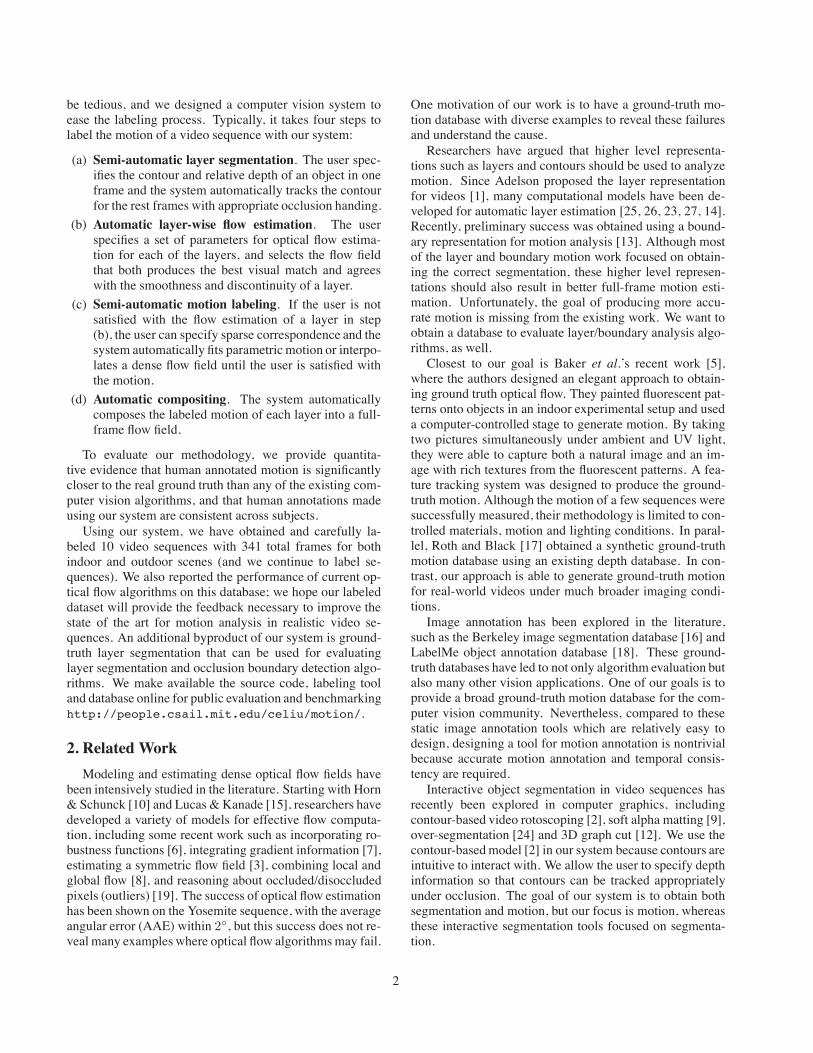
Figure 5. The marginal ((a)∼(h)) and joint ((i)∼(n)) statistics of the ground-truth optical flow in our database (log histogram).
preferred smooth flow fields over good matching, while oth-ers preferred good matching over smoothness, but all thesubjects tried to balance between smoothness and correctmatching. The subjects were unanimously unsatisfied withthe flow field of the table, and all of them labeled the motionof the table using feature point matching.
The per-pixel mean and standard deviation of these ninesubjects’ annotations are shown in Figure 3. The mean ofthe standard deviation is 0.0934 pixel. Most of the disagree-ment is at the table area, where some subjects labeled morethan 10 points and some only labeled five. We also mea-sured the error between each annotation and the mean flowfield. The mean error is 0.989◦ in AAE and 0.112 in AEP.This AEP value is consistent with the previous experiment:the accuracy of human annotation is around 0.1 AEP.
5. A Human-Annotated Motion Ground-TruthDatabase
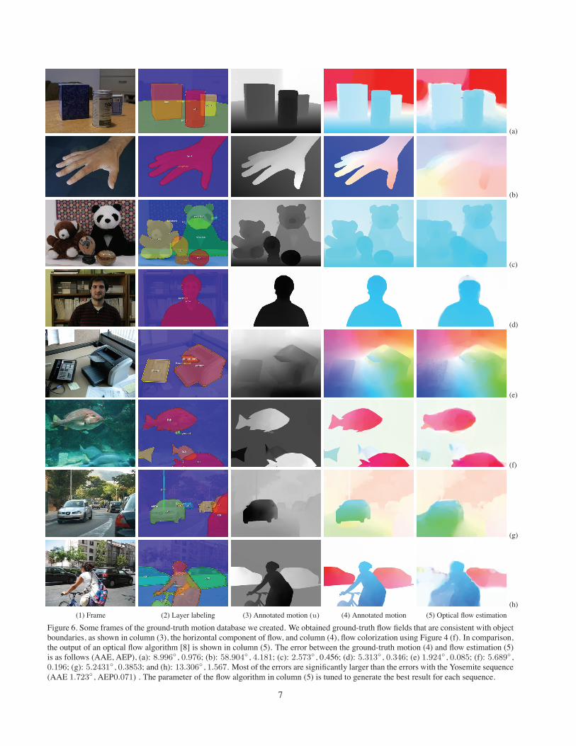
We collected video sequences of both indoor and outdoorscenes using a Canon EOS-1D (low frame rate, medium res-olution) and a Canon SD870 (high frame rate, middle reso-lution), and carefully labeled the motion using our annota-tion tool. Some sequences captured by the Canon EOS-1D are shown in Figure 6 (a) to (d). We observe noisyand blurry backgrounds in (a) and (b) because of the shal-low depth of field. Some of the sequences captured by theCanon SD870 are displayed in Figure 6 (e) to (h). A typicalframe of the selected sequence is shown in column (1), thecorresponding layer labeling in column (2) and horizontalmotion in column (3). To compare the annotated flow fieldand the result of a state-of-the-art flow algorithm [8], we
used the colorization scheme in [5] (Figure 4(f)) to visual-ize these two flow fields in column (4) and (5).
Our human-annotated motion is significantly better thanwhat the flow algorithm could achieve. Based on the criteriaof the visual inspection of motion, the discontinuities of theannotated flow fields align well with the object boundaries,and the smoothness reflects the rigidity of the objects. Incomparison, the flow fields computed by the flow algorithmoften fail to capture the object boundary and the correctsmoothness. The flow computation can have large errorsfor blurry and noisy regions, such as sequence (a) and (b)where the background motion is affected by the foregroundin flow computation. In (c), (d), (f), (g) and (h), ambigu-ous boundary ownership causes the flow to mis-propagateacross occluding boundaries. The mean AAE and AEP er-rors of each sequence are listed in the caption of Figure6. Most of these errors are significantly larger than thosefor the Yosemite sequence. This suggests that our motionground-truth database is more challenging for motion esti-mation algorithms and can be useful for developing betteralgorithms.
Now that we have sufficient realistic, ground-truth mo-tion data, as a side effect, we can learn the statistics of real-istic motion fields. These statistics can lead to more accu-rate prior of flow fields and help to improve flow estimationalgorithms [17]. We computed the marginal and joint statis-tics of the ground-truth flow in our database and displayedthe log histograms in Figure 5. In (a) and (b), the marginalof u (horizontal flow) is flatter than that of v (vertical flow),indicating that horizontal motion dominates vertical. Asshown in (b) and (i), the marginal of v is asymmetric, andthere are more pixels falling down than going up (due to
6
(a)
(b)
(c)
(d)
(e)
(f)
(g)
(h)
(1) Frame (2) Layer labeling (3) Annotated motion (u) (4) Annotated motion (5) Optical flow estimation
Figure 6. Some frames of the ground-truth motion database we created. We obtained ground-truth flow fields that are consistent with objectboundaries, as shown in column (3), the horizontal component of flow, and column (4), flow colorization using Figure 4 (f). In comparison,the output of an optical flow algorithm [8] is shown in column (5). The error between the ground-truth motion (4) and flow estimation (5)is as follows (AAE, AEP), (a): 8.996◦ , 0.976; (b): 58.904◦ , 4.181; (c): 2.573◦ , 0.456; (d): 5.313◦ , 0.346; (e) 1.924◦ , 0.085; (f): 5.689◦ ,0.196; (g): 5.2431◦ , 0.3853; and (h): 13.306◦ , 1.567. Most of the errors are significantly larger than the errors with the Yosemite sequence(AAE 1.723◦ , AEP0.071) . The parameter of the flow algorithm in column (5) is tuned to generate the best result for each sequence.
7
gravity). The marginals of the 1st-order derivatives of theflows are sparse, as shown in (c) to (f). Unlike the marginalsof synthetic flow fields [17], our statistics show that the ver-tical flow is sparser than the horizontal flow, consistent withthe fact that horizontal motion has a larger range. The tem-poral derivatives of the flow are not as sparse as the spa-tial ones, as depicted in (g) and (h). The joint histogramin (j) suggests that horizontal and vertical motion are likelyto increase or decrease together temporally. The joint his-tograms in (k) and (l) reveal that the discontinuities of theflow are isotropic. At motion discontinuities, the changeof vertical motion may dominate the change of horizontalmotion, and vice versa, as shown in (m) and (n).
6. Conclusion
Motion analysis algorithms have been in use for decades,but little has been done to obtain the ground-truth motionfor real-world videos. We presented a methodology andsystem to obtain ground-truth motion through humanannotation. Our system is built upon several state-of-the-artmotion analysis algorithms that allow the annotation ofevery pixel and every frame. A special graphical user in-terface is designed to allow the user to label layers, inspectmotions, select parameters, and specify sparse correspon-dences. Our methodology is validated by comparison withthe ground-truth motion obtained through other means andby measuring the consistency of human annotation. Usingour system, we collected a motion ground-truth databaseconsisting of challenging real-world videos for algorithmevaluation and benchmarking. We hope this database andour annotation code will lead to improved algorithms foroptical flow and layered motion analysis.
Acknowledgement
Funding for this research was provided by NGA NEGI-1582-04-0004, Shell Research, ONR-MURI grant N00014-06-1-0734 and a Xerox fellowship.
References
[1] E. H. Adelson. Layered representations for image coding.Vision and Modeling Technical Report 181, MIT Media Lab-oratory, 1991.
[2] A. Agarwala, A. Hertzmann, D. H. Salesin, and S. M.Seitz. Keyframe-based tracking for rotoscoping and anima-tion. ACM SIGGRAPH, 23(3):584–591, 2004.
[3] L. Alvarez, R. Deriche, T. Papadopoulo, and J. Sanchez.Symmetrical dense optical flow estimation with occlusionsdetection. In Proc. ECCV, pages 721–735, 2002.
[4] I. Austvoll. A Study of the Yosemite Sequence Used as aTest Sequence for Estimation of Optical Flow, pages 659–668. Lecture Notes in Computer Science. Springer Berlin /Heidelberg, 2005.
[5] S. Baker, D. Scharstein, J. Lewis, S. Roth, M. J. Black, andR. Szeliski. A database and evaluation methodology for op-tical flow. In Proc. ICCV, 2007.
[6] M. J. Black and P. Anandan. The robust estimation of mul-tiple motions: parametric and piecewise-smooth flow fields.Computer Vision and Image Understanding, 63(1):75–104,January 1996.
[7] T. Brox, A. Bruhn, N. Papenberg, and J. Weickert. High ac-curacy optical flow estimation based on a theory for warping.In Proc. ECCV, pages 25–36, 2004.
[8] A. Bruhn, J. Weickert, , and C. Schnorr. Lucas/Kanade meetsHorn/Schunk: combining local and global optical flow meth-ods. IJCV, 61(3):211–231, 2005.
[9] Y.-Y. Chuang, A. Agarwala, B. C. Y.-Y. Chuang, A. Agar-wala, B. Curless, D. H. Salesin, and R. Szeliski. Video mat-ting of complex scenes. In ACM SIGGRAPH, 2002.
[10] B. K. P. Horn and B. G. Schunck. Determing optical flow.Artificial Intelligence, 17:185–203, 1981.
[11] M. Isard and A. Blake. Condensation – conditional densitypropagation for visual tracking. IJCV, 29(1):5–28, 1998.
[12] Y. Li, J. Sun, and H.-Y. Shum. Video object cut and paste. InACM SIGGRAPH, 2005.
[13] C. Liu, W. T. Freeman, and E. H. Adelson. Analysis of con-tour motions. In NIPS, 2006.
[14] C. Liu, A. Torralba, W. T. Freeman, F. Durand, and E. H.Adelson. Motion magnification. In ACM SIGGRAPH, pages519–526, 2005.
[15] B. Lucas and T. Kanade. An iterative image registration tech-nique with an application to stereo vision. In Proc. of the Intl.Joint Conf. on Artificial Intelligence, pages 674–679, 1981.
[16] D. Martin, C. Fowlkes, D. Tal, and J. Malik. A databaseof human segmented natural images and its application toevaluating segmentation algorithms and measuring ecologi-cal statistics. In Proc. ICCV, pages 416–423, 2001.
[17] S. Roth and M. Black. On the spatial statistics of opticalflow. IJCV, 74(1):33–50, 2007.
[18] B. C. Russell, A. Torralba, K. P. Murphy, and W. T. Freeman.Labelme: a database and web-based tool for image annota-tion. IJCV, 2008.
[19] P. Sand and S. J. Teller. Particle video: long-range motionestimation using point trajectories. In Proc. CVPR, volume 2,pages 2195–2202, 2006.
[20] J. Shi and C. Tomasi. Good features to track. In Proc. CVPR,pages 593–600, 1994.
[21] R. Szeliski. Fast surface interpolation using hierarchical ba-sis functions. TPAMI, 12(6):513–528, 1990.
[22] R. Szeliski. Image alignment and stiching: A tutorial. Foun-dations and Trends in Computer Graphics and Computer Vi-sion, 2(1), 2006.
[23] P. H. S. Torr, R. Szeliski, and P. Anandan. An integratedBayesian approach to layer extraction from image sequences.TPAMI, 23(3):297–304, 2001.
[24] J. Wang, P. Bhat, A. Colburn, M. Agrawala, and M. Cohen.Interactive video cutout. In ACM SIGGRAPH, 2005.
[25] J. Y. A. Wang and E. H. Adelson. Representing moving im-ages with layers. IEEE Trans. Image Processing, 3(5):625–638, 1994.
[26] Y. Weiss and E. H. Adelson. Perceptually organized EM:A framework for motion segmentation that combines infor-mation about form and motion. Technical Report 315, MITMedia Lab Perceptual Computing Section, 1994.
[27] J. Wills, S. Agarwal, and S. Belongie. What went where. InProc. CVPR, pages 37–44, 2003.
8