Embed Size (px)
Citation preview


Matrix Technologies Corporation
22 Friars Drive
Hudson, NH 03051 USA
Phone: (800) 345-0206
www.matrixtechcorp.com
Rev. 1.6May 2006
®
& WellMate Stacker
User Manual

Trademarks and Copyright© 2005 Matrix Technologies Corp. All rights reserved.
No part of this publication may be reproduced, stored in a retrieval system, or transmitted, in any form or by any means, in whole or in part, without the prior written permission of Matrix Technologies Corporation.
WellMate is a trademark and Matrix Technologies Corp. and the Matrix logo are registered trademarks of Matrix Technologies Corp.
Third party products are registered trademarks of their respective companies in the United States and/or other countries.

Contents
®
III
Table of ContentsA. INTRODUCTION ...................................................... 1
B. INSTRUMENT OVERVIEW ...................................... 2 1. General Description .......................................................2 2. Keypad and LED Display ...............................................6 3. Stacker Unit ...................................................................8 4. Specifi cations.................................................................9 5. Hazards/Precautions ...................................................12
C. CONFIGURING THE DEVICE ................................ 13 1. Install the Tubing Cartridge ..........................................13 2. Attach the Removable Plate Carriage/Stage ...............16 3. Attach the Waste-Fluid Vessel .....................................17 4. Set Up Plates ...............................................................18 5. Install Stackers (optional) ............................................21 6. Attach the Power Cord.................................................23
D. SETTING UP AND RUNNING THE INSTRUMENT ........................................................ 24 1. Prime the Tubing Cartridge ..........................................24 2. Create, Load and Save a Program in Memory ............25 3. Run a Program From Memory .....................................27 4.Program Lock Freature Instructions ...............................29 5. Overwrite a Locked Program.........................................30 6. Set Up and Operate Stacker Base Unit .......................31 7. Operate the Instrument Manually ................................33 8. Adjust the X-Axis Stage Position .................................34 9. Adjust the Dispensing Speed.......................................36 10. Additional Functions ....................................................37
E. TUBING CARTRIDGE MAINTENANCE AND RECALIBRATION .......................................... 39 1. Clean the Tubing Assembly .........................................39 2. Recalibrate the Tubing Cartridge If Necessary ............40
F. HELPFUL HINTS .................................................... 43
G. TROUBLESHOOTING ........................................... 44

IV
Contents
H. APPENDICES ......................................................... 47 1. Plate Setup ....................................................................47 2. Chemical Compatibility ..................................................51 3. RS-232 ASCII Commands for Remote Device Activation ...........................................................................53 4. WellMate Schematic .....................................................64 5. Customer Service ..........................................................65
WARRANTY .................................................................. 66PACKING LIST .............................................................. 69LIST OF REPLACEMENT PARTS AND ACCESSORIES .................................................... 65
INDEX

1
®
A. IntroductionThe WellMate instrument from Matrix Technologies is a high-speed, small footprint, 8-channel fl uid dispenser for 6, 12, 24, 48, 96, and 384-well microplates. It repetitively dispenses samples and reagents into microplates, with high accuracy and effi ciency. An optional stacker unit provides higher throughput and walk-away capability.
You can program the WellMate unit with dispensing protocols, setting dispense volumes, plate type, and more.
Features and applications of the WellMate instrument include:
• Height-adjustable dispense head that accommodates shallow- and deep-well plates and blocks.
• High-resolution, stepper-motor technology that allows fast, accurate dispensing.
• Low-cost, replaceable tubing cartridges.
• Dynamic dispense volume range (1.0μl–2000μl), programmable in 1.0μl increments.
• Easy programming that allows you to select individual plate columns for dispensing.
• Memory-storage capacity for up to 18 fi les.
• Full RS-232 programming for ease of integration.
• Optional OCX driver interface for integration.
• Removable plate stage that allows easy cleaning of the PTFE coated base.
• Optional stacker unit to process 25 or 50 plates in a single run.

2
B. Instrument Overview1. General Description
The WellMate instrument dispenses samples and reagents effi ciently through use of a peristaltic pump mechanism and a unique, disposable tubing cartridge. Operators can adjust nozzle height to customize use of the instrument for different plate confi gurations (for example, fl at-bottom plates or V-bottom plates).
Your WellMate instrument package provides these items:
• Base unit.• AC power cord.• Two disposable 8-channel tube assemblies, with
silicone-based tubing and polypropylene nozzles. One each of:
• Standard-bore tubing cartridge, for use with 96-well (shallow or deep well) microplates. ο Nozzle orifi ce ID 0.023 in (0.58 mm). ο Dispenses volumes 20–2000μl. ο Applications include sterile plate fi lling and
dispensing of cellular materials, viscous fl uids, and beads.
ο To order replacement 5-pack, use item no. 201-30001.
• Small-bore tubing cartridge, for use with 96- and 384-well (shallow or deep well) microplates.
ο Nozzle orifi ce ID 0.015 in (0.38 mm). ο Dispenses volumes 1–200μl. ο Applications include sterile plate fi lling, dispensing of
high vapor pressure fl uids, and dispensing of small volumes (1–200μl) with enhanced precision.
ο To order replacement 5-pack,use item no. 201-30002.

3
®
• Nozzle-height reference scale.• Nozzle-height spacer guide.• 7/64-inch Allen wrench (for use in tubing-cartridge
adjustment).• 1/16-inch Allen wrench (for Y-axis arm).• Universal-microplate removable stage.• Waste-fl uid vessel with tubing.• Sample Microplate Starter Kit.• Manual.
You can also purchase the optional WellMate Stacker unit, which contains:
• Power Cord.• Connection Cable.• Priming trough with tubing and hardware.• Chimney support brackets and hardware.• Stacker base.• 2 breakaway washers.
You must provide the following:
• Container of liquid to be dispensed.• Liquid vessels (6, 12, 24, 48, 96, or 384-well
SBS-format microplates).• RS-232 Dsub connection cable if you wish to control
the instrument from a remote device (To order: Matrix item number 501-30019).
• Container to receive fl uid drained from waste-fl uid vessel.
Instrument Overview

4
Instrument Overview
The following fi gure shows the primary components of the WellMate instrument:
The WellMate base unit also comes with the following components:
Disposable Tubing Cartidges
Keypad
Removable Plate Carriage/Stage w/Spacer Guide
Waste-Fluid Vessel
Plate-type Selector
Nozzle Head
Power CordRemovable Plate Carriage/Stage
Waste-Fluid Vessel
Nozzle HeightSpacer Guide;Allen Wrench
NozzleHead
Removable Weight
8-Channel Disposable Tubing Cartridge

5
Instrument Overview
®
Note: Only one disposable tubing cartridge appears in the previous photograph; however, two disposable tubing cartridges are included in the initial system package: one standard-bore tubing and one small-bore tubing.
The WellMate Stacker package comes with the following components:
Power Cord
Priming Trough
Connection Cable
Chimney SupportBrackets and
Hardware

6
Instrument Overview
2. Keypad and LED Display
The keypad allows the operator to program and execute dispense operations. You can also execute “manual operations” (without using a preprogrammed dispense volume) by pressing and releasing the PRIME and EMPTY keys on the keypad.
Instructions for using the keypad are described under Setting up and Running the Instrument beginning on page 24.
Key and Display Description (clockwise from top left):
LED Display — Displays volume, selected channel, program number, and error-message codes.
SELECT — When PATTERN mode is selected, allows you to cycle through channels (individual tubes) to toggle them on or off for dispense. When MEMORY mode is selected, allows you to fi rst load and then save a program in memory.
PLATE Type LEDs — Indicates which plate type (96 or 384-well) is currently selected.
LED Display Select Plate Start, Stop
Mode
Reset Vol (µl)Pattern MemoryModes
Up, Down(+,-)
Alarm Prime, Empty(for manually fi lling
receptacles)
7
Instrument Overview
®
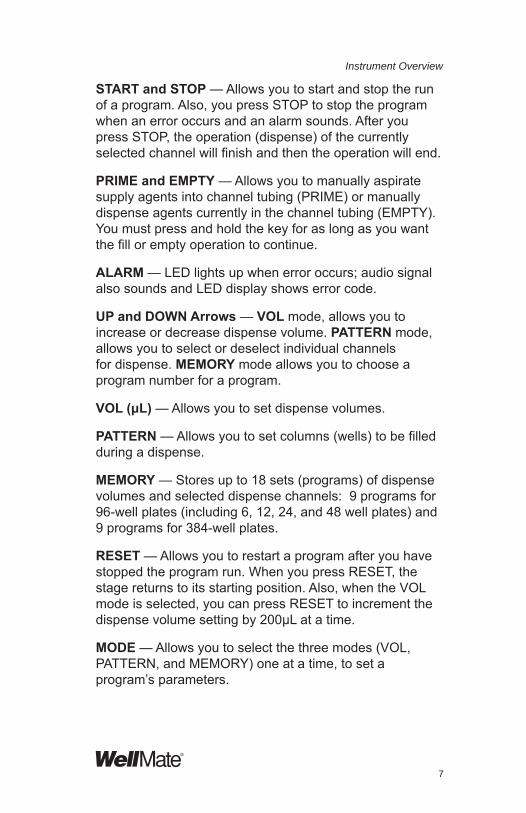
START and STOP — Allows you to start and stop the run of a program. Also, you press STOP to stop the program when an error occurs and an alarm sounds. After you press STOP, the operation (dispense) of the currently selected channel will fi nish and then the operation will end.
PRIME and EMPTY — Allows you to manually aspirate supply agents into channel tubing (PRIME) or manually dispense agents currently in the channel tubing (EMPTY). You must press and hold the key for as long as you want the fi ll or empty operation to continue.
ALARM — LED lights up when error occurs; audio signal also sounds and LED display shows error code.
UP and DOWN Arrows — VOL mode, allows you to increase or decrease dispense volume. PATTERN mode, allows you to select or deselect individual channels for dispense. MEMORY mode allows you to choose a program number for a program.
VOL (μL) — Allows you to set dispense volumes.
PATTERN — Allows you to set columns (wells) to be fi lled during a dispense.
MEMORY — Stores up to 18 sets (programs) of dispense volumes and selected dispense channels: 9 programs for 96-well plates (including 6, 12, 24, and 48 well plates) and 9 programs for 384-well plates.
RESET — Allows you to restart a program after you have stopped the program run. When you press RESET, the stage returns to its starting position. Also, when the VOL mode is selected, you can press RESET to increment the dispense volume setting by 200μL at a time.
MODE — Allows you to select the three modes (VOL, PATTERN, and MEMORY) one at a time, to set a program’s parameters.

8
Instrument Overview
3. Stacker Unit
Stacker base unit: Attaches to the standard WellMate unit to accommodate stacker chimneys. Used in conjunction with the WellMate instrument to automate the liquid dispensing and plate handling process.
Optical plate sensors: Allows the stacker unit to run until the stacker chimney is empty, then stops the run.
Stacker chimneys: Tall chimneys accommodate up to 50 standard height plates, short chimneys accommodate up to 25 standard height plates. Both will accommodate shallow plates, deep well plates, blocks or tube racks up to 3.5 in or 89 mm. Interchangeable with the PlateMate® Plus system.
Built in waste reservoir: Drains waste fl uid.

9
Instrument Overview
®
4. Specifi cations
Table 1. WellMate Specifi cations
Table 2. Standard-bore Tubing Cartridge Specifi cations (item no. 201-30001)
Power supply AC 100–240V, 50/60Hz 40VADimensions (HxWxd)
14.75* x 11.5 x 8.5 in (37.5 x 30 x 21.6 cm) (*Allow at least 3 more inches [7.62 cm] in width for extension of tubing and ~6 more inches [15.24 cm] in depth for extensions of power cord and waste-fl uid tubing.).
Weight 24 lbs (10.89 kg)
Description8-channel, pre-sterilized, standard-bore disposable tubing cartridge. Inner diameter nozzle orifi ce = 0.023 in (0.58 mm).
Recommended dispense volumes 20μl to 2000μl.
Recommended uses
With 6, 12, 24, 48, or 96-well (shallow- or deep-well) plates, for:
• Sterile plate fi lling
• Dispensing of volumes 20–2000µl
• Dispensing of cellular materials
• Dispensing of viscous fl uidsDispense accuracy/precision +/-2.0% or 1.0µl
Precision limit 1000 96-well microplates processed with 100µl dispense volume

10
Instrument Overview
Table 3. Small-bore Tubing Cartridge Specifi cations (item no. 201-30002)
Table 4. Stainless Steel PTFE-coated tip Tubing Cartridge Specifi cations (item no. 201-30003)
Description8-channel, pre-sterilized, small-bore disposable tubing cartridge. Inner diameter nozzle orifi ce = 0.015 in (0.38 mm)
Recommended dispensevolumes
1µl to 200µl
Recommended uses
With 96-well or 384-well (shallow- or deep-well) plates, for:
• Sterile plate fi lling
• Enhanced dispense precision
• Dispensing of high vapor pressure fl uidsDispense accuracy/precision +/- 2.0% or 0.25µl < 20µl
Precision limit 1000 96-well microplates processed with 100µl dispense volume
Description 8-channel, pre-sterilized, stainless steel PTFE-coated tip tubing cartridge
Recommended dispense volumes
2µl to 2000µl
Recommended uses
With 6,12,24,48, 96 or 384-well (shallow- or deep-well) plates, for:
• Sterile plate fi lling
• Dispensing of viscous fl uids
• Dispensing of volumes 2-2000μlDispense accuracy/precision
+/- 2.0% or 0.25µl2.0% or 0.25μl
Precision limit 1000 96-well microplates processed with 100μl dispense volume.

11
Instrument Overview
®
Table 5. WellMate Stacker Unit Specifi cations (item no. 201-20001)
*Allow at least 2 inches clearance if unit is placed in a containment hood.
Description
Stacker base unit with plate sensors and built-in waste reservoir; two chimney sizes available, 50 or 25 plates (501-30005 or 501-30006)
Power Supply Input Voltage 100V AC or 240V ACConsumption 50/60 Hz -40VA
Measurements
Width 31.06 in (78.89 cm) Depth 12.65 in (32.13 cm)Height with Tall Stackers = 40 in (101.6 cm)*Height with Short Stackers = 28 in (71.12 cm)*
Weight 60 lbs (27.22 kg)
Plate Type96 and 384-well plates; shallow and deep wellCapacity: 25 standard-height plates 50 standard-height plates

12
Instrument Overview
5. Hazards/Precautions
Note the following hazards and precautions for setup, operation, and maintenance of the WellMate instrument:
Operator protection
• Always unplug the unit from the power outlet before you perform any service or maintenance task that does not require power.
• Do not touch nozzles or the stage when the unit is operating.
Base-unit protection
• Use only dilute detergent cleaning solutions to clean the unit. Do not clean the keypad with bleach solutions or other solvents. To clean the unit, fi rst remove the tubing assembly from the instrument. Then use a bleach solution (2%) or an aqueous-based cleaner to clean surfaces. Rinse solution completely from surface.
• If liquid leaks out of the tubing onto the stage or onto any other part of the instrument, stop the operation immediately and then wipe off the liquid.
Tubing-cartridge protection
• Inspect the nozzles and nozzle tips regularly to ensure that the tips are not clogged and that there is no debris in the nozzles. Clean them regularly following the procedures described on page 39.
• Be careful not to bend the nozzles.

13
®
C. Confi guring the Device1. Install the Tubing Cartridge
To install a tubing cartridge:
1. When installing the tube set, make sure that the adjustment screws are accessible. To do this, have the screws on the top half when you lay out the tube set so the adjustment screws will be toward the middle of the pump when presented on the machine.
2. Push the blue PUSH button on the front of the tube holder to open the mechanism.
Jaw is Open

14
Confi guring the Device
3. When installing the tubing, place the left-hand tube holder onto the arm fi rst. Then place the other holder into position. Rotate the arm so the tubing is set into position.

15
Confi guring the Device
®
4. Push the cover on the pump mechanism to the closed position.
5. Insert the nozzle tip head as shown in the following:
Adjustment screws are towards middle
of pump

16
Confi guring the Device
2. Attach the Removable Plate Carriage/Stage
1. Tilt the plate carriage/stage so that its front edge is slightly higher than its back edge. Slide the notch in the plate carriage piece up under the spring-loaded plunger. Push the stage in gently and fi rmly until the two posts on either side of the back edge of the stage slide completely into the slots on the base unit. Move the stage manually to the end of its rightward movement.
2. If the stage is not level with the nozzle tips, fi rst try pushing the stage toward the back of the unit to ensure that it is pushed in completely. If it is still not level, slide the stage under the nozzle tips, and put a weight on the left (your left) side of the stage. Then use a fl athead screwdriver to adjust the left nylon screw in the middle back of the stage, tightening the screw to push the stage down. Do the same with the right side of the stage, adjusting the right hand nylon screw. Check visually to ensure that the distance between the stage top and the bottom of the front nozzle tip is equal to the distance between the stage top and the bottom of the back nozzle tip; that is, bottoms of nozzle tips and stage top are parallel from front to back.
Nylon stage-levelingscrew are here, along back
edge of stage
Spring-loaded plunger is here behind removable plate carriage/stage

17
Confi guring the Device
®
If you are using 384-well plates and the stage is not level with the nozzle tips, the nozzles might not be properly targeted with all the columns in the plate. Slide the stage left and right. Then use a fl athead screwdriver to adjust the nylon screws as described above.
3. Attach the Waste-Fluid Vessel
Align the two holes on the top edge of the waste-fl uid vessel over the posts extending upward from the fl ange on the left side of the plate carriage, and drop the waste-fl uid vessel over the posts. Place the open end of the tube into a receptacle that sits below the surface of the instrument base.
CAUTION: Ensure that the open end of the tubing remains above any liquid in the receptacle; if it is immersed, the vessel will not drain properly.
The fi rst of the following two photos shows the waste-fl uid vessel detached from the plate carriage. It is very easy to remove and replace the vessel. The second photo shows the waste-fl uid vessel in place next to the plate carriage.

18
Confi guring the Device
4. Set Up Plates
For each type of plate you plan to use, set up a sample plate as follows:
1. Set the plate type by moving the plate type slide in toward the machine for 384-well plates and out and away from the machine for 96-well plates.
Move plate type slide in for 384-well and out for 96-well
plates
Waste-fl uid vessle and tubing

19
Confi guring the Device
®
2. Move the nozzle head down until it is just above the openings of the fi rst column of wells in the plate.
3. Visually check to see that the nozzle tips are straight and centered over the wells. If the tips are not centered, adjust the front to back position by turning the knob on the Y-axis arm.
Note: Use the 1.5 mm Allen wrench that is provided to tighten the setscrew after Y-axis adjustment.
4. Raise the nozzle tips. Put the nozzle height spacer guide on top of the microplate and then push the lever on the nozzle tips arm down until the two black standoffs on the tip holder rest on top of the spacer guide. This sets an ideal nozzle height for dispensing.
Turn knob to adjust Y-axis arm
Setscrew

20
Confi guring the Device
5. Optional: Peel the covering off the adhesive tape on the back of the nozzle-height reference scale and attach it to the instrument, to the left of the plate-type lever. When you have set the tips for a particular plate to the height you want to dispense from, mark the reference scale for that plate and height.
Nozzle height reference scale

21
Confi guring the Device
®
5. Install Stacker Base Unit (optional)
Note: The WellMate unit requires EPROM chip version 3.11 or higher. Contact your Matrix representative to install the EPROM chip.
Use the following procedure to install the WellMate Stacker Base Unit.
1. Remove the plate stage and fl uid reservoir from the WellMate Dispenser.
2. Place the WellMate instrument onto the stacker base unit in the space provided. The four rubber feet on the bottom of the WellMate instrument should be placed in the 4 holes of the stacker platform. See the following fi gure.
Location for rubber feet of WellMate instrument

22
Confi guring the Device
3. Attach the Chimney support brackets to the base of the stacker unit in the space provided. Each bracket comes with 2 Allen hex key screws.
4. Once the screws are in place, but not completely tightened, put the stacker chimney in place. While it is in place, tighten the hex screws.
5. Attach the tubing to the fl uid reservoir.
6. Insert the fl uid reservoir and screw it in place.
Note: Be sure that the waste reservoir lies fl at on the bottom of the track. If it is not properly seated fl at, it will interfere with the plate stage movement.
Fluid Reservoir

23
Confi guring the Device
®
7. Connect the stacker base to the WellMate with the connection cable provided. The stacker unit will use the COM 1 port (see following fi gure) while the WellMate uses the COM 2 port.
6. Attach the Power CordPlug the power cord into the power-cord receptacle on the back of the WellMate unit.
The stacker is now installed. Go to page 31 to set up and operate the stacker.
Stacker Back Panel
WellMate/StackerCable at Com1
WellMate Back Panel
Stacker Cable at Com2
WellMate Power Cable

24
D. Setting up and Running the InstrumentTurn the instrument on by pressing the power switch on the back of the instrument to ON.
You will need to prime the tubing cartridge whenever you install a different cartridge on the instrument.
Note: The tubing cartridge is already calibrated when you receive it; you do not need to calibrate it.
You can then create, load and save programs and operate the instrument programmatically OR operate the instrument manually. You can also adjust tip-to-well alignment by adjusting the X-axis stage position and you can change the dispensing speed setting.
This section describes those priming, programming, operation and adjustment tasks.
1. Prime the Tubing Cartridge
Whenever you change the tubing cartridge, you will need to prime it. The fi rst time you use the instrument, you will need to prime the tubing set.
To prime the tubing cartridge:
1. Put the supply ends of the channel tubes in a receptacle containing dH2O or dispense medium.
2. Ensure that the waste-fl uid vessel is below the dispensing end of the channel tube and that the open end of the waste-fl uid tubing is in a receptacle, with the end of the tubing ABOVE any liquid in that receptacle.
3. Lower the nozzle tips so that they are at the correct dispensing height above the waste-fl uid vessel or a plate on the stage.

25
®
Setting up and running the Instrument
4. Press and hold the PRIME key until a continuous fl ow moves through all the channel tubes. See page 38 for instructions on programming a timed prime.
Note: Prime new tube sets for 1 to 2 minutes with water before using them for dispensing. This initial priming helps to break in the new tube set and stretch out the tubes where they contact the roller head.
2. Create, Load, and Save a Program in Memory
You can construct and save up to 18 programs (9 for 6- to 96-well plates and 9 for 384-well plates) that allow you to easily adjust dispense volume and column use.
To program a dispense sequence to fi ll a plate, you will:
• Select a plate type (96 or 384).
• Set the dispense volume.
• Select columns (wells) to be fi lled in the dispense operation.
• Load the program into memory and save it.
1. Select the plate type:
Set the plate type by moving the plate type slide to accommodate the plate you will be using.
Move Plate Type Slide in for 384 and out for
96-well

26
Setting up and running the Instrument
Verify that the plate type LED for your plate lights up on the keypad. For 6, 12, 24, 48 or 96-well plates, make sure the 96 LED is illuminated; for 384-well plates, make sure the 384 LED is illuminated.
2. Set the dispense volume:
a. Press MODE. The VOL (μl) LED lights up.
b. Press the UP and DOWN arrows to increase or decrease volume (the current volume appears in the LED display).
Note: To increase the dispense volume in increments of 200µl, press RESET.
3. Select the dispense pattern (which plate columns are to be fi lled):
a. Press MODE. The PATTERN LED lights up. The two leftmost digits in the display show the column (for example, 01 for column 1). The third display digit, on the right of the display, is 0 or 1. A “0” indicates that this column is not selected to dispense; a “1” indicates that this column is selected to dispense.
Plate type LEDs

27
Setting up and running the Instrument
®
b. To change the current selection of the column used from on to off or off to on, press SELECT. The digit will be toggled to the other value, either “0” or “1”.
c. Press the up or down arrow to move to another column.
d. Continue to press SELECT to toggle dispense on or off for each column.
4. Save the program:
a. Press MODE. The MEMORY LED lights up.
b. Press the up or down arrow to move to the program number you want to save this program to. If you are using a 96-well plate, program numbers 1–9 appear, one at a time, in the display. If you are using a 384-well plate, numbers 11–19 appear in the display.
When the program number you want to use appears in the display, press SELECT. “LoAd” appears in the display. Press SELECT again. “SAVE” appears in the display.
c. Press START. PASS appears on the display.
d. Press MODE. The programmed dispense volume will appear on the display.
e. Press START to run the program.
3. Run a Program From Memory
1. Ensure that the supply ends of the channel tubes are in the container with the agent to be dispensed.
2. Ensure that the waste-fl uid vessel is in place and that the waste-fl uid tube is placed in a waste liquid container, with the open tube end ABOVE any waste liquid in the container.

28
Setting up and running the Instrument
3. Place the plate in the plate carriage.
4. Verify that the READY light and the correct LED for your plate type are lit on the keypad.
5. Test that the nozzle-tips height is correct by using the nozzle-height guide.
6. Press the MODE key twice; the MEMORY LED is lit. Then select the program you want to run.
7. Press SELECT. LoAd appears in the LED display.
8. Press START. The program dispense volume appears in the LED display.
9. Press START. The program begins running.
10. Press STOP if you need to stop the program. Press START if you want to restart from the point where the program stopped; press RESET to restart the program from the beginning.
11. When you are fi nished with the dispensing operations, return the agent remaining in the tubes to the supply receptacle or other container. Then rinse the tubing fi rst with water and then with alcohol to dry the tubing, or perform the appropriate cleaning action (see the maintenance information in the next section).
12. When you have fi nished using the instrument, leave the tubing in a resting position: unfold the left-hand side of the tubing assembly.

29
Setting up and running the Instrument
®
3. Program Lock Feature Instructions
1. Follow the steps above for creating the program.
2. Save and lock the program.
a. Press MODE. The memory LED lights up.
b. Press the up or down arrow to move to the program number you want to save the program to. If the 96 LED is illuminated, program numbers 1-9 appear, one at a time in the display. If the 384 LED is illuminated, numbers 11-19 appear in the display.
c. When the program number you want to use appears in the display, press SELECT. “LoAd” appears on the display.
d. Press SELECT again. “save” appears on the display.
e. Press START. PASS will appear on the display.
f. Press the PRIME button. “----“ will appear on the display. Press the UP or DOWN arrow to input the 4-digit password. (“0000” is not accepted) press the PRIME button to select the number for each digit.
g. Once the 4-digit password is set, press START to lock the program with the password. The program is now locked.
3. To run a locked program:
a. Select program number.
1. Press MODE until the memory LED is illuminated.
2. Use the UP or DOWN arrows to select the desired program number.

30
Setting up and running the Instrument
3. Press SELECT. “LoAd” appears on the display.
b. Press START. The volume set for that program will appear on the display.
c. Press START again, this will run the selected program.
5. Overwrite a Locked Program
1. Press MODE until the memory LED is illuminated.
2. Select the desired program number using the UP and DOWN arrows.
a. Press SELECT “LoAd” appears on the display.
b. Press SELECT again, PASS appears on the display if the program is locked.
c. Press PRIME button. “----“ appears on the display.
d. Use the UP or DOWN arrows to input the 4-digit password for that program. Pressing PRIME to select the number for each digit.
e. Once the password is on the display, press START to unlock the program.
f. If the password is correct, SAVE appears on the display.
g. Press MODE to select the volume and pattern to overwrite the program.
h. If the password for that program is incorrect, then the display does not change. Go through the steps again to re-enter the correct password.
i. Repeat steps to lock the program.

31
®
6. Set Up and Operate Stacker Base Unit
1. Turn the WellMate unit and the WellMate stacker base unit on.
2. Align the 96-well plate.
a. Turn the WellMate off and place a 96-well plate onto the plate shuttle. Keep the WellMate stacker powered on throughout this procedure.
b. Pull out the nozzle bar to the 96 plate position.
c. Press the Start and Stop keys simultaneously and turn on the WellMate. “POS” will show on the WellMate display.
d. Press the Start key. “96” should show on WellMate display. Verify that the “96” plate type light is illuminated.
e. Press the Start key. The plate shuttle should move until column 7 of the plate is under the dispense nozzle.
f. Check alignment of the nozzle over the wells.
If the horizontal alignment is off, press the up or down key to adjust the X-axis stage position under the nozzles.
If the vertical alignment is off, align the Y-axis stage position by turning the 2.5 mm Allen wrench clockwise (moves the entire WellMate unit backward) or counter-clockwise (moves the entire WellMate unit forward). See the following fi gure.
Setting up and running the Instrument

32
Setting up and running the Instrument
Note: In addition to the Y-axis stage adjustment, you can also use the Y-axis adjustment knob (see page 18 for Y-axis arm adjustment).
g. When you have fi nished aligning the 96-well plate under the nozzles, press the Reset button. The stage shuttle will move to its home position under the right stacker.
3. Align the 384-well plate.
a. Replace the 96-well plate with a 384-well plate. Push in the dispense nozzle arm and verify that the “384” indicator light on the WellMate is illuminated.
b. Press the START button. The plate shuttle should move until column 13, row set 1 of the plate is under the dispense nozzle.
c. Press the UP or DOWN key to adjust the stage position under the nozzles.
d. Align the Y-axis stage position with an Allen wrench.
e. When you have fi nished aligning the 384-well plate row set 1 under the nozzles, press the RESET button. The plate shuttle should move until column 13, row set 2 of the plate is under the dispense nozzle.
f. Press the UP or DOWN key to adjust the stage position under the nozzles.
Y-Axis Stage

33
Setting up and running the Instrument
®
g. When you have fi nished aligning the 384-well plate under the nozzles, press the RESET button. The stage shuttle will move to its home position under the right stacker.
4. Turn the WellMate unit off, then turn it on.
The WellMate stacker is ready for use. When you press START during manual operation, the fi rst plate in the stacker will be moved to the dispense position.
7. Operate the Instrument Manually
To operate the instrument manually:
1. Select the plate type.
Set the plate type by moving the plate type slide in toward the machine for 384-well plates and out away from the machine for 96-well plates.
Verify that the plate type LED for your plate (96 or 384) lights up on the keypad.
2. Put a plate or other receptacle on the stage.
3. Adjust the nozzle height to the correct height by using the nozzle height spacer guide.
4. Set the dispense volume:
a. Press MODE. The VOL (μL) LED lights up.
b. Press the UP and DOWN arrows to increase or decrease volume (the current volume appears in the LED Display).
Note: To increase the dispense volume in increments of 200µl, press RESET.
5. Select the dispense pattern (which plate columns are to be fi lled):

34
Setting up and running the Instrument
a. Press MODE. The PATTERN LED lights up. The two left-most digits in the display show the column (for example, 01 for column 1). The third display digit, on the right of the display, is 0 or 1. A “0” indicates that this column is not selected for dispense; a “1” indicates that this column is selected for dispense.
If you wish to change the current selection of the column use from on to off or off to on, press SELECT. The digit will be toggled to the other value, either 0 or 1.
b. Press the UP or DOWN arrow to move to another column.
c. Continue to press SELECT to toggle dispense on or off for each column.
6. Press the PRIME key to draw the agent into the tubes and ensure that liquid fl ows freely through all tubing in a continuous fl ow.
7. When you are fi nished with the dispensing operations, press the EMPTY key to return the agent remaining in the tubes to the supply receptacle or other container. Then rinse the tubing fi rst with water and then with alcohol to dry the tubing, or perform the appropriate cleaning action (see the maintenance information in the next section).
8. When you have fi nished using the instrument, leave the tubing in a resting position: unfold the left-hand side of the tubing assembly.
8. Adjust the X-Axis Stage Position for WellMate Unit
This feature allows the operator to “teach” the stage position for dispensing. Use this feature to fi ne-tune the desired plate position for dispensing to occur.

35
Setting up and running the Instrument
®
Note: Liquids tend to adhere to the walls of small tubing (such as tube sets for 384-well plate), especially when dispensing smaller volumes (9µl or less). To minimize the amount of liquid retained in the tubing, make sure that the Y-axis arm positions the tips directly over the middle of the wells (see page 18 for Y-axis arm adjustment) and the height gauge is used to set the nozzle over the plate.
1. Put a 96-well plate on the stage. Select plate type 96 (on the nozzle holder) and then turn off the instrument.
2. Press the START and STOP keys simultaneously and turn on the instrument.
3. Press START. Verify that the plate type LED on the display and the plate selector are both set to plate type 96.
4. Press START. The stage will move automatically so that column 7 is under the nozzle tips.
5. Press the UP and DOWN arrow keys to adjust the stage position until the tips are aligned in the wells as you want them to be. (The LED display will show a volume range from -300 to +300).
6. Press RESET, select plate type 384 (on the nozzle holder) and verify that the 384 LED is illuminated.
7. Replace the 96-well plates with a 384-well plate and press START. The 384-well plate will move to column 13.
8. Press the UP and DOWN arrow keys to adjust the stage position until the tips are aligned with the wells.
9. Press RESET when you have fi nished the adjustment and then turn off the instrument.

36
Setting up and running the Instrument
9. Adjust the Dispensing Speed
Please note, the tubing cartridge specifi cations are set using the highest speed (S-1)
1. Press the PRIME and EMPTY keys simultaneously and turn on the instrument.
2. Press SELECT to cycle through the three pump-speed choices as they appear in the LED Display. The choices are:
S-1 = High speed (This is the normal setting).
S-2 = Medium speed
S-3 = Low speed
3. When the speed you want to use shows in the display, turn off the instrument, and on again.

37
Setting up and running the Instrument
®
10. Additional Functions
The following functions are accessible through a special program mode (available with WellMate EPROM version 3.5 or higher):
• Pump Pause (PP): to initiate a pause after the dispense in-between each column.
• Pump Count (PC): to check or clear the pump count feature.
• Timed Prime (PT): to set the duration of time the pump motor runs when the prime button is pressed.
• Back Step (BS): to initiate a back step of the pump motor after the dispense and before the Pump Pause.
Note: This feature is useful when dispensing fl uids that may form droplets at the end of the tip nozzles, or when dispensing viscous fl uids.
To use this program mode:
1. While holding down the MODE button, press the SELECT button.
2. Press the SELECT button again to select the mode you want to program (PP, PC, PT, BS). Use the arrow buttons to set the parameters for the selected function. After you have set the program, press the SELECT button to save the setting.
Note: If you press MODE while in the function, you will exit without saving the setting and return to the previous display.
Pump Pause (PP): The pause duration is set in milli-second intervals. For example, 0.01-99.99 seconds are available for pausing the pump between dispense columns.
38
Setting up and running the Instrument
a. Use the UP or DOWN arrows to select the duration of the pause. The default pause duration is set to .01 milliseconds.
b. Press the SELECT button to save your setting.
Pump Count (PC): The number on the display represents how many revolutions the pump has made.
a. Press the SELECT button to clear the pump count.
b. Press the SELECT button again, when “sure” is displayed.
Note: If the count exceeds 9999, the count is displayed in exponential form, such as “10E3” for 10,000 revolutions or “12E4” for 123,456 revolutions.
Timed Prime (PT): The prime duration is set in real time seconds from 1-9999.
a. Select the time (for example, 20 for 20 seconds) using the UP or DOWN arrows
b. Press the SELECT button to save the time.
When the prime button is pressed under normal operation (and the timed prime is not zero), the system will count down the time for priming (for example, 20 seconds) rather than requiring you to hold down the prime button.
Back Step (BS): The back step volume is set in 100 nanosecond units. For example, 0.1 – 20.0µl are available for back stepping the pump motor after dispense and before pausing the pump.
a. Use the UP or DOWN arrows to select the duration of the back step. The default back step is set to 0.0µl.
b. Press the Select button to save your setting.

39
®
E. Tubing Cartridge Maintenance and RecalibrationThis section describes how to care for the tubing cartridge and then also how to recalibrate the cartridge if you wish to do so.
Note: Recalibration is generally not necessary. The tubing cartridges that come with your system have already been calibrated. That calibration will generally last until the precision limit for the tubing cartridge (1000 dispenses of 100µl each into a 96-well plate) has been reached. In most cases, particularly if all of the channels in the cartridge are no longer meeting precision specifi cations, you will simply want to replace the disposable cartridge with a new cartridge.
To optimize performance and extend the life of your tubing assembly, refer to the Helpful Hints section on page 43.
1. Clean the Tubing Assembly
Table 6. Care and Maintenance of Tubing Assembly
Task How Often? ProcedureRinse tubing After each
sample.Use dH2O to rinse the tubing assembly each time you change samples. Then rinse the tubing with alcohol to remove water.
Wash tubing At end of day’s use or between solutions.
Use a mild detergent solution or 10% bleach solution to clean the tubing. Then rinse it with fresh water and fi nally with alcohol.
Autoclave tubing if desired
As needed. No more than 3x
At 120º C for 20 minutes
Replace tubing As needed. Obtain a new tube assembly cartridge and install as you did the earlier set.
Clean nozzle tips As needed. Inspect the nozzle tips for signs of clogging or debris. Clean them with water and then rinse them with alcohol.
Tubing Cartridge Maintenance and Recalibration

40
Tubing Cartridge Maintenance and Recalibration
2. Recalibrate the Tubing Cartridge If Necessary
Note: The tubing cartridges to be recalibrated must be allowed to equilibrate to lab-room conditions for at least 2 hours prior to calibration.
Use a gravimetric test or optical scanning with a plate reader to determine whether a particular channel needs to be recalibrated.
1. Turn on the WellMate unit and set the volume to 50µl.
2. Verify that the dispense mode is set for (ten) columns of dispense, with 1-10 ON and with 11-12 OFF.
3. Weigh a tube and tare out the scale. Use this tube to collect the dispensed volume of each channel during the calibration sequence. Zero the scale between readings.
Note: There is a purge before each dispense cycle of the WellMate. It is important NOT to collect this drop in the tube as you perform the following operation. Allow the drop to fall prior to putting the tube under the nozzle.
4. Remove all tubes from the supply water, except channel 1, and make sure that this channel is still primed. Hold a tube under the channel 1 nozzle. Press the START key. Proceed to collect each of the (10) dispensed shots in the tube.
5. Weigh the water in the tube. The target weight of the liquid is 498 mg–502 mg. If the weight is not within these limits, use the 7/64-inch Allen wrench to turn the adjustment screw for the channel tube (on the supply side of the tubing).

41
Tubing Cartridge Maintenance and Recalibration
®
A clockwise turn will DECREASE the volume dispensed.
A counter-clockwise turn will INCREASE the volume dispensed.
Each FULL Revolution of the screw will adjust the volume level by approximately 8 mg for the ten shots dispensed (or 0.8 mg/dispense).
6. Repeat the previous step until three consecutive weights are within the gravimetric range stated above. Do this with all eight channels. Record results.
7. Fill the supply container with the appropriate medium for your plate reader.
8. Make sure that the plate carriage is properly in position on the unit. Insert a plate in the carriage and position the nozzle tips to correctly dispenseinto the plate.

42
Tubing Cartridge Maintenance and Recalibration
9. Select a program to fi ll the whole plate to the appropriate volume and press the START key to begin the dispense.
10. After the dispense operation has fi nished, insert the fi lled plate into the plate reader for evaluation.
11. After the plate has been read, evaluate the results. If any CVs for ANY row are greater than the specifi cations for the tube set, the tube set will need to be adjusted for that channel. Adjust the calibration by turning the adjustment screws as described earlier.
12. After all calibration is completed, rinse the tubing by putting the tube ends in a container holding distilled water and press and hold the PRIME key until enough liquid has passed through the tubing to clear it.
13. Repeat the rinse cycle using alcohol to remove all water from the line.

43
®
F. Helpful Hints• Liquid tends to adhere to the walls of small tubing (such as tube
sets for 384-well plate), especially when dispensing smaller volumes (9 uL or less). To minimize the amount of liquid retained in the tubing, make sure that the Y-axis arm positions the tips directly over the middle of the wells and the height gauge is used to set the nozzle over the plate. See Y-axis arm adjustment on page 18.
• When using a new tube set, prime the tubing for 5-10 minutes with water before using the set for testing. This initial priming helps to break in the new tube set and stretch out the tubes where they contact the roller head.
• Prolonged use of a tube set, especially if it is used constantly and not allows to “rest,” can cause results to vary over time. Possible reasons include: accumulation of bubbles in the tubing because the tubes were not fully purged; general wear over time.
• Continuous use of a tube set may also cause droplets to form outside the tips. You can reduce this problem by periodically checking the tips and gently removing any droplets with a sterile cloth. The greater the dispense volume or more frequent the dispenses, the more often the tips should be checked.
• Tube sets containing liquid and left idle for a long time can collect bubbles in the tubing. Purge the tube set, run air through the tubes, then prime with liquid.
• Tube sets that are not used for an extended period of time should be released from the roller head. Open the clamp lever to the rest position or take the tubing cartridge off the roller head completely.
• Persistent droplets that form outside one or more tips during dispenses may be caused by tip fl ash (fl aw in the tip). This problem can cause inaccurate results. The tube set should be replaced.
• For optimal dispense precision (especially with 384 well plates), set the nozzle height over the plate to 2.0 mm or less.

44
G. Troubleshooting Note: If you do not fi nd the answer to your question in the following table, contact your equipment provider. See page 65 for details on contact information.
Table 7. WellMate Troubleshooting: Issues and Solutions
Error Issue SolutionE001 Stage doesn’t move OR
doesn’t home.Press STOP to cancel the alarm.Press RESET to return to operation status.
E002 (384-well plates) Stage doesn’t return after reaching end position OR limit sensor remains on after stage returns to start position.
Press STOP to cancel the alarm.Press RESET to return to operation status.
E003 Plate type changes during dispense operation.
Plate selector arm was likely bumped into the wrong position.
Press STOP to cancel the alarm. Check the plate type setting and reset it if necessary.
Press RESET to return to operation status.
E004 Stage does not move to underneath the Pump while pump mechanism was activating. Error also occurs if home sensor or stage motor is not working.
Fix the stage to move underneath the pump while operating
OR adjust the home sensor
E006 Cover on pump mechanism was opened while adjusting x-axis stage position.
Do not open the pump cover while adjusting x-axis stage position.
E099 At fi rst, “o” (open) command was not transmitted.
There is no effective command e.g.”K” The wrong format for command.
The data of command is out of limit.
Check the connecting cable between the units and PC.
Use the correct command.
Use the correct format for command.
Troubleshooting

45
Troubleshooting
®
C001 PRIME or EMPTY key has been pressed while stage is not at home position.
Press STOP to cancel the alarm.
Press RESET to return the stage to home position.
Press PRIME or EMPTY to continue the operation.
E005 Jaw opened during operation.
Tubing safety bar is open. Raise it until it is in the closed position.
Liquid is dispensing on crosshairs between wells.
Check to see whether stage top is parallel to nozzle tips. If not, ensure that plate carriage is properly engaged on the two pins at the back of the unit.
Use a fl athead screwdriver to adjust the nylon screws to level the carriage.
Also, the mechanism on the bottom of the stage might not be activating, meaning the device is in an incorrect plate mode. Press the stage toward the back of the instrument.
Verify needles are at correct height by using nozzle-height spacer guide.
Ensure that nozzles are clean.
See section D number 5, adjusting the X-axis position.
Plugged nozzle Remove nozzle head from arm holder, place into container of water or alcohol with supply end of tubing. Using the PRIME and EMPTY keys, fl ush water or alcohol back and forth through tubing to remove debris.

46
Troubleshooting
Table 8. Stacker Troubleshooting: Issues and Solutions
Error Issue SolutionE101 Plate stage on the
WellMate is not at home position.
Turn off WellMate and Stacker unit. Make sure the plate stage on the WellMate is all the way to the right in its home position.
E103 Sensor is reporting that the right plate stage is not at the starting lift position.
Make sure that the right plate stage is in the correct position. Turn the stacker unit off, move the plate shuttle to access the right plate stage, and make sure the breakaway washer and screw are set correctly.
E104 Sensor is reporting that the left plate stage is not at the starting lift position.
Make sure that the left plate stage is in the correct position. Turn the stacker unit off, move the plate shuttle to access the left plate stage, and make sure the breakaway washer and screw are set correctly.
E105 A plate is on the right stage while the stage is lifting up.
Remove the plate from the right stage.
E106 A plate is on the left stage while the stage is lifting up.
Remove the plate from the left stage.

47
®
H. Appendices1. Plate Setup
The following graphics and tables illustrate the plate setup for 6, 12, 24, and 48 well plates.
6-Well Plate Setup
Troubleshooting

48
Appendices
12-Well Plate Setup

49
Appendices
®
24-Well Plate Setup

50
Appendices
48-Well Plate Setup
51
Appendices
®
2. Chemical Compatibility
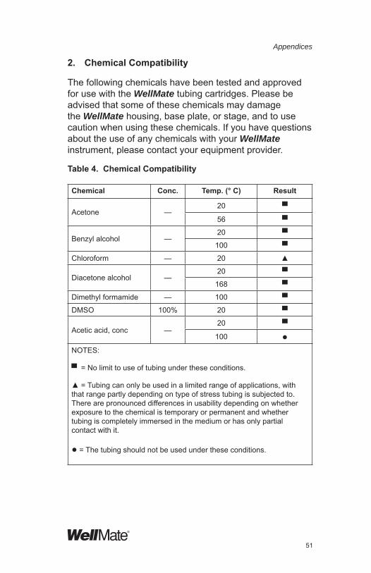
The following chemicals have been tested and approved for use with the WellMate tubing cartridges. Please be advised that some of these chemicals may damage the WellMate housing, base plate, or stage, and to use caution when using these chemicals. If you have questions about the use of any chemicals with your WellMate instrument, please contact your equipment provider.
Table 4. Chemical Compatibility
Chemical Conc. Temp. (° C) Result
Acetone —20 ▀
56 ▀
Benzyl alcohol —20 ▀
100 ▀
Chloroform — 20 ▲
Diacetone alcohol —20 ▀
168 ▀
Dimethyl formamide — 100 ▀
DMSO 100% 20 ▀
Acetic acid, conc —20 ▀
100 ●NOTES:
▀ = No limit to use of tubing under these conditions.
▲ = Tubing can only be used in a limited range of applications, with that range partly depending on type of stress tubing is subjected to. There are pronounced differences in usability depending on whether exposure to the chemical is temporary or permanent and whether tubing is completely immersed in the medium or has only partial contact with it.
● = The tubing should not be used under these conditions.

52
Appendices
Chemical Conc. Temp. (° C) ResultAcetic anhydride — 20 ▀
Ethanol —20 ▀
78 ▲
Hydrofl uoric acid 5% 20 ●
Glycol — 20 ▀
Glycerol — 100 ▀
Hexane — 20 ▲
Saline solution 10% 20 ▀
Methanol — 65 ▀ (1)
▲(1)
Sodium chlorate 20% 20 ▀
Phosphoric acid30%
20 ▀50%
Hydrochloric acid 10%20 ▀
80 ●
Sulfuric acid 10% 20 ▀
Detergent solution 1% 20 ▀
Hydrogen peroxide10%
20 ▀30%
NOTES:
▀ = No limit on use.
▲ = Caution: not appropriate for some uses.
● = Do not use.
(1) Two grades of ELASTOCIL® tubing were tested with each chemical; those 2 grades are: R401/60 standard mix and R800/80 highly fi lled mix. Compatibility of the 2 grades with each of the chemicals listed is the same EXCEPT for compatibility with methanol; for standard, compatibility is ▀; for highly fi lled, compatibility is ▲.

53
Appendices
®
3. RS-232 ASCII Commands for Remote Device Activation
To send commands to the WellMate instrument from a remote device, provide a Dsub-connector RS-232 cable (to order from Matrix: use item number 501-30019) and a Windows computer. Connect the cable from the COM 1 port on the back of the WellMate instrument to your computer.
This section lists
• Serial port communication specifi cations
• RS-232 commands
• Communication error messages
• Sample RS-232 commands

54
Appendices
Serial Port Communication Specifi cations
1. 9600 bps. STOP 1, PARITY-EVEN, X NONE, BITS-7, ALL ASCII
2. Serial Cable Confi guration
3. Essential Message Format
Any message not included in SXT and EXT should be ignored as noise.
4. Transmission Protocol
c. Transmission error with repeated “no response” is to be judged by the transmitting side.
d. PC does not return “ACK” against “R” transmission from WellMate.
G G
TXD TXD
RXD RXD
DTR DTR
DSR DSR
CTS CTS
RTS RTS
SXT ######## EXT
SXT (02H): Start of message
EXT (03H): End of message
a. Transmit Correct receive
ACK
b. Transmit Incorrect receive
No response
2 seconds delay
Re-transmit Correct receive
ACK

55
Appendices
®
5. Common Message
a. Positive Response STX ACK ETX
ACK (06H)
Table 9 lists the ASCII commands you can send from the PC to the WellMate instrument.
Table 10 lists communication error messages.
Some sample commands follow Table.
Table 9. RS-232 Commands
Syntax DATA Function CommentA Restart after the
pause and the error.
Resumes from the point where pause or error occurred.
ACK Positive response
BSR Reads the Back Step Volume
Returns a four character string 0000 through 9999. Volume is in 100 nanoliter units.
BSW xxxx Sets the Back Step Volume.
Must be a four character string 0000 through 9999. Volume is in 100 nanoliter units.
C COM CLOSE Terminates RS-232 commands.
FC Fill a plate. Equivalent to pushing the start button
FP ppb Fills a plate using the program pp stored in memory
If b is ‘1’ the program pp is copied to program 00 for pp < 10 and to program 10 for pp > 10
For 96 well plates pp must be 00
For 384 well plates pp must be 10 through 19

56
Appendices
Syntax DATA Function CommentO COM OPEN Open is not allowed during
a plate-fi lling operation; instrument must be idle.
P±xxxxx xxxxx Pump action: + = dispense;- = pump motor runs in reverse
Programs volume to dispense into plate (+) or returned to supply container (-).
NOTE: 0.025xxxxx = value inµl; e.g., P+04000 = 100μL to be dispensed
P0 Pump: Move to the original position (4 different positions) in the dispensing way.
This action is to be done prior to every plate-fi lling sequence. It ensures pump head is at Start position.
P1 Pump action: Start dispensing
Continue pump action until P3 command is executed.
P2 Pump action: Start pumping in reverse direction (to supply)
Reverses pump motor action. Used for extracting fl uid left in tubing back into supply container.
P3 Stop pump action.
Stops the pump motor. Only effective for P1 & P2 commands.
PAL pp Loads program 00 or 10 from pp depending on pp See PAW
PAR pp Read a volume & pattern from memory
pp - program to write to (00 19) return format: vvvvvx...x, x countdepends on pp.See PAW

57
Appendices
®
Syntax DATA Function CommentPAS pp Stores program
00 or 10 to pp, depending on ppSee PAW
PAW ppvvvvvx...x Write a volume & pattern to memory. Length of x depends on pp
pp - program to write to (00 19) vvvvv - volume (00001 - 20000)x - 12 ‘1’ & ‘0’ for programs 00–0924 ‘1’ & ‘0’ for programs 10–19ex:PAW0100005110110110110
PCR Reads the internal pump count
Returns a seven character string 0000000 through 2684354
PCW xxxxxxx Sets the internal pump count
Must be a seven character string 0000000 through 2684354
PPR Returns the pump pause value xxxx
Returns a 4 digit number 10 msec units
PPW xxxx Sets the pump pause value
4 digit number in 10 msec units
PS XxxxxPossible values = 0400–20000.
Pump: Set pump speed
Lowest number represents the fastest speed; highest number represents the slowest speed.
Pulses per sec/range
Standard (normal) pump operating speed = PS00492.

58
Appendices
QA Query: Is stage at home position?
0 = Stage not at home1 = Stage at home
Syntax DATA Function CommentQB Query: Is
stage at start position? (384-well plate position, left-most position for stage)
0 = Stage not at start1 = Stage at start
QC Query: is plate type set to 96 or 384 mode?
0 = 96 mode1 = 384 mode
QD Query: Is jaw on pump mechanism open?
0 = closed1 = open
QX Query: What is column (well) position?
Queries for ASCII packet that identifi es the column (well) location.
Only effective for XW command that last moved X-axis.
R RESET: Initializing each axis
Used to reset all motor axes.
S Pause all motion
Pause occurs after current operation has fi nished.
TTD Disable tweaktable
TTE Enable tweaktable
TTQ Returns the enable/ disable status of the tweaktable
Returns a ‘0’ if the tweaktable is disabled and a ‘1’ if the tweaktable is enabled
TTR vv Read tweak- table
vv - Volume
Return format: cctttt...tttt, cc count of tttt
See TTW for format of tttt

59
Appendices
®
TTS x Selects which tweaktable to use
A ‘0’ will select the Canned tweaktable and a ‘1’ will select the User tweaktable
Syntax DATA Function CommentTTT Returns the
tweaktable typeReturns a ‘0’ if the Canned tweaktable is selected and a ‘1’ if the User tweaktable is selected
TTW vvcctttt...tttt
Write tweak table data for 1 volume to WellMate
vv - Volume, cc count of tweaks, tttt - tweak data, fi rst character is a sign (+/-) last three are decimal digits
W xxx
Possible values: 002–999
Wait time: (xxx * 10) mSEC
Min. delay time = .002 (20mSEC)
Wait time = time that the system waits between executing column dispenses (P1 commands). Must build in wait time to avoid dispenses on crosshairs between wells.
X0 Stage: Move to X home position
Stage homes.
X1 Stage: Move to starting sensor (left-most) position
Stage moves to its left-most position, which is the 384 offset position.
X2 Stage: Move to dispensing position to waste-fl uid reservoir (overfl ow)
Position used for executing a PRIME operation; command must always precede P0 command.

60
Appendices
XS xxxxxPossible values: 00400–20000
Stage: Set stage speed
Lowest number represents the fastest speed; highest number represents the slowest speed.
Pulses per sec/range.
Standard (normal) operating speed = XS01685.
Syntax DATA Function CommentXW xx Stage: Move
to “xx” column (well) position
Moves to specifi ed column. Values: for 96-well plate, 01–12; for 384-well plate, 01–24.
XW xx+/-yyy Stage: Move to “xx” column (well) and offset”yyy” from the center of the well
y (1 pulse) = 0.0375mm
Table 10. Communication Error Messages
Error DescriptionE01 Stage is not at home position. Command X0 cannot execute
until stage is at home. Also, error occurs if home sensor or stage motor is not working.
E02 Stage is not at start (left-most) position. Command X1 cannot execute until stage is in start position. Also, error occurs if start sensor or stage motor is not working.
E03 Plate type selector was moved, switching plate type, while commands were being transmitted. Do not move selector while commands are being transmitted. Also, error occurs if plate type sensor is not working.
E04 Cover on pump mechanism was opened while pump-action commands were activated. Lift safety bar until it is in its closed position.
E99 Did not packet command correctly (wrong format for command); e.g., W 12 does not contain enough digits for the wait time command format.

61
Appendices
®
Sample RS-232 commands
The following sample commands dispense 100μL into a 384-well microplate. Comment lines appear with asterisks at the beginning and end of the line.
In the following commands:
• Tx = Transmitted command from PC to WellMate instrument.
• Rx = Response from WellMate instrument to PC.
• Each “ACK” is an acknowledgement that a command has been received.
*Query: Is stage at home position?*
Tx . QA .
Rx ACK
Rx . A1 .
Tx ACK
Rx . OK .
Tx ACK
*Move stage to position with column offset one pulse and then query stage position after XW command has been sent.*
Tx . XW12-001 .
Rx ACK
Rx . OK .
Tx ACK
Tx . QX .
Rx ACK
Rx . XW12-001 .
Tx ACK
Rx . OK .
Tx ACK

62
Appendices
*Response to command QA, which was sent after COM close command was sent, is error E99.*
Tx . C .
Rx ACK
Rx . OK .
Tx ACK
Tx . QA.
Rx ACK
Rx . E99 .
Tx ACK
*COM open and COM close commands sent.*Tx . O .
Rx ACK
Rx . 2. 1, A1, B0, C1, D0, XW00+000 .
Tx ACK
Rx . OK .
Tx ACK
Tx . C .
Rx ACK
Rx . OK .
Tx ACK
*COM open command sent.*Tx . O .
Rx ACK
Rx . 2. 1, A1, B0, C1, D0, XW00+000 .
Tx ACK
Rx . OK .
Tx ACK

63
Appendices
®
*Initializing*Tx . R .
Rx ACK
Rx . R .
*Dispense into the reservoir and 384-well microplate; dispense vol. = 100μL. Wait 20mSEC before pump motor turns on and pump moves in dispense direction. NOTE: 0.025xxxxx = value inµl;
e.g., P+04000 = 100μL to be dispensed into plate. *Tx .X0X2P0XW01W002P+04000XW02W002
P+04000XW03W002P+04000XW04W002P+04000XW05W002P+04000XW06W002P+04000XW07W002P+04000XW08W002P+04000XW09W002P+04000XW10W002P+04000XW11W002P+04000XW12W002P+04000XW13W002P+04000XW14W002P+04000XW15W002P+04000XW16W002P+04000XW17W002P+04000XW18W002P+04000XW19W002P+04000XW20W002P+04000XW21W002P+04000XW22W002P+04000XW23W002P+04000XW24W002P+04000X1XW24W002P+04000XW23W002P+04000XW22W002P+04000XW21W002 P+04000XW20W002P+04000XW19W002 P+04000XW18W002P+04000XW17W002 P+04000XW16W002P+04000XW15W002P+04000XW14W002P+04000XW13W002 P+04000XW12W002P+04000XW11W002 P+04000XW10W002P+04000XW09W002 P+04000XW08W002P+04000XW07W002P+04000XW06W002P+04000XW05W002P+04000XW04W002P+04000XW03W002P+04000XW02W002P+04000XW01W002P+04000X0.
Rx ACK
Rx . OK .
Tx ACK

64
Appendices
4. WellMate Schematic
THE INFORMATION CONTAINED IN THIS DRAWING IS THE SOLE PROPERTY OF MATRIX TECHNOLOGIES CORP. ANY DISTRIBUTION OF THIS DRAWING, DISCLOSURE OR USE OF CONFIDENTIAL INFORMATION CONTAINED HEREIN, OR REPRODUCTION IN PART OR WHOLE WITHOUT THE WRITTEN PERMISSION OF MATRIX TECHNOLOGIES CORPORATION IS PROHIBITED.

65
Appendices
®
5. Customer Service
Your comments and suggestions for improving the performance and versatility of the instrument are always welcome and appreciated. We also appreciate your comments and suggestions for improving this manual.
If you have any questions about your WellMate instrument, contact your equipment provider. If your instrument was provided by a distributor not listed here, contact that distributor.
(If you need to return the instrument for any reason, see the instructions provided in the Warranty on page 66 of this manual.)
Corporate Headquarters22 Friars DriveHudson, NH 03051 USATel: 603-595-0505 800-345-0206 Fax: 603-595-0106
European HeadquartersLower Meadow RoadBrooke ParkHandforth,WilmslowCheshire, SK9 3LP, UKTel: +44 (0) 161 486 2110Fax: +44 (0) 161 488 4560
Asia-Pacifi c HeadquartersIwamoto-cho Toyo Building 3FIwamoto-cho 3-1-2,Chiyoda-kuTokyo 101-0032 JapanTel: 81 (0) 3 5687 5787

66
WarrantyRecord the serial number for your WellMate instrument here:
WellMate instrument
The WellMate instrument is warranted against defects in material and workmanship for one year from the date of shipment. Parts subject to normal wear, such as tubing sets, are excluded.
Do not try to service or repair a WellMate instrument under warranty before fi rst contacting your equipment provider. See page 65 for contact information.
If service is required after the warranty period, it is still advisable to consult with your equipment provider before performing the service task, especially when the repair may be technically sophisticated or diffi cult.
If you need to return the instrument or parts of the instrument to your equipment provider for any reason, follow this procedure:
1. Contact your equipment provider and obtain return approval, a return authorization number, and a return authorization (RA) form. (The form will be sent to you.)
CAUTION: Fill out the RA form completely. Ensure that the completed RA form is included in the return package. Do NOT return the instrument or its parts without this completed form.
2. Do not return any of the accessories unless you believe there is a problem with one of them.
3. Package the instrument in its original packing materials. All equipment being returned to the equipment provider for any reason must be shipped
Warranty

67
Warranty
®
in the original shipping containers and packaging. If you do not have the original shipping containers and package, you must purchase them. See the price list on the Matrix Technologies website at www.matrixtechcorp.com or contact your equipment provider.
4. Ship the returned material by 2-day air service.
The contents of this manual may change as new features and accessories are added. Your comments and suggestions for improving the performance of the instrument and the usefulness of this manual are appreciated.

68
Packing List
The following items have been provided with your WellMate system. Contact your equipment provider if items are missing.
• Base unit• AC power cord• Two disposable 8-channel tube assemblies, with
silicone-based tubing and polypropylene nozzles.
One each of:
• Standard-bore tubing cartridge, for use with 96-well (shallow or deep well) microplates. ο Nozzle orifi ce ID 0.023in (0.58mm). ο Dispenses volumes 20–2000μL. ο Applications include sterile plate fi lling and
dispensing of cellular materials, viscous fl uids, and beads.
ο To order replacement 5-pack, use item no. 201-30001.
• Small-bore tubing cartridge, for use with 96- and 384-well (shallow or deep well) microplates.
ο Nozzle orifi ce ID 0.015in (0.38 mm). ο Dispenses volumes 1–200μL. ο Applications include sterile plate fi lling, dispensing
of high vapor pressure fl uids, and dispensing of small volumes (1–200μL) with enhanced precision.
ο To order replacement 5-pack, use item no. 201-30002.
• Nozzle-height reference scale• Nozzle-height spacer guide• 7/64-inch Allen wrench (for use in tubing-cartridge
adjustment)• 1/16-inch Allen wrench (for Y-axis arm)• Universal-microplate removable stage• Waste-fl uid vessel with tubing• WellMate/WellMate Stacker manual• Sample Microplate Starter Kit

69
®
List of Replacement Parts and Accessories
You can purchase additional tubing assemblies as well as other replacement parts and accessories for the WellMate instrument. See the latest price lists, contact your equipment provider, or check the product list on the Matrix Technologies website at www.matrixtechcorp.com.
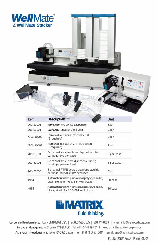
Item Description Unit201-10001 WellMate Microplate Dispenser Each
201-20001 WellMate Stacker Base Unit Each
*501-30005 Removable Stacker Chimney, Tall (2 required)
Each
*501-30006 Removable Stacker Chimney, Short (2 required)
Each
201-30001 8-channel standard bore disposable tubing cartridge, pre-sterilized
5 per Case
201-30001 8-channel small bore disposable tubing cartridge, pre-sterilized
5 per Case
201-30003 8-channel PTFE-coated stainless steel tip cartridge, reusable, pre-sterilized
Each
4954 Automation friendly universal polystyrene lid, clear, sterile for 96 & 384 well plates
80/case
4955 Automation friendly universal polystyrene lid, black, sterile for 96 & 384 well plates
80/case

70
Index
384-well plate, aligning for stackers, 3296-well plate, aligning for stackers, 31accessories, 69adjust dispensing speed, 36adjust stage X-position, 34back step, 37, 38, 55chemical compatibility, 51chimney support brackets, 3, 22columns, plate, selecting for fi ll, 25COM 1 port, 22, 53COM 2 port, 22commands, RS-232for remote device activation, 53sample commands, 61–63table of commands, 55–60communication error messages, 60confi guring the device, 15contact information, 65customer service, 65dispense accuracy, 9dispense pattern, setting, 25dispense precision, 9dispense volumerecommended, 9, 10setting, 26dispensing speed, adjusting, 36EPROM chip, 3, 21error, 44C001, 45command wrong format, 60dispensing between wells, 45E001, 44E002, 44E003, 44E005, 45E01, 60
E02, 60E03, 60E04, 60E99, 60plate type change, 44plate type change, RS-232 comm, 53-60pump cover open, 44pump cover open, RS-232 comm, 58stage doesn’t move or doesn’t home, 44stage doesn’t return, 44stage not at home, RS-232 comm, 58stage not at start, RS-232 comm, 58error messages, communication, 60error, communication, 60hazards and precautions, 12helpful hints, 43instrumentoperation, programmatic, 25overview, 2specifi cations, 9keypad, 6keys, description, 6maintenance. See tubing cartridgememory, saving programs in, 25microplates, setting up, 18modes, setting in programs, 25nozzle height spacer guide, using, 20nozzle tipsaligning with wells, 31cleaning, 39leveling with stage, 16nozzle-height reference guide, using, 19
Index

71
®
Index
nozzle-height spacer guide, using, 20operaterating manually, 33programmatic, 25Optical plate sensors, 8packing list, 68plate carriage. See stage plate setup12-well, 4824-well, 4948-well, 506-well, 47plate stage, aligning, 17–19plates, setting up, 17power cord, attaching, 22programs creating, loading, and saving, 25running from memory, 27setting modes in, 26protocol, serial port specifi cations for, 53pump count, 37, 38pump pause, 37, 38pump speed, adjusting. See dispensing speed, adjustingpump speed, normal operating, 57replacement parts, 69returning instrument, 66–67RS-232 commands, 53–60communication error messages, 60for remote device activation, 53protocol for, 54sample command, 61–63table of commands, 55–60wait time between, 59RS232 interface, 8safety, 11schematics, 64serial port communication specifi cations, 54–60small-bore tubing, 2
small-bore tubing, specifi cations, 10specifi cations, 9instrument, 4small-bore tubing cartridge, 10stacker unit, 8standard-bore tubing, 9specifi cations, serial port, 54–60stacker chimneys, 8stacker height, 11stacker unit, 1, 3, 8, 11, 20, 21, 22, 31stackers, installing, 21–23stackers, setting up and operating, 31–33stageadjusting X position, 34attaching, 16leveling with nozzle tips, 19standard-bore tubing, 2, 9timed prime, 38tips, nozzle. See nozzle tips troubleshooting, 45tube sets. See tubing cartridgetubing assembly. See tubing cartridgetubing cartridge, 39–43chemicals compatible with, 51cleaning, 39, 42cleaning after use, 34, 39helpful hints, 43installing, 13leaving in resting position, 34priming, 23, 40recalibration, 40small bore, dispense accuracy for, 10small bore, precision limit for, 10small bore, specifi cations for, 10standard bore, dispense accuracy for, 9

72
Index
standard bore, precision limit for, 9standard bore, specifi cations for, 9wait time, between RS-232 commands, 59warnings, 12warranty, 66waste reservoir, 8, 17, 21
waste-fl uid vessel, attaching, 17
wells, plate, selecting for fi ll, 26
X-axis stage position, 25, 31, 34
Y-axis arm, 3, 19, 32, 40, 68Y-axis stage, aligning for
stackers, 29, 31, 32

73
®
Notes

74
Notes
Item Description Unit201-10001 WellMate Microplate Dispenser Each
201-20001 WellMate Stacker Base Unit Each
*501-30005 Removable Stacker Chimney, Tall
(2 required)Each
*501-30006Removable Stacker Chimney, Short
(2 required)Each
201-300018-channel standard bore disposable tubing
cartridge, pre-sterilized5 per Case
201-300018-channel small bore disposable tubing
cartridge, pre-sterilized5 per Case
201-300038-channel PTFE-coated stainless steel tip
cartridge, reusable, pre-sterilizedEach
4954Automation friendly universal polystyrene lid,
clear, sterile for 96 & 384 well plates80/case
4955Automation friendly universal polystyrene lid,
black, sterile for 96 & 384 well plates80/case
Corporate Headquarters: Hudson, NH 03051 USA | Tel: 603.595.0505 | 800.345.0206 | email: [email protected]
European Headquarters: Cheshire SK9 3LP UK | Tel: +44 (0) 161 486 2110 | email: [email protected]
Asia Pacific Headquarters: Tokyo 101-0032 Japan | Tel: +81 (0)3 5687 5787 | email: [email protected]
& WellMate Stacker
Part No. 22674 Rev.A Printed 06/06