Embed Size (px)
Citation preview
HUAWEI OceanStor V3 Series Storage Systems
Technical Training Slides
1
Contents
Key technologies
Application scenarios
Hardware architecture
4
2
3
Introduction1
2
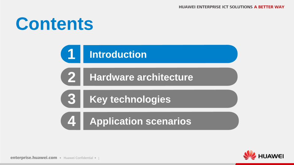
HUAWEI OceanStor V3 series storage systems
5300 V3 5500 V3 5600 V3 5800 V3 6800 V3 6900 V3
Unified software/hardware/management platform
3
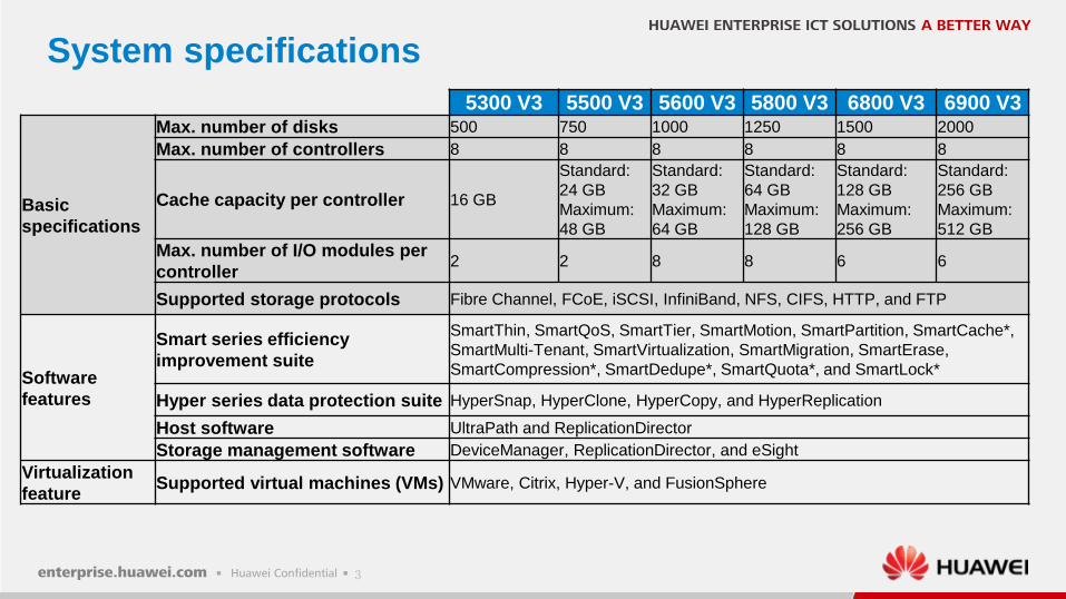
System specifications
5300 V3 5500 V3 5600 V3 5800 V3 6800 V3 6900 V3
Basic
specifications
Max. number of disks 500 750 1000 1250 1500 2000
Max. number of controllers 8 8 8 8 8 8
Cache capacity per controller 16 GB
Standard:
24 GB
Maximum:
48 GB
Standard:
32 GB
Maximum:
64 GB
Standard:
64 GB
Maximum:
128 GB
Standard:
128 GB
Maximum:
256 GB
Standard:
256 GB
Maximum:
512 GB
Max. number of I/O modules per
controller2 2 8 8 6 6
Supported storage protocols Fibre Channel, FCoE, iSCSI, InfiniBand, NFS, CIFS, HTTP, and FTP
Software
features
Smart series efficiency
improvement suite
SmartThin, SmartQoS, SmartTier, SmartMotion, SmartPartition, SmartCache*,
SmartMulti-Tenant, SmartVirtualization, SmartMigration, SmartErase,
SmartCompression*, SmartDedupe*, SmartQuota*, and SmartLock*
Hyper series data protection suite HyperSnap, HyperClone, HyperCopy, and HyperReplication
Host software UltraPath and ReplicationDirector
Storage management software DeviceManager, ReplicationDirector, and eSight
Virtualization
featureSupported virtual machines (VMs) VMware, Citrix, Hyper-V, and FusionSphere
4
Contents
Key technologies
Application scenarios
Hardware architecture
4
2
3
Introduction1
5
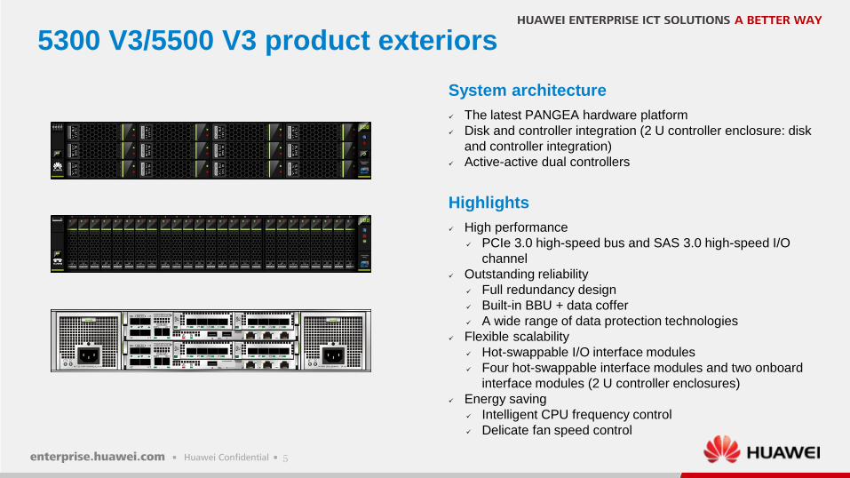
5300 V3/5500 V3 product exteriors
System architecture
The latest PANGEA hardware platform
Disk and controller integration (2 U controller enclosure: disk
and controller integration)
Active-active dual controllers
Highlights
High performance
PCIe 3.0 high-speed bus and SAS 3.0 high-speed I/O
channel
Outstanding reliability
Full redundancy design
Built-in BBU + data coffer
A wide range of data protection technologies
Flexible scalability
Hot-swappable I/O interface modules
Four hot-swappable interface modules and two onboard
interface modules (2 U controller enclosures)
Energy saving
Intelligent CPU frequency control
Delicate fan speed control
6
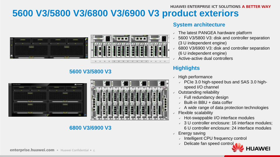
5600 V3/5800 V3/6800 V3/6900 V3 product exteriorsSystem architecture
The latest PANGEA hardware platform
5600 V3/5800 V3: disk and controller separation
(3 U independent engine)
6800 V3/6900 V3: disk and controller separation
(6 U independent engine)
Active-active dual controllers
Highlights
High performance
PCIe 3.0 high-speed bus and SAS 3.0 high-
speed I/O channel
Outstanding reliability
Full redundancy design
Built-in BBU + data coffer
A wide range of data protection technologies
Flexible scalability
Hot-swappable I/O interface modules
3 U controller enclosure: 16 interface modules;
6 U controller enclosure: 24 interface modules
Energy saving
Intelligent CPU frequency control
Delicate fan speed control
5600 V3/5800 V3
6800 V3/6900 V3
7
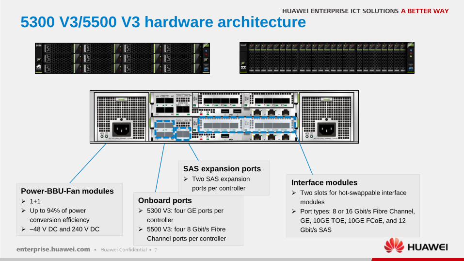
5300 V3/5500 V3 hardware architecture
Power-BBU-Fan modules
1+1
Up to 94% of power
conversion efficiency
–48 V DC and 240 V DC
Interface modules
Two slots for hot-swappable interface
modules
Port types: 8 or 16 Gbit/s Fibre Channel,
GE, 10GE TOE, 10GE FCoE, and 12
Gbit/s SAS
Onboard ports
5300 V3: four GE ports per
controller
5500 V3: four 8 Gbit/s Fibre
Channel ports per controller
SAS expansion ports
Two SAS expansion
ports per controller
8
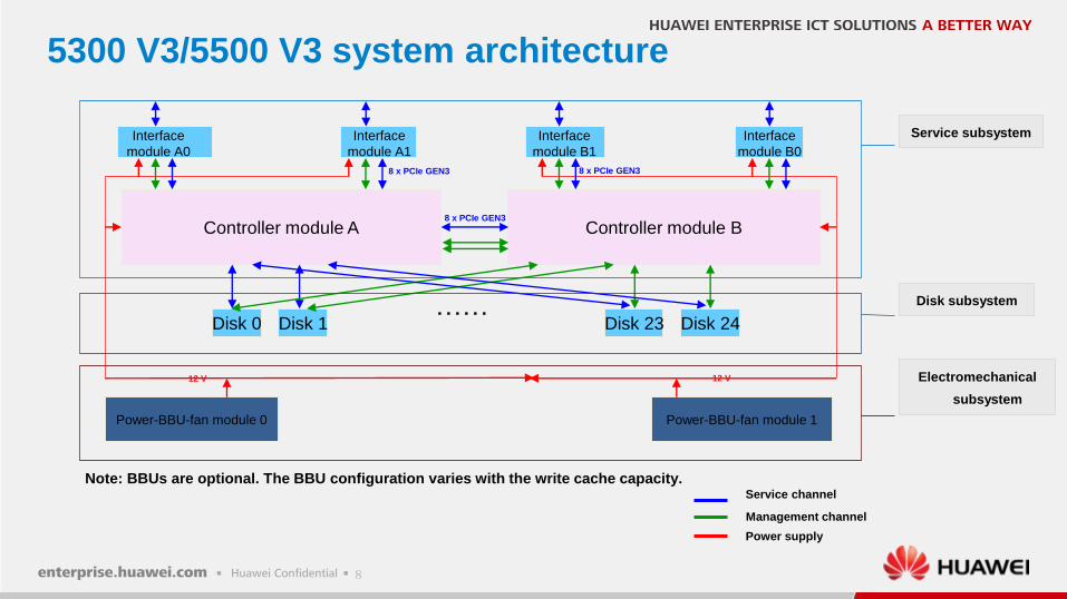
5300 V3/5500 V3 system architecture
Service subsystem
Service channel
Management channel
Power supply
8 x PCIe GEN3
Power-BBU-fan module 0 Power-BBU-fan module 1
Controller module B
Electromechanical
subsystem
8 x PCIe GEN3
12 V 12 V
8 x PCIe GEN3
Controller module A
Note: BBUs are optional. The BBU configuration varies with the write cache capacity.
……Disk 0 Disk 1 Disk 23 Disk 24
Disk subsystem
Interface
module A0
Interface
module A1
Interface
module B1
Interface
module B0
9
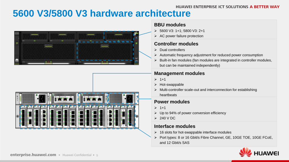
5600 V3/5800 V3 hardware architectureBBU modules 5600 V3: 1+1; 5800 V3: 2+1
AC power failure protection
Controller modules Dual controllers
Automatic frequency adjustment for reduced power consumption
Built-in fan modules (fan modules are integrated in controller modules,
but can be maintained independently)
Management modules 1+1
Hot-swappable
Multi-controller scale-out and interconnection for establishing
heartbeats
Power modules 1+1
Up to 94% of power conversion efficiency
240 V DC
Interface modules 16 slots for hot-swappable interface modules
Port types: 8 or 16 Gbit/s Fibre Channel, GE, 10GE TOE, 10GE FCoE,
and 12 Gbit/s SAS
10
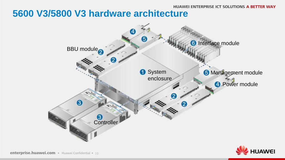
5600 V3/5800 V3 hardware architecture
System
enclosure
BBU module
Controller
Power module
Management module
Interface module
11
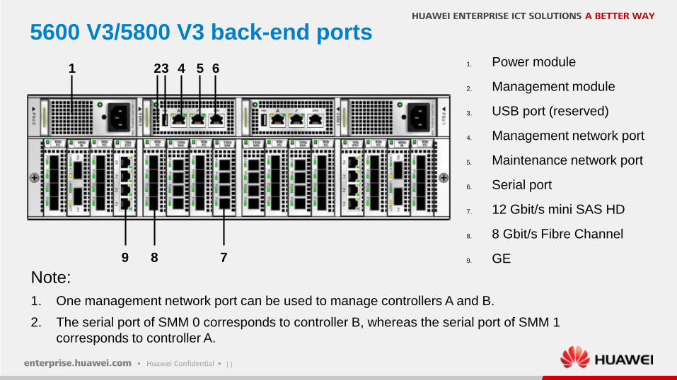
5600 V3/5800 V3 back-end ports
1 23 54 6
789
1. Power module
2. Management module
3. USB port (reserved)
4. Management network port
5. Maintenance network port
6. Serial port
7. 12 Gbit/s mini SAS HD
8. 8 Gbit/s Fibre Channel
9. GE
Note:
1. One management network port can be used to manage controllers A and B.
2. The serial port of SMM 0 corresponds to controller B, whereas the serial port of SMM 1
corresponds to controller A.
12
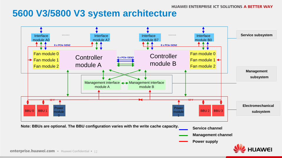
5600 V3/5800 V3 system architecture
Service subsystem
Service channel
Management channel
Power supply
8 x PCIe GEN3
BBU 0 BBU 1 BBU 2 BBU 3
Management
subsystem
Electromechanical
subsystem
8 x PCIe GEN2
12 V 12 V
……
8 x PCIe GEN2
……
Fan module 0
Fan module 2
Fan module 1
Fan module 0
Fan module 2
Fan module 1
Note: BBUs are optional. The BBU configuration varies with the write cache capacity.
Controller
module A
Controller
module B
Management interface
module A
Management interface
module B
Power
module
1
Power
module
0
Interface
module A0
Interface
module A7
Interface
module B7
Interface
module B0
13
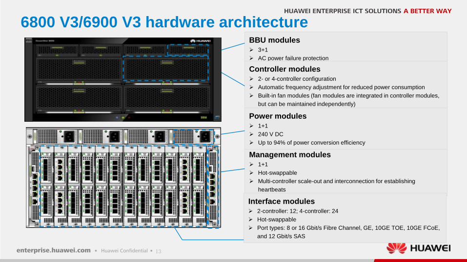
6800 V3/6900 V3 hardware architectureBBU modules 3+1
AC power failure protection
Controller modules 2- or 4-controller configuration
Automatic frequency adjustment for reduced power consumption
Built-in fan modules (fan modules are integrated in controller modules,
but can be maintained independently)
Management modules 1+1
Hot-swappable
Multi-controller scale-out and interconnection for establishing
heartbeats
Power modules 1+1
240 V DC
Up to 94% of power conversion efficiency
Interface modules 2-controller: 12; 4-controller: 24
Hot-swappable
Port types: 8 or 16 Gbit/s Fibre Channel, GE, 10GE TOE, 10GE FCoE,
and 12 Gbit/s SAS
14
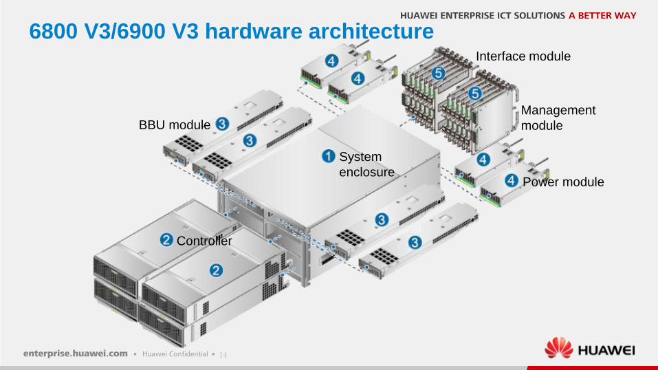
6800 V3/6900 V3 hardware architecture
System
enclosure
BBU module
Controller
Power module
Management
module
Interface module
15
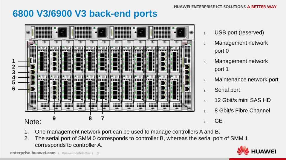
6800 V3/6900 V3 back-end ports
1. USB port (reserved)
2. Management network
port 0
3. Management network
port 1
4. Maintenance network port
5. Serial port
6. 12 Gbit/s mini SAS HD
7. 8 Gbit/s Fibre Channel
8. GENote:
1. One management network port can be used to manage controllers A and B.
2. The serial port of SMM 0 corresponds to controller B, whereas the serial port of SMM 1
corresponds to controller A.
1
7
23456
89
16
6800 V3/6900 V3 system architecture
Service
subsystem
8 x PCIe GEN3
Controller module B
Management
subsystem
Electromechanical
subsystem
8 x PCIe GEN3
12 V 12 V
……
8 x PCIe GEN3
……
Controller module A
8 x PCIe GEN3
Controller module D
8 x PCIe GEN3
……
8 x PCIe GEN3
……
Controller module C
Fan module 0
Fan module 2
Fan module 1
Fan module 0
Fan module 2
Fan module 1
Fan module 0
Fan module 2
Fan module 1
Fan module 0
Fan module 2
Fan module 1
Management interface
module A
Management interface
module B
BBU 0 BBU 1 BBU 2 BBU 3Power
module
3
Power
module
0
Power
module
1
Power
module
2
Interface
module A0
Interface
module A5
Interface
module B5
Interface
module B0
Interface
module A0
Interface
module A5
Interface
module B5
Interface
module B0
17
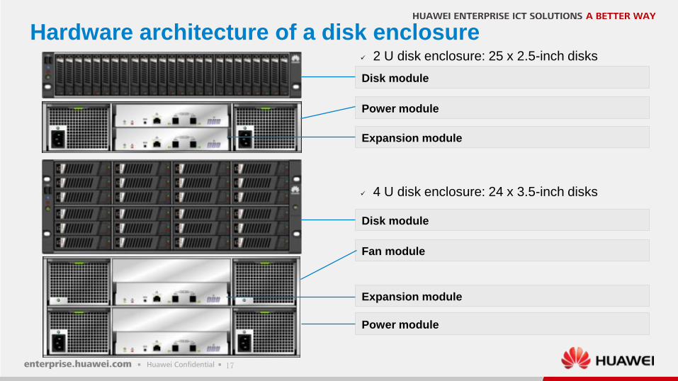
Hardware architecture of a disk enclosure
Disk module
Power module
Expansion module
Disk module
Fan module
Expansion module
Power module
4 U disk enclosure: 24 x 3.5-inch disks
2 U disk enclosure: 25 x 2.5-inch disks
18
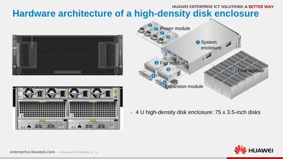
Hardware architecture of a high-density disk enclosure
System
enclosure
Power module
Fan module
Expansion module
Disk module
4 U high-density disk enclosure: 75 x 3.5-inch disks
19
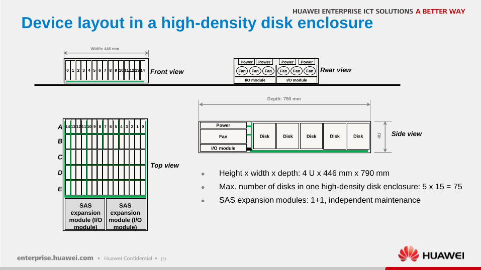
Device layout in a high-density disk enclosure
I/O moduleI/O module
Power PowerPower Power
Width: 446 mm
I/O module
Fan
Power
Disk DiskDisk Disk Disk 4U
Depth: 790 mm
Height x width x depth: 4 U x 446 mm x 790 mm
Max. number of disks in one high-density disk enclosure: 5 x 15 = 75
SAS expansion modules: 1+1, independent maintenance
Fan FanFan Fan FanFan43210 13121110985 76 14 Front view
Top view
Rear view
Side viewA 1011121314 1234569 78 0
B
C
D
E
SAS
expansion
module (I/O
module)
SAS
expansion
module (I/O
module)
20
Contents
Key technologies
Application scenarios
Hardware architecture
4
2
3
Introduction1
21
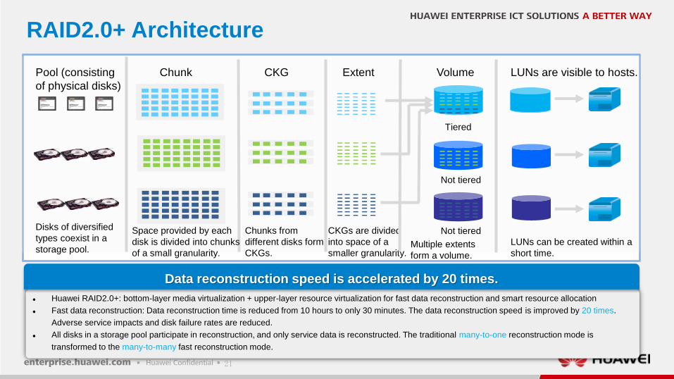
RAID2.0+ Architecture
Huawei RAID2.0+: bottom-layer media virtualization + upper-layer resource virtualization for fast data reconstruction and smart resource allocation
Fast data reconstruction: Data reconstruction time is reduced from 10 hours to only 30 minutes. The data reconstruction speed is improved by 20 times.
Adverse service impacts and disk failure rates are reduced.
All disks in a storage pool participate in reconstruction, and only service data is reconstructed. The traditional many-to-one reconstruction mode is
transformed to the many-to-many fast reconstruction mode.
Data reconstruction speed is accelerated by 20 times.
Pool (consisting
of physical disks)
Chunk CKG LUNs are visible to hosts.
Disks of diversified
types coexist in a
storage pool.
Space provided by each
disk is divided into chunks
of a small granularity.
Chunks from
different disks form
CKGs.
LUNs can be created within a
short time.
Extent
CKGs are divided
into space of a
smaller granularity.
Tiered
Not tiered
Volume
Multiple extents
form a volume.
Not tiered
22
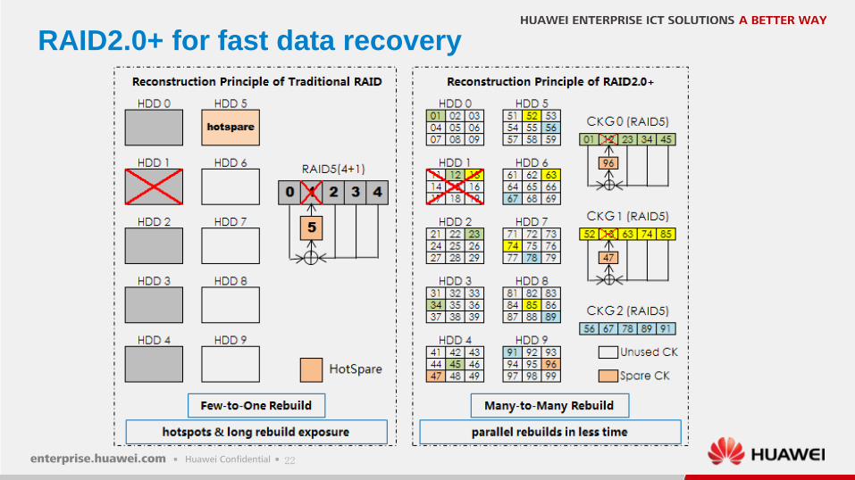
RAID2.0+ for fast data recovery
23
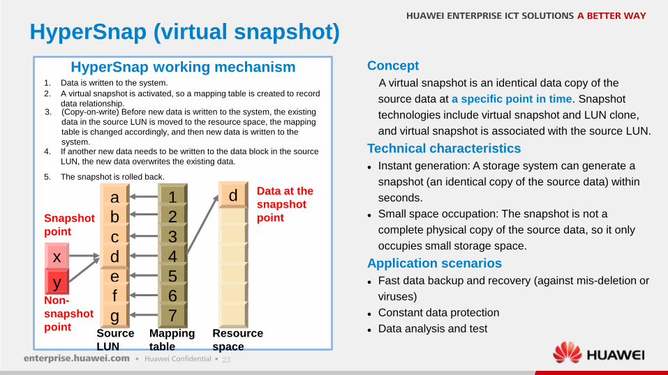
HyperSnap (virtual snapshot)
Concept
A virtual snapshot is an identical data copy of the
source data at a specific point in time. Snapshot
technologies include virtual snapshot and LUN clone,
and virtual snapshot is associated with the source LUN.
Technical characteristics
Instant generation: A storage system can generate a
snapshot (an identical copy of the source data) within
seconds.
Small space occupation: The snapshot is not a
complete physical copy of the source data, so it only
occupies small storage space.
Application scenarios
Fast data backup and recovery (against mis-deletion or
viruses)
Constant data protection
Data analysis and test
1. Data is written to the system.
ab
c
e
f
gSource
LUN
Resource
space
2. A virtual snapshot is activated, so a mapping table is created to record
data relationship.
12
3
4
5
6
7Mapping
table
3. (Copy-on-write) Before new data is written to the system, the existing
data in the source LUN is moved to the resource space, the mapping
table is changed accordingly, and then new data is written to the
system.
dx
4. If another new data needs to be written to the data block in the source
LUN, the new data overwrites the existing data.
y
5. The snapshot is rolled back.
d
Snapshot
point
Non-
snapshot
point
Data at the
snapshot
point
HyperSnap working mechanism
24
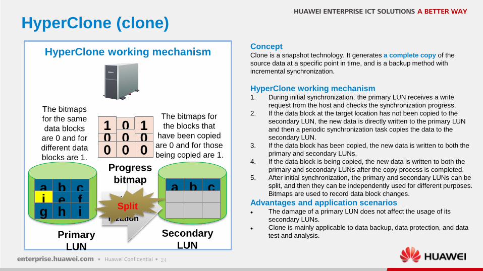
HyperClone (clone)
HyperClone working mechanism1. During initial synchronization, the primary LUN receives a write
request from the host and checks the synchronization progress.
2. If the data block at the target location has not been copied to the
secondary LUN, the new data is directly written to the primary LUN
and then a periodic synchronization task copies the data to the
secondary LUN.
3. If the data block has been copied, the new data is written to both the
primary and secondary LUNs.
4. If the data block is being copied, the new data is written to both the
primary and secondary LUNs after the copy process is completed.
5. After initial synchronization, the primary and secondary LUNs can be
split, and then they can be independently used for different purposes.
Bitmaps are used to record data block changes.
Advantages and application scenarios The damage of a primary LUN does not affect the usage of its
secondary LUNs.
Clone is mainly applicable to data backup, data protection, and data
test and analysis.Primary
LUN
Secondary
LUN
0 0 01 1 11 1 1
a b cd e fg h i
a b cInitial
synchro
nization
jk
The bitmaps for
the blocks that
have been copied
are 0 and for those
being copied are 1.
j
j
k
0
e
ll
0
fg h i
Split
mn
00 0 0
1 1
The bitmaps
for the same
data blocks
are 0 and for
different data
blocks are 1.
HyperClone working mechanismConceptClone is a snapshot technology. It generates a complete copy of the
source data at a specific point in time, and is a backup method with
incremental synchronization.
Progress
bitmap
25
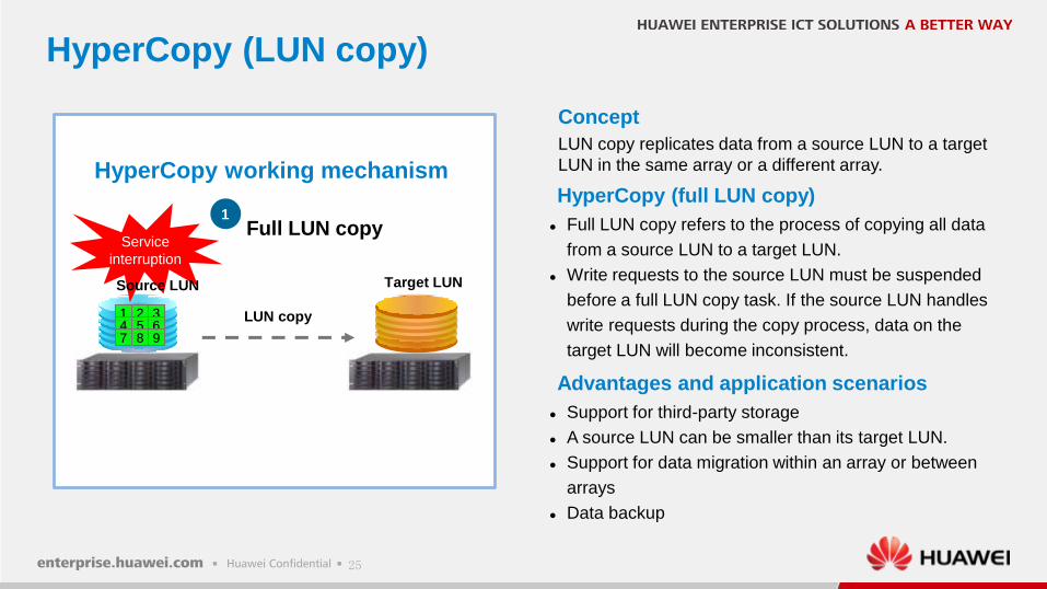
HyperCopy (LUN copy)
Concept
LUN copy replicates data from a source LUN to a target
LUN in the same array or a different array.
HyperCopy (full LUN copy)
Full LUN copy refers to the process of copying all data
from a source LUN to a target LUN.
Write requests to the source LUN must be suspended
before a full LUN copy task. If the source LUN handles
write requests during the copy process, data on the
target LUN will become inconsistent.
Advantages and application scenarios
Support for third-party storage
A source LUN can be smaller than its target LUN.
Support for data migration within an array or between
arrays
Data backup
1Full LUN copy
Service
interruption
Source LUN Target LUN
LUN copy1 2 34 5 67 8 9
1 2 34 5 67 8 9
HyperCopy working mechanism
26
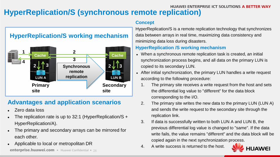
HyperReplication/S (synchronous remote replication)
Concept
HyperReplication/S is a remote replication technology that synchronizes
data between arrays in real time, maximizing data consistency and
minimizing data loss during disasters.
HyperReplication /S working mechanism
When a synchronous remote replication task is created, an initial
synchronization process begins, and all data on the primary LUN is
copied to its secondary LUN.
After initial synchronization, the primary LUN handles a write request
according to the following procedure:
1. The primary site receives a write request from the host and sets
the differential log value to "different" for the data block
corresponding to the I/O.
2. The primary site writes the new data to the primary LUN (LUN A)
and sends the write request to the secondary site through the
replication link.
3. If data is successfully written to both LUN A and LUN B, the
previous differential log value is changed to "same". If the data
write fails, the value remains "different" and the data block will be
copied again in the next synchronization process.
4. A write success is returned to the host.
Synchronous
remote
replication
Cache Cache
LUN A LUN B
Primary
site
Secondary
site
1
2 2
2
3
3
34
HyperReplication/S working mechanism
Advantages and application scenarios
Zero data loss
The replication rate is up to 32:1 (HyperReplication/S +
HyperReplication/A).
The primary and secondary arrays can be mirrored for
each other.
Applicable to local or metropolitan DR
27
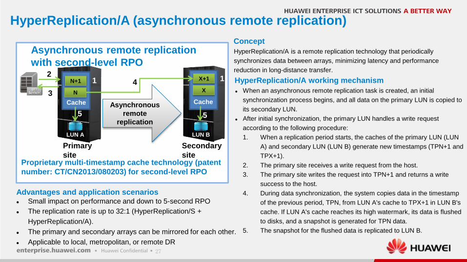
HyperReplication/A (asynchronous remote replication)
Concept
HyperReplication/A is a remote replication technology that periodically
synchronizes data between arrays, minimizing latency and performance
reduction in long-distance transfer.
HyperReplication/A working mechanism
When an asynchronous remote replication task is created, an initial
synchronization process begins, and all data on the primary LUN is copied to
its secondary LUN.
After initial synchronization, the primary LUN handles a write request
according to the following procedure:
1. When a replication period starts, the caches of the primary LUN (LUN
A) and secondary LUN (LUN B) generate new timestamps (TPN+1 and
TPX+1).
2. The primary site receives a write request from the host.
3. The primary site writes the request into TPN+1 and returns a write
success to the host.
4. During data synchronization, the system copies data in the timestamp
of the previous period, TPN, from LUN A's cache to TPX+1 in LUN B's
cache. If LUN A's cache reaches its high watermark, its data is flushed
to disks, and a snapshot is generated for TPN data.
5. The snapshot for the flushed data is replicated to LUN B.
Asynchronous
remote
replication
Cache Cache
LUN A LUN B
Primary
site
Secondary
site
12
5
3
5
4N+1
N
X+1
X
1
Proprietary multi-timestamp cache technology (patent
number: CT/CN2013/080203) for second-level RPO
Asynchronous remote replication
with second-level RPO
Advantages and application scenarios Small impact on performance and down to 5-second RPO
The replication rate is up to 32:1 (HyperReplication/S +
HyperReplication/A).
The primary and secondary arrays can be mirrored for each other.
Applicable to local, metropolitan, or remote DR
28
HyperMirrorHyperMirror is a data backup technology. It creates multiple
physical mirror copies for a LUN to achieve continuous LUN
backup and protection. In this way, the reliability and
availability of the LUN are significantly improved.
Working principle
Creating a mirrored LUN
1. Converts a local LUN or an external LUN into a mirrored
LUN, creates a mirror copy, and adds a mirror copy for
the mirrored LUN for redundancy.
Performing synchronization
1. Initial synchronization: Replicates all data from the
mirrored LUN to the mirror copy and writes data
concurrently to both the mirrored LUN and mirror copy.
2. Incremental synchronization: Replicates data increment
from the mirrored LUN to the mirror copy after the mirror
copy is recovered from Splitting or Interruption.
Implementing splitting
1. The mirror copy is unavailable after splitting, but is
available before splitting.
1
2 3
Common
LUN
Common
LUN
Mirrored
LUN
Mirror
copy
Mirror
copy
A B
Mirrored LUN
creating
Initial
synchronization
Splitting
Incremental
synchronization
When synchronization
between the mirrored LUN
and mirror copy needs to be
suspended
After a mirror
copy is created or
added
When the mirror copy
is recovered from
Interruption
When data synchronization
between the mirrored LUN
and mirror copy needs to be
resumed
When synchronization
between the mirrored LUN
and mirror copy needs to be
suspended
29
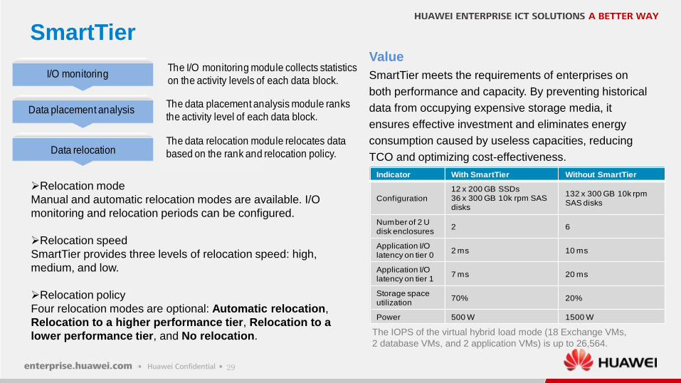
SmartTier
Relocation mode
Manual and automatic relocation modes are available. I/O
monitoring and relocation periods can be configured.
Relocation speed
SmartTier provides three levels of relocation speed: high,
medium, and low.
Relocation policy
Four relocation modes are optional: Automatic relocation,
Relocation to a higher performance tier, Relocation to a
lower performance tier, and No relocation.
Value
SmartTier meets the requirements of enterprises on
both performance and capacity. By preventing historical
data from occupying expensive storage media, it
ensures effective investment and eliminates energy
consumption caused by useless capacities, reducing
TCO and optimizing cost-effectiveness.
The IOPS of the virtual hybrid load mode (18 Exchange VMs,
2 database VMs, and 2 application VMs) is up to 26,564.
Indicator With SmartTier Without SmartTier
Configuration
12 x 200 GB SSDs36 x 300 GB 10k rpm SAS disks
132 x 300 GB 10k rpm SAS disks
Number of 2 U disk enclosures
2 6
Application I/O latency on tier 0
2 ms 10 ms
Application I/O latency on tier 1
7 ms 20 ms
Storage spaceutilization
70% 20%
Power 500 W 1500 W
I/O monitoring
Data placement analysis
Data relocation
The I/O monitoring module collects statistics
on the activity levels of each data block.
The data relocation module relocates data
based on the rank and relocation policy.
The data placement analysis module ranks
the activity level of each data block.
30
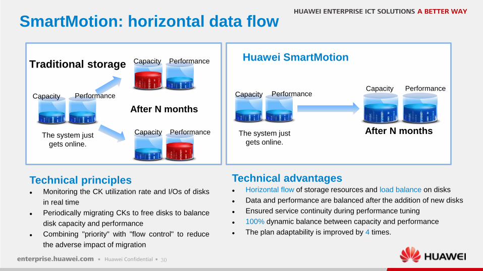
SmartMotion: horizontal data flow
Traditional storageHuawei SmartMotion
After N months
Capacity Performance
After N months
Capacity Performance
Capacity Performance
Capacity Performance
The system just
gets online.
Capacity Performance
The system just
gets online.
Technical principles Monitoring the CK utilization rate and I/Os of disks
in real time
Periodically migrating CKs to free disks to balance
disk capacity and performance
Combining "priority" with "flow control" to reduce
the adverse impact of migration
Technical advantages Horizontal flow of storage resources and load balance on disks
Data and performance are balanced after the addition of new disks
Ensured service continuity during performance tuning
100% dynamic balance between capacity and performance
The plan adaptability is improved by 4 times.
31
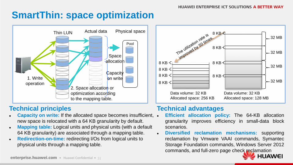
SmartThin: space optimization
32 MB
32 MB
32 MB
32 MB8 KB
Data volume: 32 KB
Allocated space: 256 KB
Data volume: 32 KB
Allocated space: 128 MB
8 KB
8 KB
8 KB 8 KB
8 KB
8 KB
8 KB
1. Write
operation
Thin LUN
2. Space allocation or
optimization according
to the mapping table.
Pool
Capacity
on write
Space
allocation
Physical spaceActual data
Technical principles Capacity on write: If the allocated space becomes insufficient,
new space is relocated with a 64 KB granularity by default.
Mapping table: Logical units and physical units (with a default
64 KB granularity) are associated through a mapping table.
Redirection-on-time: redirecting I/Os from logical units to
physical units through a mapping table.
Technical advantages Efficient allocation policy: The 64-KB allocation
granularity improves efficiency in small-data block
scenarios.
Diversified reclamation mechanisms: supporting
reclamation by Vmware VAAI commands, Symantec
Storage Foundation commands, Windows Server 2012
commands, and full-zero page check reclamation
32
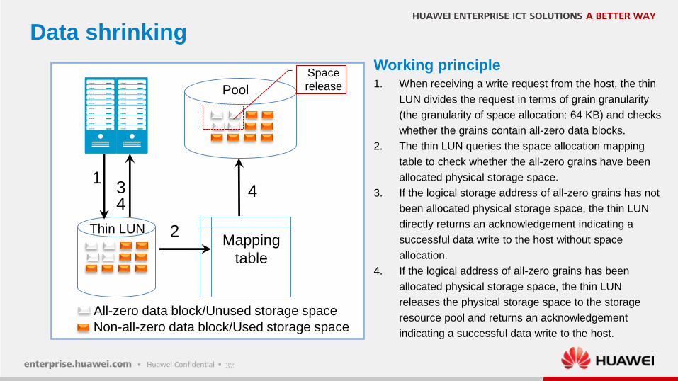
All-zero data block/Unused storage space
Non-all-zero data block/Used storage space
Working principle1. When receiving a write request from the host, the thin
LUN divides the request in terms of grain granularity
(the granularity of space allocation: 64 KB) and checks
whether the grains contain all-zero data blocks.
2. The thin LUN queries the space allocation mapping
table to check whether the all-zero grains have been
allocated physical storage space.
3. If the logical storage address of all-zero grains has not
been allocated physical storage space, the thin LUN
directly returns an acknowledgement indicating a
successful data write to the host without space
allocation.
4. If the logical address of all-zero grains has been
allocated physical storage space, the thin LUN
releases the physical storage space to the storage
resource pool and returns an acknowledgement
indicating a successful data write to the host.
Thin LUNMapping
table
Pool
1
2
34
4
Space
release
Data shrinking
33
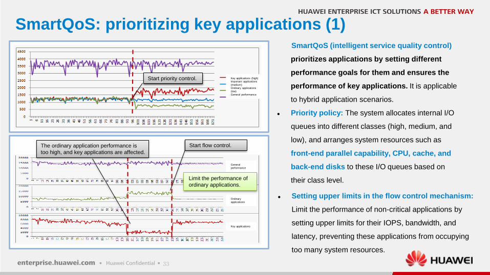
SmartQoS: prioritizing key applications (1)
Limit the performance of
ordinary applications.
Start flow control.The ordinary application performance is
too high, and key applications are affected.
Start priority control.
SmartQoS (intelligent service quality control)
prioritizes applications by setting different
performance goals for them and ensures the
performance of key applications. It is applicable
to hybrid application scenarios.
Priority policy: The system allocates internal I/O
queues into different classes (high, medium, and
low), and arranges system resources such as
front-end parallel capability, CPU, cache, and
back-end disks to these I/O queues based on
their class level.
Setting upper limits in the flow control mechanism:
Limit the performance of non-critical applications by
setting upper limits for their IOPS, bandwidth, and
latency, preventing these applications from occupying
too many system resources.
Key applications (high)
Important applications
(medium)
Ordinary applications
(low)
General performance
General
performance
Ordinary
applications
Key applications
34
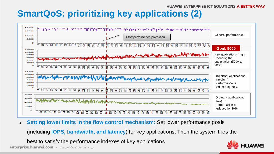
SmartQoS: prioritizing key applications (2)
Start performance protection.
Goal: 8000
Setting lower limits in the flow control mechanism: Set lower performance goals
(including IOPS, bandwidth, and latency) for key applications. Then the system tries the
best to satisfy the performance indexes of key applications.
General performance
Key applications (high)
Reaching the
expectation (5000 to
8000)
Important applications
(medium)
Performance is
reduced by 20%.
Ordinary applications
(low)
Performance is
reduced by 40%.
35
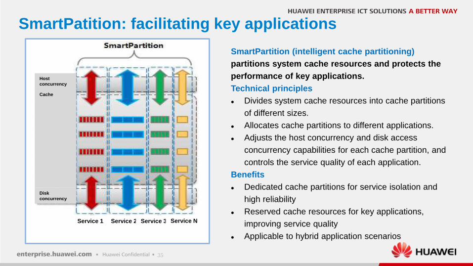
SmartPatition: facilitating key applications
SmartPartition (intelligent cache partitioning)
partitions system cache resources and protects the
performance of key applications.
Technical principles
Divides system cache resources into cache partitions
of different sizes.
Allocates cache partitions to different applications.
Adjusts the host concurrency and disk access
concurrency capabilities for each cache partition, and
controls the service quality of each application.
Benefits
Dedicated cache partitions for service isolation and
high reliability
Reserved cache resources for key applications,
improving service quality
Applicable to hybrid application scenarios
Service 1 Service 2 Service 3 Service N
Host
concurrency
Cache
Disk
concurrency
36
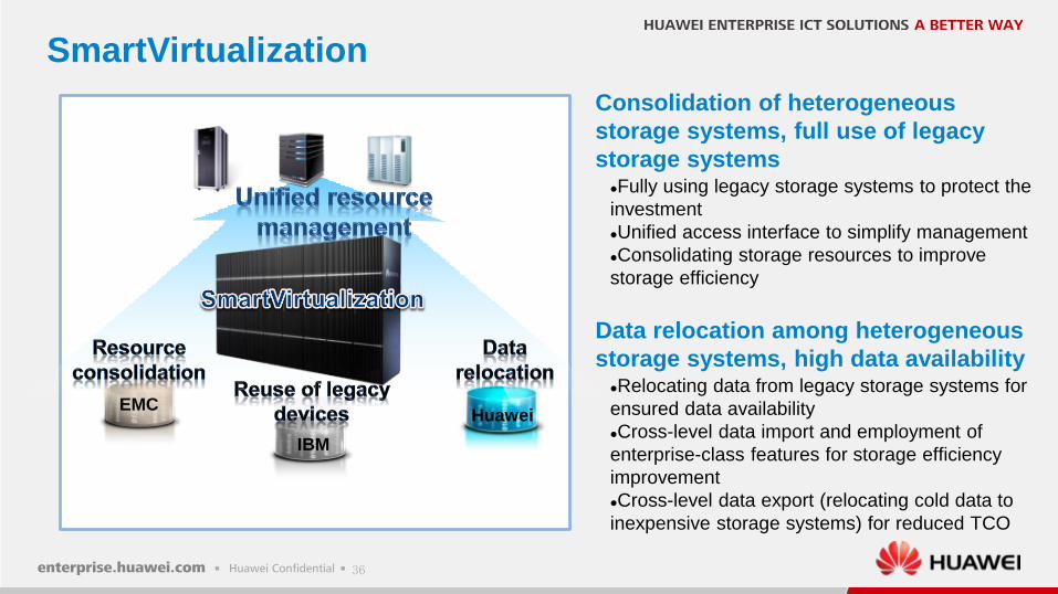
SmartVirtualization
EMC
IBM
Huawei
Consolidation of heterogeneous
storage systems, full use of legacy
storage systemsFully using legacy storage systems to protect the
investment
Unified access interface to simplify management
Consolidating storage resources to improve
storage efficiency
Data relocation among heterogeneous
storage systems, high data availabilityRelocating data from legacy storage systems for
ensured data availability
Cross-level data import and employment of
enterprise-class features for storage efficiency
improvement
Cross-level data export (relocating cold data to
inexpensive storage systems) for reduced TCO
37
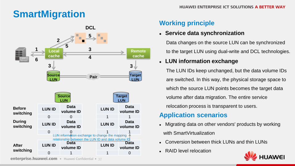
SmartMigration
Application scenarios
Migrating data on other vendors' products by working
with SmartVirtualization
Conversion between thick LUNs and thin LUNs
RAID level relocation
Working principle
Service data synchronization
Data changes on the source LUN can be synchronized
to the target LUN using dual-write and DCL technologies.
LUN information exchange
The LUN IDs keep unchanged, but the data volume IDs
are switched. In this way, the physical storage space to
which the source LUN points becomes the target data
volume after data migration. The entire service
relocation process is transparent to users.
Local
cache
1
3 3
3
46
Source
LUN
Remote
cache
52
5
DCL
Target
LUNPair
Source
LUN
Target
LUN
LUN IDData
volume ID
0 0
LUN IDData
volume ID
0 0
LUN IDData
volume ID
0 1
LUN IDData
volume ID
1 1
LUN IDData
volume ID
1 1
LUN IDData
volume ID
1 0
Before
switching
During
switching
After
switching
LUN information exchange to change the mapping
relationship between the LUN ID and data volume ID
38
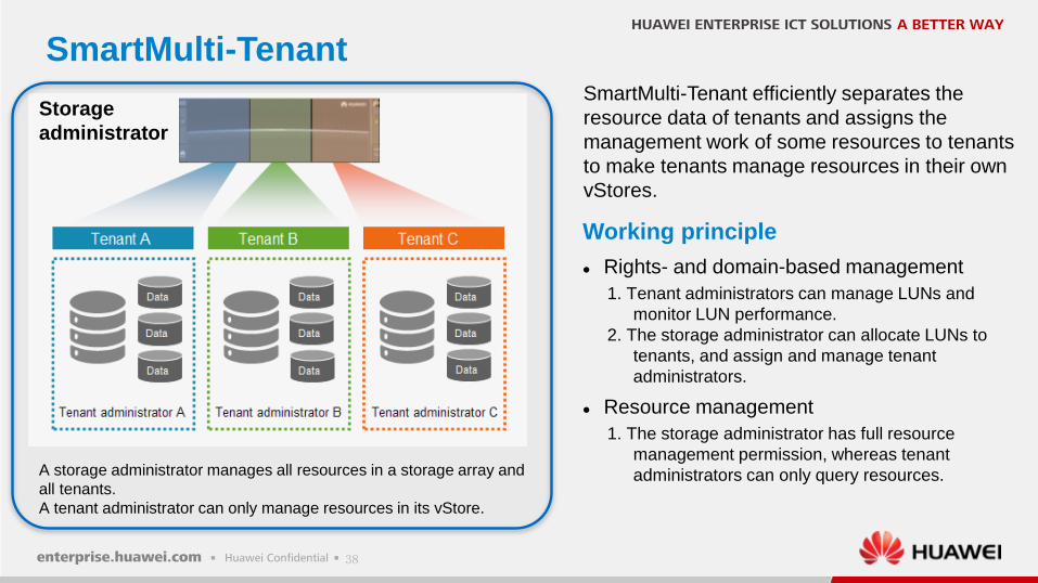
SmartMulti-Tenant
Storage
administrator
A storage administrator manages all resources in a storage array and
all tenants.
A tenant administrator can only manage resources in its vStore.
SmartMulti-Tenant efficiently separates the
resource data of tenants and assigns the
management work of some resources to tenants
to make tenants manage resources in their own
vStores.
Working principle
Rights- and domain-based management
1. Tenant administrators can manage LUNs and
monitor LUN performance.
2. The storage administrator can allocate LUNs to
tenants, and assign and manage tenant
administrators.
Resource management
1. The storage administrator has full resource
management permission, whereas tenant
administrators can only query resources.
39
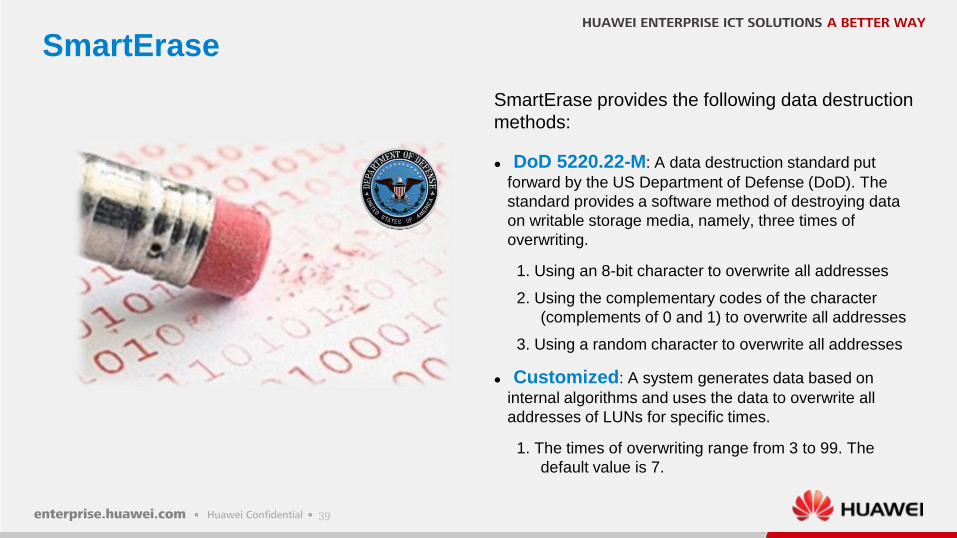
SmartErase
SmartErase provides the following data destruction
methods:
DoD 5220.22-M: A data destruction standard put
forward by the US Department of Defense (DoD). The
standard provides a software method of destroying data
on writable storage media, namely, three times of
overwriting.
1. Using an 8-bit character to overwrite all addresses
2. Using the complementary codes of the character
(complements of 0 and 1) to overwrite all addresses
3. Using a random character to overwrite all addresses
Customized: A system generates data based on
internal algorithms and uses the data to overwrite all
addresses of LUNs for specific times.
1. The times of overwriting range from 3 to 99. The
default value is 7.
40
Contents
Key technologies
Application scenarios
Hardware architecture
4
2
3
Introduction1
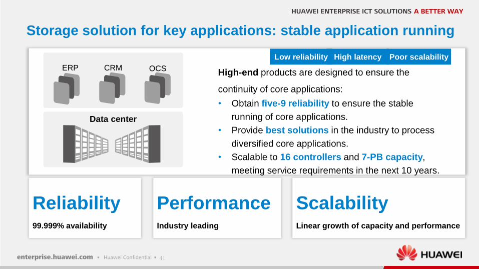
41
High-end products are designed to ensure the
continuity of core applications:
• Obtain five-9 reliability to ensure the stable
running of core applications.
• Provide best solutions in the industry to process
diversified core applications.
• Scalable to 16 controllers and 7-PB capacity,
meeting service requirements in the next 10 years.
Poor scalabilityHigh latency
Storage solution for key applications: stable application running
PerformanceIndustry leading
Reliability99.999% availability
ScalabilityLinear growth of capacity and performance
Data center
ERP CRM OCS
Low reliability
42
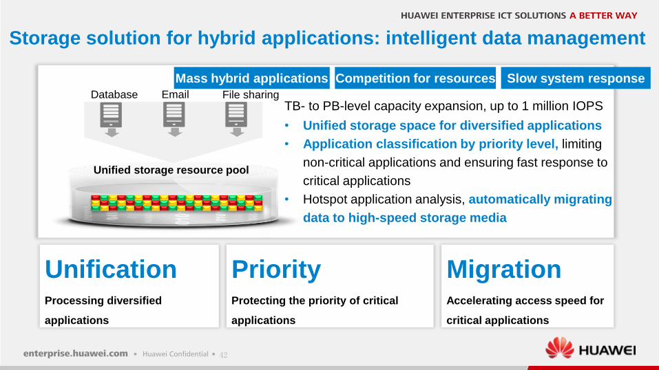
Storage solution for hybrid applications: intelligent data management
Database Email File sharing
Unified storage resource pool
Mass hybrid applications Competition for resources Slow system response
TB- to PB-level capacity expansion, up to 1 million IOPS
• Unified storage space for diversified applications
• Application classification by priority level, limiting
non-critical applications and ensuring fast response to
critical applications
• Hotspot application analysis, automatically migrating
data to high-speed storage media
PriorityProtecting the priority of critical
applications
UnificationProcessing diversified
applications
MigrationAccelerating access speed for
critical applications
43
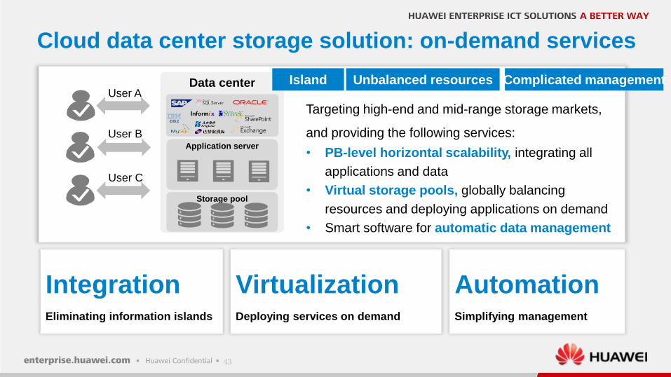
Targeting high-end and mid-range storage markets,
and providing the following services:
• PB-level horizontal scalability, integrating all
applications and data
• Virtual storage pools, globally balancing
resources and deploying applications on demand
• Smart software for automatic data management
Cloud data center storage solution: on-demand services
User A
User B
User C
VirtualizationDeploying services on demand
IntegrationEliminating information islands
AutomationSimplifying management
Data center
Application server
Storage pool
Unbalanced resourcesIsland Complicated management
44
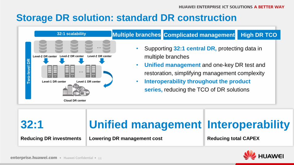
• Supporting 32:1 central DR, protecting data in
multiple branches
• Unified management and one-key DR test and
restoration, simplifying management complexity
• Interoperability throughout the product
series, reducing the TCO of DR solutions
32:1Reducing DR investments
Multiple branches High DR TCO
InteroperabilityReducing total CAPEX
Unified managementLowering DR management cost
Storage DR solution: standard DR construction
Complicated management
Level-2 DR center
Level-1 DR center Level-1 DR center
Cloud DR center
…
Tw
o-l
evel D
R
32:1 scalability
…
Level-2 DR center Level-2 DR center
Copyright©2014 Huawei Technologies Co., Ltd. All Rights Reserved.
The information in this document may contain predictive statements including, without limitation, statements regarding the future financial and operating results, future product
portfolio, new technology, etc. There are a number of factors that could cause actual results and developments to differ materially from those expressed or implied in the predictive
statements. Therefore, such information is provided for reference purpose only and constitutes neither an offer nor an acceptance. Huawei may change the information at any time
without notice.
HUAWEI ENTERPRISE ICT SOLUTIONS A BETTER WAY