Embed Size (px)
Citation preview

HTP America, Inc • 3200 Nordic Road • Arlington Heights, IL 60005-47291-800-USA-WELD • 847-357-0700 • FAX: 847-357-0744 • www.usaweld.com
HTP MIG 130Owner’s Manual
2
MANUFACTURER’S WARRANTY
It is expressly agreed that there are no warranties, expressed or implied, made by either theSalesman, Dealer, or HTP America, Inc. on products or parts furnished hereunder, except theManufacturer’s Warranty against defective materials or workmanship as follows:
HTP America, Inc. warrants each new HTP Mig 130 to be free from defects in material and work-manship under normal use and service for three years after delivery to the original purchase.HTP America, Inc. will repair and replace, at its factory, any part or parts thereof, products to bereturned to HTP America, Inc. with transportation charges prepaid and which its examinationshall disclose to its satisfaction to have been thus defective. This warranty being expressly in lieuof all other warranties, expressed or implied, and all other obligation or liabilities on its part andit neither assumes nor authorizes any other person to assume for it any other liability in connec-tion with the sale of its machines.
This warranty shall not apply to any welding machine which has been repaired or altered byunauthorized service departments in any way so as in the judgment of HTP America, Inc. toaffect its stability and reliability, nor which has been subjected to misuse, negligence or accident.
HTP America, Inc. shall not be liable in any event, unless HTP America, Inc. receives notice ofalleged breach of warranty within 30 days after the discovery, actual or construction allegedbreach of warranty specifying the claimed defect.
HTP America, Inc. has reserved the right to make changes in design or add any improvements toits products at any time without incurring any obligation to install same on equipment.
This warranty is void unless warranty card is sent to HTP America, Inc. within 15 days from thedate of purchase.
NOTE: Exclusions to Warranty:
1. The welding gun is warranted for a period of ninety (90) days against defects in materi-al and workmanship.
2. The swan neck, nozzle spring, contact tips, gas nozzles, and liners are consumableitems, WHICH CARRY NO WARRANTY.

3
TABLE OF CONTENTSWarranty ................................................................................2Introduction..........................................................................3Safety Summary..................................................................4
Safety Information ..........................................................4Shock Hazards ..................................................................5Flash Hazards ....................................................................5Fire Hazards........................................................................6Fume Hazards....................................................................7Compressed Gasses
and Equipment Hazards ............................................7Additional Safety Information ....................................8
Welder Specifications ......................................................9Description ........................................................................9Welder Operating Characteristics..............................9
Duty Cycle ......................................................................9Internal Thermal Protection ........................................9
Know Your Welder ..............................................................10Welder Installation ............................................................11
Power Source Connection ............................................11Power Requirements ..................................................11Connect to Power Source..........................................11Extension Cords ............................................................11
Assembling the Welder..................................................11Unpacking the Welder................................................11Packing List ....................................................................11Installing the Handle ..................................................11Installing the Feet ........................................................12Selecting Shielding Gas ............................................12Install the Shielding Gas ............................................12
Check the Gas Flow ........................................................13Align and Set the Drive Roller ....................................13Install the Welding Wire ................................................14
Set the Wire Drive Tension............................................16Installing Aluminium Wire ............................................16Change Polarity ................................................................16
Operation ..............................................................................18Controls and Indicators ................................................18
Power Switch ................................................................18Voltage Selector............................................................18Wire Speed Control......................................................18
Tuning in the Wire Speed..............................................18Learning to Weld..............................................................18Holding the Gun ..............................................................19Welding Techniques........................................................20
Moving the Gun............................................................20Types of Weld Beads....................................................20Welding Positions ........................................................21Multiple Pass Welding ................................................22Special Welding Methods..........................................23
Spot Welding..............................................................23Spot Welding Instructions ....................................23
Maintenance ........................................................................24General ................................................................................24Consumable Maintenance ..........................................24Maintaining the Contact Tip........................................24Maintaining the Nozzle ................................................24Testing for a Shorted Nozzle........................................25Replace a Gun Liner ........................................................25Preventive Maintenance................................................26Troubleshooting ..............................................................26
Parts List ................................................................................28Wiring Diagram ..................................................................32Suggested Settings ..........................................................33
4
TABLE OF CONTENTS
Every welder respects the tools with whichthey work. They know that the tools repre-sent years of constantly improved designsand developments. The true craftsman alsoknows that tools are dangerous if misused orabused.
Reading this operator’s manual before usingthe welder will enable you to do a better,safer job. Learn the welder’s applications andlimitations as well as the specific potentialhazards peculiar to welding.
IMPORTANT SAFETY INFORMATION
The following safety information is providedas guidelines to help you operate your newwelder under the safest possible conditions.Any equipment that uses electrical power canbe potentially dangerous to use when safetyor safe handling instructions are not knownor not followed. The following safety informa-tion is provided to give the user the informa-tion necessary for safe use and operation.
A procedure step preceded by a WARNING isan indication that the next step contains aprocedure that might be injurious to a personif proper safety precautions are not heeded.
A procedure preceded by a CAUTION is anindication that the next step contains a pro-cedure that might damage the equipmentbeing used.
A NOTE may be used before or after a proce-dure step to highlight or explain somethingin that step.
READ ALL SAFETY INSTRUCTIONS CARE-FULLY before attempting to install, operate,or service this welder. Failure to comply withthese instructions could result in personalinjury and/or property damage.
RETAIN THESE INSTRUCTIONS FOR FUTUREREFERENCE.
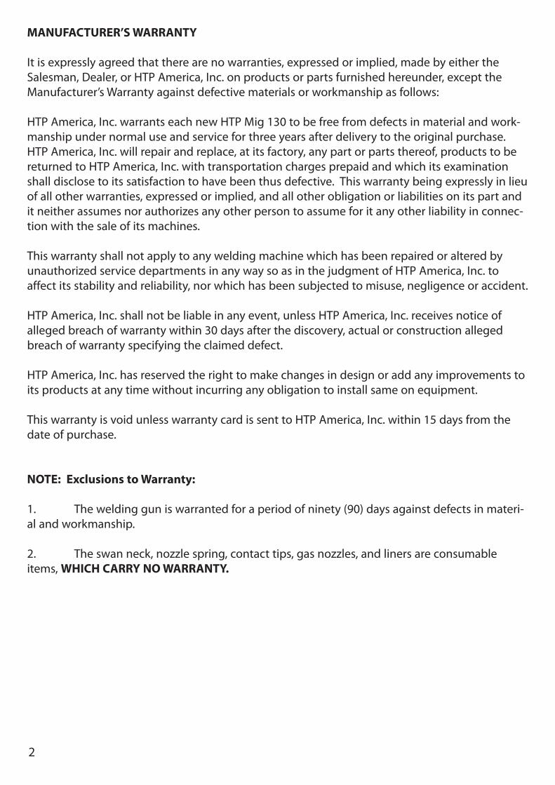
Note: • The following safety alert symbols identify
important safety messages in this manual.• When you see one of the symbols shown
here, be alert to the possibility of personalinjury and carefully read the message thatfollows.
This symbol indicates that the pos-sibility of electric shock hazardexists during the operation of thestep(s) that follow.
This symbol indicates that the pos-sibility of fire hazard exists duringthe operation of the step(s) thatfollow.
This symbol indicates that the hel-met must be worn during thestep(s) that follow to protect againsteye damage and burns due to flashhazard.
This symbol indicates that the pos-sibility of toxic gas hazard existsduring operation of the step(s) thatfollow.
This symbol indicates that the pos-sibility of being burned by hot slagexists during operation of thestep(s) that follow.
This symbol indicates that the eyeprotection should be worn to pro-tect against flying debris in the fol-lowing step(s).
This symbol indicates that the pos-sibility of injury or death exists dueto improper handling and mainte-nance of compresses gas cylindersor regulators.
• Published standards on safety are avail-able. They are listed in ADDITIONAL SAFE-TY INFORMATION at the end of this SAFE-TY SUMMARY.
The National Electrical Code, OccupationSafety and Health Act regulations, localindustrial codes and local inspection require-ments also provide a basis for equipmentinstallation, use, and service.
SAFETY SUMMARY
5
SHOCK HAZARD
WARNING
ELECTRIC SHOCK CAN KILL! To reduce therisk of death or serious injury from shock,read, understand, and follow the followingsafety instructions. In addition, make certainthat anyone else who uses this weldingequipment, or who is a bystander in thewelding area understands and follows thesesafety instructions as well.
• IMPORTANT! TO REDUCE THE RISK OFDEATH, INJURY, OR PROPERTY DAMAGE,DO NOT ATTEMPT OPERATION of thiswelding equipment until you have readand understand the following safety sum-mary.
• Do not, in any manner, come into physicalcontact with any part of the welding cur-rent circuit. The welding current circuitincludes:
a. the work piece or any conductivematerial in contact with it,
b. the ground clamp,c. the electrode or welding wire,d. any metal parts on the electrode
holder, or wire feed gun.• Do not weld in a damp area or come in
contact with a moist or wet surface.• Do not attempt to weld if any part of
clothing or body is wet.• Do not allow the welding equipment to
come in contact with water or moisture.• Do not drag welding cables, wire feed
gun, or welder power cord through orallow them to come into contact withwater or moisture.
• Do not touch welder, attempt to turnwelder on or off if any part of the body orclothing is moist or if you are in physicalcontact with water or moisture.
• Do not attempt to plug the welder intothe power source if any part of body orclothing is moist, or if you are in physicalcontact with water or moisture.
• Do not connect welder work piece clampto or weld on electrical conduit.
• Do not alter power cord or power cordplug in any way.
• Do not attempt to plug the welder into the power source if the groundprong on power cord plug is bent over,broken off, or missing.
• Do not allow the welder to be connectedto the power source or attempt to weld ifthe welder, welding cables, welding site,or welder power cord are exposed to anyform of atmospheric precipitation, or saltwater spray.
• Do not carry coiled welding cables aroundshoulders, or any other part of the body,when they are plugged into the welder.
• Do not modify any wiring, ground connections, switches, or fuses in thiswelding equipment.
• Wear welding gloves to help insulatehands from welding circuit.
• Keep all liquid containers far enough awayfrom the welder and work area so that ifspilled, the liquid can not possibly come incontact with any part of the welder orelectrical welding circuit.
• Replace any cracked or damaged partsthat are insulated or act as insulators suchas welding cables, power cord, or elec-trode holder IMMEDIATELY.
FLASH HAZARDS
WARNING
ARC RAYS CAN INJURE EYES AND BURNSKIN! To reduce the risk of injury from arcrays, read, understand, and follow the follow-ing safety instructions. In addition, make cer-tain that anyone else that uses this weldingequipment, or is a bystander in the weldingarea understands and follows these safetyinstructions as well. Headshields and filtershould conform to ANSI Z87.1 standards.
• Do not look at an electric arc withoutproper protection. A welding arc isextremely bright and intense and, withinadequate or no eye protection, the retinacan be burned, leaving a permanent darkspot in the field of vision. A shield or hel-met with a number 10 shade filter lens(minimum) must be used.
• Do not strike a welding arc until allbystanders and you (the welder) havewelding shields and/or helmets in place.
6
• Do not wear a cracked or broken helmet and replace any cracked or brokenfilter lenses IMMEDIATELY.
• Do not allow the uninsulated portion of the wire feed gun to touch the groundclamp or grounded work to prevent anarc flash from being created on contact.
• Provide bystanders with shields or hel-mets fitted with a #10 shade filter lens.
• Wear protective clothing. The intenselight of the welding arc can burn the skinin much the same way as the sun, eventhrough light-weight clothing. Wear darkclothing of heavy material. The shirt wornshould be long sleeved and the collarkept buttoned to protect chest and neck.
• Protect against REFLECTED ARC RAYS. Arcrays can be reflected off shiny surfacessuch as a glossy painted surface, alu-minum, stainless steel, and glass. It is pos-sible for your eyes to be injured by reflect-ed arc rays even when wearing a protec-tive helmet or shield. If welding with areflective surface behind you, arc rays canbounce off the surface, then off the filterlens on the inside of your helmet or shield,then into your eyes. If a reflective back-ground exists in your welding area, eitherremove it or cover it with something non-flammable and non-reflective. Reflectivearc rays can also cause skin burn in addi-tion to eye injury.
FIRE HAZARDS
WARNING
FIRE OR EXPLOSION CAN CAUSE DEATH,INJURY, AND PROPERTY DAMAGE! Toreduce the risk of death, injury, or propertydamage from fire or explosion, read, under-stand, and follow the following safety instruc-tions. In addition, make certain that anyoneelse that uses this welding equipment, or is abystander in the welding area, understandsand follows these safety instructions as well.REMEMBER! Arc welding by nature producessparks, hot spatter, molten metal drops, hotslag, and hot metal parts that can start fires,burn skin, and damage eyes.• Do not wear gloves or other clothing that
contains oil, grease, or other flammablesubstances.
• Do not wear flammable hair preparations.• Do not weld in an area until it is checked
and cleared of combustible and/or flam-mable materials. BE AWARE that sparksand slag can fly 35 feet and can passthrough small cracks and openings. Ifwork and combustibles cannot be sepa-rated by a minimum of 35 feet, protectagainst ignition with suitable, snug-fit-ting, fire resistant, covers or shields.
• Do not weld on walls until checking forand removing combustibles touching theother side of the walls.
• Do not weld, cut, or perform other suchwork on used barrels, drums, tanks, orother containers that had contained aflammable or toxic substance. The tech-niques for removing flammable substanceand vapors, to make a used container safefor welding or cutting, are quite complexand require special education and training.
• Do not strike an arc on a compressed gasor air cylinder or other pressure vessel.Doing so will create a brittle area that canresult in a violent rupture immediately or ata later time as a result of rough handling.
• Do not weld or cut in an area where theair may contain flammable dust (such asgrain dust), gas, or liquid vapors (such asgasoline).
• Do not handle hot metal, such as thework piece or electrode stubs, with barehands.
• Wear leather gloves, heavy long sleeveshirt, cuffless trousers, high-topped shoes,helmet, and cap. As necessary, use addi-tional protective clothing such as leatherjacket or sleeves, fire resistant leggings, orapron. Hot sparks or metal can lodge inrolled up sleeves, trouser cuffs, or pockets.Sleeves and collars should be kept but-toned and pockets eliminated from theshirt front.
• Have fire extinguisher equipment handyfor immediate use! A portable chemicalfire extinguisher, type ABC, is recom-mended.
• Wear ear plugs when welding overhead toprevent spatter or slag from falling into ear.
• Make sure welding area has a good, solid,safe floor, preferably concrete or masonry,

7
not tiled, carpeted, or made of any otherflammable material.
• Protect flammable walls, ceilings, andfloors with heat resistant covers orshields.
• Check welding area to make sure it is free of sparks, glowing metal or slag, andflames before leaving the welding area.
FUME HAZARDS
WARNING
FUMES, GASSES, AND VAPORS CAN CAUSEDISCOMFORT, ILLNESS, AND DEATH! Toreduce the risk of discomfort, illness, ordeath, read, understand, and follow the fol-lowing safety instructions. In addition, makecertain that anyone else that uses this weld-ing equipment or is a bystander in the weld-ing area, understands and follows these safe-ty instructions as well.
• Do not weld in an area until it is checkedfor adequate ventilation as described inANSI standard #Z49.1. If ventilation is notadequate to exchange all fumes andgasses generated during the weldingprocess with fresh air, do not weld unlessyou (the welder) and all bystanders arewearing air-supplied respirators.
• Do not heat metals coated with, or thatcontain, materials that produce toxicfumes (such as galvanized steel), unlessthe coating is removed. Make certain thearea is well ventilated, and the operatorand all bystanders are wearing air-sup-plied respirators.
• Do not weld, cut, or heat lead, zinc, cad-mium, mercury, beryllium, or similar met-als without seeking professional adviceand inspection of the ventilation of thewelding area. These metals produceEXTREMELY TOXIC fumes which can causediscomfort, illness, and death.
• Do not weld or cut in areas that are nearchlorinated solvents. Vapors from chlori-nated hydrocarbons, such as trichloroeth-ylene and perchloroethylene, can bedecomposed by the heat of an electric arcor its ultraviolet radiation. These actions
can cause PHOSGENE, a HIGHLY TOXIC gasto form, along with other lung and eye-irri-tating gasses. Do not weld or cut wherethese solvent vapors can be drawn into thework area or where the ultraviolet radia-tion can penetrate to areas containingeven very small amounts of these vapors.
• Do not weld in a confined area unless it isbeing ventilated or the operator (and any-one else in the area) is wearing an air-sup-plied respirator.
• Stop welding if you develop momentaryeye, nose, or throat irritation as this indi-cates inadequate ventilation. Stop workand take necessary steps to improve ven-tilation in the welding area. Do notresume welding if physical discomfortpersists.
COMPRESSED GASSES AND EQUIPMENT HAZARDS
WARNING
IMPROPER HANDLING AND MAINTENANCE OF COMPRESSED GASCYLINDERS AND REGULATORS CANRESULT IN SERIOUS INJURY OR DEATH! Toreduce the risk of injury or death from com-pressed gasses and equipment hazards, read,understand, and follow the following safetyinstructions. In addition, make certain thatanyone else who uses this welding equip-ment or a bystander in the welding areaunderstands and follows these safety instruc-tions as well.
• Do not use flammable gasses with MIGwelders. Only inert or nonflammablegasses are suitable for MIG welding.Examples are Carbon Dioxide, Argon,Helium, etc. or mixtures of more than oneof these gasses.
• Do not attempt to mix gasses or refill acylinder yourself. Do not expose cylindersto excessive heat, sparks, slag and flame,etc. Cylinders exposed to temperaturesabove 130°F will require water spray cool-ing.
• Do not expose cylinders to electricity ofany kind.
8
• Do not use a cylinder or its contents foranything other than its intended use. Donot use as a support or roller.
• Do not locate cylinders in passageways orwork area where they may be struck.
• Do not use a wrench or hammer to opena cylinder valve that cannot be opened byhand. Notify your supplier.
• Do not modify or exchange gas cylinderfittings.
• Do not deface or alter name, number orother markings on a cylinder. Do not relyon cylinder color to identify the contents.
• Do not connect a regulator to a cylindercontaining gas other than that for whichthe regulator was designed.
• Do not attempt to make regulator repairs.Send faulty regulators to manufacturer’sdesignated repair center for repair.
• Do not attempt to lubricate a regulator.• Always change cylinders carefully to pre-
vent leaks and damage to their walls,valves, or safety devices.
• Always secure cylinders with a steel chainso that they cannot be knocked over.
• Always protect a cylinder, especially thevalve, from bumps, falls, falling objectsand weather. Remember that gasses inthe cylinders are under pressure anddamage to a regulator can cause the reg-ulator or portion of the regulator to beexplosively ejected from the cylinder.
• Always make certain the cylinder cap issecurely in place on the cylinder, whenev-er the cylinder is moved.
• Always close the cylinder valve andimmediately remove a faulty regulatorfrom service, for repair, if any of the fol-lowing conditions exist.
• Gas leaks externally.• Delivery pressure continues to rise with
down stream valve closed.• The gauge pointer does not move off the
stop pin when pressurized or fails to returnto the stop pin after pressure is released.
WARNINGThis product contains chemicals, includinglead, or otherwise produces chemicals knownto the State of California to cause cancer,birth defects and other reproductive harm.Wash hands after Handling. (CaliforniaHealth & Safety Code Sec. 25249.5 et seq.)
ADDITIONAL SAFETY INFORMATIONFor additional information concerning weld-ing safety, refer to the following standardsand comply with them as applicable.
• ANSI Standard Z49.1 – SAFETY IN WELD-ING AND CUTTING – obtainable from theAmerican Welding Society, 550 NW LeJeune Road, Miami, FL 33126 Telephone(800) 443-9353, Fax (305) 443-7559 –www.amweld.org or www.aws.org
• ANSI Standard Z87.1 – SAFE PRACTICEFOR OCCUPATION AND EDUCATIONALEYE AND FACE PROTECTION – obtainablefrom the American National StandardsInstitute, 11 West 42nd St., New York, NY10036 Telephone (212) 642-4900, Fax (212) 398-0023 – www.ansi.org
• NFPA Standard 51B – CUTTING ANDWELDING PROCESS – obtainable from theNational Fire Protection Association, 1Batterymarch Park, P.O. Box 9101, Quincy,MA 02269-9101 Telephone (617) 770-3000 Fax (617) 770-0700 – www.nfpa.org
• OSHA Standard 29 CFR, Part 1910,Subpart Q., WELDING, CUTTING ANDBRAZING – obtainable from your stateOSHA office or U.S. Dept. of Labor OSHA,Office of Public Affairs, Room N3647, 200Constitution Ave., Washington, DC 20210– www.osha.gov
• CSA Standard W117.2 – Code for SAFETYIN WELDING AND CUTTING. – obtainablefrom Canadian Standards Association, 178Rexdale Blvd., Etobicoke, Ontario M9W1R3 – www.csa.ca
• American Welding Society Standard A6.0.WELDING AND CUTTING CONTAINERSWHICH HAVE HELD COMBUSTIBLES. –obtainable from the American WeldingSociety, 550 NW Le Jeune Road, Miami, FL33126 Telephone (800) 443-9353, Fax(305) 443-7559 – www.amweld.org orwww.aws.org
9
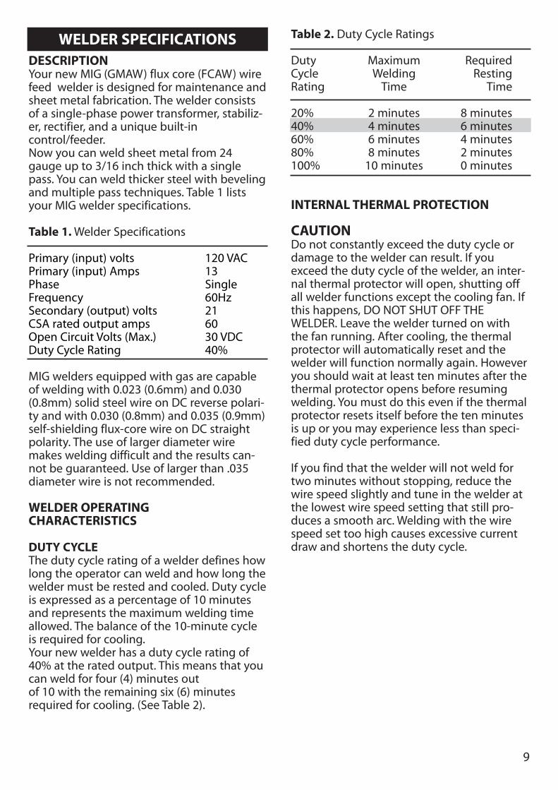
WELDER SPECIFICATIONSDESCRIPTIONYour new MIG (GMAW) flux core (FCAW) wirefeed welder is designed for maintenance andsheet metal fabrication. The welder consistsof a single-phase power transformer, stabiliz-er, rectifier, and a unique built-incontrol/feeder. Now you can weld sheet metal from 24gauge up to 3/16 inch thick with a singlepass. You can weld thicker steel with bevelingand multiple pass techniques. Table 1 listsyour MIG welder specifications.
Table 1. Welder Specifications
Primary (input) volts 120 VACPrimary (input) Amps 13Phase SingleFrequency 60HzSecondary (output) volts 21CSA rated output amps 60Open Circuit Volts (Max.) 30 VDCDuty Cycle Rating 40%
MIG welders equipped with gas are capableof welding with 0.023 (0.6mm) and 0.030(0.8mm) solid steel wire on DC reverse polari-ty and with 0.030 (0.8mm) and 0.035 (0.9mm)self-shielding flux-core wire on DC straightpolarity. The use of larger diameter wiremakes welding difficult and the results can-not be guaranteed. Use of larger than .035diameter wire is not recommended.
WELDER OPERATINGCHARACTERISTICS
DUTY CYCLEThe duty cycle rating of a welder defines howlong the operator can weld and how long thewelder must be rested and cooled. Duty cycleis expressed as a percentage of 10 minutesand represents the maximum welding timeallowed. The balance of the 10-minute cycleis required for cooling.Your new welder has a duty cycle rating of40% at the rated output. This means that youcan weld for four (4) minutes outof 10 with the remaining six (6) minutes required for cooling. (See Table 2).
Table 2. Duty Cycle Ratings
Duty Maximum RequiredCycle Welding RestingRating Time Time
20% 2 minutes 8 minutes40% 4 minutes 6 minutes60% 6 minutes 4 minutes80% 8 minutes 2 minutes100% 10 minutes 0 minutes
INTERNAL THERMAL PROTECTION
CAUTIONDo not constantly exceed the duty cycle ordamage to the welder can result. If youexceed the duty cycle of the welder, an inter-nal thermal protector will open, shutting offall welder functions except the cooling fan. Ifthis happens, DO NOT SHUT OFF THEWELDER. Leave the welder turned on withthe fan running. After cooling, the thermalprotector will automatically reset and thewelder will function normally again. Howeveryou should wait at least ten minutes after thethermal protector opens before resumingwelding. You must do this even if the thermalprotector resets itself before the ten minutesis up or you may experience less than speci-fied duty cycle performance.
If you find that the welder will not weld fortwo minutes without stopping, reduce thewire speed slightly and tune in the welder atthe lowest wire speed setting that still pro-duces a smooth arc. Welding with the wirespeed set too high causes excessive currentdraw and shortens the duty cycle.
10
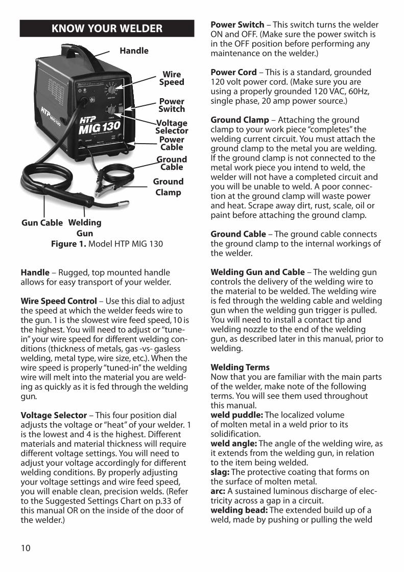
KNOW YOUR WELDER
Handle – Rugged, top mounted handleallows for easy transport of your welder.
Wire Speed Control – Use this dial to adjustthe speed at which the welder feeds wire tothe gun. 1 is the slowest wire feed speed, 10 isthe highest. You will need to adjust or “tune-in” your wire speed for different welding con-ditions (thickness of metals, gas -vs- gaslesswelding, metal type, wire size, etc.). When thewire speed is properly “tuned-in” the weldingwire will melt into the material you are weld-ing as quickly as it is fed through the weldinggun.
Voltage Selector – This four position dialadjusts the voltage or “heat” of your welder. 1is the lowest and 4 is the highest. Differentmaterials and material thickness will requiredifferent voltage settings. You will need toadjust your voltage accordingly for differentwelding conditions. By properly adjustingyour voltage settings and wire feed speed,you will enable clean, precision welds. (Referto the Suggested Settings Chart on p.33 ofthis manual OR on the inside of the door ofthe welder.)
Power Switch – This switch turns the welderON and OFF. (Make sure the power switch isin the OFF position before performing anymaintenance on the welder.)
Power Cord – This is a standard, grounded120 volt power cord. (Make sure you areusing a properly grounded 120 VAC, 60Hz,single phase, 20 amp power source.)
Ground Clamp – Attaching the groundclamp to your work piece “completes” thewelding current circuit. You must attach theground clamp to the metal you are welding.If the ground clamp is not connected to themetal work piece you intend to weld, thewelder will not have a completed circuit andyou will be unable to weld. A poor connec-tion at the ground clamp will waste powerand heat. Scrape away dirt, rust, scale, oil orpaint before attaching the ground clamp.
Ground Cable – The ground cable connectsthe ground clamp to the internal workings ofthe welder.
Welding Gun and Cable – The welding guncontrols the delivery of the welding wire tothe material to be welded. The welding wireis fed through the welding cable and weldinggun when the welding gun trigger is pulled.You will need to install a contact tip andwelding nozzle to the end of the weldinggun, as described later in this manual, prior towelding.
Welding TermsNow that you are familiar with the main partsof the welder, make note of the followingterms. You will see them used throughoutthis manual.weld puddle: The localized volume of molten metal in a weld prior to its solidification.weld angle: The angle of the welding wire, asit extends from the welding gun, in relationto the item being welded.slag: The protective coating that forms onthe surface of molten metal.arc: A sustained luminous discharge of elec-tricity across a gap in a circuit.welding bead: The extended build up of aweld, made by pushing or pulling the weld
Figure 1. Model HTP MIG 130
WeldingGun
GroundClamp
PowerCable
GroundCable
VoltageSelector
PowerSwitch
WireSpeed
Gun Cable
Handle
11
puddle.
POWER SOURCE CONNECTION
POWER REQUIREMENTSThis welder is designed to operate on a proper-ly grounded 120 volt, 60Hz, single-phase alter-nating current (AC) power source fused with a20 amp time delayed fuse or circuit breaker. It isrecommended that a qualified electrician verifythe ACTUAL VOLTAGE at the receptacle intowhich the welder will be plugged and confirmthat the receptacle is properly fused andgrounded. The use of the proper circuit size caneliminate nuisance circuit breaker trippingwhen welding.
DO NOT OPERATE THIS WELDER if the ACTU-AL power source voltage is less than 105 voltsAC or greater than 132 volts AC. Contact a quali-fied electrician if this problem exists. Improperperformance and/or damage to the welder willresult if operated on inadequate or excessivepower.
CONNECT TO POWER SOURCE
WARNING
High voltage danger from power source!Consult a qualified electrician for proper installa-tion of receptacle at the power source. This welder must be grounded while in use toprotect the operator from electrical shock. If youare not sure if your outlet is properly grounded,have it checked by a qualified electrician. Do notcut off the grounding prong or alter the plug inany way and do not use any adapters betweenthe welder’s power cord and the power sourcereceptacle. Make sure the POWER switch is OFFthen connect your welder’s power cord to aproperly grounded 120VAC, 60Hz, single phase,20amp powe source.
EXTENSION CORDSFor optimum welder performance, an extensioncord should not be used unless absolutely nec-essary. If necessary, care must be taken in select-ing an extension cord appropriate for use withyour specific welder. Select a properly grounded extension cord thatwill mate directly with the power source recep-
tacle and the welder power cord without theuse of adapters. Make certain that the extensionis properly wired and in good electrical condi-tion. Extension cords must be a #12 gauge cordat the smallest. Do not use an extension cordover 25 ft. in length.
ASSEMBLING THE WELDERThe following procedures describe the processrequired to assemble, install, maintain, and pre-pare to weld with your new wire feed welder.
UNPACKING THE WELDER1. Remove any cartons or bags containing
parts/accessories. (Most parts are shippedINSIDE the welder door.)
2. Open the cartons or bags packed withyour welder and inspect their contents fordamage.
3. Layout the parts and compare them to thethe packing list in Table 3 to familiarize your-self with the parts and what they are called.This will help you when reading the manual.
PACKING LISTTable 3 contains a list of the items you willfind packed in the carton.
Table 3. Packing List
ITEM QTY.Welder 1Welder Handle 1Handle Screws 2Front and Back Feet 1 ea.Feet Screws 4Parts Bag 1Set Screw 1Contact Tip .023-.030-.035 1 ea.Nozzle 1Wire .035 Fluxcore 1/2 lb.Manual, Instruction 1
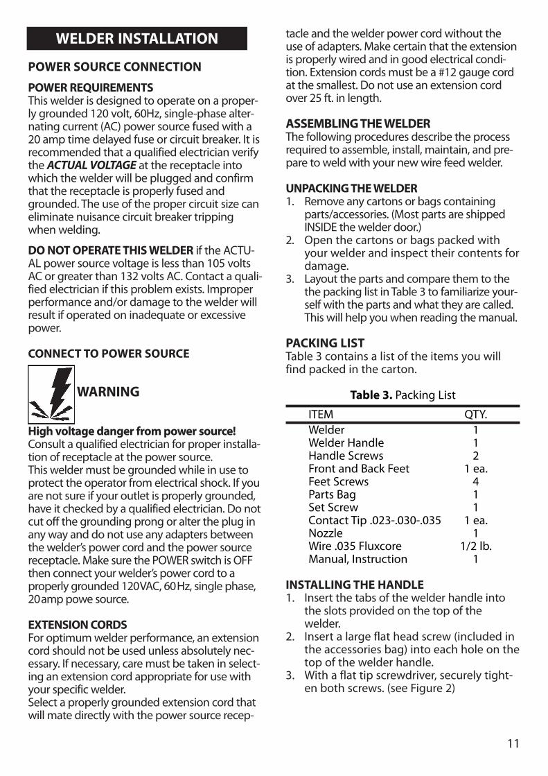
INSTALLING THE HANDLE1. Insert the tabs of the welder handle into
the slots provided on the top of thewelder.
2. Insert a large flat head screw (included inthe accessories bag) into each hole on thetop of the welder handle.
3. With a flat tip screwdriver, securely tight-en both screws. (see Figure 2)
WELDER INSTALLATION
12
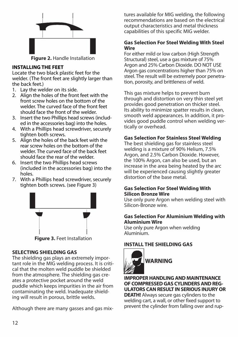
INSTALLING THE FEETLocate the two black plastic feet for thewelder. (The front feet are slightly larger thanthe back feet.)1. Lay the welder on its side.2. Align the holes of the front feet with the
front screw holes on the bottom of thewelder. The curved face of the front feetshould face the front of the welder.
3. Insert the two Phillips head screws (includ-ed in the accessories bag) into the holes.
4. With a Phillips head screwdriver, securelytighten both screws.
5. Align the holes of the back feet with therear screw holes on the bottom of thewelder. The curved face of the back feetshould face the rear of the welder.
6. Insert the two Phillips head screws(included in the accessories bag) into theholes.
7. With a Phillips head screwdriver, securelytighten both screws. (see Figure 3)
SELECTING SHIELDING GASThe shielding gas plays an extremely impor-tant role in the MIG welding process. It is criti-cal that the molten weld puddle be shieldedfrom the atmosphere. The shielding gas cre-ates a protective pocket around the weldpuddle which keeps impurities in the air fromcontaminating the weld. Inadequate shield-ing will result in porous, brittle welds.
Although there are many gasses and gas mix-
tures available for MIG welding, the followingrecommendations are based on the electricaloutput characteristics and metal thicknesscapabilities of this specific MIG welder.
Gas Selection For Steel Welding With SteelWire For either mild or low carbon (High StrengthStructural) steel, use a gas mixture of 75%Argon and 25% Carbon Dioxide. DO NOT USEArgon gas concentrations higher than 75% onsteel. The result will be extremely poor penetra-tion, porosity, and brittleness of weld.
This gas mixture helps to prevent burnthrough and distortion on very thin steel yetprovides good penetration on thicker steel.Its ability to minimize spatter results in clean,smooth weld appearances. In addition, it pro-vides good puddle control when welding ver-tically or overhead.
Gas Selection For Stainless Steel WeldingThe best shielding gas for stainless steelwelding is a mixture of 90% Helium, 7.5%Argon, and 2.5% Carbon Dioxide. However,the 100% Argon, can also be used, but anincrease in the area being heated by the arcwill be experienced causing slightly greaterdistortion of the base metal.
Gas Selection For Steel Welding WithSilicon Bronze WireUse only pure Argon when welding steel withSilicon-Bronze wire.
Gas Selection For Aluminium Welding withAluminium WireUse only pure Argon when weldingAluminium.
INSTALL THE SHIELDING GAS
WARNING
IMPROPER HANDLING AND MAINTENANCEOF COMPRESSED GAS CYLINDERS AND REG-ULATORS CAN RESULT IN SERIOUS INJURY ORDEATH! Always secure gas cylinders to thewelding cart, a wall, or other fixed support toprevent the cylinder from falling over and rup-
Figure 3. Feet Installation
Figure 2. Handle Installation
13
turing. Read, understand, and follow all theCOMPRESSED GASSES AND EQUIPMENT HAZ-ARDS in the SAFETY SUMMARY at the front ofthis manual. Secure your gas cylinder to thewelding cart, or other fixed support.1. Remove the protective cap from the cylin-
der and inspect the regulator connectingthreads for dust, dirt, oil, and grease.Remove any dust or dirt with a cleancloth. DO NOT ATTACH YOUR REGULATORIF OIL, GREASE, OR DAMAGE ARE PRE-SENT.
2. Open the cylinder valve FOR JUST ANINSTANT to blow out any foreign matterinside the valve port. Never aim the openvalve cylinder port at yourself orbystanders.
3. Screw the regulator into the cylindervalve and tighten with a wrench.
4. Firmly push the gas hose over barbed fit-tings on back of welder and regulator.
5. Secure both ends of hose onto barbed fit-tings with hose clamps.
CHECK THE GAS FLOW
WARNING
IMPROPER HANDLING AND MAINTENANCEOF COMPRESSED GAS CYLINDERS AND REG-ULATORS CAN RESULT IN SERIOUS INJURYOR DEATH. To reduce the risk of injury ordeath, always stand to the side of the cylinderopposite the regulator when opening thecylinder valve, keeping the cylinder valvebetween you and the regulator. Never aim theopen cylinder valve port at yourself orbystanders. Failure to comply with this warningcould result in serious personal injury.
Note: If the cylinder you have is equipped withmale regulator connecting threads instead offemale, you will need to obtain a special com-pressed gas cylinder adaptor from your gassupplier to install between your gas cylinderand regulator.
-The gas control function does not requirethe welder to be turned on or plugged in.
-To avoid damage to your regulator, makesure you have the regulator valve closedbefore opening the cylinder valve.
1. Slowly crack open the cylinder valve, thenturn open ALL THE WAY.
2. Pull the trigger on the gun to allow the gasto flow. KEEP THE TRIGGER PULLED. Listenand feel for gas flowing from the end of thewelding gun. If your regulator has noadjustment, it has been preset at the facto-ry for a flow of 20 cubic feet per hour. Ifyour gas regulator has an adjustment tocontrol the gas flow rate, turn the adjust-ment key clockwise to increase gas flow;counterclockwise to reduce flow. For mostwelding, the gas flow should be set at 15-20 cubic feet per hour. If no gas is heard orfelt, verify all steps involved in connectingthe gas.
3. Release the trigger.
Note: If welding outside or in a draft, it maybecome necessary to set up a wind break tokeep the shielding gas from being blown fromthe weld area.
-MAKE SURE TO TURN OFF THE GAS CYLIN-DER VALVE WHEN DONE WELDING.
ALIGN AND SET THE DRIVE ROLLERBefore installing any welding wire into the unit,the proper sized groove must be placed intoposition on the wire drive mechanism.
Change the drive roller according to the following steps:1. Remove the drive tension by unscrewing
the tension adjusting screw (ALL THE WAYin a counterclockwise direction). The drivetension screw will come loose, allowing youto pull the drive tension arm up away fromthe drive roller. Make sure to keep thescrew and the spring in place with the drivetension arm.
2. If there is wire already installed in thewelder, roll it back onto the wire spool byhand-turning the spool counter-clockwise.Be careful not to allow the wire to comeout of the rear end of the gun withoutholding onto it or it will unspool itself. Putthe end of the wire into the hole on theoutside edge of the wire spool and bend itover to hold the wire in place. Remove thespool of wire from the welder.
3. Loosen the drive roller set screw with theprovided hex wrench and pull the driveroller off the drive shaft.
14
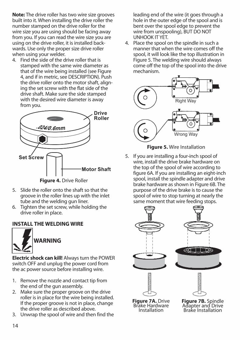
Note: The drive roller has two wire size groovesbuilt into it. When installing the drive roller thenumber stamped on the drive roller for thewire size you are using should be facing awayfrom you. If you can read the wire size you areusing on the drive roller, it is installed back-wards. Use only the proper size drive rollerwhen using your welder.4. Find the side of the drive roller that is
stamped with the same wire diameter asthat of the wire being installed (see Figure4, and if in metric, see DESCRIPTION). Pushthe drive roller onto the motor shaft, align-ing the set screw with the flat side of thedrive shaft. Make sure the side stampedwith the desired wire diameter is awayfrom you.
5. Slide the roller onto the shaft so that thegroove in the roller lines up with the inlettube and the welding gun liner.
6. Tighten the set screw, while holding thedrive roller in place.
INSTALL THE WELDING WIRE
WARNING
Electric shock can kill! Always turn the POWERswitch OFF and unplug the power cord fromthe ac power source before installing wire.
1. Remove the nozzle and contact tip fromthe end of the gun assembly.
2. Make sure the proper groove on the driveroller is in place for the wire being installed.If the proper groove is not in place, changethe drive roller as described above.
3. Unwrap the spool of wire and then find the
leading end of the wire (it goes through ahole in the outer edge of the spool and isbent over the spool edge to prevent thewire from unspooling), BUT DO NOTUNHOOK IT YET.
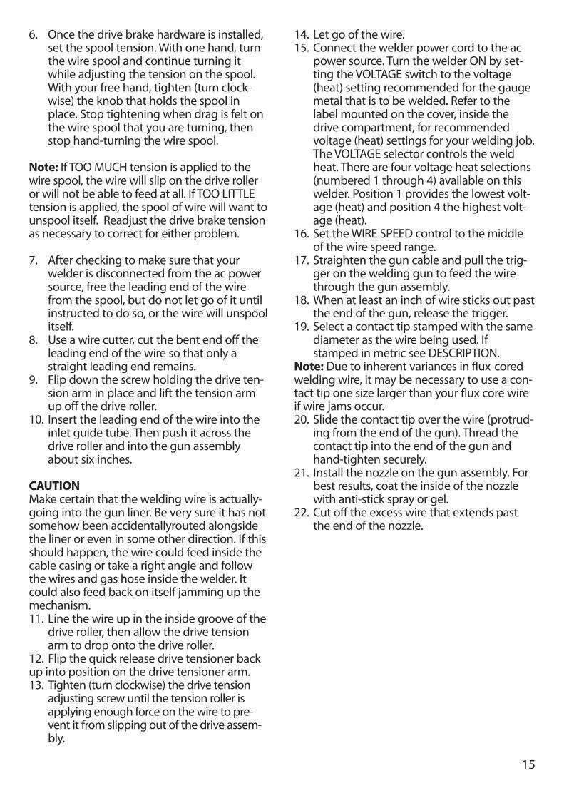
4. Place the spool on the spindle in such amanner that when the wire comes off thespool, it will look like the top illustration inFigure 5. The welding wire should alwayscome off the top of the spool into the drivemechanism.
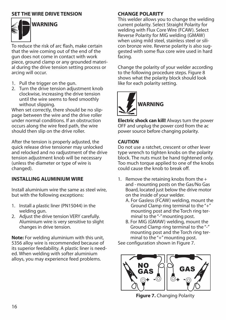
5. If you are installing a four-inch spool ofwire, install the drive brake hardware onthe top of the spool of wire according tofigure 6A. If you are installing an eight-inchspool, install the spindle adapter and drivebrake hardware as shown in Figure 6B. Thepurpose of the drive brake is to cause thespool of wire to stop turning at nearly thesame moment that wire feeding stops.
Figure 4. Drive Roller
Figure 5. Wire Installation
Figure 7A. DriveBrake Hardware
Installation
Figure 7B. SpindleAdapter and DriveBrake Installation
15
6. Once the drive brake hardware is installed,set the spool tension. With one hand, turnthe wire spool and continue turning itwhile adjusting the tension on the spool.With your free hand, tighten (turn clock-wise) the knob that holds the spool inplace. Stop tightening when drag is felt onthe wire spool that you are turning, thenstop hand-turning the wire spool.
Note: If TOO MUCH tension is applied to thewire spool, the wire will slip on the drive rolleror will not be able to feed at all. If TOO LITTLEtension is applied, the spool of wire will want tounspool itself. Readjust the drive brake tensionas necessary to correct for either problem.
7. After checking to make sure that yourwelder is disconnected from the ac powersource, free the leading end of the wirefrom the spool, but do not let go of it untilinstructed to do so, or the wire will unspoolitself.
8. Use a wire cutter, cut the bent end off theleading end of the wire so that only astraight leading end remains.
9. Flip down the screw holding the drive ten-sion arm in place and lift the tension armup off the drive roller.
10. Insert the leading end of the wire into theinlet guide tube. Then push it across thedrive roller and into the gun assemblyabout six inches.
CAUTIONMake certain that the welding wire is actually-going into the gun liner. Be very sure it has notsomehow been accidentallyrouted alongsidethe liner or even in some other direction. If thisshould happen, the wire could feed inside thecable casing or take a right angle and followthe wires and gas hose inside the welder. Itcould also feed back on itself jamming up themechanism.11. Line the wire up in the inside groove of the
drive roller, then allow the drive tensionarm to drop onto the drive roller.
12. Flip the quick release drive tensioner back up into position on the drive tensioner arm.13. Tighten (turn clockwise) the drive tension
adjusting screw until the tension roller isapplying enough force on the wire to pre-vent it from slipping out of the drive assem-bly.
14. Let go of the wire.15. Connect the welder power cord to the ac
power source. Turn the welder ON by set-ting the VOLTAGE switch to the voltage(heat) setting recommended for the gaugemetal that is to be welded. Refer to thelabel mounted on the cover, inside thedrive compartment, for recommendedvoltage (heat) settings for your welding job.The VOLTAGE selector controls the weldheat. There are four voltage heat selections(numbered 1 through 4) available on thiswelder. Position 1 provides the lowest volt-age (heat) and position 4 the highest volt-age (heat).
16. Set the WIRE SPEED control to the middleof the wire speed range.
17. Straighten the gun cable and pull the trig-ger on the welding gun to feed the wirethrough the gun assembly.
18. When at least an inch of wire sticks out pastthe end of the gun, release the trigger.
19. Select a contact tip stamped with the samediameter as the wire being used. Ifstamped in metric see DESCRIPTION.
Note: Due to inherent variances in flux-coredwelding wire, it may be necessary to use a con-tact tip one size larger than your flux core wireif wire jams occur.20. Slide the contact tip over the wire (protrud-
ing from the end of the gun). Thread thecontact tip into the end of the gun andhand-tighten securely.
21. Install the nozzle on the gun assembly. Forbest results, coat the inside of the nozzlewith anti-stick spray or gel.
22. Cut off the excess wire that extends pastthe end of the nozzle.
16
SET THE WIRE DRIVE TENSION
WARNING
To reduce the risk of arc flash, make certainthat the wire coming out of the end of thegun does not come in contact with workpiece, ground clamp or any grounded materi-al during the drive tension setting process orarcing will occur.
1. Pull the trigger on the gun.2. Turn the drive tension adjustment knob
clockwise, increasing the drive tensionuntil the wire seems to feed smoothlywithout slipping.
When set correctly, there should be no slip-page between the wire and the drive rollerunder normal conditions. If an obstructionoccurs along the wire feed path, the wireshould then slip on the drive roller.
After the tension is properly adjusted, thequick release drive tensioner may unlockedand relocked and no radjustment of the drivetension adjustment knob will be necessary(unless the diameter or type of wire ischanged).
INSTALLING ALUMINIUM WIRE
Install aluminium wire the same as steel wire,but with the following exceptions:
1. Install a plastic liner (PN15044) in thewelding gun.
2. Adjust the drive tension VERY carefully. Aluminium wire is very sensitive to slight changes in drive tension.
Note: For welding aluminium with this unit,5356 alloy wire is recommended because ofits superior feedability. A plastic liner is need-ed. When welding with softer aluminiumalloys, you may experience feed problems.
CHANGE POLARITYThis welder allows you to change the weldingcurrent polarity. Select Straight Polarity forwelding with Flux Core Wire (FCAW). SelectReverse Polarity for MIG welding (GMAW)when using mild steel, stainless steel or sili-con bronze wire. Reverse polarity is also sug-gested with some flux core wire used in hardfacing.
Change the polarity of your welder accordingto the following procedure steps. Figure 8shows what the polarity block should looklike for each polarity setting.
WARNING
Electric shock can kill! Always turn the powerOFF and unplug the power cord from the acpower source before changing polarity.
CAUTIONDo not use a ratchet, crescent or other levertype wrench to tighten knobs on the polarityblock. The nuts must be hand tightened only.Too much torque applied to one of the knobscould cause the knob to break off.
1. Remove the retaining knobs from the +and - mounting posts on the Gas/No GasBoard, located just below the drive motoron the inside of your welder.A. For Gasless (FCAW) welding, mount the
Ground Clamp ring terminal to the “+”mounting post and the Torch ring ter-minal to the “-”mounting post.
B. For MIG (GMAW) welding, mount theGround Clamp ring terminal to the “-”mounting post and the Torch ring ter-minal to the “+” mounting post.
See configuration shown in Figure 7.
Figure 7. Changing Polarity
17
2. Attach the ground clamp to the workpiece, making sure that it is cleaned ofdirt, oil, rust, scale, oxidation, and paint atthe point of connection.
Note: It is best to connect the ground clampdirectly to the work piece and as close to theweld as possible. If it is impractical to connectthe ground clamp directly to the work piece,connect it to the metal that is securelyattached to the work piece, but not electrical-ly insulated from it. Make certain this othermetal is of equal or greater thickness thanthat of the workpiece.
CAUTION
Risk of electric component damage! If theground clamp is being connected to an auto-mobile or other equipment with on-boardcomputer systems, solid state electronic con-trols, solid state sound systems, etc., do notweld until disconnecting the battery that isattached to the chassis ground. Failure to doso may result in electronic component dam-age.
18
Operation of this welder consists of selectingand adjusting operating controls for opti-mum voltage (welding heat) and wire speedsettings.
CONTROLS AND INDICATORS
POWER SWITCH - The power switch supplieselectrical current to the welder. ALWAYS turnthe power switch to the OFF position andunplug the welder before performing anymaintenance.
VOLTAGE SELECTOR - The voltage selectorcontrols the welding heat. The voltage selec-tor is numbered 1-4. Number 1 is the lowestheat and number 4 is the highest. Refer tothe label under the welder hood (or on page33 of this manual) for recommended heatsettings for your welding job.
WIRE SPEED CONTROL - The wire speed con-trol adjusts the speed at which the wire is fedout of the welding gun. The wire speed needsto be closely matched (tuned-in) to the rateat which it is being melted off. Some thingsthat affect wire speed selection are the typeand diameter of the wire being used, the heatsetting selected, and the welding position tobe used.
Note: The wire will feed faster without an arc.When an arc is being drawn, the wire speedwill slow down.
TUNING IN THE WIRE SPEEDThis is one of the most important parts ofMIG welder operation and must be donebefore starting each welding job or wheneverany of the following variables are changed:heat setting wire diameter, or wire type.
1. Set up and ground a scrap piece of thesame type of material which you will bewelding. It should be equal to or greaterthat the thickness of the actual work piece,and free of oil, paint, rust, etc.
2. Select a heat setting.
3. Hold the gun in one hand, allowing thenozzle to rest on the edge of the workpiecefarthest away from you, and at an anglesimilar to that which will be used whenwelding. (SEE HOLDING THE GUN on page19 if you are uncertain of the angle atwhich you will be welding)
4. With your free hand, turn the Wire SpeedDial to maximum and continue to holdonto the knob.
WARNING
EXPOSURE TO A WELDING ARC ISEXTREMELY HARMFUL TO THE EYES ANDSKIN! Prolonged exposure to the welding arccan cause blindness and burns. Never strikean arc or being welding until you are ade-quately protected. Wear flameproof weldinggloves, a heavy long sleeved shirt, cufflesstrousers, high topped shoes and a weldinghelmet.
5. Lower your welding helmet and pull thetrigger on the gun to start an arc, thenbegin to drag the gun towards you whilesimultaneously turning the Wire Speed Dialcounter-clockwise.
6. LISTEN! As you decrease the wire speed,the sound that the arc makes will changefrom a sputtering to a high-pitchedbuzzing sound and then will begin sputter-ing again if you decrease the wire speedtoo much. The wire speed that creates asmooth high-pitched buzzing sound willachieve the best quality weld.
You can use the wire speed control to slightlyincrease or decrease the heat and penetrationfor a given heat setting by selecting hugher orlower wire speed settings. Repeat this tune-inprocedure if you select a new heat setting, adifferent diameter wire, or a different type ofwelding wire.
LEARNING TO WELDMIG (Metal Inert Gas) welding is the processof uniting metallic parts by heating andallowing the metals to flow together throughthe use of an electrical arc. The electrical arcis created between a continuous consumable
OPERATION
19
wire electrode (the welding wire) and thework piece. An inert shielding gas is used toprotect the weld puddle from contaminationand enhance the welding capabilities of theelectrical arc.
Whether you have welded before or not, it isimportant that you become familiar with yournew welder, its controls, and the resultsachieved at different settings. We strongly rec-ommend that you practice with your newwelder on scrap metal trying different heatsettings, base metal thicknesses, and weldingpositions for each type and size of wire youwill be using. By doing this you will gain a feelfor how changes in these welding variablesaffect the weld.
Of course, if you have not welded before, youwill need to develop welding skills and tech-niques as well.
The self-taught welder learns through aprocess of trial and error. The best way toteach yourself how to weld is with short peri-ods of practice at regular intervals. All prac-tice welds should be done on scrap metalthat can be discarded. Do not attempt tomake any repairs on valuable equipmentuntil you have satisfied yourself that yourpractice welds are of good appearance andfree of slag or gas inclusions. What you fail tolearn through practice will be learnedthrough mistakes and re-welds later on.
HOLDING THE GUNThe best way to hold the welding gun is theway that feels most comfortable to you. Whilepracticing to use your new welder, experi-ment holding the gun in different positionsuntil you find the one that seems to workbest for you. Refer to WELDING POSITIONS -p.21.
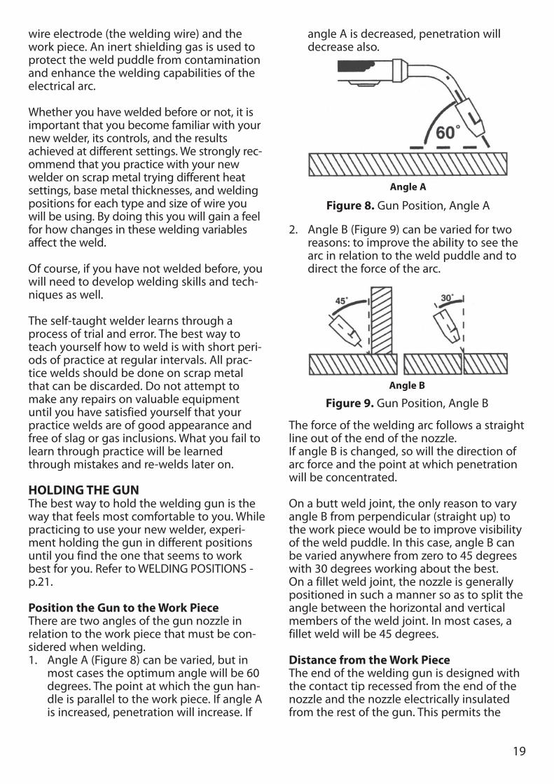
Position the Gun to the Work PieceThere are two angles of the gun nozzle inrelation to the work piece that must be con-sidered when welding.1. Angle A (Figure 8) can be varied, but in
most cases the optimum angle will be 60degrees. The point at which the gun han-dle is parallel to the work piece. If angle Ais increased, penetration will increase. If
angle A is decreased, penetration willdecrease also.
2. Angle B (Figure 9) can be varied for tworeasons: to improve the ability to see thearc in relation to the weld puddle and todirect the force of the arc.
The force of the welding arc follows a straightline out of the end of the nozzle. If angle B is changed, so will the direction ofarc force and the point at which penetrationwill be concentrated.
On a butt weld joint, the only reason to varyangle B from perpendicular (straight up) tothe work piece would be to improve visibilityof the weld puddle. In this case, angle B canbe varied anywhere from zero to 45 degreeswith 30 degrees working about the best.On a fillet weld joint, the nozzle is generallypositioned in such a manner so as to split theangle between the horizontal and verticalmembers of the weld joint. In most cases, afillet weld will be 45 degrees.
Distance from the Work PieceThe end of the welding gun is designed withthe contact tip recessed from the end of thenozzle and the nozzle electrically insulatedfrom the rest of the gun. This permits the
Angle A
Figure 8. Gun Position, Angle A
Angle B
Figure 9. Gun Position, Angle B
20
operator to actually rest the nozzle on thework piece and drag it along while welding.This can be very helpful to beginning weldersto steady the gun, allowing the welder toconcentrate on welding technique. If the noz-zle is held off the work piece, the distancebetween the nozzle and the work pieceshould be kept constant and should notexceed 1/4 inch or the arc may begin sputter-ing, signaling a loss in welding performance
WELDING TECHNIQUES
WARNING
EXPOSURE TO A WELDING ARC ISEXTREMELY HARMFUL TO THE EYES ANDSKIN! Prolonged exposure to the welding arccan cause blindness and burns. Never strikean arc or begin welding until you are ade-quately protected. Wear flameproof weldinggloves, a heavy long sleeved shirt, cufflesstrousers, high topped shoes and a weldinghelmet.
WARNING
ELECTRIC SHOCK CAN KILL! To preventELECTRIC SHOCK, do not perform any weld-ing while standing, kneeling, or lying directlyon the grounded work.
MOVING THE GUNGun travel refers to the movement of the gunalong the weld joint and is broken into twoelements: Direction and Speed. A solid weldbead requires that the welding gun bemoved steadily and at the right speed alongthe weld joint. Moving the gun too fast, tooslow, or erratically will prevent proper fusionor create a lumpy, uneven bead.
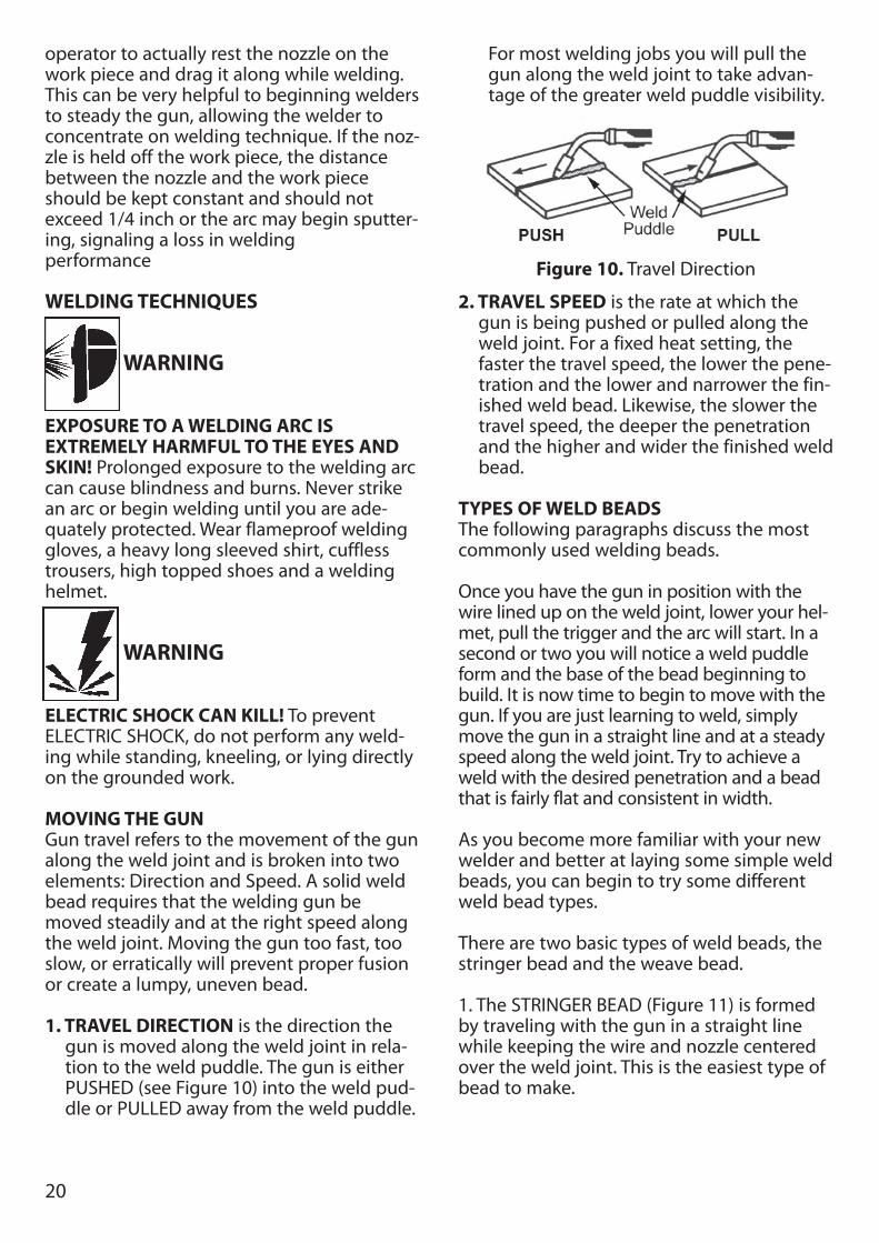
1. TRAVEL DIRECTION is the direction thegun is moved along the weld joint in rela-tion to the weld puddle. The gun is eitherPUSHED (see Figure 10) into the weld pud-dle or PULLED away from the weld puddle.
For most welding jobs you will pull thegun along the weld joint to take advan-tage of the greater weld puddle visibility.
2. TRAVEL SPEED is the rate at which thegun is being pushed or pulled along theweld joint. For a fixed heat setting, thefaster the travel speed, the lower the pene-tration and the lower and narrower the fin-ished weld bead. Likewise, the slower thetravel speed, the deeper the penetrationand the higher and wider the finished weldbead.
TYPES OF WELD BEADSThe following paragraphs discuss the mostcommonly used welding beads.
Once you have the gun in position with thewire lined up on the weld joint, lower your hel-met, pull the trigger and the arc will start. In asecond or two you will notice a weld puddleform and the base of the bead beginning tobuild. It is now time to begin to move with thegun. If you are just learning to weld, simplymove the gun in a straight line and at a steadyspeed along the weld joint. Try to achieve aweld with the desired penetration and a beadthat is fairly flat and consistent in width.
As you become more familiar with your newwelder and better at laying some simple weldbeads, you can begin to try some differentweld bead types.
There are two basic types of weld beads, thestringer bead and the weave bead.
1. The STRINGER BEAD (Figure 11) is formedby traveling with the gun in a straight linewhile keeping the wire and nozzle centeredover the weld joint. This is the easiest type ofbead to make.
Figure 10. Travel Direction
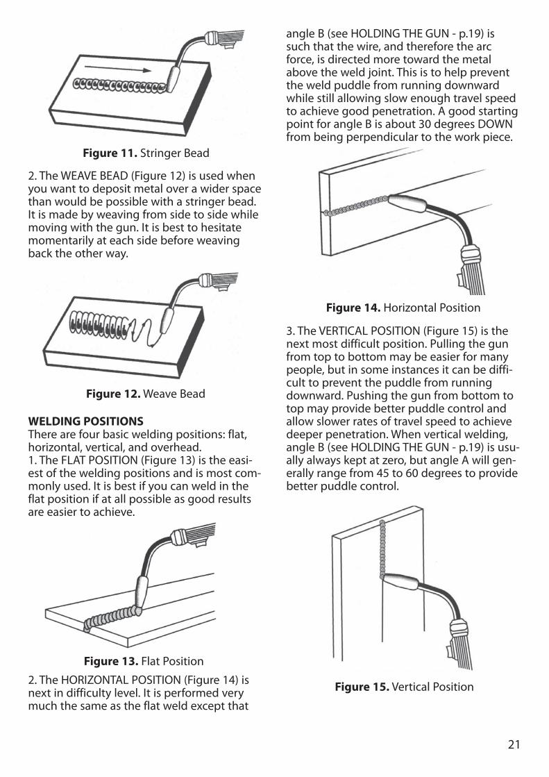
2. The WEAVE BEAD (Figure 12) is used whenyou want to deposit metal over a wider spacethan would be possible with a stringer bead.It is made by weaving from side to side whilemoving with the gun. It is best to hesitatemomentarily at each side before weavingback the other way.
WELDING POSITIONSThere are four basic welding positions: flat,horizontal, vertical, and overhead.1. The FLAT POSITION (Figure 13) is the easi-est of the welding positions and is most com-monly used. It is best if you can weld in theflat position if at all possible as good resultsare easier to achieve.
2. The HORIZONTAL POSITION (Figure 14) isnext in difficulty level. It is performed verymuch the same as the flat weld except that
angle B (see HOLDING THE GUN - p.19) issuch that the wire, and therefore the arcforce, is directed more toward the metalabove the weld joint. This is to help preventthe weld puddle from running downwardwhile still allowing slow enough travel speedto achieve good penetration. A good startingpoint for angle B is about 30 degrees DOWNfrom being perpendicular to the work piece.
3. The VERTICAL POSITION (Figure 15) is thenext most difficult position. Pulling the gunfrom top to bottom may be easier for manypeople, but in some instances it can be diffi-cult to prevent the puddle from runningdownward. Pushing the gun from bottom totop may provide better puddle control andallow slower rates of travel speed to achievedeeper penetration. When vertical welding,angle B (see HOLDING THE GUN - p.19) is usu-ally always kept at zero, but angle A will gen-erally range from 45 to 60 degrees to providebetter puddle control.
Figure 13. Flat Position
Figure 11. Stringer Bead
Figure 12. Weave Bead
21
Figure 15. Vertical Position
Figure 14. Horizontal Position
WARNING
Hot slag can cause fires and serious injuryfrom burns! Be sure to wear protective cloth-ing and eye gear when using the OverheadPosition.
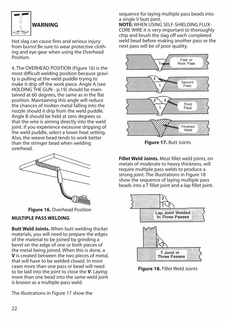
4. The OVERHEAD POSITION (Figure 16) is themost difficult welding position because gravi-ty is pulling at the weld puddle trying tomake it drip off the work piece. Angle A (seeHOLDING THE GUN - p.19) should be main-tained at 60 degrees, the same as in the flatposition. Maintaining this angle will reducethe chances of molten metal falling into thenozzle should it drip from the weld puddle.Angle B should be held at zero degrees sothat the wire is aiming directly into the weldjoint. If you experience excessive dripping ofthe weld puddle, select a lower heat setting.Also, the weave bead tends to work betterthan the stringer bead when welding overhead.
MULTIPLE PASS WELDING
Butt Weld Joints. When butt welding thickermaterials, you will need to prepare the edgesof the material to be joined by grinding abevel on the edge of one or both pieces ofthe metal being joined. When this is done, aV is created between the two pieces of metal,that will have to be welded closed. In mostcases more than one pass or bead will needto be laid into the joint to close the V. Layingmore than one bead into the same weld jointis known as a multiple-pass weld.
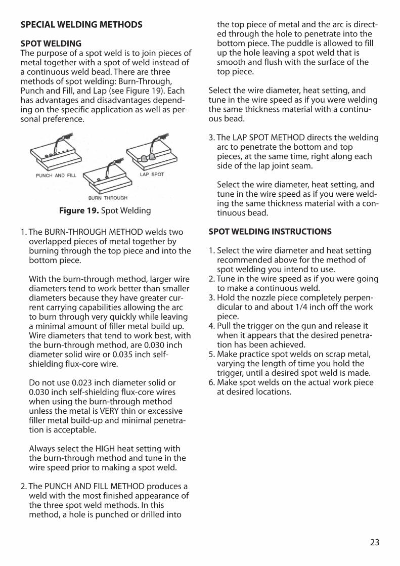
The illustrations in Figure 17 show the
sequence for laying multiple pass beads intoa single V butt joint.NOTE: WHEN USING SELF-SHIELDING FLUX-CORE WIRE it is very important to thoroughlychip and brush the slag off each completedweld bead before making another pass or thenext pass will be of poor quality.
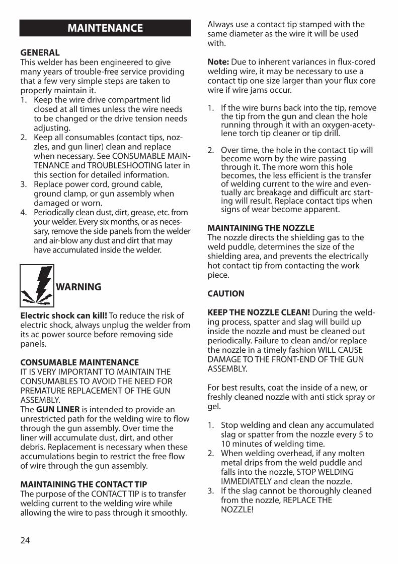
Fillet Weld Joints. Most fillet weld joints, onmetals of moderate to heavy thickness, willrequire multiple pass welds to produce astrong joint. The illustrations in Figure 18show the sequence of laying multiple passbeads into a T fillet joint and a lap fillet joint.
Figure 16. Overhead Position
22
Figure 17. Butt Joints
Figure 18. Fillet Weld Joints
23
SPECIAL WELDING METHODS
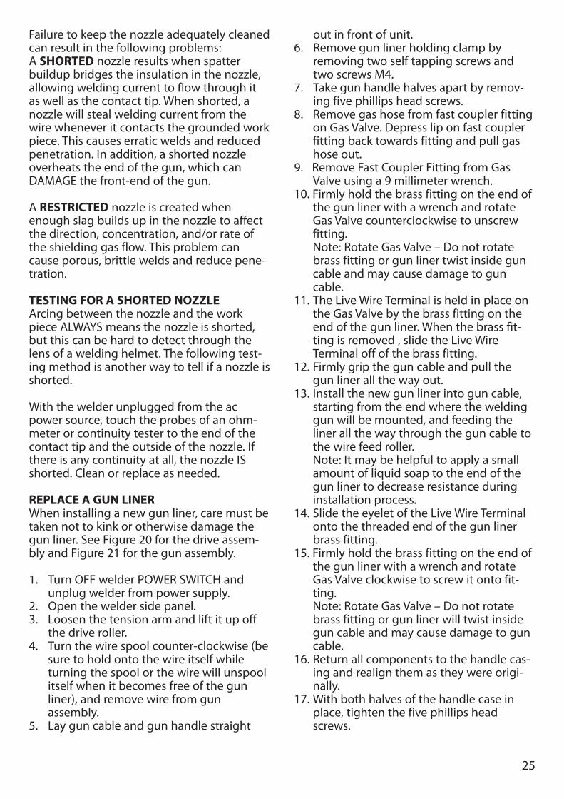
SPOT WELDINGThe purpose of a spot weld is to join pieces ofmetal together with a spot of weld instead ofa continuous weld bead. There are threemethods of spot welding: Burn-Through,Punch and Fill, and Lap (see Figure 19). Eachhas advantages and disadvantages depend-ing on the specific application as well as per-sonal preference.
1. The BURN-THROUGH METHOD welds twooverlapped pieces of metal together byburning through the top piece and into thebottom piece.
With the burn-through method, larger wirediameters tend to work better than smallerdiameters because they have greater cur-rent carrying capabilities allowing the arcto burn through very quickly while leavinga minimal amount of filler metal build up.Wire diameters that tend to work best, withthe burn-through method, are 0.030 inchdiameter solid wire or 0.035 inch self-shielding flux-core wire.
Do not use 0.023 inch diameter solid or0.030 inch self-shielding flux-core wireswhen using the burn-through method unless the metal is VERY thin or excessivefiller metal build-up and minimal penetra-tion is acceptable.
Always select the HIGH heat setting withthe burn-through method and tune in thewire speed prior to making a spot weld.
2. The PUNCH AND FILL METHOD produces aweld with the most finished appearance ofthe three spot weld methods. In thismethod, a hole is punched or drilled into
the top piece of metal and the arc is direct-ed through the hole to penetrate into thebottom piece. The puddle is allowed to fillup the hole leaving a spot weld that issmooth and flush with the surface of thetop piece.
Select the wire diameter, heat setting, andtune in the wire speed as if you were weldingthe same thickness material with a continu-ous bead.
3. The LAP SPOT METHOD directs the weldingarc to penetrate the bottom and toppieces, at the same time, right along eachside of the lap joint seam.
Select the wire diameter, heat setting, andtune in the wire speed as if you were weld-ing the same thickness material with a con-tinuous bead.
SPOT WELDING INSTRUCTIONS
1. Select the wire diameter and heat settingrecommended above for the method ofspot welding you intend to use.
2. Tune in the wire speed as if you were goingto make a continuous weld.
3. Hold the nozzle piece completely perpen-dicular to and about 1/4 inch off the workpiece.
4. Pull the trigger on the gun and release itwhen it appears that the desired penetra-tion has been achieved.
5. Make practice spot welds on scrap metal,varying the length of time you hold thetrigger, until a desired spot weld is made.
6. Make spot welds on the actual work pieceat desired locations.
Figure 19. Spot Welding
24
GENERALThis welder has been engineered to givemany years of trouble-free service providingthat a few very simple steps are taken toproperly maintain it.1. Keep the wire drive compartment lid
closed at all times unless the wire needsto be changed or the drive tension needsadjusting.
2. Keep all consumables (contact tips, noz-zles, and gun liner) clean and replacewhen necessary. See CONSUMABLE MAIN-TENANCE and TROUBLESHOOTING later inthis section for detailed information.
3. Replace power cord, ground cable,ground clamp, or gun assembly whendamaged or worn.
4. Periodically clean dust, dirt, grease, etc. fromyour welder. Every six months, or as neces-sary, remove the side panels from the welderand air-blow any dust and dirt that mayhave accumulated inside the welder.
WARNING
Electric shock can kill! To reduce the risk ofelectric shock, always unplug the welder fromits ac power source before removing sidepanels.
CONSUMABLE MAINTENANCEIT IS VERY IMPORTANT TO MAINTAIN THECONSUMABLES TO AVOID THE NEED FORPREMATURE REPLACEMENT OF THE GUNASSEMBLY.The GUN LINER is intended to provide anunrestricted path for the welding wire to flowthrough the gun assembly. Over time theliner will accumulate dust, dirt, and otherdebris. Replacement is necessary when theseaccumulations begin to restrict the free flowof wire through the gun assembly.
MAINTAINING THE CONTACT TIPThe purpose of the CONTACT TIP is to transferwelding current to the welding wire whileallowing the wire to pass through it smoothly.
Always use a contact tip stamped with thesame diameter as the wire it will be usedwith.
Note: Due to inherent variances in flux-coredwelding wire, it may be necessary to use acontact tip one size larger than your flux corewire if wire jams occur.
1. If the wire burns back into the tip, removethe tip from the gun and clean the holerunning through it with an oxygen-acety-lene torch tip cleaner or tip drill.
2. Over time, the hole in the contact tip willbecome worn by the wire passingthrough it. The more worn this holebecomes, the less efficient is the transferof welding current to the wire and even-tually arc breakage and difficult arc start-ing will result. Replace contact tips whensigns of wear become apparent.
MAINTAINING THE NOZZLEThe nozzle directs the shielding gas to theweld puddle, determines the size of theshielding area, and prevents the electricallyhot contact tip from contacting the workpiece.
CAUTION
KEEP THE NOZZLE CLEAN! During the weld-ing process, spatter and slag will build upinside the nozzle and must be cleaned outperiodically. Failure to clean and/or replacethe nozzle in a timely fashion WILL CAUSEDAMAGE TO THE FRONT-END OF THE GUNASSEMBLY.
For best results, coat the inside of a new, orfreshly cleaned nozzle with anti stick spray orgel.
1. Stop welding and clean any accumulatedslag or spatter from the nozzle every 5 to10 minutes of welding time.
2. When welding overhead, if any moltenmetal drips from the weld puddle andfalls into the nozzle, STOP WELDINGIMMEDIATELY and clean the nozzle.
3. If the slag cannot be thoroughly cleanedfrom the nozzle, REPLACE THE NOZZLE!
MAINTENANCE
25
Failure to keep the nozzle adequately cleanedcan result in the following problems:A SHORTED nozzle results when spatterbuildup bridges the insulation in the nozzle,allowing welding current to flow through itas well as the contact tip. When shorted, anozzle will steal welding current from thewire whenever it contacts the grounded workpiece. This causes erratic welds and reducedpenetration. In addition, a shorted nozzleoverheats the end of the gun, which canDAMAGE the front-end of the gun.
A RESTRICTED nozzle is created whenenough slag builds up in the nozzle to affectthe direction, concentration, and/or rate ofthe shielding gas flow. This problem cancause porous, brittle welds and reduce pene-tration.
TESTING FOR A SHORTED NOZZLEArcing between the nozzle and the workpiece ALWAYS means the nozzle is shorted,but this can be hard to detect through thelens of a welding helmet. The following test-ing method is another way to tell if a nozzle isshorted.
With the welder unplugged from the acpower source, touch the probes of an ohm-meter or continuity tester to the end of thecontact tip and the outside of the nozzle. Ifthere is any continuity at all, the nozzle ISshorted. Clean or replace as needed.
REPLACE A GUN LINERWhen installing a new gun liner, care must betaken not to kink or otherwise damage thegun liner. See Figure 20 for the drive assem-bly and Figure 21 for the gun assembly.
1. Turn OFF welder POWER SWITCH andunplug welder from power supply.
2. Open the welder side panel.3. Loosen the tension arm and lift it up off
the drive roller.4. Turn the wire spool counter-clockwise (be
sure to hold onto the wire itself whileturning the spool or the wire will unspoolitself when it becomes free of the gunliner), and remove wire from gun assembly.
5. Lay gun cable and gun handle straight
out in front of unit.6. Remove gun liner holding clamp by
removing two self tapping screws andtwo screws M4.
7. Take gun handle halves apart by remov-ing five phillips head screws.
8. Remove gas hose from fast coupler fittingon Gas Valve. Depress lip on fast couplerfitting back towards fitting and pull gashose out.
9. Remove Fast Coupler Fitting from GasValve using a 9 millimeter wrench.
10. Firmly hold the brass fitting on the end ofthe gun liner with a wrench and rotateGas Valve counterclockwise to unscrewfitting.Note: Rotate Gas Valve – Do not rotatebrass fitting or gun liner twist inside guncable and may cause damage to guncable.
11. The Live Wire Terminal is held in place onthe Gas Valve by the brass fitting on theend of the gun liner. When the brass fit-ting is removed , slide the Live WireTerminal off of the brass fitting.
12. Firmly grip the gun cable and pull thegun liner all the way out.
13. Install the new gun liner into gun cable,starting from the end where the weldinggun will be mounted, and feeding theliner all the way through the gun cable tothe wire feed roller.Note: It may be helpful to apply a smallamount of liquid soap to the end of thegun liner to decrease resistance duringinstallation process.
14. Slide the eyelet of the Live Wire Terminalonto the threaded end of the gun linerbrass fitting.
15. Firmly hold the brass fitting on the end ofthe gun liner with a wrench and rotateGas Valve clockwise to screw it onto fit-ting.Note: Rotate Gas Valve – Do not rotatebrass fitting or gun liner will twist insidegun cable and may cause damage to guncable.
16. Return all components to the handle cas-ing and realign them as they were origi-nally.
17. With both halves of the handle case inplace, tighten the five phillips headscrews.
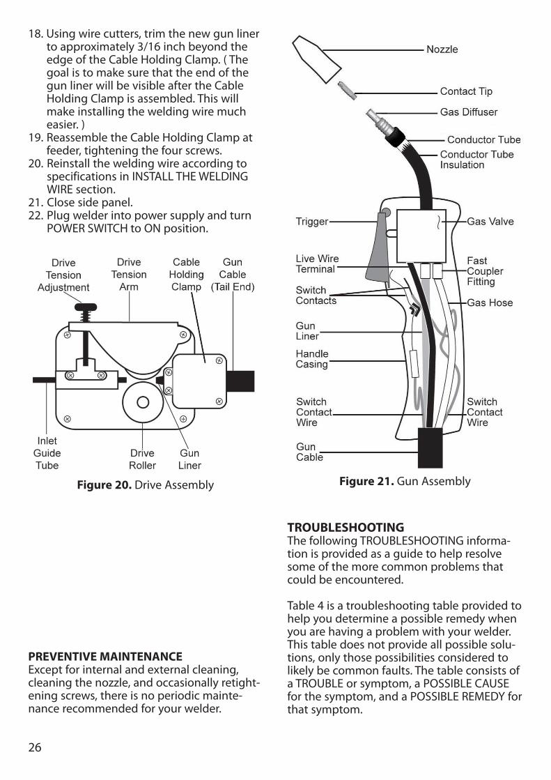
18. Using wire cutters, trim the new gun linerto approximately 3/16 inch beyond theedge of the Cable Holding Clamp. ( Thegoal is to make sure that the end of thegun liner will be visible after the CableHolding Clamp is assembled. This willmake installing the welding wire mucheasier. )
19. Reassemble the Cable Holding Clamp atfeeder, tightening the four screws.
20. Reinstall the welding wire according tospecifications in INSTALL THE WELDINGWIRE section.
21. Close side panel.22. Plug welder into power supply and turn
POWER SWITCH to ON position.
PREVENTIVE MAINTENANCEExcept for internal and external cleaning,cleaning the nozzle, and occasionally retight-ening screws, there is no periodic mainte-nance recommended for your welder.
TROUBLESHOOTINGThe following TROUBLESHOOTING informa-tion is provided as a guide to help resolvesome of the more common problems thatcould be encountered.
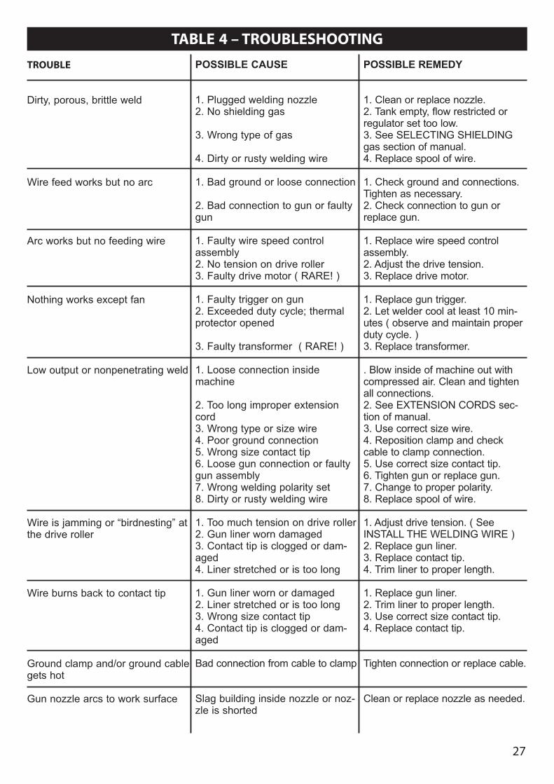
Table 4 is a troubleshooting table provided tohelp you determine a possible remedy whenyou are having a problem with your welder.This table does not provide all possible solu-tions, only those possibilities considered tolikely be common faults. The table consists ofa TROUBLE or symptom, a POSSIBLE CAUSEfor the symptom, and a POSSIBLE REMEDY forthat symptom.
26
Figure 20. Drive Assembly Figure 21. Gun Assembly
27
TABLE 4 – TROUBLESHOOTINGTROUBLE
Dirty, porous, brittle weld
Wire feed works but no arc
Arc works but no feeding wire
Nothing works except fan
Low output or nonpenetrating weld
Wire is jamming or “birdnesting” atthe drive roller
Wire burns back to contact tip
Ground clamp and/or ground cablegets hot
Gun nozzle arcs to work surface
POSSIBLE CAUSE
1. Plugged welding nozzle2. No shielding gas
3. Wrong type of gas
4. Dirty or rusty welding wire
1. Bad ground or loose connection
2. Bad connection to gun or faultygun
1. Faulty wire speed controlassembly2. No tension on drive roller3. Faulty drive motor ( RARE! )
1. Faulty trigger on gun2. Exceeded duty cycle; thermalprotector opened
3. Faulty transformer ( RARE! )
1. Loose connection insidemachine
2. Too long improper extensioncord3. Wrong type or size wire4. Poor ground connection 5. Wrong size contact tip6. Loose gun connection or faultygun assembly7. Wrong welding polarity set8. Dirty or rusty welding wire
1. Too much tension on drive roller2. Gun liner worn damaged 3. Contact tip is clogged or dam-aged4. Liner stretched or is too long
1. Gun liner worn or damaged 2. Liner stretched or is too long3. Wrong size contact tip4. Contact tip is clogged or dam-aged
Bad connection from cable to clamp
Slag building inside nozzle or noz-zle is shorted
POSSIBLE REMEDY
1. Clean or replace nozzle.2. Tank empty, flow restricted orregulator set too low.3. See SELECTING SHIELDINGgas section of manual.4. Replace spool of wire.
1. Check ground and connections.Tighten as necessary.2. Check connection to gun orreplace gun.
1. Replace wire speed controlassembly.2. Adjust the drive tension.3. Replace drive motor.
1. Replace gun trigger.2. Let welder cool at least 10 min-utes ( observe and maintain properduty cycle. )3. Replace transformer.
. Blow inside of machine out withcompressed air. Clean and tightenall connections.2. See EXTENSION CORDS sec-tion of manual.3. Use correct size wire.4. Reposition clamp and checkcable to clamp connection.5. Use correct size contact tip.6. Tighten gun or replace gun.7. Change to proper polarity.8. Replace spool of wire.
1. Adjust drive tension. ( SeeINSTALL THE WELDING WIRE )2. Replace gun liner.3. Replace contact tip.4. Trim liner to proper length.
1. Replace gun liner.2. Trim liner to proper length.3. Use correct size contact tip.4. Replace contact tip.
Tighten connection or replace cable.
Clean or replace nozzle as needed.
WIRE FEED WELDER PARTS LIST
28 28
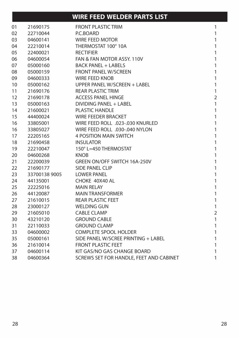
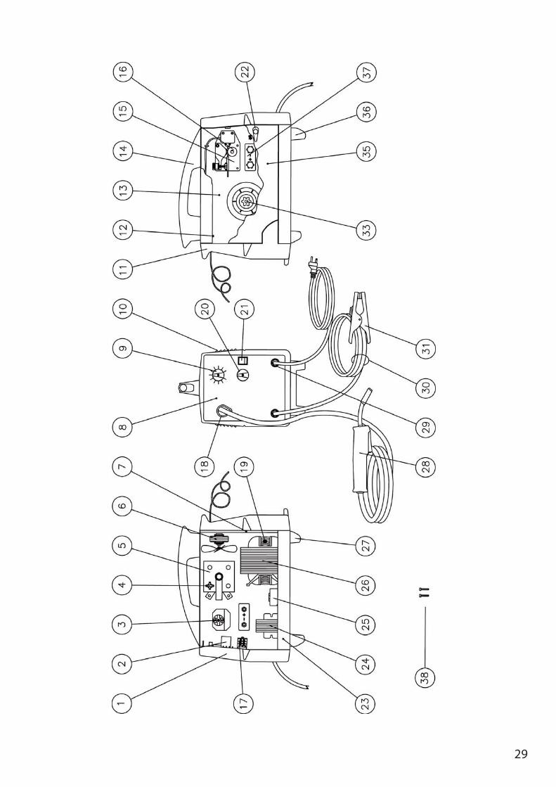
01 21690175 FRONT PLASTIC TRIM 102 22710044 P.C.BOARD 103 04600141 WIRE FEED MOTOR 104 22210014 THERMOSTAT 100° 10A 105 22400021 RECTIFIER 106 04600054 FAN & FAN MOTOR ASSY. 110V 107 05000160 BACK PANEL + LABELS 108 05000159 FRONT PANEL W/SCREEN 109 04600333 WIRE FEED KNOB 110 05000162 UPPER PANEL W/SCREEN + LABEL 111 21690176 REAR PLASTIC TRIM 112 21690178 ACCESS PANEL HINGE 213 05000163 DIVIDING PANEL + LABEL 114 21600021 PLASTIC HANDLE 115 44400024 WIRE FEEDER BRACKET 116 33805001 WIRE FEED ROLL .023-.030 KNURLED 116 33805027 WIRE FEED ROLL .030-.040 NYLON 117 22205165 4 POSITION MAIN SWITCH 118 21690458 INSULATOR 119 22210047 150° L=450 THERMOSTAT 120 04600268 KNOB 121 22200039 GREEN ON/OFF SWITCH 16A-250V 122 21690177 SIDE PANEL CLIP 123 33700138 9005 LOWER PANEL 124 44135001 CHOKE 40X40 AL 125 22225016 MAIN RELAY 126 44120087 MAIN TRANSFORMER 127 21610015 REAR PLASTIC FEET 128 23000127 WELDING GUN 129 21605010 CABLE CLAMP 230 43210120 GROUND CABLE 131 22110033 GROUND CLAMP 133 04600002 COMPLETE SPOOL HOLDER 135 05000161 SIDE PANEL W/SCREE PRINTING + LABEL 136 21610014 FRONT PLASTIC FEET 137 04600114 KIT GAS/NO GAS CHANGE BOARD 138 04600364 SCREWS SET FOR HANDLE, FEET AND CABINET 1
29
30
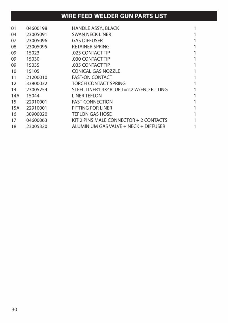
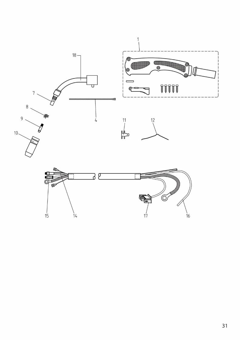
WIRE FEED WELDER GUN PARTS LIST
01 04600198 HANDLE ASSY., BLACK 104 23005091 SWAN NECK LINER 107 23005096 GAS DIFFUSER 108 23005095 RETAINER SPRING 109 15023 .023 CONTACT TIP 109 15030 .030 CONTACT TIP 109 15035 .035 CONTACT TIP 110 15105 CONICAL GAS NOZZLE 111 21200010 FAST-ON CONTACT 112 33800032 TORCH CONTACT SPRING 114 23005254 STEEL LINER1.4X4BLUE L=2,2 W/END FITTING 114A 15044 LINER TEFLON 115 22910001 FAST CONNECTION 115A 22910001 FITTING FOR LINER 116 30900020 TEFLON GAS HOSE 117 04600063 KIT 2 PINS MALE CONNECTOR + 2 CONTACTS 118 23005320 ALUMINIUM GAS VALVE + NECK + DIFFUSER 1
31
32
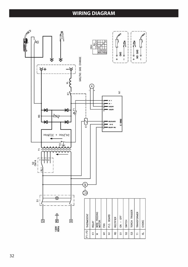
WIRING DIAGRAM
33
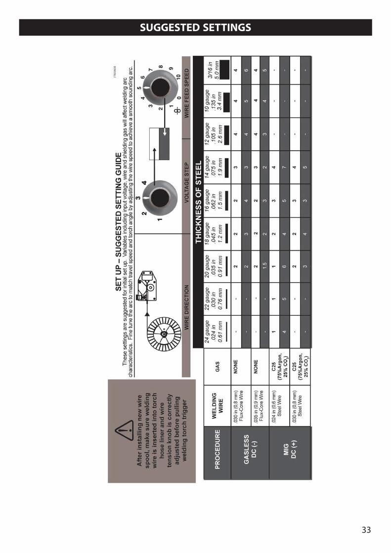
SUGGESTED SETTINGS

34
NOTES

35

77611241