Embed Size (px)
Citation preview
HT-PP System – Product range
HT-PP
Polypropylene waste water systemQuality Made in Germany

HT-PP System
The modified house discharge system from magnaplast.
It unites all the requirements of a modern house dis-
charge system from sound insulation/fire protection to
easy centimeter-marking installation. of course, all the
established properties such as low inflammability, chemi-
cal resistance and hot water resistance have been taken
on. What has come about is a qualitatively high-grade
house discharge pipe system with a maximum degree of
compliance to all the requirements.
Quality Made in Germany

Benefi ts andAdvantages of
the System

www.magnaplast.com
Discharge pipes and fi ttings HT-PP System
Just trust what you hearThose wishing to live comfortably today want to avoid dis-turbing noises. This is where the magnaplast HT easy-to-install, corrosion-resistant house discharge pipe system helps to raise the quality of living.
• CAN BE USED IN ALL FIELDS OF BUILDING CONSTRUCTION
• EXCELLENT MECHANICAL AND ACOUSTIC PROPERTIES
How sound arises in the waste water pipeImpact and flow noises result in airborne and structure-borne sounds at the piping walls. For instance, the im-pacting of water waste, which can reach relatively high speeds, induces noise at many points such as bends, branches and collecting lines. With magnaplast HT, the sanitary specialist has a soundproof house discharge pipe system which sets new standards.
• AIRBORNE NOISE• STRUCTURE-BORNE NOISE
Magnaplast HT avoids noise The modified basic material formula in the HT house dis-charge pipe system provides reliable sound insulation. It is a hot water-resistant pipe system suitable for pres-sureless discharge of waste water, according to DIN EN 12056 and DIN 1986-100.
• SOUNDPROOF• STOPS SOUND TRANSFER
Don't give noise a chance A DIN EN 14366 sound insulation test carried out by the Fraunhofer Institut für Bauphysik in Stuttgart(Test report P-BA 45-1/2009 of the 10.09.2010) on the new magnaplast HT system came up with acoustic figures of 26 dB(A). usual steel clamps with inlaid rubber and a 4 l/s flow rate were used in testing.
• 26 DB(A) ACCORDING TO DIN EN 14366
Strength and stability Magnaplast HT is corrosion-resistant, resistant to aggres-sive waste water and has a permanent low Inflammability as per DIN 4102 B1. There are no incrustations due to the smooth surface. Magnaplast HT is available from DN 32 to DN 160 . The reliable push-fit connection makes the system easy to install and fulfils all expectations.
• CORROSION RESISTANT• EASY-TO-INSTALL• B1 FLAME RESISTANT
quality guarantee our HT pipes and fittings are quality labeled and are subject to constant quality checks. We run a certificated quality management system based on DIN EN ISo 9001 DQS Frankfurt.
• DIN EN ISO 9001• CONSTANT QUALITY CHECKS
quality of livingParticularly in the matter of raised requirements in housing, magnaplast HT satisfies all ecological and economical expectations and contributes decisively to raising the quality of living – and thus the value of the property.
• RAISES THE PROPERTY VALUE• MEETS BOTH ECONOMICAL AND
ECOLOGICAL CRITERIA
5
www.magnaplast.com
6HT-PP System Discharge pipes and fittings
HT-PP SystemDischarge pipes and fittings
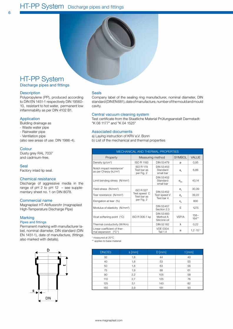
Description Polypropylene (PP), produced according to DIN EN 1451-1 respectively DIN 19560-10, resistant to hot water, permanent low inflammability as per DIN 4102 B1.
ApplicationBuilding drainage as - Waste water pipe- Rainwater pipe- Ventilation pipe(also see areas of use: DIN 1986-4).
ColourDusty grey RAL 7037 and cadmium-free.
SealFactory inlaid lip seal.
Chemical resistanceDischarge of aggressive media in the range of pH 2 to pH 12 – see supple-mentary sheet no. 1 on DIN 8078.
Commercial nameMagnaplast HT-Abflussrohr (magnaplast High-Temperature Discharge Pipe)
MarkingPipes and fittingsPermanent marking with manufacturer la-bel, nominal diameter, DIN standard (DIN EN 1451-1), date of manufacture, (fittings also marked with details).
MEcHANIcAL AND THERMAL PRoPERTIES
Property Measuring method SyMBoL VALuE
Density (g/cm3) ISo R 1183 DIN 53 479 p 0,95
Notch impact resistance* as per charpy (kJ/m2)
ISo R 179 Test bar as per Fig. 2
DIN 53 453 Standard small bar
ak 6,86
Limit bending stress (N/mm2)DIN 53 452 Standard small bar
σbG 43,14
yield stress (N/mm2) ISo R 527Test speed c
Test bar as per Fig. 2
DIN 53 452Test speed V
Test bar 4
σS 30,39
Tear resistance (N/mm2) σR 39,22
Elongation at tear (%) εR 800
Modulus of elasticity (N/mm2) DIN 53 457 Section 2.3 E 1275
Vicat softening point (°c) ISo R 306-1 kpDIN 53 460 Method A Silicone oil
VSP/A 158 – 164**
Thermal conductivity (W/Km) DIN 52 162 λ 0,22
Linear coefficient of ther-mal expansion (°c-1)
VDE 0304 Teil 1.4 α 1,2 ·10-4
* measured at 20°c** applies to base material
DN(oD) s [mm] D [mm] t [mm]
32 1,8 44 40
40 1,8 53 55
50 1,8 63 56
75 1,9 88 61
90 2,2 105 58
110 2,7 125 76
125 3,1 143 82
160 3,9 181 90
Sealscompany label of the sealing ring manufacturer, nominal diameter, DIN standard (DIN EN 681), date of manufacture, number of the mould and mould cavity.
Central vacuum cleaning systemTest certificate from the Staatliche Material Prüfungsanstalt Darmstadt:"K 08 1177" and "K 04 1525"
Associated documentsa) Laying instruction of KRV e.V. Bonnb) List of the mechanical and thermal properties
Material Properties

Product range HT-PP System
www.magnaplast.com
Discharge pipes and fi ttings HT-PP System9
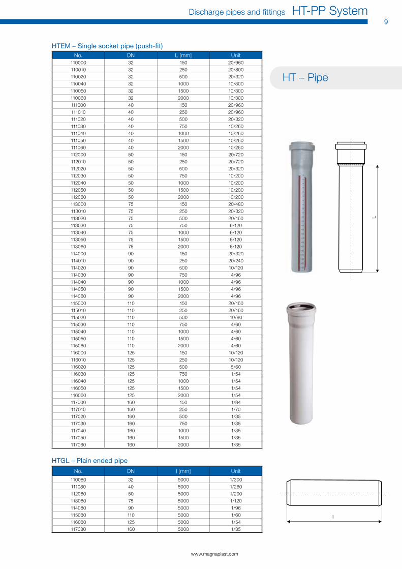
HT – Pipe
L
HTEM – Single socket pipe (push-fi t)No. DN L [mm] unit
110000 32 150 20/960
110010 32 250 20/800
110020 32 500 20/320
110040 32 1000 10/300
110050 32 1500 10/300
110060 32 2000 10/300
111000 40 150 20/960
111010 40 250 20/960
111020 40 500 20/320
111030 40 750 10/260
111040 40 1000 10/260
111050 40 1500 10/260
111060 40 2000 10/260
112000 50 150 20/720
112010 50 250 20/720
112020 50 500 20/320
112030 50 750 10/200
112040 50 1000 10/200
112050 50 1500 10/200
112060 50 2000 10/200
113000 75 150 20/480
113010 75 250 20/320
113020 75 500 20/160
113030 75 750 6/120
113040 75 1000 6/120
113050 75 1500 6/120
113060 75 2000 6/120
114000 90 150 20/320
114010 90 250 20/240
114020 90 500 10/120
114030 90 750 4/96
114040 90 1000 4/96
114050 90 1500 4/96
114060 90 2000 4/96
115000 110 150 20/160
115010 110 250 20/160
115020 110 500 10/80
115030 110 750 4/60
115040 110 1000 4/60
115050 110 1500 4/60
115060 110 2000 4/60
116000 125 150 10/120
116010 125 250 10/120
116020 125 500 5/60
116030 125 750 1/54
116040 125 1000 1/54
116050 125 1500 1/54
116060 125 2000 1/54
117000 160 150 1/84
117010 160 250 1/70
117020 160 500 1/35
117030 160 750 1/35
117040 160 1000 1/35
117050 160 1500 1/35
117060 160 2000 1/35
HTGL – Plain ended pipe
No. DN l [mm] unit
110080 32 5000 1/300
111080 40 5000 1/260
112080 50 5000 1/200
113080 75 5000 1/120
114080 90 5000 1/96
115080 110 5000 1/60
116080 125 5000 1/54
117080 160 5000 1/35

www.magnaplast.com
10HT-PP System Discharge pipes and fittings
HT – FittingHTB – Bend 15º
No. DN α z1 z2 l1 unit
110100 32 15° 3 8 42 20/1400
111100 40 15° 5 9 44 20/960
112100 50 15° 5 9 46 20/960
113100 75 15° 7 11 51 20/480
114100 90 15° 6 12 54 20/480
115100 110 15° 9 17 58 20/240
116100 125 15° 10 17 64 20/160
117100 160 15° 13 22 73 10/80
HTB – Bend 30º
No. DN α z1 z2 l1 unit
110110 32 30° 6 10 42 20/1400
111110 40 30° 7 11 44 20/960
112110 50 30° 9 13 46 20/960
113110 75 30° 12 16 51 20/480
114110 90 30° 13 18 54 20/480
115110 110 30° 17 24 58 20/240
116110 125 30° 19 25 64 20/160
117110 160 30° 24 32 73 10/80
HTB – Bend 45º
No. DN α z1 z2 l1 unit
110120 32 45° 9 12 42 20/1400
111120 40 45° 10 14 44 20/960
112120 50 45° 12 16 46 20/960
113120 75 45° 16 12 51 20/480
114120 90 45° 20 25 54 20/480
115120 110 45° 17 24 58 20/240
116120 125 45° 28 34 64 20/160
117120 160 45° 36 46 73 5/60
HTB – Bend 67º
No. DN α z1 z2 l1 unit
110130 32 67° 14 17 42 20/1400
111130 40 67° 16 20 44 20/960
112130 50 67° 22 23 46 20/960
113130 75 67° 28 31 51 20/480
114130 90 67° 32 36 54 20/240
115130 110 67° 40 44 58 20/160
116130 125 67° 40 44 58 20/120
HTB – Bend 87º
No. DN α z1 z2 l1 unit
110140 32 87° 19 23 42 20/1400
111140 40 87° 23 26 42 20/960
112140 50 87° 28 31 46 20/960
113140 75 87° 40 43 51 20/480
114140 90 87° 46 49 54 20/240
115140 110 87° 57 61 58 20/160
116140 125 87° 65 71 64 10/120
117140 160 87° 83 96 73 5/60

www.magnaplast.com
Discharge pipes and fittings HT-PP System11
L
HTEA – Branch 45º
No. DN · z1 z2 z3 L [mm] unit
110200 32/32 45° 9 40 40 95 20/960
111200 40/40 45° 10 50 50 104 20/960
112210 50/40 45° 5 57 55 106 20/480
112200 50/50 45° 12 62 62 125 20/480
113210 75/50 45° 1 79 74 128 20/480
113200 75/75 45° 18 92 92 164 20/240
114220 90/50 45° 9 90 82 127 20/240
114210 90/75 45° 9 103 100 163 20/240
114200 90/90 45° 20 110 110 184 20/160
115220 110/50 45° 17 104 94 152 20/240
115210 110/75 45° 1 120 115 175 20/160
115200 110/110 45° 25 135 135 218 10/80
116210 125/110 45° 18 144 142 224 5/60
116200 125/125 45° 28 152 152 249 5/60
117210 160/110 45° 1 228 158 242 5/40
117200 160/160 45° 36 194 1944 309 5/30
HTEA – Branch 67º
No. DN · z1 z2 z3 L [mm] unit
110300 32/32 67° 14 27 27 86 20/960
111300 40/40 67° 16 33 33 99 20/960
112310 50/40 67° 14 39 35 95 20/480
112300 50/50 67° 20 41 41 110 20/480
113310 75/50 67° 14 54 46 115 20/480
113300 75/75 67° 28 66 60 143 20/240
115320 110/50 67° 8 73 54 125 20/240
115310 110/75 67° 22 78 68 148 20/160
115300 110/110 67° 40 88 88 186 10/120
HTEA – Branch 87º
No. DN · z1 z2 z3 L [mm] unit
110400 32/32 87° 19 21 21 85 20/960
111400 40/40 87° 23 25 25 92 20/960
112410 50/40 87° 23 30 25 94 20/480
112400 50/50 87° 28 30 30 109 20/480
113410 75/50 87° 27 43 31 112 20/480
113400 75/75 87° 40 43 43 138 20/240
114420 90/50 87° 26 50 31 111 20/240
114410 90/75 87° 39 51 44 137 20/240
114400 90/90 87° 56 70 51 161 20/160
115420 110/50 87° 28 60 34 120 20/240
115410 110/75 87° 40 60 46 113 20/160
115400 110/110 87° 57 64 64 183 10/120
116410 125/110 87° 58 70 64 191 5/60
116400 125/125 87° 65 71 71 205 5/60
117410 160/110 87° 66 87 64 219 5/60
117400 160/160 87° 83 91 91 253 4/48
L

www.magnaplast.com
12HT-PP System Discharge pipes and fi ttings
HTU – Coupler
No. DN l [mm] unit
110500 32 93 20/1400
111500 40 103 20/960
112500 50 105 20/960
113500 75 111 20/480
114500 90 98 20/480
115500 110 128 20/240
116500 125 120 20/160
117500 160 163 15/120
HTMM – Double socket
No. DN l [mm] unit
110510 32 93 20/1400
111510 40 103 20/960
112510 50 105 20/960
113510 75 111 20/480
114510 90 98 20/480
115510 110 128 20/240
116510 125 116 20/160
117510 160 163 15/120
HTAM – Single socket
No. DN l [mm] unit
111810 40 113 20/1200
112810 50 116 20/480
113810 75 96,5 20/480
115810 110 123 20/240
HTL – Long socket
No. DN l [mm] L [mm] unit
111800 40 155 48 20/960
112800 50 211 54 20/480
113800 75 222 57 20/480
114800 90 151 60 20/480
115800 110 255 68 20/160
L
www.magnaplast.com
Discharge pipes and fi ttings HT-PP System13
L
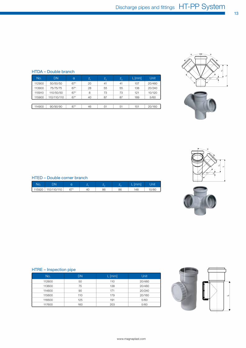
HTED – Double corner branch
No. DN · z1 z2 z3 L [mm] unit
115920 110/110/110 67° 40 86 86 148 10/80
HTDA – Double branch
No. DN · z1 z2 z3 L [mm] unit
112900 50/50/50 67° 20 41 41 107 20/480
113900 75/75/75 67° 28 55 55 138 20/240
115910 110/50/50 67° 8 73 73 121 10/120
115900 110/110/110 67° 40 87 87 189 5/60
114900 90/90/90 87° 46 51 51 151 20/160
HTrE – Inspection pipe
No. DN L [mm] unit
112600 50 110 20/480
113600 75 138 20/480
114600 90 171 20/240
115600 110 179 20/160
116600 125 191 5/60
117600 160 203 5/60
L

www.magnaplast.com
14HT-PP System Discharge pipes and fi ttings
HT – Plug-in socket Dn 110/110
No. DN d1 d2 d3 h [mm] unit
115750 110/110 90 111,5 126,7 108 20/240
HT – reducer Dn 50/40 short
No. DN d1 d2 d3 h [mm] unit
112715 50/40 50 41,2 59,5 61,5 20/1400
HTr – reducer, eccentric
No. DN z1 h [mm] unit
112720 50/32 17 68 20/960
112710 50/40 12 64 20/960
113710 75/50 21 72 20/480
114720 90/50 29 83 20/480
114710 90/75 17 71 20/480
115720 110/50 40 102 20/480
115710 110/75 26 89 20/480
115700 110/90 17 75 20/240
116710 125/110 15 79 20/240
117710 160/110 38,5 118 20/160
117700 160/125 28 101 20/160
HTr – reducer, eccentric, short
No. DN z1 h [mm] unit
111710 40/32 31,5 50,5 20/1400
113715 75/50 30,9 53 20/480
115725 110/50 30,5 58 20/480
115715 110/75 39,4 59 20/480
h
HTrI – Inner reducer
No. DN d1 d2 d3 h [mm] unit
115770 110/50 90 50,8 60,3 44 20/960
115760 110/75 90 75,9 85,1 49,2 20/480
h
d2
d3
d1
d2
d3
d1
h
d2
d3
d1
h
h

www.magnaplast.com
Discharge pipes and fittings HT-PP System15
h
HTM – Plug
No. DN h [mm] unit
110620 32 39 100/7000
111620 40 33,5 20/2880
112620 50 34 20/2880
113620 75 39 20/2880
114620 90 39 20/960
115620 110 39 20/960
116620 125 43 20/480
117620 160 60 20/480
HTSW – Siphon bend
No. DN d1 z1 z2 L1 unit
111910 40/30 40 24,5 22 75 20/960
111920 40/40 50 25 26 75,5 20/960
112930 50/30 47 23,5 23 86,4 1120/20
112940 50/40 50 30 32 81,5 20/960
112950 50/50 60 28 30 81 20/960
HTDSW – Double siphon bend 90°
No. DN d1 z1 z2 L1 unit
112970 40/50/40 50 28,5 33 76,5 20/480
HTS – Connection piece to iron pipes
No. DN d [mm] l [mm] L [mm] unit
111900 40/40 50 80 46 20/2880
112910 50/40 50 76 46 20/2880
112920 50/50 60 80 50 20/960
HTUG – Connection piece to cast-iron pipe
No. DN d6 l [mm] L [mm] unit
112820 50 72 116 61 20/960
113820 75 92 118 57 20/480
115820 110 124 130 64 20/480
L
d
d
L
L
d

HT – Accessories
www.magnaplast.com
16HT-PP System Discharge pipes and fi ttings
HT – Lip seal
No. DN unit
880000 32 40
880010 40 33
880020 50 34
880030 75 34
880040 90 32
880050 110 39
880070 125 25
880080 160 31
HT – GA-Set gasket
No. DN unit
881000 50 50
881010 75 30
881020 110 20
HT – nBr gasket (oil resistant)
No. DN unit
880210 40 40
880220 50 34
880230 75 50
880240 90 32
880250 110 39
880270 125 38
880280 160 31
HT – replacement cover for inspection pipe
No. DN unit
812600 50 -
813600 75 -
815600 110 -
HTGM – Gasket for siphon bend
No. DN D1 D2 unit
881200 40/30 A 40 28-34 20
881210 40/30 B 50 28-34 20
881220 40/40 c 50 38-44 20
881230 40/50/1 1/4 47 28-34 20
881240 50/30 D 60 28-34 20
881250 50/40 E 60 38-44 20
881260 50/50 F 60 48-54 20
D1

www.magnaplast.com
Discharge pipes and fittings HT-PP System17
MH
HT – Lubricant
No. unit
881800 50/1750
881810 50/1500
881820 24/720
HT – magnaplast BS Fire protection sleeve
No. Sleeve size carton unit
881600 50 25 1
881610 75–78 25 1
881620 90 10 1
881630 110 10 1
881650 160 5 1
HT – Pull-out protection
No. DN Sleeve size carton unit
881500 DN 50 50 50 1
881510 DN 75 75 30 1
881520 DN 90 90 20 1
881530 DN 110 110 20 1
881540 DN 125 125 9 1
881550 DN 160 160 10 1
HT – Gasket for Single sockets
No. DN unit
881400 40 -
881410 50 -
881420 75 -
881430 110 -

Fire Protection
www.magnaplast.com
Discharge pipes and fi ttings HT-PP System19
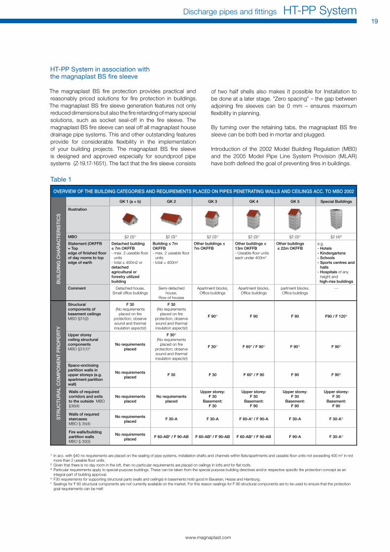
HT-PP System in association with the magnaplast BS fi re sleeve
The magnaplast BS fi re protection provides practical and reasonably priced solutions for fi re protection in buildings. The magnaplast BS fi re sleeve generation features not only reduced dimensions but also the fi re retarding of many special solutions, such as socket seal-off in the fi re sleeve. The magnaplast BS fi re sleeve can seal off all magnaplast house drainage pipe systems. This and other outstanding features provide for considerable fl exibility in the implementation of your building projects. The magnaplast BS fi re sleeve is designed and approved especially for soundproof pipe systems (Z-19.17-1651). The fact that the fi re sleeve consists
of two half shells also makes it possible for Installation to be done at a later stage. "Zero spacing" – the gap between adjoining fi re sleeves can be 0 mm – ensures maximum fl exibility in planning.
By turning over the retaining tabs, the magnaplast BS fi re sleeve can be both bed in mortar and plugged.
Introduction of the 2002 Model Building Regulation (MB0) and the 2005 Model Pipe Line System Provision (MLAR) have both defi ned the goal of preventing fi res in buildings.
OVERVIEW OF THE BUILDING CATEGORIES AND REQUIREMENTS PLACED ON PIPES PENETRATING WALLS AND CEILINGS ACC. TO MBO 2002
BU
ILD
ING
CH
AR
AC
TE
RIS
TIC
S
GK 1 (a + b) GK 2 GK 3 GK 4 GK 5 Special Buildings
Illustration
MBO §2 (3)1) §2 (3)1) §2 (3)1) §2 (3)1) §2 (3)1) §2 (4)2)
Statement (OKFFB = Top edge of fi nished fl oor of day rooms to top edge of earth
Detached building ≤ 7m OKFFB- max. 2 useable floor
units- total ≤ 400m2 ordetached agricultural or forestry utilized building
Building ≤ 7m OKFFB- max. 2 useable fl oor
units- total ≤ 400m2
Other buildings ≤ 7m OKFFB
Other buildings ≤ 13m OKFFB- useable floor units each under 400m2
Other buildings ≤ 22m OKFFB
e.g.- Hotels- Kindergartens- Schools- Sports centres and
halls- Hospitals of any
height and high-rise buildings
Comment Detached house, Small office buildings
Semi-detached house,
Row of houses
Apartment blocks, office buildings
Apartment blocks, office buildings
partment blocks, office buildings
---
ST
RU
CT
UR
AL
CO
MP
ON
EN
T P
RO
PE
RT
Y
Structural components of basement ceilings MBo §31(2)
F 30(No requirements
placed on fi re protection; observe sound and thermal insulation aspects!)
F 30(No requirements
placed on fi re protection; observe sound and thermal insulation aspects!)
F 904) F 90 F 90 F90 / F 1203)
Upper storey ceiling structural components MBo §31(1)2)
No requirements placed
F 302)
(No requirements placed on fi re
protection; observe sound and thermal insulation aspects!)
F 302) F 60* / F 902) F 902) F 902)
Space-enclosing partition walls in upper storeys (e.g. apartment partition wall)
No requirements placed
F 30 F 30 F 60* / F 90 F 90 F 903)
Walls of required corridors and exits to the outside MBo §36(4)
No requirements placed
No requirements placed
Upper storey:F 30
Basement:F 30
Upper storey:F 30
Basement:F 90
Upper storey:F 30
Basement:F 90
Upper storey:F 30
Basement:F 90
Walls of required staircases MBo § 35(4)
No requirements placed
F 30-A F 30-A F 60-A* / F 90-A F 30-A F 30-A3)
Fire walls/building partition walls MBo § 30(3)
No requirements placed
F 60-AB* / F 90-AB F 60-AB* / F 90-AB F 60-AB* / F 90-AB F 90-A F 30-A3)
1) In acc. with §40 no requirements are placed on the sealing of pipe systems, installation shafts and channels within fl ats/apartments and useable fl oor units not exceeding 400 m2 in not more than 2 useable fl oor units.
2) Given that there is no day room in the loft, then no particular requirements are placed on ceilings in lofts and for fl at roofs.3) Particular requirements apply to special-purpose buildings. These can be taken from the special purpose building directives and/or respective specifi c fi re protection concept as an
integral part of building approval.4) F30 requirements for supporting structural parts (walls and ceilings) in basements hold good in Bavarian, Hesse and Hamburg.* Sealings for F 60 structural components are not currently available on the market. For this reason sealings for F 90 structural components are to be used to ensure that the protection
goal requirements can be met!
Table 1
www.magnaplast.com
20HT-PP System Discharge pipes and fittings
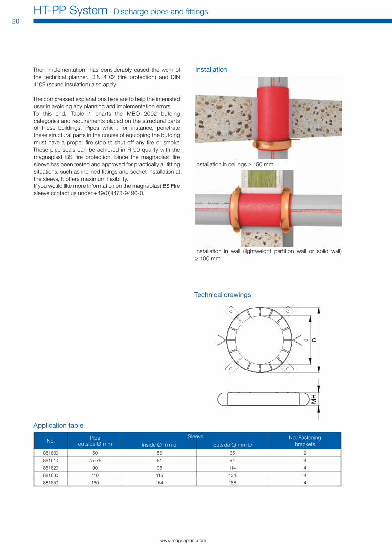
Installation
Installation in ceilings ≥ 150 mm
Installation in wall (lightweight partition wall or solid wall) ≥ 100 mm
Technical drawings
MH
d D
Their implementation has considerably eased the work of the technical planner. DIN 4102 (fire protection) and DIN 4109 (sound insulation) also apply.
The compressed explanations here are to help the interested user in avoiding any planning and implementation errors.To this end, Table 1 charts the MBo 2002 building categories and requirements placed on the structural parts of these buildings. Pipes which, for instance, penetrate these structural parts in the course of equipping the building must have a proper fire stop to shut off any fire or smoke. These pipe seals can be achieved in R 90 quality with the magnaplast BS fire protection. Since the magnaplast fire sleeve has been tested and approved for practically all fitting situations, such as inclined fittings and socket installation at the sleeve, It offers maximum flexibility.If you would like more information on the magnaplast BS Fire sleeve contact us under +49(0)4473-9490-0.
Application table
No. Pipeoutside Ø mm
Sleeve No. Fastening bracketsinside Ø mm d outside Ø mm D
881600 50 56 65 2
881610 75–78 81 94 4
881620 90 96 114 4
881630 110 116 134 4
881650 160 164 188 4

www.magnaplast.com
Discharge pipes and fittings HT-PP System21
Installation Instructions
Install pipe (and possibly the sound insulation hose included in the supply)
Select sleeve size
Plugging the retaining tab with the jointly supplied fixing set (as an option the tabs can also be bent through 90° and bedded in mortar!)
close remaining or ring gap in a flue gas-tight manner
If necessary, mark and set up the fixing points
Fill in the identification plate as supplied and attach next to the fire-retarding seal.
magnaplast

www.magnaplast.com
22HT-PP System Discharge pipes and fittings
Special applications
Straight pipe bushing (possibly with sound insulation hose ≤ 4 mm)
Inclined bushing
Straight pipe bushing with socket at the sleeve
Zero spacing one under the other
www.magnaplast.com
Discharge pipes and fittings HT-PP System23
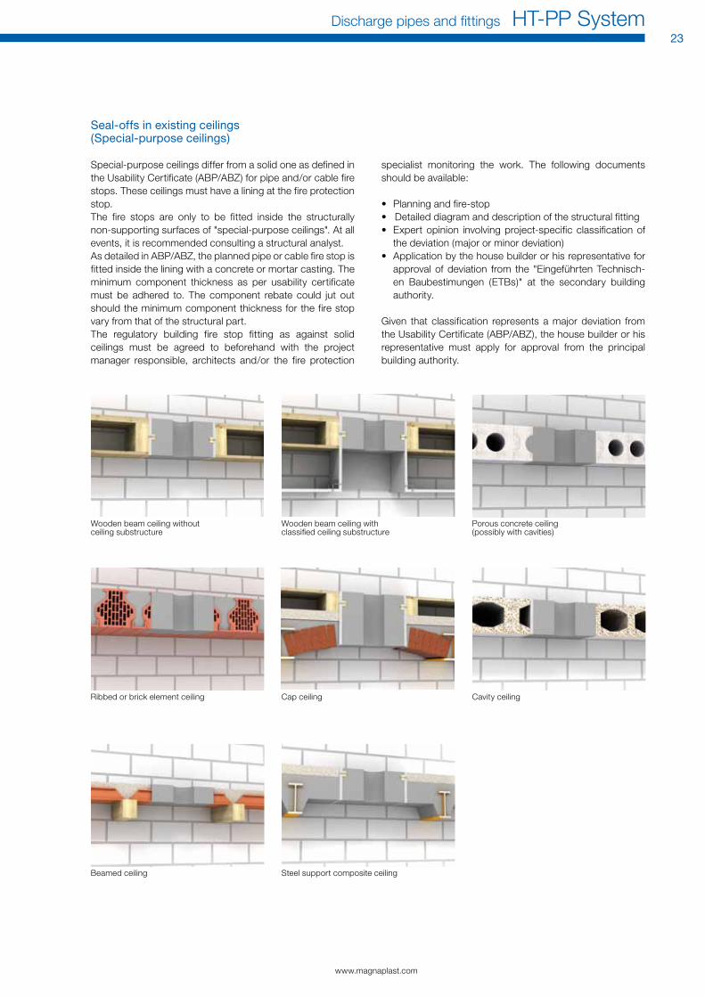
Seal-offs in existing ceilings (Special-purpose ceilings)
Special-purpose ceilings differ from a solid one as defined in the usability certificate (ABP/ABZ) for pipe and/or cable fire stops. These ceilings must have a lining at the fire protection stop. The fire stops are only to be fitted inside the structurally non-supporting surfaces of "special-purpose ceilings". At all events, it is recommended consulting a structural analyst.As detailed in ABP/ABZ, the planned pipe or cable fire stop is fitted inside the lining with a concrete or mortar casting. The minimum component thickness as per usability certificate must be adhered to. The component rebate could jut out should the minimum component thickness for the fire stop vary from that of the structural part.The regulatory building fire stop fitting as against solid ceilings must be agreed to beforehand with the project manager responsible, architects and/or the fire protection
specialist monitoring the work. The following documents should be available:
• Planning and fire-stop• Detailed diagram and description of the structural fitting• Expert opinion involving project-specific classification of
the deviation (major or minor deviation)• Application by the house builder or his representative for
approval of deviation from the "Eingeführten Technisch-en Baubestimungen (ETBs)" at the secondary building authority.
Given that classification represents a major deviation from the usability certificate (ABP/ABZ), the house builder or his representative must apply for approval from the principal building authority.
Wooden beam ceiling without ceiling substructure
Porous concrete ceiling (possibly with cavities)
Ribbed or brick element ceiling cap ceiling cavity ceiling
Beamed ceiling Steel support composite ceiling
Wooden beam ceiling with classified ceiling substructure

Installation Instructions
Pipes and fi ttings made of Polypropylene for waste water and underground drainage systems.
Pipes and fi ttings made of Polypropylene for waste water

www.magnaplast.com
Discharge pipes and fi ttings HT-PP System25
1. FIELD oF APPLICATIonThe following instruction describes how the HT pipes and fi ttings - for discharging media in foul water, rainwater and ventilation pipes inside buildings - are to be handled, stored and mounted.orders for laying the detailed waste water piping systems are only to be placed with companies with a pool of trained op-erating personnel. The instruction is only for installing genu-ine pipes and fi ttings involving the use of the genuine sealing elements and lubricants.
2. TrAnSPorT, HAnDLInG AnD STorAGEunpalletized pipes should be laid completely fl at along their entire length during transport. Heavy shocks – especially in freezing temperatures – must be avoided. For loading and unloading wide canvass lifting harnesses must be used.Pipes and fi ttings may be stored outdoors; pre-installed seal-ing elements should not be stored longer than three years.The following points must be observed when laying pipes:a) Pipes must be stored in a stable position so that no defor-
mation or sagging can take place.b) The pipe sockets must be free, both in the vertical and
horizontal directions.c) A stacking height of 1.5 meters should not be exceeded.
3. CUTTInG To LEnGTH AnD BEvELInGcutting pipes to length is done at right angles by using a pipe cutter or a fi ne-toothed saw. The cut edges must be deburred. The pipe end is then beveled with a beveling tool or by using a coarse fi le at an angle of approx. 15° as shown in the following fi gure.
BEVELING DIMENSIoNS
DN 32 40 50 75 90 110 125 160
b[mm] 3,5 3,5 3,5 3,5 4,5 4,5 5,0 6,0
4. ConnECTInG PIPES AnD FITTInGS
a) clean the pipe spigot end and clean the socket.
b) check the condition and quality of the factory pre-installed sealing element.
c) Apply factory supplied lubricant lightly and evenly on the bevelled surface only of the spigot end.
When inserting, the ring seal must be free of lubricant. center up the spigot end of the pipe and push until the pipe end reaches the end of the socket.
d) Length changes between pipes and fi ttings as well as be-tween pipes within the spigot and socket connection are possible.
www.magnaplast.com
26HT-PP System Discharge pipes and fittings
It is required that the pipe be pulled back a maximum of 10 mm. For normal HT pipes, that means a maximum length of 2 meters.The spigot ends of fittings may remain fully pushed into the socket.
Pipes must be secured with pipe clamps to prevent slippage during subsequent installation work. This is done after tak-ing into account the necessary measures concerning length changes.
5. PIPE CLAMPS In general, plastic waste water pipe systems must be installed so that they are not under mechanical stresses and are al-lowed to undergo natural length changes. As a rule, securing pipes is done with pipe clamps that have an inner lining and that are appropriate for the given outer diameter and which completely circumvent the pipe. If no inner lining is used inside the clamp, then the inside edge of the clamp must be rounded off and the inside surface must be smooth. only an inner lining that is recommended by the pipe manufacturer can be used.Inner linings made of PVc or pipe hooks must not be used!
5.1 FIxED CLAMPSFixed points are achieved by completely tightening the pipe clamps in a piping system. They must be positioned so that each pipe length is prevented from slipping. The fixed clamps must be positioned directly behind the socket for pipe with sockets.Fittings or groups of fittings must always be laid out as fixed points.
5.2 LooSE CLAMPSPipe clamps which are not completely tightened (loose clamps) must allow unimpaired longitudinal movement of the pipeline after installation. For this reason the inside diameter of the clamp must be slightly bigger than the outside diameter of the pipe when installed.
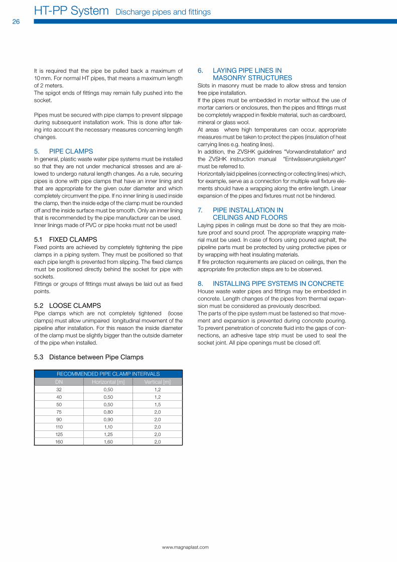
5.3 Distance between Pipe Clamps
REcoMMENDED PIPE cLAMP INTERVALS
DN Horizontal [m] Vertical [m]32 0,50 1,2
40 0,50 1,2
50 0,50 1,5
75 0,80 2,0
90 0,90 2,0
110 1,10 2,0
125 1,25 2,0
160 1,60 2,0
6. LAyInG PIPE LInES In MASonry STrUCTUrES
Slots in masonry must be made to allow stress and tension free pipe installation.If the pipes must be embedded in mortar without the use of mortar carriers or enclosures, then the pipes and fittings must be completely wrapped in flexible material, such as cardboard, mineral or glass wool.At areas where high temperatures can occur, appropriate measures must be taken to protect the pipes (insulation of heat carrying lines e.g. heating lines).In addition, the ZVSHK guidelines "Vorwandinstallation" and the ZVSHK instruction manual "Entwässerungsleitungen" must be referred to.Horizontally laid pipelines (connecting or collecting lines) which, for example, serve as a connection for multiple wall fixture ele-ments should have a wrapping along the entire length. Linear expansion of the pipes and fixtures must not be hindered.
7. PIPE InSTALLATIon In CEILInGS AnD FLoorS
Laying pipes in ceilings must be done so that they are mois-ture proof and sound proof. The appropriate wrapping mate-rial must be used. In case of floors using poured asphalt, the pipeline parts must be protected by using protective pipes or by wrapping with heat insulating materials.If fire protection requirements are placed on ceilings, then the appropriate fire protection steps are to be observed.
8. InSTALLInG PIPE SySTEMS In ConCrETEHouse waste water pipes and fittings may be embedded in concrete. Length changes of the pipes from thermal expan-sion must be considered as previously described.The parts of the pipe system must be fastened so that move-ment and expansion is prevented during concrete pouring. To prevent penetration of concrete fluid into the gaps of con-nections, an adhesive tape strip must be used to seal the socket joint. All pipe openings must be closed off.

www.magnaplast.com
Discharge pipes and fittings HT-PP System27
9. ConnECTIon To PIPES oF oTHEr MATErIALS AnD PIPE CUTTInGS
To connect HT pipes to other pipe system parts made of some other material, the appropriate fittings and sealing materials from the manufacturer must be used.
Connection to cast-iron pipe socket
Connection to steel pipe socket
Connection to stoneware pipe socket
Connection to fibre cement pipe spigot end
Connection to fibre cement pipe socket
Connection to SML pipe
10. SUBSEqUEnT ConnECTIon oF PIPES AnD FITTInGS
If a connection must be done to an existing line, then fittings and components made by the manufacturer must be used.a) When using couplers a sufficiently long pipe length (length
of the fitting 2d) is cut out, the ends of the pipe are then to beveled and the branch connector is then installed. The remaining space in the line is closed off by inserting an appropriately long pipe length and two couplers (Fig. A).
≈ 2d
Pipe leftover
Couplers
Long socket
Couplers
Subsequent connection
Fig. A Fig. B
b) If long sockets are used, then a length of pipe that equals the length of the fitting plus the insert depth is cut out. The long socket is then inserted all the way to the end and the fitting is installed by using a coupler. Afterwards the spigot end of the long socket is to be inserted in the other socket end of the fitting (Fig B).
Double sealHT pipe
cast-iron pipe with socket
Sealing elementHT pipe Stoneware socket
HT pipe Stoneware socketconnector
HT pipe HT pipe
Rubber hose connector
Fibre cement pipe
HT pipe
Rubber hose section
Rubber grooved ring
Fibre cement pipe socket
HT pipe SML pipeconnector

www.magnaplast.com
28HT-PP System Discharge pipes and fittings
11. PrEPArInG AnD USInG SMooTH PIPES AnD LEFTovEr PIECES
cutting, using and preparing leftover pieces (pipes with plain ends) can be done by using double sockets, couplers and sin-gle sockets.When using these connectors, a maximum length of 2 meters should not be exceeded when laying pipes with plain ends. They must be laid in accordance with the following installation regulation. It must be adhered to ensure compensation for expansion (see linear expansion).The instructions of the pipe manufacturer in question are to be observed when using thick-walled, mineral-reinforced pipe systems and setting up welded joints. Decisive in horizontal in-stallation are the pipe clamp intervals for horizontal pipe lines.
max. 2m (max. 3m given thick-walled mineral-reinforced pipes: - max. 3m - lengths over 2meters
with extra loose clamp in the middle)
max. 2m (max. 3m given thick -walled mineral -reinforced pipes: - max. 3 m - lengths over
2 meters with extra loose clamp in the middle)
max. 2m (max. 3m given thick-walled mineral-reinforced pipes: - max. 3m - lengths over 2meters
with extra loose clamp in the middle)
max. 2 m
Double sockets Couplers
Single sockets Adhesive sockets

chemicalResistance

www.magnaplast.com
30HT-PP System Discharge pipes and fittings
Chemical resistance of Polypropylene – HT-PP System
chemicals concentrate[%]
Temp. [°c]
20 60 100
Acetone1 100 + °
Ammonia, gaseous 100 + +
Ammonia, aq. conc. + +
Ammonia, aq. 10 + +
Amyl alcohol, pure + +
Acetic anhydride 100 +
Aniline 100 + +*
Benzaldehyde 100 +
Benzaldehyde, aq. sat. +
Petrol (see Industrial liquids)
Benzene 100 -* -
Bromine, liquid 100 -
Bromine vapours high - -
Bromine vapours dil. ° -
Bromine water sat. - -
Butane, liquid 100 +
Butane, gaseous 100 + +
Butyl acetate 100 + °
cyclohexane 100 +
cyclohexanol 100 + +
cyclohexanone 100 + -
Dibutyl phthalate (see Industrial liquids)
Diethy ether 100 °
Potassium dichromate, aq.
sat. + + +
Dimethylformamide 100 +
1.4-Dioxan 100 + ° -
Ammonium nitrate, aq. any. + + +
Potassium nitrate, aq. sat. + +
Sodium nitrate, aq. sat. + +
calcium nitrate, aq. sat. + + +
Ethyl acetate 100 ° °
Ethyl alcohol 100 +
Ethyl alcohol, aq. 96 + +
Ethyl alcohol, aq. 50 + +
Ethyl alcohol, aq. 10 + +
Ethyl benzene 100 ° -
Ethylene chloride 100 ° -*
2-Ethyl hexanol 100 +
Ethyl chloride 100 -
Ether - see diethyl ether
Phenol sat. + +
Formaldehyde, aq. 40 + +
Formaldehyde, aq. 30 + +
Formaldehydw, aq. 10 + +
Ammonium phosphate, aq.
any + + +
Sodium phosphate, aq. sat. + + +
Glycerol 100 + +
Glycerol, aq. high + - -
Glycerol, aq. verdünnt + - -
Glycol 100 + +
Glycol, aq. high + +
Glycol, aq. dil. + + +
Heptane 100 + °
Hexane 100 + °
Aluminium salts any + + +
Sodium disulphide, aq. sat. + +
Sodium hydrog. carbonate, aq.
sat. + + +
chemicals concentrate[%]
Temp. [°c]
20 60 100
Potassium hydroxide 50 + +
Potassium hydroxide 25 + +
Potassium hydroxide 10 + +
Potassium hydroxide 100 + +
chlorine liquid 100 -
chlorine, gaseous, dry 100 - - -
chlorine, gaseous, damp 10 ° - -
chlorobenzene 100
Sodium chlorate, aq. 5 +
Ammonium chloride, aq. any + + +
Tin chloride sat. + +
Potassium chloride, aq. sat. + + +
Sodium chloride, aq. sat. + + +
calcium chloride, aq. sat. + + +
Sodium perchlorate, aq. 5 + +
Potassium hypochlorite, aq.
sat. + +
Sodium hypochlorite, aq. 25 + +
chloroform 100 -* -
chlorine water sat. ° -
Hydrogen chloride, gaseous
high + +
Isooctane 100 + °
Isopropyl alcohol 100 + +
Potassium iodide, aq. sat. + +
cresol 100 + °
cresol, aq. sat. + °
Benzoic acid 100 + +
Benzoic acid, aq. sat. + + +
Boric acid 100 + +
Boric acid, aq. sat. + +
citric acid, aq. sat. + + +
Nitric acid 50 ° -
Nitric acid 25 + +
Nitric acid 10 + +
Hydrofluoric acid 40 + +
Phosphoric acid sat. + °
Phosphoric acid 50 + +
Phosphoric acid 10 + + +
Hydrochloric acid sat. + +
chlorosulphonic acid 100 - -
chromic acid sat. + -
chromic acid 20 + °
Succinic acid, aq. sat. + +
Lactic acid, aq. 90 + +
Lactic acid, aq. 50 + +
Lactic acid, aq. 10 + + +
Formic acid 98 + °
Formic acid 90 +
Formic acid 50 + +
Formic acid 10 + + +
Glacial acetic acid 100 + ° -
Acetic acid, aq. 50 + +
Acetic acid, aq. 10 + + +
oleic acid 100 +
Sulphuric acid 96 + °
Sulphuric acid 50 + +
Sulphuric acid 25 + +
Sulphuric acid 10 + + +
Stearolic acid 100 +
oxalic acid, aq. sat. + + +
Acidity of wine, aq. sat. + +
chemicals concentrate[%]
Temp. [°c]
20 60 100
Hyper manganese, aq. sat. + +*
Methanol 100 + +
Methanol, aq. 50 + +
Methyl ethyl keton 100 + °
Methyl chloride 100 °
Mineral oils (see Industrial liquids)
urea, aq. sat. + +
Naphthalene 100 +
Naphthalene 100 -* - -
Soda lime 50 + +
Soda lime 25 + +
Soda lime 10 + + +
n-Buthanol 100 + +
Nitrobenzene 100 +* °
Ammonium acetate, aq. any + + +
Acetate see isooctane
Phosphorous pentoxide 100 +
Sulphur dioxide dil. + +
ozone < 0.5 ppm +* -*
Hydrogen peroxide, aq. 90
Hydrogen peroxide, aq. 30 + °
Hydrogen peroxide, aq. 10 + +
Hydrogen peroxide, aq. 3 + + +
Potassium persulphate, aq.
sat. +
Propane, liquid 100 +
Propane, gaseous 100 + +
Pyridine 100 + °
Mercury 100 + +
Sulphur 100 + + +
Ammonium sulphate any + + +
Potassium sulphate, aq. sat. + + +
Sodium sulphate, aq. sat. + + +
carbon disulphide 100 °
Hydrocarbon dil. + +
Sodium sulphite, aq. sat. + +
Barium salts any + + +
Magnesium salts, aq. sat. + + +
chromium salts 2+, 3+ sat. + +
copper salts sat. + + +
Nickel salts sat. + +
Mercury salts, aq. sat. + +
Silver salts sat. + +
Zinc salts, aq. sat. + +
Iron salts, aq. sat. + + +
Sodium sulphide, aq. sat. + +
Trisodium tetraborate, aq.
sat. + + +
Tetrahydrofuran 100 ° -
Tetrahydronaphtalene 100 ° -
Tetrachlorothane 100 ° -
Tetrachloromethane 100 ° -
Thiophene 100 ° -
Sodium thiosulphate, aq. sat. + +
Toluene 100 ° -
Trichloroethane 100 ° -*
Ammonium carbonate any + + +
Potassium carbonate (potash)
sat. + +
Sodium carbonate (soda) sat. + +
Sodium carbonate (soda) 10 + + +
Water 100 + + +
Xylene 100 ° -
All information given in this brochure – including pictures and illustrations – is provided to the best of our knowledge but without our guarantee.The user of the products has to decide on its own authority about the suitability for the intended application. The products can be changed without prior notice. Magnaplast GmbH reverses its right to change materials or processes which do not affect the compliance with relevant specifications without informing the buyers.

www.magnaplast.com
Discharge pipes and fittings HT-PP System31
chemicals concentrate[%]
Temp. [°c]
20 60 100
Industrial liquids
Battery acid + +
Asphalt + °
Petrol, pure + °
Petrol, natural + °
Petrol, special + °
Petrol, super +* °
Bleaching lye (12.5 % cl) ° °
Borax, aq. sat. + +
Wood turpentine + +*
Brake fluid + +
Tar + °
Formalin® + +
Photographic developer stand. + +
Fridex® + +
chlorinated lime + +
chrome tanning bath + +
chromic-sulphuric acid mixture
- -
Alum saturated + +
Shoe polish + °
Kresolum Saponatum® +
Moth balls +
Lanolin® + °
LITEX® + +
Linseed oil + +
Lysol® + °
Mineral oils (free from aromatics)
+ ° -
Engine oils + ° -
Diesel oil + °
Synthetic grease removal agent
stand. + + +
oil for two- stroke engines
° °
oil for typewriters + +*
Transformer oil + °
oleum any - -
Paraffin 100 + + -
Paraffin oil 100 + ° -
Pectin saturated + +
Petroleum ether 100 + °
Furniture polish + ° -
Detergent + +
Sagrotan® + °
Surfactants for dishes + + +
Silicone oil + +*
Pine essence + +*
Soda see sodium carbonate
Solvina + +
Turpentine ° -
Heating oil + °
china ink + +
Fixing bath 10 + +
Sea water + + +
Water glass + +
Parquet wax + °
Plasticizers – dibutyl phthalete
+ °
Plasticizers – dibutyl sebacate
+
Plasticizers – dihexyl phthalate
+
Plasticizers – dinonyl adipate
+
chemicals concentrate[%]
Temp. [°c]
20 60 100
Plasticizers – dioctyl adipate
+
Plasticizers – dioctyl phthalate
+
Plasticizers – tricresyl phosphate
+
Plasticizers – trioctyl phosphate
+
Pharmaceuticals and cosmetics
Aspirin® +
Quinine +
Tincture of iodine +
camphor +
Nail polish +
Menthol +
Soap and soap flakes +
Soap solution sat. + + +
Soap solution 10 + + +
Nail polish remover + °
Perfume +
Hair shampoo + +
Vaseline + °
Toothpaste + +
Foodstuffs and luxury items
Potato salad +
coca-cola® +
Sugar dry + + +
Tea – leaves + + +*
Tea – ready to drink + +
Lemon puree and peel + + +*
Apple puree +
orange puree and peel + + +*
Ether oils +
Gin + °
Mustard 40 +
cocoa – ready to drink +
cocoa – powder + + +
coffee (beans and ground)
+
coffee – ready to drink +
Ketchup + + +
cognac + +
Spices +
Fish, pickled +
Sauerkraut (pickled cabbage)
+ + +*
Liquor any + + +*
Lemonade + +
Beef suet +
Mayonnaise + +
Margarine + + +*
Marmalade + +
Butter + +
Honey + + +*
Milk-based foods + + +*
Milk +
Flour + +
Vinegar stand. +
Lemon peel oil + +*
coconut oil +
Mint oil + +
olive oil + +
Palm oil + °
orange peel oil +
chemicals concentrate[%]
Temp. [°c]
20 60 100
Vegetable oil + °
Soya bean oil + °
Maize oil + °
Groundnut oil + +* -*
Animal fat + °
Fruit salad +
Pastries + + +*
Beer +
Buttermilk +
Pudding + + +*
Rum 40 + +
cod-liver oil +
Pork lard + °
Salami + +
Turnip syrup any + + +*
Salted herrings +
Soda water +
Salt water + + +
cooking salt see sodium chloride
cheese +
Starch solution any + +
Whipped cream +
Pineapple juice + +
Lemon juice + +
Grapefruit juice + +
Apple juice + +
Fruit juice + +
orange juice + +
Tomato juice + +
Baking juice + + +*
Lemon essence +
Almond essence +
Vinegar essence stand. + +
Rum essence +
Vanilla essence + +
curd +
Raw and boiled egg + + +*
Wine + +
Whisky 40 +
Vegetables + + +*
Gelatine + + +*
Key+ resistant
+* partially resistant
° resistant to a certain degree
-* of low resistance
- not resistant
no details not tested
any any concentration
conc. concentrated solution
low low concentration
stand. standard concentration
serv. service concentration
dil. diluted solution
aq. aqueous solution
sat. cold saturated solution
hot sat. hot saturated solution
trac. traces
1 Boiling point 56.3 °c2 Boiling point 34.6 °c3 Boiling point 13.1 °c4 Discolouring with lead stabilisers5 Resistance depends on composition6 Free of solvents, plasticizers and other additives

Magnaplast GmbH • Wilhelm-Bunsen-Straße 6 • D-49685 EmstekPhone: +49(0)4473-9490-0 • Fax +49(0)4473-9490-90 • www.magnaplast.com • [email protected] E
N H
T-P
P_P
rod
uct_
rang
e A
uflg.
01 S
tand
201
2_08
| w
ww
.enn
ekin
gdes
ign.
de