Embed Size (px)
Citation preview
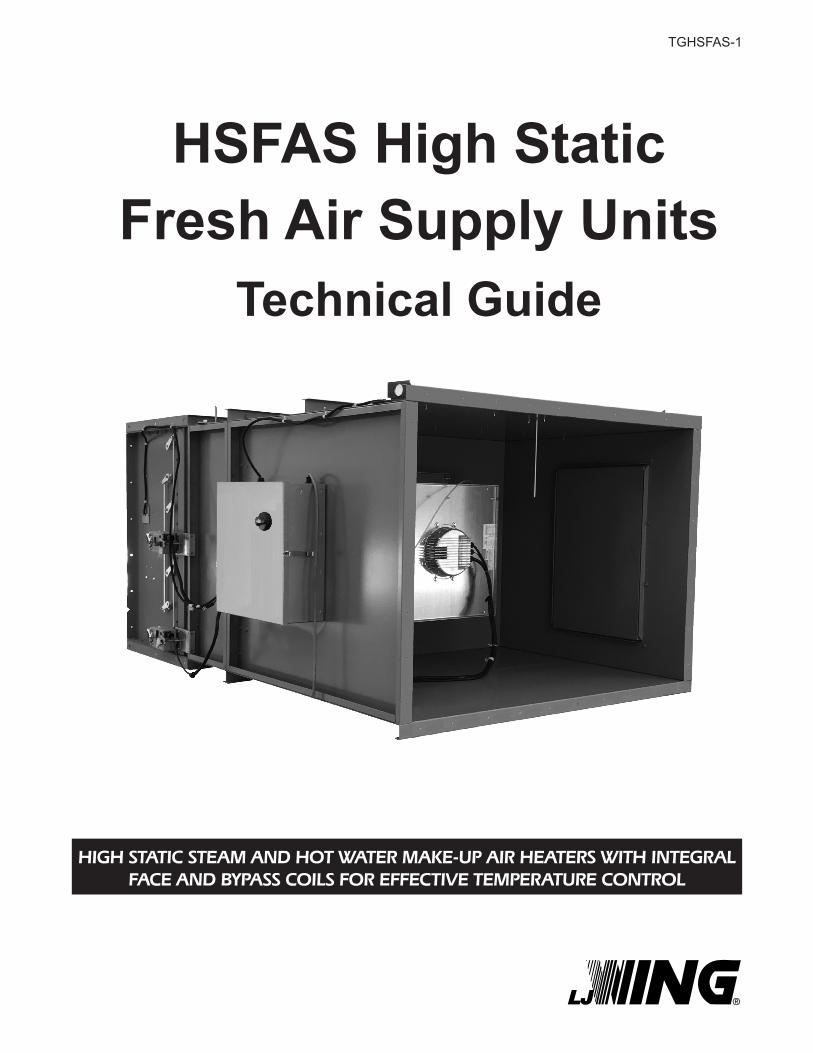
HSFAS High Static Fresh Air Supply Units
Technical Guide
HIGH STATIC STEAM AND HOT WATER MAKE-UP AIR HEATERS WITH INTEGRALFACE AND BYPASS COILS FOR EFFECTIVE TEMPERATURE CONTROL
TGHSFAS-1

2
Since 1875, the L.J. Wing Company has been a leader in providing innovative solutions for difficult HVAC problems. Wing HSFAS High Static Fresh Air Supply units provide heated make-up air for buildings. This technical guide will help you size, select and specify the proper HSFAS model, incorporating EC fan technology for high static applications, to satisfy your project’s make-up air heating requirements. If you have questions, please contact your local L.J. Wing representative; he will be glad to assist you.
4830 Transport Drive, Dallas, TX 75247 Tel. (214) 638-6010 www.ljwing.com
In the interest of product improvement, L.J. Wing reserves the right to make changes without notice.
TABLE OF CONTENTS
Make-Up Air Heating ..................................................3Model Number Description .........................................3Operation ....................................................................4Design and Construction ............................................5Performance and Selection .................................... 6-9Dimensions ..........................................................10-11Controls .............................................................. 12-15Electrical ...................................................................16Piping........................................................................17Typical Specification and Schedule ..........................18
2

3
MAKE-UP AIR HEATING
Why the HSFAS Unit is Needed
Make-up air is needed to replenish air being exhausted from buildings. Without sufficient fresh air, a negative pressure is created inside the building, starving the flow of air through the exhaust system and hindering its performance. Wing HSFAS High Static Fresh Air Supply units offer a solution to this problem by delivering a constant volume of fresh tempered air.
HSFAS Units maintain effective temperature control by using integral face and bypass coils with steam or hot water as the heating source. The integral face and bypass coil concept eliminates the need for modulating control valves.
Ten sizes of HSFAS Units with energy efficient EC (Electronically Commuted) fans are available to cover a range of airflows from 855 to 10,000 CFM with static pressure capabilities up to 2.5” W.C. total static pressure. The EC motor and direct drive plenum fan provide energy efficiency at all operating speeds, higher static capabilities, and are superior to standard induction motors in their wide operating range, quiet operation, and long lifespan. Design is available for horizontal air flow.
Horizontal Air Flow - Type HSFAS units are designed for installation in wall openings. Fresh air is drawn in through optional weatherproof hoods or wall louvers (with or without optional filters) and discharged through adjustable vanes to achieve the desired airflow pattern. Discharge vanes may be horizontal, vertical, or both.
Type HSFAS units are ideal for preheating make-up air for boiler rooms; for further information on this application, please request Application Manual AMCAP-1.
Model Number Description
Internal Heater LossHSFAS Size 13 17 19 22 24 25 27 30 33 36
Pressure Drop 0.17 0.21 0.21 0.17 0.31 0.19 0.29 0.26 0.27 0.26
Calculating Total Static Pressure (TSP)Duct StaticHeater LossFilters (0.25” W.C.)Mixing Dampers (0.13” W.C.)
TSP (Maximum 2.5” W.C.) =
4
OPERATION
Integral Face and Bypass Coil Operation
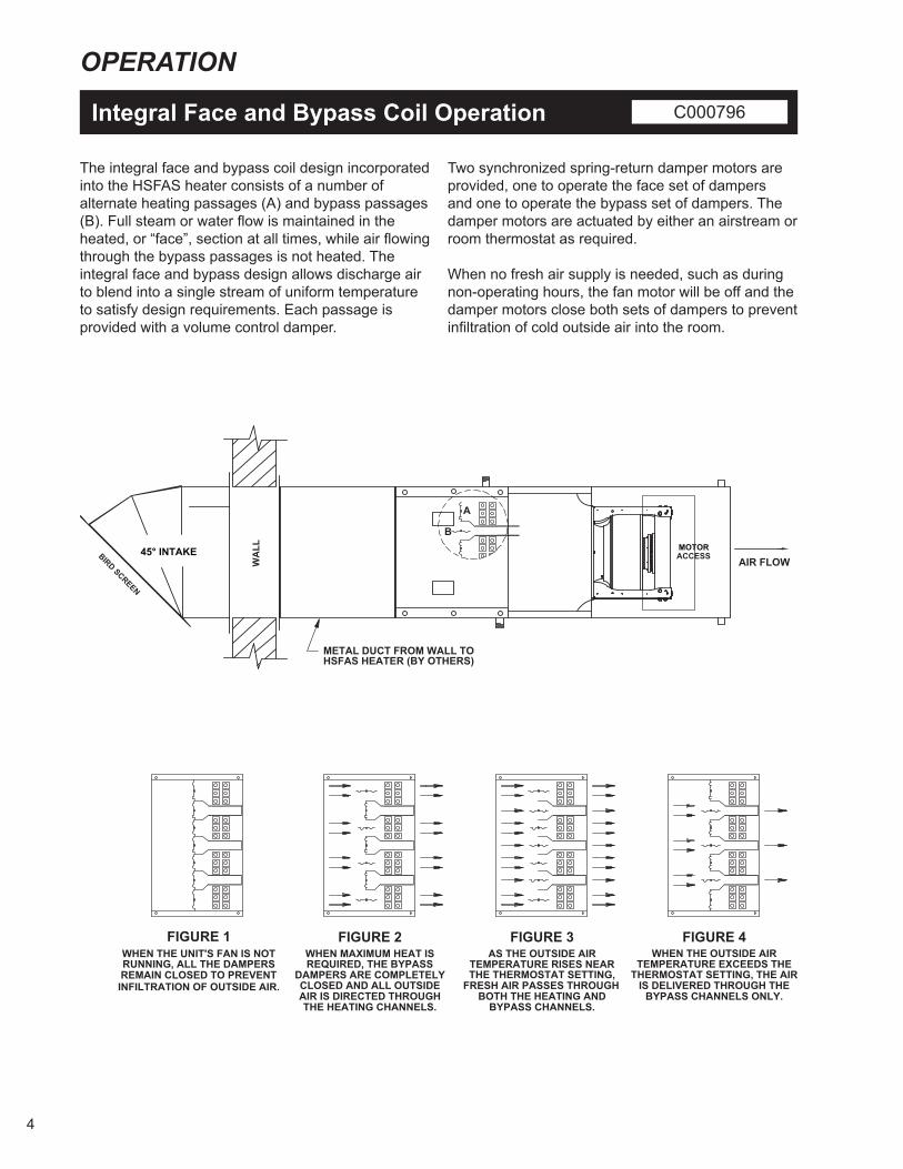
The integral face and bypass coil design incorporated into the HSFAS heater consists of a number of alternate heating passages (A) and bypass passages (B). Full steam or water flow is maintained in the heated, or “face”, section at all times, while air flowing through the bypass passages is not heated. The integral face and bypass design allows discharge air to blend into a single stream of uniform temperature to satisfy design requirements. Each passage is provided with a volume control damper.
Two synchronized spring-return damper motors are provided, one to operate the face set of dampers and one to operate the bypass set of dampers. The damper motors are actuated by either an airstream or room thermostat as required.
When no fresh air supply is needed, such as during non-operating hours, the fan motor will be off and the damper motors close both sets of dampers to prevent infiltration of cold outside air into the room.
C000796
MOTORACCESS
WA
LL
BIRD SCREEN
45° INTAKE
FIGURE 1WHEN THE UNIT'S FAN IS NOTRUNNING, ALL THE DAMPERSREMAIN CLOSED TO PREVENTINFILTRATION OF OUTSIDE AIR.
FIGURE 2WHEN MAXIMUM HEAT ISREQUIRED, THE BYPASS
DAMPERS ARE COMPLETELYCLOSED AND ALL OUTSIDE
FIGURE 3AS THE OUTSIDE AIR
TEMPERATURE RISES NEARTHE THERMOSTAT SETTING,
FRESH AIR PASSES THROUGH
FIGURE 4WHEN THE OUTSIDE AIR
TEMPERATURE EXCEEDS THETHERMOSTAT SETTING, THE AIR
IS DELIVERED THROUGH THEAIR IS DIRECTED THROUGHTHE HEATING CHANNELS.
BOTH THE HEATING ANDBYPASS CHANNELS.
BYPASS CHANNELS ONLY.
AIR FLOW
METAL DUCT FROM WALL TOHSFAS HEATER (BY OTHERS)
A
B

5
Heating ElementType: Fin and tube, extended surface type.Tubes: 3/8” O.D. copper, 0.028” thick wall for service to 200 psig and 400 degrees F. (Optional 90/10 cupronickel and steel are available for higher working pressures and temperatures).Fins: Smooth, rectangular aluminum fins, 0.010” thick; mechanically bonded to the tubes. (Optional: carbon steel fins).Headers: Schedule 40 steel, connected to tubes by a brazed joint.
Casing Assembly Material: 14 gauge galvanized steel. Attachment to heating elements: By heavy key plates welded to the headers. Tube ends are guided, spaced and secured against vibration by channel–shaped retainers.
Face and Bypass Dampers Material: 16 gauge galvanized steel. The heatercoil banks and by-pass passages are alternated for proper air proportioning.
DESIGN AND CONSTRUCTION
Construction Details
Motor and Sound Data
Fan Type: Plenum fan with motorized impeller.Material: Aluminum impellers, galvanized sheet steel inlet cone and support structure.
Motor Type: Electronically commutated (EC) motor.Electronics housing material: Die-Cast aluminum.
Finish Unpainted as standard. (Optional: Air-dried enamel paint).
HSFAS SIZE
MOTOR HP
FAN RPM
SOUND POWER
LEVEL - dBSINGLE PHASE THREE PHASE
200-240V 460V13 3/4 2 2-1/4 3,700 82.3 17 1-1/2 2 2 3,500 76.6 19 1-1/2 2 2-1/4 2,400 76.7 22 N/A 4-1/4 4 1,750 78.9 24 N/A 4-1/4 4 1,750 80.4 25 N/A 4-1/4 4 1,750 81.3 27 N/A 4-1/2 5 1,750 84.0 30 N/A 4 4-1/2 1,180 85.5 33 N/A N/A 8-1/4 1,450 81.6 36 N/A N/A 8-1/4 1,450 84.3
Notes: 1. Single-phase units through size 19, available in 230V.2. Single-phase and 3-phase units feature EC motorized impeller fans.
6
PERFORMANCE
Steam Units
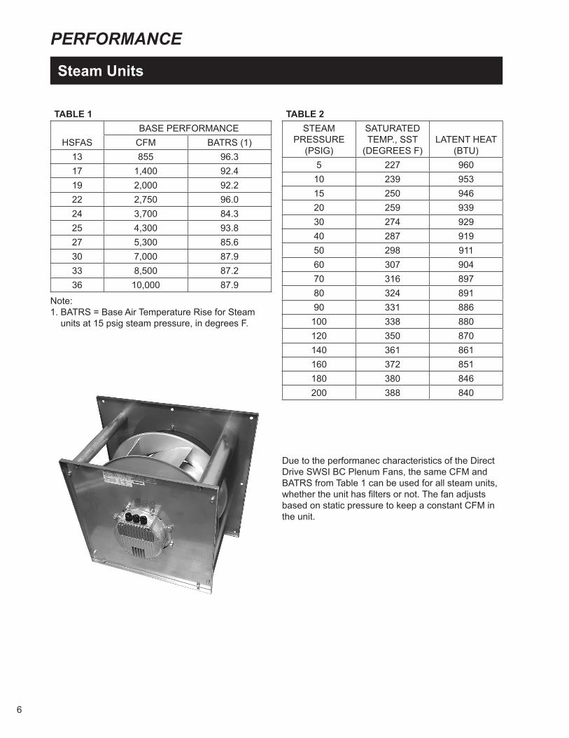
TABLE 1
HSFAS BASE PERFORMANCECFM BATRS (1)
13 855 96.3 17 1,400 92.4 19 2,000 92.2 22 2,750 96.0 24 3,700 84.3 25 4,300 93.8 27 5,300 85.6 30 7,000 87.9 33 8,500 87.2 36 10,000 87.9
Note: 1. BATRS = Base Air Temperature Rise for Steam units at 15 psig steam pressure, in degrees F.
TABLE 2STEAM
PRESSURE(PSIG)
SATURATEDTEMP., SST
(DEGREES F)LATENT HEAT
(BTU)5 227 960
10 239 95315 250 94620 259 93930 274 92940 287 91950 298 91160 307 90470 316 89780 324 89190 331 886
100 338 880120 350 870140 361 861160 372 851180 380 846200 388 840
Due to the performanec characteristics of the Direct Drive SWSI BC Plenum Fans, the same CFM and BATRS from Table 1 can be used for all steam units, whether the unit has filters or not. The fan adjusts based on static pressure to keep a constant CFM in the unit.
7
SELECTION
Steam Units
1. Select HSFAS Unit with or without filters to meet project make-up air requirements from Table 1.
2. Read the base air temperature rise for steam units, BATRS, from Table 1.
3. Calculate the air temperature rise correction factor, ATRS: ATRS = (SST-EAT)/250 where SST = Saturated steam temperature from Table 2 and EAT = Entering air temperature as given.
4. Calculate heat transfer, Q: Q = 1.085 x CFM x ATRS x BATRS where CFM = Airflow from Table 1.
5. Calculate the air temperature leaving the HSFAS unit, LAT: LAT = EAT + (BATRS x ATRS)
6. Calculate the condensate load, CL: CL = Q/LH where LH = Latent heat from Table 2.
Example: Select HSFAS unit without filters for 7,000 CFM of make-up air using 5 psig steam to heat outside air at –12 degrees F.
Solution:1. For 7,000 CFM, choose an HSFAS-30 from Table 1. 2. Also from Table 1, BATRS = 87.9 degrees F for
an HSFAS-30.3. From Table 2, SST = 227 degrees F, so: ATRS = (227 –(-12))/250 = 0.9564. Q = 1.085 x 7,000 x 87.9 x 0.956 = 638,200
BTUH.5. LAT = -12 + (87.9 x 0.956) = 72.0 degrees F6. From Table 2, LH = 960, so: CL= 638,200/960 = 664.8 lb/hr.

8
PERFORMANCE
Hot Water Units
TABLE 3
HSFAS BASE PERFORMANCE
GPMB (2) WPDB (3)CFM BATRW (1)13 855 71.7 13.5 3.7 17 1,400 67.8 14.8 4.4 19 2,000 67.6 17.6 5.0 22 2,750 71.4 23.5 6.9 24 3,700 60.1 23.5 6.9 25 4,300 69.2 35.0 10.0 27 5,300 61.3 35.0 10.0 30 7,000 63.4 49.0 5.8 33 8,500 62.8 58.0 7.7 36 10,000 63.4 70.0 9.4
TABLE 5: COIL CORRECTION FACTORS FOR GLYCOL / WATER SOLUTIONS
MASS PERCENTAGE
OF GLYCOL IN WATER SOLUTION
SOLUTION FREEZE POINT ATRG (1) WPDG (2)
WATER TEMPERATURE DROP CORRECTION FACTORS (WTDG)
FOR SOLUTION TEMPERATURES OF
150°F TO 250°F
FOR SOLUTION TEMPERATURES
ABOVE 250°FCOIL CORRECTION FACTORS FOR ETHYLENE GLYCOL30% ETHYLENE 6.7°F 0.92 1.18 1.11 (463.6) 1.03 (485.4)45% ETHYLENE -17.5°F 0.89 1.26 1.14 (445.3) 1.06 (471.7)50% ETHYLENE -28.9°F 0.84 1.31 1.17 (438.4) 1.08 (462.9)60% ETHYLENE -54.9°F 0.83 1.61 1.20 (422.6) 1.14 (438.6)70% ETHYLENE <-60.0°F 0.79 1.81 1.23 (404.5) 1.19 (420.2)COIL CORRECTION FACTORS FOR PROPYLENE GLYCOL30% PROPYLENE 9.2°F 0.96 1.30 1.05 (476.6) 1.01 (495.0)45% PROPYLENE -16.1°F 0.93 1.36 1.07 (458.7) 1.02 (490.2)50% PROPYLENE -28.3°F 0.88 1.38 1.09 (452.0) 1.03 (485.4)60% PROPYLENE -59.9°F 0.87 1.46 1.13 (434.1) 1.07 (467.3)70% PROPYLENE <-60.0°F 0.83 1.50 1.20 (413.3) 1.08 (462.9)
TABLE 4 WATER FLOW RATE/BASE
WATER FLOW RATE
ATRCORRECTION
FACTOR, ATRF
WPDCORRECTION
FACTOR, WPDF
1.5 1.040 2.251.2 1.020 1.441.0 1.000 1.000.8 0.965 0.640.6 0.910 0.360.5 0.860 0.26
Notes: 1. BATRW = Base air temperature rise for water units at 200 degrees F entering water temperature, in degrees F.2. GPMB = Base Water Flow Rate, in gallons per minute.3. WPDB = Base Water Pressure Drop, in feet H2O.
Notes: 1. ATRG = Air Temperature Correction Factor due to Glycol2. WPDG = Water Pressure Drop Correction Factor due to Glycol3. WTDG = Water Temperature Drop Correction Factor due to Glycol4. If 100% water is used (no glycol), all glycol-related correction factors will be 1.00.

9
SELECTION
Hot Water Units
1. Select HSFAS Unit with or without filters to meet project make-up air requirement from Table 3.
2. Read the base air temperature rise for water units, BATRW, from Table 3.
3. Calculate the air temperature rise correction factor, ATRW:
ATRW = (EWT- EAT)/200 where EWT= Entering water temperature as
given and EAT = Entering air temperature as given.
4. Using the given water flow rate, calculate the ratio to base water flow rate from Table 3.
5. Using the ratio of step 4, look up the air temperature rise correction factor due to gpm, ATRF, from Table 4.
6. Using the given glycol mixture, look up the Air Temperature Rise correction factor for glycol, ATRG, from Table 5.
7. Calculate the heat transfer, Q: Q = 1.085 x CFM x (BATRW x ATRW x ATRF x
ATRG) where CFM = Airflow from Table 3.8. Calculate the air temperature leaving the HSFAS
unit, LAT: LAT = EAT + (BATRW x ATRW x ATRF x ATRG)9. Read the base water pressure drop, WPDB, from
Table 3 for the unit selected.10. Read the water pressure drop correction factor
due to flow, WPDF, from Table 4 using the flow ratio of Step 4.
11. Read the water pressure drop correction factor due to glycol, WPDG, from Table 5 at the given glycol mixture.
12. Calculate the water pressure drop, WPD: WPD = WPDB x WPDF x WPDG13. Calculate the water temperature drop, WTD, Using the correction factor due to glycol from
Table 5: WTD = (Q x WTDG)/(500 x GPM)
Example: Select HSFAS unit without filters for 4,300 CFM of make-up air using 42.0 gpm of 210 degrees F water to heat outside air at 0 degrees F.
Solution:1. For 4,300 CFM, choose an HSFAS-25 from
Table 1.2. Also from table 1, BATRW = 69.2 degrees F for
an HSFAS-25.3. ATRW = (210-0))/200 = 1.054. From Table 3, base water flow rate = 35 gpm.
Water flow rate/base water flow rate = 42.0/35 = 1.20.
5. From Table 4 at water flow rate/ base water flow rate = 1.20: ATRF = 1.02.
6. Since there is no glycol used, ATRG = 1.00 from Table 5.
7. Q= 1.085 x 4,300 x (69.2 x 1.05 x 1.02 x 1.00) = 345,800 BTUH.
8. LAT = 0 + (69.2 x 1.05 x 1.02 x 1.00) = 74.1 degrees F.
9. From Table 3 for HSFAS-25: WPDB = 10.0 feet H20.
10. From Table 4 at a water flow ratio of 1.20: WPDF = 1.44.11. From Table 5 at 100% water: WPDG = 1.00.12. WPD = (10.0 x 1.44 x 1.00) = 14.4 ft. H20.13. From Table 5 at 100% water: WTDG = 1.00. WTD = (345,800 x 1.00)/(500 x 42.0) = 16.5
degrees F.
Glycol Example: Select the same HSFAS as above but with 45% Propylene Glycol, 55% Water Solution.
Solution: Same steps 1-5 as above.6. From Table 5 at a mixture of 45% propylene
glycol, ATRG = 0.93.7. Q= 1.085 x 4,300 x (69.2 x 1.05 x 1.02 x 0.93) =
321,600 BTUH.8. LAT = 0 + (69.2 x 1.05 x 1.02 x 0.93) = 68.9
degrees F. Same steps 9-10 as above.11. From Table 5 at 45% propylene glycol: WPDG =
1.36.12. WPD = (10.0 x 1.44 x 1.36) = 19.6 ft. H20.13. From Table 5 at 45% propylene glycol between
150°F and 250°F: WTDG = 1.14. WTD = (321,600 x 1.14)/(500 x 42.0) = 17.5
degrees F.
TABLE 5: COIL CORRECTION FACTORS FOR GLYCOL / WATER SOLUTIONS
MASS PERCENTAGE
OF GLYCOL IN WATER SOLUTION
SOLUTION FREEZE POINT ATRG (1) WPDG (2)
WATER TEMPERATURE DROP CORRECTION FACTORS (WTDG)
FOR SOLUTION TEMPERATURES OF
150°F TO 250°F
FOR SOLUTION TEMPERATURES
ABOVE 250°FCOIL CORRECTION FACTORS FOR ETHYLENE GLYCOL30% ETHYLENE 6.7°F 0.92 1.18 1.11 (463.6) 1.03 (485.4)45% ETHYLENE -17.5°F 0.89 1.26 1.14 (445.3) 1.06 (471.7)50% ETHYLENE -28.9°F 0.84 1.31 1.17 (438.4) 1.08 (462.9)60% ETHYLENE -54.9°F 0.83 1.61 1.20 (422.6) 1.14 (438.6)70% ETHYLENE <-60.0°F 0.79 1.81 1.23 (404.5) 1.19 (420.2)COIL CORRECTION FACTORS FOR PROPYLENE GLYCOL30% PROPYLENE 9.2°F 0.96 1.30 1.05 (476.6) 1.01 (495.0)45% PROPYLENE -16.1°F 0.93 1.36 1.07 (458.7) 1.02 (490.2)50% PROPYLENE -28.3°F 0.88 1.38 1.09 (452.0) 1.03 (485.4)60% PROPYLENE -59.9°F 0.87 1.46 1.13 (434.1) 1.07 (467.3)70% PROPYLENE <-60.0°F 0.83 1.50 1.20 (413.3) 1.08 (462.9)
TABLE 4 WATER FLOW RATE/BASE
WATER FLOW RATE
ATRCORRECTION
FACTOR, ATRF
WPDCORRECTION
FACTOR, WPDF
1.5 1.040 2.251.2 1.020 1.441.0 1.000 1.000.8 0.965 0.640.6 0.910 0.360.5 0.860 0.26

10
DIMENSIONS
Horizontal HSFAS UnitS C000795
01/08/16 C000795
A
B
C
EC PLENUM FANS
MPT PIPEG
E
H 10"
DA
MPE
R A
CTU
ATO
RS
F
CONNECTIONS
HO
RIZ
ON
TAL
I
HO
RIZ
ON
TAL
AN
D V
ERTI
CA
L
J
VER
TIC
AL
I
BIRD SCREEN
45° INTAKE
K
FILTER BOX
L
FILTERACCESSDOOR
WALL INTAKE HOOD
SIZES 13 THRU 36
C = STANDARD HEATER CASING DEPTH
DISCHARGE LOUVER ASSEMBLY FURNISHED
MAX
HEADER LOCATIONON SIZES 30 THRU 36
AND MOUNTED ON THE UNIT AT THE FACTORY
D M
HORIZONTAL BASE UNITRIGHT SIDE VIEW
END VIEW
INTAKE SECTION ON BOTTOM SIDE, "D" DIMENSION SHOULD BE A REMOVABLE PANELCONTROL BOX ENCLOSURE ON SMALLER UNITS (FAS 13-19) WILL EXTEND BEYOND UNIT HEIGHT
HFAS
DIMENSIONS (INCHES) WEIGHTS (LBS)
A B C D E F G H I J K L M B1 B2 WI FB
13 19 3/4 19 3/4 17 12 1/2 3 9/32 1 5/32 1 1/2 2 9/16 3 5/16 6 1/2 19 1/16 26 1/2 22 142 153 30 40
17 22 3/4 22 3/4 17 12 1/2 3 7/16 1 15/16 1 1/2 2 9/16 3 5/16 6 1/2 21 7/32 21 22 166 178 40 45
19 27 3/4 27 3/4 21 12 1/2 3 25/32 1 15/32 1 1/2 2 3/4 3 5/16 6 1/2 24 3/4 28 30 245 262 55 65
22 32 3/4 32 3/4 21 12 1/2 3 27/32 1 13/32 1 1/2 2 3/4 3 5/16 6 1/2 28 9/32 31 34 330 354 70 80
24 32 3/4 32 3/4 21 12 1/2 3 27/32 1 13/32 1 1/2 2 3/4 3 5/16 6 1/2 28 9/32 31 34 392 415 70 80
25 39 1/8 39 1/8 22 12 1/2 4 5/16 1 11/16 2 3 7/16 4 5/16 8 1/2 32 3/32 37 40 397 431 95 120
27 39 1/8 39 1/8 22 12 1/2 4 5/16 1 11/16 2 3 7/16 4 5/16 8 1/2 32 3/32 37 40 402 436 95 120
30 50 1/8 45 1/8 28 12 1/2 5 3/8 2 2 1/2 25 1/16 4 5/16 8 1/2 35 5/16 37 44 703 754 125 150
33 60 3/4 45 1/8 28 12 1/2 5 3/8 2 2 1/2 30 3/8 4 5/16 8 1/2 36 5/16 37 48 1072 1132 150 180
36 60 3/4 49 3/4 32 1/8 12 1/2 8 1/4 4 1/4 3 30 3/8 4 5/16 8 1/2 39 19/32 37 48 1169 1234 165 200
Notes:
1. All dimensions in inches.2. All weights in pounds.
3. Weight nomenclature: B1 = Base Horizontal Unit with Horizontal or Vertical blade discharge;
B2 = Base HorizontalUnit with Horizontal and Vertical blade discharge; WI = Wall Intake Hood; FB = Filter Box.
O/A S/A
HSFASDIMENSIONS (INCHES) WEIGHTS (LBS)
A B C D E F G H I J K L M B1 B2 WI FB13 19 3/4 19 3/4 17 12 1/2 3 9/32 1 5/32 1 1/2 2 9/16 3 5/16 6 1/2 19 1/16 26 1/2 22 141.7 152.8 30 4017 22 3/4 22 3/4 17 12 1/2 3 7/16 1 15/16 1 1/2 2 9/16 3 5/16 6 1/2 21 7/32 21 22 166.3 177.9 40 4519 27 3/4 27 3/4 21 12 1/2 3 25/32 1 15/32 1 1/2 2 3/4 3 5/16 6 1/2 24 3/4 28 30 244.6 261.7 55 6522 32 3/4 32 3/4 21 12 1/2 3 27/32 1 13/32 1 1/2 2 3/4 3 5/16 6 1/2 28 9/32 31 34 330.2 353.9 70 8024 32 3/4 32 3/4 21 12 1/2 3 27/32 1 13/32 1 1/2 2 3/4 3 5/16 6 1/2 28 9/32 31 34 391.6 415.3 70 8025 39 1/8 39 1/8 22 12 1/2 4 5/16 1 11/16 2 3 7/16 4 5/16 8 1/2 32 3/32 37 40 397.2 431.2 95 12027 39 1/8 39 1/8 22 12 1/2 4 5/16 1 11/16 2 3 7/16 4 5/16 8 1/2 32 3/32 37 40 401.9 435.9 95 12030 50 1/8 45 1/8 28 12 1/2 5 3/8 2 2 1/2 25 1/16 4 5/16 8 1/2 35 5/16 42 44 702.6 753.6 125 15033 60 3/4 45 1/8 28 12 1/2 5 3/8 2 2 1/2 30 3/8 4 5/16 8 1/2 36 5/16 50 48 1071.6 1132.3 150 18036 60 3/4 49 3/4 32 1/8 12 1/2 8 1/4 4 1/4 3 30 3/8 4 5/16 8 1/2 39 19/32 44 48 1168.8 1234.3 165 200
Note: 1. Weight nomenclature: B1 = Base Horizontal Unit with Horizontal or Vertical blade discharge; B2 = Base Horizontal Unit with Horizontal and Vertical blade discharge; WI = Wall Intake Hood; FB = Filter Box.

11
DIMENSIONS
Mixing Box C000794
09/19/16 C000794
HSFAS MIXING BOX
B
A
D
MIXING BOX
ACCESSPANEL
E
RETURN AIROPENING ON
BOTH TOP AND
OUTSIDE AIROPENING
BOTTOM OFMIXING BOX
C
FLOWAIR
HSFASDIMENSIONS (INCHES) WEIGHTS (LBS)
A B C D E MB13 19 3/4 19 3/4 8 1/2 30 1 1/2 11517 22 3/4 22 3/4 8 1/2 33 1 1/2 14019 27 3/4 27 3/4 8 1/2 33 1 1/2 18522 32 3/4 32 3/4 8 1/2 30 1 1/2 19524 32 3/4 32 3/4 8 1/2 30 1 1/2 19525 39 1/8 39 1/8 8 34 2 25027 39 1/8 39 1/8 8 34 2 25030 50 1/8 45 1/8 8 34 2 33033 60 3/4 45 1/8 8 34 2 34036 60 3/4 49 3/4 8 34 2 355
Note: 1. Weight nomenclature: MB = Mixing Box
12
CONTROL SYSTEMS
Controls
Methods of ControlThe HSFAS is available with either of two methods of control: The first is a basic HSFAS with Airstream or Room with Low Limit that uses a Neptronic controller for fan control. Both methods control the discharge temperature of the unit by modulating the face and bypass dampers. With Airstream control, the controller is mounted on the unit and has a single sensing element located in the discharge airstream. Room with Low Limit control uses the Airstream controller as its low limit and adds a room thermostat as the primary control.
The second offering is a HSFAS with DDC controls. The methods of control include MDT Touch and MRT Touch control system.
MDT Touch Control SystemThe MDT Touch Control System includes a discharge air sensor mounted in the unit with remote mounted equipment touch touchscreen controller to set discharge temperature, operating schedules, optional damper control setpoints, and fan control which is one of either manual control, building pressure control, piezometer ring control or building pressure with piezometer control. Service information, operating feedback and alarm status can also be monitored.
MRT Touch Control SystemThe MRT Touch Control System includes a discharge air sensor mounted in unit discharge with remote mounted Equipment Touch Touchscreen controller to set space temperature, operating schedules, optional damper control setpoints, and fan control which is one of either manual control, building pressure control, piezometer ring control or building pressure with piezometer control. Service information, operating feedback and alarm status can also be monitored. Also includes a ZS-Standard room sensor.
Electric ActuatorsBoth methods of control are available in only electric versions. The standard electric version uses direct-coupled 24 volt damper actuators with compatible controllers.
Controller SetpointsThe HSFAS heater is a make-up air system and, as such, the delivered air temperature should be at or near that of the room ambient temperature. On the basic HSFAS unit with Room with Low Limit
control, this insures that if the Room thermostat is satisfied, the Low Limit controller will not allow the unit discharge to fall below the desired temperature. Without this, or if the Low Limit were set well below the Room, unheated air could be introduced into the room, driving the ambient temperature down and requiring the unit to bring it back up. The Room with Low Limit Control prevents this unwanted temperature cycling.
This principle applies to the DDC Controls as well with all the logic built into the program and downloaded on to the controller.
Sequence of OperationWhen maximum temperature rise is required, the face dampers are fully open to the heating sections while the bypass dampers are fully closed. With electric actuators, as the discharge temperature approaches the controller set point, the bypass dampers will begin to open. Once the bypass dampers are fully open, if even less temperature rise is required, the face dampers will begin to close.
Shutoff FeatureWhen the unit is shut down, both the face and bypass dampers close to prevent the infiltration of cold outside air. There is no need for a separate motorized shutoff damper.
Additional Control OptionsIncluded among the additional control options are:
• Freeze stat – The freeze stat will either stop the fan from starting or automatically cycle the unit off should the coil temperature drop below the freeze stat setpoint for any period of time. The freeze stat itself is a separate thermostat with the capillary section strung across the coil face.
• Fan Cut-Off Thermostat - Uses a single sensing bulb to shut down the unit upon sensing a temperature that could potentially lead to a frozen tube or coil. This option is optional for the basic HSFAS unit and standard for HSFAS units with DDC controls.
• Discharge Dampers – Can be installed on the leaving side of the face sections to minimize temperature override.
• Clogged Filter – The clogged filter switch automatically notifies the user of a dirty filter condition. A clogged filter notification will either be a light indicator on a standard HSFAS unit or it will appear on the equipment touch for HSFAS units with DDC controls.

13
CONTROL SYSTEMS
Neptronic Control System C000800
Application: Includes:
Neptronic controller allowing fan control and discharge temperature control. Room with Low Limit adds a room thermostat for primary control.
Discharge air sensor mounted in the unit with unit mounted Neptronic Controller to control the fan and dampers. If Room with Low Limit is selected, a room thermostat is also included.
1
2
3
1. Neptronic Controller2. EC Motorized Impeller
3. Face/Bypass Actuators4. Static Pressure Probes
COMPONENT I.D.
3 4
4
5
5. Piezometer Ring
14
CONTROL SYSTEMS
MDT Touch Control System C000791
Application: Includes:
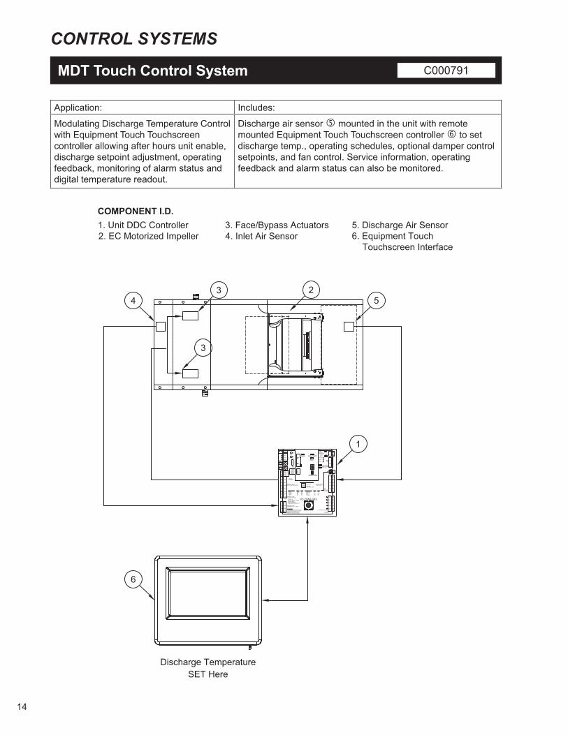
Modulating Discharge Temperature Control with Equipment Touch Touchscreen controller allowing after hours unit enable, discharge setpoint adjustment, operating feedback, monitoring of alarm status and digital temperature readout.
Discharge air sensor mounted in the unit with remote mounted Equipment Touch Touchscreen controller to set discharge temp., operating schedules, optional damper control setpoints, and fan control. Service information, operating feedback and alarm status can also be monitored.
NET +
NET -
SHIELD
SENSE+12VRNCT+RNCT-GND
GNDRNET+RNET-+12V
RN
ET
0
98
7654
3 2 1
LOCAL ACCESS
GND
INPUTS 1&205V,THERM OR DRY
INPUTS 3 & 4THERM OR DRY
GND
IN-5
IN-6
LED
INPUTS 5 & 6THERM DRY or LStat
CLASS 224 Vac. 50/60 CYCLE2Ova, 0.83AUSE COPPERCONDUCTORS ONLY.
CAUTION:To Reduce The Risk of Fire or or Electrical Shock, Do NotInterconnect Outputs of Different Class 2 Circuits
I/O ZONE 583
BT485Rx
Tx
+-
Batt
CR2032
Communications Selection
One
sTe
nsC
omm
Gnd
Hot
Format LStat Rnet
Short PinsL StatIN-5 24 V ac
Power
Run
Error
IN-7
+3V
Gnd
IN-8
Pot.Only
Thermistor/Dry Contact0-5 vdc
On4321
EIA-485
BACnetover ARC 156
Comm SelectorDIP Switch
BAUD Rates SW1 SW2 PROTOCOLS SW1 SW2950019.2 K38.4K76.8 K
OFFOffOnOn
OffOnOffOn
BACnetMS/TPN2Modbus
Off
OnOff
Off
OffOn
Gnd
A0-3
Gnd
A0-2
A0-1
Gnd
DO-2
DO-1BUSPower for D.O.s
0-10vdc5ma Max.
BACnet
FormatJumper
LStat / Rnet PortSelector Jumper
Gain 1Jumper
CommunicationSelection Jumper
DO-3
DO-4
DO-5
GND
IN-4
IN-2
IN-3
IN-1
GND +
-
+
-
+
-
}
AO:
GND
0
98
76532 1
4
54
1
2
3
6
Discharge TemperatureSET Here
1. Unit DDC Controller2. EC Motorized Impeller
3. Face/Bypass Actuators4. Inlet Air Sensor
5. Discharge Air Sensor6. Equipment Touch Touchscreen Interface
COMPONENT I.D.
3

15
CONTROL SYSTEMS
MRT Touch Control System C000792
Application: Includes:
Modulating Room Temperature Control with Equipment Touch Touchscreen controller allowing after hours unit enable, room setpoint adjustment, operating feedback, monitoring of alarm status and digital temperature readout with ZS-std room sensor.
Discharge air sensor mounted in the unit with remote mounted Equipment Touch Touchscreen controller to set space temp., operating schedules, optional damper control setpoints, and fan control. Service information, operating feedback and alarm status can also be monitored. Also includes a ZS-std room sensor .
NET +
NET -
SHIELD
SENSE+12VRNCT+RNCT-GND
GNDRNET+RNET-+12V
RN
ET
0
98
7654
3 2 1
LOCAL ACCESS
GND
INPUTS 1&205V,THERM OR DRY
INPUTS 3 & 4THERM OR DRY
GND
IN-5
IN-6
LED
INPUTS 5 & 6THERM DRY or LStat
CLASS 224 Vac. 50/60 CYCLE2Ova, 0.83AUSE COPPERCONDUCTORS ONLY.
CAUTION:To Reduce The Risk of Fire or or Electrical Shock, Do NotInterconnect Outputs of Different Class 2 Circuits
I/O ZONE 583
BT485Rx
Tx
+-
Batt
CR2032
Communications Selection
One
sTe
nsC
omm
Gnd
Hot
Format LStat Rnet
Short PinsL StatIN-5 24 V ac
Power
Run
Error
IN-7
+3V
Gnd
IN-8
Pot.Only
Thermistor/Dry Contact0-5 vdc
On4321
EIA-485
BACnetover ARC 156
Comm SelectorDIP Switch
BAUD Rates SW1 SW2 PROTOCOLS SW1 SW2950019.2 K38.4K76.8 K
OFFOffOnOn
OffOnOffOn
BACnetMS/TPN2Modbus
Off
OnOff
Off
OffOn
Gnd
A0-3
Gnd
A0-2
A0-1
Gnd
DO-2
DO-1BUSPower for D.O.s
0-10vdc5ma Max.
BACnet
FormatJumper
LStat / Rnet PortSelector Jumper
Gain 1Jumper
CommunicationSelection Jumper
DO-3
DO-4
DO-5
GND
IN-4
IN-2
IN-3
IN-1
GND +
-
+
-
+
-
}
AO:
GND
0
98
76532 1
454
1
2
3
7
Discharge TemperatureSET Here
1. Unit DDC Controller2. EC Motorized Impeller
3. Face/Bypass Actuators4. Inlet Air Sensor
5. Discharge Air Sensor6. Room Thermostat
COMPONENT I.D.
6
Space TemperatureSENSED Here
7. Equipment Touch Touchscreen Interface
3
16
ELECTRICAL
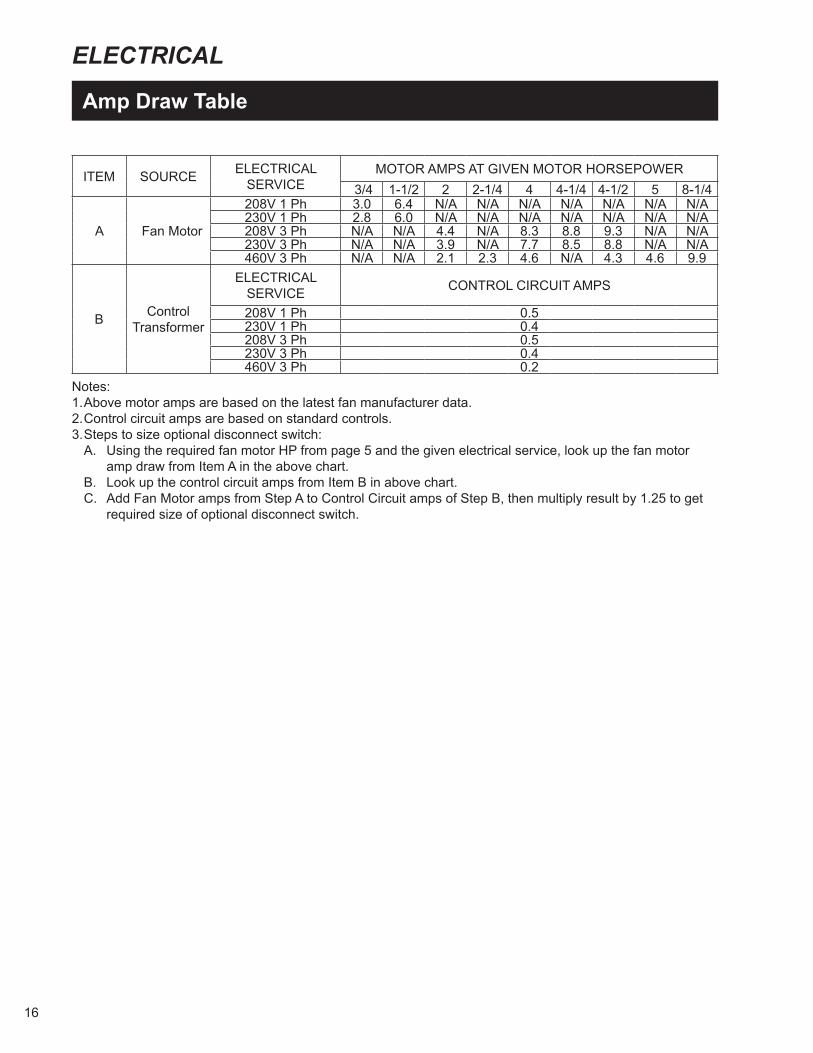
Amp Draw Table
ITEM SOURCE ELECTRICALSERVICE
MOTOR AMPS AT GIVEN MOTOR HORSEPOWER 3/4 1-1/2 2 2-1/4 4 4-1/4 4-1/2 5 8-1/4
A Fan Motor
208V 1 Ph 3.0 6.4 N/A N/A N/A N/A N/A N/A N/A230V 1 Ph 2.8 6.0 N/A N/A N/A N/A N/A N/A N/A208V 3 Ph N/A N/A 4.4 N/A 8.3 8.8 9.3 N/A N/A230V 3 Ph N/A N/A 3.9 N/A 7.7 8.5 8.8 N/A N/A460V 3 Ph N/A N/A 2.1 2.3 4.6 N/A 4.3 4.6 9.9
B Control Transformer
ELECTRICALSERVICE CONTROL CIRCUIT AMPS
208V 1 Ph 0.5230V 1 Ph 0.4208V 3 Ph 0.5230V 3 Ph 0.4460V 3 Ph 0.2
Notes: 1. Above motor amps are based on the latest fan manufacturer data.2. Control circuit amps are based on standard controls.3. Steps to size optional disconnect switch:
A. Using the required fan motor HP from page 5 and the given electrical service, look up the fan motor amp draw from Item A in the above chart.
B. Look up the control circuit amps from Item B in above chart.C. Add Fan Motor amps from Step A to Control Circuit amps of Step B, then multiply result by 1.25 to get
required size of optional disconnect switch.

17
PIPING
Steam and Hot Water Systems C000799
T
61
4 9 18
5 1
3 1
7
12112
111
12"
6"
STEAM PIPING LEGEND
1. GLOBE OR GATE VALVE
(FOR GRAVITY ATMOSPHERIC RETURN SYSTEMS)
2. OPTIONAL MOTORIZED SHUT-OFF VALVE3. BY-PASS TO ALLOW SERVICING OF MOTORIZED VALVE.
BYPASS LINE TO BE THE SAME SIZE AS MOTORIZED VALVE.4. INVERTED BUCKET OR COMBINATION FLOAT AND
THERMOSTATIC TRAP WITH VENT.5. BY-PASS TO PERMIT SERVICING OF TRAP. BY-PASS TO
BE ONE PIPE SIZE LARGER THAN TRAP ORIFICE.
7. STEAM SUPPLY MAIN.8. CONDENSATE RETURN MAIN.9. 15° SWING CHECK VALVE.
10. 1/2" SPRING LOADED VACUUM BREAKERVENTED TO ATMOSPHERE.
11. STEAM STRAINER WITH BLOW-DOWN VALVE.12. 1/2" DRAIN VALVE. TO BE OPENED WHEN GLOBE
OR GATE SHUTOFF VALVE IS CLOSED.6. DIRT POCKET AND DRIP LEG. TO BE THE SAME SIZE
AS THE HEATER CONDENSATE RETURN LINE.
HOT WATER PIPING LEGEND
1. GLOBE OR GATE VALVE2. AUTOMATIC AIR VENT
4. WATER FLOW CONTROL VALVE5. HOT WATER SUPPLY LINE
3. COIL DRAIN VALVE 6. HOT WATER RETURN LINE
3
4
5
216
10

SPECIFICATIONS AND SCHEDULE
Typical Specification
GeneralFurnish a factory-assembled HSFAS High Static Fresh Air Supply unit as manufactured by L.J. Wing, Dallas, TX, to heat outside air. Performance shall be as shown in the schedule. Unit shall be capable of maintaining discharge air temperature regardless of fluctuations in inlet air temperature. Each unit shall consist of a heater section containing an integral face and bypass coil consisting of built-in multiple alternate finned heating elements and bypasses. Separate dampers shall control the airflow through these face and bypass sections. Each set of dampers shall be interlocked and controlled by a separate electric damper motor as scheduled. Finned heating elements shall be fabricated of seamless return bend type 3/8” o.d. copper (Optional: 90/10 cupronickel or steel) tubes with rectangular 0.010” thick aluminum (Optional: steel) fins. Each tube shall be secured to the headers by a brazed joint. The opposite end of the tubes shall be secured by channel–shaped retainers that permit expansion and contraction. Finned elements shall be factory tested with 200 psig steam and 500 psig hydrostatic pressure. Unit shall have an EC fan with motorized impeller with characteristics as scheduled. Casing and discharge shall be constructed of galvannealed sheet metal.
ControlsUnit shall be furnished with ________________ (indicate either “Airstream Control with a thermostat to provide a constant discharge temperature regardless of inlet air temperature fluctuations”, or “Room with Low Limit Control having a room thermostat and overriding low limit thermostat to prevent the unit’s discharge temperature from falling below the desired minimum.”)
Discharge – Horizontal UnitsUnit shall have a discharge consisting of _______________ (indicate either “horizontal vanes for maximum horizontal airflow projection”; “vertical vanes for maximum airflow spread”; or “horizontal and vertical vanes for adjustable airflow projection and spread”). Discharge shall be attached to and supported by flanged brackets bolted to outlet of the unit for easy vane positioning.
Intake Hood (optional)Unit shall be furnished with an intake hood fashioned of heavy gauge sheet steel with 45 angular degree overhang and turned-up flange to prevent water from entering the unit. Intake shall be covered with bird screen to keep out animals and debris.
Filter Box (optional)Unit shall be equipped with a filter box fabricated of heavy gauge sheet steel, complete with __________ (indicate “throwaway” or “cleanable”) filters.
Painted Finish (optional)Unit casing and discharge shall be painted inside and out with an air-dried alkyd enamel finish.
Typical Schedule
ModelNo.
Airflow Rate
(SCFM)
Entering Air Temp.
(°F)
Leaving Air Temp.
(°F)
Steam Pressure
(PSIG)
Condensate Load
(lbm/hr)
External S.P.
(inches W.C.)
Electrical Service
(volt/ph./Hz)
Motor Horsepower
(HP)HSFAS-30-HV 7,000 -12 72 5 664.8 2 208/3/60 4.5

19

4830 Transport Drive, Dallas, TX 75247 Tel. (214) 638-6010
www.ljwing.comPrinted in USACopyright USA, 2017