Embed Size (px)
Citation preview
50
HS5E-K Interlock Switches with Key
Ratings
Contact RatingRated Insulation Voltage (Ui) (Note 1) 250V
Rated Thermal Current (Ith)
Operating temperature:–25°C to 60°C: 2 .5A max . 60°C to 65°C: 1 .5A max . 65°C to 70°C: 1 .0A max .
Rated Voltage (Ue) 30V 125V 250V
Rated Current (Ie) (Note 2)
ACResistive Load (AC-12) − 2 .5A 1 .5A
Inductive Load (AC-15) − 1 .5A 0 .75A
DCResistive Load (DC-12) 2 .5A 1 .1A 0 .55A
Inductive Load (DC-15) 2 .3A 0 .55A 0 .27A
Minimum applicable load (reference value) = 3V AC/DC, 5 mA (Applicable range may vary with operating conditions and load types .)
Approved ratings
TÜVAC-15 250V/0.75ADC-13 125V/0.22ADC-13 30V/2.3A
UL/c-UL AC 125V/1.5A Pilot DutyDC 125V/0.22A Pilot Duty
Key SpecificationsOperating Method 2-position maintained
Mechanical Durability 100,000 operations minimum
Insertion/Removal Durability 10,000 operations minimum
Operator Strength 1 .0 N·m minimum
Direct Opening Force 0 .6 N·m minimum
Direct Opening Angle 60° minimum
Part No. DevelopmentH S 5 E - K VA 0 L 0 3 - 2 A 5 0 1
VA:VD:
Circuit Code
Pilot Light 0: None
Main Circuit
Door Monitor Circuit
Lock Monitor Circuit
1NC, 1NO2NC
——
1NC, 1NO2NC
Rear Unlocking Button L: With Blank: Without
Cable Length 03: 3m 05: 5m
Key removal specificationsA: Removable in
all positionsB: Removable at UNLOCK C: Removable at LOCK
Key number Blank: Standard Key number (500) or 501 to 515
Operator position 2: 2-position
General Specifications
Applicable Standards
ISO14119, IEC60947-5-1EN60947-5-1 (TÜV approved)EN1088, GS-ET-19 (TÜV approved)UL508 (UL recognized)CSA C22.2 No. 14 (c-UL recognized)IEC60204-1/EN60204-1 (applicable standards for use)
Operating Temperature -25 to +70°C (No freezing)
Relative Humidity 45 to 85% (No condensation)
Storage Temperature -40 to +80°C (No freezing)
Pollution Degree 3Impulse Withstand Voltage 2.5 kV
Insulation Resistance(500V DC megger)
Between live and dead metal parts: 100 MΩ minimum (500V DC megger)Between live metal part and ground: 100 MΩ minimum (500V DC megger)Between live metal parts: 100 MΩ minimum (500V DC megger)Between terminals of the same pole: 100 MΩ minimum
Electric Shock Class Class II (IEC61140)
Degree of Protection IP65 (IEC60529)
Shock Resistance Operating extremes: 100 m/s2
Damage limits: 1,000 m/s2
Vibration Resistance Operating extremes: 10 to 55 Hz, amplitude 0.35 mmDamage limits: 30 Hz, amplitude 1.5 mm
Actuator Operating Speed 0.05 to 1.0 m/s
Direct Opening TravelActuator HS9Z-A51: 11 mm minimumActuator HS9Z-A51A/A52/A52A/A53/A55: 12 mm minimum
Direct Opening Force 80N minimumActuator Retention Force (Note 1) 1,400N minimum (GS-ET-19)
Operating Frequency 900 operations per hourRear Unlocking Button Mechanical Durability
3,000 operations minimum (HS5E-KL)
Mechanical Durability 1,000,000 operations minimum (GS-ET-19)
Electrical Durability100,000 operations minimum (AC-12, 250V, 1A)1,000,000 operations minimum (24V AC/DC, 100 mA)(Operating frequency: 900 operations per hour)
Performance between 41 and 42 when head is removed
Mechanical durability: 10 operations minimumInsulation resistance: 100 MΩ (initial value)Withstand voltage: 1,000V for 1 minute (initial value)
Conditional Short-circuit Current 50A (250V) (Note 2)
Cable UL2464, No. 22 AWG(12-core, 0.3 mm2 or equivalent/core)
Cable Diameter ø7.6 mm
Weight (approx.) 510g (3m cable), 680g (5m cable)
Note 1: See page 54 for actuator retention force .Note 2: Use 250V/10A fast-blow fuse for short-circuit protection .
New interlock switches that can be locked and unlocked with a key. • Head removal detection circuitry . • High-security pin tumbler key is used . Sixteen types of key numbers are available . • Available with rear unlocking button for emergency escape . • Accessory available for aluminum frame mounting . • The locking strength is 1400N minimum . (GS-ET-19) • The head orientation can be rotated, allowing 8 different actuator entries . • Metal actuator entry slot ensures high durability . • Actuator with rubber bushings alleviates the impact of the actuator entry slot . • Environmentally-friendly . RoHs directive compliant . • Compact body: 35 × 40 × 146 mm
Right-angle Actuator (SUS304)
Straight Actuator
Right-angle Actuator w/rubber bushings
Angle Adjustable Actuator (vertical)
51
HS5E-K Interlock Switches with Key
LD6A Series SignaLight
XW Series Emergency Stop Switch
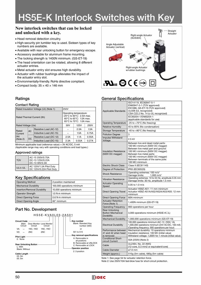
Maintenance Mode Change
HW Series Key Selector Switch (Pin Tumbler)
Mode Change Door Unlocked (safety output OFF)
Hazards of the system and robot are isolated by the safety guard . When a worker needs to work inside the hazardous area for maintenance, the worker stops the machine using the key to change modes (1), unlock the guard using the key, then remove the key to bring inside the safety guard (2) . The worker can switch operation modes and unlock the safety guard using a single key . Furthermore, when the key is taken inside the hazardous area, the guard cannot be locked and the system cannot be turned on . This enables the worker to work safely in the hazardous area .
Door Handle Actuator
HS5E-KKey Interlock Switch
+Door Handle Actuator
Single Key!
Head removal detection circuitry is employed in the HS5E-K . With this innovative function, the monitor circuit (41-42) turns off when the head is removed from the switch, such as when removing the head to change the head direction (applicable with all models of HS5E-K) .With the head installed on the switch, monitor circuits 41-42 and 51-52 operate in synchronization while the key locks/unlocks the actuator . When the head is removed, 41-42 turns off and 51-52 turns on . This disagreement is detected by the head removal detection function .
Head Removal Detection Circuitry (patented)
Actuator unlocked Actuator locked
Monitor circuit (41-42) with
head removal detection function
Head removed
Actuator unlocked
Actuator locked
Head removed
Monitor Circuit(NC)
424151 52
Monitor Circuit(NC)
Brown
Pink
Brown/White
Pink/White
LOCK UNLOCK OFF ON
OFF ON
Note: Head removal detection function is not direct opening .
Actuator unlocked
Actuator locked
Head removed
4241
51 52
(–)(+)
Monitor Circuit(NC)
Monitor Circuit(NC)
Brown
Pink
Brown/White
Pink/WhiteOFF ON ON
OFF ON ON
OFF
ONDisa
greement
HS5E-K
52
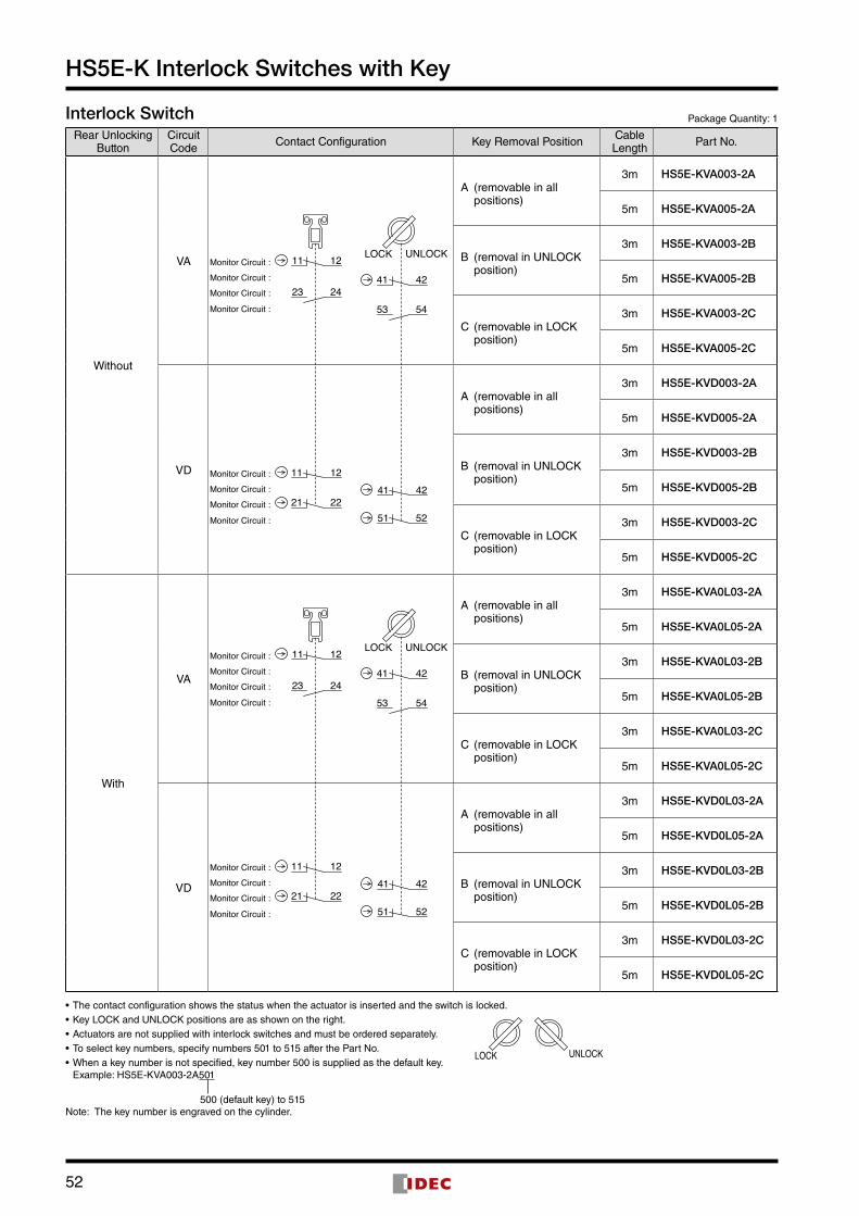
HS5E-K Interlock Switches with Key
Interlock Switch Package Quantity: 1
Rear Unlocking Button
Circuit Code Contact Configuration Key Removal Position Cable
Length Part No .
Without
VA
21 2251 52
41 421211
UNLOCKLOCK
53 54
41 42
12
23
11
24
Monitor Circuit :
Monitor Circuit :
Monitor Circuit :
Monitor Circuit :
Monitor Circuit :
Monitor Circuit :
Monitor Circuit :
Monitor Circuit :
A (removable in all positions)
3m HS5E-KVA003-2A
5m HS5E-KVA005-2A
B (removal in UNLOCK position)
3m HS5E-KVA003-2B
5m HS5E-KVA005-2B
C (removable in LOCK position)
3m HS5E-KVA003-2C
5m HS5E-KVA005-2C
VD
A (removable in all positions)
3m HS5E-KVD003-2A
5m HS5E-KVD005-2A
B (removal in UNLOCK position)
3m HS5E-KVD003-2B
5m HS5E-KVD005-2B
C (removable in LOCK position)
3m HS5E-KVD003-2C
5m HS5E-KVD005-2C
With
VA
21 2251 52
41 421211
UNLOCKLOCK
53 54
41 42
12
23
11
24
Monitor Circuit :
Monitor Circuit :
Monitor Circuit :
Monitor Circuit :
Monitor Circuit :
Monitor Circuit :
Monitor Circuit :
Monitor Circuit :
A (removable in all positions)
3m HS5E-KVA0L03-2A
5m HS5E-KVA0L05-2A
B (removal in UNLOCK position)
3m HS5E-KVA0L03-2B
5m HS5E-KVA0L05-2B
C (removable in LOCK position)
3m HS5E-KVA0L03-2C
5m HS5E-KVA0L05-2C
VD
A (removable in all positions)
3m HS5E-KVD0L03-2A
5m HS5E-KVD0L05-2A
B (removal in UNLOCK position)
3m HS5E-KVD0L03-2B
5m HS5E-KVD0L05-2B
C (removable in LOCK position)
3m HS5E-KVD0L03-2C
5m HS5E-KVD0L05-2C
• The contact configuration shows the status when the actuator is inserted and the switch is locked .• Key LOCK and UNLOCK positions are as shown on the right .• Actuators are not supplied with interlock switches and must be ordered separately .• To select key numbers, specify numbers 501 to 515 after the Part No .• When a key number is not specified, key number 500 is supplied as the default key .
Example: HS5E-KVA003-2A501
Note: The key number is engraved on the cylinder .
UNLOCKLOCK
500 (default key) to 515
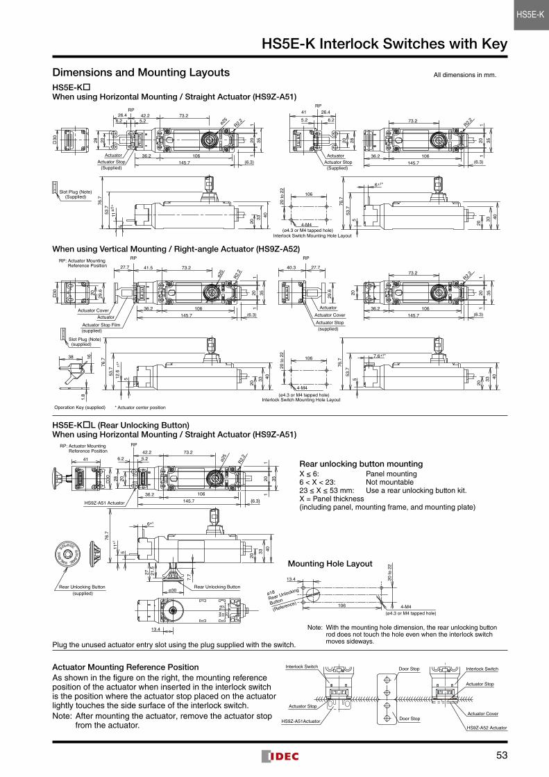
53
HS5E-K Interlock Switches with Key
Dimensions and Mounting LayoutsHS5E-K When using Horizontal Mounting / Straight Actuator (HS9Z-A51)
RP
Actuator Stop(Supplied)
Actuator
Interlock Switch Mounting Hole Layout
4-M4 (ø4.3 or M4 tapped hole)
R2.273.2
76.7
53.7
20 28
41
36.2 106145.7 (6.3)
6±1*
11
3520
5.2 6.226.4
5 40
20
33
106
20 to
22Slot Plug (Note)
(Supplied)
RP
Actuator Stop(Supplied)
Actuator
ø25R2.2
33
511
±1*
30
5.26.226.4
20
2028
40
42.2
36.2 106145.7 (6.3)
20 351
1
76.7
53.7
73.2
When using Vertical Mounting / Right-angle Actuator (HS9Z-A52)RP RP
Actuator Stop Film(supplied)
Actuator Stop(supplied)
Actuator CoverActuator Actuator Cover
Actuator
(ø4.3 or M4 tapped hole)Interlock Switch Mounting Hole Layout
4-M4
Operation Key (supplied)
Slot Plug (Note) (supplied)
RP: Actuator Mounting Reference Position
20 29.6
29.6 20
R2.2R2.2 73.2
73.2
76.7
53.7
53.7
161.
8
38
36.2 106145.7 (6.3)
41.5
12.6
±1*
(6.3)145.710636.2
7.6 ±1*
40.3
20 351
1
20 351
1
27.7 27.7
76.7
55 33
20
40 33
20
40
30
106
20 to
22
ø25
* Actuator center position
HS5E-KL (Rear Unlocking Button) When using Horizontal Mounting / Straight Actuator (HS9Z-A51)
Plug the unused actuator entry slot using the plug supplied with the switch .
Actuator Mounting Reference PositionAs shown in the figure on the right, the mounting reference position of the actuator when inserted in the interlock switch is the position where the actuator stop placed on the actuator lightly touches the side surface of the interlock switch .Note: After mounting the actuator, remove the actuator stop
from the actuator .
All dimensions in mm .
Rear unlocking button mountingX ≤ 6: Panel mounting6 < X < 23: Not mountable23 ≤ X ≤ 53 mm: Use a rear unlocking button kit .X = Panel thickness (including panel, mounting frame, and mounting plate)
Mounting Hole Layout
Note: With the mounting hole dimension, the rear unlocking button rod does not touch the hole even when the interlock switch moves sideways .
RPRP: Actuator Mounting Reference Position
HS9Z-A51 Actuator
Rear Unlocking ButtonRear Unlocking Button (supplied)
4-M4(ø4.3 or M4 tapped hole)
ø18Rear Unlocking
Button
(Reference)
R2.2
ø30
13.4
27
7.721
.5
73.2
335
42.2
6±1
36.2
2028
106145.7 (6.3)
20 351
1
20
40
76.7
11±1
41 6.2 5.2
30
2022M4
106 106
20 to
22
13.4
ø25
HS9Z-A52 Actuator
Actuator Cover
Door Stop
Door StopHS9Z-A51Actuator
Actuator Stop
Interlock Switch
Actuator Stop
Interlock Switch
HS5E-K
54
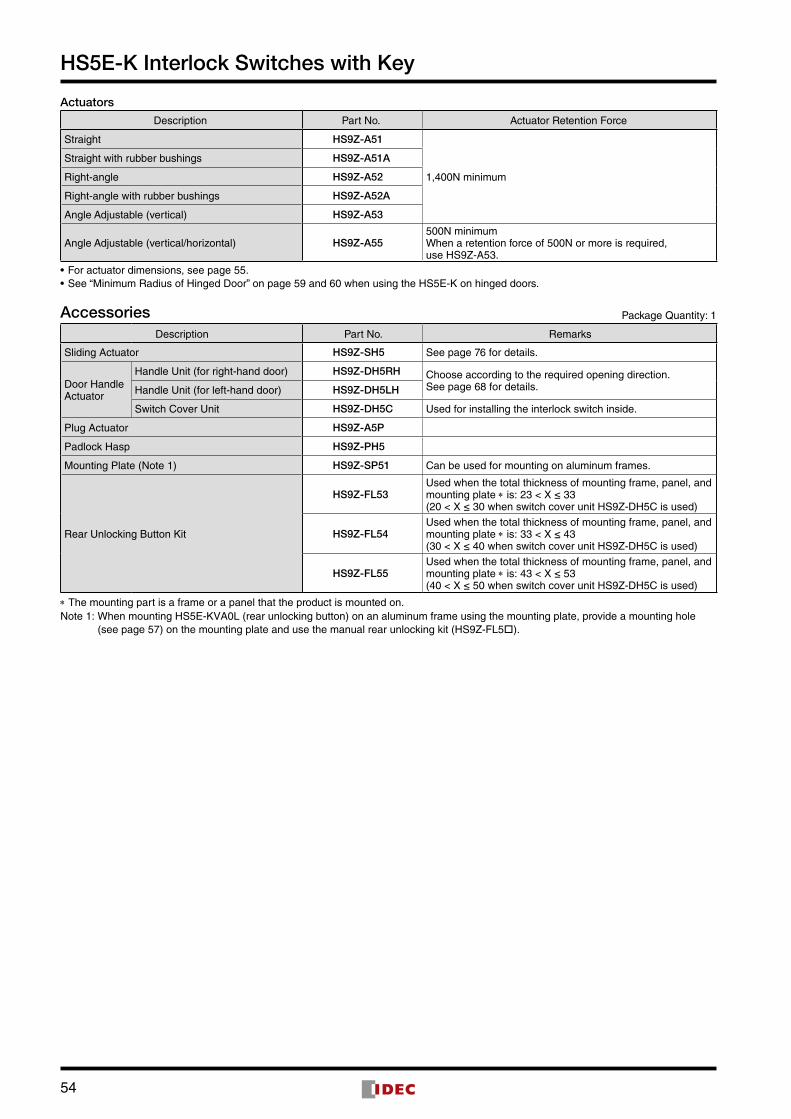
HS5E-K Interlock Switches with Key
Actuators
Description Part No . Actuator Retention Force
Straight HS9Z-A51
1,400N minimum
Straight with rubber bushings HS9Z-A51A
Right-angle HS9Z-A52
Right-angle with rubber bushings HS9Z-A52A
Angle Adjustable (vertical) HS9Z-A53
Angle Adjustable (vertical/horizontal) HS9Z-A55500N minimum When a retention force of 500N or more is required, use HS9Z-A53 .
• For actuator dimensions, see page 55 .• See “Minimum Radius of Hinged Door” on page 59 and 60 when using the HS5E-K on hinged doors .
Accessories Package Quantity: 1
Description Part No . Remarks
Sliding Actuator HS9Z-SH5 See page 76 for details .
Door Handle Actuator
Handle Unit (for right-hand door) HS9Z-DH5RH Choose according to the required opening direction .See page 68 for details .Handle Unit (for left-hand door) HS9Z-DH5LH
Switch Cover Unit HS9Z-DH5C Used for installing the interlock switch inside .
Plug Actuator HS9Z-A5P
Padlock Hasp HS9Z-PH5
Mounting Plate (Note 1) HS9Z-SP51 Can be used for mounting on aluminum frames .
Rear Unlocking Button Kit
HS9Z-FL53Used when the total thickness of mounting frame, panel, and mounting plate * is: 23 < X ≤ 33(20 < X ≤ 30 when switch cover unit HS9Z-DH5C is used)
HS9Z-FL54Used when the total thickness of mounting frame, panel, and mounting plate * is: 33 < X ≤ 43(30 < X ≤ 40 when switch cover unit HS9Z-DH5C is used)
HS9Z-FL55Used when the total thickness of mounting frame, panel, and mounting plate * is: 43 < X ≤ 53(40 < X ≤ 50 when switch cover unit HS9Z-DH5C is used)
* The mounting part is a frame or a panel that the product is mounted on .Note 1: When mounting HS5E-KVA0L (rear unlocking button) on an aluminum frame using the mounting plate, provide a mounting hole
(see page 57) on the mounting plate and use the manual rear unlocking kit (HS9Z-FL5) .
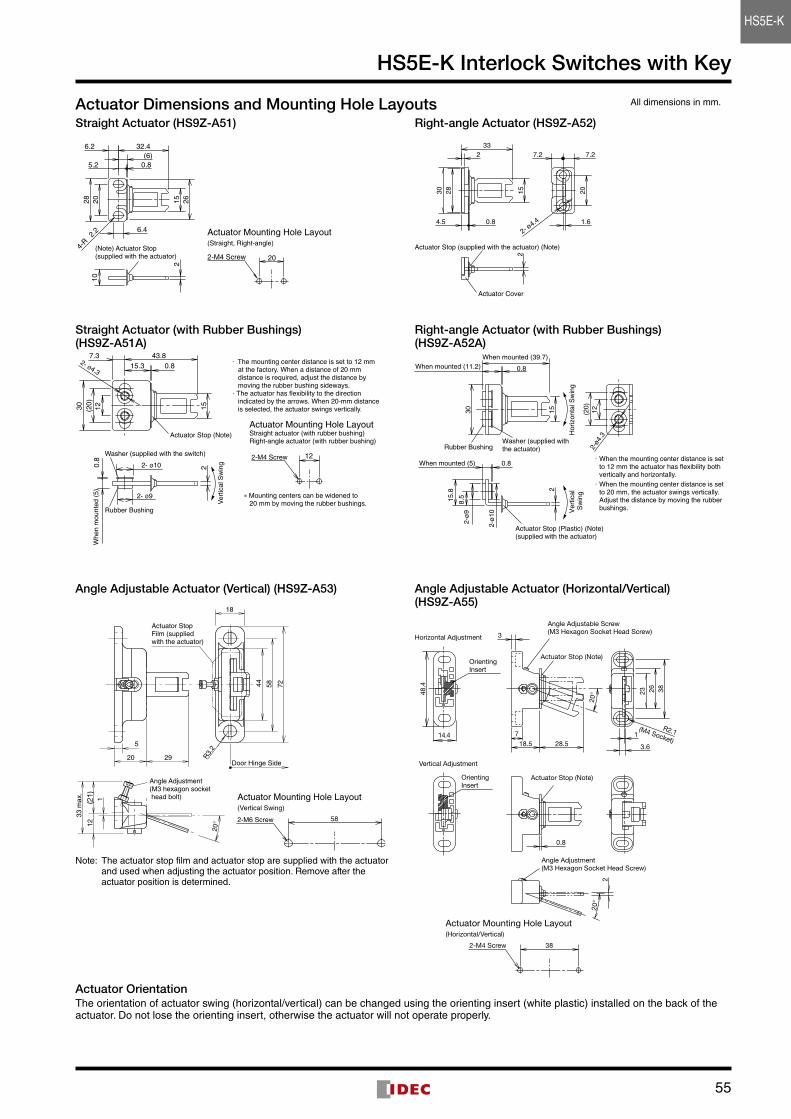
55
HS5E-K Interlock Switches with Key
Actuator Dimensions and Mounting Hole LayoutsStraight Actuator (HS9Z-A51)
(Note) Actuator Stop(supplied with the actuator)
2615
32.4
28 20
2.2
4-R
10
0.85.2(6)
6.2
6.4
2
2-M4 Screw
Actuator Mounting Hole Layout (Straight, Right-angle)
20
Right-angle Actuator (HS9Z-A52)
15
Actuator Stop (supplied with the actuator) (Note)
Actuator Cover
2
2- ø4.4
20
33
30 28
0.84.5
2 7.27.2
1.6
All dimensions in mm .
Straight Actuator (with Rubber Bushings) (HS9Z-A51A)
30
7.3 43.815.3
15
2- ø4.3
2
120.
8(2
0)
0.8
2- ø10
2- ø9
Whe
n m
ount
ed (5
)
Verti
cal S
win
g
Washer (supplied with the switch)
Rubber Bushing
Actuator Stop (Note)
· The mounting center distance is set to 12 mm at the factory. When a distance of 20 mm distance is required, adjust the distance by moving the rubber bushing sideways.
· The actuator has flexibility to the direction indicated by the arrows. When 20-mm distance is selected, the actuator swings vertically.
Right-angle Actuator (with Rubber Bushings) (HS9Z-A52A)
30 15
15.8
8.5
0.8
2
0.8
When mounted (11.2)When mounted (39.7)
When mounted (5)2-
ø9
2-ø
10
Ver
tical
S
win
gH
oriz
onta
l Sw
ing
2-ø4
.312(2
0)
Actuator Stop (Plastic) (Note)(supplied with the actuator)
Rubber BushingWasher (supplied with the actuator)
· When the mounting center distance is set to 12 mm the actuator has flexibility both vertically and horizontally.
· When the mounting center distance is set to 20 mm, the actuator swings vertically. Adjust the distance by moving the rubber bushings.
Note: The actuator stop film and actuator stop are supplied with the actuator and used when adjusting the actuator position . Remove after the actuator position is determined .
Angle Adjustable Actuator (Vertical) (HS9Z-A53)
Actuator Stop Film (supplied with the actuator)
Door Hinge Side20
5
R3.
2
725844
33 m
ax.
12(2
1) 1
20°
29
Angle Adjustment(M3 hexagon socket head bolt)
582-M6 Screw
Actuator Mounting Hole Layout (Vertical Swing)
18
Angle Adjustable Actuator (Horizontal/Vertical) (HS9Z-A55)
Actuator Stop (Note)
Angle Adjustment(M3 Hexagon Socket Head Screw)
Actuator Stop (Note)
Angle Adjustable Screw(M3 Hexagon Socket Head Screw)
(M4 Socket)7
18.5 28.5
3
3.6
1R2.1
23 26 38
38
0.8
2
20°
20°
2-M4 Screw
Actuator Mounting Hole Layout (Horizontal/Vertical)
Vertical Adjustment
Horizontal Adjustment
OrientingInsert
48.4
14.4
OrientingInsert
Actuator OrientationThe orientation of actuator swing (horizontal/vertical) can be changed using the orienting insert (white plastic) installed on the back of the actuator . Do not lose the orienting insert, otherwise the actuator will not operate properly .
122-M4 Screw
Actuator Mounting Hole LayoutStraight actuator (with rubber bushing)Right-angle actuator (with rubber bushing)
∗ Mounting centers can be widened to 20 mm by moving the rubber bushings.
HS5E-K
56
HS5E-K Interlock Switches with Key
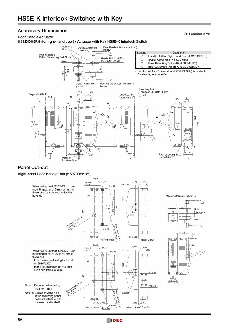
Accessory DimensionsDoor Handle ActuatorHS9Z-DH5RH (for right-hand door) / Actuator with Key HS5E-K Interlock Switch
11077°
49.5
271
256
88
47.5
220
220
204
102
5273
49
4649.8
77°
610
7 to 9
13
77
11
34 7
1283610
35
116.
517
7
Locked: 81Unlocked: 84
Mounting Part Thickness (X): 20 to 50 mm
3LOCK UNLOCK
LOCK UNLOCK
4
2 1
Material:Stainless Steel
Rear Unlocking Button(Nylon 66) (red)
Polyacetal (black)
PA
DLO
CK
49.8 35
Handle Link Shaft 8(free-cutting Steel)
Rear UnlockingButton Connecting Rod (SUS)
StainlessSteel
ø10.4
Front Handle (diecast aluminum)(black)
Rear Handle (diecast aluminum)(yellow)
Diecast Aluminum(plated)
Diecast Aluminum(plated)
56.7
79.7
UNLOCK
211.
4
Panel Cut-outRight-hand Door Handle Unit (HS9Z-DH5RH)
Rear U
nlocking Hole
ø26 to 30 (Note 2)
Rear U
nlocking Hole
ø26 to 30 (Note 2)
(34 to 41)
11 to 18
26
(102
)
(47.5)(26)
47.5
35
102
204
256
(7 to 9)13 to 206 to 16
36 to 46
8 to 20
7 to 9
Rear Unlocking Button
Hole ø22 to 30
(Note 1)
Rear Unlocking Button
Hole ø22 to 30
(Note 1)
7 to 9
8 to 20
36 to 466 to 16 13 to 20
Door Gap Door Gap
Door Gap Door Gap
(7 to 9)
256
204
102
49.5
35
47.5(26)
(47.5)
7 to 9 mm
(102
)
26
4040 4040
49.5
UNLOCKLOCK
4(6)-M5
4(6)-M5
2-M5
6-M5
Reference
Reference
3 mm
2 mm
4 mm
Mounting Position Tolerance
0.8 mm
<Front View> <Rear View>
<Front View> <Rear View>
When using the HS5E-KL on the mounting panel of 3 mm or less in thickness (use the rear unlocking button).
When using the HS5E-KL on the mounting panel of 20 to 50 mm in thickness.· Use the rear unlocking button kit
(HS9Z-FL5)· In the figure shown on the right, 40 mm frame is used.
PAD
LOC
K
All dimensions in mm .
Legend Description➀ Handle Unit for Right-hand Door (HS9Z-DH5RH)➁ Switch Cover Unit (HS9Z-DH5C)➂ Rear Unlocking Button Kit (HS9Z-FL5)➃ Interlock switch (HS5E-K) (sold separately)
• Handle unit for left-hand door (HS9Z-DH5LH) is available . For details, see page 68 .
Note 1: Required when using the HS5E-KL .
Note 2: Ensure that the hole in the mounting panel does not interfere with the rear handle shaft .
57
HS5E-K Interlock Switches with Key
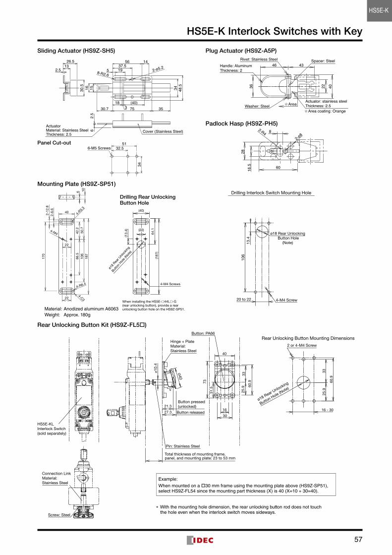
Sliding Actuator (HS9Z-SH5)
HS5E形とご使用の際は、高さ調整用のプレートにも 穴加工を行い、最低4か所(上図のA部、B部)を取付ねじで 固定してください。
5132.5
34
6-M5 Screws
4536.2
34
20~
22
HS5B形とご使用の際は、最低2か所(上図のA部)を 取付ねじで固定してください。
HS5B形安全スイッチ
A部54
36.2
34
106
20~
22
HS5E形安全スイッチ
高さ調整用プレート(お客様にてご用意願います)推奨厚み:5 mm
B部A部
145637.5195
34 48.5
(40)187530.7
1516
3
8-R2.6
1326.5
2.5
30.5
2.5
6
35
2-ø5.2
ActuatorMaterial: Stainless SteelThickness: 2.5
Cover (Stainless Steel)
0-1
50 -1
Panel Cut-out HS5E形とご使用の際は、高さ調整用のプレートにも 穴加工を行い、最低4か所(上図のA部、B部)を取付ねじで 固定してください。
5132.5
34
6-M5 Screws
4536.2
34
20~
22
HS5B形とご使用の際は、最低2か所(上図のA部)を 取付ねじで固定してください。
HS5B形安全スイッチ
A部54
36.2
34
106
20~
22
HS5E形安全スイッチ
高さ調整用プレート(お客様にてご用意願います)推奨厚み:5 mm
B部A部
145637.5195
34 48.5
(40)187530.7
1516
3
8-R2.6
1326.5
2.5
30.5
2.5
6
35
2-ø5.2
ActuatorMaterial: Stainless SteelThickness: 2.5
Cover (Stainless Steel)
0-1
50 -1
Plug Actuator (HS9Z-A5P)
36 4022
46 43
Washer: Steel
Rivet: Stainless Steel Spacer: SteelHandle: AluminumThickness: 2
Actuator: stainless steelThickness: 2.5
Area coating: Orange
Area
Padlock Hasp (HS9Z-PH5)
60
2816
.5
2-R4 8
2-ø8
Mounting Plate (HS9Z-SP51)
4-M4 Screw
106
20 to 22
13.4
ø18 Rear Unlocking Button Hole
(Note)
Drilling Interlock Switch Mounting Hole
Rear Unlocking Button Kit (HS9Z-FL5)
25.9
40
31
.5
30
16
33
60.973
Button: PA66
HS5E-KL Interlock Switch(sold separately)
ø10.
4
Ø40
Hinge + PlateMaterial:Stainless Steel
Button released
Button pressed(unlocked)
27.3
21.3
Pin: Stainless Steel
Total thickness of mounting frame, panel, and mounting plate: 23 to 53 mm
ø18 Rear Unlocking
Button Hole (N
ote)
16 - 30
3325
.9
60.9
Rear Unlocking Button Mounting Dimensions
2 or 4-M4 Screw
Screw: Steel
Connection LinkMaterial:Stainless Steel
Example:When mounted on a 30 mm frame using the mounting plate above (HS9Z-SP51), select HS9Z-FL54 since the mounting part thickness (X) is 40 (X=10 + 30=40) .
* With the mounting hole dimension, the rear unlocking button rod does not touch the hole even when the interlock switch moves sideways .
ø18
Rear U
nlock
ing
Butto
n Hol
e (N
ote)
4-M4 Screws
When installing the HS5E-44L-G(rear unlocking button), provide a rearunlocking button hole on the HS9Z-SP51.
4-R6.4
2-12
.82-
6.6
4-R3.
3
4-M4
6 10
40
170
22
106
187
50.7
42.2
224-C3
86.5
(40)
(22)
64.1
(13.
4)
(187
)
Drilling Rear Unlocking Button Hole
Material: Anodized aluminum A6063Weight: Approx . 180g
HS5E-K
58
HS5E-K Interlock Switches with Key
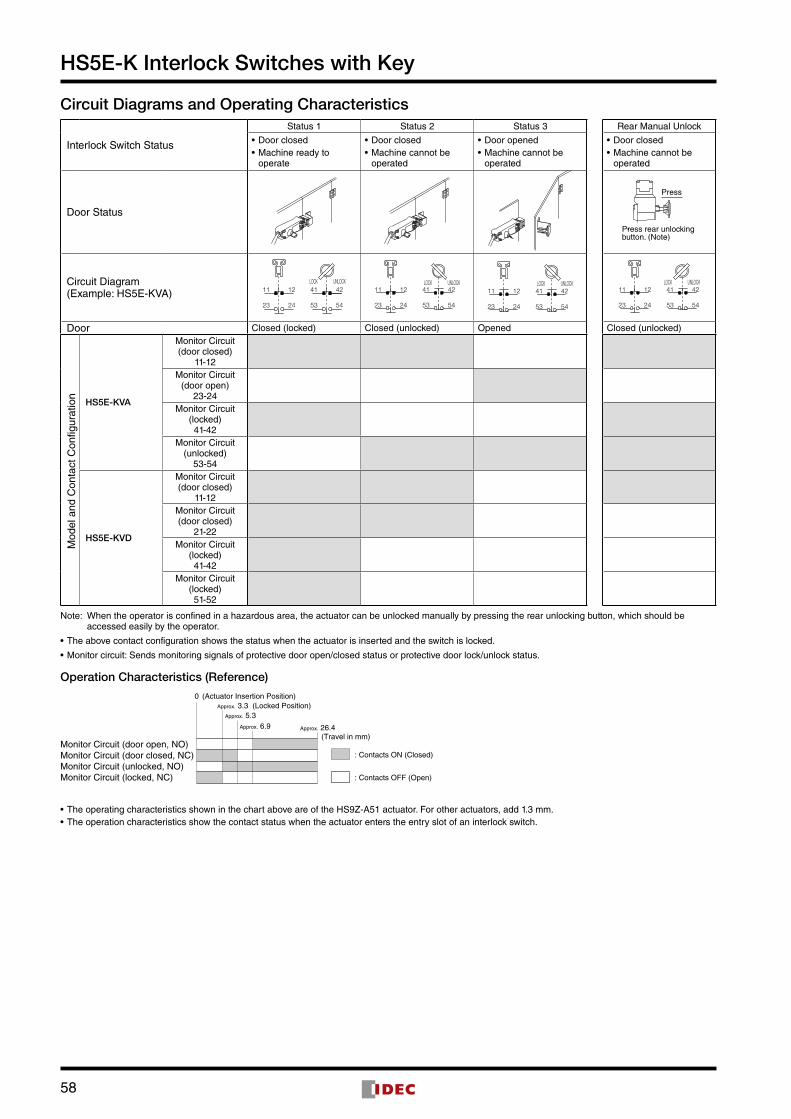
Circuit Diagrams and Operating Characteristics
Interlock Switch Status
Status 1 Status 2 Status 3 Rear Manual Unlock
• Door closed• Machine ready to
operate
• Door closed• Machine cannot be
operated
• Door opened• Machine cannot be
operated
• Door closed• Machine cannot be
operated
Door Status
Press rear unlocking button. (Note)
Press
Circuit Diagram (Example: HS5E-KVA) 11
23
42
54
12
24
41
53
LOCK UNLOCK
53
41
24
12
54
42
23
11LOCK UNLOCK
11
23
42
54
12
24
41
53
LOCK UNLOCK11
23
42
54
12
24
41
53
LOCK UNLOCK
Door Closed (locked) Closed (unlocked) Opened Closed (unlocked)
Mod
el a
nd C
onta
ct C
onfig
urat
ion
HS5E-KVA
Monitor Circuit(door closed)
11-12Monitor Circuit
(door open)23-24
Monitor Circuit(locked)41-42
Monitor Circuit(unlocked)
53-54
HS5E-KVD
Monitor Circuit(door closed)
11-12Monitor Circuit(door closed)
21-22Monitor Circuit
(locked)41-42
Monitor Circuit(locked)51-52
Note: When the operator is confined in a hazardous area, the actuator can be unlocked manually by pressing the rear unlocking button, which should be accessed easily by the operator .
• The above contact configuration shows the status when the actuator is inserted and the switch is locked .
• Monitor circuit: Sends monitoring signals of protective door open/closed status or protective door lock/unlock status .
Operation Characteristics (Reference)
• The operating characteristics shown in the chart above are of the HS9Z-A51 actuator . For other actuators, add 1 .3 mm .• The operation characteristics show the contact status when the actuator enters the entry slot of an interlock switch .
Approx. 26.4
Approx. 5.3 Approx. 6.9
Approx. 3.3 (Locked Position)0
(Travel in mm)
(Actuator Insertion Position)
: Contacts OFF (Open)
: Contacts ON (Closed)Monitor Circuit (door open, NO)Monitor Circuit (door closed, NC)Monitor Circuit (unlocked, NO)Monitor Circuit (locked, NC)
59
HS5E-K Interlock Switches with Key
Safety Precautions • In order to avoid electric shock or fire, turn the power off before installation, removal, wire connection, maintenance, or inspection of the interlock switch . • If relays are used in the circuit between the interlock switch and the load, consider the danger and use safety relays, since welding or sticking contacts of standard relays may invalidate the functions of the interlock switch . Perform a risk assessment and establish a safety circuit that satisfies the requirement of the safety category .
• Do not place a PLC in the circuit between the interlock switch and the load . Safety and security can be endan-gered in the event of a malfunction of the PLC . • Do not disassemble or modify the interlock switch, other-wise a breakdown or an accident may occur . • Do not install the actuator in a location where the human body may come in contact . Otherwise injury may occur .
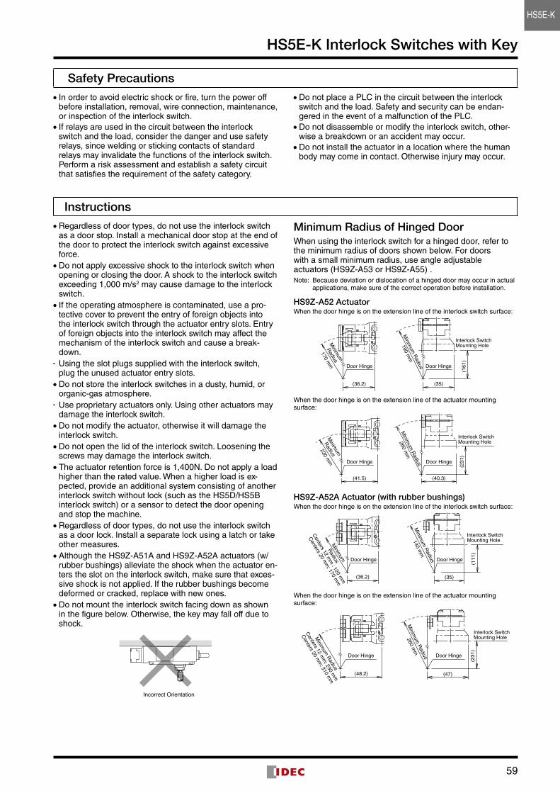
Instructions • Regardless of door types, do not use the interlock switch as a door stop . Install a mechanical door stop at the end of the door to protect the interlock switch against excessive force . • Do not apply excessive shock to the interlock switch when opening or closing the door . A shock to the interlock switch exceeding 1,000 m/s2 may cause damage to the interlock switch . • If the operating atmosphere is contaminated, use a pro-tective cover to prevent the entry of foreign objects into the interlock switch through the actuator entry slots . Entry of foreign objects into the interlock switch may affect the mechanism of the interlock switch and cause a break-down .
• Using the slot plugs supplied with the interlock switch, plug the unused actuator entry slots . • Do not store the interlock switches in a dusty, humid, or organic-gas atmosphere .
• Use proprietary actuators only . Using other actuators may damage the interlock switch . • Do not modify the actuator, otherwise it will damage the interlock switch . • Do not open the lid of the interlock switch . Loosening the screws may damage the interlock switch . • The actuator retention force is 1,400N . Do not apply a load higher than the rated value . When a higher load is ex-pected, provide an additional system consisting of another interlock switch without lock (such as the HS5D/HS5B interlock switch) or a sensor to detect the door opening and stop the machine . • Regardless of door types, do not use the interlock switch as a door lock . Install a separate lock using a latch or take other measures . • Although the HS9Z-A51A and HS9Z-A52A actuators (w/rubber bushings) alleviate the shock when the actuator en-ters the slot on the interlock switch, make sure that exces-sive shock is not applied . If the rubber bushings become deformed or cracked, replace with new ones . • Do not mount the interlock switch facing down as shown in the figure below . Otherwise, the key may fall off due to shock .
Incorrect Orientation
Minimum Radius of Hinged DoorWhen using the interlock switch for a hinged door, refer to the minimum radius of doors shown below . For doors with a small minimum radius, use angle adjustable actuators (HS9Z-A53 or HS9Z-A55) .Note: Because deviation or dislocation of a hinged door may occur in actual
applications, make sure of the correct operation before installation .
HS9Z-A52 ActuatorWhen the door hinge is on the extension line of the interlock switch surface:
Door Hinge Door Hinge
(161
)
(35)
Interlock Switch Mounting Hole
(36.2)
190 mm
170 mm
Minim
um R
adius
Minim
um
Radius
When the door hinge is on the extension line of the actuator mounting surface:
(231
)
(41.5) (40.3)
230 mm
260 mm
Door Hinge Door Hinge
Interlock Switch Mounting Hole
Minim
um R
adius
Minim
um
Radius
HS9Z-A52A Actuator (with rubber bushings)When the door hinge is on the extension line of the interlock switch surface:
(35)(36.2)
(111
)
Minim
um
Radius
Centers 12 m
m : 120 m
m
Centers 20 m
m: 170 m
m
Minim
um R
adius
140 mm
Door Hinge Door Hinge
Interlock Switch Mounting Hole
When the door hinge is on the extension line of the actuator mounting surface:
(47)(48.2)
(231
)
260 mm
Door Hinge Door Hinge
Interlock Switch Mounting Hole
Minim
um R
adius
Minim
um R
adius
Centers 12 m
m: 230 m
m
Centers 20 m
m: 310 m
m
HS5E-K
60
HS5E-K Interlock Switches with Key
Instructions
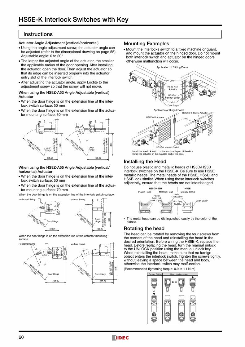
Actuator Angle Adjustment (vertical/horizontal) • Using the angle adjustment screw, the actuator angle can be adjusted (refer to the dimensional drawing on page 55) . Adjustable angle: 0 to 20° • The larger the adjusted angle of the actuator, the smaller the applicable radius of the door opening . After installing the actuator, open the door . Then adjust the actuator so that its edge can be inserted properly into the actuator entry slot of the interlock switch . • After adjusting the actuator angle, apply Loctite to the adjustment screw so that the screw will not move .
When using the HS9Z-A53 Angle Adjustable (vertical) Actuator • When the door hinge is on the extension line of the inter-lock switch surface: 50 mm • When the door hinge is on the extension line of the actua-tor mounting surface: 80 mm
(36.2)
(38)
Inte
rlock
Sw
itch
Mou
ntin
g H
ole
Inte
rlock
Sw
itch
Mou
ntin
g H
ole
Door Hinge
Door Hinge
Minimum Radius
Minimum Radius
50 mm80 mm
(68)
(56.5)
When using the HS9Z-A55 Angle Adjustable (vertical/horizontal) Actuator • When the door hinge is on the extension line of the inter-lock switch surface: 50 mm • When the door hinge is on the extension line of the actua-tor mounting surface: 70 mm
When the door hinge is on the extension line of the interlock switch surface:
When the door hinge is on the extension line of the actuator mounting surface
Mounting Examples • Mount the interlocks switch to a fixed machine or guard, and mount the actuator on the hinged door . Do not mount both interlock switch and actuator on the hinged doors, otherwise malfunction will occur .
ActuatorHS9Z-A51
Door
Interlock SwitchHS5E-K
Door Stop
Application of Sliding Doors
Latch
Application of Hinged Doors
HS5E-K Interlock Switch
Install the interlock switch on the immovable part of the door.Install the actuator on the movable part of the door.
HS9Z-A52 Actuator
HS9Z-SH5 Sliding Actuator
Door
Installing the HeadDo not use plastic and metallic heads of HS5D/HS5B interlock switches on the HS5E-K . Be sure to use HS5E metallic heads . The metal heads of the HS5E, HS5D, and HS5B look similar . When using these interlock switches adjacently, ensure that the heads are not interchanged .
Color: Black
PlasticColor: red,
black or gray
HS5EHS5D/HS5B
Metallic HeadMetallic HeadPlastic HeadMetal
Color: Silver
Color: Grayor red
* The metal head can be distinguished easily by the color of the plastic .
Rotating the headThe head can be rotated by removing the four screws from the corners of the head and reinstalling the head in the desired orientation . Before wiring the HS5E-K, replace the head . Before replacing the head, turn the manual unlock to the UNLOCK position using the manual unlock key . When reinstalling the head, make sure that no foreign object enters the interlock switch . Tighten the screws tightly, without leaving a space between the head and body, otherwise the interlock switch may malfunction .(Recommended tightening torque: 0 .9 to 1 .1 N·m)
Head can be rotatedFactory Setting
LOCK UNLOCK LOCK UNLOCK LOCK UNLOCK LOCK UNLOCK
(58)
(38)
Inte
rlock
Sw
itch
Mou
ntin
g H
ole
Inte
rlock
Sw
itch
Mou
ntin
g H
ole
(55.5)
(36.2)
(55.5)
(36.2)
70 mm
Minimum Radius
50 mm
Minimum Radius
Minimum Radius
50 mm
Minimum Radius
70 mm
Horizontal Swing Vertical Swing
Horizontal Swing Vertical Swing
Door Hinge Door Hinge
Door HingeDoor
Hinge
61
HS5E-K Interlock Switches with Key
Instructions
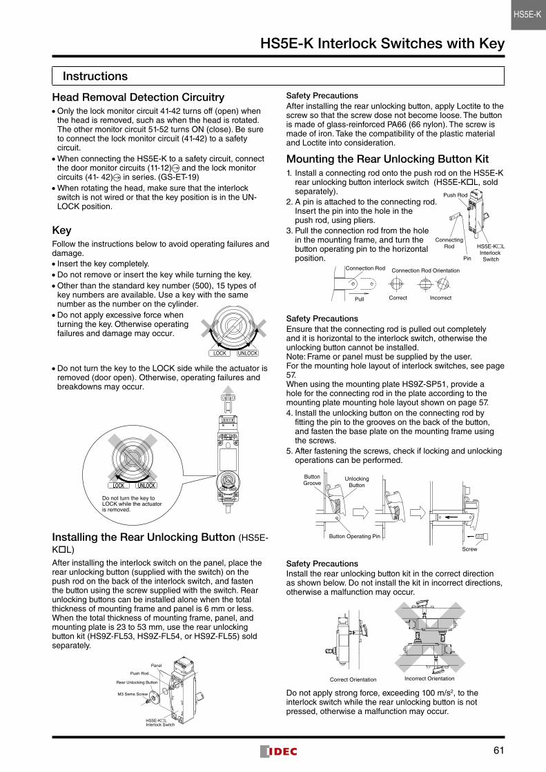
Head Removal Detection Circuitry • Only the lock monitor circuit 41-42 turns off (open) when the head is removed, such as when the head is rotated . The other monitor circuit 51-52 turns ON (close) . Be sure to connect the lock monitor circuit (41-42) to a safety circuit . • When connecting the HS5E-K to a safety circuit, connect the door monitor circuits (11-12) and the lock monitor circuits (41- 42) in series . (GS-ET-19) • When rotating the head, make sure that the interlock switch is not wired or that the key position is in the UN-LOCK position .
KeyFollow the instructions below to avoid operating failures and damage . • Insert the key completely . • Do not remove or insert the key while turning the key . • Other than the standard key number (500), 15 types of key numbers are available . Use a key with the same number as the number on the cylinder .
LOCK UNLOCK
• Do not apply excessive force when turning the key . Otherwise operating failures and damage may occur .
• Do not turn the key to the LOCK side while the actuator is removed (door open) . Otherwise, operating failures and breakdowns may occur .
LOCK UNLOCK
Do not turn the key to LOCK while the actuator is removed.
LOCK UNLOCK
Installing the Rear Unlocking Button (HS5E-KL) After installing the interlock switch on the panel, place the rear unlocking button (supplied with the switch) on the push rod on the back of the interlock switch, and fasten the button using the screw supplied with the switch . Rear unlocking buttons can be installed alone when the total thickness of mounting frame and panel is 6 mm or less . When the total thickness of mounting frame, panel, and mounting plate is 23 to 53 mm, use the rear unlocking button kit (HS9Z-FL53, HS9Z-FL54, or HS9Z-FL55) sold separately .
Safety PrecautionsAfter installing the rear unlocking button, apply Loctite to the screw so that the screw dose not become loose . The button is made of glass-reinforced PA66 (66 nylon) . The screw is made of iron . Take the compatibility of the plastic material and Loctite into consideration .
Mounting the Rear Unlocking Button Kit1 . Install a connecting rod onto the push rod on the HS5E-K
rear unlocking button interlock switch (HS5E-KL, sold separately) .
2 . A pin is attached to the connecting rod . Insert the pin into the hole in the push rod, using pliers .
3 . Pull the connection rod from the hole in the mounting frame, and turn the button operating pin to the horizontal position .
Correct Incorrect
Connection Rod Orientation
Pull
Connection Rod
Safety PrecautionsEnsure that the connecting rod is pulled out completely and it is horizontal to the interlock switch, otherwise the unlocking button cannot be installed .Note: Frame or panel must be supplied by the user .For the mounting hole layout of interlock switches, see page 57 . When using the mounting plate HS9Z-SP51, provide a hole for the connecting rod in the plate according to the mounting plate mounting hole layout shown on page 57 . 4 . Install the unlocking button on the connecting rod by
fitting the pin to the grooves on the back of the button, and fasten the base plate on the mounting frame using the screws .
5 . After fastening the screws, check if locking and unlocking operations can be performed .
Button Operating Pin
ButtonGroove
Screw
UnlockingButton
Safety PrecautionsInstall the rear unlocking button kit in the correct direction as shown below . Do not install the kit in incorrect directions, otherwise a malfunction may occur .
Correct Orientation Incorrect Orientation
Do not apply strong force, exceeding 100 m/s2, to the interlock switch while the rear unlocking button is not pressed, otherwise a malfunction may occur .
HS5E-KLInterlock Switch
Rear Unlocking Button
M3 Sems Screw
Panel
Push Rod
ConnectingRod
Push Rod
HS5E-KLInterlock SwitchPin
HS5E-K
62
HS5E-K Interlock Switches with Key
Instructions
Manual Unlocking using the Rear Unlock-ing Button • The rear unlocking button is used by the operator confined in a hazardous area for emergency escape .
Unlock
Rear Unlocking Button
Unlock
Rear UnlockingButton Kit
How to operate • When the rear unlocking button is pressed, the interlock switch is unlocked and the door can be opened . • To lock the interlock switch, pull back the button . • When the button remains pressed, the interlock switch cannot be locked even if the door is closed, and the main circuit remains open .
Safety Precautions • Install the rear unlocking button in a place where only the operator inside the hazardous area can use it . Do not install the button in a place where an operator outside the hazardous area can use it, otherwise the interlock switch may be unlocked during usual machine operation, causing danger . • Operate the rear unlocking button by hand only . Do not operate using a tool or with excessive force . Do not apply force to the button from the direction other than the proper direction, otherwise the button will be damaged .
Recommended Tightening Torque for Mounting Screws • HS5E-K interlock switch: 1 .8 to 2 .2 N·m (four M4 screws) (Note) • Rear unlocking button: 0 .5 to 0 .7 N·m • Rear unlocking button kit: 4 .8 to 5 .2 N·m (M5 Screw) • Actuators HS9Z-A51: 1 .8 to 2 .2 N·m (two M4 screws) (Note) HS9Z-A52: 0 .8 to 1 .2 N·m (two M4 Phillips screws) HS9Z-A51A/A52A: 1 .0 to 1 .5 N·m (two M4 screws) (Note) HS9Z-A53: 4 .5 to 5 .5 N·m (two M6 screws) (Note)HS9Z-A55: 1 .0 to 1 .5 N·m (two M4 screws) (Note)
Note: The above recommended tightening torques of the mounting screws are the values confirmed with hex socket head bolts . When other screws are used and tightened to a smaller torque, make sure that the screws do not become loose after mounting .
• Mounting bolts must be provided by the users . • To avoid unauthorized or unintended removal of the in-terlock switch and the actuator, it is recommended that the interlock switch and actuator are installed in a secure manner, for example using special screws or welding the screws .
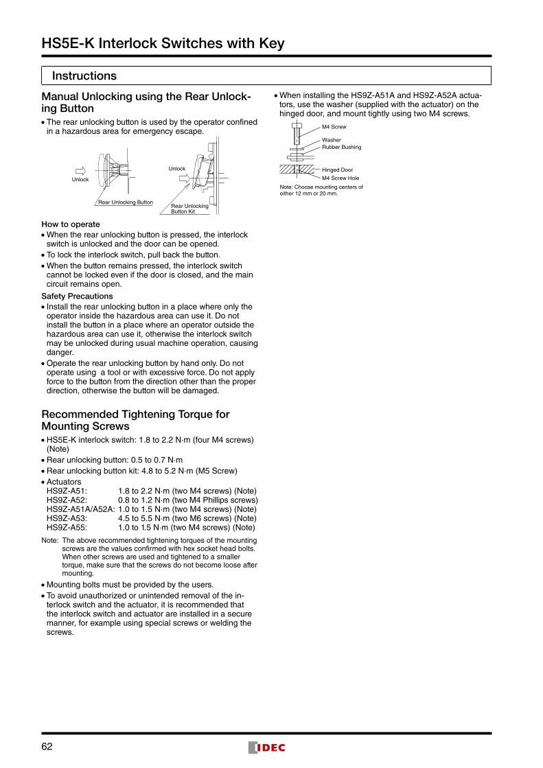
• When installing the HS9Z-A51A and HS9Z-A52A actua-tors, use the washer (supplied with the actuator) on the hinged door, and mount tightly using two M4 screws .
M4 Screw Hole
Hinged Door
Note: Choose mounting centers ofeither 12 mm or 20 mm.
M4 Screw
Rubber BushingWasher
63
HS5E-K Interlock Switches with Key
Instructions
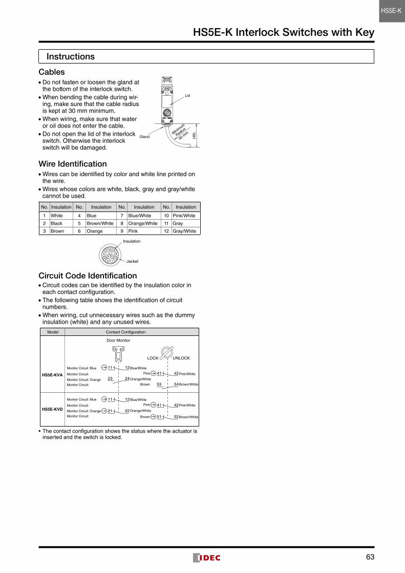
Cables • Do not fasten or loosen the gland at the bottom of the interlock switch . • When bending the cable during wir-ing, make sure that the cable radius is kept at 30 mm minimum . • When wiring, make sure that water or oil does not enter the cable . • Do not open the lid of the interlock switch . Otherwise the interlock switch will be damaged .
Wire Identification • Wires can be identified by color and white line printed on the wire . • Wires whose colors are white, black, gray and gray/white cannot be used .
No . Insulation No . Insulation No . Insulation No . Insulation
1 White 4 Blue 7 Blue/White 10 Pink/White
2 Black 5 Brown/White 8 Orange/White 11 Gray
3 Brown 6 Orange 9 Pink 12 Gray/White
Jacket
Insulation
2 110 12
9 1187
6435
Circuit Code Identification • Circuit codes can be identified by the insulation color in each contact configuration . • The following table shows the identification of circuit numbers . • When wiring, cut unnecessary wires such as the dummy insulation (white) and any unused wires .
Door Monitor
HS5E-KVA
HS5E-KVD
11 124241
5251
53 54
41 4212
23
11
24
Contact ConfigurationModel
LOCK UNLOCK
2221
Monitor Circuit: Blue
Monitor Circuit: Orange
Monitor Circuit:
Monitor Circuit:
Monitor Circuit: Blue
Monitor Circuit: Orange
Monitor Circuit:
Monitor Circuit:
Orange/White
Brown
Pink
Brown
Pink
Blue/White
Orange/White
Blue/White
Pink/White
Brown/White
Pink/White
Brown/White
• The contact configuration shows the status where the actuator is inserted and the switch is locked .
30 mm
GlandMinim
um
Radius
Lid
(48)
HS5E-K
64
HS5E-K Interlock Switches with Key
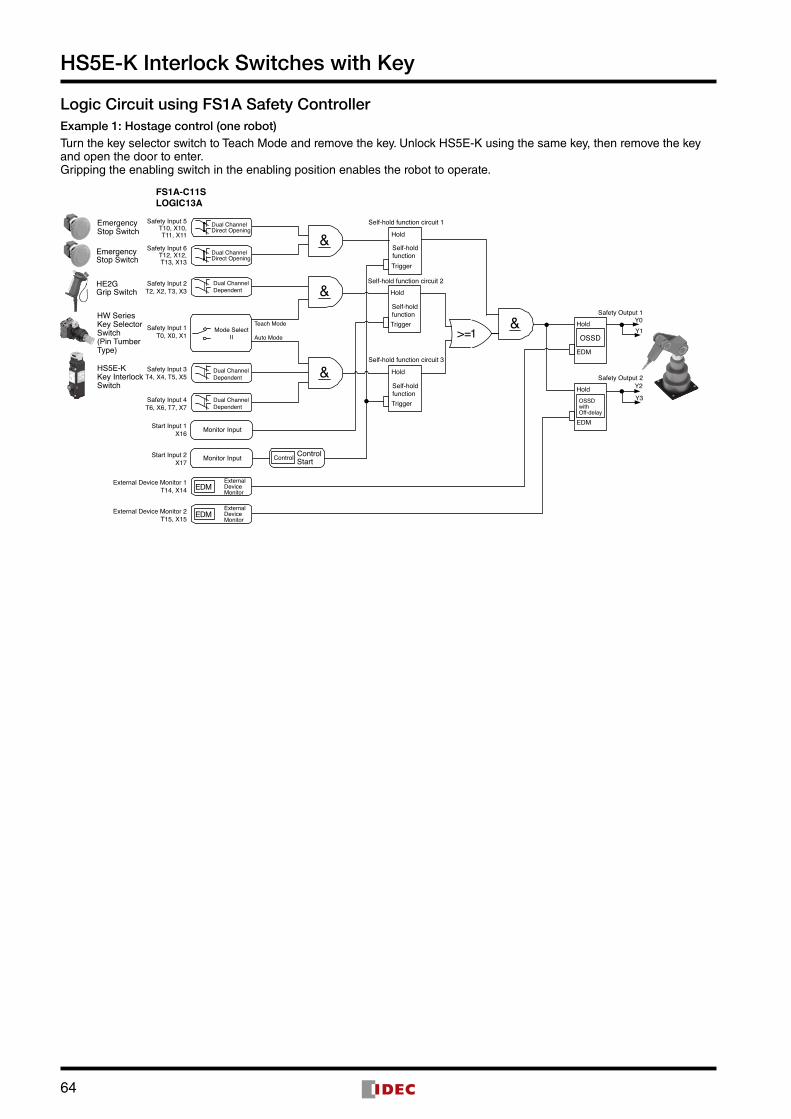
Logic Circuit using FS1A Safety ControllerExample 1: Hostage control (one robot)Turn the key selector switch to Teach Mode and remove the key . Unlock HS5E-K using the same key, then remove the key and open the door to enter .Gripping the enabling switch in the enabling position enables the robot to operate .
FS1A-C11SLOGIC13A
EmergencyStop Switch
EmergencyStop Switch
HE2GGrip Switch
HW SeriesKey SelectorSwitch(Pin TumberType)
HS5E-KKey InterlockSwitch
>=1Safety Input 1T0, X0, X1
Teach Mode
Auto Mode
Control
Safety Input 2T2, X2, T3, X3
Safety Input 6T12, X12,T13, X13
Safety Input 5T10, X10,T11, X11
Safety Input 4T6, X6, T7, X7
Safety Input 3T4, X4, T5, X5
Start Input 1X16
Start Input 2X17
External Device Monitor 1T14, X14
Monitor Input
Monitor Input
ExternalDeviceMonitor
Self-hold function circuit 1
Mode SelectII
Hold
Trigger
Self-holdfunction
Self-hold function circuit 2
Y0Y1
Y2
Y3
Safety Output 1
Safety Output 2
Hold
EDM
Hold
EDM
Self-hold function circuit 3
Hold
Trigger
Self-holdfunction
Hold
Trigger
Self-holdfunction
&
&
&
&Dual ChannelDirect Opening
Dual ChannelDirect Opening
Dual ChannelDependent
Dual ChannelDependent
Dual ChannelDependent
ControlStart
EDM
EDMExternal Device Monitor 2T15, X15
OSSDwithOff-delay
OSSD
ExternalDeviceMonitor
65
HS5E-K Interlock Switches with Key
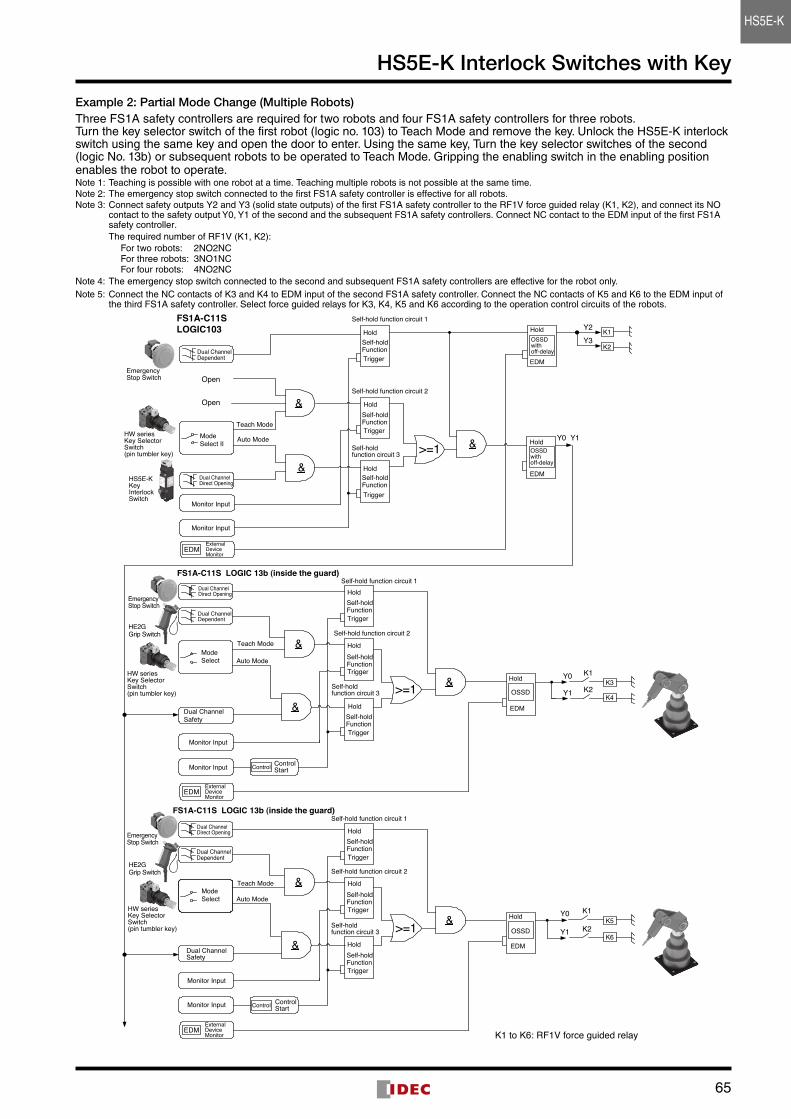
Example 2: Partial Mode Change (Multiple Robots)Three FS1A safety controllers are required for two robots and four FS1A safety controllers for three robots . Turn the key selector switch of the first robot (logic no . 103) to Teach Mode and remove the key . Unlock the HS5E-K interlock switch using the same key and open the door to enter . Using the same key, Turn the key selector switches of the second (logic No . 13b) or subsequent robots to be operated to Teach Mode . Gripping the enabling switch in the enabling position enables the robot to operate .Note 1: Teaching is possible with one robot at a time . Teaching multiple robots is not possible at the same time .Note 2: The emergency stop switch connected to the first FS1A safety controller is effective for all robots .Note 3: Connect safety outputs Y2 and Y3 (solid state outputs) of the first FS1A safety controller to the RF1V force guided relay (K1, K2), and connect its NO
contact to the safety output Y0, Y1 of the second and the subsequent FS1A safety controllers . Connect NC contact to the EDM input of the first FS1A safety controller .The required number of RF1V (K1, K2):
For two robots: 2NO2NC For three robots: 3NO1NCFor four robots: 4NO2NC
Note 4: The emergency stop switch connected to the second and subsequent FS1A safety controllers are effective for the robot only .Note 5: Connect the NC contacts of K3 and K4 to EDM input of the second FS1A safety controller . Connect the NC contacts of K5 and K6 to the EDM input of
the third FS1A safety controller . Select force guided relays for K3, K4, K5 and K6 according to the operation control circuits of the robots .
Teach Mode
Auto Mode
Y0
Y1
EDM
&
&
Self-hold function circuit 2
Self-hold function circuit 1
OSSD
OSSD
FS1A-C11S LOGIC 13b (inside the guard)
Control
&
FS1A-C11SLOGIC103
Teach Mode
Auto Mode
Y0
Y1
EDM
&
&
Self-hold function circuit 2
Self-holdfunction circuit 3
Self-hold function circuit 1FS1A-C11S LOGIC 13b (inside the guard)
Control
&
Y2
Y0 Y1
&
Self-hold function circuit 2
EDM
&
&
Self-hold function circuit 1
Self-holdfunction circuit 3
Self-holdfunction circuit 3
Open
Open
K1
K2
K3
K4
K5
K6
K1
K2
K1
K2
Dual ChannelDirect Opening
Monitor Input
Dual ChannelDependent
Dual ChannelDependent
Dual ChannelDependent
Dual ChannelDirect Opening
Dual ChannelDirect Opening
Monitor Input
Monitor Input
Monitor Input
Monitor Input
Monitor Input
Dual ChannelSafety
Dual ChannelSafety
ExternalDeviceMonitor
ExternalDeviceMonitor
ExternalDeviceMonitor
ModeSelect II
ModeSelect
ModeSelect
ControlStart
>=1
>=1
>=1
Hold
Trigger
Self-holdFunction
Self-holdFunction
Self-holdFunction
Self-holdFunction
Self-holdFunction
Self-holdFunction
Self-holdFunction
Self-holdFunction
Self-holdFunction
Hold
Trigger
Hold
Trigger
Hold
Trigger
Hold
Trigger
Hold
Trigger
Hold
Trigger
Hold
Trigger
Hold
ControlStart
Trigger
Hold
Hold
Hold
Hold
EDM
EDM
EDM
EDM
OSSDwithoff-delay
OSSDwithoff-delay
Y3
Teach Mode
Auto Mode
HE2GGrip Switch
HE2GGrip Switch
HW seriesKey SelectorSwitch(pin tumbler key)
EmergencyStop Switch
EmergencyStop Switch
EmergencyStop Switch
HW seriesKey SelectorSwitch(pin tumbler key)
HW seriesKey SelectorSwitch(pin tumbler key)
HS5E-KKeyInterlockSwitch
K1 to K6: RF1V force guided relay
HS5E-K