Embed Size (px)
Citation preview
App note
Rev. 1.1 © CopperGate Communications CONFIDENTIAL 1/18
HPNA over Coax application note
January 2005 Overview The purpose of this document is to serve as a handbook for the design and installation of HPNA 3.0 products over coax media and over mixed phone/coax media. Section 1 gives general information and discusses general guidelines which should be followed during the design of the installation. Section 2 describes the applications available over the coax media and gives specific examples and guidelines for each of the implementations listed below:
1. Networking over Coax cables typically used in Media Server and STB (Set Top Box) home networking applications.
2. MxU access over Coax cables. 3. Networking over mixed Phone wires and Coax cables typically used in
FTTP/PON systems for home networking and multimedia distribution applications.
App note
Rev. 1.1 © CopperGate Communications CONFIDENTIAL 2/18
Table of Contents 1. General guidelines ........................................................................................................................... 3 1.1. Network operation mode.............................................................................................................. 3 1.2. Rate vs. attenuation rule of thumb ............................................................................................... 3 1.3. Wall Outlets ................................................................................................................................. 4 1.4. Amplifiers .................................................................................................................................... 5 1.5. Coexistence with DOCSIS........................................................................................................... 6 1.6. Coexistence with Return Channel................................................................................................ 7 1.7. Connecting an HPNA device to the Coax network...................................................................... 7 1.7.1. Cable video signal.................................................................................................................... 7 1.7.2. Satellite signal .......................................................................................................................... 8 1.7.3. Master in MxU access topology............................................................................................... 9 2. Applications ..................................................................................................................................... 9 2.1. In-house networking over Coax cables ........................................................................................ 9 2.1.1. Topologies ............................................................................................................................. 10 2.1.2. Installation guides .................................................................................................................. 10 2.1.2.1. Placement of Master .......................................................................................................... 10 2.1.2.2. Isolator ............................................................................................................................... 10 2.1.2.3. Physical connection ........................................................................................................... 12 2.2. MxU access over Coax cables ................................................................................................... 12 2.2.1. Topologies ............................................................................................................................. 13 2.2.2. Installation guides .................................................................................................................. 13 2.2.2.1. Placement of Master .......................................................................................................... 13 2.2.2.2. BW Allocation ................................................................................................................... 13 2.2.2.3. Physical connection ........................................................................................................... 14 2.3. Networking over mixed Phone wires and Coax cables .............................................................. 14 2.3.1. Topologies ............................................................................................................................. 14 2.3.2. Installation guides .................................................................................................................. 18 2.3.2.1. Placement of Master .......................................................................................................... 18 2.3.2.2. Isolator ............................................................................................................................... 18 2.3.2.3. Physical connection point .................................................................................................. 19 2.3.3. Limitations ............................................................................................................................. 19 2.3.3.1. Connectivity (maximum attenuation) ................................................................................ 19 2.3.3.2. Back to Back (minimum attenuation) ................................................................................ 19 3. Disclaimer...................................................................................................................................... 19
App note
Rev. 1.1 © CopperGate Communications CONFIDENTIAL 3/18
1. General guidelines There are several guidelines that should be followed in the design of HPNA products over Coax in order to achieve maximum utilization and to avoid problems caused by incorrect use.
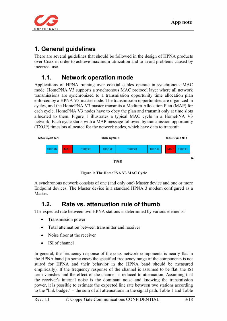
1.1. Network operation mode Applications of HPNA running over coaxial cables operate in synchronous MAC mode. HomePNA V3 supports a synchronous MAC protocol layer where all network transmissions are synchronized to a transmission opportunity time allocation plan enforced by a HPNA V3 master node. The transmission opportunities are organized in cycles, and the HomePNA V3 master transmits a Medium Allocation Plan (MAP) for each cycle. HomePNA V3 nodes have to obey the plan and transmit only at time slots allocated to them. Figure 1 illustrates a typical MAC cycle in a HomePNA V3 network. Each cycle starts with a MAP message followed by transmission opportunity (TXOP) timeslots allocated for the network nodes, which have data to transmit.
TIME
MAC Cycle N
MAP TXOP #3TXOP #2TXOP #1 TXOP #4 MAP TXOP #1TXOP #N
MAC Cycle N-1 MAC Cycle N+1
Figure 1: The HomePNA V3 MAC Cycle
A synchronous network consists of one (and only one) Master device and one or more Endpoint devices. The Master device is a standard HPNA 3 modem configured as a Master.
1.2. Rate vs. attenuation rule of thumb The expected rate between two HPNA stations is determined by various elements:
• Transmission power
• Total attenuation between transmitter and receiver
• Noise floor at the receiver
• ISI of channel In general, the frequency response of the coax network components is nearly flat in the HPNA band (in some cases the specified frequency range of the components is not suited for HPNA and their behavior in the HPNA band should be measured empirically). If the frequency response of the channel is assumed to be flat, the ISI term vanishes and the effect of the channel is reduced to attenuation. Assuming that the receiver's internal noise is the dominant noise and knowing the transmission power, it is possible to estimate the expected line rate between two stations according to the "link budget" – the sum of all attenuations in the signal path. Table 1 and Table
App note
Rev. 1.1 © CopperGate Communications CONFIDENTIAL 4/19
2 list the measured line rate for varying attenuation values for Coax only and for mixed Coax/phone applications respectively.
Coax only application ("Coax2") Path attenuation [dB] Line Rate [Mb/s] 0-41 128 42-45 112 46-48 96 49-52 80 53-55 64 56-57 48 58-60 32 61 0 – no connectivity
Table 1: Rate vs. Attenuation for Coax2
Mixed Coax/phone application ("Coax1") Path attenuation [dB] Line Rate [Mb/s] 0-39 128 40-44 112 45-46 96 47-50 80 51-53 64 54-56 48 57-61 32 62 0 – no connectivity
Table 2: Rate vs. Attenuation for Coax1 In practice there could be variations in rate due to imperfect terminations which might cause reflections.
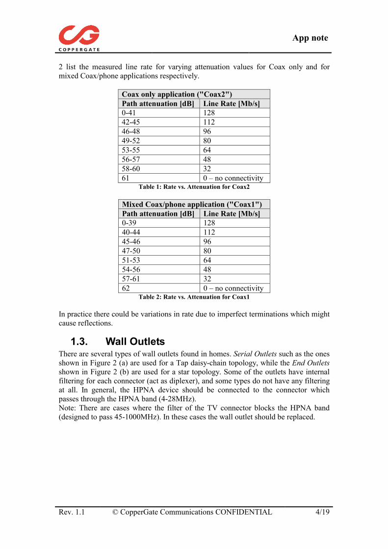
1.3. Wall Outlets There are several types of wall outlets found in homes. Serial Outlets such as the ones shown in Figure 2 (a) are used for a Tap daisy-chain topology, while the End Outlets shown in Figure 2 (b) are used for a star topology. Some of the outlets have internal filtering for each connector (act as diplexer), and some types do not have any filtering at all. In general, the HPNA device should be connected to the connector which passes through the HPNA band (4-28MHz). Note: There are cases where the filter of the TV connector blocks the HPNA band (designed to pass 45-1000MHz). In these cases the wall outlet should be replaced.
App note
Rev. 1.1 © CopperGate Communications CONFIDENTIAL 5/19
Figure 2: Typical wall outlets - (a) Serial (Tap) outlets. (b) End (Through) outlets.
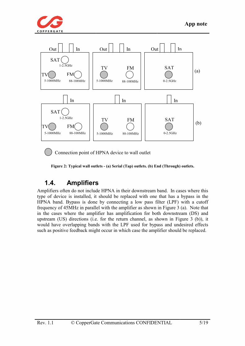
1.4. Amplifiers Amplifiers often do not include HPNA in their downstream band. In cases where this type of device is installed, it should be replaced with one that has a bypass in the HPNA band. Bypass is done by connecting a low pass filter (LPF) with a cutoff frequency of 45MHz in parallel with the amplifier as shown in Figure 3 (a). Note that in the cases where the amplifier has amplification for both downstream (DS) and upstream (US) directions (i.e. for the return channel, as shown in Figure 3 (b)), it would have overlapping bands with the LPF used for bypass and undesired effects such as positive feedback might occur in which case the amplifier should be replaced.
In
SATFMTVFMTV
SAT
Out InOut InOut
In In In
(a)
(b)
5-1000MHz
1-2.5GHz
88-108MHz 88-108MHz 0-2.5GHz
SAT FM TV FM
SAT1-2.5GHz
TV 88-108MHz 88-108MHz 0-2.5GHz
5-1000MHz
5-1000MHz 5-1000MHz
Connection point of HPNA device to wall outlet
App note
Rev. 1.1 © CopperGate Communications CONFIDENTIAL 6/19
Figure 3: (a) Bypass of amplifier. (b) Bidirectional amplifier.
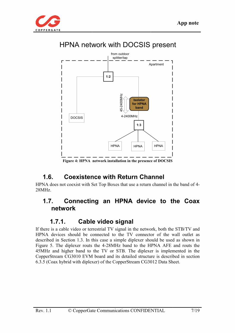
1.5. Coexistence with DOCSIS HPNA does not coexist with DOCSIS on the same physical media and a separate coax line should be used for the DOCSIS modem with an appropriate filter at the combining point with the HPNA coax network as seen in Figure 4.
(a)
Downstream 45 – 2000MHz
LPF 0-45MHz
(b)
Downstream 45 – 2000MHz
Upstream 5-40MHz
App note
Rev. 1.1 © CopperGate Communications CONFIDENTIAL 7/19
HPNA network with DOCSIS present
1:3
Apartment
4-2400MHz45
-240
0MH
z
from outdoorsplitter/tap
Isolatorfor HPNA
band
HPNA
1:2
HPNAHPNA
DOCSIS
Figure 4: HPNA network installation in the presence of DOCSIS
1.6. Coexistence with Return Channel HPNA does not coexist with Set Top Boxes that use a return channel in the band of 4-28MHz.
1.7. Connecting an HPNA device to the Coax network
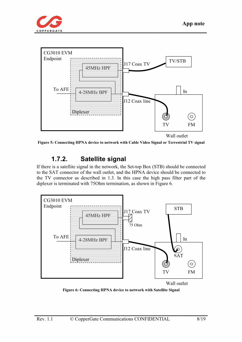
1.7.1. Cable video signal If there is a cable video or terrestrial TV signal in the network, both the STB/TV and HPNA devices should be connected to the TV connector of the wall outlet as described in Section 1.3. In this case a simple diplexer should be used as shown in Figure 5. The diplexer routs the 4-28MHz band to the HPNA AFE and routs the 45MHz and higher band to the TV or STB. The diplexer is implemented in the CopperStream CG3010 EVM board and its detailed structure is described in section 6.3.5 (Coax hybrid with diplexer) of the CopperStream CG3012 Data Sheet.
App note
Rev. 1.1 © CopperGate Communications CONFIDENTIAL 8/19
Figure 5: Connecting HPNA device to network with Cable Video Signal or Terrestrial TV signal
1.7.2. Satellite signal If there is a satellite signal in the network, the Set-top Box (STB) should be connected to the SAT connector of the wall outlet, and the HPNA device should be connected to the TV connector as described in 1.3. In this case the high pass filter part of the diplexer is terminated with 75Ohm termination, as shown in Figure 6.
Figure 6: Connecting HPNA device to network with Satellite Signal
To AFE
CG3010 EVM Endpoint
4-28MHz BPF
45MHz HPF
J12 Coax line
J17 Coax TV
Diplexer
STB
FM TV
In
Wall outlet
SAT
75 Ohm
To AFE
CG3010 EVM Endpoint
4-28MHz BPF
45MHz HPF
J12 Coax line
J17 Coax TV
Diplexer
TV/STB
FM TV
In
Wall outlet
App note
Rev. 1.1 © CopperGate Communications CONFIDENTIAL 9/19
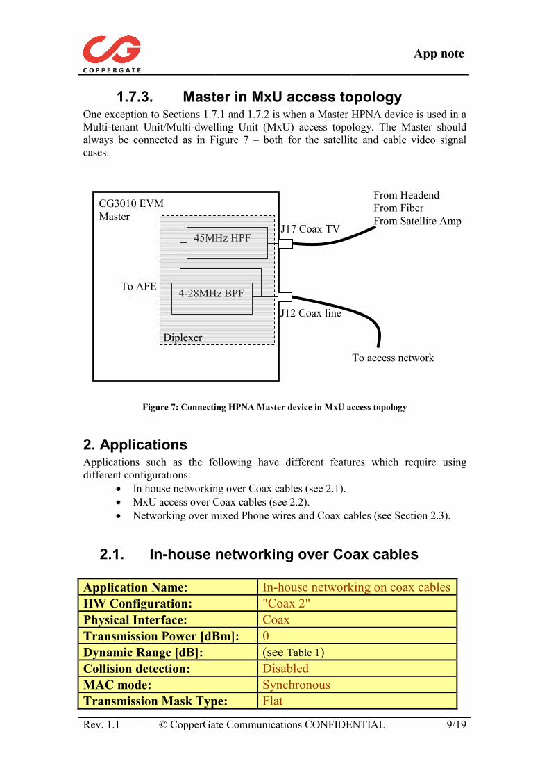
1.7.3. Master in MxU access topology One exception to Sections 1.7.1 and 1.7.2 is when a Master HPNA device is used in a Multi-tenant Unit/Multi-dwelling Unit (MxU) access topology. The Master should always be connected as in Figure 7 – both for the satellite and cable video signal cases.
Figure 7: Connecting HPNA Master device in MxU access topology
2. Applications Applications such as the following have different features which require using different configurations:
• In house networking over Coax cables (see 2.1). • MxU access over Coax cables (see 2.2). • Networking over mixed Phone wires and Coax cables (see Section 2.3).
2.1. In-house networking over Coax cables Application Name: In-house networking on coax cablesHW Configuration: "Coax 2" Physical Interface: Coax Transmission Power [dBm]: 0 Dynamic Range [dB]: (see Table 1) Collision detection: Disabled MAC mode: Synchronous Transmission Mask Type: Flat
To AFE
CG3010 EVM Master
4-28MHz BPF
45MHz HPF
J12 Coax line
J17 Coax TV
Diplexer
To access network
From Headend From Fiber From Satellite Amp
App note
Rev. 1.1 © CopperGate Communications CONFIDENTIAL 10/19
Table 3: Specifications of networking over coax application
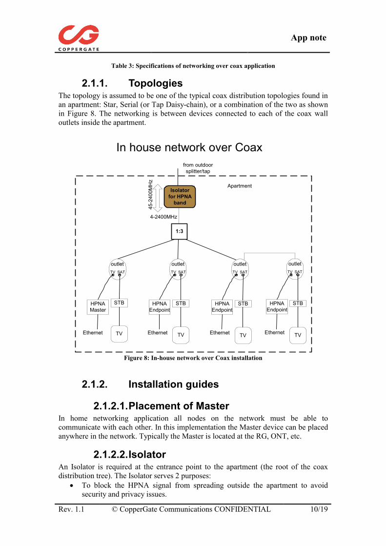
2.1.1. Topologies The topology is assumed to be one of the typical coax distribution topologies found in an apartment: Star, Serial (or Tap Daisy-chain), or a combination of the two as shown in Figure 8. The networking is between devices connected to each of the coax wall outlets inside the apartment.
In house network over Coax
1:3
STBSTB
Apartment
4-2400MHz
45-2
400M
Hz
from outdoorsplitter/tap
outlet outlet outletTV SAT TV SAT TV SAT
Isolatorfor HPNA
band
TV TV
STB
TV
HPNAMaster
HPNAEndpoint
HPNAEndpoint
Ethernet Ethernet Ethernet
outletTV SAT
STB
TV
HPNAEndpoint
Ethernet
Figure 8: In-house network over Coax installation
2.1.2. Installation guides
2.1.2.1. Placement of Master In home networking application all nodes on the network must be able to communicate with each other. In this implementation the Master device can be placed anywhere in the network. Typically the Master is located at the RG, ONT, etc.
2.1.2.2. Isolator An Isolator is required at the entrance point to the apartment (the root of the coax distribution tree). The Isolator serves 2 purposes:
• To block the HPNA signal from spreading outside the apartment to avoid security and privacy issues.
App note
Rev. 1.1 © CopperGate Communications CONFIDENTIAL 11/19
• To reduce the isolation between splitter outputs and thus increase the connectivity coverage between stations connected to the network. The isolator introduces mismatched impedance at the splitter's input which causes the isolation between outputs to be reduced by about 10dB or more. The mismatching is done only in the HPNA band and is effective only for the splitter topology.
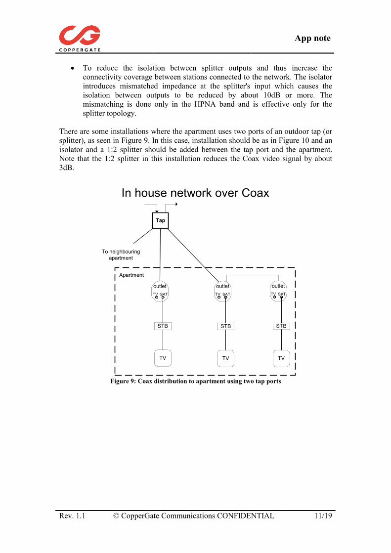
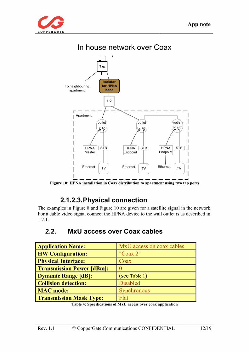
There are some installations where the apartment uses two ports of an outdoor tap (or splitter), as seen in Figure 9. In this case, installation should be as in Figure 10 and an isolator and a 1:2 splitter should be added between the tap port and the apartment. Note that the 1:2 splitter in this installation reduces the Coax video signal by about 3dB.
In house network over Coax
Tap
STB
Apartment
outlet outletTV SAT TV SAT
TV
STB
TV
outletTV SAT
STB
TV
To neighbouringapartment
Figure 9: Coax distribution to apartment using two tap ports
App note
Rev. 1.1 © CopperGate Communications CONFIDENTIAL 12/19
In house network over Coax
STB
Apartment
outlet outletTV SAT TV SAT
Isolatorfor HPNA
band
TV
STB
TV
HPNAMaster
HPNAEndpoint
Ethernet Ethernet
outletTV SAT
STB
TV
HPNAEndpoint
Ethernet
To neighbouringapartment
1:2
Tap
Figure 10: HPNA installation in Coax distribution to apartment using two tap ports
2.1.2.3. Physical connection The examples in Figure 8 and Figure 10 are given for a satellite signal in the network. For a cable video signal connect the HPNA device to the wall outlet is as described in 1.7.1.
2.2. MxU access over Coax cables Application Name: MxU access on coax cables HW Configuration: "Coax 2" Physical Interface: Coax Transmission Power [dBm]: 0 Dynamic Range [dB]: (see Table 1) Collision detection: Disabled MAC mode: Synchronous Transmission Mask Type: Flat
Table 4: Specifications of MxU access over coax application
App note
Rev. 1.1 © CopperGate Communications CONFIDENTIAL 13/19
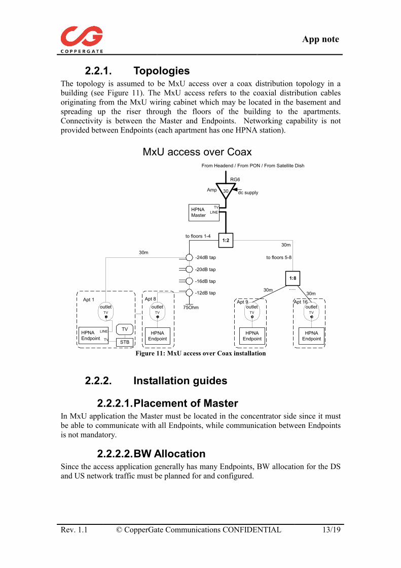
2.2.1. Topologies The topology is assumed to be MxU access over a coax distribution topology in a building (see Figure 11). The MxU access refers to the coaxial distribution cables originating from the MxU wiring cabinet which may be located in the basement and spreading up the riser through the floors of the building to the apartments. Connectivity is between the Master and Endpoints. Networking capability is not provided between Endpoints (each apartment has one HPNA station).
MxU access over Coax
30
1:2
1:8
dc supply
From Headend / From PON / From Satellite Dish
Amp
30m
RG6
.....
75Ohm
-24dB tap
to floors 1-4
to floors 5-8
HPNAEndpoint
HPNAMaster
outletTV
HPNAEndpoint
outletTV
30m30m
HPNAEndpoint
outletTV
HPNAEndpoint
outletTV ....
Apt 1 Apt 8 Apt 9 Apt 16
30m
-20dB tap
-16dB tap
-12dB tap
TVLINE
LINE TV
TV STB
Figure 11: MxU access over Coax installation
2.2.2. Installation guides
2.2.2.1. Placement of Master In MxU application the Master must be located in the concentrator side since it must be able to communicate with all Endpoints, while communication between Endpoints is not mandatory.
2.2.2.2. BW Allocation Since the access application generally has many Endpoints, BW allocation for the DS and US network traffic must be planned for and configured.
App note
Rev. 1.1 © CopperGate Communications CONFIDENTIAL 14/19
2.2.2.3. Physical connection The example shown in Figure 11 includes a cable video signal in the network. For a satellite signal, connect the HPNA device to the wall outlet is as described in Section 1.7.2. The Master should be connected as described in Section 1.7.3.
2.3. Networking over mixed Phone wires and Coax cables
Application Name: Mixed Phone/Coax Network HW Configuration: "Coax 1" "Phone 1" Physical Interface: Coax Phone Transmission Power [dBm]: 0 -7 Dynamic Range [dB]: (see Table 2) Collision detection: Disabled Enabled MAC mode: Synchronous Synchronous Transmission Mask Type: Notched Notched
Table 5: Specifications of Mixed Phone/Coax network application
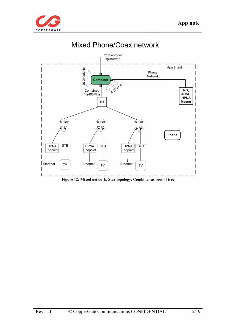
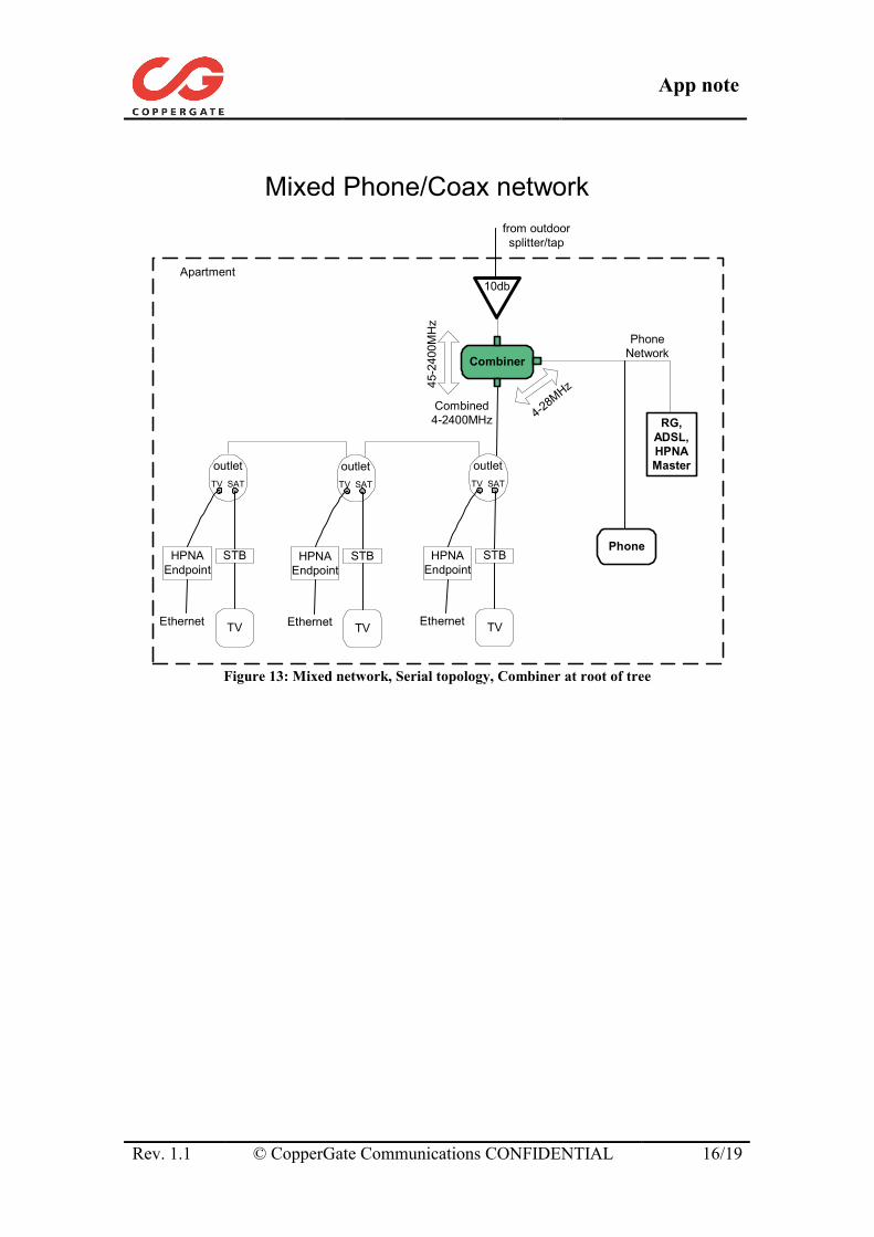
2.3.1. Topologies The topology is assumed to be typical coax and phone distribution topologies inside an apartment. A combined phone/coax network is created by using a passive Combiner device. The networking is between stations connected to the coax or phoneline wall outlets inside the apartment. There are two possible ways to combine the phone and coax networks:
1. Combiner is installed at root of the coax distribution tree (at the entrance point). For example see Figure 12 and Figure 13.
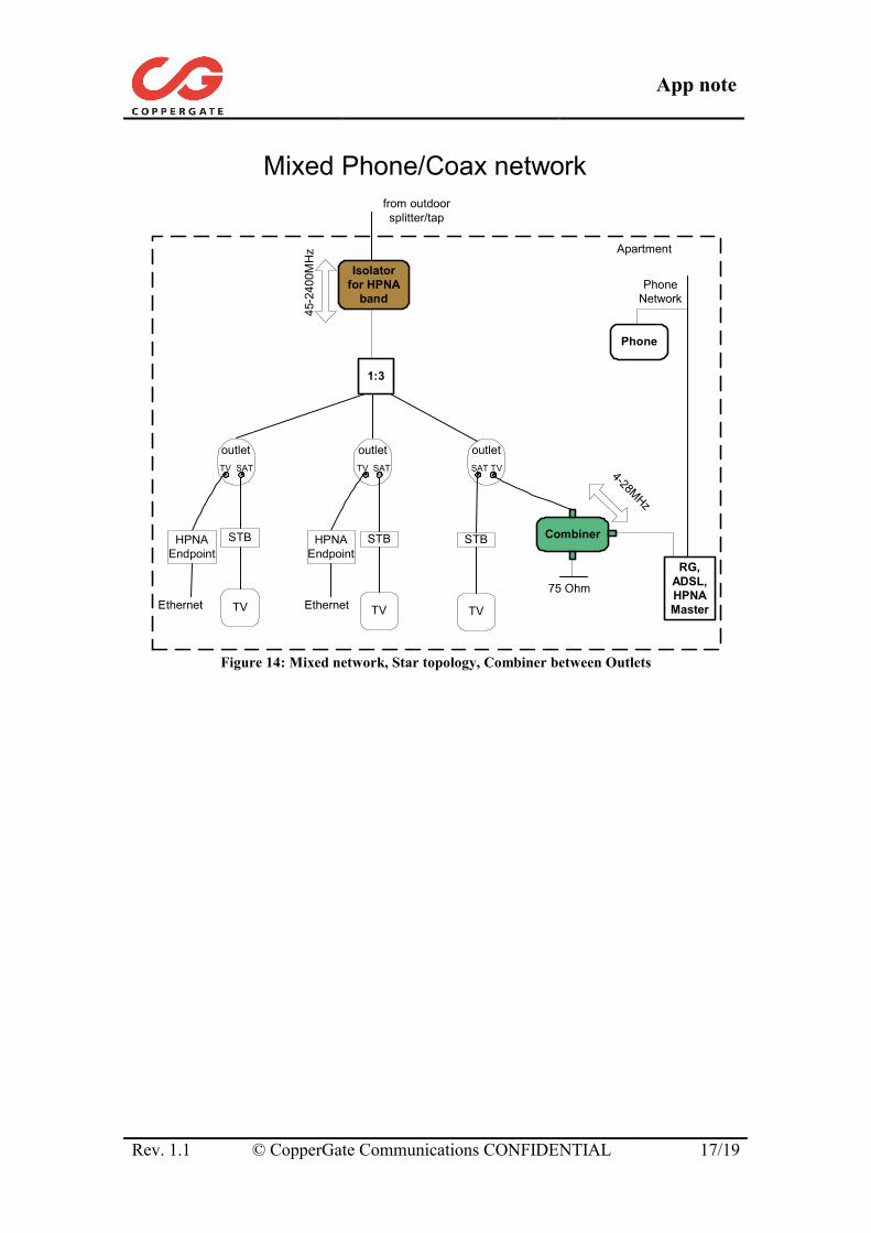
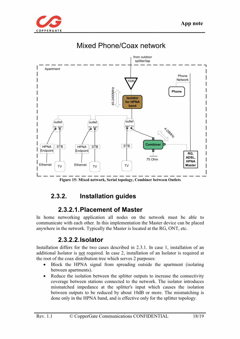
2. Combiner is installed in one of the rooms connecting a phone outlet to a coax outlet. For example see Figure 14 and Figure 15
App note
Rev. 1.1 © CopperGate Communications CONFIDENTIAL 15/19
Mixed Phone/Coax network
ApartmentPhone
Network
Combined4-2400MHz
RG,ADSL,HPNAMaster
Phone
Combiner
4-28MHz45
-240
0MH
z
from outdoorsplitter/tap
1:3
STBSTB
outlet outlet outletTV SAT TV SAT TV SAT
TV TV
STB
TV
HPNAEndpoint
HPNAEndpoint
HPNAEndpoint
Ethernet Ethernet Ethernet
Figure 12: Mixed network, Star topology, Combiner at root of tree
App note
Rev. 1.1 © CopperGate Communications CONFIDENTIAL 16/19
Mixed Phone/Coax network
Apartment10db
from outdoorsplitter/tap
Combiner
PhoneNetwork
RG,ADSL,HPNAMaster
Phone
outletTV SAT
STB
TV
HPNAEndpoint
Ethernet
outletTV SAT
STB
TV
HPNAEndpoint
Ethernet
outletTV SAT
STB
TV
HPNAEndpoint
Ethernet
Combined4-2400MHz 4-2
8MHz45
-240
0MH
z
Figure 13: Mixed network, Serial topology, Combiner at root of tree
App note
Rev. 1.1 © CopperGate Communications CONFIDENTIAL 17/19
Mixed Phone/Coax network
Apartment
PhoneNetwork
RG,ADSL,HPNAMaster
Phone
Combiner
4-28MHz
45-2
400M
Hz
from outdoorsplitter/tap
1:3
STBSTB
outlet outlet outletTV SAT TV SAT SAT TV
TV TV
STB
TV
HPNAEndpoint
HPNAEndpoint
Ethernet Ethernet
Isolatorfor HPNA
band
75 Ohm
Figure 14: Mixed network, Star topology, Combiner between Outlets
App note
Rev. 1.1 © CopperGate Communications CONFIDENTIAL 18/19
Mixed Phone/Coax network
Apartment
10db
from outdoorsplitter/tap
outletTV SAT
STB
TV
HPNAEndpoint
Ethernet
outletTV SAT
STB
TV
HPNAEndpoint
Ethernet
PhoneNetwork
RG,ADSL,HPNAMaster
Phone
Combiner
4-28MHz
outletSAT TV
STB
TV
75 Ohm
Isolatorfor HPNA
band45-2
400M
Hz
Figure 15: Mixed network, Serial topology, Combiner between Outlets
2.3.2. Installation guides
2.3.2.1. Placement of Master In home networking application all nodes on the network must be able to communicate with each other. In this implementation the Master device can be placed anywhere in the network. Typically the Master is located at the RG, ONT, etc.
2.3.2.2. Isolator Installation differs for the two cases described in 2.3.1. In case 1, installation of an additional Isolator is not required. In case 2, installation of an Isolator is required at the root of the coax distribution tree which serves 2 purposes:
• Block the HPNA signal from spreading outside the apartment (isolating between apartments).
• Reduce the isolation between the splitter outputs to increase the connectivity coverage between stations connected to the network. The isolator introduces mismatched impedance at the splitter's input which causes the isolation between outputs to be reduced by about 10dB or more. The mismatching is done only in the HPNA band, and is effective only for the splitter topology.
App note
Rev. 1.1 © CopperGate Communications CONFIDENTIAL 19/19
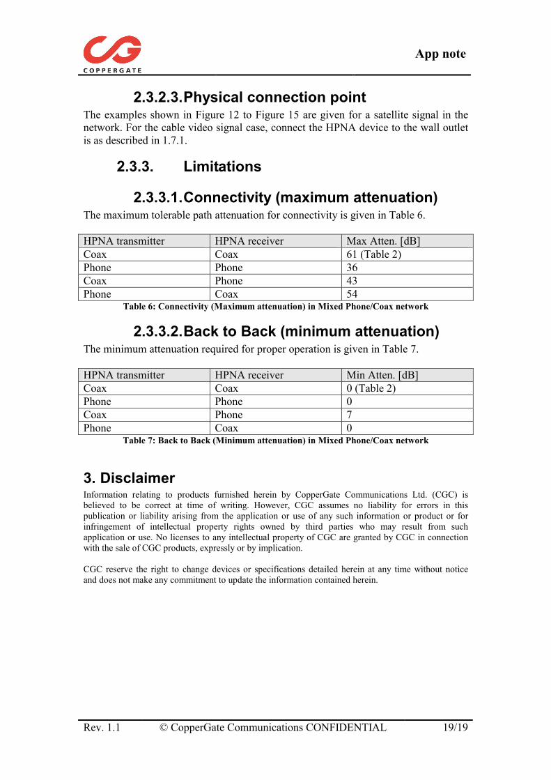
2.3.2.3. Physical connection point The examples shown in Figure 12 to Figure 15 are given for a satellite signal in the network. For the cable video signal case, connect the HPNA device to the wall outlet is as described in 1.7.1.
2.3.3. Limitations
2.3.3.1. Connectivity (maximum attenuation) The maximum tolerable path attenuation for connectivity is given in Table 6. HPNA transmitter HPNA receiver Max Atten. [dB] Coax Coax 61 (Table 2) Phone Phone 36 Coax Phone 43 Phone Coax 54
Table 6: Connectivity (Maximum attenuation) in Mixed Phone/Coax network
2.3.3.2. Back to Back (minimum attenuation) The minimum attenuation required for proper operation is given in Table 7. HPNA transmitter HPNA receiver Min Atten. [dB] Coax Coax 0 (Table 2) Phone Phone 0 Coax Phone 7 Phone Coax 0
Table 7: Back to Back (Minimum attenuation) in Mixed Phone/Coax network
3. Disclaimer Information relating to products furnished herein by CopperGate Communications Ltd. (CGC) is believed to be correct at time of writing. However, CGC assumes no liability for errors in this publication or liability arising from the application or use of any such information or product or for infringement of intellectual property rights owned by third parties who may result from such application or use. No licenses to any intellectual property of CGC are granted by CGC in connection with the sale of CGC products, expressly or by implication. CGC reserve the right to change devices or specifications detailed herein at any time without notice and does not make any commitment to update the information contained herein.