Embed Size (px)
Citation preview
HPLC Troubleshooting Guide
®
II 1
®
Gilson HPLC Components
Troubleshooting – Getting StartedGeneral Guidelines Checklist
Isolating & Identifying ProblemsSoftware HardwareSystemTrainingComputerLaboratory/Facility
Understanding CarryoverHow Solvent Selection Affects CarryoverHow Optimizing Rinse & Injection Procedures Reduce CarryoverHow Probe Selection Affects CarryoverHow Plumbing Affects Carryover
Probe & Transfer Tubing Selection
Troubleshooting Carryover
Troubleshooting Hardware Components PumpsValvesDetectorsAutomatic Liquid Handling/InjectorsFraction Collectors
Putting it All Together
AppendixAppendix A: PEEK Tubing Pressure vs. Flow RateAppendix B: Column Sizes and CapacititesAppendix C: Tubing: Internal Diameters & VolumesAppendix D: Pressure Conversion ChartAppendix E: Solvent Polarity Chart
Table of Contents
1
334
557
10212222
2323232529
31
33
353536373940
43
4445464748
Using This Guide
This guide was organized to provide both a systematic approach and a component approach to assist you with identifying and solving common HPLC problems. The techniques included in this guide are specific to Gilson HPLC systems, allowing you to better understand and optimize your Gilson system in the laboratory.
Purpose:• Assists you with quick identification of common problems• Provides a list of potential solutions to problems
Benefits:• Helps you learn more about your Gilson system• Outlines systematic troubleshooting approaches• References quick techniques and tips in a convenient booklet
As you work with your Gilson HPLC system, use this guide as a reference tool. This guide is intended to be comprehensive with respect to many different Gilson HPLC system configurations; however, if you are unable to find the specific answer to your question, Gilson’s Customer Service Department is available for assistance.
Gilson Customer Service [email protected]
There is an extensive education and training program available from our Gilson Knowledge Center. Our program offers complimentary Instrument TechTips and web seminars, along with additional options for personalized web-based training, local hands-on workshops, and on-site training. Contact our Gilson Knowledge Center for additional Information.
Gilson Knowledge [email protected]
Gilson, Inc. World Headquarters
PO Box 620027 | Middleton, WI 53562-0027, USA
Tel: 800-445-7661 | Fax: 608-831-4451
[email protected] | [email protected] | [email protected] | [email protected]
Gilson S.A.S.
19, avenue des Entrepreneurs | BP 145, F-95400 VILLIERS LE BEL, FRANCE
Tel: 33-(0)1-34295000 | Fax: 33-(0)1-34295020
i ii
2 3
®
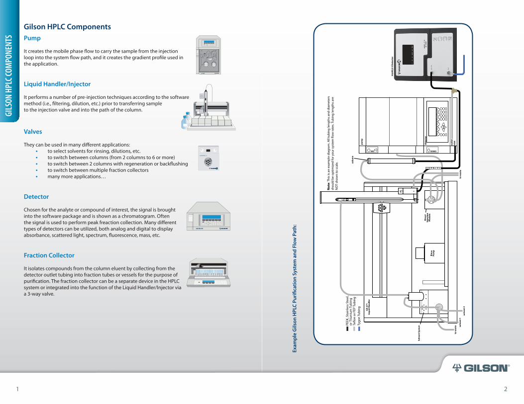
Pump
It creates the mobile phase flow to carry the sample from the injection loop into the system flow path, and it creates the gradient profile used in the application.
Liquid Handler/Injector
It performs a number of pre-injection techniques according to the softwaremethod (i.e., filtering, dilution, etc.) prior to transferring sample to the injection valve and into the path of the column.
Valves
They can be used in many different applications:• to select solvents for rinsing, dilutions, etc.• to switch between columns (from 2 columns to 6 or more) • to switch between 2 columns with regeneration or backflushing• to switch between multiple fraction collectors• many more applications…
Detector
Chosen for the analyte or compound of interest, the signal is brought into the software package and is shown as a chromatogram. Often the signal is used to perform peak freaction collection. Many different types of detectors can be utilized, both analog and digital to display absorbance, scattered light, spectrum, fluorescence, mass, etc.
Fraction Collector
It isolates compounds from the column eluent by collecting from the detector outlet tubing into fraction tubes or vessels for the purpose of purification. The fraction collector can be a separate device in the HPLC system or integrated into the function of the Liquid Handler/Injector via a 3-way valve.
Gilson HPLC Components
VALVEMATE® IIVALVE ACTUATOR
UV/VIS-151®
321 PUMP
GILS
ON H
PLC C
OMPO
NENT
S
Exam
ple
Gils
on H
PLC
Puri
ficat
ion
Syst
em a
nd F
low
Pat
h:
1 2
4 5
®
Troubleshooting - Getting Started
General Guidelines
Determine what the source of problem(s) is/are by identifying potential areas contributing to the problem.
• Take a moment to observe your system at the time of the problem to record some initial findings before moving on.
• The checklist on the next page will assist you.
When you are ready to try solutions, try one solution at a time – not several.
• It maybe more time consuming, but the real problem will be uncovered.• Uncovering the true problem will save you time by knowing what it is and developing
a plan on how to prevent it from happening again.
Check each part of the system independently.
• Verify general function of each component to identify problem areas.• Start verification with the pumping system and work through the flow path to identify
each component is operating optimally.
Perform a blank injection.
• Visually watch this injection to verify proper operation of each hardware component.• Verify the data signal shows normal baseline noise and contains no significant
compound absorbance.
TROU
BLES
HOOT
ING-
GETT
ING
STAR
TED
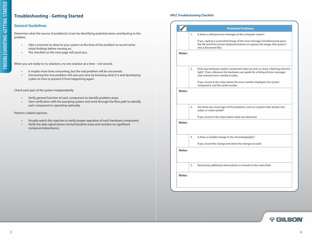
Potential Problems
1. Is there a software error message on the computer screen?
If yes, capture a screenshot/image of the error message (simultaneously press the ‘Alt’ and Print Screen’ keyboard buttons to capture the image, then paste it into a document file).
Notes:
2. Does any hardware system component show an error or show a flashing red error light? If yes, reference the hardware user guide for a listing of error messages and common error numbers/codes.
If yes, record in the notes below the error number displayed, the system component, and the serial number
Notes:
3. Are there any visual signs of the problems, such as a system leak, broken test tubes, or a bent probe?
If yes, record in the notes below what was observed.
Notes:
4. Is there a notable change in the chromatography?
If yes, record the change and when the change occured.
Notes:
5. Record any additional observations or remarks in the notes field.
Notes:
3 4
HPLC Troubleshooting Checklist
6 7
®
Isolating & Identifying Problems
Software
In general, software that is programmed to run your HPLC system can be a potential source of problems, and with a few easy troubleshooting tips, you can isolate the potential source to help identify where the problem exists.
Error Messages & Log File
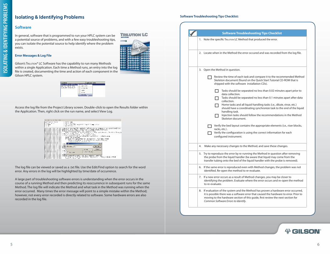
Gilson’s Trilution® LC Software has the capability to run many Methods within a single Application. Each time a Method runs, an entry into the log file is created, documenting the time and action of each component in the Gilson HPLC system.
Access the log file from the Project Library screen. Double-click to open the Results folder within the Application. Then, right click on the run name, and select View Log.
The log file can be viewed or saved as a .txt file. Use the Edit/Find option to search for the word error. Any errors in the log will be highlighted by time/date of occurrence.
A large part of troubleshooting software errors is understanding when the error occurs in the course of a running Method and then predicting its reoccurrence in subsequent runs for the same Method. The log file will indicate the Method and what task in the Method was running when the error occurred. Many times the error message will point to a simple mistake within the Method; however, not every error recorded is directly related to software. Some hardware errors are also recorded in the log file.
ISOL
ATIN
G &
IDEN
TIFY
ING
PROB
LEM
S
5 6
Software Troubleshooting Tips Checklist:
Software Troubleshooting Tips Checklist
1. Note the specific Trilution LC Method that produced the error.
2. Locate when in the Method the error occured and was recorded from the log file.
3. Open the Method in question.
Review the time of each task and compare it to the recommended Method Skeleton document (found on the Quick Start Tutorial CD-ROM that is shipped with the software installation CDs).
Tasks should be separated no less than 0.02 minutes apart prior to data collection.Tasks should be separated no less than 0.1 minutes apart after data collection.Home tasks and all liquid handling tasks (i.e., dilute, rinse, etc.) should have a coordinating synchronize task to the end of the liquid handling task.Injection tasks should follow the recommendations in the Method Skeleton document.
Verify the bed layout contains the appropriate elements (i.e., riser blocks, racks, etc.) .Verify the configuration is using the correct information for each configured instrument.
4. Make any necessary changes to the Method, and save these changes.
5. Try to reproduce the error by re-running the Method in question after removing the probe from the liquid handler (be aware that liquid may come from the transfer tubing onto the bed of the liquid handler with the probe is removed).
6. If the same error is reproduced even with Method changes, the problem was not identified. Re-open the method to re-evaluate.
7. If a new error occurs as a result of Method changes, you may be closer to identifying the problem. Evaluate where the error occurs and re-open the method to re-evaluate.
8. If evaluation of the system and the Method has proven a hardware error occurred, it is possible there was a software error that caused the hardware to error. Prior to moving to the hardware section of this guide, first review the next section for Common Software Errors to Identify.
8 9
®
Common Software Method Errors to Identify:
Problem Potential Cause Solution
Probe Bending
Missing synchronizes to home and liquid handling tasks.
Verify that all home and liquid handling tasks have a coordinating synchronize to end of task.
Tasks scheduled too close together (not according to the timelines suggested in the Method Skeleton document).
Space tasks at minimum:0.02 min apart prior to data collection0.1 min apart after data collection
Bed Layout uses incorrect elements.
Verify that riser blocks and rack risers have been added to the bed layout according to the placement on the liquid handler. Verify riser is/is not present by right-clicking on an element and selecting Hide. Enlarge the screen to display the underlying riser (if present). Right-click again and select Show All.
Z-Target Error on Liquid Handler
Task uses a z-depth that is too low for the liquid handler configuration to reach (current probe and clamp).
For configurations using a 125 mm probe and a clamp height > 175 mm, set the z-depth at 20 mm or higher from the bottom of the vessel/well and test.
Fraction Collection did not begin – No Fractions Collected Message
Incorrect order of tasks in Method.
Follow recommendations in Method Skeleton document to have the Fraction Collection Settings task or Set Fraction Site/Set Multiple Fraction Sites task at the correct time in the Method.
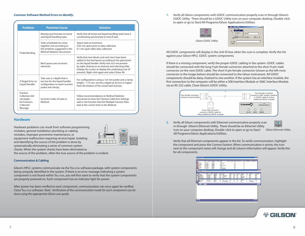
1. Verify all Gilson components with GSIOC communication properly scan in through Gilson’s GSIOC Utility. There should be a GSIOC Utility icon on your computer desktop. Double-click to open or go to Start/All Programs/Gilson Applications/Utilities.
All GSIOC components will display in the Unit ID box when the scan is complete. Verify this list against your Gilson HPLC GSIOC system components.
If there is a missing component, verify the proper GSIOC cabling in the system. GSIOC cables should be connected with the long 9-pin female connector attached to the short 9-pin male connector on the next GSIOC cable. The short 9-pin female connector (shown as the left-most connector in the image below) should be connected to the Gilson instrument. All GSIOC components should be daisy-chained to one another. If the system has an interface module, the first connection to the computer will be either a 508 Interface Module or 506C Interface Module via an RS-232 cable. Close Gilson’s GSIOC Utility.
2. Verify all Gilson components with Ethernet communication properly scan in through Gilson’s Ethernet Utility. There should be an Ethernet Utility icon on your computer desktop. Double-click to open or go to Start/ All Programs/Gilson Applications/Utilities.
Verify that all Ethernet components appear in the list. To verify communication, highlight the component and press the Connect button. When communication is active, the icon next to the component name will change and all column information will appear. Verify this for all components.
RS-232 GSIOC POWER
508INTERFACE MODULE
UV/VIS-151®
334 PUMP
333 PUMP
Gilson GSIOC Utility
7 8
Hardware
Hardware problems can result from software programming mistakes, general installation plumbing or cabling mistakes, improper preventive maintenance, or equipment malfunction requiring service/repair. Isolating and identifying the source of the problem is done by systematically eliminating a series of common system checks. When the system checks have been eliminated as the source of the problem, often the true source of the problem is evident.
Communication & Cabling
Gilson’s HPLC systems communicate via the Trilution software package, with system components being uniquely identified in the system. If there is an error message indicating a system component is not found within Trilution, you will first want to verify that the system components are properly powered on. Each component has an indicator light for power.
After power has been verified to each component, communication can once again be verified. Close Trilution software. Note: Verification of the communication mode for each component can be done using the appropriate Gilson user guide.
Gilson Ethernet Utility
10 11
®
If there is a missing component, verify the proper Ethernet cabling in the system with the router. All Ethernet components should be directly connected to the router. The computer should also be connected to the router.
If the Address column displays information other than an IP address of 192.XXX.X.XXX, then power off the Ethernet components. Close Gilson’s Ethernet Utility. Wait 5 full minutes, and then power the Ethernet components. Open Gilson’s Ethernet Utility, and reconnect the Ethernet components. If this sequence of events does not allow communication with all Ethernet components, you may also need to reset the router via a small button located next to the power connection on the router.
Close Gilson’s Ethernet Utility.
Misalignment/Offset
Visual observation of the system indicates if there is a misalignment or offset that needs to be corrected on the Gilson liquid handler:
• Probe is bent• Further inspection of the probe shows the tip is not completely straight or free of burrs• Rack is askew on the platform• Inspection of the injection port shows the probe has hit off-center
Each of Gilson’s liquid handler user guides details the process and programs used to properly align or offset to correct any X, Y positioning issues. If you do not have the tools indicated in the user guide, you may want to call a Gilson Service Representative to assist with this process.
Component Malfunction
Gilson hardware products are reliable and rugged, but due to the general nature of hardware over time, there may be a malfunction that occurs within the life of the product. The key to understanding when there is a malfunction is very important, and every Gilson hardware product will provide clues on the potential problem. The clues each Gilson hardware product provides is directly related to knowing answers to the questions on the next page.
The information you capture and record in the checklist is very important to have when contacting a Gilson Service Representative. Your call will be the next step in order to fully identify and work on the best solution to the situation.
Maintenance
A routine maintenance program on Gilson’s hardware systems is intended to keep your laboratory operational without needing to keep track of instrument maintenance. Gilson, Inc. has programs to optimize instrumentation life and optimize performance.
The purpose of a preventive maintenance program is to schedule and replace wearable instrument parts just prior to the end of their life cycle, allowing Gilson instrumentation to continue running optimally and without unscheduled disruption to your laboratory operations. Depending on your Gilson HPLC system components and rate of use, maintenance is scheduled every six months to one year.
Two other options are available to assist you with maintenance on your Gilson system:
• Extended warranties lengthen the maintenance period of your Gilson system from the initial purchase.
• Rebuilt exchange may be available for some system components, allowing a rebuilt item to be available at a reduced cost when service is required.
Contact Gilson’s Customer Service Department or your local Gilson representative for additional information on Gilson’s maintenance options.
System
System problems can result from flow path and plumbing mistakes, pressure issues, and column chromatography problems. Isolating and identifying system problems can be accomplished by understanding the flow path and plumbing on the system, running some basic system checks, and understanding some basic column chromatography problems that are inherent to HPLC.
9 10
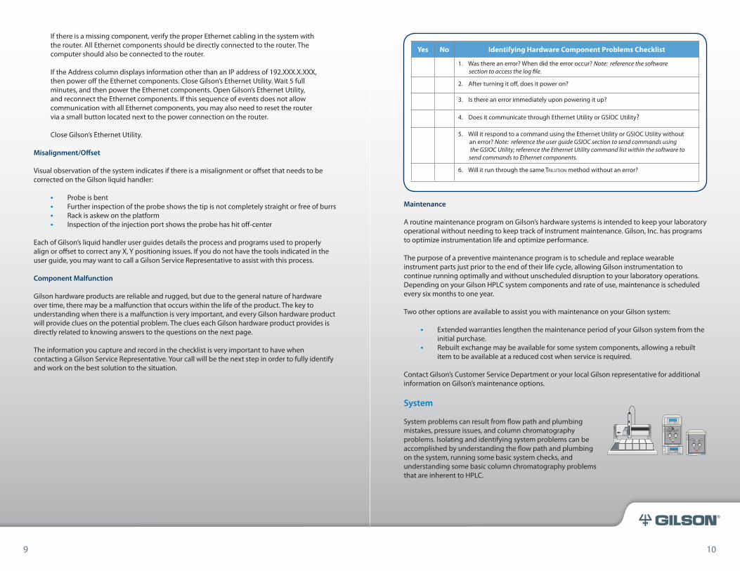
Yes No Identifying Hardware Component Problems Checklist
1. Was there an error? When did the error occur? Note: reference the software section to access the log file.
2. After turning it off, does it power on?
3. Is there an error immediately upon powering it up?
4. Does it communicate through Ethernet Utility or GSIOC Utility?
5. Will it respond to a command using the Ethernet Utility or GSIOC Utility without an error? Note: reference the user guide GSIOC section to send commands using the GSIOC Utility; reference the Ethernet Utility command list within the software to send commands to Ethernet components.
6. Will it run through the same Trilution method without an error?
UV/VIS-151®
334 PUMP
333 PUMP
12 13
®
System Initialization
Proper system care prior to operation is referred to as system initialization. This process ensures that the system is free of air, that all liquid lines are properly filled for accurate transfer, that the system fluid lines are put under pressure at the operating flow rate.
The Trilution software package should be used to initialize the system. This can be accomplished through a dedicated Method or through Manual Control.
Initialization considerations:
Homing Liquid Handler and Pump• Verifies that instrument is over a designated rinse location in order to eliminate
any remaining volume in the syringe or solvent pump
Priming• Aspirates and dispenses reservoir solvent to fill the transfer tubing from the
syringe or solvent pump to the probe
Rinsing• Inside Rinsing-Cleaning of the inside of the probe• Outside Rinsing-Cleaning of the outside of the probe• Injection Port Rinsing-Cleaning of one or more injection port locations on the
liquid handler bed
Mobile Phase Flow Rate Ramping• Ramping of the flow from the system mobile phase pumps over a certain period
of time until final flow rate is achieved (prevents pressure shock to the column)
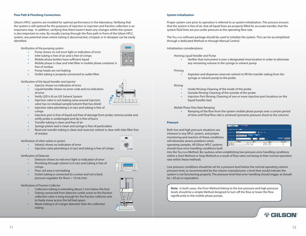
Pressure
Both low and high pressure situations are inherent in any HPLC system, and proper monitoring and reaction of these conditions will eliminate severe problems when operating samples. All Gilson HPLC systems should have error handling conditions built into the Trilution Method. Be cautious when establishing low pressure error handling conditions within a Start Method or Stop Method as a result of flow rates not being at their normal operation rate within these methods.
Low pressure conditions should be set for a pressure level below the normal operating column pressure level, as recommended by the column manufacturer; a level that would indicate the system is not functioning properly. The pressure level that error handling should trigger at should be >20 psi or equivalent.
Flow Path & Plumbing Connections
Gilson’s HPLC systems are installed for optimal performance in the laboratory. Verifying that the system is still optimal for the purposes of injection or injection and fraction collection is an important step. In addition, verifying that there haven’t been any changes within the system is also important to note. By visually tracing through the flow path in front of the Gilson HPLC system, any potential areas where tubing is disconnected, crimped, or in disrepair can be easily identified.
Verification of the pumping system• Pump shows no red error light or indication of error• Inlet tubing is free of air and is free of crimps• Mobile phase bottles have sufficient liquid• Mobile phase is clear and inlet filter in mobile phase container is
free of residue• Pump heads are not leaking• Outlet tubing is properly connected to outlet filter
Verification of the liquid handler and injector• Injector shows no indication of error• Liquid handler shows no error code and no indication
of error• Verify LED is lit on GX Solvent System• Injection valve is not leaking (area around injection
valve has no residual sample/solvent that has dried)• Injection valve plumbing is in tact and tubing is free of
crimps• Injection port is free of liquid and free of damage from probe; remove probe and
verify probe is undamaged and tip is free of burrs• Transfer tubing is clean and free of air• Syringe piston seal is clean and syringe is free of particulates• Reservoir transfer tubing is clean and reservoir solvent is clear with inlet filter free
of residue
Verification of other valves in system • Valve(s) shows no indication of error• Injection valve plumbing is in tact and tubing is free of crimps
Verification of Detector• Detector shows no red error light or indication of error• Plumbing through column is in tact and tubing is free of
crimps • Flow cell area is not leaking• Outlet tubing is connected to a union and not a back
pressure regulator for flows > 10 mL/min
Verification of Fraction Collector• Collection tubing is extending about 2 mm below the foot• Tubing connected from detector outlet union to the fraction
collection valve is long enough for the fraction collector arm to freely move across the full bed space
• Waste tubing is of a larger diameter than the collection tubing
321 PUMP
VALVEMATE® IIVALVE ACTUATOR
UV/VIS-151®
11 12
Note: in both cases, the Error Method linking to the low pressure and high pressure levels should be a simple Method designed to turn off the flow or lower the flow significantly to the mobile phase pumps.
14 15
®
Optimizing Fraction Collection
There are many modes available for isolating the compound(s) of interest. Optimal isolation or purification is performed when a combination of the following occurs:
• Collect as much compound as possible in the least amount of column eluent as possible
• Collect into the fewest number of fraction tubes per injection as possible• Collect the desired compound(s) into separate tubes• Collect to recover as much of the eluting compound as possible• Collect from as many complimentary data or detector sources for the compound of
interest as possible (see image below of complimentary fraction collection using UV detection - blue trace - and prepELS detection - orange trace).
Chromatography
Chromatography can vary based on the type of analysis being performed; analytical, semi-preparative, and preparative. Depending on the sample load, the type of column used, the solubility of the compound(s) in solution, sample matrix effect, etc. you may experience HPLC issues visible in the chromatography over the course of time. Changes in chromatography during routine analysis or purification can cost valuable time in the laboratory, and troubleshooting the most common chromatography problems can be challenging even for the most experienced chemist. In this section, we discuss four very common problems visible in chromatography and discuss potential areas to troubleshoot and investigate.
Some of the most common problems visible in chromatography are:
1. Shifting retention time2. No peaks3. Reduced peak size4. Poor peak shape
High pressure conditions should be set for a pressure level that is above the normal operating column pressure level, as recommended by the column manufacturer; a level that would indicate the system is not functioning properly AND a level that is safe from tubing failure.
Fraction Collection/Purification
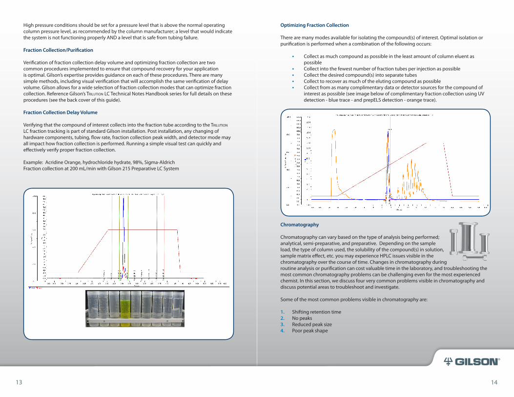
Verification of fraction collection delay volume and optimizing fraction collection are two common procedures implemented to ensure that compound recovery for your application is optimal. Gilson’s expertise provides guidance on each of these procedures. There are many simple methods, including visual verification that will accomplish the same verification of delay volume. Gilson allows for a wide selection of fraction collection modes that can optimize fraction collection. Reference Gilson’s Trilution LC Technical Notes Handbook series for full details on these procedures (see the back cover of this guide).
Fraction Collection Delay Volume
Verifying that the compound of interest collects into the fraction tube according to the Trilution LC fraction tracking is part of standard Gilson installation. Post installation, any changing of hardware components, tubing, flow rate, fraction collection peak width, and detector mode may all impact how fraction collection is performed. Running a simple visual test can quickly and effectively verify proper fraction collection.
Example: Acridine Orange, hydrochloride hydrate, 98%, Sigma-AldrichFraction collection at 200 mL/min with Gilson 215 Preparative LC System
13 14
16 17
®
Potential Causes Potential Solution
Temperature in the laboratory may impact the chromatography at the same time each day. Verify time retention time shifts for a daily pattern. Correlate this to a planned thermostat temperature change in the laboratory.
Can the time of the planned temperature change be modified in the thermostat?
If the temperature shift varies and is not predictable, then try using a column heater or water jacket to stabilize the chromatography elution.
Verify the flow rate has not changed and is accurate for your Method.
Measure the flow rate with a setting of 100% gradient on each pump head; testing each pump head separately. Also check the flow rate with a setting of 50% on each pump head. If the flow rate is not accurate, preventive maintenance may be required.
Verify if the retention time shift is the result of using a new column, a new lot of column, or a new manufacturer. Verify if the same column lot or manufacturer was used for prior analysis.
A new column may need additional time to equilibrate with mobile phase and injections of reference standard.
Column performance varies from lot to lot. Try another column with the same lot as the original lot.
Mobile phase that requires preparation (i.e. pH adjustment, modifiers) may need additonal time for adequate mixing before use.
Verify the correct mobile phase is being used on pump A and on pump B.
Prepare new mobile phase and allow sufficient equilibration time prior to injecting 3-5 standards for retention time observation.
Correlate the solvents to the Trilution LC software Method.
Proper and regular preventive maintenance on mobile phase pumps is essential to accurate flow rates and proper pump operation.
Perform a full preventive maintenance on each pump and pump head. Verify proper replacement of the inlet and outlet check valve, piston seal (appropriate type for mobile phase solvent used), bellows (if required), and outlet filter. Also check if inlet filters need to be replaced. Verify mobile flow rate on each pump head is constant and consistent at the gradient flow rate used in the software Method.
Trilution LC software Methods require linking of synchronize tasks to injection tasks. These synchronizes allow for efficient Method operation and reduction in retention time shifts.
Compare injection Method with Method Skeleton document to verify there is a synchronize task prior to data collection and after data collection (if doing fraction collection).
15 16
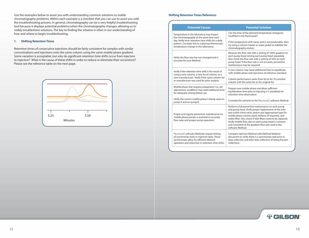
Shifting Retention Times Reference:Use the examples below to assist you with understanding common solutions to visible chromatography problems. Within each example is a checklist that you can use to assist you with the troubleshooting process. In general, chromatography can be a very helpful troubleshooting tool because it displays potential problems when the chromatography changes, allowing us to visibly troubleshoot solutions. The key to finding the solution is often in our understanding of how and where to begin troubleshooting.
1. Shifting Retention Times
Retention times of consecutive injections should be fairly consistent for samples with similar concentrations and injections onto the same column using the same mobile phase gradient. Some variation is acceptable, but why do significant retention time shifts occur from injection to injection? What is the cause of these shifts in order to reduce or eliminate their occurrence? Please see the reference table on the next page.
3.25 3.50Minutes
18 19
®
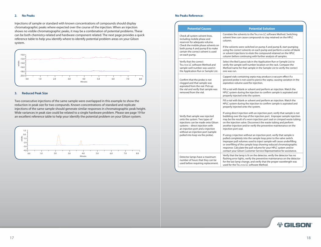
2. No Peaks
Injections of sample or standard with known concentrations of compounds should display chromatographic peaks where expected over the course of the injection. When an injection shows no visible chromatographic peaks, it may be a combination of potential problems. These can be both chemistry-related and hardware component related. The next page provides a quick reference table to help you identify where to identify potential problem areas on your Gilson system.
3. Reduced Peak Size
Two consecutive injections of the same sample were overlapped in this example to show the reduction in peak size for two compunds. Known concentrations of standard and replicate injections of the same sample should generate similar responses in chromatographic peak height. Wide variances in peak size could be related to a single hardware problem. Please see page 19 for an excellent reference table to help your identify the potential problem on your Gilson system.
1.0
0.0
-1.0
-2.0
-3.0
-4.00.0 1.0 2.0 3.0 4.0
Minutes5.0 6.0 7.0 8.0
mVo
lts
17 18
-10.0
-12.0
-14.0
-16.0
-18.0
-20.00.0 1.0 2.0 3.0 4.0
Minutes5.0 6.0 7.0 8.0
mVo
ltsNo Peaks Reference:
Potential Causes Potential Solution
Check all system solvent lines, including mobile phase and reservoir for adequate volume. Check the mobile phase solvents on both pump A and pump B to make certain the correct solvent is used on each pump.
Correlate the solvents to the Trilution LC software Method. Switching solvent lines can cause compounds to stay retained on the HPLC column.
If the solvents were switched on pump A and pump B, start pumping using the correct solvents on each pump and perform a series of blank or solvent injections to elute the compound retained on the HPLC column before continuing with further analysis of samples.
Verify that the correct Trilution LC software Method and sample well number was used in the Application Run or Sample List.
Select the Bed Layout tab in the Application Run or Sample List to verify the sample well number location on the rack. Compare the Method name for that sample in the Sample List to verify the correct one was run.
Confirm that the probe is not clogged and that sample was aspirated from the vial. Pick up the vial and verify that sample was removed from the vial.
Capped vials containing septa may produce a vacuum effect if a grooved probe is not used to pierce the septa, causing variation in the aspiration volume used for injection.
Fill a vial with blank or solvent and perform an injection. Watch the HPLC system during the injection to confirm sample is aspirated and properly injected onto the system.
Verify that sample was injected onto the system. Two types of injections can be made onto Gilson systems – direct injection with an injection port and z-injection without an injection port (sample pulled into loop via the probe).
Fill a vial with blank or solvent and perform an injection. Watch the HPLC system during the injection to confirm sample is aspirated and properly injected onto the system.
If using direct injection with an injection port, verify that sample is not bubbling over the top of the injection port. Improper sample injection may be the result of a worn injection port seal or crimped waste tubing on the injection valve. Disconnect the waste tubing and perform another injection and/or verify the preventive maintenance on the injection port seal.
If using z-injection without an injection port, verify that sample is pulled completely into the sample loop prior to the valve switch. Improper pull volumes used to inject sample will cause underfilling or overfilling of the sample loop showing reduced chromatographic response. Calculate the pull volume for your HPLC system and/or contact your Gilson Customer Service Representative for assistance.
Detector lamps have a maximum number of hours that they can be used before requiring replacement.
Verify that the lamp is lit on the detector, verify the detector has no flashing error lights, verify the preventive maintenance on the detector for the last lamp change, and verify that the proper wavelength was used for the Trilution LC software Method.
20 21
®
Poor Peak Shape Tips
Sample solvent, rinse solvent, and mobile phase solvents should be compatible. Solubility of sample with system solvents assures that efficient liquid handling with minimal carryover is achieved.
Peak fronting may be caused by using the wrong sample solvent. Make certain that the mobile phase, sample solvent, and reservoir solvent are similar in chemistry. Sample overload may be causing the fronting appearance. Check the load specifications listed for the HPLC column being used. Verify that overloading is not causing the undesirable peak shape.
Peak tailing is commonly seen, indicating column-sample interaction issues. Interfering peaks may be a source of tailing, and modifying the gradient chemistry or mobile phase solvent may separate the peaks. Changing the column chemistry may also eliminate the tailing. Tailing may also be reduced by using a mobile phase additive, such as triethylamine (TEA) and/or by changing the pH.
Column life may vary with the number of injections, the column lot, the type of column packing, the routine maintenance and cleaning, etc. Column cleaning can be an efficient means of extending column life. Column manufacturers may have recommendations for column cleaning procedures. Integrating column cleaning into your Gilson HPLC system is a simple and efficient way to automate this process during analysis.
Use a back pressure regulator on the detector outlet tubing under analytical flow rate conditions. Out gassing of mobile phase solvents may cause irregular peak shape.
80.0
60.0
40.0
20.0
0.00.0 1.0 2.0 3.0
PN:1
PN:2
Minutes4.0 5.0 6.0
mVo
lts
19 20
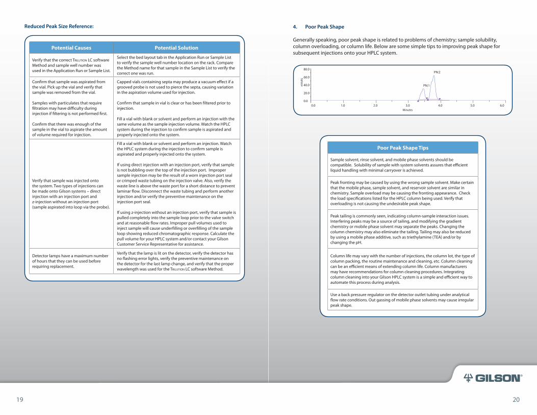
4. Poor Peak Shape
Generally speaking, poor peak shape is related to problems of chemistry; sample solubility, column overloading, or column life. Below are some simple tips to improving peak shape for subsequent injections onto your HPLC system.
Potential Causes Potential Solution
Verify that the correct Trilution LC software Method and sample well number was used in the Application Run or Sample List.
Select the bed layout tab in the Application Run or Sample List to verify the sample well number location on the rack. Compare the Method name for that sample in the Sample List to verify the correct one was run.
Confirm that sample was aspirated from the vial. Pick up the vial and verify that sample was removed from the vial.
Samples with particulates that require filtration may have difficulty during injection if filtering is not performed first.
Confirm that there was enough of the sample in the vial to aspirate the amount of volume required for injection.
Capped vials containing septa may produce a vacuum effect if a grooved probe is not used to pierce the septa, causing variation in the aspiration volume used for injection.
Confirm that sample in vial is clear or has been filtered prior to injection.
Fill a vial with blank or solvent and perform an injection with the same volume as the sample injection volume. Watch the HPLC system during the injection to confirm sample is aspirated and properly injected onto the system.
Verify that sample was injected onto the system. Two types of injections can be made onto Gilson systems – direct injection with an injection port and z-injection without an injection port (sample aspirated into loop via the probe).
Fill a vial with blank or solvent and perform an injection. Watch the HPLC system during the injection to confirm sample is aspirated and properly injected onto the system.
If using direct injection with an injection port, verify that sample is not bubbling over the top of the injection port. Improper sample injection may be the result of a worn injection port seal or crimped waste tubing on the injection valve. Also, verify the waste line is above the waste port for a short distance to prevent laminar flow. Disconnect the waste tubing and perform another injection and/or verify the preventive maintenance on the injection port seal.
If using z-injection without an injection port, verify that sample is pulled completely into the sample loop prior to the valve switch and at reasonable flow rates. Improper pull volumes used to inject sample will cause underfilling or overfilling of the sample loop showing reduced chromatographic response. Calculate the pull volume for your HPLC system and/or contact your Gilson Customer Service Representative for assistance.
Detector lamps have a maximum number of hours that they can be used before requiring replacement.
Verify that the lamp is lit on the detector, verify the detector has no flashing error lights, verify the preventive maintenance on the detector for the last lamp change, and verify that the proper wavelength was used for the Trilution LC software Method.
Reduced Peak Size Reference:

22 23
®
Training
Sometimes HPLC problems are a direct result of not knowing how to run the system most efficiently, how to make simple modifications to software Methods or how to optimize the use of your system in the laboratory. Training can often solve these problems and answer additional questions users have on their Gilson HPLC system.
Gilson’s Knowledge Center offers a wide variety of complimentary training options, web-based training options, and workshop/classroom training options. In addition, a basic system familiarization is provided at system install with your Gilson representative. To inquire about Gilson’s education and training opportunities: Visit our website: http://www.gilson.com to access our full education and training program within our automated instrumentation section.
Tel: 608-836-1551 or 800-445-7661 [email protected] 3000 Parmenter Street Middleton, WI 53562
Daily Use of System
General understanding of your Gilson HPLC system and how it is programmed to operate can lead to its efficient use in your laboratory for a few users or for many users. A short list of five key topics is outlined below. These topics are essential for every user to understand for optimal daily use of the system. Learning these basic topics doesn’t take much time - just a few short hours with a Gilson representative or with additional training.
1. Running samples – using a pre-defined Sample List2. Creating/Modifying a Sample List3. Using the Sample List buttons to override the running Method4. Operating the system using Manual Control5. Basic Navigation within Trilution LC – locating Methods and Chromatographic Data
Method Creation & Optimization
Users who are interested in optimizing their Gilson system will find additional training an efficient means of learning how to adjust Trilution LC Methods. With an understanding of how your current Methods operate, easy creation of additional Methods from these will allow you a chance to optimize your system for current and future analysis. By focusing time on what you would like to do in your application, training can focus on the tasks and capabilities within the Method.
Understanding how to use variables efficiently, how to create flexible mobile phase gradients and flexible fraction collection, how to optimize fraction collection – these are all topics that can assist you to more efficiently use your Gilson HPLC system for your current and future applications.
Computer
Eliminating potential sources of HPLC problems also means taking a look at the computer operating Gilson’s Trilution LC Software. Verifying that the specifications match with recommendations, verifying setup of the user rights/permissions on the computer, etc. are all routine checks that can be done when problems related to system operation are in question.
Specifications
Computer specifications are listed for each version of Trilution LC software in the Installation Guide within the Trilution LC media ( i.e. multi-CD software case). Specifications are also listed on Gilson’s public website to ensure optimal performance of the operating software.
Access
Installation of Trilution LC Software is documented in the Installation Guide. Installation does require administrator computer access. Separate user access levels can be set within Trilution LC to limit software access to specific functions based on group definition.
Automatic Updates
It is recommended that automatic updates be turned off on computers operating Trilution LC Software. Disrupting the collection of chromatographic data or operation of the Gilson system with automatic operating system updates is not recommended.
Rebooting
Regular rebooting of the computer running Trilution LC Software is recommended on a 24-hour basis to restore the computer RAM and achieve optimal daily performance.
Maintenance
Regular maintenance of Trilution LC Software is recommended for version 1.4 using the supplied Trilution LC 1.4 Backup Utility. Maintenance of subsequent versions is accomplished by using the Archive function within the Results screen. Use of the Archive function is described in the Help menu within Trilution LC and on the Quick Start Tutorial CD-ROM by viewing the Import Export document.
Laboratory/Facility
It is possible that some HPLC problems are related to issues within the laboratory or facility. While this guide is not intended to solve these problems, it is recommended to at least understand that problems could result from laboratory or facility conditions the Gilson HPLC is operating within.
21 22
24 25
®
Some of these problems can be identified by verifying:
Power
Power surges may occur causing intermittent communication with hardware components.
Temperature/Humidity
Large shifts may cause chromatography problems.
Waste Collection
Verify that all waste fluid lines from the HPLC system run vertically to an appropriate collection container.
Areas where there is horizontal collection within the waste fluid lines cause irregular waste collection and potential backups.
System Cart
Enough space should be available to allow for proper waste collection and access to the HPLC system.
The system cart should be level and be capable of accommodating the weight of the HPLC system components.
Understanding CarryoverHow Solvent Selection Affects Carryover
Sample type, sample matrix and sample concentration all contribute to carryover. Select a sample solvent in which the sample and matrix are readily soluble at the concentration you will be using. Samples that are readily soluble are easily rinsed from the injection valve, injection probe and tubing.
If the sample concentration you are using is minimally soluble, extensive rinses of the probe, transfer tubing, injection port, and injection valve are necessary to reduce carryover.
How Optimizing Rinse and Injection Procedures Reduces Carryover
Although the sample matrix cannot be changed, the rinse solvent can be optimized for solubility. Rinse solvents must be compatible with the system mobile phase and should not affect or impact chromatographic separation. For mass spectrometers, the rinse solvent cannot interfere with ionization. Optimizing your system injection and rinse procedures, as described in the following paragraphs, will help reduce the carryover in your system.
After the injection port has been rinsed, move the probe to the rinse station (optimally a flowing rinse station) and rinse the probe by aspirating and dispensing 75% of the syringe or transfer tubing volume three times at a speed of 10 mL/min.
UNDE
RSTA
NDIN
G CA
RRYO
VER
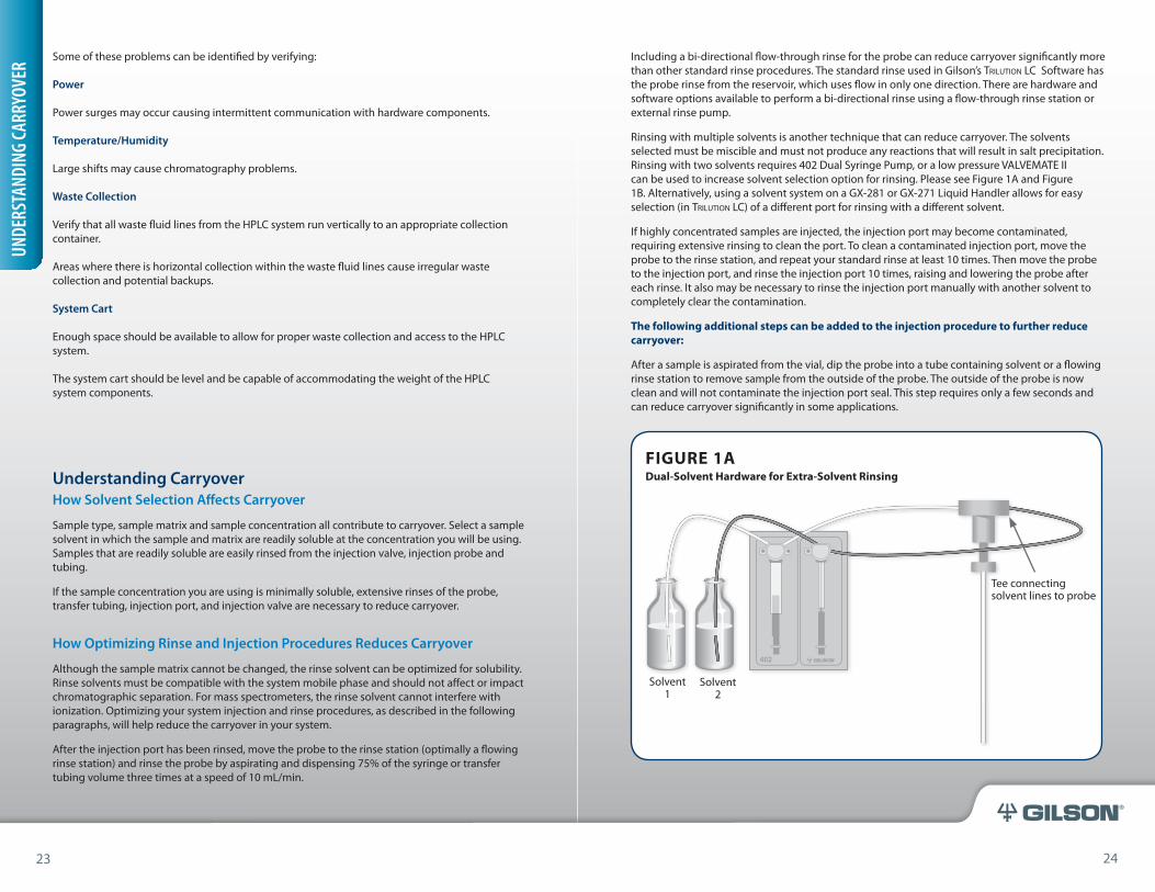
Solvent 1
Solvent 2
Tee connecting solvent lines to probe
FIGURE 1ADual-Solvent Hardware for Extra-Solvent Rinsing
23 24
Including a bi-directional flow-through rinse for the probe can reduce carryover significantly more than other standard rinse procedures. The standard rinse used in Gilson’s Trilution LC Software has the probe rinse from the reservoir, which uses flow in only one direction. There are hardware and software options available to perform a bi-directional rinse using a flow-through rinse station or external rinse pump.
Rinsing with multiple solvents is another technique that can reduce carryover. The solvents selected must be miscible and must not produce any reactions that will result in salt precipitation. Rinsing with two solvents requires 402 Dual Syringe Pump, or a low pressure VALVEMATE II can be used to increase solvent selection option for rinsing. Please see Figure 1A and Figure 1B. Alternatively, using a solvent system on a GX-281 or GX-271 Liquid Handler allows for easy selection (in Trilution LC) of a different port for rinsing with a different solvent.
If highly concentrated samples are injected, the injection port may become contaminated, requiring extensive rinsing to clean the port. To clean a contaminated injection port, move the probe to the rinse station, and repeat your standard rinse at least 10 times. Then move the probe to the injection port, and rinse the injection port 10 times, raising and lowering the probe after each rinse. It also may be necessary to rinse the injection port manually with another solvent to completely clear the contamination.
The following additional steps can be added to the injection procedure to further reduce carryover:
After a sample is aspirated from the vial, dip the probe into a tube containing solvent or a flowing rinse station to remove sample from the outside of the probe. The outside of the probe is now clean and will not contaminate the injection port seal. This step requires only a few seconds and can reduce carryover significantly in some applications.
26 27
®
How Probe Selection Affects Carryover
The internal and external diameter of the probe affects the amount of sample that adheres to the inside and outside of the probe after the sample is dispensed. Using probes with constant internal diameters helps minimize the amount of sample that adheres to the inside of the probe. Select a probe with the smallest possible internal and external diameter that is made from a material that does not have an affinity for your sample or sample matrix. Probes with constricted tips can increase carryover under certain conditions. (See Figure 2 below.)
Sample
Sample being pushed through probe, and the affects of laminar flow
Area where test material can cling; bi-directional rinsing can help
Flow
FIGURE 2Constricted-Tip Probes
Inje
ctio
n F
oll
owin
g 9
80 p
pb
An
thra
cen
e Sp
ike
Inje
ctio
n
Average % Carryover
0.00
00
0.02
00
0.04
00
0.06
00
0.08
00
0.10
00
0.12
00
MeO
H b
lan
k 3
MeO
H b
lan
k 2
MeO
H b
lan
k 1
0.1051
0.0929
0.0345
0.0222
0.0206
0.0180
0.0253
0.0224
0.0063
0.0074
0.0082
0.0086
0.0130
0.0063
0.0000
0.0046
0.0053
0.0059
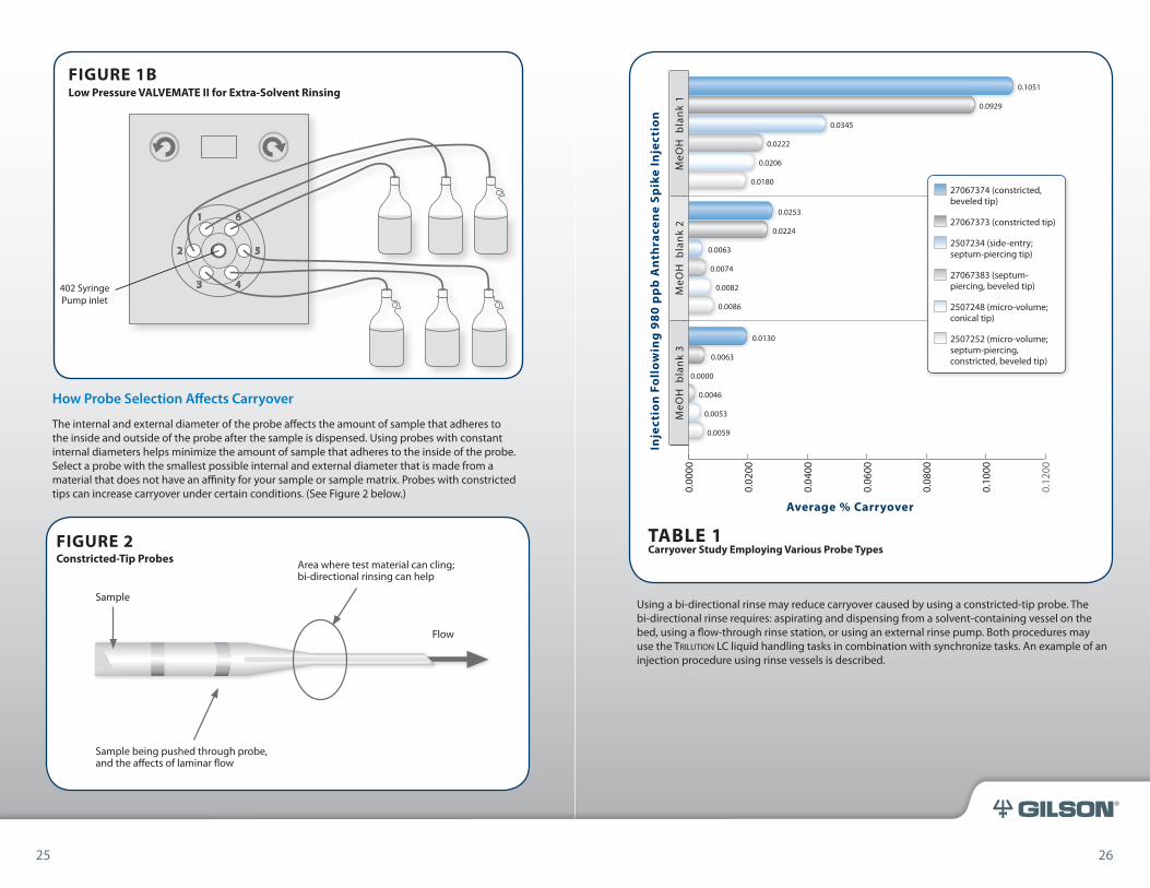
27067374 (constricted, beveled tip)
27067373 (constricted tip)
2507234 (side-entry; septum-piercing tip)
27067383 (septum-piercing, beveled tip)
2507248 (micro-volume; conical tip)
2507252 (micro-volume; septum-piercing, constricted, beveled tip)
TABLE 1 Carryover Study Employing Various Probe Types
Using a bi-directional rinse may reduce carryover caused by using a constricted-tip probe. The bi-directional rinse requires: aspirating and dispensing from a solvent-containing vessel on the bed, using a flow-through rinse station, or using an external rinse pump. Both procedures may use the Trilution LC liquid handling tasks in combination with synchronize tasks. An example of an injection procedure using rinse vessels is described.
25 26
FIGURE 1BLow Pressure VALVEMATE II for Extra-Solvent Rinsing
402 Syringe Pump inlet
402 Syringe Pump inlet
28 29
®
Rinse Vial Procedure
1. Move arm to rinse vial location. Sychronize to end of task.
2. Move arm to proper rinse vial z-height. Sychronize to end of task.
3. Aspirate 500 µL of rinse vial solvent at 6 mL/min. Sychronize to end of task.
4. Move arm to proper rinse vial z-height. Sychronize to end of task.
5. Dispense 500 µL of rinse vial solvent at 6 mL/min. Sychronize to end of task.
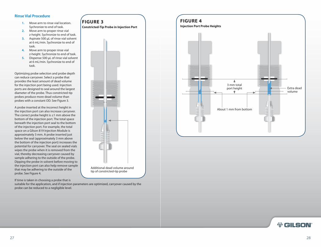
Optimizing probe selection and probe depth can reduce carryover. Select a probe that provides the least amount of dead volume for the injection port being used. Injection ports are designed to seal around the largest diameter of the probe. Thus constricted-tip probes produce more dead volume than probes with a constant OD. See Figure 3.
A probe inserted at the incorrect height in the injection port can also increase carryover. The correct probe height is ≤1 mm above the bottom of the injection port. The total space beneath the injection port seal to the bottom of the injection port. For example, the total space on a Gilson 819 Injection Module is approximately 3 mm. A probe inserted just below the seal (approximately 3 mm above the bottom of the injection port) increases the potential for carryover. The seal on sealed vials wipes the probe when it is removed from the vial, thereby decreasing carryover caused by sample adhering to the outside of the probe. Dipping the probe in solvent before moving to the injection port can also help remove sample that may be adhering to the outside of the probe. See Figure 4.
If time is taken in choosing a probe that is suitable for the application, and if injection parameters are optimized, carryover caused by the probe can be reduced to a negligible level.
Additional dead volume around tip of constricted-tip probe
FIGURE 3Constricted-Tip Probe in Injection Port
3 mm total port height
About 1 mm from bottom
Extra dead volume
FIGURE 4Injection Port Probe Heights
27 28
30 31
®
How Plumbing Affects Carryover
Sample also comes in contact with the transfer tubing, which can potentially cause carryover. Transfer tubing selection should be optimized for the sample volumes being injected. (See page 31 for transfer tubing recommendations.) The further sample moves through the transfer tubing, the greater the chance for contamination. Sample should never travel completely through the transfer tubing into the syringe or solvent system. Once sample has entered the syringe it is very difficult to rinse out. Additionally, leaking syringes can increase carryover and should be replaced.
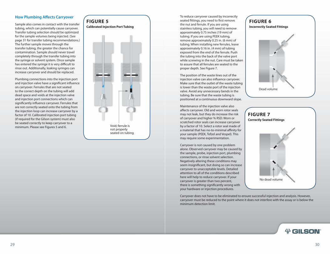
Plumbing connections into the injection port and injection valve have a significant influence on carryover. Ferrules that are not seated to the correct depth on the tubing will add dead space and voids at the injection valve and injection port connections which can significantly influence carryover. Ferrules that are not correctly seated onto the tubing from the injection loop can increase carryover by a factor of 10. Calibrated injection port tubing (if required for the Gilson system) must also be seated correctly to keep carryover to a minimum. Please see Figures 5 and 6. Void; ferrule is
not properly seated on tubing
FIGURE 5Calibrated Injection Port Tubing
To reduce carryover caused by incorrectly seated fittings, you need to first remove the nut and ferrule. If you are using stainless tubing, you will need to remove approximately 0.75 inches (19 mm) of tubing. If you are using PEEK tubing, remove approximately 0.25 in. (6 mm) of tubing. When installing new ferrules, leave approximately 0.16 in. (4 mm) of tubing exposed from the end of the ferrule. Push the tubing into the back of the valve port while screwing in the nut. Care must be taken to assure that all ferrules are seated to the proper depth. See Figure 7.
The position of the waste lines out of the injection valve can also influence carryover. Make sure that the outlet of the waste tubing is lower than the waste port of the injection valve. Avoid any unnecessary bends in the tubing. Be sure that the waste tubing is positioned at a continuous downward slope.
Maintenance of the injection valve also affects carryover. Old and worn rotor seals may not leak, but they do increase the risk of carryover and higher % RSD. Worn or scratched rotor seals can increase carryover by a factor of 10. Select a rotor seal made of a material that has no-to-minimal affinity for your sample (PEEK, Tefzel and Vespel). This may require some experimentation.
Carryover is not caused by one problem alone. Observed carryover may be caused by the sample, probe, injection port, plumbing connections, or rinse solvent selection. Negatively altering these conditions may seem insignificant, but doing so can increase carryover to unacceptable levels. Detailed attention to all of the conditions described here will help to reduce carryover. If your carryover is greater than two percent, there is something significantly wrong with your hardware or injection procedures.
Carryover does not have to be eliminated to ensure successful injection and analysis. However, carryover must be reduced to the point where it does not interfere with the assay or is below the minimum detection limit.
Dead volume
FIGURE 6Incorrectly Seated Fittings
No dead volume
FIGURE 7Correctly Seated Fittings
29 30
32 33
®
Carryover ranging from 0.1% to 0.01% is reasonable and should be achievable in your routine, daily operations. With added precautions, carryover of less than 0.005% can be achieved. These added precautions may slightly increase time per injection, but the increase in time will not be significant if your chromatography separation time is greater than two minutes.
This section does not address carryover caused by sample affinity for probes, tubing, injection port seals or injector rotor seals. This phenomenon will require changing the material of one or more of your hardware components. The solution to reducing carryover is whatever works best for the sample you are using.
Probe & Transfer Tubing Selection
Transfer Tubing Selection
Choosing the correct volume of transfer tubing is based on the syringe size when using a Gilson 402 Syringe Pump. Choose transfer tubing that is at least as large as the syringe to prevent sample from entering the syringe.
When using a solvent system, Choose a volume of transfer tubing that is close to the largest volume to be regularly aspirated and dispensed.
Gilson Probe Product Number IdentificationGilson probes are laser engraved with their product number on the collar of each probe providing a quick and effortless identification reference for re-ordering and support.
PROB
E & TR
ANSF
TER
TUBI
NG SE
LECT
ION
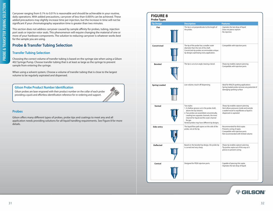
Tip Design Description Features
Flat The tip is cut perpendicular to the length of the probe.
· Aspirates the last drop of liquid· Does not pierce septum· No injection
Constricted The tip of the probe has a smaller outer diameter than the rest of the shaft. Constricted-tip probes accommodate unique tip designs optimizing every application.
· Compatible with injection ports
Beveled The tip is cut at an angle, leaving a bevel. · Sharp tip enables septum-piercing· Compatible with injection ports
Spring Loaded Low volume, touch-off dispensing. · Ideal for MALDI spotting applications· Spring loaded probe removes any potential of damaging spotting surface
Vented Two styles: 1. A shallow groove cut in the probe shaft,
above the tip (shown).2. Two probes are assembled concentrically,
creating two separate channels, the inner channel for liquid and the outer channel for gas.
Vented probes may have different tip designs.
· Sharp-tip enables septum-piercing· Vent allows pressures inside and outside
a sealed vessel to equilibrate as liquid is dispensed or aspirated
Side-entry The liquid flow path opens on the side of the probe, not at the tip.
· Recommended for thick septa· Prevents coring of septa· Compatible with injection ports · Not recommended with limited volume
Deflected Based on the beveled tip design, the probe tip is curved and very sharp.
· Sharp-tip enables septum-piercing· Tip pushes septa out of the way as it pierces to prevent coring
Conical Designed for PEEK injection ports. · Capable of piercing thin septa· Aspirates the last drop of liquid
31 32
FIGURE 8Probe Types
Probes
Gilson offers many different types of probes, probe tips and coatings to meet any and all application needs providing solutions for all liquid handling requirements. See Figure 8 for more details.
34 35
®
Troubleshooting Carryover
1. Is carryover greater than 0.02 %?
• The sample is not soluble enough in the rinse solvent.Switch to a solvent in which the sample is readily soluble, or try using a dual-solvent rinse. (See Figure 1)
• The sample has affinity for the proble tubing injection port or rotor seal. If possible try switching to a Vespel Tefzel or PEEK rotor seal. However, if the system has been working with this sample, don’t change the rotor seal type.
• The injector rotor seal may be scratched or damaged. When in doubt, replace the rotor seal.
• Ferrules may not be seated correctly in the injection valve.The tubing connections into the injection valve from the sample loop and from the injection valve to the column must be perfect. If unsure, remove and replace all fittings. Push the tubing to the back of the port. Once the tubing is positioned, slide the ferrule and nut into the injection port while holding the tubing firmly against the back of the port. (See Figures 5–7)
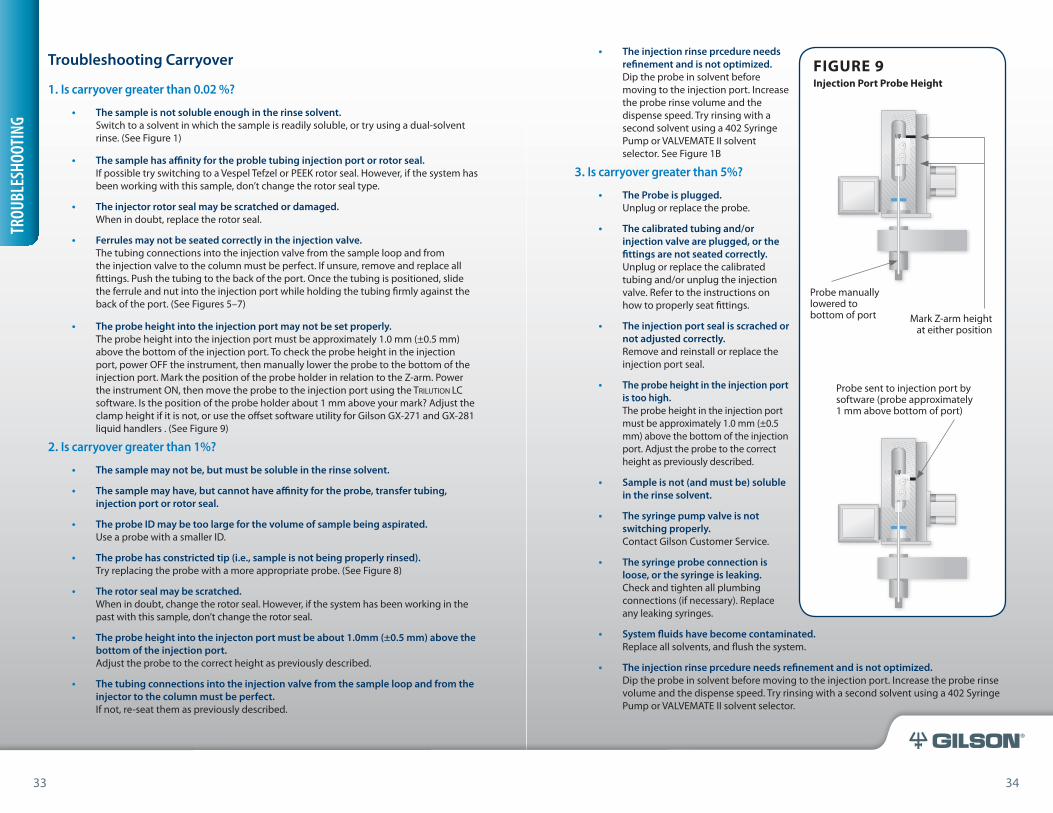
• The probe height into the injection port may not be set properly. The probe height into the injection port must be approximately 1.0 mm (±0.5 mm) above the bottom of the injection port. To check the probe height in the injection port, power OFF the instrument, then manually lower the probe to the bottom of the injection port. Mark the position of the probe holder in relation to the Z-arm. Power the instrument ON, then move the probe to the injection port using the Trilution LC software. Is the position of the probe holder about 1 mm above your mark? Adjust the clamp height if it is not, or use the offset software utility for Gilson GX-271 and GX-281 liquid handlers . (See Figure 9)
2. Is carryover greater than 1%?
• The sample may not be, but must be soluble in the rinse solvent.
• The sample may have, but cannot have affinity for the probe, transfer tubing, injection port or rotor seal.
• The probe ID may be too large for the volume of sample being aspirated. Use a probe with a smaller ID.
• The probe has constricted tip (i.e., sample is not being properly rinsed).Try replacing the probe with a more appropriate probe. (See Figure 8)
• The rotor seal may be scratched. When in doubt, change the rotor seal. However, if the system has been working in the past with this sample, don’t change the rotor seal.
• The probe height into the injecton port must be about 1.0mm (±0.5 mm) above the bottom of the injection port.Adjust the probe to the correct height as previously described.
• The tubing connections into the injection valve from the sample loop and from the injector to the column must be perfect.If not, re-seat them as previously described.
TROU
BLES
HOOT
ING
• The injection rinse prcedure needs refinement and is not optimized.Dip the probe in solvent before moving to the injection port. Increase the probe rinse volume and the dispense speed. Try rinsing with a second solvent using a 402 Syringe Pump or VALVEMATE II solvent selector. See Figure 1B
3. Is carryover greater than 5%?
• The Probe is plugged.Unplug or replace the probe.
• The calibrated tubing and/or injection valve are plugged, or the fittings are not seated correctly. Unplug or replace the calibrated tubing and/or unplug the injection valve. Refer to the instructions on how to properly seat fittings.
• The injection port seal is scrached or not adjusted correctly. Remove and reinstall or replace the injection port seal.
• The probe height in the injection port is too high. The probe height in the injection port must be approximately 1.0 mm (±0.5 mm) above the bottom of the injection port. Adjust the probe to the correct height as previously described.
• Sample is not (and must be) soluble in the rinse solvent.
• The syringe pump valve is not switching properly. Contact Gilson Customer Service.
• The syringe probe connection is loose, or the syringe is leaking. Check and tighten all plumbing connections (if necessary). Replace any leaking syringes.
• System fluids have become contaminated. Replace all solvents, and flush the system.
• The injection rinse prcedure needs refinement and is not optimized.Dip the probe in solvent before moving to the injection port. Increase the probe rinse volume and the dispense speed. Try rinsing with a second solvent using a 402 Syringe Pump or VALVEMATE II solvent selector.
Mark Z-arm height at either position
Probe manually lowered to bottom of port
Probe sent to injection port by software (probe approximately 1 mm above bottom of port)
FIGURE 9Injection Port Probe Height
33 34
36 37
®
4. Do you want carryover to be less than 0.01%? Can you accurately measure this?
• You may need to dip the probe into a flowing rinse before and after moving to the injection port.
• Dual-solvent rinsing may be necessary. Install a 402 Dual Syringe Pump or a VALVEMATE II solvent selector.
• The sample must be soluble in the rinse solvent.• All fittings into the valve must be seated to the proper depth.
Troubleshooting Hardware Components
Troubleshooting often refers to a standard set of checks that are performed on a specific hardware component identified and isolated with the problem. The problem is often related to unexpected performance. This section details specific troubleshooting that can be accomplished on each main component in a Gilson HPLC system. Refer to this section often once you have identified a hardware problem exists.
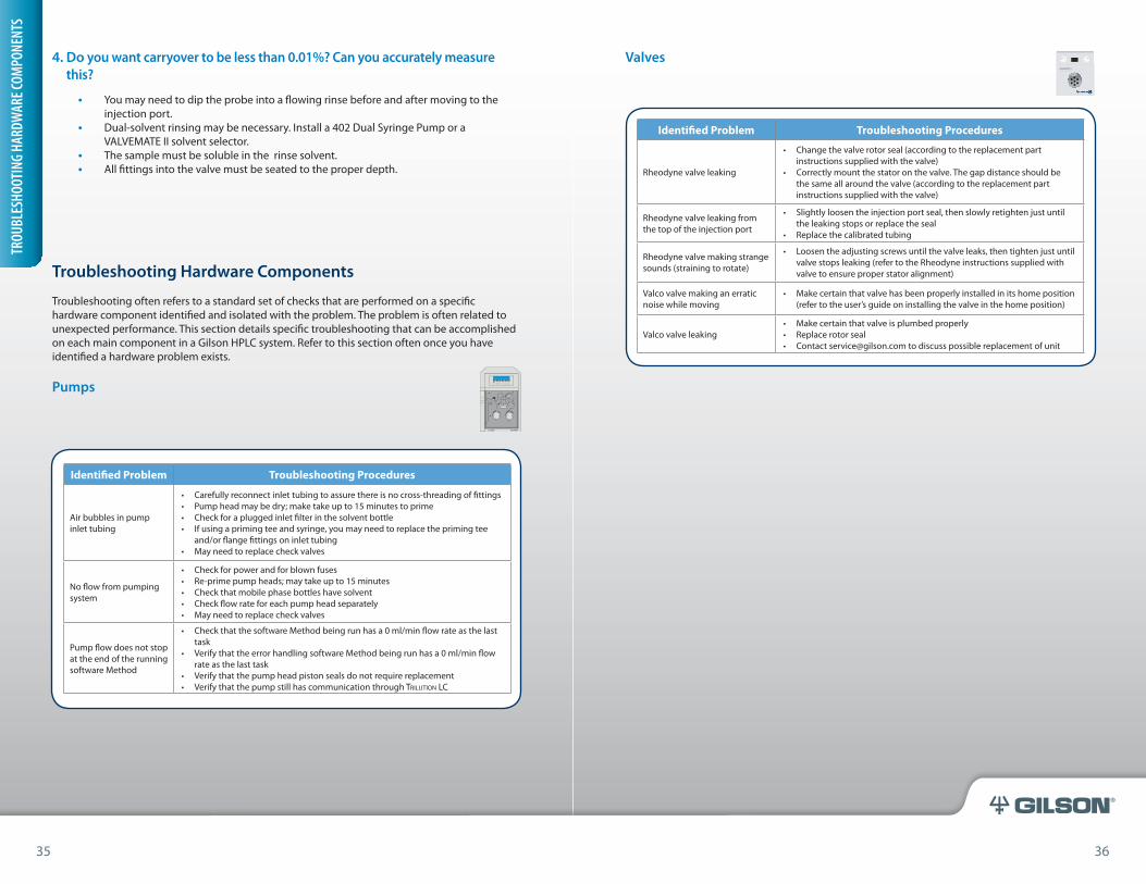
Pumps
Valves
Identified Problem Troubleshooting Procedures
Air bubbles in pump inlet tubing
• Carefully reconnect inlet tubing to assure there is no cross-threading of fittings• Pump head may be dry; make take up to 15 minutes to prime• Check for a plugged inlet filter in the solvent bottle• If using a priming tee and syringe, you may need to replace the priming tee
and/or flange fittings on inlet tubing• May need to replace check valves
No flow from pumping system
• Check for power and for blown fuses• Re-prime pump heads; may take up to 15 minutes• Check that mobile phase bottles have solvent• Check flow rate for each pump head separately• May need to replace check valves
Pump flow does not stop at the end of the running software Method
• Check that the software Method being run has a 0 ml/min flow rate as the last task
• Verify that the error handling software Method being run has a 0 ml/min flow rate as the last task
• Verify that the pump head piston seals do not require replacement• Verify that the pump still has communication through Trilution lC
Identified Problem Troubleshooting Procedures
Rheodyne valve leaking
• Change the valve rotor seal (according to the replacement part instructions supplied with the valve)
• Correctly mount the stator on the valve. The gap distance should be the same all around the valve (according to the replacement part instructions supplied with the valve)
Rheodyne valve leaking from the top of the injection port
• Slightly loosen the injection port seal, then slowly retighten just until the leaking stops or replace the seal
• Replace the calibrated tubing
Rheodyne valve making strange sounds (straining to rotate)
• Loosen the adjusting screws until the valve leaks, then tighten just until valve stops leaking (refer to the Rheodyne instructions supplied with valve to ensure proper stator alignment)
Valco valve making an erratic noise while moving
• Make certain that valve has been properly installed in its home position (refer to the user’s guide on installing the valve in the home position)
Valco valve leaking• Make certain that valve is plumbed properly• Replace rotor seal• Contact [email protected] to discuss possible replacement of unit
VALVEMATE® IIVALVE ACTUATOR
321 PUMP
35 36
TROU
BLES
HOOT
ING
HARD
WAR
E COM
PONE
NTS
38 39
®
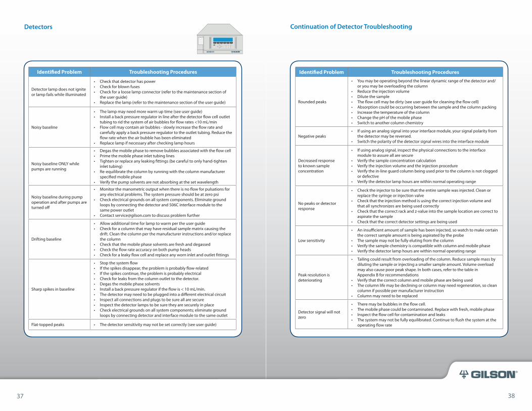
Identified Problem Troubleshooting Procedures
Detector lamp does not ignite or lamp fails while illuminated
• Check that detector has power• Check for blown fuses• Check for a loose lamp connector (refer to the maintenance section of
the user guide)• Replace the lamp (refer to the maintenance section of the user guide)
Noisy baseline
• The lamp may need more warm up time (see user guide)• Install a back pressure regulator in line after the detector flow cell outlet
tubing to rid the system of air bubbles for flow rates <10 mL/min• Flow cell may contain air bubbles - slowly increase the flow rate and
carefully apply a back pressure regulator to the outlet tubing. Reduce the flow rate when the air bubble has been eliminated
• Replace lamp if necessary after checking lamp hours
Noisy baseline ONLY while pumps are running
• Degas the mobile phase to remove bubbles associated with the flow cell• Prime the mobile phase inlet tubing lines• Tighten or replace any leaking fittings (be careful to only hand-tighten
inlet tubing)• Re-equilibrate the column by running with the column manufacturer
specified mobile phase• Verify the pump solvents are not absorbing at the set wavelength
Noisy baseline during pump operation and after pumps are turned off
• Monitor the manometric output when there is no flow for pulsations for any electrical problems. The system pressure should be at zero psi
• Check electrical grounds on all system components. Eliminate ground loops by connecting the detector and 506C interface module to the same power outlet
• Contact [email protected] to discuss problem further
Drifting baseline
• Allow additional time for lamp to warm per the user guide• Check for a column that may have residual sample matrix causing the
drift. Clean the column per the manufacturer instructions and/or replace the column
• Check that the mobile phase solvents are fresh and degassed• Check the flow rate accuracy on both pump heads• Check for a leaky flow cell and replace any worn inlet and outlet fittings
Sharp spikes in baseline
• Stop the system flow• If the spikes disappear, the problem is probably flow-related• If the spikes continue, the problem is probably electrical• Check for leaks from the column outlet to the detector.• Degas the mobile phase solvents• Install a back pressure regulator if the flow is < 10 mL/min.• The detector may need to be plugged into a different electrical circuit• Inspect all connections and plugs to be sure all are secure• Inspect the detector lamps to be sure they are securely in place• Check electrical grounds on all system components; eliminate ground
loops by connecting detector and interface module to the same outlet
Flat-topped peaks • The detector sensitivity may not be set correctly (see user guide)
UV/VIS-151®
Detectors
Identified Problem Troubleshooting Procedures
Rounded peaks
• You may be operating beyond the linear dynamic range of the detector and/or you may be overloading the column
• Reduce the injection volume• Dilute the sample• The flow cell may be dirty (see user guide for cleaning the flow cell)• Absorption could be occurring between the sample and the column packing• Increase the temperature of the column• Change the pH of the mobile phase• Switch to another column chemistry
Negative peaks• If using an analog signal into your interface module, your signal polarity from
the detector may be reversed.• Switch the polarity of the detector signal wires into the interface module
Decreased response to known sample concentration
• If using analog signal, inspect the physical connections to the interface module to assure all are secure
• Verify the sample concentration calculation• Verify the injection volume and the injection procedure• Verify the in-line guard column being used prior to the column is not clogged
or defective• Verify the detector lamp hours are within normal operating range
No peaks or detector response
• Check the injector to be sure that the entire sample was injected. Clean or replace the syringe or injection valve
• Check that the injection method is using the correct injection volume and that all synchronizes are being used correctly
• Check that the correct rack and z-value into the sample location are correct to aspirate the sample
• Check that the correct detector settings are being used
Low sensitivity
• An insufficient amount of sample has been injected, so watch to make certain the correct sample amount is being aspirated by the probe
• The sample may not be fully eluting from the column• Verify the sample chemistry is compatible with column and mobile phase• Verify the detector lamp hours are within normal operating range
Peak resolution is deteriorating
• Tailing could result from overloading of the column. Reduce sample mass by diluting the sample or injecting a smaller sample amount. Volume overload may also cause poor peak shape. In both cases, refer to the table in Appendix B for recommendations
• Verify that the correct column and mobile phase are being used• The column life may be declining or column may need regeneration, so clean
column if possible per manufacturer instruction• Column may need to be replaced
Detector signal will not zero
• There may be bubbles in the flow cell. • The mobile phase could be contaminated. Replace with fresh, mobile phase• Inspect the flow cell for contamination and leaks• The system may not be fully equilibrated. Continue to flush the system at the
operating flow rate
Continuation of Detector Troubleshooting
37 38
40 41
®
Identified Problem Troubleshooting Procedures
GX Solvent System not aspirating and dispensing liquids
• Verify plumbing connections are correct and per the user guide, with the first port being connected to a waste bottle
• Verify liquid lines are primed with solvent and free of air
Leaking injection valve on liquid handler
• Stop the system flow• If any of the fittings are leaking, carefully tighten them just until the leak
stops, being careful not to over tighten. Start the flow, and if the leak continues, replace the entire fitting
• If the valve is leaking around its circumference, replace the rotor seal (refer to the user guide or the instructions supplied with the valve)
• If liquid is leaking around the probe during loading of the sample loop, the loop or the connection between the loop and the valve is plugged
• If calibrated tubing is being used between the injection port and the valve, clean this ‘elbow’ per the user guide
• If you are using a manual injection valve, clean or replace the injection loop and fittings
Rheodyne valve making strange sounds (straining to rotate)
• Loosen the adjusting screws until the valve leaks, then tighten just until the valve stops leaking (refer to the Rheodyne instructions supplied with valve to ensure proper stator alignment
215 Liquid Handler or XL Sampler Y-arm (horizontal) won’t move
• The arm bracket or locking screw is still in place. For an XL sampler, remove the locking screw from the right side of the sampler using a Phillips screwdriver. For a 215 remove the arm bracket from the horizontal arm by loosening the allen screws
• Observe the liquid handler and sampler for any interferences within the fluid path or tubing that is restricting or catching on the tubing
• Check for errors on 215• Check to make sure nothing is impeding movement (tubing)
Liquid coming out of overflow port on 402 dilutor valve
• There is a plug between the dilutor outlet and the injection valve. Isolate the location of the plug, and then:1. Clean the line from the dilutor to the probe to eliminate possible high
back pressure2. Replace or clean the probe to eliminate any blockage3. Clean the injection port or replace4. Clean the calibrated tubing or replace (if present)5. Clean the valve by switching back and forth from load to inject
positions every 30 seconds while the mobile phase is flowing6. Sonicate the dilutor valve ceramic parts and re-assemble the valve
z-arm vibrates rapidly • Contact Gilson Customer Service for support
z-arm continues to access incorrect bed positions and bends probes
• For GX-2XX Liquid Handlers, use the Offset Utility software supplied and instructions in the user guide to correctly offset the instrument with a new probe(s)
• For 215 Liquid Handlers, contact Gilson’s Customer Service Department for support
Automated Liquid Handlers/Injectors
Identified Problem Troubleshooting Procedures
Collector is inoperative and unresponsive
• Check that the collector is plugged in and powered on• Check for blown fuses
Collector makes a loud noise when powered on (FC203B, FC204)
• The stepper motor and microprocessors must establish a reference point (‘home’ position – left rear) each time the collector is powered on. It is normal for the collector to make a vibrating noise for a few seconds while the motors are homing. This noise should occur only after the collector is powered on or when power is restored after a power failure
Collector makes a loud noise when changing X or Y position during a run
• Check for an obstruction to the X or Y movement by turning power off and manually moving the drop head and horizontal arm. They should move the full range of their travel smoothly and easily
Drops are missing the collection tubes
• If the collector is running from a keypad, verify that each rack code matches the installed rack
• If the collector is running via prepFC™ Control Software or Trilution LC Software, verify that the bed layout has the proper tray and racks selected
• Inspect the positioning of the racks to be certain they are properly seated on the tray
• Check for a crimp in the inlet tubing from the detector. Replace any crimped or damaged tubing
• Check that the tubing from the 3-way valve or drop detector is not bent of pushed up above the foot. Replace bent tubing. Replace any tubing that is too short and does not fall ~2 mm below the foot
• The collector may be out of alignment (FC203B, FC204, prepFC™). Check the horizontal arm assembly by powering the collector off then on. Contact Gilson’s Customer Service Department if the unit is still out of alignment
• The collector may need to be offset using the offset utility software (GX-281, GX-271). Follow the instructions in the user guide
• The collector may be out of alignment (215). Contact Gilson’s Customer Service Department if the unit is still out of alignment after powering off then on
The drop detector is not counting drops or is counting erratically
• Check that the tubing in the drop detector is not bent and is properly gauged (refer to FC203B, FC204, prepFC fraction collector user guide)
• Verify flow from the pumps is accurate and mobile phase lines are free of air.• Ensure that the inlet tubing fitting is completely tightened (the tubing should
not move up and down as the drop detector moves)• The tubing in the drop detector may be too short or too long• The drop detector tubing may have particulates on the tip. Clean the drop
detector collar with a wetted cotton swab• The drop detector assembly may be defective; contact Gilson’s Customer
Service Department for assistance with replacement• Ensure that the tubing coming from the detector source is not protruding more
than 1 mm past the nut/ferrule. Tubing that protrudes too far into the 3-way valve can damage the valve’s ability to open and close
• Verify settings in keypad or control software to make certain the proper volume is set for collection into the tubes
Prep FC
Fraction Collectors
39 40
42 43
®
Identified Problem Troubleshooting Procedures
Collection problems in peak mode
• If the collector is being controlled by prepFC Control Software, verify the parameters are appropriate for the peak shape and peak height of the signal
• If the collector is being controlled by Trilution LC Software, use the Fraction Collection Simulation function in the Method to try different peak collection parameters (see Help menu for assistance). Verify the parameters are appropriate for the peak shape and peak height of the signal. Verify the proper data signal is being used to trigger collection (right-click on the data channel and make sure that primary channel is selected with a check mark)
• If the collector is operating in a stand-alone mode, check the peak parameters in the keypad:• When collecting peaks by slope, the peak height should be the mV height
of the smallest peak• When collecting by level, the peak level should be the mV value above
which to collect peaks• The peak width should be the average width of the peaks at half height
• Eliminate any leaks. Install a back pressure regulator in the system if the flow is < 10 mL/min
• Verify that the delay volume or delay time has been accurately calculated and is used for collection (for flows < 10mL/min)
Not recognizing peaks in peak mode
• Check that the detector input voltage is less than 100 mV full scale• Check that the peak parameters set in the software match the size and shape
of the peaks to be collected• Check the polarity of the detector signal connections into the collector or
into the 506C (if using analog signal) to make certain the connections are not reversed
• Confirm that the fraction collector analog input or 506C is correctly zeroed:1. Disconnect the analog signal wires from the detector input connection on
the barrier strip at the back of the collector or 506C2. Short the detector input by connecting a piece of wire between the
positive (+) and negative (-) connections3. If using the keypad, press EDIT 3 on the collector keypad to access the
Service Menu. Press the Next softkey until the collector display reads Detector A/D: xxxx uV. Watch the display for a few minutes to see that the analog input stays zeroed (the actual reading may be +/- 20 uV). Press the Zero softkey to zero the analog input if it does not read 0 uV. Press the Quit softkey to return to the main screen
4. If using the 506C and Trilution LC Software, access the Manual Control screen and send an Autozero task to the 506C. Verify the signal displays 0 mV
5. Disconnect the short from the detector input on the barrier strip and reconnect the signal wires from the detector
• Confirm that your Trilution LC Software Method is sending a contact closure pulse to autozero the data signal through the 506C output and not using the autozero task on the 506C (prevents future problems with incorrect zeroing on the 506C)
Continuation of Fraction Collector Troubleshooting Continuation of Fraction Collector Troubleshooting
Identified Problem Troubleshooting Procedures
3-way valve is not functioning or is functioning incorrectly
• Turn off power to the collector and check that the connection to the socket and/or barrier strip is secure and no wires are loose
• Check that the connector is fully installed• Ensure that the tubing coming from the detector source is not protruding
more than 1 mm past the nut/ferrule. Tubing that protrudes too far into the 3-way valve can damage the valve’s ability to open and close
• Verify the flows are appropriate for the type of valve being used on the collector (reference specifications in user guide)
• The 3-way valve may be defective; contact Gilson’s Customer Service Department
Contact closure input or output functions are not operating
• Ensure that the wiring connections into the terminal block connector or barrier strip are secure, and that the connector is completely seated into the back of the fraction collector
• Verify the correct contact closure inputs or outputs are being used on the barrier strip and that these match with either the keypad or control software program
• Check the connections to the device providing input or output contact closure to verify these are secure and the correct pins are used. Verify wires are not reversed
• To check the input contact closure, short the collector input. If this successfully trips the input, then check the output from the external device. If this does not trip the input, check the barrier strip connector, multipurpose Input/Output port, or contact Gilson’s Customer Service Department
• To check the input contact closure when using control software, verify that manual control can properly trigger the contact closure
• Check the polarity of the input connection. Inputs should be a contact closure or TTL level (logic 0 activates this on a FC203B or FC204)
• The output signals from the collector are contact closures. This must be compatible with the external device
41 42
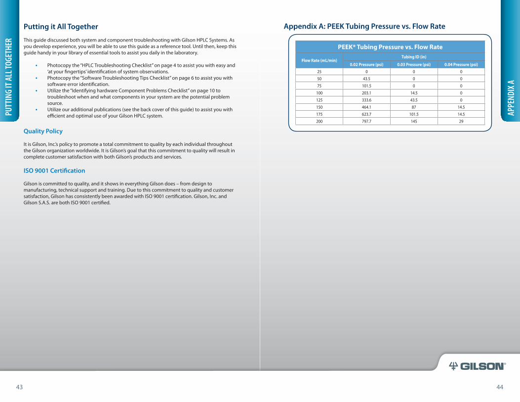
44 45
®
Putting it All Together This guide discussed both system and component troubleshooting with Gilson HPLC Systems. As you develop experience, you will be able to use this guide as a reference tool. Until then, keep this guide handy in your library of essential tools to assist you daily in the laboratory.
• Photocopy the “HPLC Troubleshooting Checklist” on page 4 to assist you with easy and ‘at your fingertips’ identification of system observations.
• Photocopy the “Software Troubleshooting Tips Checklist” on page 6 to assist you with software error identification.
• Utilize the “Identifying hardware Component Problems Checklist” on page 10 to troubleshoot when and what components in your system are the potential problem source.
• Utilize our additional publications (see the back cover of this guide) to assist you with efficient and optimal use of your Gilson HPLC system.
Quality Policy
It is Gilson, Inc.’s policy to promote a total commitment to quality by each individual throughout the Gilson organization worldwide. It is Gilson’s goal that this commitment to quality will result in complete customer satisfaction with both Gilson’s products and services.
ISO 9001 Certification
Gilson is committed to quality, and it shows in everything Gilson does – from design to manufacturing, technical support and training. Due to this commitment to quality and customer satisfaction, Gilson has consistently been awarded with ISO 9001 certification. Gilson, Inc. and Gilson S.A.S. are both ISO 9001 certified.
PUTT
ING
IT A
LL TO
GETH
ER
Appendix A: PEEK Tubing Pressure vs. Flow Rate
PEEK* Tubing Pressure vs. Flow Rate
Flow Rate (mL/min)Tubing ID (in)
0.02 Pressure (psi) 0.03 Pressure (psi) 0.04 Pressure (psi)25 0 0 0
50 43.5 0 0
75 101.5 0 0
100 203.1 14.5 0
125 333.6 43.5 0
150 464.1 87 14.5
175 623.7 101.5 14.5
200 797.7 145 29
APPE
NDIX
A
43 44
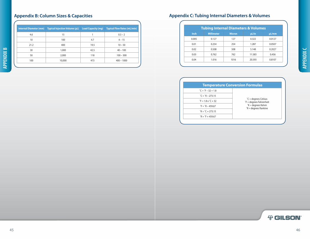
46 47
®
Appendix B: Column Sizes & Capacities
Internal Diameter (mm) Typical Injection Volume (µL) Load Capacity (mg) Typical Flow Rates (mL/min)
4.6 15 1 0.5 – 2
10 100 4.7 4 – 15
21.2 400 19.5 10 – 50
30 1,000 42.5 40 – 100
50 2,000 118 100 – 300
100 10,000 473 400 – 1000
APPE
NDIX
B
Appendix C: Tubing Internal Diameters & Volumes
Temperature Conversion Formulas˚C = ˚F – 32 ÷ 1.8
˚C = degrees Celsius˚F = degrees Fahrenheit
˚K = degrees Kelvin˚R = degrees Rankine
˚C = ˚K – 273.15
˚F = 1.8 x ˚C + 32
˚F = ˚R – 459.67
˚K = ˚C + 273.15
˚R = ˚F + 459.67
Tubing Internal Diameters & Volumes Inch Millimeter Micron µL/in µL/mm
0.005 0.127 127 0.322 0.0127
0.01 0.254 254 1.287 0.0507
0.02 0.508 508 5.148 0.2027
0.03 0.762 762 11.583 0.456
0.04 1.016 1016 20.593 0.8107
APPE
NDIX
C
45 46
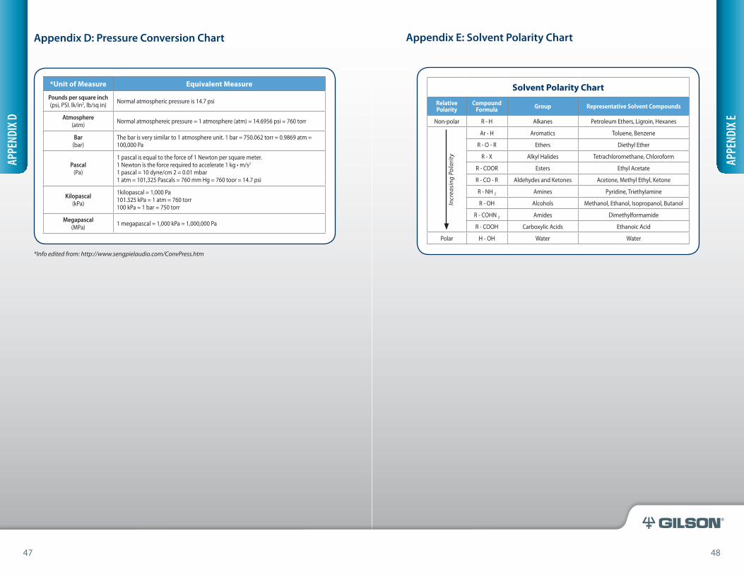
48 49
®
Appendix D: Pressure Conversion Chart
*Info edited from: http://www.sengpielaudio.com/ConvPress.htm
*Unit of Measure Equivalent Measure
Pounds per square inch(psi, PSI. lk/in2, lb/sq in) Normal atmospheric pressure is 14.7 psi
Atmosphere(atm) Normal atmosphereic pressure = 1 atmosphere (atm) = 14.6956 psi = 760 torr
Bar(bar)
The bar is very similar to 1 atmosphere unit. 1 bar = 750.062 torr = 0.9869 atm = 100,000 Pa
Pascal(Pa)
1 pascal is equal to the force of 1 Newton per square meter.1 Newton is the force required to accelerate 1 kg • m/s2
1 pascal = 10 dyne/cm 2 = 0.01 mbar1 atm = 101,325 Pascals = 760 mm Hg = 760 toor = 14.7 psi
Kilopascal(kPa)
1kilopascal = 1,000 Pa101.325 kPa = 1 atm = 760 torr100 kPa = 1 bar = 750 torr
Megapascal(MPa) 1 megapascal = 1,000 kPa = 1,000,000 Pa
APPE
NDIX
D
Appendix E: Solvent Polarity Chart
Solvent Polarity Chart
Relative Polarity
Compound Formula Group Representative Solvent Compounds
Non-polar R - H Alkanes Petroleum Ethers, Ligroin, Hexanes
Incr
easi
ng P
olar
ity
Ar - H Aromatics Toluene, Benzene
R - O - R Ethers Diethyl Ether
R - X Alkyl Halides Tetrachloromethane, Chloroform
R - COOR Esters Ethyl Acetate
R - CO - R Aldehydes and Ketones Acetone, Methyl Ethyl, Ketone
R - NH 2 Amines Pyridine, Triethylamine
R - OH Alcohols Methanol, Ethanol, Isopropanol, Butanol
R - COHN 2 Amides Dimethylformamide
R - COOH Carboxylic Acids Ethanoic Acid
Polar H - OH Water Water
APPE
NDIX
E
47 48
TRILUTION
LC v2.1–Vol 1
TriluTion® LC Software v2.1 Technical Notes Handbook
Price – $25.00
US $45
Contact your local Gilson representative or contact [email protected] to obtain our quarterly Gilson Application Notes Handbook and our series of Trilution® LC Technical Notes Handbooks.
Additional Publications from Gilson
Quarterly Gilson Application Notes Handbook
Trilution® LC Technical Notes Handbook Series
Application Notes HandbookPipettes | Purification | Solid Phase Extraction
2011–Volume 1
Gilson, Inc. World Headquarters | PO Box 620027 | MIddleton, WI 53562-0027, USA | Tel: 800-445-7661 | Fax: 608-831-4451Gilson S.A.S. | 19, avenue des Entrepreneurs | BP 145 | F-95400 Villiers-le-bel, FRANCEwww.gilson.com | [email protected] | [email protected] | [email protected] | LT318017-04 | © 2011 Gilson, Inc. | GKCHPLCGUIDE