Embed Size (px)
Citation preview
HPE Synergy 12Gb SAS Storage UserGuide
Part Number: 789815-002Published: October 2017Edition: 2
AbstractThis document is for the person who installs, administers, and troubleshoots the HPE Synergy12Gb SAS Connection Module, HPE Synergy D3940 Storage Module, HPE Smart ArrayP542D RAID Controller, and HPE Smart Array P416ie-m SR Gen10 Controller for the HPESynergy 12000 Frame. Hewlett Packard Enterprise assumes you are qualified in the servicingof computer equipment and trained in recognizing hazards in products with hazardous energylevels.

© Copyright 2016, 2017 Hewlett Packard Enterprise Development LP
NoticesThe information contained herein is subject to change without notice. The only warranties for HewlettPackard Enterprise products and services are set forth in the express warranty statements accompanyingsuch products and services. Nothing herein should be construed as constituting an additional warranty.Hewlett Packard Enterprise shall not be liable for technical or editorial errors or omissions containedherein.
Confidential computer software. Valid license from Hewlett Packard Enterprise required for possession,use, or copying. Consistent with FAR 12.211 and 12.212, Commercial Computer Software, ComputerSoftware Documentation, and Technical Data for Commercial Items are licensed to the U.S. Governmentunder vendor's standard commercial license.
Links to third-party websites take you outside the Hewlett Packard Enterprise website. Hewlett PackardEnterprise has no control over and is not responsible for information outside the Hewlett PackardEnterprise website.
Contents
Product overview.................................................................................... 6Synergy SAS Storage features..................................................................................................... 6HPE Synergy 12Gb SAS Connection Module.............................................................................. 6
Features............................................................................................................................. 6Front panel and LED definitions.........................................................................................7
HPE Synergy D3940 Storage Module.......................................................................................... 7Features............................................................................................................................. 7Front panel components.................................................................................................... 8Front panel and LED definitions.........................................................................................8Side panel.......................................................................................................................... 9Device bay numbering..................................................................................................... 10SmartDrive hot-plug drive LED definitions........................................................................11VRM................................................................................................................................. 12
HPE Smart Array controllers.......................................................................................................13HPE Smart Array P542D RAID Controller........................................................................13HPE Smart Array P416ie-m Controller.............................................................................15
Planning................................................................................................. 18Performance................................................................................................................................18Wiring diagram............................................................................................................................18Synergy D3940 drive count and performance details................................................................. 20Synergy SAS storage solution planning guidelines.................................................................... 21Server profile...............................................................................................................................21
Local storage configuration options................................................................................. 21Server profile mobility.......................................................................................................22Logical JBOD drive selection........................................................................................... 22
Deployment............................................................................................23Installing Synergy SAS storage solution components................................................................ 23
12Gb SAS Connection Module installation guidelines..................................................... 23D3940 Storage Module installation guidelines................................................................. 24Installing drives.................................................................................................................26HPE Smart Array controller installation guidelines...........................................................27
Configuration...............................................................................................................................28Firmware bundle...............................................................................................................29Logical interconnect groups............................................................................................. 30Enclosure group............................................................................................................... 32Logical enclosure............................................................................................................. 35Check alerts..................................................................................................................... 36Server profiles.................................................................................................................. 40
Inventory..................................................................................................................................... 46Interconnect......................................................................................................................46Drive enclosure................................................................................................................ 46
Operations............................................................................................. 48Status event notifications............................................................................................................ 48
Contents 3
Receiving event notifications through HPE OneView GUI............................................... 48Receiving event notifications through HPE OneView RESTapi........................................49
Firmware..................................................................................................................................... 50Updating the firmware...................................................................................................... 50
Modifying local storage............................................................................................................... 50Expanding local storage...................................................................................................50Editing server profile.........................................................................................................51
Replacing Synergy SAS storage solution components...............................................................51Replacing 12Gb SAS Connection Module....................................................................... 51Replacing Synergy D3940 Storage Module Enclosure.................................................... 53Replacing D3940 I/O adapter...........................................................................................54
Electrostatic discharge.........................................................................56Preventing electrostatic discharge.............................................................................................. 56Grounding methods to prevent electrostatic discharge...............................................................56
Specifications........................................................................................57Environmental specifications...................................................................................................... 5712Gb SAS Connection Module specifications............................................................................ 57D3940 Storage Module specifications........................................................................................ 58P542D specifications.................................................................................................................. 58P416ie-m specifications.............................................................................................................. 59
Documentation and troubleshooting resources for HPE Synergy...61Documentation and troubleshooting resources for HPE Synergy...............................................61
HPE Synergy documentation........................................................................................... 61HPE Synergy troubleshooting resources......................................................................... 63
HPE Synergy document overview (documentation map)........................................................... 63
Acronyms and abbreviations...............................................................65
Support and other resources...............................................................67Accessing Hewlett Packard Enterprise Support......................................................................... 67Accessing updates......................................................................................................................67Customer self repair....................................................................................................................68Remote support.......................................................................................................................... 68Warranty information...................................................................................................................68Regulatory information................................................................................................................69Documentation feedback............................................................................................................ 69
4 Contents

AcknowledgmentsMicrosoft® and Windows® are either registered trademarks or trademarks of Microsoft Corporation in theUnited States and/or other countries.
Java™ is a US trademark of Sun Microsystems, Inc.
UNIX® is a registered trademark of The Open Group.
Acknowledgments 5
Product overviewSynergy SAS Storage features
Synergy SAS Storage supports the following types of devices that are designed for use in an HPESynergy 12000 Frame:
• HPE Synergy 12Gb SAS Connection Module
• HPE Synergy D3940 Storage Module
• HPE Smart Array P542D RAID Controller
• HPE Smart Array P416ie-m RAID Controller
HPE Synergy D3940 Storage Module is a 40 SFF drive bay module, and the HPE Synergy 12Gb SASConnection Module is a connection module that allows direct attached storage for up to 10 computemodules per frame.
Synergy SAS storage is optimized for use as either a direct attached storage array or as software-definedstorage using HPE StoreVirtual VSA or similar solutions.
Storage modules connect to compute modules within a frame through the HPE Synergy 12Gb SASConnection Module. Any number of drive bays in a storage module can be composed with any computemodule for efficient use of available drives. Synergy SAS storage can scale up to 200 SFF drives with fivestorage modules in a single HPE Synergy 12000 Frame. Adding a second I/O adapter and second SASconnection module provides a redundant path to SAS drives inside the storage module, ensuring highavailability.
HPE Synergy 12Gb SAS Connection ModuleThe following components are located in the HPE Synergy 12Gb SAS Connection Module.
Features
• Hot Pluggable connection module for HPE Synergy 12000 Frame
• Dual Domain direct attached SAS architecture supported with HPE Synergy D3940 Storage Modulescontaining two I/O adapters
• 12 internal blade bay ports each containing 4x 12Gb/s SAS links
• Managed with HPE Synergy Composer and HPE OneView version 3.0 or higher
6 Product overview
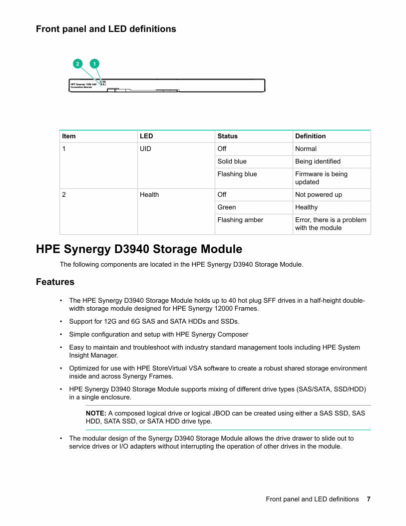
Front panel and LED definitions
Item LED Status Definition
1 UID Off Normal
Solid blue Being identified
Flashing blue Firmware is beingupdated
2 Health Off Not powered up
Green Healthy
Flashing amber Error, there is a problemwith the module
HPE Synergy D3940 Storage ModuleThe following components are located in the HPE Synergy D3940 Storage Module.
Features
• The HPE Synergy D3940 Storage Module holds up to 40 hot plug SFF drives in a half-height double-width storage module designed for HPE Synergy 12000 Frames.
• Support for 12G and 6G SAS and SATA HDDs and SSDs.
• Simple configuration and setup with HPE Synergy Composer
• Easy to maintain and troubleshoot with industry standard management tools including HPE SystemInsight Manager.
• Optimized for use with HPE StoreVirtual VSA software to create a robust shared storage environmentinside and across Synergy Frames.
• HPE Synergy D3940 Storage Module supports mixing of different drive types (SAS/SATA, SSD/HDD)in a single enclosure.
NOTE: A composed logical drive or logical JBOD can be created using either a SAS SSD, SASHDD, SATA SSD, or SATA HDD drive type.
• The modular design of the Synergy D3940 Storage Module allows the drive drawer to slide out toservice drives or I/O adapters without interrupting the operation of other drives in the module.
Front panel and LED definitions 7
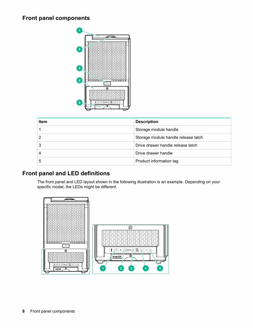
Front panel components
Item Description
1 Storage module handle
2 Storage module handle release latch
3 Drive drawer handle release latch
4 Drive drawer handle
5 Product information tag
Front panel and LED definitionsThe front panel and LED layout shown in the following illustration is an example. Depending on yourspecific model, the LEDs might be different.
8 Front panel components
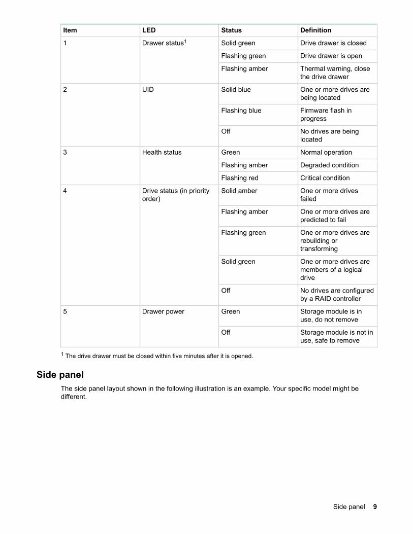
Item LED Status Definition
1 Drawer status1 Solid green Drive drawer is closed
Flashing green Drive drawer is open
Flashing amber Thermal warning, closethe drive drawer
2 UID Solid blue One or more drives arebeing located
Flashing blue Firmware flash inprogress
Off No drives are beinglocated
3 Health status Green Normal operation
Flashing amber Degraded condition
Flashing red Critical condition
4 Drive status (in priorityorder)
Solid amber One or more drivesfailed
Flashing amber One or more drives arepredicted to fail
Flashing green One or more drives arerebuilding ortransforming
Solid green One or more drives aremembers of a logicaldrive
Off No drives are configuredby a RAID controller
5 Drawer power Green Storage module is inuse, do not remove
Off Storage module is not inuse, safe to remove
1 The drive drawer must be closed within five minutes after it is opened.
Side panelThe side panel layout shown in the following illustration is an example. Your specific model might bedifferent.
Side panel 9
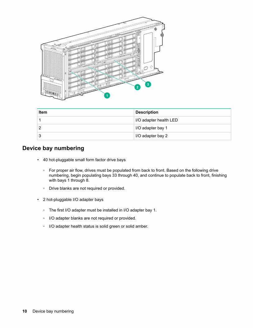
Item Description
1 I/O adapter health LED
2 I/O adapter bay 1
3 I/O adapter bay 2
Device bay numbering
• 40 hot-pluggable small form factor drive bays
◦ For proper air flow, drives must be populated from back to front. Based on the following drivenumbering, begin populating bays 33 through 40, and continue to populate back to front, finishingwith bays 1 through 8.
◦ Drive blanks are not required or provided.
• 2 hot-pluggable I/O adapter bays
◦ The first I/O adapter must be installed in I/O adapter bay 1.
◦ I/O adapter blanks are not required or provided.
◦ I/O adapter health status is solid green or solid amber.
10 Device bay numbering
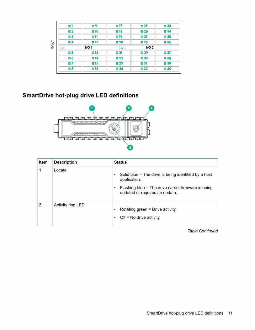
SmartDrive hot-plug drive LED definitions
Item Description Status
1 Locate• Solid blue = The drive is being identified by a host
application.
• Flashing blue = The drive carrier firmware is beingupdated or requires an update.
2 Activity ring LED• Rotating green = Drive activity.
• Off = No drive activity.
Table Continued
SmartDrive hot-plug drive LED definitions 11
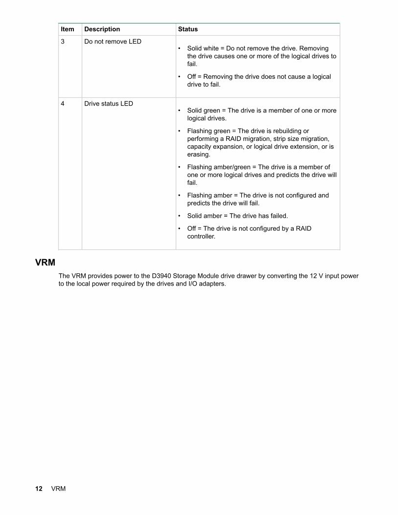
Item Description Status
3 Do not remove LED• Solid white = Do not remove the drive. Removing
the drive causes one or more of the logical drives tofail.
• Off = Removing the drive does not cause a logicaldrive to fail.
4 Drive status LED• Solid green = The drive is a member of one or more
logical drives.
• Flashing green = The drive is rebuilding orperforming a RAID migration, strip size migration,capacity expansion, or logical drive extension, or iserasing.
• Flashing amber/green = The drive is a member ofone or more logical drives and predicts the drive willfail.
• Flashing amber = The drive is not configured andpredicts the drive will fail.
• Solid amber = The drive has failed.
• Off = The drive is not configured by a RAIDcontroller.
VRMThe VRM provides power to the D3940 Storage Module drive drawer by converting the 12 V input powerto the local power required by the drives and I/O adapters.
12 VRM
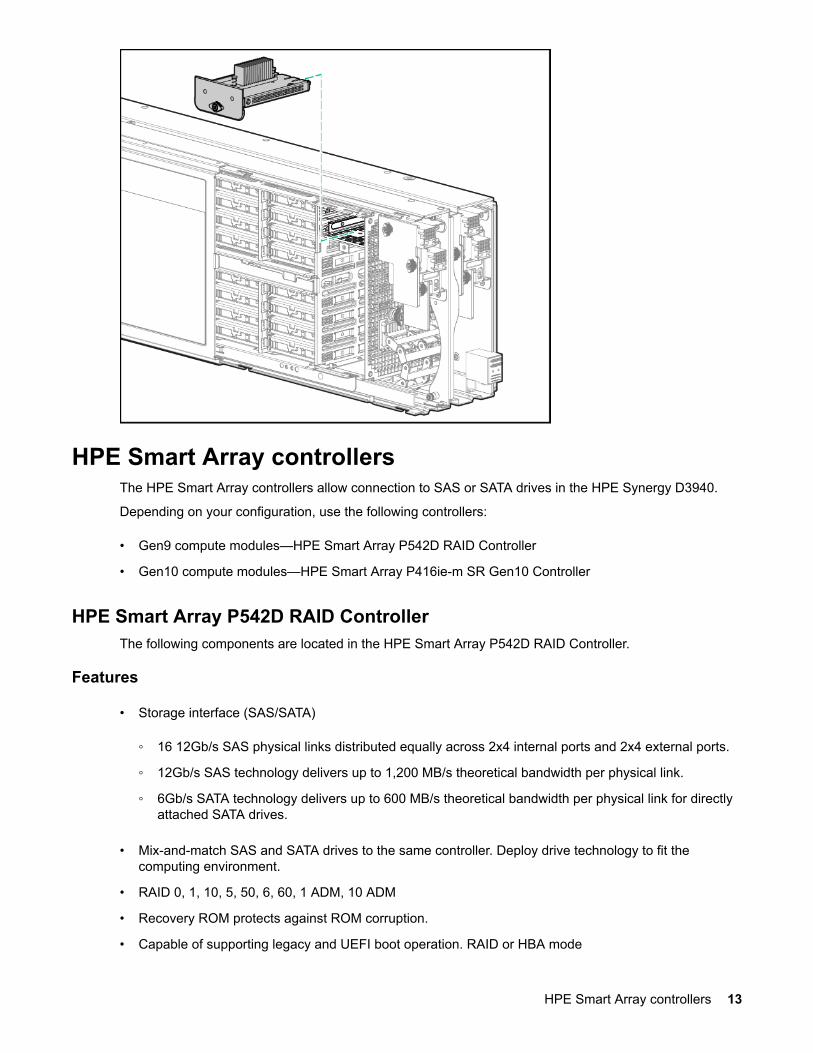
HPE Smart Array controllersThe HPE Smart Array controllers allow connection to SAS or SATA drives in the HPE Synergy D3940.
Depending on your configuration, use the following controllers:
• Gen9 compute modules—HPE Smart Array P542D RAID Controller
• Gen10 compute modules—HPE Smart Array P416ie-m SR Gen10 Controller
HPE Smart Array P542D RAID ControllerThe following components are located in the HPE Smart Array P542D RAID Controller.
Features
• Storage interface (SAS/SATA)
◦ 16 12Gb/s SAS physical links distributed equally across 2x4 internal ports and 2x4 external ports.
◦ 12Gb/s SAS technology delivers up to 1,200 MB/s theoretical bandwidth per physical link.
◦ 6Gb/s SATA technology delivers up to 600 MB/s theoretical bandwidth per physical link for directlyattached SATA drives.
• Mix-and-match SAS and SATA drives to the same controller. Deploy drive technology to fit thecomputing environment.
• RAID 0, 1, 10, 5, 50, 6, 60, 1 ADM, 10 ADM
• Recovery ROM protects against ROM corruption.
• Capable of supporting legacy and UEFI boot operation. RAID or HBA mode
HPE Smart Array controllers 13
• HPE SSD Smart Path
• Optional HPE SmartCache
• Optional HPE Secure Encryption
• PCIe Gen3 x8 link
• If there is an unexpected power outage, 2GB FBWC provides read ahead caching and write backcaching with indefinite write cache data retention.
• The following features require the controller to be manually managed
◦ RAID 50 and 60
◦ Smart cache (requires license).
◦ FBWC (other than default setting)
◦ Stripe Size (other than default setting)
◦ Spare drive
◦ Spare activation modes
◦ Multiple logical drives in a single array
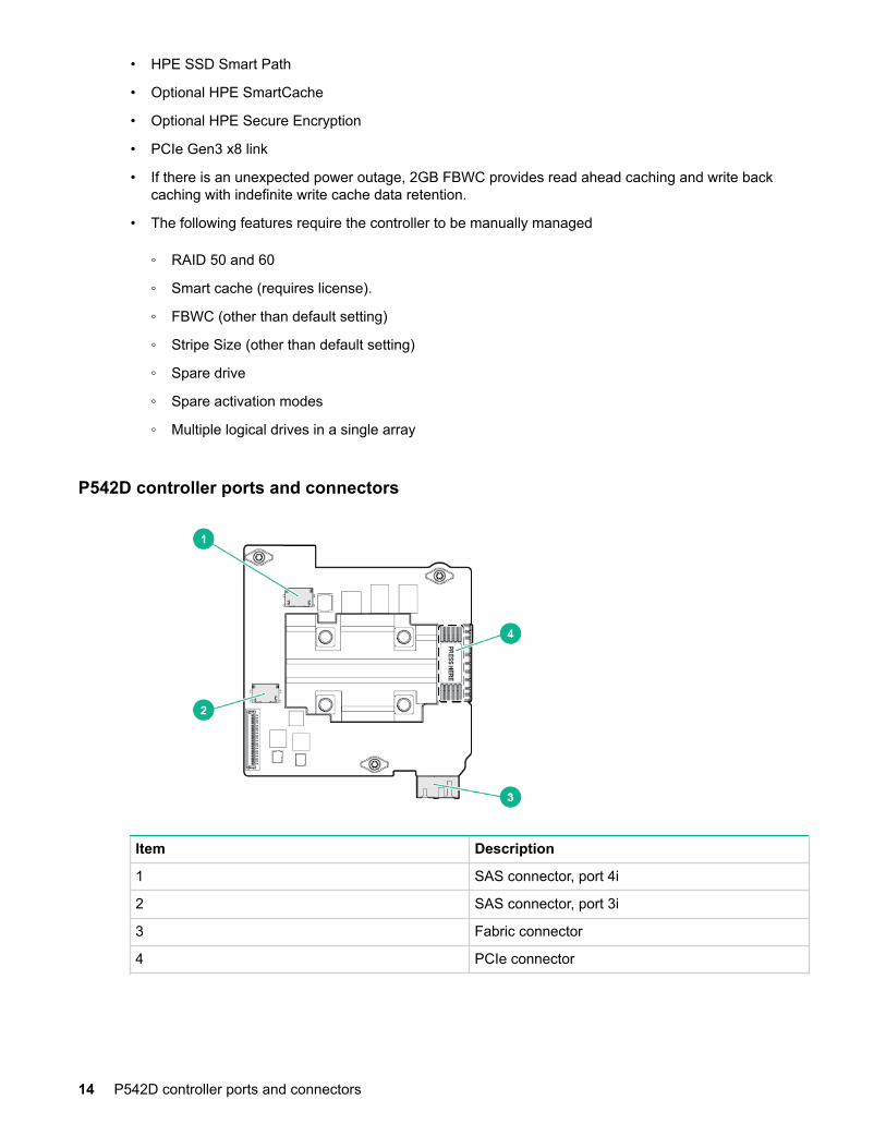
P542D controller ports and connectors
Item Description
1 SAS connector, port 4i
2 SAS connector, port 3i
3 Fabric connector
4 PCIe connector
14 P542D controller ports and connectors
HPE Smart Array P416ie-m ControllerThe following components are located in the HPE Smart Array P416ie-m Controller.
Features
• Up to 16 SAS/SATA lanes for internal or external drives
• RAID levels 0, 1, 5, 6, 10, 50, 60, 1 ADM, and 10 ADM
• Mixed mode RAID and HBA pass-through functionality simultaneously
• Data-at-rest encryption
• 12G SAS support
• UEFI and Legacy Boot modes
• Best RAID performance capabilities with large flash-backed write cache
• Smart Array management tools
Security
IMPORTANT:
All the features described in this section only apply to the HPE Smart Array P416ie-m Controller.
HPE Smart Array SR Secure EncryptionHPE Smart Array SR Secure Encryption is a controller-based, enterprise-class data encryption solutionthat protects data at rest on any SAS/SATA drive attached to the HPE Smart Array controller. The solutionis available for both local and remote deployments.
HPE Smart Array SR Secure Encryption is configured using the HPE Smart Storage Administrator (SSA).
Prerequisites:
• An installed Smart Array Controller compatible with Secure Encryption
• A valid Secure Encryption license for each server to be encrypted.
Local Key Management ModeLocal Key Management Mode, or Local Mode, is a solution designed for small to medium-size datacenters. The solution utilizes a paraphrase password, or Master Encryption Key name, to set the securityon the controller and enable encryption. The Master Encryption Key must be tracked independently of thecontrollers in case the controller needs replacement or drive migration is required among controllers withdifferent passwords. For more information, see HPE Smart Array SR Secure Encryption Installation andUser Guide.
This method has the following benefits:
• Encrypts data on both the attached bulk storage and the cache memory of Smart Array Controllers.
• Supports any HDD or SSD in the HPE server portfolio.
• Does not require ESKM.
HPE Smart Array P416ie-m Controller 15
Remote Key Management ModeIn Remote Key Management Mode, keys are imported and exported between the controller and theEnterprise Secure Key Manager (ESKM), which provides a redundant, secure store with continuousaccess to the keys. To enable key exchanges between the Smart Array Controller and the ESKM, anetwork connection is required both during pre-OS boot time and during OS operations. Because thecontroller does not have direct network access capabilities, iLO provides the necessary network access tofacilitate key exchanges between the controller and the ESKM. For more information see, HPE SmartArray SR Secure Encryption Installation and User Guide.
Prerequisites:
• Integrated Lights Out (iLO) Advanced or Scale Out Edition license, per ProLiant server
• Network availability
• Remote ESKM
This method has the following benefits:
• Encrypts data on both the attached bulk storage and the cache memory of Smart Array Controllers
• Supports any HDD or SSD in the HPE server portfolio
• Keys are kept in separate storage from servers to protect against physical removal
Sanitize eraseWhen you sanitize erase a drive, you remove all sensitive information from a physical drive. This includesnon-volatile media, non-volatile cache, bad blocks, and overprovisioned areas. Sanitize erase operationscannot be stopped after starting, and the drive will continue to sanitize after a hot-plug or server reboot.During the sanitize erase operation, the drive is unusable until after the process is complete. After theerase completes, the drive will be kept offline to prevent access until re-enabled.
Sanitize erase methods
• Restricted - Using the restricted sanitize method means that until a drive successfully completes thesanitize operation, it will be unusable. If a restricted sanitize operation fails, you are only allowed tostart another sanitize operation, or, if the drive is under warranty, you can return it to HPE.
• Unrestricted - Using the unrestricted sanitize method means that the drive will be recoverable in thecase that the sanitize erase operation fails. User data may still be present on the drive. Not all drivessupport unrestricted.
Sanitize overwrite (HDD)Sanitize overwrite fills every physical sector of the drive with a pattern.
This method has the following benefits:
• Removes all sensitive information from the drive
• Once started, the drive will continue to sanitize regardless of resets and power cycles
Sanitize block erase (SSD)Sanitize block erase sets the blocks on the drive to a vendor-specific value, removing all user data.
This method has the following benefits:
16 Product overview
• Removes all sensitive information from the drive
• Once started, the drive continues to sanitize regardless of resets and power cycles
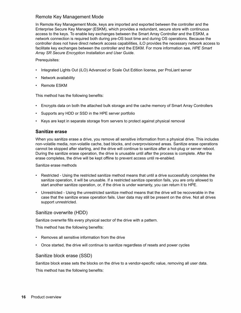
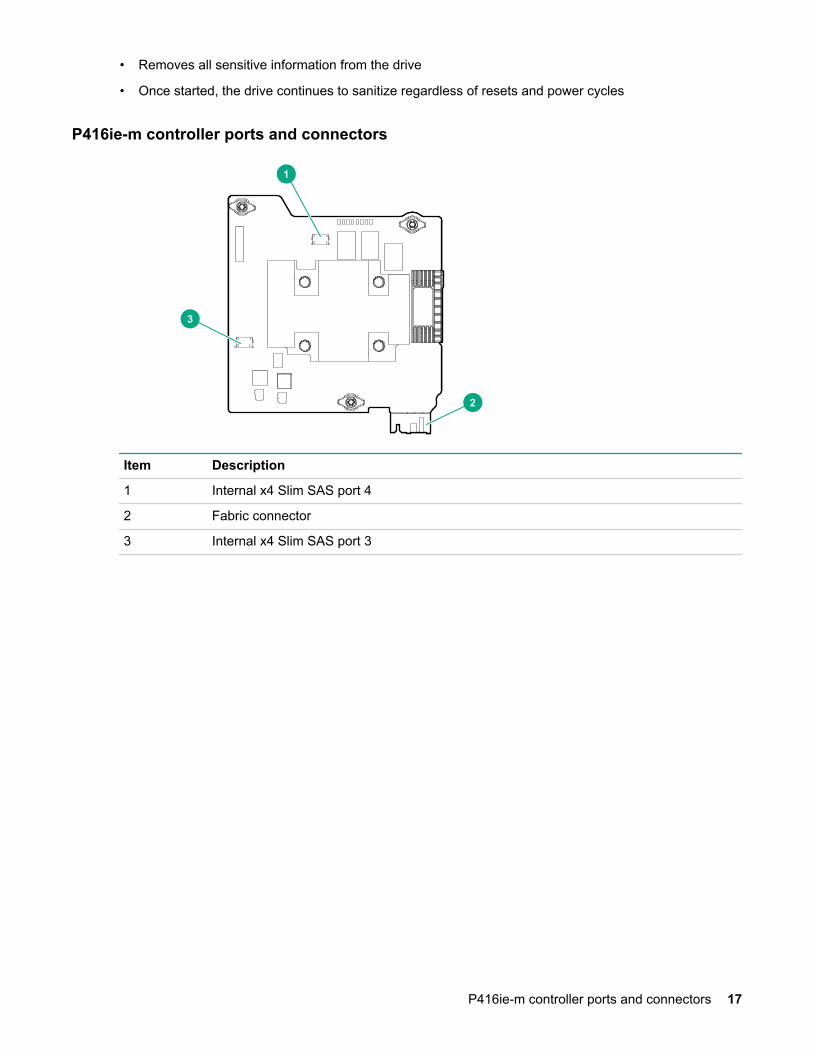
P416ie-m controller ports and connectors
2
3
1
Item Description
1 Internal x4 Slim SAS port 4
2 Fabric connector
3 Internal x4 Slim SAS port 3
P416ie-m controller ports and connectors 17
PlanningPerformance
Measuring I/O performance is done from the host operating system. Some tools that measure I/Operformance include the following:
• Windows—PerfMon
• Linux—sar command from systat.
• VMware—vSphere Client disk
Wiring diagramBefore planning a frame level layout for your storage and compute modules, it is helpful to understandsome basic principles of how the frame is designed and how the connections are made between computeand storage modules. D3940 Storage Module may be connected to any HPE Smart Array Controller-equipped compute module that is installed in the same frame with the following configuration options:
• Redundant pairs of HPE Synergy 12Gb SAS Connection Module
• Nonredundant single HPE Synergy 12Gb SAS Connection Module
As a best practice, Hewlett Packard Enterprise recommends designing your storage fabric for fullredundancy; however, nonredundant solutions are supported with the correct configuration. In thefollowing figure, you will see how the fabric allows for connections to single or dual I/O adapters in eachstorage module, as well as routing required in nonredundant connections.
When configured for redundancy two connection modules are configured in the frame residing in ICMbays 1 and 4, and each storage module contains a pair of I/O adapters. This redundancy provides dualpaths for each HPE Smart Array controller to be able to connect with any storage module in the frameregardless of where in the frame the storage module is configured. However, when there areconfigurations where there is either only a single connection module present or the connection modulesand storage modules are configured nonredundant, make sure that the storage modules are aligned inthe correct module bays to be serviced by the correct connection modules.
A SAS Connection module in ICM bay 1 will provide connection from the primary I/O adapter to anystorage module in device bays 1-6. For device bays 7-12, ICM bay 1 is routed to the secondary(redundant) I/O adapter. In a nonredundant storage fabric configuration, the secondary connection wouldnot be active. Likewise, a SAS connection module ICM bay 4 will offer to connect to the primary I/Oadapter of a storage module any place in device bays 7-12, but will not access the primary I/O adapter inBays 1-6. If redundancy is not configured if the SAS fabric, it is required that connection modules in ICM 1will only support storage modules in device bays 1-6 and connection modules in ICM 4 will only supportstorage modules in device bays 7-12, but will not access the primary I/O adapter in Bays 1-6. Ifredundancy is not configured if the SAS fabric, it is required that connection modules in ICM 1 will onlysupport storage modules in device bays 1-6 and connection modules in ICM 4 will only support storagemodules in device bays 7-12.
This routing does not impede compute module access to a storage module regardless of where thestorage module is located. For example, a compute module in device bay 1 will connect to a storagemodule in device bay 11, even in a nonredundant configuration, as long as the connection module iscorrectly placed in ICM 4 to align with the location of the storage module.
18 Planning
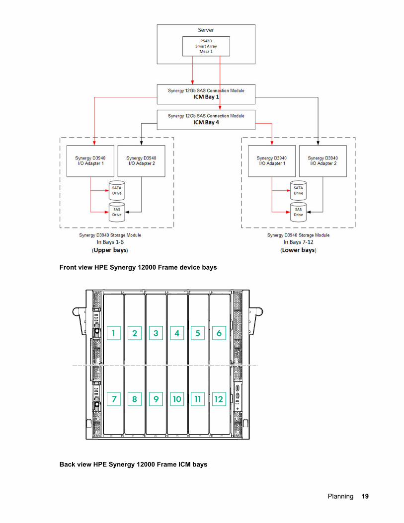
Front view HPE Synergy 12000 Frame device bays
Back view HPE Synergy 12000 Frame ICM bays
Planning 19
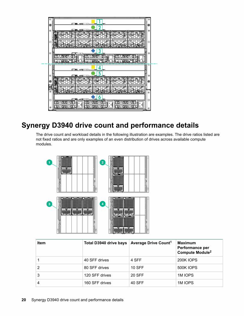
Synergy D3940 drive count and performance detailsThe drive count and workload details in the following illustration are examples. The drive ratios listed arenot fixed ratios and are only examples of an even distribution of drives across available computemodules.
Item Total D3940 drive bays Average Drive Count1 MaximumPerformance perCompute Module2
1 40 SFF drives 4 SFF 200K IOPS
2 80 SFF drives 10 SFF 500K IOPS
3 120 SFF drives 20 SFF 1M IOPS
4 160 SFF drives 40 SFF 1M IOPS
20 Synergy D3940 drive count and performance details
1 Based on full Synergy Frame.2 Assumes that 12G SAS SSD drives are running 4 KB random read workload using a redundant configuration.
Synergy SAS storage solution planning guidelinesWhen planning the installation of components in a frame, the following guidelines must be observed.
• Select up to three D3940 Storage Modules per frame when installing a single HPE Synergy 12Gb SASConnection Module.
• Select up to five D3940 Storage Modules per frame when installing dual HPE Synergy 12Gb SASConnection Modules.
• One SAS I/O adapter is included with every D3940 Storage Module.
• For redundancy and higher performance when using SAS drives, a second I/O adapter andconnection module must be added.
• Any compute module connecting to a D3940 Storage Module must have an HPE Smart ArrayController populated in fabric 1, which is mezzanine slot 1 or 4.
• If the D3940 Storage Module is configured with two SAS I/O adapters, a second SAS connectionmodule is required.
• Each Synergy frame that contains at least one HPE Synergy D3940 Storage Module must also containat least one connection module.
• There can be no more than two HPE Synergy 12Gb SAS Connection Modules in each frame.
• The HPE Smart Array controllers require a Smart Storage battery (HPE 96W Smart Storage Batterywith 260mm Cable 782958-B21).
• The Smart Storage battery that is included with the P240nr can be shared with a controller. If there isno P240nr installed in the frame, a Smart Storage battery kit must be ordered.
• If a premium backplane is used, the P542D Controller that is cabled to the premium backplane mustbe installed in mezzanine slot 1.
• One SAS cable option kit (815173-B21) is required for each premium backplane the P542D Controlleruses in a compute module.
• One SR Gen 10 SAS cable option kit (871573-B21) is required for each premium backplan theP416ie-m controller uses in a compute module.
Server profileA server profile is a set of configuration settings and resources that are allocated to a compute modulewithin the Synergy frame.
Local storage configuration optionsCreating a server profile requires the following information:
• Controller mode (RAID or HBA)—The Smart Array Controller can operate as a RAID controller or anHBA. The controller cannot operate in both modes simultaneously.
• Drive count—The number of drives required to create the logical JBOD and logical drive.
• Drive technology—Used to filter the drives located in the D3940 Storage Module to select betweenSAS HDD, SATA HDD, SAS SSD, or SATA SSD.
Synergy SAS storage solution planning guidelines 21
• Minimum and maximum drive capacity—Used to filter the drives located in the D3940 StorageModule to select drives specified by the minimum and maximum drive capacity.
• RAID level (optional)—Used to specify the RAID level of the logical drive. This field does not appearwhen the controller is in HBA mode or when creating logical JBODs.
Server profile mobilityA server profile can be moved to any compute module within the frame. The logical drive or logical JBODassociated with that server profile will automatically move to the destination compute module.
The HPE Synergy 12Gb SAS Connection Module supports D3940 Storage Modules located within theframe. Server profile mobility is limited to a single frame.
Logical JBOD drive selectionHPE OneView creates logical drives and logical JBODs for the server profile using the following driveselection algorithm. After the server profile is created, the drive bay is continuously assigned even whendrives are removed or replaced by cycling through the following steps.
1. Locates a candidate list of unassigned drives that match the server profile input of drive technologyand drive capacity.
2. Attempts to select a contiguous group of candidate drives located within a single HPE Synergy D3940Storage Module.
3. Attempts to select a noncontiguous group of candidate drives located within a single HPE SynergyD3940 Storage Module.
4. Attempts to select a noncontiguous group of candidate drives located across multiple HPE SynergyD3940 Storage Modules.
22 Server profile mobility
Deployment
Installing Synergy SAS storage solution components
12Gb SAS Connection Module installation guidelines
• The HPE Synergy 12Gb SAS Connection Module can be hot-installed in an operational frame.
• The HPE Synergy 12Gb SAS Connection Module does not have a power on/off button.
• Power is automatically applied or removed when the module is installed or removed from the frame.Power can also be applied or removed through HPE OneView.
• For single-domain Fabric one deployments, the connection module must be installed in the followingconfigurations:
◦ If a D3940 Storage Module is installed in compute bays 1-6, the connection module must beinstalled in ICM bay 1.
◦ If a D3940 Storage Module is installed in compute bays 7-12, the connection module must beinstalled in ICM bay 4.
• For dual-domain Fabric one deployments, the HPE Synergy 12Gb SAS Connection Module must beinstalled in ICM bays 1 and 4.
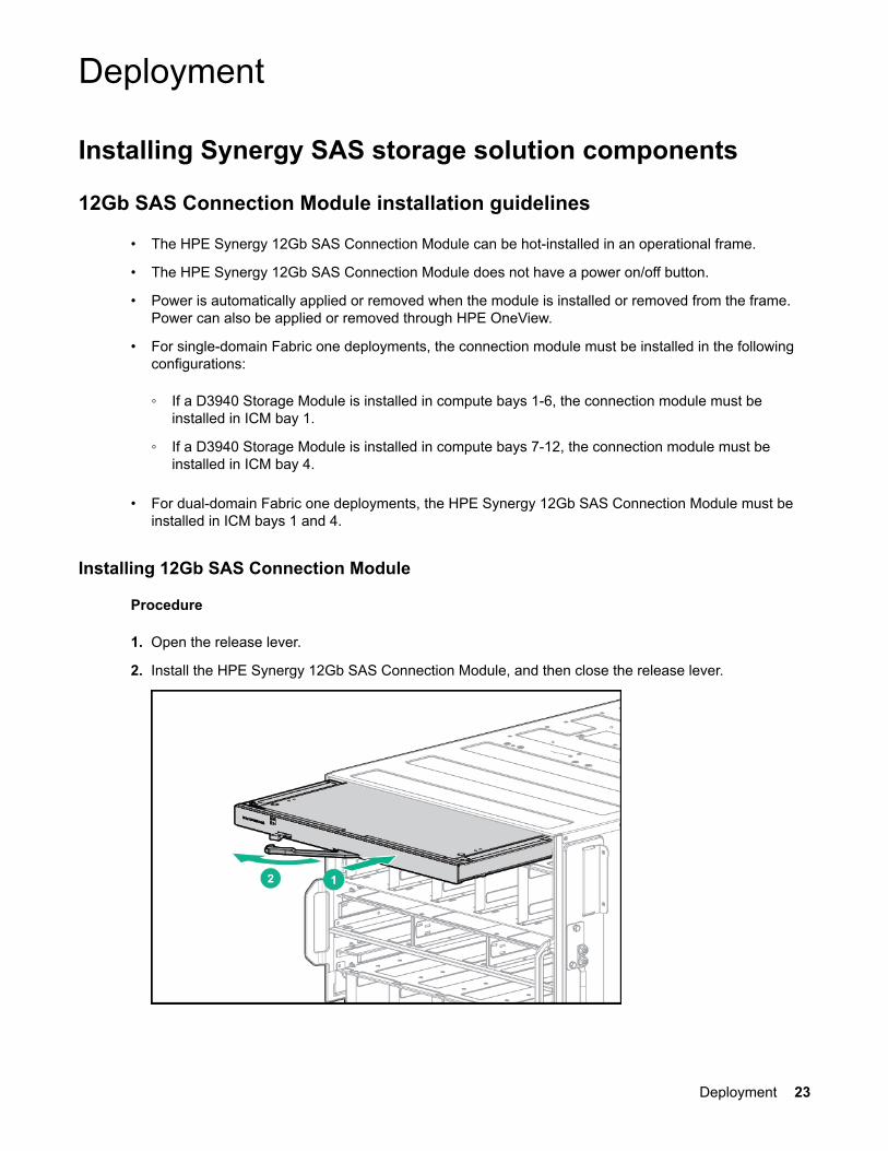
Installing 12Gb SAS Connection Module
Procedure
1. Open the release lever.
2. Install the HPE Synergy 12Gb SAS Connection Module, and then close the release lever.
Deployment 23
When installed in an operational frame, the module automatically powers up and performs a series ofPower On Self-Tests.
3. Observe the following actions during startup:
• All LEDs might flash amber, blue, off, and then green during the first two seconds while theconnection module is powering up.
• The green Health LED remains static when the frame link module powers up the SAS connectionmodule.
• Fans will slowly ramp up (9 minutes maximum) until the connection module firmware boots up.
4. If the Health LED is flashing amber or off, do one of the following:
• To ensure that the connection module is seated properly, remove the module from the frameInterconnect Bay and reinstall it by pressing firmly on the module and the locking latch handle.
• Verify that the frame has enough available power to power on the connection module.
• Verify that the connection module is installed in interconnect bays 1 or 4.
• Check the connection module status in HPE OneView.
D3940 Storage Module installation guidelines
• Installation of the D3940 Storage Module into the frame without drives requires one person.
• Installation of the D3940 Storage Module into the frame with drives requires two people.
• Install the D3940 Storage Module in any two adjoining frame bays.
• Make sure the storage module fits in the available frame bays.
• The drawer power LED will not illuminate green until a compute module containing one or more logicalJBODs that are assigned to the D3940 Storage Module is powered on.
• In single connection module configurations: if the SAS connection module is in ICM1, then the storagemodules are only supported in device bays 1-6.
• If the SAS connection module is in ICM4, then the D3940 Storage Modules are only supported indevice bays 7-12.
Installing D3940 Storage Module
Procedure
1. Prepare the storage module for installation by pressing down on the storage module handle releaselatch, which opens the storage module handle.
24 D3940 Storage Module installation guidelines
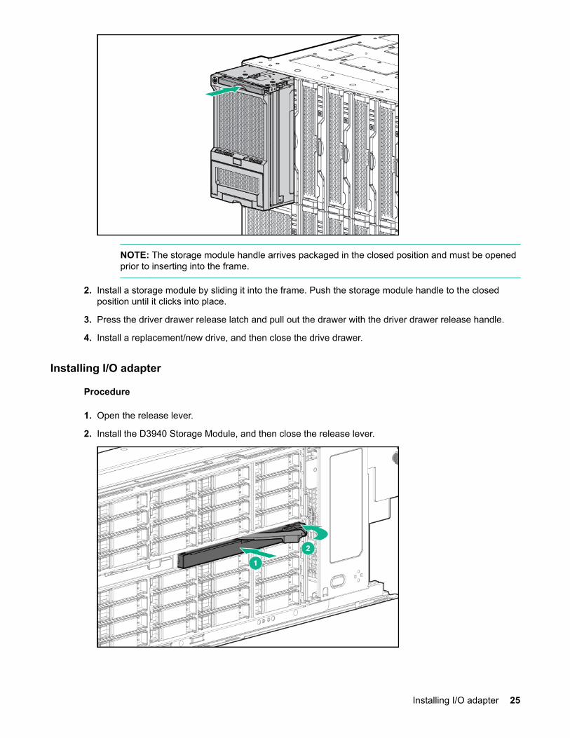
NOTE: The storage module handle arrives packaged in the closed position and must be openedprior to inserting into the frame.
2. Install a storage module by sliding it into the frame. Push the storage module handle to the closedposition until it clicks into place.
3. Press the driver drawer release latch and pull out the drawer with the driver drawer release handle.
4. Install a replacement/new drive, and then close the drive drawer.
Installing I/O adapter
Procedure
1. Open the release lever.
2. Install the D3940 Storage Module, and then close the release lever.
Installing I/O adapter 25
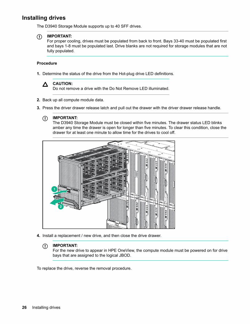
Installing drivesThe D3940 Storage Module supports up to 40 SFF drives.
IMPORTANT:For proper cooling, drives must be populated from back to front. Bays 33-40 must be populated firstand bays 1-8 must be populated last. Drive blanks are not required for storage modules that are notfully populated.
Procedure
1. Determine the status of the drive from the Hot-plug drive LED definitions.
CAUTION:Do not remove a drive with the Do Not Remove LED illuminated.
2. Back up all compute module data.
3. Press the driver drawer release latch and pull out the drawer with the driver drawer release handle.
IMPORTANT:The D3940 Storage Module must be closed within five minutes. The drawer status LED blinksamber any time the drawer is open for longer than five minutes. To clear this condition, close thedrawer for at least one minute to allow time for the drives to cool off.
4. Install a replacement / new drive, and then close the drive drawer.
IMPORTANT:For the new drive to appear in HPE OneView, the compute module must be powered on for drivebays that are assigned to the logical JBOD.
To replace the drive, reverse the removal procedure.
26 Installing drives
HPE Smart Array controller installation guidelines
• Make sure that mezzanine cards are installed in server mezzanine slots that map to the selectedSynergy frame interconnect bay.
• For the Synergy 480 compute module, it must occupy mezzanine slot 1.
• For the Synergy 660 compute module, it must occupy mezzanine slot 1 or mezzanine slot 4.
IMPORTANT:For more information about the association between the mezzanine bay and the interconnectbays, see the HPE Synergy 12000 Frame Setup and Installation Guide in the Hewlett PackardEnterprise Information Library (http://www.hpe.com/info/synergy-docs). Where you install themezzanine card determines where to install the interconnect modules.
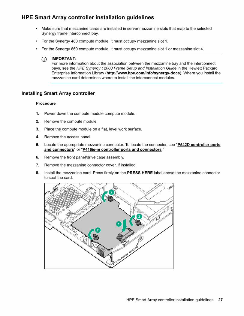
Installing Smart Array controller
Procedure
1. Power down the compute module compute module.
2. Remove the compute module.
3. Place the compute module on a flat, level work surface.
4. Remove the access panel.
5. Locate the appropriate mezzanine connector. To locate the connector, see "P542D controller portsand connectors" or "P416ie-m controller ports and connectors."
6. Remove the front panel/drive cage assembly.
7. Remove the mezzanine connector cover, if installed.
8. Install the mezzanine card. Press firmly on the PRESS HERE label above the mezzanine connectorto seat the card.
2
2
2
1
HPE Smart Array controller installation guidelines 27
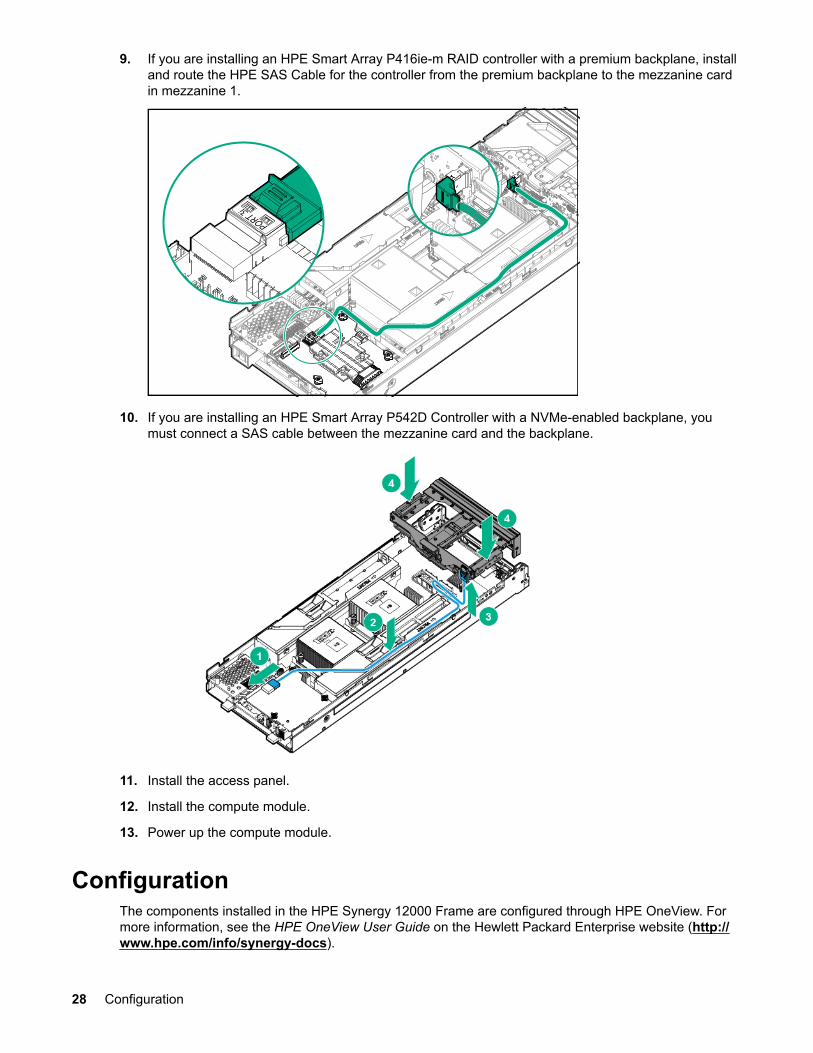
9. If you are installing an HPE Smart Array P416ie-m RAID controller with a premium backplane, installand route the HPE SAS Cable for the controller from the premium backplane to the mezzanine cardin mezzanine 1.
10. If you are installing an HPE Smart Array P542D Controller with a NVMe-enabled backplane, youmust connect a SAS cable between the mezzanine card and the backplane.
11. Install the access panel.
12. Install the compute module.
13. Power up the compute module.
ConfigurationThe components installed in the HPE Synergy 12000 Frame are configured through HPE OneView. Formore information, see the HPE OneView User Guide on the Hewlett Packard Enterprise website (http://www.hpe.com/info/synergy-docs).
28 Configuration
IMPORTANT:Hewlett Packard Enterprise recommends that you create regular backups, preferably once a dayand after you make hardware or software configuration changes in the managed environment.
Firmware bundleA firmware bundle, also known as an SPP, is a tested update package of firmware, drivers, and utilities.Firmware bundles allow you to update firmware on managed server blades and infrastructure (enclosuresand interconnects).
Creating a firmware bundle
Procedure
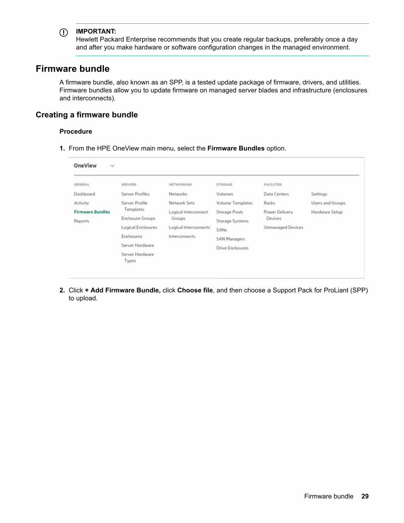
1. From the HPE OneView main menu, select the Firmware Bundles option.
2. Click + Add Firmware Bundle, click Choose file, and then choose a Support Pack for ProLiant (SPP)to upload.
Firmware bundle 29
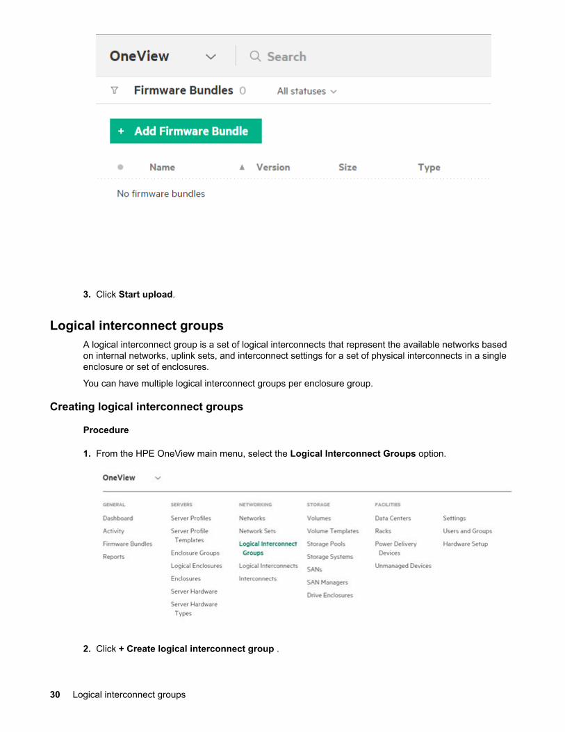
3. Click Start upload.
Logical interconnect groupsA logical interconnect group is a set of logical interconnects that represent the available networks basedon internal networks, uplink sets, and interconnect settings for a set of physical interconnects in a singleenclosure or set of enclosures.
You can have multiple logical interconnect groups per enclosure group.
Creating logical interconnect groups
Procedure
1. From the HPE OneView main menu, select the Logical Interconnect Groups option.
2. Click + Create logical interconnect group .
30 Logical interconnect groups
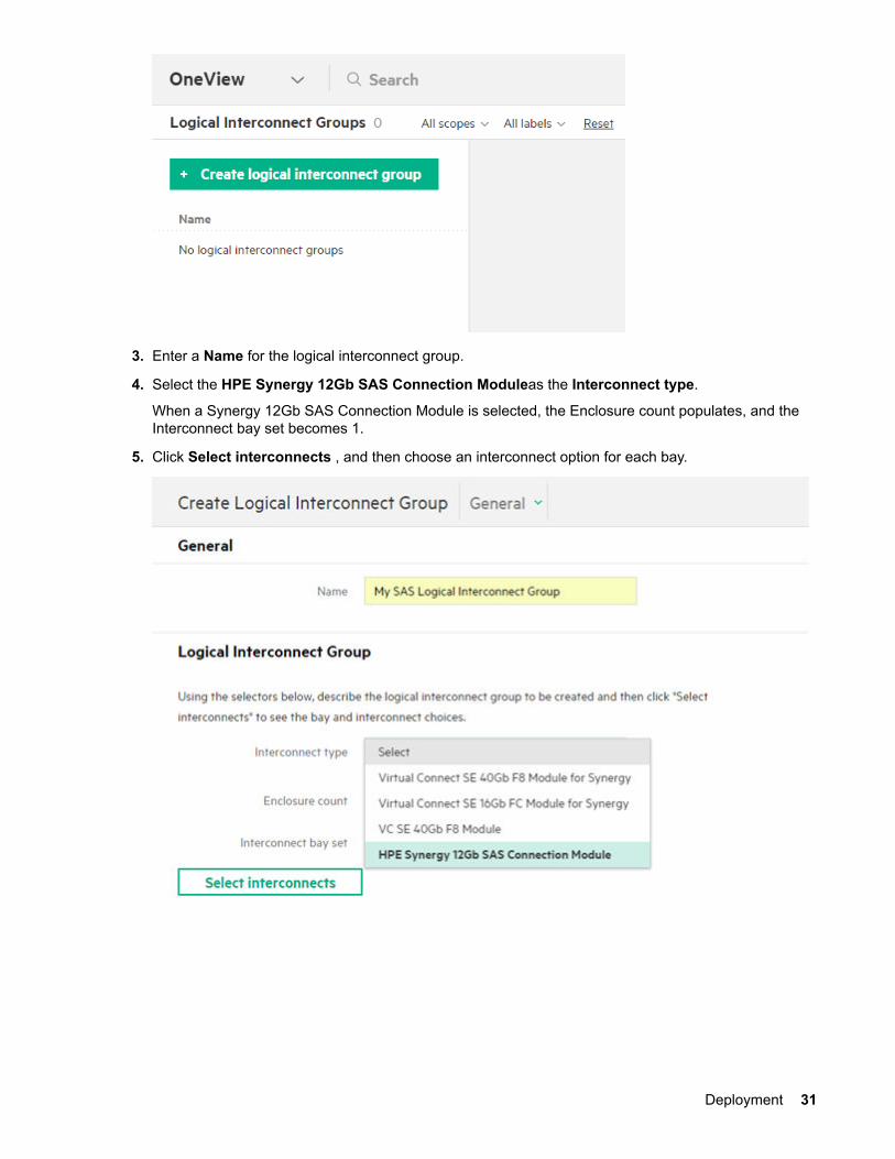
3. Enter a Name for the logical interconnect group.
4. Select the HPE Synergy 12Gb SAS Connection Moduleas the Interconnect type.
When a Synergy 12Gb SAS Connection Module is selected, the Enclosure count populates, and theInterconnect bay set becomes 1.
5. Click Select interconnects , and then choose an interconnect option for each bay.
Deployment 31
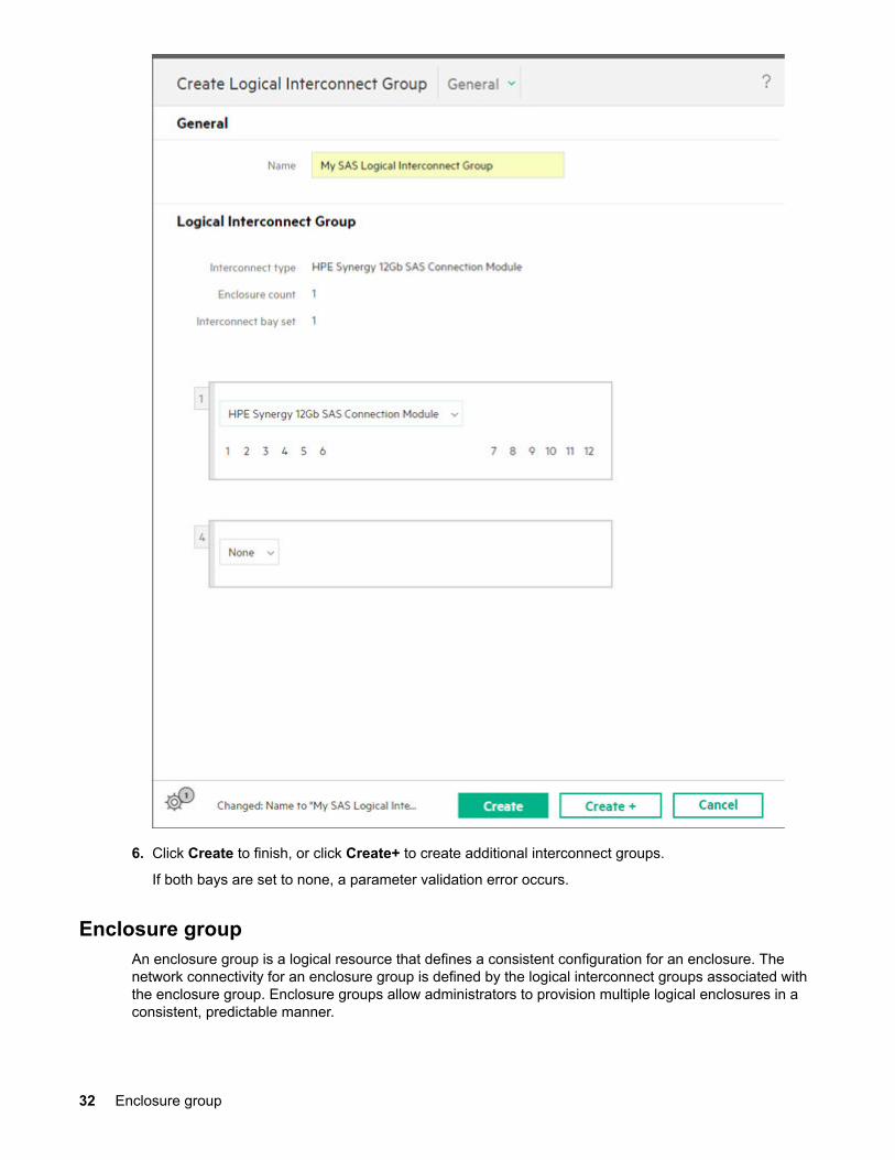
6. Click Create to finish, or click Create+ to create additional interconnect groups.
If both bays are set to none, a parameter validation error occurs.
Enclosure groupAn enclosure group is a logical resource that defines a consistent configuration for an enclosure. Thenetwork connectivity for an enclosure group is defined by the logical interconnect groups associated withthe enclosure group. Enclosure groups allow administrators to provision multiple logical enclosures in aconsistent, predictable manner.
32 Enclosure group
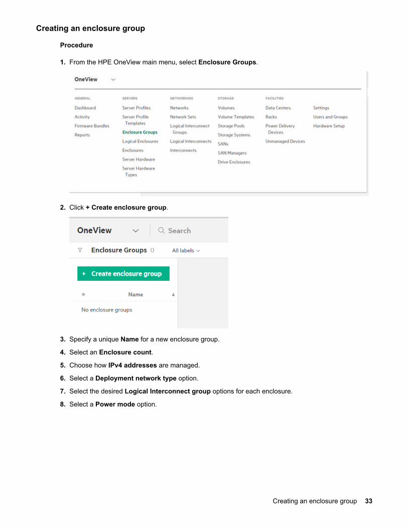
Creating an enclosure group
Procedure
1. From the HPE OneView main menu, select Enclosure Groups.
2. Click + Create enclosure group.
3. Specify a unique Name for a new enclosure group.
4. Select an Enclosure count.
5. Choose how IPv4 addresses are managed.
6. Select a Deployment network type option.
7. Select the desired Logical Interconnect group options for each enclosure.
8. Select a Power mode option.
Creating an enclosure group 33
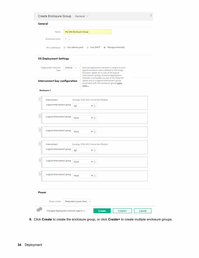
9. Click Create to create the enclosure group, or click Create+ to create multiple enclosure groups.
34 Deployment
If you need assistance with your entries, see the Enclosure Groups screen details section of the HPEOneView help (http://www.hpe.com/info/oneview/docs).
Logical enclosureA logical enclosure represents a logical view of a single enclosure with an enclosure group serving as atemplate. If the intended configuration in the logical enclosure does not match the actual configuration onthe enclosure, the logical enclosure becomes inconsistent.
A logical enclosure is automatically created when a c7000 enclosure is added.
You must manually create a logical enclosure for HPE Synergy 12000 Frame enclosures.
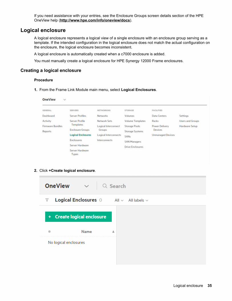
Creating a logical enclosure
Procedure
1. From the Frame Link Module main menu, select Logical Enclosures.
2. Click +Create logical enclosure.
Logical enclosure 35
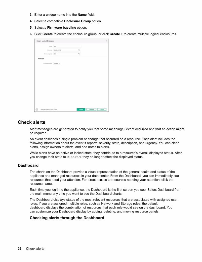
3. Enter a unique name into the Name field.
4. Select a compatible Enclosure Group option.
5. Select a Firmware baseline option.
6. Click Create to create the enclosure group, or click Create + to create multiple logical enclosures.
Check alertsAlert messages are generated to notify you that some meaningful event occurred and that an action mightbe required.
An event describes a single problem or change that occurred on a resource. Each alert includes thefollowing information about the event it reports: severity, state, description, and urgency. You can clearalerts, assign owners to alerts, and add notes to alerts.
While alerts have an active or locked state, they contribute to a resource’s overall displayed status. Afteryou change their state to Cleared, they no longer affect the displayed status.
DashboardThe charts on the Dashboard provide a visual representation of the general health and status of theappliance and managed resources in your data center. From the Dashboard, you can immediately seeresources that need your attention. For direct access to resources needing your attention, click theresource name.
Each time you log in to the appliance, the Dashboard is the first screen you see. Select Dashboard fromthe main menu any time you want to see the Dashboard charts.
The Dashboard displays status of the most relevant resources that are associated with assigned userroles. If you are assigned multiple roles, such as Network and Storage roles, the defaultdashboard displays the combination of resources that each role would see on the dashboard. Youcan customize your Dashboard display by adding, deleting, and moving resource panels.
Checking alerts through the Dashboard
36 Check alerts
Procedure
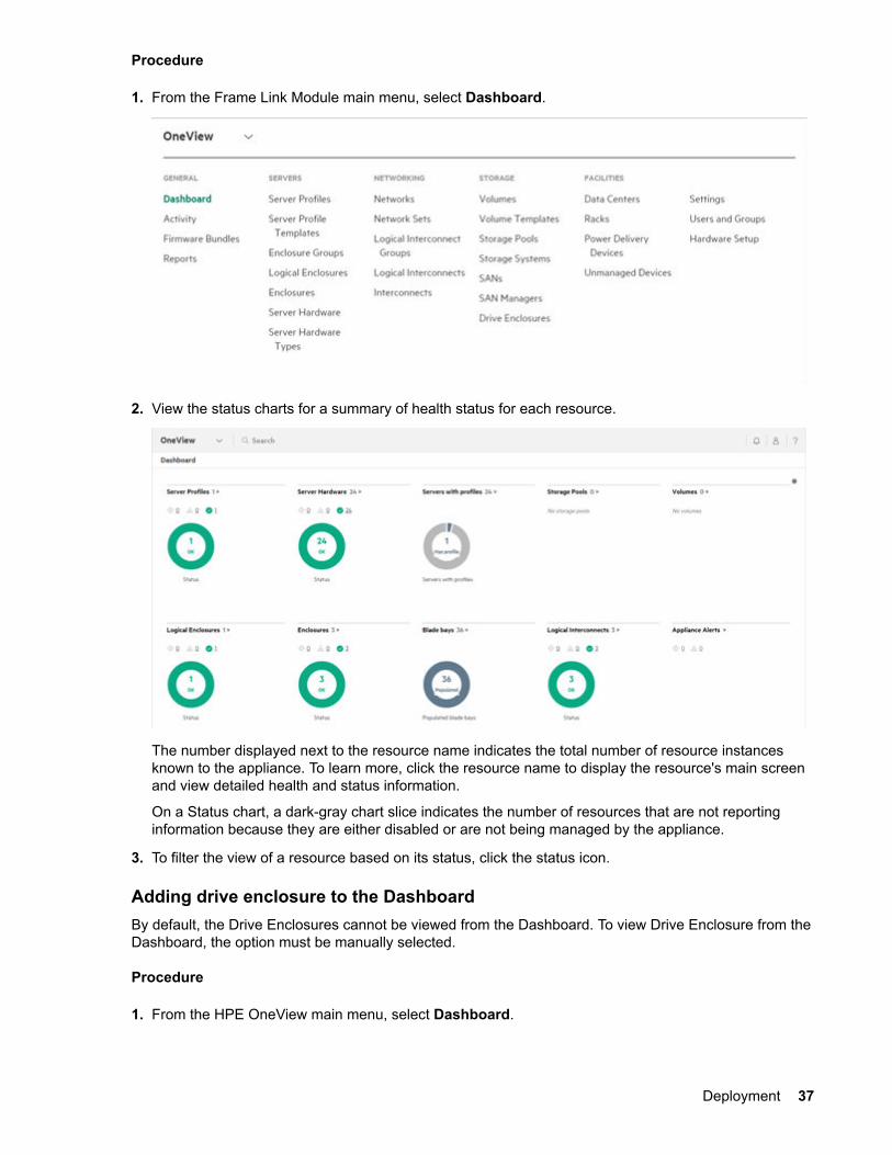
1. From the Frame Link Module main menu, select Dashboard.
2. View the status charts for a summary of health status for each resource.
The number displayed next to the resource name indicates the total number of resource instancesknown to the appliance. To learn more, click the resource name to display the resource's main screenand view detailed health and status information.
On a Status chart, a dark-gray chart slice indicates the number of resources that are not reportinginformation because they are either disabled or are not being managed by the appliance.
3. To filter the view of a resource based on its status, click the status icon.
Adding drive enclosure to the DashboardBy default, the Drive Enclosures cannot be viewed from the Dashboard. To view Drive Enclosure from theDashboard, the option must be manually selected.
Procedure
1. From the HPE OneView main menu, select Dashboard.
Deployment 37
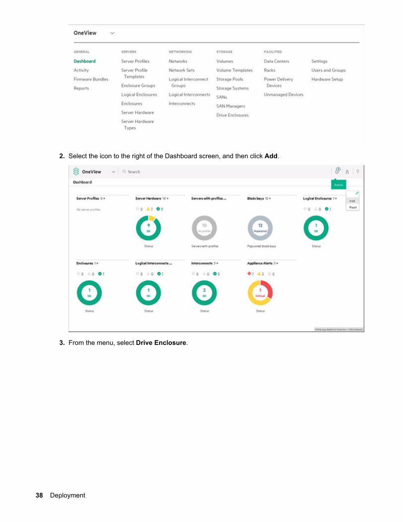
2. Select the icon to the right of the Dashboard screen, and then click Add.
3. From the menu, select Drive Enclosure.
38 Deployment
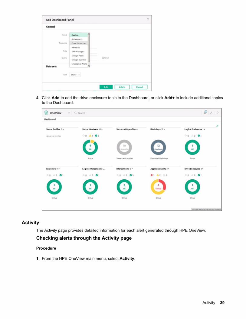
4. Click Add to add the drive enclosure topic to the Dashboard, or click Add+ to include additional topicsto the Dashboard.
ActivityThe Activity page provides detailed information for each alert generated through HPE OneView.
Checking alerts through the Activity page
Procedure
1. From the HPE OneView main menu, select Activity.
Activity 39
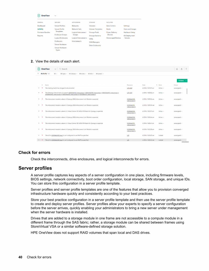
2. View the details of each alert.
Check for errorsCheck the interconnects, drive enclosures, and logical interconnects for errors.
Server profilesA server profile captures key aspects of a server configuration in one place, including firmware levels,BIOS settings, network connectivity, boot order configuration, local storage, SAN storage, and unique IDs.You can store this configuration in a server profile template.
Server profiles and server profile templates are one of the features that allow you to provision convergedinfrastructure hardware quickly and consistently according to your best practices.
Store your best practice configuration in a server profile template and then use the server profile templateto create and deploy server profiles. Server profiles allow your experts to specify a server configurationbefore the server arrives, quickly enabling your administrators to bring a new server under managementwhen the server hardware is installed.
Drives that are added to a storage module in one frame are not accessible to a compute module in adifferent frame through the SAS fabric; rather, a storage module can be shared between frames usingStoreVirtual VSA or a similar software-defined storage solution.
HPE OneView does not support RAID volumes that span local and DAS drives.
40 Check for errors
Creating server profiles
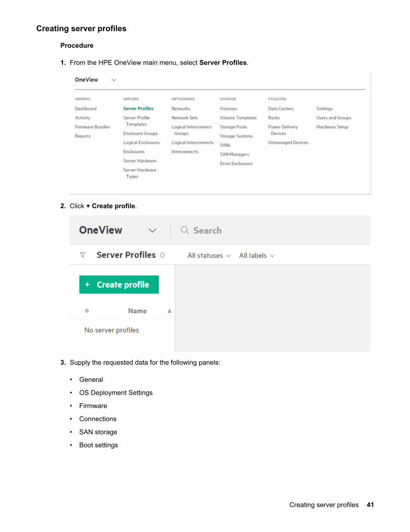
Procedure
1. From the HPE OneView main menu, select Server Profiles.
2. Click + Create profile.
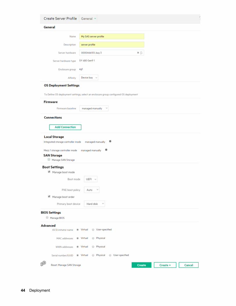
3. Supply the requested data for the following panels:
• General
• OS Deployment Settings
• Firmware
• Connections
• SAN storage
• Boot settings
Creating server profiles 41
• BIOS settings
• Advanced
4. Under Local Storage, select the icon next to the storage controller mode.
5. Choose one of the following local storage modes:
• Managed manually—Indicates that the storage controller is managed by the user outside of HPEOneView.
• RAID—Indicates HPE OneView configures the storage controller into RAID mode.
• HBA—Indicates HPE OneView manages the controller into HBA mode.
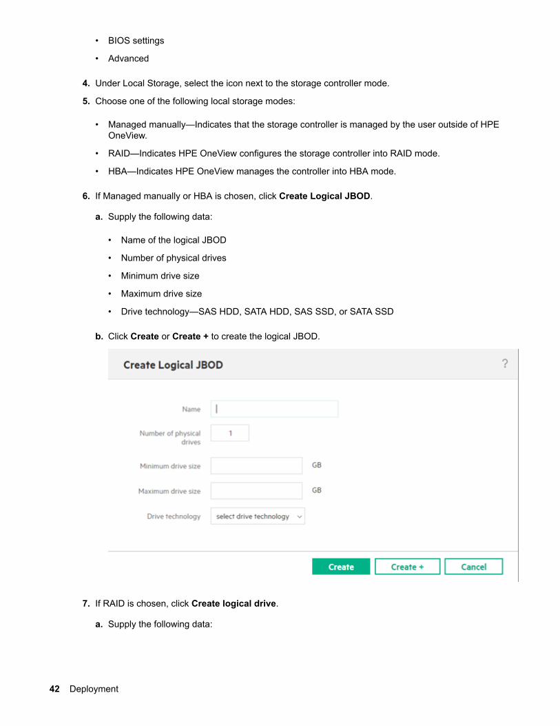
6. If Managed manually or HBA is chosen, click Create Logical JBOD.
a. Supply the following data:
• Name of the logical JBOD
• Number of physical drives
• Minimum drive size
• Maximum drive size
• Drive technology—SAS HDD, SATA HDD, SAS SSD, or SATA SSD
b. Click Create or Create + to create the logical JBOD.
7. If RAID is chosen, click Create logical drive.
a. Supply the following data:
42 Deployment
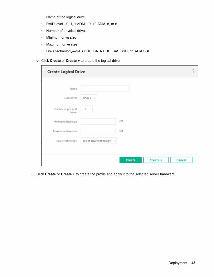
• Name of the logical drive
• RAID level—0, 1, 1 ADM, 10, 10 ADM, 5, or 6
• Number of physical drives
• Minimum drive size
• Maximum drive size
• Drive technology—SAS HDD, SATA HDD, SAS SSD, or SATA SSD
b. Click Create or Create + to create the logical drive.
8. Click Create or Create + to create the profile and apply it to the selected server hardware.
Deployment 43
44 Deployment
For more information about configuring the D3940 storage module using HPE OneView, see the HewlettPackard Enterprise website (http://www.hpe.com/info/oneview/docs).
Delete or force delete a server profileYou can delete a server profile that you no longer need. After you delete the server profile, the serverhardware is available for another server profile. Network connectivity is lost on the server if the profile hada network configuration in it.
If you are having connectivity issues with a server profile or if a remove action fails for a server profile,you can forcibly delete it from the appliance.
IMPORTANT:
Before deleting a profile with local storage settings, back up any important data.
Logical JBODs and logical drives on mezzanine controllers are deleted when the profile is deletedand their data will not be recoverable. It is also recommended that you create a backup of the HPEOneView appliance before deleting such profiles as a way to recover access to the physical drives ifthe profile is deleted accidentally.
IMPORTANT:
Deleting a server profile that defines nonpermanent volumes will result in those volumes beingdeleted from the storage system. Consider obtaining a backup of the data on nonpermanentvolumes before deleting the profile.
NOTE:
Deleting a server profile with SAN volumes attached can fail if there are communication issues withthe storage system. In such cases, retry deleting the profile or clean up the volumes and relatedobjects from the storage system device manager and forcibly delete the profile.
Prerequisites
• Privileges: Infrastructure administrator or Server administrator
• The selected server hardware is powered off
Procedure
1. From the main menu, select Server Profiles.
2. In the master pane, select the server profile you want to delete.
NOTE:
To run this action on more than one object, use the Shift or Ctrl keys to select multiple objects inthe master pane.
3. Select Actions > Delete.
4. Optional: Select Force delete server profile.
Delete or force delete a server profile 45
IMPORTANT:
Forcibly deleting a server profile will ignore any errors that might occur. Ignoring errors can resultin the server hardware and interconnects to be in a state that will prohibit future use of theenclosure bay, or cause networking problems if other profiles use the same MAC addresses orWWNs as this profile.
After forcibly deleting a server profile, any server hardware assigned to it will appear asunassigned.
Drive erase does not occur if logical JBODs that have drive erase specified fail to delete.
5. Review the confirmation message, and click Yes, delete.
6. Verify in master pane that the profile was deleted.
InventoryInterconnect
You do not add interconnects to the appliance, you add enclosures and the interconnects in them areadded to the appliance automatically.
When you add an enclosure, the interconnects in the enclosure are added if they are members of alogical interconnect group of the enclosure group used to add the enclosure. If you remove an enclosurefrom the domain, the interconnects are also removed from the domain.
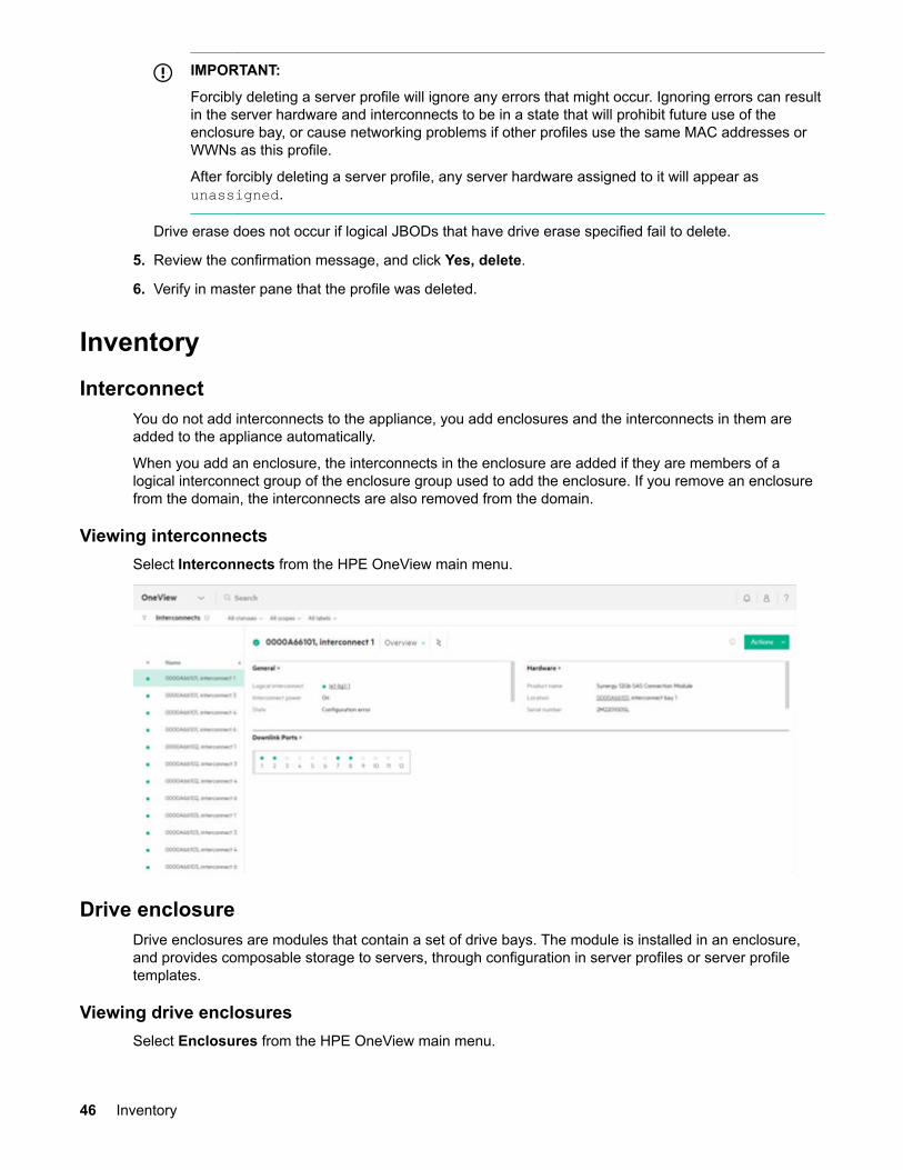
Viewing interconnectsSelect Interconnects from the HPE OneView main menu.
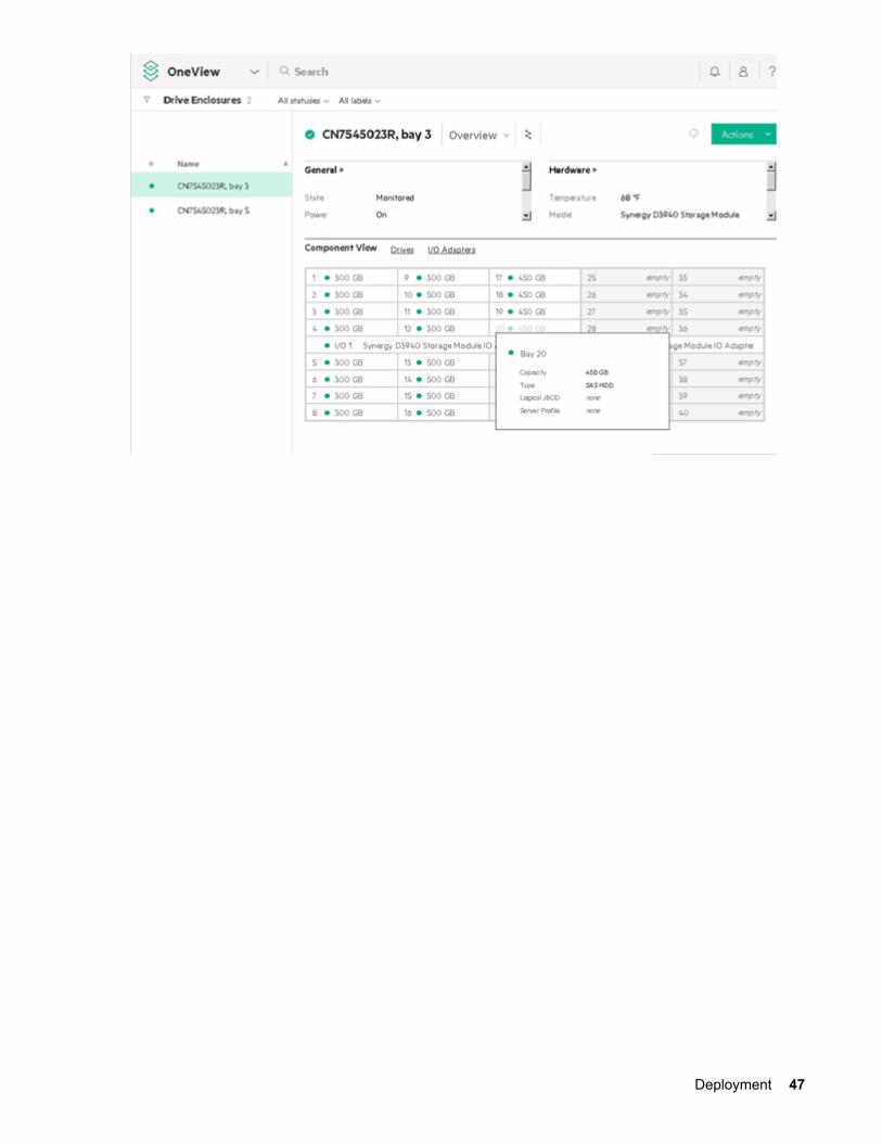
Drive enclosureDrive enclosures are modules that contain a set of drive bays. The module is installed in an enclosure,and provides composable storage to servers, through configuration in server profiles or server profiletemplates.
Viewing drive enclosuresSelect Enclosures from the HPE OneView main menu.
46 Inventory
Deployment 47
OperationsStatus event notifications
An alert message informs you that an event occurred that requires your attention.
An alert message is an important troubleshooting tool. It indicates when an event occurred and whichresource reported it. An alert message provides details about the event and suggests a solution.
If a user- or system-initiated action is complete, there is a record for it. If an action is not complete, youcan see which subtasks were completed or are still running and which subtasks are interrupted orstopped.
You can view all activities, filter the activities by several criteria to view only those activities you want tosee, or search for a specific activity.
You can assign alerts to the appropriate administrator for their timely resolution. When issues areinvestigated and resolved, you can clear them so they no longer require your attention.
You can annotate alert messages to keep a historical record of issues and their resolutions, or you cannote a decision that affected the alert resolution.
You can see status event notifications through the HPE OneView GUI, RESTapi, or email.
Receiving event notifications through HPE OneView GUI
Procedure
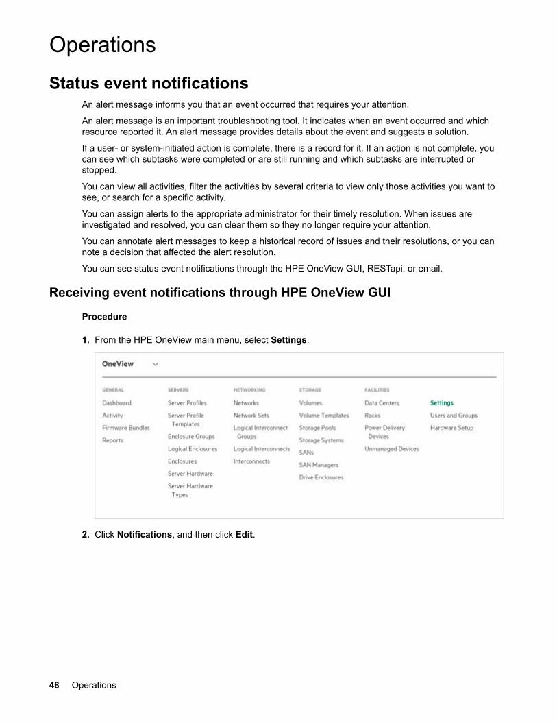
1. From the HPE OneView main menu, select Settings.
2. Click Notifications, and then click Edit.
48 Operations
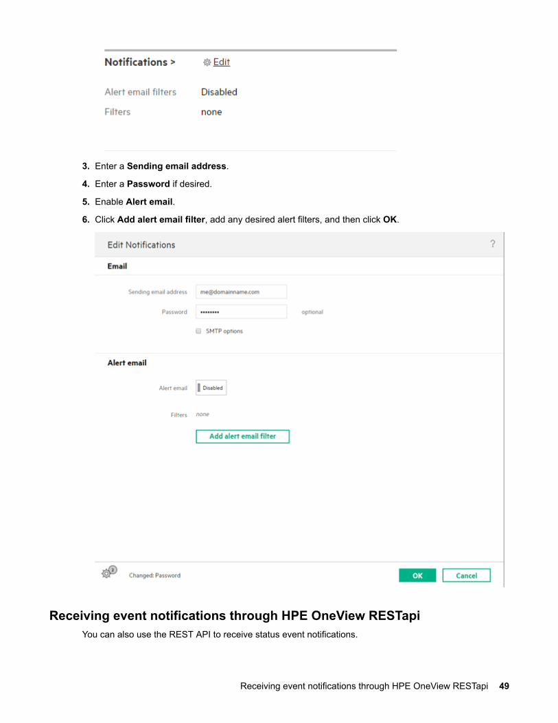
3. Enter a Sending email address.
4. Enter a Password if desired.
5. Enable Alert email.
6. Click Add alert email filter, add any desired alert filters, and then click OK.
Receiving event notifications through HPE OneView RESTapiYou can also use the REST API to receive status event notifications.
Receiving event notifications through HPE OneView RESTapi 49
REST API: /rest/alertsFor more information, see the HPE OneView REST API Reference.
FirmwareFirmware is preinstalled on each module in the factory, but an updated, alternative, or preferred versionmay be available.
The installed firmware version is displayed in HPE OneView near the center of the Synergy 12Gb SASConnection Module. Access HPE OneView and make note of the installed firmware version on eachconnection module.
IMPORTANT:When two HPE Synergy 12Gb SAS Connection Modules are installed in interconnect bays 1 and 4of a frame, make sure that they are running the same firmware version.
Updating the firmware
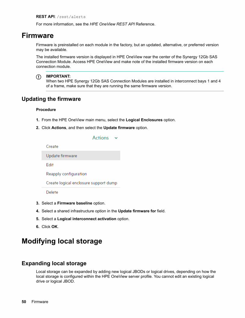
Procedure
1. From the HPE OneView main menu, select the Logical Enclosures option.
2. Click Actions, and then select the Update firmware option.
3. Select a Firmware baseline option.
4. Select a shared infrastructure option in the Update firmware for field.
5. Select a Logical interconnect activation option.
6. Click OK.
Modifying local storage
Expanding local storageLocal storage can be expanded by adding new logical JBODs or logical drives, depending on how thelocal storage is configured within the HPE OneView server profile. You cannot edit an existing logicaldrive or logical JBOD.
50 Firmware
There are three ways to expand local storage:
• Manually managed
• HBA
• RAID
Expanding local storage also includes adding drives to the storage module when there are empty bays.Extra storage modules can also be added to an existing HPE Synergy 12000 Frame.
It is important to note the following when adding drives to expand local storage:
• Drives added to the storage module are not automatically zoned to compute module and remainunassigned until added to a server profile.
• Drives will be detected automatically in the Composer.
Manually managedA user can manually manage expanding local storage by doing the following:
• Adding additional logical JBODs.
• Using a local HPSSA tool to perform an array expansion and logical drive extension of existing logicaldrives. Doing this will increase the number of member disks and extend the logical drive to utilize thecapacity of the larger array.
HBAAdd additional logical JBODs in HBA mode.
RAIDA user can expand local storage using the RAID mode by doing one of the following:
• Adding additional logical drives.
• Deleting an existing logical drive and creating a larger logical drive. This will backup and restore thedrive data.
Editing server profile
IMPORTANT:The server must be offline and powered down before editing a server profile.
Replacing Synergy SAS storage solution componentsReplacing 12Gb SAS Connection Module
Removing the failed 12Gb SAS Connection Module
Manually managed 51
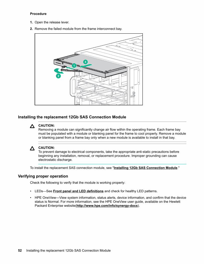
Procedure
1. Open the release lever.
2. Remove the failed module from the frame interconnect bay.
Installing the replacement 12Gb SAS Connection Module
CAUTION:Removing a module can significantly change air flow within the operating frame. Each frame baymust be populated with a module or blanking panel for the frame to cool properly. Remove a moduleor blanking panel from a frame bay only when a new module is available to install in that bay.
CAUTION:To prevent damage to electrical components, take the appropriate anti-static precautions beforebeginning any installation, removal, or replacement procedure. Improper grounding can causeelectrostatic discharge.
To install the replacement SAS connection module, see "Installing 12Gb SAS Connection Module."
Verifying proper operationCheck the following to verify that the module is working properly:
• LEDs—See Front panel and LED definitions and check for healthy LED patterns.
• HPE OneView—View system information, status alerts, device information, and confirm that the devicestatus is Normal. For more information, see the HPE OneView user guide, available on the HewlettPackard Enterprise website(http://www.hpe.com/info/synergy-docs).
52 Installing the replacement 12Gb SAS Connection Module
Replacing Synergy D3940 Storage Module Enclosure
Powering down the D3940 Storage ModuleTo disable the power LED, you must power down all the assigned compute modules. Actions within HPEOneView allow you to power down the D3940 Storage Module.
Removing the D3940 Storage Module
WARNING:To reduce the risk of personal injury from hot surfaces, allow the drives and the internal systemcomponents to cool before touching them.
CAUTION:To prevent damage to electrical components, properly ground the D3940 Storage Module beforebeginning any installation procedure. Improper grounding can cause ESD.
Procedure
1. Identify the proper D3940 Storage Module.
2. Label the drive bay locations for each drive.
3. Remove all the drives.
IMPORTANT:The replacement D3940 Storage Module must not contain drives.
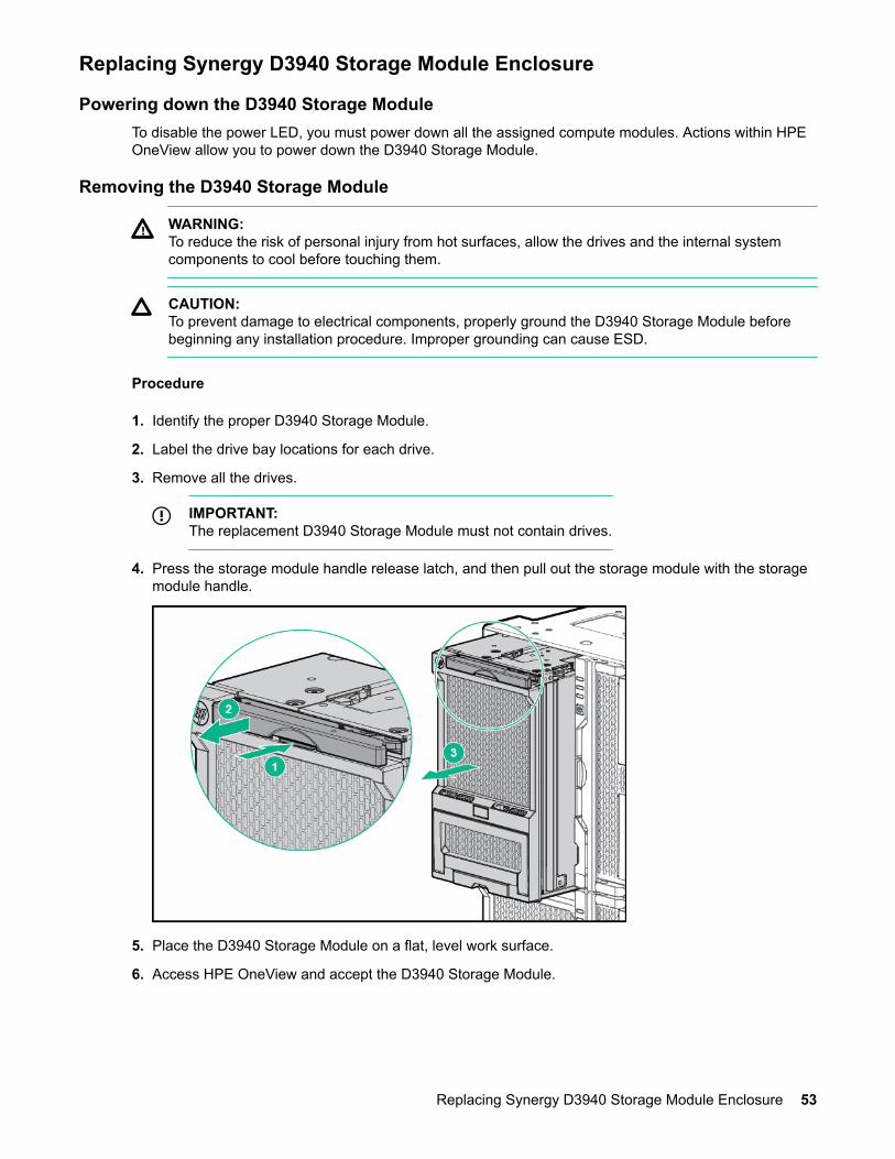
4. Press the storage module handle release latch, and then pull out the storage module with the storagemodule handle.
5. Place the D3940 Storage Module on a flat, level work surface.
6. Access HPE OneView and accept the D3940 Storage Module.
Replacing Synergy D3940 Storage Module Enclosure 53
IMPORTANT:HPE OneView remembers missing drive enclosures that contain one or more logical JBODs. Toclear this condition, delete all the server profiles that use the missing drive enclosure.
a. From the HPE OneView dashboard, select logical interconnects.
b. From logical interconnects, select the SAS logical interconnect.
c. View the alerts.
d. Select the missing drive enclosure alert.
e. Select the action to replace the missing drive enclosure.
f. From the replace missing drive enclosure pop-up screen, select the replacement D3940.
g. Click Yes, replace.
h. Monitor the task progress to verify that it has completed.
7. Add all the drives back into the same drive bay locations.
8. Power up the servers.
Installing the replacement D3940 Storage ModuleTo install the replacement storage module, see "Installing D3940 Storage Module."
The drawer power LED will not illuminate green until a compute module containing one or more logicalJBODs that are assigned to the D3940 Storage Module is powered on.
Verifying proper operationCheck the following to verify that the module is working properly:
• LEDs—See Front panel and LED definitions and check for healthy LED patterns.
• HPE OneView—View system information, status alerts, device information, and confirm that the devicestatus is Normal. For more information, see the HPE OneView user guide, available on the HewlettPackard Enterprise website (http://www.hpe.com/info/synergy-docs).
Replacing D3940 I/O adapter
Removing the failed D3940 I/O adapter
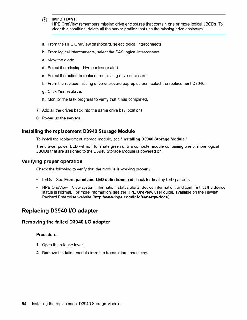
Procedure
1. Open the release lever.
2. Remove the failed module from the frame interconnect bay.
54 Installing the replacement D3940 Storage Module
Installing the replacement D3940 I/O adapterTo install the replacement I/O adapter, see "Installing I/O adapter."
Verifying proper operationCheck the following to verify that the module is working properly:
• LEDs—See Front panel and LED definitions and check for healthy LED patterns.
• HPE OneView—View system information, status alerts, device information, and confirm that the devicestatus is Normal. For more information, see the HPE OneView user guide, available on the HewlettPackard Enterprise website (http://www.hpe.com/info/synergy-docs).
Installing the replacement D3940 I/O adapter 55
Electrostatic dischargePreventing electrostatic discharge
To prevent damaging the system, be aware of the precautions you must follow when setting up thesystem or handling parts. A discharge of static electricity from a finger or other conductor may damagesystem boards or other static-sensitive devices. This type of damage may reduce the life expectancy ofthe device.
To prevent electrostatic damage:
• Avoid hand contact by transporting and storing products in static-safe containers.
• Keep electrostatic-sensitive parts in their containers until they arrive at static-free workstations.
• Place parts on a grounded surface before removing them from their containers.
• Avoid touching pins, leads, or circuitry.
• Always be properly grounded when touching a static-sensitive component or assembly.
Grounding methods to prevent electrostatic dischargeSeveral methods are used for grounding. Use one or more of the following methods when handling orinstalling electrostatic-sensitive parts:
• Use a wrist strap connected by a ground cord to a grounded workstation or computer chassis. Wriststraps are flexible straps with a minimum of 1 megohm ±10 percent resistance in the ground cords. Toprovide proper ground, wear the strap snug against the skin.
• Use heel straps, toe straps, or boot straps at standing workstations. Wear the straps on both feetwhen standing on conductive floors or dissipating floor mats.
• Use conductive field service tools.
• Use a portable field service kit with a folding static-dissipating work mat.
If you do not have any of the suggested equipment for proper grounding, have an authorized resellerinstall the part.
For more information on static electricity or assistance with product installation, contact an authorizedreseller.
56 Electrostatic discharge
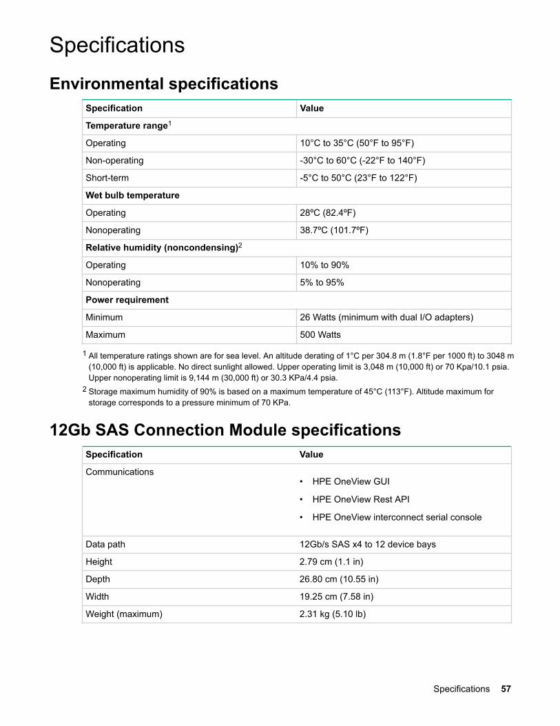
SpecificationsEnvironmental specifications
Specification Value
Temperature range1
Operating 10°C to 35°C (50°F to 95°F)
Non-operating -30°C to 60°C (-22°F to 140°F)
Short-term -5°C to 50°C (23°F to 122°F)
Wet bulb temperature
Operating 28ºC (82.4ºF)
Nonoperating 38.7ºC (101.7ºF)
Relative humidity (noncondensing)2
Operating 10% to 90%
Nonoperating 5% to 95%
Power requirement
Minimum 26 Watts (minimum with dual I/O adapters)
Maximum 500 Watts
1 All temperature ratings shown are for sea level. An altitude derating of 1°C per 304.8 m (1.8°F per 1000 ft) to 3048 m(10,000 ft) is applicable. No direct sunlight allowed. Upper operating limit is 3,048 m (10,000 ft) or 70 Kpa/10.1 psia.Upper nonoperating limit is 9,144 m (30,000 ft) or 30.3 KPa/4.4 psia.
2 Storage maximum humidity of 90% is based on a maximum temperature of 45°C (113°F). Altitude maximum forstorage corresponds to a pressure minimum of 70 KPa.
12Gb SAS Connection Module specificationsSpecification Value
Communications• HPE OneView GUI
• HPE OneView Rest API
• HPE OneView interconnect serial console
Data path 12Gb/s SAS x4 to 12 device bays
Height 2.79 cm (1.1 in)
Depth 26.80 cm (10.55 in)
Width 19.25 cm (7.58 in)
Weight (maximum) 2.31 kg (5.10 lb)
Specifications 57
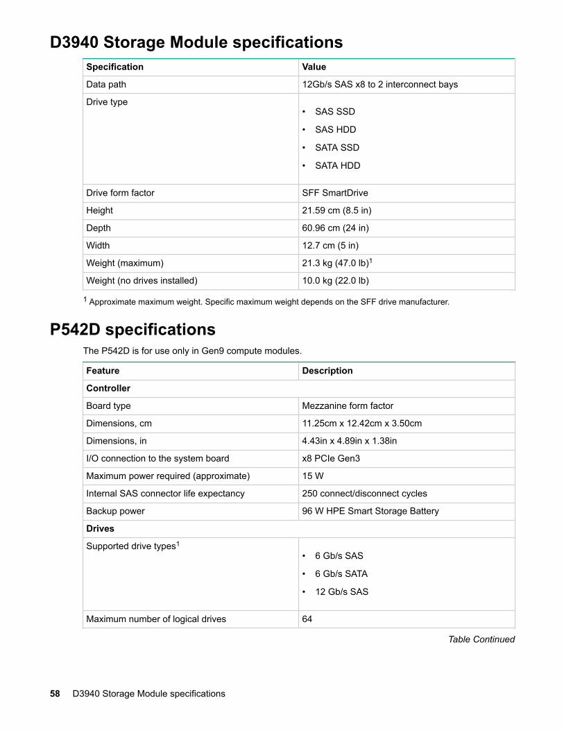
D3940 Storage Module specificationsSpecification Value
Data path 12Gb/s SAS x8 to 2 interconnect bays
Drive type• SAS SSD
• SAS HDD
• SATA SSD
• SATA HDD
Drive form factor SFF SmartDrive
Height 21.59 cm (8.5 in)
Depth 60.96 cm (24 in)
Width 12.7 cm (5 in)
Weight (maximum) 21.3 kg (47.0 lb)1
Weight (no drives installed) 10.0 kg (22.0 lb)
1 Approximate maximum weight. Specific maximum weight depends on the SFF drive manufacturer.
P542D specificationsThe P542D is for use only in Gen9 compute modules.
Feature Description
Controller
Board type Mezzanine form factor
Dimensions, cm 11.25cm x 12.42cm x 3.50cm
Dimensions, in 4.43in x 4.89in x 1.38in
I/O connection to the system board x8 PCIe Gen3
Maximum power required (approximate) 15 W
Internal SAS connector life expectancy 250 connect/disconnect cycles
Backup power 96 W HPE Smart Storage Battery
Drives
Supported drive types1
• 6 Gb/s SAS
• 6 Gb/s SATA
• 12 Gb/s SAS
Maximum number of logical drives 64
Table Continued
58 D3940 Storage Module specifications
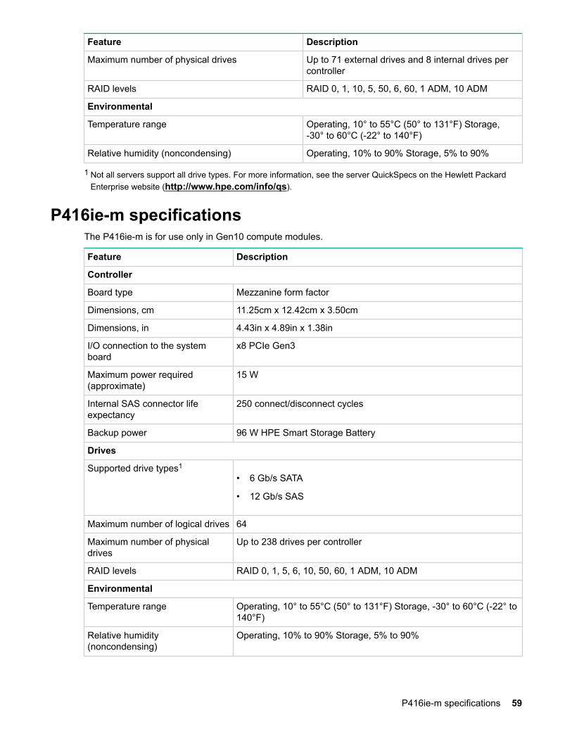
Feature Description
Maximum number of physical drives Up to 71 external drives and 8 internal drives percontroller
RAID levels RAID 0, 1, 10, 5, 50, 6, 60, 1 ADM, 10 ADM
Environmental
Temperature range Operating, 10° to 55°C (50° to 131°F) Storage,-30° to 60°C (-22° to 140°F)
Relative humidity (noncondensing) Operating, 10% to 90% Storage, 5% to 90%
1 Not all servers support all drive types. For more information, see the server QuickSpecs on the Hewlett PackardEnterprise website (http://www.hpe.com/info/qs).
P416ie-m specificationsThe P416ie-m is for use only in Gen10 compute modules.
Feature Description
Controller
Board type Mezzanine form factor
Dimensions, cm 11.25cm x 12.42cm x 3.50cm
Dimensions, in 4.43in x 4.89in x 1.38in
I/O connection to the systemboard
x8 PCIe Gen3
Maximum power required(approximate)
15 W
Internal SAS connector lifeexpectancy
250 connect/disconnect cycles
Backup power 96 W HPE Smart Storage Battery
Drives
Supported drive types1
• 6 Gb/s SATA
• 12 Gb/s SAS
Maximum number of logical drives 64
Maximum number of physicaldrives
Up to 238 drives per controller
RAID levels RAID 0, 1, 5, 6, 10, 50, 60, 1 ADM, 10 ADM
Environmental
Temperature range Operating, 10° to 55°C (50° to 131°F) Storage, -30° to 60°C (-22° to140°F)
Relative humidity(noncondensing)
Operating, 10% to 90% Storage, 5% to 90%
P416ie-m specifications 59

1 Not all servers support all drive types. For more information, see the server QuickSpecs on the Hewlett PackardEnterprise website (http://www.hpe.com/info/qs).
60 Specifications
Documentation and troubleshooting resourcesfor HPE SynergyDocumentation and troubleshooting resources for HPESynergy
HPE Synergy documentationThe Hewlett Packard Enterprise Information Library (www.hpe.com/info/synergy-docs) is a task-basedrepository. It includes installation instructions, user guides, maintenance and service guides, bestpractices, and links to additional resources. Use this website to obtain the latest documentation, including:
• Learning about HPE Synergy technology
• Installing and cabling HPE Synergy
• Updating the HPE Synergy components
• Using and managing HPE Synergy
• Troubleshooting HPE Synergy
HPE Synergy Configuration and Compatibility GuideThe HPE Synergy Configuration and Compatibility Guide is in the Hewlett Packard Enterprise InformationLibrary (www.hpe.com/info/synergy-docs). It provides an overview of HPE Synergy management andfabric architecture, detailed hardware component identification and configuration, and cabling examples.
HPE Synergy Frame Link Module User GuideThe HPE Synergy Frame Link Module User Guide is in the Hewlett Packard Enterprise InformationLibrary (www.hpe.com/info/synergy-docs). It outlines frame link module management, configuration,and security.
HPE OneView User Guide for HPE SynergyThe HPE OneView User Guide for HPE Synergy is in the Hewlett Packard Enterprise Information Library(www.hpe.com/info/synergy-docs). It describes resource features, planning tasks, configuration quickstart tasks, navigational tools for the graphical user interface, and more support and reference informationfor HPE OneView.
HPE OneView Global DashboardThe HPE OneView Global Dashboard provides a unified view of health, alerting, and key resourcesmanaged by HPE OneView across multiple platforms and data center sites. The HPE OneView GlobalDashboard User Guide is in the Hewlett Packard Enterprise Information Library (www.hpe.com/info/synergy-docs). It provides instructions for installing, configuring, navigating, and troubleshooting theHPE OneView Global Dashboard.
HPE Synergy Image Streamer User GuideThe HPE Synergy Image Streamer User Guide is in the Hewlett Packard Enterprise Information Library(www.hpe.com/info/synergy-docs). It describes the OS deployment process using Image Streamer,
Documentation and troubleshooting resources for HPE Synergy 61
features of Image Streamer, and purpose and life cycle of Image Streamer artifacts. It also includesauthentication, authorization, and troubleshooting information for Image Streamer.
HPE Synergy Image Streamer GitHubThe HPE Synergy Image Streamer GitHub repository (github.com/HewlettPackard) contains sampleartifacts and documentation on how to use the sample artifacts. It also contains technical white papersexplaining deployment steps that can be performed using Image Streamer.
HPE Synergy Software Overview GuideThe HPE Synergy Software Overview Guide is in the Hewlett Packard Enterprise Information Library(www.hpe.com/info/synergy-docs). It provides detailed references and overviews of the varioussoftware and configuration utilities to support HPE Synergy. The guide is task-based and covers thedocumentation and resources for all supported software and configuration utilities available for:
• HPE Synergy setup and configuration
• OS deployment
• Firmware updates
• Troubleshooting
• Remote support
HPE Synergy Firmware Update OverviewThe HPE Synergy Firmware Update Overview is in the Hewlett Packard Enterprise Information Library(www.hpe.com/info/synergy-docs). It provides information on how to update the firmware for HPESynergy.
Best Practices for HPE Synergy Firmware and Driver UpdatesThe Best Practices for HPE Synergy Firmware and Driver Updates is in the Hewlett Packard EnterpriseInformation Library (www.hpe.com/info/synergy-docs). It provides information on recommended bestpractices to update firmware and drivers through HPE Synergy Composer, which is powered by HPEOneView.
HPE OneView Support Matrix for HPE SynergyThe HPE OneView Support Matrix for HPE Synergy is in the Hewlett Packard Enterprise InformationLibrary (www.hpe.com/info/synergy-docs). It maintains the latest software and firmware requirements,supported hardware, and configuration maximums for HPE OneView.
HPE Synergy Image Streamer Support MatrixThe HPE Synergy Image Streamer Support Matrix is in the Hewlett Packard Enterprise InformationLibrary (www.hpe.com/info/synergy-docs). It maintains the latest software and firmware requirements,supported hardware, and configuration maximums for HPE Synergy Image Streamer.
HPE Synergy GlossaryThe HPE Synergy Glossary, in the Hewlett Packard Enterprise Information Library (www.hpe.com/info/synergy-docs), defines common terminology associated with HPE Synergy.
62 HPE Synergy Image Streamer GitHub
HPE Synergy troubleshooting resourcesHPE Synergy troubleshooting resources are available within HPE OneView and in the Hewlett PackardEnterprise Information Library (www.hpe.com/info/synergy-docs).
Troubleshooting within HPE OneViewHPE OneView graphical user interface includes alert notifications and options for troubleshooting withinHPE OneView. The UI provides multiple views of HPE Synergy components, including colored icons toindicate resource status and potential problem resolution in messages.
You can also use the Enclosure view and Map view to quickly see the status of all discovered HPESynergy hardware.
HPE Synergy Troubleshooting GuideThe HPE Synergy Troubleshooting Guide is in the Hewlett Packard Enterprise Information Library(www.hpe.com/info/synergy-docs). It provides information for resolving common problems and coursesof action for fault isolation and identification, issue resolution, and maintenance for both HPE Synergyhardware and software components.
Error Message Guide for HPE ProLiant Gen10 servers and HPE SynergyThe Error Message Guide for HPE ProLiant Gen10 servers and HPE Synergy is in the Hewlett PackardEnterprise Information Library (www.hpe.com/info/synergy-docs). It provides information for resolvingcommon problems associated with specific error messages received for both HPE Synergy hardware andsoftware components.
HPE OneView Help, HPE OneView REST API Scripting Help, and HPE OneView APIReference
The HPE OneView Help, the HPE OneView REST API Scripting Help, and the HPE OneView APIReference are readily accessible, embedded online help available within the HPE OneView userinterface. These help files include “Learn more” links to common issues, as well as procedures andexamples to troubleshoot issues within HPE Synergy.
The help files are also available in the Hewlett Packard Enterprise Information Library (www.hpe.com/info/synergy-docs).
HPE Synergy QuickSpecsHPE Synergy has system specifications as well as individual product and component specifications. Forcomplete specification information, see the HPE Synergy and individual HPE Synergy productQuickSpecs on the Hewlett Packard Enterprise website (www.hpe.com/info/qs).
HPE Synergy document overview (documentation map)www.hpe.com/info/synergy-docs
HPE Synergy troubleshooting resources 63
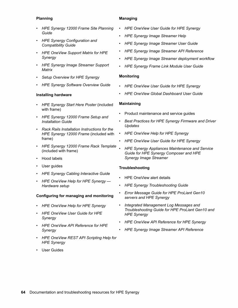
Planning
• HPE Synergy 12000 Frame Site PlanningGuide
• HPE Synergy Configuration andCompatibility Guide
• HPE OneView Support Matrix for HPESynergy
• HPE Synergy Image Streamer SupportMatrix
• Setup Overview for HPE Synergy
• HPE Synergy Software Overview Guide
Installing hardware
• HPE Synergy Start Here Poster (includedwith frame)
• HPE Synergy 12000 Frame Setup andInstallation Guide
• Rack Rails Installation Instructions for theHPE Synergy 12000 Frame (included withframe)
• HPE Synergy 12000 Frame Rack Template(included with frame)
• Hood labels
• User guides
• HPE Synergy Cabling Interactive Guide
• HPE OneView Help for HPE Synergy —Hardware setup
Configuring for managing and monitoring
• HPE OneView Help for HPE Synergy
• HPE OneView User Guide for HPESynergy
• HPE OneView API Reference for HPESynergy
• HPE OneView REST API Scripting Help forHPE Synergy
• User Guides
Managing
• HPE OneView User Guide for HPE Synergy
• HPE Synergy Image Streamer Help
• HPE Synergy Image Streamer User Guide
• HPE Synergy Image Streamer API Reference
• HPE Synergy Image Streamer deployment workflow
• HPE Synergy Frame Link Module User Guide
Monitoring
• HPE OneView User Guide for HPE Synergy
• HPE OneView Global Dashboard User Guide
Maintaining
• Product maintenance and service guides
• Best Practices for HPE Synergy Firmware and DriverUpdates
• HPE OneView Help for HPE Synergy
• HPE OneView User Guide for HPE Synergy
• HPE Synergy Appliances Maintenance and ServiceGuide for HPE Synergy Composer and HPESynergy Image Streamer
Troubleshooting
• HPE OneView alert details
• HPE Synergy Troubleshooting Guide
• Error Message Guide for HPE ProLiant Gen10servers and HPE Synergy
• Integrated Management Log Messages andTroubleshooting Guide for HPE ProLiant Gen10 andHPE Synergy
• HPE OneView API Reference for HPE Synergy
• HPE Synergy Image Streamer API Reference
64 Documentation and troubleshooting resources for HPE Synergy
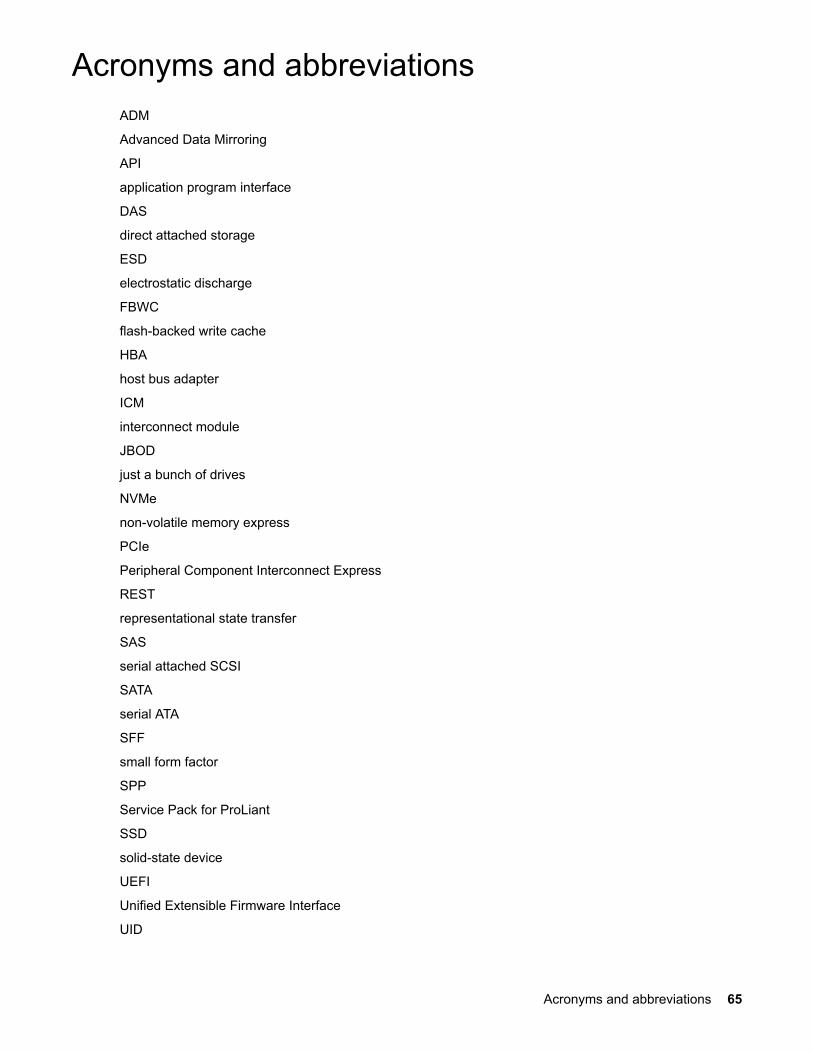
Acronyms and abbreviationsADM
Advanced Data Mirroring
API
application program interface
DAS
direct attached storage
ESD
electrostatic discharge
FBWC
flash-backed write cache
HBA
host bus adapter
ICM
interconnect module
JBOD
just a bunch of drives
NVMe
non-volatile memory express
PCIe
Peripheral Component Interconnect Express
REST
representational state transfer
SAS
serial attached SCSI
SATA
serial ATA
SFF
small form factor
SPP
Service Pack for ProLiant
SSD
solid-state device
UEFI
Unified Extensible Firmware Interface
UID
Acronyms and abbreviations 65
unit identification
VRM
voltage regulator module
VSA
virtual storage appliance
66 Acronyms and abbreviations
Support and other resources
Accessing Hewlett Packard Enterprise Support• For live assistance, go to the Contact Hewlett Packard Enterprise Worldwide website:
http://www.hpe.com/assistance
• To access documentation and support services, go to the Hewlett Packard Enterprise Support Centerwebsite:
http://www.hpe.com/support/hpesc
Information to collect
• Technical support registration number (if applicable)
• Product name, model or version, and serial number
• Operating system name and version
• Firmware version
• Error messages
• Product-specific reports and logs
• Add-on products or components
• Third-party products or components
Accessing updates• Some software products provide a mechanism for accessing software updates through the product
interface. Review your product documentation to identify the recommended software update method.
• To download product updates:
Hewlett Packard Enterprise Support Centerwww.hpe.com/support/hpesc
Hewlett Packard Enterprise Support Center: Software downloadswww.hpe.com/support/downloads
Software Depotwww.hpe.com/support/softwaredepot
• To subscribe to eNewsletters and alerts:
www.hpe.com/support/e-updates
• To view and update your entitlements, and to link your contracts and warranties with your profile, go tothe Hewlett Packard Enterprise Support Center More Information on Access to Support Materialspage:
Support and other resources 67
www.hpe.com/support/AccessToSupportMaterials
IMPORTANT:
Access to some updates might require product entitlement when accessed through the HewlettPackard Enterprise Support Center. You must have an HPE Passport set up with relevantentitlements.
Customer self repairHewlett Packard Enterprise customer self repair (CSR) programs allow you to repair your product. If aCSR part needs to be replaced, it will be shipped directly to you so that you can install it at yourconvenience. Some parts do not qualify for CSR. Your Hewlett Packard Enterprise authorized serviceprovider will determine whether a repair can be accomplished by CSR.
For more information about CSR, contact your local service provider or go to the CSR website:
http://www.hpe.com/support/selfrepair
Remote supportRemote support is available with supported devices as part of your warranty or contractual supportagreement. It provides intelligent event diagnosis, and automatic, secure submission of hardware eventnotifications to Hewlett Packard Enterprise, which will initiate a fast and accurate resolution based on yourproduct's service level. Hewlett Packard Enterprise strongly recommends that you register your device forremote support.
If your product includes additional remote support details, use search to locate that information.
Remote support and Proactive Care informationHPE Get Connected
www.hpe.com/services/getconnectedHPE Proactive Care services
www.hpe.com/services/proactivecareHPE Proactive Care service: Supported products list
www.hpe.com/services/proactivecaresupportedproductsHPE Proactive Care advanced service: Supported products list
www.hpe.com/services/proactivecareadvancedsupportedproducts
Proactive Care customer informationProactive Care central
www.hpe.com/services/proactivecarecentralProactive Care service activation
www.hpe.com/services/proactivecarecentralgetstarted
Warranty informationTo view the warranty for your product or to view the Safety and Compliance Information for Server,Storage, Power, Networking, and Rack Products reference document, go to the Enterprise Safety andCompliance website:
www.hpe.com/support/Safety-Compliance-EnterpriseProducts
68 Customer self repair
Additional warranty informationHPE ProLiant and x86 Servers and Options
www.hpe.com/support/ProLiantServers-WarrantiesHPE Enterprise Servers
www.hpe.com/support/EnterpriseServers-WarrantiesHPE Storage Products
www.hpe.com/support/Storage-WarrantiesHPE Networking Products
www.hpe.com/support/Networking-Warranties
Regulatory informationTo view the regulatory information for your product, view the Safety and Compliance Information forServer, Storage, Power, Networking, and Rack Products, available at the Hewlett Packard EnterpriseSupport Center:
www.hpe.com/support/Safety-Compliance-EnterpriseProducts
Additional regulatory information
Hewlett Packard Enterprise is committed to providing our customers with information about the chemicalsubstances in our products as needed to comply with legal requirements such as REACH (Regulation ECNo 1907/2006 of the European Parliament and the Council). A chemical information report for this productcan be found at:
www.hpe.com/info/reach
For Hewlett Packard Enterprise product environmental and safety information and compliance data,including RoHS and REACH, see:
www.hpe.com/info/ecodata
For Hewlett Packard Enterprise environmental information, including company programs, productrecycling, and energy efficiency, see:
www.hpe.com/info/environment
Documentation feedbackHewlett Packard Enterprise is committed to providing documentation that meets your needs. To help usimprove the documentation, send any errors, suggestions, or comments to Documentation Feedback([email protected]). When submitting your feedback, include the document title, part number,edition, and publication date located on the front cover of the document. For online help content, includethe product name, product version, help edition, and publication date located on the legal notices page.
Regulatory information 69