Embed Size (px)
Citation preview
HPE Synergy 12000 Frame Maintenance andService Guide
Part Number: 806423-004Published: August 2019Edition: 4
Abstract
This guide is for an experienced service technician. Hewlett Packard Enterprise assumes you are qualified in theservicing of computer equipment and trained in recognizing hazards in products with hazardous energy levelsand are familiar with weight and stability precautions for rack installations.

© Copyright 2016-2019 Hewlett Packard Enterprise Development LP
Notices
The information contained herein is subject to change without notice. The only warranties for Hewlett Packard Enterpriseproducts and services are set forth in the express warranty statements accompanying such products and services. Nothingherein should be construed as constituting an additional warranty. Hewlett Packard Enterprise shall not be liable for technicalor editorial errors or omissions contained herein.
Confidential computer software. Valid license from Hewlett Packard Enterprise required for possession, use, or copying.Consistent with FAR 12.211 and 12.212, Commercial Computer Software, Computer Software Documentation, and TechnicalData for Commercial Items are licensed to the U.S. Government under vendor's standard commercial license.
Links to third-party websites take you outside the Hewlett Packard Enterprise website. Hewlett Packard Enterprise has nocontrol over and is not responsible for information outside the Hewlett Packard Enterprise website.
Contents
Illustrated parts catalog.........................................................................................................6Mechanical components.........................................................................................................................................................................................................6
Power supply blank spare part......................................................................................................................................................................... 7Interconnect module blank spare part......................................................................................................................................................... 7Device bay blank spare part...............................................................................................................................................................................7Frame link module blank spare part.............................................................................................................................................................. 7Rack rail kit spare part........................................................................................................................................................................................... 7Bezel assembly spare part...................................................................................................................................................................................7Frame lift handles spare part.............................................................................................................................................................................7Device bay shelf spare part.................................................................................................................................................................................7Device bay half shelf spare part.......................................................................................................................................................................8Appliance bay blank spare part........................................................................................................................................................................8
System components..................................................................................................................................................................................................................8Hot-plug fan spare part........................................................................................................................................................................................ 9Power supply spare part.......................................................................................................................................................................................9Front panel assembly spare part..................................................................................................................................................................... 9Fan interposer assembly spare part.............................................................................................................................................................. 9Frame link module spare part............................................................................................................................................................................9Midplane assembly spare part....................................................................................................................................................................... 10Appliance module spare part..........................................................................................................................................................................10Interconnect module spare part....................................................................................................................................................................10
Cables and miscellaneous components......................................................................................................................................................................11Frame cabling spare part...................................................................................................................................................................................11Networking cable spare parts.........................................................................................................................................................................11Transceiver spare parts..................................................................................................................................................................................... 14
Customer self repair............................................................................................................. 16
Removal and replacement procedures..............................................................................25Required tools........................................................................................................................................................................................................................... 25Appliance module support and documentation....................................................................................................................................................25Safety considerations............................................................................................................................................................................................................25
Electrostatic discharge....................................................................................................................................................................................... 25Warnings, cautions, and important messages.......................................................................................................................................26
Preparing the frame ..............................................................................................................................................................................................................26Locating the frame in the rack.......................................................................................................................................................................27Powering down the compute module .......................................................................................................................................................27Powering down the storage module ..........................................................................................................................................................28Powering down the appliance module...................................................................................................................................................... 28Powering down the frame ............................................................................................................................................................................... 28HPE Synergy Console connections............................................................................................................................................................. 29
Removing and replacing bezels...................................................................................................................................................................................... 32Removing and replacing a device bay blank...........................................................................................................................................................33Removing and replacing a device bay shelf.............................................................................................................................................................34Removing the half shelf.......................................................................................................................................................................................................35
Replacing the half shelf......................................................................................................................................................................................35Replacing the half shelf........................................................................................................................................................................................................36Removing and replacing an appliance bay blank................................................................................................................................................. 37
3
Removing and replacing hot-plug fans...................................................................................................................................................................... 38Removing and replacing a frame lift handle............................................................................................................................................................39Removing and replacing a frame link module blank...........................................................................................................................................39Removing and replacing a frame link module........................................................................................................................................................ 40Removing and replacing a front panel assembly..................................................................................................................................................41Removing and replacing an interconnect module blank..................................................................................................................................41Removing and replacing an interconnect module................................................................................................................................................42Removing and replacing a power supply blank.....................................................................................................................................................42Removing and replacing a power supply.................................................................................................................................................................. 43Removing and replacing a –48V DC power supply.............................................................................................................................................44
Replacing the –48V DC power supply.......................................................................................................................................................46Removing and replacing a rear cage............................................................................................................................................................................48Removing and replacing the rack rails........................................................................................................................................................................49
Replacing the rack rails...................................................................................................................................................................................... 50
Component and LED identification....................................................................................52Information pull tabs............................................................................................................................................................................................................. 52
Mobile-ready content.......................................................................................................................................................................................... 53Mobile QR code locations..................................................................................................................................................................................53
Frame front components and device bays............................................................................................................................................................... 53Device bay numbering........................................................................................................................................................................................ 54Front panel components....................................................................................................................................................................................56Appliance module LEDs and components.............................................................................................................................................. 57Compute module LEDs and buttons.......................................................................................................................................................... 60Storage module LEDs..........................................................................................................................................................................................62
Frame rear components.......................................................................................................................................................................................................63Rear component bay numbering.................................................................................................................................................................. 64HPE Synergy 4-Port Frame Link Module components and LEDs.............................................................................................65HPE Synergy Frame Link Module components and LEDs.............................................................................................................68Power supply LED................................................................................................................................................................................................. 70Fan LED....................................................................................................................................................................................................................... 70HPE Synergy 10Gb Interconnect Link Module LEDs and buttons...........................................................................................71HPE Synergy 10Gb Interconnect Module interconnect link port..............................................................................................71HPE Synergy 20Gb Interconnect Link Module LEDs and buttons...........................................................................................72HPE Synergy 20Gb Interconnect Link Module interconnect link ports.................................................................................73HPE Synergy 50Gb Interconnect Link Module LEDs and buttons...........................................................................................73HPE Synergy 50Gb Interconnect Link Module interconnect link ports.................................................................................74HPE Virtual Connect SE 100Gb F8 Module for HPE Synergy LEDs and buttons...........................................................74HPE Virtual Connect SE 100Gb F32 Module for HPE Synergy components.....................................................................78HPE Virtual Connect SE 40Gb F8 Module for HPE Synergy LEDs and buttons..............................................................78HPE Virtual Connect SE 40Gb F8 Module for HPE Synergy components...........................................................................80HPE Synergy 40Gb F8 Switch Module LEDs and buttons............................................................................................................ 81HPE Synergy 40Gb F8 Switch Module components.........................................................................................................................83Mellanox SH2200 Switch Module for HPE Synergy LEDs and components......................................................................84
HPE Synergy Cabling............................................................................................................85
HPE Synergy documentation resources........................................................................... 86HPE Synergy firmware update resources.................................................................................................................................................................87
HPE Synergy document overview (documentation map)............................................. 89
4
Specifications.........................................................................................................................90HPE Synergy QuickSpecs................................................................................................................................................................................................... 90
Websites................................................................................................................................. 91
Support and other resources.............................................................................................. 92Accessing Hewlett Packard Enterprise Support................................................................................................................................................... 92Accessing updates..................................................................................................................................................................................................................92Customer self repair...............................................................................................................................................................................................................93Remote support........................................................................................................................................................................................................................93Warranty information............................................................................................................................................................................................................93Regulatory information........................................................................................................................................................................................................93Documentation feedback....................................................................................................................................................................................................94
5
Illustrated parts catalog
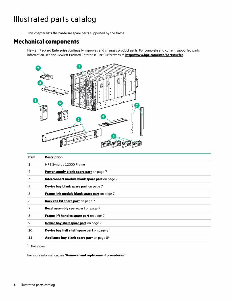
This chapter lists the hardware spare parts supported by the frame.
Mechanical componentsHewlett Packard Enterprise continually improves and changes product parts. For complete and current supported partsinformation, see the Hewlett Packard Enterprise PartSurfer website http://www.hpe.com/info/partssurfer.
Item Description
1 HPE Synergy 12000 Frame
2 Power supply blank spare part on page 7
3 Interconnect module blank spare part on page 7
4 Device bay blank spare part on page 7
5 Frame link module blank spare part on page 7
6 Rack rail kit spare part on page 7
7 Bezel assembly spare part on page 7
8 Frame lift handles spare part on page 7
9 Device bay shelf spare part on page 7
10 Device bay half shelf spare part on page 81
11 Appliance bay blank spare part on page 81
1 Not shown
For more information, see "Removal and replacement procedures."
6 Illustrated parts catalog
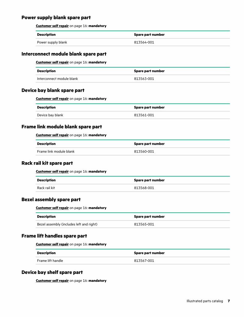
Power supply blank spare partCustomer self repair on page 16: mandatory
Description Spare part number
Power supply blank 813564-001
Interconnect module blank spare partCustomer self repair on page 16: mandatory
Description Spare part number
Interconnect module blank 813563-001
Device bay blank spare partCustomer self repair on page 16: mandatory
Description Spare part number
Device bay blank 813561-001
Frame link module blank spare partCustomer self repair on page 16: mandatory
Description Spare part number
Frame link module blank 813560-001
Rack rail kit spare partCustomer self repair on page 16: mandatory
Description Spare part number
Rack rail kit 813568-001
Bezel assembly spare partCustomer self repair on page 16: mandatory
Description Spare part number
Bezel assembly (includes left and right) 813565-001
Frame lift handles spare partCustomer self repair on page 16: mandatory
Description Spare part number
Frame lift handle 813567-001
Device bay shelf spare partCustomer self repair on page 16: mandatory
Illustrated parts catalog 7
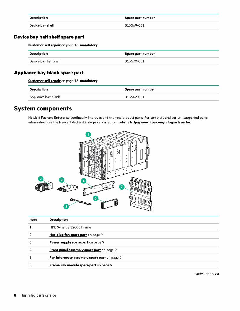
Description Spare part number
Device bay shelf 813569-001
Device bay half shelf spare partCustomer self repair on page 16: mandatory
Description Spare part number
Device bay half shelf 813570-001
Appliance bay blank spare partCustomer self repair on page 16: mandatory
Description Spare part number
Appliance bay blank 813562-001
System componentsHewlett Packard Enterprise continually improves and changes product parts. For complete and current supported partsinformation, see the Hewlett Packard Enterprise PartSurfer website http://www.hpe.com/info/partssurfer.
Item Description
1 HPE Synergy 12000 Frame
2 Hot-plug fan spare part on page 9
3 Power supply spare part on page 9
4 Front panel assembly spare part on page 9
5 Fan interposer assembly spare part on page 9
6 Frame link module spare part on page 9
Table Continued
8 Illustrated parts catalog

Item Description
7 Midplane assembly spare part on page 10
8 Appliance module spare part on page 101
9 Interconnect module spare part on page 10 1
1 Not shown
For more information, see "Removal and replacement procedures."
Hot-plug fan spare partCustomer self repair on page 16: mandatory
Description Spare part number
Hot-plug fan 807967-001
Power supply spare partCustomer self repair on page 16: mandatory
Description Spare part number
2900-3400W, hot plug, Platinum 882168-001
2650W, performance hot plug, Titanium Plus 813829-001
2650W, HV DC, hot plug 813833-001
2650W, 277V AC, hot plug 813832-001
2650W, -48V DC, hot plug (with lugs, screws, washers, nuts for cabletermination)
813831-001
Front panel assembly spare partCustomer self repair on page 16: mandatory
Description Spare part number
Front panel assembly 807965-001
Fan interposer assembly spare partCustomer self repair on page 16: no
Description Spare part number
Fan interposer assembly 807966-001
Frame link module spare partCustomer self repair on page 16: mandatory
Illustrated parts catalog 9
Description Spare part number
HPE Synergy Frame Link Module (2-port) 807963-001
HPE Synergy 4-Port Frame Link Module P04749-001
Midplane assembly spare partCustomer self repair on page 16: no
Description Spare part number
Midplane assembly 869597-002
Appliance module spare partThe appliance module removal and replacement procedures are available in the HPE Synergy Appliance Maintenance andService Guide on the Hewlett Packard Enterprise website.
Interconnect module spare partCustomer self repair on page 16: mandatory
Virtual Connect master and satellite modules
Description Spare part number
HPE Virtual Connect SE 100Gb F32 Module for HPE Synergy 879438-001
HPE Synergy 50Gb Interconnect Link Module 879437-001
HPE Virtual Connect SE 40Gb F8 Module for HPE Synergy 813174-001
HPE Synergy 10Gb Interconnect Link Module 785340-001
HPE Synergy 20Gb Interconnect Link Module 785341-001
Fibre Channel modules
Description Spare part number
HPE Virtual Connect SE 32Gb FC Module for HPE Synergy 881769-001
Brocade 32Gb FC Fibre Channel Switch Module 881769-001
HPE Virtual Connect SE 16Gb Fibre Channel Module for HPE Synergy 785338-001
Brocade 16Gb/12 Fibre Channel SAN Switch for HPE Synergy 815264-001
Brocade 16Gb/24 Fibre Channel SAN Switch for HPE Synergy 815265-001
Brocade 16Gb Fibre Channel PowerPack+ Fibre Channel SAN Switch Module for HPESynergy
815267-001
10 Illustrated parts catalog
Ethernet modules
Description Spare part number
HPE Synergy 40Gb F8 Switch Module 785339-001
HPE Synergy 10/40Gb Pass-Thru Module 826019-001
Mellanox SH2200 Switch Module for HPE Synergy 869162-001
Storage modules
Description Spare part number
HPE Synergy 12Gb SAS Connection Module 758686-001
Cables and miscellaneous componentsHewlett Packard Enterprise continually improves and changes product parts. For complete and current supported partsinformation, see the Hewlett Packard Enterprise PartSurfer website http://www.hpe.com/info/partssurfer.
Spare parts are also available for miscellaneous cables and transceivers.
For more information, see "HPE Synergy Cabling."
Frame cabling spare partCustomer self repair on page 16: mandatory
Description Spare part number
HPE Synergy 4p Frame Link Module USB Adapter (for HPESynergy 4-Port Frame Link Module)
P06996-001
Networking cable spare partsCustomer self repair on page 16: mandatory
Direct Attach Cables (DAC)
Description Spare part number
HPE Synergy 300Gb Interconnect Link Direct Attach Cable,2.10 m (82.68 in)
P00410-001
HPE Synergy Interconnect Link Direct Attach Cable, 1.10 m(43.31 in)
818143-001
HPE Synergy Interconnect Link Direct Attach Cable, 1.60 m(62.99 in)
818144-001
HPE Synergy Interconnect Link Direct Attach Cable, 2.10 m(82.68 in)
818142-001
10G SFP+ DAC, 5.00 m (196.85 in) 538300-001
X240 40G QSFP+ DAC, 1.00 m (39.37 in) JG326-61001
X240 40G QSFP+ DAC, 3.00 m (118.11 in) JG327-61001
X240 40G QSFP+ DAC, 5.00 m (196.85 in) JG328-61001
Table Continued
Illustrated parts catalog 11
Description Spare part number
X240 10G SFP+ DAC, 3.00 m (118.11 in) JD097-61301
X240 10G SFP+ DAC, 5.00 m (196.85 in) JG081-61301
X240 QSFP+ 4x10G SFP+ DAC, 1.00 m (39.37 in) JG329-61001
X240 QSFP+ 4x10G SFP+ DAC, 3.00 m (118.11 in) JG330-61001
X240 QSFP+ 4x10G SFP+ DAC, 5.00 m (196.85 in) JG331-61001
10G SFP+ DAC, 0.50 m (19.69 in) 487967-001
10G SFP+ DAC, 1.00 m (39.37 in) 487968-001
10G SFP+ DAC, 3.00 m (118.11 in) 487969-001
X242 10G + to SFP+ DAC, 3.00 m (118.11 in) J9283-61201
40G QSFP+ DAC, 1.00 m (39.37 in) 746963-001
40G QSFP+ DAC, 3.00 m (118.11 in) 746964-001
40G QSFP+ DAC, 5.00 m (196.85 in) 746965-001
40G QSFP+ 4x10G SFP+ DAC, 3.00 m (118.11 in) 746970-001
40G QSFP+ 4x10G SFP+ DAC, 5.00 m (196.85 in) 746971-001
40G QSFP+ DAC, 0.35 m (13.78 in) 746969-001
HPE 100Gb QSFP28 to QSFP28 DAC, 3.00 m (118.11 in) 850393-001
Active Optical Cables (AOC)
Description Spare part number
HPE Synergy 300 Gb Interconnect Link AOC, 3.00 m (118.11in)
P00404-001
HPE Synergy 300 Gb Interconnect Link AOC, 5.00 m (196.85in)
P00405-001
HPE Synergy 300 Gb Interconnect Link AOC, 15.00 m(590.55 in)
P00407-001
HPE Synergy Interconnect Link AOC, 3.00 m (118.11 in) 818138-001
HPE Synergy Interconnect Link AOC, 5.00 m (196.85 in) 818139-001
HPE Synergy Interconnect Link AOC, 10.00 m (393.70 in) 818140-001
HPE Synergy Interconnect Link AOC, 15.00 m (590.55 in) 818141-001
40G QSFP+ AOC, 7.00 m (275.59 in) 746966-001
40G QSFP+ AOC, 10.00 m (393.70 in) 746967-001
40G QSFP+ AOC, 15.00 m (590.55 in) 746968-001
QSFP+ to 4x10G SFP+ AOC optical cable assembly, 7.00 m(275.59 in)
746972-001
QSFP+ to 4x10G SFP+ AOC optical cable assembly, 10.00 m(393.70 in)
746973-001
Table Continued
12 Illustrated parts catalog
Description Spare part number
QSFP+ to 4x10G SFP+ AOC optical cable assembly, 15.00 m(590.55 in)
746974-001
HPE 100Gb QSFP28 to QSFP28 AOC, 15.00 m (590.55 in) 849437-001
HPE 100Gb QSFP28 to QSFP28 AOC, 7.00 m (275.59 in) 850395-001
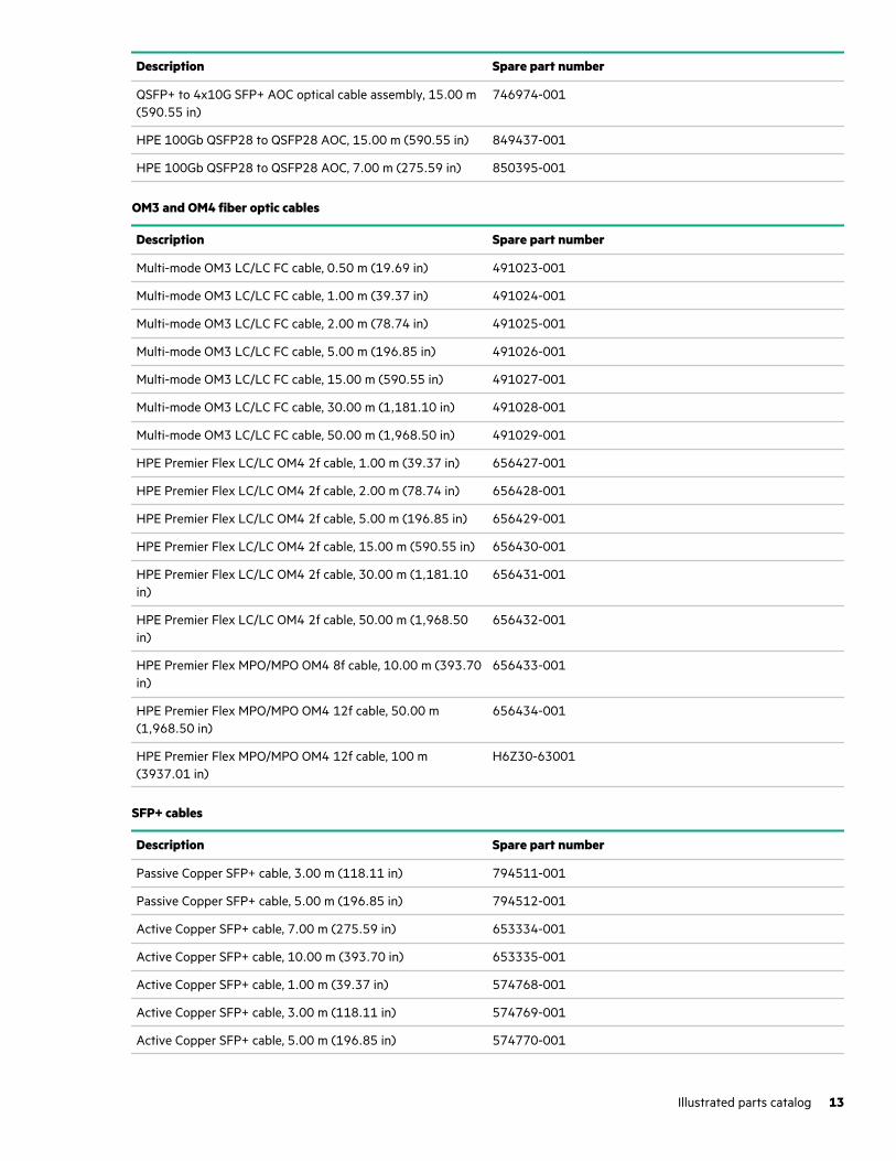
OM3 and OM4 fiber optic cables
Description Spare part number
Multi-mode OM3 LC/LC FC cable, 0.50 m (19.69 in) 491023-001
Multi-mode OM3 LC/LC FC cable, 1.00 m (39.37 in) 491024-001
Multi-mode OM3 LC/LC FC cable, 2.00 m (78.74 in) 491025-001
Multi-mode OM3 LC/LC FC cable, 5.00 m (196.85 in) 491026-001
Multi-mode OM3 LC/LC FC cable, 15.00 m (590.55 in) 491027-001
Multi-mode OM3 LC/LC FC cable, 30.00 m (1,181.10 in) 491028-001
Multi-mode OM3 LC/LC FC cable, 50.00 m (1,968.50 in) 491029-001
HPE Premier Flex LC/LC OM4 2f cable, 1.00 m (39.37 in) 656427-001
HPE Premier Flex LC/LC OM4 2f cable, 2.00 m (78.74 in) 656428-001
HPE Premier Flex LC/LC OM4 2f cable, 5.00 m (196.85 in) 656429-001
HPE Premier Flex LC/LC OM4 2f cable, 15.00 m (590.55 in) 656430-001
HPE Premier Flex LC/LC OM4 2f cable, 30.00 m (1,181.10in)
656431-001
HPE Premier Flex LC/LC OM4 2f cable, 50.00 m (1,968.50in)
656432-001
HPE Premier Flex MPO/MPO OM4 8f cable, 10.00 m (393.70in)
656433-001
HPE Premier Flex MPO/MPO OM4 12f cable, 50.00 m(1,968.50 in)
656434-001
HPE Premier Flex MPO/MPO OM4 12f cable, 100 m(3937.01 in)
H6Z30-63001
SFP+ cables
Description Spare part number
Passive Copper SFP+ cable, 3.00 m (118.11 in) 794511-001
Passive Copper SFP+ cable, 5.00 m (196.85 in) 794512-001
Active Copper SFP+ cable, 7.00 m (275.59 in) 653334-001
Active Copper SFP+ cable, 10.00 m (393.70 in) 653335-001
Active Copper SFP+ cable, 1.00 m (39.37 in) 574768-001
Active Copper SFP+ cable, 3.00 m (118.11 in) 574769-001
Active Copper SFP+ cable, 5.00 m (196.85 in) 574770-001
Illustrated parts catalog 13
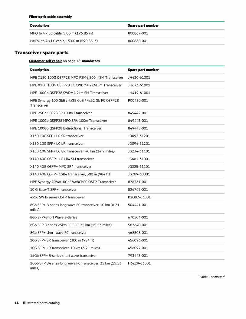
Fiber optic cable assembly
Description Spare part number
MPO to 4 x LC cable, 5.00 m (196.85 in) 800867-001
HMPO to 4 x LC cable, 15.00 m (590.55 in) 800868-001
Transceiver spare partsCustomer self repair on page 16: mandatory
Description Spare part number
HPE X150 100G QSFP28 MPO PSM4 500m SM Transceiver JH420-61001
HPE X150 100G QSFP28 LC CWDM4 2KM SM Transceiver JH673-61001
HPE 100Gb QSFP28 SWDM4 2km SM Transceiver JH419-61001
HPE Synergy 100 GbE / 4x25 GbE / 4x32 Gb FC QSFP28Transceiver
P00430-001
HPE 25Gb SFP28 SR 100m Transceiver 849442-001
HPE 100Gb QSFP28 MPO SR4 100m Transceiver 849443-001
HPE 100Gb QSFP28 Bidirectional Transceiver 849445-001
X130 10G SFP+ LC SR transceiver JD092-61201
X130 10G SFP+ LC LR transceiver JD094-61201
X130 10G SFP+ LC ER transceiver, 40 km (24.9 miles) JG234-61101
X140 40G QSFP+ LC LR4 SM transceiver JG661-61001
X140 40G QSFP+ MPO SR4 transceiver JG325-61101
X140 40G QSFP+ CSR4 transceiver, 300 m (984 ft) JG709-60001
HPE Synergy 40/4x10GbE/4x8GbFC QSFP Transceiver 826761-001
10 G Base-T SFP+ transceiver 826762-001
4x16 SW B-series QSFP transceiver K2Q87-63001
8Gb SFP+ B-series long wave FC transceiver, 10 km (6.21miles)
504441-001
8Gb SFP+Short Wave B-Series 670504-001
8Gb SFP B-series 25km FC SFP, 25 km (15.53 miles) 582640-001
8Gb SFP+ short wave FC transceiver 468508-001
10G SFP+ SR transceiver (300 m (984 ft) 456096-001
10G SFP+ LR transceiver, 10 km (6.21 miles) 456097-001
16Gb SFP+ B-series short wave transceiver 793443-001
16Gb SFP B-series long wave FC transceiver, 25 km (15.53miles)
H6Z29-63001
Table Continued
14 Illustrated parts catalog
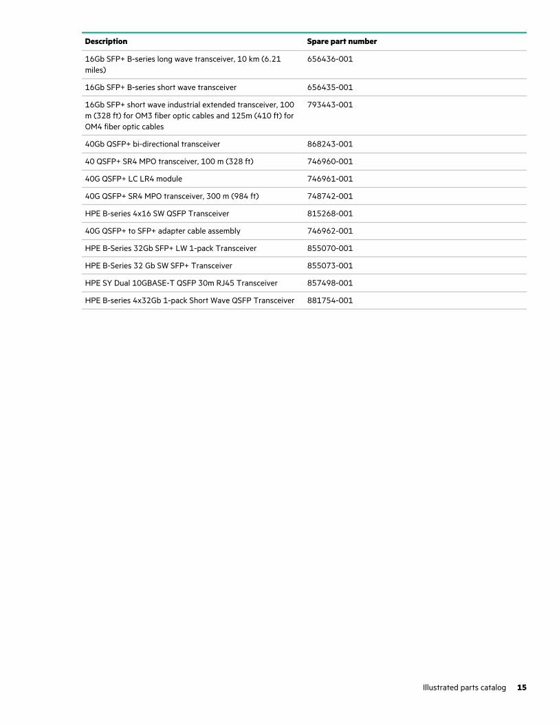
Description Spare part number
16Gb SFP+ B-series long wave transceiver, 10 km (6.21miles)
656436-001
16Gb SFP+ B-series short wave transceiver 656435-001
16Gb SFP+ short wave industrial extended transceiver, 100m (328 ft) for OM3 fiber optic cables and 125m (410 ft) forOM4 fiber optic cables
793443-001
40Gb QSFP+ bi-directional transceiver 868243-001
40 QSFP+ SR4 MPO transceiver, 100 m (328 ft) 746960-001
40G QSFP+ LC LR4 module 746961-001
40G QSFP+ SR4 MPO transceiver, 300 m (984 ft) 748742-001
HPE B-series 4x16 SW QSFP Transceiver 815268-001
40G QSFP+ to SFP+ adapter cable assembly 746962-001
HPE B-Series 32Gb SFP+ LW 1-pack Transceiver 855070-001
HPE B-Series 32 Gb SW SFP+ Transceiver 855073-001
HPE SY Dual 10GBASE-T QSFP 30m RJ45 Transceiver 857498-001
HPE B-series 4x32Gb 1-pack Short Wave QSFP Transceiver 881754-001
Illustrated parts catalog 15
Customer self repair
Hewlett Packard Enterprise products are designed with many Customer Self Repair (CSR) parts to minimize repair time andallow for greater flexibility in performing defective parts replacement. If during the diagnosis period Hewlett PackardEnterprise (or Hewlett Packard Enterprise service providers or service partners) identifies that the repair can be accomplishedby the use of a CSR part, Hewlett Packard Enterprise will ship that part directly to you for replacement. There are twocategories of CSR parts:
• Mandatory—Parts for which customer self repair is mandatory. If you request Hewlett Packard Enterprise to replace theseparts, you will be charged for the travel and labor costs of this service.
• Optional—Parts for which customer self repair is optional. These parts are also designed for customer self repair. If,however, you require that Hewlett Packard Enterprise replace them for you, there may or may not be additional charges,depending on the type of warranty service designated for your product.
NOTE: Some Hewlett Packard Enterprise parts are not designed for customer self repair. In order to satisfy the customerwarranty, Hewlett Packard Enterprise requires that an authorized service provider replace the part. These parts are identifiedas "No" in the Illustrated Parts Catalog.
Based on availability and where geography permits, CSR parts will be shipped for next business day delivery. Same day or four-hour delivery may be offered at an additional charge where geography permits. If assistance is required, you can call theHewlett Packard Enterprise Support Center and a technician will help you over the telephone. Hewlett Packard Enterprisespecifies in the materials shipped with a replacement CSR part whether a defective part must be returned to Hewlett PackardEnterprise. In cases where it is required to return the defective part to Hewlett Packard Enterprise, you must ship the defectivepart back to Hewlett Packard Enterprise within a defined period of time, normally five (5) business days. The defective partmust be returned with the associated documentation in the provided shipping material. Failure to return the defective partmay result in Hewlett Packard Enterprise billing you for the replacement. With a customer self repair, Hewlett PackardEnterprise will pay all shipping and part return costs and determine the courier/carrier to be used.
For more information about the Hewlett Packard Enterprise CSR program, contact your local service provider. For the NorthAmerican program, go to the Hewlett Packard Enterprise CSR website.
Parts only warranty service
Your Hewlett Packard Enterprise Limited Warranty may include a parts only warranty service. Under the terms of parts onlywarranty service, Hewlett Packard Enterprise will provide replacement parts free of charge.
For parts only warranty service, CSR part replacement is mandatory. If you request Hewlett Packard Enterprise to replacethese parts, you will be charged for the travel and labor costs of this service.
Réparation par le client (CSR)
Les produits Hewlett Packard Enterprise comportent de nombreuses pièces CSR (Customer Self Repair = réparation par leclient) afin de minimiser les délais de réparation et faciliter le remplacement des pièces défectueuses. Si pendant la période dediagnostic, Hewlett Packard Enterprise (ou ses partenaires ou mainteneurs agréés) détermine que la réparation peut êtreeffectuée à l'aide d'une pièce CSR, Hewlett Packard Enterprise vous l'envoie directement. Il existe deux catégories de piècesCSR :
• Obligatoire—Pièces pour lesquelles la réparation par le client est obligatoire. Si vous demandez à Hewlett PackardEnterprise de remplacer ces pièces, les coûts de déplacement et main d'œuvre du service vous seront facturés.
• Facultatif—Pièces pour lesquelles la réparation par le client est facultative. Ces pièces sont également conçues pourpermettre au client d'effectuer lui-même la réparation. Toutefois, si vous demandez à Hewlett Packard Enterprise deremplacer ces pièces, l'intervention peut ou non vous être facturée, selon le type de garantie applicable à votre produit.
16 Customer self repair
REMARQUE: Certaines pièces Hewlett Packard Enterprise ne sont pas conçues pour permettre au client d'effectuer lui-mêmela réparation. Pour que la garantie puisse s'appliquer, Hewlett Packard Enterprise exige que le remplacement de la pièce soiteffectué par un Mainteneur Agréé. Ces pièces sont identifiées par la mention "Non" dans le Catalogue illustré.
Les pièces CSR sont livrées le jour ouvré suivant, dans la limite des stocks disponibles et selon votre situation géographique. Sivotre situation géographique le permet et que vous demandez une livraison le jour même ou dans les 4 heures, celle-ci voussera facturée. Pour toute assistance, appelez le Centre d’assistance Hewlett Packard Enterprise pour qu’un technicien vousaide au téléphone Dans les documents envoyés avec la pièce de rechange CSR, Hewlett Packard Enterprise précise s'il estnécessaire de lui retourner la pièce défectueuse. Si c'est le cas, vous devez le faire dans le délai indiqué, généralement cinq (5)jours ouvrés. La pièce et sa documentation doivent être retournées dans l'emballage fourni. Si vous ne retournez pas la piècedéfectueuse, Hewlett Packard Enterprise se réserve le droit de vous facturer les coûts de remplacement. Dans le cas d'unepièce CSR, Hewlett Packard Enterprise supporte l'ensemble des frais d'expédition et de retour, et détermine la société decourses ou le transporteur à utiliser.
Pour plus d'informations sur le programme CSR de Hewlett Packard Enterprise, contactez votre Mainteneur Agrée local. Pourplus d'informations sur ce programme en Amérique du Nord, consultez le site Web Hewlett Packard Enterprise.
Service de garantie "pièces seules"
Votre garantie limitée Hewlett Packard Enterprise peut inclure un service de garantie "pièces seules". Dans ce cas, les pièces derechange fournies par Hewlett Packard Enterprise ne sont pas facturées.
Dans le cadre de ce service, la réparation des pièces CSR par le client est obligatoire. Si vous demandez à Hewlett PackardEnterprise de remplacer ces pièces, les coûts de déplacement et main d'œuvre du service vous seront facturés.
Riparazione da parte del cliente
Per abbreviare i tempi di riparazione e garantire una maggiore flessibilità nella sostituzione di parti difettose, i prodotti HewlettPackard Enterprise sono realizzati con numerosi componenti che possono essere riparati direttamente dal cliente (CSR,Customer Self Repair). Se in fase di diagnostica Hewlett Packard Enterprise (o un centro di servizi o di assistenza HewlettPackard Enterprise) identifica il guasto come riparabile mediante un ricambio CSR, Hewlett Packard Enterprise lo spediràdirettamente al cliente per la sostituzione. Vi sono due categorie di parti CSR:
• Obbligatorie—Parti che devono essere necessariamente riparate dal cliente. Se il cliente ne affida la riparazione adHewlett Packard Enterprise, deve sostenere le spese di spedizione e di manodopera per il servizio.
• Opzionali—Parti la cui riparazione da parte del cliente è facoltativa. Si tratta comunque di componenti progettati perquesto scopo. Se tuttavia il cliente ne richiede la sostituzione ad Hewlett Packard Enterprise, potrebbe dover sostenerespese addizionali a seconda del tipo di garanzia previsto per il prodotto.
NOTA: alcuni componenti Hewlett Packard Enterprise non sono progettati per la riparazione da parte del cliente. Per rispettarela garanzia, Hewlett Packard Enterprise richiede che queste parti siano sostituite da un centro di assistenza autorizzato. Taliparti sono identificate da un "No" nel Catalogo illustrato dei componenti.
In base alla disponibilità e alla località geografica, le parti CSR vengono spedite con consegna entro il giorno lavorativoseguente. La consegna nel giorno stesso o entro quattro ore è offerta con un supplemento di costo solo in alcune zone. In casodi necessità si può richiedere l'assistenza telefonica di un addetto del centro di supporto tecnico Hewlett Packard Enterprise.Nel materiale fornito con una parte di ricambio CSR, Hewlett Packard Enterprise specifica se il cliente deve restituire deicomponent. Qualora sia richiesta la resa ad Hewlett Packard Enterprise del componente difettoso, lo si deve spedire ad HewlettPackard Enterprise entro un determinato periodo di tempo, generalmente cinque (5) giorni lavorativi. Il componente difettosodeve essere restituito con la documentazione associata nell'imballo di spedizione fornito. La mancata restituzione delcomponente può comportare la fatturazione del ricambio da parte di Hewlett Packard Enterprise. Nel caso di riparazione daparte del cliente, Hewlett Packard Enterprise sostiene tutte le spese di spedizione e resa e sceglie il corriere/vettore dautilizzare.
Per ulteriori informazioni sul programma CSR di Hewlett Packard Enterprise, contattare il centro di assistenza di zona. Per ilprogramma in Nord America fare riferimento al sito Web.
Customer self repair 17
Servizio di garanzia per i soli componenti
La garanzia limitata Hewlett Packard Enterprise può includere un servizio di garanzia per i soli componenti. Nei termini digaranzia del servizio per i soli componenti, Hewlett Packard Enterprise fornirà gratuitamente le parti di ricambio.
Per il servizio di garanzia per i soli componenti è obbligatoria la formula CSR che prevede la riparazione da parte del cliente. Seil cliente invece richiede la sostituzione ad Hewlett Packard Enterprise dovrà sostenere le spese di spedizione e di manodoperaper il servizio.
Customer Self Repair
Hewlett Packard Enterprise Produkte enthalten viele CSR-Teile (Customer Self Repair), um Reparaturzeiten zu minimieren undhöhere Flexibilität beim Austausch defekter Bauteile zu ermöglichen. Wenn Hewlett Packard Enterprise (oder ein HewlettPackard Enterprise Servicepartner) bei der Diagnose feststellt, dass das Produkt mithilfe eines CSR-Teils repariert werdenkann, sendet Ihnen Hewlett Packard Enterprise dieses Bauteil zum Austausch direkt zu. CSR-Teile werden in zwei Kategorienunterteilt:
• Zwingend—Teile, für die das Customer Self Repair-Verfahren zwingend vorgegeben ist. Wenn Sie den Austausch dieserTeile von Hewlett Packard Enterprise vornehmen lassen, werden Ihnen die Anfahrt- und Arbeitskosten für diesen Serviceberechnet.
• Optional—Teile, für die das Customer Self Repair-Verfahren optional ist. Diese Teile sind auch für Customer Self Repairausgelegt. Wenn Sie jedoch den Austausch dieser Teile von Hewlett Packard Enterprise vornehmen lassen möchten,können bei diesem Service je nach den für Ihr Produkt vorgesehenen Garantiebedingungen zusätzliche Kosten anfallen.
HINWEIS: Einige Hewlett Packard Enterprise Teile sind nicht für Customer Self Repair ausgelegt. Um den Garantieanspruchdes Kunden zu erfüllen, muss das Teil von einem Hewlett Packard Enterprise Servicepartner ersetzt werden. Im illustriertenTeilekatalog sind diese Teile mit „No“ bzw. „Nein“ gekennzeichnet.
CSR-Teile werden abhängig von der Verfügbarkeit und vom Lieferziel am folgenden Geschäftstag geliefert. Für bestimmteStandorte ist eine Lieferung am selben Tag oder innerhalb von vier Stunden gegen einen Aufpreis verfügbar. Wenn Sie Hilfebenötigen, können Sie das Hewlett Packard Enterprise Support Center anrufen und sich von einem Mitarbeiter per Telefonhelfen lassen. Den Materialien von Hewlett Packard Enterprise, die mit einem CSR-Ersatzteil geliefert werden, können Sieentnehmen, ob das defekte Teil an Hewlett Packard Enterprise zurückgeschickt werden muss. Wenn es erforderlich ist, dasdefekte Teil an Hewlett Packard Enterprise zurückzuschicken, müssen Sie dies innerhalb eines vorgegebenen Zeitraums tun, inder Regel innerhalb von fünf (5) Geschäftstagen. Das defekte Teil muss mit der zugehörigen Dokumentation in derVerpackung zurückgeschickt werden, die im Lieferumfang enthalten ist. Wenn Sie das defekte Teil nicht zurückschicken, kannHewlett Packard Enterprise Ihnen das Ersatzteil in Rechnung stellen. Im Falle von Customer Self Repair kommt HewlettPackard Enterprise für alle Kosten für die Lieferung und Rücksendung auf und bestimmt den Kurier-/Frachtdienst.
Weitere Informationen über das Hewlett Packard Enterprise Customer Self Repair Programm erhalten Sie von IhremServicepartner vor Ort. Informationen über das CSR-Programm in Nordamerika finden Sie auf der Hewlett Packard EnterpriseWebsite unter.
Parts-only Warranty Service (Garantieservice ausschließlich für Teile)
Ihre Hewlett Packard Enterprise Garantie umfasst möglicherweise einen Parts-only Warranty Service (Garantieserviceausschließlich für Teile). Gemäß den Bestimmungen des Parts-only Warranty Service stellt Hewlett Packard EnterpriseErsatzteile kostenlos zur Verfügung.
Für den Parts-only Warranty Service ist das CSR-Verfahren zwingend vorgegeben. Wenn Sie den Austausch dieser Teile vonHewlett Packard Enterprise vornehmen lassen, werden Ihnen die Anfahrt- und Arbeitskosten für diesen Service berechnet.
Reparaciones del propio cliente
Los productos de Hewlett Packard Enterprise incluyen muchos componentes que el propio usuario puede reemplazar(Customer Self Repair, CSR) para minimizar el tiempo de reparación y ofrecer una mayor flexibilidad a la hora de realizarsustituciones de componentes defectuosos. Si, durante la fase de diagnóstico, Hewlett Packard Enterprise (o los proveedores osocios de servicio de Hewlett Packard Enterprise) identifica que una reparación puede llevarse a cabo mediante el uso de un
18 Customer self repair
componente CSR, Hewlett Packard Enterprise le enviará dicho componente directamente para que realice su sustitución. Loscomponentes CSR se clasifican en dos categorías:
• Obligatorio—Componentes cuya reparación por parte del usuario es obligatoria. Si solicita a Hewlett Packard Enterpriseque realice la sustitución de estos componentes, tendrá que hacerse cargo de los gastos de desplazamiento y de mano deobra de dicho servicio.
• Opcional—Componentes cuya reparación por parte del usuario es opcional. Estos componentes también están diseñadospara que puedan ser reparados por el usuario. Sin embargo, si precisa que Hewlett Packard Enterprise realice susustitución, puede o no conllevar costes adicionales, dependiendo del tipo de servicio de garantía correspondiente alproducto.
NOTA: Algunos componentes de Hewlett Packard Enterprise no están diseñados para que puedan ser reparados por elusuario. Para que el usuario haga valer su garantía, Hewlett Packard Enterprise pone como condición que un proveedor deservicios autorizado realice la sustitución de estos componentes. Dichos componentes se identifican con la palabra "No" en elcatálogo ilustrado de componentes.
Según la disponibilidad y la situación geográfica, los componentes CSR se enviarán para que lleguen a su destino al siguientedía laborable. Si la situación geográfica lo permite, se puede solicitar la entrega en el mismo día o en cuatro horas con un costeadicional. Si precisa asistencia técnica, puede llamar al Centro de asistencia técnica de Hewlett Packard Enterprise y recibiráayuda telefónica por parte de un técnico. Con el envío de materiales para la sustitución de componentes CSR, Hewlett PackardEnterprise especificará si los componentes defectuosos deberán devolverse a Hewlett Packard Enterprise. En aquellos casos enlos que sea necesario devolver algún componente a Hewlett Packard Enterprise, deberá hacerlo en el periodo de tiempoespecificado, normalmente cinco días laborables. Los componentes defectuosos deberán devolverse con toda ladocumentación relacionada y con el embalaje de envío. Si no enviara el componente defectuoso requerido, Hewlett PackardEnterprise podrá cobrarle por el de sustitución. En el caso de todas sustituciones que lleve a cabo el cliente, Hewlett PackardEnterprise se hará cargo de todos los gastos de envío y devolución de componentes y escogerá la empresa de transporte quese utilice para dicho servicio.
Para obtener más información acerca del programa de Reparaciones del propio cliente de Hewlett Packard Enterprise, póngaseen contacto con su proveedor de servicios local. Si está interesado en el programa para Norteamérica, visite la página web deHewlett Packard Enterprise CSR.
Servicio de garantía exclusivo de componentes
La garantía limitada de Hewlett Packard Enterprise puede que incluya un servicio de garantía exclusivo de componentes.Según las condiciones de este servicio exclusivo de componentes, Hewlett Packard Enterprise le facilitará los componentes derepuesto sin cargo adicional alguno.
Para este servicio de garantía exclusivo de componentes, es obligatoria la sustitución de componentes por parte del usuario(CSR). Si solicita a Hewlett Packard Enterprise que realice la sustitución de estos componentes, tendrá que hacerse cargo delos gastos de desplazamiento y de mano de obra de dicho servicio.
Customer Self Repair
Veel onderdelen in Hewlett Packard Enterprise producten zijn door de klant zelf te repareren, waardoor de reparatieduur toteen minimum beperkt kan blijven en de flexibiliteit in het vervangen van defecte onderdelen groter is. Deze onderdelenworden CSR-onderdelen (Customer Self Repair) genoemd. Als Hewlett Packard Enterprise (of een Hewlett Packard EnterpriseService Partner) bij de diagnose vaststelt dat de reparatie kan worden uitgevoerd met een CSR-onderdeel, verzendt HewlettPackard Enterprise dat onderdeel rechtstreeks naar u, zodat u het defecte onderdeel daarmee kunt vervangen. Er zijn tweecategorieën CSR-onderdelen:
• Verplicht—Onderdelen waarvoor reparatie door de klant verplicht is. Als u Hewlett Packard Enterprise verzoekt dezeonderdelen voor u te vervangen, worden u voor deze service reiskosten en arbeidsloon in rekening gebracht.
• Optioneel—Onderdelen waarvoor reparatie door de klant optioneel is. Ook deze onderdelen zijn ontworpen voor reparatiedoor de klant. Als u echter Hewlett Packard Enterprise verzoekt deze onderdelen voor u te vervangen, kunnen daarvoorextra kosten in rekening worden gebracht, afhankelijk van het type garantieservice voor het product.
Customer self repair 19
OPMERKING: Sommige Hewlett Packard Enterprise onderdelen zijn niet ontwikkeld voor reparatie door de klant. In verbandmet de garantievoorwaarden moet het onderdeel door een geautoriseerde Service Partner worden vervangen. Dezeonderdelen worden in de geïllustreerde onderdelencatalogus aangemerkt met "Nee".
Afhankelijk van de leverbaarheid en de locatie worden CSR-onderdelen verzonden voor levering op de eerstvolgende werkdag.Levering op dezelfde dag of binnen vier uur kan tegen meerkosten worden aangeboden, indien dit mogelijk is gezien delocatie. Indien assistentie is gewenst, belt u het Hewlett Packard Enterprise Support Center om via de telefoon ondersteuningvan een technicus te ontvangen. Hewlett Packard Enterprise vermeldt in de documentatie bij het vervangende CSR-onderdeelof het defecte onderdeel aan Hewlett Packard Enterprise moet worden geretourneerd. Als het defecte onderdeel aan HewlettPackard Enterprise moet worden teruggezonden, moet u het defecte onderdeel binnen een bepaalde periode, gewoonlijk vijf(5) werkdagen, retourneren aan Hewlett Packard Enterprise. Het defecte onderdeel moet met de bijbehorende documentatieworden geretourneerd in het meegeleverde verpakkingsmateriaal. Als u het defecte onderdeel niet terugzendt, kan HewlettPackard Enterprise u voor het vervangende onderdeel kosten in rekening brengen. Bij reparatie door de klant betaalt HewlettPackard Enterprise alle verzendkosten voor het vervangende en geretourneerde onderdeel en kiest Hewlett PackardEnterprise zelf welke koerier/transportonderneming hiervoor wordt gebruikt.
Neem contact op met een Service Partner voor meer informatie over het Customer Self Repair programma van HewlettPackard Enterprise. Informatie over Service Partners vindt u op de Hewlett Packard Enterprise website.
Garantieservice "Parts Only"
Het is mogelijk dat de Hewlett Packard Enterprise garantie alleen de garantieservice "Parts Only" omvat. Volgens debepalingen van de Parts Only garantieservice zal Hewlett Packard Enterprise kosteloos vervangende onderdelen terbeschikking stellen.
Voor de Parts Only garantieservice is vervanging door CSR-onderdelen verplicht. Als u Hewlett Packard Enterprise verzoektdeze onderdelen voor u te vervangen, worden u voor deze service reiskosten en arbeidsloon in rekening gebracht
Reparo feito pelo cliente
Os produtos da Hewlett Packard Enterprise são projetados com muitas peças para reparo feito pelo cliente (CSR) de modo aminimizar o tempo de reparo e permitir maior flexibilidade na substituição de peças com defeito. Se, durante o período dediagnóstico, a Hewlett Packard Enterprise (ou fornecedores/parceiros da Hewlett Packard Enterprise) concluir que o reparopode ser efetuado pelo uso de uma peça CSR, a Hewlett Packard Enterprise enviará a peça diretamente ao cliente. Há duascategorias de peças CSR:
• Obrigatória—Peças cujo reparo feito pelo cliente é obrigatório. Se desejar que a Hewlett Packard Enterprise substituaessas peças, serão cobradas as despesas de transporte e mão-de-obra do serviço.
• Opcional—Peças cujo reparo feito pelo cliente é opcional. Essas peças também são projetadas para o reparo feito pelocliente. No entanto, se desejar que a Hewlett Packard Enterprise as substitua, pode haver ou não a cobrança de taxaadicional, dependendo do tipo de serviço de garantia destinado ao produto.
OBSERVAÇÃO: Algumas peças da Hewlett Packard Enterprise não são projetadas para o reparo feito pelo cliente. A fim decumprir a garantia do cliente, a Hewlett Packard Enterprise exige que um técnico autorizado substitua a peça. Essas peçasestão identificadas com a marca "No" (Não), no catálogo de peças ilustrado.
Conforme a disponibilidade e o local geográfico, as peças CSR serão enviadas no primeiro dia útil após o pedido. Onde ascondições geográficas permitirem, a entrega no mesmo dia ou em quatro horas pode ser feita mediante uma taxa adicional. Seprecisar de auxílio, entre em contato com o Centro de suporte técnico da Hewlett Packard Enterprise para que um técnico oajude por telefone. A Hewlett Packard Enterprise especifica nos materiais fornecidos com a peça CSR de reposição se a peçacom defeito deve ser devolvida à Hewlett Packard Enterprise. Nos casos em que isso for necessário, é preciso enviar a peçacom defeito à Hewlett Packard Enterprise, você deverá enviar a peça com defeito de volta para a Hewlett Packard Enterprisedentro do período de tempo definido, normalmente em 5 (cinco) dias úteis. A peça com defeito deve ser enviada com adocumentação correspondente no material de transporte fornecido. Caso não o faça, a Hewlett Packard Enterprise poderácobrar a reposição. Para as peças de reparo feito pelo cliente, a Hewlett Packard Enterprise paga todas as despesas detransporte e de devolução da peça e determina a transportadora/serviço postal a ser utilizado.
Para obter mais informações sobre o programa de reparo feito pelo cliente da Hewlett Packard Enterprise, entre em contatocom o fornecedor de serviços local. Para o programa norte-americano, visite o site da Hewlett Packard Enterprise.
20 Customer self repair
Serviço de garantia apenas para peças
A garantia limitada da Hewlett Packard Enterprise pode incluir um serviço de garantia apenas para peças. Segundo os termosdo serviço de garantia apenas para peças, a Hewlett Packard Enterprise fornece as peças de reposição sem cobrar nenhumataxa.
No caso desse serviço, a substituição de peças CSR é obrigatória. Se desejar que a Hewlett Packard Enterprise substitua essaspeças, serão cobradas as despesas de transporte e mão-de-obra do serviço.
Customer self repair 21

22 Customer self repair
Customer self repair 23
24 Customer self repair
Removal and replacement procedures
Required toolsThe following items are required for some procedures:
• T-10 Torx screwdriver
• T-15 Torx screwdriver
• T-25 Torx screwdriver
Appliance module support and documentationThe appliance module removal and replacement procedures are available in the HPE Synergy Appliance Maintenance andService Guide on the Hewlett Packard Enterprise website.
Safety considerationsBefore performing service procedures, review all the safety information.
Electrostatic dischargeBe aware of the precautions you must follow when setting up the system or handling components. A discharge of staticelectricity from a finger or other conductor may damage system boards or other static-sensitive devices. This type of damagemay reduce the life expectancy of the system or component.
To prevent electrostatic damage:
• Avoid hand contact by transporting and storing products in static-safe containers.
• Keep electrostatic-sensitive parts in their containers until they arrive at static-free workstations.
• Place parts on a grounded surface before removing them from their containers.
• Avoid touching pins, leads, or circuitry.
• Always be properly grounded when touching a static-sensitive component or assembly. Use one or more of the followingmethods when handling or installing electrostatic-sensitive parts:
◦ Use a wrist strap connected by a ground cord to a grounded workstation or computer chassis. Wrist straps are flexiblestraps with a minimum of 1 megohm ±10 percent resistance in the ground cords. To provide proper ground, wear thestrap snug against the skin.
◦ Use heel straps, toe straps, or boot straps at standing workstations. Wear the straps on both feet when standing onconductive floors or dissipating floor mats.
◦ Use conductive field service tools.
◦ Use a portable field service kit with a folding static-dissipating work mat.
If you do not have any of the suggested equipment for proper grounding, have an authorized reseller install the part.
For more information on static electricity or assistance with product installation, contact an authorized reseller.
Removal and replacement procedures 25
Warnings, cautions, and important messages
WARNING: To reduce the risk of personal injury or damage to equipment, heed all warnings and cautions throughoutthe installation instructions.
WARNING: The frame is very heavy. To reduce the risk of personal injury or damage to the equipment:
• Observe local occupational health and safety requirements and guidelines for manual material handling.
• Remove all installed frame components from their frames before installing or moving the frames.
• Use caution and get help to lift and stabilize frames during installation or removal, especially when the frame is notfastened to the rack.
WARNING: Be sure to install frames starting from the bottom of the rack and work your way up the rack.
These symbols, on power supplies or systems, indicate that the equipment is supplied bymultiple sources of power.
WARNING: To reduce the risk of injury from electric shock, remove all power cords tocompletely disconnect power from the system.
• Each enclosure has two or more power supply cords. A single rack or cabinet maycontain more than one enclosure. Power may be supplied in a redundant fashion.Removing any single source of power does not necessarily remove power from anyportion of the system. When performing any service other than hot-plug modulereplacement, you must completely disconnect all power to that portion of thesystem.
• When performing service procedures on enclosures, shut off the circuit breakers toboth A and B AC power feeds and then disconnect all power cords from theoutlets before servicing.
WARNING: To reduce the risk of personal injury from hot surfaces, allow the drives and the internal system componentsto cool before touching them.
CAUTION: Always be sure that equipment is properly grounded and that you follow proper grounding proceduresbefore beginning any installation procedure. Improper grounding can result in ESD damage to electronic components.For more information, see "Electrostatic discharge."
CAUTION: When performing non-hot-plug operations, you must power down the compute module, the system, or both.Use caution when performing other operations, such as hot-plug installations or troubleshooting.
CAUTION: Protect the equipment from power fluctuations and temporary interruptions with a regulating facility UPSdevice. This device protects the hardware from damage caused by power surges and voltage spikes and keeps thesystem in operation during a power failure.
Preparing the frameThe following actions might be required for some replacement procedures:
26 Removal and replacement procedures
• Power down all compute modules.
• Power down all storage modules.
• Power down the appliance modules.
• Power down the frame.
Locating the frame in the rackBefore you power down a frame or service components in a frame, you want to make sure that you identify the correct frame inthe data center.
Procedure
1. Connect to the HPE Synergy Console.
2. Sign in to HPE OneView with administrator privileges.
Minimum required privileges for the next step: Infrastructure administrator, Server administrator (for enclosure, server, andframe link module UID lights), Network administrator (for interconnect UID LED).
3. Navigate to the Enclosures screen and use the UID LED to locate the frame being serviced.
Powering down the compute moduleBefore powering down the compute module for any upgrade or maintenance procedures, perform a backup of the system andall data. Then, shut down, as appropriate, applications and operating systems. A successful shutdown is indicated by thesystem power LED displaying amber.
IMPORTANT: Always attempt a graceful shutdown before forcing a nongraceful shutdown. Application data can be lostwhen performing a nongraceful shutdown of applications and the OS.
Before proceeding, verify the following:
• The compute module is in standby mode by observing that the system power LED is amber.
• The UID LED is not flashing blue.
NOTE:
◦ When the compute module is in standby mode, auxiliary power is still being provided to the system.
◦ If the UID LED is flashing blue, a remote session is in progress.
To power down the compute module, use one of the following methods:
• To perform a graceful shutdown of applications and the OS when powering down the compute module to standby mode,do one of the following:
◦ Press and release the Power On/Standby button.
◦ Select the Momentary press power off selection in HPE OneView.
◦ Select the Momentary press virtual power button selection in HPE iLO.
• If a graceful shutdown fails to power down the compute module to standby mode when an application or OS stopsresponding, force a nongraceful shutdown of applications and the OS. Do one of the following:
Removal and replacement procedures 27
◦ Press and hold the Power On/Standby button for more than four seconds.
◦ Select the Press and hold power off selection in HPE OneView.
◦ Select the Press and hold virtual power button selection in HPE iLO.
Powering down the storage module
Procedure
1. Power down all associated compute modules.
2. Review the storage module drawer power LED. When the drawer power LED is off, the storage module is not in use.
For more information about storage module LEDs, see the HPE Synergy 12Gb SAS Storage User Guide on the HewlettPackard Enterprise website (http://www.hpe.com/info/synergy-docs).
3. To remove all power from the storage module, do one of the following:
a. Power down the frame and remove the power cords from all power supplies.
b. Remove the storage module from the frame.
Powering down the appliance modulePowering down the appliance module from the user interface enables you to log out users and cancel ongoing tasks.
Use one of the following steps:
• For HPE Synergy Composer:
1. From the main menu, select Settings > Appliance.
2. Select Actions > Shut down.
This will power down both appliances in a high-availability cluster. To power down just one of the appliance modules, or ifthe appliance module is in a standalone configuration, select the Shutdown option from the appliance maintenanceconsole of the appliance module to be serviced.
• For HPE Synergy Image Streamer, from the main menu of the Image Streamer interface, select Deployment Appliances >Actions > Shutdown. This will power down both appliance modules in a high-availability cluster. To power down just oneof the appliance modules, or if the appliance module is in a standalone configuration, select the Shutdown option from theappliance maintenance console of the appliance module to be serviced.
NOTE: If your configuration includes both HPE Synergy Composer and HPE Synergy Image Streamer, you must perform theshutdown action twice, one each for HPE Synergy Composer and HPE Synergy Image Streamer.
Powering down the frame
Procedure
1. If the frame to be powered down is part of a multiframe management ring with Image Streamer, see Powering down anHPE Synergy frame that is part of a multiframe management ring with Image Streamer.
2. Locate the frame to be powered down.
3. Verify that the compute module UID LED is not flashing blue and that the compute module is in standby mode.
28 Removal and replacement procedures
For more information, see the compute module user guide on the Hewlett Packard Enterprise website (http://www.hpe.com/info/synergy-docs).
4. Power down all compute modules.
5. Power down all appliance modules.
6. Verify that all LEDs indicate that all devices are powered off.
7. Disconnect all power cables from the power supplies in the frame.
Powering down an HPE Synergy frame that is part of a multiframe management ring with Image Streamer
To power down an HPE Synergy frame that is part of a multiframe management ring that includes Image Streamer, use thesteps in this topic to ensure that the appliance modules are powered down in the correct order.
IMPORTANT: Powering the frame down causes the management ring to be degraded. Although managementconnectivity is not lost, the management ring is no longer highly available. If the power down of the frame is onlytemporary, and it is acceptable for the management ring to be in a degraded but operational state for a short time, nofurther action is required. However, if the frame is expected to be powered down for an extended time, Hewlett PackardEnterprise recommends that the CAT6A cabling be moved to bypass the powered down frame and restore the highavailability of the ring.
Procedure
1. Power down all compute modules in the frame.
2. Confirm that the HPE Synergy D3940 Storage Module power LED is off.
Power is automatically removed when the compute module is powered down.
3. Shut down the Image Streamer.
4. If it is installed in the frame, shut down the Composer.
5. Wait for several minutes for the appliance module to shut down properly.
6. Remove the frame power cables.
HPE Synergy Console connections
Connecting to the HPE Synergy Console using a laptop computer
WARNING: Do not plug the front panel laptop port into a switch. The front panel laptop port is designed to provide asingle laptop access to the HPE Synergy Console. Plugging the laptop port into a switch may cause issues on a networkwhere DHCP is running.
Prerequisites
At least one frame link module is installed in one of the frame link module bays.
Procedure
1. Ensure that the Ethernet port of the laptop computer is configured for DHCP.
Removal and replacement procedures 29
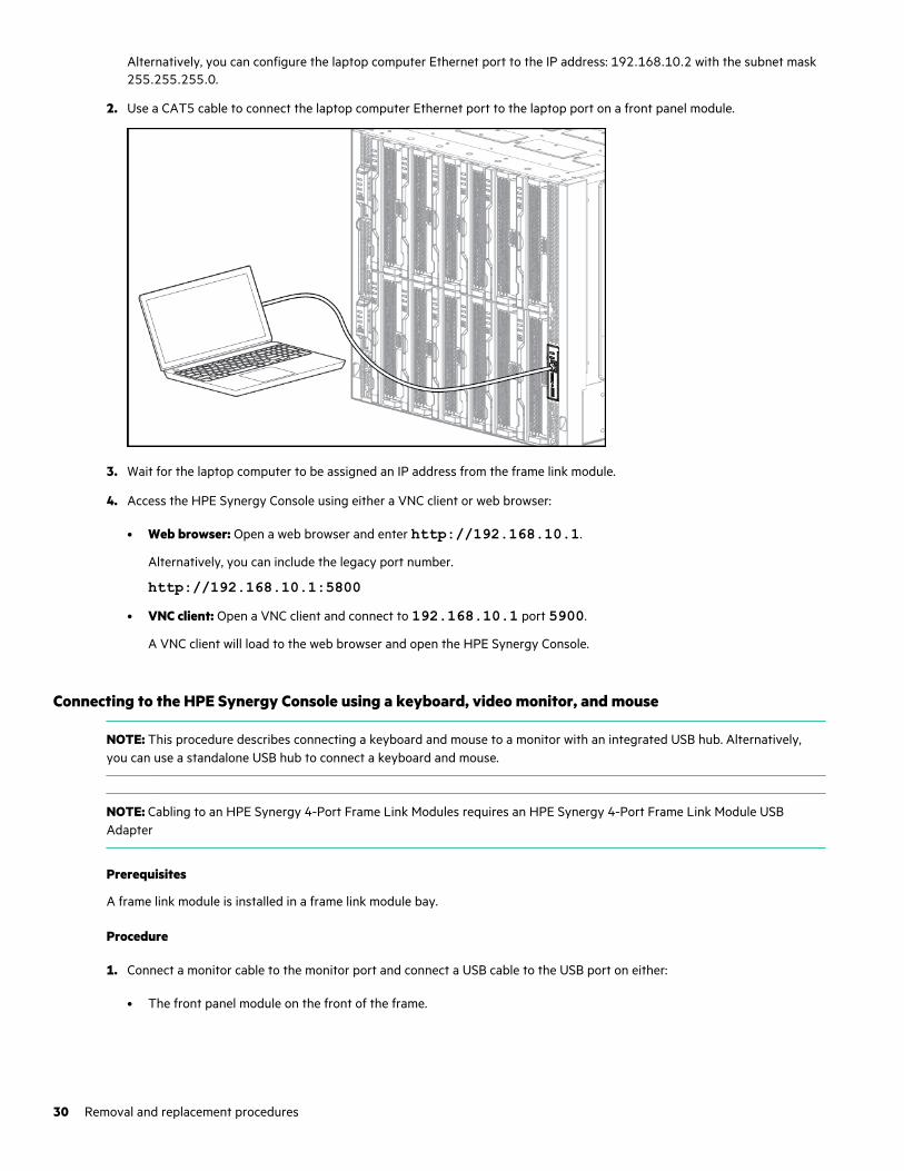
Alternatively, you can configure the laptop computer Ethernet port to the IP address: 192.168.10.2 with the subnet mask255.255.255.0.
2. Use a CAT5 cable to connect the laptop computer Ethernet port to the laptop port on a front panel module.
3. Wait for the laptop computer to be assigned an IP address from the frame link module.
4. Access the HPE Synergy Console using either a VNC client or web browser:
• Web browser: Open a web browser and enter http://192.168.10.1.
Alternatively, you can include the legacy port number.
http://192.168.10.1:5800• VNC client: Open a VNC client and connect to 192.168.10.1 port 5900.
A VNC client will load to the web browser and open the HPE Synergy Console.
Connecting to the HPE Synergy Console using a keyboard, video monitor, and mouse
NOTE: This procedure describes connecting a keyboard and mouse to a monitor with an integrated USB hub. Alternatively,you can use a standalone USB hub to connect a keyboard and mouse.
NOTE: Cabling to an HPE Synergy 4-Port Frame Link Modules requires an HPE Synergy 4-Port Frame Link Module USBAdapter
Prerequisites
A frame link module is installed in a frame link module bay.
Procedure
1. Connect a monitor cable to the monitor port and connect a USB cable to the USB port on either:
• The front panel module on the front of the frame.
30 Removal and replacement procedures
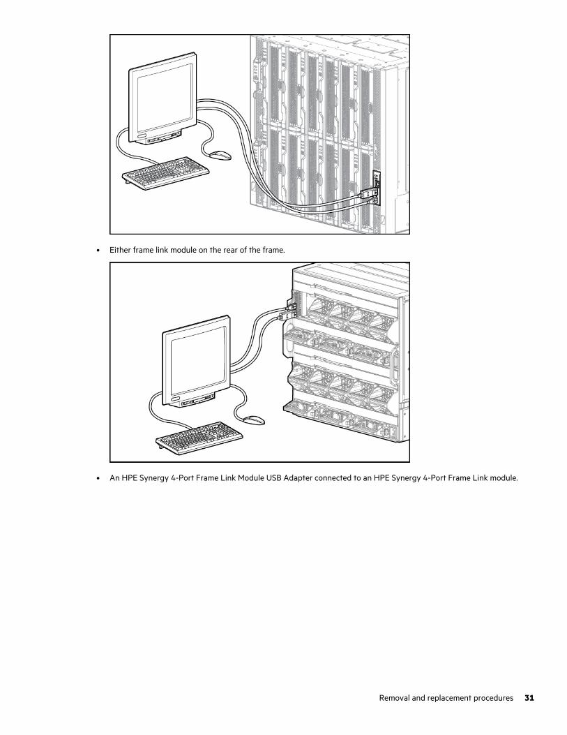
• Either frame link module on the rear of the frame.
• An HPE Synergy 4-Port Frame Link Module USB Adapter connected to an HPE Synergy 4-Port Frame Link module.
Removal and replacement procedures 31
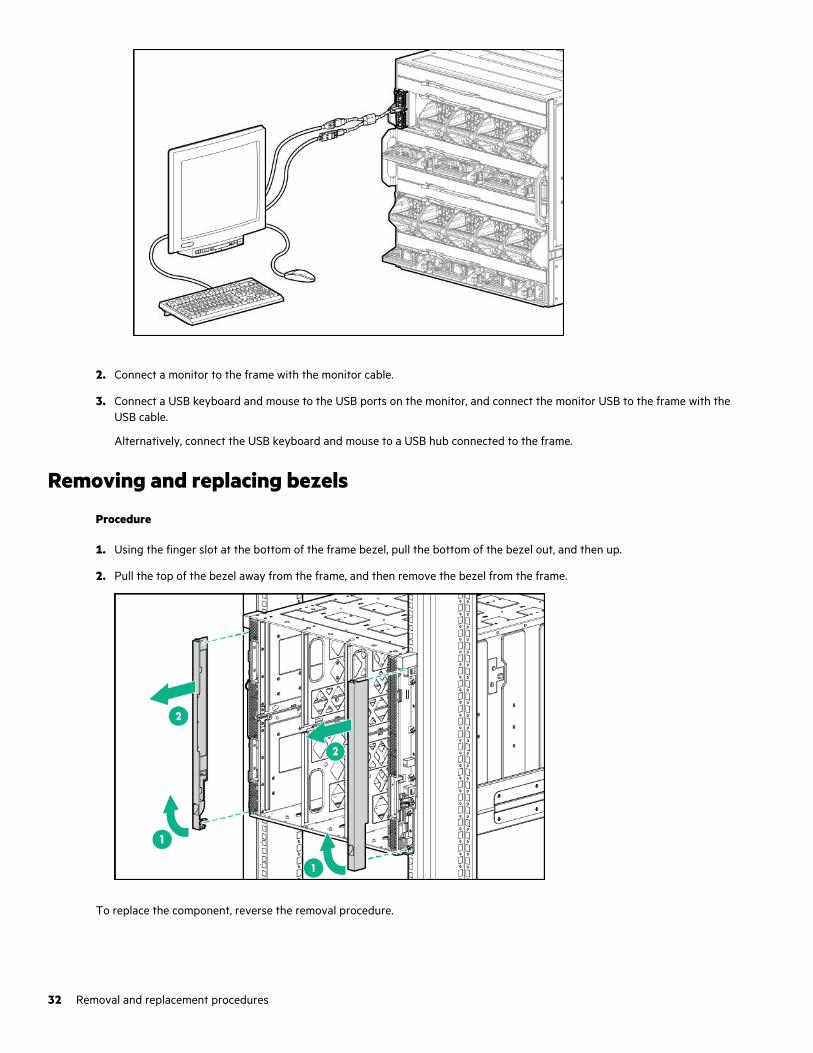
2. Connect a monitor to the frame with the monitor cable.
3. Connect a USB keyboard and mouse to the USB ports on the monitor, and connect the monitor USB to the frame with theUSB cable.
Alternatively, connect the USB keyboard and mouse to a USB hub connected to the frame.
Removing and replacing bezels
Procedure
1. Using the finger slot at the bottom of the frame bezel, pull the bottom of the bezel out, and then up.
2. Pull the top of the bezel away from the frame, and then remove the bezel from the frame.
To replace the component, reverse the removal procedure.
32 Removal and replacement procedures
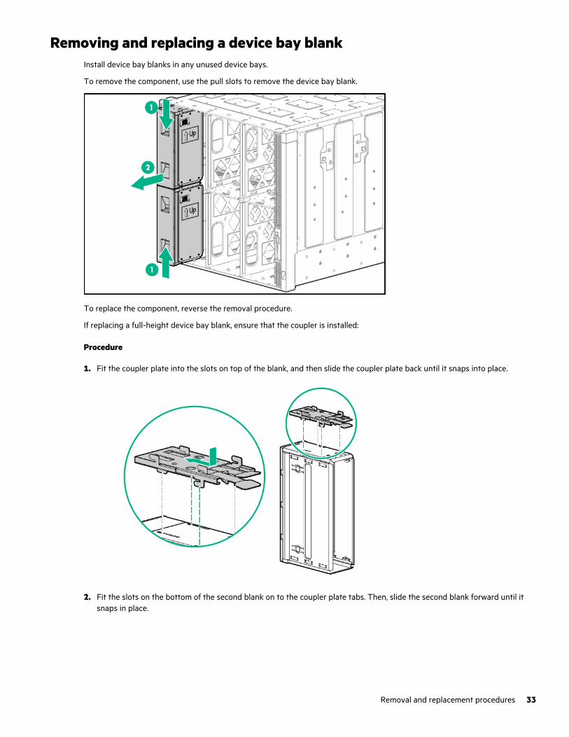
Removing and replacing a device bay blankInstall device bay blanks in any unused device bays.
To remove the component, use the pull slots to remove the device bay blank.
To replace the component, reverse the removal procedure.
If replacing a full-height device bay blank, ensure that the coupler is installed:
Procedure
1. Fit the coupler plate into the slots on top of the blank, and then slide the coupler plate back until it snaps into place.
2. Fit the slots on the bottom of the second blank on to the coupler plate tabs. Then, slide the second blank forward until itsnaps in place.
Removal and replacement procedures 33
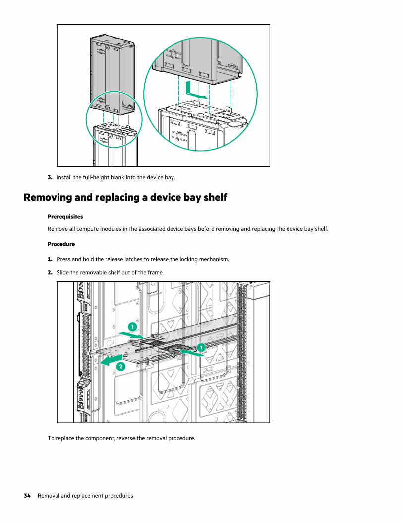
3. Install the full-height blank into the device bay.
Removing and replacing a device bay shelf
Prerequisites
Remove all compute modules in the associated device bays before removing and replacing the device bay shelf.
Procedure
1. Press and hold the release latches to release the locking mechanism.
2. Slide the removable shelf out of the frame.
To replace the component, reverse the removal procedure.
34 Removal and replacement procedures
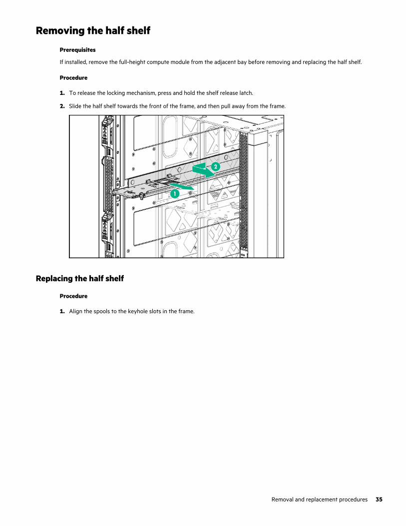
Removing the half shelf
Prerequisites
If installed, remove the full-height compute module from the adjacent bay before removing and replacing the half shelf.
Procedure
1. To release the locking mechanism, press and hold the shelf release latch.
2. Slide the half shelf towards the front of the frame, and then pull away from the frame.
Replacing the half shelf
Procedure
1. Align the spools to the keyhole slots in the frame.
Removal and replacement procedures 35
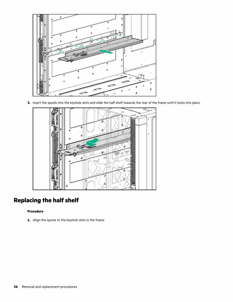
2. Insert the spools into the keyhole slots and slide the half shelf towards the rear of the frame until it locks into place.
Replacing the half shelf
Procedure
1. Align the spools to the keyhole slots in the frame.
36 Removal and replacement procedures
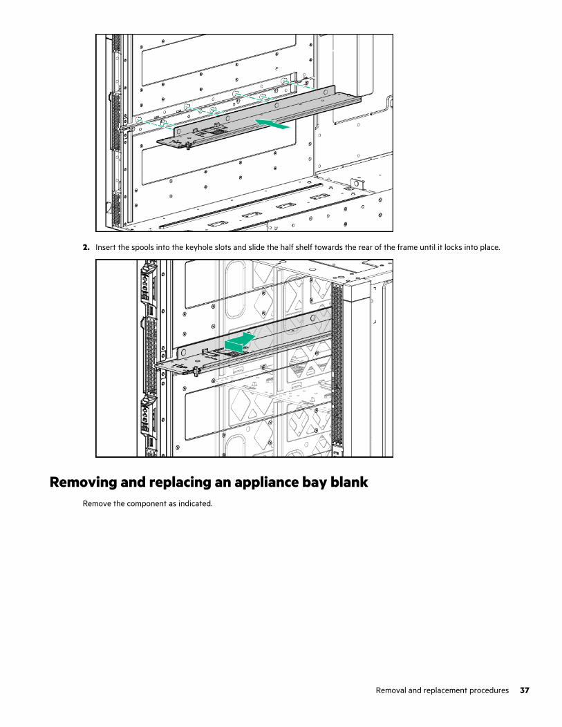
2. Insert the spools into the keyhole slots and slide the half shelf towards the rear of the frame until it locks into place.
Removing and replacing an appliance bay blankRemove the component as indicated.
Removal and replacement procedures 37
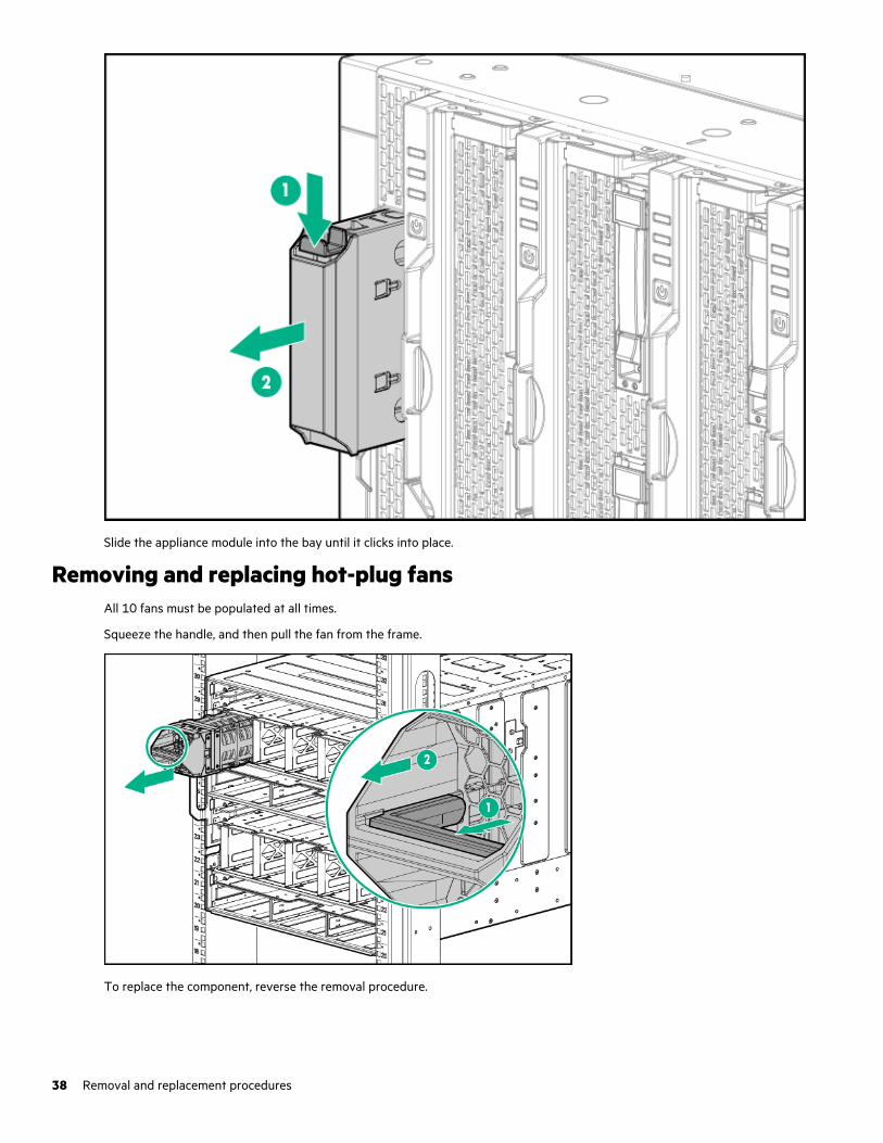
Slide the appliance module into the bay until it clicks into place.
Removing and replacing hot-plug fansAll 10 fans must be populated at all times.
Squeeze the handle, and then pull the fan from the frame.
To replace the component, reverse the removal procedure.
38 Removal and replacement procedures
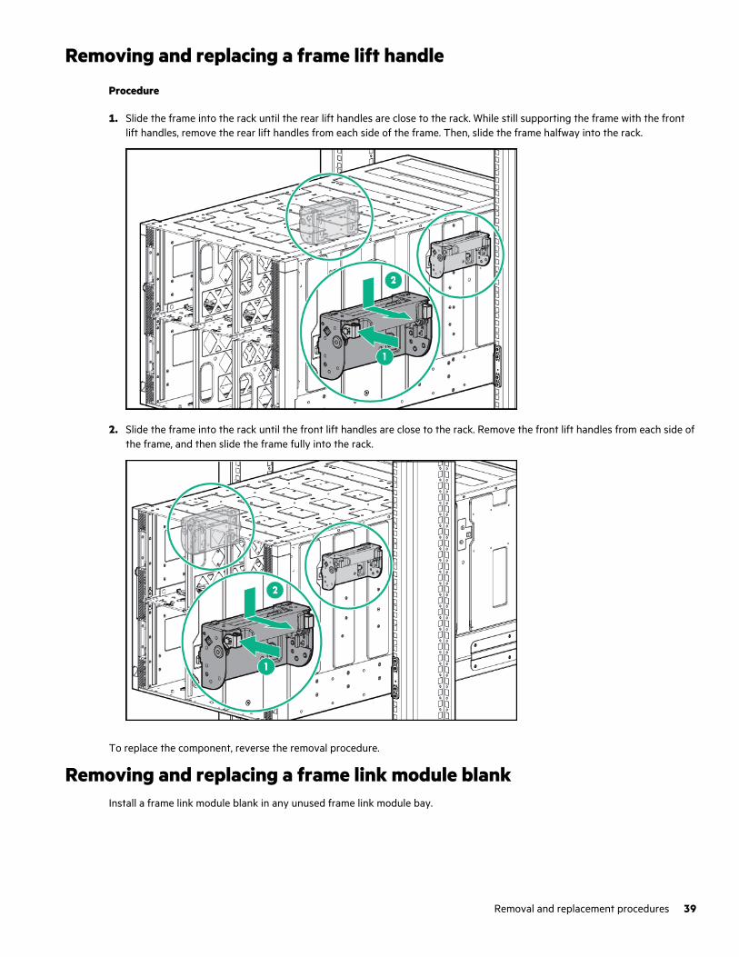
Removing and replacing a frame lift handle
Procedure
1. Slide the frame into the rack until the rear lift handles are close to the rack. While still supporting the frame with the frontlift handles, remove the rear lift handles from each side of the frame. Then, slide the frame halfway into the rack.
2. Slide the frame into the rack until the front lift handles are close to the rack. Remove the front lift handles from each side ofthe frame, and then slide the frame fully into the rack.
To replace the component, reverse the removal procedure.
Removing and replacing a frame link module blankInstall a frame link module blank in any unused frame link module bay.
Removal and replacement procedures 39
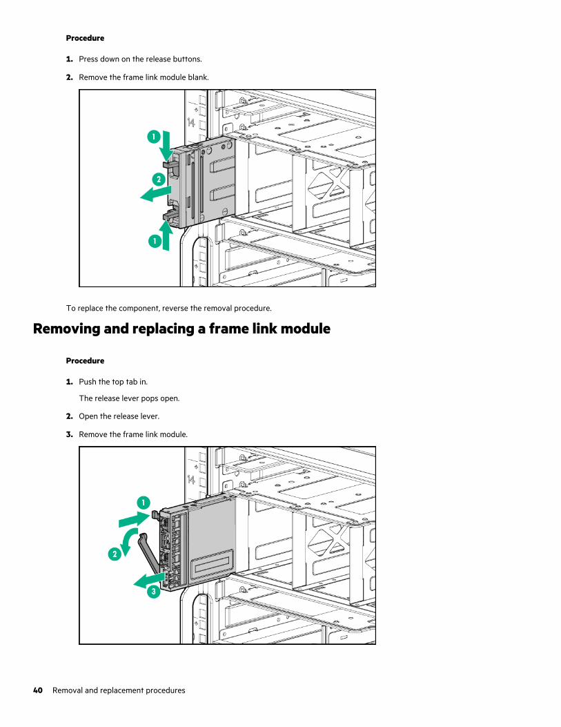
Procedure
1. Press down on the release buttons.
2. Remove the frame link module blank.
To replace the component, reverse the removal procedure.
Removing and replacing a frame link module
Procedure
1. Push the top tab in.
The release lever pops open.
2. Open the release lever.
3. Remove the frame link module.
40 Removal and replacement procedures
To replace the component, reverse the removal procedure.
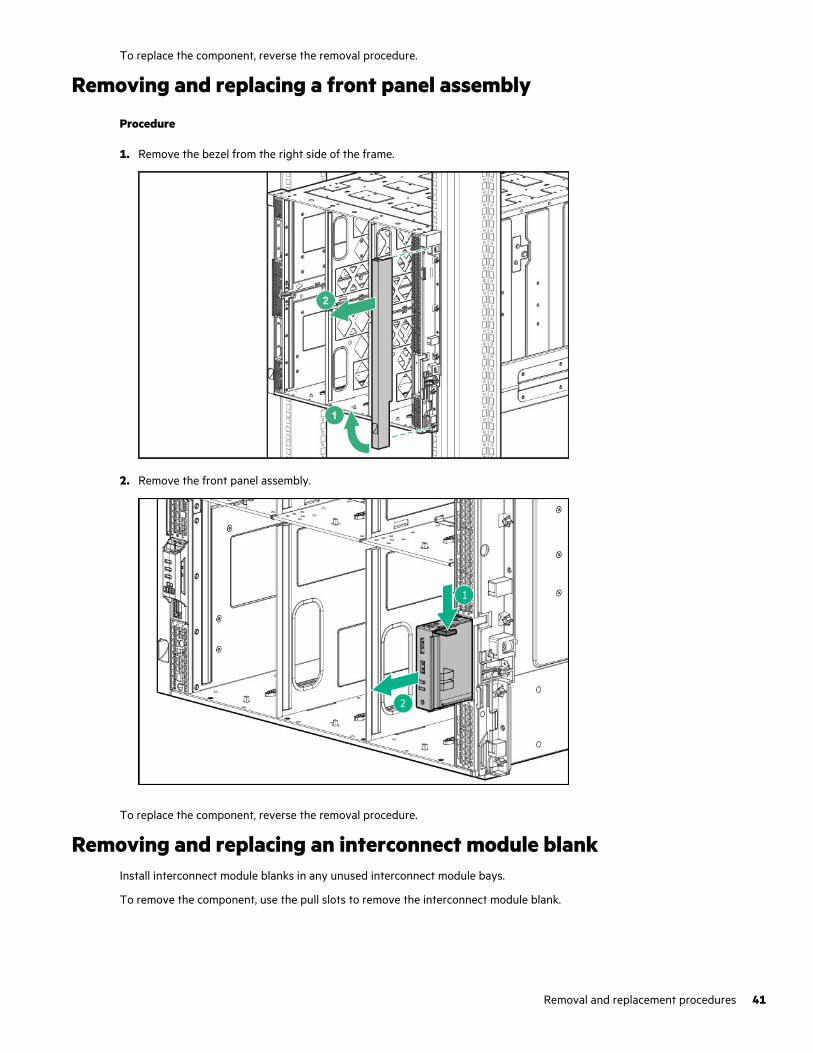
Removing and replacing a front panel assembly
Procedure
1. Remove the bezel from the right side of the frame.
2. Remove the front panel assembly.
To replace the component, reverse the removal procedure.
Removing and replacing an interconnect module blankInstall interconnect module blanks in any unused interconnect module bays.
To remove the component, use the pull slots to remove the interconnect module blank.
Removal and replacement procedures 41
To replace the component, reverse the removal procedure.
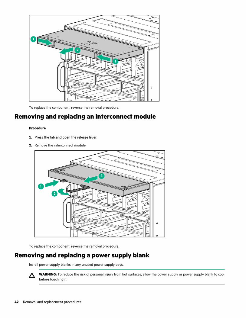
Removing and replacing an interconnect module
Procedure
1. Press the tab and open the release lever.
2. Remove the interconnect module.
To replace the component, reverse the removal procedure.
Removing and replacing a power supply blankInstall power supply blanks in any unused power supply bays.
WARNING: To reduce the risk of personal injury from hot surfaces, allow the power supply or power supply blank to coolbefore touching it.
42 Removal and replacement procedures
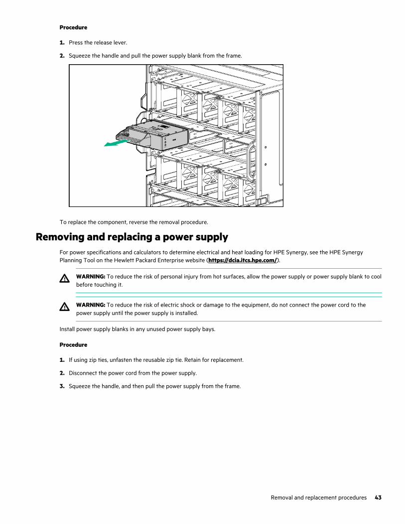
Procedure
1. Press the release lever.
2. Squeeze the handle and pull the power supply blank from the frame.
To replace the component, reverse the removal procedure.
Removing and replacing a power supplyFor power specifications and calculators to determine electrical and heat loading for HPE Synergy, see the HPE SynergyPlanning Tool on the Hewlett Packard Enterprise website (https://dcia.itcs.hpe.com/).
WARNING: To reduce the risk of personal injury from hot surfaces, allow the power supply or power supply blank to coolbefore touching it.
WARNING: To reduce the risk of electric shock or damage to the equipment, do not connect the power cord to thepower supply until the power supply is installed.
Install power supply blanks in any unused power supply bays.
Procedure
1. If using zip ties, unfasten the reusable zip tie. Retain for replacement.
2. Disconnect the power cord from the power supply.
3. Squeeze the handle, and then pull the power supply from the frame.
Removal and replacement procedures 43
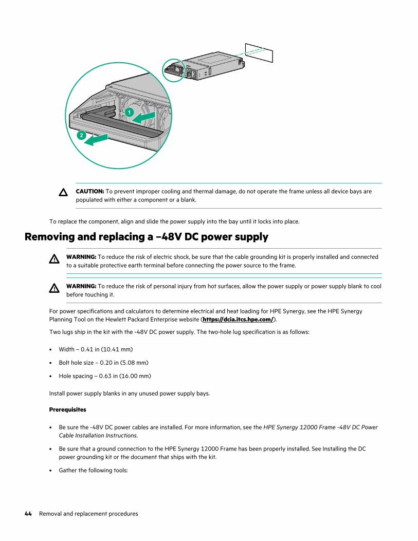
CAUTION: To prevent improper cooling and thermal damage, do not operate the frame unless all device bays arepopulated with either a component or a blank.
To replace the component, align and slide the power supply into the bay until it locks into place.
Removing and replacing a –48V DC power supply
WARNING: To reduce the risk of electric shock, be sure that the cable grounding kit is properly installed and connectedto a suitable protective earth terminal before connecting the power source to the frame.
WARNING: To reduce the risk of personal injury from hot surfaces, allow the power supply or power supply blank to coolbefore touching it.
For power specifications and calculators to determine electrical and heat loading for HPE Synergy, see the HPE SynergyPlanning Tool on the Hewlett Packard Enterprise website (https://dcia.itcs.hpe.com/).
Two lugs ship in the kit with the -48V DC power supply. The two-hole lug specification is as follows:
• Width – 0.41 in (10.41 mm)
• Bolt hole size – 0.20 in (5.08 mm)
• Hole spacing – 0.63 in (16.00 mm)
Install power supply blanks in any unused power supply bays.
Prerequisites
• Be sure the -48V DC power cables are installed. For more information, see the HPE Synergy 12000 Frame -48V DC PowerCable Installation Instructions.
• Be sure that a ground connection to the HPE Synergy 12000 Frame has been properly installed. See Installing the DCpower grounding kit or the document that ships with the kit.
• Gather the following tools:
44 Removal and replacement procedures
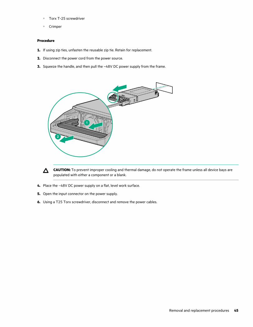
◦ Torx T-25 screwdriver
◦ Crimper
Procedure
1. If using zip ties, unfasten the reusable zip tie. Retain for replacement.
2. Disconnect the power cord from the power source.
3. Squeeze the handle, and then pull the –48V DC power supply from the frame.
CAUTION: To prevent improper cooling and thermal damage, do not operate the frame unless all device bays arepopulated with either a component or a blank.
4. Place the –48V DC power supply on a flat, level work surface.
5. Open the input connector on the power supply.
6. Using a T25 Torx screwdriver, disconnect and remove the power cables.
Removal and replacement procedures 45
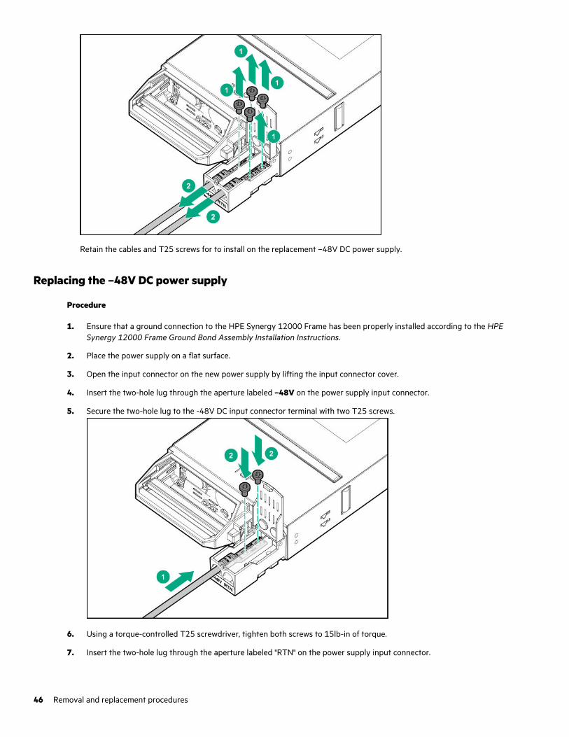
Retain the cables and T25 screws for to install on the replacement –48V DC power supply.
Replacing the –48V DC power supply
Procedure
1. Ensure that a ground connection to the HPE Synergy 12000 Frame has been properly installed according to the HPESynergy 12000 Frame Ground Bond Assembly Installation Instructions.
2. Place the power supply on a flat surface.
3. Open the input connector on the new power supply by lifting the input connector cover.
4. Insert the two-hole lug through the aperture labeled –48V on the power supply input connector.
5. Secure the two-hole lug to the -48V DC input connector terminal with two T25 screws.
6. Using a torque-controlled T25 screwdriver, tighten both screws to 15lb-in of torque.
7. Insert the two-hole lug through the aperture labeled "RTN" on the power supply input connector.
46 Removal and replacement procedures
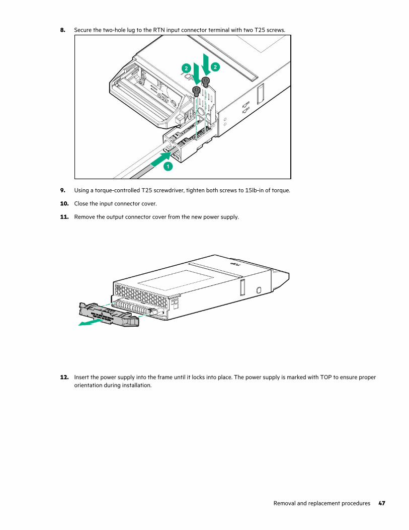
8. Secure the two-hole lug to the RTN input connector terminal with two T25 screws.
9. Using a torque-controlled T25 screwdriver, tighten both screws to 15lb-in of torque.
10. Close the input connector cover.
11. Remove the output connector cover from the new power supply.
12. Insert the power supply into the frame until it locks into place. The power supply is marked with TOP to ensure properorientation during installation.
Removal and replacement procedures 47
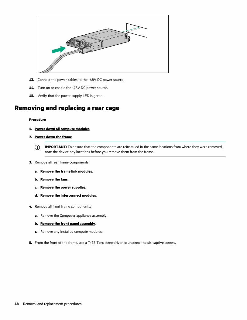
13. Connect the power cables to the -48V DC power source.
14. Turn on or enable the -48V DC power source.
15. Verify that the power supply LED is green.
Removing and replacing a rear cage
Procedure
1. Power down all compute modules.
2. Power down the frame.
IMPORTANT: To ensure that the components are reinstalled in the same locations from where they were removed,note the device bay locations before you remove them from the frame.
3. Remove all rear frame components:
a. Remove the frame link modules.
b. Remove the fans.
c. Remove the power supplies.
d. Remove the interconnect modules.
4. Remove all front frame components:
a. Remove the Composer appliance assembly.
b. Remove the front panel assembly.
c. Remove any installed compute modules.
5. From the front of the frame, use a T-25 Torx screwdriver to unscrew the six captive screws.
48 Removal and replacement procedures
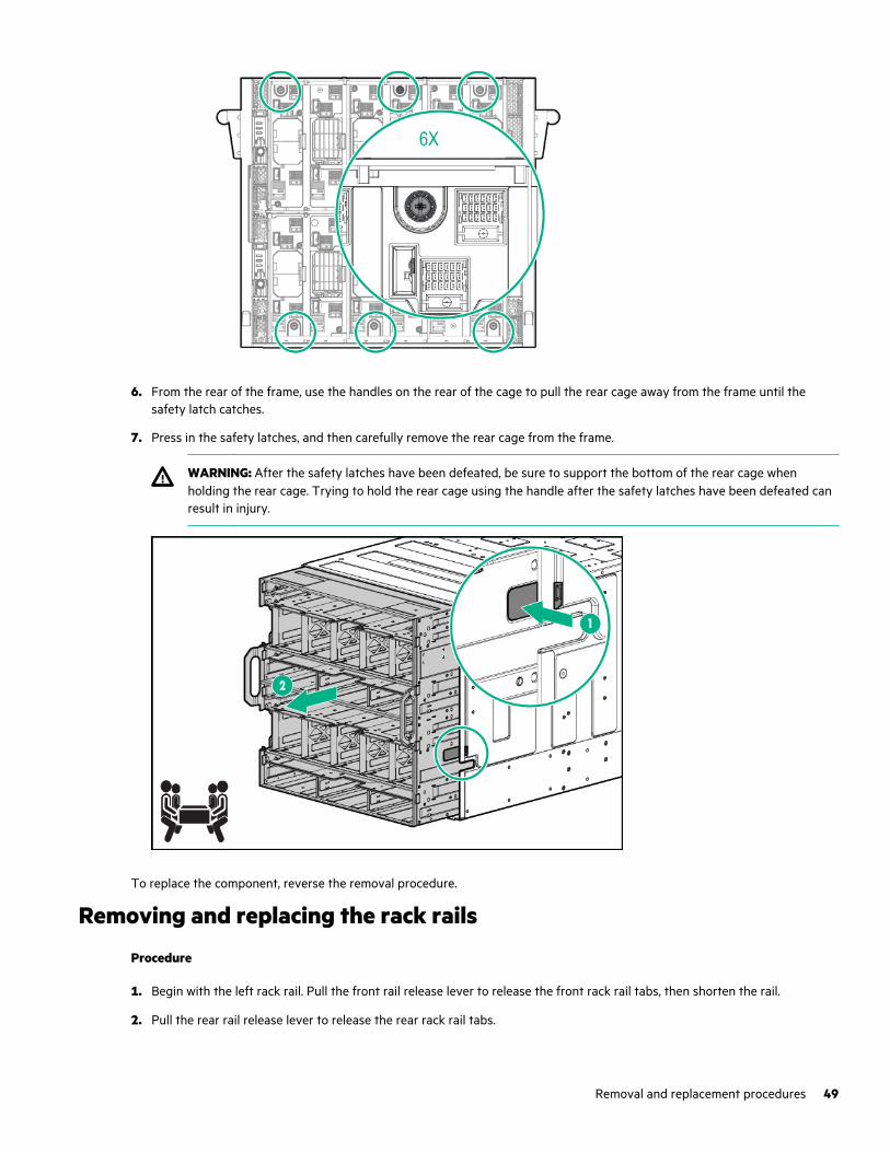
6. From the rear of the frame, use the handles on the rear of the cage to pull the rear cage away from the frame until thesafety latch catches.
7. Press in the safety latches, and then carefully remove the rear cage from the frame.
WARNING: After the safety latches have been defeated, be sure to support the bottom of the rear cage whenholding the rear cage. Trying to hold the rear cage using the handle after the safety latches have been defeated canresult in injury.
To replace the component, reverse the removal procedure.
Removing and replacing the rack rails
Procedure
1. Begin with the left rack rail. Pull the front rail release lever to release the front rack rail tabs, then shorten the rail.
2. Pull the rear rail release lever to release the rear rack rail tabs.
Removal and replacement procedures 49
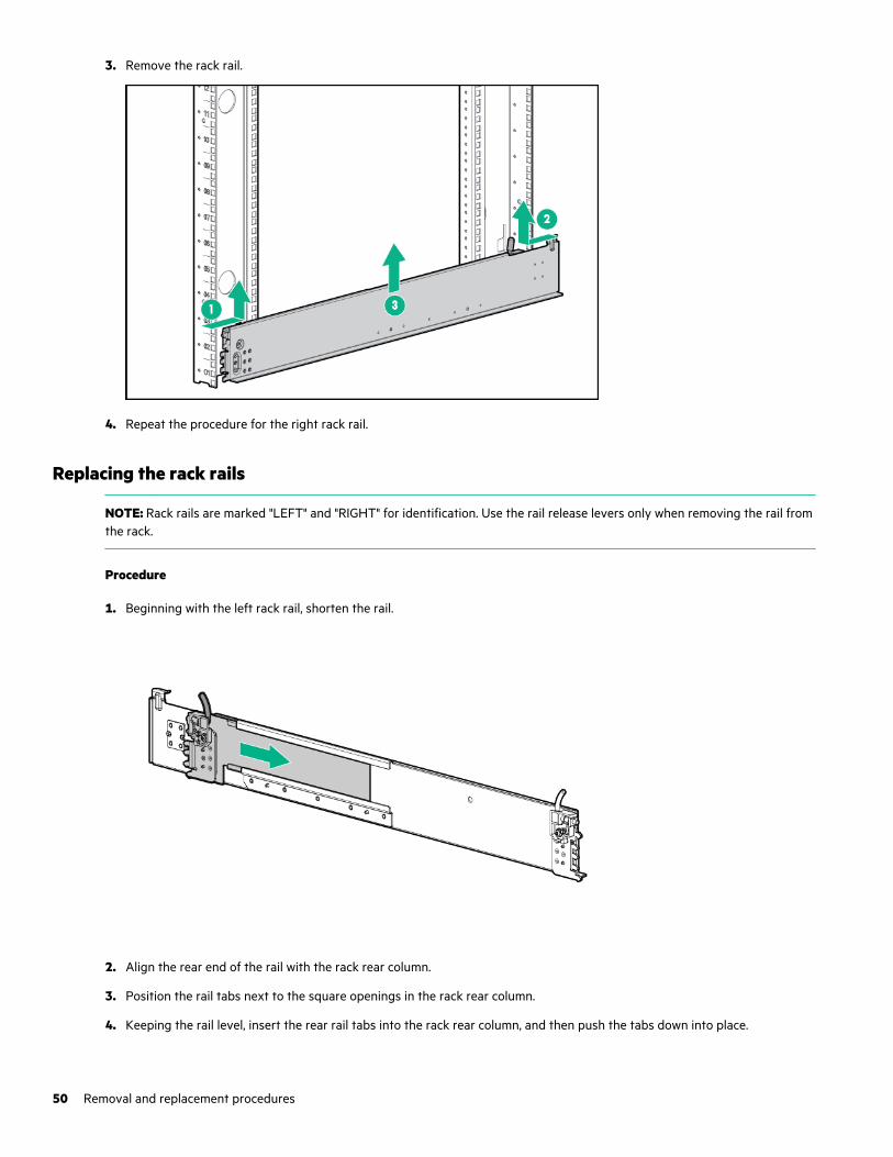
3. Remove the rack rail.
4. Repeat the procedure for the right rack rail.
Replacing the rack rails
NOTE: Rack rails are marked "LEFT" and "RIGHT" for identification. Use the rail release levers only when removing the rail fromthe rack.
Procedure
1. Beginning with the left rack rail, shorten the rail.
2. Align the rear end of the rail with the rack rear column.
3. Position the rail tabs next to the square openings in the rack rear column.
4. Keeping the rail level, insert the rear rail tabs into the rack rear column, and then push the tabs down into place.
50 Removal and replacement procedures
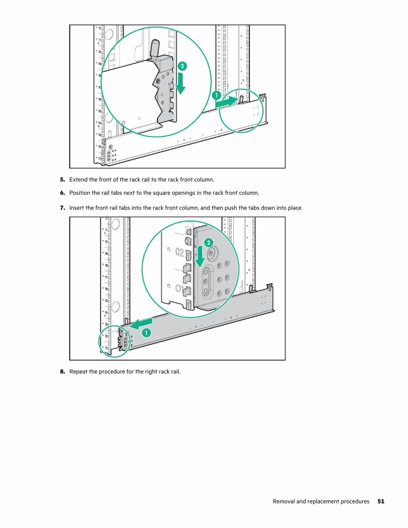
5. Extend the front of the rack rail to the rack front column.
6. Position the rail tabs next to the square openings in the rack front column.
7. Insert the front rail tabs into the rack front column, and then push the tabs down into place.
8. Repeat the procedure for the right rack rail.
Removal and replacement procedures 51
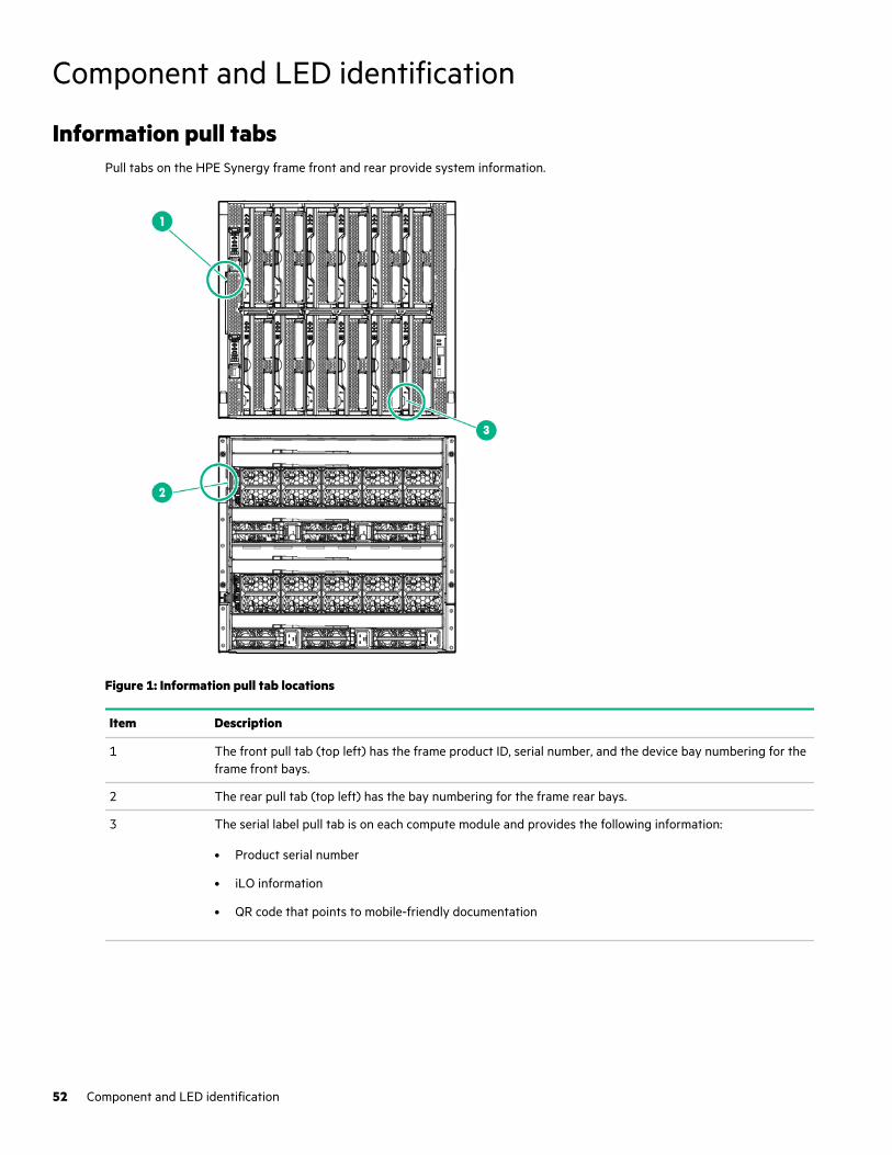
Component and LED identification
Information pull tabsPull tabs on the HPE Synergy frame front and rear provide system information.
Figure 1: Information pull tab locations
Item Description
1 The front pull tab (top left) has the frame product ID, serial number, and the device bay numbering for theframe front bays.
2 The rear pull tab (top left) has the bay numbering for the frame rear bays.
3 The serial label pull tab is on each compute module and provides the following information:
• Product serial number
• iLO information
• QR code that points to mobile-friendly documentation
52 Component and LED identification
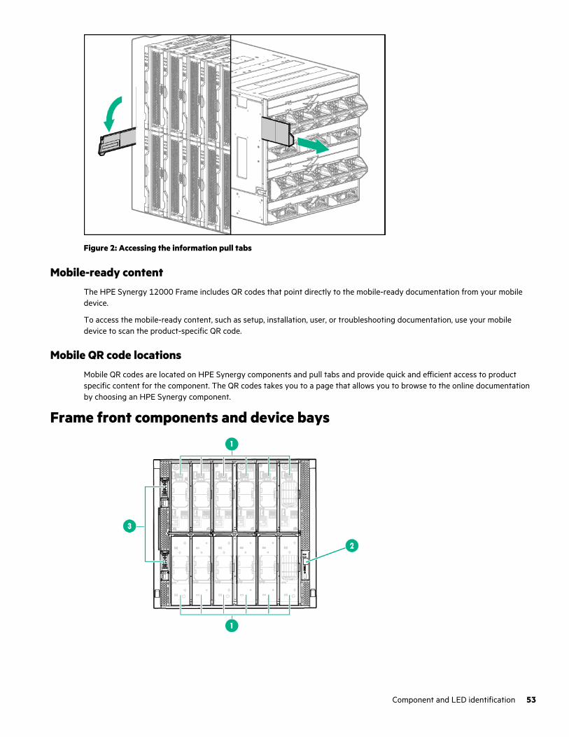
Figure 2: Accessing the information pull tabs
Mobile-ready contentThe HPE Synergy 12000 Frame includes QR codes that point directly to the mobile-ready documentation from your mobiledevice.
To access the mobile-ready content, such as setup, installation, user, or troubleshooting documentation, use your mobiledevice to scan the product-specific QR code.
Mobile QR code locationsMobile QR codes are located on HPE Synergy components and pull tabs and provide quick and efficient access to productspecific content for the component. The QR codes takes you to a page that allows you to browse to the online documentationby choosing an HPE Synergy component.
Frame front components and device bays
Component and LED identification 53
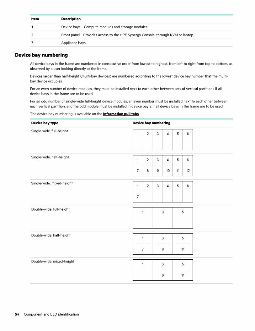
Item Description
1 Device bays—Compute modules and storage modules.
2 Front panel—Provides access to the HPE Synergy Console, through KVM or laptop.
3 Appliance bays.
Device bay numberingAll device bays in the frame are numbered in consecutive order from lowest to highest, from left to right from top to bottom, asobserved by a user looking directly at the frame.
Devices larger than half-height (multi-bay devices) are numbered according to the lowest device bay number that the multi-bay device occupies.
For an even number of device modules, they must be installed next to each other between sets of vertical partitions if alldevice bays in the frame are to be used.
For an odd number of single-wide full-height device modules, an even number must be installed next to each other betweeneach vertical partition, and the odd module must be installed in device bay 2 if all device bays in the frame are to be used.
The device bay numbering is available on the Information pull tabs.
Device bay type Device bay numbering
Single-wide, full-height
Single-wide, half-height
Single-wide, mixed-height
Double-wide, full-height
Double-wide, half-height
Double-wide, mixed-height
54 Component and LED identification
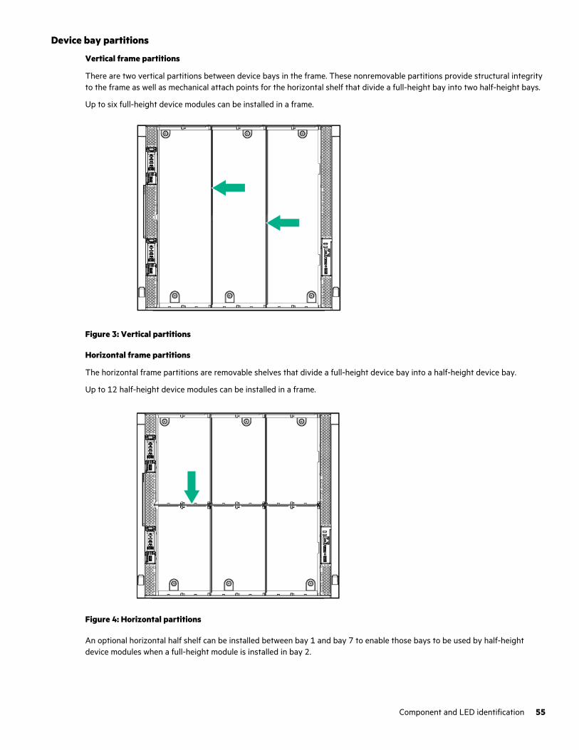
Device bay partitions
Vertical frame partitions
There are two vertical partitions between device bays in the frame. These nonremovable partitions provide structural integrityto the frame as well as mechanical attach points for the horizontal shelf that divide a full-height bay into two half-height bays.
Up to six full-height device modules can be installed in a frame.
Figure 3: Vertical partitions
Horizontal frame partitions
The horizontal frame partitions are removable shelves that divide a full-height device bay into a half-height device bay.
Up to 12 half-height device modules can be installed in a frame.
Figure 4: Horizontal partitions
An optional horizontal half shelf can be installed between bay 1 and bay 7 to enable those bays to be used by half-heightdevice modules when a full-height module is installed in bay 2.
Component and LED identification 55
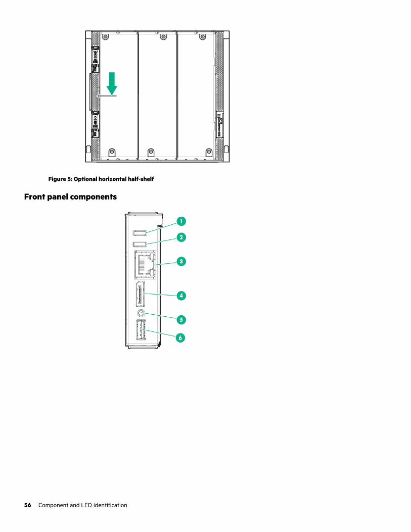
Figure 5: Optional horizontal half-shelf
Front panel components
56 Component and LED identification
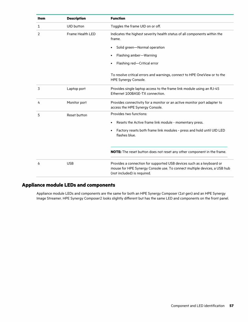
Item Description Function
1 UID button Toggles the frame UID on or off.
2 Frame Health LED Indicates the highest severity health status of all components within theframe.
• Solid green—Normal operation
• Flashing amber—Warning
• Flashing red—Critical error
To resolve critical errors and warnings, connect to HPE OneView or to theHPE Synergy Console.
3 Laptop port Provides single laptop access to the frame link module using an RJ-45Ethernet 100BASE-TX connection.
4 Monitor port Provides connectivity for a monitor or an active monitor port adapter toaccess the HPE Synergy Console.
5 Reset button Provides two functions:
• Resets the Active frame link module - momentary press.
• Factory resets both frame link modules - press and hold until UID LEDflashes blue.
NOTE: The reset button does not reset any other component in the frame.
6 USB Provides a connection for supported USB devices such as a keyboard ormouse for HPE Synergy Console use. To connect multiple devices, a USB hub(not included) is required.
Appliance module LEDs and componentsAppliance module LEDs and components are the same for both an HPE Synergy Composer (1st gen) and an HPE SynergyImage Streamer. HPE Synergy Composer2 looks slightly different but has the same LED and components on the front panel.
Component and LED identification 57
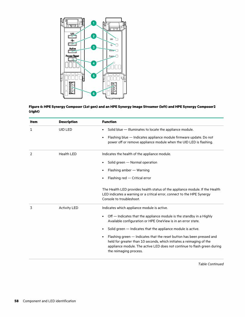
Figure 6: HPE Synergy Composer (1st gen) and an HPE Synergy Image Streamer (left) and HPE Synergy Composer2(right)
Item Description Function
1 UID LED • Solid blue — Illuminates to locate the appliance module.
• Flashing blue — Indicates appliance module firmware update. Do notpower off or remove appliance module when the UID LED is flashing.
2 Health LED Indicates the health of the appliance module.
• Solid green — Normal operation
• Flashing amber — Warning
• Flashing red — Critical error
The Health LED provides health status of the appliance module. If the HealthLED indicates a warning or a critical error, connect to the HPE SynergyConsole to troubleshoot.
3 Activity LED Indicates which appliance module is active.
• Off — Indicates that the appliance module is the standby in a HighlyAvailable configuration or HPE OneView is in an error state.
• Solid green — Indicates that the appliance module is active.
• Flashing green — Indicates that the reset button has been pressed andheld for greater than 10 seconds, which initiates a reimaging of theappliance module. The active LED does not continue to flash green duringthe reimaging process.
Table Continued
58 Component and LED identification
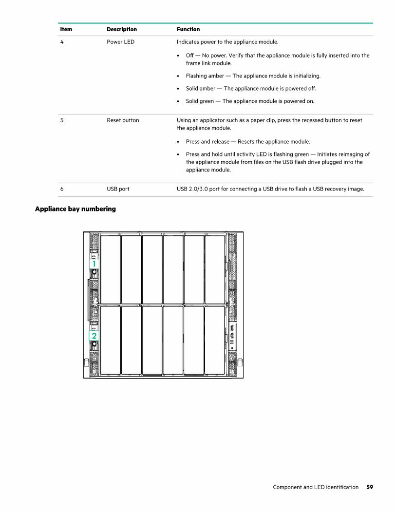
Item Description Function
4 Power LED Indicates power to the appliance module.
• Off — No power. Verify that the appliance module is fully inserted into theframe link module.
• Flashing amber — The appliance module is initializing.
• Solid amber — The appliance module is powered off.
• Solid green — The appliance module is powered on.
5 Reset button Using an applicator such as a paper clip, press the recessed button to resetthe appliance module.
• Press and release — Resets the appliance module.
• Press and hold until activity LED is flashing green — Initiates reimaging ofthe appliance module from files on the USB flash drive plugged into theappliance module.
6 USB port USB 2.0/3.0 port for connecting a USB drive to flash a USB recovery image.
Appliance bay numbering
Component and LED identification 59
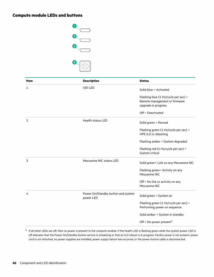
Compute module LEDs and buttons
Item Description Status
1 UID LEDSolid blue = Activated
Flashing blue (1 Hz/cycle per sec) =Remote management or firmwareupgrade in progress
Off = Deactivated
2 Health status LEDSolid green = Normal
Flashing green (1 Hz/cycle per sec) =HPE iLO is rebooting
Flashing amber = System degraded
Flashing red (1 Hz/cycle per sec) =System critical
3 Mezzanine NIC status LEDSolid green= Link on any Mezzanine NIC
Flashing green= Activity on anyMezzanine NIC
Off = No link or activity on anyMezzanine NIC
4 Power On/Standby button and systempower LED
Solid green = System on
Flashing green (1 Hz/cycle per sec) =Performing power on sequence
Solid amber = System in standby
Off = No power present1
1 If all other LEDs are off, then no power is present to the compute module. If the health LED is flashing green while the system power LED isoff indicates that the Power On/Standby button service is initializing or that an iLO reboot is in progress. Facility power is not present, powercord is not attached, no power supplies are installed, power supply failure has occurred, or the power button cable is disconnected.
60 Component and LED identification
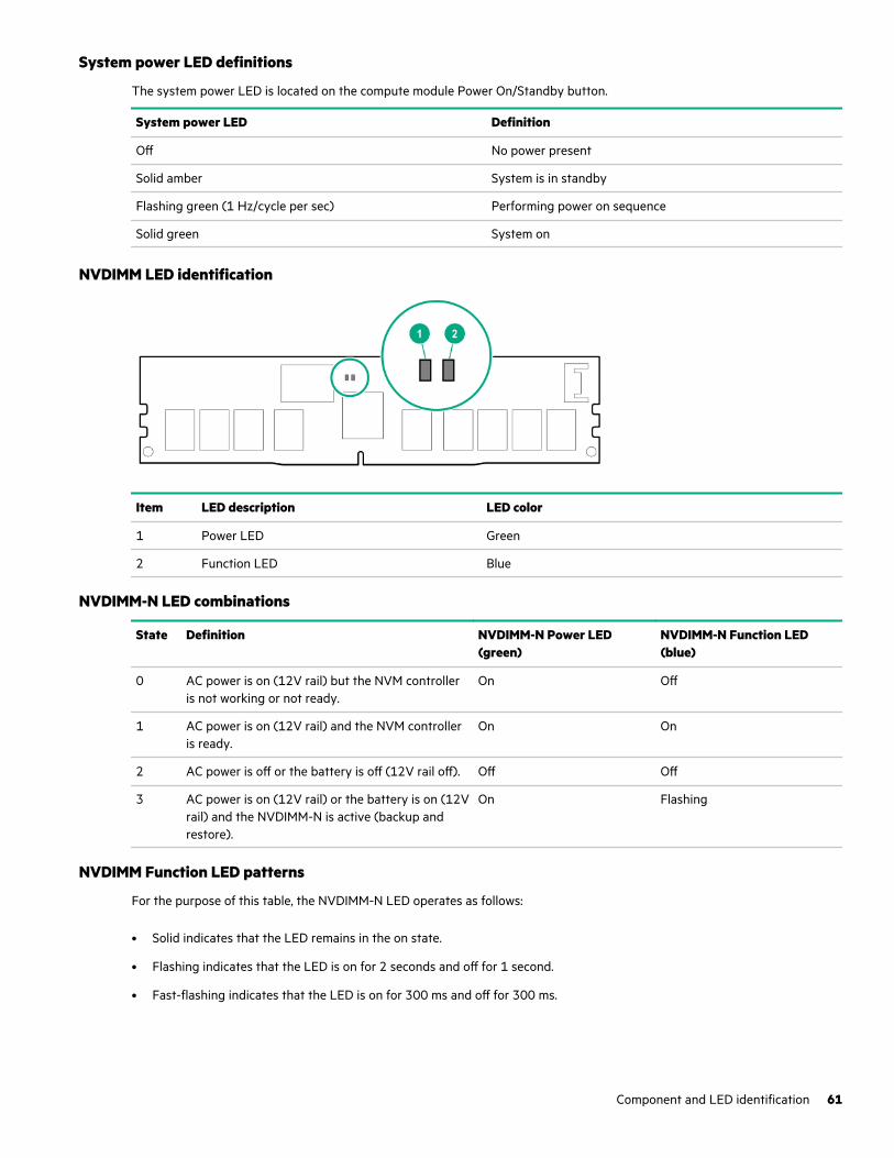
System power LED definitions
The system power LED is located on the compute module Power On/Standby button.
System power LED Definition
Off No power present
Solid amber System is in standby
Flashing green (1 Hz/cycle per sec) Performing power on sequence
Solid green System on
NVDIMM LED identification
Item LED description LED color
1 Power LED Green
2 Function LED Blue
NVDIMM-N LED combinations
State Definition NVDIMM-N Power LED(green)
NVDIMM-N Function LED(blue)
0 AC power is on (12V rail) but the NVM controlleris not working or not ready.
On Off
1 AC power is on (12V rail) and the NVM controlleris ready.
On On
2 AC power is off or the battery is off (12V rail off). Off Off
3 AC power is on (12V rail) or the battery is on (12Vrail) and the NVDIMM-N is active (backup andrestore).
On Flashing
NVDIMM Function LED patterns
For the purpose of this table, the NVDIMM-N LED operates as follows:
• Solid indicates that the LED remains in the on state.
• Flashing indicates that the LED is on for 2 seconds and off for 1 second.
• Fast-flashing indicates that the LED is on for 300 ms and off for 300 ms.
Component and LED identification 61
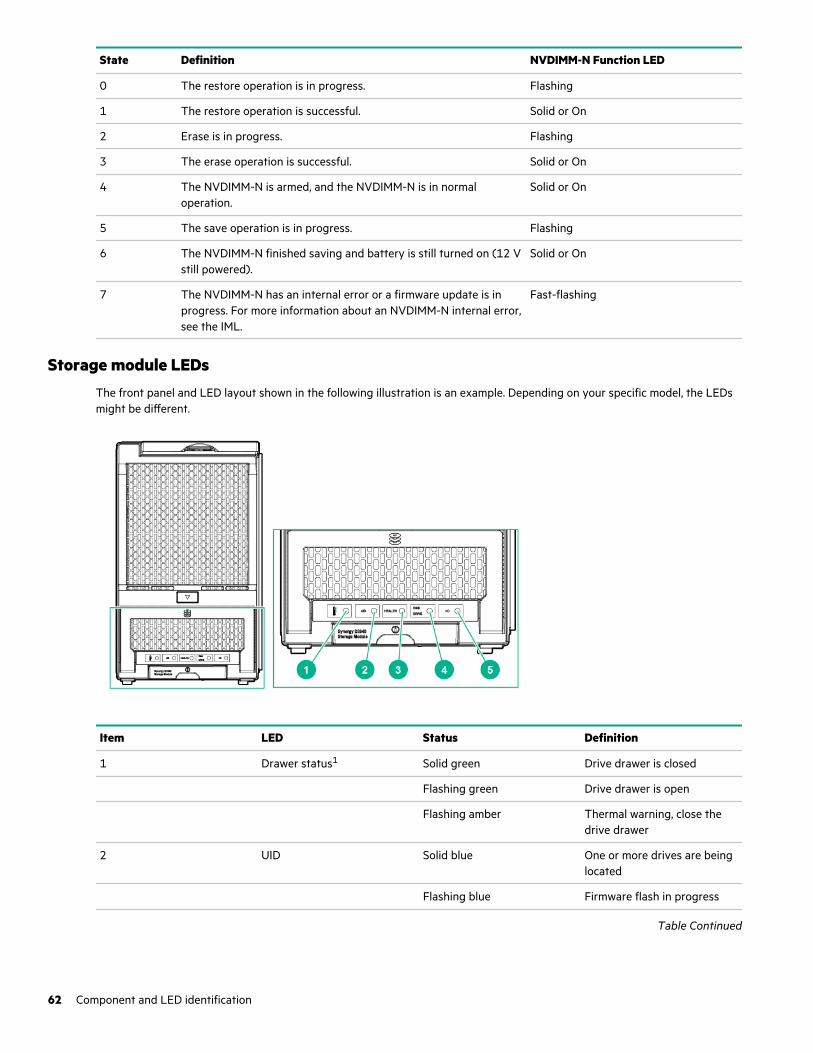
State Definition NVDIMM-N Function LED
0 The restore operation is in progress. Flashing
1 The restore operation is successful. Solid or On
2 Erase is in progress. Flashing
3 The erase operation is successful. Solid or On
4 The NVDIMM-N is armed, and the NVDIMM-N is in normaloperation.
Solid or On
5 The save operation is in progress. Flashing
6 The NVDIMM-N finished saving and battery is still turned on (12 Vstill powered).
Solid or On
7 The NVDIMM-N has an internal error or a firmware update is inprogress. For more information about an NVDIMM-N internal error,see the IML.
Fast-flashing
Storage module LEDsThe front panel and LED layout shown in the following illustration is an example. Depending on your specific model, the LEDsmight be different.
Item LED Status Definition
1 Drawer status1 Solid green Drive drawer is closed
Flashing green Drive drawer is open
Flashing amber Thermal warning, close thedrive drawer
2 UID Solid blue One or more drives are beinglocated
Flashing blue Firmware flash in progress
Table Continued
62 Component and LED identification
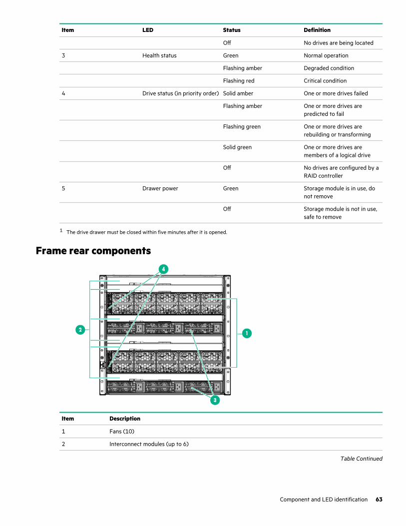
Item LED Status Definition
Off No drives are being located
3 Health status Green Normal operation
Flashing amber Degraded condition
Flashing red Critical condition
4 Drive status (in priority order) Solid amber One or more drives failed
Flashing amber One or more drives arepredicted to fail
Flashing green One or more drives arerebuilding or transforming
Solid green One or more drives aremembers of a logical drive
Off No drives are configured by aRAID controller
5 Drawer power Green Storage module is in use, donot remove
Off Storage module is not in use,safe to remove
1 The drive drawer must be closed within five minutes after it is opened.
Frame rear components
Item Description
1 Fans (10)
2 Interconnect modules (up to 6)
Table Continued
Component and LED identification 63
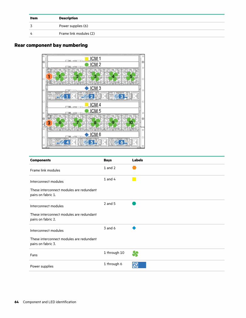
Item Description
3 Power supplies (6)
4 Frame link modules (2)
Rear component bay numbering
Components Bays Labels
Frame link modules1 and 2
Interconnect modules
These interconnect modules are redundantpairs on fabric 1.
1 and 4
Interconnect modules
These interconnect modules are redundantpairs on fabric 2.
2 and 5
Interconnect modules
These interconnect modules are redundantpairs on fabric 3.
3 and 6
Fans1 through 10
Power supplies1 through 6
64 Component and LED identification
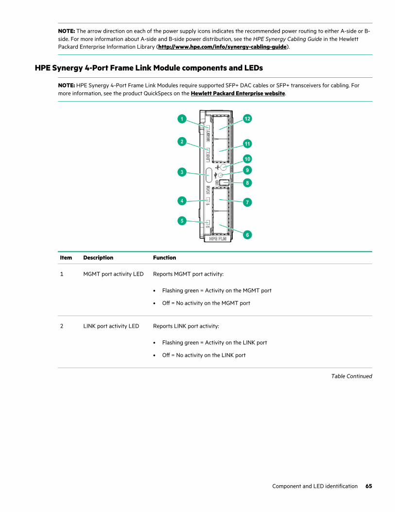
NOTE: The arrow direction on each of the power supply icons indicates the recommended power routing to either A-side or B-side. For more information about A-side and B-side power distribution, see the HPE Synergy Cabling Guide in the HewlettPackard Enterprise Information Library (http://www.hpe.com/info/synergy-cabling-guide).
HPE Synergy 4-Port Frame Link Module components and LEDs
NOTE: HPE Synergy 4-Port Frame Link Modules require supported SFP+ DAC cables or SFP+ transceivers for cabling. Formore information, see the product QuickSpecs on the Hewlett Packard Enterprise website.
Item Description Function
1 MGMT port activity LED Reports MGMT port activity:
• Flashing green = Activity on the MGMT port
• Off = No activity on the MGMT port
2 LINK port activity LED Reports LINK port activity:
• Flashing green = Activity on the LINK port
• Off = No activity on the LINK port
Table Continued
Component and LED identification 65
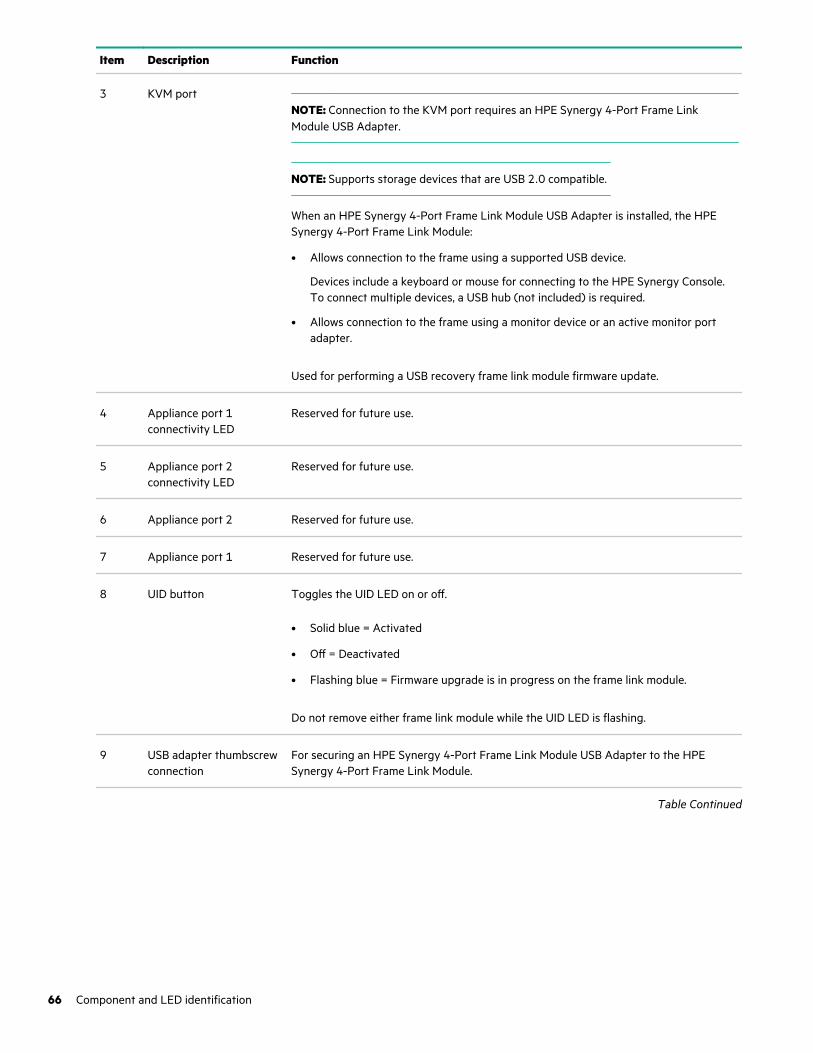
Item Description Function
3 KVM portNOTE: Connection to the KVM port requires an HPE Synergy 4-Port Frame LinkModule USB Adapter.
NOTE: Supports storage devices that are USB 2.0 compatible.
When an HPE Synergy 4-Port Frame Link Module USB Adapter is installed, the HPESynergy 4-Port Frame Link Module:
• Allows connection to the frame using a supported USB device.
Devices include a keyboard or mouse for connecting to the HPE Synergy Console.To connect multiple devices, a USB hub (not included) is required.
• Allows connection to the frame using a monitor device or an active monitor portadapter.
Used for performing a USB recovery frame link module firmware update.
4 Appliance port 1connectivity LED
Reserved for future use.
5 Appliance port 2connectivity LED
Reserved for future use.
6 Appliance port 2 Reserved for future use.
7 Appliance port 1 Reserved for future use.
8 UID button Toggles the UID LED on or off.
• Solid blue = Activated
• Off = Deactivated
• Flashing blue = Firmware upgrade is in progress on the frame link module.
Do not remove either frame link module while the UID LED is flashing.
9 USB adapter thumbscrewconnection
For securing an HPE Synergy 4-Port Frame Link Module USB Adapter to the HPESynergy 4-Port Frame Link Module.
Table Continued
66 Component and LED identification
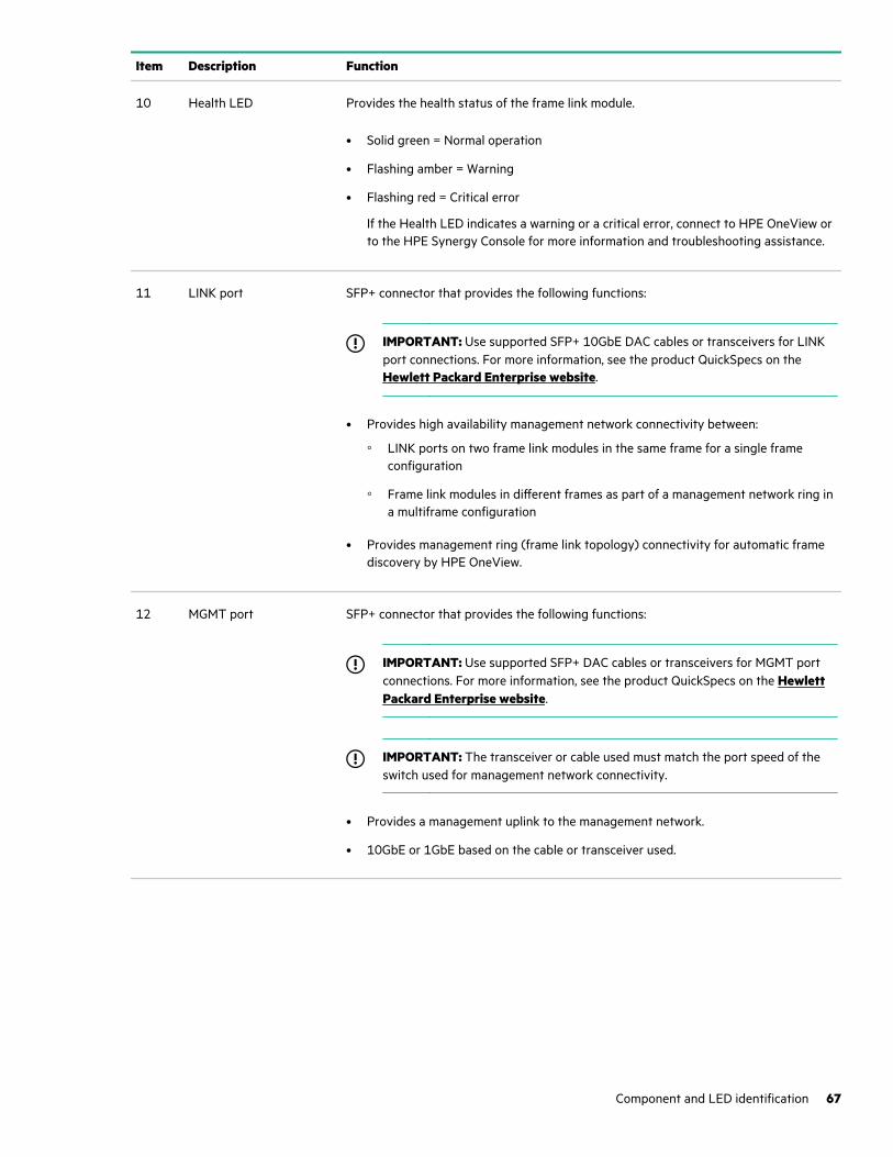
Item Description Function
10 Health LED Provides the health status of the frame link module.
• Solid green = Normal operation
• Flashing amber = Warning
• Flashing red = Critical error
If the Health LED indicates a warning or a critical error, connect to HPE OneView orto the HPE Synergy Console for more information and troubleshooting assistance.
11 LINK port SFP+ connector that provides the following functions:
IMPORTANT: Use supported SFP+ 10GbE DAC cables or transceivers for LINKport connections. For more information, see the product QuickSpecs on the Hewlett Packard Enterprise website.
• Provides high availability management network connectivity between:
◦ LINK ports on two frame link modules in the same frame for a single frameconfiguration
◦ Frame link modules in different frames as part of a management network ring ina multiframe configuration
• Provides management ring (frame link topology) connectivity for automatic framediscovery by HPE OneView.
12 MGMT port SFP+ connector that provides the following functions:
IMPORTANT: Use supported SFP+ DAC cables or transceivers for MGMT portconnections. For more information, see the product QuickSpecs on the HewlettPackard Enterprise website.
IMPORTANT: The transceiver or cable used must match the port speed of theswitch used for management network connectivity.
• Provides a management uplink to the management network.
• 10GbE or 1GbE based on the cable or transceiver used.
Component and LED identification 67
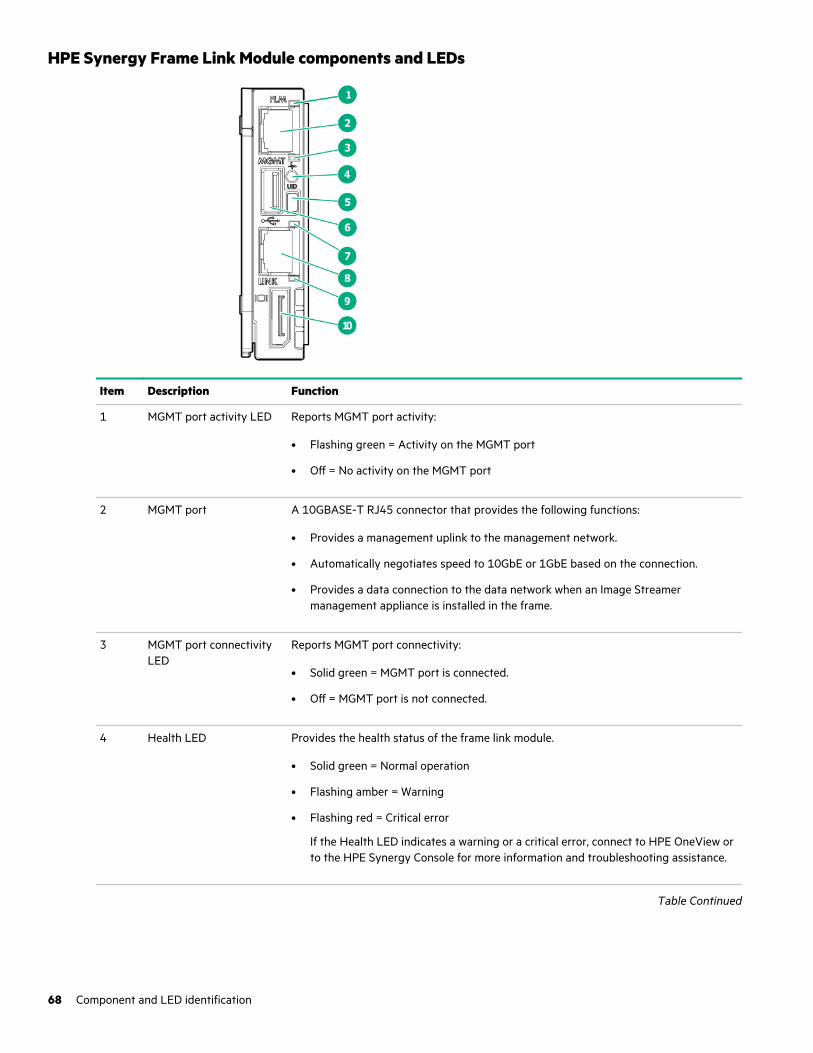
HPE Synergy Frame Link Module components and LEDs
Item Description Function
1 MGMT port activity LED Reports MGMT port activity:
• Flashing green = Activity on the MGMT port
• Off = No activity on the MGMT port
2 MGMT port A 10GBASE-T RJ45 connector that provides the following functions:
• Provides a management uplink to the management network.
• Automatically negotiates speed to 10GbE or 1GbE based on the connection.
• Provides a data connection to the data network when an Image Streamermanagement appliance is installed in the frame.
3 MGMT port connectivityLED
Reports MGMT port connectivity:
• Solid green = MGMT port is connected.
• Off = MGMT port is not connected.
4 Health LED Provides the health status of the frame link module.
• Solid green = Normal operation
• Flashing amber = Warning
• Flashing red = Critical error
If the Health LED indicates a warning or a critical error, connect to HPE OneView orto the HPE Synergy Console for more information and troubleshooting assistance.
Table Continued
68 Component and LED identification
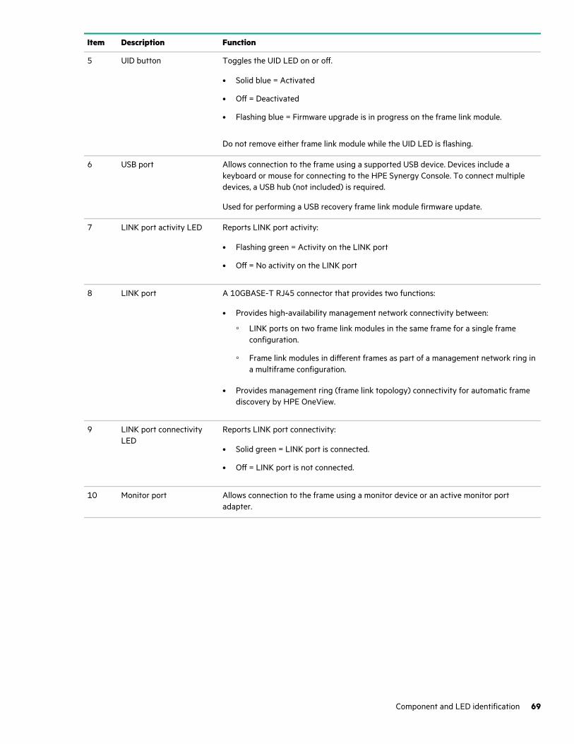
Item Description Function
5 UID button Toggles the UID LED on or off.
• Solid blue = Activated
• Off = Deactivated
• Flashing blue = Firmware upgrade is in progress on the frame link module.
Do not remove either frame link module while the UID LED is flashing.
6 USB port Allows connection to the frame using a supported USB device. Devices include akeyboard or mouse for connecting to the HPE Synergy Console. To connect multipledevices, a USB hub (not included) is required.
Used for performing a USB recovery frame link module firmware update.
7 LINK port activity LED Reports LINK port activity:
• Flashing green = Activity on the LINK port
• Off = No activity on the LINK port
8 LINK port A 10GBASE-T RJ45 connector that provides two functions:
• Provides high-availability management network connectivity between:
◦ LINK ports on two frame link modules in the same frame for a single frameconfiguration.
◦ Frame link modules in different frames as part of a management network ring ina multiframe configuration.
• Provides management ring (frame link topology) connectivity for automatic framediscovery by HPE OneView.
9 LINK port connectivityLED
Reports LINK port connectivity:
• Solid green = LINK port is connected.
• Off = LINK port is not connected.
10 Monitor port Allows connection to the frame using a monitor device or an active monitor portadapter.
Component and LED identification 69
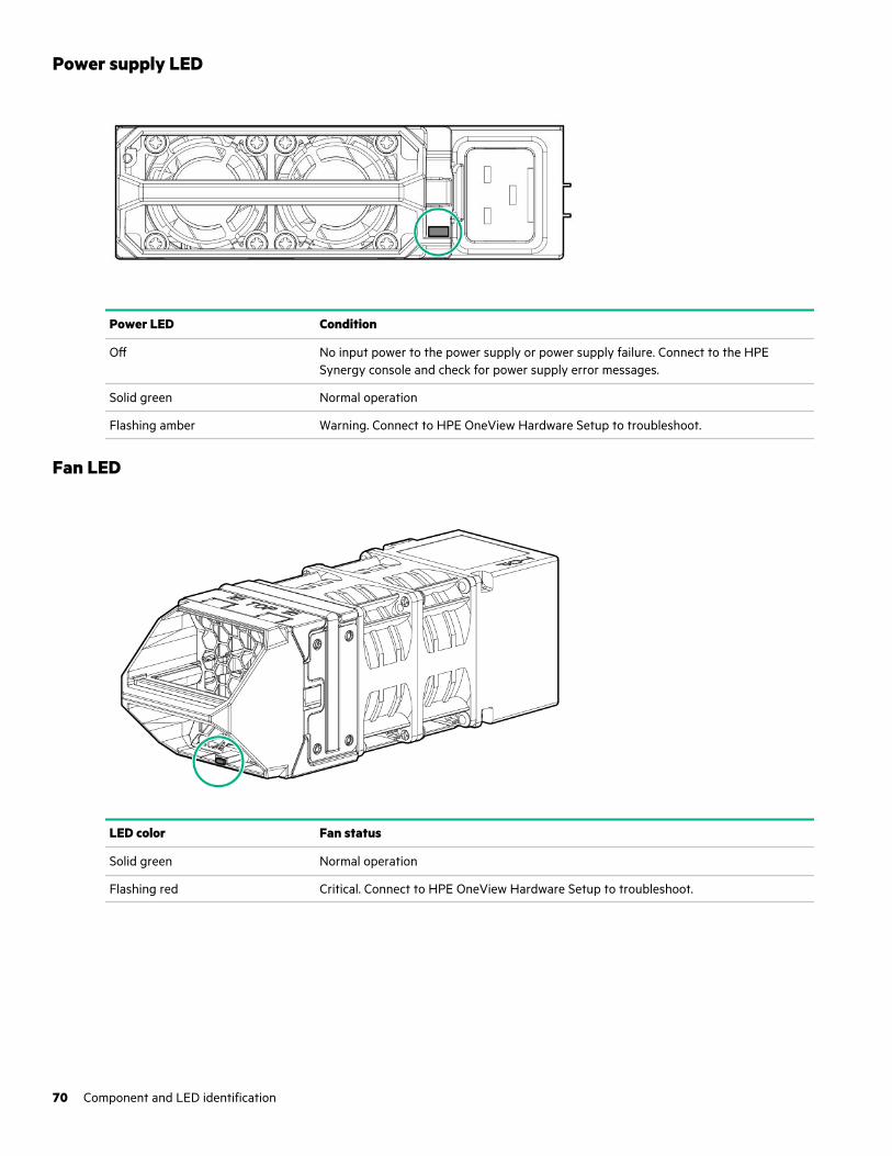
Power supply LED
Power LED Condition
Off No input power to the power supply or power supply failure. Connect to the HPESynergy console and check for power supply error messages.
Solid green Normal operation
Flashing amber Warning. Connect to HPE OneView Hardware Setup to troubleshoot.
Fan LED
LED color Fan status
Solid green Normal operation
Flashing red Critical. Connect to HPE OneView Hardware Setup to troubleshoot.
70 Component and LED identification
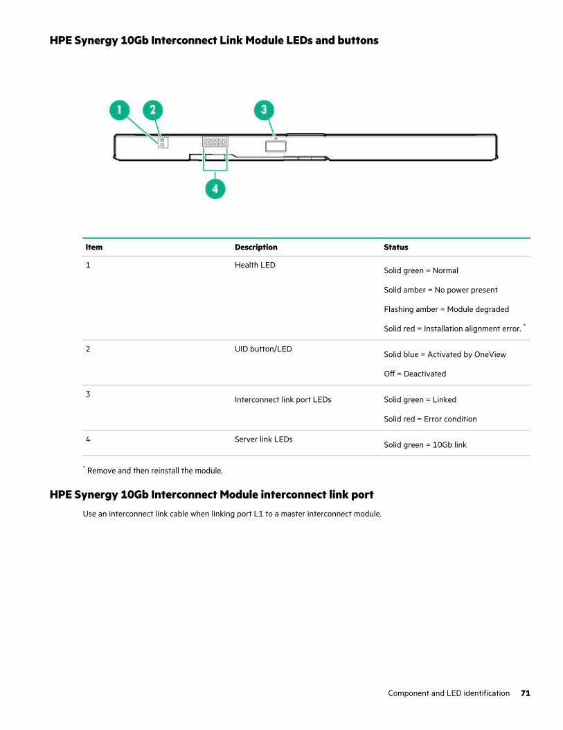
HPE Synergy 10Gb Interconnect Link Module LEDs and buttons
Item Description Status
1 Health LEDSolid green = Normal
Solid amber = No power present
Flashing amber = Module degraded
Solid red = Installation alignment error. *
2 UID button/LEDSolid blue = Activated by OneView
Off = Deactivated
3Interconnect link port LEDs Solid green = Linked
Solid red = Error condition
4 Server link LEDsSolid green = 10Gb link
* Remove and then reinstall the module.
HPE Synergy 10Gb Interconnect Module interconnect link portUse an interconnect link cable when linking port L1 to a master interconnect module.
Component and LED identification 71
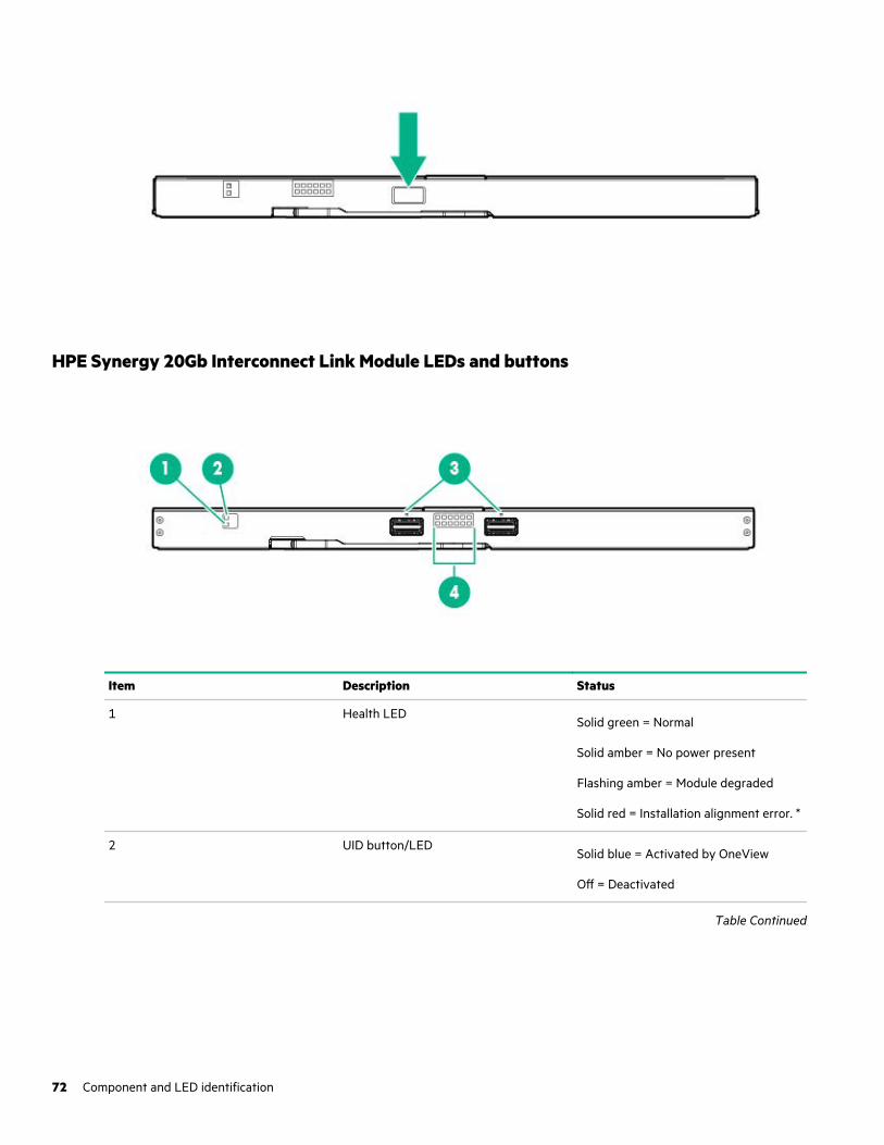
HPE Synergy 20Gb Interconnect Link Module LEDs and buttons
Item Description Status
1 Health LEDSolid green = Normal
Solid amber = No power present
Flashing amber = Module degraded
Solid red = Installation alignment error. *
2 UID button/LEDSolid blue = Activated by OneView
Off = Deactivated
Table Continued
72 Component and LED identification
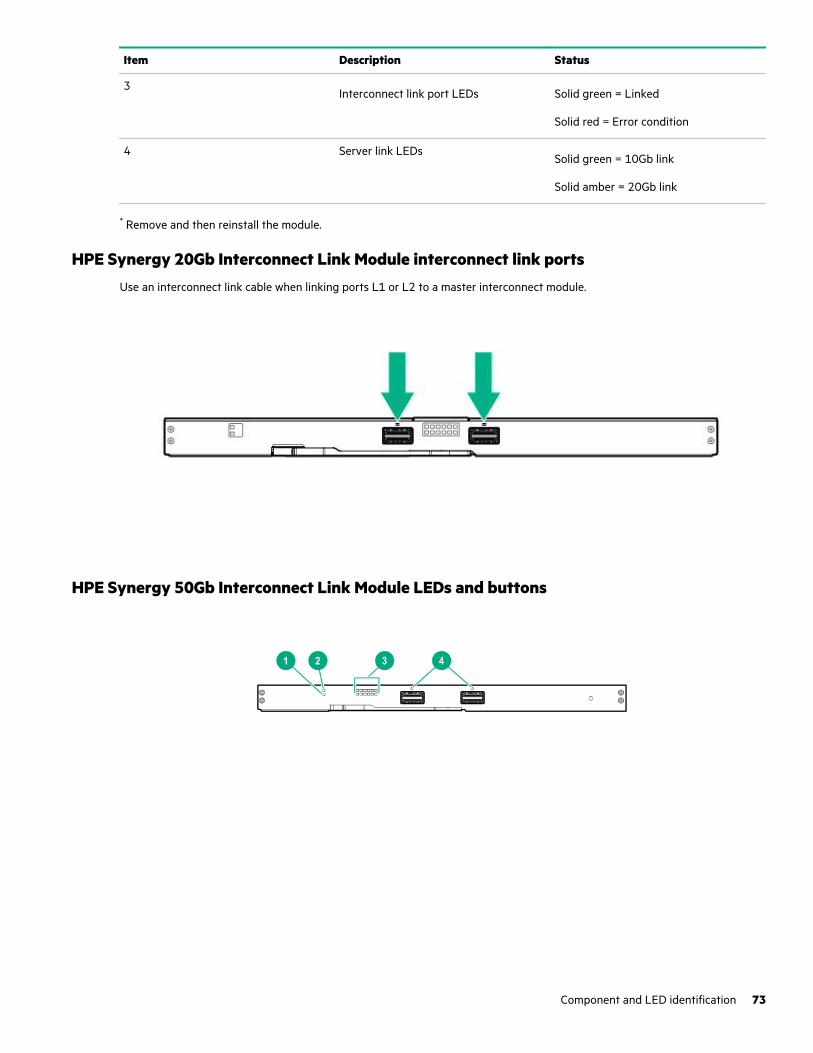
Item Description Status
3Interconnect link port LEDs Solid green = Linked
Solid red = Error condition
4 Server link LEDsSolid green = 10Gb link
Solid amber = 20Gb link
* Remove and then reinstall the module.
HPE Synergy 20Gb Interconnect Link Module interconnect link portsUse an interconnect link cable when linking ports L1 or L2 to a master interconnect module.
HPE Synergy 50Gb Interconnect Link Module LEDs and buttons
Component and LED identification 73
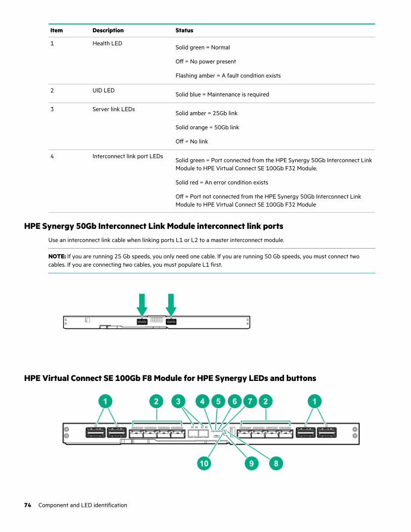
Item Description Status
1 Health LEDSolid green = Normal
Off = No power present
Flashing amber = A fault condition exists
2 UID LEDSolid blue = Maintenance is required
3 Server link LEDsSolid amber = 25Gb link
Solid orange = 50Gb link
Off = No link
4 Interconnect link port LEDsSolid green = Port connected from the HPE Synergy 50Gb Interconnect LinkModule to HPE Virtual Connect SE 100Gb F32 Module.
Solid red = An error condition exists
Off = Port not connected from the HPE Synergy 50Gb Interconnect LinkModule to HPE Virtual Connect SE 100Gb F32 Module
HPE Synergy 50Gb Interconnect Link Module interconnect link portsUse an interconnect link cable when linking ports L1 or L2 to a master interconnect module.
NOTE: If you are running 25 Gb speeds, you only need one cable. If you are running 50 Gb speeds, you must connect twocables. If you are connecting two cables, you must populate L1 first.
HPE Virtual Connect SE 100Gb F8 Module for HPE Synergy LEDs and buttons
74 Component and LED identification
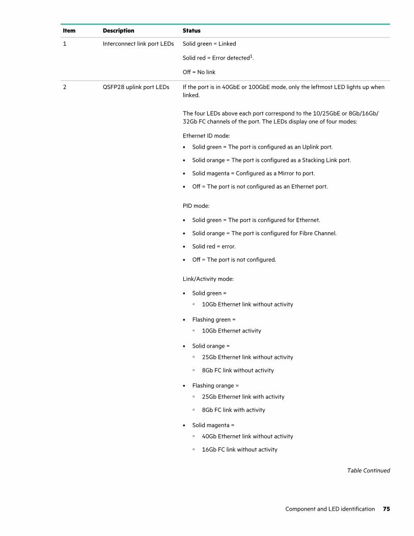
Item Description Status
1 Interconnect link port LEDs Solid green = Linked
Solid red = Error detected1.
Off = No link
2 QSFP28 uplink port LEDs If the port is in 40GbE or 100GbE mode, only the leftmost LED lights up whenlinked.
The four LEDs above each port correspond to the 10/25GbE or 8Gb/16Gb/32Gb FC channels of the port. The LEDs display one of four modes:
Ethernet ID mode:
• Solid green = The port is configured as an Uplink port.
• Solid orange = The port is configured as a Stacking Link port.
• Solid magenta = Configured as a Mirror to port.
• Off = The port is not configured as an Ethernet port.
PID mode:
• Solid green = The port is configured for Ethernet.
• Solid orange = The port is configured for Fibre Channel.
• Solid red = error.
• Off = The port is not configured.
Link/Activity mode:
• Solid green =
◦ 10Gb Ethernet link without activity
• Flashing green =
◦ 10Gb Ethernet activity
• Solid orange =
◦ 25Gb Ethernet link without activity
◦ 8Gb FC link without activity
• Flashing orange =
◦ 25Gb Ethernet link with activity
◦ 8Gb FC link with activity
• Solid magenta =
◦ 40Gb Ethernet link without activity
◦ 16Gb FC link without activity
Table Continued
Component and LED identification 75
Item Description Status
• Flashing magenta =
◦ 40Gb Ethernet link with activity
◦ 16Gb FC link with activity
• Solid cyan =
◦ 100Gb Ethernet link without activity
◦ 32Gb FC link without activity
• Flashing cyan =
◦ 100Gb Ethernet link with activity
◦ 32Gb FC link with activity
• Off = No link or not configured
Fibre Channel (FC) ID mode:
• Solid green = Logged into Attached Switch.
• Solid orange = Not logged into Attached Switch.
• Off = The port is not configured as an FC port.
To switch between the LED modes, press the Mode button.
3 SFP+ Image Streamer portLEDs
Left LED
Link/Activity mode:
• Off = No Link
• Solid green = Ethernet linked at 10Gb
PID:
• Off = Not configured
• Solid blue = Port ID
• Solid green = Configured for Ethernet
• Solid red = Error
Ethernet:
• Off = Not Ethernet
• Solid green = Configured for Ethernet
Fibre Channel:
Always off
Table Continued
76 Component and LED identification
Item Description Status
Right LED
Link/Activity mode:
• Off = No activity
• Flashing green = Activity at 10Gb
PID:
Always off
Ethernet:
Always off
Fibre Channel:
Always off
4 Fibre Channel (FC) modeLED
Solid green = FC mode is selected.
5 Ethernet mode LED Solid green = Ethernet mode is selected.
6 PID mode LED Solid green = PID mode is selected.
7 Link/Activity mode LED2 Solid green = Link/Activity mode is selected.
8 Health LED Solid green = Normal
Flashing amber = There is a fault condition
Flashing red = Critical fault detected
Solid red = No power present
9 Mode button Press and hold the Mode button for more than 5 seconds to reset.
Solid green = There are four LEDs that indicate the operating mode for thePort LEDs. The operating mode is selected by pressing the Mode button on thefront panel. The LED mode state determines which of the four Mode LEDs is lit.
10 UID LED Solid blue = Activated
Flashing blue = Firmware upgrade in progress
Off = Deactivated
1 See HPE OneView (http://www.hpe.com/info/oneview/docs)2 When illuminated, the QSFP28 port LEDs indicate the port operating states for each of the uplink ports in the selected mode.
Component and LED identification 77
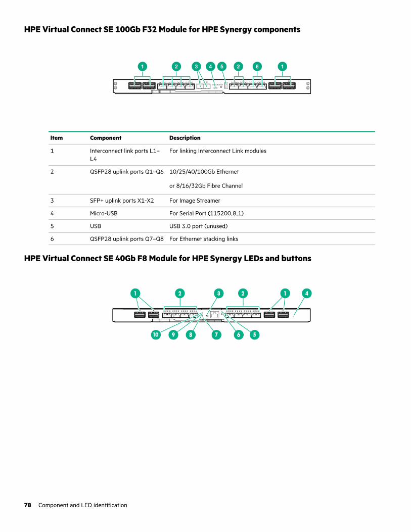
HPE Virtual Connect SE 100Gb F32 Module for HPE Synergy components
Item Component Description
1 Interconnect link ports L1–L4
For linking Interconnect Link modules
2 QSFP28 uplink ports Q1–Q6 10/25/40/100Gb Ethernet
or 8/16/32Gb Fibre Channel
3 SFP+ uplink ports X1-X2 For Image Streamer
4 Micro-USB For Serial Port (115200,8,1)
5 USB USB 3.0 port (unused)
6 QSFP28 uplink ports Q7–Q8 For Ethernet stacking links
HPE Virtual Connect SE 40Gb F8 Module for HPE Synergy LEDs and buttons
78 Component and LED identification
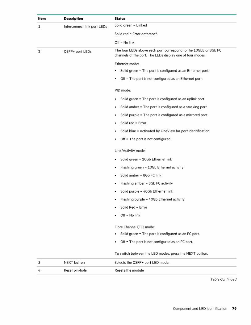
Item Description Status
1 Interconnect link port LEDs Solid green = Linked
Solid red = Error detected1.
Off = No link
2 QSFP+ port LEDs The four LEDs above each port correspond to the 10GbE or 8Gb FCchannels of the port. The LEDs display one of four modes:
Ethernet mode:
• Solid green = The port is configured as an Ethernet port.
• Off = The port is not configured as an Ethernet port.
PID mode:
• Solid green = The port is configured as an uplink port.
• Solid amber = The port is configured as a stacking port.
• Solid purple = The port is configured as a mirrored port.
• Solid red = Error.
• Solid blue = Activated by OneView for port identification.
• Off = The port is not configured.
Link/Activity mode:
• Solid green = 10Gb Ethernet link
• Flashing green = 10Gb Ethernet activity
• Solid amber = 8Gb FC link
• Flashing amber = 8Gb FC activity
• Solid purple = 40Gb Ethernet link
• Flashing purple = 40Gb Ethernet activity
• Solid Red = Error
• Off = No link
Fibre Channel (FC) mode:
• Solid green = The port is configured as an FC port.
• Off = The port is not configured as an FC port.
To switch between the LED modes, press the NEXT button.
3 NEXT button Selects the QSFP+ port LED mode.
4 Reset pin-hole Resets the module
Table Continued
Component and LED identification 79
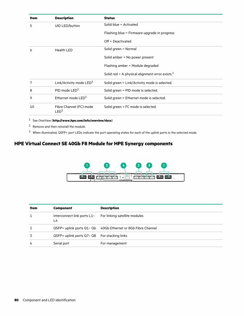
Item Description Status
5 UID LED/button Solid blue = Activated
Flashing blue = Firmware upgrade in progress
Off = Deactivated
6 Health LED Solid green = Normal
Solid amber = No power present
Flashing amber = Module degraded
Solid red = A physical alignment error exists.2
7 Link/Activity mode LED3 Solid green = Link/Activity mode is selected.
8 PID mode LED3 Solid green = PID mode is selected.
9 Ethernet mode LED3 Solid green = Ethernet mode is selected.
10 Fibre Channel (FC) modeLED3
Solid green = FC mode is selected.
1 See OneView (http://www.hpe.com/info/oneview/docs)2 Remove and then reinstall the module.3 When illuminated, QSFP+ port LEDs indicate the port operating states for each of the uplink ports in the selected mode.
HPE Virtual Connect SE 40Gb F8 Module for HPE Synergy components
Item Component Description
1 Interconnect link ports L1–L4
For linking satellite modules
2 QSFP+ uplink ports Q1– Q6 40Gb Ethernet or 8Gb Fibre Channel
3 QSFP+ uplink ports Q7– Q8 For stacking links
4 Serial port For management
80 Component and LED identification
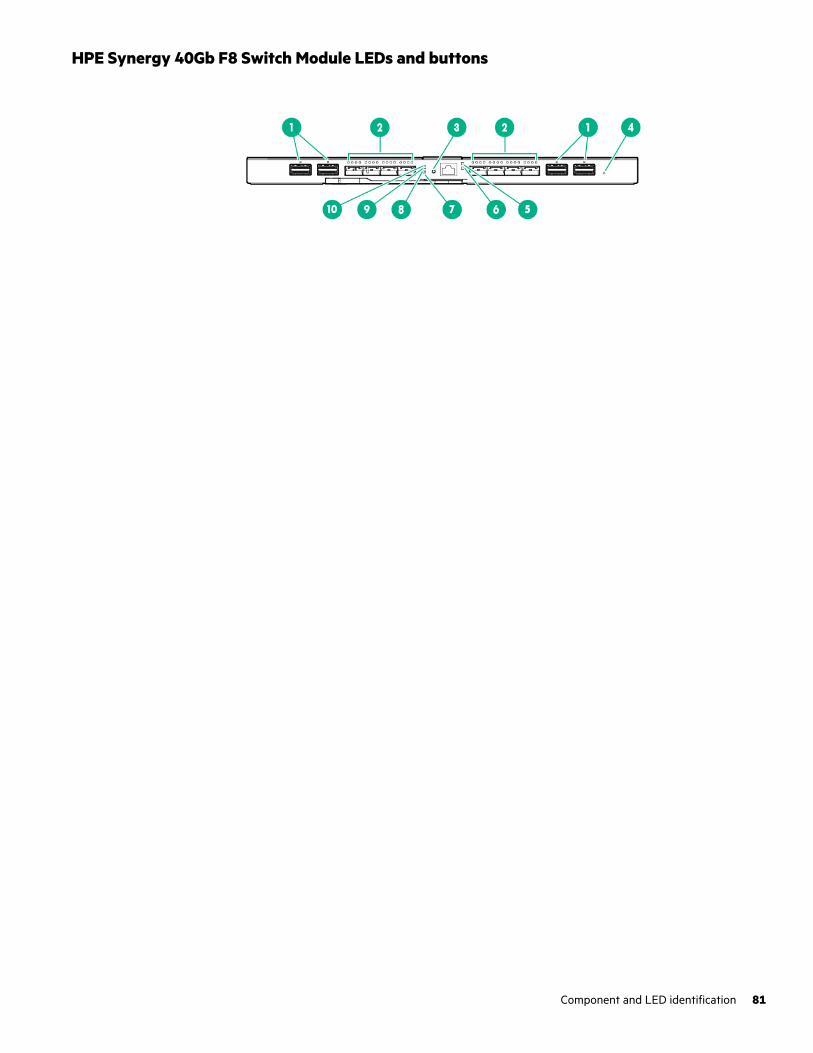
HPE Synergy 40Gb F8 Switch Module LEDs and buttons
Component and LED identification 81
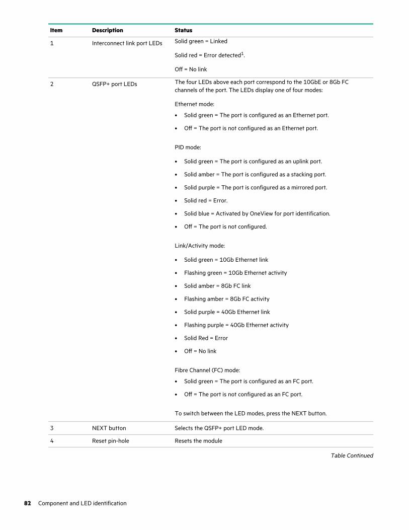
Item Description Status
1 Interconnect link port LEDs Solid green = Linked
Solid red = Error detected1.
Off = No link
2 QSFP+ port LEDs The four LEDs above each port correspond to the 10GbE or 8Gb FCchannels of the port. The LEDs display one of four modes:
Ethernet mode:
• Solid green = The port is configured as an Ethernet port.
• Off = The port is not configured as an Ethernet port.
PID mode:
• Solid green = The port is configured as an uplink port.
• Solid amber = The port is configured as a stacking port.
• Solid purple = The port is configured as a mirrored port.
• Solid red = Error.
• Solid blue = Activated by OneView for port identification.
• Off = The port is not configured.
Link/Activity mode:
• Solid green = 10Gb Ethernet link
• Flashing green = 10Gb Ethernet activity
• Solid amber = 8Gb FC link
• Flashing amber = 8Gb FC activity
• Solid purple = 40Gb Ethernet link
• Flashing purple = 40Gb Ethernet activity
• Solid Red = Error
• Off = No link
Fibre Channel (FC) mode:
• Solid green = The port is configured as an FC port.
• Off = The port is not configured as an FC port.
To switch between the LED modes, press the NEXT button.
3 NEXT button Selects the QSFP+ port LED mode.
4 Reset pin-hole Resets the module
Table Continued
82 Component and LED identification
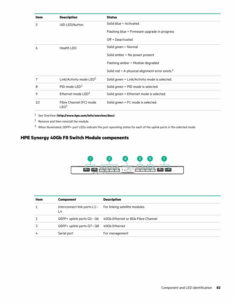
Item Description Status
5 UID LED/button Solid blue = Activated
Flashing blue = Firmware upgrade in progress
Off = Deactivated
6 Health LED Solid green = Normal
Solid amber = No power present
Flashing amber = Module degraded
Solid red = A physical alignment error exists.2
7 Link/Activity mode LED3 Solid green = Link/Activity mode is selected.
8 PID mode LED3 Solid green = PID mode is selected.
9 Ethernet mode LED3 Solid green = Ethernet mode is selected.
10 Fibre Channel (FC) modeLED3
Solid green = FC mode is selected.
1 See OneView (http://www.hpe.com/info/oneview/docs)2 Remove and then reinstall the module.3 When illuminated, QSFP+ port LEDs indicate the port operating states for each of the uplink ports in the selected mode.
HPE Synergy 40Gb F8 Switch Module components
Item Component Description
1 Interconnect link ports L1–L4
For linking satellite modules
2 QSFP+ uplink ports Q1– Q6 40Gb Ethernet or 8Gb Fibre Channel
3 QSFP+ uplink ports Q7– Q8 40Gb Ethernet
4 Serial port For management
Component and LED identification 83
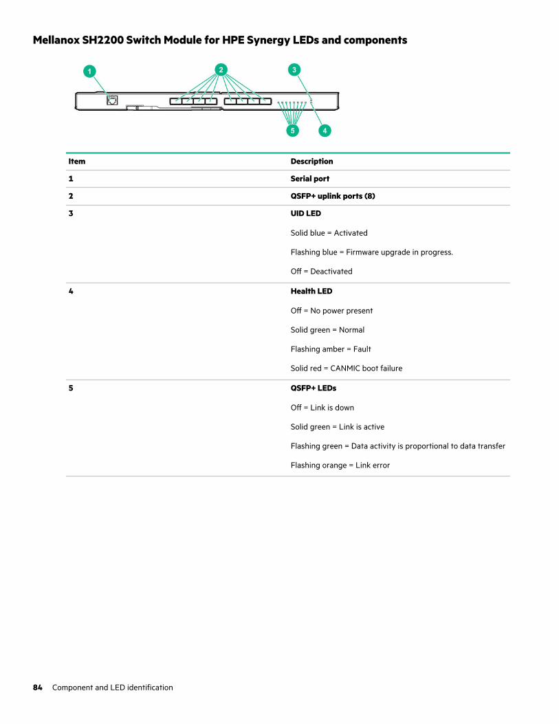
Mellanox SH2200 Switch Module for HPE Synergy LEDs and components
Item Description
1 Serial port
2 QSFP+ uplink ports (8)
3 UID LED
Solid blue = Activated
Flashing blue = Firmware upgrade in progress.
Off = Deactivated
4 Health LED
Off = No power present
Solid green = Normal
Flashing amber = Fault
Solid red = CANMIC boot failure
5 QSFP+ LEDs
Off = Link is down
Solid green = Link is active
Flashing green = Data activity is proportional to data transfer
Flashing orange = Link error
84 Component and LED identification

HPE Synergy Cabling
Depending on your HPE Synergy configuration, HPE Synergy requires various types of cabling. To assist with planning andcabling HPE Synergy, the HPE Synergy Cabling Guide provides cabling scenarios and diagrams.
• Management network cabling
Cabling the management network includes cabling the frame link module LINK ports together to form a management ring(frame link topology) and cabling two frame link module MGMT ports to the management network.
• HPE Synergy Image Streamer cabling
Cabling for HPE Synergy Image Streamer OS deployment includes management cabling, HPE Synergy Image Streamercabling, and interconnect cabling. HPE Synergy 12000 frames with HPE Synergy Image Streamer installed use each MGMTport in the frame for OS deployment. When HPE Synergy Image Streamer is installed in a frame, the MGMT ports areautomatically dedicated to OS deployment and cannot be used for management network connectivity.
• Interconnect module cabling
HPE Synergy supports a composable fabric that spans multiple frames and includes master interconnect modules(switches) and satellite modules (links).
• Power cabling
HPE Synergy power cabling includes cabling multiple frames for power feed redundant power, cabling power supplies forpower feed redundancy, and power cabling for both a single frame and multiple frame configurations.
• HPE Synergy Console cabling
Direct connections to the HPE Synergy Console are possible by connecting a laptop directly to a frame through the frontpanel or by connecting KVM to the frame link module.
For more information, see the HPE Synergy Cabling Guide at the Hewlett Packard Enterprise website (http://www.hpe.com/info/synergy-cabling-guide).
HPE Synergy Cabling 85
HPE Synergy documentation resources
The Hewlett Packard Enterprise Information Library (https://www.hpe.com/info/synergy-docs) provides a comprehensive,one stop location for all HPE Synergy documentation, including installation instructions, user guides, maintenance and serviceguides, best practices, and links to additional resources. The Library supports filtering to improve findability.
Document: Provides:
HPE Synergy Solution
Start Here Poster First-time setup procedure of an HPE Synergy solution, from hardwareinstallation to HPE OneView configuration.
Release Notes Release descriptions, new features, documentation updates, and issues andsuggested actions for products like HPE Synergy, HPE Synergy Image Streamer,and HPE OneView.
Migration Guide Information about migrating from HPE Synergy Composer to HPE SynergyComposer2 and from HPE Synergy Frame Link Module to HPE Synergy 4-portFrame Link Module.
Validating HPE Synergy appliancefirmware: Preparing an HPE Synergyappliance for first-time setup
Procedures for preparing an HPE Synergy appliance for initial use in a system.
Appliances User Guide Outlines appliance module management, configuration, and security.
Cabling Guide Cabling examples for management network, HPE Synergy Image Streamer,interconnects, and power.
Configuration and Compatibility Guide An overview of HPE Synergy management and fabric architecture, detailedhardware component identification, and configuration requirements forhardware components.
Frame Link Module User Guide Management, configuration, and security information for the HPE Synergy 4-Port Frame Link Module, HPE Synergy Frame Link Module, and HPE SynergyManagement Console.
Power Management Overview Guide Additional details on how HPE Synergy manages power usage in an HPESynergy 12000 Frame.
Troubleshooting Guide Information for resolving common problems and courses of action for faultisolation and identification, issue resolution, and maintenance.
Error Message Guide Information for resolving issues associated with specific error messages.
Documentation Map A descriptive map to filter and locate the HPE Synergy documentation you need.
Glossary Terminology, descriptions, and drawings to provide an understanding of theproduct and to help familiarize with the HPE Synergy ecosystem.
HPE Synergy Image Streamer
Deployment workflow Interactively describes the various steps involved in setting up HPE SynergyImage Streamer for OS deployment and has pointers to the different documentsthat contain detailed instructions on the steps.
Support Matrix The latest software and firmware requirements, supported hardware, andconfiguration maximums for HPE Synergy Image Streamer.
Table Continued
86 HPE Synergy documentation resources
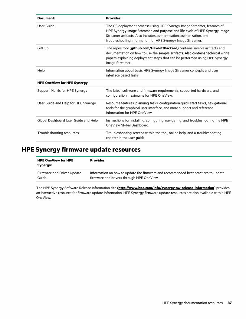
Document: Provides:
User Guide The OS deployment process using HPE Synergy Image Streamer, features ofHPE Synergy Image Streamer, and purpose and life cycle of HPE Synergy ImageStreamer artifacts. Also includes authentication, authorization, andtroubleshooting information for HPE Synergy Image Streamer.
GitHub The repository (github.com/HewlettPackard) contains sample artifacts anddocumentation on how to use the sample artifacts. Also contains technical whitepapers explaining deployment steps that can be performed using HPE SynergyImage Streamer.
Help Information about basic HPE Synergy Image Streamer concepts and userinterface based tasks.
HPE OneView for HPE Synergy
Support Matrix for HPE Synergy The latest software and firmware requirements, supported hardware, andconfiguration maximums for HPE OneView.
User Guide and Help for HPE Synergy Resource features, planning tasks, configuration quick start tasks, navigationaltools for the graphical user interface, and more support and referenceinformation for HPE OneView.
Global Dashboard User Guide and Help Instructions for installing, configuring, navigating, and troubleshooting the HPEOneView Global Dashboard.
Troubleshooting resources Troubleshooting screens within the tool, online help, and a troubleshootingchapter in the user guide.
HPE Synergy firmware update resourcesHPE OneView for HPESynergy:
Provides:
Firmware and Driver UpdateGuide
Information on how to update the firmware and recommended best practices to updatefirmware and drivers through HPE OneView.
The HPE Synergy Software Release Information site (http://www.hpe.com/info/synergy-sw-release-information) providesan interactive resource for firmware update information. HPE Synergy firmware update resources are also available within HPEOneView.
HPE Synergy documentation resources 87
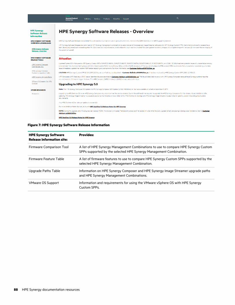
Figure 7: HPE Synergy Software Release Information
HPE Synergy SoftwareRelease Information site:
Provides:
Firmware Comparison Tool A list of HPE Synergy Management Combinations to use to compare HPE Synergy CustomSPPs supported by the selected HPE Synergy Management Combination.
Firmware Feature Table A list of firmware features to use to compare HPE Synergy Custom SPPs supported by theselected HPE Synergy Management Combination.
Upgrade Paths Table Information on HPE Synergy Composer and HPE Synergy Image Streamer upgrade pathsand HPE Synergy Management Combinations.
VMware OS Support Information and requirements for using the VMware vSphere OS with HPE SynergyCustom SPPs.
88 HPE Synergy documentation resources
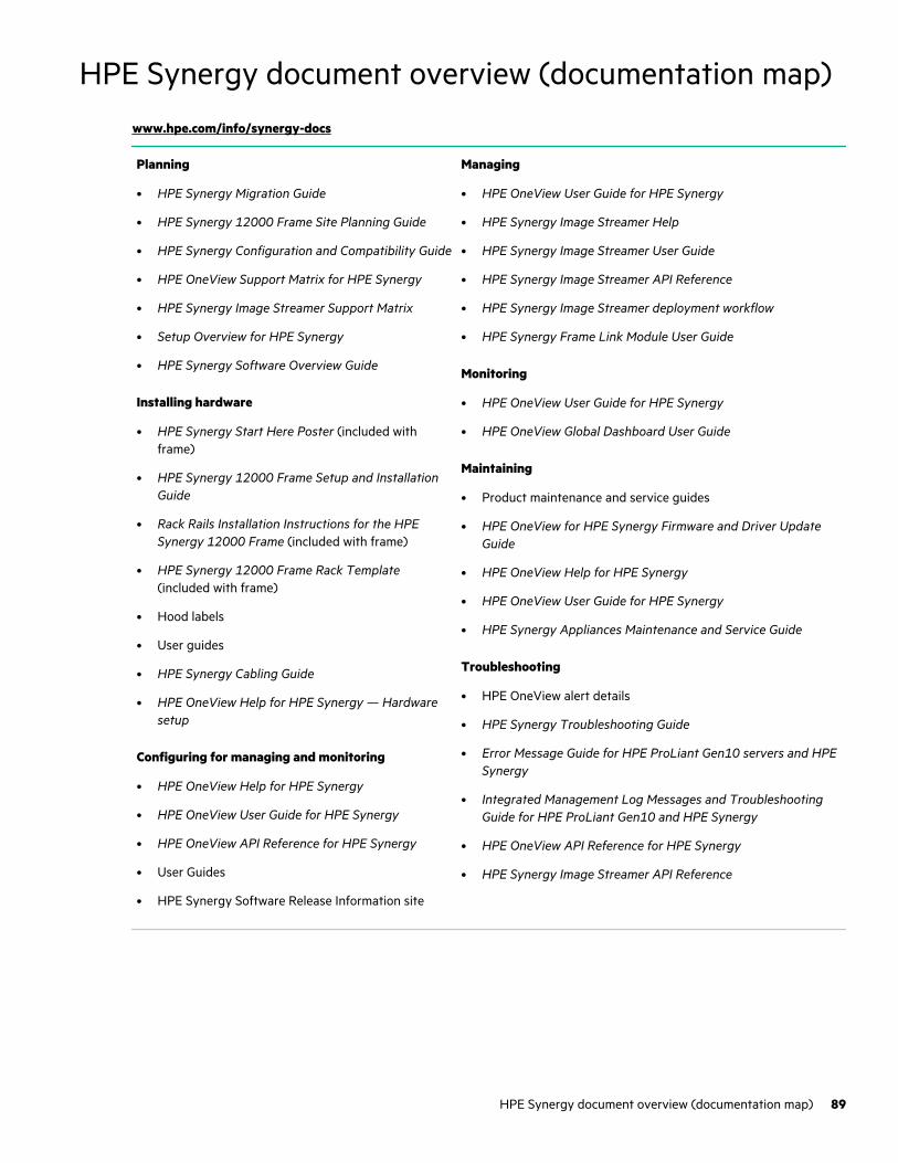
HPE Synergy document overview (documentation map)
www.hpe.com/info/synergy-docs
Planning
• HPE Synergy Migration Guide
• HPE Synergy 12000 Frame Site Planning Guide
• HPE Synergy Configuration and Compatibility Guide
• HPE OneView Support Matrix for HPE Synergy
• HPE Synergy Image Streamer Support Matrix
• Setup Overview for HPE Synergy
• HPE Synergy Software Overview Guide
Installing hardware
• HPE Synergy Start Here Poster (included withframe)
• HPE Synergy 12000 Frame Setup and InstallationGuide
• Rack Rails Installation Instructions for the HPESynergy 12000 Frame (included with frame)
• HPE Synergy 12000 Frame Rack Template(included with frame)
• Hood labels
• User guides
• HPE Synergy Cabling Guide
• HPE OneView Help for HPE Synergy — Hardwaresetup
Configuring for managing and monitoring
• HPE OneView Help for HPE Synergy
• HPE OneView User Guide for HPE Synergy
• HPE OneView API Reference for HPE Synergy
• User Guides
• HPE Synergy Software Release Information site
Managing
• HPE OneView User Guide for HPE Synergy
• HPE Synergy Image Streamer Help
• HPE Synergy Image Streamer User Guide
• HPE Synergy Image Streamer API Reference
• HPE Synergy Image Streamer deployment workflow
• HPE Synergy Frame Link Module User Guide
Monitoring
• HPE OneView User Guide for HPE Synergy
• HPE OneView Global Dashboard User Guide
Maintaining
• Product maintenance and service guides
• HPE OneView for HPE Synergy Firmware and Driver UpdateGuide
• HPE OneView Help for HPE Synergy
• HPE OneView User Guide for HPE Synergy
• HPE Synergy Appliances Maintenance and Service Guide
Troubleshooting
• HPE OneView alert details
• HPE Synergy Troubleshooting Guide
• Error Message Guide for HPE ProLiant Gen10 servers and HPESynergy
• Integrated Management Log Messages and TroubleshootingGuide for HPE ProLiant Gen10 and HPE Synergy
• HPE OneView API Reference for HPE Synergy
• HPE Synergy Image Streamer API Reference
HPE Synergy document overview (documentation map) 89
Specifications
HPE Synergy QuickSpecsHPE Synergy has system specifications as well as individual product and component specifications. For complete specificationinformation, see the HPE Synergy and individual HPE Synergy product QuickSpecs on the Hewlett Packard Enterprise website(www.hpe.com/info/qs).
90 Specifications

WebsitesGeneral websites
Hewlett Packard Enterprise Information Library
www.hpe.com/info/EIL
Single Point of Connectivity Knowledge (SPOCK) Storage compatibility matrix
www.hpe.com/storage/spock
Storage white papers and analyst reports
www.hpe.com/storage/whitepapers
For additional websites, see Support and other resources.
Websites 91
Support and other resources
Accessing Hewlett Packard Enterprise Support
• For live assistance, go to the Contact Hewlett Packard Enterprise Worldwide website:
http://www.hpe.com/info/assistance
• To access documentation and support services, go to the Hewlett Packard Enterprise Support Center website:
http://www.hpe.com/support/hpesc
Information to collect
• Technical support registration number (if applicable)
• Product name, model or version, and serial number
• Operating system name and version
• Firmware version
• Error messages
• Product-specific reports and logs
• Add-on products or components
• Third-party products or components
Accessing updates
• Some software products provide a mechanism for accessing software updates through the product interface. Review yourproduct documentation to identify the recommended software update method.
• To download product updates:
Hewlett Packard Enterprise Support Center
www.hpe.com/support/hpesc
Hewlett Packard Enterprise Support Center: Software downloads
www.hpe.com/support/downloads
Software Depot
www.hpe.com/support/softwaredepot
• To subscribe to eNewsletters and alerts:
www.hpe.com/support/e-updates
• To view and update your entitlements, and to link your contracts and warranties with your profile, go to the HewlettPackard Enterprise Support Center More Information on Access to Support Materials page:
www.hpe.com/support/AccessToSupportMaterials
IMPORTANT: Access to some updates might require product entitlement when accessed through the Hewlett PackardEnterprise Support Center. You must have an HPE Passport set up with relevant entitlements.
92 Support and other resources

Customer self repairHewlett Packard Enterprise customer self repair (CSR) programs allow you to repair your product. If a CSR part needs to bereplaced, it will be shipped directly to you so that you can install it at your convenience. Some parts do not qualify for CSR.Your Hewlett Packard Enterprise authorized service provider will determine whether a repair can be accomplished by CSR.
For more information about CSR, contact your local service provider or go to the CSR website:
http://www.hpe.com/support/selfrepair
Remote supportRemote support is available with supported devices as part of your warranty or contractual support agreement. It providesintelligent event diagnosis, and automatic, secure submission of hardware event notifications to Hewlett Packard Enterprise,which will initiate a fast and accurate resolution based on your product's service level. Hewlett Packard Enterprise stronglyrecommends that you register your device for remote support.
If your product includes additional remote support details, use search to locate that information.
Remote support and Proactive Care information
HPE Get Connected
www.hpe.com/services/getconnected
HPE Proactive Care services
www.hpe.com/services/proactivecare
HPE Datacenter Care services
www.hpe.com/services/datacentercare
HPE Proactive Care service: Supported products list
www.hpe.com/services/proactivecaresupportedproducts
HPE Proactive Care advanced service: Supported products list
www.hpe.com/services/proactivecareadvancedsupportedproducts
Proactive Care customer information
Proactive Care central
www.hpe.com/services/proactivecarecentral
Proactive Care service activation
www.hpe.com/services/proactivecarecentralgetstarted
Warranty informationTo view the warranty information for your product, see the links provided below:
HPE ProLiant and IA-32 Servers and Options
www.hpe.com/support/ProLiantServers-Warranties
HPE Enterprise and Cloudline Servers
www.hpe.com/support/EnterpriseServers-Warranties
HPE Storage Products
www.hpe.com/support/Storage-Warranties
HPE Networking Products
www.hpe.com/support/Networking-Warranties
Regulatory informationTo view the regulatory information for your product, view the Safety and Compliance Information for Server, Storage, Power,Networking, and Rack Products, available at the Hewlett Packard Enterprise Support Center:
Support and other resources 93

www.hpe.com/support/Safety-Compliance-EnterpriseProducts
Additional regulatory information
Hewlett Packard Enterprise is committed to providing our customers with information about the chemical substances in ourproducts as needed to comply with legal requirements such as REACH (Regulation EC No 1907/2006 of the EuropeanParliament and the Council). A chemical information report for this product can be found at:
www.hpe.com/info/reach
For Hewlett Packard Enterprise product environmental and safety information and compliance data, including RoHS andREACH, see:
www.hpe.com/info/ecodata
For Hewlett Packard Enterprise environmental information, including company programs, product recycling, and energyefficiency, see:
www.hpe.com/info/environment
Documentation feedbackHewlett Packard Enterprise is committed to providing documentation that meets your needs. To help us improve thedocumentation, send any errors, suggestions, or comments to Documentation Feedback ([email protected]). Whensubmitting your feedback, include the document title, part number, edition, and publication date located on the front cover ofthe document. For online help content, include the product name, product version, help edition, and publication date located onthe legal notices page.
94 Support and other resources