Embed Size (px)
Citation preview

HPE 3PAR StoreServ 8000 StorageInstallation Guide
AbstractThis guide is designed to instruct qualified technicians who are authorized to install the HPE 3PAR StoreServ 8000 Storagesystem and associated hardware components.
Part Number: QL226-99104Published: May 2016

© Copyright 2015, 2016 Hewlett Packard Enterprise Development LP
The information contained herein is subject to change without notice. The only warranties for Hewlett Packard Enterprise products and servicesare set forth in the express warranty statements accompanying such products and services. Nothing herein should be construed as constitutingan additional warranty. Hewlett Packard Enterprise shall not be liable for technical or editorial errors or omissions contained herein.
Confidential computer software. Valid license from Hewlett Packard Enterprise required for possession, use, or copying. Consistent with FAR12.211 and 12.212, Commercial Computer Software, Computer Software Documentation, and Technical Data for Commercial Items are licensedto the U.S. Government under vendor's standard commercial license.
Links to third-party websites take you outside the Hewlett Packard Enterprise website. Hewlett Packard Enterprise has no control over and is notresponsible for information outside the Hewlett Packard Enterprise website.
Acknowledgments
Microsoft® and Windows® are either registered trademarks or trademarks of Microsoft Corporation in the United States and/or other countries.
Apple® and Mac OS® are trademarks of Apple Incorporated.
Mozilla® and Firefox® are trademarks of Mozilla Incorporated.
VMware®, VMware® vCenter™, and VMware vSphere® are registered trademarks or trademarks of VMware, Inc. in the United States and/or
other jurisdictions.

Contents1 General Site Planning..........................................................................................7
Pre-Installation Planning.......................................................................................................................7Shipping Containers.............................................................................................................................9Acclimatization......................................................................................................................................9
2 Getting Started..................................................................................................10Tools...................................................................................................................................................10Precautions.........................................................................................................................................10
Preventing Electrostatic Discharge—Precautions.........................................................................11Rack Installation—Precautions.....................................................................................................12
Inspecting the Packaging....................................................................................................................12Redeeming and Registering HPE 3PAR Licenses.............................................................................12System Installation Options................................................................................................................13System Hardware Installation Checklist.............................................................................................13
3 Identifying System Components and Numbering..............................................14Bezel...................................................................................................................................................14
Bezel LEDs....................................................................................................................................14Controller Node Enclosures................................................................................................................15Controller Nodes.................................................................................................................................15
Node Numbering...........................................................................................................................16Node Ports.....................................................................................................................................17
Ethernet Port LEDs..................................................................................................................18FC Port LEDs...........................................................................................................................19SAS Ports LEDs.......................................................................................................................20Cluster Interconnect Link Ports LEDs......................................................................................21PCI-HBA Adapters Ports..........................................................................................................22PCI-HBA adapters LEDs..........................................................................................................25
4-port 16 Gb FC adapter LEDs...........................................................................................252-port 10 Gb iSCSI/FCoE Converged Network Adapter (CNA) LEDs................................252-port 10 Gb Ethernet NIC adapter LEDs...........................................................................264-port 1 Gb NIC adapter LEDs............................................................................................26
Node LEDs....................................................................................................................................27Installing Enclosures...........................................................................................................................28
Drive Enclosure Numbering...........................................................................................................28Drives..................................................................................................................................................29
Drive LEDs....................................................................................................................................30I/O Module..........................................................................................................................................31
I/O Module LEDs...........................................................................................................................31I/O Module Numbering..................................................................................................................32SAS Ports LEDs............................................................................................................................33
Power Cooling Modules......................................................................................................................34764 W PCM LEDs—Node Enclosure............................................................................................35764 W PCM Numbering—Node Enclosure...................................................................................36580 W PCM LEDs—Drive Enclosure............................................................................................37580 W PCM LEDs—Drive Enclosure............................................................................................38
Power Distribution Units.....................................................................................................................39Service Processor...............................................................................................................................39
Service Processor LEDs................................................................................................................404 Power Distribution Unit Installation....................................................................42
Safety and Regulatory Compliance....................................................................................................42Important Power Safety Precautions.............................................................................................42
Required Tools....................................................................................................................................43
Contents 3

Recommended PDU Configurations...................................................................................................44Installing PDUs...................................................................................................................................46Installing 1U and 0U PDUs.................................................................................................................50Securing Cable Retention Bracket......................................................................................................54
5 Hewlett Packard Enterprise Factory-Integrated System Setup.........................55Unpacking the Cabinet.......................................................................................................................55Positioning the Cabinet.......................................................................................................................55
Stabilizing Cabinet.........................................................................................................................55Cabling Verification.............................................................................................................................56Cable Restraint Shipping Brackets installation and removal..............................................................56
Installing Cable Restraint Shipping Brackets................................................................................56Removing Cable Restraint Shipping Brackets..............................................................................58
6 System Component Installation in Existing Rack..............................................59Unpacking Enclosures........................................................................................................................59Rail Kit Installation..............................................................................................................................59
Installing a 2U Rail Shelf...............................................................................................................61Installing a 4U Rail Shelf...............................................................................................................61
Enclosures Installation........................................................................................................................63Installing Enclosures......................................................................................................................63
Drives Installation...............................................................................................................................65SFF 2.5-inch drive—Allocating and Loading Guidelines...............................................................65
Best Practices—SFF Drive Allocating and Loading Guidelines...............................................66Avoid Practices—SFF Drive Allocating and Loading Guidelines.............................................66
Installing SFF 2.5-inch Drives........................................................................................................68LFF 3.5-inch drive—Allocating and Loading Guidelines...............................................................68
Best Practices—LFF Drive Allocating and Loading Guidelines...............................................69Avoid Practices—LFF Drive Allocating and Loading Guidelines..............................................70
Installing LFF 3.5-inch Drives........................................................................................................71Service Processor Installation............................................................................................................72
Installing SP Rail Kit and Service Processor.................................................................................747 System Cabling.................................................................................................79
Cabling Controller Nodes—4-Node systems......................................................................................79Host/Ethernet Cables....................................................................................................................80
Cabling Expansion Cabinets...............................................................................................................80Cabling the Service Processor...........................................................................................................81Cabling Power to the System.............................................................................................................81
Cabling Power Distribution Units...................................................................................................82Cabling Power Strips.....................................................................................................................82
8 System Setup Verification..................................................................................83Verifying Power Connections..............................................................................................................83Repositioning the System...................................................................................................................83Acclimating the System......................................................................................................................84
9 System Powering On and LED Status Verification............................................85Powering On the System....................................................................................................................85Verifying LED Status...........................................................................................................................85
10 System Installation Checklists.........................................................................86System Software Installation Checklist...............................................................................................86
11 Service Processor Initialization........................................................................90Connecting to a Virtual Service Processor with VMware ESXi...........................................................90
Prerequisites for Using a Virtual Service Processor......................................................................90Deploying Virtual Service Processor OVF File..............................................................................92Establishing Virtual Service Processor IP Address.......................................................................92
4 Contents

Option A: DHCP Network Environment....................................................................................92Option B: Non-DHCP Environment..........................................................................................93
Importing the HPE 3PAR VSP into Hyper-V.......................................................................................93System Requirements...................................................................................................................93Prerequisites for Using a VSP.......................................................................................................94Pre-Import Task Overview.............................................................................................................95Creating Virtual Network Adapters and Binding Them to the Physical Ethernet Adapters...........95Importing the VSP into Hyper-V Using a Virtual Hard Drive Package...........................................95
Connecting to a Physical Service Processor......................................................................................96Configuring Physical Service Processor IP Address.....................................................................96
12 Service Processor and System Setup.............................................................98HPE 3PAR SmartStart Prerequisites..................................................................................................98HPE 3PAR SmartStart System Setup.................................................................................................99HPE 3PAR Service Processor Setup Wizard...................................................................................100
SP Wizard Step 1—Welcome......................................................................................................101SP Wizard Step 2—Generate SP ID...........................................................................................102SP Wizard step 3—Networking...................................................................................................103SP Wizard Step 4—Remote Support..........................................................................................104SP Wizard Step 5—System Support Information........................................................................105SP Wizard Step 6—Time and Region.........................................................................................106SP Wizard Step 7—Change Passwords.....................................................................................106SP Wizard Step 8—Summary.....................................................................................................107SP Wizard Step 9—Applying Settings.........................................................................................107SP Wizard Step 10—Finish.........................................................................................................107
HPE 3PAR Storage System Setup Wizard.......................................................................................108System Wizard Step 1—Welcome..............................................................................................109System Wizard Step 2—Enter Serial Number.............................................................................110System Wizard Step 3—Verify Storage System..........................................................................111System Wizard Step 4—Configure Networking...........................................................................111System Wizard Step 5—Configuring Time..................................................................................111System Wizard Step 6—Change Password................................................................................111System Wizard Step 7—Verify Configuration..............................................................................112System Wizard Step 8—Progress...............................................................................................112System Wizard Step 9—Results.................................................................................................112
Post-Installation System Tasks.........................................................................................................112Identifying Physical Locations of Logical Cage Numbers............................................................113
13 Support and other resources.........................................................................114Accessing Hewlett Packard Enterprise Support...............................................................................114Accessing updates............................................................................................................................114Websites...........................................................................................................................................114Customer self repair.........................................................................................................................115Remote support................................................................................................................................115Documentation feedback..................................................................................................................115
A System Illustrated Contents List......................................................................116System Components........................................................................................................................116HPE 3PAR Service Processor..........................................................................................................118Rail Kits.............................................................................................................................................119Accessory Kits..................................................................................................................................120
B Enhancing Security with Data Encryption.......................................................121C Adding Drives and Expansion Drive Enclosures............................................122
Information About Drive Enclosure Upgrades..................................................................................122Drive Enclosure Expansion Limits....................................................................................................123
Contents 5

Information About Drive Upgrades...................................................................................................1233PAR StoreServ 8000 Storage 2.5-inch Drive Enclosure Drive Placement.....................................1243PAR StoreServ 8000 Storage 3.5-inch Drive Enclosure Drive Placement.....................................124Adding Drives...................................................................................................................................125Adding Expansion Drive Enclosures.................................................................................................126
D Installing HPE 3PAR Storage Software When HPE 3PAR SmartStart isUnavailable.........................................................................................................127
Manually Launching the HPE 3PAR Service Processor Setup Wizard............................................127Manually Launching the HPE 3PAR Storage System Setup Wizard................................................127Installing the HPE 3PAR StoreServ Management Console When HPE 3PAR SmartStart isUnavailable.......................................................................................................................................128
E Validating Remote Support.............................................................................129F Troubleshooting...............................................................................................130
Troubleshooting Duplicate IP Address Issues..................................................................................1303PAR StoreServ Storage Detection Issues......................................................................................130Remote Support Configuration Fails.................................................................................................131The Service Processor IP Setup Wizard Fails or Hangs..................................................................131
G System Deinstallation.....................................................................................133System Inventory..............................................................................................................................133Uninstalling the System....................................................................................................................134
H Warranty and regulatory information...............................................................138Warranty information.........................................................................................................................138Regulatory Information.....................................................................................................................138
Regulatory Model Numbers.........................................................................................................138Safety Precautions......................................................................................................................138
General Precautions..............................................................................................................138Symbols on Equipment..........................................................................................................139Precautions for Maintaining and Servicing Products..............................................................139Power Cords...........................................................................................................................140Batteries.................................................................................................................................141Power Supplies......................................................................................................................141
Environmental Notices.................................................................................................................141Waste Electrical and Electronic Equipment (WEEE) Statements..........................................141
Regulatory Compliance Notices..................................................................................................144United States of America.......................................................................................................144Canadian Class A Notice (Avis Canadien).............................................................................145European Union Notices........................................................................................................145Japan......................................................................................................................................145South Korea...........................................................................................................................146Taiwan....................................................................................................................................146Belarus Kazakhstan Russia marking.....................................................................................146
RoHS Material Content Declarations..........................................................................................148China RoHS Material Content Declaration.............................................................................148India RoHS Material Content Declaration..............................................................................148Turkey RoHS material content declaration.............................................................................148Ukraine RoHS material content declaration...........................................................................148
Glossary.............................................................................................................149Index...................................................................................................................150
6 Contents

1 General Site PlanningSuccessful installation of the HPE 3PAR StoreServ 8000 Storage system requires careful planningand supervision in collaboration with authorized Hewlett Packard Enterprise representatives.Proper planning will help provide for a more efficient installation and greater reliability, availability,and serviceability. The chapter includes general recommendations for physical planning and sitepreparation for the system installation.For more detailed site planning information, see the HPE 3PAR StoreServ 8000 Storage SitePlanning Manual go to:http://www.hpe.com/info/storage/docs
Pre-Installation PlanningNOTE: All pre-installation activities should be scheduled and completed before the equipmentis delivered.
When planning and preparing for the installation of a system, you assume the followingresponsibilities:
• Providing suitable space for unpacking, installing, and operating the system.
• Maintaining the proper environmental conditions for the system.
• Providing adequate power facilities for the system.
• Supplying the network connections and external cabling required by the system.
• Enabling the appropriate HPE 3PAR remote support strategy.
NOTE: Electronic equipment has special packing for shipping and receives special handlingduring transportation. Hewlett Packard Enterprise is responsible for the manufacturing environmentand packaging for shipping.
Environment—For optimal performance at a specific location, systems require controlledenvironmental conditions that can best be facilitated through raised flooring and under-floor airconditioning. It is the customer's responsibility to monitor this environment to ensure continuedconformance with the recommended environmental specifications.Power—Adequate power is necessary for the reliable functioning of electronic equipment andfor the safety of the customer's installation. The customer is responsible for procuring, installing,and maintaining adequate power to the equipment.For specific information concerning server-room environments and for input electrical power andgrounding requirements, see the HPE 3PAR StoreServ 8000 Storage Site Planning Manual athttp://www.hpe.com/info/storage/docsThe pre-installation process includes the following:• Hardware configuration planning, such as system component layout and drive allocation.
• Networking and cabling topics, such as system and SP network topologies, internal systemcabling configurations, and cabling of connected host computers.
Pre-Installation Planning 7

Prior to delivery and installation tasksPrior to the delivery and installation, complete the following site planning tasks :
• Prepare a preliminary layout of the subsystem installation.
• Review the power and the heating, ventilation, and air-conditioning (HVAC) requirements.
• Order any additional support equipment indicated by the power and HVAC review.
• Work with the appropriate Hewlett Packard Enterprise representative to ensure that allsystem units in the specified configuration and all cables of the required length have beenordered.
• Make a final layout of the installation and review the layout with your Hewlett PackardEnterprise representative.
• Select key personnel and arrange for training with your Hewlett PackardEnterprise representative.
• Verify that the electrical service wiring has been installed at the predetermined locationbefore installing the system. For detailed requirements, see the respective productspecifications.
• Verify that any additional support equipment is properly installed and operational.
Prior to installation tasksPrior to installation, review the packaging to verify that no tampering of the goods has occurred.When unpacking the equipment, verify that the delivered shipment of all the equipment is correct.Refer to the packing slip and the SKUs with the shipment.Complete the “System Hardware Installation Checklist” (page 13).Prepare the following checkpoints with your local sales representative or systems engineer:• Contact information for customer personnel and for Hewlett Packard Enterprise technical
sales, support, and service personnel• Implementation project plan
• Configuration information for the system to be installed, including system configurationdiagrams
• Shipping and delivery details and requirements
• Management workstation, SP, and network information
• Description of the environment
• Volume and RAID level planning information
• Additional notes and comments about installation
• Current support matrix
• System technical specifications
• Systems Acceptance Certificate
8 General Site Planning

Shipping ContainersA separate shipping container holds each system rack. The drive enclosure and controller nodeenclosure shipping containers hold a maximum of 24 drives. Examine the delivered package forobvious damage or signs of tampering and notify both Hewlett Packard Enterprise and the carrierof any issues.
Table 1 Shipping containers
ApproximateShipping WeightDimensions (Height x Width x Depth)Container
1606 lb (728 kg)(216.80 cm x 129.20 cm x 90 cm)85.35 in x 50.87 in x 35.43 inRack cratecontainer
33.8 lb (15.4 kg)(33.1 cm x 28 cm x 68.6 cm)13 in x 11 in x 27 inDrive enclosurecontainer
392 lb (177.8 kg)(96.5 cm x 73.6 cm x 86.4 cm)38 in x 29 in x 34 inDrive magazinecontainer
618 lb (280.3 kg)(76.2 cm x 88.9 cm x 114.3 cm)30 in x 35 in 45 inController nodeenclosurecontainer
When the equipment arrives, you must verify that there is enough room to unload and unpackthe system.The specific amount of space you will need to unpack the system is based on the dimensions ofthe container, the ramp, and the room required to access the system so that it can be moved toits placement destination.
NOTE: For more information about placement of the systems and reserving room for serviceaccess, see the HPE 3PAR StoreServ 8000 Storage Site Planning Manual athttp://www.hpe.com/info/storage/docs
AcclimatizationSystems are shipped or stored at extreme temperatures and might require time to adjust tooperating temperatures before startup. The maximum acceptable rate of temperature changefor a non-operating system is 36° F/hour (20° C/hour). The system requires time to acclimatizeto new environmental conditions before being powered on. During that time, it is possible toproceed with the physical installation of the system. However, the system might need at least 24hours to acclimatize to a new environment prior to completing the full system installation. Ifcondensation is present even after the 24-hour acclimatization period, it is necessary to wait untilall condensation has evaporated before completing the power-on sequence.
Shipping Containers 9

2 Getting StartedBefore you begin, read the following guidelines to help you complete the installation successfully.If you need assistance with the installation, contact Hewlett Packard Enterprise Support or seethe Hewlett Packard Enterprise Support website:Hewlett Packard Enterprise Support Center (http://www.hpe.com/support/hpesc)
Tools
CAUTION: Always wear an electrostatic discharge (ESD) wrist-grounding strap when installinga system hardware part.
The following tools are not required but can be useful, especially when unpacking or installingthe system:• ESD wrist-grounding strap
• ESD mat
• #1 and #2 Phillips screwdrivers
• T25 Torx toolbit
• 1/8 inch (3 mm) slotted screwdriver
• 3/16 inch (5 mm) slotted screwdriver
• Adjustable wrench
• Diagonal cutting pliers
PrecautionsTo avoid injury, data loss, and damage, observe the following general precautions when installingor servicing the system:• Using improper tools can result in damage to the system.
• Prepare an ESD work surface by placing an antistatic mat on the floor or on a table nearthe system. Attach the ground lead of the mat to an unpainted surface of the rack.
• Always use the wrist-grounding strap provided with the system. Attach the grounding strapclip directly to an unpainted surface of the rack.
• Avoid contact between electronic components and clothing, which can carry an electrostaticcharge.
• If applicable, ensure that all cables are properly labeled and easily identifiable before youremove a component.
• Observe local occupational safety requirements and guidelines for heavy equipment handling.
• Do not attempt to move a fully loaded equipment rack. Remove equipment from the rackbefore moving it.
• Use at least two people to safely unload the rack from the pallet.
10 Getting Started

Preventing Electrostatic Discharge—PrecautionsESD can damage electrostatic-sensitive devices and microcircuitry. Proper packaging andgrounding techniques are important precautions to prevent damage.To prevent electrostatic damage, observe the following precautions:• Transport products in electrostatic-safe containers, such as conductive tubes, bags, or boxes.
• Keep static-sensitive parts in their containers until they arrive at static-free workstations.
• Cover workstations with approved static-dissipating material. Use a wrist strap connectedto the work surface, and properly grounded (earthed) tools and equipment.
• Keep the work area free of nonconductive materials, such as ordinary plastic assembly aidsand foam packing.
• Ensure that you are always properly grounded (earthed) when touching a static-sensitivecomponent or assembly.
• Avoid touching pins, leads, and circuitry.
• Always place drives with the printed circuit board assembly-side down.
• Use conductive field service tools.
Precautions 11
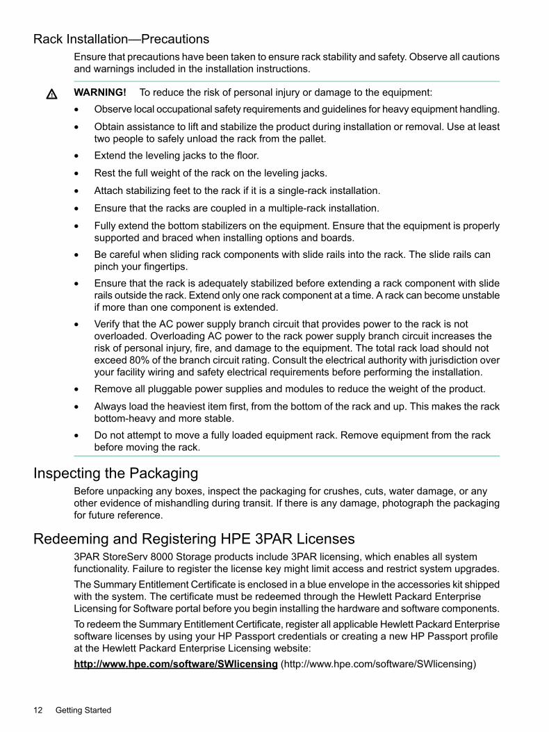
Rack Installation—PrecautionsEnsure that precautions have been taken to ensure rack stability and safety. Observe all cautionsand warnings included in the installation instructions.
WARNING! To reduce the risk of personal injury or damage to the equipment:• Observe local occupational safety requirements and guidelines for heavy equipment handling.
• Obtain assistance to lift and stabilize the product during installation or removal. Use at leasttwo people to safely unload the rack from the pallet.
• Extend the leveling jacks to the floor.
• Rest the full weight of the rack on the leveling jacks.
• Attach stabilizing feet to the rack if it is a single-rack installation.
• Ensure that the racks are coupled in a multiple-rack installation.
• Fully extend the bottom stabilizers on the equipment. Ensure that the equipment is properlysupported and braced when installing options and boards.
• Be careful when sliding rack components with slide rails into the rack. The slide rails canpinch your fingertips.
• Ensure that the rack is adequately stabilized before extending a rack component with sliderails outside the rack. Extend only one rack component at a time. A rack can become unstableif more than one component is extended.
• Verify that the AC power supply branch circuit that provides power to the rack is notoverloaded. Overloading AC power to the rack power supply branch circuit increases therisk of personal injury, fire, and damage to the equipment. The total rack load should notexceed 80% of the branch circuit rating. Consult the electrical authority with jurisdiction overyour facility wiring and safety electrical requirements before performing the installation.
• Remove all pluggable power supplies and modules to reduce the weight of the product.
• Always load the heaviest item first, from the bottom of the rack and up. This makes the rackbottom-heavy and more stable.
• Do not attempt to move a fully loaded equipment rack. Remove equipment from the rackbefore moving the rack.
Inspecting the PackagingBefore unpacking any boxes, inspect the packaging for crushes, cuts, water damage, or anyother evidence of mishandling during transit. If there is any damage, photograph the packagingfor future reference.
Redeeming and Registering HPE 3PAR Licenses3PAR StoreServ 8000 Storage products include 3PAR licensing, which enables all systemfunctionality. Failure to register the license key might limit access and restrict system upgrades.The Summary Entitlement Certificate is enclosed in a blue envelope in the accessories kit shippedwith the system. The certificate must be redeemed through the Hewlett Packard EnterpriseLicensing for Software portal before you begin installing the hardware and software components.To redeem the Summary Entitlement Certificate, register all applicable Hewlett Packard Enterprisesoftware licenses by using your HP Passport credentials or creating a new HP Passport profileat the Hewlett Packard Enterprise Licensing website:http://www.hpe.com/software/SWlicensing (http://www.hpe.com/software/SWlicensing)
12 Getting Started

For assistance with registering the Hewlett Packard Enterprise software licenses, see the HewlettPackard Enterprise Support website:Hewlett Packard Enterprise Support Center (http://www.hpe.com/support/hpesc)
System Installation OptionsThe following installation options are available and these options connect to the network in thesame way:• Installation of a Hewlett Packard Enterprise integrated rack—Components are installed
in a Hewlett Packard Enterprise rack and shipped. See “Hewlett PackardEnterprise Factory-Integrated System Setup” (page 55).
• Installation of system components in an existing rack—System components are shippedin separate packaging and are installed by a customer and/or authorized service personalin existing third-party racks or Hewlett Packard Enterprise racks. See “System ComponentInstallation in Existing Rack” (page 59).
For configuration specifications and installation requirements, see the HPE 3PAR StoreServ8000 Storage Site Planning Manual athttp://www.hpe.com/info/storage/docsFor information about supported hardware and software platforms, see the HPE Single Point ofConnectivity Knowledge (HPE SPOCK) website:HPE SPOCK (http://www.hpe.com/storage/spock)For supported versions of management, configuration, and host-based software, in the menu onthe left, under Software, click Array SW: 3PAR.
System Hardware Installation ChecklistBefore installing the system hardware components, verify that the environmental requirements,electrical requirements, and rack access in the HPE 3PAR StoreServ 8000 Storage Site PlanningManual have been met and that you have the following:
• Standard AC power
• Host computer with access to software, BIOS, drives, and HPE 3PAR OS
• FC HBA, FC host cable, and power cord
• Network access
• SP connectivity
• Tools
• Rail kits
• System and its components
System Installation Options 13

3 Identifying System Components and NumberingNOTE: The illustrations in this chapter are examples only and might not accurately representyour storage-system configuration.Due to the large number of prospective configurations, component placement and internal cablingis standardized to simplify installation and maintenance. System components are placed in therack according to the principles outlined in this chapter, and are numbered according to theirorder and location in the cabinet.
BezelBezel LEDs
Figure 1 Bezel LEDs location
Table 2 Bezel LEDs description
IndicatesStateAppearanceFunctionLED Icon
PowerOnGreenSystem Power1
No powerOff
Enclosure powered by the batteryOnAmberSystem Standby
FaultOnAmberModule Fault2
No faultOff
Fault—An issue exists with one or more drives withinthe enclosure. Inspect the LEDs on each drive todetermine the affected drive(s).
OnAmberDrive Status3
This LED applies only to drives.
No faultOff
14 Identifying System Components and Numbering

LED TroubleshootingPrior to running installation scripts, the numeric display located under the Drive Status LED mightnot display the proper numeric order in relation to their physical locations. The correct sequencewill be displayed after the installation script is completed.
Controller Node EnclosuresThe system includes the 3PAR StoreServ 8000 Series Storage Controller Node Enclosure:
• Holds up to 24 SFF 2.5-inch drives in a single horizontal row at the front of the nodeenclosure,
• Contains two 764 W (gold series) PCMs in the rear of the enclosure,
• Contains two controller nodes in the rear of the enclosure,
Controller NodesThe controller node is a system component that caches and manages data in a system andprovides hosts with a coherent, virtualized view of the system. The controller nodes are locatedin the rear of the controller node enclosure.The 3PAR StoreServ 8000 Storage servers contain either two controller nodes or four controllernodes:• 2-node system—Contains controller nodes 0 and 1 as shown in Figure 2 (page 16).
• 4-node system—Contains controller nodes 0 and 1 in the lower node enclosure and controllernodes 2 and 3 in the upper controller node enclosure as shown in Figure 3 (page 16).
Controller Node Enclosures 15

Node Numbering
Figure 2 2-node system numbering
Figure 3 4-node system numbering
16 Identifying System Components and Numbering

Node Ports
Figure 4 Node ports location
Table 3 Node ports description
DescriptionPort TypeSlotNumber
CalloutLabel
PCIe slot for optional host bus adapters (HBAs):PCI-HBASlot 21• 4-port 16 Gb FC Adapter
• 2-port 10 Gb iSCSI/FCoE Converged Network Adapter (CNA)
• 4-port 1 Gb NIC Adapter
• 2-port 10 Gb Ethernet Adapter
Two onboard 16 Gb FC ports used for connecting to host systems:FibreChannel
Slot 02• FC-1
• FC-2
MGMT-1: Gb Ethernet port used to connect to the storage array managementinterfaces.
Ethernet3
RC-1: Onboard Gb Ethernet port used for remote copy or file persona.EthernetSlot 34
Two onboard 12 Gb SAS ports used with SAS cables for connecting to thedrive enclosures and I/O modules:
SASSlot 15
• DP-1
• DP-2
Two Cluster Interconnect Link ports used with 4-directional interconnect linkcables that connect the controller nodes
ClusterInterconnectLink
6
NOTE: Cluster Interconnect Link ports only used with 4-node systems
Serial/Console port only for Hewlett Packard Enterprise internal use.MFG(serial/consoleport)
7
Controller Nodes 17

Ethernet Port LEDsThe controller node has two built-in Ethernet ports:• MGMT—Eth0 port provides connection to the public network.
• RC-1—Designated port for remote-copy functionality.
Figure 5 Ethernet LEDs location
Table 4 Ethernet LEDs description
IndicatesStateAppearanceLED Function
1 GbE LinkOnGreenLink UpSpeed
1
100 Mb LinkOnAmber
No link established or 10 Mb LinkOff
No link activityOnGreenActivity2
Link activityFlashing
No link establishedOff
18 Identifying System Components and Numbering

FC Port LEDsThe controller node has two onboard FC ports; each includes two LEDs. The arrow head-shapedLEDs point to the port they are associated with.
NOTE: Incorrectly configured cables result in illuminated amber LEDs.
Port position is displayed as Node:Slot:Port (N:S:P) in the SSMC.
Slot:PortPort
N:0:1FC-1N = Node number
N:0:2FC-2N = Node number
Figure 6 FC ports LEDs location
Table 5 FC Ports LEDs description
IndicatesStateAppearanceLEDFunction
Wake up failure (dead device) or power not appliedOffNo lightAll ports
Not connectedOffAmberPort Speed1
Connected at 8 Gb/s3 FastFlashes
Connected at 16 Gb/s4 FastFlashes
Normal/Connected – link upOnGreenLink Status2
Link down or not connectedFlashing
Controller Nodes 19

SAS Ports LEDsThe controller node has two SAS ports (DP-1 and DP-2) and each includes two LEDs.
Figure 7 SAS ports LEDs location
Table 6 SAS ports LEDs description
IndicatesStateAppearanceFunctionIcon
No link activityOnGreenActivity
Link activityFlashing
No link establishedOff
FaultOnAmberFault
Locate command issuedFlashing
Normal operationOff
20 Identifying System Components and Numbering

Cluster Interconnect Link Ports LEDsThe controller node has two Cluster Interconnect Link ports and each includes two LEDs.
NOTE:• 4-node systems—Cluster Interconnect Link ports are used to connect nodes together.
• 2-node system—Cluster Interconnect Link ports are not used and LEDs should always beoff.
Figure 8 Cluster Interconnect Link ports LEDs location
Table 7 Node Cluster Interconnect Link ports LEDs description
IndicatesStateAppearanceLED Function
Fault—No link establishedOnAmberFault1
1. Interconnect link cabling errorFlashing2. Controller node in wrong slot3. Serial number mismatch between controller nodes
No faultOff
Link establishedOnGreenStatus2
No link establishedOff
LED Troubleshooting
• Incorrectly configured interconnect link cables result in the port amber LED being on.
• Flashing amber LEDs can be caused by any of the following:
Cluster link cabling error◦◦ Controller node in wrong slot
◦ Serial number mismatch between controller nodes
Controller Nodes 21

PCI-HBA Adapters PortsThe following types of expansion cards are supported in the PCI-HBA slot:
• 4-port 16 Gb FC adapter
• 2-port 10 Gb iSCSI/FCoE Converged Network Adapter (CNA)
• 4-port 1 Gb Ethernet NIC adapter
• 2-port 10 Gb Ethernet adapter
Figure 9 4-port 16 Gb FC adapter ports location
Table 8 4-port 16 Gb FC adapter ports description
Slot:PortPort
2:11
2:22
2:33
2:44
22 Identifying System Components and Numbering

Figure 10 2-port 10 Gb iSCI/FCoE Converged Network Adapter (CNA) ports location
NOTE: On some 2-port 10 Gb iSCSI/FCoE CNAs, the faceplate labeling is reversed, with theport on the left identified as port 2, when oriented as in the illustration above. This illustrationshows the corrected label with port 1 on the left.
Table 9 2-port 10 Gb iSCI/FCoE CNA ports description
Slot:PortPort
2:11
2:22
Figure 11 2-port 10 Gb Ethernet adapter ports location
NOTE: On some 2-port 10 Gb Ethernet adapters, the faceplate labeling is reversed, with theport on the left identified as port 2, when oriented as in the illustration above. This illustrationshows the corrected label with port 1 on the left.
Table 10 2-port 10 Gb Ethernet adapter ports description
Slot:PortPort
2:11
2:22
Controller Nodes 23

Figure 12 4-port 1 Gb Ethernet NIC adapter ports location
NOTE: On some 4-port 1 Gb Ethernet NIC Adapters, the faceplate labeling is incorrect,indicating that the ports are numbered 0 through 3. The illustration above shows the correctedlabel, indicating that the ports are numbered 1 through 4.
Table 11 4-port 1 Gb Ethernet NIC adapter ports description
Slot:PortPort
2:11
2:22
2:33
2:44
24 Identifying System Components and Numbering

PCI-HBA adapters LEDs
4-port 16 Gb FC adapter LEDs
Figure 13 4-port 16 Gb/s FC adapter LEDs location
Table 12 4-port 16 Gb FC adapter LEDs description
IndicatesStateAppearanceLED Function
Connected at 8 Gb/s3 fast flashesAmberPort Speed1
Connected at 16 Gb/s4 fast flashes
Not connectedOff
Normal/Connected – link upOnGreenLink Status2
Link down or not connectedFlashing
2-port 10 Gb iSCSI/FCoE Converged Network Adapter (CNA) LEDs
Figure 14 2-port 10 Gb/s iSCSI/FCoE CNA LEDs location
NOTE: On some 2-port 10 Gb iSCSI/FCoE CNAs, the faceplate labeling is reversed, with theport on the left identified as port 2, when oriented as in the illustration above. This illustrationshows the corrected label with port 1 on the left.
Table 13 2-port 10 Gb iSCSI/FCoE CNA LEDs description
IndicatesStateAppearanceLED Function
Normal/Connected – link upOnGreenLink Status1
Link down or not connectedOff
ActivityOnGreenActivity2
No activityOff
Controller Nodes 25

2-port 10 Gb Ethernet NIC adapter LEDs
Figure 15 2-port 10 Gb Ethernet NIC adapter LEDs location
NOTE: On some 2-port 10 Gb Ethernet NIC adapters, the faceplate labeling is reversed, withthe port on the left identified as port 2, when oriented as in the illustration above. This illustrationshows the corrected label with port 1 on the left.
Table 14 2-port 10 Gb Ethernet NIC adapter LEDs description
IndicatesStateAppearanceLED Function
Link speed 10 Gb/sOnAmberAmb=10 G1
Link speed 1 Gb/sOff
Link upOnGreenACT/Port2
Link activityFlashing
4-port 1 Gb NIC adapter LEDs
Figure 16 4-port 1 Gb NIC adapter LEDs location
NOTE: On some 4-port 1 Gb Ethernet NIC Adapters, the faceplate labeling is incorrect,indicating that the ports are numbered 0 through 3. The illustration above shows the correctedlabel, indicating that the ports are numbered 1 through 4.
Table 15 4-port 1 Gb NIC adapter LEDs description
IndicatesStateLED
Link speed 1 Gb/sOnGreen1
Link speed 100 Mb/sOff
Link upOnGreen2
Link activityFlashing
Link downOff
26 Identifying System Components and Numbering
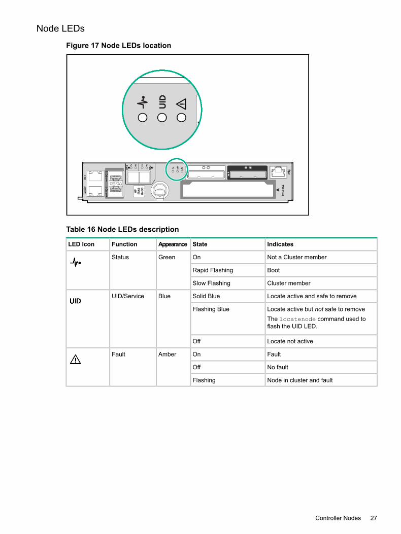
Node LEDs
Figure 17 Node LEDs location
Table 16 Node LEDs description
IndicatesStateAppearanceFunctionLED Icon
Not a Cluster memberOnGreenStatus
BootRapid Flashing
Cluster memberSlow Flashing
Locate active and safe to removeSolid BlueBlueUID/Service
Locate active but not safe to removeFlashing BlueThe locatenode command used toflash the UID LED.
Locate not activeOff
FaultOnAmberFault
No faultOff
Node in cluster and faultFlashing
Controller Nodes 27

Installing EnclosuresThe system can include the following types of enclosures:• 3PAR StoreServ 8000 Storage SFF 2.5-inch Controller Node Enclosure:
Holds up to 24 SFF 2.5-inch drives in a single horizontal row at the front of the driveenclosure.
◦
◦ Contains two 580 W (gold series) PCMs in the rear of the enclosure.
◦ Contains two I/O modules in the rear of the enclosure.
Figure 18 (page 28) shows the 2.5-inch drive enclosure and also applies to the 3PARStoreServ 8000 Storage controller node enclosure and the stand-alone SFF drive enclosures.
• 3PAR StoreServ 8000 Storage LFF 3.5-inch Drive Enclosure:
Holds up to 24 LFF 3.5-inch drives in four vertical columns at the front of the driveenclosure.
◦
◦ Contains two 580 W (gold series) PCMs in the rear of the enclosure.
◦ Contains two I/O modules in the rear of the enclosure.
Figure 19 (page 28) shows the 3.5-inch drive enclosure and only applies to the LFF driveenclosure.
Drive Enclosure NumberingThere are two types of drive enclosures. The maximum number of supported drive enclosuresvaries based on the model and the number of controller nodes. Drives are mounted on a drivecarrier or magazine and are located at the front of the enclosures.
• 2.5-inch drive numbering
Figure 18 SFF 2.5-inch drive enclosure—drive numbering
• 3.5-inch drive numbering
Figure 19 LFF 3.5-inch drive enclosure—drive numbering
28 Identifying System Components and Numbering

In the HPE 3PAR StoreServ Management Console (SSMC) or HPE 3PAR CLI, the enclosuresare displayed as follows:• DCS8 = SFF 2.5-inch drive enclosure
• DCS7 = LFF 3.5-inch drive enclosure
• DCN2 = controller node enclosure
DrivesDrive types:• FC SFF 10 K or 15 K
• NL SFF and LFF 7.2 K
• SSD SFF 480 GB, 920 GB, 1.92 TB, 3.84 TB
• SSD LFF 480 GBDrive sizes:• SFF 2.5-inch drives—Can be installed only in SFF 2.5-inch drive enclosure and the controller
node enclosures.• LFF 3.5-inch drives—Can be installed only in the LFF 3.5-inch drive enclosure.For more information, see “Drives Installation” (page 65).
Drives 29

Drive LEDs
Figure 20 Drive LEDs location
Table 17 Drive LEDs
IndicatesStatusAppearanceLED Function
Drive failed and ready for replacementOnAmberFault1
The locatecage command is issued,which flashes all drive fault LEDs for up
Flashing
to 15 minutes. (The I/O module FaultLEDs at the rear of the enclosure alsoflash). Fault LEDs for failed drives do notflash.
Normal operationOnGreenStatus2
ActivityFlashing
30 Identifying System Components and Numbering

I/O ModuleThe I/O modules connect the controller nodes to the drives using mini-SAS cables, enabling thetransfer of data between the controller nodes, drives, PCMs, and enclosures.
• The I/O modules are located at the rear of the drive enclosures and are numbered 0 to 1from bottom to top.
• The I/O Module base 0 is identified by its red label and the base 1 is identified by its greenlabel.
See Figure 22 (page 32) and Figure 23 (page 32)).
I/O Module LEDs
Figure 21 I/O Module LEDs location
Table 18 I/O Module LEDs description
IndicatesStateAppearanceFunctionLED Icon
PowerOnGreenPower
No powerOff
Locate active and safe to removeOnBlueUID/Service
Locate active but not safe to removeFlashing
Locate not activeOff
FaultOnAmberFault
No faultOff
I/O Module 31

I/O Module Numbering
Figure 22 I/O modules—numbering SFF 2.5-inch drive enclosure
Figure 23 I/O modules—numbering LFF 3.5-inch drive enclosure
32 Identifying System Components and Numbering

SAS Ports LEDs
Figure 24 I/O module—SAS ports LEDs location
Table 19 I/O module—SAS ports LEDs description
IndicatesStateAppearanceFunctionLED Icon
Links up, but no activityOnGreenActivity
No cable, bad cable, not ready or nopower
Off
ActivityFlashing
FaultOnAmberFault
No faultOff
I/O Module 33

Power Cooling ModulesThe power cooling module (PCM) is an integrated power supply and cooling fan.There are two types of PCMs:• 580 W (gold series) PCM—Used in the drive enclosures.
• 764W (gold series) PCM—Used in the controller node enclosures and includes a replaceablebattery.
The PCMs are located at the rear of the system and on the sides of the enclosure. There aretwo PCMs per enclosure. The PCMs are numbered 0 and 1 from left to right. In the LFF 3.5-inchdrive enclosure, the two PCMs are located diagonally from one another and the remaining PCMslots are filled with blank panels (see Figure 30 (page 38)).
CAUTION: Do not proceed without first correcting all fault indications (except for PCM batteries).
NOTE: The batteries are fully charged during shipment. The batteries might lose some chargeand show a degraded status immediately when power is applied. This is a temporary condition.Proceed with the system initialization process and software installation. Check the LEDs againwhen the installation is complete.
The cluster is not formed until the HPE 3PAR OS software configuration has been performed.
34 Identifying System Components and Numbering

764 W PCM LEDs—Node Enclosure
Figure 25 764 W PCM LEDs location—node enclosure
Table 20 764 W PCM LEDs description—node enclosure
IndicatesStateAppearanceFunctionLED Icon
No AC power or PCM faultOnAmberAC input fail
Firmware downloadFlashing
AC present and PCM On / OKOnGreenPCM OK
Standby modeFlashing
PCM fail or PCM faultOnAmberFan Fail
Firmware downloadFlashing
No AC power or fault or out of toleranceOnAmberDC Output Fail
Firmware downloadFlashing
Hard fault (not recoverable)OnAmberBattery Fail
Soft fault (recoverable)Flashing
Present and chargedOnGreenBattery Good
Charging or disarmedFlashing
Power Cooling Modules 35

764 W PCM Numbering—Node Enclosure
Figure 26 PCMs—numbering 2-node (2U) node enclosure
Figure 27 PCMs—numbering 4-node (4U) node enclosure
36 Identifying System Components and Numbering

580 W PCM LEDs—Drive Enclosure
Figure 28 580 W PCM LEDs location—drive enclosure
Table 21 580 W PCM LEDs description—drive enclosure
IndicatesStateAppearanceFunctionLED Icon
No AC power or PCM faultOnAmberAC input fail Partner PCM Faulty/Off or Firmware
DownloadFlashing
AC Present and PCM On / OKOnGreenPCM OK
Standby modeFlashing
PCM fail or PCM faultOnAmberFan Fail
Firmware downloadFlashing
No AC power or fault or out of toleranceOnAmberDC Output Fail
Firmware downloadFlashing
Power Cooling Modules 37

580 W PCM LEDs—Drive Enclosure
Figure 29 PCMs—numbering SFF 2.5-inch drive enclosure
Figure 30 PCMs—numbering LFF 3.5-inch drive enclosure
38 Identifying System Components and Numbering

Power Distribution UnitsIn each HPE Intelligent Series Rack, four PDUs are mounted at the bottom of the rack.PDU numbering:• PDUs mounted horizontally—Numbered 0 to 1 from bottom to top.
• PDUs mounted vertically—Numbered 0 to 1 from left to right.Verify that there is enough clearance for service.For example:• The PDUs mounted vertically at the rear of a rack must have enough clearance to remove
controller node and drive chassis power supples.• The PDUs mounted vertically at the bottom of the rack so to provide a front-mounting unit
space.
Service ProcessorThere are two types of service processors:
• Physical service processor (SP)
SPS (single power supply)◦◦ RPS (redundant power supply)
• Virtual service processor (VSP)If your configuration includes a physical SP, it is located at the bottom of the rack under theenclosures and above the PDUs.
Figure 31 HPE 3PAR service processor
For more information, see “Connecting to a Physical Service Processor” (page 96).
Power Distribution Units 39

Service Processor LEDsThe HPE 3PAR SP LEDs are located at the front and rear of the SP.
Figure 32 SP LEDs location—front panel
Table 22 SP LEDs description—front panel
IndicatesStateAppearanceLED Function
System onOnGreenPower On/1Standby button andsystem power Performing power on sequenceFlashing
System in standby, power still onOnAmber
Power cord not attached or power failureOff
System on and system health normalOnGreenHealth2
System health degradedFlashingAmber
System health criticalFlashingRed
System power offOff
Link to networkOnGreenNIC Status3
Network activityFlashing
No network link/activityOff
ActiveOnBlueUID/Service4
System managed remotelyFlashing
DeactivatedOff
40 Identifying System Components and Numbering

Figure 33 SP LEDs location—rear panel
Table 23 SP LEDs description—rear panel
IndicatesStateAppearanceLED/Port Function
ActivatedOnBlueUID/Service1
System managed remotelyFlashing
DeactivatedOff
Network linkOnGreenNIC Link2
No network linkOff
Link to networkOnGreenNIC Activity3
Network activityFlashing
No network activityOff
NormalOnGreenPower Supply4
NOTE: Might not beapplicable to yoursystem (for hot-plugHPE CS power suppliesONLY)
Off represents one or more of the followingconditions:
Off
• Power unavailable
• Power supply failure
• Power supply in standby mode
• Power supply error
Designated port for servicingiLO Port/Virtual Serial Port5
For more information about LED status, seeUnderstanding LED Indicator Status in theHPE 3PARStoreServ 8000 Storage Service Guide at http://www.hpe.com/info/storage/docsTo initialize the SP, see “Service Processor Initialization” (page 90).
Service Processor 41

4 Power Distribution Unit InstallationThis chapter provides installation instructions for qualified personnel for installing an HPE BasicPDU.Before installation, read the Important Safety Information that ships with the product, or see theHewlett Packard Enterprise Safety and Compliance website:http://www.hpe.com/support/importantsafetyinformation
WARNING! A risk of injury (resulting from electric shock and high energy levels) exists. Theinstallation of options and routine maintenance and service of this product must be performedby individuals who are knowledgeable about the procedures, precautions, and hazards associatedwith AC power products.
This PDU is intended only for ITE loads with linear and Power Factor Correction input current.If non-linear loads are connected, the nameplate current rating of the PDU must be reduced bya factor of 0.8.
Safety and Regulatory ComplianceFor safety, environmental, and regulatory information, see Safety and Compliance Informationfor Server, Storage, Power, Networking, and Rack Products available at the Hewlett PackardEnterprise website:http://www.hpe.com/support/Safety-Compliance-EnterpriseProducts
Important Power Safety PrecautionsFollow these safety precautions when connecting multiple hardware components to powersources:
WARNING! To reduce the risk of personal injury from high-leakage current, verify earthconnection before connecting the power supply.The summation of input power for multiple pieces of information technology equipment throughthe use of power products can result in high-leakage currents.If the total system leakage current for a system of components exceeds 3.5 mA:• The use of a detachable input power cord is prohibited.
• The input power cord must be securely attached, and it should be connected to the AC mainsby hardwiring or through the use of a non-residential, industrial-styled plug that maintainspositive earth connection.
• If the total system leakage current through the ground conductor exceeds 5% of the inputcurrent per line under normal operating conditions, the system loads should be dividedamong multiple power connections.
42 Power Distribution Unit Installation

WARNING!To reduce the risk of fire, electric shock and damage to power sources.• Connect only to a circuit providing branch circuit overcurrent protection of appropriate current
rating.• Connect the input power cord into a grounded (earthed) electrical outlet that is located near
the equipment and is easily accessible.• Be sure all circuit breakers are in the off position before connecting input power.
• Be sure that the load products connected to the HPE PDU are adjusted for, or otherwisecapable of operation from the same line voltage supplying the PDU. Failure to verify thevoltage can lead to severe equipment damage.
• Do not overload the PDU. The total input current rating of all equipment connected to eachoutput cannot exceed the total output rating marked on the PDU.
• Use only the hardware provided to install the PDU.
Required ToolsThe following tools are required for PDU installation:• Phillips screwdriver
• Torx screwdriver
NOTE: If your facility or configuration requires an L5–20R plug, you must obtain a third-partyL5–20R to NEMA 5–20P adapter before installing or connecting the HPE 1.9kVA 120V BasicPDU ( H5M54A).
Required Tools 43

Recommended PDU ConfigurationsA PDU is installed in a rack in the following configurations:• Single PDU configuration with the outlets facing the center of the rack
Figure 34 Single PDU configuration, outlets facing center
• Single PDU configuration with the outlets facing the rear of the rack
Figure 35 Single PDU configuration, outlets facing rear
44 Power Distribution Unit Installation

• Double PDU configuration with the outlets facing the center of the rack
Figure 36 Double PDU, outlets facing center
• Inverted PDU with the input power cable exiting the top of the rack
Figure 37 Inverted PDU, power cable exiting top
Recommended PDU Configurations 45
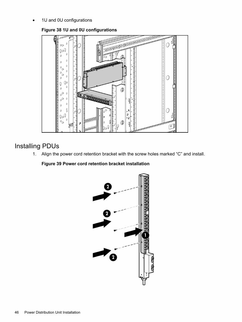
• 1U and 0U configurations
Figure 38 1U and 0U configurations
Installing PDUs1. Align the power cord retention bracket with the screw holes marked “C” and install.
Figure 39 Power cord retention bracket installation
46 Power Distribution Unit Installation

2. Align the mounting pins with the screw holes marked “M” and install.
Figure 40 Align mounting pins
3. If installing the PDU inverted, install a mounting pin on the bottom of the PDU.
Figure 41 Inverted PDU mounting pin
Installing PDUs 47
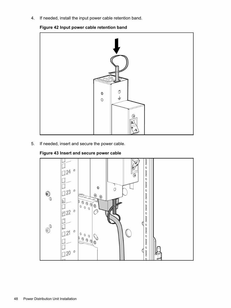
4. If needed, install the input power cable retention band.
Figure 42 Input power cable retention band
5. If needed, insert and secure the power cable.
Figure 43 Insert and secure power cable
48 Power Distribution Unit Installation

6. Install the PDU and ensure that the mounting pins are engaged with the rack.
Figure 44 Engage mounting pins
CAUTION: When moving a rack with installed components, always use the shippingbracket to secure the PDU.
7. If the PDU is not inverted, install the shipping bracket above the PDU.
Figure 45 Shipping bracket installation—PDU not inverted
Installing PDUs 49

8. If the PDU is inverted, install the shipping bracket over the mounting pin below the PDU.
Figure 46 Shipping bracket installation—PDU inverted
Installing 1U and 0U PDUs1. Attach the power cord retention bracket.
Figure 47 Attach power cord retention bracket
50 Power Distribution Unit Installation

2. Attach the appropriate mounting brackets:
Figure 48 Attach 1U mounting brackets
Figure 49 Attach 0U mounting brackets
Installing 1U and 0U PDUs 51

3. Install the cage nuts.
Figure 50 Cage nut installation
52 Power Distribution Unit Installation

4. Install the PDU:
Figure 51 1U PDU installation
Figure 52 0U PDU installation
Installing 1U and 0U PDUs 53

Securing Cable Retention BracketSecure the cable weight to the retention bracket.
Figure 53 Cable retention bracket
The installation has been completed.
54 Power Distribution Unit Installation

5 Hewlett Packard Enterprise Factory-Integrated SystemSetup
This chapter describes the procedures for setting up a system that is delivered in afactory-integrated Hewlett Packard Enterprise cabinet with all of the components installed.Before you set up a system, complete all of the configuration specifications and installationrequirements in the HPE 3PAR StoreServ 8000 Storage Site Planning Manual athttp://www.hpe.com/info/storage/docs
WARNING! Do not use this procedure if you are installing system components into an existingor partially populated rack. To install system components into an existing rack, see “SystemComponent Installation in Existing Rack” (page 59).
NOTE: Some factory-integrated systems might have controller nodes mounted in the centerof the rack.
Unpacking the CabinetThe 3PAR StoreServ 8000 Storage system comes with system components fully assembled ina Hewlett Packard Enterprise rack. Multiple racks require separate installation and cabling. Forinstallation instructions of non-factory assembled components, continue on to “System ComponentInstallation in Existing Rack” (page 59).If your system is fully assembled in a Hewlett Packard Enterprise rack:1. Inspect the packaging for damages. Report any noticeable damages to the customer, Hewlett
Packard Enterprise and carrier company.2. Refer to the diagrams on the outside of the cardboard shipping container and follow the
instructions about how to remove the packaging.
CAUTION: Use extreme caution and avoid tipping the rack. Use more than two peopleto safely guide the oversized rack down the ramp.
Positioning the Cabinet
CAUTION: To prevent potential damage to system equipment, do not adjust the position ofthe cabinet when the power is on.
Position the cabinet in the operating location. If the operating location has raised floor tiles withcutouts to facilitate cable routing, position the cabinet over the cutouts in the tiles. See theHPE 3PAR StoreServ 8000 Storage Site Planning Manual for more information on the structuralconsiderations for using raised flooring.For more information on final positioning, see “Repositioning the System” (page 83).
Stabilizing CabinetAfter positioning the system, use the four leveling feet to stabilize the cabinet and preventmovement during operation:1. Using an adjustable wrench, turn each leveling foot clockwise until the weight of the rack
rests on the leveling feet instead of the casters.2. Using the wrench, lock the leveling feet in place by turning the locking nut on each foot
counterclockwise until tight.3. Verify that the rack is stationary.
Unpacking the Cabinet 55

Cabling VerificationThe cabling for a factory-integrated system is complete. You must plug in the power cords andinstall the host and Ethernet cables.
NOTE: In a 4-node 8400/8440/8450 system, two cable management brackets have Velcrostraps to hold the cables. You can remove and discard these brackets, but Hewlett PackardEnterprise recommends saving them for future use. To remove the cable management brackets,loosen the Torx screws and unlatch the Velcro straps to free the cabling.
Cable Restraint Shipping Brackets installation and removalThe cable restraint shipping brackets support the connected data cables and connectors duringtransport. Hewlett Packard Enterprise recommends installing the brackets before transportingthe system to another location to prevent damage to the connectors. The brackets are not requiredif the system is in a stationary position, so remove and store the brackets for later use.
Installing Cable Restraint Shipping Brackets1. Connect the data cables to the enclosure.2. Attach the hook and loop straps to the brackets.3. Align the brackets so that they are parallel to the edges of the enclosure link connectors
(see Figure 54 (page 56)). Adjust the brackets to the height of the screw holes located onthe side rails.
Figure 54 Aligning cable restraint shipping brackets
56 Hewlett Packard Enterprise Factory-Integrated System Setup

4. Attach the brackets to the side rails.
Figure 55 Attaching cable restraint shipping brackets to the side rails
Cable Restraint Shipping Brackets installation and removal 57
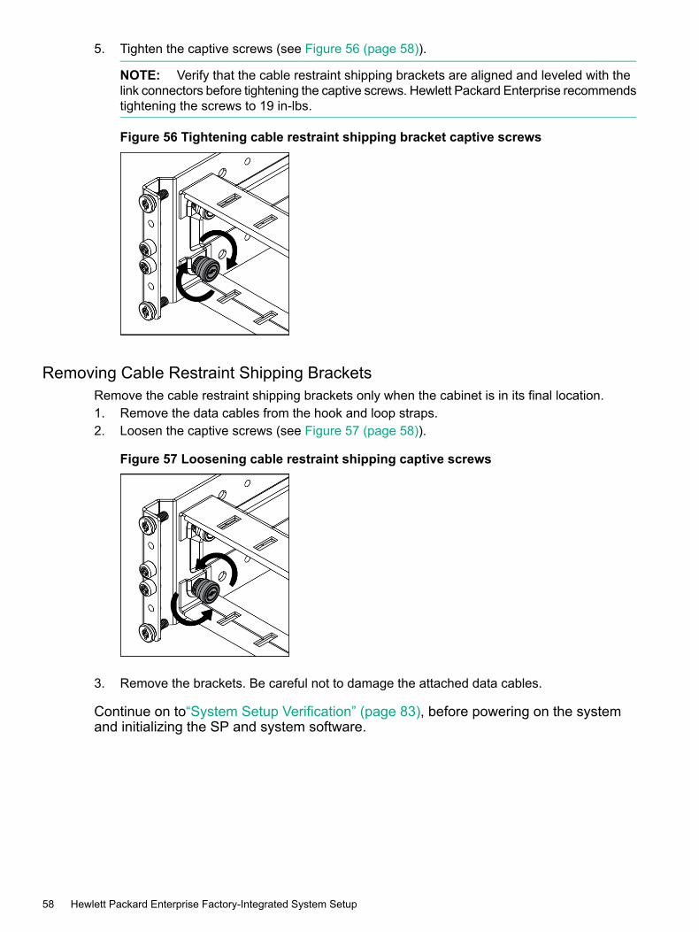
5. Tighten the captive screws (see Figure 56 (page 58)).
NOTE: Verify that the cable restraint shipping brackets are aligned and leveled with thelink connectors before tightening the captive screws. Hewlett Packard Enterprise recommendstightening the screws to 19 in-lbs.
Figure 56 Tightening cable restraint shipping bracket captive screws
Removing Cable Restraint Shipping BracketsRemove the cable restraint shipping brackets only when the cabinet is in its final location.1. Remove the data cables from the hook and loop straps.2. Loosen the captive screws (see Figure 57 (page 58)).
Figure 57 Loosening cable restraint shipping captive screws
3. Remove the brackets. Be careful not to damage the attached data cables.
Continue on to“System Setup Verification” (page 83), before powering on the systemand initializing the SP and system software.
58 Hewlett Packard Enterprise Factory-Integrated System Setup

6 System Component Installation in Existing RackThis chapter describes the procedures for installing system components in an existing rack.Before you set up a system, ensure that all requirements documented in theHPE 3PAR StoreServ8000 Storage Site Planning Manual have been met.To set up a system delivered in a fully loaded Hewlett Packard Enterprise cabinet, see “HewlettPackard Enterprise Factory-Integrated System Setup” (page 55).
Unpacking Enclosures
CAUTION: Enclosures are heavy. Two people are required for lifting, moving, or installing anenclosure.
To unpack an enclosure:1. Cut open the cardboard box and remove the top.2. Remove the rail kit.3. Remove the packing foam around the enclosure.4. Remove the enclosure from the box.
Rail Kit InstallationBefore you install an enclosure in the rack, first mount the two rail shelves to the rack.
NOTE: To mount a one unit (1U) rail shelf (used for installing an SP) to the rack, follow theinstallation instructions included with that SP 1U mounting kit.
Table 24 (page 59) lists the rail kit part numbers for each type of installation.
Table 24 Rail kit part numbers
Rail Kit Assembly 4U EnclosureRail Kit Assembly 2U Enclosure
PN 793951-001PN 793950-001
NOTE: For more information about the rail kit assembly, see “Rail Kits” (page 119).
The rail kit contains two rails, two middle support brackets, and T25 Torx screws. The rail channelsare mounted to the inside of the rack using two shoulder screws at each end of the rack (fourscrews per rail), and a middle support bracket for mounting between the adjustable rails. Installingthe middle support bracket applies only to the 2U and 4U enclosures. The front labels readFRONT RIGHT and FRONT LEFT with an arrow pointing in the front direction.
Unpacking Enclosures 59

NOTE: The middle support bracket is only used in a Hewlett Packard Enterprise rack withposts that extend to a depth of 29 inches. Install the middle support bracket when transportingthe system to another location. Retain and store the middle support brackets if they are not beingused. Installing the middle support bracket can be difficult due to limited clearance in the verticalrails of the rack.Install the middle support bracket before transporting:1. Align the middle support bracket holes with the top holes of the rails. The orientation of the
middle support bracket is neutral.2. Insert and tighten screws.
Figure 58 Middle support bracket installation
NOTE: Two kinds of T25 Torx screws are provided. The shoulder screws that fasten the railchannels to the inside of the rack are longer and have flat (not rounded) screwheads (see“Installing a 2U Rail Shelf” (page 61) or “Installing a 4U Rail Shelf” (page 61)).The shorter screws with rounded screwheads are for the middle support bracket.
60 System Component Installation in Existing Rack

Installing a 2U Rail Shelf1. Determine the location of the directional-specific rail matches with the side of a rack post.
Labels denote the FRONT RIGHT and FRONT LEFT of the rails.2. Align one end of the rail channel with the holes of the rack post, and then push to seat the
locating pins in the rack.3. Expand the rail to connect to the other end of rack post.4. Secure the front and rear of the rail assembly to the rack post using four T25 Torx shoulder
screws (two front and two rear) in the top and bottom holes. Tighten the shoulder screwswith a torque of 19 in-lbs.
Figure 59 2U rail shelf installation
5. Repeat step 1 through step 4 for the other rail.6. Check both sides at the front and rear of the rack to ensure that all screws are installed
properly.
Installing a 4U Rail Shelf1. Verify that each directional-specific rail matches with the side of a rack post.
Labels denote the FRONT RIGHT and FRONT LEFT of the rails.2. Align one end of the rail channel with the holes of the rack post, and then push to seat the
locating pins in the rack.3. Expand the rail to connect to the other end of rack post.4. Secure the front and rear of the rail assembly to the rack post using four T25 Torx shoulder
screws (two front and two rear) in the top and bottom holes. Tighten the shoulder screwswith a torque of 19 in-lbs.
5. Repeat step 1 through step 4 for the other rail.6. Snap one cage nut into the rack hole at two positions above the rail on both sides.
Rail Kit Installation 61
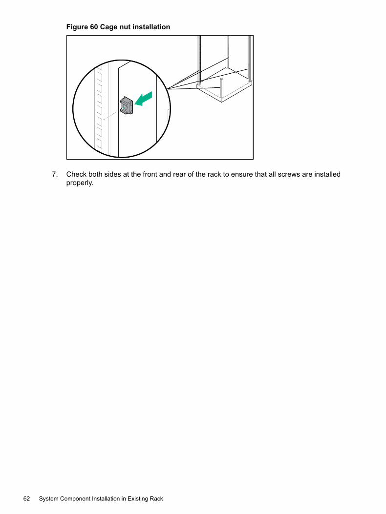
Figure 60 Cage nut installation
7. Check both sides at the front and rear of the rack to ensure that all screws are installedproperly.
62 System Component Installation in Existing Rack

Enclosures InstallationThe system can contain the following types of drive enclosures and controller node enclosures:• 2U enclosures
• 4U enclosures
CAUTION: Enclosures are heavy. Lifting, moving, or installing an enclosure requires twopeople. Always use at least two people to lift an enclosure into the rack. If the enclosure is beingloaded into the rack above chest level, a third person must assist with aligning the enclosure withthe rails, while the other two people support the weight of the enclosure.
NOTE: When installing a 2-node 8400/8440/8450 controller node enclosure, two units of spacemust be reserved above the enclosure to allow for a future upgrade to a 4-node system. Thereare two 1U filler panels available to reserve this space.
Installing EnclosuresTo install an enclosure in the rack:1. Determine that the enclosure is oriented correctly by looking at the rear of the enclosure.
Verify the controller node numbering by reviewing the controller node label located on bothedges of the enclosure slot.
Figure 61 Verify controller node numbering
2. At the front of the enclosure, remove the yellow panels on each side of the enclosure toprovide access to the mounting holes.
3. Using both hands, position the right rail at the desired rack unit position in the rack, and thenslide the enclosure onto the rail shelves.
CAUTION: Always use at least two people to lift an enclosure into the rack. If the enclosureis being loaded into the rack above chest level, a third person must assist with aligning theenclosure with the rails, while the other two people support the weight of the enclosure.
Enclosures Installation 63

4. At the front of the enclosure, do one of the following steps:• 2U enclosures—Insert one Torx M5 (long) screw into the mounting hole on each side
to secure the enclosure to the rack. Tighten the screws to a torque level of 13 in-lbs.• 4U enclosures—Insert two Torx M5 (long) screws into the mounting holes on each
side to secure the enclosure to the rack (on each side, one screw goes into the rail andthe other to the cage nut). Tighten the screws to a torque level of 13 in-lbs.
5. At the rear of the enclosure, tighten the two T25 slot (short) hold-down screws on the sidesof the enclosure. Tighten the screws to a torque level of 13 in-lbs. See Figure 62 (page 64).
Figure 62 Tighten the enclosure hold-down screws
NOTE: Due to limited access, use a short length or right angle Torx bit screwdriver totighten the hold-down screws.
6. Reinsert the yellow panels on each side of the enclosure.7. Connect the power cables to the power supplies, connect the data cables, and then secure
them with cable straps.
WARNING! Do not power on without completing the remainder of the physical installation.
8. Remove the appropriate number of drive blanks from the front of the drive enclosure9. Add the storage drives to the front of the drive enclosure bays, starting from bay 0 and
continuing sequentially.10. To ensure proper thermal control, install blank filler panels into any empty slots.
64 System Component Installation in Existing Rack

Drives InstallationBefore installing drives, see “SFF 2.5-inch drive—Allocating and Loading Guidelines” (page 65)and “LFF 3.5-inch drive—Allocating and Loading Guidelines” (page 68).
CAUTION:• Blank drive-filler panels are provided and must be used in any empty drive slots in the
enclosure to ensure proper thermal control. Operate the enclosure only when all bays arepopulated with either a component or a blank.
• To avoid potential damage to equipment and loss of data, handle drives carefully followingindustry-standard practices. Internal storage media can be damaged when drives are shaken,dropped, or roughly placed on a work surface.
• If the system is enabled with the Data-at-Rest (DAR) encryption feature, only use theself-encrypting drives (SED) or Federal Information Processing Standard (FIPS) capabledrives. Using a non-self-encrypting drive might cause errors during the upgrade process.For information about encrypting the drives with an enhanced security feature known asData-At-Rest (DAR) encryption, see “Enhancing Security with Data Encryption” (page 121).
NOTE:• The drives added to the drive enclosure on each controller node pair should be balanced
across controller node pairs, then across device ports on each controller node pair, andfinally by enclosures on the same port.
• To avoid any cabling errors, all enclosures must have drive pairs installed before poweringon the enclosure.
• Each drive includes a green and amber LED on the front to indicate drive status. See “DriveLEDs” (page 30).
• For the 8450 AFA model, only SSDs (solid state drives) are supported.
• In a system with a mix of 3PAR StoreServ 8000 Storage 2.5-inch drive enclosure and 3PARStoreServ 8000 Storage 3.5-inch drive enclosure, there is a minimum of six drives for eachdrive enclosure. Additional upgrades can include all 2.5-inch, 3.5-inch, or a mixture of 2.5-inchand 3.5-inch drives, but they must be in pairs of the same drive type.
Drive types:• FC SFF 10 K or 15 K
• NL SFF and LFF 7.2 K
• SSD SFF 480 GB, 920 GB, 1.92 TB, 3.84 TB
• SSD LFF 480 GBFor information about adding drive enclosures, see “Adding Drives and Expansion DriveEnclosures” (page 122).
SFF 2.5-inch drive—Allocating and Loading Guidelines
Figure 63 SFF 2.5-inch drive enclosure—drive loading order
Drives Installation 65

Best Practices—SFF Drive Allocating and Loading GuidelinesWhen allocating and loading drives in enclosures, the following are the Hewlett PackardEnterprise recommended best practice guidelines:• Load SFF drive types (FC, NL, and SSD) in pairs.
• Load starting from slot 0 on the left and filling the slots sequentially to the right.
• Load all of the same drive types in adjacent slots before loading the next drive type.
• Allocate the same number of drive-type pairs to every enclosure in the system.
Example 1Figure 64 (page 66) shows an SFF enclosure loaded with two pairs of FC drives, three pairs ofNL drives, and two pairs of SSDs.
Figure 64 SFF drive allocation (one enclosure)
Example 2Figure 65 (page 66) shows two SFF enclosures loaded with three pairs of FC drives, five pairsof NL drives, and two pairs of SSDs.
Figure 65 SFF drive allocation (two enclosures)
Avoid Practices—SFF Drive Allocating and Loading GuidelinesWhen allocating and loading drives in enclosures, the following are the Hewlett PackardEnterprise recommended avoid practice guidelines:• Avoid leaving any empty slots between drives.
• Avoid an unbalanced number of same type drives.
• Avoid loading same-type drives in slots that are not adjacent to each other.• Avoid filling an entire drive enclosure when additional enclosures are available. Leaving
empty slots in each enclosure allows for future upgrade flexibility to add a new drive typeand license features.
66 System Component Installation in Existing Rack

Avoid Practices—ExampleAvoid loading the SFF drive in the following manner, because this example demonstrates anunbalanced load, due to the NL drives not being installed in even pairs. Avoid having an oddnumber of NL drives in both cages.
Figure 66 SFF—unbalanced load
Drives Installation 67
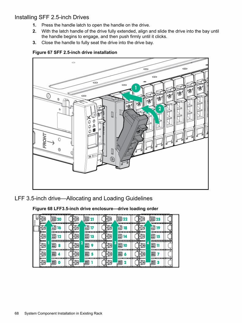
Installing SFF 2.5-inch Drives1. Press the handle latch to open the handle on the drive.2. With the latch handle of the drive fully extended, align and slide the drive into the bay until
the handle begins to engage, and then push firmly until it clicks.3. Close the handle to fully seat the drive into the drive bay.
Figure 67 SFF 2.5-inch drive installation
LFF 3.5-inch drive—Allocating and Loading Guidelines
Figure 68 LFF3.5-inch drive enclosure—drive loading order
68 System Component Installation in Existing Rack

Best Practices—LFF Drive Allocating and Loading GuidelinesWhen allocating and loading drives in enclosures, the following are the Hewlett PackardEnterprise recommended best practice guidelines:• Load LFF drive types (FC, NL, and SSD) in pairs.
• Load starting from slot 0 on the bottom of the left column and filling the slots moving upwardin the column, before moving to the bottom of the next column to the right.
• Load all of the same drive types in adjacent slots before loading the next drive type.
• Allocate the same number of drive-type pairs to every enclosure in the system.
• If there is more than one expansion enclosure in the system, load the drives in pairs so theyare balanced across the enclosure node connections DP1 and DP2, and then added toenclosures in a vertical column.
Figure 69 Best practices—LFF example
Drives Installation 69

Avoid Practices—LFF Drive Allocating and Loading GuidelinesWhen allocating and loading drives in enclosures, the following are the Hewlett PackardEnterprise recommended avoid practice guidelines:• Avoid leaving any empty slots between drives.
• Avoid an unbalanced number of same type drives.
• Avoid mixing HDD and SSD drive types in the same column.
• Avoid filling an entire drive enclosure when additional enclosures are available. Leavingempty slots in each enclosure allows for future upgrade flexibility to add a new drive typeand license features.
Avoid Practices—ExampleAvoid loading the LFF drives in the following manner, because this example demonstrates anunbalanced load, due to the NL drives being installed across all four columns. Instead, the drivesshould have been loaded in the first column before moving to the next column to the right.
Figure 70 LFF—incorrect loading order
70 System Component Installation in Existing Rack

Installing LFF 3.5-inch Drives1. Press the handle latch to open the handle.2. With the latch handle of the drive fully extended, position the drive so the handle opens from
the left, align and slide the drive into the bay until the handle begins to engage, and thenpush firmly until it clicks.
3. Close the handle to fully seat the drive into the drive bay.
Figure 71 LFF 3.5-inch drive installation
Drives Installation 71
Service Processor InstallationThe physical SP consists of the following:
• 3PAR Service Processor
• 1U Mounting Kit (PN 734806-B21)
NOTE: The SP ID is the HPE 3PAR StoreServ Storage array 10-digit serial number precededby the letters "SP". For example, if the storage array serial number is 0001614983, the SP ID isSP0001614983. The SP ID is the Hewlett Packard Enterprise 10-digit serial number. Legacy3PAR StoreServ Storage systems used 7-digit serial numbers for configuration. The 3PARStoreServ 8000 Storage no longer has a 7-digit serial number, but uses instead a 10-characterserial number for configuration.This requires up-to-date versions of HPE 3PAR SP and VSP software and of HPE 3PARSmartStart.The 3PAR StoreServ Storage system serial number can be obtained from the following:• Located at the rear of the system next to the power switch for the controller node enclosure
PCM.• Located in the product documentation provided with your system.
The following components are included in the SP 1U mounting kit:• Slide mounting rail
• Screws
• Cage nuts (for the round-hole rack)
• Cable management straps
• LabelsIn addition to the supplied items, you might also need the following:• Screws fitting a threaded-hole rack
• Screwdriver
• Optional cable management arm (see Figure 72 (page 73))
72 System Component Installation in Existing Rack

The SP 1U mounting kit supports a variety of products in round, square, or threaded-hole racks.The following table identifies any tools required for each type of rack.
Table 25 Rack types
PictureTools RequiredRack Type
NoneRound hole
NoneSquare hole
ScrewdriverThreaded hole
Figure 72 Cable management arm
Service Processor Installation 73

Installing SP Rail Kit and Service Processor
WARNING! To avoid risk of injury or damage to the equipment, do not stack anything on topof rail-mounted equipment or use it as a work surface when it is extended from the rack.
CAUTION: Always plan the rack layout before installing the equipment.For the best practices for controller node and drive enclosure positioning in specific configurations,see the HPE 3PAR StoreServ 8000 Storage Cabling Configuration Guide athttp://www.hpe.com/info/storage/docs
Use these procedures when installing the SP into an existing rack. Before you begin, verify thatyou have the proper SP 1U Mounting Kit (PN 734806-B21).1. Adjust the length of the mounting rails.2. Install the threaded-hole cage nuts and rail mounting pins into the rack hole positions where
you want to install the component. Use two cage nuts and two rail mounting pins on the frontof each rail, and two cage nuts and two rail mounting pins on the rear of each rail.
Figure 73 Install cage nuts and rail mounting pins
74 System Component Installation in Existing Rack

3. Align the mounting rail with the cage nuts, and then fasten the mounting rails to the rackwith the proper screws.
Figure 74 Mount and fasten mounting rails
4. Repeat step 1 through step 3 for the other mounting rail.
WARNING! To prevent the risk of injury or equipment damage, inspect the rack to ensurethat it is adequately stabilized before installing the SP.
Service Processor Installation 75

5. Install the side rails on each side of the SP by aligning each side rail to the component, andthen snapping it into place.
Figure 75 Installing SP
NOTE: Align the rail pin guides with the slots on the mounting rails before setting the SP.
Figure 76 Installing side rails
6. Slide the SP onto the mounting rails and into the rack.
76 System Component Installation in Existing Rack

Figure 77 Sliding SP into rack
Figure 78 Sliding SP into rack
7. Fasten the SP to the rack.
Service Processor Installation 77

8. (Optional) Install the cable management arm. See the instructions provided in the kit.9. Use the straps provided in the kit to secure all fiber and Ethernet cables. Securing the cables
prevents any improper disconnection or damages during operation.10. Connect the power cord to the facility power source. Do not power on the SP at this time.
WARNING!To reduce the risk of electric shock or damage to the equipment:• Do not disable the power cord grounding plug. The grounding plug is an important safety
feature.• Plug the power cord into a grounded (earthed) electrical outlet where it is accessible at
all times.• Unplug the power cord from the power supply to disconnect power to the equipment.
• Do not route the power cord through a walkway area or adjacent to other hardwarecomponents that might pinch or damage the cord. Pay close attention to the plug,electrical outlet, and the point where the cord extends from the component.
Continue on to “System Cabling” (page 79).
78 System Component Installation in Existing Rack

7 System CablingFor comprehensive cabling instructions for the 3PAR StoreServ 8000 Storage system, see theHPE 3PAR StoreServ 8000 Storage Series Cabling Configuration Guide:http://www.hpe.com/info/storage/docs
Cabling Controller Nodes—4-Node systemsInterconnect link cables are used with 4-node systems to interconnect the nodes.
NOTE:• 2-node system—Interconnect link ports are not used and the port LEDs should always be
off.• 4-node systems—Interconnect link ports are used to connect nodes together.
Controller nodes are numbered 0 to 3 from bottom to top. Connections between controller nodes0 and 1 and controller nodes 2 and 3 use four large interconnect link cables.These cables are directional and must be installed correctly for the system to function properly.When inserting the cables, you should hear a click to confirm the cable is correctly installed. Ifyou have to force the connector, the connector is upside down and needs to be inverted. Thedirection of the cable connection is indicated by labels on either end of the cable.In Figure 79 (page 79), see label A for interconnecting controller node 0 or 1. See label C forinterconnecting controller node 2 or 3.
Figure 79 Interconnect controller nodes
Cabling Controller Nodes—4-Node systems 79

Host/Ethernet Cables
WARNING!• Each controller node supports one Ethernet connection to a switch or hub. Separate
connections from the Ethernet switch or hub to at least two controller nodes are required tosupport redundancy. With redundancy, one IP address is shared between the twoconnections, and only one network connection is active at a time. If the active networkconnection fails, the IP address is automatically moved to the surviving network connection.
• At a minimum, the system requires one Fibre Channel (or iSCSI) connection from a hostcomputer to a controller node. Hewlett Packard Enterprise recommends separate connectionsfrom each host computer to each of the controller nodes in the system, with connectionsdistributed evenly across all controller nodes.
Table 26 External controller node connections
Recommended ConfigurationMinimum ConfigurationConnection Type
See the section Supported NetworkTopologies in HPE 3PAR StoreServ 8000Storage Site Planning Manual.
Connection from the Ethernet switch or hubto two controller nodes
Ethernet
Separate connections from host computersto each controller node, through a switch,
Connection from a host computer to onecontroller node
Fibre Channel
with connections distributed evenly acrossall controller nodesExample: SAN Switch A connected to evenports and SAN Switch B connected to oddports.
NOTE: To provide redundancy and topermit online software upgrades, bothcontroller nodes in a controller node pair (forexample, controller nodes 0 and 1 orcontroller nodes 2 and 3) must maintainconnections to each host server.
Varies according to system and networkconfiguration
NoneMaintenance
Table 27 (page 80) describes the maximum supported Fibre Channel cable length based on thecable size and port speed.
Table 27 Cable limitations for FC host connectivity
Cable Length LimitSpeedCable Size
150 meters4 Gb/s50 micron
50 meters8 Gb/s50 micron
35 meters16 Gb/s50 micron
Cabling Expansion CabinetsFor more information about cabling drive enclosures (SAS), before you continue to cable thesystem, see the HPE 3PAR StoreServ 8000 Storage Cabling Configuration Guide at:http://www.hpe.com/info/storage/docs
80 System Cabling

Cabling the Service Processor1. Connect a customer-supplied Ethernet cable to the lowest port on the server and keep the
other end of the Ethernet cable disconnected.2. Connect the power cable to PDU, but do not power on at this point.
WARNING! Do not power on the SP without completing the remainder of the physicalinstallation.
The following icon is typical, but it can vary by server.
Figure 80 Connection icon
Cabling Power to the System
WARNING! Before you begin cabling the power cords, verify that your power connections areset up correctly. See “Verifying Power Connections” (page 83).
When routing PCM power cords, ensure that power redundancy is maintained by connectingeach PCM within a shelf to a different PDU. When observed from the rear, the left side cabling(ID #0) is black, and the right side cabling (ID #1) is gray.
WARNING! The PCM latch can damage any cables that are routed in such a way that whenthe PCM latch handle is closed, it will cut into any cable that becomes wedged between the latchand the rack post. Keep the cables clear from the PCM latch mechanism.
NOTE: When installing cabling, ensure clear access to all system components. All power cordsneed to be tied and kept behind the rail column in order to access the components during servicing.
To cable the power cables:1. Locate the power cord for each PCM.
NOTE: Before inserting the power cords into the PCMs, verify that the PCM power switchis set to 0 (off).
2. Route the main power cords to a power strip or PDU. Ensure that the routed cords maintainproper service clearance.
3. Insert each end of the power cord into the power strip/PDU and PCM. Fasten the PCM powercord using the restraining clip on each PCM.
NOTE: Do not power on the PCMs at this time.
Cabling the Service Processor 81

Cabling Power Distribution UnitsPDUs can be mounted horizontally below the enclosures at the bottom of the rack. Each PDUAC cord connects to the appropriate outlet based on the type of cord and power requirementsto supply power to the system.To access the vertically mounted PDUs or servicing area, the PDUs can be lowered out of therack.1. Remove the two top mounting screws.2. Pull down on the PDU to lower.
NOTE: If necessary, loosen the two bottom screws to unhinge the bracket before pullingdown the PDU.
3. Ensure that the PDUs are in a fully lowered position before accessing.
Figure 81 Disengage PDU Pivot brackets
Cabling Power StripsPower strips can be located on the side of the rack to supply power to the PCMs. Power stripsare connected to PDUs. Do not exceed the capabilities of power strips and PDUs.
Continue on to“System Setup Verification” (page 83), before powering on the systemand initializing the SP and system software.
82 System Cabling

8 System Setup VerificationTo complete the installation, you must verify the power connection and final positioning of thesystem before powering the system on.
Verifying Power Connections
CAUTION: To avoid any cabling errors, all drive enclosures must have drive pairs installedbefore powering on the enclosure.
Verify the following before powering on the system:• Redundant power
• Power cord connections
• AC cord connections
• Main power cords
NOTE: Secure the power cord with the retainer by placing the wire into the circular loop andcinching it closed. You can slide the retainer by lifting the small tab behind the circular loop.
Redundant PowerThe racks use redundant PDUs and power supplies to provide power redundancy throughoutthe system. Before powering on the system, verify that the system has a valid redundant powerconfiguration connected to independent electrical power providers. Each of the PDUs mustconnect to a power socket with power being separately supplied by an independent electricalpower source.
CAUTION: Ensure that the system does not exceed the ratings of the power sources andPDUs, and adheres to the guidelines described in HPE 3PAR StoreServ 8000 Storage SitePlanning Manual.
Power Cord ConnectionsEach system arrives with all internal power cords configured and connected. Before poweringon the system, verify the following:
• AC cords are correctly configured and properly connected to the component.
• AC cord locks and cable ties on the PDUs and PCMs are properly connected.
• For a physical SP, the SP is properly connected to the PDU.
Repositioning the SystemInstall the rear door of the system and filler panels that might not have been completed duringinstallation.If you have not positioned the system in a permanent operating location, as described in“Positioning the Cabinet” (page 55) and the HPE 3PAR StoreServ 8000 Storage Site PlanningManual, place the system in its final position before powering on.
Verifying Power Connections 83

Acclimating the SystemBefore powering on the system, the system might require up to 24 hours to acclimatize to thenew operating environment when outside-to-inside conditions vary significantly. If the system orits components have experienced environmental changes during the transit, allow enough timefor the system to acclimatize before proceeding with the power-on sequence.
CAUTION: To prevent potential damage to system hardware, do not power on the systemuntil it is fully acclimatized. If condensation is present after the 24-hour acclimatization period,wait for all condensation to fully evaporate before completing the power-on sequence.
84 System Setup Verification

9 System Powering On and LED Status VerificationBefore powering on the system, complete the “System Setup Verification” (page 83).
Powering On the System1. Set the circuit breakers on the PDUs to the ON position and verify that the LED is green.2. Set the switches on the power strips to the ON position.
NOTE: Some power strips might not have power switches.
3. Power on the SP and verify that the Power On LED is green.4. Power on the drive enclosure PCMs and verify that the PCM OK LED is green.5. Power on the controller node enclosure PCMs and verify that the PCM OK LED is green.6. After approximately 10 minutes, allowing time for the system to boot and the cache batteries
to charge, verify the status of the LEDs as described in “Verifying LED Status” (page 85).
Verifying LED Status1. At the front of the system, verify that the bezel System Power green LED is On and the
Drive Status amber LED is Off. See “Bezel LEDs” (page 14) and “Drive LEDs” (page 30).
NOTE: If either the bezel Module Fault amber LED or Drive Status amber LED are On,do not proceed until the problem is resolved.
2. At the rear of the system, verify that the following green LEDs are On:• Controller node—see “Node LEDs” (page 27)
The controller node LEDs should be flashing green once per second. The green LEDof each controller node will flash together when the storage cluster is properly formed.
• I/O modules—see “I/O Module LEDs” (page 31).
• PCM—see “580 W PCM LEDs—Drive Enclosure” (page 37) or “764 W PCMLEDs—Node Enclosure” (page 35).
Continue on to“System Installation Checklists” (page 86), before initializingthe SP and system software.
Powering On the System 85

10 System Installation ChecklistsUse these system installation checklists to complete all the requirements before installing thestorage system software.
System Software Installation ChecklistVerify the following before you begin the installation process:• All components are installed.
• The system is properly set up and powered on.
• All LEDs are properly functioning.
• All LEDs have a status of green.
• The physical SP is installed, powered on, and assigned an IP address, or the VSP is installed,connected, and the temporary IP address is determined.
86 System Installation Checklists

Table 28 Service processor installation checklist
HPE 3PAR Service Processor
3PAR StoreServ Storage serial numberThe 3PAR StoreServ Storage system serial number can be obtained from thefollowing locations:
• At the rear of the system, next to the power switch for the controller nodeenclosure PCM
• In the product documentation provided with your system
SP Host Name
NOTE: During the SP setup process, the 3PAR StoreServ Storage must bepowered on, connected to the same network subnet as the SP, and non-initializedto allow the SP to verify the 3PAR StoreServ Storage serial number. Legacy 3PARStoreServ Storage systems used 7-digit serial numbers for configuration. The3PAR StoreServ 8000 Storage no longer has a 7-digit serial number, but usesinstead a 10-character serial number for configuration.This requires up-to-date versions of HPE 3PAR SP and VSP software and of HPE3PAR SmartStart.
Static IP address (IPv4 only)
Subnet mask
Gateway IP address
CAUTION: Do not enableDNS settings while you areinitializing the system software;the system will fail. See “3PARStoreServ Storage DetectionIssues” (page 130)You may need DNS settingslater if you want to verify remotesupport connectivity. Toconfigure DNS settings manuallyafter you have completedsoftware initialization, see“Service Processor Initialization”(page 90)
DNS settings:
• Domain name
• DNS servers
Maximum supported speed and duplex setting:
• Autonegotiate (During moment of birth (MOB), use the AUTO setting unlessyour network requires a different speed configuration. Press Enter to acceptthe default network speed, or enter the specific network speed and then pressEnter.)
• Custom duplex (half or full) and Custom speed (10, 100, or 1000 MB/s)
Proxy server settings for Remote Support (if applicable):
• Protocol
• Address and port
• Authentication information (optional)
System Support Information:
• Installation site information
• Customer information
Date and time:
System Software Installation Checklist 87

Table 28 Service processor installation checklist (continued)
• Enter manually
• Use Network Time Protocol (NTP) server information
• Time Zone
New password to assign setupusr (for use with the system setup wizards)
NOTE: All passwords for the setupusr username must be between 7 and 32characters in length and can consist of alphanumeric characters and the followingspecial characters: period (.), plus (+), dash (-), equal (=), and forward slash (/).
New password to assign 3parcust to access HPE 3PAR Service Processor OnsiteCustomer Care (SPOCC)
NOTE: All passwords for the 3parcust username must be between 7 and 32characters in length and can consist of alphanumeric characters and the followingspecial characters: period (.), plus (+), dash (-), equal (=), and forward slash (/).
88 System Installation Checklists

Table 29 System software installation checklist
3PAR StoreServ Storage system
3PAR StoreServ Storage serial numberThe 3PAR StoreServ Storage system serial number can be obtained from thefollowing:
• Located at the rear of the system next to the power switch for the controllernode enclosure PCM
• Located in the product documentation provided with your system
3PAR StoreServ Storage system name
IP address (IPv4 only)
Subnet mask
Gateway IP address
Date and time:
• Copy from the SP
• Enter manually
• Use Network Time Protocol (NTP) server information
• Time Zone
New password to assign 3paradm (to access the system)
NOTE: Passwords for the 3paradm username can include all printable charactersand be between 6-8 characters in length.
HPE 3PAR SmartStart
Performing host configurations after using 3PAR SmartStart for installation setuprequires an available server to run Microsoft Windows Server 2008 R2, x64 Edition;Windows Server 2012; or Windows 7.
System Software Installation Checklist 89

11 Service Processor InitializationThe SP supports all actions required for maintenance of the system. The SP provides real-time,automated monitoring and remote access to HPE 3PAR Support in order to diagnose and resolvepotential problems. A system can include either a VSP or physical SP.Use the following table as guidance for setting up a specific type of SP.
ActionType of Service Processor
See “Connecting to a Physical Service Processor” (page 96).Physical service processor (SP)
See “Connecting to a Virtual Service Processor with VMware ESXi”(page 90).
Virtual service processor (VSP)
Connecting to a Virtual Service Processor with VMware ESXiVSP supports VMware ESXi versions 4.1 and later.
WARNING! Do not install the VSP on the same 3PAR StoreServ 8000 Storage system, becauseit might lead to the inability of properly managing the array when connectivity to the storage isunavailable.Provision the VSP on a VMware server and ensure that the VSP boots from the local disk of theassigned VMware server, not from the 3PAR StoreServ 8000 LUNs.
CAUTION: VMware vMotion is not a supported application. Do not use vMotion to migrate theVSP from one physical server to another. Using vMotion might cause communication failure andinterrupt system service.
Prerequisites for Using a Virtual Service ProcessorBefore you connect to a VSP, review and complete the following tasks:• dev comment: This item corresponds to this customer advisory, “3PAR Virtual Service
Processor for Hyper-V — Installation May Fail If the Hyper-V Server Data and Time Are NotCurrent”, at http://h20564.www2.hpe.com/hpesc/doc/public/display?docId=emr_na-c04816365Ensure that the ESXi time and date are properly set, either through the Network Time Protocol(NTP) server or manually through the ESXi console. Setting the correct date and time ensuresVSP real-time monitoring and access.
• Verify that both the VSP and the 3PAR StoreServ Storage system are on the same subnet.
• Verify that the VMware vSphere client is available before deploying the VSP OVF file. Accessyour ESXi server to download the VMware vSphere client or see the VMware website:https://my.vmware.com/web/vmware/downloads
NOTE: Open Virtualization Format (OVF) is an open standard for packaging and distributingvirtual machines or software.
• Verify that the HPE 3PAR VSP software DVD is available.
90 Service Processor Initialization

NOTE: Installation DVDs are not typically shipped with the system. If you selected theLicense to Use (LTU) delivery method of physical delivery when ordering your system, usethe installation media that was shipped at the time of your order.If you selected electronic delivery, see the HPE e-Software Delivery Confirmation email fordetailed instructions for downloading the 3PAR SmartStart installation software. Thee-Software Delivery Confirmation email was sent at the time of purchase to your ITadministrator, product manager, or purchasing agent.If you cannot locate the DVD, contact Hewlett Packard Enterprise Support through http://www.hpe.com/support/hpesc and request assistance with the 3PAR StoreServ 8000Storage product.
NOTE: Use the installation media that was shipped with your order. If you do not haveinstallation media, download the latest Hewlett Packard Enterprise software at:http://www.hpe.com/support/softwaredepotOn Microsoft Windows systems, you must have administrative privileges and be a memberof the Administrators group. On Linux systems, you must have superuser access.
Connecting to a Virtual Service Processor with VMware ESXi 91

Deploying Virtual Service Processor OVF File
NOTE: The VSP supports VMware ESXi versions 4.1 and later. For more specific VMwareenvironment support, see the VMware compatibility matrix on the VMware website. The followingset of instructions might vary depending on the version of VMware ESXi you are using.
1. Insert the HPE 3PAR VSP software DVD.2. In the VMware vSphere Client window, select File > Deploy OVF template.3. On the Source page, click Browse to locate the OVF file on the DVD.4. Select the OVF file, click Open and then click Next.5. On the OVF Template Details page, verify that the OVF template is selected, and then click
Next.6. On the Name and Location page, create a name for the VSP, and then click Next.7. On the Storage page, select a storage destination for the virtual machine files, and then
click Next.
NOTE: When deploying from the VMware VirtualCenter, specify the host to deploy theVSP from the Host/Cluster page.
8. On the Disk Format page, select Thin Provision, and then click Next.9. On the Network Mapping page, map the virtual machine to the networks in your inventory,
and then click Next.10. On the Ready to Complete page, do the following steps:
a. Review the deployment settings.b. Select the Power on after Deployment checkbox. Selecting this option powers on the
VSP after the installation is complete.c. Click Finish.A Deployment Completed Successfullymessage should appear after a few minutes.
11. Click Close.12. On the left navigation pane, verify that the system is on and the green icon is displaying on
the new VSP. If necessary, expanding navigation tree to find the deployed VSP.a. Right-click the VSP in the virtual machine list.b. Select Open Console.
The VSP is now ready to set up. Continue on to “Establishing Virtual Service Processor IPAddress” (page 92).
Establishing Virtual Service Processor IP AddressAfter verifying the connection to the VSP, you must perform one of the following options:• Option A: Determine the temporary IP Address of the VSP in a DHCP environment.
• Option B: Set the IP address of the VSP in a non-DHCP environment.
Option A: DHCP Network EnvironmentTo determine a temporary IP address for the VSP:1. In the VMware vSphere Client window, select the Summary tab and wait 5-10 minutes for
the IP address to appear (in the General section, IP address field).2. Make a note of this VSP IP address, and then launch 3PAR SmartStart.3. Continue on to “Service Processor and System Setup” (page 98) to set up the VSP with
3PAR SmartStart over the public network. If you are not using 3PAR SmartStart, see“Installing HPE 3PAR Storage Software When HPE 3PAR SmartStart is Unavailable” (page127) to manually launch the setup wizards.
92 Service Processor Initialization

Option B: Non-DHCP EnvironmentTo set the IP address of the VSP:1. In the VMware vSphere Client window, select theConsole tab, click anywhere on the screen,
and press Enter.2. Log on as setupusr. Press Enter.
A password is not required to configure the network settings.3. Enter the SP IP address and press Enter.4. Enter the Netmask address and press Enter.5. Enter the default gateway address and press Enter.6. Enter Y to configure the network and press Enter.7. Review the configuration confirmation and record the VSP IP address for reference during
subsequent setup procedures with 3PAR SmartStart or the 3PAR Service Processor SetupWizard.
8. Press Enter to exit.9. Press Ctrl-Alt to release the cursor.10. Continue on to “Service Processor and System Setup” (page 98) to set up the VSP with
3PAR SmartStart over the public network. If you are not using 3PAR SmartStart, see“Installing HPE 3PAR Storage Software When HPE 3PAR SmartStart is Unavailable” (page127).
NOTE: This network configuration is temporary. If the VSP is rebooted, you will need torepeat this procedure before continuing to the SP configuration.
Importing the HPE 3PAR VSP into Hyper-VThis section describes the prerequisites and procedures for importing the VSP into Hyper-V.
WARNING! Do not install the VSP on the same 3PAR StoreServ 8000 Storage system thatthe VSP manages, because it might lead to the inability of properly managing the array whenconnectivity to the storage is unavailable.Provision the VSP on a Hyper-V server and ensure that the VSP boots from the local disk of theassigned Hyper-V server, not from the 3PAR StoreServ 8000 Storage LUNs.
System Requirements• Host operating system requirements:
NOTE: Hyper-V is supported only on x86-64 versions of Windows Server.
◦ Microsoft Windows Server 2012 R2 (Standard or Datacenter Edition)
◦ Microsoft Windows Server 2008 R2 (Standard, Enterprise, or Datacenter Edition)
◦ Microsoft Windows Server 2012 (Standard or Datacenter Edition)
• Processor requirements:
x86-64 processor version◦◦ Hardware-assisted virtualization support
NOTE: This support is available in processors that include a virtualization option,such as Intel VT or AMD Virtualization (AMD-V).
Importing the HPE 3PAR VSP into Hyper-V 93

◦ NX bit-compatible CPU
◦ Hardware Data Execution Prevention (DEP) enabled
NOTE: The settings for hardware-assisted virtualization and hardware-enforced DEPare available in the BIOS. However, the names of the settings may differ based on themanufacturer of the computer.
• Memory requirement:
◦ Minimum 2 GB
• Hard disk space requirement :
◦ Minimum 256 GB
Prerequisites for Using a VSPdev comment: bug 146794, bug 146794. In the CSI 8000 self install guide, the prerequisiteswere moved to the prerequisites chapter; here in the ERF 8000 installation guide, the Hyper-Vprerequisites are staying here as a subsection.Before you connect to a VSP, review and complete the following tasks:• Make sure that the Hyper-V server (Windows 2012 R2, Windows Server 2012, or Windows
Server 2008 R2) time and date are properly set, either through the Network Time Protocol(NTP) server or manually through the Windows OS date and time settings. Setting the correctdate and time ensures VSP real-time monitoring and access.
• Verify that both the VSP and the 3PAR StoreServ Storage system are on the same subnet.
• Verify that the VMware vSphere client is available before deploying the VSP OVF file. Accessyour ESXi server to download the VMware vSphere client or see the VMware website:https://my.vmware.com/web/vmware/downloads
• Verify that the 3PAR VSP software DVD is available.
NOTE: Installation DVDs are not typically shipped with the system. If you selected theLicense to Use (LTU) delivery method of physical delivery when ordering your system, usethe installation media that was shipped at the time of your order.If you selected electronic delivery, see the e-Software Delivery Confirmation email for detailedinstructions for downloading the 3PAR VSP software DVD installation software. Thee-Software Delivery Confirmation email was sent at the time of purchase to your ITadministrator, product manager, or purchasing agent.If you cannot locate the 3PAR VSP software DVD, contact Hewlett Packard EnterpriseSupport through http://www.hpe.com/support/hpesc and request assistance with the3PAR StoreServ 8000 Storage product.
NOTE: If you do not have installation media, download the latest Hewlett Packard Enterprisesoftware at:http://www.hpe.com/support/softwaredepotOn Microsoft Windows systems, you must have administrative privileges and be a memberof the Administrators group. On Linux systems, you must have superuser access.
94 Service Processor Initialization

Pre-Import Task Overview1. Install Hyper-V 2008 R2 or Hyper-V 2012 on a Windows Server operating system. For more
information about how to install Hyper-V, visit the following website:http://technet.microsoft.com/en-us/library/cc732470(v=ws.10).aspx#BKMK_step1(http://technet.microsoft.com/en-us/library/cc732470(v=ws.10).aspx#BKMK_step1)
2. From the DVD, download the self-extractable .exe file.3. Make sure that two physical Ethernet adapters are available on the host machine and that
they are connected, enabled, and up.4. Make sure that two virtual network switches are available and bound to the two physical
Ethernet adapters. To do this, see “Creating Virtual Network Adapters and Binding Them tothe Physical Ethernet Adapters” (page 95).
NOTE: If you use the default settings when you configure the Hyper-V service on a server thatis running Windows Server, one virtual network adapter is created and bound to the first physicalEthernet adapter.
Creating Virtual Network Adapters and Binding Them to the Physical EthernetAdapters
1. In the Actions pane of the Hyper-V Manager application, click Virtual Network Manager.2. In the Virtual Network Manager dialog box, click New virtual network, select External,
and then click Add.3. In the Virtual Network Properties area, enter a name for the virtual network in the Name
field. Then, click to select External and enter the name of the adapter you want to connectthe network to. Make sure that the Allow management operating system to share thisnetwork adapter check box is selected.
4. Click Apply.
Importing the VSP into Hyper-V Using a Virtual Hard Drive Package1. From the DVD, download the appropriate virtual hard drive package for the service processor
version that you are running.2. Run the package as administrator.3. At the prompt, enter the name of the virtual machine that you want to set, and then press
Enter. The import process starts.
NOTE: For versions of the 3PAR Service Processor earlier than 4.3: After the VM isimported, the script lists the available network switches. At the prompt, enter two switchesfrom this list that you want to connect to the virtual-machine legacy network adapters.If the switches that you select are not present on the host Hyper-V machine, you will receivean error message, and the process will stop.
4. To verify that the VSP has been imported, locate the VSP name in the Virtual Machinesarea of the Server Manager dialog box in the Hyper-V Manager application.
Importing the HPE 3PAR VSP into Hyper-V 95

Connecting to a Physical Service ProcessorUse the following instructions to connect to a physical SP installed in the rack.
NOTE:• Do not continue with the section if you are using a VSP.
• If you have a factory-integrated Hewlett Packard Enterprise cabinet with pre-installedcomponents, including the SP, no installation is necessary. See “Service Processor andSystem Setup” (page 98).
Configuring Physical Service Processor IP AddressThe following example uses Microsoft Windows 7 to configure the SP IP address and theprocedures might vary depending on the type of OS being used.1. At the rear of the system, connect one end of the network cable to the lowest numbered
Ethernet port on the SP. The Ethernet port label might vary with the server, but port 1 istypically represented by the following:
Figure 82 Port 1 label
2. Connect the other end of the cable to the Ethernet port on the laptop.3. Configure LAN settings on the laptop:
NOTE: The configuration procedures might vary depending on the version of MicrosoftWindows, Apple Mac, or Linux OS in use.
a. Select Control Panel > Network and Internet > Network and Sharing Center, andclick Change adapter settings.
b. Right-click the connection name for the port, and select Properties.c. In the Properties dialog box, on the Networking tab, double-click Internet Protocol
Version 4 (TCP/IPv4) in the list.d. In the Internet Protocol Version 4 (TCP/IPv4) Properties dialog box, make note of
your current settings.e. Select Use the following IP address, and enter the following:
• IP address: 192.168.0.2
• Subnet mask: 255.255.255.0
• Default gateway: 192.168.0.1f. Click OK and Close to confirm and activate your changes.
4. In a browser window, enter https://192.168.0.100/sp/SetIpAddress.html.5. Log in with the user ID setupusr. Leave the password box blank.
The Service Processor IP Setup wizard is displayed.
NOTE: The 3PAR Service Processor Setup Wizard might not display correctly when usingMicrosoft Internet Explorer 10 with default security settings. If the wizard continues to displayincorrectly, try refreshing the browser page.
96 Service Processor Initialization

6. In the Assign IP Address pane, enter the SP IP address to be used on the customer LAN.While you are entering an IP address, the IP Address field indicates an error. After youhave entered a valid IP address, the Subnet Mask and Gateway fields are automaticallypopulated.You can customize settings for the Subnet Mask and Gateway if required.
7. Select Next, review the Summary screen, and then select Next when you are ready.The settings are applied.
NOTE: You might see a dialog box indicating the laptop is unable to connect to the SP.This dialog box remains displayed until the adapter settings have been changed in the SPand verified. No action is necessary; the dialog box closes within three minutes.
NOTE: If the Service Processor IP Setup wizard fails, see “The Service Processor IPSetup Wizard Fails or Hangs” (page 131) for resolution.
8. Select Finish when completed.9. Repeat Step 3 and re-configure the original LAN settings on the laptop.10. Disconnect the network cable from the laptop, and connect the SP to the customer LAN.11. Continue on to “Service Processor and System Setup” (page 98) and set up the SP with
3PAR SmartStart over the public network.If you are not using 3PAR SmartStart, see “Installing HPE 3PAR Storage Software WhenHPE 3PAR SmartStart is Unavailable” (page 127).
Connecting to a Physical Service Processor 97

12 Service Processor and System SetupBefore you begin setting up the system, complete the system installation checklists:• See Table 28 (page 87)
• See Table 29 (page 89).
HPE 3PAR SmartStart Prerequisites• Microsoft Windows 2008 R2 Server x64 Edition or 2012 is currently running in the system
• 1.0 gigahertz or higher processor
• 1 GB of installed RAM (2 GB recommended)
• CD-ROM or DVD-ROM drive
• 1280 x 1024 or better screen resolution3PAR SmartStart Online Help is supported in the following browser versions:• Microsoft Internet Explorer 8, 9, and 10
• Mozilla Firefox 14 through 21After completing the checklist, continue on to “HPE 3PAR SmartStart System Setup” (page 99).
98 Service Processor and System Setup

HPE 3PAR SmartStart System SetupTwo separate 3PAR SmartStart setup Wizards assist with the set up of the system:• 3PAR Service Processor Setup Wizard
• HPE 3PAR Storage System Setup WizardThe setup is sequential and involves the following processes:• Customizing the communication settings of the SP with the 3PAR Service Processor Setup
Wizard• Setting up the storage system with the 3PAR Storage System Setup WizardYou need to set up the SP and 3PAR StoreServ Storage system only once for each new system.Before inserting the 3PAR SmartStart CD, the following system requirements must be met.
NOTE: If you cannot locate your CD, go to the following website: http://www.hpe.com/support/softwaredepot-3PAR.
To launch 3PAR SmartStart:1. Insert the 3PAR SmartStart CD.2. Follow the onscreen instructions to launch the application. If the auto-run menu does not
appear, navigate to DVD drive, and double-click the smartstart.exe file.
NOTE: The 3PAR SmartStart application might take up to 3 minutes to launch.
Continue on to “HPE 3PAR Service Processor Setup Wizard” (page 100) and launch the 3PARService Processor Setup Wizard.If 3PAR SmartStart is unavailable, see “Manually Launching the HPE 3PAR Service ProcessorSetup Wizard” (page 127) and learn how to manually launch the 3PAR Service Processor SetupWizard.
NOTE: For additional information and help, use the 3PAR SmartStart online help (accessibleby pressing F1).
HPE 3PAR SmartStart System Setup 99

HPE 3PAR Service Processor Setup WizardThe 3PAR Service Processor Setup Wizard proceeds through the following wizard steps:• Welcome
• Generate SP ID
• Networking
• Remote Support
• System Support Information
• Time and Region
• Change Passwords
• Summary
• Applying Settings
• FinishFollow the instructions on each screen, and then click Next to proceed to the next wizard step.To launch the wizards in 3PAR SmartStart:1. Verify that the SP is powered on.2. Click the Initialize Service Processor link in 2 Initialize Service Processor.3. Enter the SP IP address and click OK.
NOTE: When configuring in a DHCP network environment, enter the VSP temporary IPaddress.
NOTE: A security certificate error might occur when there is a problem with a web server'suse of the certificate and a blocking page will appear. You can ignore the warning andcontinue to go to the website.
4. On the browser window, enter setupusr in the User Name box, and leave the passwordbox blank.
5. Click OK.
NOTE: The 3PAR Service Processor Setup Wizard might not display correctly when usingMicrosoft Internet Explorer 10 with default security settings. If the wizard continues to displayincorrectly, try refreshing the browser page.
100 Service Processor and System Setup

SP Wizard Step 1—WelcomeThe Welcome page shows the information that is required to complete the wizard and set upthe SP.The setup takes about 15 minutes.1. Obtain the following information:
• 3PAR StoreServ Storage 10-digit serial number
NOTE: Legacy 3PAR StoreServ Storage systems used 7-digit serial numbers forconfiguration. The 3PAR StoreServ 8000 Storage no longer has a 7-digit serial number,but uses instead a 10-character serial number for configuration.This requires up-to-date versions of HPE 3PAR SP and VSP software and of 3PARSmartStart.
• SP network configuration:
◦ The name to be assigned to the SP
◦ IP address (IPv4 only)
◦ Subnet mask and gateway, if you are using custom settings
◦ DNS settings
CAUTION: Do not enable DNS settings while you are initializing the systemsoftware; the system will fail. See “3PAR StoreServ Storage Detection Issues”(page 130)You may need DNS settings later if you want to verify remote support connectivity.To configure DNS settings manually after you have completed software initialization,see “Service Processor Initialization” (page 90)
• Remote support:
◦ Proxy server settings (optional)
• Time and region:
◦ The current date and time or NTP server IP addresses, if you plan to use automaticdate/time configuration
◦ Time zone region (for example, America/Los Angeles)
2. Click Next to proceed to the next wizard step.
HPE 3PAR Service Processor Setup Wizard 101

SP Wizard Step 2—Generate SP IDThe Generate SP ID page shows the information that is required to generate the SP ID.1. Enter the 3PAR StoreServ Storage serial number.
Figure 83 Serial number label locations for 4-node and 2-node systems
NOTE:The 3PAR StoreServ Storage system serial number can be obtained from the followinglocations:• At the rear of the system next to the power switch for the controller node enclosure PCM
• In the product documentation provided with your system
102 Service Processor and System Setup

2. Verify that the following has been completed for the 3PAR StoreServ Storage:• Powered on
• Connected to the same network subnet as the SP
• Non-initialized to allow the SP to verify the 3PAR StoreServ Storage serial number3. Click the Generate SP ID button.4. After the SP ID is generated, click Next to proceed to the next wizard step.
SP Wizard step 3—NetworkingThe Configure Service Processor Networking page shows the information that is required toconfigure the SP. To complete this section, use the completed installation checklist fromHPE 3PAR StoreServ 8000 Site Planning Manual as reference.
NOTE: For additional information and help, use the 3PAR SmartStart online help (accessibleby pressing F1).
1. Enter the SP information in the following fields:• SP hostname• IP Address (static)
CAUTION: Be sure to enter the permanent SP IP address. If you continue to use thetemporary SP IP address, you might prevent additional system setups from beingcompleted successfully.
• Subnet Mask• GatewayTo adjust the network speed, expand the Advanced option to change the settings.If you are setting up a VSP , enter the permanent IPv4 address that you want to assign toit.
2. Do NOT check the Enable DNS Support box or enter values for Domain IP Addresses orDNS Server(s).
WARNING! DoNOT configure DNS settings using the SP setup wizard; instead, manuallyconfigure DNS using the 3parcust account after successfully completing the installation.To manually configure DNS settings after installation, in SPOCC, click the SPMAINT tab,select option 2 — Network Configuration, then select option 9 — DNS Configuration.
If you do configure DNS using the SP setup wizard, you must reinstall the ServiceProcessor software and begin the SP initialization using the SP setup wizard again.
3. Click Next to proceed to the next wizard step.
HPE 3PAR Service Processor Setup Wizard 103

SP Wizard Step 4—Remote SupportRemote Support enables Hewlett Packard Enterprise to provide you with the best possible supportfor your system, including the following:
• Timely remote service
• Remote online software updates
• Accelerated troubleshooting and issue resolutionRemote Support sends diagnostic information, such as system health statistics, configurationdata, performance data, and system events, to HPE 3PAR Central. These diagnostics are requiredfor Hewlett Packard Enterprise to perform fault detection and analysis on your system that helpmaximize your storage availability.All remote communications are encrypted and transferred securely to 3PAR Central, and nocustomer application data is ever transferred. No other business information is collected, andthe data is managed according to the Hewlett Packard Enterprise Data Privacy policy. For moreinformation, see the following website:http://www8.hpe.com/us/en/privacy/privacy.html
Requirements for Setting Firewalls and PortsMeeting firewall and port requirements are necessary when configuring inbound and outboundconnections on HPE 3PAR arrays. An inbound connection enables remote access to the SP and3PAR StoreServ Storage for authorized 3PAR support personnel. An outbound connectionenables diagnostic data transfer such as alerts, 3PAR StoreServ Storage, SP log files, andconfiguration files for remote diagnosis.Secure Network Mode is a mode used for communication between the SP and HPE 3PARConnection portal for diagnostic data transfer (Outbound) and Remote Access (Inbound).
NOTE: Connectivity to only one of the Global Access Servers is required for remote support.
Table 30 Firewall and port requirements
Secure Network ModeNetwork Requirement
Your DNS server should allowremote3par.houston.hpe.com to be resolved to15.201.225.95
3PAR support portal IP address
Port 443 (https) to be opened (outbound) between SP IPand the following IP address:
Outbound connectivity (Secure Service Collector Server)
• remote3par.houston.hpe.com 15.201.225.95 (primaryIP address)
• remote3par.houston.hpe.com 15.240.56.190(secondary IP address)
Port 443 (https) to be opened (outbound) between SP IPand the following IP addresses:
Inbound connectivity (Global Access Server)
• 15.201.200.205 g4t2481g.houston.hpe.com
• 15.201.200.206 g4t2482g.houston.hpe.com
• 15.240.0.73 g9t1615g.houston.hpe.com
• 15.240.0.74 g9t1616g.houston.hpe.com
104 Service Processor and System Setup

NOTE: If the system or the SP are placed on different IP networks and an IP firewall existsbetween them, the following ports must be opened for communication between the system andthe SP:• Port 22 (SSH)—Used for depositing and executing programmatically driven service scripts
and for collecting an archive of diagnostic data (known as an InSplore).• Port 5781 (Event Monitor)—Used for monitoring system events on the system.
• Port 5782 (CLI)—Used for gathering system health information, configuration data, andperformance data.
To enable a proxy server for remote support:1. Enter proxy server settings, if applicable.2. If applicable, check the Enable authentication box to enable the setting. Enter the required
credentials.3. To mask identifying information in all SP log files, select the Make contents of Service
Processor log files anonymous box in the Advanced pane.When you make the log files anonymous, the Remote Support process replaces objectnames in log files (such as TopSecretVirtualVolume) with meaningless sequentiallabels (such as VVnnn).
4. Click Next proceed to the next wizard step. The wizard enables Remote Support uponcompletion.
SP Wizard Step 5—System Support InformationTo receive remote technical support:1. Enter the Installation Site Information:
• Street
• City
• Postal Code
• State/Province
• Country2. Enter the Customer Information:
• Company Name
• Technical contact first name
• Technical contact last name
• Phone number
• Fax number
• Email address for service alert notification3. Click Next to proceed to the next wizard step.
HPE 3PAR Service Processor Setup Wizard 105

SP Wizard Step 6—Time and Region1. On the Time and Region page, the Manual option is selected and automatically populated
with the current host Web browser time by default. If you select Automatic, complete theNTP Server(s) field and click Test to get the specified NTP time.
2. To configure the time zone, in the lists, select your continental region (Africa, America,Antarctica, Arctic, Asia, Atlantic, Australia, Europe, Indian, and Pacific) and the city or countryclosest to you.
3. Click Next to proceed to the next wizard step.
SP Wizard Step 7—Change Passwords
NOTE: All passwords for the setupusr and 3parcust usernames must be between 7 and 32characters in length and consist of alphanumeric characters and the following special characters:period (.), plus (+), dash (-), equal (=), and forward slash (/).
For more information on assigning these passwords, see your completed System SoftwareInstallation checklist.
NOTE: To reset a password for the SP, log into SPOCC. If you lose all your SP passwordsand are unable to log into SPOCC, you must re-image the SP.
1. Enter a new, secure password for the username setupusr.You will use this username and password to access the 3PAR Storage System Setup Wizardand set up your system.
2. Enter a new, secure password for the username for SPOCC (3parcust).3. Record the password and store away in a safe location.4. Click Next to proceed to the next wizard step.
106 Service Processor and System Setup

SP Wizard Step 8—SummaryThe Summary page shows all the selected options and this page cannot be modified.
• To modify the selected options, click Prev.
• To proceed to the next wizard step, click Next.
SP Wizard Step 9—Applying SettingsThe Apply Settings page shows the setup process and operation status. The Status columnindicates an operation is in progress with an arrow icon and indicates an operation is completewith a check mark icon.1. Verify that the Setup Progress operations have all completed.2. Click OK to finish the SP setup.
SP Wizard Step 10—FinishThe Finish page describes the status of the SP setup. Click Finish.
The SP setup wizard has been completed.Continue on to “HPE 3PAR Storage System Setup Wizard” (page 108).
HPE 3PAR Service Processor Setup Wizard 107

HPE 3PAR Storage System Setup WizardThe 3PAR Storage System Setup Wizard proceeds through the following pages:• Welcome
• Enter Serial Number
• Verify Storage System
• Configure Networking
• Configure Time
• Change Password
• Verify Configuration
• Progress
• ResultsTo launch the 3PAR Storage System Setup Wizard in 3PAR SmartStart:
NOTE: The 3PAR Storage System Setup Wizard might not display correctly when usingMicrosoft Internet Explorer 10 with default security settings. If the wizard continues to displayincorrectly, try refreshing the browser page.
1. On the 3 Setup storage system page, click the Setup storage system link.2. Enter the SP IP address. Click OK.
NOTE: When configuring in a DHCP network environment, enter the VSP temporary IPaddress.
NOTE: The 3PAR Storage System Setup Wizard might not display correctly when usingMicrosoft Internet Explorer 10 with default security settings. If the wizard continues to displayincorrectly, try refreshing the browser page.
3. On the Windows Security dialog box, enter setupusr in the User Name box and thepassword previously set during the SP setup.
4. Click OK.
108 Service Processor and System Setup

System Wizard Step 1—WelcomeThe Welcome page shows the information that is required to complete the wizard and set upthe SP.1. Obtain the following information:
• The 10-digit system serial number
NOTE: Legacy 3PAR StoreServ Storage systems had 7-digit serial numbers. Toinstall and configure your 3PAR StoreServ 8000 Storage, use the new 10-digit serialnumber.This requires up-to-date versions of 3PAR SP and VSP software and of 3PAR SmartStart.
• System name
• System networking information:
◦ IP address (IPv4 only)
◦ Subnet mask and gateway
• Time zone information:
◦ Date and time or Network Time Protocol (NTP) server address if using automaticdate/time configuration
◦ Time zone region
2. Click Next to proceed to the next wizard step.
HPE 3PAR Storage System Setup Wizard 109
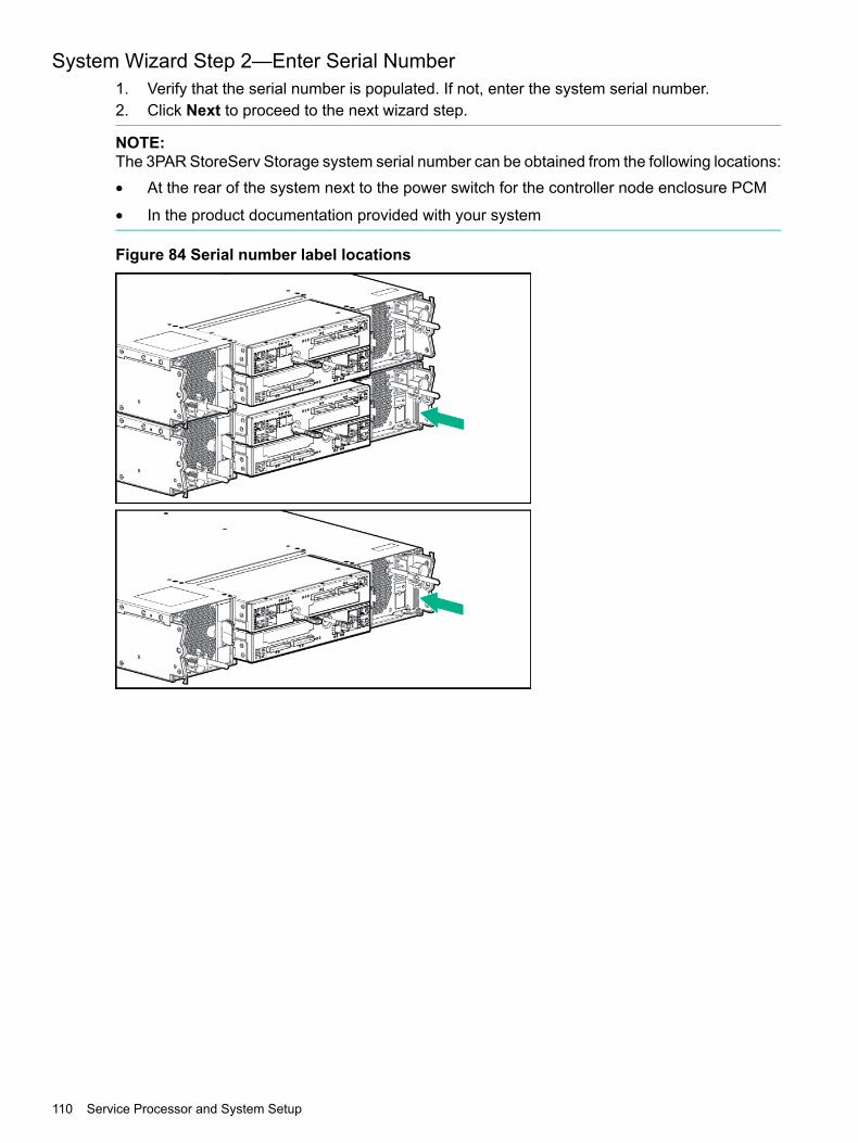
System Wizard Step 2—Enter Serial Number1. Verify that the serial number is populated. If not, enter the system serial number.2. Click Next to proceed to the next wizard step.
NOTE:The 3PAR StoreServ Storage system serial number can be obtained from the following locations:• At the rear of the system next to the power switch for the controller node enclosure PCM
• In the product documentation provided with your system
Figure 84 Serial number label locations
110 Service Processor and System Setup

System Wizard Step 3—Verify Storage System1. Verify that all the system information is correct.2. Click Next to proceed to the next wizard step.
System Wizard Step 4—Configure Networking1. Complete the required fields.
• Storage System Name
• IPv4 Configuration
◦ IPv4 Address
◦ Subnet Mask
◦ Gateway
2. Click Next to proceed to the next wizard step.
System Wizard Step 5—Configuring TimeThe Copy time options from the Service Processor option is selected by default and isautomatically populated with the time and date entered in the 3PAR Service Processor SetupWizard.1. Select the Enter data and time manually option if you want to manually enter the date and
time. If you select Automatic, complete the NTP Server field and click Test to get thespecified NTP time.
2. In the Time Zone section, select the appropriate region.3. Click Next to proceed to the next wizard step.
System Wizard Step 6—Change PasswordThis login profile is used to add this system to the SP and for initial administrative access to thesystem.
NOTE: Passwords for the 3paradm username can include any printable characters and bebetween 6-8 characters in length.
1. Enter a new, secure password for the username 3paradm.2. Click Next to proceed to the next wizard step.
HPE 3PAR Storage System Setup Wizard 111

System Wizard Step 7—Verify ConfigurationThe Verify Configuration page shows all the selected options and this page cannot be modified.
• To modify the selected options, click Prev.
• To proceed to the next wizard step, click Next.
System Wizard Step 8—ProgressThe Progress page shows the setup process and operation status. The Status column indicatesan operation is in progress with an arrow icon and indicates an operation is complete with acheck mark icon.
NOTE: Depending on the type of system configuration, the operation might take up to 30minutes or longer to complete.
1. Verify that the Setup Progress operations have all completed.2. Click Next to proceed to the next wizard step.
System Wizard Step 9—ResultsThe Setup Progress and Results page confirms the system is ready to use. Click Finish.
The system setup wizard has been completed.
NOTE: As of HPE 3PAR OS 3.2.2, additional security has been implemented by using strongpasswords for access by HPE 3PAR service user accounts. By default, time-based strongpasswords are enabled for HPE 3PAR service user accounts. For additional information aboutstrong passwords, see the Using Strong Passwords section in the HPE 3PAR StoreServStorage Concepts Guide.
Post-Installation System TasksThe system setup is now complete. Perform the recommended tasks before using the system:• Validating Remote Support
For more information, see “Validating Remote Support” (page 129).
• Identifying Physical Locations of the Logical Cage NumbersFor more information, see “Identifying Physical Locations of Logical Cage Numbers” (page113)
• Setting up notifications, performing system Health Check and InSplore with SPOCCFor more information, see HPE 3PAR Service Processor Onsite Customer Care User'sGuide.
• Configuring Hosts and creating Virtual Volumes with 3PAR SmartStartFor more information, see HPE 3PAR StoreServ 8000 Storage SmartStart Software User'sGuide.
• Creating LUNs and using the 3PAR StoreServ StorageFor more information, seeHPE 3PAR StoreServ Management Console User Guide at: http://www.hpe.com/info/storage/docs
• Use the checkhealth -detail command, and if there are errors in the report, fix themas needed.
For additional support and other resources, see “Support and other resources” (page 114).
112 Service Processor and System Setup

Identifying Physical Locations of Logical Cage NumbersUse the following CLI commands to identify the physical locations of the logical cage numbers.Enter the numbers into the diagram below, and then store them on the system admin volume byfollowing these instructions.1. On the SPMAINT home page, enter 7 for Interactive CLI for a StoreServ, and then press
ENTER.2. Enter the showcage command to display the drive cage numbers/names3. Enter the locatecage cage<n> command, where cage<n> is the drive cage number/name,
to cause the the LEDs to flash on the front of the drive cage. This will be performed onecage at a time.
4. Once the physical location of the drive cage is identified, make a note of the drive cagenumber on a separate paper for reference during servicing.
NOTE: Table below provides example of drive cage numbering.
4U4U4U
4U4U4U
4U4U4U
4U4U4U
1U1U1U
4U4U4U
4U4U4U
4U4U4U
4U4U4U
Cage rack 2Cage rack 1Node rack
5. Enter setcage position "Rack<xx> Rack-Unit<yy>" cage<n>, where:
• <xx> is the rack designator (R0 is the main rack that has controller nodes, and R1 orracks with higher numbers are expansion cabinets).
• <yy> is the rack-unit number in the rack (e.g., 1 – 50) at the bottom of the drive cage.
• cage <n> is the logical drive cage number/name.6. Enter showcage -d cage<n> to verify the settings.7. Repeat steps 3 through 6 for each drive cage displayed in step 2.8. Enter exit and select X to exit the SPMAINT session.
Post-Installation System Tasks 113

13 Support and other resourcesAccessing Hewlett Packard Enterprise Support
• For live assistance, go to the Contact Hewlett Packard Enterprise Worldwide website:www.hpe.com/assistance
• To access documentation and support services, go to the Hewlett Packard Enterprise SupportCenter website:www.hpe.com/support/hpesc
Information to collect• Technical support registration number (if applicable)
• Product name, model or version, and serial number
• Operating system name and version
• Firmware version
• Error messages
• Product-specific reports and logs
• Add-on products or components
• Third-party products or components
Accessing updates• Some software products provide a mechanism for accessing software updates through the
product interface. Review your product documentation to identify the recommended softwareupdate method.
• To download product updates, go to either of the following:
Hewlett Packard Enterprise Support Center Get connected with updates page:www.hpe.com/support/e-updates
◦
◦ Software Depot website:www.hpe.com/support/softwaredepot
• To view and update your entitlements, and to link your contracts and warranties with yourprofile, go to the Hewlett Packard Enterprise Support Center More Information on Accessto Support Materials page:www.hpe.com/support/AccessToSupportMaterials
IMPORTANT: Access to some updates might require product entitlement when accessedthrough the Hewlett Packard Enterprise Support Center. You must have an HP Passportset up with relevant entitlements.
Websites
LinkWebsite
www.hpe.com/info/enterprise/docsHewlett Packard Enterprise Information Library
www.hpe.com/support/hpescHewlett Packard Enterprise Support Center
114 Support and other resources

LinkWebsite
www.hpe.com/assistanceContact Hewlett Packard Enterprise Worldwide
www.hpe.com/support/e-updatesSubscription Service/Support Alerts
www.hpe.com/support/softwaredepotSoftware Depot
www.hpe.com/support/selfrepairCustomer Self Repair
www.hpe.com/info/insightremotesupport/docsInsight Remote Support
www.hpe.com/info/hpux-serviceguard-docsServiceguard Solutions for HP-UX
www.hpe.com/storage/spockSingle Point of Connectivity Knowledge (SPOCK) Storagecompatibility matrix
www.hpe.com/storage/whitepapersStorage white papers and analyst reports
www.hpe.com/info/storage/docsStorage information library
Customer self repairHewlett Packard Enterprise customer self repair (CSR) programs allow you to repair your product.If a CSR part needs to be replaced, it will be shipped directly to you so that you can install it atyour convenience. Some parts do not qualify for CSR. Your Hewlett Packard Enterprise authorizedservice provider will determine whether a repair can be accomplished by CSR.For more information about CSR, contact your local service provider or go to the CSR website:www.hpe.com/support/selfrepair
Remote supportRemote support is available with supported devices as part of your warranty or contractual supportagreement. It provides intelligent event diagnosis, and automatic, secure submission of hardwareevent notifications to Hewlett Packard Enterprise, which will initiate a fast and accurate resolutionbased on your product’s service level. Hewlett Packard Enterprise strongly recommends thatyou register your device for remote support.For more information and device support details, go to the following website:www.hpe.com/info/insightremotesupport/docs
Documentation feedbackHewlett Packard Enterprise is committed to providing documentation that meets your needs. Tohelp us improve the documentation, send any errors, suggestions, or comments to DocumentationFeedback ([email protected]). When submitting your feedback, include the documenttitle, part number, edition, and publication date located on the front cover of the document. Foronline help content, include the product name, product version, help edition, and publication datelocated on the legal notices page.
Customer self repair 115

A System Illustrated Contents ListThe following components might vary, depending on system configuration:• Appearance of components• Quantity of components• Whether or not the component is included with the system
System Components
LFF (3.5-in) Drive Enclosure (4U)SFF (2.5-in) Drive Enclosure (2U)
Controller Node
I/O module
116 System Illustrated Contents List

Battery for 764 W PCM764 W PCM without Battery
580 W PCM
3.5-inch LFF Drive2.5-inch SFF Drive
System Components 117

3.5-inch LFF Drive Assembly Blank2.5-inch SFF Drive Assembly Blank w/ Yellow TouchPoint
HPE 3PAR Service Processor
3PAR Service Processor
118 System Illustrated Contents List

Rail KitsThe following items are included in the rail kits:
Rail Kits
Right and left 2U rail subassembly (right subassembly shown)
Right and left 4U rail subassembly (right subassembly shown)
M5 screw for middle support bracketM5 shoulder screw for rack mount
M5 cage nutMiddle support bracket
Rail Kits 119

Accessory KitsThe following accessory kits might be included with your system:• Power cords• SAS cables• Cable bundle ties• Hook and loop straps• Product documentation• Various enclosure labels• RJ45 to serial crossover cable• RJ45 to serial cable• CAT5 cable• Ethernet crossover cable• Enclosure rack mounting fasteners• Software kits• Entitlement certificate• Controller node CSR and HBA CSU limitations• 1U filler panels• Link cables• Shipping bracket kit
120 System Illustrated Contents List

B Enhancing Security with Data EncryptionHPE 3PAR Data Encryption security feature allows you to encrypt all specifically formatted driveson the system with an authentication key and the use of self encrypting drives (SEDs) or FederalInformation Processing Standard (FIPS) capable drives.When a Data Encryption license is registered, you must manually enable the encryption featureon the system. When the encryption feature is enabled successfully, all the drives in the systembecome automatically set in an encrypted state.
NOTE: To review the encryption status of individual drives within the system, use the SSMC.
This feature allows you to perform the following encryption-related tasks:• Check encryption status• Enable encryption• Back up an authentication key• Restore an authentication key• Generate a new key• Recover a keyFor more information about enabling the feature, see the HPE 3PAR StoreServ ManagementConsole User Guide at:http://www.hpe.com/info/storage/docs
CAUTION: Hewlett Packard Enterprise recommends retaining all acquired software productlicenses for reference and maintenance purposes. For assistance with licensing, contact HewlettPackard Enterprise Support or see:www.hpe.com/software/licensing
121

C Adding Drives and Expansion Drive Enclosures3PAR StoreServ 8000 Storage products include 3PAR licensing that enables all functionalityassociated with the system. A failure to register the license key might limit access and restrictupgrading of your system. Before you proceed with upgrading, verify that all applicable licensesassociated with the system are registered.For assistance with registering Hewlett Packard Enterprise software licenses, see the HewlettPackard Enterprise Support website:Hewlett Packard Enterprise Support Center (http://www.hpe.com/support/hpesc)There are two types of drive enclosures that are used for expansion:• HPE 3PAR StoreServ Storage SFF 2.5-inch Drive Enclosure:• HPE 3PAR StoreServ Storage LFF 3.5-inch Drive Enclosure:For more information about drive enclosures, see “Installing Enclosures” (page 28).
Information About Drive Enclosure Upgrades• The number of drive enclosures attached to a specific controller node pair should be
determined by the desired RAID set size and HA Cage protection requirements. Driveenclosures should be added and configured to meet the HA Cage protection requirementfor a specific controller node pair, and also consider the RAID set requirement of the customer.
• The distribution of drive enclosures between DP-1 and DP-2 of the controller node shouldbe done to achieve maximum balance across the ports.
• When adding both 2U and 4U drive enclosures, they should be mixed on SAS chains (DP-1and DP-2), added in pairs across controller node pairs on a 4-node system, and balancedacross SAS ports on each controller node pair.
122 Adding Drives and Expansion Drive Enclosures

Drive Enclosure Expansion LimitsNOTE: Drives in the node enclosure are connected internally through DP-1.
Expansion LimitsEnclosure
2-node—9 drive enclosures total8200
• Node DP1 = 4 drive enclosures connected
• Node DP2 = 5 drive enclosures connected
2-node—11 drive enclosures total8400
• Node DP1 = 5 drive enclosures connected
• Node DP2 = 6 drive enclosures connected4-node—22 drive enclosures total
• Node DP1 = 10 drive enclosures connected
• Node DP2 = 12 drive enclosures connected
2-node—19 drive enclosures total8440
• Node DP1 = 9 drive enclosures connected
• Node DP2 = 10 drive enclosures connected4-node—38 drive enclosures total
• Node DP1 = 18 drive enclosures connected
• Node DP2 = 20 drive enclosures connected
2-node—9 drive enclosures total8450
• Node DP1 = 4 drive enclosures connected
• Node DP2 = 5 drive enclosures connected2-node—18 drive enclosures total
• Node DP1 = 8 drive enclosures connected
• Node DP2 = 10 drive enclosures connected
Information About Drive UpgradesYou can install additional drives to upgrade partially populated drive enclosures.
WARNING! If the 3PAR StoreServ Storage is enabled with the Data-at-Rest (DAR) encryptionfeature, only use the self-encrypting drives (SED). Using a non-self-encrypting drive might causeerrors during the upgrade process.
NOTE: SSDs have a limited number of writes that can occur before reaching the SSD's writeendurance limit. This limit is generally high enough so wear out will not occur during the expectedservice life of a 3PAR StoreServ Storage under the great majority of configurations, I/O patterns,and workloads. 3PAR StoreServ Storage tracks all writes to SSDs and can report the percent ofthe total write endurance limit that has been used. This allows any SSD approaching the writeendurance limit to be proactively replaced before they are automatically spared out. An SSD hasreached the maximum usage limit once it exceeds its write endurance limit. Following the productwarranty period, SSDs that have exceeded the maximum usage limit will not be repaired orreplaced under Hewlett Packard Enterprise Support contracts.
Drive Enclosure Expansion Limits 123

• The first expansion drive enclosure added to a system must be populated with the samenumber of drives as the controller node enclosure.
• The drives must be identical pairs.• The same number of drives and type should be added to all of the drive enclosures in the
system.• The minimum addition to a 2-node system without expansion drive enclosures is two identical
drives.• The minimum addition to a 4-node system without expansion drive enclosures is four identical
drives.
3PAR StoreServ 8000 Storage 2.5-inch Drive Enclosure Drive PlacementDrive pairs should be placed in the lowest available slot numbers.
Figure 85 3PAR StoreServ 8000 Storage 2.5-inch Drive Enclosure drive placement order
3PAR StoreServ 8000 Storage 3.5-inch Drive Enclosure Drive PlacementDrive pairs should be populated in columns and in the lowest available vertical slots in thatcolumn.
Figure 86 3PAR StoreServ 8000 Storage 3.5-inch Drive Enclosure drive placement order
NOTE: For optimal utilization and performance, drive quantities and types should be configuredsymmetrically across all drive enclosures in the system.
124 Adding Drives and Expansion Drive Enclosures

Adding DrivesThere are five processes for adding drives:• Checking initial status• Inserting drives• Checking status• Checking progress• Completing the upgrade1. In the SSMC main menu, select Storage Systems > Systems. A list of storage systems is
displayed in the list pane.2. In the Systems filter, select the storage system.3. In the detail pane, select the Configuration view.4. In the Physical Drives panel, click the total physical drives hyperlink. The Physical Drives
screen is displayed.5. In the list pane, select a physical drive to display its properties in the detail pane.6. Install the drives. See “Drives Installation” (page 65).
The display refreshes periodically, and you should see the inserted drives as New in theState column. They are ready to be admitted into the system, which occurs automatically.Within six minutes (depending on the system load and the size of the upgrade), the Stateof the new drives changes to Normal, and the system starts to initialize the chunklets toready for use.Chunklet initialization can take several hours to complete and the output of the availablecapacity is displayed.
NOTE: The system can be used normally, but newly added capacity must be initializedbefore it can be allocated.
The system can be used normally, but newly added capacity must be initialized before it can beallocated.
Adding Drives 125

Adding Expansion Drive EnclosuresBefore you begin: Connect to the service processor and start an SPMAINT session.1. From the SPMAINT home page, enter 7 for Interactive CLI for a StoreServ, and then
choose the system.2. When prompted, enter y to enable maintenance mode for the system.3. Enter checkhealth -detail to verify the current state of the system.4. Install the expansion drive enclosure. See “Enclosures Installation” (page 63).5. Add the storage drives to the front of the drive enclosure bays, starting from bay 0 and
continuing sequentially.. See “Drives Installation” (page 65).6. Connect the mini-SAS cables from the appropriate controller node SAS ports to the I/O
modules in the rear of the drive enclosure according to guidelines. See “System Cabling”(page 79).
7. Label the mini-SAS cables according to guidelines.8. Install the 580 W PCMs into the drive enclosure.9. Connect the power cables to the power supplies and secure them with cable straps.10. On the PCMs, press the power switch to ON.
NOTE: It might take up to five minutes for the drive enclosure to fully power up with thestorage drives available to the cluster.
11. Verify that the drive enclosure, fan module, I/O modules, drive enclosure, power supplies,and drive status LEDs are lit green and operating normally.
12. To verify that the upgrade is successful, issue the showcage command to identify the newcage ID of the newly installed drive enclosure.
13. Enter showport to verify that the connected ports are ready.14. Enter showcage –d followed by <cageID> of the new drive enclosure, to confirm the drives
in the new drive enclosure are spun-up and seen by the system.15. Enter showpd to verify that the new drives appear and the disk state is normal.16. Enter checkhealth -detail to verify the current state of the system.17. Enter exit and press Enter to continue to the main menu. Select X to exit from the 3PAR
Service Processor Menu and to log out of the session.
126 Adding Drives and Expansion Drive Enclosures
D Installing HPE 3PAR Storage Software When HPE 3PARSmartStart is Unavailable
Use the following instructions to manually launch the setup wizards to configure the SP and3PAR StoreServ Storage from a browser if you are not using 3PAR SmartStart or it is unavailable.Review the prerequisites and information about storage and system components beforeproceeding.
PrerequisitesVerify that the following preliminary tasks are completed:• Cabling must be completed, and the system LEDs indicate that cables are properly installed
and the system is operating normally.• The SP is on the same network as the system.• Either the SP is powered on or that the VSP is deployed and powered on.• The 3PAR StoreServ Storage must be connected to the same subnet of the SP, powered
on, and in a non-initialized state for the setup process to verify the 3PAR StoreServ Storage.
Manually Launching the HPE 3PAR Service Processor Setup WizardTo manually launch the 3PAR Service Processor Setup Wizard:1. Launch a web browser.2. Enter the SP URL address. For example:
https://10.0.120.227/sp/SpSetupWizard.html.3. In theUser Name text box, enter setupusr and leave the password blank. You can change
the password in the 3PAR Service Processor Setup Wizard.4. To finish the setup, complete the SP wizard steps by starting with the “SP Wizard Step
1—Welcome” (page 101) section.
Manually Launching the HPE 3PAR Storage System Setup WizardTo manually launch the 3PAR Storage System Setup Wizard:1. Launch a web browser.2. Enter the SP URL address. For example:
https://10.0.120.227/sp/StorageSystemSetupWizard.html.3. In the User Name text box, enter setupusr and enter the password previously set during
the SP setup.4. To finish the setup, complete the System wizard steps by starting with the “System Wizard
Step 1—Welcome” (page 109).
Manually Launching the HPE 3PAR Service Processor Setup Wizard 127

Installing the HPE 3PAR StoreServ Management Console When HPE3PAR SmartStart is Unavailable
To install from the SSMC DVD:1. Insert the SSMC DVD.2. Follow the setup instructions.To download from http://www.hpe.com:1. Download the latest SSMC installation package at:
http://www.hpe.com/support/softwaredepot
NOTE: On Microsoft Windows systems, you must have administrative privileges and bea member of the Administrators group. On Linux systems, you must have superuser access.
2. Install the downloaded software package and follow the setup instructions.
NOTE: The first time you open SSMC after installation, you must set up the user nameand password for the administrator account. Click Set credential in the dialog that appears.After setting the administrator credential, you must log in to the Administrator Console andadd an 3PAR StoreServ Storage system before you can continue.For more information, see the HPE 3PAR StoreServ Management Console AdministratorGuide at:http://www.hpe.com/info/storage/docs
128 Installing HPE 3PAR Storage Software When HPE 3PAR SmartStart is Unavailable

E Validating Remote SupportAfter making any networking changes or if the 3PAR Service Processor Setup Wizard is unableto verify remote support connectivity, use the SPMaint module in SPOCC to test thecommunication with remote support.
NOTE: For a current list of supported browsers for SPOCC, see HPE Single Point ofConnectivity Knowledge (HPE SPOCK):HPE SPOCK (http://www.hpe.com/storage/spock)
Open a supported type of web browser. Enter the SP IP address (https://<SP_IP>) to log on toSPOCC.1. Enter your login credentials. Click Log In.2. Click SPmaint.3. Click Network Configuration.4. Click Test 3PAR Secure Service Collector Server.5. Verify that the SPOCC displaysConnectivity test to HPE 3PAR Secure Service Collector
Server successful.6. Verify that the SP is transferring files successfully by doing the following steps:
a. Click Home to return to the SPOCC home page.The Transfer Status entry indicates the overall status of SP file transfer.
b. To access the SP File Transfer Monitor, click Transfer Status.c. Verify that the SP file transfer is successful:
• The Last transfer status entry should include information about the last SP transfer,including the date and time and a status of Ok.
• TheNumber of files on transfer queue and retry queue should be 0 (zero), whichindicates the SP is currently able to pass files to the transport layer.
• The Service Processor upload queue and SSAgent upload queue show thenumber of files in the queue and should display the date, time, and filename of themost recent file to start uploading.If this queue becomes long, the SP is encountering transfer issues. To remedy thesituation, contact Hewlett Packard Enterprise support.
The SP File Transfer Monitor refreshes every 15 seconds.
129

F TroubleshootingTroubleshooting Duplicate IP Address Issues
If the wizard cannot configure the permanent IP address you entered, because the address isalready in use, do the following:1. Click Stop to stop the Apply Settings process and return to the 3PAR Service Processor
Setup Wizard.2. Click the Prev button until you reach Step 2: SP Networking.3. Determine an available IPv4 address to use for the SP and enter that IP address in the IP
Address text box.4. Click the Next button until you return to Step 7: Apply Settings. (You do not need to enter
any other SP settings again.)The wizard automatically begins to apply the settings again.
If the SP displays a Page Not Found or similar message, the permanent SP IP address youentered is not a valid address. You must set up the SP again.1. Restart the 3PAR Service Processor Setup Wizard:
• If you are using a physical SP, return to the Set IP Address Wizard and set up a new,valid IP address. For more information on determining and assigning the SP IP address,see “Configuring Physical Service Processor IP Address” (page 96).After you have set up the new IP address, use that new permanent IP address to restartthe 3PAR Service Processor Setup Wizard (Enter the URL https://<permanentSP IP address>/sp/SpSetupWizard.html).
• If you are using a VSP, use the temporary SP IP address to restart the 3PAR ServiceProcessor Setup Wizard (enter the URL https://<temporary SP IPaddress>/sp/SpSetupWizard.html).
2. Proceed through the 3PAR Service Processor Setup Wizard, enter your SP settings again.(The SP ID is already set; you do not need to reset the ID.)
3PAR StoreServ Storage Detection IssuesSymptomAfter HPE 3PAR Service Processor Setup Wizard has finished, the 3PAR StoreServ Storagecannot be detected in the 3PAR StoreServ Storage System Setup Wizard.
Possible cause
• The 3PAR StoreServ Storage and the SP are not on the same subnet.• The 3PAR StoreServ Storage serial number was entered incorrectly.• DNS settings were enabled.• There is a network infrastructure issue.
130 Troubleshooting

WorkaroundReinstall the service processor software and begin the service processor initialization using theHPE 3PAR Service Processor Setup Wizard again.
WARNING! During step 3 (Networking) of the 3PAR Service Processor Setup Wizard, do NOTcheck the Enable DNS Support box or enter values forDomain IP Addresses orDNSServer(s).Do NOT configure DNS settings using the HPE 3PAR Service Processor Setup Wizard. Instead,after successfully completing the installation, manually configure DNS using the 3parcust account.To manually configure DNS settings after installation, follow these steps:1. Log on to SPOCC.2. Click theSPMaint tab.3. Select option 2, Network Configuration.4. Select Option 9 — DNS Configuration.
If you do configure DNS using the SP setup wizard, you must reinstall the service processorsoftware and begin the SP initialization using the HPE 3PAR Service Processor Setup Wizardagain.
Remote Support Configuration Failsdev comment: From bug 147508
SymptomThe 3PAR Service Processor Setup Wizard fails. A warning appears:error:Remote Support Configuration failedTo continue Service Processor setup, click Continue.Troubleshooting recommendation:1. Verify the Service Processor is connected to a network that can access the internet.2. If a Proxy Server is required to access the internet verify proxy configuration.3. Verify Firewall and/or Proxy Server rules allow connections to the HP Collector and Global Access Servers.4. For more information on configuring Remote Support, see the HP 3PAR StoreServ 8000 Storage InstallationGuide.NOTE: Until remote connectivity is established to HP 3PAR Central the Service Processor will be unable to sendalerts and files to HP 3PAR Central.
ActionFollow the troubleshooting recommendations shown in the warning, and then click Retry.If the issue persists, click Continue and finish the SP initialization. Then log on to SPOCC, clickthe SPMAINT tab, select Option 2 — Connection Portal Control, and then click Option 7 —Test 3PAR Secure Service Collector Server to ensure that the ping test is successful.
The Service Processor IP Setup Wizard Fails or HangsSymptomWhen you configure the IP address for a PSP using the Service Processor IP Setup wizard, thewizard fails with the following message:"Configuring IP address failed with the following error: Failed to set SP IP address."
WorkaroundWait for 7–10 minutes before clicking the Retry button.
SymptomThe wizard hangs at the Configuring IP address step, and no message appears after morethan 10 minutes.
Remote Support Configuration Fails 131

WorkaroundClose the browser and relaunch the Service Processor IP Setup wizard.
132 Troubleshooting

G System Deinstallation
WARNING! Deinstallation destroys all user data. There is no recovery. This is not the procedurefor regular relocation services (for when the user data is to be saved).
NOTE: If you are planning to reinstall and use the existing license, record the existing licensebefore performing the uninstall by using the showlicense and showlicense -raw commands.
Only use this deinstallation procedure in the following conditions:• To wipe all data and format the drives to prevent access to the old data• To save time to correct an initial installation that was installed incorrectly and that has no
customer data on it
NOTE: In this case, only complete steps 1 to 11 of “Uninstalling the System” (page 134),and then begin again with the system installation procedures in order to re-install the storagesystem.
Before uninstalling a system:• Verify with a system administrator that the system is prepared for shutdown.• Complete the “System Inventory” (page 133).
System InventoryTo complete the system inventory, record the following information for each system to beuninstalled:• Customer name• Site information• System serial numbers. Issue the showinventory CLI command• Software currently running on the system. Issue the following CLI commands to obtain the
listed information:
◦ 3PAR Operating System version — showversion –b –a
◦ Drive cage firmware version — showcage
◦ Disk drive firmware version — showpd –i
◦ 3PAR CBIOS version — shownode -verbose
◦ Features licensed on the array — showlicense
◦ Raw license key for licensed features on the array — showlicense -raw
• Storage system hardware configuration
Number of cabinets◦◦ Number of controller nodes
◦ Amount of data cache in the controller nodes — shownode
◦ Amount of control cache in the controller nodes — shownode
◦ Number and type of Fibre Channel adapters in each node — showport -i
◦ Number of drive cages— showcage (also used above for cage firmware)
System Inventory 133

◦ Number of drive cages
◦ Number of drive magazines — showcage –d
◦ Number and sizes of drives on the magazines — showpd
• Physical condition of system hardware and cabinet (note presence of scratches, dents,missing screws, broken bezels, damaged ports, and other visible anomalies)
• Destination address or addresses and list of the equipment going to each address
NOTE: In this and other chapters, the command-line examples use bold type to indicate userinput and angle bracket (< >) to denote variables. Examples may not match the exact output anyparticular system.
Uninstalling the SystemNOTE: If you are planning to reinstall using the existing license, record the license beforecompleting this uninstall procedure. Use the following commands to record the existing license:showlicense and showlicense -raw.
This section provides instructions for uninstalling a system.1. Connect the laptop to the highest numbered controller node with a serial cable.2. Using a terminal emulator program, such as Putty, set your maintenance laptop console to
the following settings.
ValueSetting
57600Baud rate
8Data bits
NoneParity
1Stop bits
Xon/XoffFlow control
3. Log into the node as the console user.
3PAR(TM) OS <version> <sernum>-<nodeID> ttyS0(none) login: consolePassword: <password>
NOTE: To cancel the process at anytime, press CTRL+C.
4. From the console menu, enter 8 to select Perform a deinstallation.
3PAR Console Menu 1400293-1 3.x.x.xxx
1. Out Of The Box Procedure2. Re-enter network configuration3. Update the CBIOS4. Enable or disable CLI error injections5. Perform a Node-to-Node rescue6. Set up the system to wipe and rerun ootb7. Cancel a wipe8. Perform a deinstallation9. Update the system for recently added hardware (admithw)10. Check system health (checkhealth)11. Load network configuration
134 System Deinstallation

12. Exit> 8
5. A warning message appears to indicate that all data on this system will be lost. Enter y tobegin the deinstallation process and the system reboots.
WARNING:Running this script will result in complete loss of data on this system.Are you sure you want to continue? (y/n)yDeinstallation process will be started in 10 seconds. Once the cluster has rebooted, log back in and rundeinstall_finish.
6. After the system reboots, log on as the console user.
3PAR(TM) InForm(R) OS <version> <sernum>-<nodeID> ttyS0(none) login: consolePassword: <password>
7. From the console menu, enter 8 to select the Perform a deinstallation.8. At this point, all chunklets in the system will be initialized to clear volume data. This is
estimated to take about one to two hours, depending on the capacity of the drives in thesystem. Enter y to begin the deinstallation process to reboot the system.
NOTE: The time required for all chunklet re-initializations during deinstallation dependson the type, size, and number of disks. The estimate of 71 minutes below is an example.NOTE: If you do not wait for the chunklets to be initialized, data still resides on the disksbut cannot be easily accessed. When the chunklets are initialized, zeros are written overthe existing data.If you require additional assistance, contact 3PAR Technical Support.
At this point, all chunklets in the system will be initialized to clear volumedata. This is estimated to take about 71 minutes.
Wait for all chunklets to be initialized? (y/n)y'32 of 2176 chunklets initialized (1%).Est. completion in 70 minutes 0 seconds.
80 of 2176 chunklets initialized (3%).Est. completion in 68 minutes 25 seconds.
9. From the SP Main menu, enter 3 for StoreServ Configuration Management.
1 SP Main3PAR Service Processor Menu
Transfer media: ethernet Transfer status: Ok
Enter Control-C at any time to abort this process
1 ==> SP Control/Status2 ==> Network Configuration3 ==> StoreServ Configuration Management4 ==> StoreServ Product Maintenance5 ==> Local Notification Configuration6 ==> Site Authentication Key Manipulation
Uninstalling the System 135

7 ==> Interactive CLI for an StoreServ
X Exit
10. From the StoreServ Configs menu, enter 4 for Remove a StoreServ, and then pressENTER.
3 StoreServ Configs3PAR Service Processor Menu
Transfer media: ethernet Transfer status: Ok
SP - StoreServ Configuration Manipulation
Enter Control-C at any time to abort this process
1 ==> Display StoreServ information2 ==> Add a new StoreServ3 ==> Modify an StoreServ config parameters4 ==> Remove an StoreServ
X Return to the previous menu
11. Enter x to return to the previous menu.12. From the SP Main menu, enter 1 for SP Control/Status and press ENTER.
1 SP MainHP 3PAR Service Processor Menu
Transfer media: ethernet Transfer status: Ok
Enter Control-C at any time to abort this process
1 ==> SP Control/Status2 ==> Network Configuration3 ==> StoreServ Configuration Management4 ==> StoreServ Product Maintenance5 ==> Local Notification Configuration6 ==> Site Authentication Key Manipulation7 ==> Interactive CLI for a StoreServ
X Exit
13. From the SP Control menu, enter 3 to select Halt SP and press ENTER.
1 SP CONTROLHP 3PAR Service Processor Menu
Transfer media: ethernet Transfer status: Ok
SP Control Functions
Enter Control-C at any time to abort this process
1 ==> Display SP Version2 ==> Reboot SP3 ==> Halt SP4 ==> Stop StoreServ related Processes5 ==> Start StoreServ related Processes6 ==> File Transfer Monitor
136 System Deinstallation

7 ==> SP File Transfer Trigger8 ==> Reset Quiesce state in Transfer process9 ==> Mount a CDROM10 ==> Unmount a CDROM11 ==> SP Date/Time/Geographical Location maintenance12 ==> Manage NTP configuration13 ==> Display SP status14 ==> SP User Access Control15 ==> SP Process Control Parameters16 ==> Maintain SP Software17 ==> SP File Maintenance18 ==> RESERVED19 ==> Request a SPLOR20 ==> Request an MSPLOR21 ==> Run SPCheckhealth22 ==> SP Certificate Information
X Return to previous menu
14. Enter Y to confirm that you want to halt and power off the SP.
1.3.1 SP SHUTDOWNHP 3PAR Service Processor Menu
Transfer media: ethernet Transfer status: Ok
Confirmation
Enter Control-C at any time to abort this process
Halt will power off the SP!Are you certain you want to halt the SP now?
(y or n)
15. Set all power breakers on the PDUs to the OFF position.
CAUTION: For safety precaution, all drive magazines must be properly grounded beforeremoving from the drive chassis.
16. Unplug the system main power cords.17. For system and drive expansion cabinets, coil all main powers cords and strap the cable
along the mounting rails on the side of the cabinet panel. Use a cable tie wrap to secure thecords inside the rack.
18. Disconnect all external connections from the host computer(s) and drive cage expansionracks to the system and remove the cables from the rack. Leave the internal Fibre Channeland SP connections intact if possible.
19. Insert dust plugs into all open system Fibre Channel ports and secure all Fibre Channel,Ethernet, and serial cables remaining inside the rack.
Uninstalling the System 137

H Warranty and regulatory informationFor important safety, environmental, and regulatory information, see Safety and ComplianceInformation for Server, Storage, Power, Networking, and Rack Products, available atwww.hpe.com/support/Safety-Compliance-EnterpriseProducts.
Warranty informationHPE ProLiant and x86 Servers and Optionswww.hpe.com/support/ProLiantServers-Warranties
HPE Enterprise Serverswww.hpe.com/support/EnterpriseServers-Warranties
HPE Storage Productswww.hpe.com/support/Storage-Warranties
HPE Networking Productswww.hpe.com/support/Networking-Warranties
Regulatory InformationRegulatory Model Numbers
For the purpose of regulatory compliance certifications and identification, this product has beenassigned a unique regulatory model number (RMN).The regulatory model number can be found on the product nameplate label, along with all requiredapproval markings and information.When requesting compliance information for this product, always refer to the regulatory modelnumber. The regulatory model number is not the marketing name or model number of the product.Products covered by this manual: Regulatory Model Number (RMN) 3PARA-SV1009.
NOTE: All options and models of the 3PAR StoreServ 8000 Storage family are covered bythis manual.
Safety PrecautionsRetain and follow all product safety and operating instructions. Always refer to the documentation(printed or electronic) supplied with your product. If there is a conflict between this document andthe product documentation, the product documentation takes precedence. Observe all warningson the product and in the operating instructions to reduce the risk of bodily injury, electric shock,fire, and damage to the equipment.
General Precautions
CAUTION: The installation and maintenance of products must be carried out by qualifiedpersonnel.
If the product sustains damage requiring service, disconnect the product from the AC OR DCelectrical outlet and refer servicing to a Hewlett Packard Enterprise authorized service provider.Examples of damage requiring service include:• The power cord, extension cord, or plug has been damaged• Liquid has been spilled on the product or an object has fallen into the product• The product has been exposed to rain or water
138 Warranty and regulatory information

• The product has been dropped or damaged• The product does not operate normally when you follow the operating instructionsTo reduce the risk of personal injury or damage to the product:• Place the product away from radiators, heat registers, stoves, amplifiers, or other products
that produce heat• Never use the product in a wet location• Avoid inserting foreign objects through openings in the product• Move products with casters carefully. Avoid quick stops and uneven surfaces
Symbols on EquipmentThe following symbols might be placed on equipment to indicate the presence of potentiallyhazardous conditions:
Precautions for Maintaining and Servicing ProductsTo reduce the risk of electric shock or damage to the equipment when installing, maintaining, orservicing products, observe the following precautions:• Some products contain power supplies that are capable of producing hazardous energy
levels. Refer to the documentation included with your product to determine whether it containsthese power supplies. The installation of internal options and routine maintenance andservice of this product should be performed by individuals who are knowledgeable aboutthe procedures, precautions, and hazards associated with equipment containing hazardousenergy levels
• Allow the product to cool before removing covers and touching internal components• Do not use conductive tools that could bridge live parts
Regulatory Information 139

• Remove all watches, rings, or loose jewelry when working in hot-plug areas of an energizedserver and storage products
• Do not attempt to defeat safety interlocks (where provided)• Some products have covers or doors to access hot-plug components and might allow access
to hazardous energy circuits or moving fans:
◦ The doors should remain locked during normal operation.OR
◦ The product should be installed in a controlled access location where only qualifiedpersonnel have access to the product
• Power down the equipment and disconnect all AC OR DC power cords before removing anyaccess covers for non-hot-plug areas
• Do not replace non-hot-plug components while power is applied to the product. First, shutdown the product and disconnect all AC OR DC power cords
• Do not exceed the level of repair specified in the procedures in the product documentation.All troubleshooting and repair procedures are detailed to allow only subassembly ormodule-level repair. Because of the complexity of the individual boards and subassemblies,do not attempt to make repairs at the component level or to make modifications to any printedwiring board. Improper repairs can create a safety hazard
• Verify that the AC OR DC power supply branch circuit that provides power to the rack is notoverloaded. This will reduce the risk of personal injury, fire, or damage to the equipment.The total rack load should not exceed 80 percent of the branch circuit rating. Consult theelectrical authority having jurisdiction over your facility wiring and installation requirements
Power CordsTo reduce the risk of electric shock or damage to the equipment:• Use an approved AC OR DC or DC power cord, as appropriate. If you have questions about
the type of power cord to use, contact your Hewlett Packard Enterprise authorized serviceprovider
• If you have not been provided with a power cord for your product or for any AC-poweredoption intended for your product, purchase a power cord that is approved for use in yourcountry
• You must use a power cord rated for your product and for the voltage and current markedon the electrical ratings label of the product. The voltage and current rating of the cord mustbe greater than the voltage and current rating marked on the product
• Do not place objects on power cords or cables. Arrange them so that no one can accidentallystep on or trip over them
• Do not pull on a cord or cable. When unplugging from the electrical outlet, grasp the cordby the plug
• Make sure that the total ampere rating of all products plugged into an extension cord orpower strip does not exceed 80 percent of the ampere ratings limit for the extension cord orpower strip
• Do not disable the power cord grounding plug. The grounding plug is an important safetyfeature
• Plug the power cord into a grounded (earthed) electrical outlet that is easily accessible atall times, or connect to an approved DC source
140 Warranty and regulatory information

Batteries
WARNING! Some Hewlett Packard Enterprise products might contain internal replaceablebattery cells or battery packs. There is risk of fire and burns if the battery pack is not handledproperly. To reduce the risk of personal injury:• Do not attempt to recharge the battery• Do not disassemble, crush, puncture, short external contacts, or dispose of the battery in
fire or water• Replace only with the Hewlett Packard Enterprise spare battery designated for this product.
Dispose of used batteries according to the manufacturer's instructions and local disposalrequirements
• For battery holders (for example, coin cells), observe the correct polarity when changing thebattery/cell. There is a danger of explosion if the battery is installed incorrectly
Power SuppliesHot-plug power supplies are not designed to be removed or installed with AC or DC powerconnected to the power supply. To reduce the risk of electric shock or damage to the equipmentwhen handling hot-plug power supplies:• Install the power supply before connecting the power cord to the power supply• Disconnect the power cord before removing the power supply from the product• If the system has multiple sources of power, you must disconnect all AC or DC power cords
from the power supplies to completely disconnect power from the systemVerify that the external power source connected to your product matches the type of power sourceindicated on the electrical ratings label. If you are not sure of the type of power source required,consult your Hewlett Packard Enterprise authorized service provider or local power company.
Environmental NoticesHewlett Packard Enterprise is committed to providing our customers with information about thechemical substances in our products as needed to comply with legal requirements such asREACH (Regulation EC No 1907/2006 of the European Parliament and the Council). A chemicalinformation report for this product can be found at http://www.hpe.com/info/reach.For Hewlett Packard Enterprise product environmental and safety information and compliancedata, including RoHS and REACH, see www.hpe.com/info/ecodata.For Hewlett Packard Enterprise environmental information, including company programs, productrecycling, and energy efficiency, see www.hpe.com/environment.
Waste Electrical and Electronic Equipment (WEEE) StatementsThe European Union WEEE Directive Page is available at: http://h20564.www2.hpe.com/portal/site/hpesc/public/kb/docDisplay/?docId=c03471072.
Regulatory Information 141

142 Warranty and regulatory information

Regulatory Information 143

Regulatory Compliance Notices
United States of America
Federal Communications Commission NoticePart 15 of the Federal Communications Commission (FCC) Rules and Regulations has establishedRadio Frequency (RF) emission limits to provide an interference-free radio frequency spectrum.Many electronic devices, including computers, generate RF energy incidental to their intendedfunction and are, therefore, covered by these rules. These rules place computers and relatedperipheral devices into the two classes of Class A and Class B, depending upon their intendedinstallation.Class A devices are those that may reasonably be expected to be installed in a business orcommercial environment. Class B devices are those that may reasonably be expected to beinstalled in a residential environment (for example, personal computers). The FCC requiresdevices in both classes to bear a label indicating the interference potential of the device as wellas additional operating instructions for the user.
FCC Class A Rating LabelThe FCC rating label on the device shows the classification of the equipment (Class A). ClassA devices do not have an FCC logo or ID on the label.This equipment has been tested and found to comply with the limits for a Class A digital device,pursuant to Part 15 of the FCC rules. These limits are designed to provide reasonable protectionagainst harmful interference when the equipment is operated in a commercial environment. Thisequipment generates, uses, and can radiate radio frequency energy and, if not installed andused in accordance with the instructions, may cause harmful interference to radio communications.Operation of this equipment in a residential area is likely to cause harmful interference, in whichcase the user will be required to correct the interference at personal expense.
Declaration of ConformityThis device complies with Part 15 of the FCC Rules. Operation is subject to the following twoconditions: (1) this device may not cause harmful interference, and (2) this device must acceptany interference received, including interference that may cause undesired operation.For questions regarding this product, go to the following website: http://www.hpe.com/contact.For questions regarding the FCC declaration, go to the following website:http://www.hpe.com/contact.To identify the product, refer to the part, series, or model number found on the product.
144 Warranty and regulatory information

ModificationsThe FCC requires the user to be notified that any changes or modifications made to this devicethat are not expressly approved by Hewlett Packard Enterprise could void the user's authority tooperate the equipment.
CablesWhen provided, connections to this device must be made with shielded cables with metallicRFI/EMI connector hoods in order to maintain compliance with FCC Rules and Regulations.
Canadian Class A Notice (Avis Canadien)This Class A digital apparatus meets all requirements of the Canadian Interference-CausingEquipment Regulations.Cet appareil numérique de la class A respecte toutes les exigences du Règlement sur le materielbrouilleur du Canada.Such compliance is denoted on the product rating label by “CAN ICES-3 (A) / NMB-3 (A)”.
European Union NoticesThis compliance is indicated by the following conformity marking placed on the product:
This product complies with the following EU directives:• Low Voltage Directive 2006/95/EC• EMC Directive 2004/108/EC• RoHS Directive 2011/65/EUCompliance with these directives implies conformity to applicable harmonized European standards(European Norms) which are listed on the EU Declaration of Conformity issued by Hewlett PackardEnterprise for this product or product family.Certificates can be obtained from the following website:HPE Technical Regulations (http://www.hpe.com/eu/certificates)Hewlett Packard Enterprise GmbH, HQ-TRE, Herrenberger Strasse 140, 71034 Boeblingen,Germany.
Japan
Japanese VCCI-A Notice
Japanese Power Cord Statement
Regulatory Information 145

South Korea
Class A Equipment Notice
Taiwan
Class A Equipment Notice
Belarus Kazakhstan Russia marking
Manufacturer and Local Representative InformationManufacturer information:
• Hewlett Packard Enterprise Company, 3000 Hanover Street, Palo Alto, CA 94304 U.S.Local representative information Russian:• Russia:
• Belarus:
• Kazakhstan:
Local representative information Kazakh:• Russia:
146 Warranty and regulatory information

• Belarus:
• Kazakhstan:
Manufacturing date:The manufacturing date is defined by the serial number.CCSYWWZZZZ (serial number format for this product)Valid date formats include:• YWW, where Y indicates the year counting from within each new decade, with 2000 as the
starting point; for example, 238: 2 for 2002 and 38 for the week of September 9. In addition,2010 is indicated by 0, 2011 by 1, 2012 by 2, 2013 by 3, and so forth.
• YYWW, where YY indicates the year, using a base year of 2000; for example, 0238: 02 for2002 and 38 for the week of September 9.
Regulatory Information 147

RoHS Material Content Declarations
China RoHS Material Content DeclarationChinese version: http://www8.hpe.com/us/en/hp-information/environment/chinarohs.html.English version: http://www8.hpe.com/us/en/hp-information/environment/chinarohs-english.html.
India RoHS Material Content DeclarationThis product complies with the "India E-waste (Management and Handling) Rule 2011" andprohibits use of lead, mercury, hexavalent chromium, polybrominated biphenyls or polybrominateddiphenyl ethers in concentrations exceeding 0.1 weight % and 0.01 weight % for cadmium, exceptfor the exemptions set in Schedule 2 of the Rule.
Turkey RoHS material content declaration
Ukraine RoHS material content declaration
148 Warranty and regulatory information
GlossaryC
CNA converged network adapter
D
DHCP Dynamic Host Configuration ProtocolDNS Domain Name System
E
ESD electrostatic discharge
F
FC Fibre Channel
G
Gb/s Gigabits per second
H
HBA host bus adapter
K
kg kilogram
L
LFF large form factor
N
NL near lineNTP Network Time Protocol
P
PCM power cooling modulePDU power distribution unitPN part number
S
SAS Serial Attached SCSISFF small form factorSKU stock keeping unitSP service processorSSH secure shellSSMC HPE 3PAR StoreServ Management Console
V
VSP virtual service processor
149
Index
Symbols3PAR Service Processor Onsite Customer Care see
SPOCC
Aaccessing
updates, 114acclimatization, 9, 84AFA
all flash array, 65all flash array see AFA
BBelarus Kazakhstan Russia EAC marking, 146bezel
LEDs, 14
Ccabinet
positioning, 55stabilizing, 55unpacking, 55
cabinetscabling, 80
cablingcable restraint shipping brackets, 56expansion cabinets, 80installing cable restraint shipping brackets, 56nodes, 79PDUs, 82power strips, 82power to system, 81removing cable restraint shipping brackets, 58SPs, 81system, 79verifying installation, 56
componentdrive enclosures, 28drives, 29
components, 14, 1162U drive enclosures, 1164U drive enclosures, 116580 W PCM, 117764 W PCM, 117764 W PCM battery, 117accessory kits, 120bezel, 14I/O module, 116I/O modules, 31LFF drive assembly blank, 118node enclosures, 15nodes, 15, 116PCMs, 34PDUs, 39rail kits, 119SFF drive assembly, 117
SFF drive assembly blank, 118SPs, 39, 118VSPs, 39
contacting Hewlett Packard Enterprise, 114controller nodes see nodescustomer self repair, 115
Ddeinstallation
system, 133documentation
providing feedback on, 115drive enclosures, 28
adding, 122numbering, 28numbering LFF enclosure, 28numbering SFF enclosure, 28
drives, 29adding, 122allocating and loading LFF drives, 68allocating and loading SFF drives, 65encryption, 121FIPS, 121illustration, 117installation, 65installing SFF drives, 68LEDs, 30LFF 3.5-inch, 14LFF loading order, 68loading LFF avoid practices guidelines, 70loading LFF best practices guidelines, 69loading SFF avoid practices guidelines, 66loading SFF best practices guidelines, 66SEDs, 121SFF 2.5-inch, 14SFF loading order, 65
EEAC marking
Belarus Kazakhstan Russia, 146enclosures
2U drive enclosure illustration, 1164U drive enclosure illustration, 116bezel, 14bezel LEDs, 14installation, 63installing, 63unpacking, 59
encryptiondrive data, 121
EuroAsian Economic Commission (EAC), 146
FFederal Information Processing Standard see FIPSFIPS
Federal Information Processing Standard, 121
150 Index

HHPE 3PAR SmartStart
prerequisites, 98system setup, 99
HPE 3PAR StoreServ Management Console see SSMC
II/O modules, 31
illustration, 116LEDs, 31numbering LFF drive enclosure, 32numbering SFF drive enclosure, 32
Installationchecklist, software, 86checklists, 86
installationcabinet positioning, 55cabinet unpacking, 55cable restraint shipping brackets, 56components in existing rack, 59drives, 65enclosures, 63inspecting the packaging, 12options, 13PDUs, 42post-install tasks, 112precautions, 10rail kit, 59SmartStart prerequisites, 98SP setup wizard, 100SPs, 72system hardware checklist, 13system setup wizard, 108tools, 10validating remote support, 129
Installingsoftware without wizard, 127
installingcable restraint shipping brackets, 56enclosures, 63PDUs, 46PDUs 1U/2U, 50SFF drives, 68SP rail kit, 74SPs, 74
Llarge form factor see LFFLEDs
580 W PCM, 37764 W PCM, 35bezel, 14drives, 30I/O modules, 31nodes, 27SPs, 40verifying status, 85
LFFlarge form factor 3.5-inch drive, 14
licensesredeeming and registering, 12
Nnodes, 15
controller nodes, 14enclosure, 15illustration, 116LEDs, 27numbering 2-node system, 16numbering 4-node system, 16ports, 17
Oopen virtualization format see OVFOVF
open virtualization format, 90
PPCMs
580 W, 34580 W LEDs, 37764 W, 34764 W LEDs, 35illustrations, 117numbering 2-node enclosure, 36numbering 4-node enclosure, 36numbering LFF drive enclosure, 38numbering SFF drive enclosure, 38
PDUs, 39cabling, 82configurations, 44installation, 42installation precautions, 42installing, 46installing 1U/2U, 50securing cable retention bracket, 54
power cooling module see PCMspower distribution units see PDUsP 3PAR SmartStart
troubleshooting, 130
Rracks
installation precautions, 12installing components, 59types, 73
rail kitsillustration, 119
regulatory compliance, 42regulatory information, 138
Turkey RoHS material content declaration, 148Ukraine RoHS material content declaration, 148
remote support, 115removing
cable restraint shipping brackets, 58RPS
redundant power supply, 39
151

Ssafety, 42
power safety precautions, 42preventing electrostatic discharge, 11
securitydata encryption, 121data encryption license, 121
SEDsself encrypting drives, 121
self encrypting drives see SEDsservice processors see SPsSFF
small form factor 2.5-inch drive, 14small form factor see SFFsolid state drive see SSDsSPOCC
3PAR Service Processor Onsite Customer Care, 88reset SP password, 106
SPSsingle power supply, 39
SPs, 39cabling, 81connecting IP address, 96connecting to, 96illustration, 118initialization, 90installation, 72installing, 74LEDs, 40mounting kit, 72setup, 98
SSDssolid state drives, 65
SSMCHPE 3PAR StoreServ Management Console, 121
supportHewlett Packard Enterprise, 114
systemacclimating, 84acclimatization, 9cabling, 79cabling power, 81components, 116factory-integrated setup, 55general site planning, 7identifying physical locations of logical cage numbers,
113installation in existing rack, 59inventory, 133post-install tasks, 112powering on, 85pre-installation planning, 7repositioning, 83setup, 98setup wizard, 108shipping containers, 9SmartStart setup, 99uninstalling, 134unpacking enclosures, 59
verifying LED status, 85verifying power connections, 83verifying setup, 83
Ttroubleshooting, 130
duplicate IP address issues, 130HPE 3PAR SmartStart, 130IP address configuration, 131the Service Processor IP Setup wizard fails or hangs,
131Turkey RoHS material content declaration, 148
UUkraine RoHS material content declaration, 148uninstalling
system, 134updates
accessing, 114
Vvirtual service processors see VSPsVSPs, 39
connecting to, 90deploying OVF file, 92establishing IP address, 92prerequisites for using, 90
Wwarranty information, 138
Hewlett Packard Enterprise Enterprise servers, 138Hewlett Packard Enterprise Networking products, 138Hewlett Packard Enterprise Storage products, 138HPE ProLiant and x86 Servers and Options, 138
websites, 114customer self repair, 115
wizardsSP setup wizard, 100system setup wizard, 108
152 Index