Embed Size (px)
Citation preview
HPE 3PAR StoreServ Sparing Technologies Contents Executive summary ................................................................................................................................................................................................................................................................. 2
Definitions ........................................................................................................................................................................................................................................................................................ 2
Spare space .................................................................................................................................................................................................................................................................................... 2
Distributed sparing ........................................................................................................................................................................................................................................................... 3
Rebuilds....................................................................................................................................................................................................................................................................................... 3
How much spare space do I need? ........................................................................................................................................................................................................................... 3
HPE 3PAR StoreServ 10000 .................................................................................................................................................................................................................................. 3
Spare policy—schemes ................................................................................................................................................................................................................................................. 4
Spare rate................................................................................................................................................................................................................................................................................... 4
Sparing algorithms defined .............................................................................................................................................................................................................................................. 4
Nearline (NL) drives are special ............................................................................................................................................................................................................................ 5
Adaptive sparing........................................................................................................................................................................................................................................................................ 5
Adaptive Sparing examples ...................................................................................................................................................................................................................................... 6
Spare space implementation: admithw ................................................................................................................................................................................................................. 7
How does it all work?............................................................................................................................................................................................................................................................. 7
Evacuating drives ............................................................................................................................................................................................................................................................... 8
Viewing spare space ........................................................................................................................................................................................................................................................ 8
Changing spare space policy ................................................................................................................................................................................................................................... 9
Sparing performance ......................................................................................................................................................................................................................................................... 10
System performance during sparing ............................................................................................................................................................................................................ 10
Sizing: NinjaSTARS .............................................................................................................................................................................................................................................................. 12
Predictive drive failures ................................................................................................................................................................................................................................................... 13
Conclusion ................................................................................................................................................................................................................................................................................... 14
Resources ..................................................................................................................................................................................................................................................................................... 14
Technical white paper
Technical white paper Page 2
Executive summary HPE 3PAR storage arrays are designed for high availability and include many features that enable the array to maintain availability when a failure occurs and one of these features is the sparing architecture.
The HPE 3PAR StoreServ sparing policies provide space and processes to handle the various failure modes of solid state media as well as the mechanical failures of spinning media. HPE 3PAR StoreServ sparing architecture provides many-to-many rebuilds resulting in speedy recovery which limits the exposure of a second failure occurring while recovering from the first failure. The reduced recovery time limits the exposure of a second failure occurring while recovering from the first failure.
HPE 3PAR StoreServ sparing policies and algorithms are an integral part of the HPE 3PAR StoreServ operating system and are a core component of every HPE 3PAR storage array. This white paper explains the sparing policies and algorithms of HPE 3PAR StoreServ arrays that allow applications to achieve maximum benefit.
Definitions • Chunklet: Physical disks are divided into chunklets. Each chunklet occupies contiguous space on a disk. Chunklets on HPE 3PAR StoreServ
10000 and 7000 and later storage systems are 1 GB.
• Sparing policy: HPE 3PAR StoreServ policy which manages the sparing process. The policies include user options (schemes) and algorithms to reserve spare chunklets and move data to these chunklets when necessary.
• Devtype: A category of device such as SSD, FC, and NL.
– SSD = Solid State Drive
– FC = Fast Class (10K and 15K RPM spinning media devices)
– NL = Nearline (7.2K spinning media devices)
• Scheme: Sparing policy configuration options that include:
– Default
– Minimal
– Maximal
– Custom
• Relocation: The movement of data in a chunklet from one place, such as a failing drive, to another place, such as a spare chunklet on a good drive.
• SSD: Solid State Drive. Non-volatile flash memory chips packaged in a hard disk form factor. Functions as a disk device, but with the properties of flash including higher performance, increased density and lower latency compared to traditional spinning media.
Spare space Storage arrays today have a variety of approaches to address the basic challenge of how to keep an array running when failures occur. The basic building block of data protection has been RAID for a long time and this key element continues today in various implementations. A key element of data protection is sparing. Sparing is a process by which a RAID storage system restores resilience to data stored across a collection of disks after a single disk fails. All RAID arrays in the industry today implement some type of sparing algorithm.
Traditionally, storage array vendors have architected spare disks as part of array design. Spare disks, sometimes called hot spares or dedicated spares, are extra disks that are standing by waiting for a failure to occur before they are utilized. When a primary disk fails, the spare disk is immediately called into service to replace the failed disk and missing data is rebuilt onto the spare disk.
One problem with the dedicated spare disk approach is loss of performance. A dedicated spare disk is not used until the failure of another disk. The space, power, potential performance, and capital used to purchase the disk are all wasted resources the majority of the life of the disk. HPE 3PAR has addressed these shortcomings by virtualizing the function of the spare disk called distributed sparing.
Technical white paper Page 3
Distributed sparing Using dedicated spare drives is wasteful; with spinning media, dedicated spares represent capacity and performance that can’t be used by the system unless the system suffers a drive failure. For solid state media, the issue is compounded by the limited endurance of flash—dedicating a drive for sparing means the flash cells on that drive cannot be used for wear-leveling which reduces the overall lifespan of every solid state drive in the system. HPE 3PAR StoreServ systems combat these all-too-common issues by leveraging the virtualized nature of 3PAR to provide distributed sparing.
HPE 3PAR StoreServ systems divide physical disks into chunklets when they are admitted to the system. Most chunklets on each disk are used to hold user data while a small number of chunklets are designated as spares. This distributed spare space serves the same function as a dedicated spare, but provides the performance benefit of having all drives in the system active.
Rebuilds Another benefit of distributed sparing is many-to-many rebuilds. When a drive fails, a process begins to recover the lost redundancy by rebuilding the data that was on the failed drive. All used chunklets on the failed drive are rebuilt on spare chunklets on the remaining drives. Unlike some sparing implementations, 3PAR StoreServ only rebuilds space from the failed drive that was actually in use resulting in faster rebuilds and less spare space used to rebuild any given drive. Failed chunklets are reconstructed by reading data from the remaining chunklets in the virtual RAID set and computing the missing data from the parity information where necessary.
The rebuild process chooses a target spare chunklet using several criteria. These criteria are prioritized to maintain the same level of performance and availability as the source chunklet if possible. The following list shows the priority used to select a spare chunklet.
1. Locate a chunklet on the same type of drive (e.g. NL, FC).
2. Maintain the same HA characteristics as the failed chunklet (e.g. HA cage, HA magazine).
3. Keep the chunklet on the same node as the failed drive.
The best case is when spare chunklets are on the same node as the failed drive with the same availability characteristics. When spare chunklets with this criteria are not available, free chunklets with the same characteristics are considered. During the sparing process if the number of free chunklets used exceeds a threshold set in the HPE 3PAR StoreServ OS, consideration will be given to spare chunklets on another node. This will help keep the array balanced.
The sparing algorithm will locate target chunklets spread around many different disks. The disk being rebuilt will also have its remaining good chunklets spread among many disks creating a many-to-many rebuild.
How much spare space do I need? Reserved spare space is not used for user data during normal operations, so the system needs just enough to handle any failures, but no more. When reserving spare space, there are several factors to consider, but the defaults often work best.
Spare space is used to hold data from a failing or failed drive. The minimum space needed is the capacity of one drive. Since the number of concurrent drive failures is related to the number of drives in the array, expect to configure more spare space when there are more drives.
HPE 3PAR StoreServ 10000 Another factor to consider is the architecture of the array. HPE 3PAR StoreServ 10000 arrays use a magazine that holds four drives as part of the physical hardware. When a failed drive must be replaced, the entire magazine must be removed to access the failed drive. The service process will relocate the used chunklets from the three good drives in the magazine to spare chunklets before the magazine is removed. Since a minimum of four drives will be physically removed from the system during drive replacement, HPE recommends a minimum spare space on these systems of four drives.
There is an option when replacing a failed drive on a HPE 3PAR StoreServ 10000 to use log space to hold write I/Os to the three good drives during drive replacement. This option is not always possible, but when it is possible, the time to copy three drives worth of space to spare chunklets can be saved. This makes the drive replacement process faster.
Writes made to the three good drives in the magazine are held in log space while they are unavailable because of the drive replacement procedure. When the drive replacement procedure is completed, the data is replayed from the log space to the drives. This option can save considerable time, but is not always possible.
Technical white paper Page 4
Spare policy—schemes The HPE 3PAR StoreServ OS provides four user-settable options relating to spare space sizing. These options, referred to as schemes, are:
• Minimal
• Default
• Maximal
• Custom
Best practice: The default spare policy provides the best balance of reserved spare space and usable space and is the HPE recommended option for most configurations.
The spare policy is set when the system is installed. The policy can be changed using HPE 3PAR StoreServ CLI commands. The spare policy is set with the HPE 3PAR StoreServ CLI setsys command. The spare policy is implemented with the HPE 3PAR StoreServ CLI admithw command.
The first three sparing policies—Minimal, Default and Maximal—are automatically managed by the HPE 3PAR StoreServ OS, while the custom setting requires the administrator to actively manage spare space. The custom setting requires the use of the HPE 3PAR StoreServ CLI commands createspare, removespare, and showspare.
Note The use of Custom sparing is only recommended when initiated by HPE support.
HPE 3PAR StoreServ CLI commands used to manage sparing are documented in the HPE 3PAR Command Line Interface Reference manual.
The HPE 3PAR StoreServ CLI setsys command allows many system parameters to be set. The specific form of the command to set the sparing policy is shown below. This example sets the sparing policy to ‘Default’.
lab-xx cli% setsys SparingAlgorithm Default
Spare rate A key parameter in the spare policy is the spare rate. The spare rate is a target amount of space to set aside for sparing expressed relative to the number of disks of a given type in the system. A spare rate of 24, for example, sets target spare space equal to the size of one drive for every 24 drives in the array.
The spare rate is defined based on the hardware configuration in the array as follows:
• Spare rate = 40 if there are any magazines present in the array (e.g. 10,000)
• Spare rate = 24 for all others such as 8450, 20450, etc.
NOTE The two terms, spare rate and sparing rate, are similar but different. Please don’t confuse them. The term spare rate as used here represents the ratio of spare space to total space as just discussed. The term sparing rate is the rate at which we can move data to reconstruct a failed drive and is dependent on many factors, including array load and the number of drives.
Sparing algorithms defined 3PAR sparing algorithms apply to all drive types, but HPE’s patented Adaptive Sparing technology will determine spare space for most SSD configurations. Adaptive Sparing, discussed later in this paper, will set aside a minimum amount of space per SSD as spare space to support increased write performance and endurance.
The spare option is set for the entire array and applied to each disk type (SSD, FC, NL). The following spare space options apply to all spinning media and some smaller SSD configurations.
Technical white paper Page 5
• Default: roughly 2.5 percent with minimums Small configurations (e.g. 8000’s with less than 48 disks, 20000’s with less than 80 disks) have a spare space target equal to the size of two of the largest drives of the type being spared.
• Minimal: roughly 2.5 percent without minimums Minimal is the same as default except for small configurations. When the configuration is small, minimal will only set aside spare space equal to one of the largest drives (compared to two for default) of the type being sized.
• Maximal: one disk’s worth in every cage Spare space is calculated as the space of the largest drive of the drive type being sized for each disk cage.
• Custom: Implemented manually by the administrator using the createspare, showspare, and removespare commands.
Nearline (NL) drives are special Nearline (NL) drives get special treatment in calculating spare space using the automatically managed options (Default, Minimal, Maximal). In general, spare space should be created and used in each drive type to address the spare needs of that drive type. There is a special case, however, where FC spare space can be used to serve the spare needs of the NL tier. FC disks perform better than NL drives in general so there should be no negative performance impact from relocating chunklets of a failing NL drive to spare space on FC disks.
Spare space is calculated as a number of spare chunklets and is calculated for each drive type starting with FC drives. Spare space for NL drives is calculated as described above, then it is reduced by the number of spare chunklets in the FC tier. For example, if 5,000 spare chunklets are needed in the FC tier and 8,000 spare chunklets for the NL tier, only the incremental need of 3,000 (8,000–5,000) spare chunklets will be allocated on the NL tier.
Adaptive sparing HPE Adaptive Sparing is a patented way to fully flash-optimize sparing. HPE 3PAR has always addressed the need for spare space better than other architectures through distributed sparing and Adaptive Sparing extends this leadership to solid state media.
NAND flash overprovisioning is key to managing endurance, but it’s expensive and limits the stated capacity of the SSD to less than the quantity of flash chips in the device. Overprovisioning is in many ways the opposite of thin provisioning (TPVV). Thin provisioning allows HPE 3PAR StoreServ arrays to tell a host a particular VV has more capacity available than is currently written (the host believes there is more storage than is currently provisioned). SSD overprovisioning reports less capacity than the sum of the flash chips. A 480 GB SSD, for example, might have a total of 576 GB of flash chips where the additional 96 GB (20 percent) is used for over provisioning.
Adaptive Sparing is the result of collaboration between Hewlett Packard Enterprise and SSD suppliers to return system-level reserved spare space to the SSD’s controller, allowing it to be used as drive-level overprovisioning space for managing endurance and performance. Current NAND flash technology has a property where write operations wear the flash chips and they eventually wear out. Returning spare space back to the drive means that SSD endurance is guaranteed by HPE in HPE 3PAR StoreServ arrays for five years through an unconditional drive warrantee.
Technical white paper Page 6
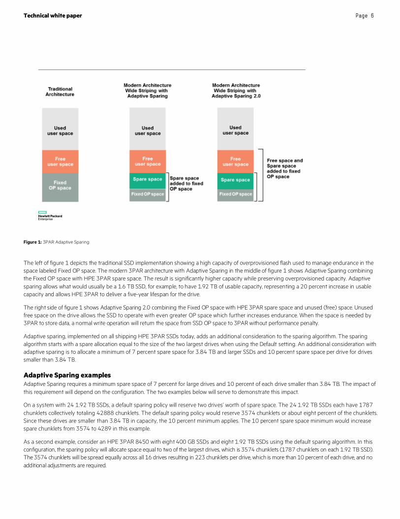
Figure 1: 3PAR Adaptive Sparing
The left of figure 1 depicts the traditional SSD implementation showing a high capacity of overprovisioned flash used to manage endurance in the space labeled Fixed OP space. The modern 3PAR architecture with Adaptive Sparing in the middle of figure 1 shows Adaptive Sparing combining the Fixed OP space with HPE 3PAR spare space. The result is significantly higher capacity while preserving overprovisioned capacity. Adaptive sparing allows what would usually be a 1.6 TB SSD, for example, to have 1.92 TB of usable capacity, representing a 20 percent increase in usable capacity and allows HPE 3PAR to deliver a five-year lifespan for the drive.
The right side of figure 1 shows Adaptive Sparing 2.0 combining the Fixed OP space with HPE 3PAR spare space and unused (free) space. Unused free space on the drive allows the SSD to operate with even greater OP space which further increases endurance. When the space is needed by 3PAR to store data, a normal write operation will return the space from SSD OP space to 3PAR without performance penalty.
Adaptive sparing, implemented on all shipping HPE 3PAR SSDs today, adds an additional consideration to the sparing algorithm. The sparing algorithm starts with a spare allocation equal to the size of the two largest drives when using the Default setting. An additional consideration with adaptive sparing is to allocate a minimum of 7 percent spare space for 3.84 TB and larger SSDs and 10 percent spare space per drive for drives smaller than 3.84 TB.
Adaptive Sparing examples Adaptive Sparing requires a minimum spare space of 7 percent for large drives and 10 percent of each drive smaller than 3.84 TB. The impact of this requirement will depend on the configuration. The two examples below will serve to demonstrate this impact.
On a system with 24 1.92 TB SSDs, a default sparing policy will reserve two drives’ worth of spare space. The 24 1.92 TB SSDs each have 1787 chunklets collectively totaling 42888 chunklets. The default sparing policy would reserve 3574 chunklets or about eight percent of the chunklets. Since these drives are smaller than 3.84 TB in capacity, the 10 percent minimum applies. The 10 percent spare space minimum would increase spare chunklets from 3574 to 4289 in this example.
As a second example, consider an HPE 3PAR 8450 with eight 400 GB SSDs and eight 1.92 TB SSDs using the default sparing algorithm. In this configuration, the sparing policy will allocate space equal to two of the largest drives, which is 3574 chunklets (1787 chunklets on each 1.92 TB SSD). The 3574 chunklets will be spread equally across all 16 drives resulting in 223 chunklets per drive, which is more than 10 percent of each drive, and no additional adjustments are required.
Technical white paper Page 7
Adaptive Sparing offers many benefits including larger usable space and reduced cost. As we have just seen, the HPE 3PAR sparing policy incorporates Adaptive Sparing into its policy without the requirement for user interaction.
Spare space implementation: admithw When one of the automatically managed sparing policies are set with the setsys command, it does not immediately change any spare space on the system. Implementing the sparing policy is done with the admithw command. As its names suggests, it is intended for execution when new hardware is added to the array, but it can also be run to implement a new sparing policy.
NOTE The admithw command can be run in a production environment to change the sparing scheme. The back-end workload to implement a sparing policy change is low.
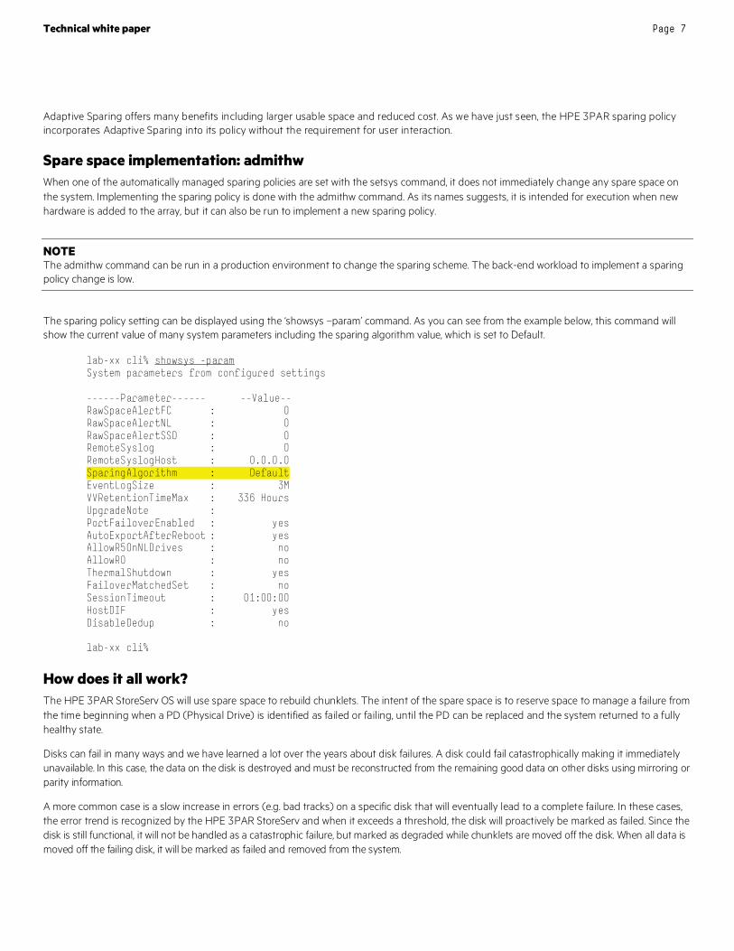
The sparing policy setting can be displayed using the ‘showsys –param’ command. As you can see from the example below, this command will show the current value of many system parameters including the sparing algorithm value, which is set to Default.
lab-xx cli% showsys -param System parameters from configured settings ------Parameter------ --Value-- RawSpaceAlertFC : 0 RawSpaceAlertNL : 0 RawSpaceAlertSSD : 0 RemoteSyslog : 0 RemoteSyslogHost : 0.0.0.0 SparingAlgorithm : Default EventLogSize : 3M VVRetentionTimeMax : 336 Hours UpgradeNote : PortFailoverEnabled : yes AutoExportAfterReboot : yes AllowR5OnNLDrives : no AllowR0 : no ThermalShutdown : yes FailoverMatchedSet : no SessionTimeout : 01:00:00 HostDIF : yes DisableDedup : no lab-xx cli%
How does it all work? The HPE 3PAR StoreServ OS will use spare space to rebuild chunklets. The intent of the spare space is to reserve space to manage a failure from the time beginning when a PD (Physical Drive) is identified as failed or failing, until the PD can be replaced and the system returned to a fully healthy state.
Disks can fail in many ways and we have learned a lot over the years about disk failures. A disk could fail catastrophically making it immediately unavailable. In this case, the data on the disk is destroyed and must be reconstructed from the remaining good data on other disks using mirroring or parity information.
A more common case is a slow increase in errors (e.g. bad tracks) on a specific disk that will eventually lead to a complete failure. In these cases, the error trend is recognized by the HPE 3PAR StoreServ and when it exceeds a threshold, the disk will proactively be marked as failed. Since the disk is still functional, it will not be handled as a catastrophic failure, but marked as degraded while chunklets are moved off the disk. When all data is moved off the failing disk, it will be marked as failed and removed from the system.

Technical white paper Page 8
Evacuating drives The process of moving chunklets off a disk is called evacuating the drive. This process is used when addressing a failing, but not yet failed, disk. This process can take considerable time, depending on how much data must be evacuated off the drive and how much I/O is active on the back-end of the array.
NOTE Some service commands also cause drives to be evacuated. These commands are intended for service engineers (e.g. TS).
Viewing spare space As mentioned above, the sparing policy can be displayed using the showsys –param command. The current spare space usage can be displayed with the showspare command. Showspare will list all spare chunklets as well as free chunklets that are in use as a spare. Since most systems will have many spare chunklets and the showspare command will list each one, the output from the showspare command may be quite lengthy. You may wish to use the cmore command with the showspare command to cause the output to be paged for better display. Here is an example of the showspare command from a typical system where no spare chunklets are in use:
Lab-xx cli% showspare Pdid Chnk LdName LdCh State Usage Media Sp Cl From To 0 257 ---- --- none available valid Y Y --- --- 0 258 ---- --- none available valid Y Y --- --- 0 259 ---- --- none available valid Y Y --- --- 0 260 ---- --- none available valid Y Y --- --- 0 261 ---- --- none available valid Y Y --- --- 0 262 ---- --- none available valid Y Y --- --- 0 263 ---- --- none available valid Y Y --- --- 0 264 ---- --- none available valid Y Y --- --- 0 265 ---- --- none available valid Y Y --- --- 0 266 ---- --- none available valid Y Y --- --- 0 267 ---- --- none available valid Y Y --- --- 0 268 ---- --- none available valid Y Y --- --- 0 269 ---- --- none available valid Y Y --- --- 0 270 ---- --- none available valid Y Y --- --- 1 257 ---- --- none available valid Y Y --- --- 1 258 ---- --- none available valid Y Y --- ---
Here is an example from a 7400c with a failed drive. This example uses the –used option to only show chunklets currently in use as spare chunklets.
Lab-xx cli% showspare -used Pdid Chnk LdName LdCh State Usage Media Sp Cl From To
12 1616 tp-3-sd-0.13 10 normal ld valid Y N 2:92 --- 14 1609 tp-3-sd-0.1 24 normal ld valid Y N 2:6 --- 14 1610 tp-3-sd-0.1 192 normal ld valid Y N 2:15 --- 14 1611 tp-3-sd-0.5 112 normal ld valid Y N 2:40 --- 14 1612 tp-3-sd-0.11 42 normal ld valid Y N 2:80 --- 16 1609 tp-3-sd-0.1 0 normal ld valid Y N 2:5 --- 16 1610 tp-3-sd-0.1 181 normal ld valid Y N 2:14 --- 16 1611 tp-3-sd-0.3 114 normal ld valid Y N 2:27 ---
--------------------------------------------------------------- Total chunklets: 8
Technical white paper Page 9
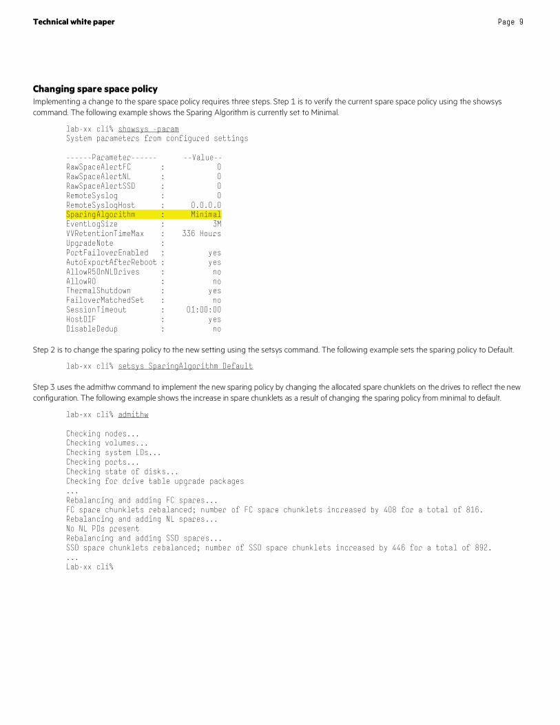
Changing spare space policy Implementing a change to the spare space policy requires three steps. Step 1 is to verify the current spare space policy using the showsys command. The following example shows the Sparing Algorithm is currently set to Minimal.
lab-xx cli% showsys -param System parameters from configured settings ------Parameter------ --Value-- RawSpaceAlertFC : 0 RawSpaceAlertNL : 0 RawSpaceAlertSSD : 0 RemoteSyslog : 0 RemoteSyslogHost : 0.0.0.0 SparingAlgorithm : Minimal EventLogSize : 3M VVRetentionTimeMax : 336 Hours UpgradeNote : PortFailoverEnabled : yes AutoExportAfterReboot : yes AllowR5OnNLDrives : no AllowR0 : no ThermalShutdown : yes FailoverMatchedSet : no SessionTimeout : 01:00:00 HostDIF : yes DisableDedup : no
Step 2 is to change the sparing policy to the new setting using the setsys command. The following example sets the sparing policy to Default.
lab-xx cli% setsys SparingAlgorithm Default
Step 3 uses the admithw command to implement the new sparing policy by changing the allocated spare chunklets on the drives to reflect the new configuration. The following example shows the increase in spare chunklets as a result of changing the sparing policy from minimal to default.
lab-xx cli% admithw Checking nodes... Checking volumes... Checking system LDs... Checking ports... Checking state of disks... Checking for drive table upgrade packages ... Rebalancing and adding FC spares... FC spare chunklets rebalanced; number of FC spare chunklets increased by 408 for a total of 816. Rebalancing and adding NL spares... No NL PDs present Rebalancing and adding SSD spares... SSD spare chunklets rebalanced; number of SSD spare chunklets increased by 446 for a total of 892. ... Lab-xx cli%
Technical white paper Page 10
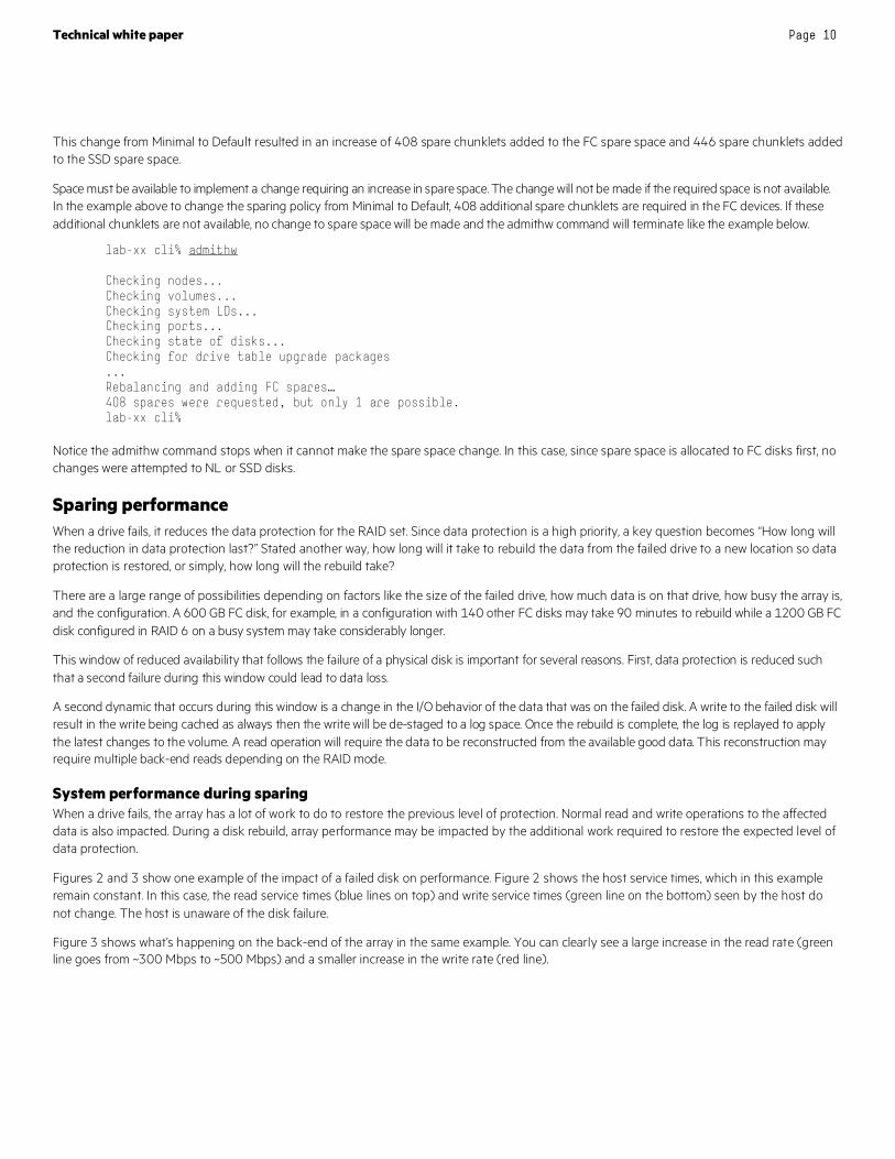
This change from Minimal to Default resulted in an increase of 408 spare chunklets added to the FC spare space and 446 spare chunklets added to the SSD spare space.
Space must be available to implement a change requiring an increase in spare space. The change will not be made if the required space is not available. In the example above to change the sparing policy from Minimal to Default, 408 additional spare chunklets are required in the FC devices. If these additional chunklets are not available, no change to spare space will be made and the admithw command will terminate like the example below.
lab-xx cli% admithw Checking nodes... Checking volumes... Checking system LDs... Checking ports... Checking state of disks... Checking for drive table upgrade packages ... Rebalancing and adding FC spares… 408 spares were requested, but only 1 are possible. lab-xx cli%
Notice the admithw command stops when it cannot make the spare space change. In this case, since spare space is allocated to FC disks first, no changes were attempted to NL or SSD disks.
Sparing performance When a drive fails, it reduces the data protection for the RAID set. Since data protection is a high priority, a key question becomes “How long will the reduction in data protection last?” Stated another way, how long will it take to rebuild the data from the failed drive to a new location so data protection is restored, or simply, how long will the rebuild take?
There are a large range of possibilities depending on factors like the size of the failed drive, how much data is on that drive, how busy the array is, and the configuration. A 600 GB FC disk, for example, in a configuration with 140 other FC disks may take 90 minutes to rebuild while a 1200 GB FC disk configured in RAID 6 on a busy system may take considerably longer.
This window of reduced availability that follows the failure of a physical disk is important for several reasons. First, data protection is reduced such that a second failure during this window could lead to data loss.
A second dynamic that occurs during this window is a change in the I/O behavior of the data that was on the failed disk. A write to the failed disk will result in the write being cached as always then the write will be de-staged to a log space. Once the rebuild is complete, the log is replayed to apply the latest changes to the volume. A read operation will require the data to be reconstructed from the available good data. This reconstruction may require multiple back-end reads depending on the RAID mode.
System performance during sparing When a drive fails, the array has a lot of work to do to restore the previous level of protection. Normal read and write operations to the affected data is also impacted. During a disk rebuild, array performance may be impacted by the additional work required to restore the expected level of data protection.
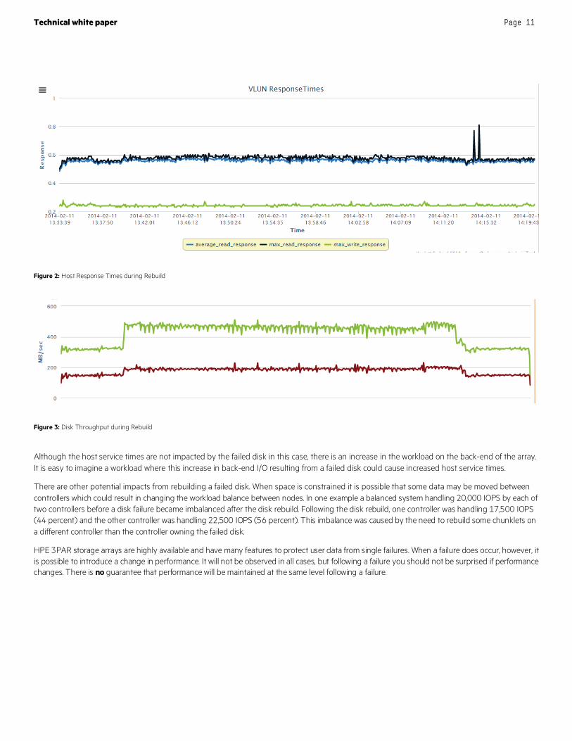
Figures 2 and 3 show one example of the impact of a failed disk on performance. Figure 2 shows the host service times, which in this example remain constant. In this case, the read service times (blue lines on top) and write service times (green line on the bottom) seen by the host do not change. The host is unaware of the disk failure.
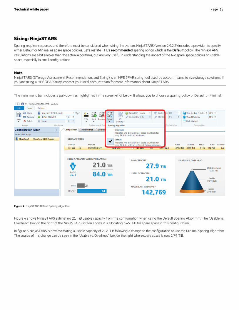
Figure 3 shows what’s happening on the back-end of the array in the same example. You can clearly see a large increase in the read rate (green line goes from ~300 Mbps to ~500 Mbps) and a smaller increase in the write rate (red line).
Technical white paper Page 11
Figure 2: Host Response Times during Rebuild
Figure 3: Disk Throughput during Rebuild
Although the host service times are not impacted by the failed disk in this case, there is an increase in the workload on the back-end of the array. It is easy to imagine a workload where this increase in back-end I/O resulting from a failed disk could cause increased host service times.
There are other potential impacts from rebuilding a failed disk. When space is constrained it is possible that some data may be moved between controllers which could result in changing the workload balance between nodes. In one example a balanced system handling 20,000 IOPS by each of two controllers before a disk failure became imbalanced after the disk rebuild. Following the disk rebuild, one controller was handling 17,500 IOPS (44 percent) and the other controller was handling 22,500 IOPS (56 percent). This imbalance was caused by the need to rebuild some chunklets on a different controller than the controller owning the failed disk.
HPE 3PAR storage arrays are highly available and have many features to protect user data from single failures. When a failure does occur, however, it is possible to introduce a change in performance. It will not be observed in all cases, but following a failure you should not be surprised if performance changes. There is no guarantee that performance will be maintained at the same level following a failure.
Technical white paper Page 12
Sizing: NinjaSTARS Sparing requires resources and therefore must be considered when sizing the system. NinjaSTARS (version 2.9.2.2) includes a provision to specify either Default or Minimal as spare space policies. Let’s restate HPE’s recommended sparing option which is the Default policy. The NinjaSTARS calculations are a bit simpler than the actual algorithms, but are very useful in understanding the impact of the two spare space policies on usable space, especially in small configurations.
Note NinjaSTARS (STorage Assessment, Recommendation, and Sizing) is an HPE 3PAR sizing tool used by account teams to size storage solutions. If you are sizing a HPE 3PAR array, contact your local account team for more information about NinjaSTARS.
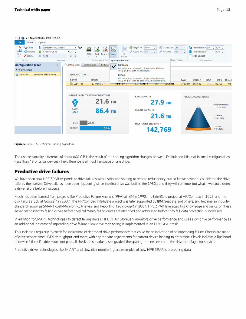
The main menu bar includes a pull-down as highlighted in the screen-shot below. It allows you to choose a sparing policy of Default or Minimal.
Figure 4: NinjaSTARS Default Sparing Algorithm
Figure 4 shows NinjaSTARS estimating 21 TiB usable capacity from the configuration when using the Default Sparing Algorithm. The “Usable vs. Overhead” box on the right of the NinjaSTARS screen shows it is allocating 3.49 TiB for spare space in this configuration.
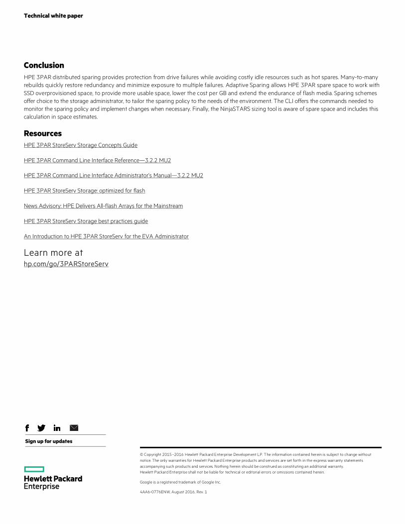
In figure 5 NinjaSTARS is now estimating a usable capacity of 21.6 TiB following a change to the configuration to use the Minimal Sparing Algorithm. The source of this change can be seen in the “Usable vs. Overhead” box on the right where spare space is now 2.79 TiB.
Technical white paper Page 13
Figure 5: NinjaSTARS Minimal Sparing Algorithm
The usable capacity difference of about 600 GiB is the result of the sparing algorithm changes between Default and Minimal. In small configurations (less than 48 physical devices), the difference is at most the space of one drive.
Predictive drive failures We have seen how HPE 3PAR responds to drive failures with distributed sparing to restore redundancy, but so far we have not considered the drive failures themselves. Drive failures have been happening since the first drive was built in the 1950s, and they will continue, but what if we could detect a drive failure before it occurs?
Much has been learned from projects like Predictive Failure Analysis (PFA) at IBM in 1992, the IntelliSafe project at HP/Compaq in 1995, and the disk failure study at GoogleTM in 2007. The HP/Compaq IntelliSafe project was later supported by IBM, Seagate, and others, and became an industry standard known as SMART (Self-Monitoring, Analysis and Reporting Technology) in 2004. HPE 3PAR leverages this knowledge and builds on these advances to identify failing drives before they fail. When failing drives are identified and addressed before they fail, data protection is increased.
In addition to SMART technologies to detect failing drives, HPE 3PAR StoreServ monitors drive performance and uses slow drive performance as an additional indicator of impending drive failure. Slow drive monitoring is implemented in an HPE 3PAR task.
This task runs regularly to check for indications of degraded drive performance that could be an indication of an impending failure. Checks are made of drive service times, IOPS, throughput, and more, with appropriate adjustments for current device loading to determine if levels indicate a likelihood of device failure. If a drive does not pass all checks, it is marked as degraded; the sparing routines evacuate the drive and flag it for service.
Predictive drive technologies like SMART and slow disk monitoring are examples of how HPE 3PAR is protecting data.
Technical white paper
Sign up for updates
© Copyright 2015–2016 Hewlett Packard Enterprise Development LP. The information contained herein is subject to change without notice. The only warranties for Hewlett Packard Enterprise products and services are set forth in the express warranty statements accompanying such products and services. Nothing herein should be construed as constituting an additional warranty. Hewlett Packard Enterprise shall not be liable for technical or editorial errors or omissions contained herein.
Google is a registered trademark of Google Inc.
4AA6-0776ENW, August 2016, Rev. 1
Conclusion HPE 3PAR distributed sparing provides protection from drive failures while avoiding costly idle resources such as hot spares. Many-to-many rebuilds quickly restore redundancy and minimize exposure to multiple failures. Adaptive Sparing allows HPE 3PAR spare space to work with SSD overprovisioned space, to provide more usable space, lower the cost per GB and extend the endurance of flash media. Sparing schemes offer choice to the storage administrator, to tailor the sparing policy to the needs of the environment. The CLI offers the commands needed to monitor the sparing policy and implement changes when necessary. Finally, the NinjaSTARS sizing tool is aware of spare space and includes this calculation in space estimates.
Resources HPE 3PAR StoreServ Storage Concepts Guide
HPE 3PAR Command Line Interface Reference—3.2.2 MU2
HPE 3PAR Command Line Interface Administrator’s Manual—3.2.2 MU2
HPE 3PAR StoreServ Storage: optimized for flash
News Advisory: HPE Delivers All-flash Arrays for the Mainstream
HPE 3PAR StoreServ Storage best practices guide
An Introduction to HPE 3PAR StoreServ for the EVA Administrator
Learn more at hp.com/go/3PARStoreServ