Embed Size (px)
Citation preview

HP XP P9000 Provisioning for Open SystemsUser Guide
AbstractThis guide describes and provides instructions for using HP XP P9000 provisioning software to configure and perform itsoperations on HP P9500 disk arrays. Provisioning software includes Thin Provisioning, Smart Tiers, Open Volume Management(Virtual LUN and LUSE), LUN Manager, and Data Retention. The intended audience is a storage system administrator orauthorized service provider with independent knowledge of HP XP P9000 disk arrays and the HP Remote Web Console.
HP Part Number: AV400-96631Published: March 2014Edition: Eleventh
© Copyright 2010, 2014 Hewlett-Packard Development Company, L.P.
Confidential computer software. Valid license from HP required for possession, use or copying. Consistent with FAR 12.211 and 12.212, CommercialComputer Software, Computer Software Documentation, and Technical Data for Commercial Items are licensed to the U.S. Government undervendor's standard commercial license.
The information contained herein is subject to change without notice. The only warranties for HP products and services are set forth in the expresswarranty statements accompanying such products and services. Nothing herein should be construed as constituting an additional warranty. HP shallnot be liable for technical or editorial errors or omissions contained herein.
Acknowledgements
Microsoft®, Windows®, Windows® XP, and Windows NT® are U.S. registered trademarks of Microsoft Corporation.
UNIX® is a registered trademark of The Open Group.
Export Requirements
You may not export or re-export this document or any copy or adaptation in violation of export laws or regulations.
Without limiting the foregoing, this document may not be exported, re-exported, transferred or downloaded to or within (or to a national residentof) countries under U.S. economic embargo, including Cuba, Iran, North Korea, Sudan, and Syria. This list is subject to change.
This document may not be exported, re-exported, transferred, or downloaded to persons or entities listed on the U.S. Department of CommerceDenied Persons List, Entity List of proliferation concern or on any U.S. Treasury Department Designated Nationals exclusion list, or to parties directlyor indirectly involved in the development or production of nuclear, chemical, biological weapons, or in missile technology programs as specifiedin the U.S. Export Administration Regulations (15 CFR 744).
Revision History
DescriptionDateEdition
Applies to microcode version 70-01-01-00/00 or later.October 2010First
Applies to microcode version 70-01-24-00/00 or later.November 2010Second
Applies to microcode version 70-01-62-00/00 or later.January 2011Third
Applies to microcode version 70-02-01-00/00 or later.May 2011Fourth
Applies to microcode version 70-02-5x-00/00 or later.September 2011Fifth
Applies to microcode version 70-03-0x-00/00 or later.November 2011Sixth
Applies to microcode version 70-03-0x-00/00 or later.April 2012Seventh
Applies to microcode version 70-03-0x-00/00 or later.July 2012Eighth
Applies to microcode version 70-03-0x-00/00 or later.November 2012Ninth
Applies to microcode version 70-06-00-00/00 or later.July 2013Tenth
Applies to microcode version 70-06-15-00/00 or later.March 2014Eleventh

Contents1 Introduction to provisioning........................................................................14
About provisioning.................................................................................................................14Basic provisioning..................................................................................................................14Fixed-sized provisioning...........................................................................................................14Disadvantages ......................................................................................................................15When to use fixed-sized provisioning.........................................................................................16Custom-sized provisioning........................................................................................................16Expanded LU provisioning.......................................................................................................16When to use custom-sized provisioning......................................................................................17When to use expanded-LU provisioning.....................................................................................17Basic provisioning workflow.....................................................................................................17Thin Provisioning Overview......................................................................................................18Thin Provisioning....................................................................................................................18Thin Provisioning concepts ......................................................................................................18When to use Thin Provisioning..................................................................................................19Thin Provisioning advantages...................................................................................................19Thin Provisioning advantage example........................................................................................20Thin Provisioning work flow......................................................................................................20Smart Tiers............................................................................................................................20Tiers concept..........................................................................................................................21When to use Smart Tiers..........................................................................................................21Data retention strategies..........................................................................................................22Resource groups strategies.......................................................................................................22Complimentary strategies........................................................................................................22Key terms..............................................................................................................................22Before you begin....................................................................................................................23About cache management devices............................................................................................24
Calculating the number of cache management devices required by a THP V-VOL.......................24Maximum capacity of cache management device..............................................................24
Calculating the number of cache management devices required by a volume that is not a THPV-VOL...............................................................................................................................25Viewing the number of cache management devices................................................................25
2 Configuring resource groups......................................................................26System configuration using resource groups................................................................................26Resource groups examples.......................................................................................................26
Example of resource groups sharing a port............................................................................26Example of resource groups not sharing ports........................................................................28
Meta_resource.......................................................................................................................29Resource lock.........................................................................................................................29User groups...........................................................................................................................29Resource group assignments.....................................................................................................29Resource group license requirements.........................................................................................30Resource group rules, restrictions, and guidelines........................................................................30Creating a resource group.......................................................................................................30Adding resources to a resource group.......................................................................................31Removing resources from a resource group.................................................................................32Managing Resource Groups.....................................................................................................32
Changing the name of a resource group...............................................................................32Deleting a resource group...................................................................................................33
Using Resource Partition and other P9500 products.....................................................................33Snapshot..........................................................................................................................34
Contents 3
Thin Provisioning................................................................................................................34DKA Encryption.................................................................................................................35External Storage Access Manager........................................................................................35LUN Expansion..................................................................................................................35LUN Manager...................................................................................................................36Performance Monitor..........................................................................................................37Business Copy...................................................................................................................37Fast Snap.........................................................................................................................37Continuous Access Synchronous...........................................................................................38Continuous Access Journal..................................................................................................39External Storage................................................................................................................40Open Volume Management................................................................................................41Cache Partition..................................................................................................................41Auto LUN..........................................................................................................................41Volume Shredder...............................................................................................................42Configuration File Loader....................................................................................................42CLI Spreadsheet for LUN Expansion.....................................................................................42Performance Control...........................................................................................................43
3 Configuring custom-sized provisioning.........................................................44Virtual LVI/Virtual LUN functions...............................................................................................44VLL requirements.....................................................................................................................44VLL specifications....................................................................................................................44
Virtual LUN specifications for open systems...........................................................................44CV capacity by emulation type for open systems....................................................................45
SSID requirements ..................................................................................................................45VLL size calculations................................................................................................................45
Calculating OPEN-V volume size (CV capacity unit is MB).......................................................46Calculating OPEN-V volume size (CV capacity unit is blocks)...................................................46Calculating fixed-size open-systems volume size (CV capacity unit is MB)..................................47Calculating fixed-size open-systems volume size (CV capacity unit is blocks)..............................47Calculating the size of a CV using Enhanced mode on SATA drives..........................................48
Management area capacity of an open-systems volume.....................................................49Boundary values for RAID levels (Enhanced mode on SATA drives)......................................50Boundary values for RAID levels (other than Enhanced mode on SATA drives).......................50Capacity of a slot..........................................................................................................50Calculated management area capacities (SATA-E drive).....................................................50
Configuring volumes in a parity group .................................................................................51Create LDEV function..............................................................................................................51
Creating an LDEV..............................................................................................................51Finding an LDEV ID............................................................................................................54Finding an LDEV SSID ........................................................................................................54Editing an LDEV SSID ........................................................................................................54Changing LDEV settings......................................................................................................55Removing an LDEV to be registered......................................................................................55
Blocking an LDEV...................................................................................................................55Restoring a blocked LDEV........................................................................................................56Editing an LDEV name.............................................................................................................56Deleting an LDEV (converting to free space)...............................................................................57Formatting LDEVs....................................................................................................................57
About formatting LDEVs......................................................................................................58Storage system operation when LDEVs are formatted..............................................................58Quick Format function.........................................................................................................58
Quick Format specifications............................................................................................59Formatting a specific LDEV..................................................................................................60
4 Contents

Formatting all LDEVs in a parity group..................................................................................60Assigning a processor blade ...................................................................................................61
Assigning a processor blade to a resource............................................................................61Changing the processor blade assigned to an LDEV...............................................................61
Using a system disk................................................................................................................62System disk rules, restrictions, and guidelines.........................................................................63
4 Configuring expanded LU provisioning........................................................64About LUSE ...........................................................................................................................64LUN Expansion license requirements.........................................................................................64LUSE configuration example.....................................................................................................64LUSE configuration rules, restrictions, and guidelines...................................................................65LUSE operations using a path-defined LDEV................................................................................66LUSE provisioning workflow......................................................................................................67Opening the LUN Expansion window........................................................................................67Viewing a concatenated parity group........................................................................................68Creating a LUSE volume .........................................................................................................68Resetting an unregistered LUSE volume......................................................................................71Maintaining LUSE volumes.......................................................................................................71
Viewing LUSE volume details...............................................................................................71Changing capacity on a LUSE volume..................................................................................72Releasing a LUSE volume....................................................................................................72
5 Configuring thin provisioning ....................................................................74Thin Provisioning overview.......................................................................................................74Smart Tiers overview...............................................................................................................74Thin provisioning requirements.................................................................................................74
License requirements...........................................................................................................74Pool requirements...............................................................................................................75Pool-VOL requirements........................................................................................................76THP V-VOL requirements......................................................................................................77Requirements for increasing THP V-VOL capacity....................................................................78Operating system and file system capacity............................................................................79
Using Thin Provisioning or Smart Tiers with other P9500 products.................................................80Interoperability of THP V-VOLs and pool-VOLs........................................................................80Business Copy pair status for reclaiming zero pages...............................................................83Continuous Access Synchronous...........................................................................................83Continuous Access Journal..................................................................................................84Business Copy...................................................................................................................84Snapshot..........................................................................................................................85Fast Snap.........................................................................................................................85Cache Partition CLPR setting................................................................................................85Auto LUN..........................................................................................................................85Resource Partition...............................................................................................................85
Thin Provisioning workflow.......................................................................................................86Smart Tiers............................................................................................................................87
About tiered storage...........................................................................................................87Tier monitoring and data relocation......................................................................................87Smart Pool........................................................................................................................87Tier monitoring and relocation cycles....................................................................................87Tier relocation flow............................................................................................................94Tier relocation rules, restrictions, and guidelines.....................................................................96Buffer area of a tier............................................................................................................99
Setting external volumes for each tier...............................................................................99Smart Tiers cache specifications and requirements................................................................101Execution modes for tier relocation.....................................................................................101
Contents 5
Execution modes when using Remote Web Console.........................................................101Execution modes when using RAID Manager..................................................................103
Monitoring modes............................................................................................................105Cautions when using monitoring modes.........................................................................106
Notes on performing monitoring........................................................................................106Downloading the tier relocation log file..............................................................................106
Tier relocation log file contents......................................................................................107Tiering policy..................................................................................................................107
Tiering policy expansion..............................................................................................108Tiering policy examples................................................................................................108Setting tiering policy on a THP V-VOL............................................................................109Tiering policy levels.....................................................................................................110Viewing the tiering policy in the performance graph........................................................110Reserving tier capacity when setting a tiering policy........................................................112Example of reserving tier capacity.................................................................................112Notes on tiering policy settings.....................................................................................114New page assignment tier...........................................................................................115Relocation priority.......................................................................................................116Assignment tier when pool-VOLs are deleted...................................................................117Formatted pool capacity..............................................................................................118Rebalancing the usage level among pool-VOLs...............................................................118Execution mode settings and tiering policy......................................................................119Changing the tiering policy level on a THP V-VOL............................................................120
Changing new page assignment tier of a V-VOL..................................................................121Opening the Edit Tiering Policies window............................................................................121Changing a tiering policy.................................................................................................121
To change the tiering policy..........................................................................................121Changing relocation priority setting of a V-VOL....................................................................122Smart Tiers workflow........................................................................................................123Smart Tiers tasks and parameters.......................................................................................125
Task and parameter settings.........................................................................................125Display items: Setting parameters..................................................................................126Display items: Capacity usage for each tier....................................................................127Display items: Performance monitor statistics...................................................................127Display items: Operation status of performance monitor/relocation....................................127
Managing Smart Tiers......................................................................................................127Changing pool for Thin Provisioning to pool for Smart Tiers..............................................127Changing monitoring and tier relocation settings.............................................................129Changing monitoring mode setting................................................................................130Changing buffer space for new page assignment setting..................................................130Changing buffer space for tier relocation setting.............................................................131
Viewing pool tier information.............................................................................................131Viewing THP V-VOL tier information....................................................................................131
Changing a pool for Smart Tiers to a pool for Thin Provisioning..................................................131Working with pools..............................................................................................................132
About pools....................................................................................................................132About pool-VOLs..............................................................................................................132Pool status.......................................................................................................................133Creating a pool...............................................................................................................133
Notes on pools created with the previous versions.....................................................................138Pool-VOLs of RAID 5 and RAID 6 coexisting in the Thin Provisioning pool................................138Pool-VOLs to which external volumes are mapped assigned to the Smart Tiers pool...................139Pool-VOLs of RAID 1 assigned to the Smart Tiers pool...........................................................139Pool-VOLs of RAID 1 and RAID 5, or pool-VOLs of RAID 1 and RAID 6 coexisting in the samepool...............................................................................................................................139
6 Contents

Working with THP V-VOLs......................................................................................................139About THP V-VOLs...........................................................................................................139Relationship between a pool and THP V-VOLs......................................................................140Creating V-VOLs..............................................................................................................140Editing a THP V-VOL's SSID...............................................................................................142Changing THP V-VOL settings............................................................................................143Removing the THP V-VOL to be registered............................................................................143Formatting LDEVs in a Windows environment......................................................................143
Monitoring capacity and performance....................................................................................143Monitoring pool capacity..................................................................................................143Monitoring pool usage levels.............................................................................................144Monitoring performance...................................................................................................144
Managing I/O usage rates example.............................................................................145Tuning with Smart Tiers.....................................................................................................145
Thresholds...........................................................................................................................146Pool utilization thresholds..................................................................................................146Pool subscription limit.......................................................................................................146Changing pool thresholds.................................................................................................147Changing the pool subscription limit...................................................................................148
Working with SIMs...............................................................................................................148About SIMs.....................................................................................................................148SIM reference codes.........................................................................................................148Automatic completion of a SIM .........................................................................................149Manually completing a SIM..............................................................................................149
Managing pools and THP V-VOLs...........................................................................................150Viewing pool information..................................................................................................150Viewing formatted pool capacity........................................................................................151Viewing the progress of rebalancing the usage level among pool-VOLs ..................................152Increasing pool capacity...................................................................................................152Changing a pool name....................................................................................................153Recovering a blocked pool................................................................................................154Decrease pool capacity....................................................................................................154
About decreasing pool capacity....................................................................................154Decreasing pool capacity.............................................................................................156Stopping the decrease of pool capacity.........................................................................156
Deleting a tier in a pool....................................................................................................156Deleting a pool...............................................................................................................157Changing external LDEV tier rank......................................................................................158Increasing THP V-VOL capacity..........................................................................................158Changing the name of a THP V-VOL...................................................................................159About releasing pages in a THP V-VOL...............................................................................159
Releasing pages in a THP V-VOL...................................................................................160Stopping the release of pages in a THP V-VOL................................................................161
Enabling/disabling tier relocation of a THP V-VOL...............................................................162Deleting a THP V-VOL.......................................................................................................162
6 Configuring access attributes...................................................................164About access attributes..........................................................................................................164Access attribute requirements.................................................................................................164Access attributes and permitted operations...............................................................................165Access attribute restrictions.....................................................................................................165Access attributes work flow....................................................................................................165Assigning an access attribute to a volume................................................................................166Changing an access attribute to read-only or protect.................................................................166Changing an access attribute to read/write.............................................................................168
Contents 7

Enabling or disabling the expiration lock.................................................................................168Disabling an S-VOL...............................................................................................................169Reserving volumes................................................................................................................169
7 Managing logical volumes......................................................................171LUN Manager overview........................................................................................................171
LUN Manager operations.................................................................................................171Fibre channel operations...................................................................................................171LUN Manager license requirements....................................................................................172LUN Manager rules, restrictions, and guidelines...................................................................172
Managing logical units workflow............................................................................................173Configuring hosts and fibre channel ports................................................................................173Configuring fibre channel ports..............................................................................................174
Setting the data transfer speed on a fibre channel port.........................................................174Setting the fibre channel port address.................................................................................174Addresses for fibre channel ports.......................................................................................175Setting the fabric switch....................................................................................................176Fibre channel topology.....................................................................................................176
Example of FC-AL and point-to-point topology.................................................................177Configuring hosts..................................................................................................................177
Configure hosts workflow..................................................................................................177Host modes for host groups...............................................................................................177Host mode options...........................................................................................................179
Find WWN of the host bus adapter..............................................................................181Finding a WWN on Windows......................................................................................181Finding a WWN on Oracle® Solaris............................................................................182Finding a WWN on AIX, IRIX, or Sequent......................................................................182Finding WWN for HP-UX.............................................................................................182
Creating a host group and registering hosts in the host group (in a Fibre Channel environment)...183Configuring LU paths.............................................................................................................185
Defining LU paths.............................................................................................................185Setting a UUID................................................................................................................186Correspondence table for defining devices..........................................................................187Defining alternate LU paths...............................................................................................187Managing LU paths..........................................................................................................188
Deleting LU paths........................................................................................................188Clearing a UUID setting...............................................................................................189Viewing LU path settings..............................................................................................189
Releasing LUN reservation by host..........................................................................................190LUN security on ports............................................................................................................190
Examples of enabling and disabling LUN security on ports....................................................190Enabling LUN security on a port........................................................................................192Disabling LUN security on a port.......................................................................................192
Setting fibre channel authentication.........................................................................................192User authentication..........................................................................................................193
Settings for authentication of hosts.................................................................................193Settings for authentication of ports (required if performing mutual authentication).................194
Host and host group authentication....................................................................................194Example of authenticating hosts in a fibre channel environment.........................................195Port settings and connection results................................................................................197
Fabric switch authentication...............................................................................................197Fabric switch settings and connection results........................................................................199Mutual authentication of ports...........................................................................................199Fibre channel authentication..............................................................................................199
Enabling or disabling host authentication on a host group................................................199
8 Contents

Registering host user information...................................................................................200Changing host user information registered on a host group...............................................201Deleting host user information.......................................................................................201Registering user information for a host group (for mutual authentication).............................202Clearing user information from a host group...................................................................202
Fibre channel port authentication.......................................................................................203Setting fibre channel port authentication.........................................................................203
Registering user information on a fibre channel port.............................................................203Registering user information on a fabric switch.....................................................................204Clearing fabric switch user information...............................................................................204Setting the fabric switch authentication mode.......................................................................205Enabling or disabling fabric switch authentication................................................................205
Managing hosts...................................................................................................................205Changing WWN or nickname of a host bus adapter...........................................................205Changing the name or host mode of a host group................................................................206Initializing host group 0....................................................................................................207Deleting a host bus adapter from a host group.....................................................................207Deleting old WWNs from the WWN table.........................................................................207Deleting a host group.......................................................................................................208
8 Troubleshooting......................................................................................209Troubleshooting VLL..............................................................................................................209Troubleshooting Thin Provisioning...........................................................................................209Troubleshooting Data Retention...............................................................................................213
Data Retention troubleshooting instructions..........................................................................214Troubleshooting provisioning while using RAID Manager...........................................................214
Errors when operating RAID Manager (Thin Provisioning, SSB1: 0x2e31/0xb96d) ..................214Errors when operating RAID Manager (Data Retention, SSB1:2E31/B9BF/B9BD).....................215
Calling HP Technical Support.................................................................................................2169 Support and other resources....................................................................217
Contacting HP......................................................................................................................217Subscription service..........................................................................................................217Documentation feedback..................................................................................................217
Related information...............................................................................................................217HP websites....................................................................................................................217
Conventions for storage capacity values..................................................................................218Typographic conventions.......................................................................................................218
A RAID Manager command reference..........................................................220Remote Web Console tasks and RAID Manager command list....................................................220
B Resource Partition GUI reference...............................................................222Resource Groups window......................................................................................................222
Summary and buttons.......................................................................................................222Resource Groups tab........................................................................................................223
Window after selecting a resource group.................................................................................223Parity Groups tab.............................................................................................................224LDEVs tab.......................................................................................................................225Ports tab.........................................................................................................................227Host Groups tab..............................................................................................................228
Create Resource Groups wizard..............................................................................................228Create Resource Groups window.......................................................................................228Select Parity Groups window.............................................................................................231Select LDEVs window.......................................................................................................232Select Ports window.........................................................................................................235Select Host Groups window..............................................................................................236
Contents 9

Create Resource Groups Confirm window...........................................................................237Edit Resource Group wizard...................................................................................................238
Edit Resource Group window.............................................................................................238Edit Resource Group Confirm window.................................................................................239
Add Resources wizard...........................................................................................................240Add Resources window....................................................................................................240Add Resources Confirm window.........................................................................................240
Remove Resources window....................................................................................................243Delete Resource Groups window............................................................................................245Resource Group Properties window.........................................................................................246
C LDEV GUI reference................................................................................249Parity Groups window...........................................................................................................249Parity Groups window after selecting Internal (or External) under Parity Groups.............................251Window after selecting a parity group under Internal (or External) of Parity Groups.......................253Window after selecting Logical Devices...................................................................................255Create LDEVs wizard.............................................................................................................258
Create LDEVs window......................................................................................................258Create LDEVs Confirm window..........................................................................................264
Edit LDEVs wizard.................................................................................................................265Edit LDEVs window..........................................................................................................266Edit LDEVs Confirm window..............................................................................................267
Change LDEV Settings window...............................................................................................268View SSIDs window..............................................................................................................269Select Free Spaces window....................................................................................................269Select Pool window...............................................................................................................271View LDEV IDs window.........................................................................................................271
Emulation groups and types..............................................................................................272View Physical Location window..............................................................................................273Edit SSIDs window................................................................................................................274Change SSIDs window..........................................................................................................274Format LDEVs wizard............................................................................................................275
Format LDEVs window......................................................................................................275Format LDEVs Confirm window..........................................................................................275
Restore LDEVs window..........................................................................................................276Block LDEVs window.............................................................................................................277Delete LDEVs window............................................................................................................278LDEV Properties window........................................................................................................279Top window when selecting Components.................................................................................284Top window when selecting controller chassis under Components...............................................285Edit Processor Blades wizard..................................................................................................287
Edit Processor Blades window............................................................................................287Edit Processor Blades Confirm window................................................................................287
Assign Processor Blade wizard...............................................................................................288Assign Processor Blade window.........................................................................................288Assign Processor Blade Confirm window.............................................................................288
View Management Resource Usage window............................................................................290D LUSE GUI reference................................................................................291
LUN Expansion window .......................................................................................................291LDEV Information tree.......................................................................................................291LDEV Detail table.............................................................................................................291
LDEV operation detail...........................................................................................................293RAID Concatenation dialog box.............................................................................................294Set LUSE confirmation dialog box...........................................................................................295Reset LUSE confirmation dialog box........................................................................................296
10 Contents
Release LUSE confirmation dialog box.....................................................................................297LUSE Detail dialog box..........................................................................................................298
E Thin Provisioning and Smart Tiers GUI reference.........................................299Pools window after selecting pool (Pools window).....................................................................299Top window when selecting a pool under Pools........................................................................304Create Pools wizard..............................................................................................................312
Create Pools window........................................................................................................312Create Pools Confirm window............................................................................................318
Expand Pool wizard..............................................................................................................320Expand Pool window........................................................................................................320Expand Pool Confirm window............................................................................................321
Edit Pools wizard..................................................................................................................322Edit Pools window............................................................................................................322Edit Pools Confirm window................................................................................................324
Delete Pools wizard...............................................................................................................327Delete Pools window........................................................................................................327Delete Pools Confirm window............................................................................................328
Expand V-VOLs wizard..........................................................................................................329Expand V-VOLs window....................................................................................................329Expand V-VOLs Confirm window........................................................................................330
Restore Pools window............................................................................................................332Shrink Pool window..............................................................................................................333Stop Shrinking Pools window.................................................................................................334Complete SIMs window.........................................................................................................335Select Pool VOLs window.......................................................................................................335Reclaim Zero Pages window...................................................................................................338Stop Reclaiming Zero Pages window.......................................................................................339Pool Property window...........................................................................................................339View Tier Properties window..................................................................................................341Monitor Pools window...........................................................................................................346Stop Monitoring Pools window...............................................................................................347Start Tier Relocation window..................................................................................................348Stop Tier Relocation window..................................................................................................349View Pool Management Status window....................................................................................350Edit External LDEV Tier Rank wizard........................................................................................354
Edit External LDEV Tier Rank window..................................................................................354Edit External LDEV Tier Rank Confirm window......................................................................355
Edit Tiering Policies wizard.....................................................................................................356Edit Tiering Policies window...............................................................................................356Edit Tiering Policies Confirm window...................................................................................357
Change Tiering Policy Window..............................................................................................358F Data Retention GUI reference...................................................................360
Data Retention window.........................................................................................................360Error Detail Dialog Box.........................................................................................................362
G LUN Manager GUI reference ..................................................................363Port/Host Groups window after selecting Ports/Host Groups......................................................363Port/Host Groups window after selecting a port under Ports/Host Groups....................................367Port/Hosts window when selecting a host group under the port of Ports/Host Groups....................370Add LUN Paths wizard..........................................................................................................373
Select LDEVs window.......................................................................................................373Select Host Groups window..............................................................................................376Add LUN Paths window....................................................................................................379Add LUN Paths Confirm window........................................................................................380
Contents 11

Create Host Groups wizard....................................................................................................381Create Host Groups window.............................................................................................381Create Host Groups Confirm window.................................................................................385
Edit Host Groups wizard........................................................................................................385Edit Host Groups window..................................................................................................385Edit Host Groups Confirm window......................................................................................387
Add to Host Groups wizard (when specific host is selected)........................................................388Add to Host Groups window.............................................................................................388Add to Host Groups Confirm window.................................................................................391
Add Hosts wizard (when specific hosts group is selected)...........................................................392Add Hosts window...........................................................................................................392Add Hosts Confirm window...............................................................................................394
Delete LUN Paths wizard........................................................................................................396Delete LUN Paths window.................................................................................................396Delete LUN Paths Confirm window.....................................................................................397
Edit Host wizard...................................................................................................................397Edit Host window.............................................................................................................398Edit Host Confirm window.................................................................................................398
Edit Ports wizard...................................................................................................................399Edit Ports window............................................................................................................400Edit Ports Confirm window.................................................................................................401
Create Alternative LUN Paths wizard.......................................................................................402Create Alternative LUN Paths window.................................................................................402Create Alternative LUN Paths Confirm window.....................................................................404
Copy LUN Paths wizard.........................................................................................................406Copy LUN Paths window..................................................................................................406Copy LUN Paths Confirm window......................................................................................408
Remove Hosts wizard............................................................................................................410Remove Hosts window......................................................................................................410Remove Hosts Confirm window..........................................................................................410
Edit UUIDs wizard................................................................................................................412Edit UUIDs window..........................................................................................................412Edit UUIDs Confirm window..............................................................................................412
Add New Host window.........................................................................................................414Change LUN IDs window......................................................................................................414Delete Host Groups window...................................................................................................415Delete Login WWNs window.................................................................................................416Delete UUIDs window...........................................................................................................417Host Group Properties window...............................................................................................417LUN Properties window.........................................................................................................419Authentication window..........................................................................................................421
Authentication window (fibre folder selected).......................................................................421Port tree.....................................................................................................................421Port information list......................................................................................................422Fabric Switch information list.........................................................................................422
Authentication window (fibre port selected).........................................................................422Port tree.....................................................................................................................423Authentication information (target) list............................................................................424Authentication information (host) list...............................................................................424
Add New User Information (Host) window..........................................................................424Change User Information (Host) window.............................................................................425Clear Authentication information window............................................................................425Specify Authentication Information window.........................................................................426
Edit Command Devices wizard...............................................................................................426Edit Command Devices window.........................................................................................427
12 Contents

Edit Command Devices Confirm window.............................................................................428Host-Reserved LUNs window..................................................................................................430Release Host-Reserved LUNs wizard........................................................................................431
Release Host-Reserved LUNs window..................................................................................431View Login WWN Status window...........................................................................................432
Glossary..................................................................................................433Index.......................................................................................................435
Contents 13

1 Introduction to provisioningProvisioning a storage system requires balancing the costs of the solution with the benefits that thesolution provides. The following is an overview of provisioning strategies that you can implementon the P9500 to support your business.
About provisioningProvisioning is a method of managing storage system devices or volumes. Some provisioningmethods are host-based, while others use existing storage system capabilities such as logical unitsize expansion (LUSE) or concatenated array groups. Some provisioning methods arehardware-based, and others are software-based. Each technique has its particular use and benefit,for example, capacity, reliability, performance, or cost considerations, in a given storageenvironment. Used in the wrong scenario, each can be expensive, awkward, time consuming toconfigure and maintain, and can be potentially error prone. Your support representatives areavailable to help you configure the highest quality solution for your storage environment.Provisioning strategies falls into two fundamental categories:
• “Basic provisioning” (page 14) (or traditional provisioning). Basic provisioning includes logicaldevices (LDEVs), custom-sized volumes, and expanded-LU volumes.
• “Thin Provisioning Overview” (page 18) (or virtual provisioning). Thin provisioning includespooling physical storage and creating logical devices for hosts.
Basic provisioningSeveral basic provisioning techniques traditionally are used to manage storage volumes. Thesestrategies are useful in specific scenarios based on user needs, such as whether you use open ormainframe storage systems, or you prefer manual or automated control of your storage resources.Basic provisioning relies on carving up physical storage into smaller units. Custom sizing is possible,and requires using Virtual LUN software. If a larger capacity logical unit is required, expandingthe size of a logical volume is possible and requires the use of LUN Expansion software.Basic provisioning includes:
• “Fixed-sized provisioning” (page 14)
• “Custom-sized provisioning” (page 16)
• “Expanded LU provisioning” (page 16)
Fixed-sized provisioningTwo traditional fixed-size host-based volume management methods typically are used on opensystems to organize storage space on a server. One method is the direct use of physical volumesas devices for use either as raw space or as a local or clustered file system. These are fixed-sizevolumes with a fixed number of disks, and as such, each has a certain inherent physical randominput/output operation per second (IOPS) or sequential throughput (megabytes per second) capacity.A System Administrator manages the aggregate server workloads against them. As workloadsexceed the volume’s available space or its IOPS capacity, the user contents are manually movedonto a larger or faster (more spindles) volume, if possible.The following figure illustrates a simple fixed-size provisioning environment using individual LUvolumes on a host:
14 Introduction to provisioning

The alternative is to use a host-based Logical Volume Manager (LVM) when the planned workloadsrequire either more space or IOPS capacity than the individual physical volumes can provide. LVMis the disk management feature available on UNIX-based operating systems, including Linux, thatmanages their logical volumes.The following illustrates a fixed-size provisioning environment using LUNs in host-managed logicalvolumes:
In either case, hosts recognize the size as fixed regardless of the actual used size. Therefore, it isnot necessary to expand the volume (LDEV) size in the future if the actual used size does not exceedthe fixed size.When such a logical volume runs out of space or IOPS capacity, you can replace it with one thatwas created with even more physical volumes and then copy over all of the user data. In somecases, it is best to add a second logical volume and then manually relocate just part of the existingdata to redistribute the workload across two such volumes. These two logical volumes would bemapped to the server using separate host paths.
DisadvantagesSome disadvantages to using fixed-sized provisioning are:
• If you use only part of the entire capacity specified by an emulation type, the rest of thecapacity is wasted.
• After creating fixed-sized volumes, typically some physical capacity will be wasted due tobeing less than the fixed-size capacity.
• In a fixed-sized environment, manual intervention can become a costly and tedious exercisewhen a larger volume size is required.
Disadvantages 15
When to use fixed-sized provisioningFixed-sized provisioning is a best fit in the following scenarios:
• When custom-sized provisioning is not supported.
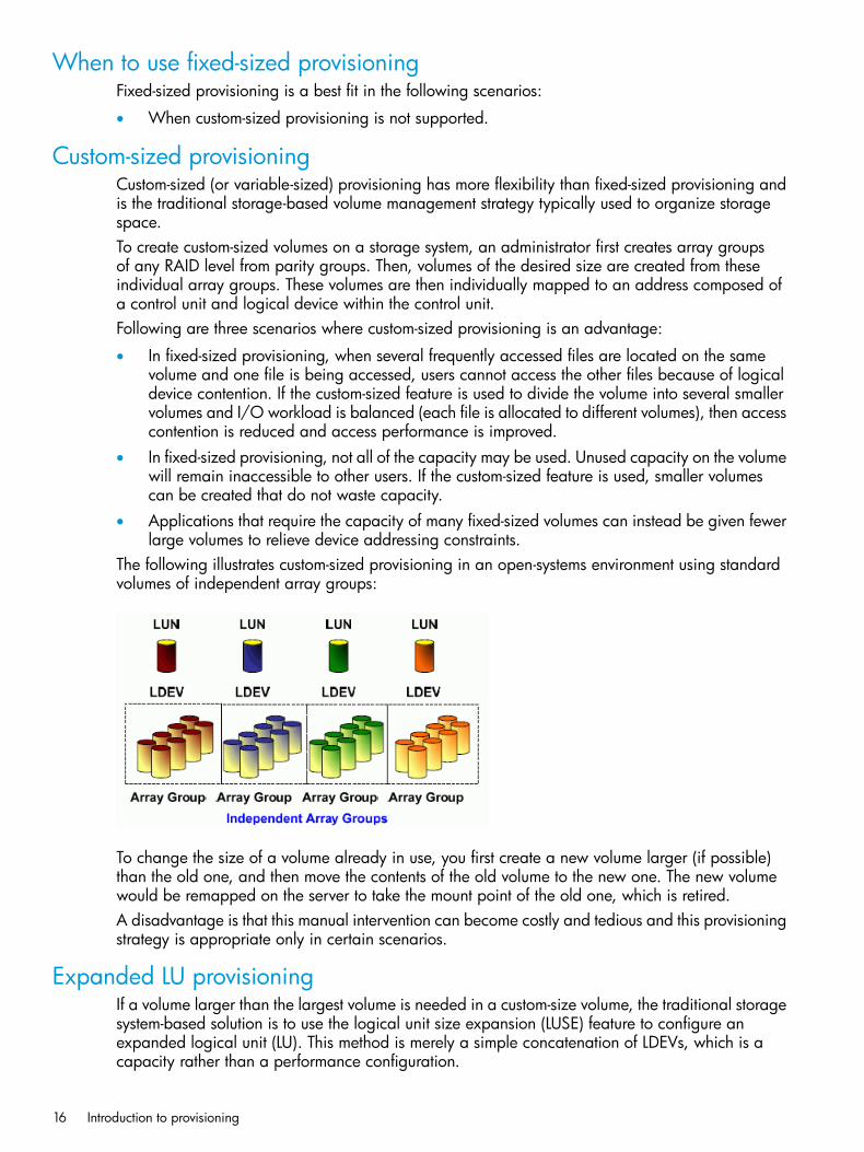
Custom-sized provisioningCustom-sized (or variable-sized) provisioning has more flexibility than fixed-sized provisioning andis the traditional storage-based volume management strategy typically used to organize storagespace.To create custom-sized volumes on a storage system, an administrator first creates array groupsof any RAID level from parity groups. Then, volumes of the desired size are created from theseindividual array groups. These volumes are then individually mapped to an address composed ofa control unit and logical device within the control unit.Following are three scenarios where custom-sized provisioning is an advantage:
• In fixed-sized provisioning, when several frequently accessed files are located on the samevolume and one file is being accessed, users cannot access the other files because of logicaldevice contention. If the custom-sized feature is used to divide the volume into several smallervolumes and I/O workload is balanced (each file is allocated to different volumes), then accesscontention is reduced and access performance is improved.
• In fixed-sized provisioning, not all of the capacity may be used. Unused capacity on the volumewill remain inaccessible to other users. If the custom-sized feature is used, smaller volumescan be created that do not waste capacity.
• Applications that require the capacity of many fixed-sized volumes can instead be given fewerlarge volumes to relieve device addressing constraints.
The following illustrates custom-sized provisioning in an open-systems environment using standardvolumes of independent array groups:
To change the size of a volume already in use, you first create a new volume larger (if possible)than the old one, and then move the contents of the old volume to the new one. The new volumewould be remapped on the server to take the mount point of the old one, which is retired.A disadvantage is that this manual intervention can become costly and tedious and this provisioningstrategy is appropriate only in certain scenarios.
Expanded LU provisioningIf a volume larger than the largest volume is needed in a custom-size volume, the traditional storagesystem-based solution is to use the logical unit size expansion (LUSE) feature to configure anexpanded logical unit (LU). This method is merely a simple concatenation of LDEVs, which is acapacity rather than a performance configuration.
16 Introduction to provisioning

The following illustrates a simple expanded LU environment, where LDEVs are concatenated toform a LUSE volume.
When to use custom-sized provisioningUse custom-sized provisioning when you want to manually control and monitor your storageresources and usage scenarios.
When to use expanded-LU provisioningExpanded-LU provisioning is a best fit in the following scenarios:
• In an open systems environment.
• When you want to manually control and monitor your storage resources and usage scenarios.
• To combine open-systems volumes to create an open-systems volume (LU) larger than 2.8 TB.
• When thin provisioning is not an option.For detailed information, see “Configuring expanded LU provisioning” (page 64).
Basic provisioning workflowThe following illustrates the basic provisioning workflow:
When to use custom-sized provisioning 17

Virtual LUN software is used to configure custom-sized provisioning. For detailed information, see“Configuring custom-sized provisioning” (page 44).
Thin Provisioning OverviewThin provisioning is an approach to managing storage that maximizes physical storage capacity.Instead of reserving a fixed amount of storage for a volume, it simply assigns capacity from theavailable physical pool when data is actually written to disk.Thin provisioning includes:
• “Thin Provisioning concepts ” (page 18)
• “Smart Tiers” (page 20)
Thin ProvisioningThough basic or traditional provisioning strategies can be appropriate and useful in specificscenarios, they can be expensive to set up, awkward and time consuming to configure, difficult tomonitor, and error prone when maintaining storage.Although Thin Provisioning requires some additional steps, it is a simpler alternative to the traditionalprovisioning methods. It uses thin provisioning technology that allows you to allocate virtual storagecapacity based on anticipated future capacity needs, using virtual volumes instead of physical diskcapacity.Overall storage use rates may improve because you can potentially provide more virtual capacityto applications while using fewer physical disks. It can provide lower initial cost, greater efficiency,and storage management freedom for storage administrators. In this way, Thin Provisioning software:
• Simplifies storage management
• Provides balanced resources and more optimized performance by default without inordinatemanual intervention.
• Maximizes physical disk usage
• May reduce device address requirements over traditional provisioning by providing largervolume sizes.
Thin Provisioning conceptsThin Provisioning is a volume management feature that allows storage managers and SystemAdministrators to efficiently plan and allocate storage to users or applications. It provides a platformfor the array to dynamically manage data and physical capacity without frequent manualinvolvement.Thin Provisioning provides three important capabilities: thin provisioning of storage, enhancedvolume performance, and larger volume sizes.Thin Provisioning is more efficient than traditional provisioning strategies. It is implemented bycreating one or more Thin Provisioning pools (THP pools) of physical storage space using multipleLDEVs. Then, you can establish virtual THP volumes (THP V-VOLs) and connect them to the individualTHP pools. In this way, capacity to support data can be randomly assigned on demand within thepool.THP V-VOLs are of a user-specified logical size without any corresponding physical space. Actualphysical space (in 42-MB pool page units) is automatically assigned to a THP V-VOL from theconnected THP pool as that volume’s logical space is written to over time. A new volume does nothave any pool pages assigned to it. The pages are loaned out from its connected pool to that THPvolume until the volume is reformatted or deleted. At that point, all of that volume’s assigned pagesare returned to the pool’s free page list. This handling of logical and physical capacity is calledthin provisioning. In many cases, logical capacity will exceed physical capacity.
18 Introduction to provisioning

Thin Provisioning enhances volume performance. This is an automatic result of how THP V-VOLsmap capacity from individual THP pools. A pool is created using from one to 1024 LDEVs (poolvolumes) of physical space. Each pool volume is sectioned into 42-MB pages. Each page isconsecutively laid down on a number of RAID stripes from one pool volume. The pool’s 42-MBpool pages are assigned on demand to any of the THP V-VOLs that are connected to that pool.Other pages assigned over time to that THP V-VOL randomly originate from the next free page ofsome other pool volume in the pool.Setting up a Thin Provisioning environment requires a few extra steps. You still configure variousarray groups to a desired RAID level and create one or more volumes (LDEVs) on each of them(see “Creating an LDEV” (page 51)). Then set up a Thin Provisioning environment by creating oneor more THP pools of physical storage space that are each a collection of some of these LDEVs(THP pool volumes). This pool structure supports creation of Thin Provisioning virtual volumes (THPV-VOLs), where 42-MB pages of data are randomly assigned on demand.For detailed information, see “Configuring thin provisioning ” (page 74).
When to use Thin ProvisioningThin Provisioning is a best fit in an open-systems environment in the following scenarios:
• Where the aggregation of storage pool capacity usage across many volumes provides thebest opportunity for performance optimization.
• For stable environments and large consistently growing files or volumes.
• Where device addressing constraints are a concern.
Thin Provisioning advantages
With Thin ProvisioningWithout Thin ProvisioningAdvantages
You can logically allocate more capacity thanis physically installed. You can purchase less
You must purchase physical disk capacity forexpected future use. The unused capacity adds
Reduces initial costs
capacity, reducing initial costs and you can addcapacity later by expanding the pool.
costs for both the storage system and softwareproducts.
Some file systems take up little pool space. Formore details, see “Operating system and filesystem capacity” (page 79).
When physical capacity becomes insufficient,you can add pool capacity without serviceinterruption.
You must stop the disk array to reconfigure it.Reducesmanagement costs
In addition, with Smart Tiers you can configurepool storage consisting of multiple types of datadrives, including SSD, SAS, SATA, and externalvolumes. This eliminates unnecessary costs.
P9500 product licenses are based on usedcapacity rather than the total defined capacity.
As the expected physical disk capacity ispurchased, the unused capacity of the storage
Reducesmanagement labor
You do not need to use LUSE because you canallocate volumes of up to 60 TB regardless ofphysical disk capacity.
system also needs to be managed on thestorage system and on licensed P9500products.
and increasesavailability ofstorage volumes forreplication
Smart Tiers allows you to use storage efficientlyby automatically migrating data to the mostsuitable data drive.
Effectively combines I/O patterns of manyapplications and evenly spreads the I/O activity
Because physical disk capacity is initiallypurchased and installed to meet expected
Increases theperformance
across available physical resources, preventingfuture needs, portions of the capacity may beefficiency of the datadrive bottlenecks in parity group performance.unused. I/O loads may concentrate on just a
Configuring the volumes from multiple paritysubset of the storage which might decreaseperformance. groups improves parity group performance. This
When to use Thin Provisioning 19

With Thin ProvisioningWithout Thin ProvisioningAdvantages
also increases storage use while reducing powerand pooling requirements (total cost ofownership).
Thin Provisioning advantage exampleTo illustrate the merits of a Thin Provisioning environment, assume you have twelve LDEVs from 12RAID 1 (2D+2D) array groups assigned to a THP pool. All 48 disks contribute their IOPS andthroughput power to all THP volumes assigned to that pool. Instead, if more random read IOPShorsepower is desired for a pool, then it can be created with 32 LDEVs from 32 RAID 5 (3D+1P)array groups, thus providing 128 disks of IOPS power to that pool. Up to 1024 LDEVs may beassigned to a single pool, providing a considerable amount of I/O capability to just a few THPvolumes.
Thin Provisioning work flowThe following illustrates the Thin Provisioning workflow.
Smart TiersAfter using Thin Provisioning software to virtualize LUs and pool storage into a thin provisioningstrategy, the array now has all the elements in place to offer automatic self-optimizing storage tiersprovided by Smart Tiers. Using Smart Tiers, you can configure a storage system with multiplestorage tiers using different kinds of data drives, including SSD, SAS, SATA, and external volumes.This can improve the speed and cost of performance. Smart Tiers extends and improves thefunctionality and value of Thin Provisioning. Both use pools of physical storage to define V-VOLs.Each thin provisioning pool can be configured to operate either as a THP pool or a Smart Tierspool.Automated tiering of physical storage is the next step for thin provisioned enterprise arrays.Automated tiering is the ability of the array to dynamically monitor and relocate data on theoptimum tier of storage based on performance requirements. It focuses on data segments ratherthan entire volumes. The functionality is entirely within the array without any mandated host levelinvolvement. Smart Tiers adds another layer to the thin provisioned environment.Using Smart Tiers you can:
• Configure physical storage into tiers consisting of multiple kinds of data drives, including SSD,SAS, and SATA. Although host volumes are conventionally configured from a common pool,the pool is efficiently configured using multiple kinds of data disk drives. Placing data thatneeds high performance while reducing storage costs by using high cost disks such as SSDs
20 Introduction to provisioning
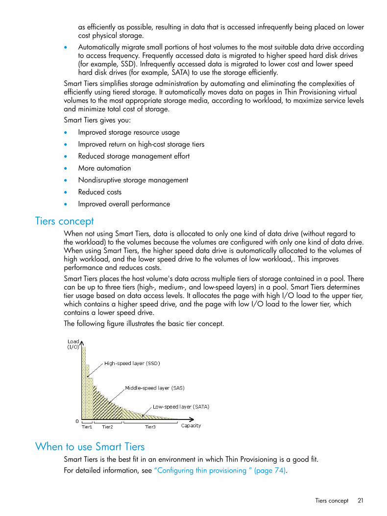
as efficiently as possible, resulting in data that is accessed infrequently being placed on lowercost physical storage.
• Automatically migrate small portions of host volumes to the most suitable data drive accordingto access frequency. Frequently accessed data is migrated to higher speed hard disk drives(for example, SSD). Infrequently accessed data is migrated to lower cost and lower speedhard disk drives (for example, SATA) to use the storage efficiently.
Smart Tiers simplifies storage administration by automating and eliminating the complexities ofefficiently using tiered storage. It automatically moves data on pages in Thin Provisioning virtualvolumes to the most appropriate storage media, according to workload, to maximize service levelsand minimize total cost of storage.Smart Tiers gives you:
• Improved storage resource usage
• Improved return on high-cost storage tiers
• Reduced storage management effort
• More automation
• Nondisruptive storage management
• Reduced costs
• Improved overall performance
Tiers conceptWhen not using Smart Tiers, data is allocated to only one kind of data drive (without regard tothe workload) to the volumes because the volumes are configured with only one kind of data drive.When using Smart Tiers, the higher speed data drive is automatically allocated to the volumes ofhigh workload, and the lower speed drive to the volumes of low workload,. This improvesperformance and reduces costs.Smart Tiers places the host volume's data across multiple tiers of storage contained in a pool. Therecan be up to three tiers (high-, medium-, and low-speed layers) in a pool. Smart Tiers determinestier usage based on data access levels. It allocates the page with high I/O load to the upper tier,which contains a higher speed drive, and the page with low I/O load to the lower tier, whichcontains a lower speed drive.The following figure illustrates the basic tier concept.
When to use Smart TiersSmart Tiers is the best fit in an environment in which Thin Provisioning is a good fit.For detailed information, see “Configuring thin provisioning ” (page 74).
Tiers concept 21

Data retention strategiesAfter provisioning your system, you can assign access attributes to open-system volumes to protectthe volume against read, write, and copy operations and to prevent users from configuring LUpaths and command devices. Use the Data Retention to assign access attributes.For more information, see “Configuring access attributes” (page 164).
Resource groups strategiesA storage system can connect to multiple hosts and be shared by multiple divisions in a companyor by multiple companies. Many storage administrators from different organizations can accessthe storage system. Managing the entire storage system can become complex and difficult. Potentialproblems are that private data might be accessed by other users, or a volume in one organizationmight be destroyed by mistake by a storage administrator in another organization.To avoid such problems, use Resource Partition to set up resource groups that allow you to manageone storage system as multiple virtual private storage systems. The storage administrator in eachresource group can access only their assigned resources and cannot access other resources.Configuring resource groups prevents the risk of data leakage or data destruction by anotherstorage administrator in another resource group.The resources such as LDEVs, parity groups, external volumes, ports, or host groups can be assignedto a resource group. These resources can be combined to flexibly compose a virtual private storagesystem.Resource groups should be planned and created before creating volumes. For more information,see “Configuring resource groups” (page 26).
Complimentary strategies
Functions related to provisioningFor the following functions, see the appropriate manuals:
• Replication: Business Copy, Continuous Access Synchronous, Continuous Access Journal
• External storage: External Storage
• Migration: Auto LUN (contact HP Technical Support)
• Partitioning: Cache Partition (HP XP P9000 Performance for Open and Mainframe SystemsUser Guide)
Key termsThe following are provisioning key terms:
DescriptionTerm
Security function used to control the access to a logical volume. Access attributes areassigned to each volume: read only, read/write, and protect.
access attributes
Customized Volume. A fixed volume that is divided into arbitrary sizes.CV (variable volume)
Security option used to allow or not allow changing of the access attribute on a volume.expiration lock
Abbreviation for fixed-sized volume.FV
Logical Unit Size Expansion (LUSE).LUSE
A set of LDEVs defined to one or more hosts as a single logical unit (LU). A LUSE volumecan be a concatenation of two to 36 LDEVs that are then presented to a host as a singleLU.
LUSE volume
22 Introduction to provisioning

DescriptionTerm
A resource group in which additional resources (other than external volumes) and theresources existing before installing Resource Partition belong.
meta_resource
In Thin Provisioning, a page is 42 MB of continuous storage in a THP V-VOL that belongsto a THP-pool.
page
A set of volumes that are reserved for storing Thin Provisioning, Fast Snap, or Snapshotwrite data.
pool
In a thin provisioned storage system, the proportion (%) of used capacity of the pool tothe total pool capacity. Each pool has its own pool threshold values for warning anddepletion.
pool threshold
A volume that is reserved for storing snapshot data for Snapshot operations or write datafor Thin Provisioning.
pool-VOL, pool volume
A group that is assigned one or more resources of the storage system. The resources thatcan be assigned to the resource group are LDEV IDs, parity groups, external volumes,ports, and host group IDs.
resource group
In a thin provisioned storage system, the proportion (%) of total THP-VOL capacityassociated with the pool versus the total capacity.
subscription threshold
You can set the percentage of THP-VOL capacity that can be created to the total capacityof the pool. This can help prevent THP-VOL blocking caused by a full pool.For example, when the subscription limit is set to 100%, the total THP-VOL capacity thatcan be created is obtained using this formula:total THP-VOL capacity <= pool capacity x 100%Using this setting protects the pool when doing the following:
• Shrinking a pool
• Creating THP-VOLs
• Increasing THP-VOL capacity
The value of the reached maximum I/O counts that each tier can process.tier boundary
A combination of determining the appropriate storage tier and migrating the pages tothe appropriate tier.
tier relocation
A storage hierarchy of layered structures of data drives consisting of different performancelevels, or tiers, that match data access requirements with the appropriate performancetiers.
tiered storage
A virtual device in the storage system. A VDEV is a group of logical volumes (LDEVs orlogical units) in a parity group. One parity group consists of multiple VDEVs. A VDEV
VDEV
usually includes some fixed volumes (FVs) and some free spaces. The number of FVs isdetermined by the emulation type.
Before you beginBefore you begin provisioning your P9500 storage system, certain requirements must be met.
System requirements• The P9500 hardware, microcode, and Remote Web Console essential for operating the
storage system be installed and configured for use.• A P9500 storage system.
• The storage system must have parity groups installed.
• A Remote Web Console client computer.
Before you begin 23

Shared memory requirementsIf configuring thin provisioning, Thin Provisioning requires dedicated shared memory for the V-VOLmanagement area.The V-VOL management area, which is automatically created when shared memory is added, isan area used to store information for associating pool-VOLs and THP V-VOLs.If Thin Provisioning is used, at least 16 GB of shared memory consisting of two sections is required.The memory capacity allocated to each part is as follows:
• Basic part: 8 GB
• Thin Provisioning: 8 GBIf Smart Tiers is used, shared memory for Thin Provisioning and Smart Tiers is necessary. At least24 GB of shared memory consisting of two sections is required. The memory capacity allocatedto each part is as follows:
• Basic part: 8 GB
• Thin Provisioning: 8 GB
• Smart Tiers: 8 GBIf Thin Provisioning and Smart Tiers are used, a pool or V-VOL capacity can be created and theshared memory can be expanded depending on its status. If you use a pool or V-VOL which hasa capacity greater than 1.1 PB, the shared memory must be installed. Before the shared memoryis uninstalled, all Thin Provisioning and Smart Tiers pools must be deleted.The required shared memory is installed by your HP representative.
About cache management devicesCache management devices are associated with volumes (LDEVs) and used to manage caches.One volume (LDEV) requires at least one cache management device. An entire system can manageup to 65,280 cache management devices. A THP V-VOL may require more than one cachemanagement device. This topic describes how to calculate the number of cache managementdevices.
Calculating the number of cache management devices required by a THP V-VOLThe number of cache management devices that a THP V-VOL requires depends on the capacity ofthe V-VOL (capacity of the user area) and the maximum capacity of cache management device.The maximum capacity of cache management device depends on the pool attribute (internal volumeor external volume) associated with V-VOL. The following table explains the relationship betweenthe pool attribute and the maximum capacity of cache management device.
Maximum capacity of cache management device
Maximum capacity(in blocks)
Maximum capacity(in MB)
Pool attribute
6,442,426,3683,145,716Internal volume(2.99 TB)
6,442,426,3683,145,716External volume with Mixable set toEnabled (2.99 TB)
8,589,901,8244,194,288External volume with Mixable set toDisabled (3.99 TB)
24 Introduction to provisioning

Use the following formula to calculate the number of cache management devices that a THP V-VOLrequires. In this formula, the user-specified capacity is the user area capacity of a V-VOL.ceil(user-specified capacity ÷ max-capacity-of-cache-management-device)The calculated value must be rounded up to the nearest whole number.
Calculating the number of cache management devices required by a volume that isnot a THP V-VOL
One volume that is not a THP V-VOL requires one cache management device.
Viewing the number of cache management devicesClick Actions and select View Management Resource Usage to display the number of cachemanagement devices in the View Management Resource Usage window. For details, see “Aboutcache management devices” (page 24) and “View Management Resource Usage window”(page 290).
About cache management devices 25
2 Configuring resource groupsThe Storage Administrator can divide a provisioned storage system into resource groups that allowmanaging the storage system as multiple virtual private storage systems. Configuring resourcegroups involves creating resource groups, moving storage system resources into the resourcegroups, and assigning resource groups to user groups.Resource groups can be set up on both open and mainframe systems. Resource Partition softwareis required.
System configuration using resource groupsConfiguring resource groups prevents the risk of data leakage or data destruction by anotherStorage Administrator in another resource group. The Storage Administrator considers and planswhich resource should be managed by which user, and then the Security Administrator createsresource groups and assigns each resource to the resource groups.A resource group is assigned one or more storage system resources. The following resources canbe assigned to resource groups.
• LDEV IDs*
• Parity groups
• External volumes (VDEVs)
• Ports
• Host group IDs** Before you create LDEVs, the LDEV IDs can be reserved and assigned to a resource group forfuture use. Host group numbers can also be reserved and assigned in advance because the numberof host groups created on a single port is limited.The following tasks provide instructions for configuring resource groups.
• “Creating a resource group” (page 30)
• “Adding resources to a resource group” (page 31)
• “Removing resources from a resource group” (page 32)
• “Changing the name of a resource group” (page 32)
• “Deleting a resource group” (page 33)
Resource groups examplesThe following examples illustrate how you can configure resource groups on your storage system:
• “Example of resource groups sharing a port” (page 26)
• “Example of resource groups not sharing ports” (page 28)
Example of resource groups sharing a portIf you have a limited number of ports, you can still operate a storage system effectively by sharingports using resource groups.The following example shows the system configuration of an in-house division providing virtualprivate storage system for two divisions. Divisions A and B each use their own assigned paritygroup, but share a port between the two divisions. The shared port is managed by the systemdivision.
26 Configuring resource groups

The Security Administrator in the system division creates resource groups for each division in thestorage system and assigns them to the respective divisions. The Storage Administrator in DivisionA can manage the resource groups for Division A, but cannot access the resource groups forDivision B. In the same manner, the Storage Administrator in Division B can manage the resourcegroups for Division B, but cannot access the resource groups for Division A.The Security Administrator creates a resource group for managing the common resources, and theStorage Administrator in the system division manages the port that is shared between Divisions Aand B. The Storage Administrators in Divisions A and B cannot manage the shared port belongingto the resource group for common resources management.
Configuration workflow for resource groups sharing a port1. The system division forms a plan about the resource group creation and assignment of the
resources.2. The Security Administrator creates resource groups.
See “Creating a resource group” (page 30) for more information.3. The Security Administrator creates user groups.
See the HP XP P9000 Remote Web Console User Guide for more information.4. The Security Administrator assigns the resource groups to user groups.
See the HP XP P9000 Remote Web Console User Guide for more information.5. The Storage Administrator in the system division sets a port.6. The Security Administrator assigns resources to the resource groups.
See “Adding resources to a resource group” (page 31) for more information.7. The Security Administrator assigns each Storage Administrator to each user group.
See the HP XP P9000 Remote Web Console User Guide for more information.
After the above procedures, the Storage Administrators in A and B divisions can manage theresource groups assigned to their own division.
Resource groups examples 27

Example of resource groups not sharing portsIf you assign ports to each resource group without sharing, performance can be maintained on adifferent port even if the bulk of I/O is issued from one side port.The following shows a system configuration example of an in-house system division providing thevirtual private storage system for two divisions. Divisions A and B each use individual assignedports and parity groups. In this example, they do not share a port.
The Security Administrator in the system division creates resource groups for each division in thestorage system and assigns them to the respective divisions. The Storage Administrator in DivisionA can manage the resource groups for Division A, but cannot access the resource groups forDivision B. In the same manner, the Storage Administrator in Division B can manage the resourcegroups for Division B, but cannot access the resource groups for Division A.
Configuration workflow for resource groups not sharing a port1. The system division forms a plan about creating resource groups and the assigning resources
to the groups.2. The Security Administrator creates resource groups.
See “Creating a resource group” (page 30)) for more information.3. The Security Administrator creates user groups.
See the HP XP P9000 Remote Web Console User Guide for more information.4. The Security Administrator assigns the resource groups to user groups.
See the HP XP P9000 Remote Web Console User Guide for more information.5. The Storage Administrator in the system division sets ports.6. The Security Administrator assigns resources to the resource groups.
See “Adding resources to a resource group” (page 31) for more information.7. The Security Administrator assigns each Storage Administrator to each user group.
See the HP XP P9000 Remote Web Console User Guide for more information.
28 Configuring resource groups

After the above procedures, the Storage Administrators in A and B divisions can access the resourcegroups allocated to their own division.
Meta_resourceThe meta_resource is a resource group comprised of additional resources (other than externalvolumes) and the resources that exist on the storage system before the Resource Partition is installed.By default, existing resources initially belong to the meta_resource group to ensure compatibilitywith older software when a system is upgraded to include Resource Partition.
Resource lockWhile processing a task on a resource, all of the resource groups assigned to the logged-on userare locked for exclusive access.A secondary window (such as the Basic Information Display) or an operation from the serviceprocessor (SVP) locks all of the resource groups in the storage system.When a resource is locked, a status indicator appears on the Remote Web Console status bar.Click the Resource Locked button to view information about the locked resource.
User groupsUser groups and associated built-in roles are defined in the SVP. A user belongs to one or moreuser groups. Privileges allowed to a particular user are determined by the user group or groupsto which the user belongs.The Security Administrator assigns resource groups to user groups. A user group may already beconfigured, or a new user group may be required for certain resources.See the HP XP P9000 Remote Web Console User Guide for more information about how to setup user groups.
Resource group assignmentsAll resource groups are normally assigned to the Security Administrator and the Audit LogAdministrator.Each resource group has a designated Storage Administrator who can access only their assignedresources and cannot access other resources.All resource groups to which all resources in the storage system belong can be assigned to a usergroup. Configure this in Remote Web Console by setting All Resource Groups Assigned to Yes.A user who has All Resource Groups Assigned set to Yes can access all resources in the storagesystem. For example, if a user is a Security Administrator (with View & Modify privileges) and aStorage Administrator (with View and Modify privileges) and All Resource Groups Assigned is Yeson that user account, the user can edit the storage for all the resources.If allowing this access becomes a problem with security on the storage system, then register thefollowing two user accounts in Remote Web Console and use these different accounts for differentpurposes.
• A user account for a Security Administrator where All Resource Groups Assigned is set to Yes.
• A user account for a Storage Administrator who does not have all resource groups assignedand has only some of the resource groups assigned.
Meta_resource 29

Resource group license requirementsUse of Resource Partition on the P9500 storage system requires the following:
• A license key on the Remote Web Console computer for Resource Partition software. Fordetails about the license key or product installation, see the HP XP P9000 Remote Web ConsoleUser Guide.
Resource group rules, restrictions, and guidelines
Rules• The maximum number of resource groups that can be created on a storage system is 1023.
• A Storage Administrator with the Security Administrator (View & Modify) role can createresource groups and assign resources to resource groups.
• Resources removed from a resource group are returned to meta_resource.
• Only a Storage Administrator (View & Modify) can manage the resources in assigned resourcegroups.
Restrictions• No new resources can be added to meta_resource.
• Resources cannot be deleted from meta_resource.
• An LDEV that has the same pool ID or the journal group ID cannot be added to multipleresource groups.In the case of adding LDEVs that are used as pool volumes or journal volumes, add all theLDEVs that have the same pool IDs or journal group IDs by using a function such as sort.
• Host groups that belong to the initiator port cannot be added to a resource group.
Guidelines• If you are providing a virtual private storage system to different companies, you should not
share parity groups, external volumes, or pools if you want to limit the capacity that can beused by each user. When parity groups, external volumes, or pools are shared betweenmultiple users, and if one user uses too much capacity of the shared resource, the other usersmight not be able to create an LDEV.
Creating a resource groupWhen creating a resource group, observe the following:
• The maximum number of resource groups that can be created on a storage system is 1023.
• The name meta_resource cannot be set for a resource group name.
• Duplicate occurrences of the same name are not allowed.
• Resource group name can use alphanumeric characters, spaces, and the following symbols:! # $ % & ' ( ) + - . = @ [ ] ^ _ ` { } ~
• Alphabets are case-sensitive.
• You must have Security Administrator (View & Modify) role to perform this task.Procedure 1 To create a resource group1. In the Remote Web Console main window, in the Storage Systems tree, click Administration,
and then Resource Groups.2. Click Create Resource Groups in the Resource Groups tab.
30 Configuring resource groups
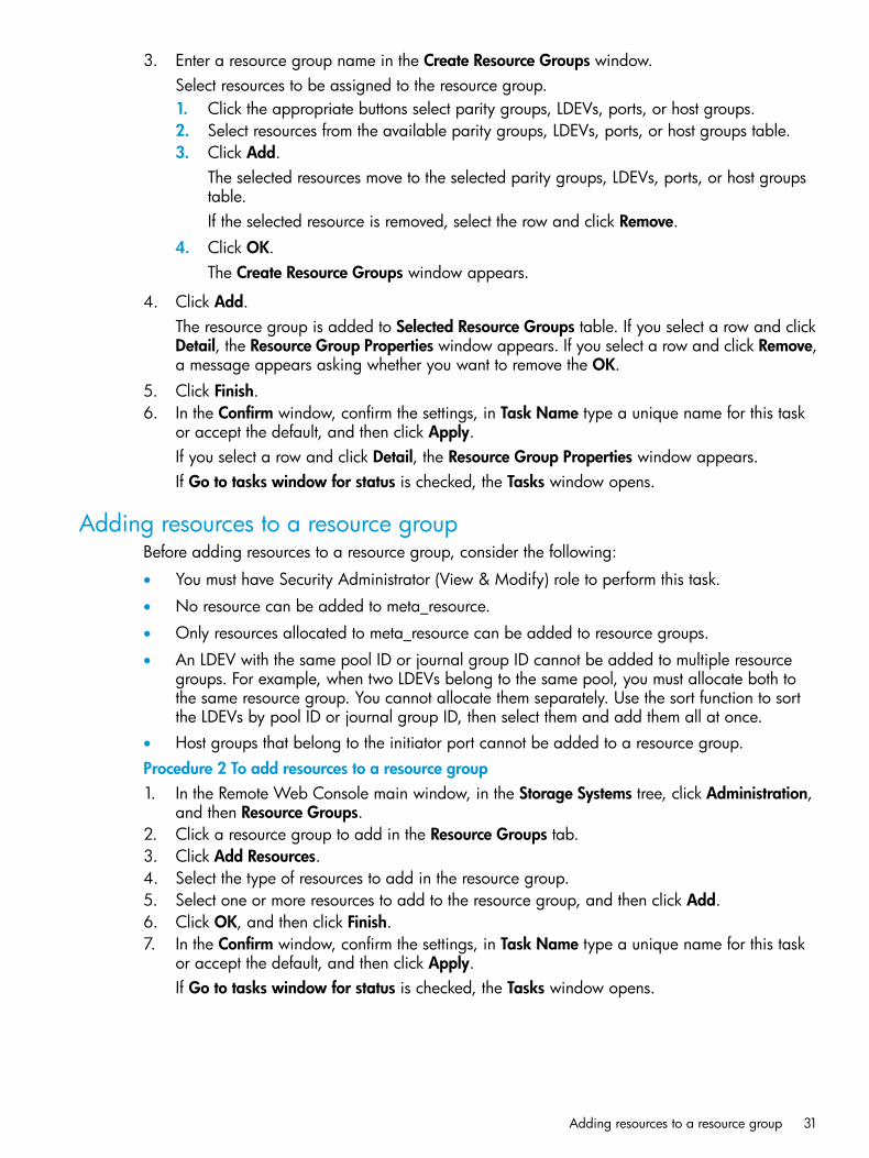
3. Enter a resource group name in the Create Resource Groups window.Select resources to be assigned to the resource group.1. Click the appropriate buttons select parity groups, LDEVs, ports, or host groups.2. Select resources from the available parity groups, LDEVs, ports, or host groups table.3. Click Add.
The selected resources move to the selected parity groups, LDEVs, ports, or host groupstable.If the selected resource is removed, select the row and click Remove.
4. Click OK.The Create Resource Groups window appears.
4. Click Add.The resource group is added to Selected Resource Groups table. If you select a row and clickDetail, the Resource Group Properties window appears. If you select a row and click Remove,a message appears asking whether you want to remove the OK.
5. Click Finish.6. In the Confirm window, confirm the settings, in Task Name type a unique name for this task
or accept the default, and then click Apply.If you select a row and click Detail, the Resource Group Properties window appears.If Go to tasks window for status is checked, the Tasks window opens.
Adding resources to a resource groupBefore adding resources to a resource group, consider the following:
• You must have Security Administrator (View & Modify) role to perform this task.
• No resource can be added to meta_resource.
• Only resources allocated to meta_resource can be added to resource groups.
• An LDEV with the same pool ID or journal group ID cannot be added to multiple resourcegroups. For example, when two LDEVs belong to the same pool, you must allocate both tothe same resource group. You cannot allocate them separately. Use the sort function to sortthe LDEVs by pool ID or journal group ID, then select them and add them all at once.
• Host groups that belong to the initiator port cannot be added to a resource group.Procedure 2 To add resources to a resource group1. In the Remote Web Console main window, in the Storage Systems tree, click Administration,
and then Resource Groups.2. Click a resource group to add in the Resource Groups tab.3. Click Add Resources.4. Select the type of resources to add in the resource group.5. Select one or more resources to add to the resource group, and then click Add.6. Click OK, and then click Finish.7. In the Confirm window, confirm the settings, in Task Name type a unique name for this task
or accept the default, and then click Apply.If Go to tasks window for status is checked, the Tasks window opens.
Adding resources to a resource group 31

Removing resources from a resource groupBefore removing remove resources from a resource group, consider the following:
• The resources removed from a resource group are returned to meta_resource.
• Resources cannot be deleted from the meta_resource.
• An LDEV that has the same pool ID or journal group ID cannot be partially removed. Forexample, if two LDEVs belong to the same pool, you cannot remove only LDEV1 from theresource group and leave only LDEV2. Use the sort function to sort the LDEVs by pool ID orjournal group ID, then select them and remove them all at once.
• You must have Security Administrator (View & Modify) role to perform this task.Procedure 3 To remove resources from a resource group1. In the Remote Web Console main window, in the Storage Systems tree, click Administration,
and then Resource Groups.2. Click a resource group to remove in the Resource Groups tab.3. Select one or more resources to remove from the resource group, and then click Remove
Resources.4. In the Confirm window, confirm the settings, in Task Name type a unique name for this task
or accept the default, and then click Apply.If Go to tasks window for status is checked, the Tasks window opens.
Managing Resource Groups
Changing the name of a resource groupWhen changing the name of a resource group, observe the following:
• The name meta_resource cannot be changed.
• Duplicate occurrences of the same name are not allowed.
• The name of meta_resource cannot be set for a resource group name.
• Resource group names can use alphanumeric characters, spaces, and the following symbols:! # $ % & ' ( ) + - . = @ [ ] ^ _ ` { } ~
• Alphabets are case-sensitive.
• You must have Security Administrator (View & Modify) role to perform this task.Procedure 4 To change a resource group name1. In the Remote Web Console main window, in the Storage Systems tree, click Administration,
and then Resource Groups.2. Click a resource group to change its name in the Resource Groups tab.3. Click Edit Resource Group.4. In the Edit Resource Group window, type a new resource group name, and then click Finish.5. In the Confirm window, confirm the settings, in Task Name type a unique name for this task
or accept the default, and then click Apply.If you select a row and click Detail, the Resource Group Properties window appears.If Go to tasks window for status is checked, the Tasks window opens.
32 Configuring resource groups

Deleting a resource groupYou cannot delete the following:
• The meta_resource.
• A resource group that is assigned to a user group.
• A resource group that has resources assigned to it.Procedure 5 To delete a resource group1. In the Remote Web Console main window, in the Storage Systems tree, click Administration,
and then Resource Groups.2. Click one or more resource groups to delete in the Resource Groups tab.3. Click Delete Resource Groups.4. In the Confirm window, confirm the settings, in Task Name type a unique name for this task
or accept the default, and then click Apply.If Go to tasks window for status is checked, the Tasks window opens.
Using Resource Partition and other P9500 productsTo use Resource Partition with other P9500 products, the resources that are required for theoperation must satisfy specific conditions. The following topics provide information about thespecific resource conditions that are required for using each P9500 product.
• “Snapshot” (page 34)
• “Thin Provisioning” (page 34)
• “DKA Encryption” (page 35)
• “External Storage Access Manager” (page 35)
• “LUN Expansion” (page 35)
• “LUN Manager” (page 36)
• “Performance Monitor” (page 37)
• “Fast Snap” (page 37)
• “Continuous Access Synchronous” (page 38)
• “Continuous Access Journal” (page 39)
• “External Storage” (page 40)
• “Open Volume Management” (page 41)
• “Cache Partition” (page 41)
• “Auto LUN” (page 41)
• “Volume Shredder” (page 42)
• “Configuration File Loader” (page 42)
• “CLI Spreadsheet for LUN Expansion” (page 42)
• “Performance Control” (page 43)
Using Resource Partition and other P9500 products 33
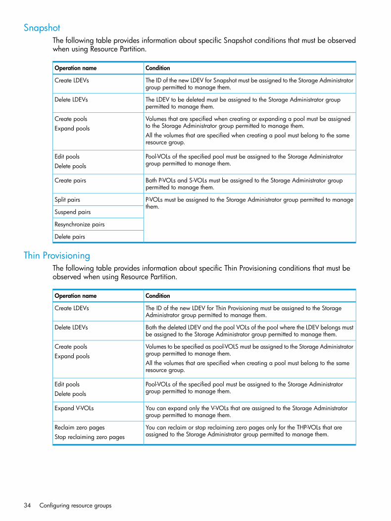
SnapshotThe following table provides information about specific Snapshot conditions that must be observedwhen using Resource Partition.
ConditionOperation name
The ID of the new LDEV for Snapshot must be assigned to the Storage Administratorgroup permitted to manage them.
Create LDEVs
The LDEV to be deleted must be assigned to the Storage Administrator grouppermitted to manage them.
Delete LDEVs
Volumes that are specified when creating or expanding a pool must be assignedto the Storage Administrator group permitted to manage them.
Create poolsExpand pools
All the volumes that are specified when creating a pool must belong to the sameresource group.
Pool-VOLs of the specified pool must be assigned to the Storage Administratorgroup permitted to manage them.
Edit poolsDelete pools
Both P-VOLs and S-VOLs must be assigned to the Storage Administrator grouppermitted to manage them.
Create pairs
P-VOLs must be assigned to the Storage Administrator group permitted to managethem.
Split pairs
Suspend pairs
Resynchronize pairs
Delete pairs
Thin ProvisioningThe following table provides information about specific Thin Provisioning conditions that must beobserved when using Resource Partition.
ConditionOperation name
The ID of the new LDEV for Thin Provisioning must be assigned to the StorageAdministrator group permitted to manage them.
Create LDEVs
Both the deleted LDEV and the pool VOLs of the pool where the LDEV belongs mustbe assigned to the Storage Administrator group permitted to manage them.
Delete LDEVs
Volumes to be specified as pool-VOLS must be assigned to the Storage Administratorgroup permitted to manage them.
Create poolsExpand pools
All the volumes that are specified when creating a pool must belong to the sameresource group.
Pool-VOLs of the specified pool must be assigned to the Storage Administratorgroup permitted to manage them.
Edit poolsDelete pools
You can expand only the V-VOLs that are assigned to the Storage Administratorgroup permitted to manage them.
Expand V-VOLs
You can reclaim or stop reclaiming zero pages only for the THP-VOLs that areassigned to the Storage Administrator group permitted to manage them.
Reclaim zero pagesStop reclaiming zero pages
34 Configuring resource groups

DKA EncryptionThe following table provides information about specific DKA Encryption conditions that must beobserved when using Resource Partition.
ConditionOperation name
When you specify a parity group and open the Edit Encryption window, thespecified parity group and LDEVs belonging to the parity group must be assignedto the Storage Administrator group permitted to manage them.
Edit encryption keys
When you open the Edit Encryption window without specifying a parity group,more than one parity group and LDEVs belonging to the parity group must beassigned to the Storage Administrator group permitted to manage them.
External Storage Access ManagerThe following table provides information about specific External Storage Access Manager conditionsthat must be observed when using Resource Partition.The system configuration for resource group settings should be the same for External Storage AccessManager in both the primary and secondary sites.
ConditionOperation name
P-VOLs and quorum disks must be assigned to the Storage Administrator grouppermitted to manage them.
Create pairs
Initiator ports for the logical paths that are configured between P-VOLs and theRCU must be assigned to the Storage Administrator group permitted to managethem.
P-VOLs must be assigned to the Storage Administrator group permitted to managethem.
Change pair options
The specified P-VOLs or S-VOLs must be assigned to the Storage Administratorgroup permitted to manage them.
Split pairs
P-VOLs must be assigned to the Storage Administrator group permitted to managethem.
Resynchronize pairs
The specified P-VOLs or S-VOLs must be assigned to the Storage Administratorgroup permitted to manage them.
Release pairs
Quorum disks must be assigned to the Storage Administrator group permitted tomanage them.When you specify P-VOLs, initiator ports for the logical paths that are configuredbetween P-VOLs and RCU must be assigned to the Storage Administrator grouppermitted to manage them.
The specified LDEV must be assigned to the Storage Administrator group permittedto manage them.
Add quorum disksDelete quorum disks
LUN ExpansionThe following table provides information about specific LUN Expansion conditions that must beobserved when using Resource Partition.
ConditionOperation name
The LDEVs specified when creating a LUSE volume must all belong to the sameresource group as the LUSE volume.
Create LUSE volumes
Using Resource Partition and other P9500 products 35

LUN ManagerThe following table provides information about specific LUN Manager conditions that must beobserved when using Resource Partition.
ConditionOperation name
When you specify host groups and open the Add LUN Paths window, the specifiedhost groups must be assigned to the Storage Administrator group permitted tomanage them.
Add LUN paths
When you specify LDEVs and open the Add LUN paths window, the specifiedLDEVs must be assigned to the Storage Administrator group permitted to managethem.
When you specify a host group and open the Delete LUN Paths window, thespecified host group must be assigned to the Storage Administrator group permittedto manage them.
Delete LUN paths
When you specify LDEVs and open the Delete LUN Paths window, the specifiedLDEVs must be assigned to the Storage Administrator group permitted to managethem.When selecting the Delete all defined LUN paths to above LDEVs check box, thehost groups of all the alternate paths in the LDEV displayed on the Selected LUNstable must be assigned to the Storage Administrator group permitted to managethem.
The specified host groups and initiator ports must be assigned to the StorageAdministrator group permitted to manage them.
Edit host groups
The specified host groups must be assigned to the Storage Administrator grouppermitted to manage them.
Add hosts
The specified host group must be assigned to the Storage Administrator grouppermitted to manage them.
Edit hosts
When you select the Apply same settings to the HBA WWN of all ports check box,all the host groups where the specified HBA WWNs are registered must be assignedto the Storage Administrator group permitted to manage them.
When you select the Remove hosts from all host groups containing the hosts in thestorage system check box, all the host groups where the HBA WWNs displayed
Remove hosts
in the Selected Hosts table are registered must be assigned to the StorageAdministrator group permitted to manage them.
The specified port must be assigned to the Storage Administrator group permittedto manage them.
Edit ports
If this port attribute is changed from Target or RCU Target to Initiator or to External,the host group of this port belongs to meta_resource.Therefore, the host group of this port is not displayed in windows.
The specified host groups and all the LDEVs where the paths are set to the hostgroups must be assigned to the Storage Administrator group permitted to managethem.
Create alternative LUN paths
The specified host groups and the LDEVs where the paths are set must be assignedto the Storage Administrator group permitted to manage them.
Copy LUN paths
LDEVs where the specified paths are set must be assigned to the StorageAdministrator group permitted to manage them.
Edit command devices
The specified LDEV must be assigned to the Storage Administrator group permittedto manage them.
Edit UUIDs
The specified LDEV must be assigned to the Storage Administrator group permittedto manage them.
Delete UUIDs
36 Configuring resource groups

ConditionOperation name
When you open the Create Host Groups window by specifying host groups, thespecified host groups must be assigned to the Storage Administrator group permittedto manage them.
Create host groups
The specified host groups and all the LDEVs where the paths are set to the hostgroups must be assigned to the Storage Administrator group permitted to managethem.
Delete host groups
LDEVs where the specified paths are set must be assigned to you.Release Host-Reserved LUNs
Performance MonitorThe following table provides information about specific Performance Monitor conditions that mustbe observed when using Resource Partition.
ConditionOperation name
The specified ports must be assigned to the Storage Administrator group permittedto manage them.
Add to ports
The specified ports must be assigned to the Storage Administrator group permittedto manage them.
Add new monitored WWNs
The specified ports must be assigned to the Storage Administrator group permittedto manage them.
Edit WWNs
Business CopyThe following table provides information about specific Business Copy conditions that must beobserved when using Resource Partition.
ConditionOperation name
Both P-VOLs and S-VOLs must be assigned to the Storage Administrator grouppermitted to manage them.
Create pairs
P-VOLs must be assigned to the Storage Administrator group permitted to managethem.
Split pairs
Suspend pairs
Resynchronize pairs
Release pairs
The specified LDEVs must be assigned to the Storage Administrator group permittedto manage them.
Set reserve attributesRemove reserve attributes
Fast SnapThe following table provides information about specific Fast Snap conditions that must be observedwhen using Resource Partition.
ConditionOperation name
When you create LDEVs for Snapshot, IDs of the LDEVs that you will create mustbe assigned to you.
Create LDEVs
Deleted LDEVs must be assigned to you.Delete LDEVs
Volumes that are specified when creating or expanding pools must be assignedto you.
Create poolsExpand Pool
Using Resource Partition and other P9500 products 37

ConditionOperation name
All the volumes that are specified when creating pools must belong to the sameresource group.
Pool-VOLs of the specified pools must be assigned to you.Edit PoolsDelete Pools
Both P-VOLs and S-VOLs must be assigned to you.Create pairs
P-VOLs must be assigned to you.Split pairs
Suspend pairs
Resynchronize pairs
Release pairs
Continuous Access SynchronousThe following table provides information about specific Continuous Access Synchronous conditionsthat must be observed when using Resource Partition.
ConditionOperation name
P-VOLs must be assigned to the Storage Administrator group permitted to managethem.
Create pairs
Initiator ports for the logical paths that are configured between P-VOLs and RCUmust be assigned to the Storage Administrator group permitted to manage them.
P-VOLs must be assigned to the Storage Administrator group permitted to managethem.
Change pair options
The specified P-VOLs or S-VOLs must be assigned to the Storage Administratorgroup permitted to manage them.
Split pairs
P-VOLs must be assigned to the Storage Administrator group permitted to managethem.
Resynchronize pairs
The specified P-VOLs or S-VOLs must be assigned to the Storage Administratorgroup permitted to manage them.
Release pairs
When you specify P-VOLs, initiator ports for the logical paths that are configuredbetween P-VOLs and RCU must be assigned to the Storage Administrator grouppermitted to manage them.
The specified ports must be assigned to the Storage Administrator group permittedto manage them.
Define port attributes
The specified initiator ports must be assigned to the Storage Administrator grouppermitted to manage them.
Add RCUs
Initiator ports of logical paths to the specified RCUs must be assigned to the StorageAdministrator group permitted to manage them.
Delete RCUsChange RCU options
The specified initiator ports must be assigned to the Storage Administrator grouppermitted to manage them.
Add logical pathsDelete logical paths
Initiator ports of logical paths to the specified RCUs must be assigned to the StorageAdministrator group permitted to manage them.
Add SSIDsDelete SSIDs
38 Configuring resource groups

Continuous Access JournalThe following table provides information about specific Continuous Access Journal conditions thatmust be observed when using Resource Partition.
ConditionOperation name
All the LDEVs that are specified when creating a journal must belong to the sameresource group.
Create journal volumes
All the specified LDEVs when adding journal volumes must belong to the sameresource group where existing journal volumes belong.
Add journal volumesDelete journal volumes
All the data volumes in the specified journals must be assigned to the StorageAdministrator group permitted to manage them.
Change journal options
Journal volumes for pair volumes and P-VOLs must be assigned to the StorageAdministrator group permitted to manage them.
Create pairs
Initiator ports of logical paths to remote storage systems must be assigned to theStorage Administrator group permitted to manage them.
P-VOLs must be assigned to the Storage Administrator group permitted to managethem.
Change pair options
The specified P-VOLs or S-VOLs must be assigned to the Storage Administratorgroup permitted to manage them.
Split pairs
P-VOLs must be assigned to the Storage Administrator group permitted to managethem.
Restore pairs
The specified P-VOLs or S-VOLs must be assigned to the Storage Administratorgroup permitted to manage them.
Delete pairs
Initiator ports of logical paths to remote storage systems must be assigned to theStorage Administrator group permitted to manage them.
All the data volumes in the specified mirrors must be assigned to the StorageAdministrator group permitted to manage them.
Change mirror options
The specified ports must be assigned to the Storage Administrator group permittedto manage them.
Define port attributes
The specified initiator ports must be assigned to the Storage Administrator grouppermitted to manage them.
Add remote DKCs
Initiator ports of logical paths to the specified remote storage systems must beassigned to the Storage Administrator group permitted to manage them.
Delete remote DKCs
Initiator ports of logical paths to the specified remote storage systems must beassigned to the Storage Administrator group permitted to manage them.
Change remote DKC options
The specified initiator ports must be assigned to the Storage Administrator grouppermitted to manage them.
Add logical paths
The specified initiator ports must be assigned to the Storage Administrator grouppermitted to manage them.
Delete logical paths
When you move LDEVs used for journal volumes to other resource groups, youmust specify all the journal volumes of the journal where the LDEVs belong.
Move LDEVs to other resourcegroups
Using Resource Partition and other P9500 products 39
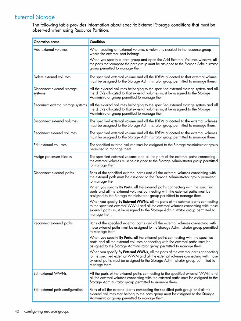
External StorageThe following table provides information about specific External Storage conditions that must beobserved when using Resource Partition.
ConditionOperation name
When creating an external volume, a volume is created in the resource groupwhere the external port belongs.
Add external volumes
When you specify a path group and open the Add External Volumes window, allthe ports that compose the path group must be assigned to the Storage Administratorgroup permitted to manage them.
The specified external volume and all the LDEVs allocated to that external volumemust be assigned to the Storage Administrator group permitted to manage them.
Delete external volumes
All the external volumes belonging to the specified external storage system and allthe LDEVs allocated to that external volumes must be assigned to the StorageAdministrator group permitted to manage them.
Disconnect external storagesystems
All the external volumes belonging to the specified external storage system and allthe LDEVs allocated to that external volumes must be assigned to the StorageAdministrator group permitted to manage them.
Reconnect external storage systems
The specified external volume and all the LDEVs allocated to the external volumesmust be assigned to the Storage Administrator group permitted to manage them.
Disconnect external volumes
The specified external volume and all the LDEVs allocated to the external volumesmust be assigned to the Storage Administrator group permitted to manage them.
Reconnect external volumes
The specified external volume must be assigned to the Storage Administrator grouppermitted to manage them.
Edit external volumes
The specified external volumes and all the ports of the external paths connectingthe external volumes must be assigned to the Storage Administrator group permittedto manage them.
Assign processor blades
Ports of the specified external paths and all the external volumes connecting withthe external path must be assigned to the Storage Administrator group permittedto manage them.
Disconnect external paths
When you specify By Ports, all the external paths connecting with the specifiedports and all the external volumes connecting with the external paths must beassigned to the Storage Administrator group permitted to manage them.When you specify By External WWNs, all the ports of the external paths connectingto the specified external WWN and all the external volumes connecting with thoseexternal paths must be assigned to the Storage Administrator group permitted tomanage them.
Ports of the specified external paths and all the external volumes connecting withthose external paths must be assigned to the Storage Administrator group permittedto manage them.
Reconnect external paths
When you specify By Ports, all the external paths connecting with the specifiedports and all the external volumes connecting with the external paths must beassigned to the Storage Administrator group permitted to manage them.When you specify By External WWNs, all the ports of the external paths connectingto the specified external WWN and all the external volumes connecting with thoseexternal paths must be assigned to the Storage Administrator group permitted tomanage them.
All the ports of the external paths connecting to the specified external WWN andall the external volumes connecting with the external paths must be assigned to theStorage Administrator group permitted to manage them.
Edit external WWNs
Ports of all the external paths composing the specified path group and all theexternal volumes that belong to the path group must be assigned to the StorageAdministrator group permitted to manage them.
Edit external path configuration
40 Configuring resource groups

Open Volume ManagementThe following table provides information about specific Open Volume Management conditionsthat must be observed when using Resource Partition.
ConditionOperation name
When you specify a parity group and open the Create LDEVs window, the paritygroup must be assigned to the Storage Administrator group permitted to managethem.
Create LDEVs
When you create an internal or external volumes parity groups where the LDEVbelongs and ID of the new LDEV must be assigned to the Storage Administratorgroup permitted to manage them.
When deleting an internal or external volume, the deleted LDEV and parity groupswhere the LDEV belongs must be assigned to the Storage Administrator grouppermitted to manage them.
Delete LDEVs
The specified LDEV must be assigned to the Storage Administrator group permittedto manage them.
Edit LDEVs
The specified LDEV must be assigned to the Storage Administrator group permittedto manage them.
Restore LDEVs
The specified LDEV must be assigned to the Storage Administrator group permittedto manage them.
Block LDEVs
When you specify LDEV and open the Format LDEVs window, the specified LDEVmust be assigned to the Storage Administrator group permitted to manage them.
Format LDEVs
When you specify a parity group and open the Format LDEVs window, the specifiedparity group and all the LDEVs in the parity group must be assigned to the StorageAdministrator group permitted to manage them.
Cache PartitionThe following table provides information about specific Cache Partition conditions that must beobserved when using Resource Partition.
ConditionOperation name
When you specify virtual volumes, the specified LDEV must be assigned to theStorage Administrator group permitted to manage them.
Migrate parity groups
When you specify a parity group, the specified parity group must be assigned tothe Storage Administrator group permitted to manage them.
Auto LUNThe following table provides information about specific Auto LUN conditions that must be observedwhen using Resource Partition.
ConditionOperation name
The specified source volume and target volume must be assigned to the StorageAdministrator group permitted to manage them.
Migrate volumes
The specified LDEV must be assigned to the Storage Administrator group permittedto manage them.
Reserve volumes
The specified parity group must be assigned to the Storage Administrator grouppermitted to manage them.
Fix parity groups
Using Resource Partition and other P9500 products 41
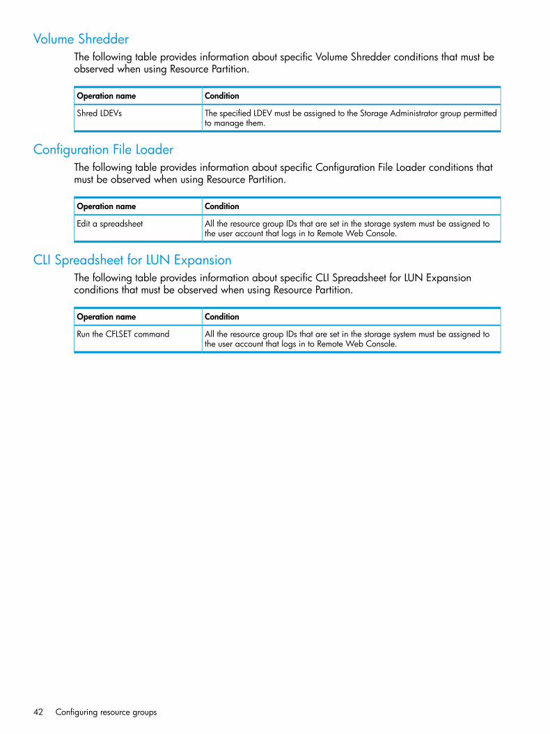
Volume ShredderThe following table provides information about specific Volume Shredder conditions that must beobserved when using Resource Partition.
ConditionOperation name
The specified LDEV must be assigned to the Storage Administrator group permittedto manage them.
Shred LDEVs
Configuration File LoaderThe following table provides information about specific Configuration File Loader conditions thatmust be observed when using Resource Partition.
ConditionOperation name
All the resource group IDs that are set in the storage system must be assigned tothe user account that logs in to Remote Web Console.
Edit a spreadsheet
CLI Spreadsheet for LUN ExpansionThe following table provides information about specific CLI Spreadsheet for LUN Expansionconditions that must be observed when using Resource Partition.
ConditionOperation name
All the resource group IDs that are set in the storage system must be assigned tothe user account that logs in to Remote Web Console.
Run the CFLSET command
42 Configuring resource groups
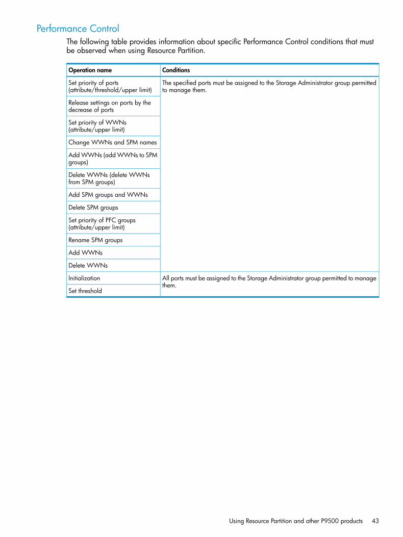
Performance ControlThe following table provides information about specific Performance Control conditions that mustbe observed when using Resource Partition.
ConditionsOperation name
The specified ports must be assigned to the Storage Administrator group permittedto manage them.
Set priority of ports(attribute/threshold/upper limit)
Release settings on ports by thedecrease of ports
Set priority of WWNs(attribute/upper limit)
Change WWNs and SPM names
Add WWNs (add WWNs to SPMgroups)
Delete WWNs (delete WWNsfrom SPM groups)
Add SPM groups and WWNs
Delete SPM groups
Set priority of PFC groups(attribute/upper limit)
Rename SPM groups
Add WWNs
Delete WWNs
All ports must be assigned to the Storage Administrator group permitted to managethem.
Initialization
Set threshold
Using Resource Partition and other P9500 products 43

3 Configuring custom-sized provisioningConfiguring custom-sized provisioning involves creating and configuring a customized volume(CV). A CV is a fixed-sized volume that is divided into arbitrary sizes.This provisioning strategy is suitable for use on both open and mainframe systems. Virtual LVI orVirtual LUN software is required to configure variable-sized provisioning.
Virtual LVI/Virtual LUN functionsVirtual LVI or Virtual LUN functions are used to create, configure, or delete a customized volume(LDEV).The Virtual LUN and the Virtual LVI function are collectively referred to as VLL. The only differencebetween the two functions is that Virtual LUN is an open systems function available in Open VolumeManagement software, while Virtual LVI is a mainframe function available in Virtual LVI software.A parity group usually consists of some fixed-sized volumes (FVs) and some free space. The numberof FVs is determined by the emulation type. A VLL volume usually consists of at least one FV, oneor more customized volumes (CVs), and some free space.You can use VLL to configure variable-sized volumes that efficiently exploit the capacity of a disk.Variable-sized volumes are logical volumes that are divided into smaller than normal fixed-sizevolumes. This configuration is desirable when frequently accessed files are distributed across smallermultiple logical volumes. This generally improves the data accessing performance, though fileaccess may be delayed in some instances.VLL can also divide a logical volume into multiple smaller volumes to provide space efficienciesfor small volumes such as command devices. Thus, VLL can efficiently exploit the capacity of a diskby not wasting capacity using larger volumes when the extra capacity is not needed.
VLL requirementsUse of Virtual LVI or Virtual LUN on the P9500 storage system to configure variable-sized volumesrequires the following:
• A license key on the Remote Web Console computer for Virtual LUN. This is available in OpenVolume Management, software and is for open systems.
For details about the license key or product installation, see the HP XP P9000 Remote Web ConsoleUser Guide.
VLL specifications“Virtual LUN specifications for open systems” (page 44)“CV capacity by emulation type for open systems” (page 45)
Virtual LUN specifications for open systems
Open systemParameter
OPEN-VOPEN-3, OPEN-8, OPEN-9, OPEN-ETrack format
OPEN-VOPEN-3, OPEN-8,Emulation typeOPEN-9, OPEN-E
Depends on the track geometryDepends on the track geometryAbility to intermix emulation type
2,048 for RAID 5 (7D+1P), RAID 6(6D+2P), or RAID 6 (14D+2P)
2,048 for RAID 5 (7D+1P), RAID 6(6D+2P), or RAID 6 (14D+2P)
Maximum number of volumes(normal and Virtual LVI/LUN) perparity group 1,024 for other RAID levels1,024 for other RAID levels
44 Configuring custom-sized provisioning
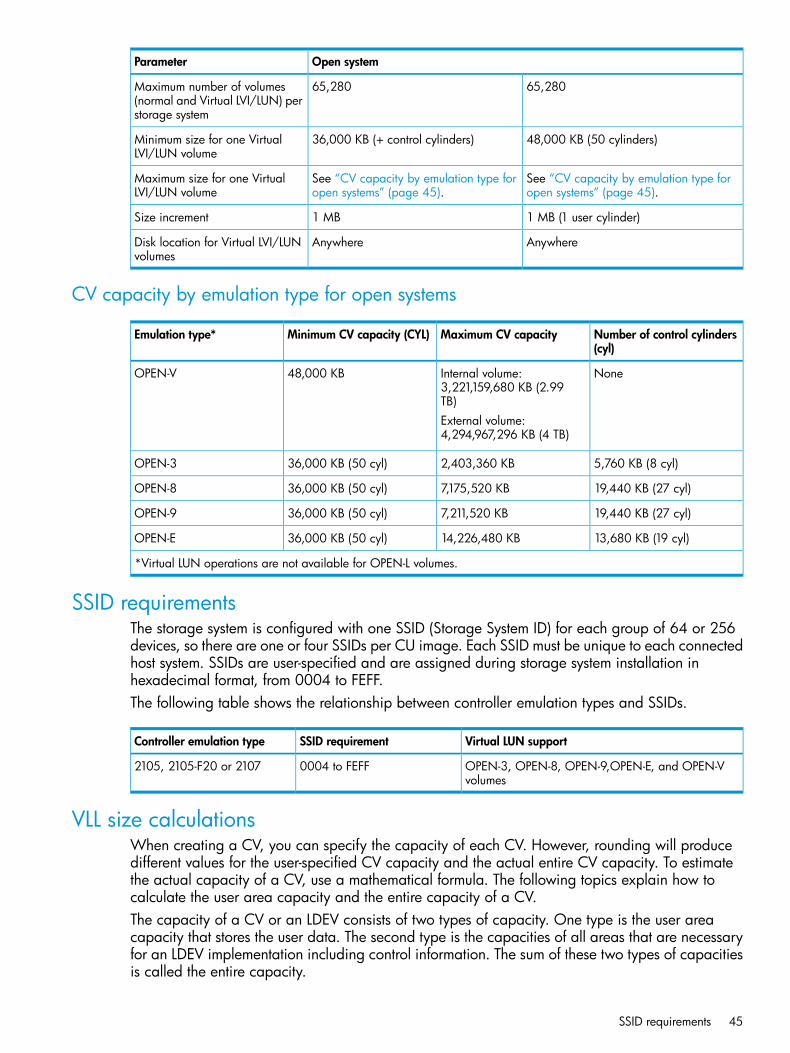
Open systemParameter
65,28065,280Maximum number of volumes(normal and Virtual LVI/LUN) perstorage system
48,000 KB (50 cylinders)36,000 KB (+ control cylinders)Minimum size for one VirtualLVI/LUN volume
See “CV capacity by emulation type foropen systems” (page 45).
See “CV capacity by emulation type foropen systems” (page 45).
Maximum size for one VirtualLVI/LUN volume
1 MB (1 user cylinder)1 MBSize increment
AnywhereAnywhereDisk location for Virtual LVI/LUNvolumes
CV capacity by emulation type for open systems
Number of control cylinders(cyl)
Maximum CV capacityMinimum CV capacity (CYL)Emulation type*
NoneInternal volume:3,221,159,680 KB (2.99TB)
48,000 KBOPEN-V
External volume:4,294,967,296 KB (4 TB)
5,760 KB (8 cyl)2,403,360 KB36,000 KB (50 cyl)OPEN-3
19,440 KB (27 cyl)7,175,520 KB36,000 KB (50 cyl)OPEN-8
19,440 KB (27 cyl)7,211,520 KB36,000 KB (50 cyl)OPEN-9
13,680 KB (19 cyl)14,226,480 KB36,000 KB (50 cyl)OPEN-E
*Virtual LUN operations are not available for OPEN-L volumes.
SSID requirementsThe storage system is configured with one SSID (Storage System ID) for each group of 64 or 256devices, so there are one or four SSIDs per CU image. Each SSID must be unique to each connectedhost system. SSIDs are user-specified and are assigned during storage system installation inhexadecimal format, from 0004 to FEFF.The following table shows the relationship between controller emulation types and SSIDs.
Virtual LUN supportSSID requirementController emulation type
OPEN-3, OPEN-8, OPEN-9,OPEN-E, and OPEN-Vvolumes
0004 to FEFF2105, 2105-F20 or 2107
VLL size calculationsWhen creating a CV, you can specify the capacity of each CV. However, rounding will producedifferent values for the user-specified CV capacity and the actual entire CV capacity. To estimatethe actual capacity of a CV, use a mathematical formula. The following topics explain how tocalculate the user area capacity and the entire capacity of a CV.The capacity of a CV or an LDEV consists of two types of capacity. One type is the user areacapacity that stores the user data. The second type is the capacities of all areas that are necessaryfor an LDEV implementation including control information. The sum of these two types of capacitiesis called the entire capacity.
SSID requirements 45

Implemented LDEVs consume the entire capacity from the parity group capacity. Therefore, evenif the sum of user areas of multiple CVs and the user area of one CV are the same size, theremaining free space generated when multiple CVs are created may be smaller than the free spacein the parity group when one CV is created.Additionally, if the data protection level is set to the Enhanced mode on a SATA drive parity group,you must calculate the entire capacity of all CVs in existence and the entire capacity of CVs in theEnhanced mode of the data protection level.When using RAID Manager, the specified size of CVs is created regardless of the capacitycalculation. Therefore, even if the same capacity size (for example, 1 TB) appears, the actualcapacity size might be different between the CVs created by RAID Manager and the CVs createdby Remote Web Console.
Calculating OPEN-V volume size (CV capacity unit is MB)The methods for calculating the user area capacity and the entire capacity of a CV vary dependingon the CV capacity unit that is specified when creating the CV.To calculate the user area capacity of a CV whose capacity unit is defined as megabytes:ceil(ceil(user-specified-CV-capacity * 1024 / 64) / 15) * 64 * 15
where
• the value enclosed in ceil( ) must be rounded up to the nearest whole number.
• user-specified-CV-capacity is expressed in megabytes.
• The resulting user area capacity is expressed in kilobytes.To calculate the entire capacity of a CV:ceil(user-area-capacity / boundary-value) * boundary-value / 1024
where
• the value enclosed in ceil( ) must be rounded up to the nearest whole number.
• user-area-capacity is expressed in kilobytes
• boundary value is expressed in kilobytes. The boundary value depends on volume emulationtypes and RAID levels (see “Boundary values for RAID levels (other than Enhanced mode onSATA drives)” (page 50)). If the data protection level is set to the Enhanced mode on a SATAdrive, the boundary value depends on volume emulation types and RAID levels (see“Boundary values for RAID levels (Enhanced mode on SATA drives)” (page 50)).
• The resulting entire capacity is expressed in megabytes.
Calculating OPEN-V volume size (CV capacity unit is blocks)To calculate the user area capacity of a CV whose capacity unit is defined as blocks:ceil(user-specified-CV-capacity / 2)
where
• the value enclosed in ceil( ) must be rounded up to the nearest whole number.
• user-specified-CV-capacity is expressed in blocks.
• The resulting user area capacity is expressed in kilobytes.To calculate the entire capacity of a CV:ceil(user-specified-CV-capacity / (boundary-value * 2)) * (boundary-value * 2)
where
• the value enclosed in ceil( ) must be rounded up to the nearest whole number.
• user-specified-CV-capacity is expressed in blocks.
46 Configuring custom-sized provisioning

• boundary-value is expressed in kilobytes. The boundary value depends on volume emulationtypes and RAID levels (see “Boundary values for RAID levels (Enhanced mode on SATA drives)”(page 50)). If the data protection level is set to the Enhanced mode on a SATA drive, theboundary value depends on volume emulation types and RAID levels (see “Capacity of a slot”(page 50))
• The resulting entire capacity is expressed in blocks. To convert the resulting entire capacityinto megabytes, divide this capacity by 2,048.
Calculating fixed-size open-systems volume size (CV capacity unit is MB)To calculate the user area capacity of a CV whose capacity unit is defined as megabytes:ceil(ceil(user-specified-CV-capacity * 1024 / capacity-of-a-slot) / 15) * capacity-of-a-slot * 15
where
• the value enclosed in ceil( ) must be rounded up to the nearest whole number.
• user-specified-CV-capacity is expressed in megabytes.
• capacity-of-a-slot is expressed in kilobytes. The capacity of a slot depends on volumeemulation types (see “Calculated management area capacities (SATA-E drive)” (page 50)).
• The resulting user area capacity is expressed in kilobytes.To calculate the entire capacity of a CV:ceil((user-area-capacity + management-area-capacity) /boundary-value) * boundary-value / 1024
where
• The value enclosed in ceil( ) must be rounded up to the nearest whole number.
• user-area-capacity is expressed in kilobytes.
• management-area-capacity is expressed in kilobytes. The management area capacitydepends on volume emulation types (see “Boundary values for RAID levels (other than Enhancedmode on SATA drives)” (page 50)).
• boundary-value is expressed in kilobytes. The boundary value depends on volume emulationtypes and RAID levels (see “Boundary values for RAID levels (Enhanced mode on SATA drives)”(page 50)). If the data protection level is set to the Enhanced mode on a SATA drive, theboundary value depends on volume emulation types and RAID levels (see “Capacity of a slot”(page 50)).
• The resulting entire capacity is expressed in megabytes.
Calculating fixed-size open-systems volume size (CV capacity unit is blocks)To calculate the user area capacity of a CV whose capacity unit is defined as blocks:user-specified-CV-capacity / 2
where
• user-specified-CV-capacity is expressed in blocks.
• The resulting user area capacity is expressed in kilobytes.To calculate the entire capacity of a CV:ceil((user-specified-CV-capacity + management-area-capacity * 2)/ (boundary-value * 2)) * (boundary-value * 2)
where
• the value enclosed in ceil( ) must be rounded up to the nearest whole number.
• user-specified-CV-capacity is expressed in blocks.
VLL size calculations 47

• management-area-capacity is expressed in kilobytes. The management area capacitydepends on volume emulation types (see “Boundary values for RAID levels (other than Enhancedmode on SATA drives)” (page 50)).
• boundary-value is expressed in kilobytes. The boundary value depends on volume emulationtypes and RAID levels (see “Boundary values for RAID levels (Enhanced mode on SATA drives)”(page 50)). If the data protection level is set to the Enhanced mode on a SATA drive, theboundary value depends on volume emulation types and RAID levels (see “Capacity of aslot” (page 50)).
• The CV capacity recognized by hosts is the same as the CV capacity calculated by the aboveformula.
• If block is selected as the LDEV capacity unit in the Create LDEVs window and dialog boxes,the window and dialog boxes correctly show the calculated LDEV capacity. However, if MB,GB, or TB is selected as the LDEV capacity unit in the Create LDEVs window and dialog boxes,the capacity values shown might have a margin of error due to unit conversion reasons. If youneed to know the exact LDEV capacity, select block as the capacity unit.
• The resulting entire capacity is expressed in blocks. To convert the resulting entire capacityinto megabytes, divide this capacity by 2,048:
Calculating the size of a CV using Enhanced mode on SATA drivesIf the data protection level is set to Enhanced mode on a SATA drive, the entire capacity of a CVmust be calculated based on the previously calculated entire capacity of a CV. The calculationmethods vary depending on the unit for the capacity specified when creating the CV. These arerequired to be OPEN-V.
If the CV capacity unit is MB (megabytes):To calculate the entire capacity of a CV whose capacity unit is defined as MB:entire-capacity-of-a-CV * 1024 / capacity-of-a-slot
where
• capacity-of-a-slot is expressed in kilobytes. The capacity of a slot depends on volumeemulation types (see “Capacity of a slot” (page 50)).
• The resulting entire capacity is expressed in slots.To calculate the management area capacity:ceil(entire-capacity-of-a-CV(slots) / calculated-management-area-capacity) * boundary-value
where
• the value enclosed in ceil( ) must be rounded up to the nearest whole number.
• calculated-management-area-capacity depends on volume emulation types andRAID levels (see “Management area capacity of an open-systems volume” (page 49)).
• The resulting entire capacity is expressed in slots.To calculate the entire capacity of a CV if the data protection level is set to the Enhanced modeon the SATA drive:ceil(entire-capacity-of-a-CV(slots) + calculated-management-area-capacity)
To convert the resulting entire capacity into megabytes:calculated-entire-capacity-of-a-CV(slots) /1024 * capacity-of-a-slot
48 Configuring custom-sized provisioning

where
• calculated-entire-capacity-of-a-CV(slots) means the entire capacity of a CVif the data protection level is set to the Enhanced mode on the SATA drive.
If the CV capacity unit is block:To calculate the entire capacity of a CV whose capacity unit is defined as block:user-specified-a-CV-capacity / 2 / capacity-of-a-slot
where
• capacity-of-a-slot is expressed in kilobytes. The capacity of a slot depends on volumeemulation types (see “Capacity of a slot” (page 50)).
• The resulting entire capacity is expressed in slots.To calculate the management area capacity:ceil(entire-capacity-of-a-CV(slots) /calculated-management-area-capacity) * boundary-value
where
• the value enclosed in ceil( ) must be rounded up to the nearest whole number.
• calculated-management-area-capacity depends on volume emulation types andRAID levels (see “Management area capacity of an open-systems volume” (page 49)).
To calculate the entire capacity of a CV if the data protection level is set to the Enhanced modeon the SATA drive:ceil(entire-capacity-of-a-CV(slots) + calculated-management-area-capacity)
To convert the resulting entire capacity into blocks:calculated-entire-capacity-of-a-CV(slots) * capacity-of-a-slot * 2
where
• calculated-entire-capacity-of-a-CV(slots) means the entire capacity of a CVif the data protection level is set to the Enhanced mode on the SATA drive.
Management area capacity of an open-systems volume
Management area capacity (KB)Emulation type
NoneOPEN-V
5,760OPEN-3
19,440OPEN-8
19,440OPEN-9
13,680OPEN-E
VLL size calculations 49

Boundary values for RAID levels (Enhanced mode on SATA drives)A SATA drive supports the OPEN-V emulation type for an open system.
Boundary value (KB)Emulation type
RAID 6 (14D+2P)RAID 6 (6D+2P)RAID 5 (7D+1P)RAID 5 (3D+1P)RAID 1 (2D+2D)
114,68824,57628,6726,1442,048OPEN-V
Notes:• xx indicates one or more numbers or letters.
• Boundary values are expressed in kilobytes.
• A SATA drive supports the OPEN-V emulation type for open systems.
Boundary values for RAID levels (other than Enhanced mode on SATA drives)Boundary values of external volumes are always one slot, regardless of RAID levels.
Boundary value (KB)Emulation type*
RAID 6(14D+2P)
RAID 6 (6D+2P)RAID 5 (7D+1P)RAID 5 (3D+1P)RAID 1 (2D+2D)
-2,3042,6881,152768OPEN-xx (except forOPEN-V)
7,1683,0723,5841,5361,024OPEN-V
Notes:• xx indicates one or more numbers or letters.
• Boundary values are expressed in kilobytes.
• Boundary values of external volumes are always one kilobyte, regardless of RAID levels.
• Hyphen (-) indicates that the combination is not supported.
Capacity of a slot
Capacity (KB) of a slotEmulation type
48OPEN-xx (except for OPEN-V)
256OPEN-V
Notes:• xx indicates one or more numbers or letters.
• Slot capacity is expressed in kilobytes.
Calculated management area capacities (SATA-E drive)
SATA-E (slots)Emulation type
RAID 6 (14D+2P)RAID 6 (6D+2P)RAID 5 (7D+1P)RAID 5 (3D+1P)RAID 1 (2D+2D)
12,042,2402,211,8403,010,560552,960122,880OPEN-V
Notes:• xx indicates one or more numbers or letters.
• Calculated management area capacities are expressed in slots.
• A SATA drive supports the OPEN-V emulation type for a open systems.
50 Configuring custom-sized provisioning
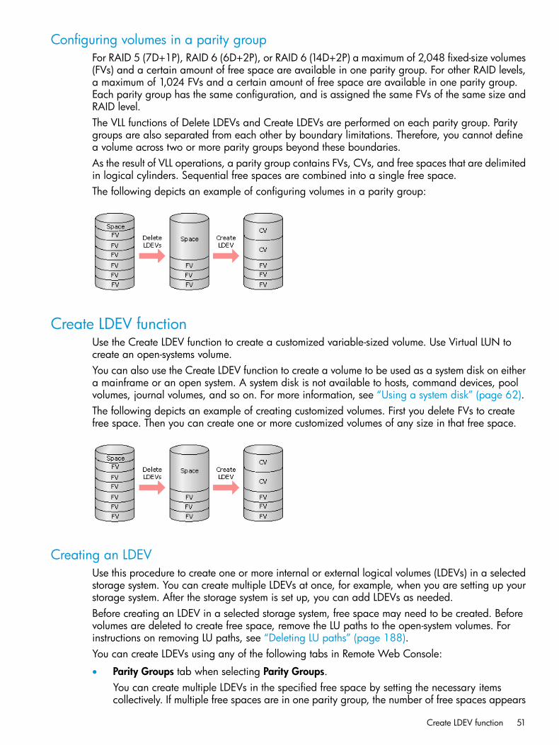
Configuring volumes in a parity groupFor RAID 5 (7D+1P), RAID 6 (6D+2P), or RAID 6 (14D+2P) a maximum of 2,048 fixed-size volumes(FVs) and a certain amount of free space are available in one parity group. For other RAID levels,a maximum of 1,024 FVs and a certain amount of free space are available in one parity group.Each parity group has the same configuration, and is assigned the same FVs of the same size andRAID level.The VLL functions of Delete LDEVs and Create LDEVs are performed on each parity group. Paritygroups are also separated from each other by boundary limitations. Therefore, you cannot definea volume across two or more parity groups beyond these boundaries.As the result of VLL operations, a parity group contains FVs, CVs, and free spaces that are delimitedin logical cylinders. Sequential free spaces are combined into a single free space.The following depicts an example of configuring volumes in a parity group:
Create LDEV functionUse the Create LDEV function to create a customized variable-sized volume. Use Virtual LUN tocreate an open-systems volume.You can also use the Create LDEV function to create a volume to be used as a system disk on eithera mainframe or an open system. A system disk is not available to hosts, command devices, poolvolumes, journal volumes, and so on. For more information, see “Using a system disk” (page 62).The following depicts an example of creating customized volumes. First you delete FVs to createfree space. Then you can create one or more customized volumes of any size in that free space.
Creating an LDEVUse this procedure to create one or more internal or external logical volumes (LDEVs) in a selectedstorage system. You can create multiple LDEVs at once, for example, when you are setting up yourstorage system. After the storage system is set up, you can add LDEVs as needed.Before creating an LDEV in a selected storage system, free space may need to be created. Beforevolumes are deleted to create free space, remove the LU paths to the open-system volumes. Forinstructions on removing LU paths, see “Deleting LU paths” (page 188).You can create LDEVs using any of the following tabs in Remote Web Console:
• Parity Groups tab when selecting Parity Groups.You can create multiple LDEVs in the specified free space by setting the necessary itemscollectively. If multiple free spaces are in one parity group, the number of free spaces appears
Create LDEV function 51

in Total Selected Free Space in the Parity Group Selection section on the Create LDEVs wizard.Confirm the number of free spaces, and then create the LDEVs accordingly.For example, if you are creating LDEVs in parity group PG1-1 and it contains two free spaces,2 appears in Total Selected Free Space. In this case, if you specify 1 in Number of LDEVs perFree Space, and continue to create the LDEV, two LDEVs are created because one LDEV iscreated for each free space.
• LDEVs tab when selecting any parity group in Parity Groups.
• LDEVs tab when selecting Logical Devices.Procedure 6 To create an LDEV1. In the Remote Web Console main window, in the Storage Systems tree, select the resource to
view in the tab, and then click Create LDEVs.2. In the Create LDEVs window, from the Provisioning Type list, select a provisioning type for the
LDEV to be created.• If creating internal volumes, select Basic.
• If creating external volumes, select External.3. In System Type, select Open to create open system volumes.4. From the Emulation Type list, select an emulation type for the selected system type.5. If creating an internal volume, select the parity group, and then do the following:
1. From the Drive Type/RPM list in Parity Group Selection, select the drive type and RPM.2. From the RAID level list in Parity Group Selection, select the RAID level.3. Click Select Free Spaces.4. In the Select Free Spaces window, in the Available Free Spaces table, select the free spaces
to be assigned to the volumes.Do the following, if necessary:- To specify the conditions and show the free space, click Filter, specify the conditions,and then click Apply.- To specify the unit for capacity and the number of rows to view, click Options.
5. Click View Physical Location.6. In the View Physical Location window, confirm where the selected free space is physically
located, and then click Close.7. In the Select Free Spaces window, if the selected free spaces have no issues, click OK.
6. Otherwise, if creating an external volume, select the external volume, and then do the following:1. Click Select Free Spaces.2. In the Select Free Spaces window, in the Available Free Spaces table, select the free space
to be assigned to the volumes.Do the following, if necessary:- To specify the conditions and show the free space, click Filter, specify the conditions,and then click Apply.- To specify the unit for capacity and the number of rows to view, click Options.
3. Click View Physical Location.4. In the View Physical Location window, confirm where the selected free space is physically
located, and then click Close.5. In the Select Free Spaces window, if the selected free spaces have no issues, click OK.
52 Configuring custom-sized provisioning

7. In LDEV Capacity, type the amount of LDEV capacity to be created and select a capacity unitfrom the list.You can enter the capacity within the range of figures displayed below the text box. You canenter the number with 2 digits after decimal point. You can change the capacity unit from thelist.
8. In Number of LDEVs, type the number of LDEVs to be created.• For an internal volume, Number of LDEVs per Free Space appears.
• For an external volume, Number of LDEVs per External Volume appears.9. In LDEV Name, specify a name for this LDEV.
1. In Prefix, type the characters that will become the fixed characters for the beginning ofthe LDEV name. The characters are case-sensitive.
2. In Initial Number, type the initial number that will follow the prefix name.10. In Format Type, select the format type for the LDEV from the list.
• For an internal volume, you can select Normal Format, Quick Format, or No Format.If No Format is selected, format the volume after creating LDEVs.
• For an external volume, if you create the LDEV whose emulation type is the open system,you can select Normal Format or No Format.If the external volume can be used as it is, select No Format. The created LDEV can beused without formatting.If the external volume needs to be formatted, select No Format and then format the volumewith the external storage system, or select Normal Format.
• If you select Quick Format, host I/Os might be affected when you perform the QuickFormat operation. For details, see (page 58).
11. Click Options to show more options.12. In Initial LDEV ID, make sure that an LDEV ID is set. To confirm the used number and unavailable
number, click View LDEV IDs to open the View LDEV IDs window.1. In Initial LDEV ID in the Create LDEVs window, click View LDEV IDs.
In the View LDEV IDs window, the matrix vertical scale represents the second-to-last digitof the LDEV number, and the horizontal scale represents the last digit of the LDEV number.The LDEV IDs table shows the available, used, and disabled LDEV IDs.In the table, used LDEV numbers appear in blue, unavailable numbers appear in gray,and unused numbers appear in white. LDEV numbers that are unavailable may be alreadyin use, or already assigned to another emulation group (group by 32 LDEV numbers).
2. Click Close.13. In the Create LDEVs window, in SSID, type four digits, in hexadecimal format (0004 to FEFF),
for the SSID.14. To confirm the created SSID, click View SSIDs to open the View SSIDs dialog box.
1. In the Create LDEVs window, in Initial SSID, click View SSIDs.In the SSIDs window, the SSIDs table shows the used SSIDs.
2. Click Close.15. In the Create LDEVs window, from the Processor Blade list, select a processor blade to be used
by the LDEVs.• If you assign a specific processor blade, select the ID of the processor blade.
• If you can assign any processor blade, click Auto.16. If you are creating one more system disks, select Create LDEVs as System Disk.
Create LDEV function 53
17. Click Add.The created LDEVs are added to the Selected LDEVs table.The Provisioning Type, System Type, Emulation Type, Parity Group Selection, LDEV Capacity,and Number of LDEVs per Free Space or the Number of LDEVs per External Volume fields mustbe set. If these required items are not registered, you cannot click Add.
18. If necessary, change the following LDEV settings:• Click Edit SSIDs to open the SSIDs window. If a new LDEV is to be created in the CU, you
can change the SSID to be allocated to the LDEV. For details about how to edit an SSID,see “Editing an LDEV SSID ” (page 54).
• Click Change LDEV Settings to open the Change LDEV Settings window. For details abouthow to change the LDEV settings, see “Changing LDEV settings” (page 55).
19. If necessary, delete an LDEV from the Selected LDEVs table.Select an LDEV to delete, and then click Remove. For details about how to remove an LDEV,see “Removing an LDEV to be registered” (page 55).
20. Click Finish.The Confirm window opens.To continue the operation for setting the LU path and defining a logical unit, click Next. Fordetails about how to set the LU path, see “Defining LU paths” (page 185).
21. In the Confirm window, confirm the settings, in Task Name type a unique name for this taskor accept the default, and then click Apply.If Go to tasks window for status is checked, the Tasks window opens.
Finding an LDEV IDWhen creating volumes, the LDEV ID (LDKC: CU: LDEV) must be specified. Use this procedure todetermine the LDEV IDs in use in the storage system so you can specify the correct LDEV.1. In Initial LDEV ID in the Create LDEVs window, click View LDEV IDs.2. In the View LDEV IDs window, review the list to confirm the LDEV IDs. The LDEV IDs table shows
the available, used, and disabled LDEV IDs.The matrix vertical scale represents the second-to-last digit of the LDEV number, and thehorizontal scale represents the last digit of the LDEV number.In the table, used LDEV numbers appear in blue, unavailable LDEV numbers appear in gray,and unused LDEV IDs appear in white. LDEV numbers that are unavailable may be alreadyin use, or already assigned to another emulation group (group by 32 LDEV numbers).
3. Click Close.The Create LDEVs window opens.
Finding an LDEV SSIDWhen creating volumes, the LDEV SSIDs must be specified. Use this procedure to determine theSSIDs in use in the storage system so you can specify the correct SSID.1. In the Create LDEVs window, beside Initial SSID, click View SSIDs.2. In the SSIDs window, review the list to confirm the LDEV SSIDs. The SSIDs table shows the
SSIDs in use in the system.3. Click Close. The Create LDEVs window opens.
Editing an LDEV SSIDBefore registering an LDEV, you may need to edit the LDEV SSID. If a CU is specified in which thefirst LDEV is created, the specified value of the SSID can be changed.
54 Configuring custom-sized provisioning
1. In the Create LDEVs window, in the Selected LDEVs table, click Edit SSIDs.2. In the Edit SSIDs window, review the SSIDs table showing the existing SSIDs and ones to be
added.3. If you change the SSID, select the appropriate LDEV, and then click Change SSIDs.4. In the Change SSIDs window, type the new SSID, and then click OK.5. In the Edit SSIDs window, click OK.6. In the Create LDEVs window, click Finish.7. In the Confirm window, click Apply.
The new SSID is registered.If Go to tasks window for status is checked, the Tasks window opens.
Changing LDEV settingsBefore registering an LDEV, you may need to change the LDEV settings.1. In the Create LDEVs window, in the Selected LDEVs table, select an LDEV, and then click Change
LDEV Settings.2. In the Change LDEV Settings window, you can change the setting of LDEV Name, Initial LDEV
ID, or Processor Blade.• If you change LDEV Name, specify the prefix characters and the initial number for this
LDEV.• If you change Initial LDEV ID, specify the number of LDKC, CU, DEV, and Interval. To
confirm used LDEV IDs, click View LDEV IDs to confirm the used LDEV IDs in the ViewLDEV IDs window.
• If you change Processor Blade, click the list and specify the processor blade ID. If thespecific processor blade is specified, select the processor blade ID. If any processor bladeis specified, click Auto.
3. Click OK.4. In the Create LDEVs window, click Finish.5. In the Confirm window, verify the settings, and then click Apply.
The settings are changed.If Go to tasks window for status is checked, the Tasks window opens.
Removing an LDEV to be registeredIf you do not want to register an LDEV that is scheduled to be registered, you can remove it fromthe registering task.1. In the Selected LDEVs table in the Create LDEVs window, select an LDEV, and then click Remove.
A message appears asking whether you want to remove the selected row or rows. If you wantto remove the row, click OK.
2. Click Finish.3. In the Confirm window, click Apply. The LDEV is removed from the registering task.
If Go to tasks window for status is checked, the Tasks window opens.
Blocking an LDEVBefore formatting or shredding a registered LDEV, the LDEV must be blocked. This procedure blocksboth internal and external volumes.
Blocking an LDEV 55

You can block LDEVs from any of the following tabs:
• LDEVs tab when selecting any parity group in Parity Groups.
• LDEVs tab when selecting Logical Devices.
• Virtual Volumes tab when selecting any pool in Pool.1. In the Remote Web Console main window, in the Storage Systems tree, select the resource to
view in the tab.2. Find the target LDEV in the table and confirm the LDEV status in the Status column.
• If Blocked appears, the LDEV is blocked. You can skip the remaining steps.
• If Blocked does not appear, the LDEV is not blocked. Block the LDEV using the followingsteps.
3. Select an LDEV, click More Actions, and select Block LDEVs.You can select multiple LDEVs that are listed together or separately. For LDEVs that are listedtogether, select them while pressing the Shift key. For LDEVs that are listed separately, clickeach while pressing the Ctrl key.
4. In the Confirm window, confirm the settings, in Task Name type a unique name for this taskor accept the default, and then click Apply.If Go to tasks window for status is checked, the Tasks window opens.
Restoring a blocked LDEVYou can restore a blocked LDEV using any of the following tabs:
• LDEVs tab when selecting any parity group in Parity Groups.
• LDEVs tab when selecting Logical Devices.
• Virtual Volumes tab when selecting any pool in Pool.1. In the Remote Web Console main window, in the Storage Systems tree, select the resource to
view in the tab.2. Find the target LDEV in the table and confirm the LDEV status in the Status column.
• If Blocked appears, the LDEV is blocked. Restore a blocked LDEV using the followingsteps.
• If Blocked does not appear, the LDEV is not blocked.3. Select the blocked LDEV, click More Actions, and select Restore.
You can select multiple LDEVs that are listed together or separately. For LDEVs that are listedtogether, select them while pressing the Shift key. For LDEVs that are listed separately, clickeach while pressing the Ctrl key.
4. In the Confirm window, confirm the settings, in Task Name type a unique name for this taskor accept the default, and then click Apply.If Go to tasks window for status is checked, the Tasks window opens.
Editing an LDEV nameYou can edit the name of a registered internal volume.For information about editing a registered external volume, see the HP XP P9000 External Storagefor Open and Mainframe Systems User Guide.1. Select the LDEV to be edited.2. Click Edit LDEVs.3. In Edit LDEVs window, edit LDEV Name.4. Click Finish.
56 Configuring custom-sized provisioning
5. In the Confirm window, confirm the settings, in Task Name type a unique name for this taskor accept the default, and then click Apply.If Go to tasks window for status is checked, the Tasks window opens.
Deleting an LDEV (converting to free space)You can convert one or more of the LDEVs on a selected parity group into free space by deletingthe LDEVs. That free space can be used to either create one or more variable-sized volumes (CVs)using the Create LDEVs function, or left as free space for future use. You can also delete a systemdisk if you no longer need it.
WARNING! Deleting LDEVs will erase your data. Back up your data before deleting LDEVs.
An LDEV cannot be deleted successfully if it is:
• In the defined path (including the pair volumes of Continuous Access Synchronous andContinuous Access Journal).
• A configuration element of LUSE.
• A reserved volume of Auto LUN.
• A pool-VOL (including LUSE).
• A journal volume.
• A remote command device.
• A volume security volume.
• A quorum disk.
• An LDEV that has the Read/Write access attribute.
• Online data migration volume.
• An LDEV with the Volume Security for Mainframe setting.When you delete an LDEV, the alias information contained in the LDEV is also deleted. Therefore,if you delete an LDEV related to an alias device, you should do one of the following:
• Allocate another LDEV to the alias device, and then delete the LDEV.
• Delete the LDEV first, and then allocate another LDEV to the alias device.For information about how to delete a registered external volume, see the HP XP P9000 ExternalStorage for Open and Mainframe Systems User Guide.Procedure 7 To delete an LDEV1. Select one or more LDEVs to be deleted.2. Click More Actions and select Delete LDEVs.3. In the Confirm window, confirm the settings, in Task Name type a unique name for this task
or accept the default, and then click Apply.The LDEV is deleted.If Go to tasks window for status is checked, the Tasks window opens.
Formatting LDEVsIf you initialize LDEVs that are being used, you will need to format the LDEVs. Read the followingtopics before formatting LDEVs:
• “About formatting LDEVs” (page 58)
• “Storage system operation when LDEVs are formatted” (page 58)
• “Quick Format function” (page 58)
Deleting an LDEV (converting to free space) 57

Formatting LDEVs includes the following tasks:
• “Formatting a specific LDEV” (page 60)
• “Formatting all LDEVs in a parity group” (page 60)
About formatting LDEVsThe LDEV Format function, which includes Normal Format, and Quick Format. These functionsformat volumes, including external volumes. Before formatting volumes, ensure that the volumesare in blocked status.The following table lists which formatting functions can be used on which LDEV types.
Corresponding volumeFormatting function
Internal volumeNormal FormatVirtual volumeExternal volume
Internal volumeQuick Format
Storage system operation when LDEVs are formattedThe storage system acts in one of two ways immediately after an LDEV is added, depending onthe default settings in the storage system.
• The storage system automatically formats the added LDEV. This is the default action.
• The storage system blocks the LDEV instead of automatically formatting it.To confirm or change the default formatting settings on the storage system, contact the administrator.Users who have the Storage Administrator (Provisioning) role can change these default formattingsettings using Remote Web Console.
Quick Format functionThe Quick Format function formats internal volumes in the background. While Quick Format isrunning in the background, you can configure your system before the formatting is completed.Before using Quick Format to format internal volumes, ensure that the internal volumes are inblocked status.I/O operations from a host during Quick Format are allowed. Formatting in the background mightaffect performance.Quick Format cannot be performed on the following volumes:
• Any volumes other than internal volumes
• Volumes assigned an access attribute other than read/write
• Pool volumes
• Journal volumes
• Quorum disksBecause shared resources such as MP blades or cache paths are used during quick formatoperations, all host I/Os in a storage system may be affected.
58 Configuring custom-sized provisioning
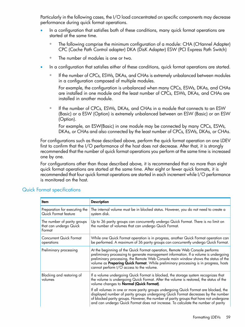
Particularly in the following cases, the I/O load concentrated on specific components may decreaseperformance during quick format operations.
• In a configuration that satisfies both of these conditions, many quick format operations arestarted at the same time.
◦ The following comprise the minimum configuration of a module: CHA (CHannel Adapter)CPC (Cache Path Control adapter) DKA (DisK Adapter) ESW (PCI Express Path Switch)
◦ The number of modules is one or two.
• In a configuration that satisfies either of these conditions, quick format operations are started.
If the number of CPCs, ESWs, DKAs, and CHAs is extremely unbalanced between modulesin a configuration composed of multiple modules.For example, the configuration is unbalanced when many CPCs, ESWs, DKAs, and CHAsare installed in one module and the least number of CPCs, ESWs, DKAs, and CHAs areinstalled in another module.
◦
◦ If the number of CPCs, ESWs, DKAs, and CHAs in a module that connects to an ESW(Basic) or a ESW (Option) is extremely unbalanced between an ESW (Basic) or an ESW(Option).For example, an ESW(Basic) in one module may be connected by many CPCs, ESWs,DKAs, or CHAs and also connected by the least number of CPCs, ESWs, DKAs, or CHAs.
For configurations such as those described above, perform the quick format operation on one LDEVfirst to confirm that the I/O performance of the host does not decrease. After that, it is stronglyrecommended that the number of quick format operations you perform at the same time is increasedone by one.For configurations other than those described above, it is recommended that no more than eightquick format operations are started at the same time. After eight or fewer quick formats, it isrecommended that four quick format operations are started in each increment while I/O performanceis monitored on the host.
Quick Format specifications
DescriptionItem
The internal volume must be in blocked status. However, you do not need to create asystem disk.
Preparation for executing theQuick Format feature
Up to 36 parity groups can concurrently undergo Quick Format. There is no limit onthe number of volumes that can undergo Quick Format.
The number of parity groupsthat can undergo QuickFormat
While one Quick Format operation is in progress, another Quick Format operation canbe performed. A maximum of 36 parity groups can concurrently undergo Quick Format.
Concurrent Quick Formatoperations
At the beginning of the Quick Format operation, Remote Web Console performspreliminary processing to generate management information. If a volume is undergoing
Preliminary processing
preliminary processing, the Remote Web Console main window shows the status of thevolume as Preparing Quick Format. While preliminary processing is in progress, hostscannot perform I/O access to the volume.
If a volume undergoing Quick Format is blocked, the storage system recognizes thatthe volume is undergoing Quick Format. After the volume is restored, the status of thevolume changes to Normal (Quick Format).
Blocking and restoring ofvolumes
If all volumes in one or more parity groups undergoing Quick Format are blocked, thedisplayed number of parity groups undergoing Quick Format decreases by the numberof blocked parity groups. However, the number of parity groups that have not undergoneand can undergo Quick Format does not increase. To calculate the number of parity
Formatting LDEVs 59

DescriptionItem
groups that have not undergone but can undergo Quick Format, use the followingformula:36 - X - YWhere:X indicates the number of parity groups on which Quick Format is being performed.Y indicates the number of parity groups where all volumes are blocked during the QuickFormat.
The Quick Format operation resumes when power is turned back on.Storage system is powered offand back on
Restrictions • Quick Format cannot be executed on external volumes, virtual volumes, system disks,the journal volumes of Continuous Access Journal and quorum disks.
• The volume migration feature or the QuickRestore feature cannot be applied tovolumes undergoing Quick Format. When you use RAID Manager to execute thevolume migration operation or the QuickRestore operation on volumes undergoingQuick Format, EX_CMDRJE will be reported to RAID Manager. In this case, checkthe volume status with Remote Web Console.
• The prestaging feature of Cache Residency cannot be applied to volumes undergoingQuick Format.
Formatting a specific LDEVThis procedure performs Normal formatting on the volume.1. Select and block the LDEV to be formatted.
See “Blocking an LDEV” (page 55) for blocking an internal volume. See the HP XP P9000External Storage for Open and Mainframe Systems User Guide for blocking an externalvolume.
2. To open the Format LDEVs window, click More Actions, then Format LDEVs from one of thesetabs:• LDEVs tab, selected from the Logical Devices node of the Storage Systems tree.
• Virtual Volumes tab, selected from a pool in the Pools node of the Storage Systems tree.3. In the Format LDEVs window, select the format type from the Format Type list, and then click
Finish.4. In the Confirm window, click Apply.
If Go to tasks window for status is checked, the Tasks window opens.
Formatting all LDEVs in a parity groupThis procedure performs Normal formatting on the volume.When formatting all LDEVs in a parity group, you will need to:
• Specify a parity group.
• Format the LDEV.Before formatting all LDEVs in a parity group, make sure that all LDEVs under this parity grouphave been blocked.See “Blocking an LDEV” (page 55) for blocking an internal volume. See the HP XP P9000 ExternalStorage for Open and Mainframe Systems User Guide for blocking an external volume.1. Select the parity group containing the LDEV to be formatted.2. Click Format LDEVs.
60 Configuring custom-sized provisioning
3. In the Format LDEVs window, select the format type from the Format Type list, and then clickFinish.In the Confirm window, click Next to go to the next operation.
4. Click Apply.If Go to tasks window for status is checked, the Tasks window opens.
Assigning a processor blade
Assigning a processor blade to a resourceYou can assign a processor blade to resources (logical devices, external volumes, and journalvolumes).1. In the Remote Web Console main window, in the Storage Systems tree, select Components.2. In Components, select the name of the DKC for which you want to assign a processor blade.
Processor blades can be viewed in the Processor Blades tab.3. Select a processor blade for which you want to change the settings, and then click Edit MP
Blades.4. In the Edit Processor Blades window, disable or enable Auto Assignment.
• Select Enable if the processor blade can be automatically assigned. This is the default.
• Select Disable if the processor blade cannot be automatically assigned.5. Click Finish.6. In the Confirm window, confirm the settings, in Task Name type a unique name for this task
or accept the default, and then click Apply.If Go to tasks window for status is checked, the Tasks window opens.
Changing the processor blade assigned to an LDEV1. In the Remote Web Console main window, in the Storage Systems tree, select Logical Devices.
LDEVs are shown in the LDEVs tab.2. Select the LDEV for which you want to change the processor blade.3. Click More Actions, and then select Assign MP Blade.4. In the Assign Processor Blade window, specify the processor blade in Processor Blade.5. Click Finish.6. In the Confirm window, confirm the settings, in Task Name type a unique name for this task
or accept the default, and then click Apply.If Go to tasks window for status is checked, the Tasks window opens.
Assigning a processor blade 61

CAUTION:• Changes to the processor blade ID of an LDEV should be made during off-peak hours when
the I/O load is as low as possible. Before and after changes are made, it is recommendedthat the cache write-pending rate (%) for all CLPRs is lower than 50%. Do not change theprocessor blade ID when the I/O load is high -- for example during an initial copy operationof Business Copy, Continuous Access Synchronous, or Continuous Access Journal.
• When you change the processor blade ID of an LDEV, you should use Performance Monitorbefore and after the change to check the load status of devices. Do not change several LDEVprocessor blade IDs during a short period of time. As a guideline, you can change 10% orless of the total number or the full workload of LDEV processor blade IDs assigned to the sameprocessor blade ID at the same time.
• After you change the processor blade ID of an LDEV, wait more than 30 minutes before youtry to change the ID again for the same LDEV.
Using a system diskA system disk is a special LDEV used in the storage system for specific purposes. A system disk isnot required in a storage system, but is recommended for buffering of the audit log. A system diskshould not be used for storing user data. After a system disk is created, the system knows whattypes of information the system disk is used for and all appropriate information is automaticallysent to the system disk.For example, when the system disk is used as an audit log buffer, you set parameters to enablethe audit log buffer. The Audit Log feature recognizes the LDEV number of the system disk and thenaccesses it as a buffer. The system disk must have sufficient capacity to accommodate the auditlog buffer. See the HP XP P9000 Audit Log User and Reference Guide for more information abouthow to enable the audit log buffer.To designate the system disk as the buffer area for audit logs, do one of the following:
• In the Audit Log Setting window, set Audit Log buffer to Enable.
• Set system option mode (SOM) 676 to ON.You can create a system disk on either a mainframe or an open system. To create a system disk,you create an LDEV and then designate it as a system disk in the Create LDEVs wizard (see “Creatingan LDEV” (page 51)). The system disk designation prevents other storage system structures fromaccessing it. It is not available to hosts, or a command device, pool volume, journal, and so on.The system disk is part of one parity group. When an LDEV is defined as a system disk, the LDEVcannot be allocated to a port.The buffering area capacity for the audit log buffer is: 130 MB. Therefore, before using the auditlog, make sure to prepare the system disk to have at minimum the above mentioned free capacityin the volume. The size of the system disk could be 1 GB if you want some spare capacity, or aslarge as 15 GB to accommodate the amount of system information that could be stored on it.If you find you do not need a system disk, you can delete the system disk and convert the volumeto free space (see “Deleting an LDEV (converting to free space)” (page 57)).
62 Configuring custom-sized provisioning

System disk rules, restrictions, and guidelines
Rules
• The minimum size of the system disk should be 130 MB in order to accommodate audit logbuffer information.
• The LDKC:CU:LDEV number assigned to the system disk should be distinguishable from theone for a normal volume.
• Use the Delete LDEVs function to delete the system disk.
Restrictions
• The system disk cannot be created on a THP-VOL.
• A system disk cannot be used for any other function or connected to a port.
• Normal data cannot be stored on the system disk.
• The bind mode of Cache Residency must not be set to the system disk.
• I/O cannot be issued from the host of the open system because the system disk cannot bedefined SCSI path.
• The system disk should not be deleted or blocked while it is being used. Delete or block thesystem disk when it is not being used.
Guidelines
• Although the system disk can be created in an external volume, it is best to use only internalvolumes.
• Although there can be up to 16 volumes of system disks created throughout the entire storagesystem, best practice is to have only one system disk per storage system.
• In a mixed configuration of open and mainframe system volumes in a storage system, it isbest to select open volumes for the system disk.
• If you have more than one system disk on your storage system, and one of them is blocked,the unblocked system disks may not be usable. In this case, delete the blocked system disk,and then use the other normal system disks.
Using a system disk 63
4 Configuring expanded LU provisioningConfiguring expanded LU provisioning involves combining several smaller LDEVs into an expandedlogical unit volume to make a LUSE (logical unit size expansion) volume that is larger than thestandard 2.8 TB. A LUSE volume is a set of LDEVs defined to one or more hosts as a single datastorage unit. A LUSE volume is a concatenation of two to 36 LDEVs (up to 60-TB limit) that arepresented to a host as a single LU.This provisioning strategy is for use on open systems. LUN Expansion software is required to usethe LUSE feature to configure expanded LU provisioning.
About LUSEThe LUSE feature is for open-system logical volumes and allows you to configure one large logicalvolume by combining several smaller LDEVs. To use this feature, you need the software calledOpen Volume Management, which includes LUN Expansion software.The LUSE feature allows hosts that can use only a limited number of LUs per fibre interface to haveaccess to larger amounts of data by using expanded LUs. To create an open-systems volume (LU)larger than 2.8 TB, you must use the LUSE feature to combine open-systems volumes.Up to 36 LDEVs can be combined to create one large logical volume, called a LUSE volume. TheID of the logical volume defined as the large logical volume is represented by the smallest LDEVID (assigned to the top LDEV). The host recognizes the expanded logical volume as onerepresentative LDEV. As long as the number of LDEVs combined into one large logical volume doesnot exceed 36, you can arbitrarily select any LDEVs as the volumes to combine, regardless of theirsize (or capacity) or whether they are on the same control unit (CU).Using the LUSE feature, you can also combine several LDEVs and a LUSE volume (combined LDEVs)into one LUSE volume, or combine LUSE volumes together into one LUSE volume. The host alsorecognizes this type of LUSE volume as one LDEV.The host cannot access the individual LDEVs or LUSE volumes that make up an expanded LU (LUSEvolume). If you want to access the individual volumes, you must release the expanded LU.For information about the maximum LU capacity supported by your operating system, contact thevendor of your operating system.
LUN Expansion license requirementsUse of LUN Expansion on the P9500 storage system requires license key on the Remote WebConsole computer for Open Volume Management software. For details about the license key orproduct installation, see the HP XP P9000 Remote Web Console User Guide.
LUSE configuration exampleThe following figure shows an example of a LUSE configuration. The host sees the LUSE volumeas one LDEV. The LUSE volume ID is the smallest LDEV ID.
64 Configuring expanded LU provisioning
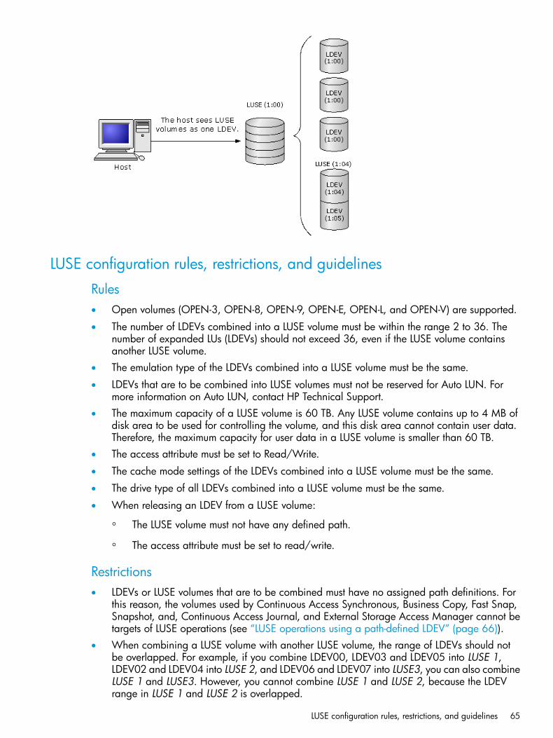
LUSE configuration rules, restrictions, and guidelines
Rules• Open volumes (OPEN-3, OPEN-8, OPEN-9, OPEN-E, OPEN-L, and OPEN-V) are supported.
• The number of LDEVs combined into a LUSE volume must be within the range 2 to 36. Thenumber of expanded LUs (LDEVs) should not exceed 36, even if the LUSE volume containsanother LUSE volume.
• The emulation type of the LDEVs combined into a LUSE volume must be the same.
• LDEVs that are to be combined into LUSE volumes must not be reserved for Auto LUN. Formore information on Auto LUN, contact HP Technical Support.
• The maximum capacity of a LUSE volume is 60 TB. Any LUSE volume contains up to 4 MB ofdisk area to be used for controlling the volume, and this disk area cannot contain user data.Therefore, the maximum capacity for user data in a LUSE volume is smaller than 60 TB.
• The access attribute must be set to Read/Write.
• The cache mode settings of the LDEVs combined into a LUSE volume must be the same.
• The drive type of all LDEVs combined into a LUSE volume must be the same.
• When releasing an LDEV from a LUSE volume:
The LUSE volume must not have any defined path.◦◦ The access attribute must be set to read/write.
Restrictions• LDEVs or LUSE volumes that are to be combined must have no assigned path definitions. For
this reason, the volumes used by Continuous Access Synchronous, Business Copy, Fast Snap,Snapshot, and, Continuous Access Journal, and External Storage Access Manager cannot betargets of LUSE operations (see “LUSE operations using a path-defined LDEV” (page 66)).
• When combining a LUSE volume with another LUSE volume, the range of LDEVs should notbe overlapped. For example, if you combine LDEV00, LDEV03 and LDEV05 into LUSE 1,LDEV02 and LDEV04 into LUSE 2, and LDEV06 and LDEV07 into LUSE3, you can also combineLUSE 1 and LUSE3. However, you cannot combine LUSE 1 and LUSE 2, because the LDEVrange in LUSE 1 and LUSE 2 is overlapped.
LUSE configuration rules, restrictions, and guidelines 65

• Combining command devices into a LUSE volume is not supported.
• Combining internal volumes, external volumes, and virtual volumes (V-VOLs) is not supported.
• The host mode must be neither 0C[Windows] or 01[VMware].
• LDEVs are not pool-VOLs.
• LDEVs are not JNL VOLs.
• LDEVs are not system volumes.
• LDEVs are not virtual volumes of Thin Provisioning (V-VOLs).
• LDEVs are not quorum disks.
Guidelines• Move or back up your data, or both, before creating a LUSE volume.
• The RAID level of the LDEVs that are to be combined into LUSE volumes should be the same(recommended). Combining RAID 1 and RAID 5 volumes into the same LUSE volume issupported, but not recommended.
• If the top volume in the LUSE volume is an LDEV, the LDEV number of the LDEV that is combinedshould be larger than the top LDEV number.
• If the top volume in the LUSE volume is a LUSE volume, the LDEV number of the LDEV that iscombined should be larger than the last LDEV number of the LUSE volume.
• The protection levels of LDEVs used to configure a LUSE volume should be the same.
• The resource group of all LDEVS used to configure a LUSE volume should be the same.
• LDEVS are not online data migration VOLs.
LUSE operations using a path-defined LDEVWhen creating a LUSE volume, the top LUSE volume is either an LDEV or a LUSE volume that hasone or more paths defined to it. Only the top volume in the LUSE volume to be created can havepaths. The other volumes in the LUSE volume to be created must not have any paths.You can perform a LUSE operation using a path-defined LDEV regardless of how many paths aredefined to the LDEV. You cannot combine a path-defined LDEV or LUSE volume with anotherpath-defined LDEV or LUSE volume.When performing a LUSE operation using a path-defined LDEV, specify the host mode accordingto the host operating system, as follows.
Table 1 Host mode for defined paths by operating system
Host modeOperating system
2CWindows Server 2003
2CWindows Server 2008
21VMware
Not applicableAIX5.2
Not applicableAIX5.3
66 Configuring expanded LU provisioning

An LDEV can be used for LUSE operations using a path-defined LDEV with the followingconsiderations:
• For hosts other than Windows Server 2003, Windows Server 2008, VMware, AIX5.2 andAIX5.3, an LDEV cannot be used for LUSE operations using a path-defined LDEV.
• Before performing LUSE operation to an LDEV with a path defined from a Windows Server2003 or Windows Server 2008 host, ensure that the host mode of the Windows operatingsystem is 2C (Windows Extension). If the host mode is not 2C, change the host mode to 2Cbefore performing the LUSE operation.
• Before performing a LUSE operation on an LDEV with a path defined from a VMware host,ensure that the host mode of the VMware host is 21 (VMware Extension). If the host mode isnot 21, change the host mode to 21 before performing the LUSE operation.
• When you combine LDEVs, they must be already formatted and their status must be normal.
• If you use the VMware host, and the Windows virtual host on the VMware is connected withthe Raw Device Mapping (RDM) method, the host mode 2C Windows Extension must be set.If the host mode 2C Windows extension is not set, change the host mode to 2C. Before youchange the host mode, back up the LUSE volume. After you change the mode, restore theLUSE volume.
LUSE provisioning workflowExpanded LU provisioning workflow includes the following steps.1. “Opening the LUN Expansion window” (page 67)2. “Viewing a concatenated parity group” (page 68)3. “Creating a LUSE volume ” (page 68)4. “Resetting an unregistered LUSE volume” (page 71)
Opening the LUN Expansion windowThe starting place for setting up expanded LU provisioning is the LUN Expansion window.1. In the Remote Web Console main window, click Actions> Logical Device > LUN Expansion.
The LUN Expansion window opens, where you can perform LUSE operations.
To exit LUSE, click Close button on the upper right corner of the Remote Web Console mainwindow, or close the Web browser.
LUSE provisioning workflow 67

2. You can view the current LUSE configuration in the LUSE window:• The LDEV Information tree on the left provides an outline view of the CU numbers in a
hierarchical structure.• The LDEV Detail table on the right provides detailed information for all open-system LDEVs
in the selected CU.
Viewing a concatenated parity groupIn the P9500 storage system, data can be written to an LDEV that extends across concatenatedparity groups. Concatenation of parity groups provides faster access to data.
1. In the Remote Web Console main window, click to change to Modify mode.2. In the LUN Expansion window, select a CU number from the LDEV Information tree. The LDEV
Detail table lists all LDEVs in the selected CU.3. In the LDEV Detail table, right-click the free LDEVs that you want to form the LUSE volume. If
parity groups are concatenated, the RAID Concatenation menu appears.The RAID Concatenation command does not appear if the selected LDEV does not extendacross concatenated parity groups.
4. Select Concatenation List to open the RAID Concatenation dialog box. A parity group numberstarting with E (for example, E1-1) indicates that the parity group consists of one or moreexternal LUs.
5. When you are finished viewing the list, select Close to return to the LUN Expansion window.
Creating a LUSE volumeIf performing a LUSE operation on a volume that has a defined path, the integrity of the data onthe LU that is expanded is guaranteed. However, performing a LUSE operation on a volume havingno defined path is a destructive operation. In this case, the data on the LU that is expanded willbe lost.
WARNING! Move or back up your data, or both, before creating a LUSE volume.
68 Configuring expanded LU provisioning

Use one of these methods to create a LUSE volume in the LUN Expansion (LUSE) window:
• Using the LDEV Detail table.
• Using Select an LDEV list box in the LDEV Operation detail.
• Using the Volume Count list box in the LDEV Operation detail. This way is recommended.Procedure 8 To create a LUSE volume using the Volume Count list box
1. In the Remote Web Console main window, click to change to Modify mode.2. In the LUN Expansion window, in the LDEV information tree, select a CU number to use to
create a LUSE volume.3. In the Select an LDEV list, select a top LDEV for the LUSE volume.
The selected top volume appears in the Expanded LDEVs list. Normal LDEVs and LUSE volumesthat can be used for a LUSE volume appear the Free LDEVs list.Use the lists in the upper right of the Free LDEVs list to narrow entries in this table. If you selectan LDKC and a CU from the LDKC and CU lists, the Free LDEVs table lists only the LDEVsbelonging to the selected LDKC and CU.
4. In Volume Count, specify the number of LDEVs needed to form the LUSE volume.Expanded LDEVs lists the number of LDEVs specified in the Volume Count box. For example,if you specified 3 in Volume Count, three LDEVs appear in Expanded LDEVs.
5. Add LDEVs to the LUSE volume until you reach the number specified in Volume Count.• To add more LDEVs to the Expanded LDEVs list, select normal LDEVs or LUSE volumes
from Free LDEVs, and then click Add.• You cannot select LUSE volumes from Volume Count. To select LUSE volumes, select LDEVs
from Free LDEVs, and then click Add.• To remove LDEVs from the LUSE volume you are creating, select the LDEVs in Expanded
LDEVs, and then click Delete.6. Click Set. A dialog box asks what you want to do next.
Different messages appear depending on the LUSE settings you choose. Confirm each messagethat appears.
7. To create the LUSE volume using the specified settings, select OK. The selected top LDEVappears (in blue bold italics) as a LUSE volume in the LDEV list.The created LUSE volumes that are not yet registered to the storage system (shown in bluebold italics) can be reset to the state before they were created.
8. Click Apply, and then click OK. The LUSE volume is registered in the storage system.Procedure 9 To create a LUSE volume from the LDEV detail table
1. In the Remote Web Console main window, click to change to Modify mode.2. In the LUN Expansion window, select a CU number from the LDEV Information tree. The LDEV
Detail table shows all LDEVs in the selected CU.3. In the LDEV Detail table, right-click the normal LDEVs or LUSE volumes that you want to form
the LUSE volume.4. Select Set LUSE Volume. The Set LUSE Confirmation dialog box opens asking what you want
to do next. Verify that the LDEVs listed in the confirmation dialog box are the ones you wantto use to create a LUSE volume:
Creating a LUSE volume 69

1. To perform a LUSE operation on a volume that has a path definition, click OK. If a messageappears asking whether to perform a LUSE operation that will affect more than one cachelogical partition (CLPR), go to step b. If the message does not appear, go to step 5.For detailed information about CLPRs, see the HP XP P9000 Cache Partition User Guide.
2. To perform a LUSE operation that will affect more than one CLPR, click OK. A confirmationdialog box opens. Then, go to step 5.
3. If the Set LUSE Confirmation dialog box opens, go to step 5.
5. Click OK to create the LUSE volume. The new settings that appear on the window in blue bolditalics are not yet registered to the storage system until you click Apply. The LUSE volumes thathave been created but not yet registered to the storage system can be reset to the state beforethey were created (see “Resetting an unregistered LUSE volume” (page 71)).
6. Click Apply, and then click OK.Procedure 10 To create a LUSE volume from the LDEV operation detail
1. In the Remote Web Console main window, click to change to Modify mode.2. In the LUN Expansion window, select a CU number from the LDEV Information tree.3. Click arrow in the Select an LDEV box. For the LUSE, select the first LDEV from the Free LDEVs
list that shows the available LDEVs.Use the lists on the upper right of the Free LDEVs list to narrow entries in this table. If you selectan LDKC and a CU from the LDKC and CU lists, the Free LDEVs table lists only the LDEVsbelonging to the selected LDKC and CU.
4. Select one or more additional normal LDEVs or LUSE volumes for the LUSE volume. Click Addto move the selected LDEVs from the Free LDEVs list to the Expanded LDEVs list.
5. To remove an LDEV from the Expanded LDEVs list, and move it back to the Free LDEVs list,select one or more volumes. Click Delete.
6. Click Set. A dialog box opens asking what you want to do next.1. To perform a LUSE operation on a volume that has a path definition, click OK. If a message
appears asking whether you want to perform a LUSE operation that will affect more thanone CLPR, go to step b. If this message does not appear, go to step 7.For detailed information about CLPRs, see the HP XP P9000 Cache Partition User Guide.
2. To perform a LUSE operation that will affect more than one CLPR, click OK. A confirmationdialog box opens. Then, go to step 7.
3. If the Set LUSE Confirmation dialog box opens, go to step 7.
70 Configuring expanded LU provisioning
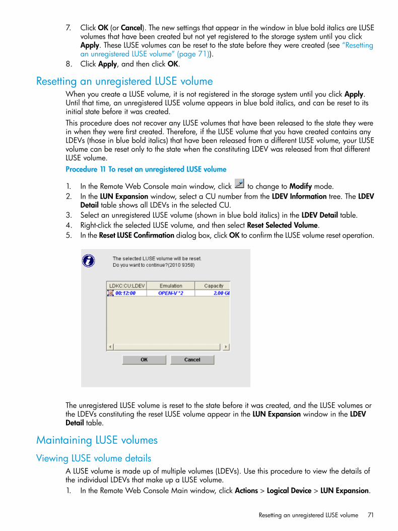
7. Click OK (or Cancel). The new settings that appear in the window in blue bold italics are LUSEvolumes that have been created but not yet registered to the storage system until you clickApply. These LUSE volumes can be reset to the state before they were created (see “Resettingan unregistered LUSE volume” (page 71)).
8. Click Apply, and then click OK.
Resetting an unregistered LUSE volumeWhen you create a LUSE volume, it is not registered in the storage system until you click Apply.Until that time, an unregistered LUSE volume appears in blue bold italics, and can be reset to itsinitial state before it was created.This procedure does not recover any LUSE volumes that have been released to the state they werein when they were first created. Therefore, if the LUSE volume that you have created contains anyLDEVs (those in blue bold italics) that have been released from a different LUSE volume, your LUSEvolume can be reset only to the state when the constituting LDEV was released from that differentLUSE volume.Procedure 11 To reset an unregistered LUSE volume
1. In the Remote Web Console main window, click to change to Modify mode.2. In the LUN Expansion window, select a CU number from the LDEV Information tree. The LDEV
Detail table shows all LDEVs in the selected CU.3. Select an unregistered LUSE volume (shown in blue bold italics) in the LDEV Detail table.4. Right-click the selected LUSE volume, and then select Reset Selected Volume.5. In the Reset LUSE Confirmation dialog box, click OK to confirm the LUSE volume reset operation.
The unregistered LUSE volume is reset to the state before it was created, and the LUSE volumes orthe LDEVs constituting the reset LUSE volume appear in the LUN Expansion window in the LDEVDetail table.
Maintaining LUSE volumes
Viewing LUSE volume detailsA LUSE volume is made up of multiple volumes (LDEVs). Use this procedure to view the details ofthe individual LDEVs that make up a LUSE volume.1. In the Remote Web Console Main window, click Actions > Logical Device > LUN Expansion.
Resetting an unregistered LUSE volume 71

2. Click to change to Modify mode.3. In the LUN Expansion window, select a LUSE volume in the LDEV Detail table.4. Right-click the selected LUSE volume, and then select LUSE Detail.5. In the LUSE Detail dialog box, review the details. After viewing this list, click Close.
Changing capacity on a LUSE volumeYou can change the capacity of a LUSE volume using one of these methods:
• Expand LUSE capacityTo expand the capacity of a LUSE volume, select a LUSE volume that you want to expand,and then add LDEVs or LUSE volumes. Or first select LDEVs or LUSE volumes that you want toadd, and then select a LUSE volume to be expanded.
• Reduce LUSE capacityYou may not reduce the capacity of an existing LUSE volume. If you want to reduce the capacityof a LUSE volume, you must first release the LUSE volume and then redefine the LUSE volume(see “Releasing a LUSE volume” (page 72)). Then select LDEVs of the desired size and createthe LUSE volume again (see “Creating a LUSE volume ” (page 68)).
WARNING! Move or back up your data, or both, before releasing a LUSE volume.
Releasing a LUSE volumeYou must release a LUSE volume before you can reduce capacity in an existing LUSE volume.
WARNING! Move or back up your data, or both, before releasing a LUSE volume. After releasinga LUSE volume, data will be erased.
To release a LUSE volume1. In the Remote Web Console Main window, click Actions > Logical Device >LUN Expansion.
2. Click to change to Modify mode.3. Select a CU number from the LDEV Information tree. The LDEV Detail table lists all LDEVs in
the selected CU.4. In the LUN Expansion window, select a LUSE volume in the LDEV Detail table.5. Right-click the selected LUSE volume, and then select Release LUSE Volume.6. In the Release LUSE Volume Confirmation dialog box, verify that the LUSE volumes listed are
the ones that you want released.
72 Configuring expanded LU provisioning
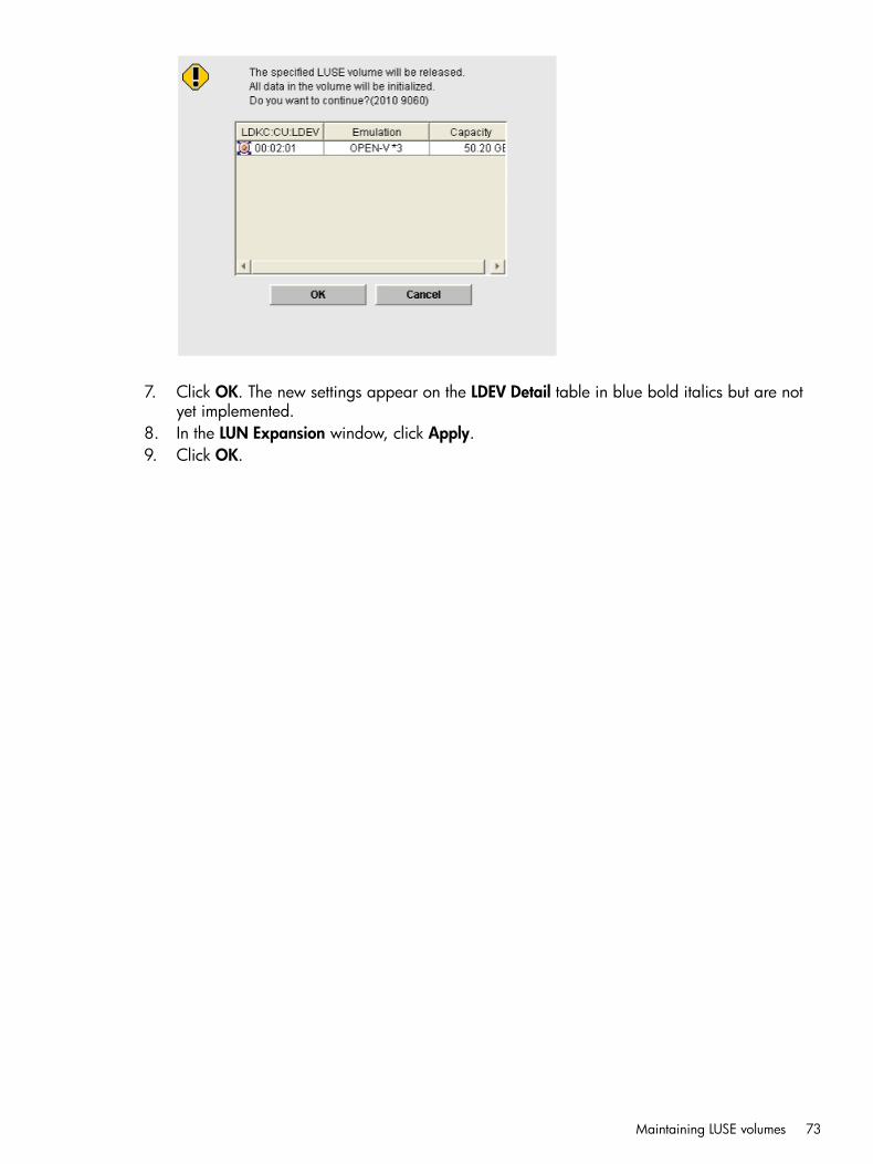
7. Click OK. The new settings appear on the LDEV Detail table in blue bold italics but are notyet implemented.
8. In the LUN Expansion window, click Apply.9. Click OK.
Maintaining LUSE volumes 73
5 Configuring thin provisioningThin provisioning technology allows you to allocate virtual storage capacity based on anticipatedfuture capacity needs, using virtual volumes instead of physical disks.Thin provisioning is an optional provisioning strategy for both open and mainframe systems. Thinprovisioning is implemented with Thin Provisioning by creating one or more Thin Provisioning pools(THP pools) of physical storage space.
Thin Provisioning overviewThin Provisioning is an advanced thin-provisioning software product that allows you to save moneyon storage purchases and reduce storage management expenses.You can operate Thin Provisioning using both Remote Web Console software and the RAIDManager.
Smart Tiers overviewSmart Tiers is a software product that helps you reduce storage costs and increase storageperformance by supporting a volume configured with different storage media of different cost andperformance capabilities. This support allows you to allocate data areas with heavy I/O loads tohigher-speed media and to allocate data areas with low I/O loads to lower-speed media. In thisway, you can make the best use of the capabilities of installed storage media. Up to three storagetiers consisting of different types of data drives are supported in a single pool of storage.
Thin provisioning requirements
License requirementsBefore you operate Thin Provisioning, the Thin Provisioning program product must have beeninstalled on the PC on which Remote Web Console has been installed. For this, you will need topurchase the Thin Provisioning Software license.Before you operate Smart Tiers, the Thin Provisioning and the Smart Tiers program products musthave been installed. For this, you will need to purchase the Smart Tiers license as well as the ThinProvisioning Software license.You will need the Smart Tiers license for the total capacity of the pool for which the tier functionis enabled.If the V-VOL of Thin Provisioning or Smart Tiers are used for the P-VOLs and S-VOLs of BusinessCopy, Continuous Access Synchronous, Continuous Access Journal, or External Storage AccessManager, you will need the Business Copy, Continuous Access Synchronous, Continuous AccessJournal, and External Storage Access Manager license for the total pool capacity in use.If the THP-VOLs of Thin Provisioning or Smart Tiers are used for the P-VOLs and S-VOLs of BusinessCopy, Continuous Access Synchronous, Continuous Access Journal, or External Storage AccessManager, you will need the Business Copy, Continuous Access Synchronous, Continuous AccessJournal, and External Storage Access Manager license for the total pool capacity in use.If you exceed the licensed capacity, you will be able to use the additional unlicensed capacity for30 days. After 30 days, you will not be able to perform Business Copy operations except fordeleting pairs. After 30 days, you will not be able to perform Continuous Access Synchronous,Continuous Access Journal, and External Storage Access Manager operations except for suspendingcopy operations or deleting pairs. For more information about temporary license capacity, see theHP XP P9000 Remote Web Console User Guide.
74 Configuring thin provisioning
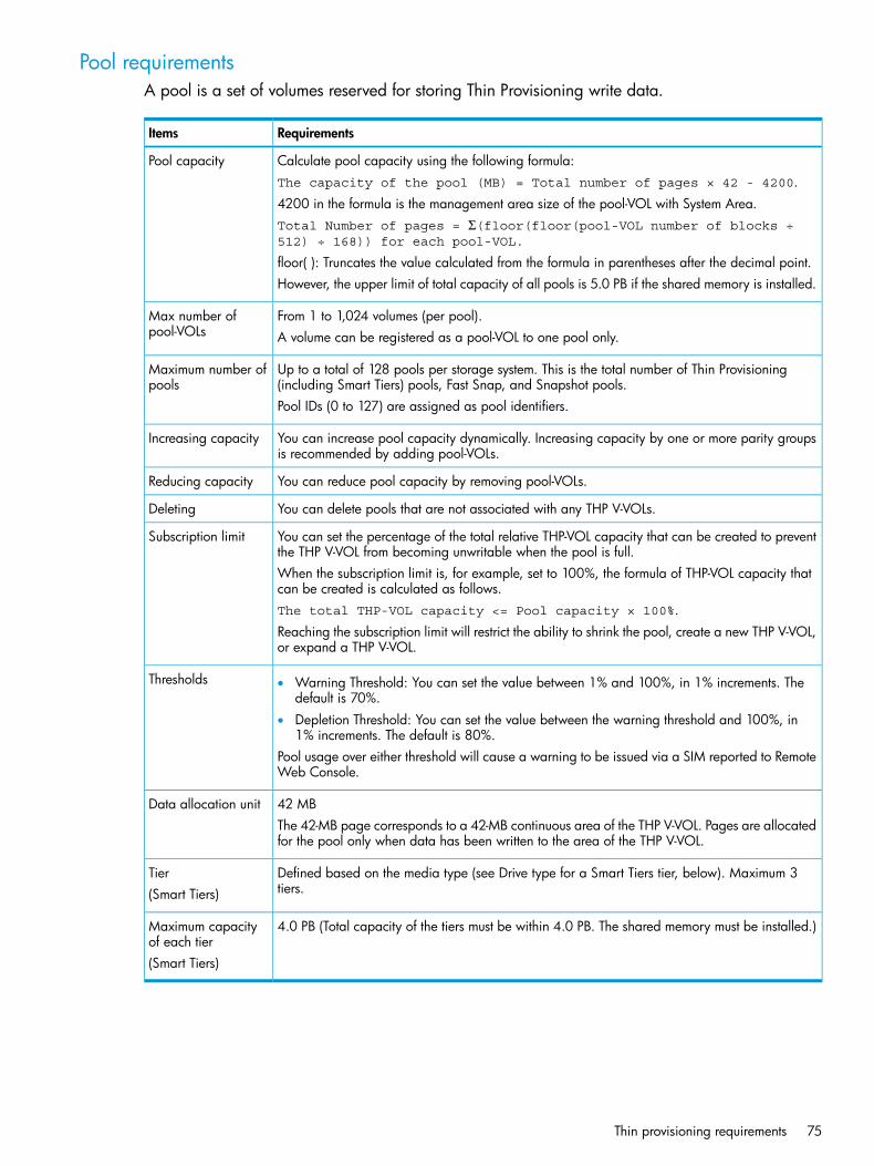
Pool requirementsA pool is a set of volumes reserved for storing Thin Provisioning write data.
RequirementsItems
Calculate pool capacity using the following formula:Pool capacityThe capacity of the pool (MB) = Total number of pages × 42 - 4200.4200 in the formula is the management area size of the pool-VOL with System Area.Total Number of pages = Σ(floor(floor(pool-VOL number of blocks ÷512) ÷ 168)) for each pool-VOL.
floor( ): Truncates the value calculated from the formula in parentheses after the decimal point.However, the upper limit of total capacity of all pools is 5.0 PB if the shared memory is installed.
From 1 to 1,024 volumes (per pool).Max number ofpool-VOLs A volume can be registered as a pool-VOL to one pool only.
Up to a total of 128 pools per storage system. This is the total number of Thin Provisioning(including Smart Tiers) pools, Fast Snap, and Snapshot pools.
Maximum number ofpools
Pool IDs (0 to 127) are assigned as pool identifiers.
You can increase pool capacity dynamically. Increasing capacity by one or more parity groupsis recommended by adding pool-VOLs.
Increasing capacity
You can reduce pool capacity by removing pool-VOLs.Reducing capacity
You can delete pools that are not associated with any THP V-VOLs.Deleting
You can set the percentage of the total relative THP-VOL capacity that can be created to preventthe THP V-VOL from becoming unwritable when the pool is full.
Subscription limit
When the subscription limit is, for example, set to 100%, the formula of THP-VOL capacity thatcan be created is calculated as follows.The total THP-VOL capacity <= Pool capacity × 100%.Reaching the subscription limit will restrict the ability to shrink the pool, create a new THP V-VOL,or expand a THP V-VOL.
Thresholds • Warning Threshold: You can set the value between 1% and 100%, in 1% increments. Thedefault is 70%.
• Depletion Threshold: You can set the value between the warning threshold and 100%, in1% increments. The default is 80%.
Pool usage over either threshold will cause a warning to be issued via a SIM reported to RemoteWeb Console.
42 MBData allocation unitThe 42-MB page corresponds to a 42-MB continuous area of the THP V-VOL. Pages are allocatedfor the pool only when data has been written to the area of the THP V-VOL.
Defined based on the media type (see Drive type for a Smart Tiers tier, below). Maximum 3tiers.
Tier(Smart Tiers)
4.0 PB (Total capacity of the tiers must be within 4.0 PB. The shared memory must be installed.)Maximum capacityof each tier(Smart Tiers)
Thin provisioning requirements 75

Pool-VOL requirementsPool-VOLs make up a THP-pool.
RequirementsItems
Logical volume (LDEV)Volume typeWhile pool-VOLs can coexist with other volumes in the same parity group, for best performance:
• pool-VOLs for a pool should not share a parity group with other volumes.
• pool-VOLs should not be located on concatenated parity groups.
Pool-VOLs cannot be used for any other purpose. For instance, you cannot specify the followingvolumes as Thin Provisioning and Smart Tiers pool-VOLs:
• Volumes used by Business Copy, Auto LUN, Continuous Access Synchronous, External StorageAccess Manager, or Continuous Access Journal
• LUSE volumes
• Volumes defined by Cache Residency
• Volumes already registered in Fast Snap, Snapshot, Thin Provisioning, or Smart Tiers pools
• Volumes used as Fast Snap, Snapshot P-VOLs or S-VOLs
• Data Retention volumes with a Protect, Read Only, or S-VOL Disable attribute
• Volumes whose LDEV status is other than Normal or Normal (Quick Format)You cannot specify volumes in blocked status or volumes in copying process.
• System disks
• Command devices
• Quorum disks
OPEN-VEmulation type
All RAID levels of pool-VOLs can be added. Pool-VOLs of RAID 5, RAID 6, RAID 1, and theexternal volume can coexist in the same pool. For pool-VOLs in the same pool:
RAID level for a ThinProvisioning pool
• RAID 6 is the recommended RAID level for pool-VOLs, especially for a pool where the recoverytime of a pool failure due to a drive failure is not acceptable.
• RAID 1 pool-VOLs with SATA-E drive types cannot be registered in a pool.
• Pool-VOLs of the same drive type with different RAID levels can coexist in the same pool.Note that HP recommends that you use the following configuration:
◦ If there are pool-VOLs of the same hard disk drive type in a pool, unify the RAID levels.
◦ Although you can set four or more of hard disk drive types for pool-VOLs in the samepool, you should use three or fewer types.
• Pool-VOLs on external volumes cannot have a mix of cache modes set to enable and disable.
• For internal and external pool-VOLs to coexist, the cache mode of the external volume mustbe set to enable.
• If Enabled is displayed for Mixable in the Remote Web Console window, the volumes ofRAID 1, RAID 5, RAID 6 and external volumes can coexist in the same pool. If Disabled isdisplayed for Mixable in the Remote Web Console window, the volumes of RAID 1, RAID5, RAID 6 and external volumes cannot coexist in the same pool.
All RAID levels of pool-VOLs can be added. Pool-VOLs of RAID 5, RAID 6, RAID 1, and theexternal volume can coexist in the same pool.
RAID level for aSmart Tiers pool
For pool-VOLs in a pool:
• RAID 6 is the recommended RAID level for pool-VOLs, especially for a pool where the recoverytime of a pool failure due to a drive failure is not acceptable.
• RAID 1 pool-VOLs with SATA-E drive types cannot be registered in a pool.
76 Configuring thin provisioning
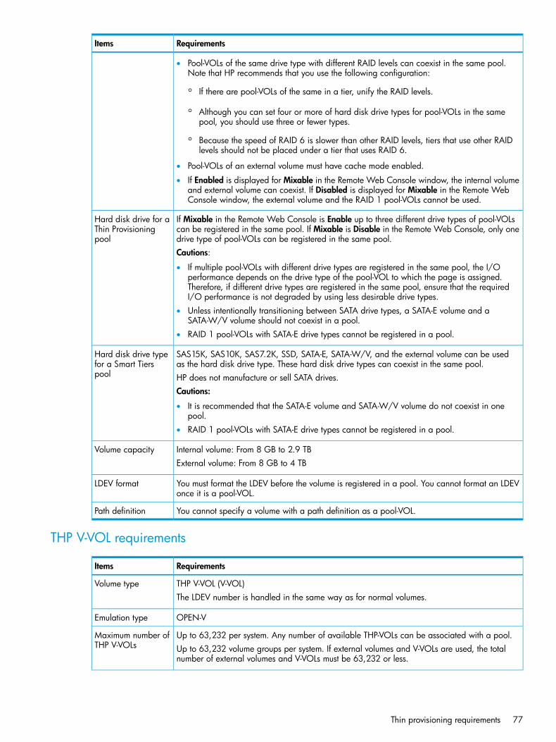
RequirementsItems
• Pool-VOLs of the same drive type with different RAID levels can coexist in the same pool.Note that HP recommends that you use the following configuration:
◦ If there are pool-VOLs of the same in a tier, unify the RAID levels.
◦ Although you can set four or more of hard disk drive types for pool-VOLs in the samepool, you should use three or fewer types.
◦ Because the speed of RAID 6 is slower than other RAID levels, tiers that use other RAIDlevels should not be placed under a tier that uses RAID 6.
• Pool-VOLs of an external volume must have cache mode enabled.
• If Enabled is displayed for Mixable in the Remote Web Console window, the internal volumeand external volume can coexist. If Disabled is displayed for Mixable in the Remote WebConsole window, the external volume and the RAID 1 pool-VOLs cannot be used.
If Mixable in the Remote Web Console is Enable up to three different drive types of pool-VOLscan be registered in the same pool. If Mixable is Disable in the Remote Web Console, only onedrive type of pool-VOLs can be registered in the same pool.
Hard disk drive for aThin Provisioningpool
Cautions:
• If multiple pool-VOLs with different drive types are registered in the same pool, the I/Operformance depends on the drive type of the pool-VOL to which the page is assigned.Therefore, if different drive types are registered in the same pool, ensure that the requiredI/O performance is not degraded by using less desirable drive types.
• Unless intentionally transitioning between SATA drive types, a SATA-E volume and aSATA-W/V volume should not coexist in a pool.
• RAID 1 pool-VOLs with SATA-E drive types cannot be registered in a pool.
SAS15K, SAS10K, SAS7.2K, SSD, SATA-E, SATA-W/V, and the external volume can be usedas the hard disk drive type. These hard disk drive types can coexist in the same pool.
Hard disk drive typefor a Smart Tierspool HP does not manufacture or sell SATA drives.
Cautions:
• It is recommended that the SATA-E volume and SATA-W/V volume do not coexist in onepool.
• RAID 1 pool-VOLs with SATA-E drive types cannot be registered in a pool.
Internal volume: From 8 GB to 2.9 TBVolume capacityExternal volume: From 8 GB to 4 TB
You must format the LDEV before the volume is registered in a pool. You cannot format an LDEVonce it is a pool-VOL.
LDEV format
You cannot specify a volume with a path definition as a pool-VOL.Path definition
THP V-VOL requirements
RequirementsItems
THP V-VOL (V-VOL)Volume typeThe LDEV number is handled in the same way as for normal volumes.
OPEN-VEmulation type
Up to 63,232 per system. Any number of available THP-VOLs can be associated with a pool.Maximum number ofTHP V-VOLs Up to 63,232 volume groups per system. If external volumes and V-VOLs are used, the total
number of external volumes and V-VOLs must be 63,232 or less.
Thin provisioning requirements 77

RequirementsItems
Volume capacity from 46.87 MB to 59.9 TB per volume.Volume capacity• TB: 0.01 to 59.99
• GB: 0.04 to 61,439.99
• MB: 46.87 to 62,914,556.25
• Blocks: 96,000 to 128,849,011,200
However, if you use the volume as a P-VOL or S-VOL of Business Copy, Auto LUN V2, ContinuousAccess Synchronous, Continuous Access Journal, or External Storage Access Manager, thevolume capacity must be 4 TB or less.Total maximum volume capacity of 5.0 PB per storage system.
Available.Path definition
Available (Quick Format is not available.)LDEV formatSystem Option Mode 867 OFFWhen you format an LDEV on the THP V-VOLs, the storage system initializes data only in theconsumed pool pages of the THP V-VOLs. However, after you format an LDEV, the free spacein the pool does not increase because the pages are not released.
NOTE: System Option Mode 867 ON: When you format an LDEV on a THP V-VOL, the capacitymapped to the THP V-VOL is released to the pool as free space.
Requirements for increasing THP V-VOL capacityYou can increase THP V-VOL capacity up to 59.9 TB. To notify the host that the THP V-VOL capacityhas been increased, make sure host mode option 40 is enabled. Processing differs as follows,depending on the value of host mode option 40:
• When host mode option 40 is not enabled, the host will not be notified that the THP V-VOLcapacity has been increased. Therefore, the THP V-VOL data has to be read again by yourstorage system after the capacity is increased.
• When host mode option 40 is enabled, the host is notified that the THP V-VOL capacity hasincreased. If the operating system cannot recognize the value of capacity that was increased,the THP V-VOL data has to be read again by your storage system.
The following requirements are important when increasing the THP V-VOL capacity:
• The THP V-VOL to be increased is not shared with a P9500 product that does not allowincreasing the THP V-VOL (See “Increasing THP V-VOL capacity” (page 158)).
• The THP V-VOL is not undergoing LDEV formatting.
78 Configuring thin provisioning

• The capacity to be added to the THP V-VOL must be specified within the range indicatedbelow LDEV Capacity in the Expand V-VOLs window.
• You cannot add capacity to the THP V-VOL while the pool related to the target THP V-VOL isin any one of the following statuses:
◦ Exceeding the subscription limit threshold
◦ In progress of pool capacity shrinking
CAUTION: When increasing THP V-VOL capacity, do not perform the following operations.When you perform these operations, do not increase THP V-VOL capacity.• Operations using Virtual LUN
• Operations using Cache Residency
• Creating THP V-VOLs
• Restoring pools
• Deleting THP V-VOLs
• Operations to increase the THP V-VOL capacity in another instance of RAID Manager
• Maintenance of your storage system
After increasing THP V-VOL capacity, click Refresh in Remote Web Console, and then confirm thatthe THP V-VOL is increased. If the THP V-VOL capacity is not increased, wait a while, click Refreshagain, and confirm that the THP V-VOL is increased. If you perform a Remote Web Consoleoperation without making sure that the THP V-VOL is increased, operations from Remote WebConsole may fail.If either of the following operations is being performed, the THP V-VOL capacity might not beincreased:
• Auto LUN
• Quick Restore by Business Copy
Operating system and file system capacityOperating systems and file systems when initializing a P-VOL will consume some Thin Provisioningpool space. Some combinations will initially take up little pool space, while other combinationswill take as much pool space as the virtual capacity of the THP V-VOL.The following table shows the effects of some combinations of operating system and file systemcapacity. For more information, contact your HP representative.
Pool Capacity ConsumedMetadata WritingFile SystemOS
Small (one page)Writes metadata to first block.NTFSWindows Server2003 and WindowsServer 2008*
If file update is repeated, allocatedcapacity increases when files areupdated (overwritten). Therefore, theeffectiveness of reducing the poolcapacity consumption decreases.1
Depends upon allocation group size.The amount of pool space consumed
Writes metadata in AllocationGroup Size intervals.
XFSLinux
will be approximately [THP V-VOLSize]*[42 MB/Allocation GroupSize]1
About 33% of the size of the THPV-VOL.
Writes metadata in 128-MBincrements.
Ext2
Thin provisioning requirements 79
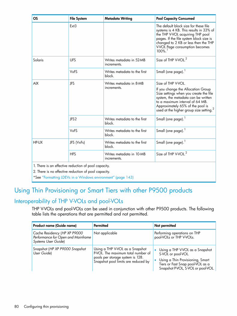
Pool Capacity ConsumedMetadata WritingFile SystemOS
Ext3 The default block size for these filesystems is 4 KB. This results in 33% ofthe THP V-VOL acquiring THP poolpages. If the file system block size ischanged to 2 KB or less then the THPV-VOL Page consumption becomes100%.1
Size of THP V-VOL.2Writes metadata in 52-MBincrements.
UFSSolaris
Small (one page).1Writes metadata to the firstblock.
VxFS
Size of THP V-VOL.Writes metadata in 8-MBincrements.
JFSAIXIf you change the Allocation GroupSize settings when you create the filesystem, the metadata can be writtento a maximum interval of 64 MB.Approximately 65% of the pool isused at the higher group size setting.2
Small (one page).1Writes metadata to the firstblock.
JFS2
Small (one page).1Writes metadata to the firstblock.
VxFS
Small (one page).1Writes metadata to the firstblock.
JFS (VxFs)HP-UX
Size of THP V-VOL.2Writes metadata in 10-MBincrements.
HFS
1. There is an effective reduction of pool capacity.2. There is no effective reduction of pool capacity.*See “Formatting LDEVs in a Windows environment” (page 143)
Using Thin Provisioning or Smart Tiers with other P9500 products
Interoperability of THP V-VOLs and pool-VOLsTHP V-VOLs and pool-VOLs can be used in conjunction with other P9500 products. The followingtable lists the operations that are permitted and not permitted.
Not permittedPermittedProduct name (Guide name)
Performing operations on THPpool-VOLs or THP V-VOLs.
Not applicableCache Residency (HP XP P9000Performance for Open and MainframeSystems User Guide)
Using a THP V-VOL as a SnapshotP-VOL. The maximum total number of
Snapshot (HP XP P9000 SnapshotUser Guide)
• Using a THP V-VOL as a SnapshotS-VOL or pool-VOL.
pools per storage system is 128.• Using a Thin Provisioning, Smart
Tiers or Fast Snap pool-VOL as aSnapshot P-VOL, S-VOL or pool-VOL.
Snapshot pool limits are reduced by
80 Configuring thin provisioning
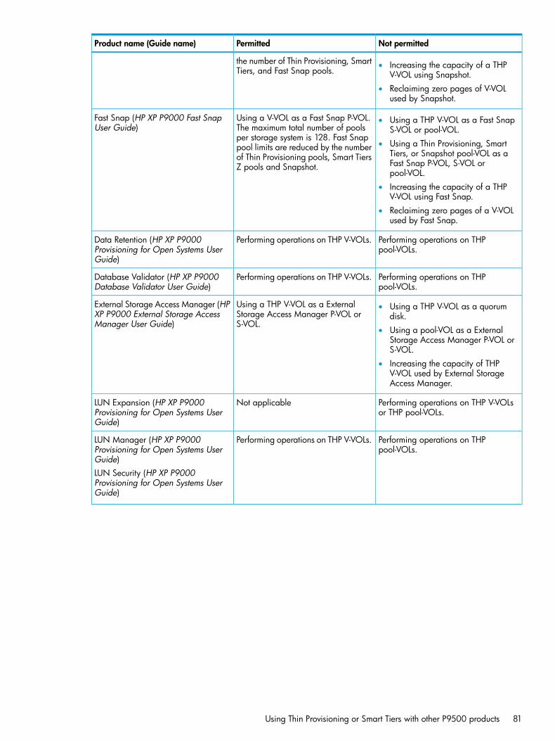
Not permittedPermittedProduct name (Guide name)
the number of Thin Provisioning, SmartTiers, and Fast Snap pools.
• Increasing the capacity of a THPV-VOL using Snapshot.
• Reclaiming zero pages of V-VOLused by Snapshot.
Using a V-VOL as a Fast Snap P-VOL.The maximum total number of pools
Fast Snap (HP XP P9000 Fast SnapUser Guide)
• Using a THP V-VOL as a Fast SnapS-VOL or pool-VOL.
per storage system is 128. Fast Snap• Using a Thin Provisioning, Smart
Tiers, or Snapshot pool-VOL as apool limits are reduced by the numberof Thin Provisioning pools, Smart TiersZ pools and Snapshot. Fast Snap P-VOL, S-VOL or
pool-VOL.• Increasing the capacity of a THP
V-VOL using Fast Snap.• Reclaiming zero pages of a V-VOL
used by Fast Snap.
Performing operations on THPpool-VOLs.
Performing operations on THP V-VOLs.Data Retention (HP XP P9000Provisioning for Open Systems UserGuide)
Performing operations on THPpool-VOLs.
Performing operations on THP V-VOLs.Database Validator (HP XP P9000Database Validator User Guide)
Using a THP V-VOL as a ExternalStorage Access Manager P-VOL orS-VOL.
External Storage Access Manager (HPXP P9000 External Storage AccessManager User Guide)
• Using a THP V-VOL as a quorumdisk.
• Using a pool-VOL as a ExternalStorage Access Manager P-VOL orS-VOL.
• Increasing the capacity of THPV-VOL used by External StorageAccess Manager.
Performing operations on THP V-VOLsor THP pool-VOLs.
Not applicableLUN Expansion (HP XP P9000Provisioning for Open Systems UserGuide)
Performing operations on THPpool-VOLs.
Performing operations on THP V-VOLs.LUN Manager (HP XP P9000Provisioning for Open Systems UserGuide)LUN Security (HP XP P9000Provisioning for Open Systems UserGuide)
Using Thin Provisioning or Smart Tiers with other P9500 products 81

Not permittedPermittedProduct name (Guide name)
Using a THP V-VOL as a BusinessCopy P-VOL or S-VOL.
Business Copy (HP XP P9000 BusinessCopy User Guide)
• Using a pool-VOL as a BusinessCopy P-VOL or S-VOL.
• Increasing the capacity of a THPV-VOL used by Business Copy.
• Reclaiming zero pages of a THPV-VOL is determined by the pairstatus. For more information, see“Business Copy pair status forreclaiming zero pages” (page 83).
Using a THP V-VOL as a ContinuousAccess Synchronous P-VOL or S-VOL.
Continuous Access Synchronous (HPXP P9000 Continuous AccessSynchronous User Guide)
• Using a pool-VOL as a ContinuousAccess Synchronous P-VOL orS-VOL.
• Increasing the capacity of THPV-VOL used by Continuous AccessSynchronous.
Using a THP V-VOL as a ContinuousAccess Journal P-VOL or S-VOL.
Continuous Access Journal (HP XPP9000 Continuous Access JournalUser Guide)
• Using a THP V-VOL as a journalvolume of Continuous AccessJournal.
• Using a THP pool-VOL as aContinuous Access Journal journalvolume, S-VOL, or P-VOL.
• Increasing the capacity of a THPV-VOL used by Continuous AccessJournal.
Increasing the capacity of a volumemapped to the External Storage. If you
Enabling volumes created by ExternalStorage to be used as pool-VOLs.
External Storage (HP XP P9000External Storage for Open andMainframe Systems User Guide) try to increase the capacity of the
external volume, the capacity of thevolume will not change in the ExternalStorage. Volumes used as pool volumeswould need to be deleted (shrunk) fromthe pool before being expanded.
Performing Virtual LUN operations onvolumes that are already registered ina THP pool.
Registering Virtual LUN volumes inThin Provisioning pools.
Virtual LUN (HP XP P9000Provisioning for Open Systems UserGuide)
Not applicablePerforming operations on THP V-VOLsand pool-VOLs.
Cache Partition (HP XP P9000Performance for Open and MainframeSystems User Guide)
Using a THP V-VOL as a migrationsource or a migration target.
Auto LUN (HP XP P9000 Auto LUNUser Guide)
• Using on pool-VOLs.
• Increasing the capacity of THPV-VOL used by Auto LUN.
• Reclaiming zero pages of V-VOLused by Auto LUN.
Use on THP V-VOLs.Volume Shredder (HP XP P9000Volume Shredder for Open andMainframe Systems User Guide)
• Using on pool-VOLs.
• Increasing the capacity of THPV-VOL used by Volume Shredder.
• Reclaiming zero pages of V-VOLused by Volume Shredder.
82 Configuring thin provisioning

Business Copy pair status for reclaiming zero pagesYou can use this table to determine whether reclaiming zero pages is possible for a particular pairstatus
Reclaim zero pages from RAID ManagerReclaim zero pages fromRemote Web Console
Pair status
EnabledEnabledSMPL
DisabledDisabledCOPY(PD)/COPY
DisabledDisabledPAIR
DisabledDisabledCOPY(SP)
DisabledDisabledPSUS(SP)/PSUS
EnabledEnabledPSUS
DisabledDisabledCOPY(RS)/COPY
DisabledDisabledCOPY(RS-R)/RCPY
DisabledDisabledPSUE
Continuous Access SynchronousYou can use Thin Provisioning or Smart Tiers in combination with Continuous Access Synchronousto replicate V-VOLs. The following figure illustrates the interaction when the Continuous AccessSynchronous P-VOL and S-VOL are also V-VOLs.
Figure 1 Thin Provisioning or Smart Tiers and Continuous Access Synchronous
This table shows the supported Continuous Access Synchronous and Thin Provisioning or SmartTiers combinations.
ExplanationContinuous AccessSynchronous S-VOL
Continuous AccessSynchronous P-VOL
Supported.THP V-VOLsTHP V-VOLs
Supported.Normal (ordinary) volumesTHP V-VOLs
Supported.THP V-VOLsNormal (ordinary) volumesNote, however, that this combination consumes the sameamount of pool capacity as the original normal volume(P-VOL).
You cannot specify a Thin Provisioning or Smart Tiers pool-VOL as a Continuous Access SynchronousP-VOL and S-VOL.
Using Thin Provisioning or Smart Tiers with other P9500 products 83
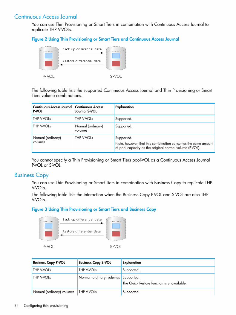
Continuous Access JournalYou can use Thin Provisioning or Smart Tiers in combination with Continuous Access Journal toreplicate THP V-VOLs.
Figure 2 Using Thin Provisioning or Smart Tiers and Continuous Access Journal
The following table lists the supported Continuous Access Journal and Thin Provisioning or SmartTiers volume combinations.
ExplanationContinuous AccessJournal S-VOL
Continuous Access JournalP-VOL
Supported.THP V-VOLsTHP V-VOLs
Supported.Normal (ordinary)volumes
THP V-VOLs
Supported.THP V-VOLsNormal (ordinary)volumes Note, however, that this combination consumes the same amount
of pool capacity as the original normal volume (P-VOL).
You cannot specify a Thin Provisioning or Smart Tiers pool-VOL as a Continuous Access JournalP-VOL or S-VOL.
Business CopyYou can use Thin Provisioning or Smart Tiers in combination with Business Copy to replicate THPV-VOLs.The following table lists the interaction when the Business Copy P-VOL and S-VOL are also THPV-VOLs.
Figure 3 Using Thin Provisioning or Smart Tiers and Business Copy
ExplanationBusiness Copy S-VOLBusiness Copy P-VOL
Supported.THP V-VOLsTHP V-VOLs
Supported.Normal (ordinary) volumesTHP V-VOLsThe Quick Restore function is unavailable.
Supported.THP V-VOLsNormal (ordinary) volumes
84 Configuring thin provisioning
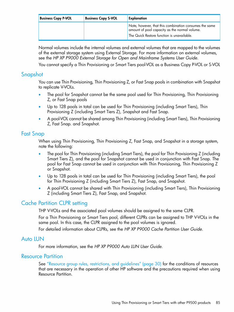
ExplanationBusiness Copy S-VOLBusiness Copy P-VOL
Note, however, that this combination consumes the sameamount of pool capacity as the normal volume.The Quick Restore function is unavailable.
Normal volumes include the internal volumes and external volumes that are mapped to the volumesof the external storage system using External Storage. For more information on external volumes,see the HP XP P9000 External Storage for Open and Mainframe Systems User Guide.You cannot specify a Thin Provisioning or Smart Tiers pool-VOL as a Business Copy P-VOL or S-VOL
SnapshotYou can use Thin Provisioning, Thin Provisioning Z, or Fast Snap pools in combination with Snapshotto replicate V-VOLs.
• The pool for Snapshot cannot be the same pool used for Thin Provisioning, Thin ProvisioningZ, or Fast Snap pools
• Up to 128 pools in total can be used for Thin Provisioning (including Smart Tiers), ThinProvisioning Z (including Smart Tiers Z), Snapshot and Fast Snap.
• A pool-VOL cannot be shared among Thin Provisioning (including Smart Tiers), Thin ProvisioningZ, Fast Snap. and Snapshot.
Fast SnapWhen using Thin Provisioning, Thin Provisioning Z, Fast Snap, and Snapshot in a storage system,note the following:
• The pool for Thin Provisioning (including Smart Tiers), the pool for Thin Provisioning Z (includingSmart Tiers Z), and the pool for Snapshot cannot be used in conjunction with Fast Snap. Thepool for Fast Snap cannot be used in conjunction with Thin Provisioning, Thin Provisioning Zor Snapshot.
• Up to 128 pools in total can be used for Thin Provisioning (including Smart Tiers), the poolfor Thin Provisioning Z (including Smart Tiers Z), Fast Snap, and Snapshot.
• A pool-VOL cannot be shared with Thin Provisioning (including Smart Tiers), Thin ProvisioningZ (including Smart Tiers Z), Fast Snap, and Snapshot.
Cache Partition CLPR settingTHP V-VOLs and the associated pool volumes should be assigned to the same CLPR.For a Thin Provisioning or Smart Tiers pool, different CLPRs can be assigned to THP V-VOLs in thesame pool. In this case, the CLPR assigned to the pool volumes is ignored.For detailed information about CLPRs, see the HP XP P9000 Cache Partition User Guide.
Auto LUNFor more information, see the HP XP P9000 Auto LUN User Guide.
Resource PartitionSee “Resource group rules, restrictions, and guidelines” (page 30) for the conditions of resourcesthat are necessary in the operation of other HP software and the precautions required when usingResource Partition.
Using Thin Provisioning or Smart Tiers with other P9500 products 85
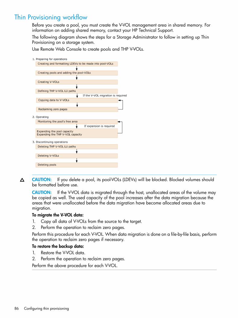
Thin Provisioning workflowBefore you create a pool, you must create the V-VOL management area in shared memory. Forinformation on adding shared memory, contact your HP Technical Support.The following diagram shows the steps for a Storage Administrator to follow in setting up ThinProvisioning on a storage system.Use Remote Web Console to create pools and THP V-VOLs.
CAUTION: If you delete a pool, its pool-VOLs (LDEVs) will be blocked. Blocked volumes shouldbe formatted before use.
CAUTION: If the V-VOL data is migrated through the host, unallocated areas of the volume maybe copied as well. The used capacity of the pool increases after the data migration because theareas that were unallocated before the data migration have become allocated areas due tomigration.To migrate the V-VOL data:1. Copy all data of V-VOLs from the source to the target.2. Perform the operation to reclaim zero pages.Perform this procedure for each V-VOL. When data migration is done on a file-by-file basis, performthe operation to reclaim zero pages if necessary.To restore the backup data:1. Restore the V-VOL data.2. Perform the operation to reclaim zero pages.Perform the above procedure for each V-VOL.
86 Configuring thin provisioning

Smart Tiers
About tiered storageIn a tiered storage environment, storage tiers can be configured to accommodate different categoriesof data. A tier is a group of storage media (pool volumes) in a THP pool. Tiers are determined bya single storage media type. A storage tier can be one type of data drive, including SSD, SAS,SATA, or external volumes. Media of high-speed performance make up the upper tiers. Media oflow-speed response become the lower tiers. Up to a maximum of three tiers can coexist in eachSmart Tiers pool.Categories of data may be based on levels of protection needed, performance requirements,frequency of use, and other considerations. Using different types of storage tiers helps reducestorage costs and improve performance.Because assigning data to particular media may be an ongoing and complex activity, Smart Tierssoftware automatically manages the process based on user-defined policies.As an example of the additional implementation of tiered storage, tier 1 data (such as mission-criticalor recently accessed data) might be stored on expensive and high-quality media such asdouble-parity RAIDs (redundant arrays of independent disks). Tier 2 data (such as financial orseldom-used data) might be stored on less expensive storage media.
Tier monitoring and data relocationSmart Tiers uses tiers to manage data storage. It classifies the specified drives in the pool into tiers(storage hierarchy). Up to three tiers can be defined in a pool depending on the processing capacityof the data drives. Tiering allocates more frequently accessed data to the upper tier and lessfrequently accessed data, stored for a long period of time, to the lower tier.
Smart PoolWith Smart Tiers, you can enable the Smart Pool option for an existing pool. The default is to allowtier relocation for each THP V-VOL. Only the THP V-VOLs for which tier relocation is enabled aresubject to calculation of the tier range value, and tier relocation will be performed on them. If tierrelocation is disabled for all THP V-VOLs in a pool, tier relocation is not performed.
Figure 4 Relationship between Smart Pool and tier relocation
Tier monitoring and relocation cyclesPerformance monitoring and tier relocation can be set to execute in one of two execution modes:Auto and Manual. You can set up execution modes, or switch between modes by using eitherRemote Web Console or RAID Manager.
Smart Tiers 87

In Auto execution mode, monitoring and relocation are continuous and automatically scheduled.In Manual execution mode, the following operations are initiated manually.
• Start monitoring
• Stop monitoring and recalculate tier range values
• Start relocation
• Stop relocation
88 Configuring thin provisioning

In both execution modes, relocation of data is automatically determined based on monitoringresults. The settings for these execution modes can be changed nondisruptively while the pool isin use.
Smart Tiers 89

• Auto execution modeAuto execution mode performs monitoring and tier relocation based on information collectedby monitoring at a specified constant frequency: from 0.5, 1, 2, 4, or 8 hours. All Autoexecution mode cycle frequencies have a starting point at midnight (00:00). For example, ifyou select a 1 hour monitoring period, the starting times would be 00:00, 01:00, 02:00,03:00, and so on.As shown in the following table, the 24-hour monitoring cycle allows you to specify the timesof day to start and stop performance monitoring. The 24-hour monitoring cycle does not haveto start at midnight. Tier relocation begins at the end of each cycle. For more information, see(page 322).
Finish TimesStart TimesMonitoring cycle (hours)
0.5 hours after the start time0.5 hours from 00:00 AM. For example00:00, 00:30, and 01:00
0.5
1 hour after the start time1 hour from 00:00 AM. For example00:00, 01:00, and 02:00
1
2 hours after the start time2 hours from 00:00 AM. For example00:00, 02:00, and 04:00
2
4 hours after the start time4 hours from 00:00 AM. For example00:00, 04:00, and 08:00
4
8 hours after the start time8 hours from 00:00 AM. For example00:00, 08:00, and 16:00
8
Specified timeSpecified time24 (monitoring time periodcan be specified)
If the setting of the monitoring cycle is changed, performance monitoring begins at the newstart time. The collection of monitoring information and tier relocation operations already inprogress are not interrupted when the setting is changed. The next operations are initiated atthe new start time.For example. if the monitoring cycle is changed from 1 hour to 4 hours at 01:30 AM, thecollection of monitoring information and tier relocation in progress at 01:30 AM continues.At 02:00 AM and 03:00 AM, however, monitoring information is not collected and tierrelocation is not performed. In this example, operations could begin again at 04:00 AM, thestart time of the next monitoring cycle.
Figure 5 Collection of monitoring data to tier relocation workflow in auto execution mode
90 Configuring thin provisioning

In auto execution mode, the collection of monitoring data and tier relocation operations areperformed in parallel in the next cycle. Data from these parallel processes are stored in two separatefields.
• Data while monitoring is in progress in the next cycle.
• Fixed monitoring information used in tier reliocation.
Smart Tiers 91

• Manual execution modeYou can start and stop performance monitoring and tier relocation at any time. You shouldkeep the duration of performance monitoring to less than 7 days (168 hours). If performancemonitoring exceeds 7 days, then monitoring stops automatically.Manual execution mode starts and ends monitoring and relocation at the time the commandis issued from Remote Web Console or RAID Manager. You can use scripts, which provideflexibility to control monitoring and relocation tasks based on a schedule for each day of theweek.In manual execution mode, the next monitoring cycle can be started with the collection ofmonitoring data and tier relocation operations performed in parallel. Data from these parallelprocesses are stored in two separate fields.
◦ Data while monitoring is in progress in the next cycle.
◦ Fixed monitoring information used in tier reliocation.
Figure 6 Collection of monitoring data to tier relocation workflow in manual execution mode
Case 1: If the second collection of the monitoring information is finished during the first tierrelocation, the latest monitoring information is the second collection. In that case, the firstcollection of monitoring information is referenced only after the first tier relocation hascompleted.
Figure 7 Second collection of monitoring information finishes before the first tier relocation iscomplete
92 Configuring thin provisioning
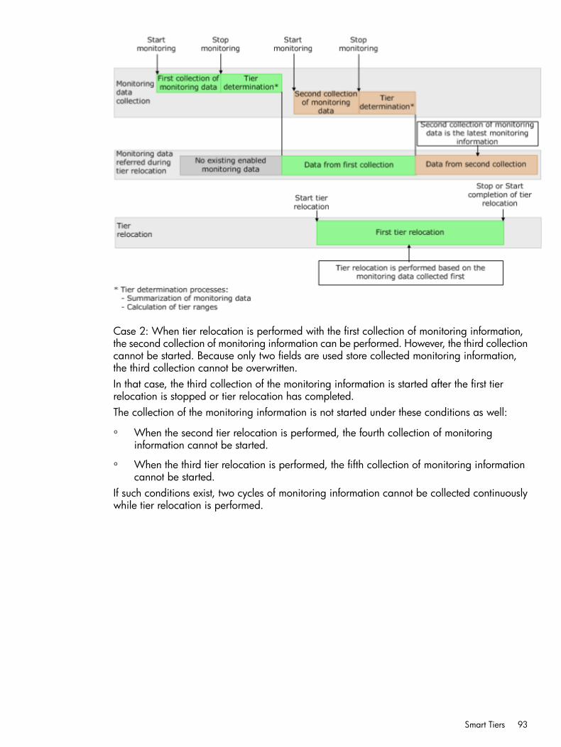
Case 2: When tier relocation is performed with the first collection of monitoring information,the second collection of monitoring information can be performed. However, the third collectioncannot be started. Because only two fields are used store collected monitoring information,the third collection cannot be overwritten.In that case, the third collection of the monitoring information is started after the first tierrelocation is stopped or tier relocation has completed.The collection of the monitoring information is not started under these conditions as well:
◦ When the second tier relocation is performed, the fourth collection of monitoringinformation cannot be started.
◦ When the third tier relocation is performed, the fifth collection of monitoring informationcannot be started.
If such conditions exist, two cycles of monitoring information cannot be collected continuouslywhile tier relocation is performed.
Smart Tiers 93

Figure 8 Third collection of monitoring information while tier relocation is performed
When Smart Tiers is configured for automatic operations, the monitoring feature will be enabledand the time period for monitoring is set for all or part of a 24-hour period. At the end of eachmonitoring period, the relocation task is performed automatically.
Tier relocation flowThe following shows the flow of allocating new pages and migrating them to the appropriate tier.The combination of determining the appropriate storage tier and migrating the pages to theappropriate tier is referred to as tier relocation.
Explanation of the relocation flow:
94 Configuring thin provisioning

1. Allocate pages and map them to THP V-VOLsPages are allocated and mapped to THP V-VOLs on an on-demand basis. Page allocationoccurs when a write is performed to an area of any THP V-VOL that does not already have apage mapped to that location. Normally, a free page is selected for allocation from an uppertier with a free page. If the capacity of the upper tier is insufficient for the allocation, the pagesare allocated to the nearest lower tier. A THP V-VOL set to a tier policy is assigned a newpage that is based on the tier policy setting. The relative tier for new page allocations can bespecified during operations to create and edit LDEVs. If the capacity of all the tiers is insufficient,an error message is sent to the host.
2. Gather I/O load information of each pagePerformance monitoring gathers monitoring information of each page in a pool to determinethe physical I/O load per page in a pool. I/Os associated with page relocation, however,are not counted.
3. Create frequency distribution graphThe frequency distribution graph, which shows the relationship between I/O counts (I/O load)and capacity (total number of pages), is created. You can use the View Tier Properties windowin Remote Web Console to view this graph. The vertical scale of the graph indicates rangesof I/Os per hour and the horizontal scale indicates a capacity that received the I/O level.Note that the horizontal scale is accumulative.
CAUTION: When the number of I/Os is counted, the number of I/Os satisfied by cache hitsare not counted. Therefore, the number of I/Os counted by Performance Monitoring is differentfrom the number of I/Os from the host. The number of I/Os per hour is shown in the graph.If the monitoring time is less than an hour, the number of I/Os shown in the graph might behigher than the actual number of I/Os.
The following is an example of a frequency distribution graph.Monitoring mode settings (see “Monitoring modes” (page 105)) of Period or Continuousinfluences the values shown on the performance graph. Period mode will report the most recentcompleted monitor cycle I/O data on the performance graph. Continuous mode will report aweighted average of I/O data that uses recent monitor cycle data, along with historical dataon the performance graph.
4. Determine the tier range valuesThe page is allocated to the appropriate tier according to performance monitoring information.The tier is determined as follows.1. Determine the tier boundary
The tier range value of a tier is calculated using the frequency distribution graph. Thisacts as a boundary value that separates tiersThe pages of higher I/O load are allocated to the upper tier in sequence. Tier range isdefined as the lowest I/Os per hour (IOPH) value at which the total number of storedpages matches the capacity of the target tier (less some buffer percentage) or the IOPHvalue that will reach the maximum I/O load that the tier should process. The maximumI/O load that should be targeted to a tier is the limit performance value, and the rate ofI/O to the limit performance value of a tier is called the performance utilization percent.
Smart Tiers 95
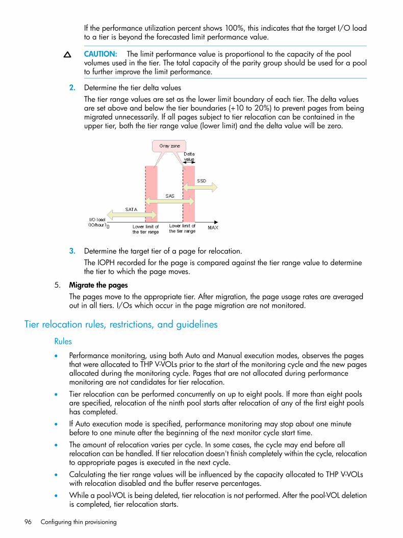
If the performance utilization percent shows 100%, this indicates that the target I/O loadto a tier is beyond the forecasted limit performance value.
CAUTION: The limit performance value is proportional to the capacity of the poolvolumes used in the tier. The total capacity of the parity group should be used for a poolto further improve the limit performance.
2. Determine the tier delta valuesThe tier range values are set as the lower limit boundary of each tier. The delta valuesare set above and below the tier boundaries (+10 to 20%) to prevent pages from beingmigrated unnecessarily. If all pages subject to tier relocation can be contained in theupper tier, both the tier range value (lower limit) and the delta value will be zero.
3. Determine the target tier of a page for relocation.The IOPH recorded for the page is compared against the tier range value to determinethe tier to which the page moves.
5. Migrate the pagesThe pages move to the appropriate tier. After migration, the page usage rates are averagedout in all tiers. I/Os which occur in the page migration are not monitored.
Tier relocation rules, restrictions, and guidelines
Rules
• Performance monitoring, using both Auto and Manual execution modes, observes the pagesthat were allocated to THP V-VOLs prior to the start of the monitoring cycle and the new pagesallocated during the monitoring cycle. Pages that are not allocated during performancemonitoring are not candidates for tier relocation.
• Tier relocation can be performed concurrently on up to eight pools. If more than eight poolsare specified, relocation of the ninth pool starts after relocation of any of the first eight poolshas completed.
• If Auto execution mode is specified, performance monitoring may stop about one minutebefore to one minute after the beginning of the next monitor cycle start time.
• The amount of relocation varies per cycle. In some cases, the cycle may end before allrelocation can be handled. If tier relocation doesn't finish completely within the cycle, relocationto appropriate pages is executed in the next cycle.
• Calculating the tier range values will be influenced by the capacity allocated to THP V-VOLswith relocation disabled and the buffer reserve percentages.
• While a pool-VOL is being deleted, tier relocation is not performed. After the pool-VOL deletionis completed, tier relocation starts.
96 Configuring thin provisioning

• Frequency distribution is unavailable when there is no data provided by performancemonitoring.
• While the frequency distribution graph is being created or the tier range values are beingcalculated, the frequency distribution graph is not available. The time required for determiningthe tier range values varies depending on the number of THP V-VOLs and total capacity. Themaximum time is about 20 minutes.
• To balance the usage levels of all pool-VOLs, rebalancing may be performed after several tierrelocation operations. If rebalancing is in progress, the next cycle of tier relocation might bedelayed.For details on rebalancing, see (page 118).The status of data collection, fixed monitoring, and tier relocation operations are describedin the following table. The latest fixed monitoring information is referenced when tiers arerelocated.
SolutionsTier relocationoperations
Status of fixedmonitoringinformation used intier relocation
Status of datacollection inprogress
Monitoringinformation orexecution conditions
Unnecessary. After thepages are allocated,
Tiers of the pagesare not relocated.
No monitoringinformation on pages.
Pages are notmonitored.
Unallocated pages.
monitoring andrelocation areperformedautomatically.
Unnecessary. After thepages are allocated,
Tiers of the pagesare not relocated.
Only monitoringinformation on pagesis invalid.
Monitoring onpages is reset.
Zero data isdiscarded duringdata monitoring. monitoring and
relocation areperformedautomatically.
N/ATiers of the pagesare not relocated.
Monitoringinformation on thevolume is valid.
Volume ismonitored.
V-VOL settings do notallow tier relocation.
N/ATier relocation ofthe volume issuspended.
Only monitoringinformation on thevolume is invalid.
Volume is notmonitored.
When V-VOLs aredeleted
Collect the monitoringinformation again ifnecessary.2
Suspended.1Monitoringinformation collectedbefore suspension isvalid.
Suspended.When executionmode is changed toManual from Auto orvice versa.
Collect the monitoringinformation again ifnecessary.2
Tier relocation issuspended bypowering OFF andis resumed afterpowering ON.
Monitoringinformation collectedduring the previouscycle is continuouslyvalid.
Monitoring issuspended bypowering OFF andis not resumed evenafter poweringON.2
When the powerswitch is power ONor OFF.
Collect the monitoringinformation again ifnecessary.2
Tiers of the pagesare not relocated.
Monitoringinformation is invalidand the volumes needto be monitored.
The volume is notmonitored.3◦ When Auto LUN
V2 is performed.
◦ When QuickRestore ofBusiness Copy isperformed.
Smart Tiers 97

SolutionsTier relocationoperations
Status of fixedmonitoringinformation used intier relocation
Status of datacollection inprogress
Monitoringinformation orexecution conditions
Collect the monitoringinformation again ifnecessary.2
Continued.No effect on the fixedmonitoringinformation. Themonitoring information
Monitoringinformation iscontinuouslycollected
S-VOLs used wheninitial copies ofContinuous AccessSynchronous or
collected during thecontinuously, but theContinuous Accessprevious cyclecontinues to be valid.
monitoring of thevolumes is reset.4
Journal areperformed.
Relocate tiers again.2Suspended.Fixed monitoringinformation is invalidand is discarded.6
Continued.◦ When the numberof tiers increasesby addingpool-VOLs.4
◦ When thepool-VOLs of thetiers are switchedby addingpool-VOLs.5
◦ When pool-VOLsare deleted.
◦ When tier rank ofthe external LDEVis changed.
After recovering thefaulty area, relocatetiers again.2
Suspended.No effect on the fixedmonitoringinformation. Themonitoring information
Continued.When a cache isblocked.
collected during theprevious cyclecontinues to be valid.
After recovering thefaulty area, relocatetiers again.2
Suspended.No effect on the fixedmonitoringinformation. Themonitoring information
Continued.When an LDEV isblocked. (Pool-VOLor V-VOL)
collected during theprevious cyclecontinues to be valid.
Add pool-VOLs, thencollect monitoring
Suspended.No effect on the fixedmonitoring
Continued.When the depletionthreshold of the pool
information andrelocate tiers again.2
information. Themonitoring informationcollected during the
is nearly exceededduring relocation.
previous cyclecontinues to be valid.
Unnecessary. Therelocation is performed
Suspended.The monitoringinformation collected
At the end time ofexecution cycle,
When executionmode is Auto and the
automatically in thenext cycle.
before monitoringperformance stops isvalid.
data monitoringstops.
execution cycle endsduring tier relocation.
Collect the monitoringinformation again ifnecessary.2
Continued.The monitoringinformation collectedbefore suspension isvalid.
Suspended.When executionmode is Manual andand 7 days elapseafter monitoringstarts.
Notes:
98 Configuring thin provisioning

SolutionsTier relocationoperations
Status of fixedmonitoringinformation used intier relocation
Status of datacollection inprogress
Monitoringinformation orexecution conditions
1. If the version of the DKCMAIN program is earlier than 70-06-0X-XX/XX, tier relocation continues.2. The execution mode is Auto or the script is written in manual execution mode, information is monitored again
and tiers are relocated automatically.3. The volume is monitored at the time of the next execution cycle.4. All pages of the S-VOLs are not allocated, and the monitoring information of the volume is reset. After the
page is allocated to the new page, the monitoring information is collected.5. Example: Pool-VOLs of SAS15K are added to the following configuration 1
◦ Configuration 1 (before change): Tier 1 is SSD, Tier 2 is SAS10K, and Tier 3 is SATA.
◦ Configuration 2 (after change): Tier 1 is SSD, Tier 2 is SAS15K, and Tier 3 is SAS10K and SATA.
6. The monitor information statuses are valid (VAL), invalid (INV), and calculating (PND). See (page 104). In thiscase, the monitor information is invalid (INV). If monitoring is in continue mode, the information of the modeis discarded.
Buffer area of a tierSmart Tiers uses buffer percentages to reserve pages for new page assignments and allow the tierrelocation process. Areas necessary for processing these operations are distributed correspondingto settings used by Smart Tiers. The following describes how processing takes place to handle thebuffer percentages.Buffer space: The following table shows the default rates (rate to capacity of a tier) of buffer spaceused for tier relocation and new page assignments, listed by drive type. The default values can bechanged, if needed, using Remote Web Console or RAID Manager.
Totalbuffer area for new pageassignment
buffer area for tier relocationDrive type
2%0%2%SSD
10%8%2%Non-SSD
Setting external volumes for each tierIf you use external volumes as pool-VOLs, you can put the external volumes in tiers by setting theExternal LDEV Tier Rank for the external volumes. The External LDEV Tier Rank consists of thefollowing three types: High, Middle, and Low. The following examples describe how tiers may beconfigured:
Example 1: When configuring tiers by using external volumes onlyTier 1: External volumes (High)Tier 2: External volumes (Middle)Tier 3: External volumes (Low)
Example 2: When configuring tiers by combining internal volumes and external volumesTier 1: Internal volumes (SSD)Tier 2: External volumes (High)Tier 3: External volumes (Low)
Smart Tiers 99

You can set the External LDEV Tier Rank when creating the pool, changing the pool capacity, orsetting the Edit External LDEV Tier Rank window. The following table explains the performancepriority (from the top) of hard disk drives.
Hard disk drive typePriority
SSD1
SAS 15K rpm2
SAS 10K rpm3
SAS 7.2K rpm4
SATA5
External volume* (High)6
External volume* (Middle)7
External volume* (Low)8
*Displays as External Storage in the Drive Type/RPM.
Reserved pages for relocation operation: A small percentage of pages, normally 2, are reservedper tier to allow relocation to operate. These are the buffer spaces for tier relocation.New page assignment: New pages are assigned based on a number of optional settings. Pagesare then assigned to the next lower tier, leaving a buffer area (2% per tier by default) for tierrelocation. Once 98% of capacity of all tiers is assigned, the remaining 2% of the buffer space isassigned from the upper tier. The buffer space for tier relocation is 2% in all tiers. The followingillustrates the workflow of new page assignment.
Figure 9 Workflow of a new page assignment
Tier relocation workflow: Tier relocation is performed taking advantage of the buffer space allocatedfor tier relocation, as mentioned above. Tier relocation is also performed to secure the spacereserved in each tier for new page assignment. The area is called the buffer space for new pageassignments. When tier relocation is performed, Smart Tiers reserves buffer spaces for relocationand new page assignment.During relocation, a tier may temporarily be assigned over 98% of capacity as well, or well underthe allowance for the buffer areas.Further influence on tier relocation and tier occupancy: The buffer area for tier relocation and newpage assignment will influence the amount that a tier’s capacity is used.
100 Configuring thin provisioning

If the relocation cycle’s duration is not long enough for the allocation moves to all complete, thenthe amount of tier capacity used may not fully represent the desired target levels. Subsequentrelocations should eventually reach the target levels.
Smart Tiers cache specifications and requirementsThe following cache capacity is required when the total capacity is 128 TB:
• Recommended capacity of cache memory for data: 28 GB
• Required capacity of cache memory for control information for using Thin Provisioning: 8 GB
• Required capacity of cache memory for Smart Tiers: 4 GB
• Therefore, in this example 40 GB of capacity of cache memory is required.Note that cache memory is installed in pairs. Therefore, actual capacity is twice the cache memorycapacity. For example, if required controlling information is 8 GB, then actual installed capacityis 16 GB.To decrease the capacity of the cache memory for Smart Tiers, you have to remove Smart Tiers.
Execution modes for tier relocation
Execution modes when using Remote Web ConsoleSmart Tiers performs tier relocations using one of two execution modes: Auto and Manual. Youcan switch between modes by using Remote Web Console.
Auto execution modeIn Auto execution mode, the system automatically and periodically collects monitoring data andperforms tier relocation. You can select an Auto execution cycle of 0.5, 1, 2, 4, or 8 hours, or aspecified time. You can specify the settings for the auto execution mode with Remote Web Console.The following illustrates tier relocation processing in a 2-hour Auto execution mode:
Manual execution modeIn Manual execution mode, you can manually collect monitoring data and relocate a tier. You canissue commands to manually:1. Start monitoring.2. Stop monitoring.3. Perform tier relocation.The following illustrates tier relocation processing in Manual execution mode:
Smart Tiers 101
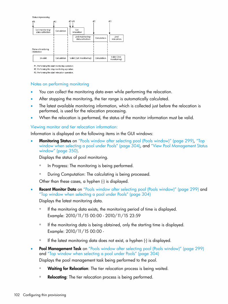
Notes on performing monitoring
• You can collect the monitoring data even while performing the relocation.
• After stopping the monitoring, the tier range is automatically calculated.
• The latest available monitoring information, which is collected just before the relocation isperformed, is used for the relocation processing.
• When the relocation is performed, the status of the monitor information must be valid.
Viewing monitor and tier relocation information:Information is displayed on the following items in the GUI windows:
• Monitoring Status on “Pools window after selecting pool (Pools window)” (page 299), “Topwindow when selecting a pool under Pools” (page 304), and “View Pool Management Statuswindow” (page 350).Displays the status of pool monitoring.
◦ In Progress: The monitoring is being performed.
◦ During Computation: The calculating is being processed.
Other than these cases, a hyphen (-) is displayed.
• Recent Monitor Data on “Pools window after selecting pool (Pools window)” (page 299) and“Top window when selecting a pool under Pools” (page 304)Displays the latest monitoring data.
◦ If the monitoring data exists, the monitoring period of time is displayed.Example: 2010/11/15 00:00 - 2010/11/15 23:59
◦ If the monitoring data is being obtained, only the starting time is displayed.Example: 2010/11/15 00:00 -
◦ If the latest monitoring data does not exist, a hyphen (-) is displayed.
• Pool Management Task on “Pools window after selecting pool (Pools window)” (page 299)and “Top window when selecting a pool under Pools” (page 304)Displays the pool management task being performed to the pool.
◦ Waiting for Relocation: The tier relocation process is being waited.
◦ Relocating: The tier relocation process is being performed.
102 Configuring thin provisioning

For details about the relocation progress rate, check the tier relocation log. For more informationabout the table item for the tier relocation log file, see “Tier relocation log file contents”(page 107).
• Pool Management Task (Status/Progress) on “View Pool Management Status window”(page 350).Displays the status of the pool management task being performed, each V-VOL progress ratioin the pool and its average.
◦ Waiting for Relocation: The tier relocation process is being waited.
◦ Relocating: The tier relocation process is being performed.
For details about the relocation progress rate, check the tier relocation log. For more informationabout the table item for the tier relocation log file, see “Tier relocation log file contents”(page 107).
• Relocation Result on “Pools window after selecting pool (Pools window)” (page 299), “Topwindow when selecting a pool under Pools” (page 304), and “View Pool Management Statuswindow” (page 350).Displays the status of the tier relocation processing.
◦ In Progress: The status of Pool Management Task is Waiting for Relocation or Relocating.
◦ Completed: The tier relocation operation is not in progress, or the tier relocation iscomplete.
◦ Uncompleted (n% relocated): The tier relocation is suspended at the indicated percentageprogression.
◦ -: The pool is not a Smart Tiers or Smart Tiers Z pool.
• Relocation Priority on “Top window when selecting a pool under Pools” (page 304) and “ViewPool Management Status window” (page 350).Displays the relocation priority.
◦ Prioritized: The priority is set to V-VOL.
◦ Blank: The priority is not set to V-VOL.
◦ -: V-VOL is not the Smart Tiers V-VOL or the tier relocation function is disabled.
• Performance Graph on “View Tier Properties window” (page 341).The performance graph for the available monitor information is displayed in the View TierProperties window.
Execution modes when using RAID Manager
Manual execution modeIn Manual execution mode, you can manually collect monitoring data and relocate a tier. You canexecute commands to do the following:1. Start monitoring.2. Stop monitoring.3. Perform tier relocation.The following illustrates tier relocation processing when in Manual execution mode:
Smart Tiers 103
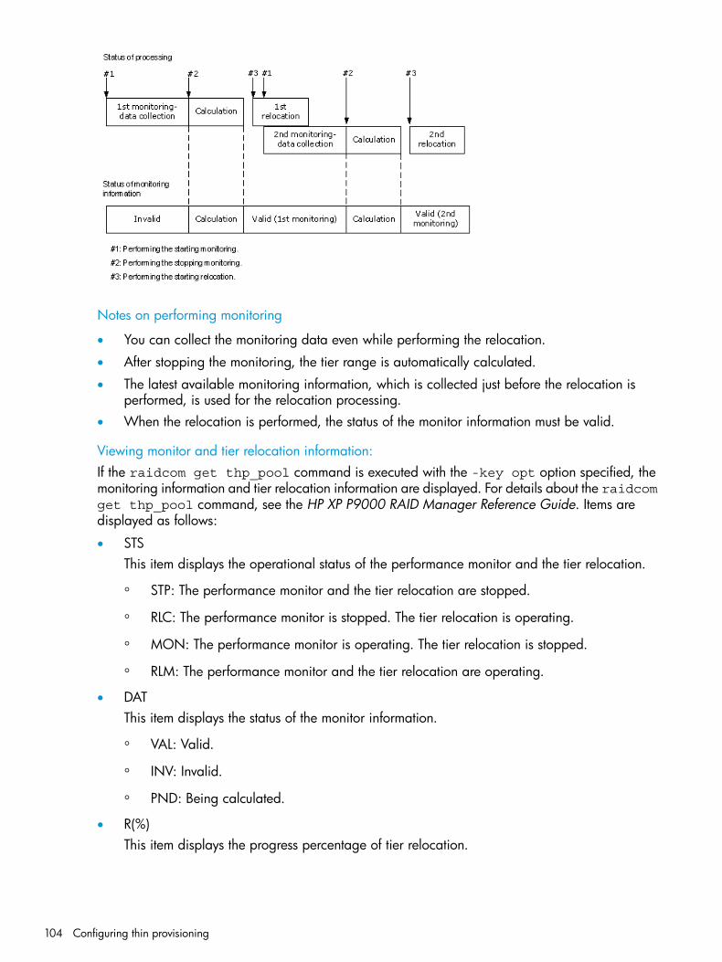
Notes on performing monitoring
• You can collect the monitoring data even while performing the relocation.
• After stopping the monitoring, the tier range is automatically calculated.
• The latest available monitoring information, which is collected just before the relocation isperformed, is used for the relocation processing.
• When the relocation is performed, the status of the monitor information must be valid.
Viewing monitor and tier relocation information:If the raidcom get thp_pool command is executed with the -key opt option specified, themonitoring information and tier relocation information are displayed. For details about the raidcomget thp_pool command, see the HP XP P9000 RAID Manager Reference Guide. Items aredisplayed as follows:
• STSThis item displays the operational status of the performance monitor and the tier relocation.
◦ STP: The performance monitor and the tier relocation are stopped.
◦ RLC: The performance monitor is stopped. The tier relocation is operating.
◦ MON: The performance monitor is operating. The tier relocation is stopped.
◦ RLM: The performance monitor and the tier relocation are operating.
• DATThis item displays the status of the monitor information.
◦ VAL: Valid.
◦ INV: Invalid.
◦ PND: Being calculated.
• R(%)This item displays the progress percentage of tier relocation.
104 Configuring thin provisioning

0 to 99: Shows one of the following statuses.
◦ When the value of STS is RLC or RLM: Relocation is in progress.
◦ When the value of STS is STP or MON: Relocation is suspended at the indicatedpercentage progression.
100: Shows if the relocation operation is not in progress, or the relocation is complete.
Monitoring modesWhen you create or edit a pool, specify the Smart Tiers monitoring mode. The monitoring modeis either the period mode or the continuous mode. If you change the mode from the one to theother while performing the monitoring, the changed setting becomes effective when the nextmonitoring will starts.
Period modePeriod mode is the default setting. If Period mode is enabled, tier range values and page relocationsare determined based solely on the monitoring data from the last complete cycle. Relocation isperformed according to any changes in I/O loads. However, if the I/O loads vary greatly,relocation may not finish in one cycle.
Continuous modeIf Continuous Mode is enabled, by weighting the latest monitoring information and the collectedmonitoring information in the past cycles, the weighted average efficiency is calculated. Byperforming the tier relocation based on the weighted average efficiency, even if a temporarydecrease or an increase of the I/O load occurs, unnecessary relocation can be avoided.
Smart Tiers 105
Cautions when using monitoring modes
• If Continuous mode is used, best practice is to collect monitoring information using the followingexecution modes:
◦ Auto execution mode
◦ Manual execution mode with collecting the periodic monitoring information by defininga script using RAID Manager
If the Manual execution mode is used without scripts, the Continuous monitoring mode canbe set. However, in this case, unexpected results may be calculated because the weightedaverage efficiency is calculated based on very different duration (short and long) periodsinformation obtained in the past cycles.
• When the monitoring mode is set to Continuous, the Remote Web Console window and inRAID Manager display the frequency distributions of each pool and V-VOL calculated by usingthe monitor value on which the weighted calculation is done.These calculated values are the predictive values for the next cycle after successfully relocatingall pages. Therefore, these values may differ from an actual monitoring result when theyappear.In Performance Utilization of each tier, regardless of the type of the monitoring mode setting,the Remote Web Console window and RAID Manager display the monitor values which werealready collected in the current cycle.If you switch the monitoring mode from Period to Continuous or from Continuous to Period,the current cycle’s monitoring data that is being collected is not discarded. However, the datacalculated by using past monitor cycle information on which the weighted calculation is donewill be reset.
Notes on performing monitoring• You can collect a new cycle of monitoring data while performing relocation.
• After monitoring stops, the tier range is automatically calculated.
• The latest available monitoring information, collected just before the relocation is performed,is used for relocation processing.
• When relocation is performed, the status of the monitor information must be valid (VAL).
Downloading the tier relocation log fileYou can download the log file that contains the results of past tier relocations. See “Tier relocationlog file contents” (page 107) for information about the contents of the log.1. Using Remote Web Console, in the Storage Systems tree select Pool.2. In the Pool window, click More Actions > Tier Relocation Log.3. In the progress dialog box, click OK.4. A dialog box opens allowing you to select where to download the file. Specify the folder in
which to download the file, and then click Save.If you change the file name from the default, make sure the file name contains the .tsv extensionbefore saving a renamed file.
106 Configuring thin provisioning

Tier relocation log file contentsThe tier relocation log file is a tab-delimited file and contains the following information:
DescriptionItem
Displays the pool ID.Pool ID
Displays the time and date when the performing the relocation function starts.Start Relocation Time
Displays the time and date when the performing the relocation function ends.End Relocation Time
Displays the section where the relocation result is shown.Result
Displays the execution results that are Normal or Cancel.Status
Displays the following causes of cancellation. A hyphen (-) is displayed when theexecution status is Normal.
Detail
• It was interrupted by annulling the monitor data. Monitoring information with astatus of valid or calculating is discarded under certain conditions.
• It was interrupted by not completing within the cycle of relocation.
• The tier relocation was interrupted because the threshold reached the vicinity ofthe upper limit. The information appears when the pool usage level reaches thedepletion threshold of the pool.
• It was interrupted by a user instruction.
Displays the number of pages that are moved between tiers.Move Page Num
Displays the number of pages that are moved from tier1 to tier2.Tier1->Tier2
Displays the number of pages that are moved from tier1 to tier3.Tier1->Tier3
Displays the number of pages that are moved from tier2 to tier1.Tier2->Tier1
Displays the number of pages that are moved from tier2 to tier3.Tier2->Tier3
Displays the number of pages that are moved from tier3 to tier1.Tier3->Tier1
Displays the number of pages that are moved from tier3 to tier2.Tier3->Tier2
Tiering policyThe tiering policy function is used to assign a specific storage tier to a specific THP V-VOL. A tieringpolicy specifies subset of tiers that is available to a given set of THP V-VOLs.Tier relocation changes the location of previously stored data. It is performed in conformance tothe tiering policy. If a THP V-VOL is initially allocated to a low-speed tier and the tiering policy ischanged to a high-speed tier, relocation is performed in the next cycle.For example, if you set the tiering policy level on a V-VOL(THP V-VOL) to a tier with a high I/Ospeed, the data is always stored on the high-speed tier when relocating tiers. When you use thatV-VOL(THP V-VOL), regardless of the actual size of the I/O load, you can always get high-speedresponses. See “Tiering policy expansion” (page 108).When you create the THP V-VOL, you can designate one of six existing tiering policies and defineup to 26 new tiering policies. See “Tiering policy expansion” (page 108) and “Setting tiering policyon a THP V-VOL” (page 109).Use the Edit LDEVs window to change the tiering policy settings. When tier relocation occurs, therelated tiering policy set for the THP V-VOL is used to relocate data to the desired tier or tiers.The tiering policy does not own pool capacity. Rather, pool capacity is shared among tiers. Pagesare allocated in order of priority from upper to lower tiers in a tiering policy. When you specifya new allocation tier, pages are allocated starting from the tier that you specify.The tier range, frequency distribution, and used capacity are displayed per tiering policy: existingtier level All(0), Level1(1) through Level5(5) and Level6(6) to Level31(31).
Smart Tiers 107

Tiering policy expansionIn the current release, the tiering policy concept has been expanded to provide new options:
• Custom policies. You can define up to 26 new policies (Level6(6) - Level31(31)) in additionto the existing six (All(0), Level1(1), Level2(2), Level3(3), Level4(4), and Level5(5)). See “Settingtiering policy on a THP V-VOL” (page 109).A custom policy can be set for a THP V-VOL when it is created and changed, if necessary,after creation.
NOTE: Custom policies cannot be renamed.
• Smart Tiers performs relocation while calculating page allocation based on the tiering policysetting of all THP V-VOLs that have the same tiering policy in each pool.
• Max(%) and Min(%) parameters. When a tiering policy is created, 4 types of parameters canbe set: Tier1 Max and Tier 1 Min, Tier 3 Max and Tier 3 Min. Each parameter setting is aratio that corresponds to the total capacity of the allocated area of THP V-VOLs that have thesame tiering policy set for a pool. See “Tiering policy examples” (page 108).Tier1 and Tier3 parameter settings can also limit the capacity for all volumes in a configurationthat contain multiple THP V-VOLs that have the same intended use. These settings can preventconditions such as the following from occurring.
◦ Excess allocation of SSD capacity for unimportant applications.
◦ Degradation in average response time for high performance operations.
Tiering policy examplesThe following figure shows the parameter settings Tier1 Max=40%, Tier1 Min=20%, Tier3Max=40%, and Tier3 Min=20% for a THP V-VOL with a Level6(6) setting when the initial allocatedcapacity of is 100GB.
The following figure shows an example of data allocation when the default tiering policy levelAll(0) is specified. Pages in the THP V-VOL are relocated to any tier.
108 Configuring thin provisioning
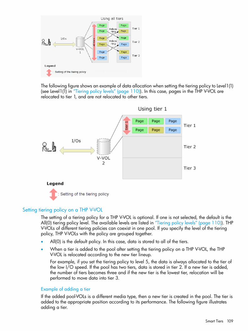
The following figure shows an example of data allocation when setting the tiering policy to Level1(1)(see Level1(1) in “Tiering policy levels” (page 110)). In this case, pages in the THP V-VOL arerelocated to tier 1, and are not relocated to other tiers.
Setting tiering policy on a THP V-VOLThe setting of a tiering policy for a THP V-VOL is optional. If one is not selected, the default is theAll(0) tiering policy level. The available levels are listed in “Tiering policy levels” (page 110)). THPV-VOLs of different tiering policies can coexist in one pool. If you specify the level of the tieringpolicy, THP V-VOLs with the policy are grouped together.
• All(0) is the default policy. In this case, data is stored to all of the tiers.
• When a tier is added to the pool after setting the tiering policy on a THP V-VOL, the THPV-VOL is relocated according to the new tier lineup.For example, if you set the tiering policy to level 5, the data is always allocated to the tier ofthe low I/O speed. If the pool has two tiers, data is stored in tier 2. If a new tier is added,the number of tiers becomes three and if the new tier is the lowest tier, relocation will beperformed to move data into tier 3.
Example of adding a tierIf the added pool-VOLs is a different media type, then a new tier is created in the pool. The tier isadded to the appropriate position according to its performance. The following figure illustratesadding a tier.
Smart Tiers 109

Example of deleting a tierIf a tier no longer has any pool-VOLs when you delete them, the tier is deleted from the pool. Thefollowing figure illustrates deleting a tier.
For more information about tiering policy and groups, see “Tiering policy levels” (page 110).
Tiering policy levels
Note3 tier pool2 tier pool1 tier poolTiering policy
Default Tiering PolicyAll 3 tiersBoth tiersSingle TierAll(0)
Data is located to the Top Tier. Any overflow movesto the next lower tier.
Tier 1Tier 1Same asAll(0)
Level1(1)
Data is located to the Top Tier after Level1(1)assignments are processed. Any overflow moves tothe next lower tier.
Tier 1 andTier 2See note
Same asAll(0)
Same asAll(0)
Level2(2)
Data is located to the Middle Tier. Any overflow movesto the top tier.
Tier 2See note
Same asAll(0)
Same asAll(0)
Level3(3)
Data is located to the Middle Tier after Level3(3)assignments are processed. Any overflow moves tothe next lower tier.
Tier 2 andTier 3See note
Same asAll(0)
Same asAll(0)
Level4(4)
Data is located to the bottom tier. Any overflow movesto the next higher tier.
Tier 3See note
Tier 2Same asAll(0)
Level5(5)
Dependson usersetting
Dependson usersetting
Same asAll(0)
From Level6(6) toLevel31(31)
For example:If additional capacity is added to the pool and the capacity defines a new Tier 1 or new Tier 2, then the THP VOLswith a Level 5(5) assignment will not physically move but Level 5(5) will be associated with Tier 3.If additional capacity is added to the pool and the capacity defines a new Tier 3, the THP VOLs with a Level 5(5)assignment will physically move to the new Tier 3 and Level 5(5) will be associated with Tier 3.
Viewing the tiering policy in the performance graphYou can view the frequency distribution graph of the pool by selecting either the level of the tieringpolicy or the entire pool on the performance graph in the View Tier Properties window.
110 Configuring thin provisioning

The following table shows how tiering policy is shown in the performance graph. How the graphappears depends on the number of tiers set in a pool and tiering policy level selected when viewingthe performance graph.
V-VOL displayed in the performance graphTiering policy selectedwith performancegraph
In the performance graph, you can display a frequency distribution of a THP V-VOL, set toall tiers.
All(0)
In the performance graph, you can display the frequency distribution of a THP V-VOL set tolevel 1.
Level 1(1)
In the performance graph, you can display the frequency distribution of a THP V-VOL set tolevel 2.
Level 2(2)
In the performance graph, you can display the frequency distribution of a THP V-VOL set tolevel 3.
Level 3(3)
In the performance graph, you can display the frequency distribution of a THP V-VOL set tolevel 4.
Level 4(4)
In the performance graph, you can display the frequency distribution of a THP V-VOL set tolevel 5.
Level 5(5)
In the performance graph, you can display the frequency distribution of a THP V-VOL set tocustom policy.
From Level6(6) toLevel31(31)
Smart Tiers 111

Reserving tier capacity when setting a tiering policyIf you set the tiering policy of a THP-VOL, the THP-VOL used capacity and the I/O performancelimitation are reserved from the tier. The reserved limit performance per page is calculated asfollows:The reserved limit performance per page = (The performance limit of the tier) ÷(The number of pages in the tier).A THP-VOL without a tiering policy setting uses the unreserved area in the pool.
Example of reserving tier capacityThe reservation priority depends on the level of tiering policy. The following figure illustrates thereservation priority. Tiers are reserved in order of priority from (1) to (7) in the figure. If the pool-VOLcapacity is deficient when you reserve a tier, the nearest tier of your specified tier is allocated. Ifyou specify two tiers like level 2 or level 4 of the tiering policy, first of all the upper tier is reserved.At this time, if the capacity of the pool-VOL assigned to the upper tier is deficient, the lower tierdefined by the tiering policy is reserved automatically. For example, in case of level 2 in the
112 Configuring thin provisioning

diagram below, tier 1 is reserved first. If the capacity of tier 1 is deficient at this point, tier 2 isreserved automatically. For details, see “Notes on tiering policy settings” (page 114).
Reserved tierTiering policyTier reservationpriority
Tier 1Level1(1)1
Tier 2Level3(3)2
Tier 3Level5(5)3
The custom policy whose number is small is prioritized.From Level6(6) to Level31(31)From 4 to 29Tier 1: From Level6(6) to Level31(31), each of the Tier1Min values are reserved.Tier 2: From Level6(6) to Level31(31), each of valuesthat deducted the total value of Tier1 Max and Tier3Max from 100(%) are reserved.Tier 3: From Level6(6) to Level31(31), each of the Tier3Min values are reserved.
All tiersAll(0)30
Tier 1 and Tier 2Level2(2)
Tier 2 and Tier 3Level4(4)
Tier 1: From Level6(6) to Level31(31), each of the Tier1Max values are reserved.
From Level6(6) to Level31(31)
Tier 3: From Level6(6) to Level31(31), each of the Tier3Max values are reserved.
Smart Tiers 113

Notes on tiering policy settings
• If Auto is set as the execution mode, tier relocation is performed based on the monitoringcycle. Therefore, when the tiering policy setting is changed, tier relocation will automaticallyimplement the tiering policy at the end of the current monitoring cycle. See Example 1 in“Execution mode settings and tiering policy” (page 119).
• If Manual is set as the execution mode, you must manually perform monitoring, issue a monitorstop, and then start relocation (see Example 2, Case 1, in “Execution mode settings and tieringpolicy” (page 119)). If you change the tiering policy settings while obtaining monitoring data,the monitoring data is used for the next tier relocation (see Example 2, Case 2, in “Executionmode settings and tiering policy” (page 119)). Therefore, you do not need to perform newmonitoring.
• If a capacity shortage exists in the tier being set, a message may appear in the View TierProperty window that the page allocation cannot be completed according to the tiering policyspecified for the V-VOL. Should that occur, the page allocation in the entire pool -- includingthe tier that defines the tiering policy -- might not be optimized.
NOTE: The message that page allocation cannot be completed according to the tieringpolicy does not appear when these tiering policies are set:
◦ All(0)
◦ In a 2-tier configuration, Level2(2), Level3(3), or Level4(4) which is equivalent to All(0)
When a capacity shortage exists in a tier, you can revise the setting of the tiering policy orthe configuration of tiers. If the capacity of one tier is fully exhausted, the migrating pagesare assigned to the next tier according to the tiering policy.
◦ Level1(1): When tier 1 is full, the remaining pages are allocated to tier 2. If tier 2 is full,the remaining pages are allocated to tier 3.
◦ Level3(3): When tier 2 is full, the remaining pages are allocated to tier 1. If tier 1 is full,the remaining pages are allocated to tier 3.
◦ Level5(5): When tier 3 is full, the remaining pages are allocated to tier 2. If tier 2 is full,the remaining pages are allocated to tier 1.
◦ Level2(2), Level4(4), and from Level6(6) to Level31(31): When the specified tier is full,the unallocated pages are kept in the prior tier.
• If a performance shortage exists in the tier being set, pages may not be allocated inconformance to the tiering policy specified for the V-VOL. In that case, pages are allocatedaccording to the performance ratio of each tier.As shown in the following table, allocation capacity considerations are based on the tieringpolicy.
Allocation capacity considerationsTiering Policy
Tier range and I/O performanceAll(0), Level2(2), or Level4(4)
Tier rangeLevel1(1), Level3(3), or Level5(5)
First phase: Tier range.From Level6(6) to Level31(31)
114 Configuring thin provisioning

Allocation capacity considerationsTiering Policy
Allocation capacities in each tier.
◦ Tier1: The setting value(%) in Tier1 Min.
◦ Tier2: The value deducted Tier1 Max(%) and Tier3 Max(%) from 100(%).
◦ Tier3: The setting value(%) in Tier3 Min.
Second phase: Tier range and I/O performance.Capacities deducted from the allocated capacities of the first phase fromthe total used capacity, are allocated to each tier.
New page assignment tierIf you set the new page assignment tier value, when a new page is needed by a THP-VOL the pageis taken from the specified tier aligned with the new page assignment tier value. You can set thisfunction by using Remote Web Console. In addition, this function becomes effective just aftersetting. The following table lists setting values:
DescriptionSetting value
The new page is assigned from the higher tier of tiers set in the tiering policy.High
The new page is assigned from the middle tier of tiers set in the tiering policy.Middle
The new page is assigned from the lower tier of tiers set in the tiering policy.Low
The following tables show the tiers to which new pages are preferentially assigned.
NoteWhen specifying LowWhen specifyingMiddle
When specifying HighTiering Policy
If you set Low, tier 2 is givena priority over tier 1.
From tier 2 to 1From tier 1 to 2From tier 1 to 2All
Assignment sequences whenHigh, Middle, and Low aresame.
From tier 1 to 2From tier 1 to 2From tier 1 to 2Level 1
Every assignment sequenceis the same as when All is
From tier 2 to 1From tier 1 to 2From tier 1 to 2Level 2
specified as the tieringpolicy.
Every assignment sequenceis the same as when All is
From tier 2 to 1From tier 1 to 2From tier 1 to 2Level 3
specified as the tieringpolicy.
Every assignment sequenceis the same as when All is
From tier 2 to 1From tier 1 to 2From tier 1 to 2Level 4
specified as the tieringpolicy.
Assignment sequences whenHigh, Middle, and Low aresame.
From tier 2 to 1From tier 2 to 1From tier 2 to 1Level 5
Smart Tiers 115

Order of new page allocationConditionNumber
Same as Level1(1)T1 MIN = 100%1
Same as Level5(5)T1 MAX = 0%2
Same as All(0)T1 MAX > 0%3
NoteWhen specifying LowWhen specifyingMiddle
When specifying HighTiering policy
Specifying High, Middle orLow to the assignmentsequence is effective.
From tier 3, 2, to 1.From tier 2, 3, to 1.From tier 1, 2, to 3.All
Assignment sequences whenHigh, Middle, and Low aresame.
From tier 1, 2, to 3.From tier 1, 2, to 3.From tier 1, 2, to 3.Level 1
If you set Low, tier 2 is givena priority over tier 1.
From tier 2, 1, to 3.From tier 1, 2, to 3.From tier 1, 2, to 3.Level 2
Assignment sequences whenHigh, Middle, and Low aresame.
From the 2, 3, to 1From tier 2, 3, to 1From tier 2, 3, to 1Level 3
If you set Low, tier 3 is givenpriority over tier 2.
From tier 3, 2, to 1From tier 2, 3, to 1From tier 2, 3, to 1Level 4
Assignment sequences whenHigh, Middle, and Low aresame.
From tier 3, 2, to 1From tier 3, 2, to 1From tier 3, 2, to 1Level 5
Order of new page allocationConditionNumber
Same as Level1(1)T1 MIN = 100%1
Same as Level5(5)T3 MIN = 100%2
Same as Level2(2)T1 MAX > 0% and T3 MAX = 0%3
Same as Level3(3)T1 MAX = 0% and T3 MAX = 0%4
Same as Level4(4)T1 MAX = 0% and T3 MAX > 0%5
Same as All(0)T1 MAX > 0% and T3 MAX > 0%6
Relocation priorityIf you use the relocation priority function, you can set the selection priority of a THP V-VOL whenperforming relocation. With this setting, a prioritized THP V-VOL can be relocated earlier duringa relocation cycle. You can set this function by using Remote Web Console. The function is activatedafter the monitoring data is collected.
• If no relocation priority is set for all THP V-VOLs, the general order of THP V-VOL selection isto select the next THP V-VOL in LDEV number order after the last THP V-VOL that fully performedrelocation. This selection order persists across relocation cycles.
• If one or more THP V-VOLs is assigned a relocation priority, the prioritized THP V-VOLs areoperated upon in the early portion of the relocation cycle, before others in the general orderof THP V-VOL selection.
• If V-VOL is not given priority for relocation:For example, if LDEVs of LDEV IDs with LDEV#1, LDEV#2, LDEV#3, LDEV#4, and LDEV#5 arenot given priority for relocation, LDEVs are relocated with the following sequences. In this
116 Configuring thin provisioning

example, three LDEVs are relocated in each period, but the number of LDEVs to relocate maychange by the relocation cycle or the data size.
Relocatingsequence ofLDEV#5 in eachcycle
Relocatingsequence ofLDEV#4 in eachcycle
Relocatingsequence ofLDEV#3 in eachcycle
Relocatingsequence ofLDEV#2 in eachcycle
Relocatingsequence ofLDEV#1 in eachcycle
Relocating cycle
UnperformedUnperformed3rd2nd1stT1
2nd1stUnperformedUnperformed3rdT2
Unperformed3rd2nd1stUnperformedT3
1stUnperformedUnperformed3rd2ndT4
• If V-VOL is given priority for relocation:For example, if LDEVs of LDEV IDs with LDEV#3 and LDEV#4 are set priority for relocationfrom LDEV#1 to LDEV#5, LDEVs are relocated with the following sequences. In this example,three LDEVs are relocated in each period, but the number of LDEVs to relocate may changeby the relocation cycle or data size.
Relocatingsequence ofLDEV#5 in eachcycle
Relocatingsequence ofLDEV#4 in eachcycle
Relocatingsequence ofLDEV#3 in eachcycle
Relocatingsequence ofLDEV#2 in eachcycle
Relocatingsequence ofLDEV#1 in eachcycle
Relocating cycle
Unperformed2nd1stUnperformed3rdT1
Unperformed2nd1st3rdUnperformedT2
3rd2nd1stUnperformedUnperformedT3
Unperformed2nd1stUnperformed3rdT4
Assignment tier when pool-VOLs are deletedWhen you delete pool-VOLs, the pages allocated to the pool-VOLs are moved to other pool-VOLs.The following table shows the tier numbers to which pages are allocated before and after pool-VOLsare deleted. This operation does not depend on the tiering policy or the settings of newly assignedtiers. Relocate tiers after deleting pool-VOLs.The following table describes page allocation in a 3-tier configuration.
DescriptionOrder in which pages areallocated to tiers
Tier of deleted pool-VOLs
If there is free space in Tier 1, pages areallocated to Tier 1.
Tier 1, Tier 2, and Tier 3Tier 1
If there is no free space in Tier 1, pages areallocated to Tier 2.If there is no free space in Tier 1 and Tier 2,pages are allocated to Tier 3.
If there is free space in Tier 2, the pages areallocated to Tier 2.
Tier 2, Tier 1, and Tier 3Tier 2
If there is no free space in Tier 2, pages areallocated to Tier 1.
Smart Tiers 117

DescriptionOrder in which pages areallocated to tiers
Tier of deleted pool-VOLs
If there is no free space in Tier 1 and Tier 2,pages are allocated to Tier 3.
If there is free space in Tier 3, pages areallocated to Tier 3.
Tier 3, Tier 2, and Tier 1Tier 3
If there is no free space in Tier 3, pages areallocated to Tier 2.If there is no free space in Tier 2 and Tier 3,pages are allocated to Tier 1.
The following table describes page allocation in a 2-tier configuration.
DescriptionOrder in which pages areallocated to tiers
Tier of deleted pool-VOLs
If there is free space in Tier 1, pages areallocated to Tier 1.
Tier 1 and Tier 2Tier 1
If there is no free space in Tier 1, pages areallocated to Tier 2.
If there is free space in Tier 2, pages areallocated to Tier 2.
Tier 2 and Tier 1Tier 2
If there is no free space in Tier 2, pages areallocated to Tier 1.
Formatted pool capacityThe formatted pool capacity is the capacity of initialized free space in the pool, not the capacityof all the free space in the pool. The free space of the pool is monitored by a storage system.Space is formatted automatically if needed. You can confirm the formatted pool capacity in theView Pool Management Status window (see “View Pool Management Status window” (page 350)).Dependent on the load of the storage system, the format speed of the free space of the pool isadjusted.New pages are allocated, then initialized, during data write operations to the V-VOL. If a significantnumber of new pages are allocated, initialization might be delayed as a result of conflicts betweendata write and new page initialization processes. Such conflicts could occur, for example, whenyou create a file system of new THP-VOLs from the host. You can initialize the free space of a poolin advance to prevent delays in data write operations.If you want to change the method of performing the function to format the free space of a pool,contact HP Technical Support.
Rebalancing the usage level among pool-VOLsThe usage level among pool-VOLs is rebalanced automatically so that the page usage ratio isaveraged across pool-VOLs and pool-VOL loads are distributed. When rebalancing is done onjobs run for virtual volumes in the same pool, a page is reclaimed if all data on the page is zero.The usage level among pool-VOLs is automatically rebalanced in the following cases:
• Expanding pool capacity
• Shrinking pool capacity
• Reclaiming zero pages
118 Configuring thin provisioning

• Reclaiming zero pages by the page releasing request of a host. For example, when the WriteSame command is performed.
• Performing tier relocations several timesPerformance of the host I/O may decrease due to movement of the existing data. If you do notwant to automate balancing of the usage level of pool-VOLs, call HP Technical Support. You cansee the rebalancing progress of the usage level among pool-VOLs in the View Pool ManagementStatus window (see “View Pool Management Status window” (page 350)). Thin Provisioningautomatically stops balancing the usage levels among pool-VOLs if the cache memory is notredundant or the pool usage rate reaches up to the threshold.
NOTE: If you expand the pool capacity, Thin Provisioning moves data to the added space on aper-page basis. The method for moving the data is determined by the setting of system option mode(SOM) 917 on the P9500 storage system:• SOM 917 ON (default): Rebalance the usage rate among parity groups for which pool-VOLs
are defined.If there are multiple parity groups to which pool-VOLs are defined, Thin Provisioning rebalancesthe usage rate among the parity groups. If a parity group has multiple pool-VOLs, the paritygroup is assumed to be a pool-VOL and Thin Provisioning rebalances the usage rate. For thisreason, the usage rate might not be averaged among pool-VOLs in a parity group. Comparedto rebalancing the usage rate among pool-VOLs, this method reduces the seek time of thehard disk drive during data access.
• SOM 917 OFF: Rebalance the usage rate among pool-VOLs without considering parity groups.SOMs are set on the service processor (SVP) by your HP representative. For a description of theSOMs for the P9500, see the HP XP P9000 Owner Guide. To change the setting of SOM 917,contact HP Technical Support.
Execution mode settings and tiering policyThe follow depicts how tier relocation is performed after changing the tiering policy setting whileAuto execution mode is used.
The following depicts two cases of how tier relocation is performed after changing the tiering policysetting while Manual execution mode is used.
Smart Tiers 119

Changing the tiering policy level on a THP V-VOL1. In the Remote Web Console main window, in the Storage Systems tree, select Logical Devices.
The following is another way to select LDEVs.1. In the Remote Web Console main window, in the Storage Systems tree, select Pool.2. Select the pool associated with the THP V-VOL that has the tiering policy level you want
to change.3. Click the Virtual Volumes tab.
2. From the table, select the row with the THP V-VOL that has the tiering policy level you wantto change.To select consecutive rows, highlight all of the rows to be selected and press the Shift key. Toselect separate rows, click each row while pressing the Ctrl key.
3. Click More Actions, and then select Edit LDEVs.4. In the Edit LDEVs window, select Tiering Policy, and select the tiering policy.5. Click Finish.6. In the Confirm window, confirm the settings, in Task Name type a unique name for this task
or accept the default, and then click Apply.If Go to tasks window for status is checked, the Tasks window opens.
120 Configuring thin provisioning
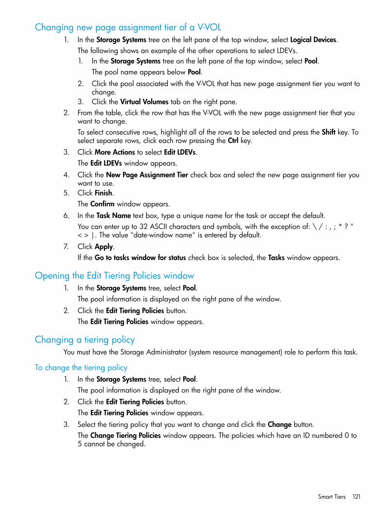
Changing new page assignment tier of a V-VOL1. In the Storage Systems tree on the left pane of the top window, select Logical Devices.
The following shows an example of the other operations to select LDEVs.1. In the Storage Systems tree on the left pane of the top window, select Pool.
The pool name appears below Pool.2. Click the pool associated with the V-VOL that has new page assignment tier you want to
change.3. Click the Virtual Volumes tab on the right pane.
2. From the table, click the row that has the V-VOL with the new page assignment tier that youwant to change.To select consecutive rows, highlight all of the rows to be selected and press the Shift key. Toselect separate rows, click each row pressing the Ctrl key.
3. Click More Actions to select Edit LDEVs.The Edit LDEVs window appears.
4. Click the New Page Assignment Tier check box and select the new page assignment tier youwant to use.
5. Click Finish.The Confirm window appears.
6. In the Task Name text box, type a unique name for the task or accept the default.You can enter up to 32 ASCII characters and symbols, with the exception of: \ / : , ; * ? "< > |. The value "date-window name" is entered by default.
7. Click Apply.If the Go to tasks window for status check box is selected, the Tasks window appears.
Opening the Edit Tiering Policies window1. In the Storage Systems tree, select Pool.
The pool information is displayed on the right pane of the window.2. Click the Edit Tiering Policies button.
The Edit Tiering Policies window appears.
Changing a tiering policyYou must have the Storage Administrator (system resource management) role to perform this task.
To change the tiering policy1. In the Storage Systems tree, select Pool.
The pool information is displayed on the right pane of the window.2. Click the Edit Tiering Policies button.
The Edit Tiering Policies window appears.3. Select the tiering policy that you want to change and click the Change button.
The Change Tiering Policies window appears. The policies which have an ID numbered 0 to5 cannot be changed.
Smart Tiers 121

4. Change the tiering policy, and click OK .After clicking OK, the Edit Tiering Policies window appears again. Note that each tieringpolicy value is needed in order to meet the conditions described in the following table.
ExplanationItem
One of these conditions must be met:Tier1 MaxEqual to Tier1 MinBigger than Tier1 Min
One of these conditions must be met:Tier1 Min*Equal to Tier1 MaxSmaller than Tier1 Max
One of these conditions must be met:Tier3 MaxEqual to Tier3 MinBigger than Tier3 Min
One of these conditions must be met:Tier3 Min*Equal to Tier3 MaxSmaller than Tier3 Max
* The sum of Tier1 Min and Tier3 Min must be 100 (%) or less.
5. Click Finish.The Confirm window appears.
6. In the Task Name text box, type a unique name for the task or accept the default.7. Click Apply.
If the Go to tasks window for status check box is selected, the Tasks window appears.
Changing relocation priority setting of a V-VOL1. In the Storage Systems tree on the left pane of the top window, select Logical Devices.
The following is another way to select LDEVs.1. In the Storage Systems tree on the left pane of the top window, select Pool.
The pool name appears below Pool.2. Click the pool associated with the V-VOL that has the relocation priority you want to
change.3. Click the Virtual Volumes tab on the right pane.
2. From the table, click the row that has the V-VOL with the relocation priority you want to change.To select consecutive rows, highlight all of the rows to be selected and press the Shift key. Toselect separate rows, click each row pressing the Ctrl key.
3. Click More Actions to select Edit LDEVs.The Edit LDEVs window appears.
4. Select the Relocation Priority check box and click Default or Prioritize. If you choose Prioritize,LDEV is relocated preferentially.
5. Click Finish.The Confirm window appears.
122 Configuring thin provisioning
6. In the Task Name text box, enter the task name.You can enter up to 32 ASCII characters and symbols, with the exception of: \ / : , ; * ? "< > |. The value "date-window name" is entered by default.
7. Click Apply.If the Go to tasks window for status check box is selected, the Tasks window appears.
Smart Tiers workflowThe following diagram shows the flow of work for a Storage Administrator to set up Smart Tierson the storage system.As shown in the diagram, Remote Web Console and RAID Manager have different workflows.The details about how to set up Smart Tiers using Remote Web Console are covered in subsequenttopics. For details about how to set up Smart Tiers using RAID Manager, see the HP XP P9000RAID Manager Reference Guide and HP XP P9000 RAID Manager User Guide. Use Remote WebConsole to create pools and THP V-VOLs.
Smart Tiers 123
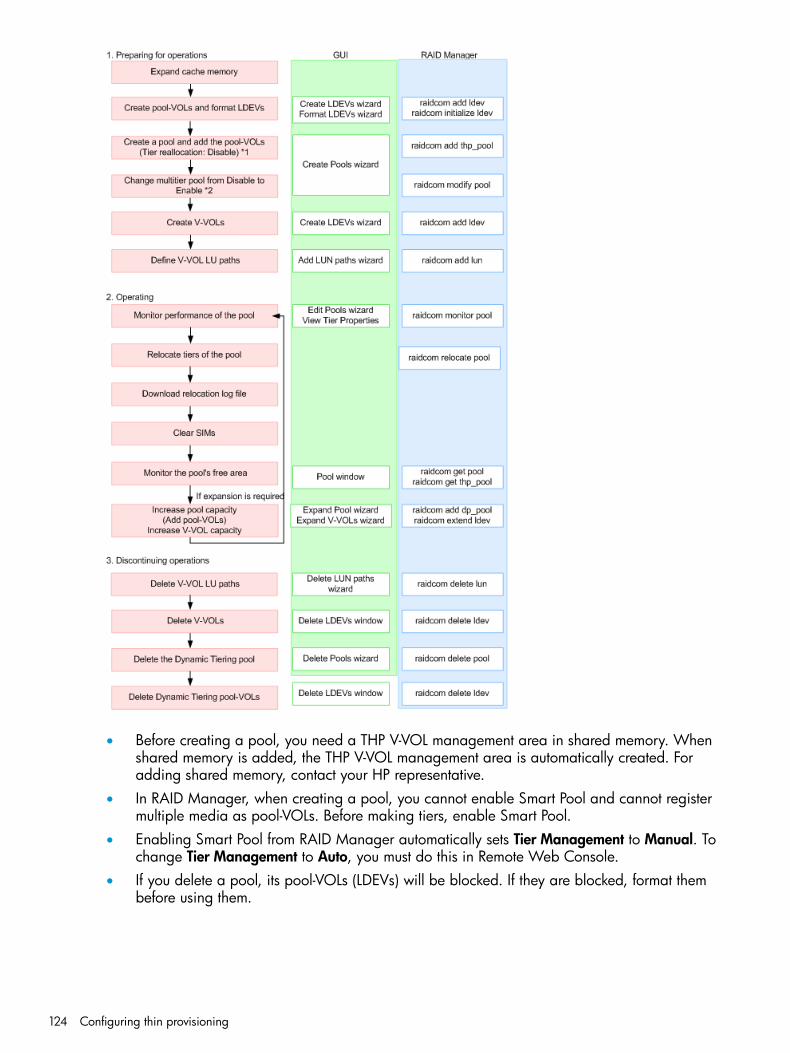
• Before creating a pool, you need a THP V-VOL management area in shared memory. Whenshared memory is added, the THP V-VOL management area is automatically created. Foradding shared memory, contact your HP representative.
• In RAID Manager, when creating a pool, you cannot enable Smart Pool and cannot registermultiple media as pool-VOLs. Before making tiers, enable Smart Pool.
• Enabling Smart Pool from RAID Manager automatically sets Tier Management to Manual. Tochange Tier Management to Auto, you must do this in Remote Web Console.
• If you delete a pool, its pool-VOLs (LDEVs) will be blocked. If they are blocked, format thembefore using them.
124 Configuring thin provisioning

Smart Tiers tasks and parametersThe following topics list the Smart Tiers tasks and parameter settings and indicate whether the taskscan be performed or the parameters can be set in Remote Web Console (GUI) or RAID Manager,or both.
• “Task and parameter settings” (page 125)
• “Display items: Setting parameters” (page 126)
• “Display items: Capacity usage for each tier” (page 127)
• “Display items: Performance monitor statistics” (page 127)
• “Display items: Operation status of performance monitor/relocation” (page 127)
Task and parameter settings
RAIDManager
GUIItemNo.
YYCreateCreateTHP pool1(Setting item) YYPool Name2
YYThreshold3
N1YSmart Pool: Enable/Disable4
NYTier Management: Auto mode5
NYTier Management: Manual mode6
NY3Rate of space for new page assignment7
NYBuffer Space for Tier relocation8
NYCycle Time9
NYMonitoring Period10
NYMonitoring Mode11
NYExternal LDEV Tier Rank12
YYDelete13
YYChange SettingsChange Settings14(Setting item) Y2YPool Name15
YYThreshold16
YYSmart Pool: Enable/Disable17
YYTier Management: Auto to Manual18
NYTier Management: Manual to Auto19
Y3Y3Buffer Space for New page assignment20
YYBuffer Space for Tier relocation21
NYCycle Time22
NYMonitoring Period23
NYMonitoring Mode24
NYExternal LDEV Tier Rank25
YYAdd pool-VOLsTHP pool26
Smart Tiers 125
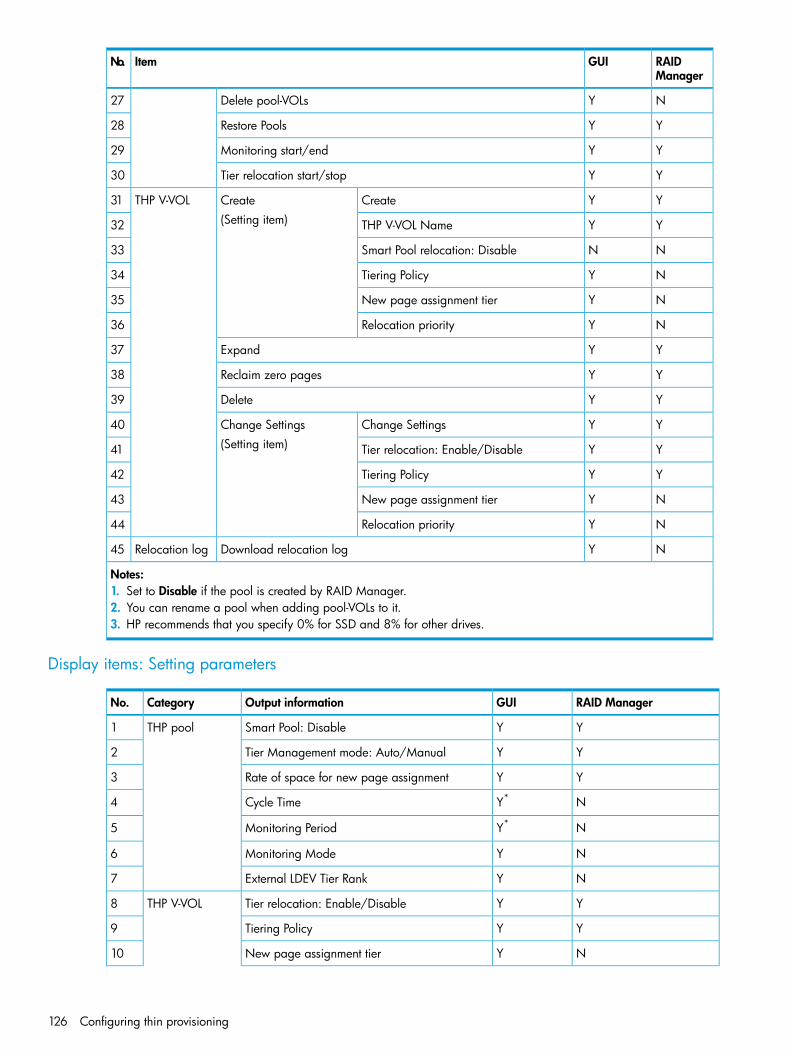
RAIDManager
GUIItemNo.
NYDelete pool-VOLs27
YYRestore Pools28
YYMonitoring start/end29
YYTier relocation start/stop30
YYCreateCreateTHP V-VOL31(Setting item) YYTHP V-VOL Name32
NNSmart Pool relocation: Disable33
NYTiering Policy34
NYNew page assignment tier35
NYRelocation priority36
YYExpand37
YYReclaim zero pages38
YYDelete39
YYChange SettingsChange Settings40(Setting item) YYTier relocation: Enable/Disable41
YYTiering Policy42
NYNew page assignment tier43
NYRelocation priority44
NYDownload relocation logRelocation log45
Notes:1. Set to Disable if the pool is created by RAID Manager.2. You can rename a pool when adding pool-VOLs to it.3. HP recommends that you specify 0% for SSD and 8% for other drives.
Display items: Setting parameters
RAID ManagerGUIOutput informationCategoryNo.
YYSmart Pool: DisableTHP pool1
YYTier Management mode: Auto/Manual2
YYRate of space for new page assignment3
NY*Cycle Time4
NY*Monitoring Period5
NYMonitoring Mode6
NYExternal LDEV Tier Rank7
YYTier relocation: Enable/DisableTHP V-VOL8
YYTiering Policy9
NYNew page assignment tier10
126 Configuring thin provisioning

RAID ManagerGUIOutput informationCategoryNo.
NYRelocation priority11
*You can view this item only in the Auto execution mode.
Display items: Capacity usage for each tier
RAID ManagerGUIOutput informationCategoryNo.
YYCapacity for each tier (Total)THP pool1
YYCapacity for each tier (Usage)2
YYCapacity for each tier (Usage)THP V-VOL3
Display items: Performance monitor statistics
RAID ManagerGUIOutput informationCategoryNo.
NY1Frequency distributionTHP pool1
Y2Y1Tier range2
YYPerformance utilization3
NYMonitoring Period starting time4
NYMonitoring Period ending time5
NYFrequency distributionTHP V-VOL6
NYTier range7
NYMonitoring Period starting time8
NYMonitoring Period ending time9
Notes:1. You can select either each level of the tiering policy or the entire pool. If you set other than All(0), the tier range is
not displayed when you select the entire pool.2. The tier range when the tiering policy All(0) is selected is displayed.
Display items: Operation status of performance monitor/relocation
RAID ManagerGUIOutput informationCategoryNo.
YYMonitor operation status: Stopped/OperatingTHP pool1
YYPerformance monitor information:Valid/Invalid/Calculating
2
YYRelocation status: Relocating/Stopped3
YYRelocation progress: 0 to 100%4
Managing Smart Tiers
Changing pool for Thin Provisioning to pool for Smart Tiers
To change a pool for Thin Provisioning to a pool for Smart Tiers:1. In the Storage Systems tree on the left pane of the top window, select Pool.
Smart Tiers 127

2. From the Pools table on right, click the row of a pool you want to change to the Smart Tierssetting.To select consecutive rows, highlight all of the rows to be selected and press the Shift key. Toselect separate rows, click each row pressing the Ctrl key.
3. Click More Actions and select Edit Pools.The Edit Pools window appears.
4. Check Smart Pool.5. Select Enable from the Smart Pool field.6. To configure Smart Tiers:
1. Select the Tier Management check box.2. From the Tier Management field, select Auto or Manual.
Normally Auto should be set.When you select Auto, monitoring and tier relocation can automatically executed.When you select Manual, monitoring and tier relocation can be executed with the RAIDManager commands or the Pools window of Remote Web Console.When you change the setting of Auto to Manual while monitoring and tier relocation isexecuting, it is cancelled.
3. From the Cycle Time list, select the cycle of performance monitoring and tier relocation.
NOTE:• When you change the Cycle Time while performance monitoring and tier relocation
are being executed, the setting becomes effective for the next cycle after the currentcycle is complete.When you select 24 Hours (default):Monitoring and tier relocation is performed once a day. In the Monitoring Periodfield, specify the time of starting and ending of monitoring in 00:00 to 23:59 (defaultvalue).
• If you specify the starting time later than the ending time, the monitoring continuesuntil the time when you specify as the ending time on the next day. Anytime that isnot in the specified range of the monitor period is not monitored.
• You can view the information gathered by monitoring with Remote Web Consoleand RAID Manager.
• When you change the time range of performance monitoring, the setting becomeseffective from the next cycle after the cycle that is executing is complete.When you select any of 0.5 Hours, 1 Hour, 2 Hours, 4 Hours or 8 Hours:Performance monitoring is performed every duration you selected starting at 00:00.You cannot specify the monitoring period.
4. Select the Monitoring Mode check box.5. From the Monitoring Mode option, select Period Mode or Continuous Mode.
If you want to perform tier relocation using the monitor results from the prior cycle, selectPeriod Mode. If you want to perform tier relocation weighted to the past period monitoringresult, select Continuous Mode.
6. Select the Buffer Space for New page assignment check box.7. In the Buffer Space for New page assignment text box, enter an integer value from 0 to
50 as the percentage (%) to set for each tier.8. Select the Buffer Space for Tier relocation check box.
128 Configuring thin provisioning

9. In the Buffer Space for Tier relocation text box, enter an integer value from 2 to 40 as thepercentage (%) to set for each tier.
7. Click Finish.The Confirm window appears.
8. In the Task Name text box, enter the task name.You can enter up to 32 ASCII characters and symbols in all, except for \ / : , ; * ? " < > |.The value "date-window name" is entered by default.
9. In the Confirm window, click Apply to register the setting in the task.If the Go to tasks window for status check box is selected, the Tasks window appears.
Changing monitoring and tier relocation settingsThis topic describes how to change the following pool settings of Smart Tiers:
• Automatic or manual execution of monitoring and tier relocation
• Cycle time of monitoring and tier relocation
• Time period of monitoring
To change monitoring and tier relocation settings:1. In the Storage Systems tree on the left pane of the top window, select Pool.2. From the Pools table on the right, click the row of the pool with the Smart Tiers setting you
want to change.To select consecutive rows, highlight all of the rows to be selected and press the Shift key. Toselect separate rows, click each row while pressing the Ctrl key.
3. Click More Actions and select Edit Pools.The Edit Pools window appears.
4. Check Tier Management.5. From the Tier Management field, select Auto or Manual.
Normally Auto should be set.When you select Auto, monitoring and tier relocation can automatically executed.When you select Manual, monitoring and tier relocation can be executed with the RAIDManager commands or the Pools window of Remote Web Console.When you change the setting of Auto to Manual while performance monitoring and tierrelocation is executing, it is cancelled and is not performed since then.
6. If Auto is selected from the Cycle Time list, select the cycle of performance monitoring and tierrelocation.
7. Click Finish.The Confirm window appears.
8. In the Task Name text box, enter the task name.You can enter up to 32 ASCII characters and symbols in all, except for \ / : , ; * ? " < > |.The value "date-window name" is entered by default.
9. In the Confirm window, click Apply to register the setting in the task.If the Go to tasks window for status check box is selected, the Tasks window appears.
Smart Tiers 129

Changing monitoring mode setting
To change monitoring mode setting:1. In the Storage Systems tree on the left pane of the top window, select Pool.2. From the Pools table on the right, click the row of the pool with the Smart Tiers setting you
want to change.To select consecutive rows, highlight all of the rows to be selected and press the Shift key. Toselect separate rows, click each row while pressing the Ctrl key.
3. Click More Actions and select Edit Pools.The Edit Pools window appears.
4. Check Monitoring Mode.5. From the Monitoring Mode option, select Period Mode or Continuous Mode.
If you want to perform tier relocation using the monitor results from the prior cycle, selectPeriod Mode. If you want to perform tier relocation weighted to the past period monitoringresult, select Continuous Mode.
6. Click Finish.The Confirm window appears.
7. In the Task Name text box, enter the task name.You can enter up to 32 ASCII characters and symbols in all, except for \ / : , ; * ? " < > |.The value "date-window name" is entered by default.
8. In the Confirm window, click Apply to register the setting in the task.If the Go to tasks window for status check box is selected, the Tasks window appears.
Changing buffer space for new page assignment setting
To change buffer space for new page assignment setting:1. In the Storage Systems tree on the left pane of the top window, select Pool.2. From the Pools table on the right, click the row of a pool with the Smart Tiers setting you want
to change.To select consecutive rows, highlight all of the rows to be selected and press the Shift key. Toselect separate rows, click each row while pressing the Ctrl key.
3. Click More Actions and select Edit Pools.The Edit Pools window appears.
4. Select the Buffer Space for New page assignment check box.5. In the Buffer Space for New page assignment text box, enter an integer value from 0 to 50
as the percentage (%) to set for each tier.6. Click Finish.
The Confirm window appears.7. In the Task Name text box, enter the task name.
You can enter up to 32 ASCII characters and symbols in all, except for \ / : , ; * ? " < > |.The value "date-window name" is entered by default.
8. In the Confirm window, click Apply to register the setting in the task.If the Go to tasks window for status check box is selected, the Tasks window appears.
130 Configuring thin provisioning

Changing buffer space for tier relocation setting
To change buffer space for tier relocation setting:1. In the Storage Systems tree on the left pane of the top window, select Pool.2. From the Pools table on the right, click the row of a pool with the Smart Tiers setting you want
to change.To select consecutive rows, highlight all of the rows to be selected and press the Shift key. Toselect separate rows, click each row while pressing the Ctrl key.
3. Click More Actions and select Edit Pools.The Edit Pools window appears.
4. Select the Buffer Space for Tier relocation check box.5. In the Buffer Space for Tier relocation text box, enter an integer value from 2 to 40 as the
percentage (%) to set for each tier.6. Click Finish.
The Confirm window appears.7. In the Task Name text box, enter the task name.
You can enter up to 32 ASCII characters and symbols in all, except for \ / : , ; * ? " < > |.The value "date-window name" is entered by default.
8. In the Confirm window, click Apply to register the setting in the task.If the Go to tasks window for status check box is selected, the Tasks window appears.
Viewing pool tier information1. In the Remote Web Console main window, in the Storage Systems tree, select Pool.2. From the Pool list, select a pool for which you want to view the information.3. Click More Actions, and then select View Tier Properties.
The View Tier Properties window opens.
Viewing THP V-VOL tier information1. In the Remote Web Console main window, in the Storage Systems tree, select Pool.2. From the Pool list, select a pool associated with the THP V-VOL for which you want to view
the information.3. Click the Virtual Volumes tab.4. From the Virtual Volumes table, select the THP V-VOL for which you want to view the
information.5. Click More Actions, and then select View Tier Properties.
The View Tier Properties window opens.
Changing a pool for Smart Tiers to a pool for Thin ProvisioningYou can change a Smart Tiers pool to a Thin Provisioning pool. However, you cannot change thepool status of Smart Tiers to disable in the following cases:
• Tier relocation is being executed manually.
• Pool-VOLs are being deleted.
• Zero pages are being reclaimed.1. In the Storage Systems tree on the left pane of the top window, select Pool.
The pool name appears below Pool.
Changing a pool for Smart Tiers to a pool for Thin Provisioning 131

2. Select a pool that is changed from a pool for Smart Tiers to a pool for Thin Provisioning.The pool information appears.
3. Click More Actions to select Edit Pool.The Edit Pool window appears.
4. Check Smart Pool and select Disable from the Smart Pool option.5. Click Finish.
The Confirm window appears.6. In the Task Name text box, enter the task name.
You can enter up to 32 ASCII characters and symbols in all, except for \ / : , ; * ? " < > |.The value "date-window name" is entered by default.
7. In the Confirm window, click Apply to register the setting in the task.If the Go to tasks window for status check box is selected, the Tasks window appears.
Working with pools
About poolsThin Provisioning requires the use of pools. A pool consists of more than one pool-VOL. A storagesystem supports up to 128 pools, each of which can contain up to 1024 pool-VOLs and 63,232THP V-VOLs per pool. The pool for Thin Provisioning or Snapshot cannot be used in conjunctionwith other pools.Snapshot also uses pools. The 128-pool maximum per storage system applies to the total numberof both Snapshot pools, and Thin Provisioning pools, and Smart Tiers pools. The pool for ThinProvisioning or Snapshot or Smart Tiers cannot be used in conjunction with other pools. For moreinformation, see the HP XP P9000 Snapshot User Guide.A pool number must be assigned to a pool. Multiple THP V-VOLs can be related to one pool.The total pool capacity combines the capacity of all the registered Thin Provisioning pool-VOLsassigned to the pool. Pool capacity is calculated using the following formulas:
• capacity of the pool (MB) = total number of pages × 42 - 42004200 in the formula is the management area size of the pool-VOL with System Area.
• total number of pages = Σ(floor(floor(pool-VOL number of blocks ÷ 512) ÷168)) for each pool-VOL
where
• floor( ) means to truncate the part of the formula within the parentheses after the decimal point.
About pool-VOLsPool-VOLs are grouped together to create a pool. When a new pool is created, the availablepool-VOLs are selected in the Select Pool VOLs window and added to the Selected Pool Volumestable. Every pool must have a pool-VOL with System Area.During initial creation of a pool, designate a pool-VOL as the pool-VOL with System Area, selectthe pool-VOL, and click Change Top Pool VOL in the selected pool volumes table.
132 Configuring thin provisioning

When adding a volume to the pool for which Smart Pool is enabled, note the following:
• Up to three different drives types/RPM are allowed between all the pool-VOLs to be added.
• Volumes to be added to the same pool must have the same RAID level across all the samedrive type/RPM pool-VOLs.For example, you cannot add a volume whose drive type/RPM is SAS/15k and whose RAIDlevel is 5 (3D+1P) when a volume whose drive type/RPM is also SAS/15k but whose RAIDlevel is 5 (7D+1P) is already in the pool
• Up to three values are allowed for Drive Type/RPM for the volume.If you increase the pool capacity by adding a pool-VOL, a portion of the existing data in the poolautomatically migrates from an older pool-VOL to the newly added pool-VOL, balancing the usagelevels of all the pool-VOLs. If you do not want to automate balancing of the usage levels ofpool-VOLs, call HP Technical Support for assistance.Thin Provisioning does not automatically balance the usage levels among pool-VOLs if the cachememory is not redundant or if the pool usage reaches up to the threshold.The pool-VOLs contained in a pool can be added or deleted. Removing a pool-VOL does not deletethe pool or any related THP V-VOLs. You must delete all THP V-VOLs related to the pool before thepool can be deleted. When the pool is deleted, all data in the pool is also deleted.
Pool statusThe following table describes the pool status that appears in Remote Web Console. The statusindicates that a SIM code may have been issued that needs to be resolved. See “SIM referencecodes” (page 148)for SIM code details.The THP V-VOL status remains normal even though the pool status may be something other thannormal.
SIM code*ExplanationStatus
NoneNormal status.Normal
If the pool-VOL is blocked, SIM code 627XXXis reported.
A pool-VOL in the pool is blocked.Warning
620XXX , 621XXX, or 626XXXThe pool usage level may exceed a pool threshold.ExceededThreshold
NoneThe pools is being shrunk and the pool-VOLs arebeing deleted.
Shrinking
622XXX or 623XXXThe pool is full or an error occurred in the pool,therefore the pool is blocked.
Blocked
*XXX in the SIM code indicates the hexadecimal pool number.
Creating a poolThe following procedure tells how to create a pool using Remote Web Console. This procedure isfor setting up Thin Provisioning, but optional steps are shown for setting up Smart Tiers if you choseto add tiers to your storage system.Before creating a pool, you must install the proper amount of shared memory, and you must havea V-VOL management area in shared memory. When shared memory is added, the V-VOLmanagement area is automatically created. To add shared memory, contact your HP representative.
Working with pools 133
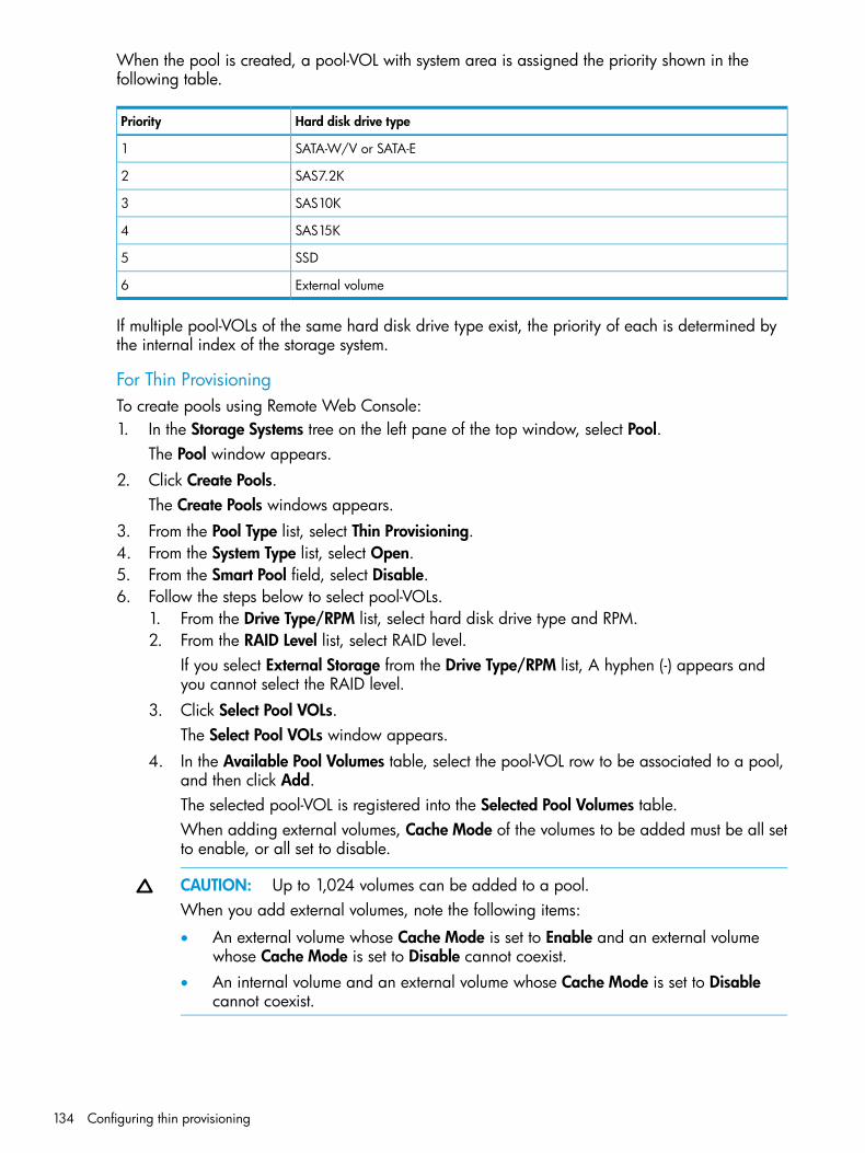
When the pool is created, a pool-VOL with system area is assigned the priority shown in thefollowing table.
Hard disk drive typePriority
SATA-W/V or SATA-E1
SAS7.2K2
SAS10K3
SAS15K4
SSD5
External volume6
If multiple pool-VOLs of the same hard disk drive type exist, the priority of each is determined bythe internal index of the storage system.
For Thin ProvisioningTo create pools using Remote Web Console:1. In the Storage Systems tree on the left pane of the top window, select Pool.
The Pool window appears.2. Click Create Pools.
The Create Pools windows appears.3. From the Pool Type list, select Thin Provisioning.4. From the System Type list, select Open.5. From the Smart Pool field, select Disable.6. Follow the steps below to select pool-VOLs.
1. From the Drive Type/RPM list, select hard disk drive type and RPM.2. From the RAID Level list, select RAID level.
If you select External Storage from the Drive Type/RPM list, A hyphen (-) appears andyou cannot select the RAID level.
3. Click Select Pool VOLs.The Select Pool VOLs window appears.
4. In the Available Pool Volumes table, select the pool-VOL row to be associated to a pool,and then click Add.The selected pool-VOL is registered into the Selected Pool Volumes table.When adding external volumes, Cache Mode of the volumes to be added must be all setto enable, or all set to disable.
CAUTION: Up to 1,024 volumes can be added to a pool.When you add external volumes, note the following items:
• An external volume whose Cache Mode is set to Enable and an external volumewhose Cache Mode is set to Disable cannot coexist.
• An internal volume and an external volume whose Cache Mode is set to Disablecannot coexist.
134 Configuring thin provisioning
NOTE: Perform the following if necessary:• Click Filter to open the menu, specify the filtering, and then Apply.
• Click Select All Pages to select all pool-VOLs in the table. To cancel the selection,click Select All Pages again.
• Click Options to specify the unit of volumes or the number of rows to be displayed.
• To set the tier rank of an external volume to a value other than Middle, select a tierrank from External LDEV Tier Rank, and click Add.
5. Click OK.The information in the Selected Pool Volumes table is applied to Total Selected PoolVolumes and Total Selected Capacity.
7. In the Pool Name text box, enter the pool name as follows:In the Prefix text box, enter the alphanumeric characters, which are fixed characters of thehead of the pool name. The characters are case-sensitive.In the Initial Number text box, type the initial number following the prefix name, which canbe up to 9 digits.You can enter up to 32 characters, including the initial number.
8. Click Options.9. In the Initial Pool ID text box, type the number of the initial pool ID, from 0 to 127.
The smallest available number is displayed in the text box as a default. No number, however,appears in the text box, if no available pool ID exists. When the registered pool ID is entered,the smallest available pool ID is registered automatically among the subsequent pool IDs thatwere entered.
10. In the Subscription Limit text box, enter an integer value from 0 to 65534 as the subscriptionrate (%) for the pool.If it is blank, the subscription rate is set to unlimited.
11. In the Warning Threshold text box, enter an integer value from 1 to 100 as the rate (%) forthe pool. The default value is 70%.
12. In the Depletion Threshold text box, enter an integer value from 1 to 100 as the rate (%) forthe pool. The default value is 80%.Enter a value more than the value of Warning Threshold.
13. Click Add.The created pool is added to the right Selected Pools table. If the invalid values are set, anerror message appears.If even one item that must be set is not entered or selected, you cannot click Add.The items that have to be set include Pool Type, Pool Volume Selection, and Pool Name.If you select a row and click Detail, the Pool Properties window appears. If you select a rowand click Remove, a message appears asking whether you want to remove the selected rowor rows. If you want to remove the row, click OK.
14. Click Next.The Create LDEVs window appears. Go to “Creating V-VOLs” (page 140) to create LDEVs.If Subscription Limit for all the created pool is set to 0%, the Create LDEVs window does notappear.To finish the wizard, click Finish. The Confirm window appears.
Working with pools 135
15. In the Confirm window, click Apply to register the setting in the task.If you select a row and click Detail, the Pool Properties window appears.If the Go to tasks window for status check box is selected, the Tasks window appears.
For Smart TiersTo create pools using Remote Web Console:1. In the Storage Systems tree on the left pane of the top window, select Pool.
The Pool window appears.2. Click Create Pools.
The Create Pools windows appears.3. From the Pool Type list, select Thin Provisioning.4. From the System Type list, select Open.5. From the Smart Pool field, select Enable.
CAUTION: You cannot select Enable if the storage system has only external volumes withthe Cache Mode set to Disable.
6. Follow these steps below to select pool-VOLs:1. In the Drive Type/RPM list, make sure that Mixable is selected.2. From the RAID Level list, make sure that Mixable is selected.3. Click Select Pool VOLs.
The Select Pool VOLs window appears.4. In the Available Pool Volumes table, select the pool-VOL row to be associated to a pool,
and then click Add.The selected pool-VOL is registered into the Selected Pool Volumes table.
CAUTION: Up to 1,024 volumes can be added to a pool.
NOTE: Perform the following if necessary:• Click Filter to open the menu, specify the filtering, and then Apply.
• Click Select All Pages to select all pool-VOLs in the table. To cancel the selection,click Select All Pages again.
• Click Options to specify the unit of volumes or the number of rows to be displayed.
• To set the tier rank of an external volume to a value other than Middle, select a tierrank from External LDEV Tier Rank, and then click Add.
• For a pool, you can add volumes whose Drive Type/RPM settings are the same andwhose RAID Levels are different. For example, you can add the following volumesto the same pool:Volume whose Drive Type/RPM is SAS/15K and whose RAID Level is 5 (3D+1P)Volume whose Drive Type/RPM is SAS/15K and whose RAID Level is 5 (7D+1P)
5. Click OK.The information in the Selected Pool Volumes table is applied to Total Selected PoolVolumes and Total Selected Capacity.
7. In the Pool Name text box, enter the pool name as follows:In the Prefix text box, enter the alphanumeric characters, which are the fixed characters ofthe head of the pool name. The characters are case-sensitive.
136 Configuring thin provisioning

In the Initial Number text box, type the initial number following the prefix name, which canbe up to 9 digits.You can enter up to 32 characters, including the initial number.
8. Click Options.The setting fields following Initial Pool ID appear.
9. In the Initial Pool ID text box, enter the number of the initial pool ID from 0 to 127.The smallest available number is displayed in the text box as a default. No number, however,appears in the text box, if no available pool ID exists. When the registered pool ID is entered,the smallest available pool ID is registered automatically among the subsequent pool IDs thatwere entered.
10. In the Subscription Limit text box, enter an integer value from 0 to 65534 as the subscriptionrate (%).If no figure is entered, the subscription is unlimitedly set.
11. In the Warning Threshold text box, enter an integer value from 1 to 100 as the rate (%) forthe pool. The default value is 70%.
12. In the Depletion Threshold text box, enter an integer value from 1 to 100 as the rate (%) forthe pool. The default value is 80%.Enter a value more than the value of Warning Threshold.
13. Configure Smart Tiers as follows:1. From the Tier Management option, select Auto or Manual.
Normally you select Auto.If you select Auto, performance monitoring and tier relocation are automatically performed.If you select Manual, you can manually perform performance monitoring and tier relocationwith the RAID Manager commands or Remote Web Console.
2. From Cycle Time list, select the cycle of performance monitoring and tier relocation.When you select 24 Hours (default value):Performance monitoring and tier relocation is performed once a day.In the Monitoring Period field, specify the time of starting and ending of performancemonitoring in 00:00 to 23:59 (default value).Take one or more hours between the starting time and the ending time. If you specify thestarting time later than the ending time, the performance monitoring continues until thetime when you specify as the ending time on the next day.You can view the information gathered by performance monitoring with Remote WebConsole and RAID Manager.When you select any of 0.5 Hours, 1 Hour, 2 Hours, 4 Hours or 8 Hours:Performance monitoring is performed every hour you selected starting at 00:00.You cannot specify the time of performance monitoring.Caution: When Auto is set, all the V-VOL pages may not be completed migrating by onecycle. At the next cycle, the last processed V-VOL will start being migrated with the updatedinformation. However, the performance monitoring information is switched.
14. From the Monitoring Mode option, select Period Mode or Continuous Mode.If you perform the tier relocation with the specified cycle or you do not need to specify theMonitoring Mode option, select Period Mode. If you perform the tier relocation weighted tothe past period monitoring result, select Continuous Mode.
Working with pools 137

15. In the Buffer Space for New page assignment text box, enter an integer value from 0 to 50as the percentage (%) to set for each tier.A default value depends on the hard disk drive type of pool-VOL in each tier. The defaultvalue of SSD is 0%. The default value of the type other than SSD is 8%.
16. In the Buffer Space for Tier relocation text box, enter an integer value from 2 to 40 as thepercentage (%) to set for each tier.A default value is 2%.
17. Click Add.The created pool is added to the right Selected Pools table. If invalid values are set, an errormessage appears.The Pool Type, Smart Pool, Pool Volume Selection and Pool Name field must be set. If theserequired items are not registered, you cannot click Add.If you select a row and click Detail, the Pool Properties window appears. If you select a rowand click Remove, a message appears asking whether you want to remove the selected rowor rows. If you want to remove the row, click OK.
18. Click Next.The Create LDEVs window appears. Go to “Creating V-VOLs” (page 140) to create LDEVs.If Subscription Limit for all the created pool is set to 0%, the Create LDEVs window does notappear.To finish the wizard, click Finish. The Confirm window appears.
19. In the Confirm window, click Apply to register the setting in the task.If you select a row and click Detail, the Pool Properties window appears.If the Go to tasks window for status check box is selected, the Tasks window appears.
Notes on pools created with the previous versionsPools created with the previous version of the P9500 microcode may be subject to restrictions inthe current version of the microcode.
Pool-VOLs of RAID 5 and RAID 6 coexisting in the Thin Provisioning poolUsing P9500 microcode 70-02-0x or later, pool-VOLs of RAID 5 and RAID 6 can coexist in theThin Provisioning pool. However, restrictions apply to the following cases.
What cannot be doneUpdated versionVersion that pools werecreated
Pool type
Pool-VOLs of RAID 5 andRAID 6 cannot coexist in thispool.
70-02-0x or laterPrior to 70-02-0xThin Provisioning
This pool cannot be changedto the Thin Provisioning pool.
70-02-0x or laterPrior to 70-02-0xSmart Tiers• Pool-VOLs of RAID 5 and
RAID 6 coexist in thesame pool.
138 Configuring thin provisioning
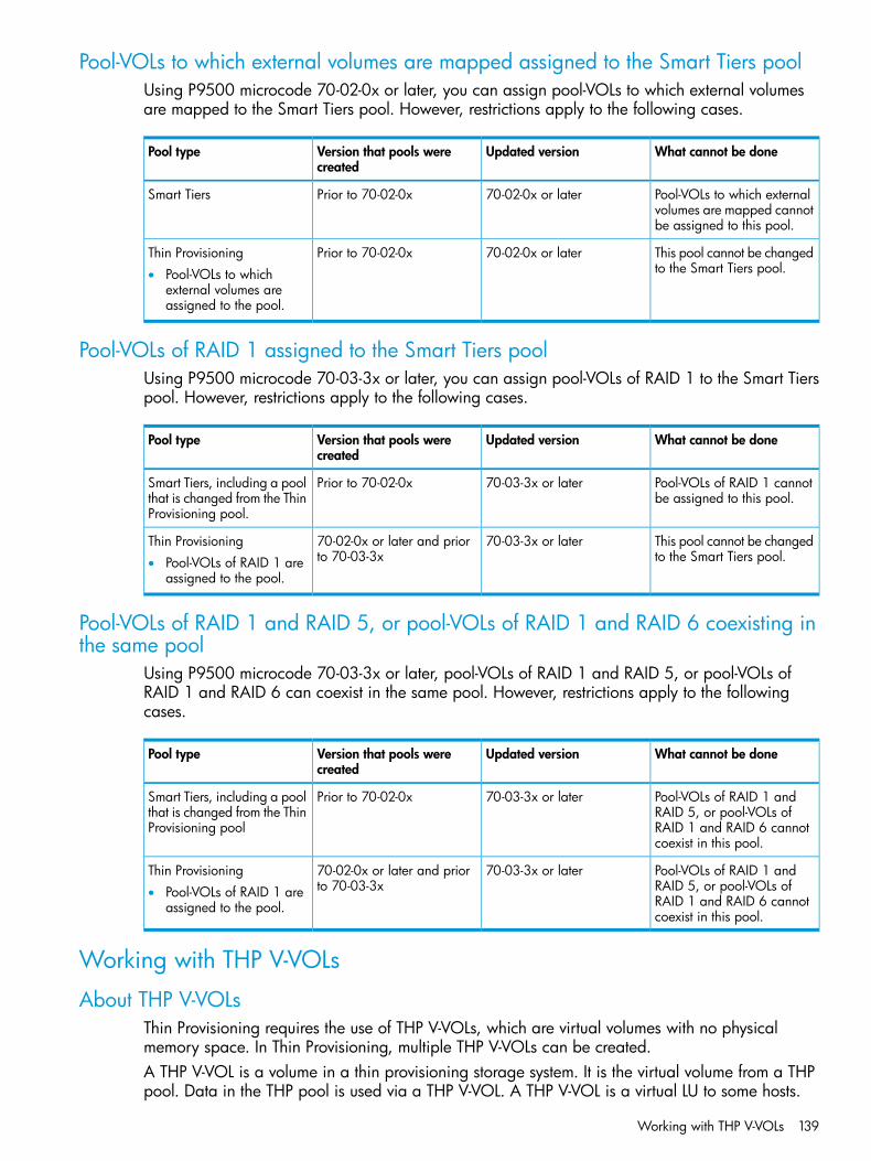
Pool-VOLs to which external volumes are mapped assigned to the Smart Tiers poolUsing P9500 microcode 70-02-0x or later, you can assign pool-VOLs to which external volumesare mapped to the Smart Tiers pool. However, restrictions apply to the following cases.
What cannot be doneUpdated versionVersion that pools werecreated
Pool type
Pool-VOLs to which externalvolumes are mapped cannotbe assigned to this pool.
70-02-0x or laterPrior to 70-02-0xSmart Tiers
This pool cannot be changedto the Smart Tiers pool.
70-02-0x or laterPrior to 70-02-0xThin Provisioning• Pool-VOLs to which
external volumes areassigned to the pool.
Pool-VOLs of RAID 1 assigned to the Smart Tiers poolUsing P9500 microcode 70-03-3x or later, you can assign pool-VOLs of RAID 1 to the Smart Tierspool. However, restrictions apply to the following cases.
What cannot be doneUpdated versionVersion that pools werecreated
Pool type
Pool-VOLs of RAID 1 cannotbe assigned to this pool.
70-03-3x or laterPrior to 70-02-0xSmart Tiers, including a poolthat is changed from the ThinProvisioning pool.
This pool cannot be changedto the Smart Tiers pool.
70-03-3x or later70-02-0x or later and priorto 70-03-3x
Thin Provisioning• Pool-VOLs of RAID 1 are
assigned to the pool.
Pool-VOLs of RAID 1 and RAID 5, or pool-VOLs of RAID 1 and RAID 6 coexisting inthe same pool
Using P9500 microcode 70-03-3x or later, pool-VOLs of RAID 1 and RAID 5, or pool-VOLs ofRAID 1 and RAID 6 can coexist in the same pool. However, restrictions apply to the followingcases.
What cannot be doneUpdated versionVersion that pools werecreated
Pool type
Pool-VOLs of RAID 1 andRAID 5, or pool-VOLs of
70-03-3x or laterPrior to 70-02-0xSmart Tiers, including a poolthat is changed from the ThinProvisioning pool RAID 1 and RAID 6 cannot
coexist in this pool.
Pool-VOLs of RAID 1 andRAID 5, or pool-VOLs of
70-03-3x or later70-02-0x or later and priorto 70-03-3x
Thin Provisioning• Pool-VOLs of RAID 1 are
assigned to the pool. RAID 1 and RAID 6 cannotcoexist in this pool.
Working with THP V-VOLs
About THP V-VOLsThin Provisioning requires the use of THP V-VOLs, which are virtual volumes with no physicalmemory space. In Thin Provisioning, multiple THP V-VOLs can be created.A THP V-VOL is a volume in a thin provisioning storage system. It is the virtual volume from a THPpool. Data in the THP pool is used via a THP V-VOL. A THP V-VOL is a virtual LU to some hosts.
Working with THP V-VOLs 139
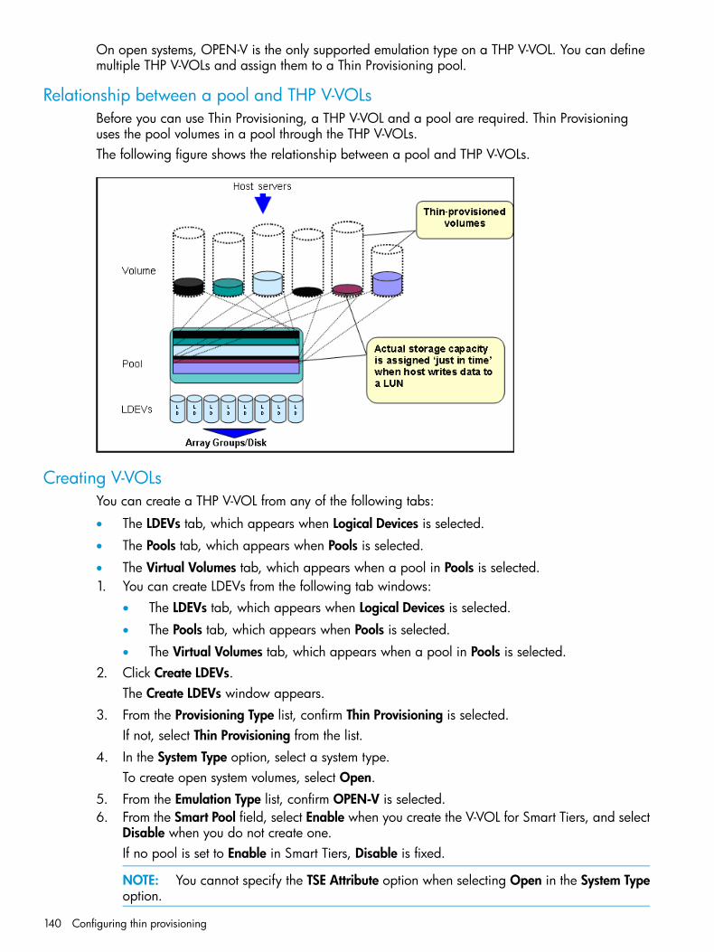
On open systems, OPEN-V is the only supported emulation type on a THP V-VOL. You can definemultiple THP V-VOLs and assign them to a Thin Provisioning pool.
Relationship between a pool and THP V-VOLsBefore you can use Thin Provisioning, a THP V-VOL and a pool are required. Thin Provisioninguses the pool volumes in a pool through the THP V-VOLs.The following figure shows the relationship between a pool and THP V-VOLs.
Creating V-VOLsYou can create a THP V-VOL from any of the following tabs:
• The LDEVs tab, which appears when Logical Devices is selected.
• The Pools tab, which appears when Pools is selected.
• The Virtual Volumes tab, which appears when a pool in Pools is selected.1. You can create LDEVs from the following tab windows:
• The LDEVs tab, which appears when Logical Devices is selected.
• The Pools tab, which appears when Pools is selected.
• The Virtual Volumes tab, which appears when a pool in Pools is selected.2. Click Create LDEVs.
The Create LDEVs window appears.3. From the Provisioning Type list, confirm Thin Provisioning is selected.
If not, select Thin Provisioning from the list.4. In the System Type option, select a system type.
To create open system volumes, select Open.5. From the Emulation Type list, confirm OPEN-V is selected.6. From the Smart Pool field, select Enable when you create the V-VOL for Smart Tiers, and select
Disable when you do not create one.If no pool is set to Enable in Smart Tiers, Disable is fixed.
NOTE: You cannot specify the TSE Attribute option when selecting Open in the System Typeoption.
140 Configuring thin provisioning
7. Select the pool according to the following steps.1. From the Drive Type/RPM list in Pool Selection, select the hard disk drive type and RPM.2. From the RAID level list, select the RAID level.3. Click Select Pool.
The Select Pool window appears.4. In the Available Pools table, select a pool.
NOTE: You can specify a pool when creating THP-VOLs if the pool has a status of oneof the following:• Normal status
• Exceeded Threshold status
• In progress of pool capacity shrinkingYou can select only one pool. When Enable is selected in step 6, the Smart Tiers-poolsappear, and when Disable is selected, only the non-Smart Tiers-pools appear.Perform the following if necessary:
• Click Filter to open the menu, specify the filtering, and then Apply.
• Click Options to specify the units of pools or the number of rows to be displayed.
5. Click OK.The Select Pool window closes. The selected pool name appears in Selected Pool Name(ID), and the total capacity of the selected pool appears in Selected Pool Capacity.
8. In the LDEV Capacity text box, enter the THP-VOL capacity to be created.You can enter the capacity within the range of figures displayed below the text box. You canenter the number with 2 digits after decimal point. You can change the capacity unit from thelist.
9. In the Number of LDEVs text box, enter the number of LDEVs to be created.You can enter the number of LDEVs within a range of the figures displayed below the textbox.
10. In the LDEV Name text box, enter the THP-VOL name.In the Prefix text box, enter the alphanumeric characters, which are fixed characters of thehead of the THP-VOL name. The characters are case-sensitive.In the Initial Number text box, type the initial number following the prefix name, which canbe up to 9 digits.You can enter up to 32 characters including the initial number.
11. Click Options.12. In the Initial LDEV ID field, make sure that LDEV ID is set.
To confirm the used number and unavailable number, click View LDEV IDs to display the ViewLDEV IDs window.
13. In the Initial SSID text box, type the 4-digit SSID of a hexadecimal number (0004 to FFFE).To confirm the created SSID, click View SSID to display the View SSID windows.
14. From the Cache Partition list, select CLPR.15. From the Processor Blade list, select a processor blade.
Select a processor blade to be used by the LDEVs. If you assign a specific processor blade,select the ID of the processor blade. If you can assign any processor blade, click Auto.
Working with THP V-VOLs 141

16. From the Tiering Policy field, select the tiering policy to be used by the LDEVs. If you assign aspecific tiering policy, select any policy. All(0) is selected by default. You can change a levelfrom Level1(1) to Level5(5) or from Level6(6) to Level31(31). You can specify the functionwhen the Smart Pool is enabled.
17. From the New Page Assignment Tier list, select a new page assignment tier. You can selectfrom levels High, Middle, and Low.You can specify the function when the Smart Pool is enabled.
18. In the Relocation Priority option, select a priority.To relocate the LDEV preferentially, set Prioritize. You can select Default or Prioritize. You canspecify this function when the Smart Pool is enabled.
19. If necessary, change the settings of the V-VOLs.You can change the following settings:
• Editing SSIDClick Edit SSIDs to open the Edit SSIDs window.
• Changing the LDEV settingsClick Change LDEV Settings to open the Change LDEV Settings window.
20. If necessary, delete a row from the Selected LDEVs table.Select a row to be deleted, and then click Remove.
21. Click Add.The created V-VOLs are added to the right Selected LDEVs table. If invalid values are set, anerror message appears.The Provisioning Type, System Type, Emulation Type, Pool Selection, Drive Type/RPM, RAIDLevel, LDEV Capacity, and Number of LDEVs field must be set. If these required items are notregistered, you cannot click Add.
22. Click Finish.The Confirm window appears.To continue the operation for setting the LU path and define LUN, click Next.
23. In the Task Name in the text box, enter the task name.You can enter up to 32 ASCII characters and symbols in all, except for \ / : , ; * ? " < > |."yymmdd-window name" is entered as a default.
24. Click Apply.If the Go to tasks window for status check box is selected, the Tasks window appears.
Editing a THP V-VOL's SSIDBefore registering a THP V-VOL, you may need to edit the THP V-VOL's SSID. The SSID is ahexadecimal value.1. In the Selected LDEVs table in the Create LDEVs window, click Edit SSIDs.
The Edit SSIDs window opens. The SSIDs table shows the SSID existing and to be added.2. If you want to change the SSID, select the appropriate LDEV, and then click Change SSIDs.3. In the Change SSIDs window, type the new SSID in hexadecimal format, and then click OK4. In the Edit SSIDs window, click OK.5. In the Create LDEVs window, click Finish.6. In the Confirm window, confirm the settings, and then click Apply.
If Go to tasks window for status is checked, the Tasks window opens.
142 Configuring thin provisioning

Changing THP V-VOL settingsBefore registering a THP V-VOL, you may need to change the THP V-VOL settings.1. In the Selected LDEVs table in the Create LDEVs window, select an LDEV, and then click Change
LDEV Settings.2. In the Change LDEV Settings window, you can change the setting of LDEV Name, Initial LDEV
ID, or Processor Blade.• If you change LDEV Name, specify the prefix characters and the initial number for this
LDEV.• If you change Initial LDEV ID, specify the number of LDKC, CU, DEV, and Interval. To
check used LDEVs, click View LDEV IDs to confirm the used LDEVs. The View LDEV IDswindow opens.
• If you change Processor Blade, click the list and specify the processor blade ID. If thespecific processor blade is specified, select the processor blade ID. If any processor bladeis specified, click Auto.
3. Change the settings, and then click OK.4. In the Create LDEVs window, click Finish.5. In the Confirm window, click Apply.
The setting is changed.If Go to tasks window for status is checked, the Tasks window opens.
Removing the THP V-VOL to be registeredIf you do not want to register the THP V-VOL, you can remove it from the registering task.1. In the Selected LDEVs table in the Create LDEVs window, select the LDEV, and then click Remove.
A message appears asking whether you want to remove the selected row or rows. If you wantto remove the row, click OK.
2. Click Finish.3. In the Confirm window, click Apply.
The LDEV is removed.If Go to tasks window for status is checked, the Tasks window opens.
Formatting LDEVs in a Windows environmentIn a Windows environment, both Normal Format or Quick Format are commonly used. In thisenvironment, Quick Format consumes less thin provisioning pool capacities than Normal Format.On Windows Server 2008, using Normal Format issues Write commands to the overall volume(for example, overall “D” drive). When Write commands are issued, pages corresponding to theoverall volume are allocated, therefore, pool capacities corresponding to the ones of the overallvolume are consumed. In this case, the thin provisioning advantage of reducing capacities is lost.Quick Format issues Write commands only to management information (for example, indexinformation). Therefore, pages corresponding to the management information areas are allocated,but the capacities are smaller than the ones consumed by Normal Format.
Monitoring capacity and performance
Monitoring pool capacityThe storage system monitors the pool’s free capacity in accordance with threshold values definedwhen you create pools. If the pool capacity reaches the threshold values, warnings are issued asSIMs to Remote Web Console and SNMP traps to the open-systems host. See “Monitoring poolusage levels” (page 144) for more information.
Monitoring capacity and performance 143

You can provision a larger virtual capacity beyond the pool capacity by using THP V-VOLs of ThinProvisioning or Smart Tiers. However, when the pool’s free capacity is depleted, you can loseaccess to THP V-VOLs that require more pool capacity. For example, if the pool usage rate is 100%due to increased write operations, then I/O is not accepted and I/O will be stopped for a THPV-VOL that failed to receive needed pool capacity. Therefore, you should carefully monitor thepool usage or pool free capacity, as well as the level of provisioned virtual capacity.
Protecting data during pool shortagesTo protect data from reading and writing to the THP V-VOL when the pool is full, you can applyaccess attributes to a volume. To do this, you need to enable the use of the Data Retention, byinsuring the license is installed and using system option mode 729. This protection method appliesa Protect attribute to the THP V-VOL to protect volumes against write operations when the pool isfull. See “Assigning an access attribute to a volume” (page 166) for more details.The Protect attribute is applied to the THP V-VOL and is used in conjunction with other HP softwareproducts. When the Protect attribute is applied to the THP V-VOL, Permitted appears in the S-VOLfield and 0 day appears in the Validation field of the Data Retention window. However, when theProtect attribute is added to the THP V-VOL with the S-VOL unacceptable attribute available in DataRetention, Not Permitted appears in the S-VOL field in the Data Retention window.
Monitoring pool usage levelsSeveral tools are available that show both the current pool usage rates and the changes over timefor those usage rates. These tools help you monitor the pool free space and estimate when youwill need to increase the pool capacity by adding pool volumes.In the Remote Web Console the Pool window, use the Virtual Volumes tab to view THP V-VOLusage rates and pool usage rates (see “Pools window after selecting pool (Pools window)” (page 299)and (“Top window when selecting a pool under Pools” (page 304).If you have Command View Advanced Edition Suite, you can monitor THP V-VOL usage and poolusages rates using the time-variable graph.
Monitoring performanceYou can monitor system performance using Performance Monitor (see the HP XP P9000 Performancefor Open and Mainframe Systems User Guide). You can monitor information on pools and THPV-VOLs using RAID Manager (RAID Manager) (see the HP XP P9000 RAID Manager User Guide).The following activities help you to monitor and control performance of the THP V-VOL. Collectingmonitor information and subsequent tuning may increase throughput and the operating rates.
• Collecting monitor information. Collecting the following monitor information helps you determinethe pool load (including the access frequency, the trend of pool usage rates, and the accessload upon data drives) and THP V-VOL load (including the access frequency and the trend ofpool allocation rates). You can then use this monitor information to tune the appropriateallocation.
◦ Access frequency of THP V-VOL, read hit rates, and write hit rates (using PerformanceMonitor)
◦ Usage rates of property groups of pools (using Performance Monitor)
◦ Pool usage and elapsed time of pool usage (using Command View Advanced Edition).
144 Configuring thin provisioning
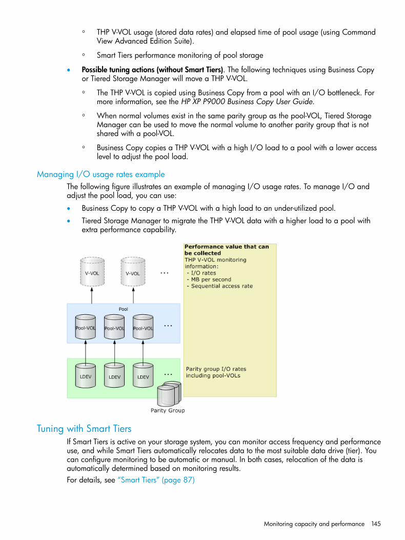
◦ THP V-VOL usage (stored data rates) and elapsed time of pool usage (using CommandView Advanced Edition Suite).
◦ Smart Tiers performance monitoring of pool storage
• Possible tuning actions (without Smart Tiers). The following techniques using Business Copyor Tiered Storage Manager will move a THP V-VOL.
◦ The THP V-VOL is copied using Business Copy from a pool with an I/O bottleneck. Formore information, see the HP XP P9000 Business Copy User Guide.
◦ When normal volumes exist in the same parity group as the pool-VOL, Tiered StorageManager can be used to move the normal volume to another parity group that is notshared with a pool-VOL.
◦ Business Copy copies a THP V-VOL with a high I/O load to a pool with a lower accesslevel to adjust the pool load.
Managing I/O usage rates exampleThe following figure illustrates an example of managing I/O usage rates. To manage I/O andadjust the pool load, you can use:
• Business Copy to copy a THP V-VOL with a high load to an under-utilized pool.
• Tiered Storage Manager to migrate the THP V-VOL data with a higher load to a pool withextra performance capability.
Tuning with Smart TiersIf Smart Tiers is active on your storage system, you can monitor access frequency and performanceuse, and while Smart Tiers automatically relocates data to the most suitable data drive (tier). Youcan configure monitoring to be automatic or manual. In both cases, relocation of the data isautomatically determined based on monitoring results.For details, see “Smart Tiers” (page 87)
Monitoring capacity and performance 145
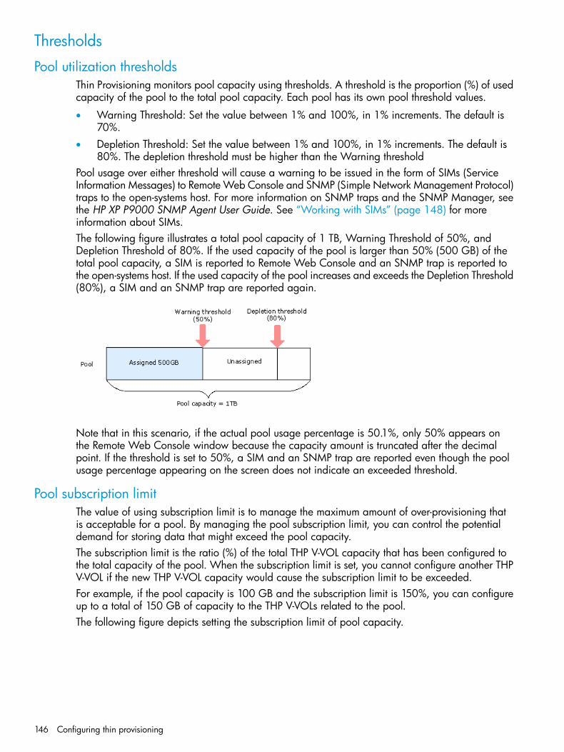
Thresholds
Pool utilization thresholdsThin Provisioning monitors pool capacity using thresholds. A threshold is the proportion (%) of usedcapacity of the pool to the total pool capacity. Each pool has its own pool threshold values.
• Warning Threshold: Set the value between 1% and 100%, in 1% increments. The default is70%.
• Depletion Threshold: Set the value between 1% and 100%, in 1% increments. The default is80%. The depletion threshold must be higher than the Warning threshold
Pool usage over either threshold will cause a warning to be issued in the form of SIMs (ServiceInformation Messages) to Remote Web Console and SNMP (Simple Network Management Protocol)traps to the open-systems host. For more information on SNMP traps and the SNMP Manager, seethe HP XP P9000 SNMP Agent User Guide. See “Working with SIMs” (page 148) for moreinformation about SIMs.The following figure illustrates a total pool capacity of 1 TB, Warning Threshold of 50%, andDepletion Threshold of 80%. If the used capacity of the pool is larger than 50% (500 GB) of thetotal pool capacity, a SIM is reported to Remote Web Console and an SNMP trap is reported tothe open-systems host. If the used capacity of the pool increases and exceeds the Depletion Threshold(80%), a SIM and an SNMP trap are reported again.
Note that in this scenario, if the actual pool usage percentage is 50.1%, only 50% appears onthe Remote Web Console window because the capacity amount is truncated after the decimalpoint. If the threshold is set to 50%, a SIM and an SNMP trap are reported even though the poolusage percentage appearing on the screen does not indicate an exceeded threshold.
Pool subscription limitThe value of using subscription limit is to manage the maximum amount of over-provisioning thatis acceptable for a pool. By managing the pool subscription limit, you can control the potentialdemand for storing data that might exceed the pool capacity.The subscription limit is the ratio (%) of the total THP V-VOL capacity that has been configured tothe total capacity of the pool. When the subscription limit is set, you cannot configure another THPV-VOL if the new THP V-VOL capacity would cause the subscription limit to be exceeded.For example, if the pool capacity is 100 GB and the subscription limit is 150%, you can configureup to a total of 150 GB of capacity to the THP V-VOLs related to the pool.The following figure depicts setting the subscription limit of pool capacity.
146 Configuring thin provisioning
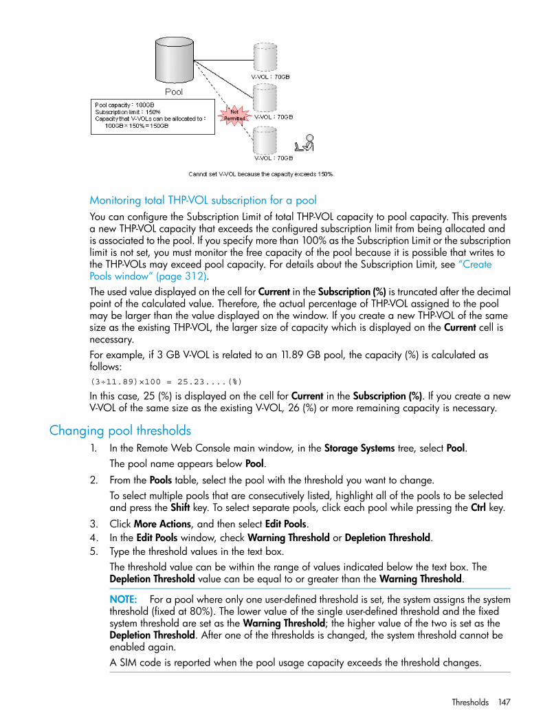
Monitoring total THP-VOL subscription for a poolYou can configure the Subscription Limit of total THP-VOL capacity to pool capacity. This preventsa new THP-VOL capacity that exceeds the configured subscription limit from being allocated andis associated to the pool. If you specify more than 100% as the Subscription Limit or the subscriptionlimit is not set, you must monitor the free capacity of the pool because it is possible that writes tothe THP-VOLs may exceed pool capacity. For details about the Subscription Limit, see “CreatePools window” (page 312).The used value displayed on the cell for Current in the Subscription (%) is truncated after the decimalpoint of the calculated value. Therefore, the actual percentage of THP-VOL assigned to the poolmay be larger than the value displayed on the window. If you create a new THP-VOL of the samesize as the existing THP-VOL, the larger size of capacity which is displayed on the Current cell isnecessary.For example, if 3 GB V-VOL is related to an 11.89 GB pool, the capacity (%) is calculated asfollows:(3÷11.89)×100 = 25.23....(%)
In this case, 25 (%) is displayed on the cell for Current in the Subscription (%). If you create a newV-VOL of the same size as the existing V-VOL, 26 (%) or more remaining capacity is necessary.
Changing pool thresholds1. In the Remote Web Console main window, in the Storage Systems tree, select Pool.
The pool name appears below Pool.2. From the Pools table, select the pool with the threshold you want to change.
To select multiple pools that are consecutively listed, highlight all of the pools to be selectedand press the Shift key. To select separate pools, click each pool while pressing the Ctrl key.
3. Click More Actions, and then select Edit Pools.4. In the Edit Pools window, check Warning Threshold or Depletion Threshold.5. Type the threshold values in the text box.
The threshold value can be within the range of values indicated below the text box. TheDepletion Threshold value can be equal to or greater than the Warning Threshold.
NOTE: For a pool where only one user-defined threshold is set, the system assigns the systemthreshold (fixed at 80%). The lower value of the single user-defined threshold and the fixedsystem threshold are set as the Warning Threshold; the higher value of the two is set as theDepletion Threshold. After one of the thresholds is changed, the system threshold cannot beenabled again.A SIM code is reported when the pool usage capacity exceeds the threshold changes.
Thresholds 147
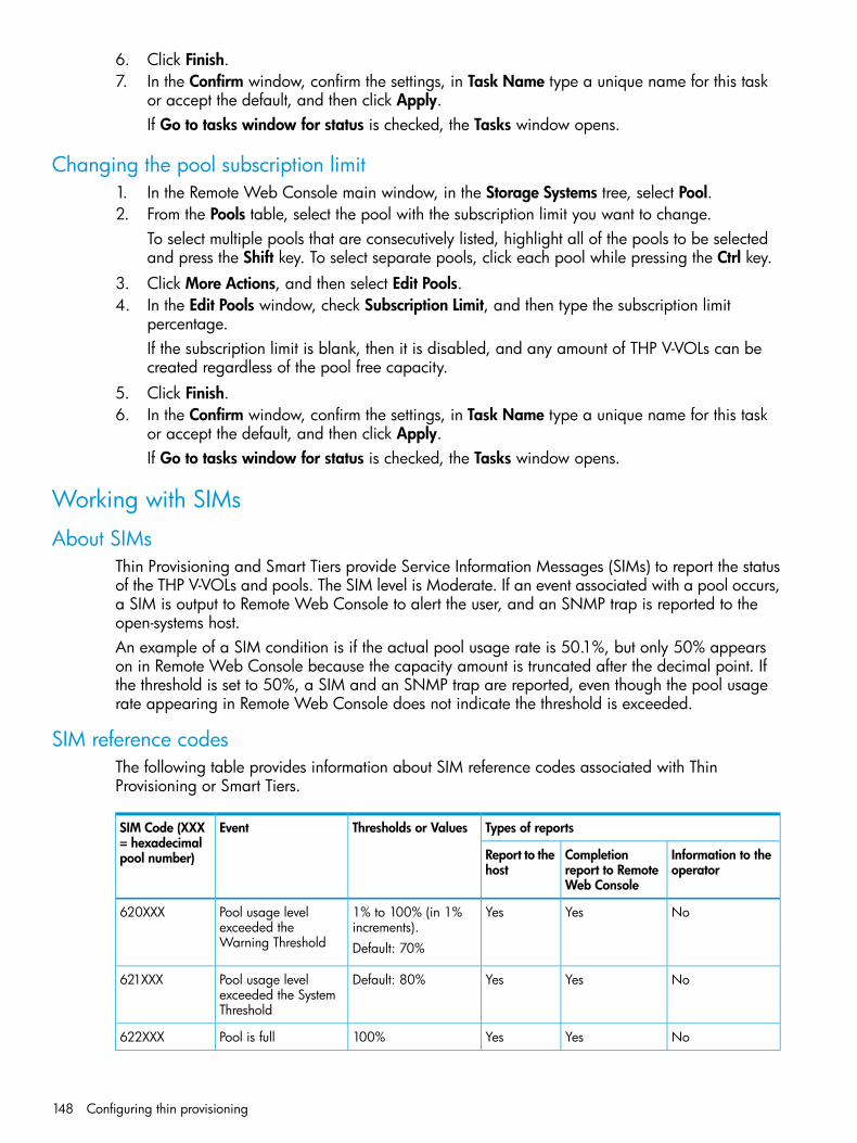
6. Click Finish.7. In the Confirm window, confirm the settings, in Task Name type a unique name for this task
or accept the default, and then click Apply.If Go to tasks window for status is checked, the Tasks window opens.
Changing the pool subscription limit1. In the Remote Web Console main window, in the Storage Systems tree, select Pool.2. From the Pools table, select the pool with the subscription limit you want to change.
To select multiple pools that are consecutively listed, highlight all of the pools to be selectedand press the Shift key. To select separate pools, click each pool while pressing the Ctrl key.
3. Click More Actions, and then select Edit Pools.4. In the Edit Pools window, check Subscription Limit, and then type the subscription limit
percentage.If the subscription limit is blank, then it is disabled, and any amount of THP V-VOLs can becreated regardless of the pool free capacity.
5. Click Finish.6. In the Confirm window, confirm the settings, in Task Name type a unique name for this task
or accept the default, and then click Apply.If Go to tasks window for status is checked, the Tasks window opens.
Working with SIMs
About SIMsThin Provisioning and Smart Tiers provide Service Information Messages (SIMs) to report the statusof the THP V-VOLs and pools. The SIM level is Moderate. If an event associated with a pool occurs,a SIM is output to Remote Web Console to alert the user, and an SNMP trap is reported to theopen-systems host.An example of a SIM condition is if the actual pool usage rate is 50.1%, but only 50% appearson in Remote Web Console because the capacity amount is truncated after the decimal point. Ifthe threshold is set to 50%, a SIM and an SNMP trap are reported, even though the pool usagerate appearing in Remote Web Console does not indicate the threshold is exceeded.
SIM reference codesThe following table provides information about SIM reference codes associated with ThinProvisioning or Smart Tiers.
Types of reportsThresholds or ValuesEventSIM Code (XXX= hexadecimalpool number) Information to the
operatorCompletionreport to RemoteWeb Console
Report to thehost
NoYesYes1% to 100% (in 1%increments).
Pool usage levelexceeded theWarning Threshold
620XXX
Default: 70%
NoYesYesDefault: 80%Pool usage levelexceeded the SystemThreshold
621XXX
NoYesYes100%Pool is full622XXX
148 Configuring thin provisioning

Types of reportsThresholds or ValuesEventSIM Code (XXX= hexadecimalpool number) Information to the
operatorCompletionreport to RemoteWeb Console
Report to thehost
YesNoYesNot applicableError occurred in thepool
623XXX
YesYesYesNot applicableNo space in theshared memory
624000
NoYesYesHighest pool thresholdPool usage levelcontinues to exceed
625000
the highest poolthreshold. SOM 734must be enabled.
NoYesYes1% to 100% (in 1%increments).
Pool usage levelexceeded theDepletion Threshold
626XXX
Default: 80%
YesNoYesNot applicablePool-VOL is blocked627XXX
YesNoYesNot applicableThe Protect attribute ofData Retention Utilityis set.
628000
Automatic completion of a SIMSome SIMs are completed automatically when you resolve the problem that caused the SIM. SOM734 must be enabled for automatic completion of a SIM. Automatic completion of a SIM removesit from the system with no additional manual intervention. After the SIM is automatically completed,the status of the SIM changes to completed in Remote Web Console in the Confirm window.The following SIMs occur when the usage level of the pool exceeds the threshold. They areautomatically completed when you resolve the problem causing the SIM.
• SIMs 620XXX, 621XXX, 625000, and 626XXX are automatically completed if you increasepool capacity by adding pool-VOLs because the condition that caused the SIM removed.
• SIMs are automatically completed in the following cases:
SIM 620XXXIf the THP pool number XXX usage level falls below both of two effective thresholds, SIMis automatically completed.
◦
◦ SIM 621XXXIn the pool of the pool number XXX, if the THP pool usage level falls below both of twoeffective thresholds,SIM is automatically completed.
◦ SIM 625000In all pools in the storage system, if every THP pool’s usage level falls below the higherof two effective thresholds, SIM is automatically completed.
◦ SIM 626XXXIf the THP pool number XXX, usage level falls below both of the two effective thresholds,SIM is automatically completed.
Manually completing a SIMSome SIMs must be manually completed to clear them from the system.
Working with SIMs 149
After the trouble that caused the SIM is solved, you can manually complete the SIM. After manuallycompleting a SIM, the status of the SIM changes to completed. If you complete the SIM before theunderlying cause is solved, the SIM may reoccur.1. Change the status of the pool whose usage level exceeds the threshold to normal. For
information about the solutions when the pool usage level exceeds the threshold, see“Troubleshooting Thin Provisioning” (page 209).
2. In the Remote Web Console main window, in the Storage Systems tree, select Pool.The pool name appears below Pool.
3. Click More Actions, and then select Complete SIMs.ORFrom Pool in the Actions menu, select Complete SIMs.The Complete SIMs window opens.
4. In the Confirm window, confirm the settings, in Task Name type a unique name for this taskor accept the default, and then click Apply.It takes time if many SIMs need to be completed.If Go to tasks window for status is checked, the Tasks window opens.
You can check whether a SIM completes successfully in the Remote Web Console main window.For details, see the HP XP P9000 Remote Web Console User Guide.
Managing pools and THP V-VOLs
Viewing pool information1. In the Remote Web Console main window, in the Storage Systems tree, select Pool.
150 Configuring thin provisioning

2. View the pool information.
For details about the window for pool information, see “Pools window after selecting pool(Pools window)” (page 299) and “Top window when selecting a pool under Pools” (page 304).
Viewing formatted pool capacity1. In the Storage Systems tree on the left pane of the top window, select Pool.2. From the Pools table on the right, click the row of a pool you want to confirm the free pool
capacity.3. Click More Actions to select View Pool Management Status.
The View Pool Management Status window appears.
Following are cases that the free space of the pool is not formatted. In those cases, the free spaceof the pool may not increase:
• Pools other than the selected pool are being formatted.
• The pool usage level reaches up to the warning threshold or the depletion threshold.
• The selected pool is blocked.
• I/O loads to the storage system are high.
• The cache memory is blocked.
• Pool-VOLs in the selected pool are blocked.
• Pool-VOLs which are external volumes in the selected pool are blocked.
Managing pools and THP V-VOLs 151

• Correction access executes to the pool-VOL in the selected pool.
• The format function for the free space of a pool is not operating.If you want to change the method of performing the function to format the free space of apool, contact HP Technical Support.
NOTE: Following are cases that the formatted pool capacity may decrease:• New pages are being allocated.
• LDEV format is being performed on the pool-VOL.
• Correction copy is being executed.
Viewing the progress of rebalancing the usage level among pool-VOLs1. In the Storage Systems tree on the left pane of the top window, select Pool.2. From the Pools table on the right, click the row of a pool you want to confirm the progress of
rebalancing the usage level among pool-VOLs.3. Click More Actions to select View Pool Management Status.
The View Pool Management Status window appears.
Following are cases that the progress ratio may not increase:
• The usage level is being rebalanced among the pool-VOLs in pools other than the selectedpool.
• Tier relocation is performed.
Increasing pool capacityAdding the pool-VOL to the pool created for Thin Provisioning or Smart Tiers increases the poolcapacity. The amount of pool capacity registered in the pool represents the pool capacity. Youneed to check the pool free capacity to determine if additional pool capacity is required. Youcannot increase the pool capacity while it is being shrunk.
Notes on using Thin ProvisioningIf Mixable is set to Enabled, notes on adding the pool-VOL to the pool are as follows:
• The internal volume, and the external volume whose Cache Mode is set to Disable cannotcoexist.
• The external volume whose Cache Mode is set to Enable, and the external volume whose CacheMode is set to Disable cannot coexist.
If Mixable is set to Disabled, notes on adding the pool-VOL to the pool as follows:
• Pool-VOLs of different RAID levels cannot coexist.
• The internal volume and external volume cannot coexist.
Notes on using Smart Tiers
• When pool-VOLs with the available monitoring information are added in a pool, tier relocationis performed. When pool-VOLs with no available monitoring information are added in a pool,the page usage rate is averaged out in a tier.
• If Mixable is set to Enabled, RAID 1 volume and an external volume can be registered in apool. If Mixable is set to Disabled, a RAID 1 volume and an external volume cannot beregistered in a pool.
• If the pool-VOL is the external volume, set Enable for Cache Mode.
• If the pool-VOLs are added, the tier relocation being performed stops.
152 Configuring thin provisioning

Procedure 12 To increase pool capacity1. In the Remote Web Console main window, in the Storage Systems tree, select Pool.2. From the Pools table, select the pool for which you want to increase the capacity. You cannot
increase pool capacity for multiple pools.3. Click Expand Pool.4. In the Expand Pool window, select the pool-VOL.
1. Click Select Pool VOLs.2. In the Select Pool VOLs window, from the Available Pool Volumes table, select the pool-VOL
you want to assign, and then click Add.The selected pool-VOLs are registered in the Selected Pool Volumes table.Up to 1024 volumes can be added including the volumes already in the pool.
NOTE: If necessary, perform the following steps:• From Filter option, select ON to filter the rows.
• Click Select All Pages to select pool-VOLs in the table. To cancel the selection, clickSelect All Pages again.
• Click Options to specify the unit of volumes or the number of rows to be viewed.
• To set the tier rank of an external volume to a value other than Middle, select a tierrank from External LDEV Tier Rank, and then click Add.
• For a pool, you can add volumes whose Drive Type/RPM settings are the same andwhose RAID Levels are different. For example, you can add the following volumesto the same pool:Volume whose Drive Type/RPM is SAS/15K and whose RAID Level is 5 (3D+1P)Volume whose Drive Type/RPM is SAS/15K and whose RAID Level is 5 (7D+1P)
3. Click OK.The Select Pool VOLs window closes. The number of the selected pool volumes appearsin Total Selected Pool Volumes, and the total capacity of the selected pool-VOL appearsin Total Selected Capacity.
5. Click Finish.6. In the Confirm window, confirm the settings, in Task Name type a unique name for this task
or accept the default, and then click Apply.If Go to tasks window for status is checked, the Tasks window opens.
Changing a pool name1. In the Remote Web Console main window, in the Storage Systems tree, select Pool.2. From the Pools table, select the pool with the name you want to change.
To select multiple pools that are consecutively listed, highlight all of the pools to be selectedand press the Shift key. To select separate pools, click each pool while pressing the Ctrl key.
3. Click More Actions, and then select Edit Pools.4. In the Edit Pools window, in Pool Name, specify a name for this pool.
1. In Prefix, type the characters that will become the fixed characters for the beginning ofthe pool name. The characters are case-sensitive.
2. In Initial Number, type the initial number that will follow the prefix name.5. Click Finish.
Managing pools and THP V-VOLs 153

6. In the Confirm window, confirm the settings, in Task Name type a unique name for this taskor accept the default, and then click Apply.If Go to tasks window for status is checked, the Tasks window opens.
Recovering a blocked poolThis procedure is for failure recovery of a blocked pool. Ordinarily, you should not need to usethis procedure. A recovered pool can be used, but the former data is lost.1. In the Remote Web Console main window, in the Storage Systems tree, select Pool.
The pool name appears below Pool.2. From the Pool table, select the pool to be recovered.
To select multiple pools that are consecutively listed, highlight all of the pools to be selectedand press the Shift key. To select separate pools, click each pool while pressing the Ctrl key.
3. Click More Actions, and then select Restore Pools.4. In the Confirm window, confirm the settings, in Task Name type a unique name for this task
or accept the default, and then click Apply.If Go to tasks window for status is checked, the Tasks window opens.
The recovery time for pools varies depending on pool usage or THP V-VOL usage. Allow roughly20 minutes of recovery time for every 100 TB of pool or THP V-VOL usage. Recovery time mayvary depending on the workload of the storage system at the time of recovery.
Decrease pool capacity
About decreasing pool capacityYou can decrease pool capacity by deleting pool-VOLs.When a pool-VOL is removed from a pool, all the used pages in the pool-VOL are moved to otherpool-VOLs.When you delete a pool or decrease the pool capacity, the released pool-VOLs (LDEVs) will beblocked. If they are blocked, format them before using them. If the blocked pool-VOL is an externalvolume, use Normal Format when formatting the volume.You can decrease pool capacity for up to eight tasks at the same time. Do not execute a RAIDManager command to also decrease the capacity of the pool whose capacity is already in theprocess of being decreased.You cannot decrease pool capacity while doing any of the following to a pool.
• Creating the pool.
• Deleting the pool.
• Increasing the pool.
• Decreasing the pool.
• Recovering the pool.
• Stopping decreasing the pool.
• Changing the threshold.
• Reclaiming zero pages.
• Creating THP V-VOLs.
• Increasing THP V-VOL capacity.While the pool capacity is being decreased, if maintenance of cache memory is performed, if thecache memory fails, or if the I/O load to the THP V-VOL related to the pool is high, decreasing
154 Configuring thin provisioning

the pool capacity process might fail. In this case, check the Tasks window to determine whetherprocessing has abnormally ended.If the processing has ended abnormally, restore the cache memory, and then try decreasing thepool capacity again.
NOTE: You cannot perform the following operations on a pool while the pool volume capacityis in the process of shrinking. Wait until shrinking completes or stop the shrinking process.• Expand Pool
• Shrink Pools
• Edit Pools
• Restore Pools
If you delete the pool-VOL with the pool’s system area, the used capacity and the managementarea will move to other pool volumes. If you delete the pool-VOL with system area, a differentsystem area pool-VOL will be assigned automatically according to the priority shown in the followingtable. A pool must include one or more pool-VOLs.
Hard disk drive typePriority
SATA-W/V or SATA-E1
SAS7.2K2
SAS10K3
SAS15K4
SSD5
External volume6
If multiple pool-VOLs of the same hard disk drive type exist, the priority of each is determined byinternal index of the storage system.If pool capacity is decreased soon after creating a pool or adding a pool-VOL, processing maytake a while to complete.
Notes on using Thin ProvisioningYou cannot delete a pool-VOL under these conditions.
• If the pool-VOL is deleted, the used capacity of the pool-VOL exceeds the pool threshold.
• If the pool-VOL is deleted, the subscription rate of the total V-VOL capacity exceeds thesubscription limit.
• If the pool-VOL with system area is deleted, more than 4.2 GB of free space is necessary inthe pool.
Notes on using Smart TiersYou cannot delete a pool-VOL under these conditions.
• If the pool-VOL is deleted, the used capacity of the pool-VOL exceeds the pool threshold.
• If the pool-VOL is deleted, the subscription rate of the total V-VOL capacity exceeds thesubscription limit.
• If the pool-VOL with system area is deleted, more than 4.2 GB of free space is necessary inthe pool.
Managing pools and THP V-VOLs 155

When the pool-VOL is deleted, the pages contained in the deleted pool-VOL transfer to anotherpool-VOL in the same tier. If the used capacity in the tier exceeds Rate of Free Space Newly Allocatedto, the overflowing pages transfer to another tier.When pool-VOLs in the pool are empty, the appropriate tier is deleted.Deleting the pool-VOL stops tier relocation. The process resumes after the pool-VOL is deleted.
Decreasing pool capacity1. In the Remote Web Console main window, in the Storage Systems tree, select Pool.
The pool name appears below Pool.2. Select the pool that contains the pool-VOLs to be deleted.3. From the Pool volumes, select the pool-VOL to be deleted.
To select multiple pool-VOLs that are consecutively listed, highlight all of the pool-VOLs to beselected and press the Shift key. To select separate pool-VOLs, click each pool-VOL whilepressing the Ctrl key.You cannot delete pool-VOLs unless Shrinkable is applied.
4. Click Shrink Pool.The Shrink Pool window opens.The details of Before Shrinking and After Shrinking, including the pool capacity, the usedpool capacity and the free pool capacity, appears in Prediction Result of Shrinking.
5. In the Confirm window, confirm the settings, in Task Name type a unique name for this taskor accept the default, and then click Apply.If Go to tasks window for status is checked, the Tasks window opens.
Stopping the decrease of pool capacity1. In the Remote Web Console main window, in the Storage Systems tree, select Pool.2. From the Pools, select the pool for which you want to stop decreasing pool capacity.
To select multiple pools that are consecutively listed, highlight all of the pools to be selectedand press the Shift key. To select separate pools, click each pool while pressing the Ctrl key.
3. Click Stop Shrinking Pools.The Stop Shrinking Pools window opens.
4. In the Confirm window, confirm the settings, in Task Name type a unique name for this taskor accept the default, and then click Apply.If Go to tasks window for status is checked, the Tasks window opens.
Deleting a tier in a poolTo delete a tier in a pool, you must delete all the pool-VOLs in the tier to be deleted.If you delete a pool, its pool-VOLs (LDEVs) will be blocked. If they are blocked, format them beforeusing them.You cannot delete the pool-VOL when:
• Creating the pool.
• Deleting the pool.
• Increasing the pool capacity.
• Decreasing the pool capacity.
• Restoring the pool.
• Stopping decreasing the pool capacity.
156 Configuring thin provisioning
• Changing the threshold.
• Initializing the pool capacity.
• Changing the external LDEV tier rank
Notes on deleting a tier in a poolYou cannot delete a pool-VOL under these conditions.
• If the pool-VOL is deleted, the used capacity of the pool-VOL exceeds the pool threshold.
• If the pool-VOL is deleted, the subscription rate of the total V-VOL capacity exceeds thesubscription limit.
• If the pool-VOL with system area has less than 4.2 GB of free space. There must be 4.2 GBof free space in the pool in order to delete the pool-VOL with system area.
Deleting the pool-VOL stops the tier relocation. The process resumes after the pool-VOL is deleted.Procedure 13 To delete a tier in a pool1. In the Remote Web Console main window, in the Storage Systems tree, select Pool.
The pool name appears below Pool.2. Select the pool that contains the pool-VOLs to be deleted.
The pool information appears on the right.3. Select the Pool volumes tab and select all the pool-VOLs contained in the tier to be deleted.
To select multiple pool-VOLs that are consecutively listed, highlight all of the pool-VOLs to beselected and press the Shift key. To select separate pool-VOLs, click each pool-VOL whilepressing the Ctrl key.You cannot delete a pool-VOL unless Shrinkable has been applied.
4. Click Shrink Pool.5. In the Shrink Pool window, verify the changes.
The details of Before Shrinking and After Shrinking, including the pool capacity, the usedpool capacity and the free pool capacity, appears in Prediction Result of Shrinking.
6. In the Confirm window, confirm the settings, in Task Name type a unique name for this taskor accept the default, and then click Apply.If Go to tasks window for status is checked, the Tasks window opens.
Deleting a poolWhen you delete a pool, its pool-VOLs (LDEVs) are blocked. If the pool-VOLs are blocked, theymust be formatted before they can be reused. If the blocked pool-VOL is an external volume, selectNormal Format when formatting the volume. You can delete a pool only when all of the THP-VOLshave been deleted.1. In the Storage Systems tree on the left pane of the top window, select Pool.2. From the Pools table on the right, select the pool to be deleted.
You can select multiple pools with the Shift key if the LDEV IDs are listed consecutively. If thepools are not in consecutive order, click the LDEV ID of each pool that you want to deletewhile pressing the Ctrl key.
3. Click More Actions, and then select Delete Pools.The Delete Pools window opens.You cannot delete a pool whose usage is not 0%, or a pool for which THP V-VOLs are assigned.
4. Click Finish.The Confirm window opens.
Managing pools and THP V-VOLs 157
To continue with the shredding operation and delete volume data, click Next. For details aboutthe shredding operation, see the HP XP P9000 Volume Shredder for Open and MainframeSystems User Guide.If the pool is blocked, you might not be able to perform shredding operations.
5. In the Confirm window, confirm the settings, in Task Name type a unique name for this taskor accept the default, and then click Apply.If Go to tasks window for status is checked, the Tasks window opens.
NOTE: When the pool-VOLs of a pool are empty, the appropriate tier is deleted.
Changing external LDEV tier rank
NOTE: When using Smart Tiers, if all pool-VOLs are deleted, the tier is also deleted.
1. In the Storage Systems tree on the left pane of the top window, select Pool.The pool name appears below Pool.
2. From the Pool volumes table in the right pane, select the pool-VOL that has the external LDEVtier rank you want to change.You cannot change the external LDEV tier rank of a pool-VOL if External Volume is not displayedin the Drive Type/RPM column.To select multiple pool-VOLs that are consecutively listed, highlight all of the pool-VOLs to beselected and press the Shift key. To select separate pool-VOLs, click each pool-VOL whilepressing the Ctrl key.
3. Click More Actions and select Edit External LDEV Tier Rank.The Edit External LDEV Tier Rank window appears.
4. From the Selected Pool volumes table, select the pool-VOL with the external LDEV tier rank youwant to change.To select multiple pool-VOLs that are consecutively listed, highlight all of the pool-VOLs to beselected and press the Shift key. To select separate pool-VOLs, click each pool-VOL whilepressing the Ctrl key.
5. Click Change and select the tier rank.6. Click Finish.
The Confirm window appears.7. In the Task Name text box, enter the task name.
You can enter up to 32 ASCII characters and symbols in all, except for \ / : , ; * ? " < > |."date-window name" is entered by default.
8. In the Confirm window, click Apply to register the setting in the task.If the Go to tasks window for status check box is selected, the Tasks window appears.
Increasing THP V-VOL capacity1. In the Remote Web Console main window, in the Storage Systems tree, select Logical Devices.
The following is another way to select LDEVs.1. In the Remote Web Console main window, in the Storage Systems tree, select Pool.
The pool name appears below Pool.2. Select the pool associated with the THP V-VOL that has the capacity that you want to
increase.3. Select the Virtual Volumes tab.
158 Configuring thin provisioning

2. From the table, select the THP V-VOL with the capacity you want to increase.To select multiple THP V-VOLs that are consecutively listed, highlight all of the THP V-VOLs tobe selected and press the Shift key. To select separate THP V-VOLs, click each THP V-VOLwhile pressing the Ctrl key.
3. Click Expand V-VOLs.The Expand V-VOLs window opens. If the THP V-VOL is selected from the LDEV table in theLogical Devices window, click More Actions, and then click Expand V-VOLs.
4. In Capacity, type the capacity amount.You can enter the LDEV capacity to two decimal places within the range of values indicatedbelow the text box.
5. Click Finish.The Confirm window opens.
6. In the Confirm window, confirm the settings, in Task Name type a unique name for this taskor accept the default, and then click Apply.If Go to tasks window for status is checked, the Tasks window opens.
Changing the name of a THP V-VOL1. In the Remote Web Console main window, in the Storage Systems tree, select Logical Devices.
The following is another way to select LDEVs.1. In the Remote Web Console main window, in the Storage Systems tree, select Pool.
The pool name appears below Pool.2. Select the pool associated with the THP V-VOL you want to rename.3. Select the Virtual Volumes tab.
2. From the table, select the THP V-VOL you want to rename.To select multiple THP V-VOLs that are consecutively listed, highlight all of the THP V-VOLs tobe selected and press the Shift key. To select separate THP V-VOLs, click each THP V-VOLwhile pressing the Ctrl key.
3. Click Edit LDEVs.When you selected THP V-VOLs from the Virtual Volumes table, click More Actions, and thenEdit LDEVs.The Edit LDEVs window opens.
4. Check LDEV Name and change the LDEV name, if necessary.1. In Prefix, type the characters that will become the fixed characters for the beginning of
the LDEV name. The characters are case-sensitive.2. In Initial Number, type the initial number that will follow the prefix name.
5. Click Finish.6. In the Confirm window, confirm the settings, in Task Name type a unique name for this task
or accept the default, and then click Apply.If Go to tasks window for status is checked, the Tasks window opens.
About releasing pages in a THP V-VOLReleasing pages in a THP V-VOL frees up pool capacity. When a page in the THP V-VOL containszero data, the free capacity of a pool increases after the pages are released. You can performthe operation to reclaim zero pages on each V-VOL and monitor progress in Remote Web Console.For details, see “View Pool Management Status window” (page 350). If you stop the operation toreclaim zero pages, the zero pages that have been reclaimed cannot be restored.
Managing pools and THP V-VOLs 159
Logically, there is no difference between a page with just zero data and the area of a THP V-VOLwithout a page allotted. Both are effectively identical. However, the former uses pool capacity andthe latter does not.Zero pages can be reclaimed when all the following conditions are satisfied:
• The THP V-VOL is not used in conjunction with another P9500 product which does not supportreclaiming zero pages.See “Using Thin Provisioning or Smart Tiers with other P9500 products” (page 80).
• LDEV formatting is not being performed on the THP V-VOL.
• The THP V-VOL is not blocked.
• The THP V-VOL is associated with a pool.
• The pool associated with the THP V-VOL is not blocked, or is full and blocked.Pages that include file system metadata cannot be reclaimed. Refer to the “Operating system andfile system capacity” (page 79) for a table with the pool capacity consumed by the file system.While releasing pages from a THP V-VOL, performance of the host I/O to the THP V-VOL maytemporarily decrease due to scanning for non-zero data.If you stop an operation to reclaim zero pages in mid-stream, the pages that have been releasedwill remain as free pool capacity.After an operation to reclaim zero pages, Thin Provisioning automatically balances usage levelsamong pool-VOLs in the pool. This rebalancing is performed on all of the THP V-VOLs and pool-VOLsin the pool. If you do not want automatic balancing of the usage levels of pool-VOLs, call HPTechnical Support to change your configuration.Thin Provisioning does not automatically balance the usage levels among pool-VOLs if the cachememory is not redundant or if the pool usage reaches up to the threshold.If all the tracks that belong to a page assigned to a THP V-VOL have no records written, you canreclaim the page and return it to the pool's available capacity.If you have started an operation to reclaim zero pages, and the storage system loses power, theshared memory is disrupted. The operation does not automatically continue after the storage systemrestarts.In the following cases, an operation reclaim zero pages stops and THP V-VOL pages are notreleased.
• LDEV formatting is performed while the operation to reclaim zero pages is in progress.
• The pool-VOL accessed by the target THP V-VOL is blocked.
• The pool associated with the target THP V-VOL is blocked while the operation to reclaim zeropages is in progress.
• Cache memory failure occurs the operation to reclaim zero pages is in progress.
• The THP V-VOL is released when the operation to reclaim zero pages is in progress.
• The initial copy operation between Continuous Access Synchronous pair, Continuous AccessJournal, Business Copy pair is performed on the THP V-VOL in which the zero pages arereclaimed.
Releasing pages in a THP V-VOLYou can reclaim pages in a THP V-VOL to free pool capacity. If a page assigned to a THP V-VOLcontains only zero binary data, you can reclaim the page. Before releasing pages in a THP V-VOL,see “About releasing pages in a THP V-VOL” (page 159)).
160 Configuring thin provisioning

Procedure 14 To release pages in a THP V-VOL1. In the Remote Web Console main window, in the Storage Systems tree, select Logical Devices.
The following is another way to select LDEVs.1. In the Remote Web Console main window, in the Storage Systems tree, select Pool.
The pool name appears below Pool.2. Select the pool associated with the THP V-VOL that has pages you want to release.3. Select the Virtual Volumes tab.
2. From the table, select the THP V-VOL that has pages you want to release.To select multiple THP V-VOLs that are consecutively listed, highlight all of the THP V-VOLs tobe selected and press the Shift key. To select separate THP V-VOLs, click each THP V-VOLwhile pressing the Ctrl key.
3. Click More Actions, and then select Reclaim Zero Pages.The Reclaim Zero Pages window opens.You cannot release pages in a THP V-VOL when the THP V-VOL is not in a normal status orthe THP V-VOL is in the process of reclaiming zero pages.
4. In Task Name type a unique name for this task or accept the default, and then click Apply.If Go to tasks window for status is checked, the Tasks window opens.
After the operation to reclaim zero pages is complete, click Refresh in Remote Web Console toupdate the Page Status. If the Page Status is not immediately updated, wait a while, and then clickRefresh again. Completed status is displayed when no pages can be reclaimed.If you have started the reclaiming zero pages operation, and the storage system is powered offthe reclaiming zero pages operation will not automatically continue after the storage system restarts.In any of the following cases, the reclaiming zero pages will stop, and THP-VOL pages will not bereleased:
• LDEV formatting was performed while reclaiming zero pages.
• The pool-VOL that is being accessed by the target THP-VOL was blocked.
• The pool associated with the target THP-VOL was blocked while reclaiming zero pages.
• Cache memory failure occurred while reclaiming zero pages.
• The THP-VOL was deleted when zero pages were reclaimed.
• The initial copy operation between the Continuous Access Synchronous pair or the ContinuousAccess Journal pair was performed on the THP-VOL in which zero pages were being reclaimed.
Stopping the release of pages in a THP V-VOL1. In the Remote Web Console main window, in the Storage Systems tree, select Logical Devices.
The following is another way to select LDEVs.1. In the Remote Web Console main window, in the Storage Systems tree, select Pool.
The pool name appears below Pool.2. Select the pool associated with the THP V-VOL that has pages you want to release.3. Select the Virtual Volumes tab.
2. From the table, select the THP V-VOL that you want to stop from releasing pages.To select multiple THP V-VOLs that are consecutively listed, highlight all of the THP V-VOLs tobe selected and press the Shift key. To select separate THP V-VOLs, click each THP V-VOLwhile pressing the Ctrl key.
Managing pools and THP V-VOLs 161

3. Click More Actions, and then select Stop Reclaiming Zero Pages.The Stop Reclaiming Zero Pages window opens.You cannot stop releasing the pages in a THP V-VOL where zero pages are not beingreclaimed.
4. In the Confirm window, confirm the settings, in Task Name type a unique name for this taskor accept the default, and then click Apply.If Go to tasks window for status is checked, the Tasks window opens.
Enabling/disabling tier relocation of a THP V-VOLYou can enable or disable tier relocation of individual THP V-VOLs or on all THP V-VOLs.THP V-VOLs on which tier relocation is disabled are excluded from the targets for the tier rangecalculation, and are not reflected in the performance information of pools. If tier relocation isdisabled on all THP V-VOLs in a pool, performance information of a pool is unavailable in theView Tier Properties window.1. In the Remote Web Console main window, in the Storage Systems tree, select Logical Devices.
The following is another way to select LDEVs.1. In the Remote Web Console main window, in the Storage Systems tree, select Pool.2. Select the pool associated with the THP V-VOL for which tier relocation is to be enabled
or disabled.3. Click the Virtual Volumes tab.
2. From the table, select the THP V-VOL for which tier relocation is to be enabled or disabled.To select multiple THP V-VOLs that are consecutively listed, highlight all of the THP V-VOLs tobe selected and press the Shift key. To select separate THP V-VOLs, click each THP V-VOLwhile pressing the Ctrl key.Select multiple THP V-VOLs using the Shift key (if the THP V-VOLs are adjacent), or using theCtrl key (if the THP V-VOLs are not adjacent).
3. Click More Actions, and then select Edit LDEVs.4. In the Edit LDEVs window, check tier relocation and select Enable or Disable.
Enable allows tier relocation to be performed to the THP V-VOL.Disable do not allow tier relocation to be performed on the THP V-VOL in the case of bothautomatic and manual tier relocation.
5. Click Finish.6. In the Confirm window, confirm the settings, in Task Name type a unique name for this task
or accept the default, and then click Apply.If Go to tasks window for status is checked, the Tasks window opens.
Deleting a THP V-VOLYou cannot delete a THP V-VOL if the status is online.1. In the Remote Web Console main window, in the Storage Systems tree, select Logical Devices.
The following is another way to select LDEVs.1. In the Remote Web Console main window, in the Storage Systems tree, select Pool. The
pool name appears below Pool.2. Select the pool associated with the THP V-VOLs to be deleted.3. Click the Virtual Volumes tab.
162 Configuring thin provisioning
2. From the table, select the THP V-VOL to be deleted.To select multiple THP V-VOLs that are consecutively listed, highlight all of the THP V-VOLs tobe selected and press the Shift key. To select separate THP V-VOLs, click each THP V-VOLwhile pressing the Ctrl key.Do the following, if necessary.
• In the Filter option, select ON to filter the rows.
• Click Select All Pages to select all THP V-VOLs in the list.
• Click Options to specify the unit of volumes or the number of rows to view.3. Click More Actions, and then select Delete LDEVs.
The Delete LDEVs window opens.4. In the Confirm window, confirm the settings, in Task Name type a unique name for this task
or accept the default, and then click Apply.If Go to tasks window for status is checked, the Tasks window opens.
Managing pools and THP V-VOLs 163
6 Configuring access attributesAfter provisioning your system, you can assign access attributes to open-system volumes to protectthe volume against read, write, and copy operations and to prevent users from configuring LUpaths and command devices.Data Retention software is required to assign access attributes to volumes.
About access attributesOpen-systems volumes, by default, are subject to read and write operations by open-systems hosts.With open-system volumes in this default condition, data might be damaged or lost if anopen-systems host performs erroneous write operations. In addition, confidential data onopen-systems volumes might be stolen if a malicious operator performs read operations onopen-systems hosts.Therefore, it is recommended that you change the default read and write conditions by assigningan access attribute to each logical volume. Access attributes can be set to read/write, read-only,or protect.By assigning access attributes, you can:
• Protect a volume against both read and write operations of all hosts.
• Protect a volume against write operations of all hosts, but allow read operations.
• Protect a volume against erroneous copy operations, but allow other write operations.
• Prevent other Remote Web Console users from configuring LU paths and command devices.One of the following access attributes can be assigned to each logical volume:
• Read/writeIf a logical volume has the read/write attribute, open-systems hosts can perform both readand write operations on the logical volume.You can use replication software to copy data to logical volumes that have read/write attribute.However, if necessary, you can prevent copying data to logical volumes that have read/writeattribute.All open-systems volumes have the read/write attribute by default.
• Read-onlyIf a logical volume has the read-only access attribute, open-systems hosts can perform readoperations but cannot perform write operations on the logical volume.
• ProtectIf a logical volume has the protect access attribute, open-systems hosts cannot access thelogical volume. Open-systems hosts cannot perform either read nor write operations on thelogical volume.
Access attribute requirementsTo assign access attributes, you need Data Retention software installed on the Remote Web Consolecomputer.
164 Configuring access attributes
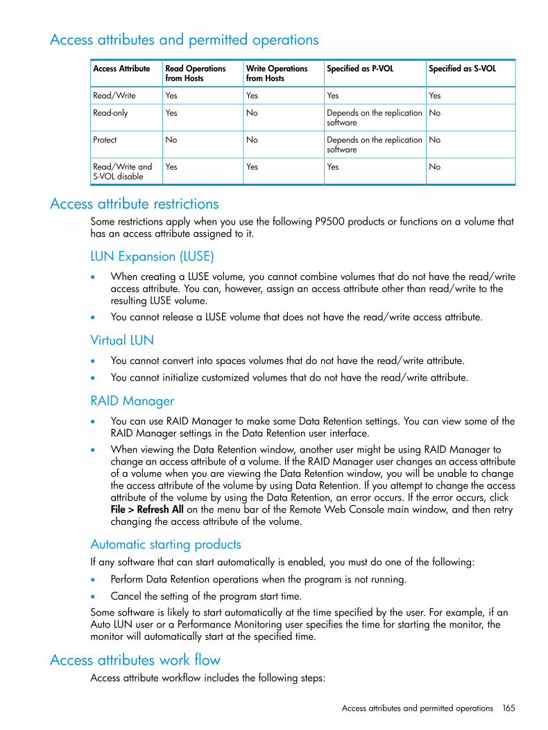
Access attributes and permitted operations
Specified as S-VOLSpecified as P-VOLWrite Operationsfrom Hosts
Read Operationsfrom Hosts
Access Attribute
YesYesYesYesRead/Write
NoDepends on the replicationsoftware
NoYesRead-only
NoDepends on the replicationsoftware
NoNoProtect
NoYesYesYesRead/Write andS-VOL disable
Access attribute restrictionsSome restrictions apply when you use the following P9500 products or functions on a volume thathas an access attribute assigned to it.
LUN Expansion (LUSE)• When creating a LUSE volume, you cannot combine volumes that do not have the read/write
access attribute. You can, however, assign an access attribute other than read/write to theresulting LUSE volume.
• You cannot release a LUSE volume that does not have the read/write access attribute.
Virtual LUN• You cannot convert into spaces volumes that do not have the read/write attribute.
• You cannot initialize customized volumes that do not have the read/write attribute.
RAID Manager• You can use RAID Manager to make some Data Retention settings. You can view some of the
RAID Manager settings in the Data Retention user interface.• When viewing the Data Retention window, another user might be using RAID Manager to
change an access attribute of a volume. If the RAID Manager user changes an access attributeof a volume when you are viewing the Data Retention window, you will be unable to changethe access attribute of the volume by using Data Retention. If you attempt to change the accessattribute of the volume by using the Data Retention, an error occurs. If the error occurs, clickFile > Refresh All on the menu bar of the Remote Web Console main window, and then retrychanging the access attribute of the volume.
Automatic starting productsIf any software that can start automatically is enabled, you must do one of the following:
• Perform Data Retention operations when the program is not running.
• Cancel the setting of the program start time.Some software is likely to start automatically at the time specified by the user. For example, if anAuto LUN user or a Performance Monitoring user specifies the time for starting the monitor, themonitor will automatically start at the specified time.
Access attributes work flowAccess attribute workflow includes the following steps:
Access attributes and permitted operations 165

1. “Changing an access attribute to read-only or protect” (page 166)2. “Changing an access attribute to read/write” (page 168)3. “Enabling or disabling the expiration lock” (page 168)4. “Disabling an S-VOL” (page 169)5. “Reserving volumes” (page 169)
Assigning an access attribute to a volumeIf you want to protect volumes against both read and write operations from hosts, change theaccess attribute to protect. To protect volumes against write operations from hosts and allow readoperations, change the access attribute to read-only. In both ways, if you set the attribute to avolume by Remote Web Console, S-VOL Disable is automatically set to prevent data in a volumefrom being overwritten by replication software. If you use RAID Manager to set the attribute to avolume, you can select whether the S-VOL Disable is set or not. If you set the Protect attribute tothe volume when the Thin Provisioning pool is full, the S-VOL Disable is not set to the volume.After you change an access attribute to read-only or protect, the access attribute cannot be changedto read/write for a certain period of time. You can specify the length of this period (called RetentionTerm) when changing the access attribute to read-only or protect. The retention term can be extendedbut cannot be shortened.During the retention term
• Read-only access can be changed to protect or protect can be changed to read-only.
• If you need to change an access attribute to read/write, you must ask the maintenancepersonnel to do so.
After the retention term is over
• The access attribute can be changed to read/write.
• The access attribute remains read-only or protect until changed back to read/write.
Changing an access attribute to read-only or protectWhen changing an access attribute to read-only or protect, observe the following:
• Do not assign an access attribute to a volume if any job is manipulating data on the volume.If you assign an access attribute to such a volume, the job will possibly end abnormally.
• The emulation type of the volume must be one of the following:OPEN-3, OPEN-8, OPEN-9, OPEN-E, OPEN-K, OPEN-L, OPEN-V
• The volume must not be one of the following:
Volumes that do not exist◦◦ Volumes that are configured as command devices
◦ Continuous Access Synchronous S-VOLs (*)
◦ Continuous Access Journal S-VOLs (*) or journal volumes
◦ Business Copy S-VOLs (*)
◦ Fast Snap S-VOLs (*)
◦ Snapshot S-VOL (*)
◦ Reserved volumes for Auto LUN
◦ Pool volume
166 Configuring access attributes
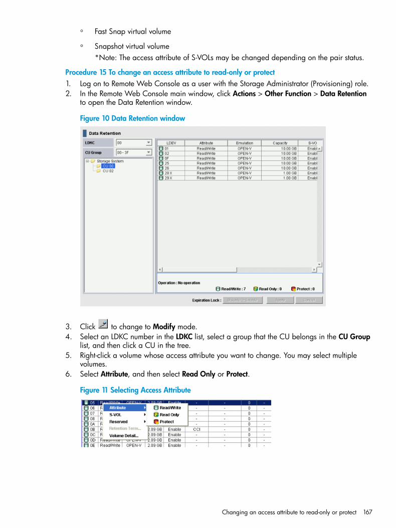
◦ Fast Snap virtual volume
◦ Snapshot virtual volume*Note: The access attribute of S-VOLs may be changed depending on the pair status.
Procedure 15 To change an access attribute to read-only or protect1. Log on to Remote Web Console as a user with the Storage Administrator (Provisioning) role.2. In the Remote Web Console main window, click Actions > Other Function > Data Retention
to open the Data Retention window.
Figure 10 Data Retention window
3. Click to change to Modify mode.4. Select an LDKC number in the LDKC list, select a group that the CU belongs in the CU Group
list, and then click a CU in the tree.5. Right-click a volume whose access attribute you want to change. You may select multiple
volumes.6. Select Attribute, and then select Read Only or Protect.
Figure 11 Selecting Access Attribute
Changing an access attribute to read-only or protect 167

7. In the Term Setting dialog box, specify the retention term. During this period, the accessattribute cannot be changed to read/write. You can enter the number of years and days, orselect Unlimited. The retention term can be extended but cannot be shortened.• years: Specify the number of years within the range of 0 to 60. One year is counted as
365 days, whether the year is a leap year.• days: Specify the number of days within the range of 0 to 21900.For example, if 10 years 5 days or 0 years 3655 days is specified, the access attribute ofthe volume cannot be changed to read/write in the next 3,655 days.
8. Click OK to close the dialog box.9. In the Data Retention window, click Apply to apply the setting.To extend the retention term later, open the Data Retention window, right-click the volume, andthen select Retention Term.
Changing an access attribute to read/writeBefore changing the access attribute from read-only or protect to read/write, considering thefollowing:
• Do not assign an access attribute to a volume if any job is manipulating data on the volume.If you assign an access attribute to such a volume, the job will possibly end abnormally.
• Make sure that the retention term is expired. If expired, the Retention Term column in the DataRetention window shows 0. To change the access attribute to read/write within the retentionterm, contact HP Technical Support.
• Make sure that Expiration Lock indicates Disable -> Enable. If it indicates Enable -> Disable,changing to read/write is restricted by an administrator for some reason. Contact theadministrator of your system to ask if you can change the access attribute. (See “Enabling ordisabling the expiration lock” (page 168))
Procedure 16 To change an access attribute to read/write1. Log on to Remote Web Console as a user assigned to the Storage Administrator (Provisioning)
role.2. In the Remote Web Console main window, click Actions > Other Function > Data Retention
to open the Data Retention window.
3. Click to change to Modify mode.4. Select an LDKC number in the LDKC list, select a group in which the CU belongs in the CU
Group list, and then click a CU in the tree.5. Right-click a volume for which you want to change access attributes. You may select multiple
volumes, select Attribute, and then click Read/Write.6. Click Apply to apply the setting.
Enabling or disabling the expiration lockThe expiration lock provides enhanced volume protection. Enabling the expiration lock ensuresthat read-only volumes and protect volumes cannot be changed to read/write volumes, even afterthe retention term ends. Disabling the expiration lock changes the access attribute to read/writeafter the retention term ends.This setting applies to all volumes in the storage system with the read-only and protect attribute.Procedure 17 To enable the expiration lock1. Log on to Remote Web Console as a user assigned to the Storage Administrator (Provisioning)
role.2. In the Remote Web Console main window, click Actions > Other Function > Data Retention
to open the Data Retention window.
168 Configuring access attributes
3. Click to change to Modify mode.4. In the Data Retention window, verify which button appears beside Expiration Lock.
• If Disable -> Enable appears, go to the next step.
• If Enable -> Disable appears, expiration lock is already enabled. You do not need tofollow the rest of this procedure because attempts to change access attribute to read/writeare already prohibited.
5. Click Disable -> Enable. A confirmation message appears.6. Click OK. The button changes to Enable -> Disable, and then expiration lock is enabled. When
expiration lock is enabled, access attributes of volumes cannot be changed to read/writeeven after the retention term ends.
To disable the expiration lock, click Enable -> Disable. The access attribute can be changed toread/write after the retention term ends.
Disabling an S-VOLAssigning a read-only or protect attribute is one of the ways to prevent data in a volume frombeing overwritten by replication software. Volumes having the read-only or protect attribute arenot only protected against these copy operations, but are also protected against any other formof write operations.To protect a volume only from copy operations, you must ensure that the volume has the read/writeattribute and then assign the S-VOL Disable attribute to the volume. This setting prohibits the volumefrom being used as a secondary volume for copy operations.Procedure 18 To disable an S-VOL1. Log on to Remote Web Console as a user assigned to the Storage Administrator (Provisioning)
role.2. In the Remote Web Console main window, click Actions > Other Function > Data Retention
to open the Data Retention window.
3. Click to change to Modify mode.4. Select an LDKC number in the LDKC list, select a group that the CU belongs in the CU Group
list, and then click a CU in the tree.5. Right-click a volume for which the S-VOL column shows Enable. You may select multiple
volumes.6. Select S-VOL > Disable.7. Click Apply to apply the setting.To use a volume as an S-VOL, ensure that the volume has the read/write attribute and then assignthe S-VOL Enable attribute to the volume.
Reserving volumesBy default, all Remote Web Console users with proper permissions can make LU path settings andcommand device settings. If you perform the following procedure in Remote Web Console, allusers, including yourself, will not be allowed to make LU path settings and command device settingson the specified volume. RAID Manager users can still make LU path settings and command devicesettings on the volume.Procedure 19 To reserve volumes1. Log on to Remote Web Console as a user assigned to the Storage Administrator (Provisioning)
role.2. In the Remote Web Console main window, click Actions > Other Function > Data Retention.
3. Click to change to Modify mode.
Disabling an S-VOL 169

4. In the Data Retention window, select an LDKC number in the LDKC list, select a group that theCU belongs in the CU Group list, and then click a CU in the tree.
5. Select a volume where the Reserved column contains a hyphen. You may select multiplevolumes.
6. Right-click the selected volume or volumes, and then select Reserved > Set.7. Click Apply to apply the setting.To permit Remote Web Console users to make LU path settings and command device settings ona volume, follow the steps above and select Reserved > Release. Then call HP Technical Supportto ask for SVP settings.
170 Configuring access attributes

7 Managing logical volumesAfter provisioning your system, you can begin to manage open-system logical volumes. Managinglogical volumes includes tasks such as configuring hosts and ports, configuring LU paths, settingLUN security on ports, and setting up fibre channel authentication.LUN Manager is required to manage logical volumes.
LUN Manager overview
LUN Manager operationsThe P9500 storage system can be connected to open-system server hosts of different platforms (forexample, UNIX servers and PC servers). To configure a system that includes open-system hosts anda P9500 storage system, use LUN Manager to configure logical volumes and ports.One of the important tasks when configuring logical volumes is to define I/O paths from hosts tological volumes. When paths are defined, the hosts can send commands and data to the logicalvolumes and also can receive data from the logical volumes.After the system begins operating, you might need to modify the system configuration. For example,if hosts or disks are added, you will need to add new I/O paths. You can modify the systemconfiguration with LUN Manager when the system is running. You do not need to restart the systemwhen modifying the system configuration.
Fibre channel operationsAfter open-system hosts and the storage system are physically connected by cables, hubs, and soon, use LUN Manager to establish I/O paths between the hosts and the logical volumes. Thisdefines which host can access which logical volume. Logical volumes that can be accessed byopen-system hosts are referred to as logical units (LUs). The paths between the open-system hostsand the LUs are referred to as LU paths.Before defining LU paths, you must classify server hosts by host groups. For example, if Linux hostsand Windows hosts are connected to the storage system, you must create one host group for theLinux hosts and another host group for the Windows hosts. Then, you must register the host busadapters of the Linux hosts in the Linux host group. You must also register the host bus adapters ofthe Windows hosts in the windows host group.A host group can contain only those hosts that are connected to the same port, and cannot containhosts that are connected to different ports. For example, if two Windows hosts are connected toport 1A and three Windows hosts are connected to port 1B, you cannot register all five Windowshosts in one host group. You must register the first two Windows hosts in one host group, and thenregister the remaining three Windows hosts in another host group.After server hosts are classified into host groups, you associate the host groups with logical volumes.The following figure illustrates LU paths configuration in a fibre channel environment. The figureshows host group hg-lnx associated with three logical volumes (00:00:00, 00:00:01, and00:00:02). LU paths are defined between the two hosts in the hg-lnx group and the three logicalvolumes.
LUN Manager overview 171

You can define paths between a single server host and multiple LUs. The figure shows that eachof the two hosts in the host group hg-lnx can access the three LUs.You can also define paths between multiple server hosts and a single LU. The figure shows thatthe LU identified by the LDKC:CU:LDEV number 00:00:00 is accessible from the two hosts thatbelong to the hg-lnx host group.The figure also shows that the LUs associated with the hg-lnx host group are addressed bynumbers 0000 to 0002. The address number of an LU is referred to as a LUN (logical unit number).When Continuous Access Synchronous and other software manipulates LUs, the software use LUNsto specify the LUs to be manipulated.You can add, change, and delete LU paths when the system is in operation. For example, if newdisks or server hosts are added to your storage system, you can add new LU paths. If an existingserver host is to be replaced, you can delete the LU paths that correspond to the host beforereplacing the host. You do not need to restart the system when you add, change, or delete LUpaths.If a hardware failure (such as a CHA failure) occurs, there is a chance that some LU paths aredisabled and some I/O operations are stopped. To avoid such a situation, you can define alternateLU paths; if one LU path fails, the alternate path takes over the host I/O. For information, see“Defining LU paths” (page 185) and “Defining alternate LU paths” (page 187).
LUN Manager license requirementsUse of LUN Manager on the P9500 storage system requires the following:
• A license key on the Remote Web Console computer for LUN Manager software. For detailsabout the license key or product installation, see the HP XP P9000 Remote Web Console UserGuide.
LUN Manager rules, restrictions, and guidelines
Rules
• In a fibre channel environment, up to 2,048 LU paths can be defined for one host group andup to 2,048 LU paths can be defined for one port.
• Up to 255 host groups can be created for one fibre channel port.
172 Managing logical volumes
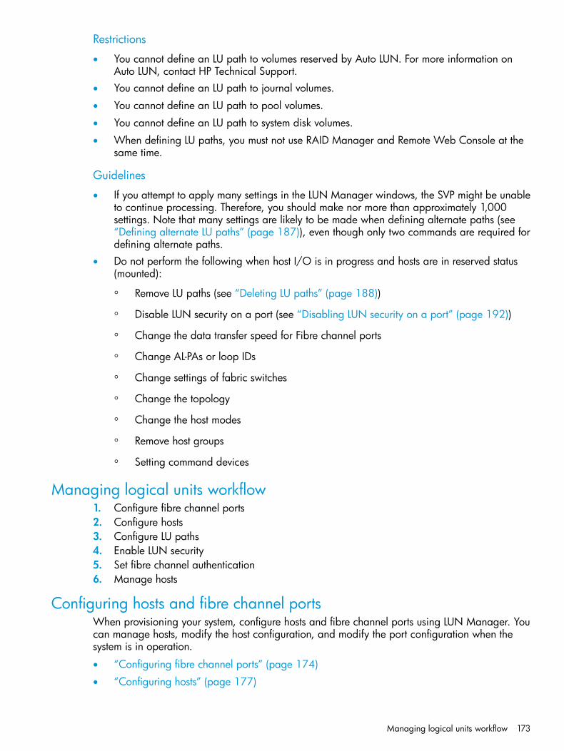
Restrictions
• You cannot define an LU path to volumes reserved by Auto LUN. For more information onAuto LUN, contact HP Technical Support.
• You cannot define an LU path to journal volumes.
• You cannot define an LU path to pool volumes.
• You cannot define an LU path to system disk volumes.
• When defining LU paths, you must not use RAID Manager and Remote Web Console at thesame time.
Guidelines
• If you attempt to apply many settings in the LUN Manager windows, the SVP might be unableto continue processing. Therefore, you should make nor more than approximately 1,000settings. Note that many settings are likely to be made when defining alternate paths (see“Defining alternate LU paths” (page 187)), even though only two commands are required fordefining alternate paths.
• Do not perform the following when host I/O is in progress and hosts are in reserved status(mounted):
◦ Remove LU paths (see “Deleting LU paths” (page 188))
◦ Disable LUN security on a port (see “Disabling LUN security on a port” (page 192))
◦ Change the data transfer speed for Fibre channel ports
◦ Change AL-PAs or loop IDs
◦ Change settings of fabric switches
◦ Change the topology
◦ Change the host modes
◦ Remove host groups
◦ Setting command devices
Managing logical units workflow1. Configure fibre channel ports2. Configure hosts3. Configure LU paths4. Enable LUN security5. Set fibre channel authentication6. Manage hosts
Configuring hosts and fibre channel portsWhen provisioning your system, configure hosts and fibre channel ports using LUN Manager. Youcan manage hosts, modify the host configuration, and modify the port configuration when thesystem is in operation.
• “Configuring fibre channel ports” (page 174)
• “Configuring hosts” (page 177)
Managing logical units workflow 173
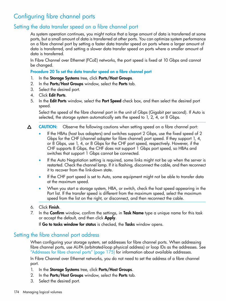
Configuring fibre channel ports
Setting the data transfer speed on a fibre channel portAs system operation continues, you might notice that a large amount of data is transferred at someports, but a small amount of data is transferred at other ports. You can optimize system performanceon a fibre channel port by setting a faster data transfer speed on ports where a larger amount ofdata is transferred, and setting a slower data transfer speed on ports where a smaller amount ofdata is transferred.In Fibre Channel over Ethernet (FCoE) networks, the port speed is fixed at 10 Gbps and cannotbe changed.Procedure 20 To set the data transfer speed on a fibre channel port1. In the Storage Systems tree, click Ports/Host Groups.2. In the Ports/Host Groups window, select the Ports tab.3. Select the desired port.4. Click Edit Ports.5. In the Edit Ports window, select the Port Speed check box, and then select the desired port
speed.Select the speed of the fibre channel port in the unit of Gbps (Gigabit per second). If Auto isselected, the storage system automatically sets the speed to 1, 2, 4, or 8 Gbps.
CAUTION: Observe the following cautions when setting speed on a fibre channel port:• If the HBAs (host bus adapters) and switches support 2 Gbps, use the fixed speed of 2
Gbps for the CHF (channel adapter for fibre channel) port speed. If they support 1, 4,or 8 Gbps, use 1, 4, or 8 Gbps for the CHF port speed, respectively. However, if theCHF supports 8 Gbps, the CHF does not support 1 Gbps port speed, so HBAs andswitches that support 1 Gbps cannot be connected.
• If the Auto Negotiation setting is required, some links might not be up when the server isrestarted. Check the channel lamp. If it is flashing, disconnect the cable, and then reconnectit to recover from the link-down state.
• If the CHF port speed is set to Auto, some equipment might not be able to transfer dataat the maximum speed.
• When you start a storage system, HBA, or switch, check the host speed appearing in thePort list. If the transfer speed is different from the maximum speed, select the maximumspeed from the list on the right, or disconnect, and then reconnect the cable.
6. Click Finish.7. In the Confirm window, confirm the settings, in Task Name type a unique name for this task
or accept the default, and then click Apply.If Go to tasks window for status is checked, the Tasks window opens.
Setting the fibre channel port addressWhen configuring your storage system, set addresses for fibre channel ports. When addressingfibre channel ports, use AL-PA (arbitrated-loop physical address) or loop IDs as the addresses. See“Addresses for fibre channel ports” (page 175) for information about available addresses.In Fibre Channel over Ethernet networks, you do not need to set the address of a fibre channelport.1. In the Storage Systems tree, click Ports/Host Groups.2. In the Ports/Host Groups window, select the Ports tab.3. Select the desired port.
174 Managing logical volumes

4. Select Edit Ports.5. In the Edit Ports window, select the Address (Loop ID) check box, and then select the address.6. Click Finish.7. In the Confirm window, confirm the settings, in Task Name type a unique name for this task
or accept the default, and then click Apply.If Go to tasks window for status is checked, the Tasks window opens.
Addresses for fibre channel portsThe following addresses are available for setting fibre channel ports.
Loop ID(120~125)
AL-PALoop ID(90~119)
AL-PALoop ID(60~89)
AL-PALoop ID(30~59
AL-PALoop ID(0~29)
AL-PA
120109049607630B40EF
1210F9147617531B31E8
122089246627432B22E4
123049345637333B13E2
124029443647234AE4E1
12501953C657135AD5E0
--963A666E36AC6DC
--9739676D37AB7DA
--9836686C38AA8D9
--9935696B39A99D6
--10034706A40A710D5
--10133716941A611D4
--10232726742A512D3
--10331736643A313D2
--1042E7465449F14D1
--1052D7563459E15CE
--1062C765C469D16CD
--1072B775A479B17CC
--1082A7859489818CB
--109297956499719CA
--110278055509020C9
--111268154518F21C7
--112258253528822C6
--113238352538423C5
--1141F8451548224C3
--1151E854E558125BC
--1161D864D568026BA
--1171B874C577C27B9
Configuring fibre channel ports 175

Loop ID(120~125)
AL-PALoop ID(90~119)
AL-PALoop ID(60~89)
AL-PALoop ID(30~59
AL-PALoop ID(0~29)
AL-PA
--11818884B587A28B6
--11917894A597929B5
Setting the fabric switchWhen you configure your storage system, specify whether the hosts and the storage system areconnected via a fabric switch.In Fibre Channel over Ethernet networks, FC Switch is fixed to Enable. Therefore, you do not needto set FC Switch.1. In the Storage Systems tree, click Ports/Host Groups.2. In the Ports/Host Groups window, select the Ports tab.3. Select the desired port.4. Click Edit Ports.5. Select a check box of Fabric, and select ON if you set the fabric switch. If you do not set the
fabric switch, select OFF.6. Click Finish.7. In the Confirm window, confirm the settings, in Task Name type a unique name for this task
or accept the default, and then click Apply.If Go to tasks window for status is checked, the Tasks window opens.
Fibre channel topologyThe term fibre channel topology indicates how devices are connected to each other. Fibre channelprovides the following types of topology:
• Fabric: Uses a fabric switch to connect a large number of devices (up to 16 million) together.Each device will have the full bandwidth of 100 MBps.
• FC-AL (Fibre Channel-Arbitrated Loop): A shared interface that can connect up to 126 devices(AL-ports) together. The full-duplex data transfer rate of 100-MBps bandwidth is shared amongthe devices connected to each other.
• Point-to-point: The simplest fibre topology connects two devices directly together.When configuring your storage system, use the LUN Manager window to specify whether the hostsand the storage system are connected using a fabric switch (see “Example of FC-AL and point-to-pointtopology” (page 177)).If a fabric switch is used, specify FC-AL or point-to-point in the LUN Manager window. FC-AL isthe default. If a fabric switch is used, consult the documentation for the fabric switch to learn whetherFC-AL or point-to-point should be used. Some fabric switches require you to specify point-to-pointto get the system running.If no fabric switch is used, specify FC-AL.In Fibre Channel over Ethernet networks, Connection Type is fixed to P-to-P. Therefore, you do notneed to set Connection Type.
176 Managing logical volumes

Example of FC-AL and point-to-point topology
Configuring hostsYou can configure hosts in your storage system. You can also modify the host configuration withLUN Manager when the system is in operation.Read the following topics concerning host modes before configuring hosts:
• “Host modes for host groups” (page 177)
• “Host mode options” (page 179)Configuring hosts includes the following tasks:
• “Find WWN of the host bus adapter” (page 181))
• “Creating a host group and registering hosts in the host group (in a Fibre Channel environment)”(page 183))
Configure hosts workflow1. Determine the host modes and host mode options you will use2. Determine the WWN of the host bus adapters that you will use.3. Create host groups4. Register host groups
Host modes for host groupsThe following table lists the host modes that are available for use on the P9500 storage system.Carefully review and determine which host modes you will need to use when configuring yoursystem and observe the cautions concerning using certain host modes. Host modes and host modeoptions must be set on the port before the host is connected. If you change host modes or hostmode options after the host is connected, the host (server) will not recognize it.
When to select this modeHost mode
When registering Red Hat Linux server hosts or IRIX server hosts in the host group00 Standard
When registering VMware server hosts in the host group (See Note)01 VMware
When registering OpenVMS server hosts in the host group05 OpenVMS
When registering Tru64 server hosts in the host group07 Tru64
When registering HP-UX server hosts in the host group08 HP
When registering Solaris server hosts in the host group09 Solaris
When registering NetWare server hosts in the host group0A NetWare
When registering Windows server hosts in the host group (See Note)0C Windows
Configuring hosts 177
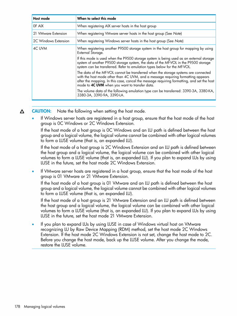
When to select this modeHost mode
When registering AIX server hosts in the host group0F AIX
When registering VMware server hosts in the host group (See Note)21 VMware Extension
When registering Windows server hosts in the host group (See Note)2C Windows Extension
When registering another P9500 storage system in the host group for mapping by usingExternal Storage.
4C UVM
If this mode is used when the P9500 storage system is being used as an external storagesystem of another P9500 storage system, the data of the MF-VOL in the P9500 storagesystem can be transferred. Refer to emulation types below for the MF-VOL.The data of the MF-VOL cannot be transferred when the storage systems are connectedwith the host mode other than 4C UVM, and a message requiring formatting appearsafter the mapping. In this case, cancel the message requiring formatting, and set the hostmode to 4C UVM when you want to transfer data.The volume data of the following emulation type can be transferred: 3390-3A, 3380-KA,3380-3A, 3390-9A, 3390-LA.
CAUTION: Note the following when setting the host mode.• If Windows server hosts are registered in a host group, ensure that the host mode of the host
group is 0C Windows or 2C Windows Extension.If the host mode of a host group is 0C Windows and an LU path is defined between the hostgroup and a logical volume, the logical volume cannot be combined with other logical volumesto form a LUSE volume (that is, an expanded LU).If the host mode of a host group is 2C Windows Extension and an LU path is defined betweenthe host group and a logical volume, the logical volume can be combined with other logicalvolumes to form a LUSE volume (that is, an expanded LU). If you plan to expand LUs by usingLUSE in the future, set the host mode 2C Windows Extension.
• If VMware server hosts are registered in a host group, ensure that the host mode of the hostgroup is 01 VMware or 21 VMware Extension.If the host mode of a host group is 01 VMware and an LU path is defined between the hostgroup and a logical volume, the logical volume cannot be combined with other logical volumesto form a LUSE volume (that is, an expanded LU).If the host mode of a host group is 21 VMware Extension and an LU path is defined betweenthe host group and a logical volume, the logical volume can be combined with other logicalvolumes to form a LUSE volume (that is, an expanded LU). If you plan to expand LUs by usingLUSE in the future, set the host mode 21 VMware Extension.
• If you plan to expand LUs by using LUSE in case of Windows virtual host on VMwarerecognizing LU by Raw Device Mapping (RDM) method, set the host mode 2C WindowsExtension. If the host mode 2C Windows Extension is not set, change the host mode to 2C.Before you change the host mode, back up the LUSE volume. After you change the mode,restore the LUSE volume.
178 Managing logical volumes

Host mode optionsThe following table lists host mode options that are available to use for configuring hosts on aP9500 storage system.
When to select this optionHost mode optionsNo.
When VERITAS Database Edition/Advanced Cluster for Real ApplicationClusters or VERITAS Cluster Server 4.0 or later (I/O fencing function) is used.
VERITAS Database Edition/Advanced Cluster
2
When all of the following conditions are satisfied:TPRLO6• The host mode 0C Windows or 2C Windows Extension is used.
• The Emulex host bus adapter is used.
• The mini-port driver is used.
• TPRLO=2 is specified for the mini-port driver parameter of the host busadapter.
When all of the following conditions are satisfied:Automatic recognition functionof LUN
7• The host mode 00 Standard or 09 Solaris is used.
• SUN StorEdge SAN Foundation Software Version 4.2 or higher is used.
• You want to automate recognition of increase and decrease of deviceswhen genuine SUN HBA is connected.
When all of the following conditions are satisfied:No display for ghost LUN12• The host mode 08 HP is used.
• You want to suppress creation of device files for devices to which pathsare not defined.
When you want to be informed by SIM (service information message) that thenumber of link failures detected between ports exceeds the threshold.
SIM report at link failure113
When all of the following conditions are satisfied:HP TruCluster with ContinuousAccess Synchronous function
14• The host mode 07 Tru64 is used.
• You want to use TruCluster to set a cluster to each of P-VOL and S-VOL forContinuous Access Synchronous or Continuous Access Journal.
When all of the following conditions are satisfied:HACMP15• The host mode 0F AIX is used.
• HACMP 5.1 Version 5.1.0.4 or later, HACMP4.5 Version 4.5.0.13 orlater, or HACMP5.2 or later is used.
When Veritas Cluster Server is used.Veritas Cluster Server22
When you want to shorten the recovery time on the host side if the data transferfailed
REC Command Support 123
When all of the following conditions are satisfied:Set/Report Device Identifierenable
33• Host mode 05 OpenVMS2 or 08 HP is used.
• You want to enable commands to assign a nickname of the device.
• You want to set UUID to identify a logical volume from the host.
When you want to control the following ranges per host group when receivingTarget Reset:
Change the nexus specified inthe SCSI Target Reset
39
• Range of job resetting.
• Range of UAs (Unit Attentions) defined.
Configuring hosts 179
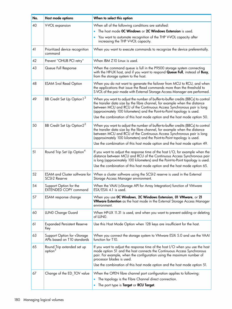
When to select this optionHost mode optionsNo.
When all of the following conditions are satisfied:V-VOL expansion40• The host mode 0C Windows or 2C Windows Extension is used.
• You want to automate recognition of the THP V-VOL capacity afterincreasing the THP V-VOL capacity.
When you want to execute commands to recognize the device preferentially.Prioritized device recognitioncommand
41
When IBM Z10 Linux is used.Prevent "OHUB PCI retry"42
When the command queue is full in the P9500 storage system connectingwith the HP-UX host, and if you want to respond Queue Full, instead of Busy,from the storage system to the host.
Queue Full Response43
When you do not want to generate the failover from MCU to RCU, and whenthe applications that issue the Read commands more than the threshold toS-VOL of the pair made with External Storage Access Manager are performed.
ESAM Svol Read Option48
When you want to adjust the number of buffer-to-buffer credits (BBCs) to controlthe transfer data size by the fibre channel, for example when the distance
BB Credit Set Up Option1349
between MCU and RCU of the Continuous Access Synchronous pair is long(approximately 100 kilometers) and the Point-to-Point topology is used.Use the combination of this host mode option and the host mode option 50.
When you want to adjust the number of buffer-to-buffer credits (BBCs) to controlthe transfer data size by the fibre channel, for example when the distance
BB Credit Set Up Option2350
between MCU and RCU of the Continuous Access Synchronous pair is long(approximately 100 kilometers) and the Point-to-Point topology is used.Use the combination of this host mode option and the host mode option 49.
If you want to adjust the response time of the host I/O, for example when thedistance between MCU and RCU of the Continuous Access Synchronous pairis long (approximately 100 kilometers) and the Point-to-Point topology is used.
Round Trip Set Up Option451
Use the combination of this host mode option and the host mode option 65.
When a cluster software using the SCSI-2 reserve is used in the ExternalStorage Access Manager environment.
ESAM and Cluster software forSCSI-2 Reserve
52
When the VAAI (vStorage API for Array Integration) function of VMwareESX/ESXi 4.1 is used.
Support Option for theEXTENDED COPY command
54
When you use 0C Windows, 2C Windows Extension, 01 VMware, or 21VMware Extention as the host mode in the External Storage Access Managerenvironment.
ESAM response change57
When HP-UX 11.31 is used, and when you want to prevent adding or deletingof LUN0.
LUN0 Change Guard60
Use this Host Mode Option when 128 keys are insufficient for the host.Expanded Persistent ReserveKey
61
When you connect the storage system to VMware ESXi 5.0 and use the VAAIfunction for T10.
Support Option for vStorageAPIs based on T10 standards
63
If you want to adjust the response time of the host I/O when you use the hostmode option 51 and the host connects the Continuous Access Synchronous
Round Trip extended set upoption3
65
pair. For example, when the configuration using the maximum number ofprocessor blades is used.Use the combination of this host mode option and the host mode option 51.
When the OPEN fibre channel port configuration applies to following:Change of the ED_TOV value67• The topology is the Fibre Channel direct connection.
• The port type is Target or RCU Target.
180 Managing logical volumes

When to select this optionHost mode optionsNo.
When using the Page Reclamation function from the environment which isbeing connected to the Linux host.
Support Page Reclamation forLinux
68
When you want the host to be notified of expansion of LUSE volume capacity.Online LUSE expansion69
When you want to change the unit attention (UA) from NOT READY to MEDIUMERROR during the pool-VOLs blockade.
Change the Unit Attention forBlocked Pool-VOLs
71
When using General Parallel File System (GPFS) in the P9500 storage systemconnecting to the AIX host.
AIX GPFS Support72
When using the following functions provided by Windows Server 2012(WS2012) from an environment which is being connected to the WS2012:
Support Option for WS201273
- Thin Provisioning function- Offload Data Transfer (ODX) function
Notes:1. Configure these host mode options only when requested to do so.2. Set the UUID when you set host mode option 33 and host mode 05 openvms is used.3. Host mode options 49, 50, 51, and 65 are enabled only for the 8UFC/16UFC package.4. Set host mode option 51 for both ports on MCU and RCU.
Find WWN of the host bus adapterBefore physically attaching the storage system to hosts, some preparation work needs to beperformed. When configuring a fibre channel environment, first verify that the fibre adapters andthe fibre channel device drivers are installed on the open-system hosts. Next, find the World WideName (WWN) of the host bus adapter that is used in each open-system host.The WWN is a unique identifier for a host bus adapter in an open-system host, consisting of 16hexadecimal digits. The following topics describe how to find the WWN of a host on differentoperating systems. It is best to make a record of the WWNs of the hosts in your storage system,because you will need to enter these WWNs in LUN Manager dialog boxes to specify the hostsused in your storage system.
• “Finding a WWN on Windows” (page 181)
• “Finding a WWN on Oracle® Solaris” (page 182)
• “Finding a WWN on AIX, IRIX, or Sequent” (page 182)
• “Finding WWN for HP-UX” (page 182)
Finding a WWN on WindowsHP supports the Emulex fibre channel adapter in a Windows environment, and will support otheradapters in the future. For further information on fibre channel adapter support, or when using afibre channel adapter other than Emulex, contact HP Technical Support for instructions on findingthe WWN.Before attempting to acquire the WWN of the Emulex adapter, confirm whether the driver installedin the Windows 2000 or Windows Server 2003 environment is an Emulex port driver or an Emulexmini-port driver, and then follow the driver instructions.Procedure 21 To find a WWN on Windows environment with an Emulex mini-port driver1. Verify that the fibre channel adapters and the fibre channel device drivers are installed.2. Log on to the Windows 2000 host with administrator access.3. Go to the LightPulse Utility to open the LightPulse Utility window. If you do not have a shortcut
to the utility:
Configuring hosts 181
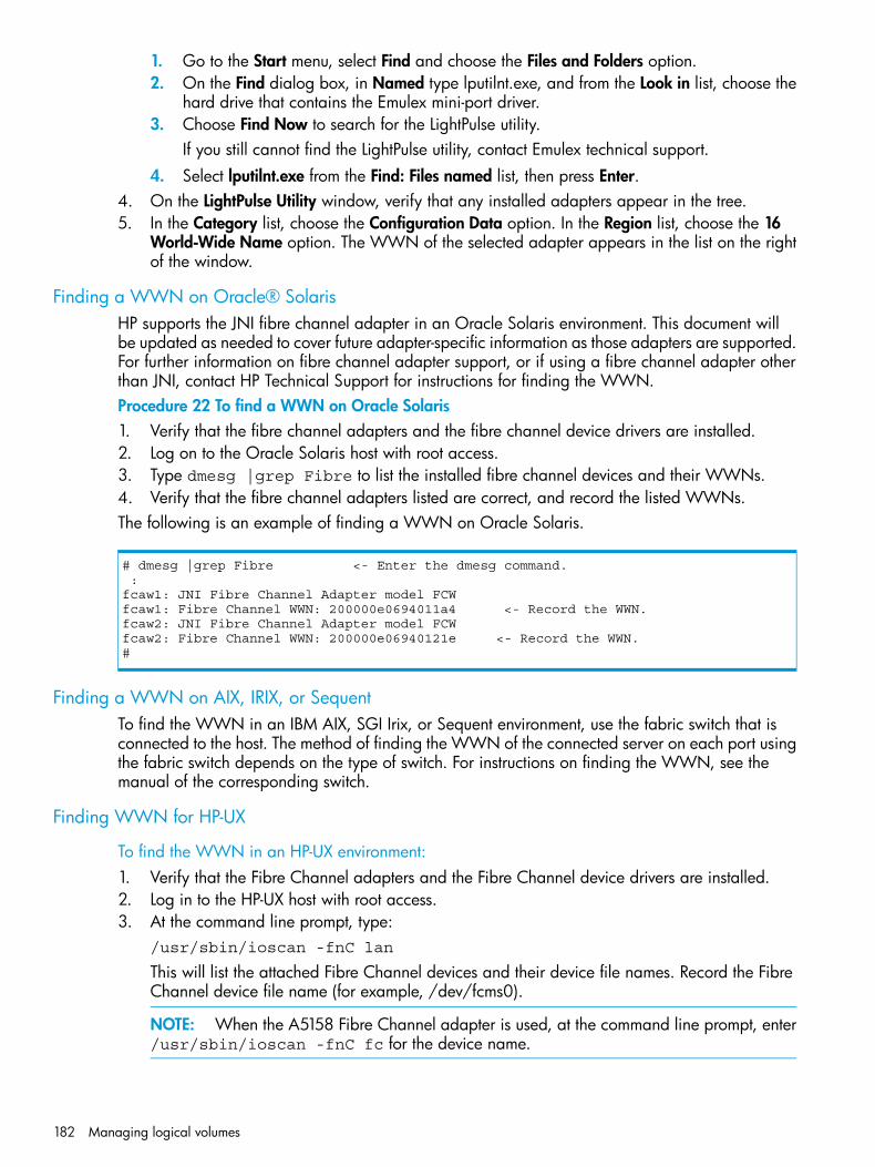
1. Go to the Start menu, select Find and choose the Files and Folders option.2. On the Find dialog box, in Named type lputilnt.exe, and from the Look in list, choose the
hard drive that contains the Emulex mini-port driver.3. Choose Find Now to search for the LightPulse utility.
If you still cannot find the LightPulse utility, contact Emulex technical support.4. Select lputilnt.exe from the Find: Files named list, then press Enter.
4. On the LightPulse Utility window, verify that any installed adapters appear in the tree.5. In the Category list, choose the Configuration Data option. In the Region list, choose the 16
World-Wide Name option. The WWN of the selected adapter appears in the list on the rightof the window.
Finding a WWN on Oracle® SolarisHP supports the JNI fibre channel adapter in an Oracle Solaris environment. This document willbe updated as needed to cover future adapter-specific information as those adapters are supported.For further information on fibre channel adapter support, or if using a fibre channel adapter otherthan JNI, contact HP Technical Support for instructions for finding the WWN.Procedure 22 To find a WWN on Oracle Solaris1. Verify that the fibre channel adapters and the fibre channel device drivers are installed.2. Log on to the Oracle Solaris host with root access.3. Type dmesg |grep Fibre to list the installed fibre channel devices and their WWNs.4. Verify that the fibre channel adapters listed are correct, and record the listed WWNs.The following is an example of finding a WWN on Oracle Solaris.
# dmesg |grep Fibre <- Enter the dmesg command. : fcaw1: JNI Fibre Channel Adapter model FCW fcaw1: Fibre Channel WWN: 200000e0694011a4 <- Record the WWN. fcaw2: JNI Fibre Channel Adapter model FCW fcaw2: Fibre Channel WWN: 200000e06940121e <- Record the WWN.#
Finding a WWN on AIX, IRIX, or SequentTo find the WWN in an IBM AIX, SGI Irix, or Sequent environment, use the fabric switch that isconnected to the host. The method of finding the WWN of the connected server on each port usingthe fabric switch depends on the type of switch. For instructions on finding the WWN, see themanual of the corresponding switch.
Finding WWN for HP-UX
To find the WWN in an HP-UX environment:1. Verify that the Fibre Channel adapters and the Fibre Channel device drivers are installed.2. Log in to the HP-UX host with root access.3. At the command line prompt, type:
/usr/sbin/ioscan -fnC lan
This will list the attached Fibre Channel devices and their device file names. Record the FibreChannel device file name (for example, /dev/fcms0).
NOTE: When the A5158 Fibre Channel adapter is used, at the command line prompt, enter/usr/sbin/ioscan -fnC fc for the device name.
182 Managing logical volumes

4. Use the fcmsutil command along with the Fibre Channel device name to list the WWNfor that Fibre Channel device. For example, to list the WWN for the device with the devicefile name /dev/fcms0, type:/opt/fcms/bin/fcmsutil /dev/fcms0
Record the Fibre Channel device file name (for example, /dev/td0).
NOTE: When using the A5158 Fibre Channel adapter, list the WWN for the device withthe device file name as follows:/opt/fcms/bin/fcmsutil <device file name>
5. Record the WWN and repeat the above steps for each Fibre Channel device that you wantto use.
# /usr/sbin/ioscan -fnC lan <- 1Class I H/W Path Driver S/W State H/W TypeDescription==============================================================lan 0 8/0.5 fcT1_cntl CLAIMED INTERFACE HPFibre Channel Mass Storage Cntl /dev/fcms0 <-2 lan 4 8/4.5 fcT1_cntl CLAIMED INTERFACE HPFibre Channel Mass Storage Cntl /dev/fcms4 <-2lan 5 8/8.5 fcT1_cntl CLAIMED INTERFACE HPFibre Channel Mass Storage Cntl /dev/fcms5 <-2lan 6 8/12.5 fcT1_cntl CLAIMED INTERFACE HPFibre Channel Mass Storage Cntl /dev/fcms6 <-2lan 1 10/8/1/0 btlan4 CLAIMED INTERFACEPCI(10110009) -- Built-in #1lan 2 10/8/2/0 btlan4 CLAIMED INTERFACEPCI(10110009) -- Built-in #2lan 3 10/12/6 lan2 CLAIMED INTERFACEBuilt-in LAN /dev/diag/lan3 /dev/ether3 /dev/lan3## fcmsutil /dev/fcms0 <-3 Local N_Port_ID is = 0x000001 N_Port Node World Wide Name = 0x10000060B0C08294 N_Port Port World Wide Name = 0x10000060B0C08294 <- 4 Topology = IN_LOOP Speed = 1062500000 (bps) HPA of card = 0xFFB40000 EIM of card = 0xFFFA000D Driver state = READY Number of EDB's in use = 0 Number of OIB's in use = 0Number of Active Outbound Exchanges = 1 Number of Active Login Sessions = 2#1: Enter the ioscan.2: Device name3: Enter the fcmsutil command.4: Record the WWN.
Creating a host group and registering hosts in the host group (in a Fibre Channelenvironment)
After discovering the WWNs of the host bus adapters, create a host group and register hosts inthe host groups in a fibre channel environment.
Configuring hosts 183
You can connect multiple server hosts of different platforms to one port of your P9500 storagesystem. When configuring your storage system, you should group server hosts connected to thestorage system by host groups. For example, if HP-UX hosts and Windows hosts are connected toa port, create one host group for HP-UX hosts and create another host group for Windows hosts.Then register HP-UX hosts to the corresponding host group and register Windows hosts to the otherhost group.
NOTE: The above example relates to configurations in which all HP-UX hosts are on the samecluster.
Before you can set LU paths, you must register the hosts in host groups. For example, if HP-UX hostsand Windows hosts are connected to a port, register HP-UX hosts and Windows hosts separatelyin two different host groups.When registering a host, you must also specify the WWN of the host bus adapters.When registering hosts in multiple host groups, set the security switch (LUN security) to enabled,and then specify the WWN of the host bus adapter.When registering a host, you can assign a nickname to the host bus adapter. If you assign anickname, you can easily identify each host bus adapter in the LUN Manager window. AlthoughWWNs are also used to identify each host bus adapter, the nickname that you assign will be morehelpful because you can name host bus adapters after the host installation site or for the hostowners.1. Display the Create Host Groups window by performing one of the following:
• In Remote Web Console, select Create Host Groups from the General Tasks menu anddisplay the Create Host Groups window.
• From the Actions menu, choose Ports/Host Groups, and then Create Host Groups.
• From the Storage Systems tree, click the Ports/Hosts Groups. In the Host Groups page ofthe displayed window, click Create Host Groups.
• From the Storage Systems tree, expand the Ports/Hosts Groups node, and then click therelevant port. In the Host Groups page of the displayed window, click Create Host Groups.
2. Enter the host group name in the Host Group Name box.• It is convenient if you name each host group after the host platform.
• A host group name can consist of up to 32 ASCII characters (letters, numerals, andsymbols). However, you cannot use the following symbols for host group names: \ / : ,; * ? " < > |
• You cannot use space characters for the first and the last characters in host group names.
• Host group names are case-sensitive. For example, the host group names wnt and Wntrepresent different host groups.
3. Select the resource group in which a host group is created.If you select Any, ports to which you may add host groups within all ports assigned to a userare displayed in the Available Ports list. If you select other than Any, ports to which you mayadd host groups within the ports assigned to the selected resource group are displayed in theAvailable Ports list.
4. Select a host mode from the Host Mode list. When selecting a host mode, you must considerthe platform and some other factors.
5. Select hosts to be registered in a host group.If the desired host has ever been connected via a cable to another port in the storage system,select the desired host bus adapter from the Available Hosts list.If the desired host has never been connected via a cable to any port in the storage system,perform the following steps:
184 Managing logical volumes

1. Click Add New Host under the Available Hosts list.The Add New Host dialog box opens.
2. Enter the desired WWN in the HBA WWN box.3. If necessary, enter a nickname for the host bus adapter in the Host Name box.4. Click OK to close the Add New Host dialog box.5. Select the desired host bus adapter from the Available Hosts list.
6. Select the port to which you want to add the host group. For details about host modes, see“Host modes for host groups” (page 177).If you select multiple ports, you may add the same host group to multiple ports by one operation.
7. If necessary, click Options and select host mode options. For details about host mode options,see “Host mode options” (page 179).
NOTE: When you click Options, the dialog box expands to display the list of host modeoptions. The Mode No. column indicates option numbers. Select an option you want to specifyand click Enable.
8. Click Add to add the host group.By repeating steps from 2 to 8, you can create multiple host groups.If you select a row and click Detail, the Host Group Properties window appears. If you selecta row and click Remove, a message appears asking whether you want to remove the selectedrow or rows. If you want to remove the row, click OK.
9. Click Finish to display the Confirm window.To continue to add LUN paths, click Next.
10. Confirm the settings and enter the task name in the Task Name box.A task name can consist of up to 32 ASCII characters (letters, numerals, and symbols). Tasknames are case-sensitive. (date) - (task name) is input by default.If you select a row and click Detail, the Host Group Properties window appears.
11. Click Apply in the Confirm window.If the Go to tasks window for status check box is selected, the Tasks window appears.
Configuring LU pathsWhen provisioning your storage system, and after configuring ports, hosts, and host groups, youmust configure fibre channel LU paths. LUN Manager is required for these tasks. You can alsomodify the LU paths configuration when the system is in operation.
Defining LU pathsIn a fibre channel environment, you must define LU paths and associate host groups with logicalvolumes. For example, if you associate a host group consisting of three hosts with logical volumes,LU paths are defined between the three hosts and the logical volumes.Procedure 23 To define LU paths1. From the Storage Systems tree, click Ports/Hosts Groups. From the Actions menu, select Logical
Device, and then Add LUN Paths.2. Select the desired LDEVs from the Available LDEVs table, and then click Add.
Selected LDEVs are listed in the Selected LDEVs table.3. Click Next.4. Select the desired host groups from the Available Host Groups table, and then click Add.
Selected host groups are listed in the Selected Host Groups table.
Configuring LU paths 185

5. Click Next.6. Confirm the defined LU paths.
• To change the LU path settings, click Change LUN IDs and type the LUN ID that you wantto change.
• To change the LDEV name, click Change LDEV Settings. In the Change LDEV Settingswindow, change the LDEV name.
7. Click Finish.8. In the Confirm window, confirm the settings, in Task Name type a unique name for this task
or accept the default, and then click Apply.If Go to tasks window for status is checked, the Tasks window opens.
Setting a UUIDYou can set an arbitrary ID to identify a logical volume from the host using LUN Manager whenhost mode option 33 is set to on. The ID is referred to as the UUID (user-definable LUN identifier)and is typically composed of a Prefix and an Initial Number.Note the following when setting a UUID:
• If host mode 05 OpenVMS is used, the host mode option 33 is set to ON, LUs that do nothave UUID settings are inaccessible.
• If host mode 05 OpenVMS is used with host mode option 33 set to OFF, LUs that have UUIDsettings are inaccessible.
The following rules apply to setting a UUID:
• These characters cannot be used for UUID: \ / : , ; * ? " < > |
• A space character cannot be used as the first or the last character of a UUID.
• UUID is case-sensitive. For example, Abc and abc are different UUIDs.To keep track of device information, create a correspondence table similar to the example in“Correspondence table for defining devices” (page 187).Procedure 24 To set a UUID1. In the Remote Web Console main window, in the Storage Systems tree, select Ports/Host
Groups.The list of available ports appears in the tree.
2. In the tree, select a port.The host groups that correspond to the port appear in the tree.
3. In the tree, select a host group.Information about the selected host group appears on the right side of the window.
4. Select the LUNs tab.Information about LU paths associated with the selected host group appears.
5. Select one or more logical units to which volumes are assigned (if a volume is assigned to aLU, the columns on the right of the LUN column are not empty).When multiple LUs are selected, the same UUID is set to all selected LUs.
6. Click More Actions, and then select Edit UUIDs.7. In the Edit UUIDs window, in Prefix, type the UUID.
If a UUID is already specified, you can change it. The UUID before changing appears in UUIDin the Edit UUIDs window. However, if multiple LUs, or N/As are selected, the Prefix box isblank.
186 Managing logical volumes

For an OpenVMS server host, you can enter a UUID composed of a Prefix and an InitialNumber. The Prefix may include up to 5 digits, from 1 to 32767, and the Initial Number mayinclude up to 5 digits, from 0 to 32767.For a server host other than OpenVMS, you can enter a UUID composed of a Prefix and anInitial Number. The Prefix may include up to 64 ASCII characters (letters, numerals and symbols)and the Initial Number may include up to 9 digits.When changing the server host OS from HP-UX to Open VMS, or from Open VMS to HP-UX,the same UUID cannot be used continuously. Clear the UUID setting (see “Clearing a UUIDsetting” (page 189)), and then set the proper UUID for a server host.
8. To sequentially number the UUIDs, type the first digit in the Initial Number box. The followingrules apply to the Initial Number:1: Up to 9 numbers are added (1, 2, 3, ... 9).08: Up to 92 numbers are added (08, 09, 10, ... 99).If the host mode is set to OpenVMS, the numbers are as follows:8, 9, 10, ... 9923: Up to 77 numbers are added (23, 24, 25, ... 99).
9. Click Finish.10. In the Confirm window, confirm the settings, in Task Name type a unique name for this task
or accept the default, and then click Apply.If Go to tasks window for status is checked, the Tasks window opens.
Correspondence table for defining devicesWhen configuring the storage system, you will need definition information about devices set byLUN Manager, for example, LUs, LDKC:CU:LDEV, or UUID. A correspondence table similar to theexample below is useful and recommended when collecting this information.
OpenVMS device filename
UUIDLDKC:CU:LDEVLUPort
$1$dga14814800:00:300000BR
$1$dga14914900:00:310001BR
.....
.....
.....
Defining alternate LU pathsYou may want to define alternate LU paths so that if one LU path fails, you will be able to switchto its alternate path.To create an alternate LU path, copy the original LU path from one port to another. For example,if you want to define an alternate for the LU path from the CL1-A port to logical volume 00:00:01,copy the LU path from the CL1-A port to another port.Use one of these methods to copy LU paths:
• Copy all the LU paths defined in a host group
• Copy one or more (but not all) LU paths defined in a host groupBefore taking the following steps:
• See “LUN Manager rules, restrictions, and guidelines” (page 172) for important information.
• To define alternate paths when LUN security is disabled, you must redefine the LU path.
Configuring LU paths 187

Procedure 25 To copy all the LU paths defined in a host group1. In the Remote Web Console main window, in the Storage Systems tree, select Ports/Host
Groups.The list of available ports appears in the tree.
2. Select the Host Groups tab, or select a port from the tree and then select the Host Groups tab.3. Select a host group.4. Select Create Alternative LUN.5. In the Create Alternative LUN Paths window, select the copy destination port from the Available
Ports table, and then click Add.The selected ports appear in the Selected Ports table.
6. Click Finish.7. In the Confirm window, confirm the settings, in Task Name type a unique name for this task
or accept the default, and then click Apply.If Go to tasks window for status is checked, the Tasks window opens.
Procedure 26 To copy one or more (but not all) LU paths defined in a host group1. In the Remote Web Console main window, in the Storage Systems tree, select Ports/Host
Groups.The list of available ports appears in the tree.
2. In the tree, select a port.The host groups corresponding to the port appear.
3. In the tree, select a host group.Information about the selected host group appears on the right side of the window.
4. Select the LUNs tab.Information about LU paths associated with the selected host group appears.
5. Select one or more logical units to which volumes are assigned (if a volume is assigned to alogical unit, the columns on the right of the LUN column are not empty).
6. Select Copy LUN Paths.7. In the Copy LUN Paths window, select the host group to which you want to paste paths from
the Available Host Groups table, and then click Add.The selected host groups appear in the Selected Host Groups table.
8. Click Finish.9. In the Confirm window, confirm the settings, in Task Name type a unique name for this task
or accept the default, and then click Apply.If Go to tasks window for status is checked, the Tasks window opens.
Managing LU pathsYou can modify the LU paths configuration with LUN Manager when the system is in operation,but not when host I/O is in progress. Managing LU paths includes the following tasks:
• “Deleting LU paths” (page 188)
• “Clearing a UUID setting” (page 189)
• “Viewing LU path settings” (page 189)
Deleting LU paths
CAUTION: Do not delete LU paths when host I/O is in progress.
188 Managing logical volumes

1. In the Remote Web Console main window, in the Storage Systems tree, select LDEVs usingeither of the following methods.• Select Logical Devices, and then select the LDEVs tab.
• Select Pools, select a pool, and then select the Virtual Volumes tab.Or, select logical units using the following method.
• Select Ports/Host Groups, select a port, select a host group, and then select the LUNstab.
CAUTION: When an LDEV is selected and Delete LUN Paths is performed, all LUN paths ofthe selected LDEV are deleted by default.
2. Click More Actions and select Delete LUN Paths.3. In the Delete LUN Paths window, confirm that the LU paths that you want to delete are listed
in Selected LUN Paths.If LU paths that you do not want to delete are listed, select the LU path you do not want todelete, and then click Remove from Delete process.
4. If necessary, check the Delete all defined LUN paths to above LDEVs check box. When checked,all additional LU paths on the selected LDEVs will be deleted.
5. Click Finish to open the Confirm window.If you want to start shredding operations to delete the data of the volume, click Next. Fordetailed information about shredding operations, see the HP XP P9000 Volume Shredder forOpen and Mainframe Systems User Guide.
6. In the Confirm window, confirm the settings, in Task Name type a unique name for this taskor accept the default, and then click Apply.If Go to tasks window for status is checked, the Tasks window opens.
If you delete many paths at one time, the deletion process may take time and the dialog box mayseem to hang temporarily.
Clearing a UUID settingYou can clear the UUID setting that has been set to identify a logical volume from the host.1. In the Remote Web Console main window, in the Storage Systems tree, click Logical Devices,
and then select the LDEVs tab.2. Select the LDEVs for which you want to clear the UUID setting.3. Select Delete UUIDs. The Delete UUIDs window opens.4. In the Confirm window, confirm the settings, in Task Name type a unique name for this task
or accept the default, and then click Apply.If Go to tasks window for status is checked, the Tasks window opens.
Viewing LU path settings1. In the Storage Systems tree, click Ports/Host Groups.
The list of available ports appears in the tree.2. In the tree, select a port.
The host groups corresponding to the port appear.3. In the tree, select a host group.
Information about the selected host group appears on the right side of the window.4. Select the LUNs tab.
Information about LU paths associated with the selected host group appear.
Configuring LU paths 189

5. In the LUN ID column, click the LUN to open the LUN Properties window.
Releasing LUN reservation by hostThe following explains how to release forcibly a LUN reservation by a host.
Prerequisites• You must have the Storage Administrator (system resource management) role to perform this
task.
CAUTION: If you perform the releasing a LUN reservation by a host, the host which isconnected to LDEV by LUN path is affected.
To release a LUN reservation by a host:1. Click Ports/Host Groups in the Storage Systems tree.
The list of available ports appears in the tree.2. In the tree, select a port.
The host groups corresponding to the port appear.3. In the tree, select a host group.
Information about the selected host group appears on the right side of the window.4. Select the LUNs tab on the right side of the window.
Information about LU paths associated with the selected host group appears.5. On the menu bar, click Actions, Ports/Hosts Groups, and then View Host-Reserved LUNs. Or,
select View Host-Reserved LUNs from the lower right of the window. The Host-Reserved LUNswindow opens.
6. In the Host-Reserved LUNs window, select LUN to release the reservation by the host, andthen select Release Host-Reserved LUNs. The Release Host-Reserved LUNs window opens.
7. Confirm the settings and enter the task name in the Task Name box.A task name can consist of up to 32 ASCII characters (letters, numerals, and symbols). Tasknames are case-sensitive. (date) - (task name) is input by default.
8. Click Apply in the Release Host-Reserved LUNs window.If the Go to tasks window for status check box is selected, the Tasks window appears.
LUN security on portsTo protect mission-critical data in your storage system from illegal access, apply security policiesto logical volumes. Use LUN Manager to enable LUN security on ports to safeguard LUs from illegalaccess.If LUN security is enabled on ports, host groups affect which host can access which LUs. Hosts canaccess only the LUs associated with the host group to which the hosts belong. Hosts cannot accessLUs associated with other host groups. For example, hosts in the hp-ux host group cannot accessLUs associated with the windows host group. Also, hosts in the windows host group cannot accessLUs associated with the hp-ux host group.
Examples of enabling and disabling LUN security on ports
Enabling LUN securityIn the following example, LUN security is enabled on port CL1-A. The two hosts in the hg-lnxhost group can access only three LUs (00:00:00, 00:00:01, and 00:00:02). The two hosts in the
190 Managing logical volumes

hg-hpux host group can access only two LUs (00:02:01 and 00:02:02). The two hosts in thehg-solar host group can access only two LUs (00:01:05 and 00:01:06).
Disabling LUN securityTypically, you do not need to disable LUN security on ports. For example, if LUN security is disabledon a port, the connected hosts can access only the LUs associated with host group 0, and cannotaccess LUs associated with any other host group.
Host group 0 is the only host group reserved, by default, for each port. If you use the LUN Managerwindow to view a list of host groups in a port, host group 0, indicated by 00, usually appears atthe top of the list.The default name of host group 0 consists of the port name, a hyphen, and the number 00. Forexample, the default name of host group 0 for port 1A is 1A-G00. However, you can change thedefault name of the host group 0.
LUN security on ports 191

LUN security is disabled, by default, on each port. When you configure your storage system, youmust enable LUN security on each port to which hosts are connected.
Enabling LUN security on a portTo protect mission-critical data in your storage system from illegal access, secure the logical volumesin the storage system. Use LUN Manager to secure LUs from illegal access by enabling LUN securityon ports.By default, LUN security is disabled on each port. When registering hosts in multiple host groups,you must enable LUN security (set the switch to enabled). When you change LUN security fromdisabled to enabled, you must specify the WWN of the host bus adapter.
CAUTION: It is best to enable LUN security on each port when configuring your storage system.Although you can enable LUN security on a port when host I/O is in progress, I/O is rejected witha security guard after enabling.
1. Click Ports/Host Groups in the Storage Systems tree.2. Select the Ports tab.3. Select the desired port.4. Select Edit Ports. The Edit Ports window opens.5. Select the Port Security check box, and then select Enable.6. Click Finish. A message appears, confirming whether to switch the LUN security. Clicking OK
opens the Confirm window.7. In the Confirm window, confirm the settings, in Task Name type a unique name for this task
or accept the default, and then click Apply.If Go to tasks window for status is checked, the Tasks window opens.
Disabling LUN security on a port
CAUTION: Do not disable LUN security on a port when host I/O is in progress.
1. Click Ports/Host Groups in the Storage Systems tree.2. Select the Ports tab.3. Select the desired port.4. Select Edit Ports The Edit Ports window opens.5. Select the Port Security check box, and then select Disable.6. Click Finish. If disabling LUN security, a message appears, indicating that only host group 0
(the group whose number is 00) is to be enabled. Clicking OK opens the Confirm window.7. In the Confirm window, confirm the settings, in Task Name type a unique name for this task
or accept the default, and then click Apply.If Go to tasks window for status is checked, the Tasks window opens.
Setting fibre channel authenticationWhen configuring a fibre channel environment, use the Authentication window to set userauthentication on host groups, fibre channel ports, and fabric switches of the storage system.In Fibre Channel over Ethernet networks, user authentication is not supported.The hosts to be connected must be configured for authentication by host groups (and forauthentication of host groups by the host, if required). For details on how to configure the host forCHAP authentication, see the documentation of the operating system and fibre channel driver inyour environment.
192 Managing logical volumes
The following topics provide information for managing user authentication on host groups, fibrechannel ports, and fabric switches:
• “User authentication” (page 193)
• “Fibre channel authentication” (page 199)
• “Fibre channel port authentication” (page 203)
• “Setting fibre channel port authentication” (page 203))
• “Registering user information on a fibre channel port” (page 203))
• “Registering user information on a fabric switch” (page 204))
• “Clearing fabric switch user information” (page 204))
• “Setting the fabric switch authentication mode” (page 205))
• “Enabling or disabling fabric switch authentication” (page 205))
User authenticationWhen configuring a fibre channel environment, use LUN Manager to set user authentication forports between the P9500 storage system and hosts. In a fibre channel environment, the ports andhosts use Null DH-CHAP or CHAP (Challenge Handshake Authentication Protocol with a NullDiffie-Hellmann algorithm) as the authentication method.User authentication is performed in a fibre channel environment in three phases:1. A host group of the storage system authenticates a host that attempts to connect (authentication
of hosts).2. The host authenticates the connection-target host group of the storage system (authentication
of host groups).
CAUTION: Because the host bus adapters at present do not support this function, thisauthentication phase is unusable in the fibre channel environment.
3. A target port of the storage system authenticates a fabric switch that attempts to connect(authentication of fabric switches).
The storage system performs user authentication by host groups. Therefore, the host groups andhosts need to have their own user information for performing user authentication.When a host attempts to connect to the storage system, the authentication of hosts phase starts. Inthis phase, first it is determined whether the host group requires authentication of the host. If it doesnot, the host connects to the storage system without authentication. If it does, authentication isperformed for the host, and when the host is authenticated successfully, processing goes on to thenext phase.After successful authentication of the host, if the host requires user authentication for the host groupthat is the connection target, the authentication of host groups phase starts. In this way, the hostgroups and hosts authenticate with each other, that is, mutual authentication. In the authenticationof host groups phase, if the host does not require user authentication for the host group, the hostconnects to the storage system without authentication of the host group.The settings for authentication of host groups are needed only when you want to perform mutualauthentication. The following topics explain the settings required for user authentication.
• “Settings for authentication of hosts” (page 193)
• “Settings for authentication of ports (required if performing mutual authentication)” (page 194)
Settings for authentication of hostsOn the storage system, use LUN Manager to specify whether to authenticate hosts on each hostgroup.
Setting fibre channel authentication 193
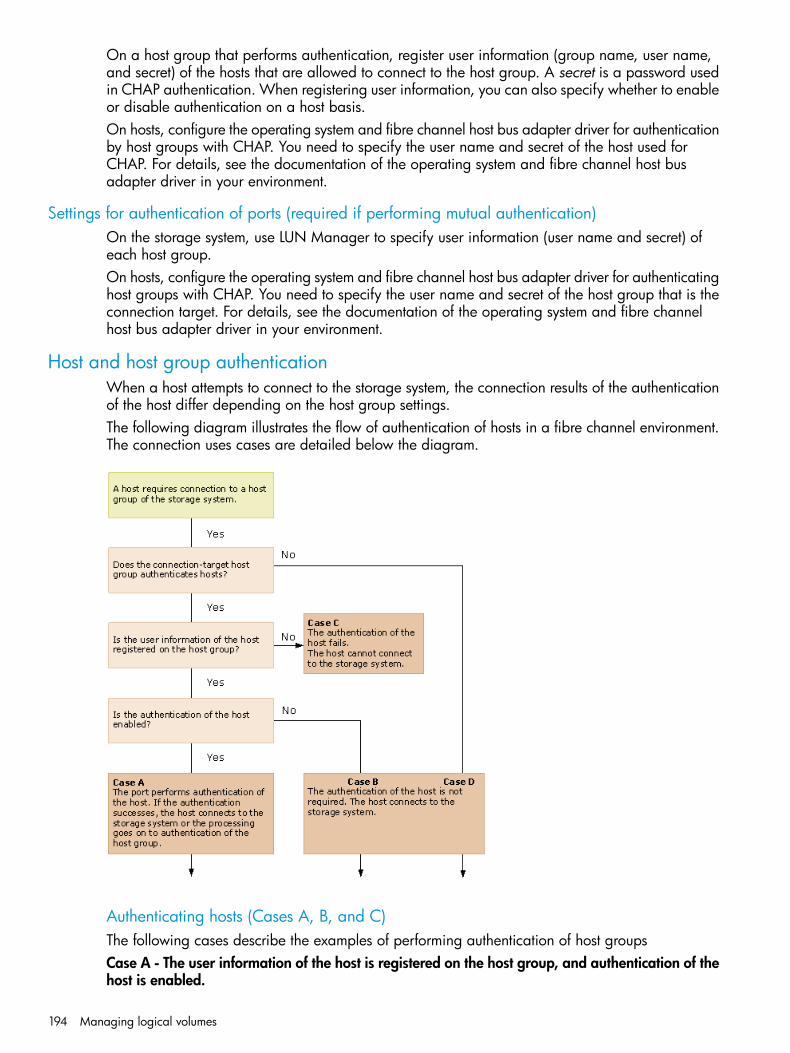
On a host group that performs authentication, register user information (group name, user name,and secret) of the hosts that are allowed to connect to the host group. A secret is a password usedin CHAP authentication. When registering user information, you can also specify whether to enableor disable authentication on a host basis.On hosts, configure the operating system and fibre channel host bus adapter driver for authenticationby host groups with CHAP. You need to specify the user name and secret of the host used forCHAP. For details, see the documentation of the operating system and fibre channel host busadapter driver in your environment.
Settings for authentication of ports (required if performing mutual authentication)On the storage system, use LUN Manager to specify user information (user name and secret) ofeach host group.On hosts, configure the operating system and fibre channel host bus adapter driver for authenticatinghost groups with CHAP. You need to specify the user name and secret of the host group that is theconnection target. For details, see the documentation of the operating system and fibre channelhost bus adapter driver in your environment.
Host and host group authenticationWhen a host attempts to connect to the storage system, the connection results of the authenticationof the host differ depending on the host group settings.The following diagram illustrates the flow of authentication of hosts in a fibre channel environment.The connection uses cases are detailed below the diagram.
Authenticating hosts (Cases A, B, and C)The following cases describe the examples of performing authentication of host groupsCase A - The user information of the host is registered on the host group, and authentication of thehost is enabled.
194 Managing logical volumes

The host group authenticates the user information sent from the host. If authentication of the hostis successful, either of the following occurs:
• When the host is configured for mutual authentication, authentication of the host group isperformed.
• When the host is not configured for mutual authentication, the host connects to the storagesystem.
If the host is not configured for authentication by host groups with CHAP, the authentication failsand the host cannot connect to the storage system.Case B - The user information of the host is registered on the host group, but authentication of thehost is disabled.The host group does not perform authentication of the host. The host will connect to the storagesystem without authentication regardless of whether the host is configured for authentication byhost groups with CHAP.Case C - The user information of the host is not registered on the host group.Regardless of the setting on the host, the host group performs authentication of the host, but resultsin failure. The host cannot connect to the storage system.
Not authenticating hosts (Case D)Case D is an example of connecting via a host group that does not perform authentication of hosts.The host will connect to the storage system without authentication of the host regardless of whetherthe host is configured for authentication by host groups with CHAP. In this case, though you neednot register user information of the host on the host group, you can register it.You should register user information of all the hosts to be connected to a host group that performsauthentication of hosts. To allow a specific host to connect to such a host group withoutauthentication, configure the host group and the host as follows.On the host group: Register the user information of the host you want to allow to connect withoutauthentication, and then disable the authentication setting of the host.
Example of authenticating hosts in a fibre channel environmentFollowing is an example of authentication of hosts in a fibre channel environment. In this figure,WWNs of host bus adapters (HBAs) are abbreviated, such as A, B, and so on.
Setting fibre channel authentication 195
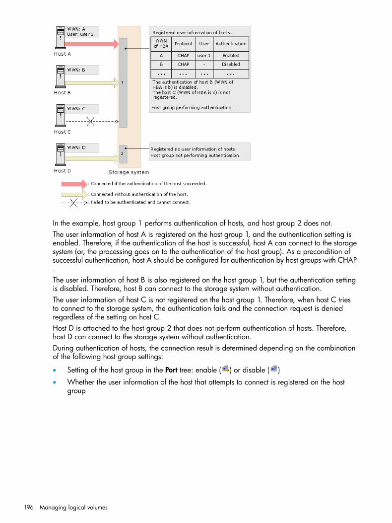
In the example, host group 1 performs authentication of hosts, and host group 2 does not.The user information of host A is registered on the host group 1, and the authentication setting isenabled. Therefore, if the authentication of the host is successful, host A can connect to the storagesystem (or, the processing goes on to the authentication of the host group). As a precondition ofsuccessful authentication, host A should be configured for authentication by host groups with CHAP.The user information of host B is also registered on the host group 1, but the authentication settingis disabled. Therefore, host B can connect to the storage system without authentication.The user information of host C is not registered on the host group 1. Therefore, when host C triesto connect to the storage system, the authentication fails and the connection request is deniedregardless of the setting on host C.Host D is attached to the host group 2 that does not perform authentication of hosts. Therefore,host D can connect to the storage system without authentication.During authentication of hosts, the connection result is determined depending on the combinationof the following host group settings:
• Setting of the host group in the Port tree: enable ( ) or disable ( )
• Whether the user information of the host that attempts to connect is registered on the hostgroup
196 Managing logical volumes
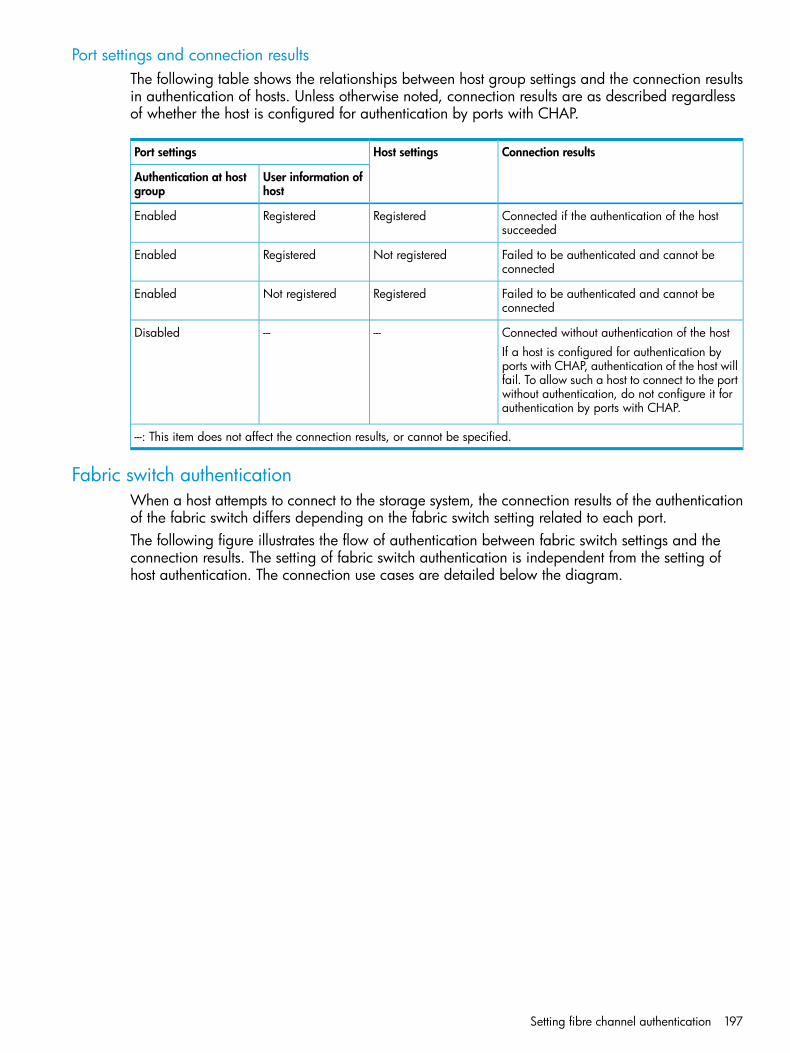
Port settings and connection resultsThe following table shows the relationships between host group settings and the connection resultsin authentication of hosts. Unless otherwise noted, connection results are as described regardlessof whether the host is configured for authentication by ports with CHAP.
Connection resultsHost settingsPort settings
User information ofhost
Authentication at hostgroup
Connected if the authentication of the hostsucceeded
RegisteredRegisteredEnabled
Failed to be authenticated and cannot beconnected
Not registeredRegisteredEnabled
Failed to be authenticated and cannot beconnected
RegisteredNot registeredEnabled
Connected without authentication of the host------DisabledIf a host is configured for authentication byports with CHAP, authentication of the host willfail. To allow such a host to connect to the portwithout authentication, do not configure it forauthentication by ports with CHAP.
---: This item does not affect the connection results, or cannot be specified.
Fabric switch authenticationWhen a host attempts to connect to the storage system, the connection results of the authenticationof the fabric switch differs depending on the fabric switch setting related to each port.The following figure illustrates the flow of authentication between fabric switch settings and theconnection results. The setting of fabric switch authentication is independent from the setting ofhost authentication. The connection use cases are detailed below the diagram.
Setting fibre channel authentication 197

Authenticating fabric switches by ports (Cases A, B, and C)
• If the user information of the fabric switch is registered on the port, and authentication of thefabric switch is enabled (Case A)Each port authenticates the fabric switch. If the authentication of the fabric switch endssuccessfully, either of the following actions occurs:
◦ When the fabric switch is configured for mutual authentication, processing continues toauthentication of the port.
◦ When the fabric switch is not configured for mutual authentication, the fabric switchconnects to the storage system.
If the fabric switch of the port is not configured for authentication with CHAP, the authenticationfails and the fabric switch cannot connect to the storage system.
• If the user information of the fabric switch is registered on the port, but authentication of thefabric switch is disabled (Case B)Each port does not perform authentication of the fabric switch. The fabric switch connects tothe storage system without authentication regardless of whether the fabric switch is configuredfor authentication with CHAP.
• If the user information of the fabric switch is not registered on the port (Case C)Regardless of the setting on the fabric switch, the port performs authentication of the fabricswitch, but results in failure. The fabric switch cannot connect to the storage system.
Not authenticating fabric switches by ports (Case D)The fabric switch connects to the storage system without authentication of the host regardless ofwhether the fabric switch is configured for authentication with CHAP. In this case, though you neednot register the user information of the fabric switch on the port, you can register it.
198 Managing logical volumes

During authentication of hosts, the connection result is determined depending on the combinationof the following port settings:
• Setting of the port in the Port tree: enable ( ) or disable ( )
• Whether the user information of the fabric switch that attempts to connect is registered on theport
Fabric switch settings and connection resultsThe following table shows the relationship between the combinations of port settings and theconnection results in authentication of fabric switches. Unless otherwise noted, connection resultsare as described regardless of whether the host is configured for authentication by fabric switcheswith CHAP.
Connection resultsfabric switchsettings
Port Settings
User information offabric switch
Authentication at fabricswitch
Connected if the authentication of the fabric switchsucceeded
RegisteredRegisteredEnabled
Failed to be authenticated and cannot be connectedNot registeredRegisteredEnabled
Failed to be authenticated and cannot be connectedRegisteredNot registeredEnabled
Connected without authentication of the fabricswitch
------Disabled
If a fabric switch is configured for authenticationby ports with CHAP, authentication of the host willfail. To allow such a fabric switch to connect to theport without authentication, do not configure it forauthentication by ports with CHAP.
---: This item does not affect the connection results, or cannot be specified.
Mutual authentication of portsIf mutual authentication is required, when authentication of a host is successful, the host in returnauthenticates the port. In authentication of ports, when user information (user name and secret)specified on the port side matches with that stored on the host, the host allows the host group toconnect.
Fibre channel authentication
Enabling or disabling host authentication on a host groupYou can specify whether to authenticate hosts on each host group. Change the user authenticationsettings of host groups to enable or disable authentication of hosts. By default, user authenticationis disabled.Procedure 27 To enable host authentication on a host group1. On the menu bar, select Actions, Port/Host Group, and then Authentication.
2. In the Authentication window, click to change to Modify mode.3. In the Port tree, double-click the Storage System folder.
If the storage system contains any fibre channel adapters, the Fibre folder appears below theStorage System folder.
Setting fibre channel authentication 199

4. Double-click the Fibre folder and fibre channel port icon under the Fibre folder.When you double-click the Fibre folder, the fibre channel ports contained in the storage systemappear as icons. If you double-click the fibre channel ports, host groups appear as icons. Onthe right of each icon appears the host group name.
indicates the host group authenticates hosts. This is the default.
indicates the host group does not authenticate hosts.
5. Right-click a host group that appears with and select Authentication:Disable -> Enable. Thehost group icon changes to , and the port name appears in blue.
6. Click Apply in the Authentication window. A message appears asking whether to apply thesettings to the storage system.
7. Click OK to close the message. The settings are applied to the storage system.
To return the host group setting to , perform the same operation, except select theAuthentication:Enable -> Disable menu in step 4.
Registering host user informationOn a host group that performs authentication of hosts, register user information of all hosts thatyou allow to connect.You should register user information of all the hosts to be connected to a host group that performsauthentication of hosts. To allow a specific host to connect to such a host group withoutauthentication, configure the host group and the host as follows.On the host: it does not matter if you configure the host for authentication by ports with CHAP, ornot.1. On the menu bar, select Actions, Port/Host Group, and then Authentication.
2. In the Authentication window, click to change to Modify mode.3. In the Port tree, select a port or host group on which you want to register user information of
a host.The user information of hosts currently registered on the selected port or host group appearsin the Authentication Information (Host) list below the Authentication Information (Target) list.
You can register user information of a host even if the port status is . In this case, however,the registered user information of a host is ignored.
4. Right-click any point in the Authentication Information (Host) list and select Add New UserInformation. The Add New User Information (Host) dialog box opens.
5. In this dialog box, specify the following user information of the host you want to allowconnection.• Group Name: Specify the group name of host bus adapter. Select one from the list. In
the list, all the group names of host bus adapters connected to the selected port by thecable appear.
• User Name: Specify the WWN of the host bus adapter with up to 16 characters. Youcan use alphanumeric characters in a user name.
• Secret: Specify the secret (that is, a password used in CHAP authentication) between 12to 32 characters.You can use alphanumeric characters, spaces, and the following symbols in a secret: . -+ @ _ = : [ ] , ~
• Re-enter Secret: Specify the secret, again, for confirmation.• Protocol: Specify the protocol used in the user authentication. This protocol is fixed to
CHAP.
200 Managing logical volumes

6. Click OK to close the Add New User Information (Host) dialog box. The specified userinformation of the host is added in blue in the Authentication Information (Host) list of theAuthentication window.
7. Click Apply in the Authentication window. A message appears asking whether to apply thesettings to the storage system.
8. Click OK to close the message. The settings are applied to the storage system.
Changing host user information registered on a host groupYou can change the registered user name or secret of a host, and enable and disable authenticationsettings after registration.You cannot change the WWN when you change user information.Procedure 28 To change host user information registered on a host group1. On the menu bar, select Actions, Port/Host Group, and then Authentication.
2. In the Authentication window, click to change to Modify mode.3. In the Port tree, expand the Fibre folder and select a port or host group on which the user
information you want to change is registered.All the user information of the hosts registered on the selected port or host group appears inthe Authentication Information (Host) list below the Authentication Information (Target).
4. In the User Information (Host) list, right-click a user information item that you want to changeand select Change User Information. The Change User Information (Host) dialog box opens.
5. Change the user information of the host in the Change User Information (Host) dialog box.You can change the specifications of User Name, and Secret.
6. Click OK to close the Change User Information (Host) dialog box. The user information of thehost is changed in blue in the Authentication Information (Host) list of the Authenticationwindow.
7. Click Apply in the Authentication window. A message appears asking whether to apply thesettings to the storage system.
8. Click OK to close the message. The settings are applied to the storage system.
Deleting host user informationYou can delete registered user information from a host group.1. On the menu bar, select Actions, Port/Host Group, and then Authentication.
2. In the Authentication window, click to change to Modify mode.3. In the Port tree, expand the Fibre folder and select a port or host group on which the user
information you want to delete is registered.The user information of hosts currently registered on the selected port or host group appearsin the Authentication Information (Host) list below the Authentication Information (Target).
4. In the Authentication Information (Host) list, right-click a user information item that you wantto delete.
5. Select Delete User Information. The Delete Authentication Information dialog box opens askingwhether to delete the selected host user information.
6. Click OK to close the message.7. Click Apply in the Authentication window. A message appears asking whether to apply the
setting to the storage system.8. Click OK to close the message. The setting is applied to the storage system.
Setting fibre channel authentication 201

Registering user information for a host group (for mutual authentication)You can perform mutual authentication by specifying user information for host groups on the storagesystem ports. Specify unique user information for each host group. You can change the specifieduser information for host groups in the same way you initially specify it.Procedure 29 To specify user information for a host group1. On the menu bar, select Actions, Port/Host Group, and then Authentication.
2. In the Authentication window, click to change to Modify mode.3. In the Port tree, select a port or host group whose user information you want to specify.
The currently registered user information of the selected port or host group appears in theAuthentication Information (Target) list.
4. Right-click any point in the Authentication Information (Target) list and select SpecifyAuthentication information.
5. In the Specify Authentication Information dialog box, specify the user information of the portor host group selected in the Port tree.• Port Name: The port name of the selected port appears. You cannot change the port
name.• User Name: Specify the user name of the host group with up to 16 characters. You can
use specified alphanumeric characters. User names are case-sensitive.• Secret: Specify the secret (that is, a password used in CHAP authentication) between 12
to 32 characters. You can use alphanumeric characters, spaces, and the following symbolsin a user name: . - + @ _ = : / [ ] , ~
• Re-enter Secret: Specify the secret, again, for confirmation.6. Click OK to close the Specify Authentication Information dialog box. The specified user
information of the port appears in blue in the Authentication Information (Target) list of theAuthentication window.
7. Click Apply in the Authentication window. A message appears asking whether to apply thesettings to the storage system.
8. Click OK to close the message. The settings are applied to the storage system.
Clearing user information from a host groupYou can clear user information from a host group.1. On the menu bar, select Actions, Port/Host Group, and then Authentication.
2. In the Authentication window, click to change to Modify mode.3. In the Port tree, expand the Fibre folder and select a port or host group whose user information
you want to clear.The currently registered user information of the port or host group appears in the AuthenticationInformation (Target).
4. Right-click any point in the Authentication Information (Target) list and select Clear Authenticationinformation. The Clear Authentication Information dialog box opens asking whether to clearthe user information of the selected host group.
5. Click OK to close the Clear Authentication Information dialog box. The user information ofthe selected host group disappears from the Authentication Information (Target) list.
6. Click Apply in the Authentication window. A message appears asking whether to apply thesetting to the storage system.
7. Click OK to close the message. The setting is applied to the storage system.
202 Managing logical volumes

Fibre channel port authentication
Setting fibre channel port authenticationYou can perform user authentication in a fibre channel environment by specifying authenticationinformation on the fibre channel ports of the storage system.1. On the menu bar, select Actions, Port/Host Group, and then Authentication.
2. In the Authentication window, click to change to Modify mode.3. In the Port tree, double-click the Storage System folder.
If the storage system contains any fibre channel adapters, the Fibre folder appears below theStorage System folder. Information about the port appears in the Port Information list of theAuthentication window.
4. Right-click any point in the Port Information list and select Set Port Information.5. In the Set Port Information dialog box, specify the port information.
• Time out: Specify the period of time from when authentication fails to when the nextauthentication session is ended. This period of time is between 15 to 60 seconds. Theinitial value of the Time out is 45 seconds.
• Refusal Interval: Specify the interval from when connection to a port fails to when thenext authentication session starts, with up to 60 minutes. The initial value of the RefusalInterval is 3 minutes.
• Refusal Frequency: Specify the number of times of authentication allowable for connectionto a port with up to 10 times. The initial value of the Refusal Frequency is 3 times.
6. Click OK to close the Set Port Information dialog box.7. Click Apply in the Authentication window. A message appears asking whether to apply the
settings to the storage system.8. Click OK to close the message. The settings are applied to the storage system.
Registering user information on a fibre channel portYou can perform user authentication in a fibre channel environment by registering user informationon the fibre channel ports of the storage system.1. On the menu bar, select Actions, Port/Host Group, and then Authentication.
2. In the Authentication window, click to change to Modify mode.3. In the Port tree, double-click the Storage System folder.
If the storage system contains any fibre channel adapters, the Fibre folder appears below theStorage System folder.
4. In the Port tree, double-click the Fibre folder. Information about the port appears in the treeof the Authentication window.
5. Right-click any icon of port in the Port tree and select Default Setting(User Name / Secret).6. In the Default Setting(User Name/Secret) dialog box, specify the user information.
• User Name: Specify the user name of fibre channel with up to 16 characters. You canuse alphanumeric characters in a user name. User names are case-sensitive.
• Secret: Specify the secret (that is, a password used in CHAP authentication) between 12to 32 characters.You can use alphanumeric characters, spaces, and the following symbols in a secret: . -+ @ _ = : / [ ] , ~
• Re-enter Secret: Specify the secret, again, for confirmation.7. Click OK to close the Default Setting (User Name/Secret) dialog box.
Setting fibre channel authentication 203
8. Click Apply in the Authentication window. A message appears asking whether to apply thesetting to the storage system.
9. Click OK to close the message. The setting is applied to the storage system.
Registering user information on a fabric switchYou can perform user authentication in a fibre channel environment by registering user informationon the fabric switch of the storage system.1. On the menu bar, select Actions, Port/Host Group, and then Authentication.
2. In the Authentication window, click to change to Modify mode.3. In the Port tree, double-click the Storage System folder.
If the storage system contains any fibre channel adapters, the Fibre folder appears below theStorage System folder.
4. In the Port tree, double-click the Fibre folder. Information about the fabric switch appears inthe Fabric Switch Information list below the Port Information list.
5. Right-click any point in the Fabric Switch Information list and select Specify User Information.6. In the Specify Authentication Information dialog box, specify the user information of the host
you want to allow connection.• User Name: Specify the user name of the fabric switch with up to 16 characters.
You can use alphanumeric characters in a user name.
• Secret: Specify the secret (that is, a password used in CHAP authentication) between 12to 32 characters.You can use alphanumeric characters, spaces, and the following symbols in a secret: . -+ @ _ = : / [ ] , ~
• Re-enter Secret: Specify the secret, again, for confirmation.7. Click OK to close the Specify Authentication Information dialog box.8. Click Apply in the Authentication window. A message appears asking whether to apply the
settings to the storage system.9. Click OK to close the message. The settings are applied to the storage system.
Clearing fabric switch user informationYou can clear the specified user information of a fabric switch from the storage system.1. On the menu bar, select Actions, Port/Host Group, and then Authentication.
2. In the Authentication window, click to change to Modify mode.3. In the Port tree, double-click the Storage System folder.
If the storage system contains any fibre channel adapters, the Fibre folder appears below theStorage System folder.
4. In the Port tree, double-click the Fibre folder. Information about the fabric switch appears inthe Fabric Switch Information list below the Port Information list.
5. Right-click any point in the Fabric Switch Information list and select Clear Authenticationinformation. The Clear Authentication Information dialog box opens asking whether to clearthe user information of the selected fabric switch.
6. Click OK to close the Clear Authentication Information dialog box.7. Click Apply in the Authentication window. A message appears asking whether to apply the
settings to the storage system.8. Click OK to close the message. The settings are applied to the storage system.
204 Managing logical volumes
Setting the fabric switch authentication modeYou can specify the authentication mode of a fabric switch.1. On the menu bar, select Actions, Port/Host Group, and then Authentication.
2. In the Authentication window, click to change to Modify mode.3. In the Port tree, double-click the Storage System folder.
If the storage system contains any fibre channel adapters, the Fibre folder appears below theStorage System folder.
4. In the Port tree, double-click the Fibre folder. Information about the fabric switch appears inthe Fabric Switch Information list below the Port Information list.
5. Right-click any point in the Fabric Switch Information list and select Authentication Mode:unidirectional->bi-directional.
6. Click Apply in the Authentication window. A message appears asking whether to apply thesettings to the storage system.
7. Click OK to close the message. The settings are applied to the storage system.To return the fibre channel setting, perform the same operation, except that you must select theAuthentication Mode: bi-directional->unidirectional menu in step 4.
Enabling or disabling fabric switch authenticationBy default, the fabric switch authentication is disabled. To enable fabric switches to authenticatehosts, enable the user authentication settings of fabric switches.1. On the menu bar, select Actions, Port/Host Group, and then Authentication.
2. In the Authentication window, click to change to Modify mode.3. In the Port tree, double-click the Storage System folder.
If the storage system contains any fibre channel adapters, the Fibre folder appears below theStorage System folder.
4. In the Port tree, double-click the Fibre folder. Information about the fabric switch appears inthe Fabric Switch Information list below the Port Information list.
5. Right-click any point in the Fabric Switch Information list and selectAuthentication:Disable->Enable.
6. Click Apply in the Authentication window. A message appears asking whether to apply thesettings to the storage system.
7. Click OK to close the message. The settings are applied to the storage system.To return the fabric switch setting so that the switch cannot authenticate hosts, perform the sameoperation, except select the Authentication:Enable->Disable menu in step 4.
Managing hosts
Changing WWN or nickname of a host bus adapterIn fibre channel environments, host bus adapters can be identified by WWNs or nicknames.1. Select the Hosts tab using one of the following ways.
• Click Ports/Host Groups in the Storage Systems tree.
• Click Ports/Host Groups in the Storage Systems tree, and then select a port from the tree.
• Click Ports/Host Groups in the Storage Systems tree, select a port from the tree, and thenselect a host group from the tree.
2. Select the Hosts tab, and then select the host bus adapter you want to change from the list ofhosts.
Managing hosts 205
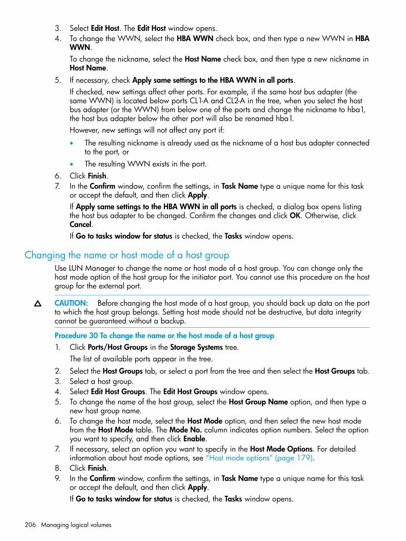
3. Select Edit Host. The Edit Host window opens.4. To change the WWN, select the HBA WWN check box, and then type a new WWN in HBA
WWN.To change the nickname, select the Host Name check box, and then type a new nickname inHost Name.
5. If necessary, check Apply same settings to the HBA WWN in all ports.If checked, new settings affect other ports. For example, if the same host bus adapter (thesame WWN) is located below ports CL1-A and CL2-A in the tree, when you select the hostbus adapter (or the WWN) from below one of the ports and change the nickname to hba1,the host bus adapter below the other port will also be renamed hba1.However, new settings will not affect any port if:
• The resulting nickname is already used as the nickname of a host bus adapter connectedto the port, or
• The resulting WWN exists in the port.6. Click Finish.7. In the Confirm window, confirm the settings, in Task Name type a unique name for this task
or accept the default, and then click Apply.If Apply same settings to the HBA WWN in all ports is checked, a dialog box opens listingthe host bus adapter to be changed. Confirm the changes and click OK. Otherwise, clickCancel.If Go to tasks window for status is checked, the Tasks window opens.
Changing the name or host mode of a host groupUse LUN Manager to change the name or host mode of a host group. You can change only thehost mode option of the host group for the initiator port. You cannot use this procedure on the hostgroup for the external port.
CAUTION: Before changing the host mode of a host group, you should back up data on the portto which the host group belongs. Setting host mode should not be destructive, but data integritycannot be guaranteed without a backup.
Procedure 30 To change the name or the host mode of a host group1. Click Ports/Host Groups in the Storage Systems tree.
The list of available ports appear in the tree.2. Select the Host Groups tab, or select a port from the tree and then select the Host Groups tab.3. Select a host group.4. Select Edit Host Groups. The Edit Host Groups window opens.5. To change the name of the host group, select the Host Group Name option, and then type a
new host group name.6. To change the host mode, select the Host Mode option, and then select the new host mode
from the Host Mode table. The Mode No. column indicates option numbers. Select the optionyou want to specify, and then click Enable.
7. If necessary, select an option you want to specify in the Host Mode Options. For detailedinformation about host mode options, see “Host mode options” (page 179).
8. Click Finish.9. In the Confirm window, confirm the settings, in Task Name type a unique name for this task
or accept the default, and then click Apply.If Go to tasks window for status is checked, the Tasks window opens.
206 Managing logical volumes

Initializing host group 0Use this procedure to set host group 0 (zero) to its initial state. This removes all the WWNs fromhost group 0 and also removes all the LU paths related to host group 0. This procedure also changesthe host mode of host group 0 to Standard and initializes the host group name. For example, ifyou initialize host group 0 for the port CL1-A, the name of host group 0 will change to 1A-G00.Procedure 31 To initialize host group 01. Click Ports/Host Groups in the Storage Systems tree.
The list of available ports appear in the tree.2. Select the Host Groups tab, or select a port from the tree and then select the Host Groups tab.3. Select the host group 0 which is displayed as host group (00).4. On the menu bar, click Actions, Port/Host Group, and then Delete Host Groups. Or, select
Delete Host Groups from the lower right of the window. The Delete Host Groups window opens.5. Confirm the settings and enter the task name in the Task Name box.
A task name can consist of up to 32 ASCII characters (letters, numerals, and symbols). Tasknames are case-sensitive. (date) - (task name) is input by default.
6. Click Apply in the Delete Host Groups window.A message appears, asking whether to delete it.If the Go to tasks window for status check box is selected, the Tasks window appears.
7. Click OK to close the message.
Deleting a host bus adapter from a host group1. Select the Hosts tab in one of the following ways.
• Click Ports/Host Groups in the Storage Systems tree.
• Click Ports/Host Groups in the Storage Systems tree and select a port from the tree.
• Click Ports/Host Groups in the Storage Systems tree and select a port from the tree, andthen select a host group from the tree.
2. Select a host bus adapter.3. Select Remove Hosts.4. In the Remove Hosts window, if necessary, check Remove selected hosts from all host groups
containing the hosts in the storage system.If this check box is selected, selected hosts are removed from all host groups containing thehosts in the storage system.
5. Click Finish.6. In the Confirm window, confirm the settings, in Task Name type a unique name for this task
or accept the default, and then click Apply.A message appears asking whether to delete it.If Go to tasks window for status is checked, the Tasks window opens.
7. Click OK to close the message.
Deleting old WWNs from the WWN tableIf you disconnect a host that has been connected via a cable to your storage system, the WWNfor the host will remain in the WWN list of the LUN Manager window. Use LUN Manager to deletefrom the WWN list a WWN for a host that is no longer connected to your storage system.Procedure 32 To delete old WWNs from the WWN table1. Click Ports/Host Groups in the Storage Systems tree.2. Select the Login WWNs tab.
Managing hosts 207

3. Select the WWNs you want to delete.4. Select Delete Login WWNs. The Delete Login WWNs window opens.5. In the Confirm window, confirm the settings, in Task Name type a unique name for this task
or accept the default, and then click Apply.A message appears asking whether to delete it.If Go to tasks window for status is checked, the Tasks window opens.
6. Click OK to close the message.
Deleting a host groupUse LUN Manager to delete a host group.If host group 0 (zero) is deleted, all WWNs that belong to host group 0 are deleted and all LUpaths that correspond to host group 0 are deleted. The host mode of host group 0 becomesStandard, and the host group name is initialized. To remove all the WWNs and LU paths fromhost group 0, you must initialize host group 0. For details, see “Initializing host group 0” (page 207).Procedure 33 To delete a host group1. Click Ports/Host Groups in the Storage Systems tree.
The list of available ports appear in the tree.2. Select the Host Groups tab, or select a port from the tree and then select the Host Groups tab.3. Select a host group that you want to delete.4. Select Delete Host Groups.5. In the Delete Host Groups window, confirm the settings, in Task Name type a unique name
for this task or accept the default, and then click Apply.If Go to tasks window for status is checked, the Tasks window opens.
6. Click OK to close the message.
208 Managing logical volumes

8 TroubleshootingThe information in this chapter can help you troubleshoot problems when provisioning a storagesystem.If a failure occurs and a message appears, see the HP XP P9000 Remote Web Console Messagesfor further instructions.For problems and solutions related to using Remote Web Console, see the HP XP P9000 RemoteWeb Console User Guide.
Troubleshooting VLLIf a failure occurs while you are operating, see the HP XP P9000 Remote Web Console Messages.For the problems and solutions regarding the Remote Web Console, see the HP XP P9000 RemoteWeb Console User Guide
Troubleshooting Thin ProvisioningThe following table provides troubleshooting instructions for using Thin Provisioning.
Causes and SolutionsProblems
Cause:• Shared memory for the V-VOL management area is not installed.
Solution:
• Call HP Technical Support and check if the shared memory for theV-VOL management area is installed.
Cannot install Thin Provisioning.
Causes:Pool usage level exceeds the threshold.• Too many THP V-VOLs are associated with a pool, or too much data
is stored in a pool.• Capacity of the pool is insufficient.
• The threshold of the pool is too low.
Solutions:
• Add some pool-VOLs to increase the capacity of the pool. See“Increasing pool capacity” (page 152).
• Perform the operation to reclaim zero pages in order to release pagesin which zero data are stored. See “About releasing pages in a THPV-VOL” (page 159).
• Set a larger value to the threshold of the pool. See “Changing poolthresholds” (page 147).
After correcting the causes of SIM 620XXX and 621XXX or 620XXXand 626XXX, you need to complete the SIMs (see “Manually completinga SIM” (page 149)). If you do not complete the SIMs, no new SIM willoccur even if the usage level increases and again exceeds the threshold(target SIM codes are 620XXX, 621XXX, and 626XXX).SIMs 620XXX, 621XXX, 625000, and 626XXX are automaticallycompleted if you increase pool capacity by adding pool-VOLs, becausethe condition that caused the SIM is removed.Caution: You need free volumes to add as pool-VOLs. If there are nofree volumes, create new volumes or ask HP Technical Support to adddrives. Therefore, it may take time to solve the problem.
Troubleshooting VLL 209

Causes and SolutionsProblems
Causes:Cannot create a THP V-VOL.• Usage of the pool has reached to 100%.
• Something in the storage system is blocked.
• Too many THP V-VOLs are assigned, or Subscription Limit is too low.
Solutions:
• Add some pool-VOLs to the pool. See “Increasing pool capacity”(page 152).
• Perform the operation to reclaim zero pages in order to release pagesin which zero data are stored. See “About releasing pages in a THPV-VOL” (page 159).
• Increase the value of Subscription Limit for the pool. See “Changingthe pool subscription limit” (page 148).
• Ask HP Technical Support to solve the problem.
Causes:Cannot add a pool-VOL.• 1,024 pool-VOLs are already defined in the pool.
• The pool-VOL does not fill the requirements for a pool-VOL.
• Something in the storage system is blocked.
Solution:
• Change the setting of the LDEV to satisfy the requirement of thePool-VOL. See “Pool-VOL requirements” (page 76).
Causes:• A failure occurred in two or more data drives.
Solutions:
• Ask HP Technical Support to solve the problem.
A pool-VOL is blocked. SIM code 627XXX isreported.
Causes:• The breaker has been turned off and the shared memory has been
lost, and then the system has been started.Solutions:
• Ask HP Technical Support to solve the problem.
A pool is blocked.
Causes:A pool cannot be restored.• Processing takes time, because something in the storage system is
blocked.• The pool-VOL is blocked.
• The THP V-VOL capacity has increased but has been reduced backto the previous THP V-VOL capacity.
• Usage of the pool has reached to 100%.
Solutions:
• After waiting for a while, click File > Refresh All on the menu bar ofthe Remote Web Console main window, and check the pool status.
• If you increased the THP V-VOL capacity but the THP V-VOL capacityhas been reduced back to the previous THP V-VOL capacity, followthe instructions in “Requirements for increasing THP V-VOL capacity”(page 78) to make sure that the capacity is increased, and thenrestore the pool.
• Add some pool-VOLs to the pool to increase the capacity of the pool.See “Increasing pool capacity” (page 152)).
210 Troubleshooting

Causes and SolutionsProblems
• Perform the operation to reclaim zero pages in order to release pagesin which zero data are stored. See “About releasing pages in a THPV-VOL” (page 159).
• Ask HP Technical Support to solve the problem.
Causes:A pool cannot be deleted.• The pool usage is not 0.
• External volumes are removed from the pool before you delete thepool.
• THP V-VOLs have not been deleted.
Solutions:
• Confirm that the pool usage is 0 after the THP V-VOLs are deleted,and then you can delete the pool.
• Ask HP Technical Support to solve the problem.
Causes:A failure occurs to the application formonitoring the volumes installed in a host. • Free space of the pool is insufficient.
• Something in the storage system is blocked.
Solutions:
• Check the free space of the pool and increase the capacity of thepool. See “Increasing pool capacity” (page 152)).
• Perform the operation to reclaim zero pages in order to release pagesin which zero data are stored. See “About releasing pages in a THPV-VOL” (page 159).
• Ask HP Technical Support to solve the problem.
Causes:When the host computer tries to access theport, error occurs and the host cannot accessthe port.
• Free space of the pool is insufficient.
• Something in the storage system is blocked.
Solutions:
• Check the free space of the pool and increase the capacity of thepool. See “Increasing pool capacity” (page 152).
• Perform the operation to reclaim zero pages in order to release pagesin which zero data are stored. See “About releasing pages in a THPV-VOL” (page 159).
• Ask HP Technical Support to solve the problem.
Causes:When you are operating Remote WebConsole, a timeout occurs frequently. • The load on the Remote Web Console computer is too heavy, so that
the Remote Web Console computer cannot respond to the SVP.• The period of time until when time-out occurs is set too short.
Solutions:
• Wait for a while, then try the operation again.
• Verify the setting of the environment parameter of Remote WebConsole RMI time-out period. For information about how to set theRMI time-out period, see the HP XP P9000 Remote Web ConsoleUser Guide.
See “Troubleshooting provisioning while using RAID Manager” (page 214)and identify the cause.
THP V-VOL capacity cannot be increased.
Solutions:
• After clicking File > Refresh All on the menu bar of the Remote WebConsole main window, confirm whether the processing for increasing
Troubleshooting Thin Provisioning 211

Causes and SolutionsProblems
THP V-VOL capacity meets conditions described in “Requirementsfor increasing THP V-VOL capacity” (page 78).
• Retry the operation after 10 minutes or so.
• Ask HP Technical Support to solve the problem.
Causes:• Zero pages in the THP V-VOL cannot be reclaimed from Remote Web
Console because the THP V-VOL does not meet conditions forreleasing pages in a THP V-VOL.
Solutions:
• Make sure that the THP V-VOL meets the conditions described in“Releasing pages in a THP V-VOL” (page 160).
Cannot reclaim zero pages in a THP V-VOL.
Causes:• Pages of the THP V-VOL are not released because the process of
reclaiming zero pages was interrupted.Solutions:
• Make sure that the THP V-VOL meets the conditions described in“Releasing pages in a THP V-VOL” (page 160).
The THP V-VOL cannot be released if theprocess to reclaim zero pages in the THPV-VOL is interrupted.
Causes:Cannot release the Protection attribute of theTHP V-VOLs. • The pool is full.
• The pool-VOL is blocked.
• The pool-VOL that is an external volume is blocked.
Solutions:
• Add pool-VOLs to the pool to increase the free space in the pool.See “Increasing pool capacity” (page 152).
• Perform the reclaiming zero pages operation to release pages inwhich zero data are stored. See “Releasing pages in a THP V-VOL”(page 160).
• Contact HP Technical Support to restore the pool-VOL.
• If the blocked pool-VOL is an external volume, verify the status of thepath blockade and the external storage system.
• After performing above solutions, release the Protection attribute ofthe THP V-VOLs using the Data Retention window of Remote WebConsole (if the Data Retention is installed). For information aboutData Retention, see the HP XP P9000 Provisioning for Open SystemsUser Guide.
Causes:• Pool usage level exceeds the threshold.
Solutions:
SIM code such as 620XXX, 621XXX, 625000or 626XXX was issued.
• Add pool-VOLs to the pool to increase the free space in the pool.See “Increasing pool capacity” (page 152).
• Perform the operation to reclaim zero pages in order to release pagesin which zero data are stored. See “About releasing pages in a THPV-VOL” (page 159).
212 Troubleshooting
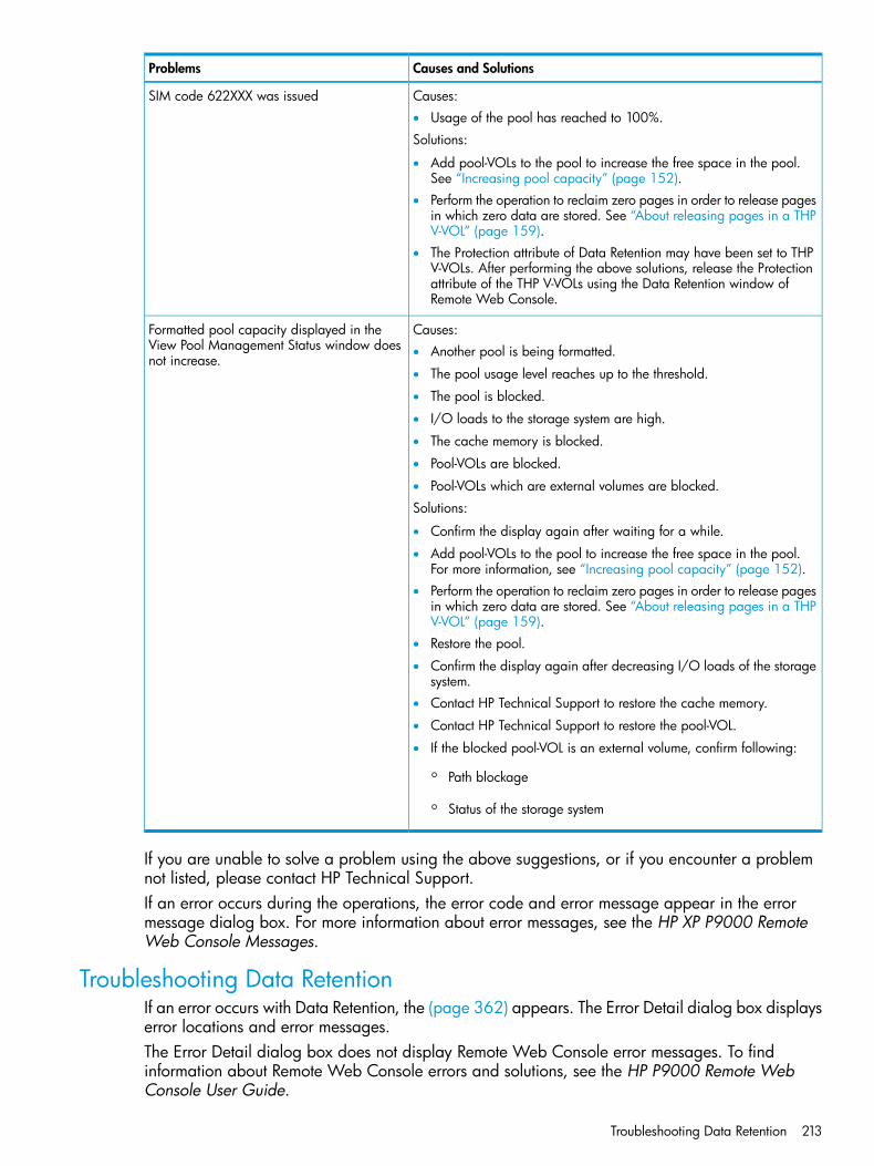
Causes and SolutionsProblems
Causes:• Usage of the pool has reached to 100%.
Solutions:
SIM code 622XXX was issued
• Add pool-VOLs to the pool to increase the free space in the pool.See “Increasing pool capacity” (page 152).
• Perform the operation to reclaim zero pages in order to release pagesin which zero data are stored. See “About releasing pages in a THPV-VOL” (page 159).
• The Protection attribute of Data Retention may have been set to THPV-VOLs. After performing the above solutions, release the Protectionattribute of the THP V-VOLs using the Data Retention window ofRemote Web Console.
Causes:Formatted pool capacity displayed in theView Pool Management Status window doesnot increase.
• Another pool is being formatted.
• The pool usage level reaches up to the threshold.
• The pool is blocked.
• I/O loads to the storage system are high.
• The cache memory is blocked.
• Pool-VOLs are blocked.
• Pool-VOLs which are external volumes are blocked.
Solutions:
• Confirm the display again after waiting for a while.
• Add pool-VOLs to the pool to increase the free space in the pool.For more information, see “Increasing pool capacity” (page 152).
• Perform the operation to reclaim zero pages in order to release pagesin which zero data are stored. See “About releasing pages in a THPV-VOL” (page 159).
• Restore the pool.
• Confirm the display again after decreasing I/O loads of the storagesystem.
• Contact HP Technical Support to restore the cache memory.
• Contact HP Technical Support to restore the pool-VOL.
• If the blocked pool-VOL is an external volume, confirm following:
◦ Path blockage
◦ Status of the storage system
If you are unable to solve a problem using the above suggestions, or if you encounter a problemnot listed, please contact HP Technical Support.If an error occurs during the operations, the error code and error message appear in the errormessage dialog box. For more information about error messages, see the HP XP P9000 RemoteWeb Console Messages.
Troubleshooting Data RetentionIf an error occurs with Data Retention, the (page 362) appears. The Error Detail dialog box displayserror locations and error messages.The Error Detail dialog box does not display Remote Web Console error messages. To findinformation about Remote Web Console errors and solutions, see the HP P9000 Remote WebConsole User Guide.
Troubleshooting Data Retention 213

Data Retention troubleshooting instructionsThe following table provides troubleshooting instructions for using Data Retention.
Probable Causes and SolutionsProblems
If volumes are combined into a LUSE volume, the volume list shows only thetop LDEV of the combined volumes. To view all the volumes combined into aLUSE volume, right-click the volume and then select Volume Detail.
You cannot find some volumes in thelist of the Data Retention window.
You have been making changes in the Data Retention window, but the changeshave not been applied to the storage system. Apply the changes first, andthen perform the extension lock operation.
The Disable/ Enable or theEnable/Disable button on the DataRetention window is unavailable.
You can find the changes by:Nothing happens when you click thebutton.
• scrolling the current list up and down.
• selecting another CU from the tree and then scrolling the list up and down.
Open-systems hosts cannot read fromor write to a volume.
• The volume is protected by the read-only attribute. Write failure is reportedas an error message.
• The volume is protected by the Protect attribute. Read (or write) failure isreported as an error message.
Mainframe hosts cannot read from orwrite to a volume.
• The volume is protected by the read-only attribute. Write failure is reportedas a Write Inhibit condition.
• The volume is protected by the Protect attribute. Read (or write) failure isreported as a cc=3 condition.
The number of days in the Retention Term is calculated based on the operatingtime of the storage system. Therefore, the number of days in the RetentionTerm may not decrease.
The number of days in the RetentionTerm does not decrease
Troubleshooting provisioning while using RAID ManagerIf an error occurs while operating Data Retention or Thin Provisioning while using RAID Manager,you might identify the cause of the error by referring to the log appearing on the RAID Managerwindow or the RAID Manager operation log file.The RAID Manager operation log file is stored in the following directory./HORCM/log*/curlog/horcmlog_HOST/horcm.log
where
• * is the instance number.
• HOST is the host name.The following is an example of a log entry in the RAID Manager window.
Errors when operating RAID Manager (Thin Provisioning, SSB1: 0x2e31/0xb96d)
SolutionsError ContentsError Code (SSB2)
Perform user authentication.The command cannot be executed because userauthentication is not performed.
0x9100
Ask HP Technical Support to solve the problem.Error occurred when increasing THP V-VOLcapacity operation.
0xb900/ 0xb901/0xaf28
214 Troubleshooting
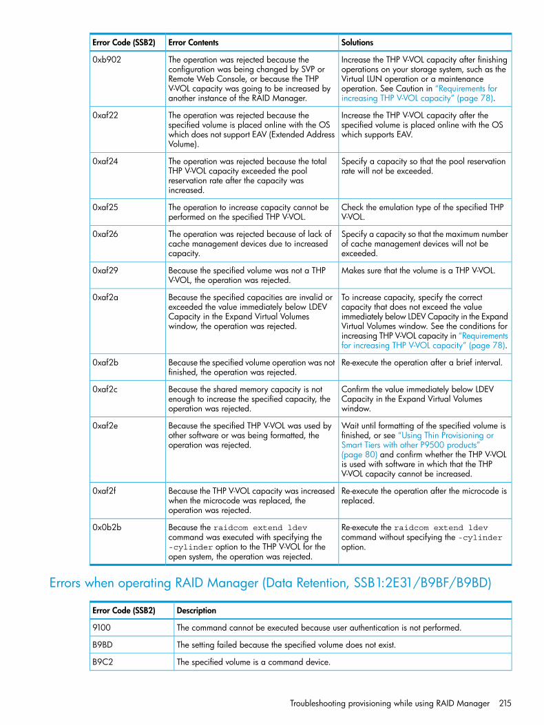
SolutionsError ContentsError Code (SSB2)
Increase the THP V-VOL capacity after finishingoperations on your storage system, such as the
The operation was rejected because theconfiguration was being changed by SVP or
0xb902
Virtual LUN operation or a maintenanceRemote Web Console, or because the THPoperation. See Caution in “Requirements forincreasing THP V-VOL capacity” (page 78).
V-VOL capacity was going to be increased byanother instance of the RAID Manager.
Increase the THP V-VOL capacity after thespecified volume is placed online with the OSwhich supports EAV.
The operation was rejected because thespecified volume is placed online with the OSwhich does not support EAV (Extended AddressVolume).
0xaf22
Specify a capacity so that the pool reservationrate will not be exceeded.
The operation was rejected because the totalTHP V-VOL capacity exceeded the pool
0xaf24
reservation rate after the capacity wasincreased.
Check the emulation type of the specified THPV-VOL.
The operation to increase capacity cannot beperformed on the specified THP V-VOL.
0xaf25
Specify a capacity so that the maximum numberof cache management devices will not beexceeded.
The operation was rejected because of lack ofcache management devices due to increasedcapacity.
0xaf26
Makes sure that the volume is a THP V-VOL.Because the specified volume was not a THPV-VOL, the operation was rejected.
0xaf29
To increase capacity, specify the correctcapacity that does not exceed the value
Because the specified capacities are invalid orexceeded the value immediately below LDEV
0xaf2a
immediately below LDEV Capacity in the ExpandCapacity in the Expand Virtual Volumeswindow, the operation was rejected. Virtual Volumes window. See the conditions for
increasing THP V-VOL capacity in “Requirementsfor increasing THP V-VOL capacity” (page 78).
Re-execute the operation after a brief interval.Because the specified volume operation was notfinished, the operation was rejected.
0xaf2b
Confirm the value immediately below LDEVCapacity in the Expand Virtual Volumeswindow.
Because the shared memory capacity is notenough to increase the specified capacity, theoperation was rejected.
0xaf2c
Wait until formatting of the specified volume isfinished, or see “Using Thin Provisioning or
Because the specified THP V-VOL was used byother software or was being formatted, theoperation was rejected.
0xaf2e
Smart Tiers with other P9500 products”(page 80) and confirm whether the THP V-VOLis used with software in which that the THPV-VOL capacity cannot be increased.
Re-execute the operation after the microcode isreplaced.
Because the THP V-VOL capacity was increasedwhen the microcode was replaced, theoperation was rejected.
0xaf2f
Re-execute the raidcom extend ldevcommand without specifying the -cylinderoption.
Because the raidcom extend ldevcommand was executed with specifying the-cylinder option to the THP V-VOL for theopen system, the operation was rejected.
0x0b2b
Errors when operating RAID Manager (Data Retention, SSB1:2E31/B9BF/B9BD)
DescriptionError Code (SSB2)
The command cannot be executed because user authentication is not performed.9100
The setting failed because the specified volume does not exist.B9BD
The specified volume is a command device.B9C2
Troubleshooting provisioning while using RAID Manager 215

DescriptionError Code (SSB2)
The command was rejected due to one of the following reasons:B9C4• The specified volume is a P-VOL or S-VOL of Snapshot.
• The specified volume is a virtual volume.
• The specified volume is a pool volume.
• The specified volume is an S-VOL of Continuous Access Journal.
• The specified volume is a journal volume.
• The specified volume is reserved for the Auto LUN function.
• The specified volume is a P-VOL or S-VOL of Business Copy.
• The consumed capacity exceeded the licensed capacity.
• The access attribute cannot be changed because the data retention term is set.
• The specified volume is a command device.
• The specified volume is in the PAIR or COPY status.
• The specified volume does not exist.
• The S-VOL Disable attribute is set to the specified volume.
• The reserve function cannot be canceled using RAID Manager.
Data Retention is not installed.B9C7
The consumed capacity exceeded the licensed capacity.B9C9
The command was rejected due to one of the following reasons:B9CA• Fewer days are set as the data retention term.
• More than 60 years are set as the data retention term.
• An interface other than Java updated the settings while Data Retention was in the processof changing them. A conflict occurred between Java and the other interface.
The retention term cannot be set because the access attribute is read/write.B9CB
Calling HP Technical SupportIf you need to call HP Technical Support, make sure you can provide as much information aboutthe problem as possible. Include the circumstances surrounding the error or failure, the RemoteWeb Console configuration information saved by the FD Dump Tool, the exact content of messagesappearing on the Remote Web Console, and severity levels and reference codes appearing onthe Status tab of the Remote Web Console main window (see the HP XP P9000 Remote WebConsole Messages).The HP Technical Support staff is available 24 hours/day, seven days a week. If you need technicalsupport, please call:
• United States: (800) 446-0744
• Outside the United States: (858) 547-4526
216 Troubleshooting

9 Support and other resourcesContacting HP
For worldwide technical support information, see the HP Support Center:http://www.hp.com/go/hpscBefore contacting HP, collect the following information:
• Product model names and numbers
• Technical support registration number (if applicable)
• Product serial numbers
• Error messages
• Operating system type and revision level
• Detailed questions
Subscription serviceReceive, by email, support alerts announcing product support communications, driver updates,software releases, firmware updates, and customer-replaceable component information by signingup at http://www.hp.com/go/myadvisory.To change options for support alerts you already receive, click the Sign in link on the right.
Documentation feedbackHP welcomes your feedback.To make comments and suggestions about product documentation, please send a message [email protected]. Include the document title and manufacturing part number. Allsubmissions become the property of HP.
Related informationThe following documents [and websites] provide related information:
• HP XP P9000 External Storage for Open and Mainframe Systems User Guide
• HP XP P9000 Remote Web Console Messages
• HP XP P9000 Remote Web Console User GuideYou can find these documents on the Manuals page of the HP Business Support Center website:
http://www.hp.com/support/manuals
In the Storage section, click Disk Storage Systems for hardware or Storage Software for software,and then select your product.
HP websitesFor additional information, see the following HP websites:
• http://www.hp.com
• http://www.hp.com/go/storage
• http://www.hp.com/service_locator
• http://www.hp.com/support/manuals
Contacting HP 217

• http://www.hp.com/support/downloads
• http://www.hp.com/storage/whitepapers
Conventions for storage capacity valuesHP XP P9000 disk arrays use the following values to calculate physical storage capacity values(hard disk drives):
• 1 KB (kilobyte) = 1,000 bytes
• 1 MB (megabyte) = 1,0002 bytes
• 1 GB (gigabyte) = 1,0003 bytes
• 1 TB (terabyte) = 1,0004 bytes
• 1 PB (petabyte) = 1,0005 bytes
• 1 EB (exabyte) = 1,0006 bytesHP XP P9000 disk arrays use the following values to calculate logical storage capacity values(logical devices):
• 1 KB (kilobyte) = 1,024 bytes
• 1 MB (megabyte) = 1,0242 bytes
• 1 GB (gigabyte) = 1,0243 bytes
• 1 TB (terabyte) = 1,0244 bytes
• 1 PB (petabyte) = 1,0245 bytes
• 1 EB (exabyte) = 1,0246 bytes
Typographic conventionsTable 2 Document conventions
ElementConvention
Blue text: Table 2 (page 218) • Cross-reference links and e-mail addresses
• A cross reference to the glossary definition of the termin blue text
email addressesBlue, bold, underlined text
Website addressesBlue, underlined text: http://www.hp.com
Bold text • Keys that are pressed
• Text typed into a GUI element, such as a box
• GUI elements that are clicked or selected, such as menuand list items, buttons, tabs, and check boxes
Text emphasisItalic text
Monospace text • File and directory names
• System output
• Code
• Commands, their arguments, and argument values
Monospace, italic text • Code variables
• Command variables
Emphasized monospace textMonospace, bold text
218 Support and other resources

WARNING! Indicates that failure to follow directions could result in bodily harm or death.
CAUTION: Indicates that failure to follow directions could result in damage to equipment or data.
IMPORTANT: Provides clarifying information or specific instructions.
NOTE: Provides additional information.
TIP: Provides helpful hints and shortcuts.
Typographic conventions 219

A RAID Manager command referenceThis appendix provides information on Remote Web Console tasks and corresponding RAIDManager commands used in provisioning.
Remote Web Console tasks and RAID Manager command listThe following lists actions (tasks) that can be performed in the Remote Web Console GUI, and thecorresponding commands that can be issued in RAID Manager.
RAID Manager commandAction nameItem
raidcom add ldevCreate LDEVsLogical Device
raidcom delete ldevDelete LDEVs
raidcom modify ldevEdit LDEVs
raidcom initialize ldevFormat LDEVs
raidcom modify ldevBlock LDEVs
raidcom modify ldevRestore LDEVs
raidcom modify ldevAssign MP Blade
raidcom add lunAdd LUN Paths
raidcom delete lunDelete LUN Paths
raidcom extend ldevExpand V-VOLs
raidcom modify ldevReclaim Zero Pages
raidcom initialize ldevShredding
raidcom add host_grpCreate Host GroupsPort/Host Group
raidcom delete host_grpDelete Host Groups
raidcom modify host_grpEdit Host Groups
raidcom add hba_wwnAdd Hosts
raidcom add hba_wwnAdd to Host Groups
raidcom delete hba_wwnRemove Hosts
raidcom add hba_wwnEdit Host
raidcom add lunCreate Alternate LUN Paths
raidcom modify portEdit Ports
raidcom add thp_poolCreate PoolsPool
raidcom add thp_poolExpand Pool
raidcom delete poolShrink pools
raidcom delete poolDelete Pools
raidcom modify poolEdit Pools
raidcom monitor poolMonitor Pools
raidcom monitor poolStop Monitoring Pools
raidcom reallocate poolStart Tier Relocation
raidcom reallocate poolStop Tier Relocation
220 RAID Manager command reference

RAID Manager commandAction nameItem
raidcom modify poolRestore Pools
raidcom get thp_poolView Tier Properties
raidcom disconnect external_grpDisconnect External VolumesExternal Storage
raidcom check_ext_storageReconnect External Volumes
Remote Web Console tasks and RAID Manager command list 221
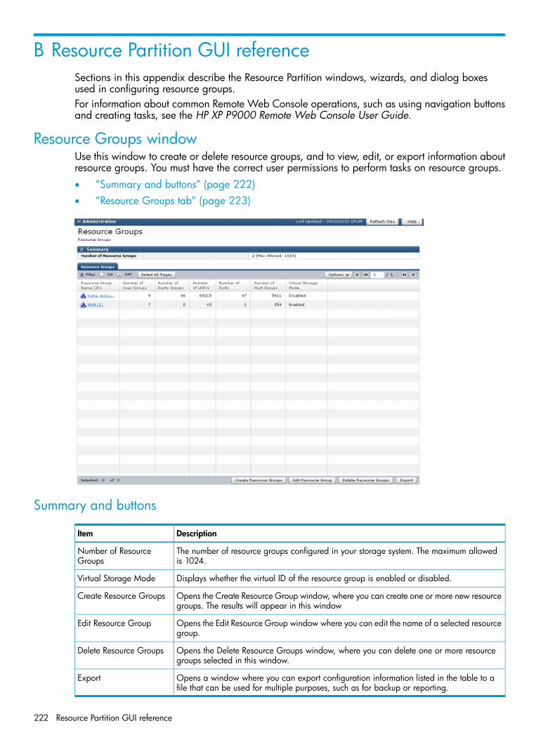
B Resource Partition GUI referenceSections in this appendix describe the Resource Partition windows, wizards, and dialog boxesused in configuring resource groups.For information about common Remote Web Console operations, such as using navigation buttonsand creating tasks, see the HP XP P9000 Remote Web Console User Guide.
Resource Groups windowUse this window to create or delete resource groups, and to view, edit, or export information aboutresource groups. You must have the correct user permissions to perform tasks on resource groups.• “Summary and buttons” (page 222)• “Resource Groups tab” (page 223)
Summary and buttons
DescriptionItem
The number of resource groups configured in your storage system. The maximum allowedis 1024.
Number of ResourceGroups
Displays whether the virtual ID of the resource group is enabled or disabled.Virtual Storage Mode
Opens the Create Resource Group window, where you can create one or more new resourcegroups. The results will appear in this window
Create Resource Groups
Opens the Edit Resource Group window where you can edit the name of a selected resourcegroup.
Edit Resource Group
Opens the Delete Resource Groups window, where you can delete one or more resourcegroups selected in this window.
Delete Resource Groups
Opens a window where you can export configuration information listed in the table to afile that can be used for multiple purposes, such as for backup or reporting.
Export
222 Resource Partition GUI reference
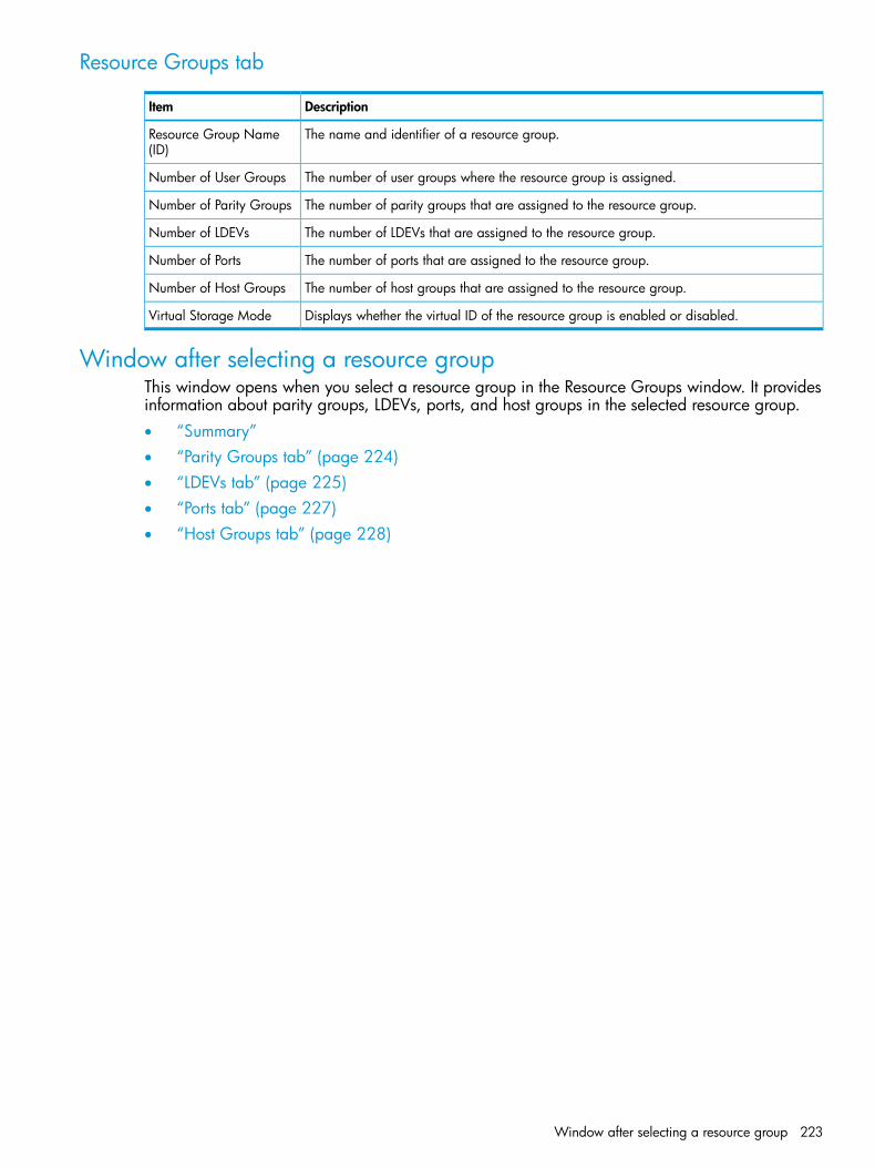
Resource Groups tab
DescriptionItem
The name and identifier of a resource group.Resource Group Name(ID)
The number of user groups where the resource group is assigned.Number of User Groups
The number of parity groups that are assigned to the resource group.Number of Parity Groups
The number of LDEVs that are assigned to the resource group.Number of LDEVs
The number of ports that are assigned to the resource group.Number of Ports
The number of host groups that are assigned to the resource group.Number of Host Groups
Displays whether the virtual ID of the resource group is enabled or disabled.Virtual Storage Mode
Window after selecting a resource groupThis window opens when you select a resource group in the Resource Groups window. It providesinformation about parity groups, LDEVs, ports, and host groups in the selected resource group.• “Summary”• “Parity Groups tab” (page 224)• “LDEVs tab” (page 225)• “Ports tab” (page 227)• “Host Groups tab” (page 228)
Window after selecting a resource group 223

Summary
DescriptionItem
The number of parity groups that are assigned to the resource group.Number of Parity Groups
The number of LDEVs that are assigned to the resource group.Number of LDEVs
The number of ports that are assigned to the resource group.Number of Ports
The number of host groups that are assigned to the resource group.Number of Host Groups
Parity Groups tab
DescriptionItem
Identifiers of parity groups that are already defined.Parity Group ID
The capacity of each parity group.Capacity
The number of LDEVs in each parity group.Number of LDEVs
Opens the Add Resources window, where you can add one or more resources to theresource group.
Add Resources
224 Resource Partition GUI reference

DescriptionItem
Opens the Remove Resources window, where you can remove one or more resources fromthe resource group.
Remove Resources
Opens a window where you can export configuration information listed in the table to afile that can be used for multiple purposes, such as backup or reporting.
Export
LDEVs tab
DescriptionItem
The LDEV identifiers.LDEV IDSome undefined LDEV IDs may appear. A hyphen appearing in the LDEV name indicatesthe LDEV is undefined.
The LDEV name.LDEV Name
The parity group identifier in which the LDEV belongs.Parity Group ID
The pool name and identifier in which the LDEV belongs.Pool Name (ID)
The capacity of each LDEV.Capacity
Window after selecting a resource group 225

DescriptionItem
The provisioning type of each volume.Provisioning Type• Basic: Internal volume
• THP: V-VOLs of Thin Provisioning or Thin Provisioning Z
• External: External volume
• Snapshot: Fast Snap volume or Snapshot volume
• External MF: Migration volume
The attribute of the volume indicating how the LDEV is being used.Attribute• Command Device: Command device.
• Remote Command Device.
• System Disk.
• JNL VOL: Journal volume.
• Pool VOL: Pool volume. The number in parentheses is the pool identifier.
• Reserved VOL: Reserved volume.
• Quorum Disk: Quorum disk for External Storage Access Manager.
• TSE: TSE-VOL.
• Online Data Migration: Volume for online data migration.
• Hyphen (-): Volume in which the attribute is not defined.
The journal group identifier when the attribute is JNL VOL. A hyphen indicates the attributeis other than JNL VOL.
Journal Group ID
Opens the Add Resources window, where you can add one or more resources to theresource group.
Add Resources
Opens the Remove Resources window, where you can remove one or more resources fromthe resource group.
Remove Resources
Opens a window where you can export configuration information listed in the table to afile that can be used for multiple purposes, such as backup or reporting.
Export
226 Resource Partition GUI reference
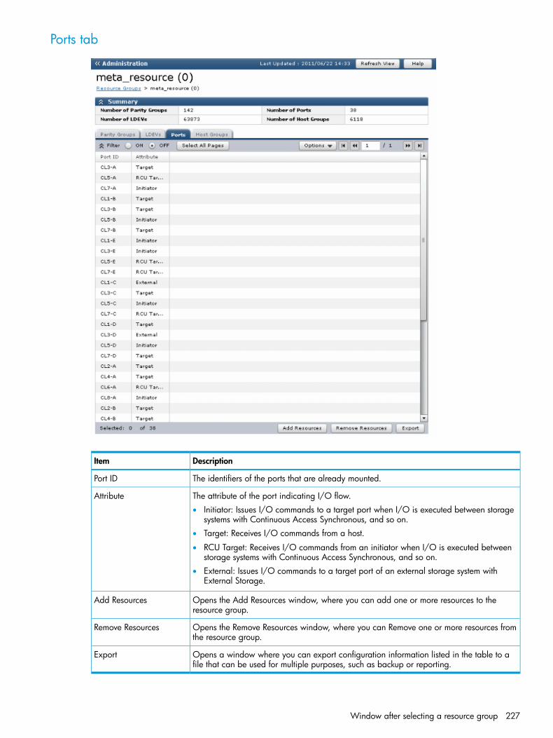
Ports tab
DescriptionItem
The identifiers of the ports that are already mounted.Port ID
The attribute of the port indicating I/O flow.Attribute• Initiator: Issues I/O commands to a target port when I/O is executed between storage
systems with Continuous Access Synchronous, and so on.• Target: Receives I/O commands from a host.
• RCU Target: Receives I/O commands from an initiator when I/O is executed betweenstorage systems with Continuous Access Synchronous, and so on.
• External: Issues I/O commands to a target port of an external storage system withExternal Storage.
Opens the Add Resources window, where you can add one or more resources to theresource group.
Add Resources
Opens the Remove Resources window, where you can Remove one or more resources fromthe resource group.
Remove Resources
Opens a window where you can export configuration information listed in the table to afile that can be used for multiple purposes, such as backup or reporting.
Export
Window after selecting a resource group 227
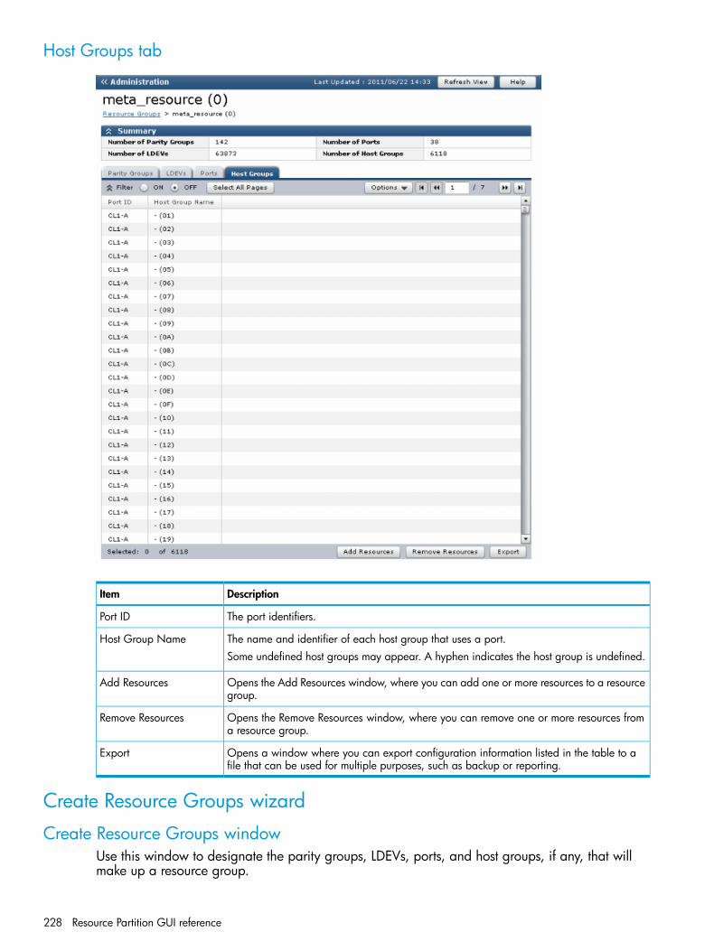
Host Groups tab
DescriptionItem
The port identifiers.Port ID
The name and identifier of each host group that uses a port.Host Group NameSome undefined host groups may appear. A hyphen indicates the host group is undefined.
Opens the Add Resources window, where you can add one or more resources to a resourcegroup.
Add Resources
Opens the Remove Resources window, where you can remove one or more resources froma resource group.
Remove Resources
Opens a window where you can export configuration information listed in the table to afile that can be used for multiple purposes, such as backup or reporting.
Export
Create Resource Groups wizard
Create Resource Groups windowUse this window to designate the parity groups, LDEVs, ports, and host groups, if any, that willmake up a resource group.
228 Resource Partition GUI reference

Setting fields
DescriptionItem
Enter a unique name for this resource group. the following rules apply:Resource Group Name• meta_resource cannot be set as a resource group name.
• Names should be unique, and multiple occurrences of the same resource groupname are not allowed in one storage system.
• Resource names are case-sensitive.
• Usable characters are alphanumeric, spaces, and symbols (! # $ % & ' ( ) + - . = @[ ] ^ _ ` { } ~)
Opens the Select Parity Groups window, where you select one or more parity groupsto be assigned to the resource group.
Select Parity Groups
Opens the Select LDEVs window, where you select one or more LDEVs to be assignedto the resource group.
Select LDEVs
Opens the Select Ports window, where you select one or more ports to be assigned tothe resource group.
Select Ports
Create Resource Groups wizard 229

DescriptionItem
Opens the Select Host Groups window, where you select one or more host groups tobe assigned to the resource group.
Select Host Groups
Adds your settings to the Selected Resource Groups table.Add
Selected Resource Groups table
DescriptionItem
The name and identifier of each resource group.Resource Group Name (ID)A hyphen indicates the ID number is not assigned before setting a resource group.
The number of parity groups to be assigned to the resource group.Number of Parity Groups
The number of LDEVs to be assigned to the resource group.Number of LDEVs
The number of ports to be assigned to the resource group.Number of Ports
The number of host groups to be assigned to the resource group.Number of Host Groups
Opens the Resource Group Property window, where you can view details of the selectedresource group.
Detail
Removes a selected resource group.Remove
230 Resource Partition GUI reference
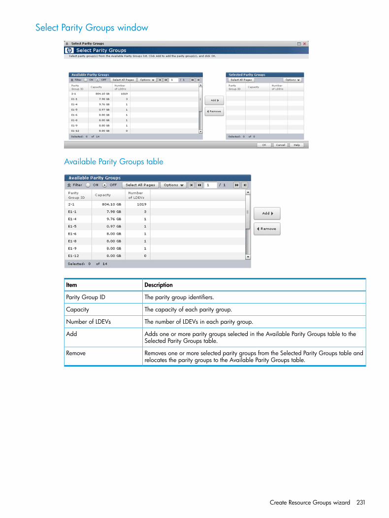
Select Parity Groups window
Available Parity Groups table
DescriptionItem
The parity group identifiers.Parity Group ID
The capacity of each parity group.Capacity
The number of LDEVs in each parity group.Number of LDEVs
Adds one or more parity groups selected in the Available Parity Groups table to theSelected Parity Groups table.
Add
Removes one or more selected parity groups from the Selected Parity Groups table andrelocates the parity groups to the Available Parity Groups table.
Remove
Create Resource Groups wizard 231

Selected Parity Groups table
DescriptionItem
The parity group identifiers.Parity Group ID
The capacity of each parity group.Capacity
The number of LDEVs in each parity group.Number of LDEVs
Select LDEVs window
Available LDEVs table
DescriptionItem
The LDEV identifiers.LDEV ID
232 Resource Partition GUI reference

DescriptionItem
LDEV IDs may be appear for undefined LDEVs. A hyphen appearing in columns to theright of the LDEV ID and LDEV name (for example, Parity Group ID, Pool Name ID,Capacity, and so on) indicates the LDEV is undefined.
The LDEV names.LDEV Name
The parity group identifier where the LDEV belongs.Parity Group ID
The pool name and identifier where the LDEV belongs.Pool Name (ID)
The capacity of each LDEV.Capacity
The provisioning type of each volume.Provisioning Type• Basic: Internal volume
• THP: V-VOLs of Thin Provisioning or Thin Provisioning Z
• External: External volume
• Snapshot: Fast Snap volume or Snapshot volume
The attribute of the volume indicating how the LDEV is used.Attribute• Command Device: Command device
• Remote Command Device: Remote command device
• System Disk: System disk
• JNL VOL: Journal volume
• Pool VOL: Pool volume. The number in parentheses shows the pool ID.
• Reserved VOL: Reserved volume
• Quorum Disk: Quorum disk for External Storage Access Manager.
• TSE: TSE-VOL
• Online Data Migration: Volume for online data migration
• Hyphen (-): Volume in which the attribute is not defined
The journal group identifier when the attribute is JNL VOL. A hyphen indicates theattribute is other than JNL VOL.
Journal Group ID
Adds one or more LDEVs selected in the Available LDEVs table to the Selected LDEVstable.
Add
Removes one or more selected LDEVs from the Selected LDEVs table and relocates theLDEVs to the Available LDEVs table.
Remove
Create Resource Groups wizard 233

Selected LDEVs table
DescriptionItem
The LDEV identifiers.LDEV IDSome undefined LDEV IDs may appear. A hyphen in the LDEV name indicates the LDEVis undefined.
The LDEV names.LDEV Name
The parity group identifier where the LDEV belongs.Parity Group ID
The pool name and identifier where the LDEV belongs.Pool Name (ID)
The capacity of the LDEV.Capacity
Displays the type of each volume.Provisioning Type• Basic: Internal volume
• THP: V-VOLs of Thin Provisioning
• External: External volume
• Snapshot: Fast Snap volume or Snapshot volume
• External MF: Migration volume
The attribute of the volume indicating how the LDEV is being used.Attribute• Command Device: Command device.
• Remote Command Device.
• System Disk.
• JNL VOL: Journal volume.
• Pool VOL: Pool volume. The number in parentheses is the pool identifier.
• Reserved VOL: Reserved volume.
• Quorum Disk: Quorum disk for External Storage Access Manager.
• TSE: TSE-VOL.
• Online Data Migration: Volume for online data migration.
• Hyphen (-): Volume in which the attribute is not defined.
The journal group identifier when the attribute is JNL VOL. A hyphen indicates theattribute is other than JNL VOL.
Journal Group ID
234 Resource Partition GUI reference
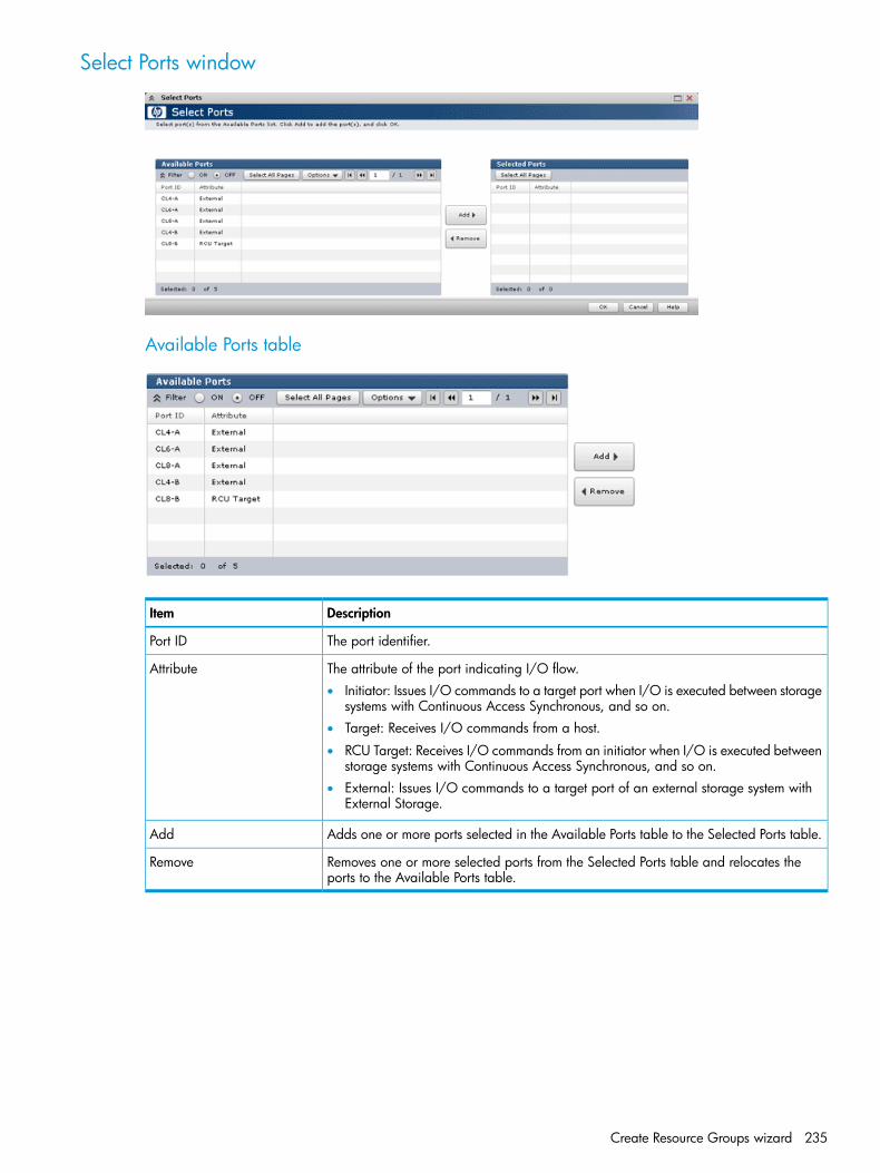
Select Ports window
Available Ports table
DescriptionItem
The port identifier.Port ID
The attribute of the port indicating I/O flow.Attribute• Initiator: Issues I/O commands to a target port when I/O is executed between storage
systems with Continuous Access Synchronous, and so on.• Target: Receives I/O commands from a host.
• RCU Target: Receives I/O commands from an initiator when I/O is executed betweenstorage systems with Continuous Access Synchronous, and so on.
• External: Issues I/O commands to a target port of an external storage system withExternal Storage.
Adds one or more ports selected in the Available Ports table to the Selected Ports table.Add
Removes one or more selected ports from the Selected Ports table and relocates theports to the Available Ports table.
Remove
Create Resource Groups wizard 235

Selected Ports table
DescriptionItem
The port identifier.Port ID
The attribute of the port indicating I/O flow.Attribute• Initiator: Issues I/O commands to a target port when I/O is executed between storage
systems with Continuous Access Synchronous, and so on.• Target: Receives I/O commands from a host.
• RCU Target: Receives I/O commands from an initiator when I/O is executed betweenstorage systems with Continuous Access Synchronous, and so on.
• External: Issues I/O commands to a target port of an external storage system withExternal Storage.
Select Host Groups window
236 Resource Partition GUI reference
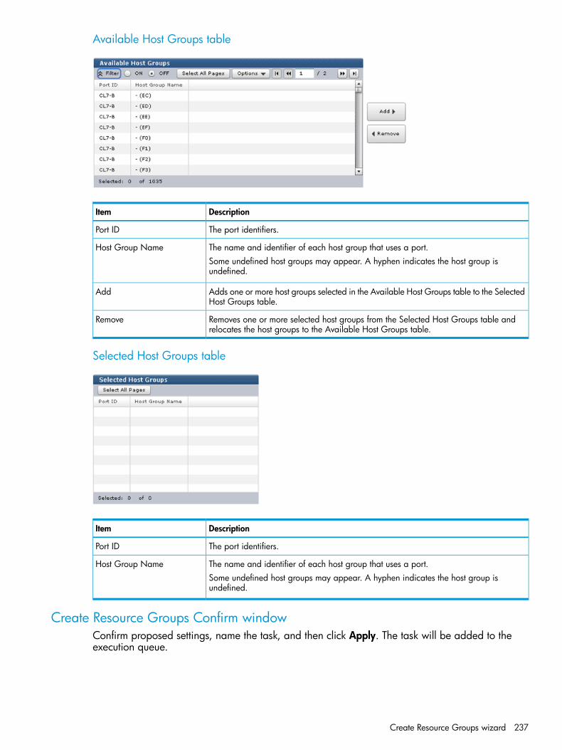
Available Host Groups table
DescriptionItem
The port identifiers.Port ID
The name and identifier of each host group that uses a port.Host Group NameSome undefined host groups may appear. A hyphen indicates the host group isundefined.
Adds one or more host groups selected in the Available Host Groups table to the SelectedHost Groups table.
Add
Removes one or more selected host groups from the Selected Host Groups table andrelocates the host groups to the Available Host Groups table.
Remove
Selected Host Groups table
DescriptionItem
The port identifiers.Port ID
The name and identifier of each host group that uses a port.Host Group NameSome undefined host groups may appear. A hyphen indicates the host group isundefined.
Create Resource Groups Confirm windowConfirm proposed settings, name the task, and then click Apply. The task will be added to theexecution queue.
Create Resource Groups wizard 237

DescriptionItem
The name and identifier of each resource group.Resource Group Name (ID)
The number of parity groups to be assigned to the resource group.Number of Parity Groups
The number of LDEVs to be assigned to the resource group.Number of LDEVs
The number of ports to be assigned to the resource group.Number of Ports
The number of host groups to be assigned to the resource group.Number of Host Groups
Opens the Resource Group Property window, where you can view the details of theselected resource group.
Detail
Edit Resource Group wizard
Edit Resource Group window
DescriptionItem
The type the name of the resource group after editing.Resource Group Name• meta_resource cannot be set as a name.
• Duplicate occurrences of the same resource group name are not allowed in onestorage system.
• Names are case-sensitive.
• Usable characters are alphanumeric, spaces, and symbols (! # $ % & ' ( ) + - . = @[ ] ^ _ ` { } ~)
238 Resource Partition GUI reference

DescriptionItem
Edit Resource Group Confirm windowConfirm proposed settings, name the task, and then click Apply. The task will be added to theexecution queue.
Selected Resource Group tab
DescriptionItem
The name and identifier of the edited resource group.Resource Group Name (ID)
The number of parity groups that are assigned to the resource group.Number of Parity Groups
The number of LDEVs that are assigned to the resource group.Number of LDEVs
The number of ports that are assigned to the resource group.Number of Ports
The number of host groups that are assigned to the resource group.Number of Host Groups
Opens the Resource Group Property window, where you can view the details of theselected resource group.
Detail
Edit Resource Group wizard 239

Add Resources wizard
Add Resources window
DescriptionItem
Opens the Select Parity Group window, where you can select one or more parity groupsto be added to the resource group.
Select Parity Groups
Opens the Select LDEVs window, where you can select one or more LDEVs to be addedto the resource group.
Select LDEVs
Opens the Select Ports window, where you can select one or more ports to be addedto the resource group.
Select Ports
Opens the Select Host group window, where you can select one or more host groupsto be added to the resource group.
Select Host Groups
Add Resources Confirm windowConfirm proposed settings, name the task, and then click Apply. The task will be added to theexecution queue.
240 Resource Partition GUI reference

Selected Resource Group table
DescriptionItem
The name and identifier of the resource group to be added to the storage system.Resource Group Name (ID)
Selected Parity Groups table
DescriptionItem
The parity group identifiers to be added to the resource group.Parity Group ID
The capacity of each parity group.Capacity
The number of LDEVs in each parity group.Number of LDEVs
The total number of selected parity groups.Total
Add Resources wizard 241

Selected LDEVs table
DescriptionItem
The identifiers of the LDEVs to be added to a resource group.LDEV IDSome undefined LDEV IDs may appear. A hyphen in the LDEV name indicates the LDEVis undefined.
The LDEV names.LDEV Name
The parity group identifier where the LDEV belongs.Parity Group ID
The pool name and identifier where the LDEV belongs.Pool Name (ID)
The capacity of the LDEV.Capacity
The provisioning type of the volume.Provisioning Type• Basic: Internal volume
• THP: V-VOLs of Thin Provisioning
• Snapshot: Fast Snap volume or Snapshot volume
• External MF: Migration volume
The attribute of the volume indicating how the LDEV is being used.Attribute• Command Device: Command device.
• Remote Command Device.
• System Disk.
• JNL VOL: Journal volume.
• Pool VOL: Pool volume. The number in parentheses is the pool identifier.
• Reserved VOL: Reserved volume.
• Quorum Disk: Quorum disk for External Storage Access Manager.
• TSE: TSE-VOL.
• Online Data Migration: Volume for online data migration.
• Hyphen (-): Volume in which the attribute is not defined.
The journal group identifier appears when the attribute is JNL VOL. A hyphen indicatesthe attribute is other than JNL VOL.
Journal Group ID
The total number of selected LDEVs.Total
Selected Ports table
DescriptionItem
Port identifiers to be added to a resource group.Port ID
Attribute of the port indicating I/O flow.Attribute• Initiator: Issues I/O commands to a target port when I/O is executed between storage
systems with Continuous Access Synchronous, and so on.• Target: Receives I/O commands from a host.
• RCU Target: Receives I/O commands from an initiator when I/O is executed betweenstorage systems with Continuous Access Synchronous, and so on.
• External: Issues I/O commands to a target port of an external storage system withExternal Storage.
Total number of selected ports.Total
242 Resource Partition GUI reference

Selected Host Groups table
DescriptionItem
The port identifiers that are used by the host group.Port ID
The name and identifier of each host group to be added to a resource group.Host Group NameSome undefined host groups may appear. A hyphen indicates the host group isundefined.
The total number of selected host groups.Total
Remove Resources window
Selected Resource Group table
DescriptionItem
The name and identifier of each resource group whose resources are deleted.Resource Group Name (ID)
Selected Parity Groups table (when deleting parity groups)
DescriptionItem
The identifier of each parity group to be deleted from the resource group.Parity Group ID
The capacity of each parity group.Capacity
The number of LDEVs in the parity group.Number of LDEVs
The total number of parity groups.Total
Selected LDEVs table (when deleting LDEVs)
DescriptionItem
The LDEV identifiers to be deleted from a resource group.LDEV ID
Remove Resources window 243

DescriptionItem
Some undefined LDEV IDs may appear. A hyphen in the LDEV name indicates the LDEVis undefined.
The LDEV names to be deleted from the resource group.LDEV Name
The parity group ID where the LDEV belongs.Parity Group ID
The pool name where the LDEV belongs.Pool Name (ID)
The capacity of each LDEV.Capacity
The provisioning type of each volume.Provisioning Type• Basic: Internal volume
• THP: V-VOLs of Thin Provisioning or Thin Provisioning Z
• External: External volume
• BC/SS: Fast Snap volume or Snapshot volume
• External MF: Migration volume
The attribute of the volume indicating how the LDEV is being used.Attribute• Command Device: Command device.
• Remote Command Device.
• System Disk.
• JNL VOL: Journal volume.
• Pool VOL: Pool volume. The number in parentheses is the pool identifier.
• Reserved VOL: Reserved volume.
• Quorum Disk: Quorum disk for External Storage Access Manager.
• TSE: TSE-VOL.
• Online Data Migration: Volume for online data migration.
• Hyphen (-): Volume in which the attribute is not defined.
The journal group ID when the attribute is JNL VOL. A hyphen indicates the attribute isother than JNL VOL.
Journal Group ID
The total number of selected LDEVs.Total
Selected Ports table (when deleting ports)
DescriptionItem
The port IDs that to be deleted from the resource group.Port ID
The attribute of the port indicating I/O flow.Attribute• Initiator: Issues I/O commands to a target port when I/O is executed between storage
systems with Continuous Access Synchronous, and so on.• Target: Receives I/O commands from a host.
• RCU Target: Receives I/O commands from an initiator when I/O is executed betweenstorage systems with Continuous Access Synchronous, and so on.
• External: Issues I/O commands to a target port of an external storage system withExternal Storage.
Total number of selected ports.Total
244 Resource Partition GUI reference
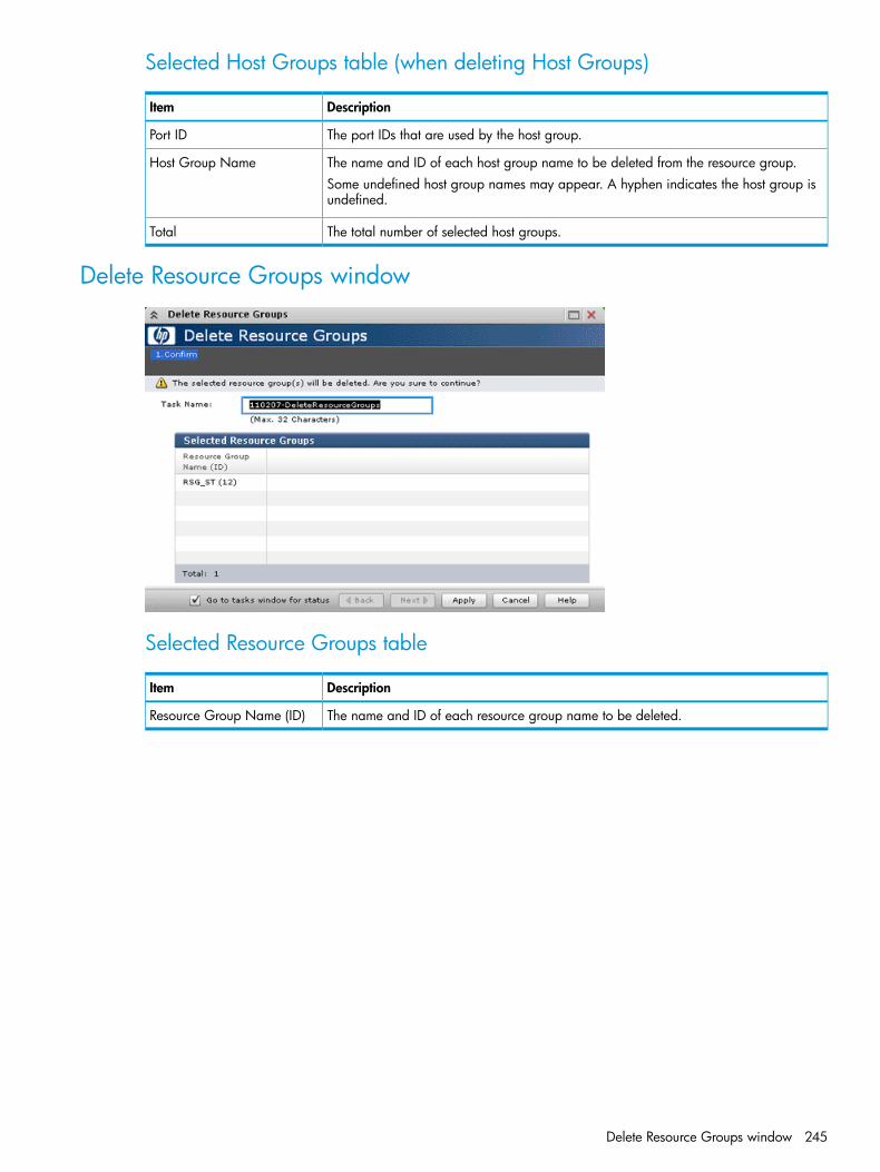
Selected Host Groups table (when deleting Host Groups)
DescriptionItem
The port IDs that are used by the host group.Port ID
The name and ID of each host group name to be deleted from the resource group.Host Group NameSome undefined host group names may appear. A hyphen indicates the host group isundefined.
The total number of selected host groups.Total
Delete Resource Groups window
Selected Resource Groups table
DescriptionItem
The name and ID of each resource group name to be deleted.Resource Group Name (ID)
Delete Resource Groups window 245

Resource Group Properties window
Resource Group Properties table
DescriptionItem
The name and ID of a resource group name.Resource Group Name (ID)
The number of parity groups that are assigned to the resource group.Number of Parity Groups
The number of LDEVs that are assigned to the resource group.Number of LDEVs
The number of ports that are assigned to the resource group.Number of Ports
The number of host groups that are assigned to the resource group.Number of Host Groups
246 Resource Partition GUI reference

Parity Groups table
DescriptionItem
The parity group IDs.Parity Group ID
The capacity of each parity group.Capacity
The number of LDEVs in each parity group.Number of LDEVs
Displays the attribute of the parity group.Attribute• Online Data Migration: Parity group for online data migration.
• -: Parity group in which the attribute is not defined.
The total number of selected parity groups.Total
LDEVs table
DescriptionItem
The LDEV IDs.LDEV IDSome undefined LDEV IDs may appear. A hyphen in the LDEV name indicates the LDEVis undefined.
The LDEV names.LDEV Name
The parity group ID where the LDEV belongs.Parity Group ID
The pool name and ID where the LDEV belongs.Pool Name (ID)
The capacity of each LDEV.Capacity
The provisioning type of a volume.Provisioning Type• Basic: Internal volume
• THP: V-VOLs of Thin Provisioning
• Snapshot: Fast Snap volume or Snapshot volume
• External: External volume
• External MF: External volume
The attribute of the volume indicating how the LDEV is being used.Attribute• Command Device: Command device.
• Remote Command Device.
• System Disk.
• JNL VOL: Journal volume.
• Pool VOL: Pool volume. The number in parentheses is the pool identifier.
• Reserved VOL: Reserved volume.
• Quorum Disk: Quorum disk for External Storage Access Manager.
• TSE: TSE-VOL.
• Online Data Migration: Volume for online data migration.
• Hyphen (-): Volume in which the attribute is not defined.
The journal group ID when the attribute is JNL VOL. A hyphen indicates the attribute isother than JNL VOL.
Journal Group ID
The total number of selected volumes.Total
Resource Group Properties window 247

Ports table
DescriptionItem
The port IDs.Port Name
Displays the attribute of each port. Initiator, Target, RCU Target, or External is displayed.Attribute
The total number of selected ports.Total
Host Groups table
DescriptionItem
The port IDs that are used by the host group.Port ID
The name and ID of each host group.Host Group NameSome undefined host group names may appear. A hyphen indicates the host group isundefined.
The total number of selected host groups.Total
248 Resource Partition GUI reference

C LDEV GUI referenceSections in this appendix describe the windows, wizards, and dialog boxes used in creating LDEVs.For information about common Remote Web Console operations, such as using navigation buttonsand creating tasks, see the HP XP P9000 Remote Web Console User Guide.
Parity Groups windowUse this window to view information about parity groups. Only the parity groups assigned to thelogged-on user are available.• “Summary”• “Parity Groups tab”
Summary
DescriptionItem
The capacity of all of the parity groups in the internal volume.Capacity - Internal• Free1: Free space capacity of the internal volume.
• Total2: Total capacity of the internal volume.
The capacity of all of the parity groups in the external volume.Capacity - External• Free1: Free space capacity of the external volume.
• Total2: Total capacity of the external volume.
Notes:1. The control information, such as control cylinders, used by the storage system is not included in the Free space.2. The total capacity of the LDEVs and Free capacity is displayed in the Total.
Parity Groups window 249

Parity Groups tab
DescriptionItem
The parity group identifier of the parity group in the storage system.Parity Group ID
The status of each LDEV in the parity group.LDEV Status
Normal: Normal status.
Blocked: Host cannot access a blocked volume.
Warning: Problem occurs in the volume.
Formatting: Volume is being formatted.
Preparing Quick Format: Volume is being prepared for quick formatting.
Quick Formatting: Volume is being quick-formatted.
Correction Access: Access attribute is being corrected.
Copying: Data in the volume is being copied.
Read Only: Data cannot be written on a read-only volume.
Shredding: Volume is being shredded.
Hyphen (-): Any status other than the above.
The RAID level. An asterisk "*" indicates that the parity group to which the LDEVbelongs is interleaved (concatenated). Either RAID level of the parity groupappears.
RAID Level
The emulation type of each parity group.Base Emulation Type
The capacity of the free space of each parity group. The control information,such as control cylinders, used by the storage system is not included in thedisplayed capacity.
Capacity - Free
The total capacity of the LDEVs and "Capacity - Free" is displayed.Capacity - Total
The number of unallocated LDEVs in each parity group.Number of LDEVs - Unallocated
The total number of LDEVs in each parity group.Number of LDEVs - Total
The drive type and rpm in use on this LDEV.Drive Type/RPM
The protection status on the parity group.Protection• SATA-W/V, SATA-E, or Standard.
• Standard is for SAS, SSD, and External.
The encryption key information.Encryption Key• Key identifier for the encrypted parity group, and
• Disable for the non-encrypted parity group.
Displays the attribute of the parity group.AttributeOnline Data Migration: Parity group for online data migration.Hyphen (-): The parity group in which the attribute is not defined.
The resource group name and ID of which this parity group is a member.Resource Group Name (ID)
Opens the Create LDEVs window.Create LDEVs
Opens the Format LDEVs window.Format LDEVs
250 LDEV GUI reference

DescriptionItem
Opens the Edit Encryption window.Edit Encryption
Opens a window where you can export configuration information listed in thetable to a file that can be used for multiple purposes, such as backup or reporting.
Export
Parity Groups window after selecting Internal (or External) under ParityGroups
Use this window to view information about the parity groups in the internal (or external) volume.Only the parity groups assigned to the logged-on user are available.• “Summary”• “Parity Groups tab”
Summary
DescriptionItem
The free space capacity of the internal (or external) volume. The controlinformation, such as control cylinders, used by the storage system is not includedin the displayed capacity.
Capacity - Free
The total capacity of the LDEVs and "Capacity - Free" is displayed.Capacity - Total
Parity Groups window after selecting Internal (or External) under Parity Groups 251
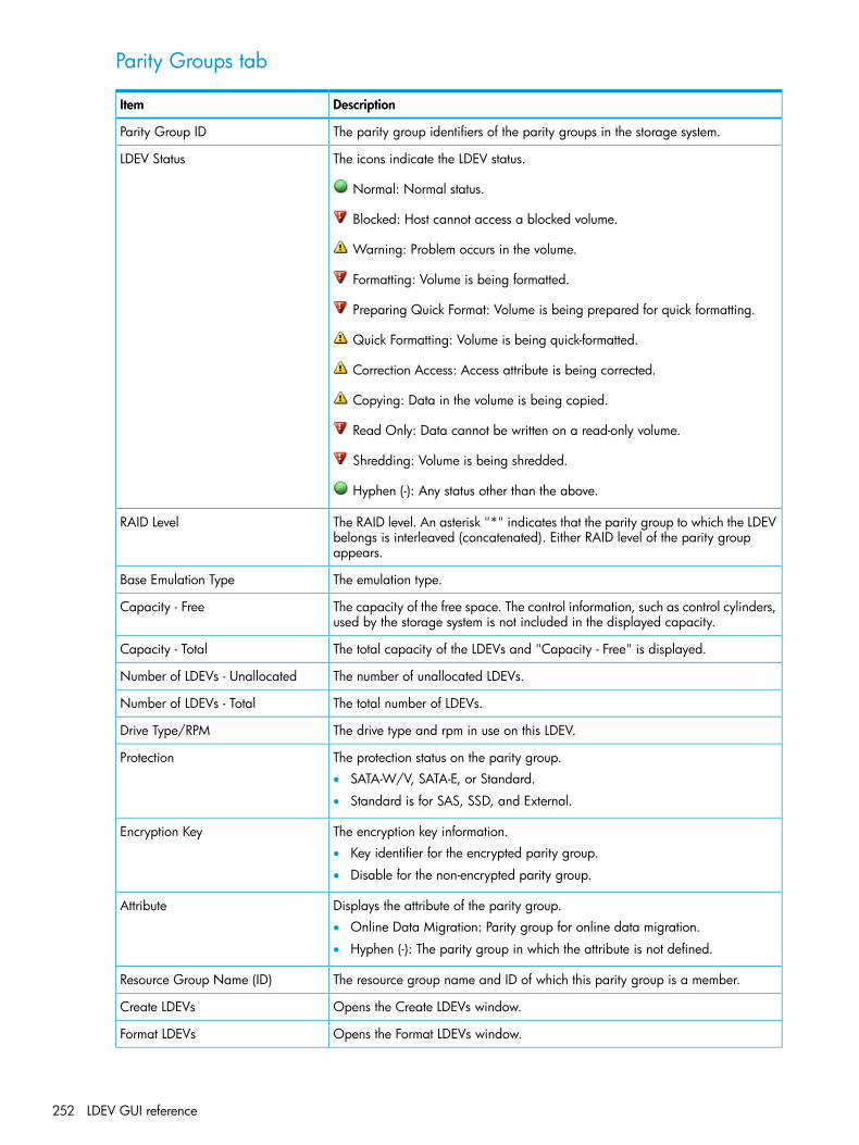
Parity Groups tab
DescriptionItem
The parity group identifiers of the parity groups in the storage system.Parity Group ID
The icons indicate the LDEV status.LDEV Status
Normal: Normal status.
Blocked: Host cannot access a blocked volume.
Warning: Problem occurs in the volume.
Formatting: Volume is being formatted.
Preparing Quick Format: Volume is being prepared for quick formatting.
Quick Formatting: Volume is being quick-formatted.
Correction Access: Access attribute is being corrected.
Copying: Data in the volume is being copied.
Read Only: Data cannot be written on a read-only volume.
Shredding: Volume is being shredded.
Hyphen (-): Any status other than the above.
The RAID level. An asterisk "*" indicates that the parity group to which the LDEVbelongs is interleaved (concatenated). Either RAID level of the parity groupappears.
RAID Level
The emulation type.Base Emulation Type
The capacity of the free space. The control information, such as control cylinders,used by the storage system is not included in the displayed capacity.
Capacity - Free
The total capacity of the LDEVs and "Capacity - Free" is displayed.Capacity - Total
The number of unallocated LDEVs.Number of LDEVs - Unallocated
The total number of LDEVs.Number of LDEVs - Total
The drive type and rpm in use on this LDEV.Drive Type/RPM
The protection status on the parity group.Protection• SATA-W/V, SATA-E, or Standard.
• Standard is for SAS, SSD, and External.
The encryption key information.Encryption Key• Key identifier for the encrypted parity group.
• Disable for the non-encrypted parity group.
Displays the attribute of the parity group.Attribute• Online Data Migration: Parity group for online data migration.
• Hyphen (-): The parity group in which the attribute is not defined.
The resource group name and ID of which this parity group is a member.Resource Group Name (ID)
Opens the Create LDEVs window.Create LDEVs
Opens the Format LDEVs window.Format LDEVs
252 LDEV GUI reference

DescriptionItem
Opens the Edit Encryption window.Edit Encryption
Opens a window where you can export configuration information listed in thetable to a file that can be used for multiple purposes, such as backup or reporting.
Export
Window after selecting a parity group under Internal (or External) of ParityGroups
Use this window to view information about the parity groups in the internal (or external) volume.Only the parity groups assigned to the logged-on user are available.• “Summary”• “LDEVs tab”
Summary
DescriptionItem
The current status of the LDEV.LDEV Status
Normal: Normal status.
Blocked: Host cannot access a blocked volume.
Warning: Problem occurs in the volume.
Formatting: Volume is being formatted.
Preparing Quick Format: Volume is being prepared for quick formatting.
Quick Formatting: Volume is being quick-formatted.
Window after selecting a parity group under Internal (or External) of Parity Groups 253
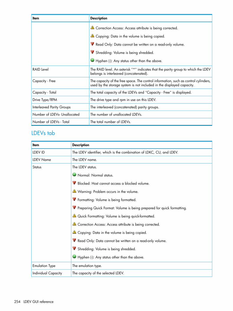
DescriptionItem
Correction Access: Access attribute is being corrected.
Copying: Data in the volume is being copied.
Read Only: Data cannot be written on a read-only volume.
Shredding: Volume is being shredded.
Hyphen (-): Any status other than the above.
The RAID level. An asterisk "*" indicates that the parity group to which the LDEVbelongs is interleaved (concatenated).
RAID Level
The capacity of the free space. The control information, such as control cylinders,used by the storage system is not included in the displayed capacity.
Capacity - Free
The total capacity of the LDEVs and "Capacity - Free" is displayed.Capacity - Total
The drive type and rpm in use on this LDEV.Drive Type/RPM
The interleaved (concatenated) parity groups.Interleaved Parity Groups
The number of unallocated LDEVs.Number of LDEVs- Unallocated
The total number of LDEVs.Number of LDEVs - Total
LDEVs tab
DescriptionItem
The LDEV identifier, which is the combination of LDKC, CU, and LDEV.LDEV ID
The LDEV name.LDEV Name
The LDEV status.Status
Normal: Normal status.
Blocked: Host cannot access a blocked volume.
Warning: Problem occurs in the volume.
Formatting: Volume is being formatted.
Preparing Quick Format: Volume is being prepared for quick formatting.
Quick Formatting: Volume is being quick-formatted.
Correction Access: Access attribute is being corrected.
Copying: Data in the volume is being copied.
Read Only: Data cannot be written on a read-only volume.
Shredding: Volume is being shredded.
Hyphen (-): Any status other than the above.
The emulation type.Emulation Type
The capacity of the selected LDEV.Individual Capacity
254 LDEV GUI reference

DescriptionItem
The attribute of the volume indicating how the LDEV is being used.Attribute• Command Device: The volume is a command device.
• Remote Command Device: The volume is a remote command device.
• System Disk: The volume is a system disk.
• JNL VOL: The volume is a journal volume.
• Pool VOL: The volume is a pool volume. The number in the parenthesis indicates the poolidentifier.
• Reserved VOL: The volume is a reserved volume.
• Quorum Disk: The volume is a quorum disk for External Storage Access Manager.
• Online Data Migration: Volume for online data migration.
• TSE: TSE-VOL
• Hyphen (-): Volume in which the attribute is not defined
The resource group name and identifier of the LDEV.Resource Group Name(ID)
Opens the Create LDEVs window.Create LDEVs
Opens the Edit LDEVs window.Edit LDEVs
Opens the Format LDEVs window.Format LDEVs
Opens the Delete LDEVs window.Delete LDEVs*
Opens the Shred LDEVs window.Shred LDEVs*
Opens the Block LDEVs window.Block LDEVs*
Opens the Restore LDEVs window.Restore LDEVs*
Opens a window where you can export configuration information listed in the table to a filethat can be used for multiple purposes, such as backup or reporting.
Export
*Available when you click More Actions.
Window after selecting Logical DevicesUse this window to view information about logical devices. Only the LDEVS assigned to thelogged-on user are available.• “Summary”• “LDEVs tab”
Window after selecting Logical Devices 255

Summary
DescriptionItem
The number of allocated LDEVs for open system.Number of LDEVs - Open Allocated
The number of unallocated LDEVs for open system.Number of LDEVs - OpenUnallocated
The number of reserved LDEVs for the open system.Number of LDEVs - Open Reserved
The number of allocated V-VOLs for the open system.Number of LDEVs - Open V-VOLs
The number of allocated LDEVs for the mainframe system.Number of LDEVs - MainframeAllocated
The number of reserved LDEVs for the mainframe system.Number of LDEVs - MainframeReserved
The number of allocated V-VOLs for the mainframe system.Number of LDEVs - MainframeV-VOLs
The total number of LDEVs.Total Number of LDEVs
LDEVs tab
DescriptionItem
The LDEV identifier, which is the combination of LDKC, CU, and LDEV.LDEV ID
The LDEV name.LDEV Name
The LDEV status.Status
Normal: Normal status.
256 LDEV GUI reference
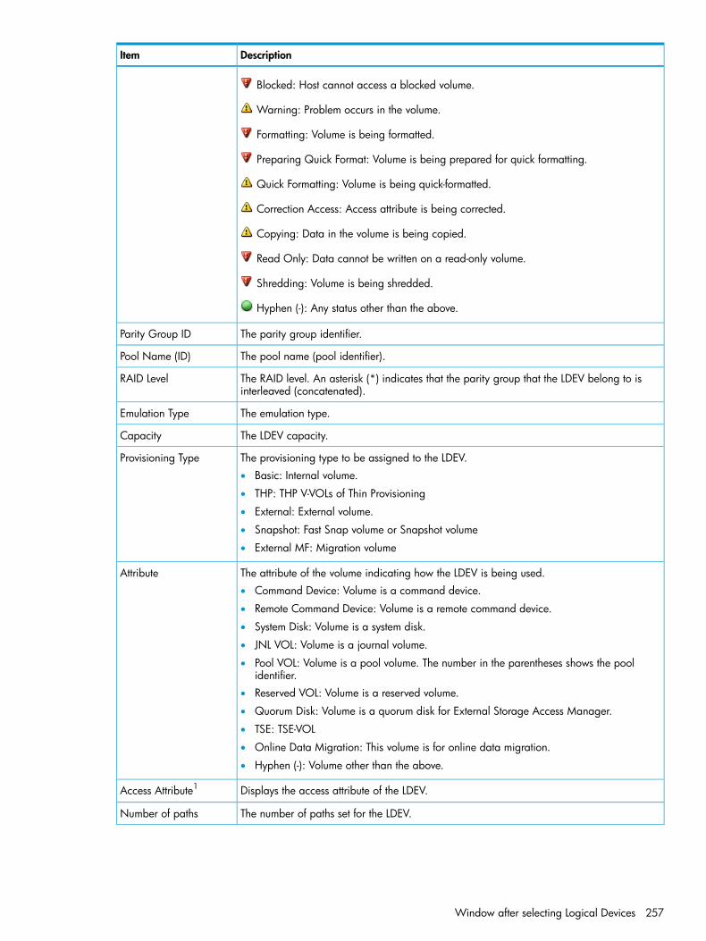
DescriptionItem
Blocked: Host cannot access a blocked volume.
Warning: Problem occurs in the volume.
Formatting: Volume is being formatted.
Preparing Quick Format: Volume is being prepared for quick formatting.
Quick Formatting: Volume is being quick-formatted.
Correction Access: Access attribute is being corrected.
Copying: Data in the volume is being copied.
Read Only: Data cannot be written on a read-only volume.
Shredding: Volume is being shredded.
Hyphen (-): Any status other than the above.
The parity group identifier.Parity Group ID
The pool name (pool identifier).Pool Name (ID)
The RAID level. An asterisk (*) indicates that the parity group that the LDEV belong to isinterleaved (concatenated).
RAID Level
The emulation type.Emulation Type
The LDEV capacity.Capacity
The provisioning type to be assigned to the LDEV.Provisioning Type• Basic: Internal volume.
• THP: THP V-VOLs of Thin Provisioning
• External: External volume.
• Snapshot: Fast Snap volume or Snapshot volume
• External MF: Migration volume
The attribute of the volume indicating how the LDEV is being used.Attribute• Command Device: Volume is a command device.
• Remote Command Device: Volume is a remote command device.
• System Disk: Volume is a system disk.
• JNL VOL: Volume is a journal volume.
• Pool VOL: Volume is a pool volume. The number in the parentheses shows the poolidentifier.
• Reserved VOL: Volume is a reserved volume.
• Quorum Disk: Volume is a quorum disk for External Storage Access Manager.
• TSE: TSE-VOL
• Online Data Migration: This volume is for online data migration.
• Hyphen (-): Volume other than the above.
Displays the access attribute of the LDEV.Access Attribute1
The number of paths set for the LDEV.Number of paths
Window after selecting Logical Devices 257

DescriptionItem
Displays the V-VOL management task being performed on a Thin Provisioning, ThinProvisioning Z, Smart Tiers, or a Smart Tiers Z V-VOL.
V-VOL Management Task
• Reclaiming Zero Pages: The process is in progress.
• Waiting for Zero Page Reclaiming: The process has been waited.
• Hyphen (-): The process is not being performed on the LDEV.
The processor blade identifier.MP Blade ID Processor
The resource group name and ID of which this LDEV is a member.Resource Group Name(ID)
Opens the Create LDEVs window.Create LDEVs
Opens the LUN Paths window.Add LUN Paths
Opens the Edit LDEVs window.Edit LDEVs
Opens the Format LDEVs window.Format LDEVs2
Opens the Delete LDEVs window.Delete LDEVs2
Opens the Shred LDEVs window.Shred LDEVs2
Opens the Delete LUN Paths window.Delete LUN Paths2
Opens the Edit Command Devices windowEdit Command Device
Opens the Block LDEVs window.Block LDEVs2
Opens the Restore LDEVs window.Restore LDEVs2
Opens the Assign Processor Blade window.Assign MP Blade2
Opens the Delete UUIDs window.Delete UUIDs2
Opens the Reclaim Zero Pages window.Reclaim Zero Pages2
Opens the Stop Reclaiming Zero Pages window.Stop Reclaiming ZeroPages2
Opens the Expand V-VOLs window.Expand V-VOLs2
Opens a window where you can export configuration information listed in the table to a filethat can be used for multiple purposes, such as backup or reporting.
Export2
1Does not appear by default. To display this item, change the Column Settings of the table option. For details aboutthe Column Settings window, see the HP P9000 Remote Web Console User Guide.2Appears when you click More Actions.
Create LDEVs wizardUse this window to create and provision LDEVs. You can create multiple LDEVs at once when settingup your storage system. After the storage system is in operation, use this window to create additionalLDEVs as needed.
Create LDEVs window• “Setting fields”• “Selected LDEVs table”
258 LDEV GUI reference
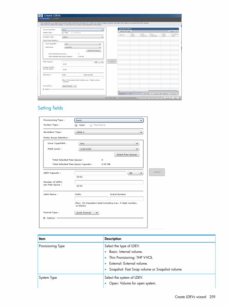
Setting fields
DescriptionItem
Select the type of LDEV.Provisioning Type• Basic: Internal volume.
• Thin Provisioning: THP V-VOL.
• External: External volume.
• Snapshot: Fast Snap volume or Snapshot volume
Select the system of LDEV.System Type• Open: Volume for open system.
Create LDEVs wizard 259
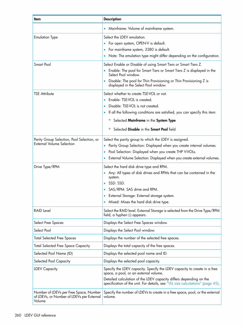
DescriptionItem
• Mainframe: Volume of mainframe system.
Select the LDEV emulation.Emulation Type• For open system, OPEN-V is default.
• For mainframe system, 3380 is default.
• Note: The emulation type might differ depending on the configuration.
Select Enable or Disable of using Smart Tiers or Smart Tiers Z.Smart Pool• Enable: The pool for Smart Tiers or Smart Tiers Z is displayed in the
Select Pool window.• Disable: The pool for Thin Provisioning or Thin Provisioning Z is
displayed in the Select Pool window.
Select whether to create TSE-VOL or not.TSE Attribute• Enable: TSE-VOL is created.
• Disable: TSE-VOL is not created.
• If all the following conditions are satisfied, you can specify this item:
◦ Selected Mainframe in the System Type
◦ Selected Disable in the Smart Pool field
Select the parity group to which the LDEV is assigned.Parity Group Selection, Pool Selection, orExternal Volume Selection • Parity Group Selection: Displayed when you create internal volumes.
• Pool Selection: Displayed when you create THP V-VOLs.
• External Volume Selection: Displayed when you create external volumes.
Select the hard disk drive type and RPM.Drive Type/RPM• Any: All types of disk drives and RPMs that can be contained in the
system.• SSD: SSD.
• SAS/RPM: SAS drive and RPM.
• External Storage: External storage system.
• Mixed: Mixes the hard disk drive type.
Select the RAID level. External Storage is selected from the Drive Type/RPMfield, a hyphen (-) appears.
RAID Level
Displays the Select Free Spaces window.Select Free Spaces
Displays the Select Pool window.Select Pool
Displays the number of the selected free spaces.Total Selected Free Spaces
Displays the total capacity of the free spaces.Total Selected Free Space Capacity
Displays the selected pool name and ID.Selected Pool Name (ID)
Displays the selected pool capacity.Selected Pool Capacity
Specify the LDEV capacity. Specify the LDEV capacity to create in a freespace, a pool, or an external volume.
LDEV Capacity
Detailed calculation of the LDEV capacity differs depending on thespecification of the unit. For details, see “VLL size calculations” (page 45).
Specify the number of LDEVs to create in a free space, pool, or the externalvolume.
Number of LDEVs per Free Space, Numberof LDEVs, or Number of LDEVs per ExternalVolume
260 LDEV GUI reference

DescriptionItem
LDEV name. Specify the prefix characters and the initial number.LDEV NamePrefix is a fixed character string.Initial Number is the initial number of the LDEV name.Specify the prefix characters and the initial number according to the rulesbelow. You can specify up to 32 characters total.Example:
• 1: Up to 9 numbers are added (1, 2, 3... 9).
• 08: Up to 92 numbers are added (08, 09, 10... 99).
• 23: Up to 77 numbers are added (23, 24, 25... 99).
• 098: Up to 902 numbers are added (098, 099, 100... 999).
Specify the format type. This appears when an internal or external volumeis used.
Format Type
Quick Format: Quick formatting is the default format type. You cannotselect this when the provisioning type is something other than the internalvolume.Write to Control Blocks: You can select this option when the externalmainframe volume is created. This is default when selecting the externalvolume of the mainframe system.Normal Format: Normal formatting.No Format: Volumes are not formatted.
Specify the LDEV ID. LDKC is fixed to 00. Default of CU and DEV is 00:00.Initial LDEV IDFor creating multiple LDEVs, select the interval of the assigned LDEV IDfrom the Interval list.
Displays the View LDEV IDs windows.View LDEV IDs
Specify the SSID. The default is 0004.Initial SSIDWhen creating multiple LDEVs, specify the beginning number setting tothe LDEV.
Displays the View SSIDs window.View SSIDs
The cache logical partition number, displayed as ID:CLPR.CLPR
Specify the processor blade you want to assign to the LDEV.Processor BladeYou can select an ID from MPB0 to MPB7. If automatic assignment isenabled for one or more processors, you can also select Auto.If Auto is enabled, the default is Auto. If Auto is disabled, the default isthe lowest number of the processor blade.
The tiering policy: All(0) is selected by default. You can change a levelfrom Level1(1) to Level5(5) or from Level6(6) to Level31(31). See “Noteson tiering policy settings” (page 114).
Tiering Policy
You can specify this function when the Smart Pool is enabled.
Specify the new page assignment tier you want to assign to the LDEV.Middle is selected by default. You can select from the levels of High,
New Page Assignment Tier
Middle, and Low. See New “New page assignment tier” (page 115). Youcan specify this function when the Multi-Tier Pool is enabled.
Specify this option if the LDEV is to be relocated preferentially. You canselect Default or Prioritize.
Relocation Priority
You can specify this function when the Smart Pool is enabled.
Create LDEVs wizard 261

DescriptionItem
Select this option when creating LDEVs as the system disk.Create LDEVs as System Disk
Adds the LDEVs that have settings specified in the setting field is added tothe Selected LDEVs table.
Add
The items that can be set in this window depend on the type of volume you are creating. Thefollowing table lists the items that can be set according to volume type.
Snapshotvolume
Externalvolume
V-VOL formainframesystem
V-VOL foropen system
Internal volumeItem
RequiredRequiredRequiredRequiredRequiredProvisioning Type
RequiredRequiredRequiredRequiredRequiredSystem Type
RequiredRequiredRequiredRequiredRequiredEmulation Type
N/AN/ARequiredRequiredN/ASmart Pool
N/AN/ARequiredDisabledN/ATSE Attribute
N/ADisabledRequiredRequiredRequiredDrive Type/RPM
N/ADisabledRequiredRequiredRequiredRAID Level
N/ARequiredN/AN/ARequiredSelect Free Spaces
N/AN/ARequiredRequiredN/ASelect Pool
RequiredRequiredRequiredRequiredRequiredLDEV Capacity
N/AN/AN/AN/ARequiredNumber of LDEVs per Free Space
RequiredN/ARequiredRequiredN/ANumber of LDEVs
N/ARequiredN/AN/AN/ANumber of LDEVs per ExternalVolume
OptionalOptionalOptionalOptionalOptionalLDEV Name
N/ARequiredN/AN/ARequiredFormat Type
OptionalOptionalOptionalOptionalOptionalInitial LDEV ID
OptionalOptionalOptionalOptionalOptionalView LDEV IDs
OptionalOptionalOptionalOptionalOptionalInitial SSID
OptionalOptionalOptionalOptionalOptionalView SSIDs
OptionalN/AOptionalOptionalN/ACLPR
OptionalOptionalOptionalOptionalOptionalProcessor Blade
N/AN/AOptionalOptionalN/ATiering Policy
N/AN/AOptionalOptionalN/ANew Page Assignment Tier
N/AN/AOptionalOptionalN/ARelocation Priority
N/AOptionalN/AN/AOptionalCreate LDEVs as System Disk
262 LDEV GUI reference

Selected LDEVs table
DescriptionItem
The LDEV identifier, which is the combination of LDKC, CU, and LDEV.LDEV ID
The LDEV name, including the combination of prefix characters and theinitial number.
LDEV Name
The parity group identifier.Parity Group ID
The pool name and pool identifier.Pool Name (ID)
The drive type and rpm in use on this LDEV.Drive Type/RPM
The RAID level. An asterisk "*" indicates that the parity group to whichthe LDEV belongs is interleaved (concatenated).
RAID Level
The emulation type.Emulation Type
The LDEV capacity.Capacity
The format type.Format Type
The storage system identifier in hexadecimal format.SSID
The cache logical partition number, displayed as ID:CLPR.CLPRFor detailed information about CLPRs, see the HP XP P9000 Cache PartitionUser Guide.
The processor blade identifier. If Auto is selected, the ID is automaticallyassigned.
MP Blade ID
Indicates whether the LDEV is being used as the system disk.System Disk• Yes: System disk.
• No: Not system disk.
Indicates whether Smart Tiers or Smart Tiers Z is enabled or disabled.Smart Pool• Enable: The LDEV is for Smart Tiers or Smart Tiers Z.
• Disable: The LDEV is for Smart Tiers or Smart Tiers Z.
Create LDEVs wizard 263
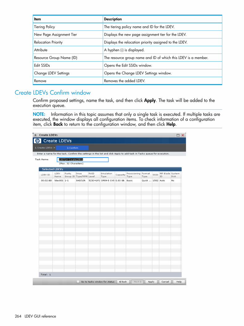
DescriptionItem
The tiering policy name and ID for the LDEV.Tiering Policy
Displays the new page assignment tier for the LDEV.New Page Assignment Tier
Displays the relocation priority assigned to the LDEV.Relocation Priority
A hyphen (-) is displayed.Attribute
The resource group name and ID of which this LDEV is a member.Resource Group Name (ID)
Opens the Edit SSIDs window.Edit SSIDs
Opens the Change LDEV Settings window.Change LDEV Settings
Removes the added LDEV.Remove
Create LDEVs Confirm windowConfirm proposed settings, name the task, and then click Apply. The task will be added to theexecution queue.
NOTE: Information in this topic assumes that only a single task is executed. If multiple tasks areexecuted, the window displays all configuration items. To check information of a configurationitem, click Back to return to the configuration window, and then click Help.
264 LDEV GUI reference

Selected LDEVs table
DescriptionItem
The LDEV identifier, which is the combination of LDKC, CU, and LDEV.LDEV ID
The LDEV name, including the combination of prefix characters and theinitial number.
LDEV Name
The parity group identifier.Parity Group ID
The pool name (pool identifier).Pool Name (ID)
The drive type and rpm in use on this LDEV.Drive Type/RPM
The RAID level. An asterisk "*" indicates that the parity group to whichthe LDEV belongs is interleaved (concatenated).
RAID Level
The emulation type.Emulation Type
The LDEV capacity.Capacity
The type of LDEV.Provisioning Type• Basic: Internal volume.
• THP: THP V-VOL.
• External: External volume.
• Snapshot: Fast Snap volume or Snapshot volume.
The format type.Format Type
The storage system identifier in hexadecimal format.SSID
The cache logical partition number, in ID:CLPR format.CLPRFor detailed information about CLPRs, see the HP XP P9000 Cache PartitionUser Guide.
The processor blade identifier. If Auto is selected, the ID is automaticallyassigned.
MP Blade ID
The indicates whether the LDEV is being used as the system disk.System Disk• Yes: System disk.
• No: Not system disk.
Displays whether Smart Tiers or Smart Tiers Z is enabled or disabled.Smart Pool• Enable: The LDEV for Smart Tiers or Smart Tiers Z is displayed.
• Disable: The LDEV for Thin Provisioning or Thin Provisioning Z isdisplayed.
Displays the tiering policy name and ID for the LDEV.Tiering Policy
Displays the new page assignment tier for the LDEV.New Page Assignment Tier
The relocation priority assigned to the LDEV.Relocation Priority
Displays the attribute of the LDEV.Attribute• TSE: TSE-VOL.
• -: Volume in which attribute is not defined.
The resource group name and ID of which this LDEV is a member.Resource Group Name (ID)
Edit LDEVs wizardUse this window to change the LDEV name.
Edit LDEVs wizard 265
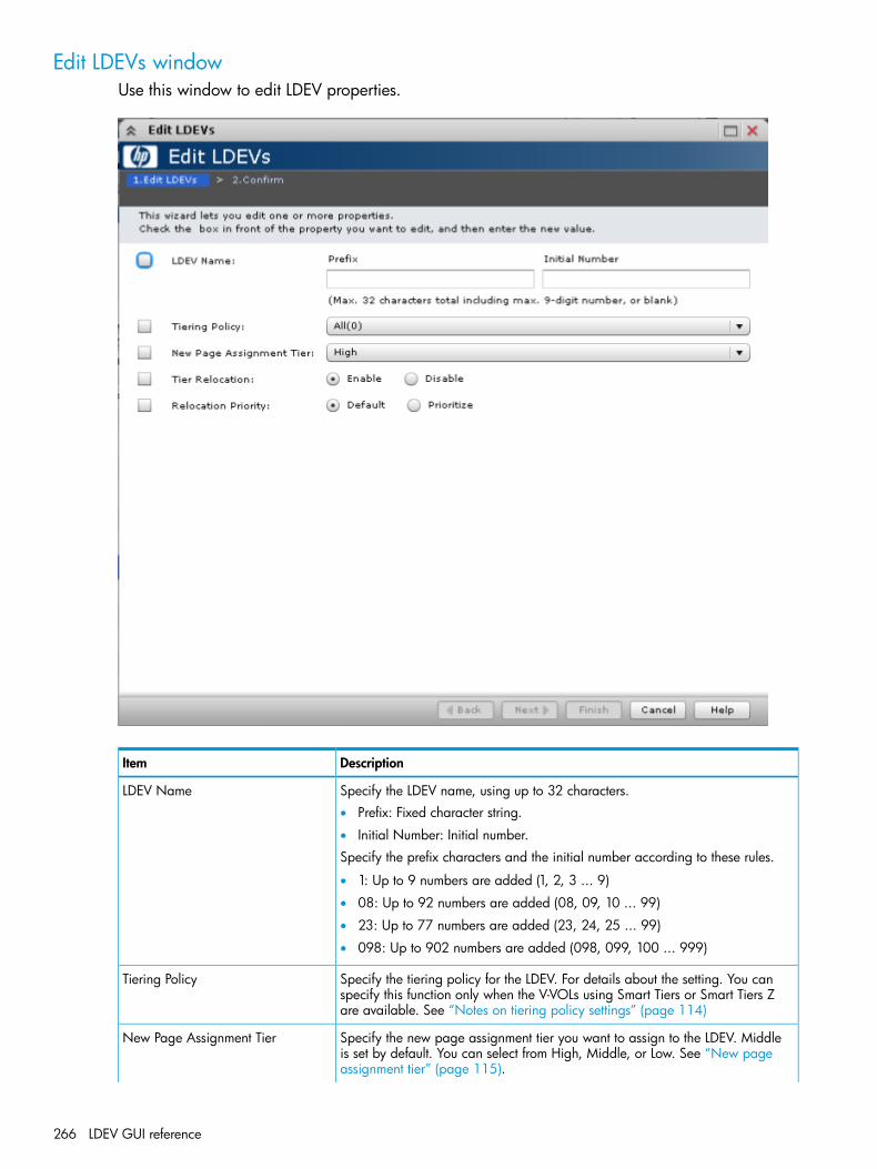
Edit LDEVs windowUse this window to edit LDEV properties.
DescriptionItem
Specify the LDEV name, using up to 32 characters.LDEV Name• Prefix: Fixed character string.
• Initial Number: Initial number.
Specify the prefix characters and the initial number according to these rules.
• 1: Up to 9 numbers are added (1, 2, 3 ... 9)
• 08: Up to 92 numbers are added (08, 09, 10 ... 99)
• 23: Up to 77 numbers are added (23, 24, 25 ... 99)
• 098: Up to 902 numbers are added (098, 099, 100 ... 999)
Specify the tiering policy for the LDEV. For details about the setting. You canspecify this function only when the V-VOLs using Smart Tiers or Smart Tiers Zare available. See “Notes on tiering policy settings” (page 114)
Tiering Policy
Specify the new page assignment tier you want to assign to the LDEV. Middleis set by default. You can select from High, Middle, or Low. See “New pageassignment tier” (page 115).
New Page Assignment Tier
266 LDEV GUI reference

DescriptionItem
You can specify this function only when the V-VOLs that use Smart Tiers or SmartTiers Z are available.
Specify Enable or Disable for the performing of the tier relocation. You canspecify this function only when the V-VOLs using Smart Tiers or Smart Tiers Zare available.
Tier Relocation
Specify the relocation priority assigned to the LDEV. You can set this functionunder the following conditions:
Relocation Priority
• When there are V-VOLs where Smart Tiers or Smart Tiers Z is enabled.
• When the tier relocation is enabled.
Edit LDEVs Confirm windowConfirm proposed settings, name the task, and then click Apply. The task will be added to theexecution queue.
DescriptionItem
The LDEV identifier, which is the combination of LDKC, CU, and LDEV.LDEV ID
The LDEV name, including the combination of prefix characters and theinitial number.
LDEV Name
The parity group identifier.Parity Group ID
The pool name and pool identifier.Pool Name (ID)
The emulation type.Emulation Type
The LDEV capacity.Capacity
Edit LDEVs wizard 267

DescriptionItem
The type of LDEV.Provisioning Type• Basic: Internal volume.
• THP: THP V-VOL.
• External: External volume.
• Snapshot: Fast Snap volume or Snapshot volume.
The tiering policy. A hyphen is displayed for volumes other than SmartTiers or Smart Tiers Z volumes.
Tiering Policy
Displays the new page assignment tier for the LDEV. A hyphen (-) isdisplayed for volumes other than Smart Tiers or Smart Tiers Z volumes.
New Page Assignment Tier
Displays whether tier relocation is enabled or disabled. A hyphen (-) isdisplayed for volumes other than Smart Tiers or Smart Tiers Z volumes.
Tier Relocation
Displays the relocation priority assigned to the LDEV. A hyphen is displayedif LDEV is the one of following:
Relocation Priority
• LDEV other than Smart Tiers.
• LDEV other than Smart Tiers Z.
• The tier relocation of LDEV is set to disabled.
Change LDEV Settings windowUse this window to edit one or more LDEV properties.
DescriptionItem
Specify the LDEV name, using up to 32 characters.LDEV NamePrefix: Fixed character string.Initial Number: Initial number.Specify the prefix character and the initial number according to these rules.
• 1: Up to 9 numbers are added (1, 2, 3 ... 9)
• 08: Up to 92 numbers are added (08, 09, 10 ... 99)
• 23: Up to 77 numbers are added (23, 24, 25 ... 99)
• 098: Up to 902 numbers are added (098, 099, 100 ... 999)
Specify the LDEV identifier, which is the combination of LDKC, CU, and LDEV.Assigns the ID at a certain interval starting with the ID you specify.
Initial LDEV ID
Specify the LDKC number. It is fixed to 00.LDKC
268 LDEV GUI reference

DescriptionItem
Specify the CU number.CU
Specify the LDEV number.DEV
Specify the interval of the assigned LDEV ID.Interval
Opens the View LDEV IDs window.View LDEV IDs
Select the processor blade you want to assign to the LDEV.Processor BladeSelect any ID or Auto.Select an ID from MPB0 to MPB7. If automatic assignment is enabled for one ormore processors, you can also select Auto.
View SSIDs windowUse this window to view storage system identifier information.
DescriptionItem
The LDKC number.LDKC
The control unit number.CU
The range of LDEVs that can be allocated to the SSID. Each LDEV group (dividedby LDEV boundary) has a unique SSID.
LDEV Boundary
The storage system identifier in hexadecimal format.SSID
Select Free Spaces windowUse this window to view information about available free space slots in the parity group. Only thefree spaces in the parity groups assigned to the logged-on user are available.
View SSIDs window 269

DescriptionItem
The parity group identifier.Parity Group ID
The sequence number for identifying free space in the parity group.Free Space No.
The RAID level. An asterisk "*" indicates that the parity group to which the LDEV belongs isinterleaved (concatenated).
RAID Level
The capacity of free space.Capacity
The emulation type of the parity group.Base Emulation Type
The drive type and rpm in use on this LDEV.Drive Type/ RPM
The protection status on the parity group.Protection• SATA W/V, SATA E, or Standard.
• SAS, SSD, and External appears as Standard.
Opens the View Physical Location window.View Physical Location
270 LDEV GUI reference
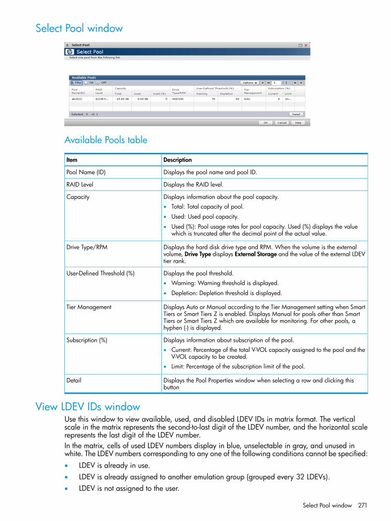
Select Pool window
Available Pools table
DescriptionItem
Displays the pool name and pool ID.Pool Name (ID)
Displays the RAID level.RAID Level
Displays information about the pool capacity.Capacity• Total: Total capacity of pool.
• Used: Used pool capacity.
• Used (%): Pool usage rates for pool capacity. Used (%) displays the valuewhich is truncated after the decimal point of the actual value.
Displays the hard disk drive type and RPM. When the volume is the externalvolume, Drive Type displays External Storage and the value of the external LDEVtier rank.
Drive Type/RPM
Displays the pool threshold.User-Defined Threshold (%)• Warning: Warning threshold is displayed.
• Depletion: Depletion threshold is displayed.
Displays Auto or Manual according to the Tier Management setting when SmartTiers or Smart Tiers Z is enabled. Displays Manual for pools other than Smart
Tier Management
Tiers or Smart Tiers Z which are available for monitoring. For other pools, ahyphen (-) is displayed.
Displays information about subscription of the pool.Subscription (%)• Current: Percentage of the total V-VOL capacity assigned to the pool and the
V-VOL capacity to be created.• Limit: Percentage of the subscription limit of the pool.
Displays the Pool Properties window when selecting a row and clicking thisbutton
Detail
View LDEV IDs windowUse this window to view available, used, and disabled LDEV IDs in matrix format. The verticalscale in the matrix represents the second-to-last digit of the LDEV number, and the horizontal scalerepresents the last digit of the LDEV number.In the matrix, cells of used LDEV numbers display in blue, unselectable in gray, and unused inwhite. The LDEV numbers corresponding to any one of the following conditions cannot be specified:• LDEV is already in use.• LDEV is already assigned to another emulation group (grouped every 32 LDEVs).• LDEV is not assigned to the user.
Select Pool window 271

DescriptionItem
The emulation type selected in the Create LDEVs window. See “Emulation groupsand types” (page 272) for a list.
Usage of selected emulation type
The LDEV identifier, which is the combination of LDKC, CU, and LDEV.LDEV IDs• LDKC: Indicates the LDKC number.
• CU: Indicates the CU number.
Emulation groups and typesThe following table shows the emulation groups and emulation types for mainframe systems.
D-type (Overseas PCM) emulation typeEmulation group
3390-3, 3390-A, 3390-3A, 3390-3B, 3390-3C, 3390-9, 3390-9A, 3390-9B,3390-9C, 3390-L, 3390-LA, 3390-LB, 3390-LC, 3390-M, 3390-MA, 3390-MB,3390-MC, 3390-V
Group 1
3390-3RGroup 2
3380-3, 3380-3A, 3380-3B, 3380-3CGroup 3
The following table shows the emulation groups and emulation types for open systems.
D-type (Overseas PCM) emulation typeEmulation group
OPEN-3, OPEN-8, OPEN-9, OPEN-EGroup 4
NoneGroup 5
OPEN-VGroup 6
272 LDEV GUI reference
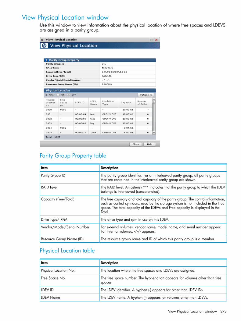
View Physical Location windowUse this window to view information about the physical location of where free spaces and LDEVSare assigned in a parity group.
Parity Group Property table
DescriptionItem
The parity group identifier. For an interleaved parity group, all parity groupsthat are contained in the interleaved parity group are shown.
Parity Group ID
The RAID level. An asterisk "*" indicates that the parity group to which the LDEVbelongs is interleaved (concatenated).
RAID Level
The free capacity and total capacity of the parity group. The control information,such as control cylinders, used by the storage system is not included in the Free
Capacity (Free/Total)
space. The total capacity of the LDEVs and Free capacity is displayed in theTotal.
The drive type and rpm in use on this LDEV.Drive Type/ RPM
For external volumes, vendor name, model name, and serial number appear.For internal volumes, -/-/- appears.
Vendor/Model/Serial Number
The resource group name and ID of which this parity group is a member.Resource Group Name (ID)
Physical Location table
DescriptionItem
The location where the free spaces and LDEVs are assigned.Physical Location No.
The free space number. The hyphenation appears for volumes other than freespaces.
Free Space No.
The LDEV identifier. A hyphen (-) appears for other than LDEV IDs.LDEV ID
The LDEV name. A hyphen (-) appears for volumes other than LDEVs.LDEV Name
View Physical Location window 273

DescriptionItem
The emulation type. A hyphen (-) appears for volumes other than LDEVs.Emulation Type
The capacity of the LDEV.Capacity
The number of paths set for the LDEV. A hyphen (-) appears for volumes otherthan LDEVs.
Number of Paths
Edit SSIDs windowUse this window to select a storage system identifier whose properties can be changed.
DescriptionItem
The LDKC number.LDKC
The control unit number.CU
The range of LDEVs that can be allocated to the SSID. Each LDEV group (dividedby LDEV boundary) has a unique SSID.
LDEV Boundary
The storage system identifier in hexadecimal format.SSID
Indicates whether the storage system identifier is can be changed.SSID Changeable• Yes: The SSID can be changed. The SSID was assigned when creating LDEVs
but has not yet been registered (unused).• No: The SSID can not be changed. The SSID has been registered (used) and
cannot be changed.• Hyphen (-): The SSID is not assigned.
Select a row and click this button to open the Change SSID window.Change SSIDs
Change SSIDs windowUse this window to change the SSID.
274 LDEV GUI reference

DescriptionItem
Specify the initial storage system identifier in hexadecimal format. The defaultis 0004 if none is specified.
Initial SSID
Format LDEVs wizardUse this window to format LDEVs. LDEVs must be formatted before you can use the storage space.
Format LDEVs window
DescriptionItem
Select the type of formatting to be used on this LDEV.Format Type• Quick Format (default): Select this to perform quick-formatting. This option is
available only for formatting an internal volume.• Write-to-Control Blocks: Select this when the provisioning type is for a
mainframe external volume. The management area of external volumes formainframe systems will be overwritten. This is the default option for an externalvolume.
• Normal Format: Select this to perform normal-formatting. This option isavailable for formatting an internal volume, or an external volume whoseemulation type is OPEN.
The number of selected parity groups.Number of Selected Parity Groups
Format LDEVs Confirm windowConfirm proposed settings, name the task, and then click Apply. The task will be added to theexecution queue.
Format LDEVs wizard 275

DescriptionItem
The LDEV identifier, which is the combination of LDKC, CU, and LDEV.LDEV ID
The LDEV name.LDEV Name
The parity group identifier.Parity Group ID
The pool name and pool identifier.Pool Name (ID)
The emulation type.Emulation Type
The LDEV capacity.Capacity
The provisioning type to be assigned to the LDEV.Provisioning Type• Basic: Internal volume.
• THP: THP V-VOL.
• External: External volume.
• Snapshot: Fast Snap volume or Snapshot volume.
Displays the attribute of the LDEV.Attribute• Command Device: Command device.
• System Disk: System disk
• TSE: TSE-VOL.
• Hyphen (-): Volume in which the attribute is not defined.
How the LDEV will be formatted.Format Type• Quick Format: Quick-formatting is performed.
• Normal Format: Normal formatting is performed.
• Write-to-Control Blocks: The management area of external volumes formainframe systems is overwritten.
Restore LDEVs windowUse this window to recover blocked LDEVs.
276 LDEV GUI reference
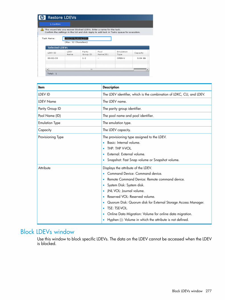
DescriptionItem
The LDEV identifier, which is the combination of LDKC, CU, and LDEV.LDEV ID
The LDEV name.LDEV Name
The parity group identifier.Parity Group ID
The pool name and pool identifier.Pool Name (ID)
The emulation type.Emulation Type
The LDEV capacity.Capacity
The provisioning type assigned to the LDEV.Provisioning Type• Basic: Internal volume.
• THP: THP V-VOL.
• External: External volume.
• Snapshot: Fast Snap volume or Snapshot volume.
Displays the attribute of the LDEV.Attribute• Command Device: Command device.
• Remote Command Device: Remote command device.
• System Disk: System disk.
• JNL VOL: Journal volume.
• Reserved VOL: Reserved volume.
• Quorum Disk: Quorum disk for External Storage Access Manager.
• TSE: TSE-VOL.
• Online Data Migration: Volume for online data migration.
• Hyphen (-): Volume in which the attribute is not defined.
Block LDEVs windowUse this window to block specific LDEVs. The data on the LDEV cannot be accessed when the LDEVis blocked.
Block LDEVs window 277
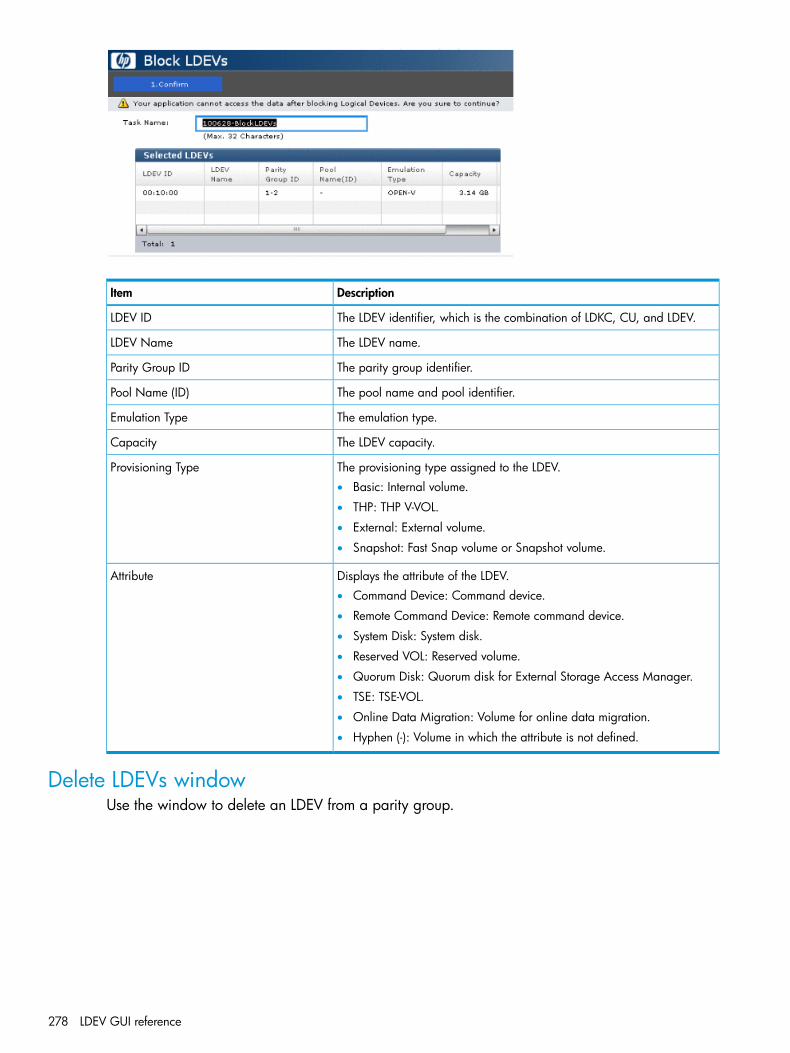
DescriptionItem
The LDEV identifier, which is the combination of LDKC, CU, and LDEV.LDEV ID
The LDEV name.LDEV Name
The parity group identifier.Parity Group ID
The pool name and pool identifier.Pool Name (ID)
The emulation type.Emulation Type
The LDEV capacity.Capacity
The provisioning type assigned to the LDEV.Provisioning Type• Basic: Internal volume.
• THP: THP V-VOL.
• External: External volume.
• Snapshot: Fast Snap volume or Snapshot volume.
Displays the attribute of the LDEV.Attribute• Command Device: Command device.
• Remote Command Device: Remote command device.
• System Disk: System disk.
• Reserved VOL: Reserved volume.
• Quorum Disk: Quorum disk for External Storage Access Manager.
• TSE: TSE-VOL.
• Online Data Migration: Volume for online data migration.
• Hyphen (-): Volume in which the attribute is not defined.
Delete LDEVs windowUse the window to delete an LDEV from a parity group.
278 LDEV GUI reference

DescriptionItem
The LDEV identifier, which is the combination of LDKC, CU, and LDEV.LDEV ID
The LDEV name.LDEV Name
The parity group identifier.Parity Group ID
The pool name and pool identifier.Pool Name (ID)
The emulation type.Emulation Type
The LDEV capacity.Capacity
The provisioning type assigned to the LDEV.Provisioning Type• Basic: Internal volume.
• THP: THP V-VOL.
• External: External volume.
• Snapshot: Fast Snap volume or Snapshot volume.
Displays the attribute of the LDEV.Attribute• Command Device: Command device.
• System Disk: System disk.
• TSE: TSE-VOL.
• Hyphen (-): Volume in which the attribute is not defined.
LDEV Properties windowUse this window to view properties assigned to a selected LDEV.• “LDEV Properties table”• “Basic tab”• “Local Replication Tab”
LDEV Properties window 279

LDEV Properties table
DescriptionItem
The LDEV identifier, which is the combination of LDKC, CU, and LDEV.LDEV ID
Displays the LDEV name.LDEV Name
Displays the emulation type.Emulation Type
Displays the LDEV capacity.CapacityIf the component of the LUSE volume is selected, a hyphen (-) is displayed.If the top LDEV of the LUSE volume is selected, total capacity of the LUSEvolume including components is displayed.
Basic tabLDEV basic information is displayed in the Basic Properties, LUNs, Hosts, and ConcatenatedLDEVs(LUSE) tables.
280 LDEV GUI reference
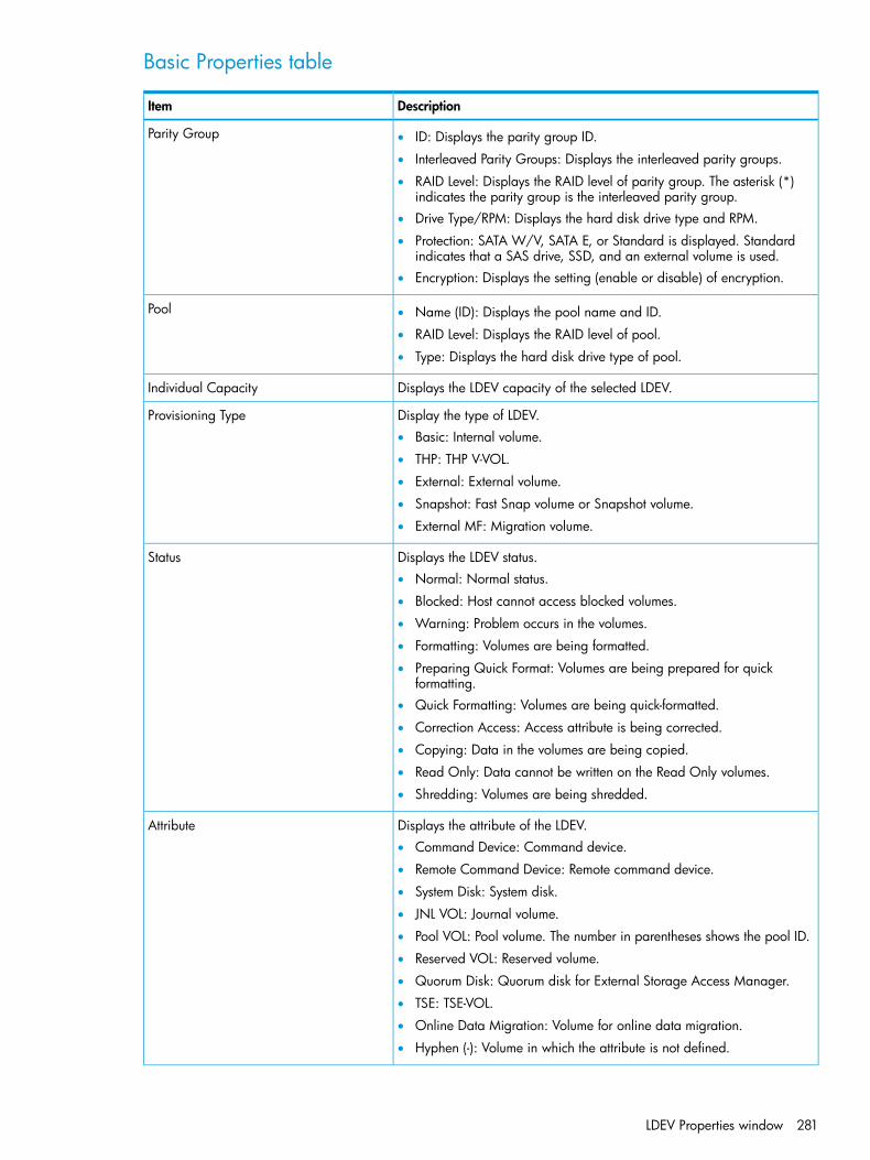
Basic Properties table
DescriptionItem
Parity Group • ID: Displays the parity group ID.
• Interleaved Parity Groups: Displays the interleaved parity groups.
• RAID Level: Displays the RAID level of parity group. The asterisk (*)indicates the parity group is the interleaved parity group.
• Drive Type/RPM: Displays the hard disk drive type and RPM.
• Protection: SATA W/V, SATA E, or Standard is displayed. Standardindicates that a SAS drive, SSD, and an external volume is used.
• Encryption: Displays the setting (enable or disable) of encryption.
Pool • Name (ID): Displays the pool name and ID.
• RAID Level: Displays the RAID level of pool.
• Type: Displays the hard disk drive type of pool.
Displays the LDEV capacity of the selected LDEV.Individual Capacity
Display the type of LDEV.Provisioning Type• Basic: Internal volume.
• THP: THP V-VOL.
• External: External volume.
• Snapshot: Fast Snap volume or Snapshot volume.
• External MF: Migration volume.
Displays the LDEV status.Status• Normal: Normal status.
• Blocked: Host cannot access blocked volumes.
• Warning: Problem occurs in the volumes.
• Formatting: Volumes are being formatted.
• Preparing Quick Format: Volumes are being prepared for quickformatting.
• Quick Formatting: Volumes are being quick-formatted.
• Correction Access: Access attribute is being corrected.
• Copying: Data in the volumes are being copied.
• Read Only: Data cannot be written on the Read Only volumes.
• Shredding: Volumes are being shredded.
Displays the attribute of the LDEV.Attribute• Command Device: Command device.
• Remote Command Device: Remote command device.
• System Disk: System disk.
• JNL VOL: Journal volume.
• Pool VOL: Pool volume. The number in parentheses shows the pool ID.
• Reserved VOL: Reserved volume.
• Quorum Disk: Quorum disk for External Storage Access Manager.
• TSE: TSE-VOL.
• Online Data Migration: Volume for online data migration.
• Hyphen (-): Volume in which the attribute is not defined.
LDEV Properties window 281
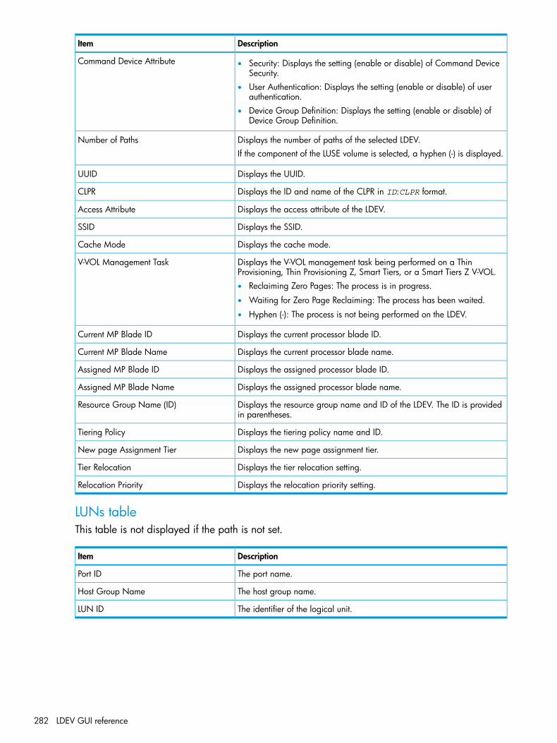
DescriptionItem
Command Device Attribute • Security: Displays the setting (enable or disable) of Command DeviceSecurity.
• User Authentication: Displays the setting (enable or disable) of userauthentication.
• Device Group Definition: Displays the setting (enable or disable) ofDevice Group Definition.
Displays the number of paths of the selected LDEV.Number of PathsIf the component of the LUSE volume is selected, a hyphen (-) is displayed.
Displays the UUID.UUID
Displays the ID and name of the CLPR in ID:CLPR format.CLPR
Displays the access attribute of the LDEV.Access Attribute
Displays the SSID.SSID
Displays the cache mode.Cache Mode
Displays the V-VOL management task being performed on a ThinProvisioning, Thin Provisioning Z, Smart Tiers, or a Smart Tiers Z V-VOL.
V-VOL Management Task
• Reclaiming Zero Pages: The process is in progress.
• Waiting for Zero Page Reclaiming: The process has been waited.
• Hyphen (-): The process is not being performed on the LDEV.
Displays the current processor blade ID.Current MP Blade ID
Displays the current processor blade name.Current MP Blade Name
Displays the assigned processor blade ID.Assigned MP Blade ID
Displays the assigned processor blade name.Assigned MP Blade Name
Displays the resource group name and ID of the LDEV. The ID is providedin parentheses.
Resource Group Name (ID)
Displays the tiering policy name and ID.Tiering Policy
Displays the new page assignment tier.New page Assignment Tier
Displays the tier relocation setting.Tier Relocation
Displays the relocation priority setting.Relocation Priority
LUNs tableThis table is not displayed if the path is not set.
DescriptionItem
The port name.Port ID
The host group name.Host Group Name
The identifier of the logical unit.LUN ID
282 LDEV GUI reference

Hosts tableThis table provides information about the host that can view LDEVs. This table is not available ifthe WWN is not registered in the host to which the path is set.
DescriptionItem
The WWN of the host that can view LDEVs.HBA WWN
The host name.Host Name
Concatenated LDEVs (LUSE) tableIf the volume is the top LDEV or the component in the LUSE volume, the information about the LDEVis not displayed.
DescriptionItem
Displays the LDEV ID.LDEV ID
Displays the LDEV name.LDEV Name
Displays the parity group ID.Parity Group ID
Displays the emulation type.Emulation Type
Displays the capacity of the LDEV.Individual Capacity
Displays the attribute of the LDEV in the LUSE volume. The Top is displayedif the LDEV locates in the top of the LUSE volume. The Member is displayedif the LDEV locates in the LUSE volume other than the top.
LUSE Attribute
Local Replication TabInformation about the volume of the local replication pair is displayed in the Replication Properties,and Pairs tables.For details about each item, see the HP XP P9000 Business Copy User Guide, HP XP P9000Business Copy for Mainframe Systems User Guide, HP XP P9000 Fast Snap User Guide, HP XPP9000 Snapshot User Guide, or HP XP P9000 for Compatible FlashCopy Mirroring User Guide.
Replication Properties table
DescriptionItem
Displays the status of the Business Copy L1 pair.Business Copy L1
Displays the status of the Business Copy L2 pair.Business Copy L2
Displays the status of the Snapshot pair.Snapshot
Displays the status of the Fast Snap pair.Fast Snap
Displays the status of the Business Copy Z pair.Business Copy for Mainframe
Displays the status of the Compatible FlashCopy relationship.Compatible FlashCopy
Displays the status of the Compatible FlashCopy SE relationship.Compatible FlashCopy SE
If the volume is the reserved volume for the pair, Yes is displayed. If thevolume other than the reserved volume is specified, No is displayed.
Reserve Volume
LDEV Properties window 283

Pairs table
DescriptionItem
Displays LDEV ID, LDEV Name, Emulation type, Capacity, CLPR ID, andCLPR name of the primary volume.
Primary Volume
Displays the copy type of the pair.Copy Type
Displays the snapshot group nameSnapshot group
Displays the pair status.Status
Displays LDEV ID, LDEV Name, Emulation type, Capacity, CLPR ID, andCLPR name of the secondary volume.
Secondary Volume
Displays the date when the Snapshot data of the pair was stored.Snapshot Date
Displays the pool name(ID) of the pair.Pool Name(ID)
Displays the pace of copying of the pair.Copy Pace
Displays the consistency group number of the pair.CTG ID
Displays the mirror unit number of the pair.Mirror Unit
Displays the View Pair Properties.Detail
Top window when selecting ComponentsUse this window to view information about the controller chassis components in the storage system.
284 LDEV GUI reference

• “Summary”• “Components tab”
Summary
DescriptionItem
The number of controller chassis.Number of Controller Chassis
Components tab
DescriptionItem
The chassis identifier of the storage system.Chassis ID
The chassis type.Chassis Type
Opens a window where you can export configuration information listed in thetable to a file that can be used for multiple purposes, such as backup or reporting.
Export
Top window when selecting controller chassis under ComponentsUse this window to view information about MP processor blades in the storage system.
Top window when selecting controller chassis under Components 285
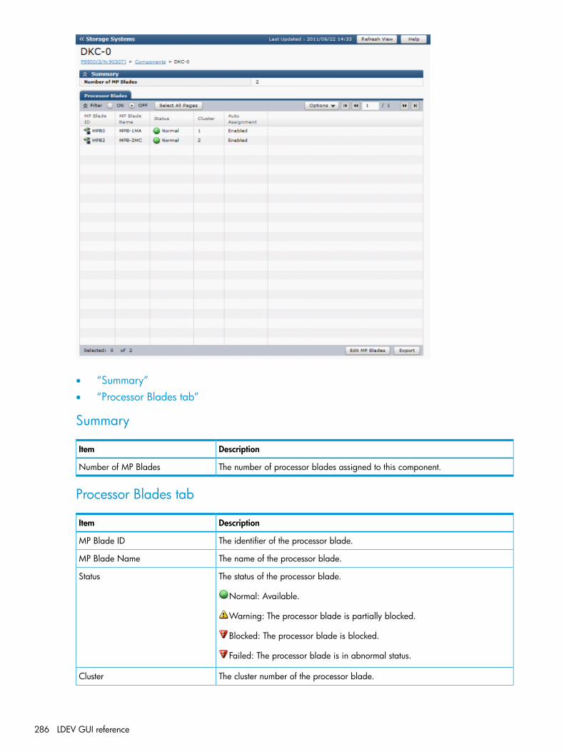
• “Summary”• “Processor Blades tab”
Summary
DescriptionItem
The number of processor blades assigned to this component.Number of MP Blades
Processor Blades tab
DescriptionItem
The identifier of the processor blade.MP Blade ID
The name of the processor blade.MP Blade Name
The status of the processor blade.Status
Normal: Available.
Warning: The processor blade is partially blocked.
Blocked: The processor blade is blocked.
Failed: The processor blade is in abnormal status.
The cluster number of the processor blade.Cluster
286 LDEV GUI reference
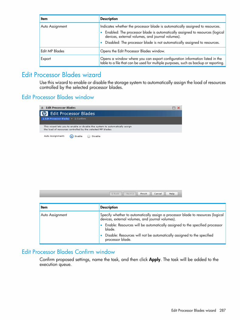
DescriptionItem
Indicates whether the processor blade is automatically assigned to resources.Auto Assignment• Enabled: The processor blade is automatically assigned to resources (logical
devices, external volumes, and journal volumes).• Disabled: The processor blade is not automatically assigned to resources.
Opens the Edit Processor Blades window.Edit MP Blades
Opens a window where you can export configuration information listed in thetable to a file that can be used for multiple purposes, such as backup or reporting.
Export
Edit Processor Blades wizardUse this wizard to enable or disable the storage system to automatically assign the load of resourcescontrolled by the selected processor blades.
Edit Processor Blades window
DescriptionItem
Specify whether to automatically assign a processor blade to resources (logicaldevices, external volumes, and journal volumes).
Auto Assignment
• Enable: Resources will be automatically assigned to the specified processorblade.
• Disable: Resources will not be automatically assigned to the specifiedprocessor blade.
Edit Processor Blades Confirm windowConfirm proposed settings, name the task, and then click Apply. The task will be added to theexecution queue.
Edit Processor Blades wizard 287

DescriptionItem
The processor blade identifier.MP Blade ID
The cluster number of the processor blade.Cluster
Indicates whether automatic assignment of processor blades is in use.Auto Assignment• Enabled: A processor blade is automatically assigned to resources
(logical devices, external volumes, and journal volumes).• Disabled: A processor blade is not automatically assigned to resources.
Assign Processor Blade wizardUse this wizard to assign a processor blade that will control selected resources.
Assign Processor Blade windowUse this window to select a processor blade to assign to an LDEV.
DescriptionItem
Change the processor blade assigned to the LDEV.Processor Bladeprocessor blade ID: The selected processor blade is assigned to the LDEV.
Assign Processor Blade Confirm windowConfirm proposed settings, name the task, and then click Apply. The task will be added to theexecution queue.
288 LDEV GUI reference
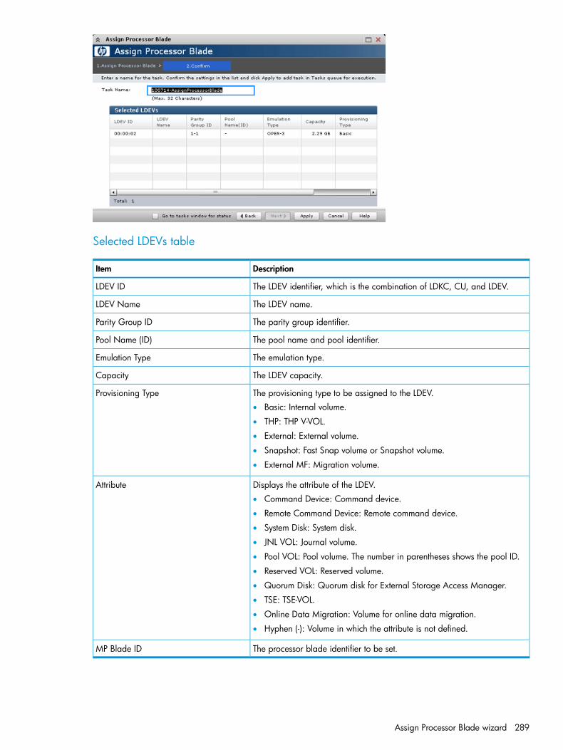
Selected LDEVs table
DescriptionItem
The LDEV identifier, which is the combination of LDKC, CU, and LDEV.LDEV ID
The LDEV name.LDEV Name
The parity group identifier.Parity Group ID
The pool name and pool identifier.Pool Name (ID)
The emulation type.Emulation Type
The LDEV capacity.Capacity
The provisioning type to be assigned to the LDEV.Provisioning Type• Basic: Internal volume.
• THP: THP V-VOL.
• External: External volume.
• Snapshot: Fast Snap volume or Snapshot volume.
• External MF: Migration volume.
Displays the attribute of the LDEV.Attribute• Command Device: Command device.
• Remote Command Device: Remote command device.
• System Disk: System disk.
• JNL VOL: Journal volume.
• Pool VOL: Pool volume. The number in parentheses shows the pool ID.
• Reserved VOL: Reserved volume.
• Quorum Disk: Quorum disk for External Storage Access Manager.
• TSE: TSE-VOL.
• Online Data Migration: Volume for online data migration.
• Hyphen (-): Volume in which the attribute is not defined.
The processor blade identifier to be set.MP Blade ID
Assign Processor Blade wizard 289

View Management Resource Usage window
Management Resource Usage table
DescriptionItem
The current number and maximum allowed number of cache managementdevices in the storage system are displayed.
Number of Cache Management Devices
290 LDEV GUI reference
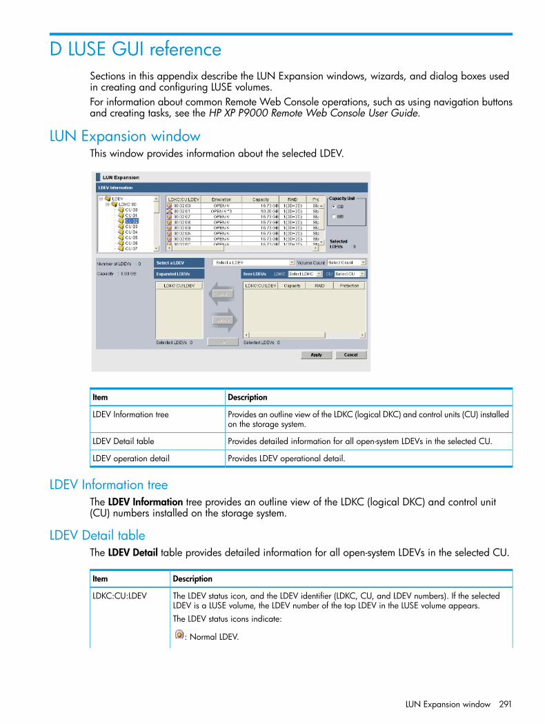
D LUSE GUI referenceSections in this appendix describe the LUN Expansion windows, wizards, and dialog boxes usedin creating and configuring LUSE volumes.For information about common Remote Web Console operations, such as using navigation buttonsand creating tasks, see the HP XP P9000 Remote Web Console User Guide.
LUN Expansion windowThis window provides information about the selected LDEV.
DescriptionItem
Provides an outline view of the LDKC (logical DKC) and control units (CU) installedon the storage system.
LDEV Information tree
Provides detailed information for all open-system LDEVs in the selected CU.LDEV Detail table
Provides LDEV operational detail.LDEV operation detail
LDEV Information treeThe LDEV Information tree provides an outline view of the LDKC (logical DKC) and control unit(CU) numbers installed on the storage system.
LDEV Detail tableThe LDEV Detail table provides detailed information for all open-system LDEVs in the selected CU.
DescriptionItem
The LDEV status icon, and the LDEV identifier (LDKC, CU, and LDEV numbers). If the selectedLDEV is a LUSE volume, the LDEV number of the top LDEV in the LUSE volume appears.
LDKC:CU:LDEV
The LDEV status icons indicate:
: Normal LDEV.
LUN Expansion window 291

DescriptionItem
: Expanded (LUSE) volume
• An LDEV number ending with # (for example, 00:00:01#) indicates that the LDEV is anexternal volume. For details regarding external volumes, see the HP XP P9000 ExternalStorage for Open and Mainframe Systems User Guide.
• An LDEV number ending with V (for example, 00:00:01V) indicates that the LDEV is a virtualvolume (V-VOL) for Fast Snap or Snapshot. For details regarding V-VOLs, see the HP XPP9000 Fast Snap User Guide or the HP XP P9000 Snapshot User Guide.
The emulation type. If the selected LDEV is a LUSE volume, the emulation type appears with anasterisk and the number of volumes in the LUSE volume (for example, OPEN-E*5).
Emulation
The LDEV capacity, in either MB or GB, depending on which unit is selected in the CapacityUnit box.
Capacity
The RAID level of the LDEV. A hyphen (-) indicates the RAID level is unspecified when the LDEVis an external LU or a virtual volume (V-VOL).
RAID
The data protection level.Protection• SATA-W/V: Indicates the data protection level if the write and verify mode is set on a SATA
drive.• SATA-E: Indicates the data protection level if the Enhanced mode is set on a SATA drive.
• Standard: Indicates that a SAS drive, SSD, external volume, or virtual volume (V-VOL) isbeing used.
The parity group. If the LDEV extends over two or more parity groups, the PG column shows thesmaller parity group number.
PG
• A parity group number starting with E (for example, E1-1) indicates that the parity groupconsists of one or more external LUs.
• A parity group number starting with V (for example, V1-1) indicates that the parity groupconsists of one or more virtual volumes (V-VOLs) for Fast Snap or Snapshot.
The number of paths set for the LDEV. If this column shows the number of paths for an LDEV,you can use the LDEV as the top LDEV of a LUSE volume.
Paths
The access attribute that is set for the LDEV.Access Attribute• Read/Write: Both read and write operations are permitted on the logical volume.
• Read-only: Read operations are permitted on the logical volume.
• Protect: Neither read nor write operations are permitted.
The local storage system cache mode.Cache mode• Disable: Indicates the local storage system cache memory is set to be unused for responding
to the I/O request for the external volume from the host.• Enable: Indicates the local storage system cache memory is set to be used for responding to
the I/O request for the external volume from the host.
The drive types of external volumes.Ext. VOL Info• Asterisk (*): Indicates a SATA or BD drive containing external volumes.
• Dollar sign ($): Indicates an SSD containing external volumes.
• Hyphen (-): Indicates a drive containing internal volumes.
• Nothing appears for SAS drives containing external volumes.
The drive types of internal volumes.Int. VOL Info• Asterisk (*): Indicates a SATA drive containing internal volumes.
• Dollar sign ($): Indicates an SSD containing internal volumes.
• Hyphen (-): Indicates a drive containing external volumes.
• Nothing appears for a SAS drive containing internal volumes.
292 LUSE GUI reference

DescriptionItem
The resource group name and identifier of the LDEV.Resource GroupName (ID)
The two-digit identifier of the cache logical partition to which the selected volumes belong.CLPRFor detailed information about CLPRs, see the HP XP P9000 Cache Partition User Guide.
The number of a pool associated with virtual volumes (V-VOLs) for Thin Provisioning.Pool ID• Hyphen (-): Indicates a virtual volume (V-VOL) for Thin Provisioning is not associated with a
pool.• Nothing appears for volumes that are not virtual volumes (V-VOLs) for Thin Provisioning.
Click an option to select the capacity, in either GB (default) or MB, of the LDEV selected in theCapacity column.
Capacity Unit
The number of LDEVs that are selected in the LDEV Detail table.Selected LDEVs
LDEV operation detailThe remainder of the LUN Expansion window provides LDEV operational detail.
DescriptionItem
The LDEVs and LUSE volumes of the selected CU that are eligible to become part of a LUSEvolume appear in this list. The selected LDEV number becomes the top LDEV number of a LUSEvolume.
Select an LDEV
The number of LDEVs that form a LUSE volume.Volume CountFor example, if you select 3 in the Volume Count box, three LDEVs are expected to form a LUSEvolume and then three LDEVs are added to the Expanded LDEVs list.You can select an LDEV only from the Volume Count box. You cannot select a LUSE volume.
A list of the LDEVs that are selected as LUSE volume components. An LDEV is added to this listby clicking Add.
Expanded LDEVs
• Selected LDEVs: Number of LDEVs selected in the Expanded LDEVs list.
• Number of LDEVs: Total number of LDEVs selected in the Expanded LDEVs list.
• Size: Total capacity, in either GB or MB, of the LDEVs selected in the Expanded LDEVs list.
The LDEVs or LUSE volumes selected in the Select an LDEV box that are eligible to become partof a LUSE volume appear in this list.
Free LDEVs table
Use the lists on the upper right of the Free LDEVs table to narrow entries in this table. If youselect an LDKC and a CU from the LDKC and CU lists, the Free LDEVs table shows only theLDEVs belonging to the selected LDKC and CU.
Moves a selected LDEV from the Free LDEVs list to the Expanded LDEVs list.Add
Moves a selected LDEV from the Expanded LDEVs list to the Free LDEVs list.Delete
Creates a LUSE volume consisting of the volumes currently in the Expanded LDEVs list. The newLUSE appears in blue bold italics on the LUN Expansion window in the LDEV Detail table, butis not actually created until you click Apply.
Set
Applies the settings to the storage system.Apply
Cancels the settings.Cancel
LDEV operation detail 293

Free LDEVs table contains the following items
DescriptionItem
The LDEV status icon, and the LDEV identifier (LDKC, CU, and LDEV numbers). If the selectedLDEV is a LUSE volume, the LDEV number of the top LDEV in the LUSE volume appears.
LDKC:CU:LDEV
The LDEV status icons indicate:
: Normal LDEV.
: Expanded (LUSE) volume
• An LDEV number ending with # (for example, 00:00:01#) indicates that the LDEV is anexternal volume. For details regarding external volumes, see the HP XP P9000 ExternalStorage for Open and Mainframe Systems User Guide.
• An LDEV number ending with V (for example, 00:00:01V) indicates that the LDEV is a virtualvolume (V-VOL) for Fast Snap or Snapshot. For details regarding V-VOLs, see the HP XPP9000 Fast Snap User Guide or the HP XP P9000 Snapshot User Guide.
The capacity of the LDEV.Capacity
The RAID level of the LDEV. The RAID level is left unspecified with a hyphen (-) when the LDEVis an external LU or virtual volume (V-VOL).
RAID
The data protection level on the LDEV.Protection• SATA-W/V: Indicates the data protection level if the write and verify mode is set on a SATA
drive.• SATA-E: Indicates the data protection level if the Enhanced mode is set on a SATA drive.
• Standard: Indicates that a SAS drive, SSD, external volume, or virtual volume (V-VOL) isbeing used.
The parity group. If the LDEV extends over two or more parity groups, the PG column shows thesmaller parity group number.
PG
• A parity group number starting with E (for example, E1-1) indicates that the parity groupconsists of one or more external LUs.
• A parity group number starting with V (for example, V1-1) indicates that the parity groupconsists of one or more Fast Snap or Snapshot virtual volumes (V-VOLs).
The cache logical partition number. For detailed information about CLPRs, see the HP XP P9000Cache Partition User Guide.
CLPR
The number of LDEVs selected in the Free LDEVs table.Selected LDEVs
RAID Concatenation dialog boxUse this dialog box to view concatenated parity groups.
294 LUSE GUI reference
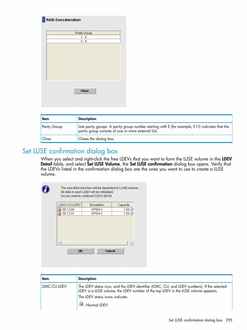
DescriptionItem
Lists parity groups. A parity group number starting with E (for example, E1-1) indicates that theparity group consists of one or more external LUs.
Parity Group
Closes the dialog box.Close
Set LUSE confirmation dialog boxWhen you select and right-click the free LDEVs that you want to form the LUSE volume in the LDEVDetail table, and select Set LUSE Volume, the Set LUSE confirmation dialog box opens. Verify thatthe LDEVs listed in the confirmation dialog box are the ones you want to use to create a LUSEvolume.
DescriptionItem
The LDEV status icon, and the LDEV identifier (LDKC, CU, and LDEV numbers). If the selectedLDEV is a LUSE volume, the LDEV number of the top LDEV in the LUSE volume appears.
LDKC:CU:LDEV
The LDEV status icons indicate:
: Normal LDEV.
Set LUSE confirmation dialog box 295

DescriptionItem
: Expanded (LUSE) volume
• An LDEV number ending with # (for example, 00:00:01#) indicates that the LDEV is anexternal volume. For details regarding external volumes, see the HP XP P9000 ExternalStorage for Open and Mainframe Systems User Guide.
• An LDEV number ending with V (for example, 00:00:01V) indicates that the LDEV is a virtualvolume (V-VOL) for Fast Snap or Snapshot. For details regarding V-VOLs, see the HP XPP9000 Fast Snap User Guide or the HP XP P9000 Snapshot User Guide.
The emulation type of the LDEV.Emulation
The capacity of the LDEV.Capacity
Creates the LUSE volume. Click this button to set the LUSE volume configuration having the LDEVsin the LUSE component list. The LDEVs registered as components of the LUSE volume appear inblue bold italics in the LDEV information list.
OK
Cancels the operation to create a LUSE volume using the LDEVs in the list.Cancel
Reset LUSE confirmation dialog boxUse this dialog box to confirm the selected LUSE volumes before resetting them. The list in thisdialog box shows the LDEVs created into a LUSE volume but not yet registered to the storage system.Click OK to reset the LUSE volume or click Cancel to reset to the state before they were created.
DescriptionItem
The LDEV status icon, and the LDEV identifier (LDKC, CU, and LDEV numbers). If the selectedLDEV is a LUSE volume, the LDEV number of the top LDEV in the LUSE volume appears.
LDKC:CU:LDEV
The LDEV status icons indicate:
: Normal LDEV.
: Expanded (LUSE) volumeAn LDEV number ending with # (for example, 00:00:01#) indicates that the LDEV is an externalvolume. For details regarding external volumes, see the HP XP P9000 External Storage for Openand Mainframe Systems User Guide.An LDEV number ending with V (for example, 00:00:01V) indicates that the LDEV is a virtualvolume (V-VOL) for Fast Snap or Snapshot. For details regarding V-VOLs, see the HP XP P9000Fast Snap User Guide or the HP XP P9000 Snapshot User Guide.
The emulation type of the LDEV.Emulation
296 LUSE GUI reference

DescriptionItem
The capacity of the LDEV.Capacity
Creates the LUSE volume. Click this button to create the LUSE volume configuration having theLDEVs in the LUSE component list. The LDEVs registered as components of the LUSE volumeappear in blue bold italics in the LDEV information list.
OK
Cancels the operation to create a LUSE volume using the LDEVs in the list.Cancel
Release LUSE confirmation dialog boxThis dialog box lists the LDEVs that contain LUSE volumes to be released. If the selected LUSEvolume has a path or if any other than a LUSE volume is selected, this dialog box lists only LDEVscontaining a LUSE volume to be released. For more information about error messages and actionson error, see the HP XP P9000 Remote Web Console Messages.
DescriptionItem
The LDEV status icon, and the LDEV identifier (LDKC, CU, and LDEV numbers). If the selectedLDEV is a LUSE volume, the LDEV number of the top LDEV in the LUSE volume appears.
LDKC:CU:LDEV
The LDEV status icons indicate:
: Normal LDEV.
: Expanded (LUSE) volume
• An LDEV number ending with # (for example, 00:00:01#) indicates that the LDEV is anexternal volume. For details regarding external volumes, see the HP XP P9000 ExternalStorage for Open and Mainframe Systems User Guide.
• An LDEV number ending with V (for example, 00:00:01V) indicates that the LDEV is a virtualvolume (V-VOL) for Fast Snap or Snapshot. For details regarding V-VOLs, see the HP XPP9000 Fast Snap User Guide or the HP XP P9000 Snapshot User Guide.
The emulation type of the LDEV.Emulation
The capacity of the LDEV.Capacity
Creates the LUSE volume. Click this button to set the LUSE volume configuration having the LDEVsin the LUSE component list. The LDEVs registered as components of the LUSE volume appear inblue bold italics in the LDEV information list.
OK
Cancels the operation to create a LUSE volume using the LDEVs in the list.Cancel
Release LUSE confirmation dialog box 297

LUSE Detail dialog boxThis dialog box provides information about the volumes (LDEVs) that are combined into a selectedLUSE volume.
DescriptionItem
The LDEV status icon, and the LDEV identifier (LDKC, CU, and LDEV numbers). If the selectedLDEV is a LUSE volume, the LDEV number of the top LDEV in the LUSE volume appears.
LDKC:CU:LDEV
The LDEV status icons indicate:
: Normal LDEV.
: Expanded (LUSE) volume
• An LDEV number ending with # (for example, 00:00:01#) indicates that the LDEV is anexternal volume. For details regarding external volumes, see the HP XP P9000 ExternalStorage for Open and Mainframe Systems User Guide.
• An LDEV number ending with V (for example, 00:00:01V) indicates that the LDEV is a virtualvolume (V-VOL) for Fast Snap or Snapshot. For details regarding V-VOLs, see the HP XPP9000 Fast Snap User Guide or the HP XP P9000 Snapshot User Guide.
The capacity of the LDEV.Capacity
The RAID level of the LDEV. A hyphen (-) indicates the RAID level is unspecified when the LDEVis an external LU or a virtual volume (V-VOL).
RAID
The data protection level on the LDEV.Protection• SATA-W/V: Indicates the data protection level if the write and verify mode is set on a SATA
drive.• SATA-E: Indicates the data protection level if the Enhanced mode is set on a SATA drive.
• Standard: Indicates that a SAS drive, SSD, external volume, or virtual volume (V-VOL) isbeing used.
The number of the parity group.PG• A parity group number starting with E (for example, E1-1) indicates that the parity group
consists of one or more external LUs.• A parity group number starting with V (for example, V1-1) indicates that the parity group
consists of one or more Fast Snap or Snapshot virtual volumes (V-VOLs).
The cache logical partition number.CLPRFor detailed information about CLPRs, see the HP XP P9000 Cache Partition User Guide.
Closes the LUSE Detail dialog box.Close
298 LUSE GUI reference
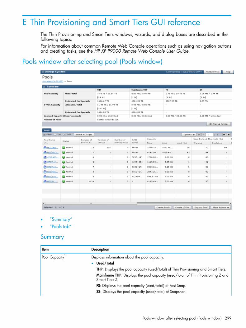
E Thin Provisioning and Smart Tiers GUI referenceThe Thin Provisioning and Smart Tiers windows, wizards, and dialog boxes are described in thefollowing topics.For information about common Remote Web Console operations such as using navigation buttonsand creating tasks, see the HP XP P9000 Remote Web Console User Guide.
Pools window after selecting pool (Pools window)
• “Summary”• “Pools tab”
Summary
DescriptionItem
Displays information about the pool capacity.Pool Capacity1
• Used/TotalTHP: Displays the pool capacity (used/total) of Thin Provisioning and Smart Tiers.Mainframe THP: Displays the pool capacity (used/total) of Thin Provisioning Z andSmart Tiers Z.FS: Displays the pool capacity (used/total) of Fast Snap.SS: Displays the pool capacity (used/total) of Snapshot.
Pools window after selecting pool (Pools window) 299

DescriptionItem
For each value, if the Estimated Configurable capacity is zero, is displayed inthe cell.
• Estimated Configurable2
THP: Displays the estimated pool capacity of Thin Provisioning and Smart Tiers.Mainframe THP: Displays the estimated pool capacity of Thin Provisioning Z andSmart Tiers Z.FS: Displays the remaining physical pool capacity that is configurable for Fast Snap.SS: Displays the remaining physical pool capacity that is configurable for Snapshot.
Displays information about the THP V-VOL capacity.V-VOL Capacity1
• Allocated/TotalTHP: In the Allocated field, total capacity of the Thin Provisioning and Smart TiersTHP V-VOLs to which LU paths are allocated is displayed. In the Total field, totalcapacity of the Thin Provisioning and Smart Tiers THP V-VOLs is displayed.Mainframe THP: In each of the Allocated and Total fields, total capacity of the ThinProvisioning Z and Smart Tiers Z THP V-VOLs is displayed.
For each value, if the Estimated Configurable capacity is zero, is displayed inthe cell.
• Estimated Configurable2
THP: Displays the THP V-VOL estimated configurable capacity of Thin Provisioningand Smart Tiers.Mainframe THP: Displays the THP V-VOL estimated configurable capacity of ThinProvisioning Z and Smart Tiers Z.
THP: Displays the licensed capacity of Thin Provisioning. Used displays the total capacityof pools for Thin Provisioning and Smart Tiers,
Licensed Capacity (Used /Licensed)
Mainframe THP: Displays the licensed capacity of Thin Provisioning Z. Used displaysthe total capacity of pools for Thin Provisioning Z and Smart Tiers Z.FS: Displays the licensed capacity of the Fast Snap.SS: Displays the licensed capacity of Business Copy and Snapshot.
CAUTION: In the Licensed Capacity(Used/Licensed) field, the total capacity of thesystem is displayed. The total capacity of the system includes capacities of LDEVsassigned to each user and resources other than LDEVs. Therefore, the value displayedas the "Used" Licensed Capacity (Used/ Licensed) might differ from the value of the"Total" Pool Capacity.
Displays the total number of pools for Thin Provisioning, Smart Tiers, Fast Snap, Snapshot,Thin Provisioning Z, and Smart Tiers Z.
Number of Pools
Displays the Edit Tiering Policies window.Edit Tiering Policies
Notes:1. The total value of the Total cells under Capacity of each pool type in the Pools tab window and the total Used
capacity of the Pool Capacity in the Summary table are almost same, but small differences might occur.The capacity used by the Mainframe THP volume is different from the capacity used by the THP volume. If thepool-VOL or THP V-VOL for Thin Provisioning or Thin Provisioning Z is created, the estimated configurable poolcapacity and estimated configurable V-VOL capacity for both THP and Mainframe THP change. The estimatedcapacity is calculated based on the configuration of current pools and THP V-VOL, and remaining capacity of theshared memory.
2. The estimated configurable capacity of Thin Provisioning or Thin Provisioning Z is the estimate of the THP V-VOLcapacity or the pool capacity that can be created by using the remaining capacity of the shared memory afterdeduction of the capacity of the shared memory used by the current pool and THP V-VOL. The values of the EstimatedConfigurable Pool Capacity and the Estimated Configurable V-VOL Capacity can be used only as a guide, but arenot guaranteed to create pools and THP V-VOLs having the estimated configurable capacity. If the pool-VOL or THPV-VOL for Thin Provisioning or Thin Provisioning Z is created or deleted, the estimated configurable pool capacityand estimated configurable V-VOL capacity for both Thin Provisioning and Thin Provisioning Z change.
300 Thin Provisioning and Smart Tiers GUI reference
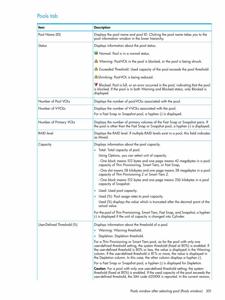
Pools tab
DescriptionItem
Displays the pool name and pool ID. Clicking the pool name takes you to thepool information window in the lower hierarchy.
Pool Name (ID)
Displays information about the pool status.Status
Normal: Pool is in a normal status.
Warning: Pool-VOL in the pool is blocked, or the pool is being shrunk.
Exceeded Threshold: Used capacity of the pool exceeds the pool threshold.
Shrinking: Pool-VOL is being reduced.
Blocked: Pool is full, or an error occurred in the pool, indicating that the poolis blocked. If the pool is in both Warning and Blocked status, only Blocked isdisplayed.
Displays the number of pool-VOLs associated with the pool.Number of Pool VOLs
Displays the number of V-VOLs associated with the pool.Number of V-VOLsFor a Fast Snap or Snapshot pool, a hyphen (-) is displayed.
Displays the number of primary volumes of the Fast Snap or Snapshot pairs. Ifthe pool is other than the Fast Snap or Snapshot pool, a hyphen (-) is displayed.
Number of Primary VOLs
Displays the RAID level. If multiple RAID levels exist in a pool, this field indicatesas Mixed.
RAID level
Displays information about the pool capacity.Capacity• Total: Total capacity of pool.
Using Options, you can select unit of capacity.- One block means 512 bytes and one page means 42 megabytes in a poolcapacity of Thin Provisioning, Smart Tiers, or Fast Snap,- One slot means 58 kilobytes and one page means 38 megabytes in a poolcapacity of Thin Provisioning Z or Smart Tiers Z.- One block means 512 bytes and one page means 256 kilobytes in a poolcapacity of Snapshot.
• Used: Used pool capacity.
• Used (%): Pool usage rates to pool capacity.Used (%) displays the value which is truncated after the decimal point of theactual value.
For the pool of Thin Provisioning, Smart Tiers, Fast Snap, and Snapshot, a hyphen(-) is displayed if the unit of capacity is changed into Cylinder.
Displays information about the threshold of a pool.User-Defined Threshold (%)• Warning: Warning threshold.
• Depletion: Depletion threshold.
For a Thin Provisioning or Smart Tiers pool, as for the pool with only oneuser-defined threshold setting, the system threshold (fixed at 80%) is enabled. Ifthe user-defined threshold is 80% or less, the value is displayed in the Warningcolumn. If the user-defined threshold is 81% or more, the value is displayed inthe Depletion column. In this case, the other column displays a hyphen (-).For a Fast Snap or Snapshot pool, a hyphen (-) is displayed for Depletion.Caution: For a pool with only one user-defined threshold setting, the systemthreshold (fixed at 80%) is enabled. If the used capacity of the pool exceeds theuser-defined threshold, the SIM code 620XXX is reported. In the current version,
Pools window after selecting pool (Pools window) 301

DescriptionItem
the system threshold cannot be set because the user must set 2 of the user-definedthresholds: Warning and Depletion.
Displays information about subscription of the pool.Subscription (%)• Current: Percentage of the total V-VOL capacity assigned to the pool.
• Limit: Percentage of the subscription limit of the pool.
For a Fast Snap or Snapshot pool, a hyphen (-) is displayed for Current andLimit.
Displays the pool type.Pool Type• For a Thin Provisioning pool, THP is displayed.
• For a Smart Tiers pool, Smart is displayed.
• For a Thin Provisioning Z pool, Mainframe THP is displayed.
• For a Smart Tiers Z pool, Mainframe Smart is displayed.
• For a Fast Snap pool, FS is displayed.
• For a Snapshot pool, SS is displayed.
Displays the hard disk drive type and RPM of the pool. If multiple drive types orRPMs exist in a pool, this field indicates that drive types or RPMs are mixed.
Drive Type/RPM
When the volume is the external volume, Drive Type displays External Storageand the value of the external LDEV tier rank.
Displays whether Smart Tiers or Smart Tiers Z is enabled or disabled. If it isenabled Auto or Manual is displayed. If it is disabled, a hyphen (-) is displayed.
Tier Management
For a Fast Snap or Snapshot pool, a hyphen (-) is displayed.
Displays the CLPR set for the Fast Snap or Snapshot pool-VOLs. Displays inID:CLPR form.
CLPR
For Pool-VOLs other than the Fast Snap or Snapshot pool-VOL, a hyphen (-) isdisplayed.
Displays whether the pool-VOL can be removed. For a Fast Snap or Snapshotpool or while the pool is being shrunk, a hyphen (-) is displayed.
Shrinkable
Displays the monitoring mode that is set for the pool. If the continuous mode isenabled, Continuous Mode is displayed. If the period mode is enabled, Period
Monitoring Mode
Mode is displayed. If Smart Tiers or Smart Tiers Z is disabled, a hyphen (-) isdisplayed.
Displays the status of pool monitoring.Monitoring Status• In Progress: The monitoring is being performed.
• During Computation: The calculating is being processed.
Other than these cases, a hyphen (-) is displayed.
Displays the latest monitoring data.Recent Monitor Data• If the monitoring data exists, the monitoring period of time is displayed.
Example: 2010/11/15 00:00 - 2010/11/15 23:59
• If the monitoring data is being obtained, only the starting time is displayed.Example: 2010/11/15 00:00 -
• If the latest monitoring data does not exist, a hyphen (-) is displayed.
Displays the pool management task being performed to the pool.Pool Management Task• Waiting for Rebalance: The rebalance process is being waited.
• Rebalancing: The rebalance process is being performed.
• Waiting for Relocation: The tier relocation process is being waited.
302 Thin Provisioning and Smart Tiers GUI reference

DescriptionItem
• Relocating: The tier relocation process is being performed.
• Waiting for Shrink: The pool shrinking process is being waited.
• Shrinking: The pool shrinking process is being performed.
• Hyphen (-): The pool management task is not being performed to the pool.If the Fast Snap or Snapshot pool is displayed, a hyphen (-) appears.
For details about the tier relocation, see the tier relocation log file. For detailsabout the table items of the tier relocation log file, see “Tier relocation log filecontents” (page 107).
Displays the status of the tier relocation processing.Relocation Result• In Progress: The status of Pool Management Task is Waiting for Relocation
or Relocating.• Completed: The tier relocation operation is not in progress, or the tier
relocation is complete.• Uncompleted (n% relocated): The tier relocation is suspended at the indicated
percentage progression.• Hyphen (-): The pool is not a Smart Tiers or Smart Tiers Z pool.
Indicates whether pool-VOLs of different RAID levels can coexist in a pool.Mixable1
• Enabled: Pool-VOLs of different RAID levels can coexist in the pool. For detailsabout the requirements, see “Pool-VOL requirements” (page 76).
• Disabled: Pool-VOLs of different RAID levels cannot coexist in the pool.
• Hyphen (-): The pool is a Fast Snap or Snapshot pool.
Displays the Create Pools window.Create Pools
Displays the Create LDEVs window.Create LDEVs
Displays the Expand Pool window.Expand Pool
Displays the Delete Pools window.Delete Pools2
Displays the Restore Pools window.Restore Pools2
Displays the Edit Pools window.Edit Pools2
Displays the Monitor Pools window.Monitor Pools2
Displays the Stop Monitoring Pools window.Stop Monitoring Pools2
Displays the Start Tier Relocation window.Start Tier Relocation2
Displays the Stop Tier Relocation window.Stop Tier Relocation2
Displays the Complete SIMs window.Complete SIMs2
Displays the View Tier Properties window. This window can be viewed only forthe pools for which Smart Tiers or Smart Tiers Z is enabled.
View Tier Properties2
Displays the View Pool Management Status window.View Pool Management Status2
Displays the window for outputting table information.Export2
Displays the window to download the result of the tier relocation. For moreinformation about the table item of the tier relocation file, see “Tier relocationlog file contents” (page 107).
Tier Relocation Log2
Notes:1. Does not appear by default. To display this item, change settings in the Column Settings window of the table option.
For details about the Column Settings window, see the HP XP P9000 Remote Web Console User Guide.2. Appears when you click More Actions.
Pools window after selecting pool (Pools window) 303
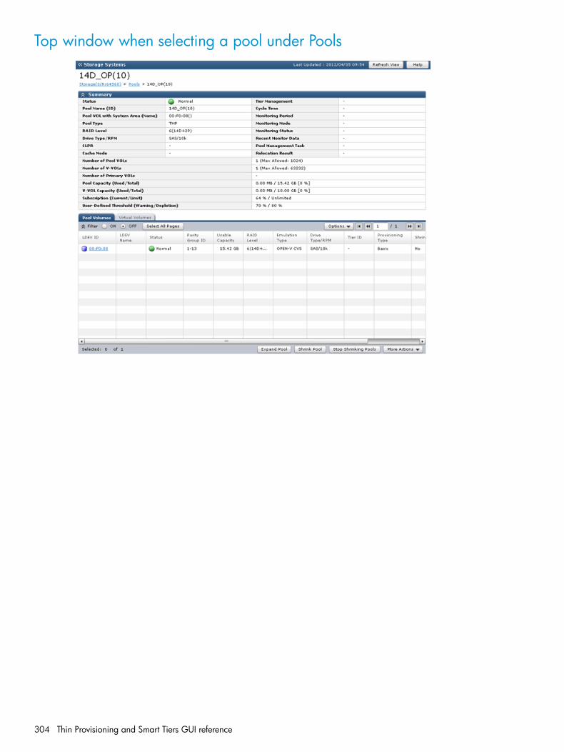
Top window when selecting a pool under Pools
304 Thin Provisioning and Smart Tiers GUI reference

• “Summary”• “Pool Volumes tab”• “Virtual Volumes tab”• “Primary Volumes tab”
Summary
DescriptionItem
Displays information about the pool status.Status
Normal: Pool is in a normal status.
Warning: Pool-VOL in the pool is blocked, or the pool is being shrunk.
Exceeded Threshold: Used capacity of the pool exceeds the pool threshold.
Shrinking: Pool-VOL is being reduced.
Blocked: The pool is full, or an error occurred in the pool, indicating thatthe pool is blocked. If the pool is in both Warning and Blocked status, onlyBlocked is displayed.
Displays the pool name and pool ID.Pool Name (ID)
Top window when selecting a pool under Pools 305
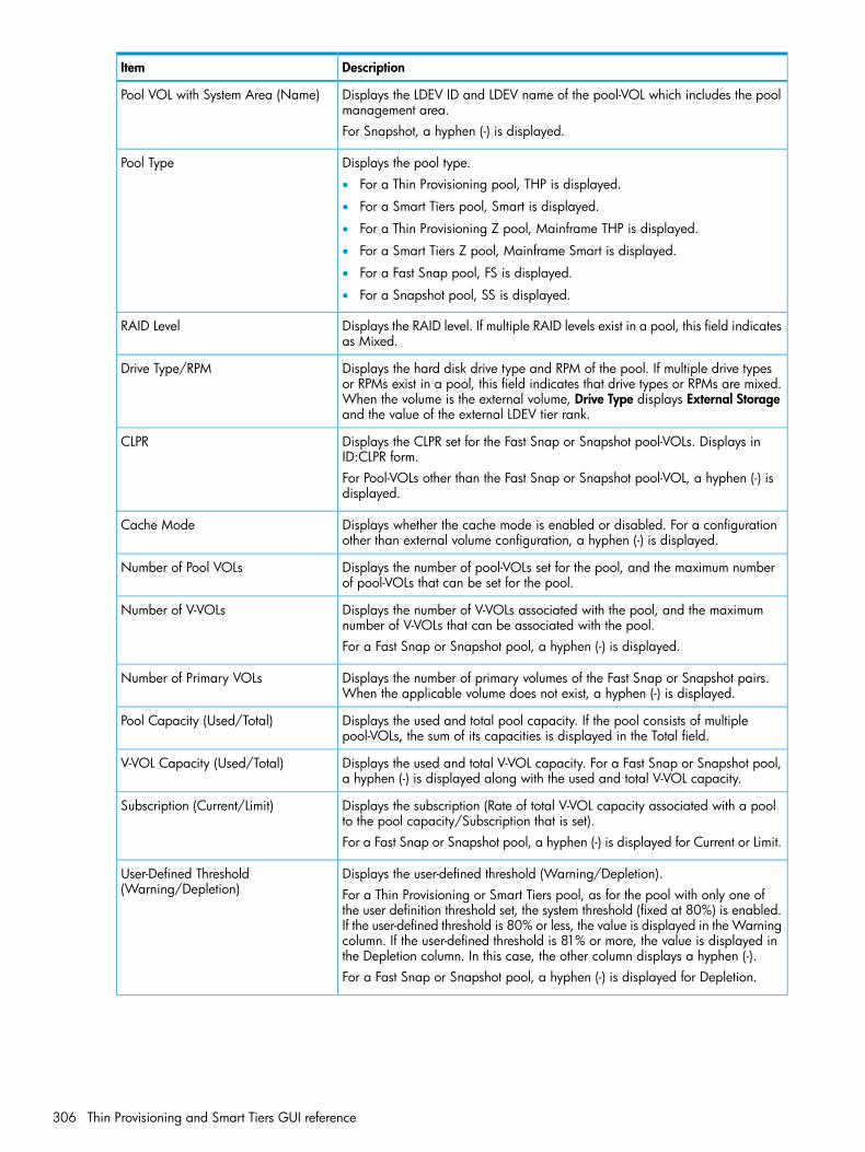
DescriptionItem
Displays the LDEV ID and LDEV name of the pool-VOL which includes the poolmanagement area.
Pool VOL with System Area (Name)
For Snapshot, a hyphen (-) is displayed.
Displays the pool type.Pool Type• For a Thin Provisioning pool, THP is displayed.
• For a Smart Tiers pool, Smart is displayed.
• For a Thin Provisioning Z pool, Mainframe THP is displayed.
• For a Smart Tiers Z pool, Mainframe Smart is displayed.
• For a Fast Snap pool, FS is displayed.
• For a Snapshot pool, SS is displayed.
Displays the RAID level. If multiple RAID levels exist in a pool, this field indicatesas Mixed.
RAID Level
Displays the hard disk drive type and RPM of the pool. If multiple drive typesor RPMs exist in a pool, this field indicates that drive types or RPMs are mixed.
Drive Type/RPM
When the volume is the external volume, Drive Type displays External Storageand the value of the external LDEV tier rank.
Displays the CLPR set for the Fast Snap or Snapshot pool-VOLs. Displays inID:CLPR form.
CLPR
For Pool-VOLs other than the Fast Snap or Snapshot pool-VOL, a hyphen (-) isdisplayed.
Displays whether the cache mode is enabled or disabled. For a configurationother than external volume configuration, a hyphen (-) is displayed.
Cache Mode
Displays the number of pool-VOLs set for the pool, and the maximum numberof pool-VOLs that can be set for the pool.
Number of Pool VOLs
Displays the number of V-VOLs associated with the pool, and the maximumnumber of V-VOLs that can be associated with the pool.
Number of V-VOLs
For a Fast Snap or Snapshot pool, a hyphen (-) is displayed.
Displays the number of primary volumes of the Fast Snap or Snapshot pairs.When the applicable volume does not exist, a hyphen (-) is displayed.
Number of Primary VOLs
Displays the used and total pool capacity. If the pool consists of multiplepool-VOLs, the sum of its capacities is displayed in the Total field.
Pool Capacity (Used/Total)
Displays the used and total V-VOL capacity. For a Fast Snap or Snapshot pool,a hyphen (-) is displayed along with the used and total V-VOL capacity.
V-VOL Capacity (Used/Total)
Displays the subscription (Rate of total V-VOL capacity associated with a poolto the pool capacity/Subscription that is set).
Subscription (Current/Limit)
For a Fast Snap or Snapshot pool, a hyphen (-) is displayed for Current or Limit.
Displays the user-defined threshold (Warning/Depletion).User-Defined Threshold(Warning/Depletion) For a Thin Provisioning or Smart Tiers pool, as for the pool with only one of
the user definition threshold set, the system threshold (fixed at 80%) is enabled.If the user-defined threshold is 80% or less, the value is displayed in the Warningcolumn. If the user-defined threshold is 81% or more, the value is displayed inthe Depletion column. In this case, the other column displays a hyphen (-).For a Fast Snap or Snapshot pool, a hyphen (-) is displayed for Depletion.
306 Thin Provisioning and Smart Tiers GUI reference

DescriptionItem
Tier Management • If Smart Tiers or Smart Tiers Z is enabled, Auto or Manual is displayed.
• If Smart Tiers or Smart Tiers Z is disabled, a hyphen (-) is displayed.
• For a Fast Snap or Snapshot pool, a hyphen (-) is displayed.
Displays the cycle of performance monitoring and tier relocation. If Smart Tiersor Smart Tiers Z is disabled, a hyphen (-) is displayed.
Cycle Time
Displays the time of starting and ending of performance monitoring. If SmartTiers or Smart Tiers Z is disabled, a hyphen (-) is displayed.
Monitoring Period
Displays the monitoring mode that is set for the pool. If the continuous mode isenabled, Continuous Mode is displayed. If the period mode is enabled, Period
Monitoring Mode
Mode is displayed. If Smart Tiers or Smart Tiers Z is disabled, a hyphen (-) isdisplayed.
Displays the status of pool monitoring.Monitoring StatusIf the monitoring is being performed, In Progress is displayed. A hyphen (-) isdisplayed other than this case.
Displays the latest monitoring data.Recent Monitor Data• If the monitoring data exists, the monitoring period of time is displayed.
Example: 2010/11/15 00:00 - 2010/11/15 23:59
• If the monitoring data is being obtained, only the starting time is displayed.Example: 2010/11/15 00:00 -
• If the latest monitoring data does not exist, a hyphen (-) is displayed.
Displays the pool management task being performed to the pool.Pool Management Task• Waiting for Rebalance: The rebalance process is being waited.
• Rebalancing: The rebalance process is being performed.
• Waiting for Relocation: The tier relocation process is being waited.
• Relocating: The tier relocation process is being performed.
• Waiting for Shrink: The pool shrinking process is being waited.
• Shrinking: The pool shrinking process is being performed.
• Hyphen (-): The pool management task is not being performed to the pool.If the Fast Snap or Snapshot pool is displayed, a hyphen (-) appears.
For details about the tier relocation, see the tier relocation log file. For detailsabout the table items of the tier relocation log file, see “Tier relocation log filecontents” (page 107).
Displays the status of the tier relocation processing.Relocation Result• In Progress: The status of Pool Management Task is Waiting for Relocation
or Relocating.• Completed: The tier relocation operation is not in progress, or the tier
relocation is complete.• Uncompleted (n% relocated): The tier relocation is suspended at the indicated
percentage progression.• Hyphen (-): The pool is not a Smart Tiers or Smart Tiers Z pool.
Top window when selecting a pool under Pools 307
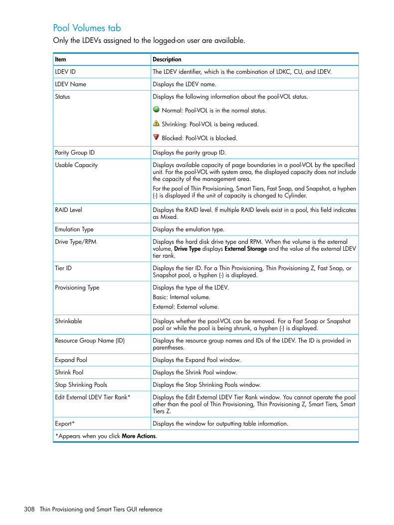
Pool Volumes tabOnly the LDEVs assigned to the logged-on user are available.
DescriptionItem
The LDEV identifier, which is the combination of LDKC, CU, and LDEV.LDEV ID
Displays the LDEV name.LDEV Name
Displays the following information about the pool-VOL status.Status
Normal: Pool-VOL is in the normal status.
Shrinking: Pool-VOL is being reduced.
Blocked: Pool-VOL is blocked.
Displays the parity group ID.Parity Group ID
Displays available capacity of page boundaries in a pool-VOL by the specifiedunit. For the pool-VOL with system area, the displayed capacity does not includethe capacity of the management area.
Usable Capacity
For the pool of Thin Provisioning, Smart Tiers, Fast Snap, and Snapshot, a hyphen(-) is displayed if the unit of capacity is changed to Cylinder.
Displays the RAID level. If multiple RAID levels exist in a pool, this field indicatesas Mixed.
RAID Level
Displays the emulation type.Emulation Type
Displays the hard disk drive type and RPM. When the volume is the externalvolume, Drive Type displays External Storage and the value of the external LDEVtier rank.
Drive Type/RPM
Displays the tier ID. For a Thin Provisioning, Thin Provisioning Z, Fast Snap, orSnapshot pool, a hyphen (-) is displayed.
Tier ID
Displays the type of the LDEV.Provisioning TypeBasic: Internal volume.External: External volume.
Displays whether the pool-VOL can be removed. For a Fast Snap or Snapshotpool or while the pool is being shrunk, a hyphen (-) is displayed.
Shrinkable
Displays the resource group names and IDs of the LDEV. The ID is provided inparentheses.
Resource Group Name (ID)
Displays the Expand Pool window.Expand Pool
Displays the Shrink Pool window.Shrink Pool
Displays the Stop Shrinking Pools window.Stop Shrinking Pools
Displays the Edit External LDEV Tier Rank window. You cannot operate the poolother than the pool of Thin Provisioning, Thin Provisioning Z, Smart Tiers, SmartTiers Z.
Edit External LDEV Tier Rank*
Displays the window for outputting table information.Export*
*Appears when you click More Actions.
308 Thin Provisioning and Smart Tiers GUI reference

Virtual Volumes tabThis tab is displayed unless you select a Fast Snap or Snapshot pool.
DescriptionItem
The LDEV identifier, which is the combination of LDKC, CU, and LDEV.LDEV ID
Displays the LDEV name.LDEV Name
Normal: Normal status.Status
Blocked: Host cannot access a blocked volume.
Warning: Problem occurs in the volume.
Formatting: Volume is being formatted.
Preparing Quick Format: Volume is being prepared for quick formatting.
Quick Formatting: Volume is being quick-formatted.
Correction Access: Access attribute is being corrected.
Copying: Data in the volume is being copied.
Read Only: Data cannot be written to a read-only volume.
Shredding: Volume is being shredded.
Hyphen (-): Any status other than the above.
Displays the emulation type.Emulation Type
Displays the V-VOL capacity.Capacity - Total
Displays the V-VOL used capacity.Capacity - UsedThe displayed value on Total might be larger than the displayed value on Useddue to following reasons:
• Used displays the used V-VOL capacity which is rounded up on each page.
• If the emulation type is 3390-A, the used capacity of V-VOL includes thecapacity of control cylinders (7 Cyl is required per 1,113 Cyl).
Displays the V-VOL usage level.Capacity - Used(%)
Displays the V-VOL capacity in the specified unit.CapacityTotal: Displays the V-VOL total capacity.Used: Displays the V-VOL used capacity.Used (%): Displays the V-VOL usage rate.* The V-VOL used capacity is calculated, being rounded up for each page.Therefore, the total capacity might be displayed as the larger value than theused capacity.
Displays the number of alternate paths. A hyphen(-) is displayed for the ThinProvisioning Z or Smart Tiers Z V-VOL.
Number of Paths
Displays the CLPR ID.CLPR
Displays the tiering policy name and ID.Tiering PolicyAll(0): Policy set when all tiers in the pool are used.Level1(1) - Level31(31): One of the policies from Level1 to Level31 is set.Hyphen (-): V-VOL is not the Smart Tiers or Smart Tiers Z V-VOL.
Displays the new page assignment tier.New Page Assignment Tier
Top window when selecting a pool under Pools 309

DescriptionItem
High: High is set to V-VOL.Middle: Middle is set to V-VOL.Low: Low is set to V-VOL.Hyphen (-): V-VOL is not the Smart Tiers V-VOL.
Displays whether tier relocation is set to enabled or disabled. If the Smart Tiersor Smart Tiers Z V-VOL is not used, a hyphen (-) is displayed.
Tier Relocation
Displays the relocation priority.Relocation Priority• Prioritized: The priority is set to V-VOL.
• Blank: The priority is not set to V-VOL.
• Hyphen (-): V-VOL is not the Smart Tiers or Smart Tiers Z V-VOL or the tierrelocation function is disabled.
Displays the pool management task being performed to the pool.Pool Management Task• Waiting for Rebalance: The rebalance process is being waited.
• Rebalancing: The rebalance process is being performed.
• Waiting for Relocation: The tier relocation process is being waited.
• Relocating: The tier relocation process is being performed.
• Waiting for Shrink: The pool shrinking process is being waited.
• Shrinking: The pool shrinking process is being performed.
• Hyphen (-): The pool management task is not being performed to the pool.
Displays the V-VOL management task being performed to V-VOL.V-VOL Management Task• Reclaiming Zero Pages: The zero page reclaiming processing is being
performed.• Waiting for Zero Page Reclaiming: The zero page reclaiming processing is
being waited.• Hyphen (-): The V-VOL management task is not being performed to V-VOL.
Displays the attribute of the LDEV.AttributeTSE: TSE-VOL.Hyphen (-): Volume in which the attribute is not defined.
Displays the access attribute of the LDEV.Access Attribute1
Displays the resource group names and IDs of the LDEV. The ID is provided inparentheses.
Resource Group Name (ID)
Displays the Create LDEV window.Create LDEVs
Displays the Add LUN Paths window. If Mainframe THP or Smart is displayedin the Pool Type, you cannot select this item.
Add LUN Paths
Displays the Expand V-VOLs window.Expand V-VOLs
Displays the Format LDEVs window.Format LDEVs2
Displays the Delete LDEVs window.Delete LDEVs2
Displays the Shred LDEVs window.Shred LDEVs2
Displays the Delete LUN Paths window.Delete LUN Paths2
Displays the Block LDEVs window.Block LDEVs2
Displays the Restore LDEVs window.Restore LDEVs2
Displays the Edit LDEVs window.Edit LDEVs2
310 Thin Provisioning and Smart Tiers GUI reference

DescriptionItem
Displays the Reclaim Zero Pages window.Reclaim Zero Pages2
Displays the Stop Reclaiming Zero Pages window.Stop Reclaiming Zero Pages2
Displays the View Tier Properties window. This window can open only for apool for which Smart Tiers is enabled.
View Tier Properties2
Displays the View Pool Management Status window.View Pool Management Status2
For a Snapshot pool, nothing is displayed.
Displays the window for outputting table information.Export2
1Does not appear by default. To display this item, change the Column Settings of the table option. For details aboutthe Column Settings window, see the HP P9000 Remote Web Console User Guide.2Appears when you click More Actions.
Primary Volumes tabIf you select a Fast Snap or Snapshot pool, this tab is displayed.
DescriptionItem
Displays the combination of the LDKC, CU, and LDEV.LDEV IDClicking LDEV ID opens the LDEV Properties window.
Displays the LDEV name.LDEV Name
Normal: Normal status.Status
Blocked: Host cannot access a blocked volume.
Warning: Problem occurs in the volume.
Formatting: Volume is being formatted.
Preparing Quick Format: Volume is being prepared for quick formatting.
Quick Formatting: Volume is being quick-formatted.
Correction Access: Access attribute is being corrected.
Copying: Data in the volume is being copied.
Read Only: Data cannot be written to a read-only volume.
Shredding: Volume is being shredded.
Hyphen (-): Any status other than the above.
Displays the emulation type.Emulation Type
Displays the used pool capacity.Used Pool Capacity
Displays the pool usage level.Pool Usage(%)
Displays the number of alternate paths.Number of Paths
Displays the CLPR. Displays in ID:CLPR form.CLPR
Displays the window for outputting table information.Export
Top window when selecting a pool under Pools 311

Create Pools wizard
Create Pools windowUse this window to create new pools for Thin Provisioning, Fast Snap, or Snapshot.
CAUTION: When you create the Thin Provisioning or Thin Provisioning Z pool, if you specifyAny for RAID level to display the Select Pool VOLs window, external volumes with the cache modeset to disabled are not displayed in the Available Pool Volumes table because they cannot coexistwith volumes of the other RAID levels:When you select these volumes in the Select Pool VOLs window, specify a hyphen (-) for RAID level.
312 Thin Provisioning and Smart Tiers GUI reference

Setting fields
DescriptionItem
Select the pool type.*Pool TypeFor Fast Snap, select Fast Snap. For Snapshot, select snapshot.For following program products, select Thin Provisioning.
• Thin Provisioning
• Smart Tiers
Create Pools wizard 313

DescriptionItem
• Thin Provisioning Z
• Smart Tiers Z
Select the system type.*System TypeIf you select Fast Snap or Snapshot, only Open is displayed.
If Thin Provisioning is selected for the pool type, you can enable or disable SmartPool. If it is set to enabled, Smart Tiers or Smart Tiers Z is enabled.
*Smart Pool
Select the hard disk drive type and RPM of the pool-VOL. Mixable appears.When the volume is the external volume, Drive Type displays External Storage.
*Drive Type/RPM
Select the RAID level of the pool-VOL.*RAID LevelMixable appears in the case of Thin Provisioning or Smart Tiers. A hyphen (-)appears when External Storage is selected in the Drive Type/RPM list.
Opens the Select Pool VOLs window. Selecting a pool-VOL is mandatory.*Select Pool VOLs
Displays the total number of the selected pool-VOLs.Total Selected Pool Volumes
Displays the total capacity of the selected pool-VOLs.Total Selected Capacity
The set the pool name.*Pool Name• Prefix: Enter the alphanumeric characters, which are fixed characters of the
head of the pool name. The characters are case-sensitive.• Initial Number: Enter the initial number following the prefix name, which can
be entered up to 9 digits.• You can enter up to 32 characters including the initial number.
The smallest available number is entered in the text box as a default. No numberappears in the text box if no available pool ID exists.
Initial Pool ID
If you specify the pool ID which is used already, the minimum pool ID after thatthe specified pool ID is automatically set.
Set the subscription limit of the pool from 0 to 65534 (%).Subscription LimitIf this is blank, the subscription is set to unlimited.When creating a Fast Snap or Snapshot pool, this setting is not necessary.
Set the threshold between 1 and 100%. The default value is 70%.Warning ThresholdFor Fast Snap or Snapshot: Set the threshold between 20% and 95%. The defaultvalue is 80%.
Set the threshold between 1% and 100%. The default value is 80%.Depletion ThresholdWhen creating a Fast Snap or Snapshot pool, this setting is not necessary.
Select Auto or Manual of performance monitoring and tier relocation.Tier Management• Cycle Time
Select the cycle of performance monitoring and tier relocation.
• Monitoring PeriodWhen 24 Hours is selected in the Cycle Time list, specify the time zone from00:00 to 23:59 (default value), in which performance monitoring is to beperformed. Take one or more hours between the starting time and the endingtime. If you specify the starting time later than the ending time, the performancemonitoring continues until the time when you specify as the ending time onthe next day.
This function can be set when the Smart Pool is enabled.
Specifies the monitoring mode, If you perform the tier relocation weighted to thepast period monitoring result, select Continuous Mode. If you perform the tier
Monitoring Mode
314 Thin Provisioning and Smart Tiers GUI reference
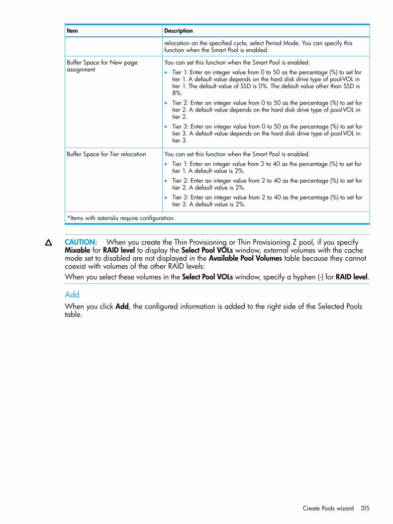
DescriptionItem
relocation on the specified cycle, select Period Mode. You can specify thisfunction when the Smart Pool is enabled.
You can set this function when the Smart Pool is enabled.Buffer Space for New pageassignment • Tier 1: Enter an integer value from 0 to 50 as the percentage (%) to set for
tier 1. A default value depends on the hard disk drive type of pool-VOL intier 1. The default value of SSD is 0%. The default value other than SSD is8%.
• Tier 2: Enter an integer value from 0 to 50 as the percentage (%) to set fortier 2. A default value depends on the hard disk drive type of pool-VOL intier 2.
• Tier 3: Enter an integer value from 0 to 50 as the percentage (%) to set fortier 3. A default value depends on the hard disk drive type of pool-VOL intier 3.
You can set this function when the Smart Pool is enabled.Buffer Space for Tier relocation• Tier 1: Enter an integer value from 2 to 40 as the percentage (%) to set for
tier 1. A default value is 2%.• Tier 2: Enter an integer value from 2 to 40 as the percentage (%) to set for
tier 2. A default value is 2%.• Tier 3: Enter an integer value from 2 to 40 as the percentage (%) to set for
tier 3. A default value is 2%.
*Items with asterisks require configuration.
CAUTION: When you create the Thin Provisioning or Thin Provisioning Z pool, if you specifyMixable for RAID level to display the Select Pool VOLs window, external volumes with the cachemode set to disabled are not displayed in the Available Pool Volumes table because they cannotcoexist with volumes of the other RAID levels:When you select these volumes in the Select Pool VOLs window, specify a hyphen (-) for RAID level.
AddWhen you click Add, the configured information is added to the right side of the Selected Poolstable.
Create Pools wizard 315
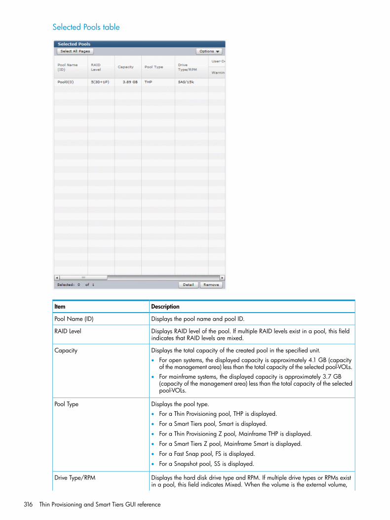
Selected Pools table
DescriptionItem
Displays the pool name and pool ID.Pool Name (ID)
Displays RAID level of the pool. If multiple RAID levels exist in a pool, this fieldindicates that RAID levels are mixed.
RAID Level
Displays the total capacity of the created pool in the specified unit.Capacity• For open systems, the displayed capacity is approximately 4.1 GB (capacity
of the management area) less than the total capacity of the selected pool-VOLs.• For mainframe systems, the displayed capacity is approximately 3.7 GB
(capacity of the management area) less than the total capacity of the selectedpool-VOLs.
Displays the pool type.Pool Type• For a Thin Provisioning pool, THP is displayed.
• For a Smart Tiers pool, Smart is displayed.
• For a Thin Provisioning Z pool, Mainframe THP is displayed.
• For a Smart Tiers Z pool, Mainframe Smart is displayed.
• For a Fast Snap pool, FS is displayed.
• For a Snapshot pool, SS is displayed.
Displays the hard disk drive type and RPM. If multiple drive types or RPMs existin a pool, this field indicates Mixed. When the volume is the external volume,
Drive Type/RPM
316 Thin Provisioning and Smart Tiers GUI reference

DescriptionItem
Drive Type displays External Storage and the value of the external LDEV tierrank.
Displays the pool threshold.User-Defined Threshold (%)• Warning: Warning threshold is displayed.
• Depletion: Depletion threshold is displayed.
For a Fast Snap or Snapshot pool, a hyphen (-) is displayed for Depletion.
Displays subscription limit of the pool.Subscription Limit (%)For Fast Snap or Snapshot pool, a hyphen (-) is displayed.
Displays the number of pool-VOLs.Number of Pool VOLs
Displays the Smart Tiers or Smart Tiers Z information.Smart Pool• Monitoring Mode
If the continuous mode is enabled, Continuous Mode is displayed. If theperiod mode is enabled, Period Mode is displayed.
• Tier ManagementIf Smart Tiers or Smart Tiers Z is enabled, Auto or Manual of performancemonitoring and tier relocation is displayed. If Smart Tiers or Smart Tiers Z isdisabled, a hyphen (-) is displayed.
• Cycle TimeDisplays the cycle of performance monitoring and tier relocation. If SmartTiers or Smart Tiers Z is disabled, a hyphen (-) is displayed.
• Monitoring PeriodDisplays the time zone of performance monitoring when 24 Hours is selectedin the Cycle Time list. If Smart Tiers or Smart Tiers Z is disabled, a hyphen (-)is displayed.
Displays the information of the buffer space for new page assignment to eachtier.
Buffer Space for New pageassignment (%)
• Tier 1: If you make the Smart Tiers or Smart Tiers Z function available, thebuffer space for new page assignment to tier 1 is displayed. If you make theSmart Tiers or Smart Tiers Z function unavailable, a hyphen (-) is displayed.
• Tier 2: If you make the Smart Tiers or Smart Tiers Z function available, andtier 2 exists, the buffer space for new page assignment to tier 2 is displayed.If you make the Smart Tiers or Smart Tiers Z function unavailable, or tier 2does not exist, a hyphen (-) is displayed.
• Tier 3: If you make the Smart Tiers or Smart Tiers Z function available, andtier 3 exists, the buffer space for new page assignment to tier 3 is displayed.If you make the Smart Tiers or Smart Tiers Z function unavailable, or tier 3does not exist, a hyphen (-) is displayed.
Displays the information of the buffer space for tier relocation to each tier.Buffer Space for Tier relocation (%)• Tier 1: If you make the Smart Tiers or Smart Tiers Z function available, the
buffer space for tier relocation to tier 1 is displayed. If you make the SmartTiers or Smart Tiers Z function unavailable, a hyphen (-) is displayed.
• Tier 2: If you make the Smart Tiers or Smart Tiers Z function available, andtier 2 exists, the buffer space for tier relocation to tier 2 is displayed. If youmake the Smart Tiers or Smart Tiers Z function unavailable, or tier 2 does notexist, a hyphen (-) is displayed.
• Tier 3: If you make the Smart Tiers or Smart Tiers Z function available, andtier 3 exists, the buffer space for tier relocation to tier 3 is displayed. If youmake the Smart Tiers or Smart Tiers Z function unavailable, or tier 3 does notexist, a hyphen (-) is displayed.
Create Pools wizard 317
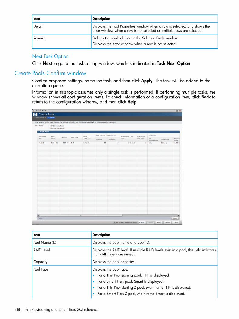
DescriptionItem
Displays the Pool Properties window when a row is selected, and shows theerror window when a row is not selected or multiple rows are selected.
Detail
Deletes the pool selected in the Selected Pools window.RemoveDisplays the error window when a row is not selected.
Next Task OptionClick Next to go to the task setting window, which is indicated in Task Next Option.
Create Pools Confirm windowConfirm proposed settings, name the task, and then click Apply. The task will be added to theexecution queue.Information in this topic assumes only a single task is performed. If performing multiple tasks, thewindow shows all configuration items. To check information of a configuration item, click Back toreturn to the configuration window, and then click Help
DescriptionItem
Displays the pool name and pool ID.Pool Name (ID)
Displays the RAID level. If multiple RAID levels exist in a pool, this field indicatesthat RAID levels are mixed.
RAID Level
Displays the pool capacity.Capacity
Displays the pool type.Pool Type• For a Thin Provisioning pool, THP is displayed.
• For a Smart Tiers pool, Smart is displayed.
• For a Thin Provisioning Z pool, Mainframe THP is displayed.
• For a Smart Tiers Z pool, Mainframe Smart is displayed.
318 Thin Provisioning and Smart Tiers GUI reference
DescriptionItem
• For a Fast Snap pool, FS is displayed.
• For a Snapshot pool, SS is displayed.
Displays the hard disk drive type and RPM. If multiple drive types or RPMs existin a pool, this field indicates that drive types or RPMs are mixed. When the
Drive Type/RPM
volume is the external volume, Drive Type displays External Storage and thevalue of the external LDEV tier rank.
Displays the pool threshold.User-Defined Threshold (%)• Warning: Warning threshold is displayed.
• Depletion: Depletion threshold is displayed.
For a Fast Snap or Snapshot pool, a hyphen (-) is displayed for Depletion.
Displays the subscription limit.Subscription Limit (%)For Fast Snap or Snapshot pool, a hyphen (-) is displayed.
Displays the number of pool-VOLs.Number of Pool VOLs
Displays the Smart Tiers or Smart Tiers Z information.Smart Pool• Monitoring Mode
If the continuous mode is enabled, Continuous Mode is displayed. If theperiod mode is enabled, Period Mode is displayed.
• Tier ManagementIf Smart Tiers or Smart Tiers Z is enabled, Auto or Manual of performancemonitoring and tier relocation is displayed. If Smart Tiers or Smart Tiers Z isdisabled, a hyphen (-) is displayed.
• Cycle TimeDisplays the cycle of performance monitoring and tier relocation. If SmartTiers or Smart Tiers Z is disabled, a hyphen (-) is displayed.
• Monitoring PeriodDisplays the time zone of performance monitoring when 24 Hours is selectedin the Cycle Time list. If Smart Tiers or Smart Tiers Z is disabled, a hyphen (-)is displayed.
Displays the information of the buffer space for new page assignment to eachtier.
Buffer Space for New pageassignment (%)
• Tier 1: If you make the Smart Tiers or Smart Tiers Z function available, thebuffer space for new page assignment to tier 1 is displayed. If you make theSmart Tiers or Smart Tiers Z function unavailable, a hyphen (-) is displayed.
• Tier 2: If you make the Smart Tiers or Smart Tiers Z function available, andtier 2 exists, the buffer space for new page assignment to tier 2 is displayed.If you make the Smart Tiers or Smart Tiers Z function unavailable, or tier 2does not exist, a hyphen (-) is displayed.
• Tier 3: If you make the Smart Tiers or Smart Tiers Z function available, andtier 3 exists, the buffer space for new page assignment to tier 3 is displayed.If you make the Smart Tiers or Smart Tiers Z function unavailable, or tier 3does not exist, a hyphen (-) is displayed.
Displays the information of the buffer space for tier relocation to each tier.Buffer Space for Tier relocation (%)• Tier 1: If you make the Smart Tiers or Smart Tiers Z function available, the
buffer space for tier relocation to tier 1 is displayed. If you make the SmartTiers or Smart Tiers Z function unavailable, a hyphen (-) is displayed.
• Tier 2: If you make the Smart Tiers or Smart Tiers Z function available, andtier 2 exists, the buffer space for tier relocation to tier 2 is displayed. If you
Create Pools wizard 319
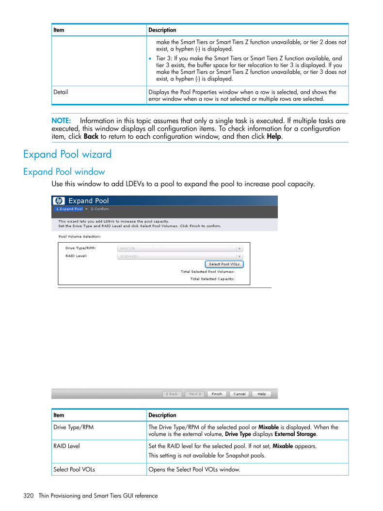
DescriptionItem
make the Smart Tiers or Smart Tiers Z function unavailable, or tier 2 does notexist, a hyphen (-) is displayed.
• Tier 3: If you make the Smart Tiers or Smart Tiers Z function available, andtier 3 exists, the buffer space for tier relocation to tier 3 is displayed. If youmake the Smart Tiers or Smart Tiers Z function unavailable, or tier 3 does notexist, a hyphen (-) is displayed.
Displays the Pool Properties window when a row is selected, and shows theerror window when a row is not selected or multiple rows are selected.
Detail
NOTE: Information in this topic assumes that only a single task is executed. If multiple tasks areexecuted, this window displays all configuration items. To check information for a configurationitem, click Back to return to each configuration window, and then click Help.
Expand Pool wizard
Expand Pool windowUse this window to add LDEVs to a pool to expand the pool to increase pool capacity.
DescriptionItem
The Drive Type/RPM of the selected pool or Mixable is displayed. When thevolume is the external volume, Drive Type displays External Storage.
Drive Type/RPM
Set the RAID level for the selected pool. If not set, Mixable appears.RAID LevelThis setting is not available for Snapshot pools.
Opens the Select Pool VOLs window.Select Pool VOLs
320 Thin Provisioning and Smart Tiers GUI reference

DescriptionItem
The total number of the pool-VOLs selected for this pool.Total Selected Pool Volumes
The total capacity of the pool-VOLs selected for this pool.Total Selected Capacity
CAUTION: When you create the Thin Provisioning pool, if you specify Mixable for RAID level todisplay the Select Pool VOLs window, external volumes with the cache mode set to disabled arenot displayed in the Available Pool Volumes table because they cannot coexist with volumes ofthe other RAID levels:When you select these volumes in the Select Pool VOLs window, specify a hyphen (-) for RAID level.
Expand Pool Confirm windowConfirm proposed settings, name the task, and then click Apply. The task will be added to theexecution queue.
Selected Pool table
DescriptionItem
Displays the pool name and pool ID.Pool Name (ID)
Selected Pool Volumes table
DescriptionItem
Displays LDEV identifier, which is the combination of LDKC, CU, and LDEV.LDEV ID
Displays the LDEV name.LDEV Name
Displays the pool-VOL capacity.Capacity
Displays the parity group ID.Parity Group ID
Expand Pool wizard 321
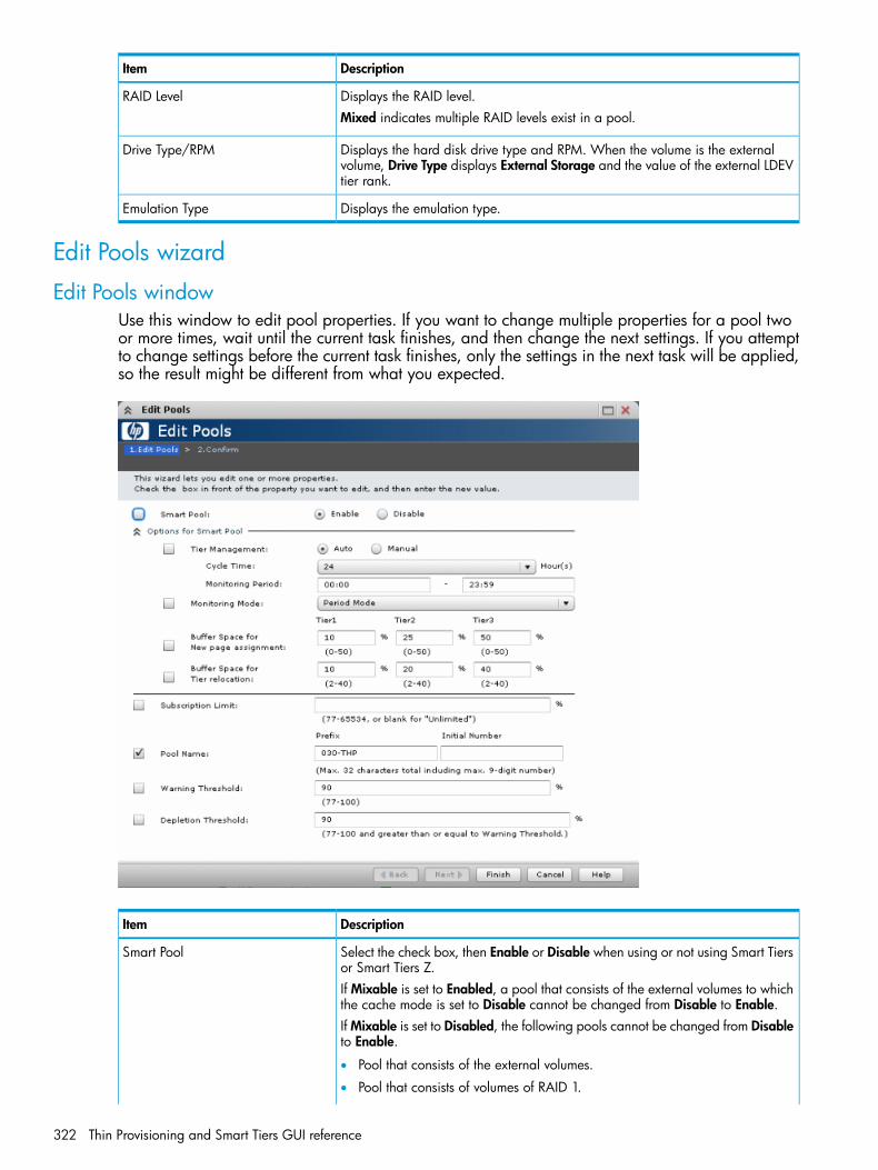
DescriptionItem
Displays the RAID level.RAID LevelMixed indicates multiple RAID levels exist in a pool.
Displays the hard disk drive type and RPM. When the volume is the externalvolume, Drive Type displays External Storage and the value of the external LDEVtier rank.
Drive Type/RPM
Displays the emulation type.Emulation Type
Edit Pools wizard
Edit Pools windowUse this window to edit pool properties. If you want to change multiple properties for a pool twoor more times, wait until the current task finishes, and then change the next settings. If you attemptto change settings before the current task finishes, only the settings in the next task will be applied,so the result might be different from what you expected.
DescriptionItem
Select the check box, then Enable or Disable when using or not using Smart Tiersor Smart Tiers Z.
Smart Pool
If Mixable is set to Enabled, a pool that consists of the external volumes to whichthe cache mode is set to Disable cannot be changed from Disable to Enable.If Mixable is set to Disabled, the following pools cannot be changed from Disableto Enable.
• Pool that consists of the external volumes.
• Pool that consists of volumes of RAID 1.
322 Thin Provisioning and Smart Tiers GUI reference
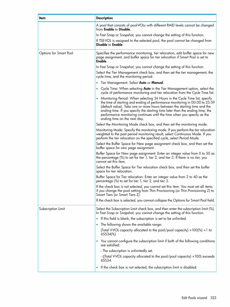
DescriptionItem
A pool that consists of pool-VOLs with different RAID levels cannot be changedfrom Enable to Disable.In Fast Snap or Snapshot, you cannot change the setting of this function.If TSE-VOL is assigned to the selected pool, the pool cannot be changed fromDisable to Enable.
Specifies the performance monitoring, tier relocation, edit buffer space for newpage assignment, and buffer space for tier relocation if Smart Pool is set toEnable.
Options for Smart Pool
In Fast Snap or Snapshot, you cannot change the setting of this function.Select the Tier Management check box, and then set the tier management, thecycle time, and the monitoring period.
• Tier Management: Select Auto or Manual.
• Cycle Time: When selecting Auto in the Tier Management option, select thecycle of performance monitoring and tier relocation from the Cycle Time list.
• Monitoring Period: When selecting 24 Hours in the Cycle Time list, specifythe time of starting and ending of performance monitoring in 00:00 to 23:59(default value). Take one or more hours between the starting time and theending time. If you specify the starting time later than the ending time, theperformance monitoring continues until the time when you specify as theending time on the next day.
Select the Monitoring Mode check box, and then set the monitoring mode.Monitoring Mode: Specify the monitoring mode. If you perform the tier relocationweighted to the past period monitoring result, select Continuous Mode. If youperform the tier relocation on the specified cycle, select Period Mode.Select the Buffer Space for New page assignment check box, and then set thebuffer space for new page assignment.Buffer Space for New page assignment: Enter an integer value from 0 to 50 asthe percentage (%) to set for tier 1, tier 2, and tier 3. If there is no tier, youcannot set this item.Select the Buffer Space for Tier relocation check box, and then set the bufferspace for tier relocation.Buffer Space for Tier relocation: Enter an integer value from 2 to 40 as thepercentage (%) to set for tier 1, tier 2, and tier 3.If the check box is not selected, you cannot set this item. You must set all itemsif you change the pool setting from Thin Provisioning (or Thin Provisioning Z) toSmart Tiers (or Smart Tiers Z).If the check box is selected, you cannot collapse the Options for Smart Pool field.
Select the Subscription Limit check box, and then enter the subscription limit (%).In Fast Snap or Snapshot, you cannot change the setting of this function.
Subscription Limit
• If this field is blank, the subscription is set to be unlimited.
• The following shows the available range:(Total V-VOL capacity allocated to the pool/pool capacity) ×100(%) +1 to65534(%)
• You cannot configure the subscription limit if both of the following conditionsare satisfied:- The subscription is unlimitedly set.- ((Total V-VOL capacity allocated to the pool/pool capacity) ×100) exceeds65534.
• If the check box is not selected, the subscription limit is disabled.
Edit Pools wizard 323

DescriptionItem
Select the Pool Name check box, and then enter the pool name.Pool Name• Prefix: Enter the alphanumeric characters, which are fixed characters of the
head of the pool name. The characters are case-sensitive.• Initial Number: Enter the initial number following the prefix name, which can
be entered up to 9 digits (when a pool is selected, the pool name appearsin the Prefix text box by default. When multiple pools are selected, the initialnumber from the set number to the maximum number of the digit number isautomatically set).
• You can enter up to the 32 characters including the initial number. The initialnumber should be 9 or less digits.
Examples:
• When 1 is set in the Initial Number field, number 1 to 9 is automatically givento the pool name.
• When 08 is set in the Initial Number field, number 08 to 99 is automaticallygiven to the pool name.
• When 098 is set in the Initial Number field, number 098 to 999 isautomatically given to the pool name.
Select the Warning Threshold check box, and then enter a threshold. Theminimum threshold is the pool usage rate plus 1%. The maximum threshold is100%.
Warning Threshold
For Fast Snap or Snapshot, you cannot change the setting of this function.Snapshot:Check Warning Threshold and enter a threshold.You cannot set this item if the result of the following calculation exceeds 95:(used-pool-capacity/pool-capacity) * 100 (%)
Select the Depletion Threshold check box, and then enter a threshold. Theminimum threshold is the pool usage rate plus 1%. The maximum threshold is100%.
Depletion Threshold
If you change the Fast Snap or Snapshot pool, you cannot set this item.
CAUTION: If you want to change multiple parameters for a pool two or more times, wait untilthe current task finishes, and then change the next settings. If you attempt to change settings beforethe current task finishes, only the settings in the next task will be applied, so the result might bedifferent from what you expected.If you use Thin Provisioning, Smart Tiers, Fast Snap, or Snapshot for the pool in which only one ofthe user-defined thresholds is set, the system threshold (fixed at 80%) is enabled. When the EditPools window opens on the pool to which the system threshold is enabled, the lower value of theuser-defined threshold or the system threshold is assigned to the Warning Threshold, and the othervalue is assigned to the Depletion Threshold. In this case, the text box of the assigned systemthreshold is blank. In the pool for which the system threshold is enabled, if either of the thresholdsis changed, the unchanged threshold is defined as follows:• If you change only Warning Threshold, the higher value of the user-defined threshold or the
system threshold (fixed at 80%) is defined as Depletion Threshold.• If you change only Depletion Threshold, the lower value of the user-defined threshold or the
system threshold (fixed at 80%) is defined as Warning Threshold.In this case, note that the reported SIM code number changes when the pool usage capacityexceeds the threshold. If the threshold changes once, the system threshold is not enabled again.
Edit Pools Confirm windowConfirm proposed settings, name the task, and then click Apply. The task will be added to theexecution queue.
324 Thin Provisioning and Smart Tiers GUI reference

DescriptionItem
Displays the pool name and pool ID.Pool Name (ID)
Displays the RAID level. If multiple RAID levels exist in a pool, this field indicatesthat RAID levels are mixed.
RAID Level
Displays the pool capacity.Capacity
Displays the pool type.Pool Type• For a Thin Provisioning pool, THP is displayed.
• For a Smart Tiers pool, Smart is displayed.
• For a Thin Provisioning Z pool, Mainframe THP is displayed.
• For a Smart Tiers Z pool, Mainframe Smart is displayed.
• For a Fast Snap pool, FS is displayed.
• For a Snapshot pool, SS is displayed.
Displays the hard disk drive type and RPMs. If multiple drive types or RPMs existin a pool, this field indicates Mixed. When the volume is the external volume,
Drive Type/RPM
Drive Type displays External Storage and the value of the external LDEV tierrank.
Displays the pool threshold.User-Defined Threshold (%)• Warning: Warning threshold is displayed.
• Depletion: Depletion threshold is displayed.
For a Fast Snap or Snapshot pool, a hyphen (-) is displayed for Depletion.
Displays the subscription limit.Subscription Limit (%)For Fast Snap or Snapshot pool, a hyphen (-) is displayed.
Displays the number of pool-VOLs.Number of Pool VOLs
Edit Pools wizard 325

DescriptionItem
Displays the Smart Tiers or Smart Tiers Z information.Smart Pool• Monitoring Mode: If the continuous mode is enabled, Continuous Mode is
displayed. If the period mode is enabled, Period Mode is displayed. If SmartTiers or Smart Tiers Z is disabled, a hyphen (-) is displayed.
• Tier Management: If Smart Tiers or Smart Tiers Z is enabled, Auto or Manualof performance monitoring and tier relocation is displayed. If Smart Tiers orSmart Tiers Z is disabled, a hyphen (-) is displayed.
• Cycle Time: Displays the cycle of performance monitoring and tier relocation.If Smart Tiers or Smart Tiers Z is disabled, a hyphen (-) is displayed.
• Monitoring Period: Displays the time zone of performance monitoring when24 Hours is selected in the Cycle Time list. If Smart Tiers or Smart Tiers Z isdisabled, a hyphen (-) is displayed.
Displays the information of the buffer space for new page assignment to eachtier.
Buffer Space for New pageassignment (%)
• Tier 1: If you make the Smart Tiers or Smart Tiers Z function available, thebuffer space for new page assignment to tier 1 is displayed. If you make theSmart Tiers or Smart Tiers Z function unavailable, a hyphen (-) is displayed.
• Tier 2: If you make the Smart Tiers or Smart Tiers Z function available, andtier 2 exists, the buffer space for new page assignment to tier 2 is displayed.If you make the Smart Tiers or Smart Tiers Z function unavailable, or tier 2does not exist, a hyphen (-) is displayed.
• Tier 3: If you make the Smart Tiers or Smart Tiers Z function available, andtier 3 exists, the buffer space for new page assignment to tier 3 is displayed.If you make the Smart Tiers or Smart Tiers Z function unavailable, or tier 3does not exist, a hyphen (-) is displayed.
Displays the information of the buffer space for tier relocation to each tier.Buffer Space for Tier relocation (%)• Tier 1: If you make the Smart Tiers or Smart Tiers Z function available, the
buffer space for tier relocation to tier 1 is displayed. If you make the SmartTiers or Smart Tiers Z function unavailable, a hyphen (-) is displayed.
• Tier 2: If you make the Smart Tiers or Smart Tiers Z function available, andtier 2 exists, the buffer space for tier relocation to tier 2 is displayed. If youmake the Smart Tiers or Smart Tiers Z function unavailable, or tier 2 does notexist, a hyphen (-) is displayed.
• Tier 3: If you make the Smart Tiers or Smart Tiers Z function available, andtier 3 exists, the buffer space for tier relocation to tier 3 is displayed. If youmake the Smart Tiers or Smart Tiers Z function unavailable, or tier 3 does notexist, a hyphen (-) is displayed.
326 Thin Provisioning and Smart Tiers GUI reference

Delete Pools wizard
Delete Pools window
DescriptionItem
Displays the pool name and pool ID.Pool Name (ID)
Displays the RAID level.RAID LevelIf multiple RAID levels exist in a pool, this field indicates that RAID levels aremixed.
Displays the pool capacity.Capacity
Displays the pool type.Pool Type• For a Thin Provisioning pool, THP is displayed.
• For a Smart Tiers pool, Smart is displayed.
• For a Thin Provisioning Z pool, Mainframe THP is displayed.
• For a Smart Tiers Z pool, Mainframe Smart is displayed.
• For a Fast Snap pool, FS is displayed.
• For a Snapshot pool, SS is displayed.
Displays the hard disk drive type and RPM of the pool. If multiple drive types orRPMs exist in a pool, this field indicates that drive types or RPMs are mixed.
Drive Type/RPM
When the volume is the external volume, Drive Type displays External Storageand the value of the external LDEV tier rank.
Displays the pool threshold.User-Defined Threshold (%)• Warning: Warning threshold is displayed.
• Depletion: Depletion threshold is displayed.
Delete Pools wizard 327
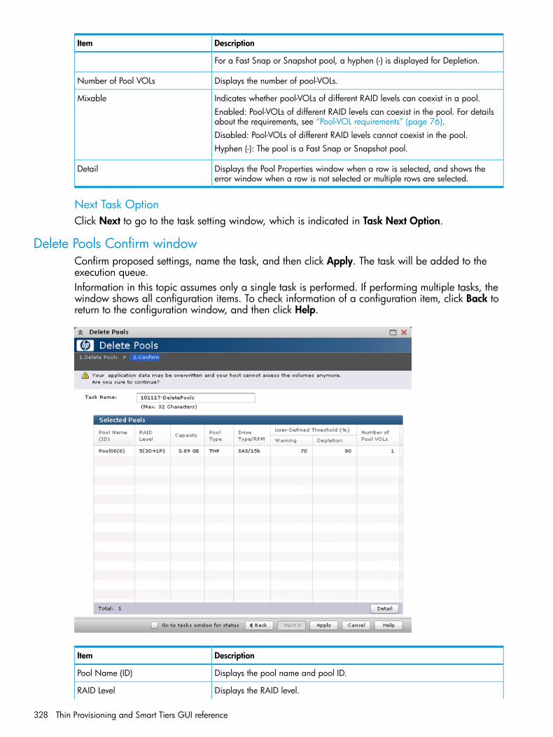
DescriptionItem
For a Fast Snap or Snapshot pool, a hyphen (-) is displayed for Depletion.
Displays the number of pool-VOLs.Number of Pool VOLs
Indicates whether pool-VOLs of different RAID levels can coexist in a pool.MixableEnabled: Pool-VOLs of different RAID levels can coexist in the pool. For detailsabout the requirements, see “Pool-VOL requirements” (page 76).Disabled: Pool-VOLs of different RAID levels cannot coexist in the pool.Hyphen (-): The pool is a Fast Snap or Snapshot pool.
Displays the Pool Properties window when a row is selected, and shows theerror window when a row is not selected or multiple rows are selected.
Detail
Next Task OptionClick Next to go to the task setting window, which is indicated in Task Next Option.
Delete Pools Confirm windowConfirm proposed settings, name the task, and then click Apply. The task will be added to theexecution queue.Information in this topic assumes only a single task is performed. If performing multiple tasks, thewindow shows all configuration items. To check information of a configuration item, click Back toreturn to the configuration window, and then click Help.
DescriptionItem
Displays the pool name and pool ID.Pool Name (ID)
Displays the RAID level.RAID Level
328 Thin Provisioning and Smart Tiers GUI reference

DescriptionItem
If multiple RAID levels exist in a pool, this field indicates that RAID levels aremixed.
Displays the pool capacity.CapacityIn the case of LUSE, shows the LUSE capacity.
Displays the pool type.Pool Type• For a Thin Provisioning pool, THP is displayed.
• For a Smart Tiers pool, Smart is displayed.
• For a Thin Provisioning Z pool, Mainframe THP is displayed.
• For a Smart Tiers Z pool, Mainframe Smart is displayed.
• For a Fast Snap pool, FS is displayed.
• For a Snapshot pool, SS is displayed.
Displays the hard disk drive type and RPM. If multiple drive types or RPMs existin a pool, this field indicates that drive types or RPMs are mixed. When the
Drive Type/RPM
volume is the external volume, Drive Type displays External Storage and thevalue of the external LDEV tier rank.
Displays the pool threshold.User-Defined Threshold (%)• Warning: Warning threshold is displayed.
• Depletion: Depletion threshold is displayed.
For a Fast Snap or Snapshot pool, a hyphen (-) is displayed for Depletion.
Displays the number of pool-VOLs.Number of Pool VOLs
Indicates whether pool-VOLs of different RAID levels can coexist in a pool.MixableEnabled: Pool-VOLs of different RAID levels can coexist in the pool. For detailsabout the requirements, see “Pool-VOL requirements” (page 76).Disabled: Pool-VOLs of different RAID levels cannot coexist in the pool.Hyphen (-): The pool is a Fast Snap or Snapshot pool.
Displays the Pool Properties window when a row is selected, and shows theerror window when a row is not selected or multiple rows are selected.
Detail
NOTE: Information in this topic assumes that only a single task is executed. If multiple tasks areexecuted, this window displays all configuration items. To check information of a configurationitem, click Back to return to each configuration window, and then click Help.
Expand V-VOLs wizard
Expand V-VOLs windowUse this wizard to expand the V-VOLs to the defined final capacity of the virtual volumes.
Expand V-VOLs wizard 329
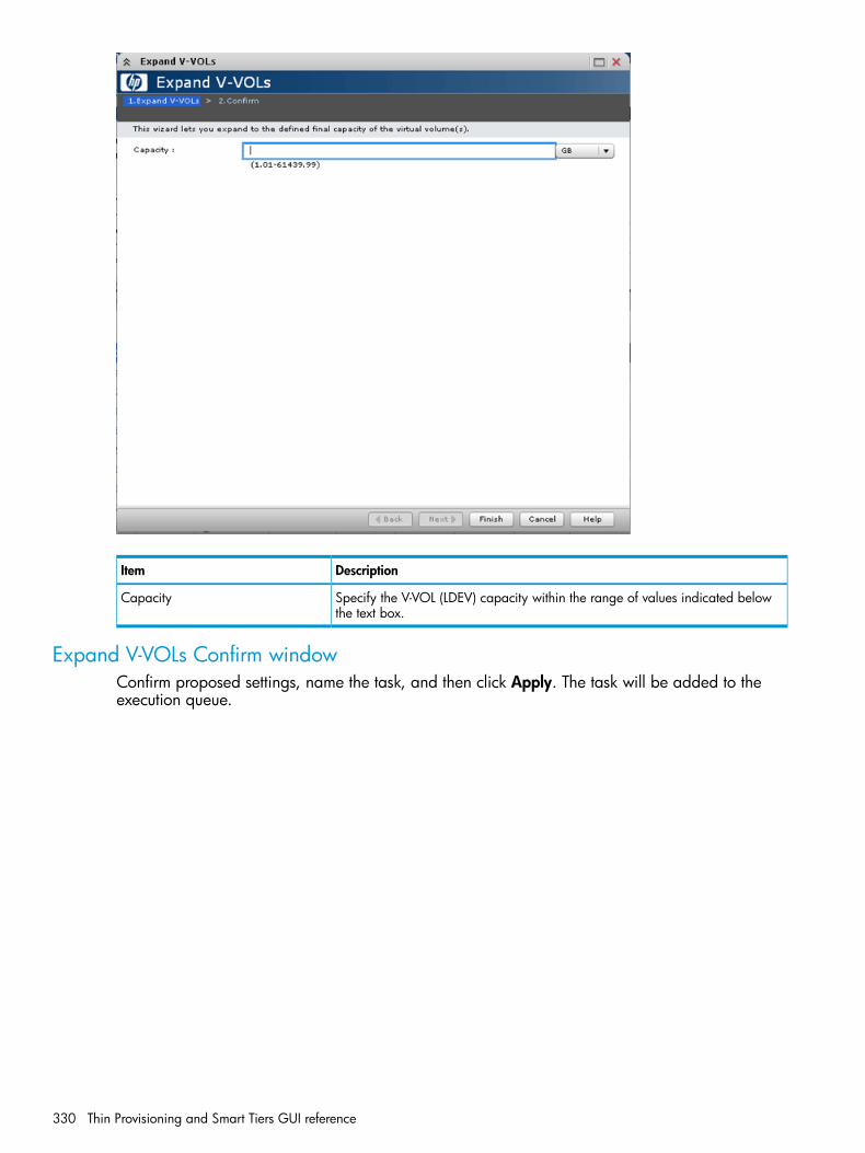
DescriptionItem
Specify the V-VOL (LDEV) capacity within the range of values indicated belowthe text box.
Capacity
Expand V-VOLs Confirm windowConfirm proposed settings, name the task, and then click Apply. The task will be added to theexecution queue.
330 Thin Provisioning and Smart Tiers GUI reference

DescriptionItem
LDEV identifier, which is the combination of LDKC, CU, and LDEV.LDEV ID
Displays the LDEV name.LDEV Name
Displays the pool name and pool ID.Pool Name (ID)
Displays the emulation type.Emulation Type
Displays the capacity of the LDEV.Capacity• Current: Displays the capacity before expanding the volume.
• Assigned: Displays the capacity that is derived by the current value subtractedfrom the final value. The value may not be exact because the size is displayedwith two decimal places.
• Final: Displays the capacity after expanding the volume.
Displays the LDEV type. In this case, THP is displayed.Provisioning Type
Displays the attribute of the LDEV.Attribute• Command Device: Command device.
• TSE: TSE-VOL.
• Hyphen (-): Volume in which the attribute is not defined.
Expand V-VOLs wizard 331

Restore Pools window
DescriptionItem
Displays the pool name and pool ID.Pool Name (ID)
Displays the RAID level.RAID LevelIf multiple RAID levels exist in a pool, this field indicates that RAID levels aremixed.
Displays the pool capacity. If the pool is blocked and pool-VOLs that belong tothe pool cannot be identified, 0 is displayed.
Capacity
Displays the pool type.Pool Type• For a Thin Provisioning pool, THP is displayed.
• For a Smart Tiers pool, Smart is displayed.
• For a Thin Provisioning Z pool, Mainframe THP is displayed.
• For a Smart Tiers Z pool, Mainframe Smart is displayed.
• For a Fast Snap pool, FS is displayed.
• For a Snapshot pool, SS is displayed.
Displays the hard disk drive type and RPM. If multiple drive types or RPMs existin a pool, this field indicates that drive types or RPMs are mixed. When the
Drive Type/RPM
volume is the external volume, Drive Type displays External Storage and thevalue of the external LDEV tier rank.
Displays the pool threshold.User-Defined Threshold (%)• Warning: Warning threshold is displayed.
• Depletion: Depletion threshold is displayed.
For a Fast Snap or Snapshot pool, a hyphen (-) is displayed for Depletion.
Displays the number of pool-VOLs.Number of Pool VOLsIf the pool is blocked and pool-VOLs that belong to the pool cannot be identified,0 is displayed.
332 Thin Provisioning and Smart Tiers GUI reference

Shrink Pool window
Prediction Result of Shrinking table
DescriptionItem
Displays the pool name and pool ID.Pool Name (ID)
Displays the pool threshold.User-Defined Threshold (%)• Warning: Warning threshold is displayed.
• Depletion: Depletion threshold is displayed.
For a Fast Snap or Snapshot pool, a hyphen (-) is displayed for Depletion.
Displays the capacity before and after shrinking.Capacity(Used/Total)• Before Shrinking: Displays the used capacity, total capacity before shrinking
and the usage rates.• After Shrinking: Displays the used capacity, total capacity after shrinking and
the usage rates.
Selected Pool Volumes table
DescriptionItem
LDEV identifier, which is the combination of LDKC, CU, and LDEV.LDEV ID
Displays the LDEV name.LDEV Name
Displays the parity group ID.Parity Group ID
Displays the emulation type.Emulation Type
Displays the pool-VOL capacity.Capacity
Shrink Pool window 333
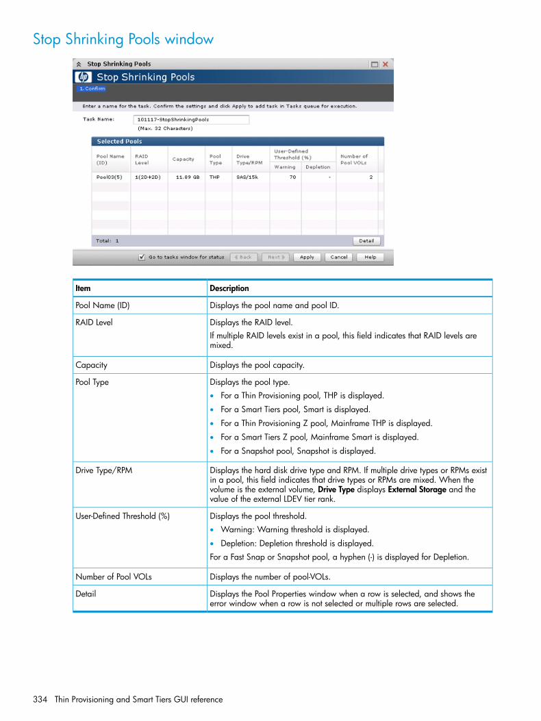
Stop Shrinking Pools window
DescriptionItem
Displays the pool name and pool ID.Pool Name (ID)
Displays the RAID level.RAID LevelIf multiple RAID levels exist in a pool, this field indicates that RAID levels aremixed.
Displays the pool capacity.Capacity
Displays the pool type.Pool Type• For a Thin Provisioning pool, THP is displayed.
• For a Smart Tiers pool, Smart is displayed.
• For a Thin Provisioning Z pool, Mainframe THP is displayed.
• For a Smart Tiers Z pool, Mainframe Smart is displayed.
• For a Snapshot pool, Snapshot is displayed.
Displays the hard disk drive type and RPM. If multiple drive types or RPMs existin a pool, this field indicates that drive types or RPMs are mixed. When the
Drive Type/RPM
volume is the external volume, Drive Type displays External Storage and thevalue of the external LDEV tier rank.
Displays the pool threshold.User-Defined Threshold (%)• Warning: Warning threshold is displayed.
• Depletion: Depletion threshold is displayed.
For a Fast Snap or Snapshot pool, a hyphen (-) is displayed for Depletion.
Displays the number of pool-VOLs.Number of Pool VOLs
Displays the Pool Properties window when a row is selected, and shows theerror window when a row is not selected or multiple rows are selected.
Detail
334 Thin Provisioning and Smart Tiers GUI reference
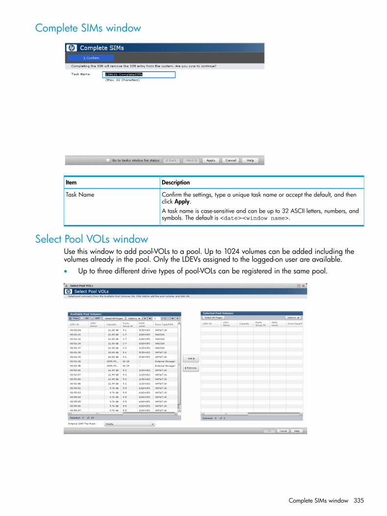
Complete SIMs window
DescriptionItem
Confirm the settings, type a unique task name or accept the default, and thenclick Apply.
Task Name
A task name is case-sensitive and can be up to 32 ASCII letters, numbers, andsymbols. The default is <date>-<window name>.
Select Pool VOLs windowUse this window to add pool-VOLs to a pool. Up to 1024 volumes can be added including thevolumes already in the pool. Only the LDEVs assigned to the logged-on user are available.• Up to three different drive types of pool-VOLs can be registered in the same pool.
Complete SIMs window 335
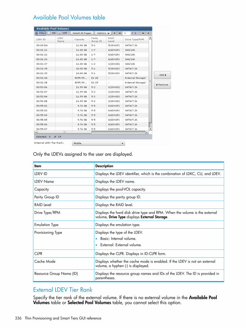
Available Pool Volumes table
Only the LDEVs assigned to the user are displayed.
DescriptionItem
Displays the LDEV identifier, which is the combination of LDKC, CU, and LDEV.LDEV ID
Displays the LDEV name.LDEV Name
Displays the pool-VOL capacity.Capacity
Displays the parity group ID.Parity Group ID
Displays the RAID level.RAID Level
Displays the hard disk drive type and RPM. When the volume is the externalvolume, Drive Type displays External Storage.
Drive Type/RPM
Displays the emulation type.Emulation Type
Displays the type of the LDEV.Provisioning Type• Basic: Internal volume.
• External: External volume.
Displays the CLPR. Displays in ID:CLPR form.CLPR
Displays whether the cache mode is enabled. If the LDEV is not an externalvolume, a hyphen (-) is displayed.
Cache Mode
Displays the resource group names and IDs of the LDEV. The ID is provided inparentheses.
Resource Group Name (ID)
External LDEV Tier RankSpecify the tier rank of the external volume. If there is no external volume in the Available PoolVolumes table or Selected Pool Volumes table, you cannot select this option.
336 Thin Provisioning and Smart Tiers GUI reference
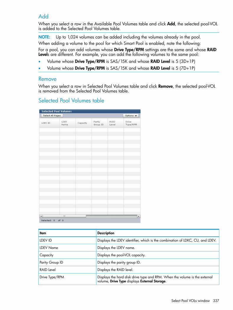
AddWhen you select a row in the Available Pool Volumes table and click Add, the selected pool-VOLis added to the Selected Pool Volumes table.
NOTE: Up to 1,024 volumes can be added including the volumes already in the pool.When adding a volume to the pool for which Smart Pool is enabled, note the following:For a pool, you can add volumes whose Drive Type/RPM settings are the same and whose RAIDLevels are different. For example, you can add the following volumes to the same pool:• Volume whose Drive Type/RPM is SAS/15K and whose RAID Level is 5 (3D+1P)• Volume whose Drive Type/RPM is SAS/15K and whose RAID Level is 5 (7D+1P)
RemoveWhen you select a row in Selected Pool Volumes table and click Remove, the selected pool-VOLis removed from the Selected Pool Volumes table.
Selected Pool Volumes table
DescriptionItem
Displays the LDEV identifier, which is the combination of LDKC, CU, and LDEV.LDEV ID
Displays the LDEV name.LDEV Name
Displays the pool-VOL capacity.Capacity
Displays the parity group ID.Parity Group ID
Displays the RAID level.RAID Level
Displays the hard disk drive type and RPM. When the volume is the externalvolume, Drive Type displays External Storage.
Drive Type/RPM
Select Pool VOLs window 337

DescriptionItem
Displays the tier rank of the external volume. If the volume is not an externalvolume, a hyphen(-) is displayed.
External LDEV Tier Rank
Displays the emulation type.Emulation Type
Displays the type of the LDEV.Provisioning Type• Basic: Internal volume.
• External: External volume.
Displays the CLPR. Displays in ID:CLPR form.CLPR
Displays whether the cache mode is enabled. If the LDEV is not an externalvolume, a hyphen (-) is displayed.
Cache Mode
Displays the resource group names and IDs of the LDEV. The ID is provided inparentheses.
Resource Group Name (ID)
Reclaim Zero Pages window
DescriptionItem
Displays the LDEV identifier, which is the combination of LDKC, CU, and LDEV.LDEV ID
Displays the LDEV name.LDEV Name
Displays the pool name and pool ID.Pool Name (ID)
Displays the emulation type.Emulation Type
Displays the capacity.Capacity
Displays the LDEV type. In this case, THP is displayed.Provisioning Type
Displays the attribute of the LDEV.Attribute• Command Device: Command device.
• Hyphen (-): Volume in which the attribute is not defined.
338 Thin Provisioning and Smart Tiers GUI reference

Stop Reclaiming Zero Pages window
DescriptionItem
Displays the LDEV identifier, which is the combination of LDKC, CU, and LDEV.LDEV ID
Displays the LDEV name.LDEV Name
Displays the pool name and pool ID.Pool Name (ID)
Displays the emulation type.Emulation Type
Displays the capacity.Capacity
Displays the LDEV type. In this case, THP is displayed.Provisioning Type
Displays the attribute of the LDEV.Attribute• Command Device: Command device.
• Hyphen (-): Volume in which the attribute is not defined.
Pool Property windowUse this window to view and change pool properties. Only the LDEVS assigned to the logged-onuser are available.
Stop Reclaiming Zero Pages window 339

Pool Properties table
DescriptionItem
Displays the pool name and pool ID.Pool Name (ID)
Displays the pool type.Pool Type• For a Thin Provisioning pool, THP is displayed.
• For a Smart Tiers pool, Smart is displayed.
• For a Thin Provisioning Z pool, Mainframe THP is displayed.
• For a Smart Tiers Z pool, Mainframe Smart is displayed.
• For a Fast Snap pool, FS is displayed.
• For a Snapshot pool, SS is displayed.
Displays the pool capacity in the specified unit.Capacity
Displays the user-defined threshold (Warning/Depletion).User-Defined Threshold(Warning/Depletion)
Displays the subscription limit.Subscription LimitFor a Fast Snap or Snapshot pool, a hyphen (-) is displayed for Current or Limit.
Displays the RAID level. If multiple RAID levels exist in a pool, this field indicatesthat RAID levels are mixed.
RAID Level
Displays the CLPR set for the Fast Snap or Snapshot pool-VOLs. Displays inID:CLPR form.
CLPR
For Pool-VOLs other than the Fast Snap or Snapshot pool-VOL, a hyphen (-) isdisplayed.
Displays LDEV ID and LDEV name of the pool-VOL which includes the systemarea. If you open this window from the Selected Pools table in the Create Poolwindow, a hyphen(-) is displayed.
Pool VOL with System Area (Name)
For a Snapshot pool, a hyphen (-) is displayed for Current or Limit.
340 Thin Provisioning and Smart Tiers GUI reference

Pool Volumes tableOnly the LDEVs assigned to the user are displayed.
DescriptionItem
Displays the LDEV identifier, which is the combination of LDKC, CU, and LDEV.LDEV ID
Displays the LDEV name.LDEV Name
Displays the pool volumes capacity in the specified unit. If you open this windowfrom the Selected Pools table in the Create Pool window, the LDEV capacityselected in the Select Pool VOLs window is displayed.
Capacity
Displays the parity group ID.Parity Group ID
Displays the RAID level.RAID Level
Displays the hard disk drive type and RPM. When the volume is the externalvolume, Drive Type displays External Storage and the value of the external LDEVtier rank.
Drive Type/RPM
Displays the emulation type.Emulation Type
Displays the type of the LDEV.Provisioning Type• Basic: Internal volume.
• External: External volume.
Displays the resource group names and IDs of the LDEV. The ID is provided inparentheses.
Resource Group Name (ID)
View Tier Properties windowThis window shows tier properties and a performance graph:• “For pools”• “For V-VOLs”When the pool name (pool ID) appears in the graph banner, you are looking a pool information.When the LDEV name (LDEV ID) appears in the graph banner, you are looking at V-VOL information.
View Tier Properties window 341

For poolsThe following table lists the View Tier Properties table information concerning pools.
DescriptionItem
Tier 1 is a high-speed hierarchy.Tier 1• Drive Type/RPM: Displays the hard disk drive type and RPM of tier 1.1
• Capacity (Used/Total): Displays the used and total capacity of tier 1.2
• Performance Utilization: Displays rate of the average used capacity whilethe performance information is being collected.3
• Buffer Space (New page assignment/Tier relocation): Displays buffer spacesfor new page assignment and tier relocation of tier 1.
Tier 2 is a middle-speed hierarchy.Tier 2• Drive Type/RPM: Displays the hard disk drive type and RPM of tier 2.1
• Capacity (Used/Total): Displays the used and total capacity of tier 2.2
• Performance Utilization: Displays rate of the average used capacity whilethe performance information is being collected.3
• Buffer Space (New page assignment/Tier relocation): Displays buffer spacesfor new page assignment and tier relocation of tier 2.
Tier 3 is a low-speed hierarchy.Tier 3• Drive Type/RPM: Displays the hard disk drive type and RPM of tier 3.1
• Capacity (Used/Total): Displays the used and total capacity of tier 3.2
342 Thin Provisioning and Smart Tiers GUI reference

DescriptionItem
• Performance Utilization: Displays rate of the average used capacity whilethe performance information is being collected.3
• Buffer Space (New page assignment/Tier relocation): Displays buffer spacesfor new page assignment and tier relocation of tier 3.
Notes:1. If multiple types exist in a tier, Mixed is displayed. When the volume is the external volume, Drive Type displays
External Storage and the value of the external LDEV tier rank.2. Capacity (Used/Total) is updated asynchronously with Performance Utilization. It is updated whenever the View
Tier Properties window is opened.3. Performance Utilization is updated when the performance monitoring information is collected. It is updated
asynchronously with Capacity (Used/Total). If ? is displayed, take actions according to the instruction shown inthe footer of the performance graph. If an error message and the countermeasure are not shown in the footer ofthe performance graph, refresh the window. If ? still appears, call HP Technical Support.
The following table describes the details of the performance graph when pool information is present.
DescriptionItem
Displays the pool name and ID.Performance Graph (poolname(pool ID))
Select the object to display a graph.Object• Entire Pool: Displays the graph of the entire pool.
• Tiering Policy: Displays the graph per tiering policy. Select the policy fromthe tiering policy.
Select the level of the tier of which is displayed in the graph. If Entire Pool isselected in the Object, this option appears dimmed. You can select All(0) orfrom Level1(1) to Level31(31).
Tiering Policy
Displays the performance graph.Performance Graph• Period Mode: The vertical scale indicates the average number of I/Os per
hour. The horizontal scale indicates the capacity.• Continuous Mode: The vertical scale indicates the average number of I/Os
per hour. The number of I/Os is calculated with the past cycle monitoringdata weighted to the current cycle monitoring data. The horizontal scaleindicates the capacity.
Displays the Tier1 range.Tier1 Range
Displays the Tier2 range.Tier2 Range
Used capacity of the each tieringpolicy
• Tier 1: Displays the used capacity of the each tiering policy in the tier 1.
• Tier 2: Displays the used capacity of the each tiering policy in the tier 2.
• Tier 3: Displays the used capacity of the each tiering policy in the tier 3
• Total: Displays the total used capacity of the each tiering policy in the tier 1,tier 2 and tier 3.
Displays the start time and end time of the performance monitoring.Footer area
When acquisition of the performance graph fails, the Warning icon isdisplayed along with an error message and solution. In the parentheses, anerror code is displayed.
View Tier Properties window 343

The following describes how to read the performance graph when it containspool information.The vertical scale of the graph indicates an average number of I/Os by each hour and the horizontalscale indicates capacity (GB) of the area where the I/Os are performed. In the screen above, thefirst dot shows approximately 1,500 I/Os on the vertical scale and 0 GB on the horizontal scale.The second dot shows approximately 1,100 I/Os and 20 GB. The third dot shows approximately1,050 I/Os and 38 GB.This indicates that 20 GB of capacity is available of over 1,100 I/Os but less than 1,500 I/Osbetween the first dot and the second dot, and 18 GB (38 GB minus 20 GB) of capacity is availableof over 1,050 I/Os but less than 1,100 I/Os between the second dot and the third dot. The I/Ocounts on a dot were processed on the capacity by subtracting the previous dot's capacity fromthe dot's capacity.The two lines in the graph indicate tier 1 range and tier 2 range. They are calculated when thecollection of performance monitoring has been completed (monitoring period is completed). Theyshow the boundary of each tier.The sample graph, above, shows 1,050 I/Os for tier 1 range, and 200 I/Os for tier 2 range.This case means the area with 1,050 or more I/Os moves to tier 1, the area with over 200 I/Osbut less than 1,050 I/Os moves to tier 2, and the area with less than 200 I/Os moves to tier 3.However, the area in the appropriate tier does not move. When the cursor is placed on a dot ofthe graph, information such as average I/O counts, capacity, and tier range appears over thedot.When no I/Os are in the lower tier with multiple tiers, the tier range line is placed at 0 on thevertical scale.For example, if the dot is placed far from the lower limit of the tier range, the lower limit levels ofthe Tier 1 Range and Tier 2 Range are adjusted to improve the visibility of the performance graph.In this case, the value that is obtained by RAID Manager may not correspond with the value of thedot displayed in a performance graph.
For V-VOLsThe following table provides the View Tier Properties table information when LDEV information ispresent.
DescriptionItem
Tier 1 is the most frequently accessed and high-speed hierarchy.Tier 1• Drive Type/RPM: The drive type and rpm of tier 1.*
• Capacity (Used): The used capacity of tier 1.
• Performance Utilization: Not available.
• Buffer Space (New page assignment/Tier relocation): Buffer spaces for newpage assignments and tier relocation of tier 1.
Tier 2 is the second frequently accessed and middle-speed hierarchy.Tier 2• Drive Type/RPM: The drive type and rpm of tier 2.*
• Capacity (Used): The used capacity of tier 2.
• Performance Utilization: Not available.
• Buffer Space (New page assignment/Tier relocation): Buffer spaces for newpage assignments and tier relocation of tier 2.
Tier 3 is the less frequently accessed and low-speed hierarchy.Tier 3• Drive Type/RPM: The drive type and rpm of tier 3.*
• Capacity (Used): The used capacity of tier 3.
344 Thin Provisioning and Smart Tiers GUI reference
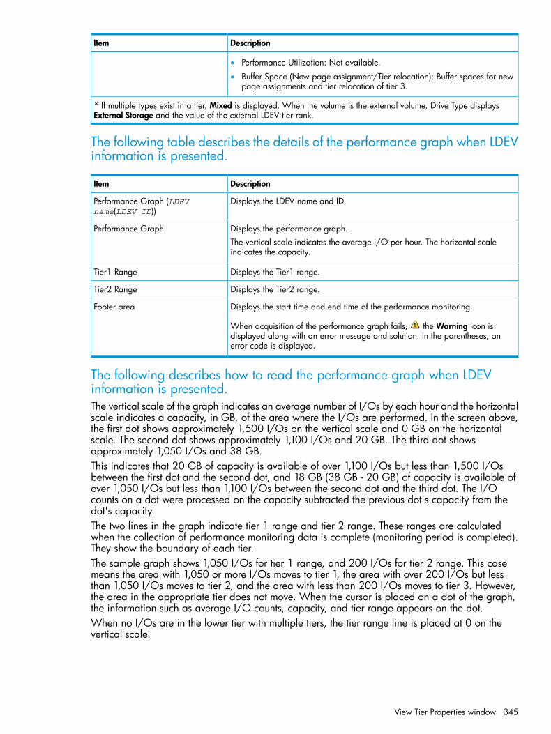
DescriptionItem
• Performance Utilization: Not available.
• Buffer Space (New page assignment/Tier relocation): Buffer spaces for newpage assignments and tier relocation of tier 3.
* If multiple types exist in a tier, Mixed is displayed. When the volume is the external volume, Drive Type displaysExternal Storage and the value of the external LDEV tier rank.
The following table describes the details of the performance graph when LDEVinformation is presented.
DescriptionItem
Displays the LDEV name and ID.Performance Graph (LDEVname(LDEV ID))
Displays the performance graph.Performance GraphThe vertical scale indicates the average I/O per hour. The horizontal scaleindicates the capacity.
Displays the Tier1 range.Tier1 Range
Displays the Tier2 range.Tier2 Range
Displays the start time and end time of the performance monitoring.Footer area
When acquisition of the performance graph fails, the Warning icon isdisplayed along with an error message and solution. In the parentheses, anerror code is displayed.
The following describes how to read the performance graph when LDEVinformation is presented.The vertical scale of the graph indicates an average number of I/Os by each hour and the horizontalscale indicates a capacity, in GB, of the area where the I/Os are performed. In the screen above,the first dot shows approximately 1,500 I/Os on the vertical scale and 0 GB on the horizontalscale. The second dot shows approximately 1,100 I/Os and 20 GB. The third dot showsapproximately 1,050 I/Os and 38 GB.This indicates that 20 GB of capacity is available of over 1,100 I/Os but less than 1,500 I/Osbetween the first dot and the second dot, and 18 GB (38 GB - 20 GB) of capacity is available ofover 1,050 I/Os but less than 1,100 I/Os between the second dot and the third dot. The I/Ocounts on a dot were processed on the capacity subtracted the previous dot's capacity from thedot's capacity.The two lines in the graph indicate tier 1 range and tier 2 range. These ranges are calculatedwhen the collection of performance monitoring data is complete (monitoring period is completed).They show the boundary of each tier.The sample graph shows 1,050 I/Os for tier 1 range, and 200 I/Os for tier 2 range. This casemeans the area with 1,050 or more I/Os moves to tier 1, the area with over 200 I/Os but lessthan 1,050 I/Os moves to tier 2, and the area with less than 200 I/Os moves to tier 3. However,the area in the appropriate tier does not move. When the cursor is placed on a dot of the graph,the information such as average I/O counts, capacity, and tier range appears on the dot.When no I/Os are in the lower tier with multiple tiers, the tier range line is placed at 0 on thevertical scale.
View Tier Properties window 345
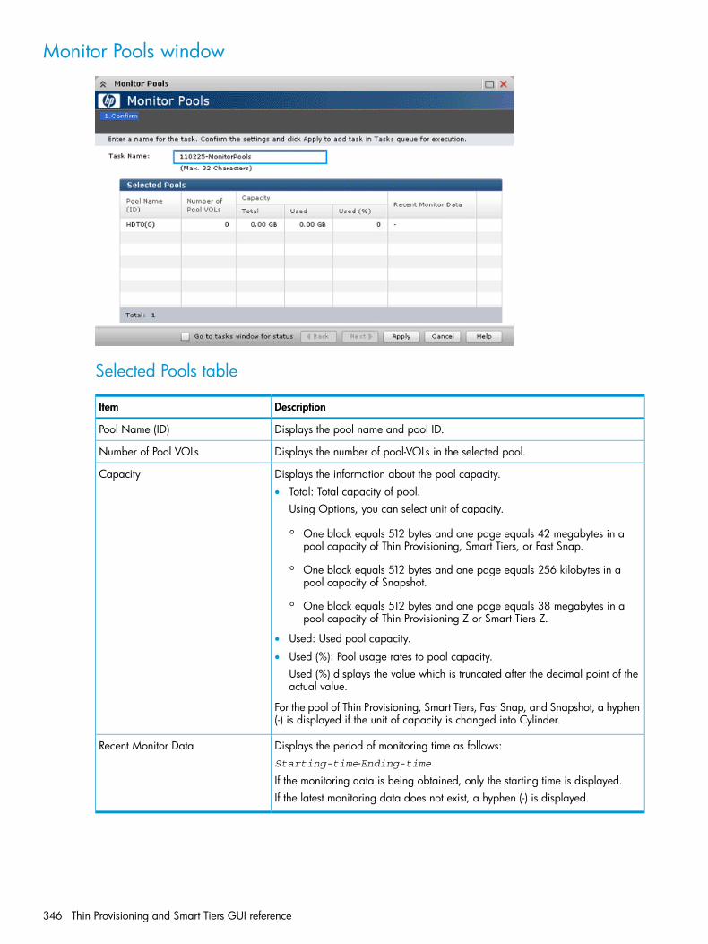
Monitor Pools window
Selected Pools table
DescriptionItem
Displays the pool name and pool ID.Pool Name (ID)
Displays the number of pool-VOLs in the selected pool.Number of Pool VOLs
Displays the information about the pool capacity.Capacity• Total: Total capacity of pool.
Using Options, you can select unit of capacity.
◦ One block equals 512 bytes and one page equals 42 megabytes in apool capacity of Thin Provisioning, Smart Tiers, or Fast Snap.
◦ One block equals 512 bytes and one page equals 256 kilobytes in apool capacity of Snapshot.
◦ One block equals 512 bytes and one page equals 38 megabytes in apool capacity of Thin Provisioning Z or Smart Tiers Z.
• Used: Used pool capacity.
• Used (%): Pool usage rates to pool capacity.Used (%) displays the value which is truncated after the decimal point of theactual value.
For the pool of Thin Provisioning, Smart Tiers, Fast Snap, and Snapshot, a hyphen(-) is displayed if the unit of capacity is changed into Cylinder.
Displays the period of monitoring time as follows:Recent Monitor DataStarting-time-Ending-timeIf the monitoring data is being obtained, only the starting time is displayed.If the latest monitoring data does not exist, a hyphen (-) is displayed.
346 Thin Provisioning and Smart Tiers GUI reference

Stop Monitoring Pools window
Selected Pools table
DescriptionItem
Displays the pool name and pool ID.Pool Name (ID)
Displays the number of pool-VOLs in the selected pool.Number of Pool VOLs
Displays the information about the pool capacity.Capacity• Total: Total capacity of pool.
Using Options, you can select unit of capacity.
◦ One block equals 512 bytes and one page equals 42 megabytes in apool capacity of Thin Provisioning, Smart Tiers, or Fast Snap.
◦ One block equals 512 bytes and one page equals 256 kilobytes in apool capacity of Snapshot.
◦ One block equals 512 bytes and one page equals 38 megabytes in apool capacity of Thin Provisioning Z or Smart Tiers Z.
• Used: Used pool capacity.
• Used (%): Pool usage rates to pool capacity.Used (%) displays the value which is truncated after the decimal point of theactual value.
For the pool of Thin Provisioning, Smart Tiers, Fast Snap, and Snapshot, a hyphen(-) is displayed if the unit of capacity is changed into Cylinder.
Displays the period of monitoring time as follows:Recent Monitor DataStarting-time-Ending-time
• If the monitoring data is being obtained, only the starting time is displayed.
• If the latest monitoring data does not exist, a hyphen (-) is displayed.
Stop Monitoring Pools window 347

Start Tier Relocation window
Selected Pools table
DescriptionItem
Displays the pool name and pool ID.Pool Name (ID)
Displays the number of pool-VOLs in the selected pool.Number of Pool VOLs
Displays the information about the pool capacity.Capacity• Total: Total capacity of pool.
Using Options, you can select unit of capacity.
◦ One block equals 512 bytes and one page equals 42 megabytes in apool capacity of Thin Provisioning, Smart Tiers, or Fast Snap.
◦ One block equals 512 bytes and one page equals 256 kilobytes in apool capacity of Snapshot.
◦ One block equals 512 bytes and one page equals 38 megabytes in apool capacity of Thin Provisioning Z or Smart Tiers Z.
• Used: Used pool capacity.
• Used (%): Pool usage rates to pool capacity.Used (%) displays the value which is truncated after the decimal point of theactual value.
For the pool of Thin Provisioning, Smart Tiers, Fast Snap, and Snapshot, a hyphen(-) is displayed if the unit of capacity is changed into Cylinder.
Displays the period of monitoring time as follows:Recent Monitor DataStarting-time-Ending-time
• If the monitoring data is being obtained, only the starting time is displayed.
• If the latest monitoring data does not exist, a hyphen (-) is displayed.
348 Thin Provisioning and Smart Tiers GUI reference
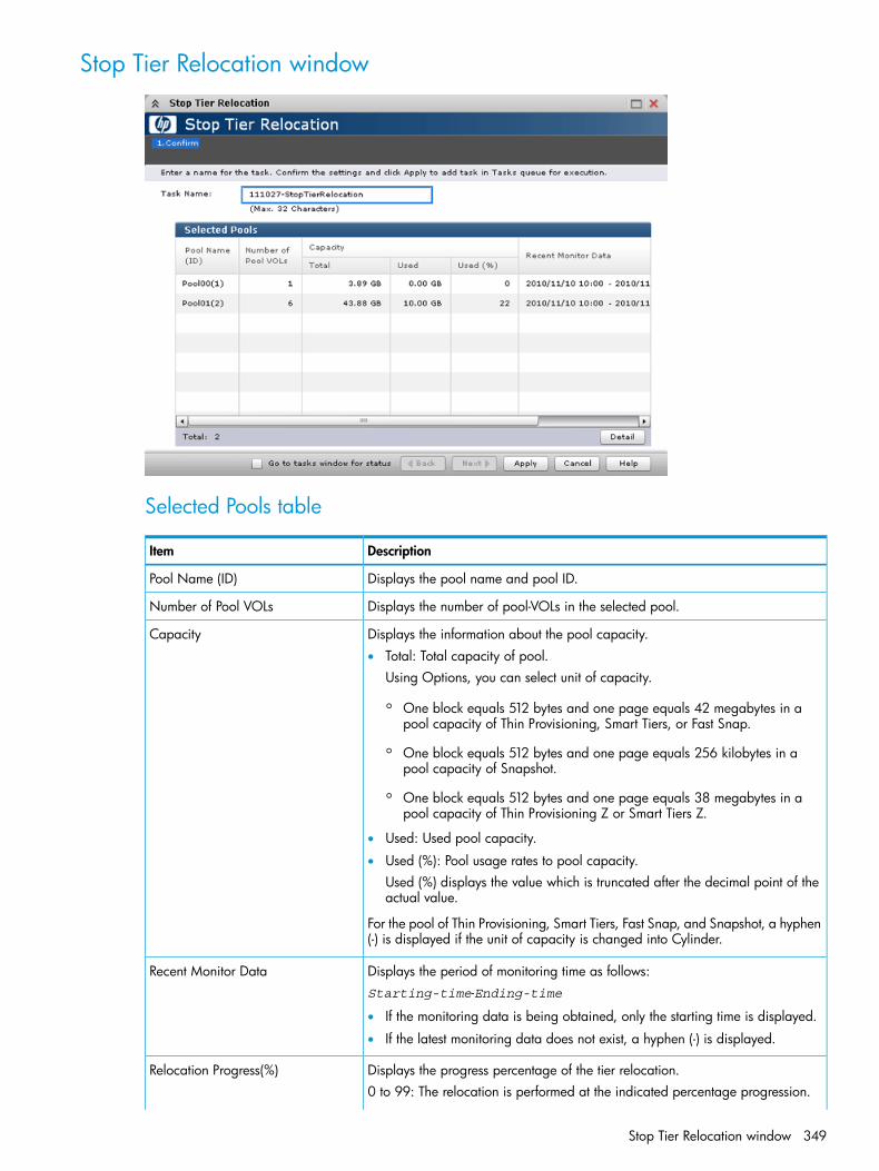
Stop Tier Relocation window
Selected Pools table
DescriptionItem
Displays the pool name and pool ID.Pool Name (ID)
Displays the number of pool-VOLs in the selected pool.Number of Pool VOLs
Displays the information about the pool capacity.Capacity• Total: Total capacity of pool.
Using Options, you can select unit of capacity.
◦ One block equals 512 bytes and one page equals 42 megabytes in apool capacity of Thin Provisioning, Smart Tiers, or Fast Snap.
◦ One block equals 512 bytes and one page equals 256 kilobytes in apool capacity of Snapshot.
◦ One block equals 512 bytes and one page equals 38 megabytes in apool capacity of Thin Provisioning Z or Smart Tiers Z.
• Used: Used pool capacity.
• Used (%): Pool usage rates to pool capacity.Used (%) displays the value which is truncated after the decimal point of theactual value.
For the pool of Thin Provisioning, Smart Tiers, Fast Snap, and Snapshot, a hyphen(-) is displayed if the unit of capacity is changed into Cylinder.
Displays the period of monitoring time as follows:Recent Monitor DataStarting-time-Ending-time
• If the monitoring data is being obtained, only the starting time is displayed.
• If the latest monitoring data does not exist, a hyphen (-) is displayed.
Displays the progress percentage of the tier relocation.Relocation Progress(%)0 to 99: The relocation is performed at the indicated percentage progression.
Stop Tier Relocation window 349

DescriptionItem
100: The relocation operation is not in performed, or the relocation is complete.For details about the tier relocation, see the tier relocation log file. For detailsabout the table items of the tier relocation log file, see “Tier relocation log filecontents” (page 107).
Displays the status of the pool tier relocation.Relocation Status• Status: Displays In Progress if the tier relocation is being performed. Displays
a hyphen(-) if the tier relocation is not performed.• Progress (%): Displays the progress ratio of the tier relocation.
0 to 99: Shows one of the following statuses.When In Progress is displayed in the Status cell: Relocation is in progress.When a hyphen (-) is displayed in the Status cell: Relocation is suspended atthe indicated percentage progression.100: Shows if the relocation operation is not in progress, or the relocationis completed.
For details about the relocation progress rate, check the tier relocation log file.
View Pool Management Status window
Pool Management Status table
DescriptionItem
Displays the pool name and pool ID.Pool Name (ID)
Displays the pool type.Pool Type• For a Thin Provisioning pool, THP is displayed.
• For a Smart Tiers pool, Smart is displayed.
• For a Thin Provisioning Z pool, Mainframe THP is displayed.
350 Thin Provisioning and Smart Tiers GUI reference

DescriptionItem
• For a Smart Tiers Z pool, Mainframe Smart is displayed.
• For a Fast Snap pool, FS is displayed.
Displays the number of V-VOLs associated with the pool, and the maximumnumber of V-VOLs that can be associated with the pool.
Number of V-VOLs
If you select a Thin Provisioning, Smart Tiers, Thin Provisioning Z, or a SmartTiers Z pool, this item appears.
Displays the number of primary volumes of Fast Snap pairs that are associatedwith the pool.
Number of Primary VOLs
If you select a Fast Snap pool, this item appears.
Displays the number of pool-VOLs set for the pool, and the maximum number ofpool-VOLs that can be set for the pool.
Number of Pool VOLs
If Smart Tiers or Smart Tiers Z is enabled, Auto or Manual of performancemonitoring and tier relocation is displayed. If Smart Tiers or Smart Tiers Z isdisabled, a hyphen (-) is displayed.
Tier Management
Displays the monitoring mode that is set for the pool. If the continuous mode isenabled, Continuous Mode is displayed. If the period mode is enabled, Period
Monitoring Mode
Mode is displayed. If Smart Tiers or Smart Tiers Z is disabled, a hyphen (-) isdisplayed.
Displays the status of pool monitoring.Monitoring StatusIf the monitoring is being performed, In Progress is displayed. A hyphen (-) isdisplayed other than this case.
Displays the status and progress ratio of the pool management task beingperformed to the pool, and average progress ratio of the each V-VOL in thepool.
Pool Management Task(Status/Progress)
• Waiting for Rebalance: The rebalance process is being waited.
• Rebalancing: The rebalance process is being performed.
• Waiting for Relocation: The tier relocation process is being waited.
• Relocating: The tier relocation process is being performed.
• Waiting for Shrink: The pool shrinking process is being waited.
• Shrinking: The pool shrinking process is being performed.
• Hyphen (-): The pool management task is not being performed to the pool.
Because the progress of the pool management task is calculated after the progressof the V-VOL management task was calculated, the following values displayedon the Virtual Volume table may not correspond with the value displayed on thisitem.
• Pool Management Task - Status
• Pool Management Task - Progress(%)
For details about the tier relocation, see the tier relocation log file. For detailsabout the table items of the tier relocation log file, see “Tier relocation log filecontents” (page 107).
Displays the status of the tier relocation processing.Relocation Result• In Progress: The status of Pool Management Task is Waiting for Relocation
or Relocating.• Completed: The tier relocation operation is not in progress, or the tier
relocation is complete.• Uncompleted (n% relocated): The tier relocation is suspended at the indicated
percentage progression.• Hyphen (-): The pool is not a Smart Tiers or Smart Tiers Z pool.
View Pool Management Status window 351

DescriptionItem
Displays the used and total pool capacity. If the pool consists of multiplepool-VOLs, the sum of its capacities is displayed in the Total field.
Capacity - Used/Total
Displays the free and formatted pool capacity. If the pool consists of multiplepool-VOLs, the sum of its capacities is displayed in the Total field.
Capacity - Free
Virtual Volume tableIf you select a Thin Provisioning, Smart Tiers, Thin Provisioning Z, or a Smart Tiers Z pool, this tableis displayed.
DescriptionItem
Displays the LDEV identifier, which is the combination of LDKC, CU, and LDEV.LDEV ID
Displays the LDEV name.LDEV Name
Displays the pool management task being performed to the pool.Pool Management Task - Status• Waiting for Rebalance: The rebalance process is being waited.
• Rebalancing: The rebalance process is being performed.
• Waiting for Relocation: The tier relocation process is being waited.
• Relocating: The tier relocation process is being performed.
• Waiting for Shrink: The pool shrinking process is being waited.
• Shrinking: The pool shrinking process is being performed.
• Hyphen (-): The pool management task is not being performed to the pool.
Displays V-VOL progress percentage (%) of the pool management task beingperformed. A hyphen (-) is displayed when the pool management task is notperformed.
Pool Management Task - Progress(%)
Displays the V-VOL management task being performed to V-VOL.V-VOL Management Task - Status• Reclaiming Zero Pages: The zero page reclaim processing that is being
performed.• Waiting for Zero Page Reclaiming: The zero page reclaim processing
• Hyphen (-): The V-VOL management task is not being performed to V-VOL.
Displays the progress percentages (%) of the V-VOL management task beingperformed. A hyphen (-) is displayed when the V-VOL management task is notperformed.
V-VOL Management Task -Progress(%)
Displays the emulation type.Emulation Type
Displays the V-VOL capacity.Capacity - Total
Displays the V-VOL used capacity.Capacity - UsedThe displayed value of Total might be larger than the displayed value of Useddue to following reasons:
• Used displays the used V-VOL capacity which is rounded up on each page.
• If the emulation type is 3390-A, the used capacity of V-VOL includes thecapacity of control cylinders (7 Cyl is required per 1,113 Cyl).
• If the emulation type is 3390-A and the TSE Attribute is set to Enable, theused capacity of V-VOL includes the management area capacity.
Displays the V-VOL usage ratio.Capacity - Used(%)
352 Thin Provisioning and Smart Tiers GUI reference

DescriptionItem
Displays the tiering policy name and ID.Tiering Policy• All(0): Policy set when all tiers in the pool are used.
• Level1(1) - Level31(31): One of the policies from Level1 to Level31 is set.
• Hyphen (-): V-VOL is not the Smart Tiers or Smart Tiers Z V-VOL.
Displays the new page assigned tier.New Page Assignment Tier• High: High is set to V-VOL.
• Middle: Middle is set to V-VOL.
• Low: Low is set to V-VOL.
• Hyphen (-): V-VOL is not the Smart Tiers or Smart Tiers Z V-VOL.
Displays whether tier relocation is set to enable or disable. If the Smart Tiers orSmart Tiers Z V-VOL is not used, a hyphen (-) is displayed.
Tier Relocation
Displays the relocation priority.Relocation Priority• Prioritized: The priority is set to V-VOL.
• Blank: The priority is not set to V-VOL.
• Hyphen (-): V-VOL is not the Smart Tiers or Smart Tiers Z V-VOL or the tierrelocation function is disabled.
Displays the attribute of the LDEV.Attribute• TSE: TSE-VOL.
• Hyphen (-): Volume in which the attribute is not defined.
View Pool Management Status window 353
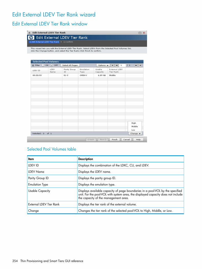
Edit External LDEV Tier Rank wizard
Edit External LDEV Tier Rank window
Selected Pool Volumes table
DescriptionItem
Displays the combination of the LDKC, CU, and LDEV.LDEV ID
Displays the LDEV name.LDEV Name
Displays the parity group ID.Parity Group ID
Displays the emulation type.Emulation Type
Displays available capacity of page boundaries in a pool-VOL by the specifiedunit. For the pool-VOL with system area, the displayed capacity does not includethe capacity of the management area.
Usable Capacity
Displays the tier rank of the external volume.External LDEV Tier Rank
Changes the tier rank of the selected pool-VOL to High, Middle, or Low.Change
354 Thin Provisioning and Smart Tiers GUI reference

Edit External LDEV Tier Rank Confirm window
Selected Pool table
DescriptionItem
Displays the pool name and pool ID.Pool Name (ID)
Selected Pool Volumes table
DescriptionItem
Displays the combination of the LDKC, CU, and LDEV.LDEV ID
Displays the LDEV name.LDEV Name
Displays the parity group ID.Parity Group ID
Displays the emulation type.Emulation Type
Displays available capacity of page boundaries in a pool-VOL by the specifiedunit. For the pool-VOL with system area, the displayed capacity does not includethe capacity of the management area.
Usable Capacity
Displays the tier rank of the external volume.External LDEV Tier Rank
Edit External LDEV Tier Rank wizard 355

Edit Tiering Policies wizard
Edit Tiering Policies window
Tiering Policies table
DescriptionItem
Displays the ID of the tiering policy.ID
Displays the name of the tiering policy.Tiering Policy
Displays the maximum percentage that is allocated to tier 1 in the total capacityto which tier relocation is performed. For a policy with an ID from 0 to 5, ahyphen (-) is displayed.
Tier1 Max(%)
Displays the minimum percentage that is allocated to tier 1 in the total capacityto which tier relocation is performed. For a policy whose ID is from 0 to 5, ahyphen (-) is displayed.
Tier1 Min(%)
Displays the maximum percentage that is allocated to tier 3 in the total capacityto which tier relocation is performed. For a policy with an ID from 0 to 5, ahyphen (-) is displayed.
Tier3 Max(%)
356 Thin Provisioning and Smart Tiers GUI reference

DescriptionItem
Displays the minimum percentage that is allocated to tier 3 in the total capacityto which tier relocation is performed. For a policy whose ID is from 0 to 5, ahyphen (-) is displayed.
Tier3 Min(%)
Displays the number of V-VOLs to which the tiering policy is set.Number of V-VOLs
Displays the Change Tiering Policy window when you select the row and clickthis button.
Change
A policy with an ID is from 0 to 5 cannot be changed.
Edit Tiering Policies Confirm window
Tiering Policies table
DescriptionItem
Displays the ID of the tiering policy.ID
Displays the name of the tiering policy.Tiering Policy
Displays the maximum percentage that is allocated to tier 1 in the total capacityto which tier relocation is performed. For a policy with an ID from 0 to 5, ahyphen (-) is displayed.
Tier1 Max(%)
Edit Tiering Policies wizard 357

DescriptionItem
Displays the minimum percentage that is allocated to tier 1 in the total capacityto which tier relocation is performed. For a policy whose ID is from 0 to 5, ahyphen (-) is displayed.
Tier1 Min(%)
Displays the maximum percentage that is allocated to tier 3 in the total capacityto which tier relocation is performed. For a policy with an ID from 0 to 5, ahyphen (-) is displayed.
Tier3 Max(%)
Displays the minimum percentage that is allocated to tier 3 in the total capacityto which tier relocation is performed. For a policy whose ID is from 0 to 5, ahyphen (-) is displayed.
Tier3 Min(%)
Displays the number of V-VOLs to which the tiering policy is set.Number of V-VOLs
Change Tiering Policy Window
Change Tiering Policy table
DescriptionItem
Displays the tiering policy name and policy ID.Tiering Policy
Select the maximum percentage that is allocated to tier 1 in the total capacityfor the tier relocation from 0 (%) to 100 (%). The setting value is needed to satisfyeither one of following conditions:
Tier1 Max(%)
• Equal to Tier1 Min
• Bigger than Tier1 Min
Select the minimum percentage that is allocated to tier 1 in the total capacityfor the tier relocation from 0 (%) to 100 (%). The setting value is needed to satisfyeither one of following conditions:
Tier1 Min(%)
• Equal to Tier1 Max
• Smaller than Tier1 Max
358 Thin Provisioning and Smart Tiers GUI reference

DescriptionItem
Select the maximum percentage that is allocated to tier 3 in the total capacityfor the tier relocation from 0 (%) to 100 (%). The setting value is needed to satisfyeither one of following conditions:
Tier3 Max(%)
• Equal to Tier1 Min
• Bigger than Tier1 Min
Select the minimum percentage that is allocated to tier 3 in the total capacityfor the tier relocation from 0 (%) to 100 (%). The setting value is needed to satisfyeither one of following conditions:
Tier3 Min(%)
• Equal to Tier1 Max
• Smaller than Tier1 Max
* The total of Tier1 Min and Tier3 Min must be 100(%) or less.
Change Tiering Policy Window 359

F Data Retention GUI referenceSections in this appendix describe the Data Retention windows, wizards, and dialog boxes usedto assign access attributes to open-system volumes.For information about common Remote Web Console operations such as using navigation buttonsand creating tasks, see the HP XP P9000 Remote Web Console User Guide.
Data Retention windowUse the Data Retention window to assign an access attribute to open-system volumes.
DescriptionItem
Select the LDKC that contains the desired CU groups.LDKC
Select the CU group that contains the desired CUs from the following:CU Group• 00-3F: CUs from 00 to 3F appear in the tree.
• 40-7F: CUs from 40 to 7F appear in the tree.
• 80-BF: CUs from 80 to BF appear in the tree.
• C0-FE: CUs from C0 to FE appear in the tree.
A list of CUs. Selecting a CU provides the selected CU information in the volume list on theright of the tree.
Tree
This tree appears only the CUs that include volumes to which access attributes can beactually set.
Lists information about the CU selected in the tree. See the table below for details.Volume list
Enables or disables enhanced volume protection.Expiration Lock• Disable -> Enable: Indicates the expiration lock is disabled. You can change an access
attribute to read/write when the retention term is over.• Enable -> Disable: Indicates the expiration lock is enabled. You cannot change an
access attribute to read/write even when the retention term is over.
360 Data Retention GUI reference

DescriptionItem
Applies settings to the storage system.Apply
Discards setting changes.Cancel
Volume listThe volume list provides information about access attributes that are assigned to volumes.If multiple volumes are combined in a LUSE volume, the top volume appears on the volume list,but the other volumes do not appear on the list. For example, if you create a LUSE volume bycombining three volumes from #03 to #05 among the volumes that belong to CU01, volume #03appears on the volume list, but volumes #04 and #05 do not appear.
DescriptionItem
The LDEV number.LDEV
• : Read/write
• : Read-only
• : Protect
The symbol beside the LDEV number indicates:
• #: an external volume
• V: a virtual volume
• X: a virtual volume used for Thin Provisioning
NOTE: If multiple volumes are combined in a LUSE volume, the Data Retention countsthese volumes as one volume. For example, if you combine five volumes into a LUSE volume,the number of these volumes is not assumed to be one but is assumed to be five.
The access attribute assigned to this volume. These attributes can be assigned using theRAID Manager (RAID Manager).
Attribute
• Read/Write: Both read and writer operations are permitted on the logical volume.
• Read-only: Read operations are permitted on the logical volume.
• Protect: Neither read nor write operations are permitted.
The volume emulation types.EmulationIf an asterisk and a number appear, the volume is a LUSE volume. For example, OPEN-3*36indicates a LUSE volume in which 36 volumes are combined.Only the top volume appears in the list. To view all the volumes, right-click the volume andselect Volume Detail.
The capacity of each volume in GB to two decimal places.Capacity
Indicates whether the volume can be specified as a secondary volume (S-VOL). You canalso use the RAID Manager to specify whether each volume can be used as an S-VOL.
S-VOL
Indicates the method that can be used to make LU path and command device settings.Reserved• Hyphen (-): Both RAID Manager and Remote Web Console can be used to make LU
path and command device settings.• RAID Manager: Only RAID Manager can be used to make LU path and command device
settings. Remote Web Console cannot be used to do so.
Data Retention window 361

DescriptionItem
The period (in days) when you are prohibited from changing access attribute to read/write.The retention term can be extended but cannot be shortened. During the retention term,you can change read-only to protect, or vice versa.
Retention Term
• 500 days. Attempts to change access attribute to read/write are prohibited in the next500 days.
• Unlimited: The retention term is extended with no limits.
• 0 days: You can change access attribute to read/write.
Caution: In Data Retention, you can increase the value for Retention Term, but cannotdecrease the value.
The number of LU paths.Path
Indicates the mode that the RAID Manager user assigns to the volume. You cannot useRemote Web Console to change modes. You must use the RAID Manager to change modes.
Mode
• Zer: Zero Read Cap mode is assigned to the volume. If the Read Capacity command(which is a SCSI command) is issued to a volume in Zero Read Cap mode, it will bereported that the capacity of the volume is zero.
• Inv: Invisible mode is assigned to the volume. If the Inquiry command (which is a SCSIcommand) is issued to a volume in Invisible mode, it will be reported that the volumedoes not exist. Therefore, the hosts will be unable to recognize the volume.
• Zer/Inv. Both Zero Read Cap mode and Invisible mode are assigned to the volume.
• Hyphen (-): No mode is assigned by RAID Manager to the volume.
The target of the operation or the name of the operation. When no operation is performed,No Operation appears.
Operation
Also shown are the volume icons and the total number of volumes with each access attribute.
Error Detail Dialog BoxIf an error occurs with the Data Retention, the Error Detail dialog box appears. The Error Detaildialog box displays error locations and error messages. For troubleshooting information relatedto the Data Retention, see (page 213).
The items and descriptions of the Error Detail dialog box follow.
DescriptionItem
Shows the location where the error occurred. If the error relates to a volume,this column displays the LDKC number, the CU number, and the LDEV number.
Location
Displays error messages. For information on solutions, see P9000 Remote WebConsole Messages.
Error Message
Closes the Error Detail dialog box.Close
362 Data Retention GUI reference

G LUN Manager GUI referenceSections in this appendix describe the LUN Manager windows, wizards, and dialog boxes usedin managing logical units.For information about common Remote Web Console operations such as using navigation buttonsand creating tasks, see the HP XP P9000 Remote Web Console User Guide.
Port/Host Groups window after selecting Ports/Host Groups
• “Summary”• “Host Groups tab”• “Hosts tab”• “Ports tab”• “Login WWNs tab”
Port/Host Groups window after selecting Ports/Host Groups 363
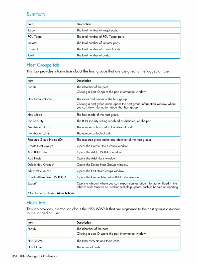
Summary
DescriptionItem
The total number of target ports.Target
The total number of RCU Target ports.RCU Target
The total number of Initiator ports.Initiator
The total number of External ports.External
The total number of ports.Total
Host Groups tabThis tab provides information about the host groups that are assigned to the logged-on user.
DescriptionItem
The identifier of the port.Port IDClicking a port ID opens the port information window.
The icons and names of the host group.Host Group NameClicking a host group name opens the host group information window whereyou can view information about that host group.
The host mode of the host group.Host Mode
The LUN security setting (enabled or disabled) on the port.Port Security
The number of hosts set to the relevant port.Number of Hosts
The number of logical units.Number of LUNs
The resource group name and identifier of the host groups.Resource Group Name (ID)
Opens the Create Host Groups window.Create Host Groups
Opens the Add LUN Paths window.Add LUN Paths
Opens the Add Hosts window.Add Hosts
Opens the Delete Host Groups window.Delete Host Groups*
Opens the Edit Host Groups window.Edit Host Groups*
Opens the Create Alternative LUN Paths window.Create Alternative LUN Paths*
Opens a window where you can export configuration information listed in thetable to a file that can be used for multiple purposes, such as backup or reporting.
Export*
*Available by clicking More Actions.
Hosts tabThis tab provides information about the HBA WWNs that are registered to the host groups assignedto the logged-on user.
DescriptionItem
The identifier of the port.Port IDClicking a port ID opens the port information window.
The HBA WWNs and their icons.HBA WWN
The name of hosts.Host Name
364 LUN Manager GUI reference

DescriptionItem
The name of the host group.Host Group Name
Opens the Add to Host Groups window.Add to Host Groups
Opens the Edit Host window.Edit Host
Opens the Remove Hosts window.Remove Hosts
Opens a window where you can export configuration information listed in thetable to a file that can be used for multiple purposes, such as backup or reporting.
Export
Ports tabThis tab provides information about the ports assigned to the logged-on user.
DescriptionItem
The Identifier of the port. Clicking a port ID opens the port information window.Port ID
The WWN of the port.Internal WWN
The data transfer speed for the selected fibre channel port in the unit of Gbps(Gigabit per second).
Speed
Valid speeds are 1, 2, 4, or 8, or 10 Gbps. If Auto is set for the port speed,Auto (actual transfer speed) appears.
The LUN security setting (enable or disable) on the port.Security
The type of the port.Type
The address of the port.Address (Loop ID)
The indicates whether a fabric switch is used.Fabric
The topology of the port.Connection Type
The attribute of the port indicating I/O flow.Attribute• Initiator: Issues I/O commands to a target port when I/O is executed between
storage systems with Continuous Access Synchronous, and so on.• Target: Receives I/O commands from a host.
• RCU Target: Receives I/O commands from an initiator when I/O is executedbetween storage systems with Continuous Access Synchronous, and so on.
• External: Issues I/O commands to a target port of an external storage systemwith External Storage.
The resource group names and IDS of the portsResource Group Name (ID)
The static MAC address assigned by the FCoE controller.ENode MAC address*
The unique identifier of the VLAN.VLAN ID*
The dynamic MAC address assigned by the FCoE switch.FPMA*
The management number of the FCoE switch.VP Index*
The status of the virtual portsVP Status*• Link Down
• Link Up (Logged In)
• Link UP (Logged Out)
Opens the Edit Ports window.Edit Ports
Port/Host Groups window after selecting Ports/Host Groups 365

DescriptionItem
Opens a window where you can export configuration information listed in thetable to a file that can be used for multiple purposes, such as backup or reporting.
Export
*This item does not appear in the window by default. To show this item in the window, change the display settings inthe Column Settings window for the table option. For details, see the HP XP P9000 Remote Web Console User Guide.
Login WWNs tab
DescriptionItem
The identifier of the port.Port IDClicking a port ID opens the port information window.
The HBA WWNs and their icons.HBA WWN
The name of the host.Host Name
The name of the host group.Host Group Name
Opens the Add to Host Groups window.Add to Host Groups
Opens the Delete Login WWNs window.Delete Login WWNs
Opens the View Login WWN Status window.View Login WWN Status
Opens a window where you can export configuration information listed in thetable to a file that can be used for multiple purposes, such as backup or reporting.
Export
366 LUN Manager GUI reference
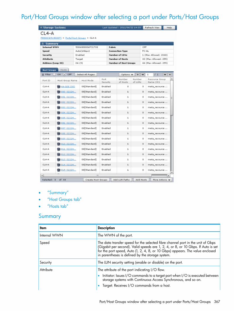
Port/Host Groups window after selecting a port under Ports/Host Groups
• “Summary”• “Host Groups tab”• “Hosts tab”
Summary
DescriptionItem
The WWN of the port.Internal WWN
The data transfer speed for the selected fibre channel port in the unit of Gbps(Gigabit per second). Valid speeds are 1, 2, 4, or 8, or 10 Gbps. If Auto is set
Speed
for the port speed, Auto (1, 2, 4, 8, or 10 Gbps) appears. The value enclosedin parentheses is defined by the storage system.
The LUN security setting (enable or disable) on the port.Security
The attribute of the port indicating I/O flow.Attribute• Initiator: Issues I/O commands to a target port when I/O is executed between
storage systems with Continuous Access Synchronous, and so on.• Target: Receives I/O commands from a host.
Port/Host Groups window after selecting a port under Ports/Host Groups 367
DescriptionItem
• RCU Target: Receives I/O commands from an initiator when I/O is executedbetween storage systems with Continuous Access Synchronous, and so on.
• External: Issues I/O commands to a target port of an external storage systemwith External Storage.
The address of the selected port.Address (Loop ID)
The indicates whether a fabric switch is used.Fabric
The topology of the selected port.Connection Type
The total number of logical units set to the relevant port, and the maximum numberof logical units that can be registered to the port. When an initiator port orexternal port is selected, a hyphen (-) appears.
Number of LUNs
The total number of hosts set to the relevant port, and the maximum number ofhosts that can be registered to the port. When an initiator port or external portis selected, a hyphen (-) appears.
Number of Hosts
The total number of host groups set to the relevant port, and the maximum numberof host groups that can be registered to the port. When an initiator port orexternal port is selected, the maximum number is not available.
Number of Host Groups
Host Groups tabThis tab provides information about the host groups assigned to the logged-on user.
CAUTION: For the initiator port, only host group 0(zero) is displayed to enable you to set a hostmode option. For details about host mode options, see “Host mode options” (page 179).
DescriptionItem
The identifier of the port.Port ID
The icons and names of host groups.Host Group NameClicking a host group name opens the host group information window.
The host mode of the host group.Host Mode
The LUN security setting (enable or disable) on the port.Port Security
The number of hosts in the host group.Number of Hosts
The number of logical units in the host group.Number of LUNs
The resource group name and ID of the host group. If the port is the initiatorport, a hyphen (-) is displayed.
Resource Group Name (ID)
Opens the Create Host Groups window.Create Host Groups
Opens the Add LUN Paths window.Add LUN Paths
Opens the Add Hosts window.Add Hosts
Opens the Delete Host Groups window.Delete Host Groups*
Opens the Edit Host Groups window.Edit Host Groups*
Opens the Create Alternative LUN Paths window.Create Alternative LUN Paths*
Opens a window where you can export configuration information listed in thetable to a file that can be used for multiple purposes, such as backup or reporting.
Export*
*Available by clicking More Actions.
368 LUN Manager GUI reference

Hosts tabThis tab provides information about the HBA WWNs that are registered to the host groups assignedto the logged-on user.
DescriptionItem
The identifier of the port.Port ID
The HBA WWNs and their icons.HBA WWN
The name of the host.Host Name
The name of the host group.Host Group Name
Opens the Add to Host Groups window.Add to Host Groups
Opens the Edit Host window.Edit Host
Opens the Remove Hosts window.Remove Hosts
Opens a window where you can export configuration information listed in thetable to a file that can be used for multiple purposes, such as backup or reporting.
Export
Port/Host Groups window after selecting a port under Ports/Host Groups 369

Port/Hosts window when selecting a host group under the port of Ports/HostGroups
• “Summary”• “Hosts tab”• “LUNs tab”• “Host Mode Options tab”
Summary
DescriptionItem
The name of the host group.Host Group Name
The identifier of the port.Port ID
The host mode of the host group.Host Mode
The LUN security setting (enable or disable) on the port.Port Security
370 LUN Manager GUI reference

Hosts tab
DescriptionItem
The identifier of the port.Port ID
The HBA WWNs and their icons.HBA WWN
The name of the host.Host Name
The name of the host group.Host Group Name
Opens the Add to Host Groups window.Add to Host Groups
Opens the Edit Host window.Edit Host
Opens the Add Hosts windowAdd Hosts
Opens the Remove Hosts window.Remove Hosts*
Opens the Add Hosts window.Add Hosts
Opens a window where you can export configuration information listed in thetable to a file that can be used for multiple purposes, such as backup or reporting.
Export
Available by clicking More Actions.
LUNs tabThis tab provides information about the LU paths that correspond to the LDEV assigned to thelogged-in user.
DescriptionItem
The identifier of the port.Port ID
The icons and identifiers of the logical unit. Clicking a LUN ID opens the LUNProperties window.
LUN ID
The LDEV identifier, which is the combination of LDKC, CU, and LDEV.LDEV IDClicking an LDEV ID takes you to the LDEV Properties window.
The name of each LDEV.LDEV Name
Displays the pool name and pool ID. If the logical volume is not the volume otherthan V-VOL, a hyphen (-) is displayed.
Pool Name (ID)
The emulation types for each logical volume (or logical device). For LUSE volumes,an asterisk (*) and a number appear on the right of the emulation type. Forexample, OPEN-9*3 indicates that three OPEN-9 volumes are combined.
Emulation Type
Displays the logical volume capacity.Capacity - Total
Displays the V-VOL used capacity.Capacity - UsedThe Total value displayed might be larger than the Used value due to followingreasons:
• Used displays the used capacity of the V-VOL that is rounded up on eachpage.
• If the emulation type is 3390-A, the used capacity of V-VOL includes thecapacity of the control cylinders (7 Cyl is required per 1,113 Cyl).
If the logical volume is not the volume other than V-VOL, a hyphen (-) is displayed.
Displays the V-VOL usage level. If the logical volume is not the volume other thanV-VOL, a hyphen (-) is displayed.
Capacity - Used(%)
Displays the used capacity of tier 1. If the logical volume is not the volume otherthan V-VOL, a hyphen (-) is displayed.
Capacity - Tier1
Port/Hosts window when selecting a host group under the port of Ports/Host Groups 371

DescriptionItem
Displays the used capacity of tier 2. If the logical volume is not the volume otherthan V-VOL, or if tier 2 does not exist, a hyphen (-) is displayed.
Capacity - Tier2
Displays the used capacity of tier 3. If the logical volume is not the volume otherthan V-VOL, or if tier 3 does not exist, a hyphen (-) is displayed.
Capacity - Tier3
Displays the type for each logical volume.Provisioning Type• Basic: Internal volume.
• External: External volume.
• THP: V-VOL of Thin Provisioning.
• Snapshot: Fast Snap volume or Snapshot volume.
The cache logical partition number, displayed as ID:CLPR.CLPR
Displays the tiering policy name and ID.Tiering PolicyAll(0): Policy specified when all tiers in the pool are used.Level1(1) to Level31(31): Policy selected from Level1 to Level31, set to the V-VOL.-: The logical volume is not the Smart Tiers or Smart Tiers Z V-VOL.
Displays the new page assignment tier of the tiering policy. See “New pageassignment tier” (page 115).
New Page Assignment Tier
-: The logical volume is not the Smart Tiers or Smart Tiers Z V-VOL.
Displays whether tier relocation is set to Enable or Disable. If the logical volumeis not to the V-VOL of Smart Tiers or Smart Tiers Z, a hyphen (-) is displayed.
Tier Relocation
Displays the attribute of the LDEV.Attribute• Command Device: Command device.
• Remote Command Device: Remote command device.
• Online Data Migration: Volume for online data migration.
• -: Volume in which the attribute is not defined.
Displays the access attribute of the LDEV.Access Attribute1
Displays the total number of relevant paths and alternative paths.Number of Paths
Opens the Add LUN Paths window.Add LUN Paths
Opens the Copy LUN Path window.Copy LUN Paths
Opens the Edit Command Devices window.Edit Command Devices
Displays the Host-Reserved LUNs window.View Host-Reserved LUNs2
Opens the Delete LUN Paths window.Delete LUN Paths2
Opens the Edit UUIDs window.Edit UUIDs2
Opens a window where you can export configuration information listed in thetable to a file that can be used for multiple purposes, such as backup or reporting.
Export2
1Does not appear by default. To display this item, change the Column Settings of the table option. For details aboutthe Column Settings window, see the HP P9000 Remote Web Console User Guide.2Appears when you click More Actions.
372 LUN Manager GUI reference
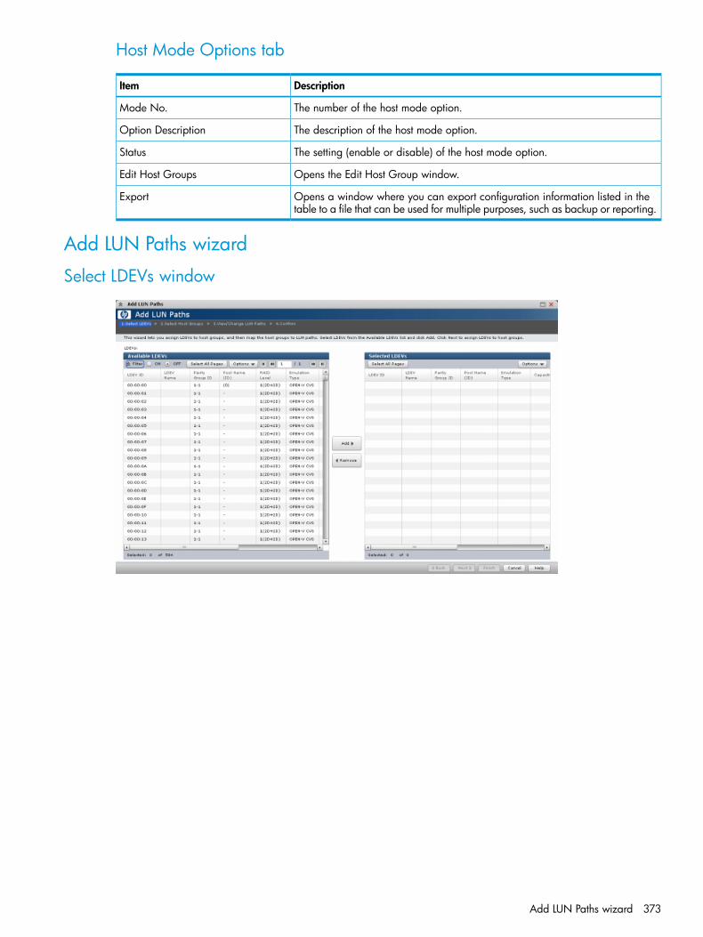
Host Mode Options tab
DescriptionItem
The number of the host mode option.Mode No.
The description of the host mode option.Option Description
The setting (enable or disable) of the host mode option.Status
Opens the Edit Host Group window.Edit Host Groups
Opens a window where you can export configuration information listed in thetable to a file that can be used for multiple purposes, such as backup or reporting.
Export
Add LUN Paths wizard
Select LDEVs window
Add LUN Paths wizard 373
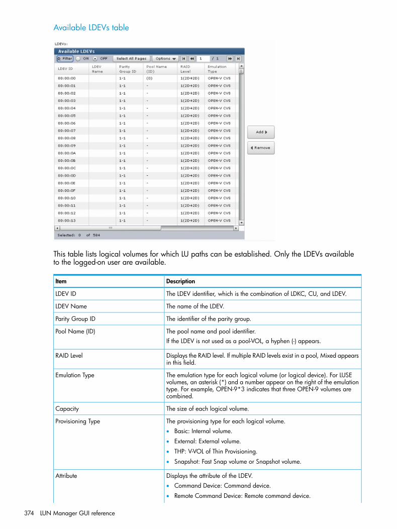
Available LDEVs table
This table lists logical volumes for which LU paths can be established. Only the LDEVs availableto the logged-on user are available.
DescriptionItem
The LDEV identifier, which is the combination of LDKC, CU, and LDEV.LDEV ID
The name of the LDEV.LDEV Name
The identifier of the parity group.Parity Group ID
The pool name and pool identifier.Pool Name (ID)If the LDEV is not used as a pool-VOL, a hyphen (-) appears.
Displays the RAID level. If multiple RAID levels exist in a pool, Mixed appearsin this field.
RAID Level
The emulation type for each logical volume (or logical device). For LUSEvolumes, an asterisk (*) and a number appear on the right of the emulation
Emulation Type
type. For example, OPEN-9*3 indicates that three OPEN-9 volumes arecombined.
The size of each logical volume.Capacity
The provisioning type for each logical volume.Provisioning Type• Basic: Internal volume.
• External: External volume.
• THP: V-VOL of Thin Provisioning.
• Snapshot: Fast Snap volume or Snapshot volume.
Displays the attribute of the LDEV.Attribute• Command Device: Command device.
• Remote Command Device: Remote command device.
374 LUN Manager GUI reference

DescriptionItem
• Online Data Migration: Volume for online data migration.
• -: Volume in which the attribute is not defined.
The number of paths set for the LDEV.Number of Paths
The resource group name and identifier of the LDEV.Resource Group Name (ID)
Adds logical volumes selected from the Available LDEVs table to the SelectedLDEVs table.
Add
Removes logical volumes from the Selected LDEVs table.Remove
Selected LDEVs table
DescriptionItem
The LDEV identifier, which is the combination of LDKC, CU, and LDEV.LDEV ID
The name of the LDEV.LDEV Name
The identifier of the parity group.Parity Group ID
The pool name and pool identifier.Pool Name (ID)If the LDEV is not used as a pool-VOL, a hyphen (-) appears.
The emulation type for each logical volume (or logical device). For LUSEvolumes, an asterisk (*) and a number appear on the right of the emulation
Emulation Type
Add LUN Paths wizard 375

DescriptionItem
type. For example, OPEN-9*3 indicates that three OPEN-9 volumes arecombined.
The size of each logical volume.Capacity
The provisioning type for each logical volume.Provisioning Type• Basic: Internal volume.
• External: External volume.
• THP: V-VOL of Thin Provisioning.
• Snapshot: Fast Snap volume or Snapshot volume.
The displays the attribute of the LDEV.Attribute• Command Device: Command device.
• Remote Command Device: Remote command device.
• Online Data Migration: Volume for online data migration.
• -: Volume in which the attribute is not defined.
The number of paths set for the LDEV.Number of Paths
The resource group name and identifier of the LDEV.Resource Group Name (ID)
Select Host Groups window
376 LUN Manager GUI reference
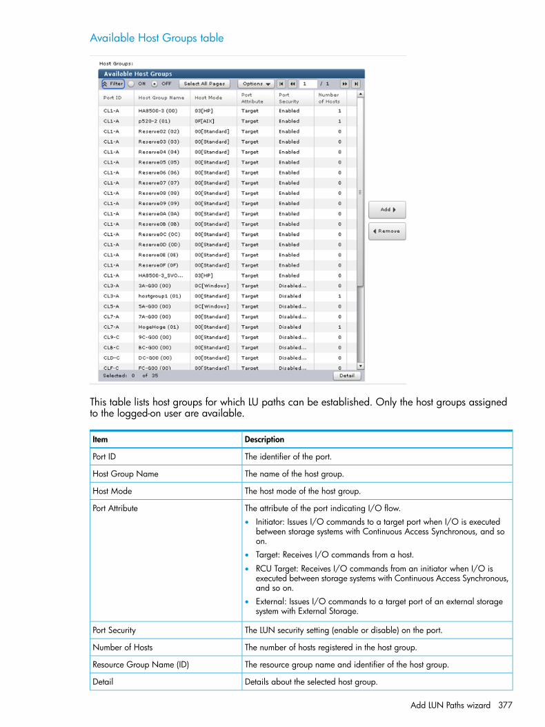
Available Host Groups table
This table lists host groups for which LU paths can be established. Only the host groups assignedto the logged-on user are available.
DescriptionItem
The identifier of the port.Port ID
The name of the host group.Host Group Name
The host mode of the host group.Host Mode
The attribute of the port indicating I/O flow.Port Attribute• Initiator: Issues I/O commands to a target port when I/O is executed
between storage systems with Continuous Access Synchronous, and soon.
• Target: Receives I/O commands from a host.
• RCU Target: Receives I/O commands from an initiator when I/O isexecuted between storage systems with Continuous Access Synchronous,and so on.
• External: Issues I/O commands to a target port of an external storagesystem with External Storage.
The LUN security setting (enable or disable) on the port.Port Security
The number of hosts registered in the host group.Number of Hosts
The resource group name and identifier of the host group.Resource Group Name (ID)
Details about the selected host group.Detail
Add LUN Paths wizard 377

DescriptionItem
Adds host groups selected from the Available Host Groups table to theSelected Host Groups table.
Add
Removes the selected host groups from the Selected Host Groups table.Remove
Selected Host Groups table
DescriptionItem
The identifier of the port.Port ID
The name of the host group.Host Group Name
The host mode of the host group.Host Mode
The attribute of the port indicating I/O flow.Port Attribute• Initiator: Issues I/O commands to a target port when I/O is executed
between storage systems with Continuous Access Synchronous, and soon.
• Target: Receives I/O commands from a host.
• RCU Target: Receives I/O commands from an initiator when I/O isexecuted between storage systems with Continuous Access Synchronous,and so on.
• External: Issues I/O commands to a target port of an external storagesystem with External Storage.
The LUN security setting (enable or disable) on the port.Port Security
378 LUN Manager GUI reference
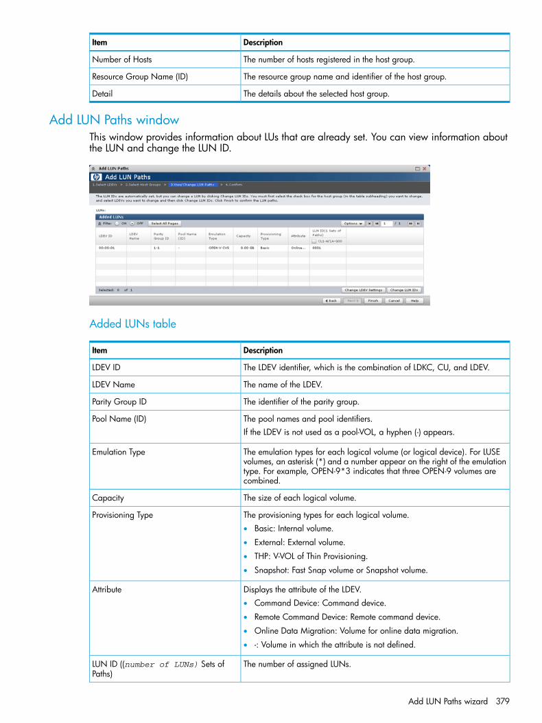
DescriptionItem
The number of hosts registered in the host group.Number of Hosts
The resource group name and identifier of the host group.Resource Group Name (ID)
The details about the selected host group.Detail
Add LUN Paths windowThis window provides information about LUs that are already set. You can view information aboutthe LUN and change the LUN ID.
Added LUNs table
DescriptionItem
The LDEV identifier, which is the combination of LDKC, CU, and LDEV.LDEV ID
The name of the LDEV.LDEV Name
The identifier of the parity group.Parity Group ID
The pool names and pool identifiers.Pool Name (ID)If the LDEV is not used as a pool-VOL, a hyphen (-) appears.
The emulation types for each logical volume (or logical device). For LUSEvolumes, an asterisk (*) and a number appear on the right of the emulation
Emulation Type
type. For example, OPEN-9*3 indicates that three OPEN-9 volumes arecombined.
The size of each logical volume.Capacity
The provisioning types for each logical volume.Provisioning Type• Basic: Internal volume.
• External: External volume.
• THP: V-VOL of Thin Provisioning.
• Snapshot: Fast Snap volume or Snapshot volume.
Displays the attribute of the LDEV.Attribute• Command Device: Command device.
• Remote Command Device: Remote command device.
• Online Data Migration: Volume for online data migration.
• -: Volume in which the attribute is not defined.
The number of assigned LUNs.LUN ID ((number of LUNs) Sets ofPaths)
Add LUN Paths wizard 379

DescriptionItem
The name of the port and the host group of assigned LUNs. This itemappears according to the number of assigned LUNs.
port ID/ host group name
To change the LDEV name setting, select an LDEV and then click this button.Change LDEV Settings
To change the LUN setting, select the check box in the table column of portID/host group name, select the target LDEV, and then click this button.
Change LUN IDs
Add LUN Paths Confirm windowConfirm proposed settings, name the task, and then click Apply. The task will be added to theexecution queue.
Added LUNs table
DescriptionItem
The identifier of the LDEV.LDEV ID
The name of the LDEV.LDEV Name
The identifier of the parity group.Parity Group ID
The pool names and pool identifiers.Pool Name (ID)If the LDEV is not used as a pool-VOL, a hyphen (-) appears.
The emulation types for each logical volume (or logical device). For LUSEvolumes, an asterisk (*) and a number appear on the right of the emulation
Emulation Type
type. For example, OPEN-9*3 indicates that three OPEN-9 volumes arecombined.
The size of each logical volume.Capacity
The provisioning types for each logical volume.Provisioning Type• Basic: Internal volume.
• External: External volume.
• THP: V-VOL of Thin Provisioning.
• Snapshot: Fast Snap volume or Snapshot volume.
Displays the attribute of the LDEV.Attribute• Command Device: Command device.
• Remote Command Device: Remote command device.
380 LUN Manager GUI reference

DescriptionItem
• Online Data Migration: Volume for online data migration.
• -: Volume in which the attribute is not defined.
The number of assigned LUNs for the relevant LDEV.LUN ID ((number of LUNs) Sets ofPaths)
The name of the port and the host group of the assigned LUNs. AssignedLUN IDs also appear.
port ID/ host group name
Create Host Groups wizard
Create Host Groups window
DescriptionItem
Enter the name of the host group.Host Group NameAs a host group name, you can use single-byte ASCII characters(alphanumeric characters and symbols) up to 64 characters. You cannotuse the following symbols: \ / : , ; * ? " < > |You cannot use blanks at the beginning or end of the host group name.
Select the resource group in which the host group is created. If Any isselected, among all ports being allocated to the user, ports where the host
Resource Group Name (ID)
group can be add are available in the Available Ports table. If other thanAny is selected, among ports assigned to the selected resource group, portswhere the host group can be add are available in the Available Ports table.
Select the host mode from the list.Host Mode
Adds the settings to the Selected Host Groups table.Add
Create Host Groups wizard 381

Available Hosts table
This table lists information about the registered hosts.
DescriptionItem
The identifier of the port.Port ID
The WWN of the port.HBA WWN
The name of the host.Host Name
The name of the host group.Host Group Name
Indicates whether this is a new host.New Host• Yes: The host is newly added and has never been connected via a cable
to any port in the storage system.• No: The host has been connected via a cable to another port.
The LUN security setting (enable or disable) on the port.Port Security
Adds a new host. Or, select host bus adapters and then click this button toassign a nickname to the host bus adapter.
Add New Host
382 LUN Manager GUI reference

Available Ports tableThis table lists the registered ports.
DescriptionItem
The identifier of the port.Port ID
The attribute of the port indicating I/O flow.Attribute• Initiator: Issues I/O commands to a target port when I/O is executed
between storage systems with Continuous Access Synchronous, and soon.
• Target: Receives I/O commands from a host.
• RCU Target: Receives I/O commands from an initiator when I/O isexecuted between storage systems with Continuous Access Synchronous,and so on.
• External: Issues I/O commands to a target port of an external storagesystem with External Storage.
The LUN security setting (enable or disable) on the port.Security
Click to view a list of host mode options.Options
Host Mode Options table
DescriptionItem
The ID number of the host mode option.Mode No.
The description of host mode option.Option Description
The setting status (enable or disable) of the host mode option.Status
Indicates that the host mode option is enabled.Enabled
Indicates that the host mode option is disabled.Disabled
Create Host Groups wizard 383
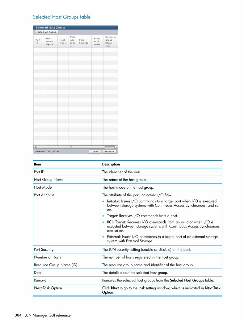
Selected Host Groups table
DescriptionItem
The identifier of the port.Port ID
The name of the host group.Host Group Name
The host mode of the host group.Host Mode
The attribute of the port indicating I/O flow.Port Attribute• Initiator: Issues I/O commands to a target port when I/O is executed
between storage systems with Continuous Access Synchronous, and soon.
• Target: Receives I/O commands from a host.
• RCU Target: Receives I/O commands from an initiator when I/O isexecuted between storage systems with Continuous Access Synchronous,and so on.
• External: Issues I/O commands to a target port of an external storagesystem with External Storage.
The LUN security setting (enable or disable) on the port.Port Security
The number of hosts registered in the host group.Number of Hosts
The resource group name and identifier of the host group.Resource Group Name (ID)
The details about the selected host group.Detail
Removes the selected host groups from the Selected Host Groups table.Remove
Click Next to go to the task setting window, which is indicated in Next TaskOption.
Next Task Option
384 LUN Manager GUI reference

Create Host Groups Confirm windowConfirm proposed settings, name the task, and then click Apply. The task will be added to theexecution queue.Information in this topic assumes only a single task is executed. If multiple tasks are executed, thewindow shows all configuration items. To check information of a configuration item, click Back toreturn to the configuration window, and then click Help.
Create Host Groups table
DescriptionItem
The identifier of the port.Port ID
The name of the host group.Host Group Name
The host mode of the host group.Host Mode
The attribute of the port indicating I/O flow.Port Attribute• Initiator: Issues I/O commands to a target port when I/O is executed
between storage systems with Continuous Access Synchronous, and soon.
• Target: Receives I/O commands from a host.
• RCU Target: Receives I/O commands from an initiator when I/O isexecuted between storage systems with Continuous Access Synchronous,and so on.
• External: Issues I/O commands to a target port of an external storagesystem with External Storage.
The LUN security setting (enable or disable) on the port.Port Security
The number of hosts registered in the host group.Number of Hosts
The resource group name and identifier of the host group.Resource Group Name (ID)
The details about the selected host group.Detail
Edit Host Groups wizard
Edit Host Groups windowUse this window to edit host group properties for selected host groups. Properties include hostgroup name, host mode, or host mode options.
Edit Host Groups wizard 385

When you select multiple host groups to which different host modes are defined, if the host groupassigned to an initiator port is included, you cannot finish the Edit Host Groups operation.
DescriptionItem
Specify the name of the host group.Host Group nameHost group name can be up to 64 single-byte ASCII characters(alpha-numerals and symbols).You cannot use the following symbols: \ / : , ; * ? " < > |You cannot use blanks at the beginning or end of the host group name.If a host group assigned to an initiator port is included in the specified hostgroups, this item is unavailable.
Select the host mode from the list.Host ModeIf a host group assigned to an initiator port is included in the specified hostgroups, this item is unavailable.
386 LUN Manager GUI reference

Host Mode Options tableTo set the host mode option, select a host mode option, and then click Enable. If you do not needa host mode option, select an unnecessary host mode option, and then click Disable.
DescriptionItem
The number identifier of the host mode option.Mode No.
The description of the host mode option.Option Description
Indicates the current status setting (enable or disable) of the host modeoption on this host group.
Status
Enables the host mode option.Enable
Disables the host mode option.Disable
Edit Host Groups Confirm windowConfirm proposed settings, name the task, and then click Apply. The task will be added to theexecution queue.
Edit Host Groups wizard 387

Selected Host Groups table
DescriptionItem
The identifier of the port.Port ID
The name of the host group.Host Group Name
The host mode of the host group.Host Mode
The attribute of the port indicating I/O flow.Port Attribute• Initiator: Issues I/O commands to a target port when I/O is executed
between storage systems with Continuous Access Synchronous, and soon.
• Target: Receives I/O commands from a host.
• RCU Target: Receives I/O commands from an initiator when I/O isexecuted between storage systems with Continuous Access Synchronous,and so on.
• External: Issues I/O commands to a target port of an external storagesystem with External Storage.
The LUN security setting (enable or disable) on the port.Port Security
The number of hosts registered in the host group.Number of Hosts
The details about the selected host group.Detail
Add to Host Groups wizard (when specific host is selected)
Add to Host Groups window
Available Host Groups tableThis table lists host groups in which selected hosts can be registered. Only the host groups assignedto the logged-on user are available.
388 LUN Manager GUI reference
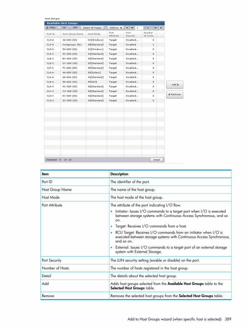
DescriptionItem
The identifier of the port.Port ID
The name of the host group.Host Group Name
The host mode of the host group.Host Mode
The attribute of the port indicating I/O flow.Port Attribute• Initiator: Issues I/O commands to a target port when I/O is executed
between storage systems with Continuous Access Synchronous, and soon.
• Target: Receives I/O commands from a host.
• RCU Target: Receives I/O commands from an initiator when I/O isexecuted between storage systems with Continuous Access Synchronous,and so on.
• External: Issues I/O commands to a target port of an external storagesystem with External Storage.
The LUN security setting (enable or disable) on the port.Port Security
The number of hosts registered in the host group.Number of Hosts
The details about the selected host group.Detail
Adds host groups selected from the Available Host Groups table to theSelected Host Groups table.
Add
Removes the selected host groups from the Selected Host Groups table.Remove
Add to Host Groups wizard (when specific host is selected) 389
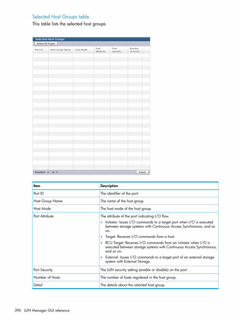
Selected Host Groups tableThis table lists the selected host groups.
DescriptionItem
The identifier of the port.Port ID
The name of the host group.Host Group Name
The host mode of the host group.Host Mode
The attribute of the port indicating I/O flow.Port Attribute• Initiator: Issues I/O commands to a target port when I/O is executed
between storage systems with Continuous Access Synchronous, and soon.
• Target: Receives I/O commands from a host.
• RCU Target: Receives I/O commands from an initiator when I/O isexecuted between storage systems with Continuous Access Synchronous,and so on.
• External: Issues I/O commands to a target port of an external storagesystem with External Storage.
The LUN security setting (enable or disable) on the port.Port Security
The number of hosts registered in the host group.Number of Hosts
The details about the selected host group.Detail
390 LUN Manager GUI reference

Add to Host Groups Confirm windowConfirm proposed settings, name the task, and then click Apply. The task will be added to theexecution queue.
Selected Hosts tableThis table lists the hosts selected to be added to a host group.
DescriptionItem
The WWN of the port.HBA WWN
The name of the host.Host Name
Selected Host Groups tableA list of host groups to which hosts are registered.
DescriptionItem
The identifier of the port.Port ID
The name of the host group.Host Group Name
Add to Host Groups wizard (when specific host is selected) 391
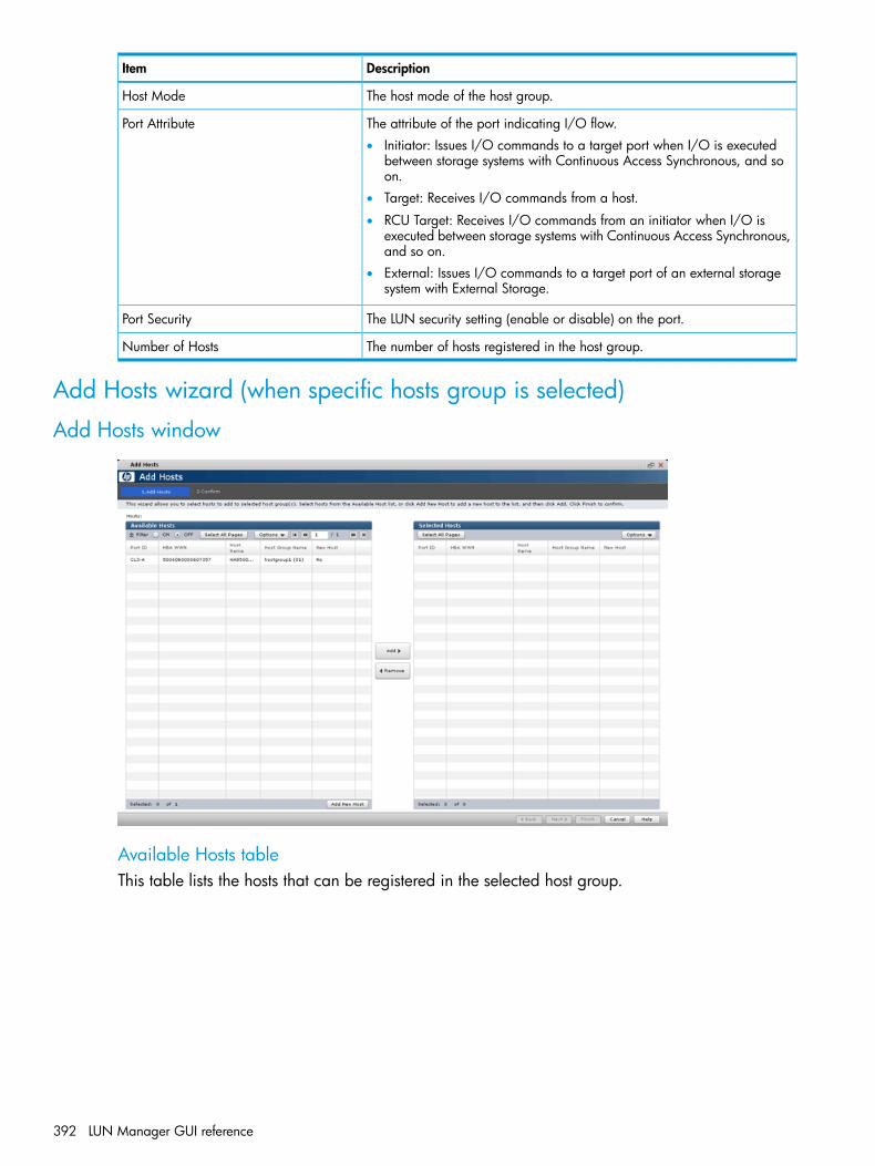
DescriptionItem
The host mode of the host group.Host Mode
The attribute of the port indicating I/O flow.Port Attribute• Initiator: Issues I/O commands to a target port when I/O is executed
between storage systems with Continuous Access Synchronous, and soon.
• Target: Receives I/O commands from a host.
• RCU Target: Receives I/O commands from an initiator when I/O isexecuted between storage systems with Continuous Access Synchronous,and so on.
• External: Issues I/O commands to a target port of an external storagesystem with External Storage.
The LUN security setting (enable or disable) on the port.Port Security
The number of hosts registered in the host group.Number of Hosts
Add Hosts wizard (when specific hosts group is selected)
Add Hosts window
Available Hosts tableThis table lists the hosts that can be registered in the selected host group.
392 LUN Manager GUI reference

DescriptionItem
The identifier of the port.Port ID
The WWN of the port.HBA WWN
The name of the host.Host Name
The name of the host group.Host Group Name
Indicates whether this is a newly added host.New Host• Yes: The host is newly added and has never been connected via a cable
to any port in the storage system.• No: The host has been connected via a cable to another port.
Adds a new host. Note that Port ID and Host Group Name will be blankafter a new host is added.
Add New Host
Adds hosts selected from the Available Hosts table to the Selected Hoststable.
Add
Removes hosts from the Selected Hosts table.Remove
Selected Hosts tableThis table lists hosts selected from the Available Hosts table.
Add Hosts wizard (when specific hosts group is selected) 393

DescriptionItem
The identifier of the port. This field is blank for the host created by clickingAdd New host.
Port ID
The WWN of the port.HBA WWN
The name of the host.Host Name
The name of the host group. Note that this field is blank for the host createdby clicking Add New host.
Host Group Name
Indicates whether this is a newly added host.New Host• Yes: The host is newly added and has never been connected via a cable
to any port in the storage system.• No: The host has been connected via a cable to another port.
Add Hosts Confirm windowConfirm proposed settings, name the task, and then click Apply. The task will be added to theexecution queue.
394 LUN Manager GUI reference

Selected Host Groups tableThis table lists the selected hosts.
DescriptionItem
The identifier of the port.Port ID
The name of the host group.Host Group Name
The host mode of the host group.Host Mode
The attribute of the port indicating I/O flow.Port Attribute• Initiator: Issues I/O commands to a target port when I/O is executed
between storage systems with Continuous Access Synchronous, and soon.
• Target: Receives I/O commands from a host.
• RCU Target: Receives I/O commands from an initiator when I/O isexecuted between storage systems with Continuous Access Synchronous,and so on.
• External: Issues I/O commands to a target port of an external storagesystem with External Storage.
Add Hosts wizard (when specific hosts group is selected) 395

DescriptionItem
The LUN security setting (enable or disable) on the port.Port Security
The number of hosts registered in the host group.Number of Hosts
Selected Hosts tableThis table contains a list of added host groups.
DescriptionItem
The WWN of the port.HBA WWN
The name of the host.Host Name
Delete LUN Paths wizard
Delete LUN Paths window
Selected LUN Paths tableThis table provides information about the selected LUN paths.
DescriptionItem
The identifier of the port.Port ID
The identifier of the selected LUN paths.LUN ID
The LDEV identifier, which is the combination of LDKC, CU, and LDEV.LDEV ID
The name of the LDEV.LDEV Name
The name of the host group.Host Group Name
The size of each logical volume.Capacity
Displays the attribute of the LDEV.Attribute• Command Device: Command device.
• Remote Command Device: Remote command device.
• Online Data Migration: Volume for online data migration.
• -: Volume in which the attribute is not defined.
Removes LUN paths from the Selected LUN Paths table.Remove from Delete process
396 LUN Manager GUI reference

DescriptionItem
Removes LUN paths from the Selected LUN Paths table.Delete all defined LUN paths to aboveLDEVs When this check box is selected, the host groups of all the alternate paths
in the LDEV displayed in the Selected LUNs table must be assigned to theStorage Administrator group permitted to manage them.
Click Next to go to the task setting window, which is indicated in Task NextOption.
Next Task Option
Delete LUN Paths Confirm windowConfirm proposed settings, name the task, and then click Apply. The task will be added to theexecution queue.
Selected LUN Paths table
DescriptionItem
The identifier of the port.Port ID
The identifier of the selected LUN path.LUN ID
The LDEV identifier, which is the combination of LDKC, CU, and LDEV.LDEV ID
The name of the LDEV.LDEV Name
The name of the host group.Host Group Name
The size of each logical volume.Capacity
Displays the attribute of the LDEV.Attribute• Command Device: Command device.
• Remote Command Device: Remote command device.
• Online Data Migration: Volume for online data migration.
• -: Volume in which the attribute is not defined.
Information in this topic assumes only a single task is executed. If multiple tasks are executed, thewindow shows all configuration items. To check information of a configuration item, click Back toreturn to the configuration window, and then click Help
Edit Host wizardUse this wizard to edit host parameters.
Edit Host wizard 397

If you want to change multiple parameters for a host two or more times, wait until the current taskfinishes, and then change the next settings.If you attempt to change the settings again before the current task finishes, only the setting in thesecond task will be applied, so the result might be different from what you expected.
Edit Host window
DescriptionItem
Specify the WWN of the port in 16 digits of hexadecimal numbers.HBA WWN
Specify the host name.Host NameHost name can be up to 64 single-byte ASCII characters (alpha-numeralsand symbols).You cannot use the following symbols: \ / : , ; * ? " < > |You cannot use blanks at the beginning or end of the host name. A hostname is case-sensitive.
If this check box is selected, the changes made in this dialog box will alsoaffect other ports.
Apply same settings to the HBA WWNin all ports
Edit Host Confirm windowConfirm proposed settings, name the task, and then click Apply. The task will be added to theexecution queue.
398 LUN Manager GUI reference
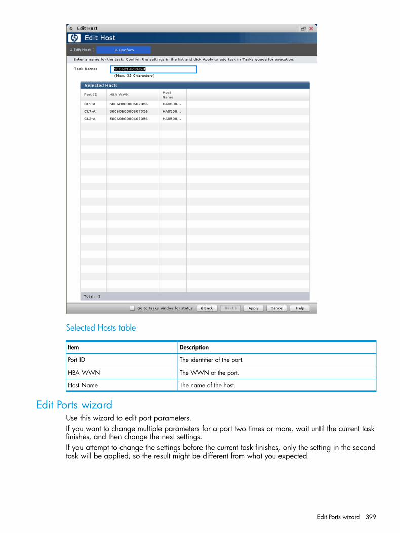
Selected Hosts table
DescriptionItem
The identifier of the port.Port ID
The WWN of the port.HBA WWN
The name of the host.Host Name
Edit Ports wizardUse this wizard to edit port parameters.If you want to change multiple parameters for a port two times or more, wait until the current taskfinishes, and then change the next settings.If you attempt to change the settings before the current task finishes, only the setting in the secondtask will be applied, so the result might be different from what you expected.
Edit Ports wizard 399

Edit Ports window
DescriptionItem
The attribute of the port indicating I/O flow.Port Attribute• Initiator: Issues I/O commands to a target port when I/O is executed
between storage systems with Continuous Access Synchronous, and soon.
• Target: Receives I/O commands from a host.
• RCU Target: Receives I/O commands from an initiator when I/O isexecuted between storage systems with Continuous Access Synchronous,and so on.
• External: Issues I/O commands to a target port of an external storagesystem with External Storage.
• If this port attribute is changed from Target or RCU Target to Initiator orto External, the host group of this port belongs to meta_resource.Therefore, the host group of this port is not displayed in windows.
Select whether LUN security is enabled or disabled.Port Security
Select the data transfer speed, in Gbps, for the selected fibre channel port.Port SpeedIf Auto is selected, the storage system automatically sets the data transferspeed to 1, 2, 4, 8, or 10 Gbps.
CAUTION: If you are using 2-Gbps HBA and switch, set the transfer speedof the CHF (fibre channel adapter) port as 2 Gbps. If you are using 1-GbpsHBA and switch, set the transfer speed of the CHF port as 1 Gbps. If youare using 4-Gbps HBA and switch, set the transfer speed of the CHF portas 4 Gbps. If you are using 8-Gbps HBA and switch, set the transfer speedof the CHF port as 8 Gbps. However, the transfer speed of the CHF portcannot be set as 1 Gbps when the CHF is 8US. Therefore, 1-Gbps HBAand switch cannot be connected. If the Auto Negotiation setting is required,the linkup may become improper at server restart. Check a channel lamp,and if it is blinking, remove and re-insert the cable to perform the signalsynchronization and linkup.When the transfer speed of the CHF port is set to Auto, the data might notbe transferred at the maximum speed depending on the connected device.Confirm the transfer speed appearing in Speed in the Ports list when youstart up the storage system, HBA, or switch. When the transfer speed is notthe maximum speed, select the maximum speed from the list on the right orremove and reinsert the cable.
400 LUN Manager GUI reference
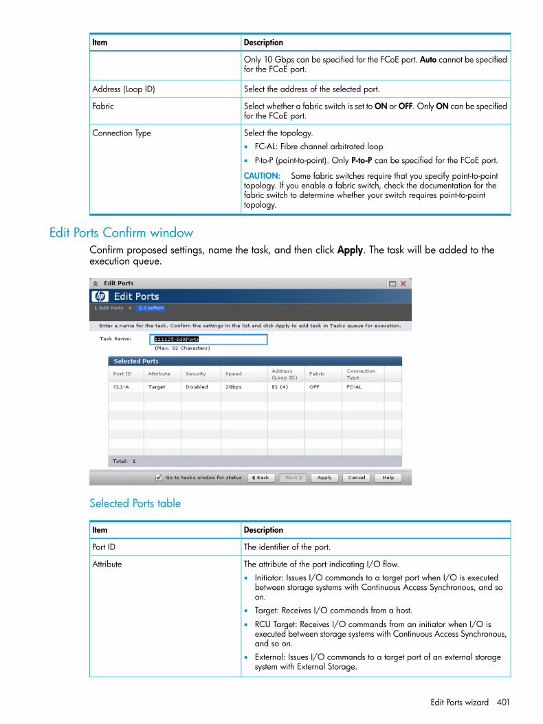
DescriptionItem
Only 10 Gbps can be specified for the FCoE port. Auto cannot be specifiedfor the FCoE port.
Select the address of the selected port.Address (Loop ID)
Select whether a fabric switch is set to ON or OFF. Only ON can be specifiedfor the FCoE port.
Fabric
Select the topology.Connection Type• FC-AL: Fibre channel arbitrated loop
• P-to-P (point-to-point). Only P-to-P can be specified for the FCoE port.
CAUTION: Some fabric switches require that you specify point-to-pointtopology. If you enable a fabric switch, check the documentation for thefabric switch to determine whether your switch requires point-to-pointtopology.
Edit Ports Confirm windowConfirm proposed settings, name the task, and then click Apply. The task will be added to theexecution queue.
Selected Ports table
DescriptionItem
The identifier of the port.Port ID
The attribute of the port indicating I/O flow.Attribute• Initiator: Issues I/O commands to a target port when I/O is executed
between storage systems with Continuous Access Synchronous, and soon.
• Target: Receives I/O commands from a host.
• RCU Target: Receives I/O commands from an initiator when I/O isexecuted between storage systems with Continuous Access Synchronous,and so on.
• External: Issues I/O commands to a target port of an external storagesystem with External Storage.
Edit Ports wizard 401

DescriptionItem
The LUN security setting (enable or disable) on the port.Security
The data transfer speed for the selected fibre channel port in the unit ofGbps (Gigabit per second).
Speed
The address of the selected port.Address (Loop ID)
The status setting (ON or OFF) for a fabric switch.Fabric
The topology of the selected port.Connection Type• FC-AL: Fibre channel arbitrated loop
• P-to-P: Point-to-point
Create Alternative LUN Paths wizard
Create Alternative LUN Paths window
DescriptionItem
Select the resource group in which the host group is created. If Any isselected, among all ports being allocated to the user, ports where the host
Resource Group Name (ID)
group can be add are available in the Available Ports table. If other thanAny is selected, among ports assigned to the selected resource group, portswhere the host group can be add are available in the Available Ports table.
Available Ports tableThis table lists the ports for which alternate paths can be created.
402 LUN Manager GUI reference

DescriptionItem
The identifier of the port.Port ID
The attribute of the port indicating I/O flow.Attribute• Initiator: Issues I/O commands to a target port when I/O is executed
between storage systems with Continuous Access Synchronous, and soon.
• Target: Receives I/O commands from a host.
• RCU Target: Receives I/O commands from an initiator when I/O isexecuted between storage systems with Continuous Access Synchronous,and so on.
• External: Issues I/O commands to a target port of an external storagesystem with External Storage.
The LUN security setting (enable or disable) on the port.Security
The adds ports selected from the Available Ports table to the Selected Portstable.
Add
The removes ports from the Selected Ports table.Remove
Create Alternative LUN Paths wizard 403

Selected Ports table
DescriptionItem
The identifier of the port.Port ID
The attribute of the port indicating I/O flow.Attribute• Initiator: Issues I/O commands to a target port when I/O is executed
between storage systems with Continuous Access Synchronous, and soon.
• Target: Receives I/O commands from a host.
• RCU Target: Receives I/O commands from an initiator when I/O isexecuted between storage systems with Continuous Access Synchronous,and so on.
• External: Issues I/O commands to a target port of an external storagesystem with External Storage.
The LUN security setting (enable or disable) on the port.Security
Create Alternative LUN Paths Confirm windowConfirm proposed settings, name the task, and then click Apply. The task will be added to theexecution queue.
404 LUN Manager GUI reference

Selected Host Groups table
DescriptionItem
The identifier of the port.Port ID
The name of the host group.Host Group Name
The host mode of the host group.Host Mode
The attribute of the port indicating I/O flow.Port Attribute• Initiator: Issues I/O commands to a target port when I/O is executed
between storage systems with Continuous Access Synchronous, and soon.
• Target: Receives I/O commands from a host.
• RCU Target: Receives I/O commands from an initiator when I/O isexecuted between storage systems with Continuous Access Synchronous,and so on.
• External: Issues I/O commands to a target port of an external storagesystem with External Storage.
The LUN security setting (enable or disable) on the port.Port Security
The number of hosts registered in the host group.Number of Hosts
The resource group name and identifier of the resource group containingthe host groups.
Resource Group Name (ID)
Added LUNs table
DescriptionItem
The identifier of the added logical unit.LUN ID
The identifier of the LDEV.LDEV ID
The LDEV identifier, which is the combination of LDKC, CU, and LDEV.LDEV Name
The emulation types for each logical volume (or logical device). For LUSEvolumes, an asterisk (*) and a number appear on the right of the emulation
Emulation Type
type. For example, OPEN-9*3 indicates that three OPEN-9 volumes arecombined.
The size of each logical volume.Capacity
The identifier of the parity group.Parity Group ID
The number of paths set for the LDEV.Number of Paths
Create Alternative LUN Paths wizard 405

Copy LUN Paths wizard
Copy LUN Paths window
Available Host Groups table
This table lists the host groups for which LU paths can be copied. Only the host group assigned tothe logged-on user are available.
DescriptionItem
The identifier of the port.Port ID
The name of the host group.Host Group Name
406 LUN Manager GUI reference
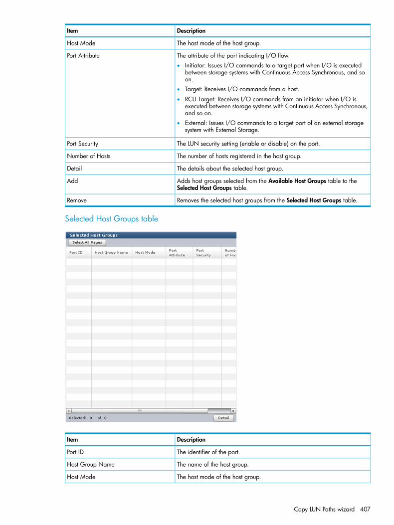
DescriptionItem
The host mode of the host group.Host Mode
The attribute of the port indicating I/O flow.Port Attribute• Initiator: Issues I/O commands to a target port when I/O is executed
between storage systems with Continuous Access Synchronous, and soon.
• Target: Receives I/O commands from a host.
• RCU Target: Receives I/O commands from an initiator when I/O isexecuted between storage systems with Continuous Access Synchronous,and so on.
• External: Issues I/O commands to a target port of an external storagesystem with External Storage.
The LUN security setting (enable or disable) on the port.Port Security
The number of hosts registered in the host group.Number of Hosts
The details about the selected host group.Detail
Adds host groups selected from the Available Host Groups table to theSelected Host Groups table.
Add
Removes the selected host groups from the Selected Host Groups table.Remove
Selected Host Groups table
DescriptionItem
The identifier of the port.Port ID
The name of the host group.Host Group Name
The host mode of the host group.Host Mode
Copy LUN Paths wizard 407
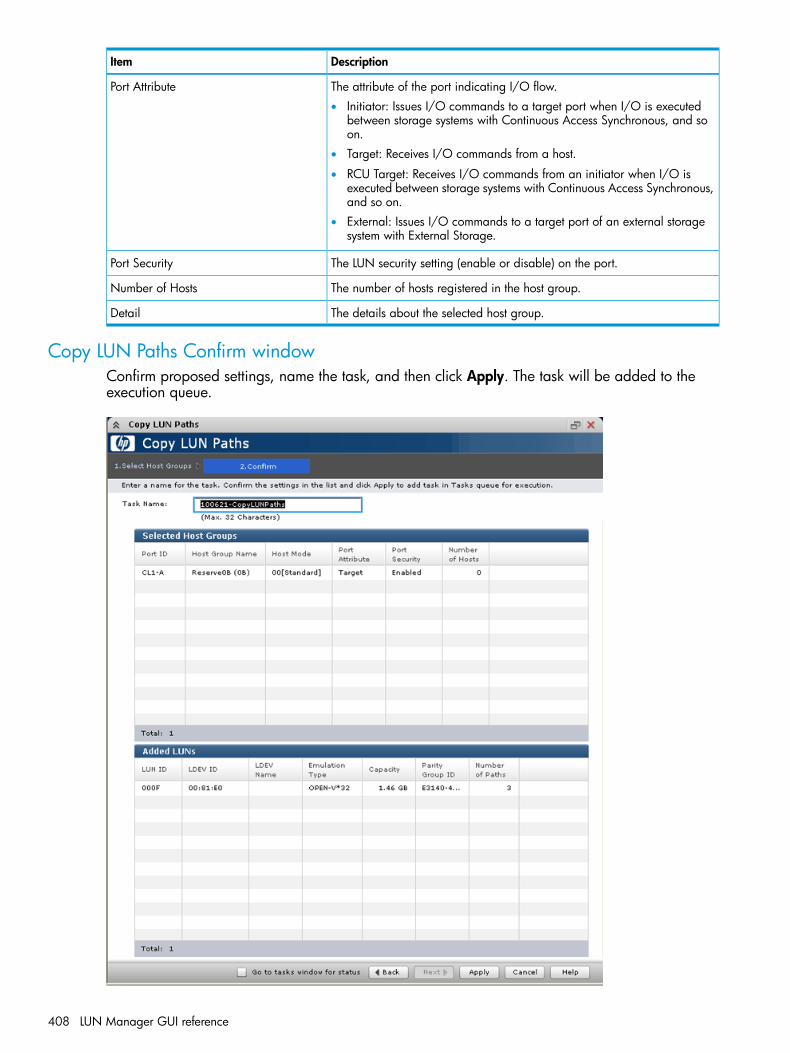
DescriptionItem
The attribute of the port indicating I/O flow.Port Attribute• Initiator: Issues I/O commands to a target port when I/O is executed
between storage systems with Continuous Access Synchronous, and soon.
• Target: Receives I/O commands from a host.
• RCU Target: Receives I/O commands from an initiator when I/O isexecuted between storage systems with Continuous Access Synchronous,and so on.
• External: Issues I/O commands to a target port of an external storagesystem with External Storage.
The LUN security setting (enable or disable) on the port.Port Security
The number of hosts registered in the host group.Number of Hosts
The details about the selected host group.Detail
Copy LUN Paths Confirm windowConfirm proposed settings, name the task, and then click Apply. The task will be added to theexecution queue.
408 LUN Manager GUI reference
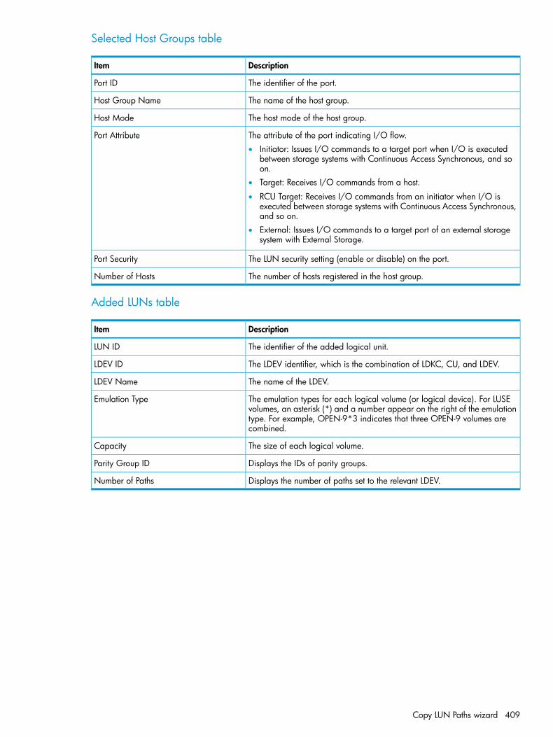
Selected Host Groups table
DescriptionItem
The identifier of the port.Port ID
The name of the host group.Host Group Name
The host mode of the host group.Host Mode
The attribute of the port indicating I/O flow.Port Attribute• Initiator: Issues I/O commands to a target port when I/O is executed
between storage systems with Continuous Access Synchronous, and soon.
• Target: Receives I/O commands from a host.
• RCU Target: Receives I/O commands from an initiator when I/O isexecuted between storage systems with Continuous Access Synchronous,and so on.
• External: Issues I/O commands to a target port of an external storagesystem with External Storage.
The LUN security setting (enable or disable) on the port.Port Security
The number of hosts registered in the host group.Number of Hosts
Added LUNs table
DescriptionItem
The identifier of the added logical unit.LUN ID
The LDEV identifier, which is the combination of LDKC, CU, and LDEV.LDEV ID
The name of the LDEV.LDEV Name
The emulation types for each logical volume (or logical device). For LUSEvolumes, an asterisk (*) and a number appear on the right of the emulation
Emulation Type
type. For example, OPEN-9*3 indicates that three OPEN-9 volumes arecombined.
The size of each logical volume.Capacity
Displays the IDs of parity groups.Parity Group ID
Displays the number of paths set to the relevant LDEV.Number of Paths
Copy LUN Paths wizard 409

Remove Hosts wizard
Remove Hosts window
Selected Hosts table
DescriptionItem
The identifier of the port.Port ID
The WWN of the port.HBA WWN
The name of the host.Host Name
The name of the host group.Host Group Name
If this check box is selected, selected hosts are removed from all host groupscontaining the hosts in the storage system.
Remove selected hosts from all host groupscontaining the hosts in the storage system
Remove Hosts Confirm windowConfirm proposed settings, name the task, and then click Apply. The task will be added to theexecution queue.
410 LUN Manager GUI reference
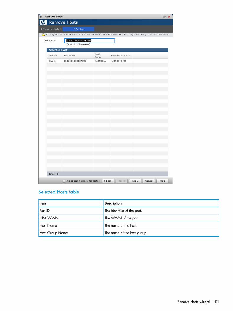
Selected Hosts table
DescriptionItem
The identifier of the port.Port ID
The WWN of the port.HBA WWN
The name of the host.Host Name
The name of the host group.Host Group Name
Remove Hosts wizard 411

Edit UUIDs wizard
Edit UUIDs window
DescriptionItem
For an OPEN VMS server host: The total length of the Prefix and the InitialNumber may not exceed 5 characters. If the Prefix is 5 characters, you maynot specify an Initial Number and vice versa.
Prefix
For a server host other than OPEN VMS: The total length of the Prefix andthe Initial Number may not exceed 64 characters. If the Prefix is 64characters, you may not specify an Initial Number and vice versa.The following rules apply to UUID:
• These characters cannot be used: \ / : , ; * ? " < > |
• A space character cannot be used for the first and the last characters.
• UUIDs are case-sensitive. For example, Abc and abc are different UUIDs.
For an OPEN VMS server host: The total length of the Prefix and the InitialNumber may not exceed 5 characters. If the Prefix is 5 characters, you maynot specify an Initial Number and vice versa.
Initial Number
For a server host other than OPEN VMS: The total length of the Prefix andthe Initial Number may not exceed 64 characters. If the Prefix is 64characters, you may not specify an Initial Number and vice versa.The following rules apply to the initial number.Example:
• 1: Up to 9 numbers are added (1, 2, 3 ... 9)
• 08: Up to 92 numbers are added (08, 09, 10 ... 99)(If the host mode is OpenVMS, the numbers are: 8, 9, 10 ... 99)
• 23: Up to 77 numbers are added (23, 24, 25 ... 99)
CAUTION: If UUID is blank, the UUID setting is released.
Edit UUIDs Confirm windowConfirm proposed settings, name the task, and then click Apply. The task will be added to theexecution queue.
412 LUN Manager GUI reference

Selected LUNs table
DescriptionItem
The identifier of the port.Port ID
The logical units whose UUID has been changed.LUN ID
The LDEV identifier, which is the combination of LDKC, CU, and LDEV.LDEV ID
The name of the LDEV.LDEV Name
The identifies the set or changed UUID. A blank field indicates that the UUIDis released.
UUID
The emulation types for each logical volume (or logical device). For LUSEvolumes, an asterisk (*) and a number appear on the right of the emulation
Emulation Type
type. For example, OPEN-9*3 indicates that three OPEN-9 volumes arecombined.
The size of each logical volume.Capacity
Edit UUIDs wizard 413
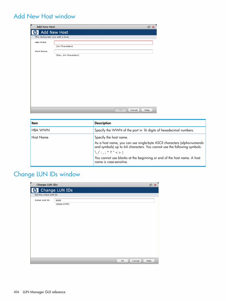
Add New Host window
DescriptionItem
Specify the WWN of the port in 16 digits of hexadecimal numbers.HBA WWN
Specify the host name.Host NameAs a host name, you can use single-byte ASCII characters (alpha-numeralsand symbols) up to 64 characters. You cannot use the following symbols:\ / : , ; * ? " < > |You cannot use blanks at the beginning or end of the host name. A hostname is case-sensitive.
Change LUN IDs window
414 LUN Manager GUI reference

Setting field
DescriptionItem
Specify the initial LUN ID in 4 digits of hexadecimal numbers (from 0000to 07FF). If multiple LUs are selected, LUN IDs are set consecutively fromthe specified LUN ID.
Initial LUN ID
Delete Host Groups window
Selected Host Groups table
DescriptionItem
The identifier of the port.Port ID
The name of the host group.Host Group Name
The host mode of the host group.Host Mode
Delete Host Groups window 415

DescriptionItem
The attribute of the port indicating I/O flow.Port Attribute• Initiator: Issues I/O commands to a target port when I/O is executed
between storage systems with Continuous Access Synchronous, and soon.
• Target: Receives I/O commands from a host.
• RCU Target: Receives I/O commands from an initiator when I/O isexecuted between storage systems with Continuous Access Synchronous,and so on.
• External: Issues I/O commands to a target port of an external storagesystem with External Storage.
The LUN security setting (enable or disable) on the port.Port Security
The number of hosts registered in the host group.Number of Hosts
The details about the selected host group.Detail
Delete Login WWNs window
Selected Login WWNs table
DescriptionItem
The identifier of the port.Port ID
The WWN of the port.HBA WWN
The name of the host.Host Name
The name of the host group.Host Group Name
416 LUN Manager GUI reference
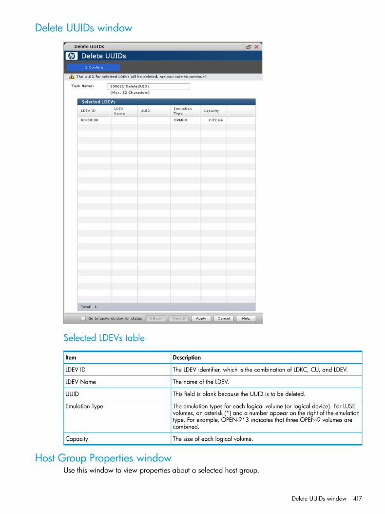
Delete UUIDs window
Selected LDEVs table
DescriptionItem
The LDEV identifier, which is the combination of LDKC, CU, and LDEV.LDEV ID
The name of the LDEV.LDEV Name
This field is blank because the UUID is to be deleted.UUID
The emulation types for each logical volume (or logical device). For LUSEvolumes, an asterisk (*) and a number appear on the right of the emulation
Emulation Type
type. For example, OPEN-9*3 indicates that three OPEN-9 volumes arecombined.
The size of each logical volume.Capacity
Host Group Properties windowUse this window to view properties about a selected host group.
Delete UUIDs window 417
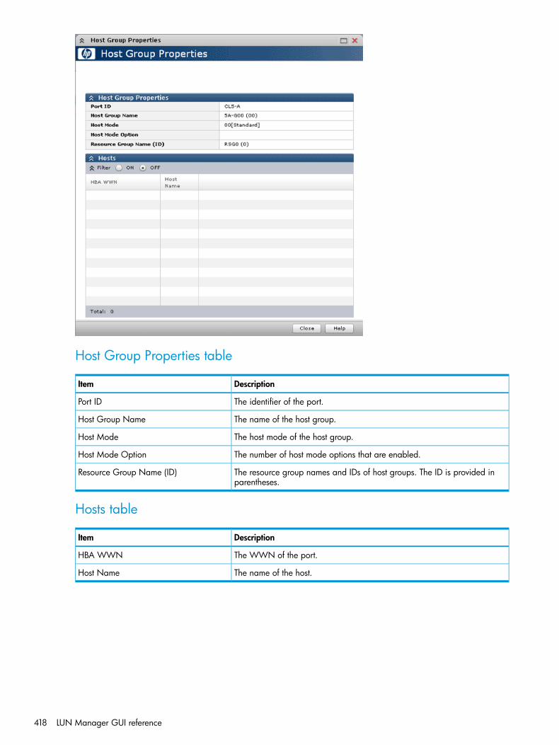
Host Group Properties table
DescriptionItem
The identifier of the port.Port ID
The name of the host group.Host Group Name
The host mode of the host group.Host Mode
The number of host mode options that are enabled.Host Mode Option
The resource group names and IDs of host groups. The ID is provided inparentheses.
Resource Group Name (ID)
Hosts table
DescriptionItem
The WWN of the port.HBA WWN
The name of the host.Host Name
418 LUN Manager GUI reference
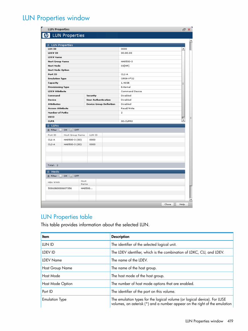
LUN Properties window
LUN Properties tableThis table provides information about the selected LUN.
DescriptionItem
The identifier of the selected logical unit.LUN ID
The LDEV identifier, which is the combination of LDKC, CU, and LDEV.LDEV ID
The name of the LDEV.LDEV Name
The name of the host group.Host Group Name
The host mode of the host group.Host Mode
The number of host mode options that are enabled.Host Mode Option
The identifier of the port on this volume.Port ID
The emulation types for the logical volume (or logical device). For LUSEvolumes, an asterisk (*) and a number appear on the right of the emulation
Emulation Type
LUN Properties window 419

DescriptionItem
type. For example, OPEN-9*3 indicates that three OPEN-9 volumes arecombined.
The size of the logical volume.Capacity
The provisioning type assigned to this logical volume.Provisioning Type• Basic: Internal volume.
• THP: THP V-VOL.
• External: External volume.
• Snapshot: Fast Snap volume or Snapshot volume.
Displays the attribute of the LDEV.LDEV Attribute• Command Device: Command device.
• Remote Command Device: Remote command device.
• Online Data Migration: Volume for online data migration.
• -: Volume in which the attribute is not defined.
If the logical volume is used as a command device, indicates the status ofthe attributes on this LDEV.
Command Device Attributes
• Security: Indicates the status of command device security is (enable ordisable).
• User Authentication: Indicates the status of user authentication (enableor disable).
• Device Group Definition: Indicates the status of device group definition(enable or disable).
Indicates the setting (Enabled or Disabled) of command device security.Security
Indicates the setting (Enabled or Disabled) of the command device userauthentication.
User Authentication
Indicates the setting (Enabled or Disabled) of the command device groupdefinition.
Device Group Definition
The access attribute assigned to this LDEV.Access Attribute• Read/Write: Both read and write operations are permitted on the logical
volume.• Read-only: Read operations are permitted on the logical volume.
• Protect: Neither read nor write operations are permitted.
The number of paths set for the LDEV.Number of Paths
The user-definable LUN identifier. This field is blank if the UUID is not set.UUID
The cache logical partition numbers.CLPRFor detailed information about CLPRs, see the HP XP P9000 Cache PartitionUser Guide.
LUNs tableThis table provides information about the LUN ID registered for the selected LDEV.
DescriptionItem
The identifier of the port.Port ID
The name of the host group.Host Group Name
The identifier of the logical unit.LUN ID
420 LUN Manager GUI reference
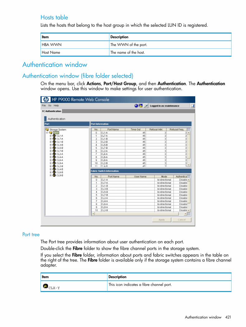
Hosts tableLists the hosts that belong to the host group in which the selected LUN ID is registered.
DescriptionItem
The WWN of the port.HBA WWN
The name of the host.Host Name
Authentication window
Authentication window (fibre folder selected)On the menu bar, click Actions, Port/Host Group, and then Authentication. The Authenticationwindow opens. Use this window to make settings for user authentication.
Port treeThe Port tree provides information about user authentication on each port.Double-click the Fibre folder to show the fibre channel ports in the storage system.If you select the Fibre folder, information about ports and fabric switches appears in the table onthe right of the tree. The Fibre folder is available only if the storage system contains a fibre channeladapter.
DescriptionItem
This icon indicates a fibre channel port.CLX-Y
Authentication window 421
Port information list
DescriptionItem
The fibre channel port names.Port Name
The period of time between authentication sessions to a same port. If the previousauthentication session to a port failed, the next authentication session starts after thespecified period of time elapses. The unit is seconds.
Time out
If authentication fails for the number of times specified in Refusal Freq., connection tothe port fails. Refusal Intvl. shows the interval (in minutes) from when connection to aport fails to when the next authentication session starts.
Refusal Intvl.
The number of times that authentication is allowed for connection to a port. Ifauthentication fails for the specified number of times, connection to the port fails.
Refusal Freq.
Fabric Switch information list
DescriptionItem
The fibre channel port name.Port Name
The user name of the fabric switch.User Name
The mode of authentication between ports and fabric switches.Mode• bidirectional: The authentication mode is mutual.
• unidirectional: The authentication mode is not mutual.
Indicates whether to perform authentication for the fabric switch.Authentication• Enable: The fabric switch is a target of user authentication.
• Disable: The fabric switch is not a target of user authentication.
Authentication window (fibre port selected)On the menu bar, click Actions, Port/Host Group, and then Authentication. The Authenticationwindow opens. Use this window to make settings for user authentication.
422 LUN Manager GUI reference

Port treeUse this tree to find information about user authentication on each port. When you select a portfrom this tree, the Authentication Information (Target) list on the right provides user information ofthe hosts that are registered on the port. In addition, the Authentication Information (Host) list belowthe Authentication Information (Target) list provides the user information of the selected port.Double-click the Fibre folder to view all fibre channel ports in the storage system. The Fibre folderis available only if the storage system contains a fibre channel adapter. Double-click the fibrechannel ports to view host groups in that port. The host group name appears beside the icon.
DescriptionItem
Indicates a fibre channel port.CLX-Y
Indicates that the host group performs authentication of hosts.host group name
Indicates that the host group does not perform authentication of hosts.host group name
Authentication window 423

Authentication information (target) listThe list on the right provides user information of the host groups that are allowed to connect to theport or host group specified in the tree.
DescriptionItem
The names of the host group.Group Name
The user name of the host group. When the user name is not defined for a host group, thiscolumn is blank.
User Name
Indicates whether to perform user authentication for the host.Authentication• Enable: The host is a target of user authentication.
• Disable: The host is not a target of user authentication.
Authentication information (host) listBelow the User Information (Target) list appears a list that provides user information of the hostselected in the port or host group in the tree. In this list, you can register up to 64 user informationitems.
DescriptionItem
The name of the host group.Group Name
The user name of the host. When the user name is not defined for a host, this column is blank.User Name
Indicates the protocol in use for user authentication. Always CHAP.Protocol
Add New User Information (Host) window
DescriptionItem
Select the group name where the user will be registered.Group Name
Specify the user name of the host. Up to 16 alphanumeric characters can be used.User Name
Specify the secret to be used for host authentication.SecretUse 12 to 32 characters, including alphanumerics, spaces, and the following symbols: . - +@ _ = : / [ ] , ~
Specify the secret again for confirmation. An error occurs if you enter incorrect characters,and then click OK.
Re-enter Secret
The protocol to be used for user authentication. This protocol is always CHAP(Challenge-Handshake Authentication Protocol).
Protocol
424 LUN Manager GUI reference

Change User Information (Host) window
DescriptionItem
The group name where the user is registered.Group Name
Specify the user name of the host. Up to 16 alphanumeric characters can be used.User Name
Specify the secret to be used for host authentication.SecretUse 12 to 32 characters, including alphanumerics, spaces, and the following symbols: . - +@ _ = : / [ ] , ~
Specify the secret again for confirmation. An error occurs if you enter incorrect characters,and then click OK.
Re-enter Secret
The protocol to be used for user authentication. This protocol is always CHAP(Challenge-Handshake Authentication Protocol).
Protocol
Clear Authentication information window
DescriptionItem
The item number.No
The group name to be deleted.Group Name
The name of the user to be deleted.User Name
Authentication window 425

Specify Authentication Information window
DescriptionItem
The group name where the user is registered.Group Name
Specify the user name of the host. Up to 16 alphanumeric characters can be used.User Name
Specify the secret to be used for host authentication.SecretUse 12 to 32 characters, including alphanumerics, spaces, and the following symbols: . - +@ _ = : / [ ] , ~
Specify the secret again for confirmation. An error occurs if you enter incorrect characters,and then click OK.
Re-enter Secret
Edit Command Devices wizardThe System Administrator can enter RAID Manager commands from open-system hosts to performContinuous Access Synchronous or Business Copy operations or both on logical devices. Forexample, RAID Manager commands can be used to create and split pairs. If you want to allowthe System Administrator to enter RAID Manager commands from open-system hosts, you mustspecify at least one logical device as the command device. If desired, you must also apply commanddevice security to other logical devices in the storage system.Use Edit Command Devices window to edit command devices.
426 LUN Manager GUI reference
Procedure 34 To open the Edit Command Devices window:1. Select LDEVs in one of the following ways.
• In the Storage Systems tree, click Logical Devices and select the LDEVs tab.• In the Storage Systems tree, click Ports/Host Groups and select a port, and then select a
host group. After that, select the LUNs tab.2. On the menu bar, click Actions, Logical Device, and then Edit Command Devices. Or, click
Edit Command Devices. The Edit Command Devices window opens.
CAUTION: The following volumes cannot be specified as a command device:• Volume whose access attribute is other than read/write• Volume reserved by Auto LUN• Continuous Access Synchronous volume• Business Copy volume• Continuous Access Journal volume• Virtual volume (V-VOL) for Fast Snap or Snapshot.• Volume reserved by Data Retention• System disk• Journal volume• Pool volume• Remote command device• Quorum disk for External Storage Access Manager• Volume for online data migration
Edit Command Devices windowIf you want to enable command device security, user authentication, and device group definition,you must enable the command device in this window.If the command device is disabled, you cannot enable command device security, user authentication,and device group definition.
Edit Command Devices wizard 427

DescriptionItem
Select Enable to enable command devices. Select Disable to releasecommand devices.
Command Device
Select Enable to apply command device security to a logical device in astorage system. Select Disable to release command device security.
Command Device Security
If you want to protect logical volumes from the use of RAID Managercommands, you must apply command device security to the logical volumes.If command device security is applied to a logical device, the logical devicewill not be affected by RAID Manager commands issued via commanddevices from the hosts*.
Select Enable to apply user authentication to a command device. SelectDisable to release user authentication*.
User Authentication
Select Enable to apply device group definition to a command device. SelectDisable to release device group definition*.
Device Group Definition
* For details about a command device attribute settings, see the HP P9000 RAID Manager User Guide.
Edit Command Devices Confirm windowConfirm proposed settings, name the task, and then click Apply. The task will be added to theexecution queue.
428 LUN Manager GUI reference

Selected LDEVs table
DescriptionItem
The LDEV identifier, which is the combination of LDKC, CU, and LDEV.LDEV ID
The name of the LDEV.LDEV Name
The identifier of the parity group.Parity Group ID
The emulation types for each logical volume (or logical device). For LUSEvolumes, an asterisk (*) and a number appear on the right of the emulation
Emulation Type
type. For example, OPEN-9*3 indicates that three OPEN-9 volumes arecombined.
The size of each logical volume.Capacity
The provisioning types for each logical volume.Provisioning Type• Basic: Internal volume.
• External: External volume.
• THP: V-VOL of Thin Provisioning.
• Snapshot: Fast Snap volume or Snapshot volume.
Edit Command Devices wizard 429

DescriptionItem
Indicates whether the selected logical device is a command device.Command Device• Enabled: The command devices are enabled.
• Disabled: The logical device is not a command device.
Indicates whether command device security is applied to the selectedcommand device.
Command Device Security
• Enabled: Command device security is applied to the command device.
• Disabled: Command device security is not applied to the commanddevice.
Indicates whether user authentication is applied to the selected commanddevice.
User Authentication
• Enabled: User authentication is applied to the command device.
• Disabled: User authentication is not applied to the command device.
Indicates whether the device group definition is applied to the selectedcommand device.
Device Group Definition
• Enabled: Device group definition is applied to the command device.
• Disabled: Device group definition is not applied to the command device.
Host-Reserved LUNs window
LUNs tableLUNs reserved by hosts are displayed.
DescriptionItem
Displays names of ports.Port ID
Displays IDs of the LUNs.LUN ID
430 LUN Manager GUI reference
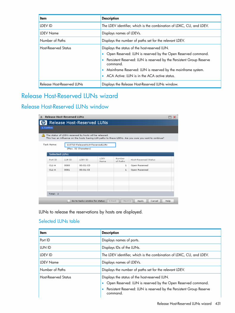
DescriptionItem
The LDEV identifier, which is the combination of LDKC, CU, and LDEV.LDEV ID
Displays names of LDEVs.LDEV Name
Displays the number of paths set for the relevant LDEV.Number of Paths
Displays the status of the host-reserved LUN.Host-Reserved Status• Open Reserved: LUN is reserved by the Open Reserved command.
• Persistent Reserved: LUN is reserved by the Persistent Group Reservecommand.
• Mainframe Reserved: LUN is reserved by the mainframe system.
• ACA Active: LUN is in the ACA active status.
Displays the Release Host-Reserved LUNs window.Release Host-Reserved LUNs
Release Host-Reserved LUNs wizard
Release Host-Reserved LUNs window
LUNs to release the reservations by hosts are displayed.
Selected LUNs table
DescriptionItem
Displays names of ports.Port ID
Displays IDs of the LUNs.LUN ID
The LDEV identifier, which is the combination of LDKC, CU, and LDEV.LDEV ID
Displays names of LDEVs.LDEV Name
Displays the number of paths set for the relevant LDEV.Number of Paths
Displays the status of the host-reserved LUN.Host-Reserved Status• Open Reserved: LUN is reserved by the Open Reserved command.
• Persistent Reserved: LUN is reserved by the Persistent Group Reservecommand.
Release Host-Reserved LUNs wizard 431
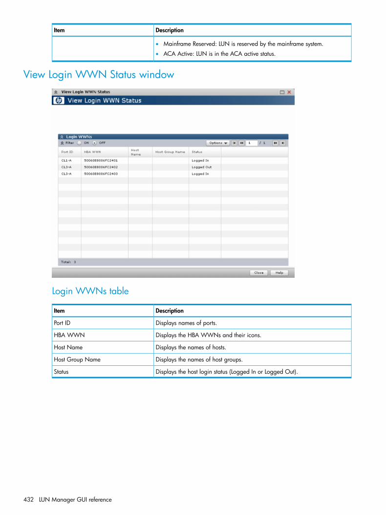
DescriptionItem
• Mainframe Reserved: LUN is reserved by the mainframe system.
• ACA Active: LUN is in the ACA active status.
View Login WWN Status window
Login WWNs table
DescriptionItem
Displays names of ports.Port ID
Displays the HBA WWNs and their icons.HBA WWN
Displays the names of hosts.Host Name
Displays the names of host groups.Host Group Name
Displays the host login status (Logged In or Logged Out).Status
432 LUN Manager GUI reference

Glossaryallocation The ratio of allocated storage capacity versus total capacity as a percentage. Allocated storage
refers to those logical devices (LDEVs) that have paths assigned to them. Allocated storage capacityis the sum of the storage of these LDEVs. Total capacity is the sum of the capacity of all LDEVson the disk array.
array group A group of four or eight physical hard disk drives (HDDs) installed in a P9000 or XP disk arrayand assigned a common RAID level. RAID1 array groups consist of four (2D+2D) or eight HDDs(4D+4D). RAID5 array groups include a parity disk, but also consist of four (3D+1P) or eightHDDs (7D+1P). All RAID6 array groups are made up of eight HDDs (6D+2P). This is also knownas a parity group or a RAID group.
CLI Command-line interface. An interface comprised of various commands which are used to controloperating system responses.
CLPR Cache logical partition.command device A volume in the disk array that accepts Continuous Access, Business Copy, or P9000 for Business
Continuity Manager control operations, which are then executed by the array.CU Control unit.DKC Disk controller.HBA Host bus adapter.HDD Hard disk drive.LDKC Logical disk controller.LUN Logical unit number. A LUN results from mapping a logical unit number, port ID, and LDEV ID to
a RAID group. The size of the LUN is determined by the emulation mode of the LDEV and thenumber of LDEVs associated with the LUN.
LUSE Logical Unit Size Expansion. The LUSE feature is available when the HP StorageWorks LUNManager product is installed, and allows a LUN, normally associated with only a single LDEV,to be associated with 1 to 36 LDEVs. Essentially, LUSE makes it possible for applications to accessa single large pool of storage.
parity group A set of hard disk drives that have the same capacity and that are treated as one group. A paritygroup contains both user data and parity information, which enables user data to be accessedif one or more drives in the group is not available.
path A path is created by associating a port, a target, and a LUN ID with one or more LDEVs. Alsoknown as a LUN.
port A physical connection that allows data to pass between a host and the disk array. The numberof ports on a disk array depends on the number of supported I/O slots and the number of portsavailable per I/O adapter. The P9000 and XP family of disk arrays supports Fibre Channel (FC)ports and other port types. Ports are named by port group and port letter, such as CL1-A. CL1 isthe group; A is the port letter.
RAID level A configuration of disk drives that uses striping, mirroring, and parity to improve performanceand data availability and reliability.
RAID Manager The CLI configuration and replication tool for the P9000 or XP disk array that system administratorscan use to enter RAID Manager commands from open-system hosts to perform Continuous Access,Business Copy, Database Validator, and Data Retention operations, as well as provisioningcommands on logical devices.
RAID1/5 Specific RAID architectures.Remote WebConsole
A browser-based program installed on the SVP that allows you to configure and manage the diskarray.
RPM Red Hat package manager.SAS Serial Attached SCSI.SSD Solid state disk. A high-performance storage device that contains no moving parts. An SSD
contains DRAM or EEPROM memory boards, a memory bus board, a CPU, and a battery card.
433

SVP Service processor. A computer built into a disk array. The SVP, used only by an HP servicerepresentative, provides a direct interface to the disk array.
VOL, vol Volume.volume Volume on disk. An accessible storage area on disk, either physical or virtual.WWN World Wide Name. A unique identifier assigned to a Fibre Channel device.
434 Glossary

Index
Aaccess attributes
assigning to a volume, 166changing to read-only or protect, 166changing to read/write, 168configuring, 164expiration lock, 168overview, 164permitted operations, 165requirements, 164reserving volumes, 169restrictions, 165retention term, 169workflow, 165
alternate LU paths, 172Attribute command, 167, 168authentication
configuring on fibre channel ports, 203configuring on fibre channels, 199fabric switch, 197fibre channel, 192host settings, 193hosts and host groups, 194hosts, enabling fibre channel switch, 205mutual, 193mutual of ports, 199port settings, 194users, 193
Bbasic provisioning
overview, 14workflow, 17
boundary values for RAID levels, 50enhanced data protection on SATA drive, 50
Business Copy, 84
Ccapacity of a slot, 50Changing External LDEV Capacity, 158CHAP authentication, 192, 194, 195, 196, 197, 198,
199, 200, 202, 203, 204command device, 166contacting HP, 217Continuous Access Journal, 84Continuous Access Synchronous, 83conventions
document, 218storage capacity values, 218text symbols, 219
correspondence table for defining devices, 187Create LDEV function, 51custom-sized provisioning
overview, 16
Ddata retention strategies, 22Data Retention Window, 167Data Retention window, 360data transfer speed
fibre channel ports, 174devices
correspondence table, 187document
conventions, 218related information, 217
documentationHP website, 217providing feedback, 217
EError Detail dialog box, 213, 362expanded LU provisioning
overview, 16expiration lock, 360
enabling/disabling, 168
Ffabric switch, 197fabric topology, 176FC-AL (fibre channel-arbitrated loop) topology, 176fibre channel authentication
setting, 192fibre channel ports
addresses, 175configuring, 174, 176configuring authentication, 199, 203data transfer speed, 174registering user information, 203setting port information, 203
fibre channel switchauthentication settings and connection results, 199clearing user information, 204enabling or disabling authentication, 205registering user information, 204setting authentication mode, 205
fibre channel topologyoverview, 176
Finding WWNHP-UX, 182
finding WWNAIX, 182IRIX, 182Oracle Solaris, 182Sequent, 182Windows, 181
fixed-sized provisioningoverview, 14
435

Hhelp
obtaining, 217host authentication
disabling in a host group, 199enabling in a host group, 199
host bus adapterschanging WWNs, 205deleting from host group, 207
host group 0, 191initializing, 207
host groups, 171authentication, 194changing host mode, 206changing name, 206creating, 183deleting, 208deleting host bus adapters, 207
host mode optionslisted and defined, 179
host modeslisted and defined, 177
hostsauthentication, 194changing host user information, 201configuring, 177configuring workflow, 177deleting host user information, 201registering host group user information, 202registering host user information, 200registering in host group, 183
HPsubscription service, 217technical support, 217
Llaunching LUSE, 67LDEVs
blocking, 55changing settings, 55confirming SSID, 54creating, 51deleting (converting to free space), 57editing name, 56editing SSID, 54formatting, 57, 58, 60formatting in a parity group, 60removing from registering task, 55restoring if blocked, 56
LDEVs released from a LUSE volumespecifications and restrictions, 65
LDEVs used to configure a LUSE volumerules, restrictions, and guidelines, 65
leap year, 168logical units, 171logical volumes
managing, 171LU paths, 171
configuring, 185
configuring on fibre-channel, 171defining, 185defining alternate, 187deleting, 188managing, 188rules, restrictions, and guidelines, 172viewing settings, 189
LUNdefined, 172
LUN securityenabling on ports, 192example of disabling, 191example of enabling, 190settings for authentication of hosts, 193settings for authentication of ports, 194
LUN security on ports, 190disabling, 192
LUSE, 64launching, 67maintenance, 71
LUSE feature, 64LUSE provisioning
workflow, 67
Mmanagement area capacity
calculated, 50open-systems volume, 49
managing hosts, 205managing logical volumes
rules, restrictions, and guidelines, 172workflow, 173
meta_resource, 29monitoring capacity, 143mutual authentication, 193
ports, 199, 202
Nnicknames
changing, 205
Ooperating system and file system capacity, 79
Pparity groups
configuring volumes, 51performance
optimizing by setting data transfer speed for a fibrechannel port, 174
Performance Monitorautomatic starting considerations, 165
point-to-point topology, 176pool capacity
decreasing, 154increasing, 152stop decreasing, 156
pool informationviewing, 150
436 Index

pool namechanging, 153
pool subscription limitchanging, 148
pool thresholdchanging, 147
pool-VOLsrequirements, 76
poolscreating, 133deleting, 157managing, 150recovering, 154requirements, 75
portsmutual authentication, 199rules, restrictions, and guidelines, 172
provisioning key terms, 22
QQuick Format function, 58
RRAID levels
boundary values, 50boundary values (enhanced data protection on SATA
drive), 50reclaiming pages in a V-VOL, 160related documentation, 217reserving volumes with access attributes, 169resource groups
adding resources to, 31assignments, 29changing name, 32creating, 30deleting, 33example not sharing a port, 28example sharing a port, 26license requirements, 30meta_resource, 29overview, 26removing resources from, 32resource lock, 29rules, restrictions, and guidelines, 30strategies, 22system configuration, 26user groups, 29
resource lock, 29retention term
changing access attributes, 169
SS-VOL disable attribute, 169secret, in CHAP authentication, 194shared memory requirements for provisioning, 24SIM reference codes
listed, 148SIMs
completing automatically, 149
completing manually, 149overview, 148
slot capacity, 50Snapshot, 85SSID
confirming, 54editing, 54requirements, 45
storage capacity valuesconventions, 218
subscription limit of a poolchanging, 148
subscription service, HP, 217symbols in text, 219system disk
rules, restrictions, and guidelines, 63system requirements for provisioning, 23
Ttechnical support
HP, 217service locator website, 217
Technical Support Center, 216text symbols, 219thin provisioning
configuring, 74example, 20overview, 18, 74requirements, 74work flow, 20workflow, 86
tier capacityreserving, 112reserving example, 112
tier relocationrules, restrictions, and guidelines, 96
tieringworkflow, 123
tiering policy, 109changing execution modes example, 119notes on using, 114overview, 107relationship with graphs, 110relationship with tiers, 110reserving tier capacity, 112setting on a V-VOL, 109
topology, 176example of FC-AL and point-to-point, 177
TP-VOL requirements, 77troubleshooting, 209troubleshooting provisioning while using RAID Manager,
214typographic conventions, 218
Uuser authentication, 193UUID
clearing settings, 189setting, 186
437

VV-VOLs
changing name, 159creating, 140deleting, 162increasing capacity, 158managing, 150releasing pages, 160requirements for increasing capacity, 78stop releasing pages, 161
Viewing formatted pool capacity, 151Viewing rebalancing progress, 152Virtual LVI/LUN specifications, 44VLL size calculations, 45
Wweb sites
HP subscription service, 217websites
HP , 217product manuals, 217
World Wide Name, 181WWN, 181
changing, 205deleting from WWN table, 207deleting old WWNs, 207finding on AIX, IRIX, or Sequent, 182finding on different operating systems, 181finding on Oracle Solaris, 182finding on Windows, 181
Zzero pages
reclaiming, 160Zero Read Cap mode, 362
438 Index