Embed Size (px)
Citation preview
HP Operations Manager iSoftware Version: 10.00
OMi Integrations Guide
Document Release Date: January 2015Software Release Date: January 2015

Legal Notices
WarrantyThe only warranties for HP products and services are set forth in the express warranty statements accompanying such products and services. Nothing herein should beconstrued as constituting an additional warranty. HP shall not be liable for technical or editorial errors or omissions contained herein.
The information contained herein is subject to change without notice.
Restricted Rights LegendConfidential computer software. Valid license from HP required for possession, use or copying. Consistent with FAR 12.211 and 12.212, Commercial Computer Software,Computer Software Documentation, and Technical Data for Commercial Items are licensed to the U.S. Government under vendor's standard commercial license.
Copyright Notice© Copyright 2015 Hewlett-Packard Development Company, L.P.
Trademark NoticesAdobe® and Acrobat® are trademarks of Adobe Systems Incorporated.
AMD and the AMD Arrow symbol are trademarks of AdvancedMicro Devices, Inc.
Citrix® and XenDesktop® are registered trademarks of Citrix Systems, Inc. and/or onemore of its subsidiaries, andmay be registered in the United States Patent andTrademark Office and in other countries.
Google™ andGoogleMaps™ are trademarks of Google Inc.
Intel®, Itanium®, Pentium®, Intel® Xeon®, and Lync® are trademarks of Intel Corporation in the U.S. and other countries.
Linux® is the registered trademark of Linus Torvalds in the U.S. and other countries.
Java is a registered trademark of Oracle and/or its affiliates.
Microsoft®, Windows®, Windows NT®, Windows® XP, andWindows Vista® are U.S. registered trademarks of Microsoft Corporation.
Oracle is a registered trademark of Oracle Corporation and/or its affiliates.
Red Hat® is a registered trademark of Red Hat, Inc. in the United States and other countries.
UNIX® is a registered trademark of TheOpenGroup.
Documentation UpdatesThe title page of this document contains the following identifying information:
l Software Version number, which indicates the software version.l Document Release Date, which changes each time the document is updated.l Software Release Date, which indicates the release date of this version of the software.
To check for recent updates or to verify that you are using themost recent edition of a document, go to: https://softwaresupport.hp.com/group/softwaresupport/search-result?keyword=.
This site requires an HP Passport account. If you do not have one, click theCreate an account button on the HP Passport Sign in page.
SupportVisit the HP Software Support web site at: https://softwaresupport.hp.com
This web site provides contact information and details about the products, services, and support that HP Software offers.
HP Software Support provides customer self-solve capabilities. It provides a fast and efficient way to access interactive technical support tools needed tomanage yourbusiness. As a valued support customer, you can benefit by using the support web site to:
l Search for knowledge documents of interestl Submit and track support cases and enhancement requestsl Download software patchesl Manage support contractsl Look up HP support contactsl Review information about available services
OMi Integrations Guide
HP Operations Manager i (10.00) Page 2 of 87
l Enter into discussions with other software customersl Research and register for software training
Most of the support areas require that you register as an HP Passport user and sign in. Many also require a support contract. To register for an HP Passport ID, go tohttps://softwaresupport.hp.com and click Register.
To findmore information about access levels, go to: https://softwaresupport.hp.com/web/softwaresupport/access-levels
HP Software Solutions & Integrations and Best PracticesVisit HP Software Solutions Now at https://h20230.www2.hp.com/sc/solutions/index.jsp to explore how the products in the HP Software catalog work together, exchangeinformation, and solve business needs.
Visit the Cross Portfolio Best Practices Library at https://hpln.hp.com/group/best-practices-hpsw to access a wide variety of best practice documents andmaterials.
OMi Integrations Guide
HP Operations Manager i (10.00) Page 3 of 87
Contents
Part I: Introduction 7
Chapter 1: Integrating with Other Applications - Overview 8
Part II: Operations Manager i - Application Performance Manager Integration 9
Chapter 2: OMi- Application PerformanceManagement Overview 10
Chapter 3: How to Integrate BSM-APMwith OMi 11
Chapter 4: How to Display APM Data in OMi 21
Part III: Operations Manager i - HP SiteScope Integration 22
Chapter 5: SiteScope Integration - Overview 23
Chapter 6: SiteScope Integration - Tasks 25
Chapter 7: How to Create a Connection to a SiteScope Server 31
Part IV: Operations Manager i - HP Operations Manager Integration 35
Chapter 8: Operations Manager i - HP Operations Manager Integration Overview 36
Chapter 9: Workflow: Configuring Connections BetweenOperations Manager i and HPOM 38
Chapter 10: How to Establish a Trust Relationship for a Server Connection 39
Chapter 11: How to Verify the Trusted Relationship 43
Chapter 12: How to Create a Connection to an HPOM Server 44
Chapter 13: How to Run Dynamic Topology Synchronization 48
Chapter 14: How to Configure the HPOM forWindows Forwarding Policy 53
Chapter 15: How to Configure the HPOM for UNIX or Linux Forwarding Policy 56
Chapter 16: How to Set up a Forwarding Target in the HPOM for UNIX or Linux Node Bank 59
Chapter 17: How to Validate Event Synchronization 60
Chapter 18: How to Set upOperations Manager i in an Environment Managed by HPOM 62
Chapter 19: OMi Field Mapping 63
Chapter 20: Troubleshooting 66
Part V: Operations Manager i - Network Node Manager i Integration 67
Chapter 21: Operations Manager i - Network NodeManager i Integration Overview 68
Chapter 22: How to Integrate Network NodeManager i with Operations Manager i 69
OMi Integrations Guide
HP Operations Manager i (10.00) Page 4 of 87
Chapter 23: NNMi Components in My Workspace 71
Part VI: Operations Manager i - Operations Orchestration Integration 73
Chapter 24: Operations Manager i - Operations Orchestration Integration Overview 74
Chapter 25: How to Integrate Operations Manager i andOperations Orchestration 75
Chapter 26: Troubleshooting Integration Problems 82
Chapter 27: Examples of Operations Manager i andOperations Orchestration Integrations 83
Part VII: BSM Connector Integrations 84
Chapter 28: BSM Connector Integration Administration 85
Send Documentation Feedback 87
OMi Integrations Guide
HP Operations Manager i (10.00) Page 5 of 87

Page 6 of 87HP Operations Manager i (10.00)
OMi Integrations Guide

HP Operations Manager i (10.00) Page 7 of 87
Part I: Introduction
Chapter 1: Integrating with Other Applications -Overview
Supported Integrations
The primary integrations with OMi are:
l OMi - Application PerformanceManagement (APM)
l OMi - HP Operations Agent
l OMi - SiteScope
l OMi - HP Operations Manager (HPOM)
l OMi - ServiceManager (SM)
l OMi - Network NodeManager i (NNMi)
l OMi - Operations Orchestration (OO)
l OMi - Service Health Reporter
l OMi - BSM Connectors
For a list of supported application versions, see the OMi support matrix at:
http://support.openview.hp.com/selfsolve/document/KM323488
OMi-OMi Integrations
Integrations betweenOMis enable the exchange of events betweenOMis, using event synchronizationand topology synchronization between theOMis.
For more information on working with multiple OMis, see theManager-of-Manager Configurationsection in the OMi Administration Guide.
OMi-Configuration Management Systems Integrations
OMi integrates with HP Universal CMDB to enable sharing topologies (CIs and relationships) betweeninstances and enabling a consistent CI ID in an environment. The integration uses the ConfigurationManagement System (CMS) topology. A single instance is configured to be the CMS and the global IDgenerator; synchronization is achieved using the topology sync.
For details on setting up these integrations, see the Data Flow Management Guide.
HP Operations Manager i (10.00) Page 8 of 87

HP Operations Manager i (10.00) Page 9 of 87
Part II: Operations Manager i - ApplicationPerformance Manager Integration

Chapter 2: OMi- Application PerformanceManagement OverviewIntegrating Application PerformanceManagement (APM) into OMi allows you to do the following:
l To design a dashboard in which you seeOMi data and APM data displayed side by side. It ispossible to drill down into the APM data from this dashboard.
l To integrate user interface components from separately deployed APM systems directly into theOMiuser interface workspaces. In this way, relevant information is shown directly within theOMiuser interface, although this data comes from the APM system.
l To useOMi’s embedded graphing component to show performance data stored within the profiledata base of the APM system. For detailed information around business transactions, businesstransaction flows or specific information about location basedmonitoring within APM, it will berequired to drill-down into the APMuser interface. For this purposeOMi 10 provides drill-downoperations that allow to launch the APMuser interface in the context of a specific CI or event.
l To see some specific, detailed views. For example, OMi provides in-context drill-down launchesinto APM for specific subject matter experts.
Supported Versions
l OMi 10.00
l BSM - APM 9.25
l UCMDB Data Flow Probe 10.11
HP Operations Manager i (10.00) Page 10 of 87
Chapter 3: How to Integrate BSM-APM with OMiTo integrate a BSM - APM 9.25 (or later) that has been updated from a running BSM 9.24 (or earlier),you need to complete the following step first: "Integrate a BSM - APM deployment updated from arunning BSM 9.24 or earlier to BSM 9.25 or later" on the next page
To integrate BSM - APMwith anOMi deployment, complete the following steps:
1. Make sure the Data Flow Probe is installed. For details, see "Install the UCMDB Data FlowProbe" on page 13.
2. Align the Lightweight Single Sign-On configuration on both deployments. This enables you to viewAPM components in the OMi user interface. For details, see "Configure Lightweight Single Sign-On" on page 16.
3. Create the Integration User. For details, see "Create the Integration User" on page 17
4. Set up an APMConnected Server in OMi and Start the Topology Synchronization. For details, see"Set up an APMConnected Server in OMi and Start the Topology Synchronization" on page 17.
5. Verify the Topology Synchronization. For details, see "Verify the Topology Synchronization" onpage 18
6. Continue the Setup of APM in OMi and start the Integration. In this step you configure thefollowing:
n Event forwarding in APM
n Status forwarding in APM
n Set APM URL in APM
n Download and install APM user interface components
n Import UCMDB enrichment rules
For details, see " Continue the Setup of APM in OMi and start the Integration" on page 19
7. Configure Downtime Synchronization. For details, see " Configure Downtime Synchronization."on page 19
8. Deleting a Connected Server. For details, see "Deleting a Connected Server" on page 20
HP Operations Manager i (10.00) Page 11 of 87
Integrate a BSM - APM deployment updated from a running BSM 9.24 or earlier to BSM 9.25or later
1. Make sure the UCMDB / RTSM content pack version 11 is available on your APM deployment.
2. Make sure that packages such as OMi_Integration.zip are available on your APM deployment.
3. On your APM deployment, check whether OMi is configured for single sign-on configuration. Readout the values from the JMX console to determine whether further steps are required:
a. Open the JMX console on your OMi gateway server by typing in a web browser:
http://localhost:8080/jmx-console/HtmlAdaptor?action=inspectMBean&name=Foundations%3Aservice%3DInfrastructure+Settings+Manager
b. Find themethod java.lang.String getGlobalSettingValue()
c. Change the contextName to SingleSignOn
d. Change the settingName to lw.sso.configuration.xml
e. Click Invoke
In the resulting output, search for the string omi. If the result contains the string omi yourdeployment is correctly configured.
4. If the result from reading out the global string value does not contain the string omi, OMi is not yetcorrectly configured for integrating with APM. In this case you need to append the necessary data:
a. Copy and paste the entire result output in a text editor and append the following URLs to the<restURLs> tag:
<url>.*/topaz.*/omi.*/integration.*</url>
<url>.*/topaz.*/acweb.*</url>
<url>.*/topaz.*/personalization.*</url>
<url>.*/topaz.*/bsmLight.*</url>
<url>.*/topaz.*/ldapContext.*</url>
<url>.*/topaz.*/bsmLight.*/BPM.*</url>
b. Copy this new content
c. Open the JMX console on your OMi gateway server by typing in a web browser:
OMi Integrations GuideChapter 3: How to Integrate BSM-APMwith OMi
HP Operations Manager i (10.00) Page 12 of 87

http://localhost:8080/jmx-console/HtmlAdaptor?action=inspectMBean&name=Foundations%3Aservice%3DInfrastructure+Settings+Manager
d. Find themethod java.lang.String setGlobalSettingValue()
e. Change the contextName to SingleSignOn
f. Change the settingName to lw.sso.configuration.xml
g. Paste the new content into theValue field.
a. Click Invoke
Install the UCMDB Data Flow Probe
In order to install the UCMDB Data Flow Probe you need to
1. Get the UCMDB Data Flow Probe installation bits from theOMi media kit. The UCMDB DataFlow Probe needs to have the same version as the UCMDB or RTSM that OMi uses. TheUCMDB Data Flow Probe can be installed on theOMi gateway server or data processing server.For more details on the installation of the Data Flow Probe, see the Data Flow Probe ReadMe onthemedia kit.
2. Install the UCMDB Data Flow Probe according to the instructions in the UCMDB Data Flow ProbeInstallation Guide. Make sure
n The UCMDB Data Flow Probe is connected to OMi
n HP BSM is selected as the application server
n OMi gateway server or virtual server name is specified
3. Set credentials so that the domain name appears in a drop down list during configuration of theconnected server:
a. Navigate to
Administration > RTSM Administration > Data Flow Management > Data Flow ProbeSetup
Alternatively, click Data Flow Probe Setup.
b. To go toGeneric Protocol, select Default Domain(Default) and openCredentials
c. Click New in theGeneric Protocol pane to open theGeneric Protocol Parameterswizard.
OMi Integrations GuideChapter 3: How to Integrate BSM-APMwith OMi
HP Operations Manager i (10.00) Page 13 of 87
d. Leave the default values in sectionGeneral
e. Enter any user name and any password in sectionGeneric
4. Start Data Flow Probe before integrating BSM - APM 9.25 using
<INSTALL_DIR>/UCMDB/DataFlowProbe/bin/gateway.bat|sh start.
To see whether starting the UCMDB Data Flow Probe was successful check the logfile
<INSTALL_DIR>/UCMDB/DataFlowProbe/runtime/log/WrapperProbeGw.log
Allow approximately 10minutes for this process to finish: the Data Flow Probe is uploading a largenumber of files from the RTSM to the Data Flow Probe.
5. Set up a global filter to block configuration items that are contained in APM but not in OMi frombeing synchronized from APM toOMi, such as Business Transaction or Business TransactionFlow. On your OMi deployment navigate to:
a. Administration > RTSM Administration > Data Flow Management > AdapterManagement
b. Go to thePackages pane and double click DDMInfra.
c. Select and open the file globalFiltering.xml from theConfigurationFiles
d. Exclude the following CI Types from synchronization and set the recursiveFilter-"false"
o sitescope_group
o sitescope_measurement
o sitescope_measurement_group
o sitescope_monitor
o sitescope__profile
o sitescope__profile_monitor
o sitescope_webservice_monitor
o business_transaction
o end_user_group
o rum_eug_subnet
OMi Integrations GuideChapter 3: How to Integrate BSM-APMwith OMi
HP Operations Manager i (10.00) Page 14 of 87

o business_transaction_flow
o location
c.a. Save the file.
6. Increase the RTSM timeout in these two places if network latency is likely:
a. On your OMi deployment open in a web browser the RTSM JMX console:
http://localhost:21212/jmx-console/HtmlAdaptor
Click UCMDB:service=Settings Services
Click setSettingsValue
For customerID enter value 1
For name enter value task.DataAccess.Manager.getAdapterClassesConfig.timeOut
For value enter value <timeout in milliseconds> (default is 20000)
b. http://localhost:21212/jmx-console/HtmlAdaptor
Click UCMDB:service=Settings Services
Click setSettingsValue
For customerID enter value 1
For name enter value configuration.remote.action.timeout
For value enter value <timeout in milliseconds> (default is 35000)
Set up Secure Socket Layer (SSL)
To allow seamless integration of OMi and APM, you need to configure SSL in the Data Flow Probe andestablish trust between the Data Flow Probe server and theOMi server.
1. Enable SSL in the DFP to connect to OMi:
a. Open <DFP_HOME>/conf/DataFlowProbe.properties
b. Change property appilog.agent.probe.protocol from value HTTP to HTTPS
c. Change property serverPortHttps from 8443 to 443
2. Establish trust between the DFP server and theOMi server:
OMi Integrations GuideChapter 3: How to Integrate BSM-APMwith OMi
HP Operations Manager i (10.00) Page 15 of 87
a. Import issue of OMi server certificate into JRE’s trust store:
<UCMDB_HOME>/UCMDB/DataFlowProbe/bin/jre/keytool -import -trustcacerts -file<CA cert>.pem -alias <ca cert alias> -keystore
<UCMDB_HOME>/UCMDB/DataFlowProbe/bin/jre/lib/security/cacerts
b. Import issue of APM server certificate into JRE’s trust store:
<UCMDB_HOME>/UCMDB/DataFlowProbe/bin/jre/keytool -import -trustcacerts -file<CA cert>.pem -alias <ca cert alias> -keystore
<UCMDB_HOME>/UCMDB/DataFlowProbe/bin/jre/lib/security/cacerts
Configure Lightweight Single Sign-On
Set up Lightweight Single Sign-On (LW-SSO) and align initString on both systems:
1. In OMi
a. Navigate to AuthenticationManagement:
Administration > Users > Authentication Management
Alternatively, click AuthenticationManagement.
b. double click theConfigure button under theSingle Sign-On Configuration list to open theSingle Sign-OnConfiguration wizard.
c. In theSingle Sign-On dialogue, select Lightweight
d. Click Finish to save your configuration
e. Navigate to AuthenticationManagement:
Administration > Users > Authentication Management
Alternatively, click AuthenticationManagement.
f. Copy the value of the Token Creation Key (initString). You need to paste the initString intoAPM in the next step.
2. In your APM deployment:
a. Open theAdministration > Platform > Platform Authentication Management pane
b. Click Configure to open theAuthentication Managementwizard.
c. Click Next to open theSingle Sign-On Configuration wizard.
OMi Integrations GuideChapter 3: How to Integrate BSM-APMwith OMi
HP Operations Manager i (10.00) Page 16 of 87
d. To configure, paste the initString you copied in step 1.f into JMX to get Token Creation Key(initString).
e. Click Finish to save your configuration.
It is good practice that the product that is added to the existing environment should get the same key asthe already existing deployments.
For example, if OMi is added last, the key needs to be changed in OMi.
Create the Integration User
1. In your APM deployment go toPlatform > User and Permissions > User Management
2. Select theOperations Management form theContext drop down list
3. Select Create New Users and create you integration user
4. Go to the tabPermissions
5. Grant roleAdministrator to your integration user
6. Click Apply Permissions to finish
Set up an APM Connected Server in OMi and Start the Topology Synchronization
After completing this step, you will have synchronized configuration items (CI) that exist in APM toOMi.
First, you need to exclude some configuration item types (CIT) from synchronization, as they arepresent on APM but not on OMi:
1. On theOMi deployment navigate to
Administration > Setup and Maintenance > Connected Servers
Alternatively, click Connected Servers.
2. Click New and select APM from the drop-down list. TheGeneral page of theCreate NewServer Connection - APM wizard opens.
3. Enter aDisplay Name, theName is entered automatically, and then click Next. TheServerProperties page opens.
4. Enter the FQDN of theAPM system
5. Enter the user name and password of the integration user
6. Optional: if the URL Path has changed, you need to add the new URL
OMi Integrations GuideChapter 3: How to Integrate BSM-APMwith OMi
HP Operations Manager i (10.00) Page 17 of 87
If you press Test Connection now, you will receive an error, because no synchronization hashappened at this point.
7. Click Next to go to the Synchronization pane of theCreate New Server Connection - APMwizard.
8. Click the box on the left of Step 1: Topology in theCreate New Server Connection - APMwizard.
a. If you use the RTSM in your OMi deployment as a global ID generator, the optionUse OMi asGlobal ID Generator is grayed out. In this case, proceed with selecting your Data FlowProbe.
b. If the optionUse OMi as Global ID Generator is editable, you need to select your desiredglobal ID generator.
9. Select the name of your Data Flow Probe from the drop down list. TheDomain Name is insertedautomatically.
10. Click Finish to start the topology synchronization and to create the integration point inAPM. TheCreate New Server Connection - APM wizard closes
Verify the Topology Synchronization
1. On theOMi server navigate to
Administration > Setup and Maintenance > Connected Servers
Alternatively, click Connected Servers.
2. The tool tip in the Connected Servers pane, underneath your connected server tells you the statusof the last executed job. Wait until one integration job ran successfully before continuing. Toupdate the status, click the refresh button in the Connected Servers pane.
Additionally you can check the status of the integration jobs in the RTSM Integration Studio:
3. Navigate to
Administration > RTSM Administration > Data Flow Management > Integration Studio
Alternatively, click Integration Studio.
On the left hand side of the Integration Studio, you see a list of all integration points.
4. Select the APM2OMi integration point. You see two integration jobs:
sync_continuous
OMi Integrations GuideChapter 3: How to Integrate BSM-APMwith OMi
HP Operations Manager i (10.00) Page 18 of 87
sync_initial
Wait until at least on of these have completed before continuing.
You can start manually either integration job by clicking the full synchronization icon or the deltasynchronisation icon.
Continue the Setup of APM in OMi and start the Integration
1.1. On theOMi server navigate to
Administration > Setup and Maintenance > Connected Servers
Alternatively, click Connected Servers.
2. Double click your APM2OMi Connected Server to open and edit theEdit Server Connectionwizard.
3. Go to theSynchronization tab.
4. Click the check box next toStep2: OMi to APM Setup
5. Click Finish to complete the integration.
Configure Downtime Synchronization.
1. On theOMi server navigate to
Administration > Setup and Maintenance > Connected Servers
Alternatively, click Connected Servers.
2. Double click your APM2OMi connected cerver to open and edit theEdit Server Connectionwizard.
3. Click the check box on the left of Step 3: Synchronization. This triggers:
n the initial synchronization of all KPI states for all APM CIs. This initial synchronization isnecessary if you want to see the current state on the APM system.
n OMi synchronizes its downtime definitions toAPM .
4. Optional: click the box Synchronize Downtime if you want to also synchronize APM's downtimedefinitions to your OMi deployment.
OMi Integrations GuideChapter 3: How to Integrate BSM-APMwith OMi
HP Operations Manager i (10.00) Page 19 of 87
Deleting a Connected Server
If a connected server is deleted or disabled in your OMi deployment, the following happens on theOMideployment:
The job schedule is deleted from the connected server definition. The integration points are retained inthe Integration Studio. If a connected server with the same name is recreated, it will reuse thisintegration point and enable the existing schedules.
The following happens on the APM deployment:
The Connected Servers OMi Operations Bridge 10 andOMi Operations Manager Server 10 areretained in APM and remain in the active state.
The event forwarding rule is retained in APM and remains enabled.
OMi Integrations GuideChapter 3: How to Integrate BSM-APMwith OMi
HP Operations Manager i (10.00) Page 20 of 87

Chapter 4: How to Display APM Data in OMiAPM user interface components can be directly integrated into OMiWorkspaces to view and drill downto detailed APM information.
Create an APM User Interface Element
1. On theOMi server, navigate to:
Workspaces > My Workspace
Alternatively, click My Workspace.
2. Create a new page:
a. Click theNew Page icon on the top left of the toolbar
b. Click Add Component in the graphics on the left to open theComponent Gallery
c. select APM from the list on the left of theComponent Gallery to display the APMcomponents
d. Double click on the desired APM
It is not possible to apply a filter to the user interface components from APM that are displayed in OMi.
HP Operations Manager i (10.00) Page 21 of 87
HP Operations Manager i (10.00) Page 22 of 87
Part III: Operations Manager i - HP SiteScopeIntegrationThis part of the guide contains the following chapters:
l "SiteScope Integration - Overview" on page 23
This chapter provides the SiteScope integration overview.
l "SiteScope Integration - Tasks" on page 25
This chapter describes various tasks that you need to perform to configure and use the SiteScopeintegration.
l "How to Create a Connection to a SiteScope Server" on page 31
This chapter describes how to create a connection to a SiteScope server and explains howconfigured SiteScope connected servers are chosen for deployment.
Chapter 5: SiteScope Integration - OverviewHP SiteScope (SiteScope) is an agentless monitoring solution that enables you to remotely monitor theavailability and performance of your IT infrastructure (for example, servers, operating systems, networkdevices, network services, applications, and application components). OMi provides a script thatenables you to import templates from a SiteScope server so that you can include them in aspects.
SiteScope templates contain information about the remote servers they monitor. When you importSiteScope templates, OMi exports the templates from the SiteScope and transforms them into the OMipolicy templates. For more information on importing templates and important considerations that needto be taken into account, see the OMi Administration Guide.
Before deploying the policy template, OMi replaces the value %%HOST%%with the list of remote serversto which the policy template is assigned. Based on the connected server configuration, OMi thenselects the SiteScope server that qualifies for monitoring the remote servers and deploys the policytemplate to that server. The SiteScope server finally creates the correspondingmonitors and startsmonitoring the remote servers.
To be able to assign and deploy a SiteScope policy template, the SiteScope server must be set up as aconnected server in OMi and a node CI must exist for the system inMonitored Nodes. In addition, theremote systems that SiteScopemonitors must be represented as node CIs in the RTSM.
Note: Inactive SiteScope connected servers cannot be used for deployment. For example, if youdeactivate a SiteScope connected server that has SiteScope policy templates assigned to it, thisserver will not be used for deployment until you activate it using the Connected Servers manageror the ConnectedServers command-line interface. See theOMi Administration Guide for moreinformation.
OMi Integrations GuideChapter 5: SiteScope Integration - Overview
HP Operations Manager i (10.00) Page 23 of 87

Page 24 of 87HP Operations Manager i (10.00)
OMi Integrations GuideChapter 5: SiteScope Integration - Overview
Chapter 6: SiteScope Integration - TasksThis section describes the tasks that you need to perform to configure and use the SiteScopeintegration:
l "How toMigrate the SiteScope Integration from BSM 9.2x" below
l "How to Set Up the SiteScope Integration" on the next page
l "How to Connect to a SiteScope Server That Requires SSL" on page 27
l "How to Import Templates from a SiteScope Server" on page 28
l "How to Assign SiteScope Policy Templates to Remote Servers" on page 29
l "How to Combine Policy Templates into an Aspect or Management Template" on page 29
How toMigrate the SiteScope Integration from BSM 9.2x
The SiteScope systems integrated with BSM 9.2x are imported into OMi automatically during theupgrade. However, the new systems aremigrated as inactive connected servers that do not getregistered by OMi until they get activated.
To activate amigrated SiteScope connected server:
1. Open the Connected Servers manager from Administration.
2. Select the SiteScope connected server you want to activate and click the button.
Note: Inactive SiteScope connected servers appear dimmed in the list of connected servers.
To finish the upgrade, you need tomanually import the Health Indicator and CI TypeMapping contentfrom the BSM version you are upgrading from. Proceed as follows:
1. On the SiteScope system, copy the files ciSubTypes.xml, indicators.xml, meas2eti.xml, anduserDefinedCiType.xml located in <SiteScope_installation_dir>/config/integration/bsm and add them to a temporary directory on the OMi system.
2. Run the following command:
<OMi_HOME>/bin/opr-import-xml-files.[bat|sh] -folder <path_temporary_dir>
As a result, the updated files are uploaded to the <OMi_HOME>/conf/sis/content directory.
OMi Integrations Guide
HP Operations Manager i (10.00) Page 25 of 87
Note: The imported content overrides the default Health Indicator and CI TypeMappingcontent provided in the <OMi_HOME>/conf/sis/content directory.
To edit the uploaded content, use the opr-fileContent.[bat|sh] command-line interface located inthe <OMi_HOME>/bin directory. To retrieve the uploaded content, use the -check-out option. Tocommit the changes, use the -check-in option. For more information on the opr-fileContent command-line interface, see the OMi Administration Guide.
How to Set Up the SiteScope Integration
Before you can start monitoring a configuration item (CI) with SiteScope, you need to configure theSiteScope integration with OMi by carrying out the following steps:
1. Install the HP Operations Agent on the SiteScope system. For details, see the HP SiteScopeDeployment Guide.
2. Connect the agent to OMi (in SiteScope, navigate toPreferences > Integration Preferences >New Integration > HP Operations Manager Integration). To establish the connection, theagent sends a certificate request to OMi, whichmust be granted in OMi. For details, see theSiteScope Help.
3. For HP Operations Agent v.11.11 and below. Set up the agent on the SiteScope system to acceptthe OMi server as the authorizedmanager by configuring MANAGER_ID on the SiteScope system(MANAGER_ID defines who is allowed to access the agent from outside).
Proceed as follows:
a. On theOMi Gateway Server system, type the following command to find out the core ID:
ovcoreid -ovrg server
b. On the SiteScope system, set MANAGER_ID to the core ID of the OMi Gateway Server:
ovconfchg -ns sec.core.auth -set MANAGER_ID <core ID of OMi Gateway Server>
c. Restart the agent processes by typing:
ovc -restart
d. Optional. Verify MANAGER_ID by typing:
ovconfget sec.core.auth
4. Set up the SiteScope system as a connected server. For details, see "How to Create aConnection to a SiteScope Server" on page 31.
5. Verify that a node CI has been created for the SiteScope system andmake sure that the systems
OMi Integrations Guide
HP Operations Manager i (10.00) Page 26 of 87

monitored by SiteScope are represented as node CIs in the RTSM.
6. Configure templates in SiteScope and import them. For details, see the OMi Administration Guide.
How to Connect to a SiteScope Server That Requires SSL
To connect to a SiteScope server that requires SSL, OMi must trust the root certificate that was usedto sign the SiteScope certificate. This is done by adding the root certificate to the CA keystore of theOMi server and to the CA keystore of the SiteScope server.
Complete one of the following procedures depending on the type of certificate that was used to sign theSiteScope certificate:
Note: If the OMi server runs a Linux operating system, replace the paths in the followingprocedures with their Linux equivalents.
l Certificate from a certificate authority. If the SiteScope certificate was signed with a certificatefrom a certificate authority, import the certificate to the SiteScope CA keystore and to the CAkeystore of the OMi server:
a. Obtain the root certificate (and any other intermediate certificate) from the certificate authority.
b. On the SiteScope server to which you want to deploy policies, import the root certificate (andany other intermediate certificate) to the SiteScope CA keystore. Type:
C:\SiteScope\java\bin\keytool -importcert -alias <yourCA> -file<CAcertificateFile> -keystore C:\SiteScope\java\lib\security\cacerts
When prompted for the password, type the keystore password. (The default password ischangeit.)
c. On theOMi server to which you want to export SiteScope templates, import the root certificate(and any other intermediate certificate) to the OMi CA keystore. Type:
<OMi_HOME>\JRE64\bin\keytool -importcert -alias <yourCA> -file<CAcertificateFile> -keystore <OMi_HOME>\JRE64\lib\security\cacerts
When prompted for the password, type the keystore password. (The default password ischangeit.)
d. Windows only. On theOMi server to which you want to export SiteScope templates, import theroot certificate (and any other intermediate certificate) to the OMi CA keystore. Type:
<OMi_HOME>\JRE\bin\keytool -importcert -alias <yourCA> -file<CAcertificateFile> -keystore <OMi_HOME>\JRE\lib\security\cacerts
When prompted for the password, type the keystore password. (The default password ischangeit.)
OMi Integrations Guide
HP Operations Manager i (10.00) Page 27 of 87
l SiteScope self-signed certificate. If the SiteScope certificate is a self-signed certificate (forexample, a certificate that was created and configured with the SiteScope tool ssl_util), export theself-signed certificate from SiteScope and import it to the CA keystores of the OMi server andSiteScope:
a. On the SiteScope server, export the self-signed certificate, type:
C:\SiteScope\java\bin\keytool -exportcert -keystoreC:\SiteScope\groups\serverKeystore -alias sitescope -file <certificateFile>
When prompted for the keystore password, type the password that was specified when usingthe ssl_util tool.
b. On the SiteScope server, import the self-signed certificate to the SiteScope CA keystore.Type:
C:\SiteScope\java\bin\keytool -importcert -file <certificateFile> -keystoreC:\SiteScope\java\lib\security\cacerts
When prompted for the password, type the keystore password. (The default password ischangeit.)
c. Copy the certificate to the OMi server to which you want to export SiteScope templates.
d. On theOMi server, import the self-signed certificate to the OMi CA keystore. Type:
<OMi_HOME>\JRE64\bin\keytool -importcert -file <certificateFile> -keystore<OMi_HOME>\JRE64\lib\security\cacerts
When prompted for the password, type the keystore password (the default password ischangeit).
e. Windows only. On theOMi server, import the self-signed certificate to the OMi CA keystore.Type:
<OMi_HOME>\JRE\bin\keytool -importcert -file <certificateFile> -keystore<OMi_HOME>\JRE\lib\security\cacerts
When prompted for the password, type the keystore password (the default password ischangeit).
How to Import Templates from a SiteScope Server
1. Make sure the SiteScope templates that you want to import meet the requirements. See theOMiAdministration Guide for more information.
2. On theOMi server, open a command prompt and run the ConfigExchangeSIS command-lineinterface to import templates from a SiteScope server.
OMi Integrations Guide
HP Operations Manager i (10.00) Page 28 of 87
For example, the following command loads the templates that are in the template container called"Template Examples" from sitescope1.example.com:
<OMi_HOME>\opr\bin\ConfigExchangeSIS.bat -sis_group_container "TemplateExamples" -sis_hostname sitescope1.example.com -sis_user integrationViewer -sis_passwd password -bsm_hostname bsm1.example.com -bsm_user admin -bsm_passwdpassword -bsm_port 80
Formore information on the ConfigExchangeSIS command-line interface, see the OMiAdministration Guide.
How to Assign SiteScope Policy Templates to Remote Servers
1. Prerequisites:Make sure the tasks described in "How to Set Up the SiteScope Integration" onpage 26 are completed.
2. Assign the SiteScope policy template to the remote servers (that is to the node CIs) that you wantto monitor. Do not assign the template to the SiteScope server itself. For information aboutassigning a policy template, aspect, or management template to a CI, see the OMi AdministrationGuide.
3. Every SiteScope policy template typically includes a hostname parameter that resolves to theremote server to bemonitored. If this value is not already set, edit the value of this parameterduring the assignment and enter the symbolic value %%HOST%%.
Alternatively, set the CI attribute PrimaryDNSName as the default value of this parameter on theaspect or management template level.
Before deploying the policy template, OMi replaces the value %%HOST%%with the list of remoteservers to which the policy template is assigned.
Tip: Set %%HOST% or the CI attribute PrimaryDNSName already in the template in SiteScopebefore importing it to OMi. If the host instance parameter is already set at policy templatelevel, you do not need to provide a value when assigning the policy template (aspect ormanagement template) to a CI.
How to Combine Policy Templates into an Aspect or Management Template
To combine the SiteScope policy template and the agent-based policy template into one aspect ormanagement template, proceed as follows:
1. Prerequisites.Make sure the tasks described in "How to Set Up the SiteScope Integration" onpage 26 are completed.
2. Using theManagement Templates and Aspects manager, combine the SiteScope policy templateand the agent-based policy template into one aspect or management template and assign it to theCI you want to monitor. Do not assign the template to the SiteScope server itself.
OMi Integrations Guide
HP Operations Manager i (10.00) Page 29 of 87

When combining two templates, consider how to group the parameters from the SiteScope policytemplate and the agent-based policy template, for example:
The policy DBmonAgentBased (typeMeasurement Threshold) has an instance parameter nameddatabase_instancewith the dependent parameters user, password and port=1521. The policyDBmonAgentLess (type SiteScope) has an instance parameter INSTANCEwith the dependentparameters HOST=%%HOST%%, USER, PASSWORD, PORT=1521. Both policies must be combined intoone aspect called DBmonwith only one instance parameter on an aspect level.
To combine the parameters:
a. Group the database_instance and INSTANCE parameters together and name the group, forexample, DBinstance.
b. Group the remaining parameters: user and USER into DBUser, password and PASSWORD intoDBpassword, portand PORT into DBport.
c. Make a group named DBhost consisting of HOST=%%HOST%% andmake it hidden, the reason forthis being that displaying the combined hostname parameter can lead to cosmetic issues andtherefore should not be visible to the user. Moreover, this parameter is redundant, since theMeasurement Threshold policy template does not require it and the hostname is alreadydefined through the assignment target.
OMi Integrations Guide
HP Operations Manager i (10.00) Page 30 of 87
Chapter 7: How to Create a Connection to a SiteScopeServerThis task describes how to create a server connection to a SiteScope server. It also lists the criteriaused to determine the SiteScope server that is most suitable for deploying SiteScopemonitors.
l "How to Create a Connection to a SiteScope Server" below
l "How ToDetermine the Target SiteScope Server for Deployment" on the next page
How to Create a Connection to a SiteScope Server
1. Open the Connected Servers manager from Administration.
2. In theConnected Servers pane, click New and select SiteScope. TheCreate New ServerConnection dialog box opens.
3. In theGeneral page, provide the following information andmake the following selections:
a. Enter a display name, a unique internal name (if you want to replace the automaticallygenerated name), and optionally, a description of the connection being specified.
b. Select Active to enable the server connection immediately.
c. Select Default to set the SiteScope server as a default server.
If you are creating the first SiteScope server, this option is selected by default and disabled. Ifa SiteScope server already exists and this option is used when creating a new SiteScopeserver, the default server is changed to the newly created SiteScope server.
Click Next to open theServer Properties page.
4. In theServer Properties page, provide the following information:
a. UnderSiteScope WebService, enter the fully qualified DNS name of the host system of theSiteScope server, as well as the user name, password, and port number. Click Set defaultport to set a default port number (8443 for secure communication or 8080 if securecommunication is not used).
If you are using secure communication (default), make sure theUse Secure HTTP option isselected.
b. UnderSiteScope Installation, enter the operating system of the host system of theSiteScope server and the version number of the SiteScope server.
OMi Integrations GuideChapter 7: How to Create a Connection to a SiteScope Server
HP Operations Manager i (10.00) Page 31 of 87

c. Click Test Connection to check that the specified connection attributes are correct. If anerror link is displayed, check the error message, correct the connection information, and re-test the connection.
Note: For the connection test to be successful, you need to have an event integrationwith SiteScope.Theremust be a trusted relationship betweenOMi servers and theSiteScope server. After SiteScope is integrated with OMi, the Test Connection checkwill return a successful result.
Click Next to go to theSiteScope Settings page.
5. In theSiteScope Settings page, provide the following information:
a. UnderOMi Credentials, specify the user name and set the password for the specified OMiuser.
b. UnderProxy Server (required if SiteScope uses a proxy to communicate to OMi), enter thefully qualified DNS name of the proxy system, as well as the proxy user name, the passwordassociated with the proxy user and the proxy port number.
c. Under Topology Settings, enter the default routing domain from which the SiteScopetopology data is collected (the default value is DefaultDomain) and specify the number ofdays for SiteScope to synchronize topology data with OMi (the default value is 7).
Click Finish to save the newly created server connection.
Note: The Health Check page is only available when health checking is globally enabled in theinfrastructure settings and when you edit a SiteScope connected server. When you create a newconnected server, as described in this task, the default settings from the infrastructure settings areapplied.
How ToDetermine the Target SiteScope Server for Deployment
The following criteria determine the SiteScope server that is most suitable for deploying SiteScopemonitors:
l One SiteScope server. If you have one configured SiteScope Connected Server, this server isalways used as the target for deployingmonitors.
l Multiple SiteScope servers. For environments with multiple SiteScope servers, OMi, by default,selects the SiteScope server with themost free license points as the target for deployment.
If there is more than one SiteScope server with a sufficient number of free license points, OMichooses one server at random. To prevent OMi from randomly selecting the SiteScope server to beused for deployment, configure aGroovy server selection script:
OMi Integrations GuideChapter 7: How to Create a Connection to a SiteScope Server
HP Operations Manager i (10.00) Page 32 of 87
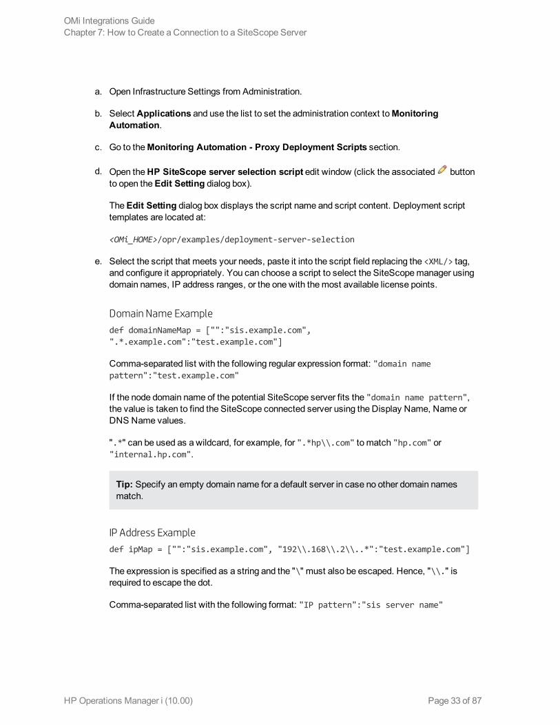
a. Open Infrastructure Settings from Administration.
b. Select Applications and use the list to set the administration context toMonitoringAutomation.
c. Go to theMonitoring Automation - Proxy Deployment Scripts section.
d. Open theHP SiteScope server selection script edit window (click the associated buttonto open theEdit Setting dialog box).
TheEdit Setting dialog box displays the script name and script content. Deployment scripttemplates are located at:
<OMi_HOME>/opr/examples/deployment-server-selection
e. Select the script that meets your needs, paste it into the script field replacing the <XML/> tag,and configure it appropriately. You can choose a script to select the SiteScopemanager usingdomain names, IP address ranges, or the one with themost available license points.
Domain Name Example
def domainNameMap = ["":"sis.example.com",".*.example.com":"test.example.com"]
Comma-separated list with the following regular expression format: "domain namepattern":"test.example.com"
If the node domain name of the potential SiteScope server fits the "domain name pattern",the value is taken to find the SiteScope connected server using the Display Name, Name orDNS Name values.
".*" can be used as a wildcard, for example, for ".*hp\\.com" to match "hp.com" or"internal.hp.com".
Tip: Specify an empty domain name for a default server in case no other domain namesmatch.
IP Address Example
def ipMap = ["":"sis.example.com", "192\\.168\\.2\\..*":"test.example.com"]
The expression is specified as a string and the "\" must also be escaped. Hence, "\\." isrequired to escape the dot.
Comma-separated list with the following format: "IP pattern":"sis server name"
OMi Integrations GuideChapter 7: How to Create a Connection to a SiteScope Server
HP Operations Manager i (10.00) Page 33 of 87
If the IP address of the potential SiteScope server fits the "IP pattern", the value is taken tofind the SiteScope connected server using the IP address of the system.
".*" can be used as a wildcard, for example, for "192\\.168\\.2.*" to match"192.168.2.10" or "192.168.204.88".
Tip: Specify an empty IP address for a default server in case no other IP addressesmatch.
f. Click Save.
OMi Integrations GuideChapter 7: How to Create a Connection to a SiteScope Server
HP Operations Manager i (10.00) Page 34 of 87

Part IV: Operations Manager i - HP OperationsManager Integration
HP Operations Manager i (10.00) Page 35 of 87

Chapter 8: Operations Manager i - HP OperationsManager Integration OverviewHP Operations Manager (HPOM) can be integrated into your OMi environment to become a data sourcefor OMi. HPOM forWindows, HPOM for UNIX (HP-UX and Solaris), and HPOM for Linux aresupported.
After you install both OMi and HPOM, follow the described procedures to connect OMi and HPOM.This connection enables bidirectional synchronization of events between the two systems, toolexecution, and instruction text retrieval. The connection configuration requires you to establish a trustrelationship between theOMi and HPOM systems, as well as to configure amessage forwardingpolicy.
The integration betweenOMi and HPOM provides you with the following capabilities:
l HPOM events > OMi. Events from HPOM are displayed in the OMi Event Browser.
l HPOM events > OMi health indicators. After you set up the integration, if the HPOM events havecorresponding health indicators defined, these health indicators automatically affect the status ofthe relevant Configuration Items (CIs) in OMi applications such as Service Health. For anintroduction to health indicators, see the OMi User Guide.
l OMi Actions, Tools, and Instructions. You can specify tools, for example, to ping a system.These tools are launched from events or the Actions panel and run on the associated CI. The toolsare designed to help users solve common problems quickly and efficiently. All available tools arelaunched in the context of a CI. The selection of tools a particular user sees in context menusdepends on the tools that are available for the CI affected by a particular event.
Events received in the OMi Event Browser may contain event-related actions configured in HPOM.If event-related actions exist, you can run these actions from theOMi console. HPOM actions canbe either operator-initiated, or can run automatically when an event occurs. For a complete overviewof available actions and how to run them, see theOMi online help.
Operators working with the HPOMmessage browser can see additional instructions for theselectedmessage. It is equally helpful for OMi operators to be able to access this information whenusing HPOM servers to forward events to OMi. This information is displayed in the Instructions tabof the Event Browser. For details, see the OMi User Guide.
l HPOM topology > RTSM topology. The HPOM topology can synchronize with the OMi RTSMtopology. Using topology synchronization, the HPOM services are synchronized with OMi, andusing correspondingmapping rules, they are transformed into CIs stored in the RTSM. For details,see the OMi Administration Guide.
Note: If the HPOM topology is not synchronized with the RTSM topology using the OMidynamic topology synchronizationmechanism, theMonitored by property of the OMi CIscorresponding to the HPOM services may be empty. As a consequence, these CIs are not
HP Operations Manager i (10.00) Page 36 of 87

displayed in the SystemMonitors only Perspective, System HardwareMonitoring, and SystemSoftwareMonitoring views.
OMi Integrations GuideChapter 8: Operations Manager i - HP Operations Manager Integration Overview
HP Operations Manager i (10.00) Page 37 of 87
Chapter 9: Workflow: Configuring ConnectionsBetween Operations Manager i and HPOM
1. Establish a trust relationship between OMi and HPOM
For connection and communication betweenOMi and HPOM hosts, establish a trust relationshipbetween all the servers.
For task details, see "How to Establish a Trust Relationship for a Server Connection" on page 39.
To verify the trusted relationship, see "How to Verify the Trusted Relationship" on page 43.
2. Set up the HPOM server as a connected server
Set up the HPOM server as a connected server so that you can run actions and tools from OMi,and retrieve instructions from the HPOM server.
For task details, see "How to Create a Connection to an HPOM Server" on page 44.
3. Synchronize the topology
To populate the OMi database (RTSM) with the configuration item (topology) and service datafrom HPOM, you need to synchronize the topology. Topology synchronization is configured toupdate all specified servers with the topology and service data from the HPOM server.
For task details, see "How to Run Dynamic Topology Synchronization" on page 48.
4. Configure the HPOM forwarding policy
To enable event synchronization between HPOM andOMi, set up amessage forwarding policy onthe HPOM server. The policy includes the node name of the target OMi server. Alternatively,specify the load balancers, if configured, or oneGateway Server for eachOMi installation, asappropriate for your high-availability arrangement.
n HPOM for Windows. For task details, see "How to Configure the HPOM forWindowsForwarding Policy" on page 53.
n HPOM for UNIX or Linux. For task details, see "How to Configure the HPOM for UNIX orLinux Forwarding Policy" on page 56.
5. Validate event synchronization
Validate event synchronization and test the connection between HPOM andOMi.
For task details, see "How to Validate Event Synchronization" on page 60.
HP Operations Manager i (10.00) Page 38 of 87
Chapter 10: How to Establish a Trust Relationship fora Server ConnectionFor connection and communication betweenOMi and HPOM hosts or other OMi hosts, youmustestablish a trust relationship between the systems.
In HPOM server pooling, the virtual server must have a certificate that is trusted by all HPOM hosts inthe server pool and by all OMi hosts.
Note: The trust relationship must be set up on all nodes (Data Processing Servers, GatewayServers, manager of manager configurations, load balancers, and reverse proxies). However,some load balancer technologies include a by-pass or pass-through functionality for incomingencryptedmessages to its pool members. When using such technologies, the trust relationship onthe load balancer node is not required if you are load balancing on the recommendedOSI layer 2 or4.
To establish a trust relationship between the Data Processing Servers and external serversystems:
1. On theOMi Data Processing Server, execute the following command:
BBCTrustServer[.bat|sh] <external_server>
Replace <external_server> with the FQDN of the external system (for example, hpommgmtsv).
Note: The value of <external_server> should be the virtual name in case of the HPOMserver pooling or high-availability (HA) cluster.
When asked if to add a certificate to the trust store, enter y.
If the trusted certificate already exists, the tool asks you if you want to overwrite the existingcertificate. To replace the existing certificate with a new one, enter y.
2. HPOM servers only:
Note:
HPOM for Windows:Starting with patches OMW_00121 (32-bit) andOMW_00122 (64-bit),theBBCTrustServer tool is already installed in the%OvInstallDir%\contrib\OVOW folder.
HP Operations Manager i (10.00) Page 39 of 87

HPOM for UNIX or Linux:Starting with HPOM server version 9.10.220, theBBCTrustServer tool is already installed in the /opt/OV/bin directory.
If you have the appropriate HPOM patch or version, you can skip this step.
a. Locate the following files on the OMi Data Processing Server:
<OMi_HOME>/opr/lib/cli/opr-cli.jar
<OMi_HOME>/opr/bin/BBCTrustServer.bat
<OMi_HOME>/opr/bin/BBCTrustServer.sh
b. HPOM forWindows only: Copy the files to themachine that is running the HPOM forWindows management server.
Copy opr-cli.jar to%OvInstallDir%\java\opr-cli.jar.
Copy BBCTrustServer.bat to%OvBinDir%\BBCTrustServer.bat.
c. HPOM for UNIX and Linux only: Copy the files to themachine that is running the HPOM forUNIX or Linux management server.
Copy opr-cli.jar to /opt/OV/java/opr-cli.jar.
Copy BBCTrustServer.sh to /opt/OV/bin/BBCTrustServer.sh.
Change the permissions of theBBCTrustServer tool by entering the following command:
chmod 555 /opt/OV/bin/BBCTrustServer.sh
3. If you do not have a load balancer or a reverse proxy, or your load balancer is configured to work onOSI layers 2 or 4 (recommended by HP), execute the following command on the externalsystem:
BBCTrustServer.[bat|sh] <load_balancer_or_single_gateway_server_or_RP_or_Server_Pool_Virtual_Interface>
When asked if to add a certificate to the trust store, enter y.
If the trusted certificate already exists, the tool asks you if you want to overwrite the existingcertificate. To replace the existing certificate with a new one, enter y.
4. If you are using a reverse proxy or your load balancer is configured to work onOSI layer 7, youmust exchange the certificates manually:
OMi Integrations GuideChapter 10: How to Establish a Trust Relationship for a Server Connection
HP Operations Manager i (10.00) Page 40 of 87
a. On theOMi Data Processing Server, execute the following command:
ovcert -exporttrusted -file <omi.cer>
b. On the external system, execute the following command:
ovcert -exporttrusted -file <other.cer>
c. Copy <other.cer> from the external system to the OMi Data Processing Server.
d. Copy <omi.cer> from theOMi Data Processing Server to the external system.
e. On theOMi Data Processing Server, execute the following commands:
ovcert -importtrusted -file <other.cer>
ovcert -importtrusted -file <other.cer> -ovrg server
f. On the external system, execute the following commands:
ovcert -importtrusted -file <omi.cer>
ovcert -importtrusted -file <omi.cer> -ovrg server
5. If you are using a load balancer or a reverse proxy, where your data sources are notcommunicating directly with the OMi Gateway Servers, make sure that port 383 is routed throughthe load balancer to the OMi Gateway Servers.
If the load balancer or the reverse proxy is configured to pass through traffic directly (OSI layers 2or 4), skip to the next step. If configured to work onOSI layer 7, perform as follows:
n The certificate on the load balancer must be installed for port 383 (or the port that youconfigured for secure communication).
n Communication between the load balancer and the gateway systems must be secured.
n The load balancer must possess a server certificate for authentication so that the externalsystems can connect successfully. The load balancer must also validate client certificatespresented by external clients (for example, HPOM servers).
n The load balancer must possess a client certificate for authentication with OMi.
a. Issue a certificate for the load balancer from theOMi Data Processing Server:
ovcm -issue -file <certificate file> -name <Fully Qualified Domain Name of VirtualInterface or Reverse Proxy> [ -pass <passphrase>]
b. Import this certificate as a server and client certificate into your load balancer.
OMi Integrations GuideChapter 10: How to Establish a Trust Relationship for a Server Connection
HP Operations Manager i (10.00) Page 41 of 87

For details on the required format, see your load balancer documentation. You can useopenssl to convert the certificates into the required format.
6. Check the connection between the servers. For details, see "How to Verify the TrustedRelationship" on page 43.
OMi Integrations GuideChapter 10: How to Establish a Trust Relationship for a Server Connection
HP Operations Manager i (10.00) Page 42 of 87
Chapter 11: How to Verify the Trusted RelationshipAfter establishing a trust relationship between theOMi Data Processing Server and external systems,check the connection between the two systems. You can do this while setting up your connectedserver in theServer Properties of theCreate New Server Connection dialog box by selectingTest Connection. You can also do this by using the command-line interface:
To check the connection between the OMi server environment and an external system:
1. From the external host, verify that communication to the OMi installation is possible (the returnvalue should be eServiceOk) by executing the following command on the external server system:
bbcutil -ping https://<load_balancer_or_single_gateway_server_or_RP_or_Server_Pool_Virtual_Interface>
Example of the command result:
https://<HP OMi servername>: status=eServiceOKcoreID=7c66bf42-d06b-752e-0e93-e82d1644cef8 bbcV=06.10.105appN=ovbbccb appV=11.03.031 conn=1 time=1094 ms
2. From all OMi Gateway Server hosts, verify that communication with the external server host ispossible (the return value should be eServiceOk) by executing the following command:
bbcutil -ping https://<external server hostname>
Example of the command result:
https://<external_host_server_name>: status=eServiceOKcoreID=0c43c032-5c94-7535-064a-f7654a86f2d3 bbcV=06.10.070appN=ovbbccb appV=11.03.031 conn=7 time=140 ms
Troubleshooting:
If the bbcutil –ping command executes but does not return eServiceOk, youmay need to restart theovc processes on the system that is not responding by running the following commands:
l Linux: /opt/OV/bin/ovc –kill and /opt/OV/bin/ovc –start
l Windows: ovc –kill and ovc –start
HP Operations Manager i (10.00) Page 43 of 87

Chapter 12: How to Create a Connection to an HPOMServerOMi can forward events, run actions and tools on the HPOM server, and retrieve instructions from theHPOM server. Credentials for the HPOMweb service are required for this processing.
1. In theConnected Servers pane, click New and select Operations Manager for Windows orOperations Manager for UNIX. TheCreate New Server Connection dialog box opens.
2. In theGeneral page, complete the following information:
a. Enter a display name, a unique internal name, if you want to replace the automaticallygenerated name, and (optional) a description of the connection being specified.
b. Select Active if you want to enable the server connection immediately.
c. Click Next to open theServer Properties page.
3. In theServer Properties page, complete the following information:
a. Enter the fully qualified DNS name of the host system of the HPOM server.
If the host system is a high-availability cluster, enter the fully qualified DNS name of thecluster package where the HPOM server is installed.
If HPOM is installed in a server pooling environment, add the virtual interface as the firstHPOM server. Add all physical pool servers separately as connected servers.
b. Enter the Integration User name used to log on to the HPOM server.
Note: All messages forwarded from HPOM systems are treated as allowing read andwrite. Any changes made to these events result in back synchronization to the originatingHPOM server.
For HPOM for Windows, the selected user must have at least PowerUser rights andmust be amember of the HP-OVE-Admins group and the local administrators group (forexample, HP-OVE-User).
For HPOM for UNIX or Linux, the Integration User must have HPOM administrator rights(for example, opc_adm) to be able to synchronize topology and execute tools.
c. Optional: Advanced Delivery Options It is possible to customize the way events andchange notifications are delivered to this server. The available options are:
HP Operations Manager i (10.00) Page 44 of 87
o Serial—Events and change notifications are delivered serially in the order that they werereceived.
o Serial per Source— (Default)Each originating server is provided with a dedicatedoutgoing request delivery path. For each individual outgoing request delivery path, eventsand change notifications are delivered serially in the order that they were received. Thiscan increase the throughput for delivery of events and change notifications whenmanyevents are received frommultiple originating servers, while maintaining the incomingorder.
o Parallel —The configured number of outgoing request delivery paths is used whenforwarding events and change notifications. This can further increase the throughput fordelivery of events and change notifications. However, because the source of the event isnot considered, maintenance of the incoming order cannot be guaranteed.
d. Specify if you want to forward dynamic topology information from theOMi instance to whichyou are logged on, to the HPOM instance that you are currently configuring.
Note:
If you change the status of the Forward Dynamic Topology to this Target Servercheck box, youmust restart theWDE process on all gateway servers. To do so, run thefollowing commands:
<OMi_HOME>/opr/support/opr-support-utils.[bat|sh] -stop wde
<OMi_HOME>/opr/support/opr-support-utils.[bat|sh] -start wde
e. Click Test Connection to check that the specified connection attributes are correct. If anerror link is displayed, check the error message, correct the connection information, and retestthe connection.
f. Click Next to open theOutgoing Connection page.
4. Outgoing Connection The outgoing connection is used to receive instructions, and execute toolsand actions on external nodes.
Note: If you edit outgoing connection properties (for example, integration user, password, andport), youmust restart theMercuryAS process for the changes to take effect.
Complete the following information:
n If you are using this server for receiving instructions, and executing tools and actions onexternal nodes, enter the password for the integration user and the port required to access theserver for receiving instructions, and executing tools and actions. The default port value is
OMi Integrations GuideChapter 12: How to Create a Connection to an HPOM Server
HP Operations Manager i (10.00) Page 45 of 87

automatically inserted and can be restored usingSet default port.
Note: For HPOM for Windows, the selected user must have at least PowerUser rights andmust be amember of the HP-OVE-Admins group and the local administrators group.
For HPOM for UNIX or Linux, the Integration User must have HPOM administrator rights(for example, opc_adm) to be able to synchronize topology and execute tools.
Optional: If you are using secure communication (default), make sure that theUse SecureHTTP option is selected, and apply a certificate using one of the followingmethods:
o Import from File—Opens the file browser and enables you to navigate to and specify aBase64 Encoded X.509 certificate file for the server connection.
o Retrieve from Server—Retrieve a certificate from the host system specified in thisserver connection.
Note: In a clustered HPOM for Windows environment, the IIS web server on all clusternodes must have the same certificate. If different, valid certificates are used, problemssuch as tools executionmay be experienced after switching to a node with a differentcertificate.
For more details, see the HP Software Self-solve knowledge base, article numberKM01211399, which can be accessed at:
http://h20230.www2.hp.com/selfsolve/document/KM01211399
Note: Secure communication is necessary for HPOM server pooling environments.However, do not use the Import from File or Retrieve from Server options.
Set up a trusted relationship between all HPOM andOMi servers as described in "How toEstablish a Trust Relationship for a Server Connection" on page 39.
n If you are using an alternative server for providing instructions, and executing actions andtools, select Use other Server, and then select a server from the list. For the physical serversin a server pooling environment, select the virtual interface connected server.
Note: Avoid selecting an alternative action execution server that creates a loop andresults in specifying the connected server as the action execution server. Select analternative action execution server or use theUse this Server option.
OMi Integrations GuideChapter 12: How to Create a Connection to an HPOM Server
HP Operations Manager i (10.00) Page 46 of 87
Click Test Connection to check that the specified connection attributes are correct. If an errorlink is displayed, check the error message, correct the connection information, and retest theconnection.
5. Click Finish.
6. If the HPOM server is connected to OMi using a load balancer, the URL of the load balancer(http://<load balancer>:80) must be specified in the infrastructure setting:
Foundation > Platform Administration > Host Configuration > Default Virtual GatewayServer for Data Collectors URL
Note: If you omit this setting, event synchronizationmight get confused as it is using thewrong sender hostname (the physical gateway server in place of the virtual system name).
OMi Integrations GuideChapter 12: How to Create a Connection to an HPOM Server
HP Operations Manager i (10.00) Page 47 of 87
Chapter 13: How to Run Dynamic TopologySynchronizationBefore configuring the forwarding of topology (node and service) data to OMi from HPOM servers,complete the following configuration steps in OMi:
l Establish a trust relationship between the Data Processing Server and the HPOM server. Fordetails, see "How to Establish a Trust Relationship for a Server Connection" on page 39.
l Add the HPOM server as a connected server to OMi. For details, see "How to Create a Connectionto an HPOM Server" on page 44.
l Optional. Import content packs. For details, see "Content Packs" in the OMi Administration Guide.
l Optional. Use the opr-sdtool.[bat|sh] command line tool to upload new or changedsynchronization packages from the file system to the database. For details, see the OMiExtensibility Guide.
Note: You can also use the Content Manager to import and export the existing synchronizationpackages in the Content Manager format.
After ensuring that the HPOM server is added to OMi as a connected server, configure the forwardingof topology (node and service) data on the HPOM server.
The following sections describe how to configure topology synchronization:
l "How to Configure Dynamic Topology Synchronization on HPOM forWindows Systems" below
l "How toMigrate from Scheduled Synchronization on HPOM forWindows Systems" on the nextpage
l "How to Configure Dynamic Topology Synchronization on HPOM for UNIX or Linux Systems" onpage 51
l "How toMigrate from Scheduled Synchronization on HPOM for UNIX or Linux Systems" onpage 51
How to Configure Dynamic Topology Synchronization on HPOM forWindows Systems
This section describes how to configure dynamic topology synchronization on HPOM forWindowsmanagement servers. For further details, see the HPOM forWindows documentation.
To forward topology data to OMi, complete the following steps on the HPOM for Windowsmanagement server from which you want to receive topology information:
HP Operations Manager i (10.00) Page 48 of 87
1. Prerequisite.Make sure that theminimum patch level for the HPOM forWindows managementserver is installed:
n Version 8.16: Patch OMW_00121 or superseding patch
n Version 9.00: Patch OMW_00122 or superseding patch
2. Prerequisite. Configure trusted certificates for multiple servers.
In an environment with multiple servers, youmust configure each server to trust certificates thatthe other servers issued.
3. In the console tree, right-click Operations Manager, and then click Configure > Server.... TheServer Configuration dialog box opens.
4. Click Namespaces, and then click Discovery Server. A list of values appears.
5. Add the hostname of the server to List of target servers to forward discovery data. If there ismore than one target server, separate the hostnames with semicolons, for example:
server1.example.com;server2.example.com
If the target server uses a port other than port 383, append the port number to the hostname, forexample:
server1.example.com:65530;server2.example.com:65531
6. Make sure that the value of Enable discovery WMI listener is true. This is the default value.
7. Click OK to save your changes and close the Server Configuration dialog box.
8. Restart the OvAutoDiscovery Server service for your changes to take effect:
net stop "OvAutoDiscovery Server"
net start "OvAutoDiscovery Server"
9. Start the initial synchronization of topology data:
a. In the console tree, select Tools > HP Operations Manager Tools.
b. Right-click Synchronize Topology and select All Tasks > Launch Tool....
The startInitialSync.bat tool is started and begins to send all the topology data to theconfigured target management servers.
How toMigrate from Scheduled Synchronization on HPOM forWindows Systems
This section describes how tomigrate from scheduled synchronization on HPOM forWindowsmanagement servers. For further details, see the HPOM forWindows documentation.
OMi Integrations GuideChapter 13: How to Run Dynamic Topology Synchronization
HP Operations Manager i (10.00) Page 49 of 87
To migrate from scheduled synchronization, complete the following steps on the HPOM forWindows management server from which you want to receive topology information:
1. Prerequisite.Make sure that theminimum patch level for the HPOM forWindows managementserver is installed:
n Version 8.16: Patch OMW_00121 or superseding patch
n Version 9.00: Patch OMW_00122 or superseding patch
2. Clear the agent repository cache on the HPOM management server using the following command:
%OvBinDir%\ovagtrep -clearall
3. Remove the service auto-discovery policies from the HPOM management server node:
%OvBinDir%\ovpolicy -remove DiscoverOM
%OvBinDir%\ovpolicy -remove DiscoverOMTypes
4. Synchronize the policy inventory on the HPOM management server:
a. In the console tree, right-click themanagement server.
b. Select All Tasks > Synchronize inventory > Policies.
Themanagement server creates a deployment job to retrieve the inventory from the localagent.
5. Make sure the listener process is running:
a. In the console tree, right-click Operations Manager, and select Configure Server.
The Server Configuration dialog box opens.
b. Click Namespaces, and select Discovery Server.
A list of values appears.
c. Set the value of Enable discovery WMI listener to true. This is the default value.
d. Click OK to save your changes and close the Server Configuration dialog box.
e. Restart the OvAutoDiscovery Server service for your changes to take effect:
net stop "OvAutoDiscovery Server"
net start "OvAutoDiscovery Server"
6. Start the initial synchronization of topology data:
OMi Integrations GuideChapter 13: How to Run Dynamic Topology Synchronization
HP Operations Manager i (10.00) Page 50 of 87

a. In the console tree, select Tools > HP Operations Manager Tools.
b. Right-click Synchronize Topology and select All Tasks > Launch Tool....
The startInitialSync.bat tool is started and begins to send all the topology data to theconfigured target servers.
How to Configure Dynamic Topology Synchronization on HPOM for UNIX or Linux Systems
This section describes how to configure dynamic topology synchronization on HPOM for UNIX or Linuxmanagement servers. For further details, see the HPOM for UNIX or Linux documentation.
To forward topology data to OMi, complete the following steps on the HPOM for UNIX orLinux management server from which you want to receive topology information:
1. Prerequisite.Make sure that your HPOM server version is 9.10.220 or higher.
2. Prerequisite. Configure trusted certificates for multiple servers.
In an environment with multiple servers, youmust configure each server to trust certificates thatthe other servers issued.
3. Prerequisite. Set up the forwarding target (OMi Gateway Server, Reverse Proxy, or LoadBalancer) in the node bank as amanaged node.
4. Type the following command to enable topology synchronization:
/opt/OV/contrib/OpC/enableToposync.sh -online -target <comma_separated_server_list>
Replace <comma_separated_server_list>with the fully qualified domain name of the targetmanagement server. If you havemore than one target management server, separate each servernamewith a comma (,). Do not include spaces in the server list.
This command restarts the service discovery server. The sourcemanagement server begins tosend any topology data changes immediately.
5. Type the following command to start the initial synchronization of topology data:
/opt/OV/bin/OpC/startInitialSync.sh
How toMigrate from Scheduled Synchronization on HPOM for UNIX or Linux Systems
This section describes how tomigrate from scheduled synchronization on HPOM for UNIX or Linuxmanagement servers. For further details, see the HPOM for UNIX or Linux documentation.
To migrate from scheduled synchronization, complete the following steps on the HPOM forUNIX or Linux management server from which you want to receive topology information:
OMi Integrations GuideChapter 13: How to Run Dynamic Topology Synchronization
HP Operations Manager i (10.00) Page 51 of 87
1. Prerequisite.Make sure that your HPOM server version is 9.10.220 or higher.
2. Clear the agent repository cache on themanagement server using the following command:
/opt/OV/bin/ovagtrep -clearall
3. Remove the service auto-discovery policies from themanagement server node:
/opt/OV/bin/ovpolicy -remove DiscoverOM
/opt/OV/bin/ovpolicy -remove DiscoverOMTypes
4. Deassign the service auto-discovery policies from themanagement server node:
/opt/OV/bin/OpC/utils/opcnode -deassign_pol node_name=<management_server> net_type=NETWORK_IP pol_name=DiscoverOMTypes pol_type=svcdisc
/opt/OV/bin/OpC/utils/opcnode -deassign_pol node_name=<management_server> net_type=NETWORK_IP pol_name=DiscoverOM pol_type=svcdisc
/opt/OV/bin/OpC/opcragt -dist <management_server>
Replace <management_server>with the name of themanagement server.
5. Type the following command to enable topology synchronization:
/opt/OV/contrib/OpC/enableToposync.sh -online
This command restarts the service discovery server. The sourcemanagement server begins tosend any topology data changes immediately.
6. Type the following command to start the initial synchronization of topology data:
/opt/OV/bin/OpC/startInitialSync.sh
OMi Integrations GuideChapter 13: How to Run Dynamic Topology Synchronization
HP Operations Manager i (10.00) Page 52 of 87

Chapter 14: How to Configure the HPOM for WindowsForwarding PolicyTo enable event synchronization between HPOM andOMi, set up amessage forwarding policy on theHPOM server. The policy includes the node name of the target OMi server. Alternatively, specify theload balancers, if configured, or oneGateway Server for eachOMi installation, as appropriate for yourhigh-availability arrangement.
Before setting up a policy and to avoid overwriting the current settings, verify if a policy of the typeServer-based Flexible Management is already active on the HPOM forWindows server. If a policydoes not exist, create a new policy as described in "Create a New Policy" below. If a policy alreadyexists and is active, adapt the policy as described in "Adapt an Active Policy" on the next page.
Create a New Policy
To set up a new policy on HPOM forWindows, complete the following steps:
1. Start the HPOM forWindows console as follows:
Start > Programs > HP > HP Operations Manager
2. In the left pane of the HPOM forWindows console, select the following:
Policy management > Policies grouped by type > Server Policies > Server-based FlexibleManagement
3. Verify that no Server-based Flexible Management policy exists. If such a policy does exist, go to"Adapt an Active Policy" on the next page.
4. Right-click Server-based Flexible Management (or a blank space in the right pane), and thenselect New > Policy.
The Server-based Flexible Management Editor dialog opens.
5. In theGeneral tab text pane, insert the following policy text:
TIMETEMPLATES# noneRESPMGRCONFIGS RESPMGRCONFIG DESCRIPTION "Forward all messages to OMi" SECONDARYMANAGERS ACTIONALLOWMANAGERS MSGTARGETRULES MSGTARGETRULE DESCRIPTION "Forward all messages rule" MSGTARGETRULECONDS MSGTARGETRULECOND DESCRIPTION "Forward all messages"
HP Operations Manager i (10.00) Page 53 of 87
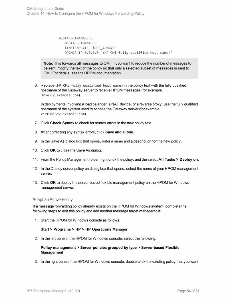
MSGTARGETMANAGERS MSGTARGETMANAGER TIMETEMPLATE "$OPC_ALWAYS" OPCMGR IP 0.0.0.0 "<HP OMi fully qualified host name>"
Note: This forwards all messages to OMi. If you want to reduce the number of messages tobe sent, modify the text of the policy so that only a selected subset of messages is sent toOMi. For details, see the HPOM documentation.
6. Replace <HP OMi fully qualified host name> in the policy text with the fully qualifiedhostname of the Gateway server to receive HPOMmessages (for example,HPGwSrv.example.com).
In deployments involving a load balancer, a NAT device, or a reverse proxy, use the fully qualifiedhostname of the system used to access the Gateway server (for example,VirtualSrv.example.com).
7. Click Check Syntax to check for syntax errors in the new policy text.
8. After correcting any syntax errors, click Save and Close.
9. In the Save As dialog box that opens, enter a name and a description for the new policy.
10. Click OK to close the Save As dialog.
11. From the Policy Management folder, right-click the policy, and the select All Tasks > Deploy on.
12. In the Deploy server policy on dialog box that opens, select the name of your HPOMmanagementserver.
13. Click OK to deploy the server-based flexible management policy on the HPOM forWindowsmanagement server.
Adapt an Active Policy
If a message forwarding policy already exists on the HPOM forWindows system, complete thefollowing steps to edit this policy and add another message target manager to it:
1. Start the HPOM forWindows console as follows:
Start > Programs > HP > HP Operations Manager
2. In the left pane of the HPOM forWindows console, select the following:
Policy management > Server policies grouped by type > Server-based FlexibleManagement
3. In the right pane of the HPOM forWindows console, double-click the existing policy that you want
OMi Integrations GuideChapter 14: How to Configure the HPOM forWindows Forwarding Policy
HP Operations Manager i (10.00) Page 54 of 87

to edit. The Server-based Flexible Management Editor dialog opens.
If such a policy does not exist, go to "Create a New Policy" on page 53.
4. Add another message target manager as shown in the following example policy text:
TIMETEMPLATES# noneRESPMGRCONFIGS RESPMGRCONFIG DESCRIPTION "Forward all messages to OMi" SECONDARYMANAGERS ACTIONALLOWMANAGERS MSGTARGETRULES MSGTARGETRULE DESCRIPTION "Forward all messages rule" MSGTARGETRULECONDS MSGTARGETRULECOND DESCRIPTION "Forward all messages" MSGTARGETMANAGERS MSGTARGETMANAGER TIMETEMPLATE "$OPC_ALWAYS" OPCMGR IP 0.0.0.0 "<First Target Manager>"
MSGTARGETMANAGER TIMETEMPLATE "$OPC_ALWAYS" OPCMGR IP 0.0.0.0 "<HP OMi fully qualified host name>"
Note: This forwards all messages to OMi. If you want to reduce the number of messages tobe sent, modify the text of the policy so that only a selected subset of messages is sent toOMi. For details, see the HPOM documentation.
5. Replace <HP OMi fully qualified host name> in the text with the fully qualified hostname ofthe Gateway server that should receive HPOMmessages (for example, HPGwSrv.example.com).
In deployments involving a load balancer, a NAT device, or a reverse proxy, use the fully qualifiedhostname of the system used to access the Gateway server (for example,VirtualSrv.example.com).
6. Click Check Syntax to check for syntax errors in the new policy text.
7. After correcting any syntax errors, click Save and Close.
8. Redeploy the server-based flexible management policy on the HPOM forWindows managementserver.
OMi Integrations GuideChapter 14: How to Configure the HPOM forWindows Forwarding Policy
HP Operations Manager i (10.00) Page 55 of 87
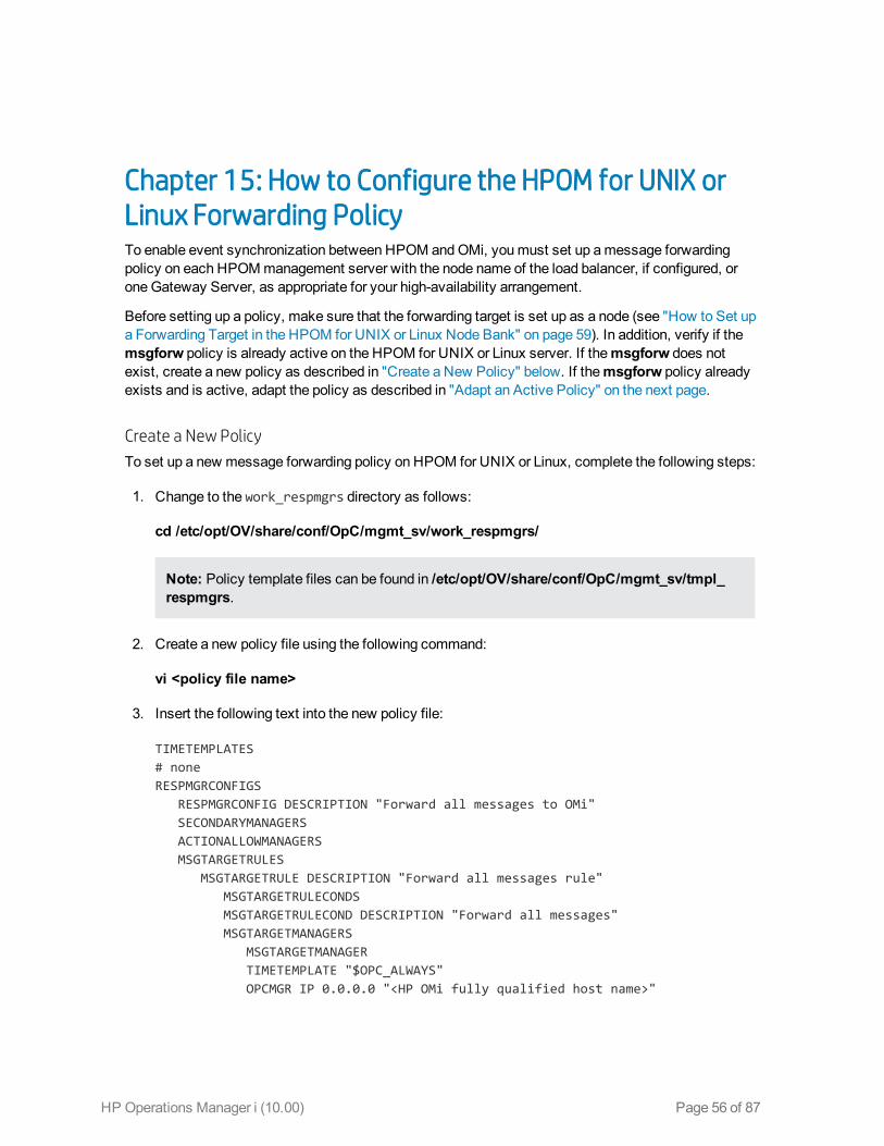
Chapter 15: How to Configure the HPOM for UNIX orLinux Forwarding PolicyTo enable event synchronization between HPOM andOMi, youmust set up amessage forwardingpolicy on each HPOMmanagement server with the node name of the load balancer, if configured, oroneGateway Server, as appropriate for your high-availability arrangement.
Before setting up a policy, make sure that the forwarding target is set up as a node (see "How to Set upa Forwarding Target in the HPOM for UNIX or Linux Node Bank" on page 59). In addition, verify if themsgforw policy is already active on the HPOM for UNIX or Linux server. If themsgforw does notexist, create a new policy as described in "Create a New Policy" below. If themsgforw policy alreadyexists and is active, adapt the policy as described in "Adapt an Active Policy" on the next page.
Create a New Policy
To set up a new message forwarding policy on HPOM for UNIX or Linux, complete the following steps:
1. Change to the work_respmgrs directory as follows:
cd /etc/opt/OV/share/conf/OpC/mgmt_sv/work_respmgrs/
Note: Policy template files can be found in /etc/opt/OV/share/conf/OpC/mgmt_sv/tmpl_respmgrs.
2. Create a new policy file using the following command:
vi <policy file name>
3. Insert the following text into the new policy file:
TIMETEMPLATES# noneRESPMGRCONFIGS RESPMGRCONFIG DESCRIPTION "Forward all messages to OMi" SECONDARYMANAGERS ACTIONALLOWMANAGERS MSGTARGETRULES
MSGTARGETRULE DESCRIPTION "Forward all messages rule" MSGTARGETRULECONDS MSGTARGETRULECOND DESCRIPTION "Forward all messages" MSGTARGETMANAGERS MSGTARGETMANAGER TIMETEMPLATE "$OPC_ALWAYS" OPCMGR IP 0.0.0.0 "<HP OMi fully qualified host name>"
HP Operations Manager i (10.00) Page 56 of 87

Note: This forwards all messages to OMi. If you want to reduce the number of messages tobe sent, modify the text of the policy so that only a selected subset of messages is sent toOMi. For details, see the HPOM documentation.
4. Replace <HP OMi fully qualified host name> in the text with the fully qualified hostname ofthe Gateway server that should receive HPOMmessages (for example, HPGwSrv.example.com).
In deployments involving a load balancer, a NAT device, or a reverse proxy, use the fully qualifiedhostname of the system used to access the Gateway server (for example,VirtualSrv.example.com).
5. Enter the following command to check for syntax errors in the new policy text:
/opt/OV/bin/OpC/opcmomchk -msgforw <policy file name>
6. After correcting any syntax errors, copy the policy to themsgforw policy file in the respmgrsdirectory as follows:
cp <policy file name> /etc/opt/OV/share/conf/OpC/mgmt_sv/respmgrs/msgforw
7. Inform the server processes to reread the configuration as follows:
/opt/OV/bin/ovconfchg
Message forwarding from HPOM toOMi is now configured and enabled.
Adapt an Active Policy
If themessage forwarding policy already exists on the HPOM for UNIX or Linux system, complete thefollowing steps to edit this policy and add another message target manager to it:
1. Change to the work_respmgrs directory as follows:
cd /etc/opt/OV/share/conf/OpC/mgmt_sv/work_respmgrs/
Note: Policy template files can be found in /etc/opt/OV/share/conf/OpC/mgmt_sv/tmpl_respmgrs/.
2. Edit the existing policy to which you want to add theOMi server as a target as follows:
vi <policy file name>
3. Add another message target manager as shown in the following policy text:
# noneRESPMGRCONFIGS
OMi Integrations GuideChapter 15: How to Configure the HPOM for UNIX or Linux Forwarding Policy
HP Operations Manager i (10.00) Page 57 of 87

RESPMGRCONFIG DESCRIPTION "Forward all messages to OMi" SECONDARYMANAGERS ACTIONALLOWMANAGERS MSGTARGETRULES MSGTARGETRULE DESCRIPTION "Forward all messages rule" MSGTARGETRULECONDS MSGTARGETRULECOND DESCRIPTION "Forward all messages" MSGTARGETMANAGERS MSGTARGETMANAGER TIMETEMPLATE "$OPC_ALWAYS" OPCMGR IP 0.0.0.0 "<First Target Manager>"
MSGTARGETMANAGER TIMETEMPLATE "$OPC_ALWAYS" OPCMGR IP 0.0.0.0 "<HP OMi fully qualified host name>"
Note: This policy forwards all messages to OMi. If you want to reduce the number ofmessages to be sent, modify the text of the policy so that only a selected subset ofmessages is sent to OMi. For details, see the HPOM documentation.
4. Replace <HP OMi fully qualified host name> in the text with the fully qualified hostname ofthe Gateway Server system that should receive HPOMmessages (for example,HPGwSrv.example.com).
In deployments involving a load balancer, a NAT device, or a reverse proxy, use the fully qualifiedhostname of the system used to access the Gateway Server system (for example,VirtualSrv.example.com).
5. Enter the following command to check for syntax errors in the new policy text:
/opt/OV/bin/OpC/opcmomchk -msgforw <policy file name>
6. After correcting any syntax errors, copy the policy to themsgforw policy file in the respmgrsdirectory as follows:
cp <policy file name> /etc/opt/OV/share/conf/OpC/mgmt_sv/respmgrs/msgforw
7. Inform the server processes to reread the configuration as follows:
/opt/OV/bin/ovconfchg
Message forwarding from HPOM toOMi is now configured and enabled.
OMi Integrations GuideChapter 15: How to Configure the HPOM for UNIX or Linux Forwarding Policy
HP Operations Manager i (10.00) Page 58 of 87
Chapter 16: How to Set up a Forwarding Target in theHPOM for UNIX or Linux Node Bank
Note: Make sure that the SNMP agent is running before adding amanaged node to the HPOMdatabase.
The forwarding target (OMi Gateway Server, Reverse Proxy, or Load Balancer) must be set up in thenode bank as amanaged node. Youmust add themanaged node by using the opcnode command linetool, for example:
/opt/OV/bin/OpC/utils/opcnode -add_node node_name=<node_name> net_type=NETWORK_IPmach_type=<machine_type> group_name=<group_name> node_label=<node_name>
In this instance, <machine_type> relates to the operating system of the OMi host system, MACH_BBC_WIN2K3_X64 (Windows) or MACH_BBC_LX26RPM_X64 (Linux), whereas <group_name> relates to theoperating system of the HPOM server host system, hp_ux, solaris, or linux.
To verify that the node was added successfully, run the following command:
/opt/OV/bin/OpC/utils/opcnode -list_nodes
HP Operations Manager i (10.00) Page 59 of 87

Chapter 17: How to Validate Event SynchronizationThis chapter provides you with instructions on how to validate event synchronization and test theconnection between HPOM andOMi.
Note: Make sure that you configured HPOM to enable OMi users to use tools, actions, andinstruction text. You configure this in the Connected Servers manager in OMi. For details, see"How to Create a Connection to an HPOM Server" on page 44.
Verify Message Forwarding from HPOM to OMi
To check if themessage forwarding policy for sendingmessages from HPOM toOMi is configuredcorrectly, follow these steps:
1. Make sure the OMi servers are running.
2. Make sure at least one openmessage interface policy is deployed on your HPOM system. Forinstructions and details, see the HPOM documentation.
3. On the HPOM system, open a command or shell prompt and create a new message by executingthe following command:
n Windows:
opcmsg a=App o=Obj msg_text="Hello"
n UNIX or Linux:
/opt/OV/bin/OpC/opcmsg a=App o=Obj msg_text="Hello"
If you configured themessage forwarding policy correctly, themessage arrives at the HPOMserver and is forwarded to OMi. You can view the events with the OMi Event Browser.
Note: If themessage is sent multiple times, no new message is generated by HPOM. Thesemessages are regarded as duplicates and only themessage duplicate count is increased.
To generate a new message, modify themessage text. For example:
n Windows:
opcmsg a=App o=Obj msg_text="Hello_002"
n UNIX or Linux:
/opt/OV/bin/OpC/opcmsg a=App o=Obj msg_text="Hello_002"
HP Operations Manager i (10.00) Page 60 of 87
Synchronize OMi Events with HPOMMessages
To check if a change to an event in OMi that is already synchronized betweenOMi and HPOM isresynchronized in HPOM, change the severity of an event as follows:
1. Make sure the OMi platform is running.
2. Log on to the OMi platform management console.
3. Select Applications > Operations Management.
4. In the Event Browser, select the event for which you want to change the severity. Choose theevent that was already synchronized in HPOM andOMi and change its severity, for example, fromminor to major.
5. Access the General tab of the Event Details pane.
6. From the Severity drop-down list, choose another severity (for example, major), and then clickSave.
7. In the HPOM event browser, verify the severity of this event andmake sure it was set to the newseverity value.
OMi Integrations GuideChapter 17: How to Validate Event Synchronization
HP Operations Manager i (10.00) Page 61 of 87

Chapter 18: How to Set up Operations Manager i in anEnvironment Managed by HPOMTo set upOMi in an environment managed by HPOM, follow these steps:
1. Before installing OMi, on all Data Processing Servers andGateway Servers, run the followingcommand:
ovconfchg -ns sec.cm.client -set CERTIFICATE_SERVER <FQDN of primary DPS>
2. Install and configure OMi according to the OMi Installation and UpgradeGuide.
3. Integrate HPOM as described in "Workflow: Configuring Connections BetweenOperationsManager i and HPOM" on page 38.
HP Operations Manager i (10.00) Page 62 of 87
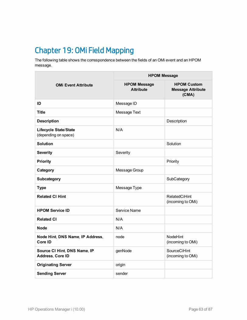
Chapter 19: OMi Field MappingThe following table shows the correspondence between the fields of an OMi event and an HPOMmessage.
OMi Event Attribute
HPOM Message
HPOM MessageAttribute
HPOM CustomMessage Attribute
(CMA)
ID Message ID
Title Message Text
Description Description
Lifecycle State/State(depending on space)
N/A
Solution Solution
Severity Severity
Priority Priority
Category MessageGroup
Subcategory SubCategory
Type Message Type
Related CI Hint RelatedCiHint(incoming to OMi)
HPOM Service ID Service Name
Related CI N/A
Node N/A
Node Hint, DNS Name, IP Address,Core ID
node NodeHint(incoming to OMi)
Source CI Hint, DNS Name, IPAddress, Core ID
genNode SourceCiHint(incoming to OMi)
Originating Server origin
Sending Server sender
HP Operations Manager i (10.00) Page 63 of 87
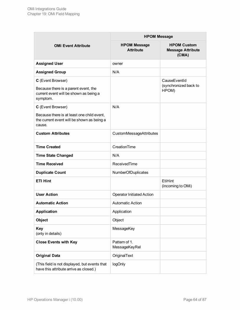
OMi Event Attribute
HPOM Message
HPOM MessageAttribute
HPOM CustomMessage Attribute
(CMA)
Assigned User owner
Assigned Group N/A
C (Event Browser)
Because there is a parent event, thecurrent event will be shown as being asymptom.
CauseEventId(synchronized back toHPOM)
C (Event Browser)
Because there is at least one child event,the current event will be shown as being acause.
N/A
Custom Attributes CustomMessageAttributes
Time Created CreationTime
Time State Changed N/A
Time Received ReceivedTime
Duplicate Count NumberOfDuplicates
ETI Hint EtiHint(incoming to OMi)
User Action Operator Initiated Action
Automatic Action Automatic Action
Application Application
Object Object
Key(only in details)
MessageKey
Close Events with Key Pattern of 1.MessageKeyRel
Original Data OriginalText
(This field is not displayed, but events thathave this attribute arrive as closed.)
logOnly
OMi Integrations GuideChapter 19: OMi Field Mapping
HP Operations Manager i (10.00) Page 64 of 87
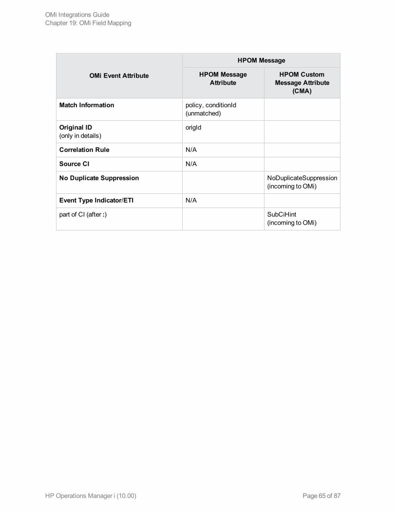
OMi Event Attribute
HPOM Message
HPOM MessageAttribute
HPOM CustomMessage Attribute
(CMA)
Match Information policy, conditionId(unmatched)
Original ID(only in details)
origId
Correlation Rule N/A
Source CI N/A
No Duplicate Suppression NoDuplicateSuppression(incoming to OMi)
Event Type Indicator/ETI N/A
part of CI (after :) SubCiHint(incoming to OMi)
OMi Integrations GuideChapter 19: OMi Field Mapping
HP Operations Manager i (10.00) Page 65 of 87
Chapter 20: TroubleshootingThis section contains troubleshooting information about HPOM integration-related issues.
Cleanup after switching HPOM to another OMi server
After reconnecting HPOM to another OMi server, for example after activating a disaster recoveryenvironment, you should delete the bufferedmessages on the HPOM system for the old OMi server. Ifthemessages are left in the forwarding buffer, theremay be some performance degradation as thesystem regularly tries to deliver them without success. They also consume some disk space. It is notpossible to re-direct thesemessages to the new OMi server, and these cannot be synchronized.
Note: All messages currently in the buffer are deleted. It is not possible to distinguish betweendifferent targets andmessages for other targets are also deleted.
To delete the forwarding buffer files on HPOM for Windows:
1. Stop the server processes: vpstat -3 -r STOP
2. Delete all files and folders contained within the following directories:
<OvDataDir>\shared\server\datafiles\bbc\snf\data
<OvDataDir>\shared\server\datafiles\bbc\snf\OvEpMessageActionServer
3. Restart the server processes: vpstat -3 -r START
To delete the forwarding buffer files on HPOM for UNIX:
1. Stop the server processes: ovc -kill
2. Delete all files and folders contained within the following directories:
/var/opt/OV/shared/server/datafiles/bbc/snf/data
/var/opt/OV/share/tmp/OpC/mgmt_sv/snf/opcforwm
3. Restart the server processes: ovc -start
HP Operations Manager i (10.00) Page 66 of 87
HP Operations Manager i (10.00) Page 67 of 87
Part V: Operations Manager i - Network NodeManager i Integration
Chapter 21: Operations Manager i - Network NodeManager i Integration Overview
Tip: The following is a high-level overview of the Operations Manager i - Network NodeManager i(NNMi) integration. You can find comprehensive details on NNMi integrations in theHP NetworkNodeManager i Software—HP Business ServiceManagement/Universal CMDB TopologyIntegration Guide.
You can integrate NNMi with OMi to provide the following capabilities:
l NNMi topology > OMi RTSM topology. The topology integration populates the OMi RTSMwiththe NNMi network topology. OMi stores each device, interface, IP address, and a few otherartifacts in the NNMi network topology as a CI and includes it in the relevant views.
l NNMi events > OMi events. NNMi events are displayed in the Event Browser in OMi. You canalso access the NNMi console from theOMi Event Browser. The NNMi events are sent to OMiusing the BSMConnector.
This integration has item ID 344 in the Integrations Catalog at the following location:
http://support.openview.hp.com/sc/solutions/integrations.jsp?intid=344
l NNMi events > OMi health indicators. After you have set up the integration, if the NNMi eventshave corresponding health indicators defined, these health indicators affect the status of relevantCIs in OMi applications, such as Service Health.
l OMi > NNMi drilldown. In OMi, you can configure a link to the NNMi management server thatenables you to drill down fromMy Workspace and other locations to NNMi, to view trace routeinformation between the client and the destinationmachine. You can also use URL tools to launch abrowser that enables you to connect to the NNMi management server and further analyze incomingevents in NNMi.
In addition, certain NNMi user interface components (network maps, items, detailed informationdialogs, and so on) can be displayed directly inWorkspaces > My Workspace.
Note: If the NNMi topology is not synchronized with the OMi RTSM topology, theMonitored byproperty of the OMi CIs corresponding to the NNMi CIs is empty, and these CIs are not displayedin the SystemMonitors only Perspective, System HardwareMonitoring, and System SoftwareMonitoring views.
HP Operations Manager i (10.00) Page 68 of 87

Chapter 22: How to Integrate Network Node Manager iwith Operations Manager iThis chapter describes how to integrate NNMi with OMi.
1. Prerequisite
Make sure you have theOMi and NNMi licenses installed. For details, see the OMi AdministrationGuide.
2. Perform the integration in NNMi
Perform the steps needed to integrate NNMi with OMi in the NNMi application.
For details, see theHP Network NodeManager i Software—HP Business ServiceManagement/Universal CMDB Topology Integration Guide.
3. Configure LW-SSO in both OMi and NNMi (Optional)
To be able to seamlessly switch between NNMi andOMi, it is recommended to use LW-SSO.Make sure that LW-SSO is configured in both OMi and NNMi with the same initString. For detailson how to configure the initString in OMi, see the OMi Administration Guide. For details on how toconfigure the initString in NNMi, see theNNMi Deployment Reference.
It is also possible to integrate NNMi with OMi without using LW-SSO. In this case, you areprompted for a password every time you switch to an NNMi component.
4. Connect NNMi tomore than one OMi instance
After connecting the first OMi instance to NNMi, NNMi stores in its own database the CI IDsgained from the topology synchronization of the OMi's RTSM. When another OMi instance isconnected, another topology synchronization is carried out. As the OMi instances might containsome of the sameCI IDs, the IDs need to be reconciled in the NNMi database. This reconciliationworks only partially and the NNMi log files still include several reconciliation errors that are causedby the non-existing RTSM IDs. To fix the problem, perform the following steps:
a. Change the integration to the new OMi system.
b. Log on to the NNMi JMX console http://<NNMi_fqdn_and_port>/jmx-console using thesystem account and password.
c. Go tombean NnmBsmModule.
d. Run java.lang.String resetNnmBsmIds().
HP Operations Manager i (10.00) Page 69 of 87
You should see a list of devices from which the RTSM ID was removed.
e. Disable and enable the topology integration to get the CIs into RTSM.
5. Configure OMi to display NNMi data
To display NNMi data in OMi and to access the NNMi components inWorkspaces > MyWorkspace:
a. Open Infrastructure Settings:
Administration > Setup and Maintenance > Infrastructure Settings
Alternatively, click Infrastructure Settings.
b. Select Foundations.
c. Select Integrations with other applications.
d. In the Integrations with other applications - HP NNM table, locate andmodify thefollowing parameters:
o HP NNM Integration URL. The NNMi host and port number (protocol://host:port/nnm).
o HP NNM User name. The user name that is used for logging on to NNMi.
o HP NNM User password. The user password that is used for logging on to NNMi.
6. Results
You can view NNMi data inWorkspaces > My Workspace, as described in "NNMi Componentsin My Workspace" on page 71.
OMi Integrations GuideChapter 22: How to Integrate Network NodeManager i with Operations Manager i
HP Operations Manager i (10.00) Page 70 of 87
Chapter 23: NNMi Components in MyWorkspaceIf you set up an integration between NNMi andOMi, you can view the NNMi components describedbelow inWorkspaces > My Workspace as follows:
1. Click theNew Page icon.
2. Click Add Component. The Component Gallery window opens.
3. In All Categories, select theNNMi check box.
To access the NNMi components, youmust have the appropriate licenses installed. NNMicomponents are only displayed if you configured a connection to an NNMi server in InfrastructureSettings:
Administration > Setup and Maintenance > Infrastructure Settings
Alternatively, click Infrastructure Settings.
Select Foundations > Integrations with other applications > HP NNM.
ComponentName Description
Layer 2NeighborView
Shows amap view of a selected device and its connector devices within aspecified number of hops from the selected device. This view is useful forunderstanding the switch connectivity between devices.
Layer 3NeighborView
Shows amap view of a selected device and its connector devices within aspecified number of hops from the selected device. This view is useful forunderstanding the router connectivity between devices.
MPLS VPNInventory
This is an enterprise customer view of how their sites are connected via serviceprovidedMPLS networks.
Open KeyIncidents
Shows the incidents that aremost important to network operators and that oftenrequire more immediate action.
OverallNetworkHealth (NodeGroupOverview)
Displays amap containing all (top-level) NodeGroups that do not have parent NodeGroups.
OverallNetworkHealth -Routers
Displays a NodeGroupMap of the Router connectivity in your network.
HP Operations Manager i (10.00) Page 71 of 87

ComponentName Description
OverallNetworkHealth -Switches
Displays a NodeGroupmap of the Switches connectivity in your network.
RouterRedundancyGroupsInventory
Shows the available Router Redundancy Groups created by the NNMiadministrator. Each Router Redundancy Group is a set of two or more routers thatuse one or more virtual IP addresses to help ensure that information packets reachtheir intended destination.
OMi Integrations GuideChapter 23: NNMi Components in My Workspace
HP Operations Manager i (10.00) Page 72 of 87

HP Operations Manager i (10.00) Page 73 of 87
Part VI: Operations Manager i - OperationsOrchestration Integration
Chapter 24: Operations Manager i - OperationsOrchestration Integration OverviewHP Operations Orchestration (OO) provides a simple way for customers to run scripts for automaticactions. The integration with OMi uses the OO capabilities for building investigation tools or serviceremediation scripts, providing the operators with a simple way to validate a problem, investigate it, orautomatically correct it. A run book can be executedmanually.
OO run books can be launched from the Service Health and Event Browser applications.
The integration of OMi andOO provides the capability of mapping CI types to OO run books.
After you create suchmappings, you can run themappedOO run books:
l On CIs, using the Invoke Run Books context menu option in Service Health. TheOO runbook parameters are populated using themap to the CI attributes defined in the Run Book MappingConfiguration wizard. For detailed information about the wizard, see the OMi Administration Guide.
l At the event level. OMi opens an event and checks if the CI for this event has a run book assignedto it, and if the run book is set to run automatically. TheOO run book parameters are populatedusing themap to the CI or event attributes defined in the Run Book Mapping Configuration wizard.For detailed information about the wizard, see the OMi Administration Guide.
HP Operations Manager i (10.00) Page 74 of 87

Chapter 25: How to Integrate Operations Manager iand Operations OrchestrationThis chapter describes how to integrate OMi andOO.
1. Prerequisites
Before you configure the integration, the OO administrator needs to perform the following:
a. Enable user authentication and create an integration user with theAdministrator role:
o OO version 10.02 or higher: The user must be internal.
o OO 9.xx: The user must be external.
Users must have the following capabilities in OO: AUTHOR, SCHEDULE, MANAGE_RUNS, RUN_REPORTS, and HEADLESS_FLOWS. You can either add users to groupswith these capabilities (for example, the administrator group has these capabilities) or youcan create such a group.
b. Deploy the following OOContent Packs (CPs) on the OO server: Base,Middleware, andOperating Systems.
First deploy theBaseCP, and then the other CPs.
For details how to deploy CPs in OO, see theOO documentation.
2. Configure the link between OMi and OO
To configure the integration betweenOMi andOO, in OMi:
a. Open Infrastructure Settings:
Administration > Setup and Maintenance > Infrastructure Settings
Alternatively, click Infrastructure Settings.
b. Select Foundations.
c. Select Integrations with other applications.
d. In theHP Operations Orchestration table, locateOperations Orchestration applicationURL, andmodify the setting to the URL used to access the OO application.
When connecting anOMi instance that employs Lightweight Single Sign-On (LW-SSO) toOOversion 10.02 or higher, youmust specify the connection URL of OO using the followingformat: <protocol>://<FQDN>:<portNumber> (for example, http://lab.lab:8080). The port
HP Operations Manager i (10.00) Page 75 of 87
can be 8080 for HTTP or 8443 for HTTPS, according to your needs. ForOO 9.xx, use:https://<fully qualified server name>:8443.
If you want to enable run books to be invoked automatically, youmust enter a User Name andPassword in the same table. In this case, the user should be defined as internal in OO.
e. OO 9.xx only: To be able to invoke run books automatically, the user must be internal.
3. Configure LW-SSO authentication
Configure LW-SSO authentication betweenOMi andOO. Youmust configure LW-SSO in bothOMi andOO. Proceed to the relevant section depending on your version of OO.
For OO version 9.05 or lower:
a. In OMi, open AuthenticationManagement:
Administration > Users > Authentication Management
Alternatively, click AuthenticationManagement.
Copy the Token Creation Key (initString) to OO, and replace, in OO, all the initStrings in thelwssofmconf.xml file located in the <OO installation directory>\Program Files\Hewlett-Packard\Operations Orchestration\Central\conf\ directory.
b. In OO, in theweb.xml and applicationContext.xml files located in the<OO installation directory>\Program Files\Hewlett-Packard\Operations Orchestration\Central\WEB-INF\ directory, enable all filters andmappingsbetween LWSSO_SECTION_BEGIN and LWSSO_SECTION_END.
c. If OO andOMi are in different domains in theWindows operating system, youmust make surethat the Trusted Hosts/Domains parameter is the same in OO andOMi. To set theparameter in OMi, open AuthenticationManagement:
Administration > Users > Authentication Management
Alternatively, click AuthenticationManagement.
Configure the Trusted Hosts/Domains parameter.
d. Restart the following OO services:
o For OO version 9.02 or lower: RSCentral, RSJRAS, andRSScheduler.
o For OO version 9.03, 9.04, or 9.05: RSCentral andRSJRAS.
Note: If you need to enable logging for debugging LW-SSO: In OO, in the <OO installationdirectory>\jetty\resources\log4j.properties file, uncomment the line that appears under the
OMi Integrations GuideChapter 25: How to Integrate Operations Manager i andOperations Orchestration
HP Operations Manager i (10.00) Page 76 of 87
LW-SSO comment.
For OO version 9.06 or higher:
a. In OMi, open AuthenticationManagement:
Administration > Users > Authentication Management
Alternatively, click AuthenticationManagement.
Copy the Token Creation Key (initString).
b. In OO, access the following:
o For OO version 10.20, select System Configuration > Security > SSO.
o For OO version 10.02 or higher (except version 10.20), select System Workspace >Security > SSO.
o For OO version 9.xx, select Administration > System Configuration >Authentication.
c. In the LW SSO Settings area, select theEnable check box.
d. Replace the value of the LW SSO passphrase or the InitString parameter with the TokenCreation Key you copied from OMi. (This must have the same value on all OMi instances thatare integrated using LW-SSO.)
e. Define domain-related parameters in the LW SSO Settings area:
o Domain. The domain of the OO server.
o Protected Domains. List of comma-separated domains used by the OMi instances thatemploy LW-SSO.
Note: If OO andOMi are in different domains in theWindows operating system, makesure that the Trusted Hosts/Domains parameter is the same in OO andOMi.
In OMi, open AuthenticationManagement:
Administration > Users > Authentication Management
Alternatively, click AuthenticationManagement.
Configure the Trusted Hosts/Domains parameter.
OMi Integrations GuideChapter 25: How to Integrate Operations Manager i andOperations Orchestration
HP Operations Manager i (10.00) Page 77 of 87

Note: Limitation with OO 10.02 or higher and OMi
The integration of OO 10.02 or higher with OMi is currently only supported if OO andOMi arein the same domain. If they are in different domains, the integration fails.
For further details on configuring LW-SSO in OO, see theOO documentation.
For further details on configuring LW-SSO in OMi, see the OMi Administration Guide.
4. Export server certificates from OO
To export server certificates from OO and import them into OMi in aWindows or Linuxenvironment, use the keytool utility, which is included in Sun JRE.
For OO 9.xx:
a. On theOO server, enter:
o Windows:
[OO install folder]\jre1.6\bin\keytool -keystore "[OO install folder]\Central\conf\rc_keystore" -export -alias pas -file "<path>\<Operations Orchestration fully qualifiedhost name>.cer"
o Linux:
keytool -keystore "$ICONCLUDE_HOME/Central/conf/rc_keystore" -export -aliaspas -file "<path>/<Operations Orchestration fully qualified host name>.cer"
b. When prompted for a password, enter bran507025.
For OO version 10.02 or higher
a. On theOO server, enter:
o Windows:
[OO install folder]\java\bin\keytool.exe -keystore "[OO install folder]\central\var\security\key.store" -export -alias tomcat -file "<path>\<OperationsOrchestration fully qualified host name>.cer"
o Linux:
keytool -keystore "$ICONCLUDE_HOME/central/var/security/key.store" -export -alias tomcat -file "<path>/<Operations Orchestration fully qualified hostname>.cer"
b. When prompted for a password, enter changeit.
OMi Integrations GuideChapter 25: How to Integrate Operations Manager i andOperations Orchestration
HP Operations Manager i (10.00) Page 78 of 87

5. Import OO server certificates to OMi
Import the server certificate from theOO server to the OMi Gateway Server so that the twosystems can communicate with each other securely.
a. Import the Server Certificate to OMi. To import the server certificate you exported from OOto the OMi cacerts keystores, on the OMi Gateway Server and Data Processing Server:
o Windows:
Enter the following commands:
l "%JAVA_HOME%\jre\bin\keytool" -keystore "%TOPAZ_HOME%\JRE\lib\security\cacerts" -import -alias "<Operations Orchestrationfully qualified host name>" -file "<path>\<Operations Orchestration fullyqualified host name>.cer"
l "%JAVA_HOME%\jre\bin\keytool" -keystore "%TOPAZ_HOME%\JRE64\lib\security\cacerts" -import -alias "<Operations Orchestrationfully qualified host name>" -file "<path>\<Operations Orchestration fullyqualified host name>.cer"
Tip: If your%JAVA_HOME% environment variable points to the JRE directoryinstead of the JDK directory, remove jre from the keystore path ("%JAVA_HOME%\bin\keytool" -keystore) in the commands.
Note: If JAVA_HOME is not set, use TOPAZ_HOME.
o Linux:
Enter the following command:
$TOPAZ_HOME/JRE64/bin/keytool -keystore "$TOPAZ_HOME/JRE/lib/security/cacerts" -import -alias "<Operations Orchestration fullyqualified host name>" -file "<path>/<Operations Orchestration fully qualified hostname>.cer"
Note: If TOPAZ_HOME is not set, use the following script:. /opt/HP/BSM/scripts/topaz_env.sh
b. When prompted for a password, enter changeit.
c. To prevent a certificate error, make sure that this certificate is imported as a trusted rootcertification authority on any browser that will be accessing OMi.
OMi Integrations GuideChapter 25: How to Integrate Operations Manager i andOperations Orchestration
HP Operations Manager i (10.00) Page 79 of 87
The procedure for importing the certificate may vary slightly depending on the type of browserthat you are using. For example, if you are using Internet Explorer, follow these steps:
i. Click Tools > Internet Options > Content > Certificates.
ii. In the Trusted Root Certification Authorities tab, click the Import... button.
iii. Click Next to start the Certificate Import Wizard.
iv. Specify the file you want to import, and then click Next.
v. Select thePlace all certificates in the following store radio button, and then clickBrowse.
vi. Select Trusted Root Certification Authorities, and then click Next.
vii. Click Finish.
d. Restart OMi on the Gateway server.
Note: Repeat the above steps on the Data Processing Server as well.
6. Grant permissions
Grant permissions so that users can create, view, andmodify themapping betweenOMi CI typesandOO run books, and invokeOO run books from OMi.
To integrate with OO, youmust set up users with specific permissions. Select
Administration > Users > Users, Groups, and Roles
Alternatively, click Users, Groups, and Roles.
Select the user or create a new user and grant them a role withOperations OrchestrationIntegration permissions.
When setting up the users, keep inmind the following:
n Set up an integration user with the same name in OMi andOO (for example, OMiOO_integr_user).
n In OMi, the user must have theOperations Console > Run Book Execution permission andtheRTSM Permission > Resource Type > Queries permission to execute Run Books.
n To enable anOMi user to map a run book to the selected CI type, in OMi, the user must havetheOperations Console > Run Book Mappings permission to administer Run Books.
7. Map run books to CI Types
OMi Integrations GuideChapter 25: How to Integrate Operations Manager i andOperations Orchestration
HP Operations Manager i (10.00) Page 80 of 87
You canmapOO run book parameters to:
n CI type attributes. For details on the user interface, see the OMi Administration Guide.
The child CIs of a CI, for which you configure a run book, are also assigned to that run book.
Note: To be able tomap run books to CI types, either create a run book flow in OO, orimport a content pack in OOwith the Content Workspace.
n The event attributes are predefined in OMi.
For details, see the OMi Administration Guide.
8. Use OO functionality from OMi
You can trigger a run book:
n From Service Health using the Invoke Run Books context menu option.
n From the Event Browser using the context menu or from the Action Panel.
OMi Integrations GuideChapter 25: How to Integrate Operations Manager i andOperations Orchestration
HP Operations Manager i (10.00) Page 81 of 87
Chapter 26: Troubleshooting Integration ProblemsConnection ErrorsIf you receive a connection error when you select run books in theAvailable Run Books pane(Library > Operations), change the run.book.timeout and service.center.ws.timeout settings from10000 to 60000 (1minute):
1. Open a JMX console on the OMi server: http://localhost:29000/jmx-console.
2. Select Foundations > service=Infrastructure Settings Manager.
3. To set the values, use setSettingValuePerCustomerId()with contextName: integrations andsettingName: settings.pm.settings.run.book.timeout orsettings.pm.settings.service.center.ws.timeout. Change to newValue: 60000.
Note: Restarting OMi is not required.
Different DomainsIf OMi andOO are in different domains, and you are using Internet Explorer as your browser, youmayneed to add the domains to the list of allowed domains in the Privacy tab (Internet Options > Privacy> Sites).
HP Operations Manager i (10.00) Page 82 of 87
Chapter 27: Examples of Operations Manager i andOperations Orchestration IntegrationsThis section describes two possible scenarios to integrate OMi andOO.
Use Case Scenario in Service Health
In OO, theRestart a Node run book is associated with a Node CI Type. The parameters of the runbook aremapped to the relevant CI attributes of the Node CI.
In Service Health, the operator detects that a host has a system problem. The operator right-clicks theCI to get a list of the run books relevant to the CI. One of the run books is Restart a Node. The runbook can execute automatically because the values of the parameters such as the host name or the IPaddress are automatically populated by data taken from the CI context.
Use Case Scenario in the Event Browser
In the OMi Event Browser, the operator is going through the assigned events. The operator detects anevent related to a lack of disk space that causes a database performance issue. From the eventcontext, the operator can get a list of relevant run books. The operator can launch the appropriate runbook manually. The run book continues running without further input from the operator as all run bookparameters are extracted from the event or related CI.
Tip: If you set up the integration betweenOO andOMi, you can also useAutomatic Run BookExecution to run anOO flow as an automatic action. For details, see the OMi AdministrationGuide.
AlthoughOO flows are not set up as an automatic action in the policy, you can runOO flowsautomatically when the event comes into OMi, or as a result of time-based event automation.
HP Operations Manager i (10.00) Page 83 of 87

HP Operations Manager i (10.00) Page 84 of 87
Part VII: BSM Connector Integrations

Chapter 28: BSM Connector IntegrationAdministrationBSMConnector captures and forwards data such as events, topology andmetrics from third-partysystems to OMi.
To access
In OMi, select:
Administration > Setup and Maintenance > Connected Servers
For details on configuring a BSMConnector server in OMi, see theBSMConnector User Guide.
BSM Connector Integrations Overview
From the Connected Servers page, you can access andmaintain all BSM Connectors in the OMideployment environment, regardless of the operating system or host location on which the BSMConnector is installed.
The Connected Servers page enables you to add, modify, or remove BSMConnector integrations fromtheOMi deployment environment.
Before you can add a BSMConnector integration, BSM Connector must be installed in the OMideployment environment. That is, the BSM Connector host must have access to at least oneOMiGateway Server in the OMi deployment environment to which it sends the collected data. Additionally,BSM Connector must have access to the third-party system from which it is collecting data.
For some types of data sources, BSM Connector must be installed and run locally on the host of thethird-party system with which it is integrating. Examples for local data sources are XML files, openmessage interfacemessages, and scheduled tasks. For other types of data sources, BSM Connectorcan be installed on the host of the third-party system or on a remote system. For more information onsupported data sources, see theBSMConnector online help.
The following diagram shows an example of an OMi deployment environment with four BSM Connectorintegrations.
HP Operations Manager i (10.00) Page 85 of 87

For information about installing BSM Connector, see theBSMConnector Installation and UpgradeGuide.
Controlling data transfer with policies
The data transfer is controlled by policies that you define in BSM Connector. Policies monitor the datasources and, if certain conditions apply, forward the data in the form of events or metrics to OMi. Thepolicies can optionally alsomap the data to topology and create configuration items (CIs) and CIrelationships in BSM Connector. This enables OMi to associate the events andmetrics it receives withCIs.
Out-of-the box integrations
You can use one of the out-of-the box integrations that are available for BSM Connector. Alternatively,if you do not find the integration that you are looking for, you can develop your own custom integration.
HP is continually updating the list of the integrations with third-party products. For details and fordownload information, see the HP Live Network site: https://hpln.hp.com/group/bsm-integrations.
More information
For complete information about the features, capabilities, and usage of BSM Connector, see the BSMConnector online help after you install BSM Connector. To access the help, click Help in the toolbarof the BSMConnector user interface.
OMi Integrations GuideChapter 28: BSM Connector Integration Administration
HP Operations Manager i (10.00) Page 86 of 87

Send Documentation FeedbackIf you have comments about this document, you can contact the documentation team by email. If anemail client is configured on this system, click the link above and an email window opens with thefollowing information in the subject line:
Feedback on OMi Integrations Guide (Operations Manager i 10.00)
Just add your feedback to the email and click send.
If no email client is available, copy the information above to a new message in a webmail client, andsend your feedback to [email protected].
We appreciate your feedback!
Go OMi!