Embed Size (px)
Citation preview
HP G50 Notebook PC andCompaq Presario CQ50 Notebook PCMaintenance and Service Guide
© Copyright 2008 Hewlett-PackardDevelopment Company, L.P.
Athlon, Sempron, and Turion are trademarksof Advanced Micro Devices, Inc. Intel,Celeron, Core, and Pentium are trademarksof Intel Corporation in the U.S. and othercountries. Bluetooth is a trademark owned byits proprietor and used by Hewlett-PackardCompany under license. Microsoft,Windows, and Windows Vista are U.S.registered trademarks of MicrosoftCorporation. SD Logo is a trademark of itsproprietor.
The information contained herein is subjectto change without notice. The onlywarranties for HP products and services areset forth in the express warranty statementsaccompanying such products and services.Nothing herein should be construed asconstituting an additional warranty. HP shallnot be liable for technical or editorial errorsor omissions contained herein.
Third Edition: October 2008
First Edition: June 2008
Document Part Number: 482521-003

Safety warning noticeWARNING! To reduce the possibility of heat-related injuries or of overheating the computer, do notplace the computer directly on your lap or obstruct the computer air vents. Use the computer only on ahard, flat surface. Do not allow another hard surface, such as an adjoining optional printer, or a softsurface, such as pillows or rugs or clothing, to block airflow. Also, do not allow the AC adapter to contactthe skin or a soft surface, such as pillows or rugs or clothing, during operation. The computer and theAC adapter comply with the user-accessible surface temperature limits defined by the InternationalStandard for Safety of Information Technology Equipment (IEC 60950).
iii

iv Safety warning notice
Table of contents
1 Product description
2 External component identificationTop components ................................................................................................................................... 6
Display components ............................................................................................................ 6Buttons and speakers .......................................................................................................... 7Keys ..................................................................................................................................... 8
TouchPad ............................................................................................................................................. 9Front components .............................................................................................................................. 10Right-side components ....................................................................................................................... 11Rear component ................................................................................................................................. 11Left-side components ......................................................................................................................... 12Bottom components ........................................................................................................................... 13
3 Illustrated parts catalogSerial number location ........................................................................................................................ 14Computer major components ............................................................................................................. 15Display assembly components ........................................................................................................... 22Plastics Kit .......................................................................................................................................... 23Mass storage devices ......................................................................................................................... 24Miscellaneous parts ............................................................................................................................ 25Sequential part number listing ............................................................................................................ 26
4 Removal and replacement proceduresPreliminary replacement requirements ............................................................................................... 32
Tools required .................................................................................................................... 32Service considerations ....................................................................................................... 32
Plastic parts ....................................................................................................... 32Cables and connectors ..................................................................................... 33Drive handling ................................................................................................... 33
Grounding guidelines ......................................................................................................... 34Electrostatic discharge damage ........................................................................ 34
Packaging and transporting guidelines ............................................. 35
v
Workstation guidelines ..................................................................... 35Equipment guidelines ....................................................................... 36
Unknown user password ................................................................................................... 37Component replacement procedures ................................................................................................. 38
Serial number .................................................................................................................... 38Computer feet .................................................................................................................... 39Battery ............................................................................................................................... 40Optical drive ....................................................................................................................... 41Hard drive .......................................................................................................................... 43RTC battery ....................................................................................................................... 46Memory module ................................................................................................................. 47WLAN module .................................................................................................................... 49Keyboard ........................................................................................................................... 52Keyboard cover .................................................................................................................. 54Power button board ........................................................................................................... 56Display assembly ............................................................................................................... 57Top cover ........................................................................................................................... 64TouchPad on/off button board ........................................................................................... 66TouchPad button board ..................................................................................................... 68Audio board ....................................................................................................................... 70Bluetooth module ............................................................................................................... 71Speakers ............................................................................................................................ 72USB board ......................................................................................................................... 73System board ..................................................................................................................... 74RJ-11 connector cable ....................................................................................................... 77Fan/heat sink assembly ..................................................................................................... 79Processor ........................................................................................................................... 82Power connector cable ...................................................................................................... 83
5 Setup UtilityStarting the Setup Utility ..................................................................................................................... 85Changing the language of the Setup Utility ........................................................................................ 85Navigating and selecting in the Setup Utility ...................................................................................... 86Displaying system information ............................................................................................................ 86Restoring default settings in the Setup Utility ..................................................................................... 87Exiting the Setup Utility ...................................................................................................................... 88Setup Utility menus ............................................................................................................................ 88Main menu .......................................................................................................................................... 89Security menu .................................................................................................................................... 90System Configuration menu ............................................................................................................... 91Diagnostics menu ............................................................................................................................... 92
6 Specifications
vi
Computer specifications ..................................................................................................................... 9315.4-inch, WXGA display specifications ............................................................................................. 94Hard drive specifications .................................................................................................................... 95DVD±RW and CD-RW SuperMulti Double-Layer Combo Drive specifications .................................. 96Blu-ray BD-ROM with SuperMulti DVD±RW and CD-RW Double-Layer Combo Drivespecifications ...................................................................................................................................... 97System DMA specifications ................................................................................................................ 98System interrupt specifications ........................................................................................................... 99System I/O address specifications ................................................................................................... 100System memory map specifications ................................................................................................. 102
7 Screw listingPhillips PM2.5×10.0 screw ............................................................................................................... 104Phillips PM2.5×10.0 captive screw ................................................................................................... 106Phillips PM2.0×3.0 screw ................................................................................................................. 107Phillips PM2.5×6.0 captive screw ..................................................................................................... 110Phillips PM2.5×5.0 screw ................................................................................................................. 111Phillips PM3.0×3.0 screw ................................................................................................................. 113Phillips PM2.5×8.0 screw ................................................................................................................. 114Phillips PM2.5×7.0 screw ................................................................................................................. 115Phillips PM2.0×6.0 screw ................................................................................................................. 116Phillips PM2.0×11.0 captive screw ................................................................................................... 118
8 Backup and recoveryRecovering system information ........................................................................................................ 119
Creating recovery discs ................................................................................................... 119Backing up your information ............................................................................................ 120
When to back up ............................................................................................. 120Backup suggestions ........................................................................................ 120
Using system restore points ............................................................................................ 121When to create restore points ......................................................................... 121Create a system restore point ......................................................................... 121Restore to a previous date and time ............................................................... 121
Performing a recovery ..................................................................................................... 123Recovering from the recovery discs ................................................................ 123Recovering from the dedicated recovery partition (select models only) .......... 123
9 Connector pin assignmentsAudio-out (headphone) ..................................................................................................................... 124Audio-in (microphone) ...................................................................................................................... 124External monitor ............................................................................................................................... 125RJ-11 (modem) ................................................................................................................................ 126RJ-45 (network) ................................................................................................................................ 127
vii
Universal Serial Bus ......................................................................................................................... 128
10 Power cord set requirementsRequirements for all countries and regions ...................................................................................... 129Requirements for specific countries and regions ............................................................................. 130
11 RecyclingBattery .............................................................................................................................................. 131Display .............................................................................................................................................. 131
Index ................................................................................................................................................................. 137
viii
1 Product description
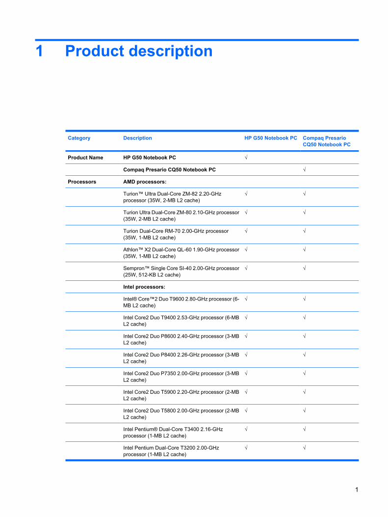
Category Description HP G50 Notebook PC Compaq PresarioCQ50 Notebook PC
Product Name HP G50 Notebook PC √
Compaq Presario CQ50 Notebook PC √
Processors AMD processors:
Turion™ Ultra Dual-Core ZM-82 2.20-GHzprocessor (35W, 2-MB L2 cache)
√ √
Turion Ultra Dual-Core ZM-80 2.10-GHz processor(35W, 2-MB L2 cache)
√ √
Turion Dual-Core RM-70 2.00-GHz processor(35W, 1-MB L2 cache)
√ √
Athlon™ X2 Dual-Core QL-60 1.90-GHz processor(35W, 1-MB L2 cache)
√ √
Sempron™ Single Core SI-40 2.00-GHz processor(25W, 512-KB L2 cache)
√ √
Intel processors:
Intel® Core™2 Duo T9600 2.80-GHz processor (6-MB L2 cache)
√ √
Intel Core2 Duo T9400 2.53-GHz processor (6-MBL2 cache)
√ √
Intel Core2 Duo P8600 2.40-GHz processor (3-MBL2 cache)
√ √
Intel Core2 Duo P8400 2.26-GHz processor (3-MBL2 cache)
√ √
Intel Core2 Duo P7350 2.00-GHz processor (3-MBL2 cache)
√ √
Intel Core2 Duo T5900 2.20-GHz processor (2-MBL2 cache)
√ √
Intel Core2 Duo T5800 2.00-GHz processor (2-MBL2 cache)
√ √
Intel Pentium® Dual-Core T3400 2.16-GHzprocessor (1-MB L2 cache)
√ √
Intel Pentium Dual-Core T3200 2.00-GHzprocessor (1-MB L2 cache)
√ √
1
Category Description HP G50 Notebook PC Compaq PresarioCQ50 Notebook PC
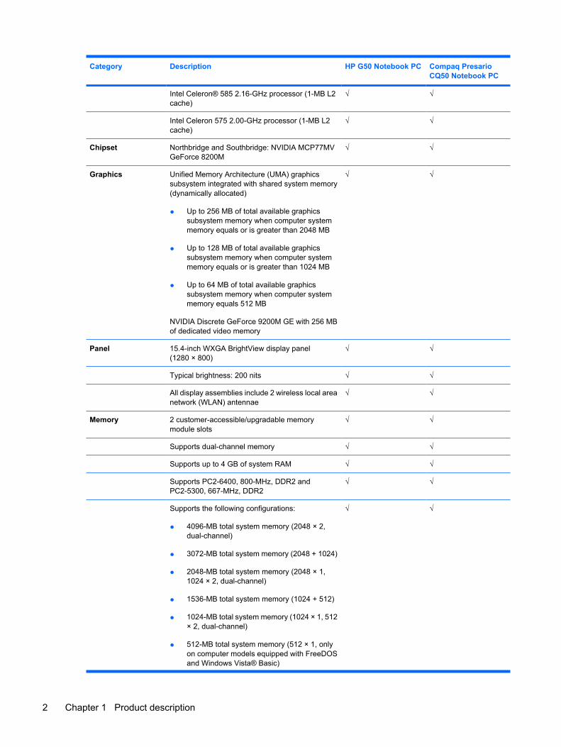
Intel Celeron® 585 2.16-GHz processor (1-MB L2cache)
√ √
Intel Celeron 575 2.00-GHz processor (1-MB L2cache)
√ √
Chipset Northbridge and Southbridge: NVIDIA MCP77MVGeForce 8200M
√ √
Graphics Unified Memory Architecture (UMA) graphicssubsystem integrated with shared system memory(dynamically allocated)
● Up to 256 MB of total available graphicssubsystem memory when computer systemmemory equals or is greater than 2048 MB
● Up to 128 MB of total available graphicssubsystem memory when computer systemmemory equals or is greater than 1024 MB
● Up to 64 MB of total available graphicssubsystem memory when computer systemmemory equals 512 MB
NVIDIA Discrete GeForce 9200M GE with 256 MBof dedicated video memory
√ √
Panel 15.4-inch WXGA BrightView display panel(1280 × 800)
√ √
Typical brightness: 200 nits √ √
All display assemblies include 2 wireless local areanetwork (WLAN) antennae
√ √
Memory 2 customer-accessible/upgradable memorymodule slots
√ √
Supports dual-channel memory √ √
Supports up to 4 GB of system RAM √ √
Supports PC2-6400, 800-MHz, DDR2 andPC2-5300, 667-MHz, DDR2
√ √
Supports the following configurations:
● 4096-MB total system memory (2048 × 2,dual-channel)
● 3072-MB total system memory (2048 + 1024)
● 2048-MB total system memory (2048 × 1,1024 × 2, dual-channel)
● 1536-MB total system memory (1024 + 512)
● 1024-MB total system memory (1024 × 1, 512× 2, dual-channel)
● 512-MB total system memory (512 × 1, onlyon computer models equipped with FreeDOSand Windows Vista® Basic)
√ √
2 Chapter 1 Product description
Category Description HP G50 Notebook PC Compaq PresarioCQ50 Notebook PC
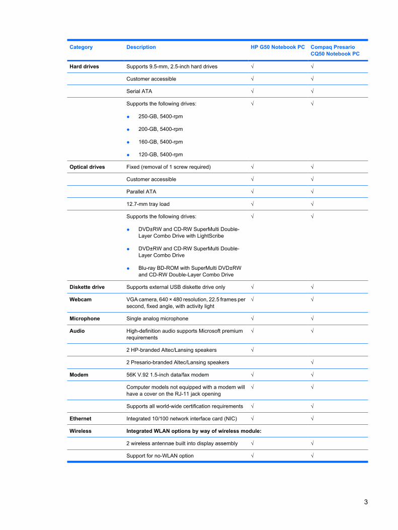
Hard drives Supports 9.5-mm, 2.5-inch hard drives √ √
Customer accessible √ √
Serial ATA √ √
Supports the following drives:
● 250-GB, 5400-rpm
● 200-GB, 5400-rpm
● 160-GB, 5400-rpm
● 120-GB, 5400-rpm
√ √
Optical drives Fixed (removal of 1 screw required) √ √
Customer accessible √ √
Parallel ATA √ √
12.7-mm tray load √ √
Supports the following drives:
● DVD±RW and CD-RW SuperMulti Double-Layer Combo Drive with LightScribe
● DVD±RW and CD-RW SuperMulti Double-Layer Combo Drive
● Blu-ray BD-ROM with SuperMulti DVD±RWand CD-RW Double-Layer Combo Drive
√ √
Diskette drive Supports external USB diskette drive only √ √
Webcam VGA camera, 640 × 480 resolution, 22.5 frames persecond, fixed angle, with activity light
√ √
Microphone Single analog microphone √ √
Audio High-definition audio supports Microsoft premiumrequirements
√ √
2 HP-branded Altec/Lansing speakers √
2 Presario-branded Altec/Lansing speakers √
Modem 56K V.92 1.5-inch data/fax modem √ √
Computer models not equipped with a modem willhave a cover on the RJ-11 jack opening
√ √
Supports all world-wide certification requirements √ √
Ethernet Integrated 10/100 network interface card (NIC) √ √
Wireless Integrated WLAN options by way of wireless module:
2 wireless antennae built into display assembly √ √
Support for no-WLAN option √ √
3
Category Description HP G50 Notebook PC Compaq PresarioCQ50 Notebook PC
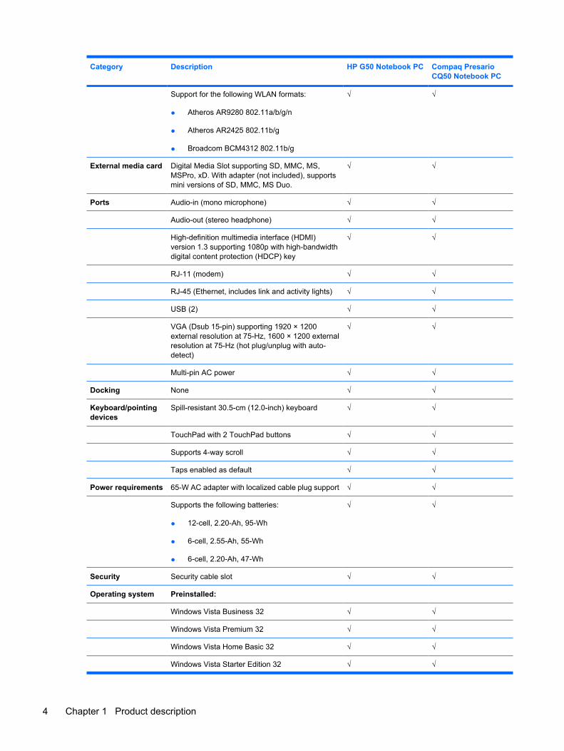
Support for the following WLAN formats:
● Atheros AR9280 802.11a/b/g/n
● Atheros AR2425 802.11b/g
● Broadcom BCM4312 802.11b/g
√ √
External media card Digital Media Slot supporting SD, MMC, MS,MSPro, xD. With adapter (not included), supportsmini versions of SD, MMC, MS Duo.
√ √
Ports Audio-in (mono microphone) √ √
Audio-out (stereo headphone) √ √
High-definition multimedia interface (HDMI)version 1.3 supporting 1080p with high-bandwidthdigital content protection (HDCP) key
√ √
RJ-11 (modem) √ √
RJ-45 (Ethernet, includes link and activity lights) √ √
USB (2) √ √
VGA (Dsub 15-pin) supporting 1920 × 1200external resolution at 75-Hz, 1600 × 1200 externalresolution at 75-Hz (hot plug/unplug with auto-detect)
√ √
Multi-pin AC power √ √
Docking None √ √
Keyboard/pointingdevices
Spill-resistant 30.5-cm (12.0-inch) keyboard √ √
TouchPad with 2 TouchPad buttons √ √
Supports 4-way scroll √ √
Taps enabled as default √ √
Power requirements 65-W AC adapter with localized cable plug support √ √
Supports the following batteries:
● 12-cell, 2.20-Ah, 95-Wh
● 6-cell, 2.55-Ah, 55-Wh
● 6-cell, 2.20-Ah, 47-Wh
√ √
Security Security cable slot √ √
Operating system Preinstalled:
Windows Vista Business 32 √ √
Windows Vista Premium 32 √ √
Windows Vista Home Basic 32 √ √
Windows Vista Starter Edition 32 √ √
4 Chapter 1 Product description
Category Description HP G50 Notebook PC Compaq PresarioCQ50 Notebook PC
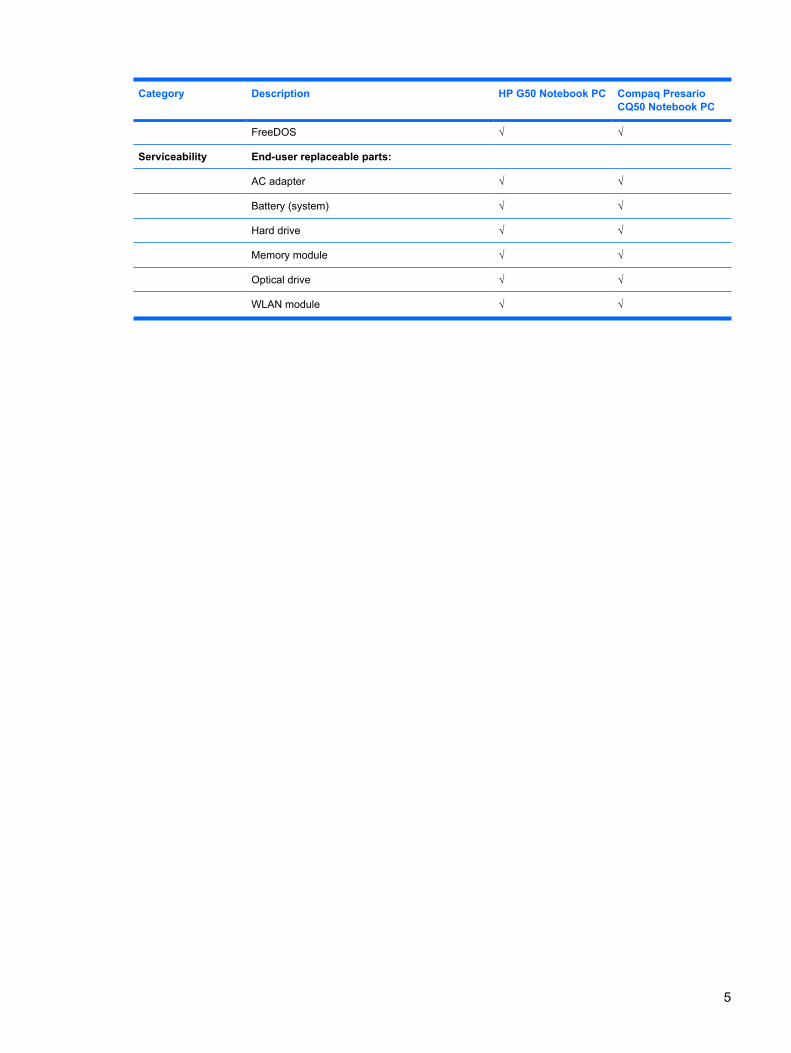
FreeDOS √ √
Serviceability End-user replaceable parts:
AC adapter √ √
Battery (system) √ √
Hard drive √ √
Memory module √ √
Optical drive √ √
WLAN module √ √
5
2 External component identification
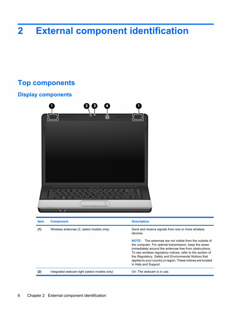
Top componentsDisplay components
Item Component Description
(1) Wireless antennae (2, select models only) Send and receive signals from one or more wirelessdevices.
NOTE: The antennae are not visible from the outside ofthe computer. For optimal transmission, keep the areasimmediately around the antennae free from obstructions.To see wireless regulatory notices, refer to the section ofthe Regulatory, Safety and Environmental Notices thatapplies to your country or region. These notices are locatedin Help and Support.
(2) Integrated webcam light (select models only) On: The webcam is in use.
6 Chapter 2 External component identification
Item Component Description
(3) Integrated webcam (select models only) Records audio and video and captures still photographs.
(4) Internal microphone Records sound.
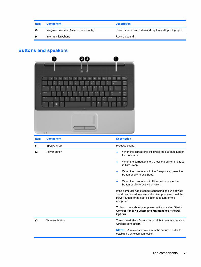
Buttons and speakers
Item Component Description
(1) Speakers (2) Produce sound.
(2) Power button ● When the computer is off, press the button to turn onthe computer.
● When the computer is on, press the button briefly toinitiate Sleep.
● When the computer is in the Sleep state, press thebutton briefly to exit Sleep.
● When the computer is in Hibernation, press thebutton briefly to exit Hibernation.
If the computer has stopped responding and Windows®shutdown procedures are ineffective, press and hold thepower button for at least 5 seconds to turn off thecomputer.
To learn more about your power settings, select Start >Control Panel > System and Maintenance > PowerOptions.
(3) Wireless button Turns the wireless feature on or off, but does not create awireless connection.
NOTE: A wireless network must be set up in order toestablish a wireless connection.
Top components 7
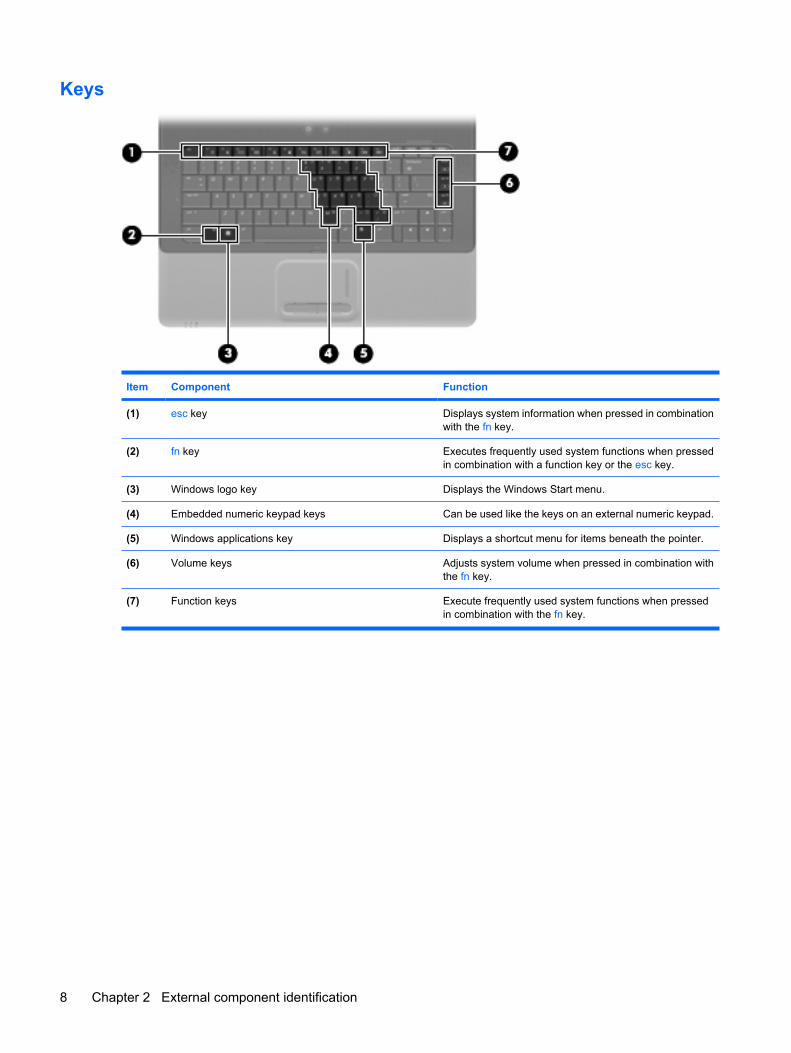
Keys
Item Component Function
(1) esc key Displays system information when pressed in combinationwith the fn key.
(2) fn key Executes frequently used system functions when pressedin combination with a function key or the esc key.
(3) Windows logo key Displays the Windows Start menu.
(4) Embedded numeric keypad keys Can be used like the keys on an external numeric keypad.
(5) Windows applications key Displays a shortcut menu for items beneath the pointer.
(6) Volume keys Adjusts system volume when pressed in combination withthe fn key.
(7) Function keys Execute frequently used system functions when pressedin combination with the fn key.
8 Chapter 2 External component identification
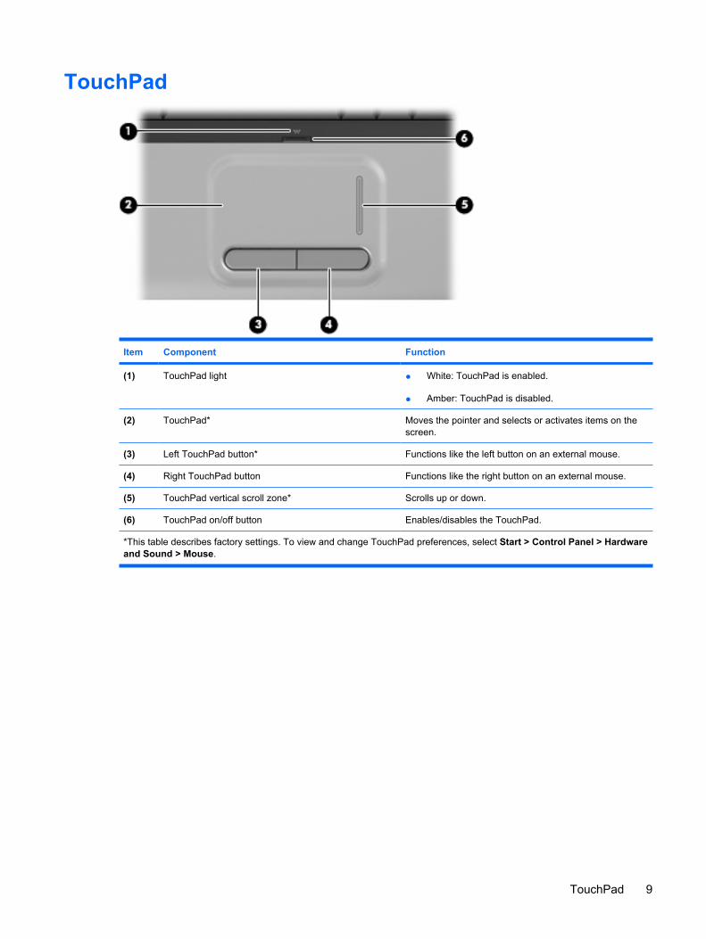
TouchPad
Item Component Function
(1) TouchPad light ● White: TouchPad is enabled.
● Amber: TouchPad is disabled.
(2) TouchPad* Moves the pointer and selects or activates items on thescreen.
(3) Left TouchPad button* Functions like the left button on an external mouse.
(4) Right TouchPad button Functions like the right button on an external mouse.
(5) TouchPad vertical scroll zone* Scrolls up or down.
(6) TouchPad on/off button Enables/disables the TouchPad.
*This table describes factory settings. To view and change TouchPad preferences, select Start > Control Panel > Hardwareand Sound > Mouse.
TouchPad 9
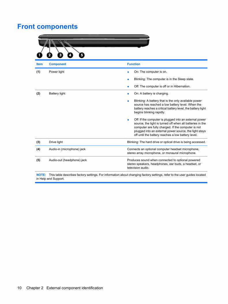
Front components
Item Component Function
(1) Power light ● On: The computer is on.
● Blinking: The computer is in the Sleep state.
● Off: The computer is off or in Hibernation.
(2) Battery light ● On: A battery is charging.
● Blinking: A battery that is the only available powersource has reached a low battery level. When thebattery reaches a critical battery level, the battery lightbegins blinking rapidly.
● Off: If the computer is plugged into an external powersource, the light is turned off when all batteries in thecomputer are fully charged. If the computer is notplugged into an external power source, the light staysoff until the battery reaches a low battery level.
(3) Drive light Blinking: The hard drive or optical drive is being accessed.
(4) Audio-in (microphone) jack Connects an optional computer headset microphone,stereo array microphone, or monaural microphone.
(5) Audio-out (headphone) jack Produces sound when connected to optional poweredstereo speakers, headphones, ear buds, a headset, ortelevision audio.
NOTE: This table describes factory settings. For information about changing factory settings, refer to the user guides locatedin Help and Support.
10 Chapter 2 External component identification
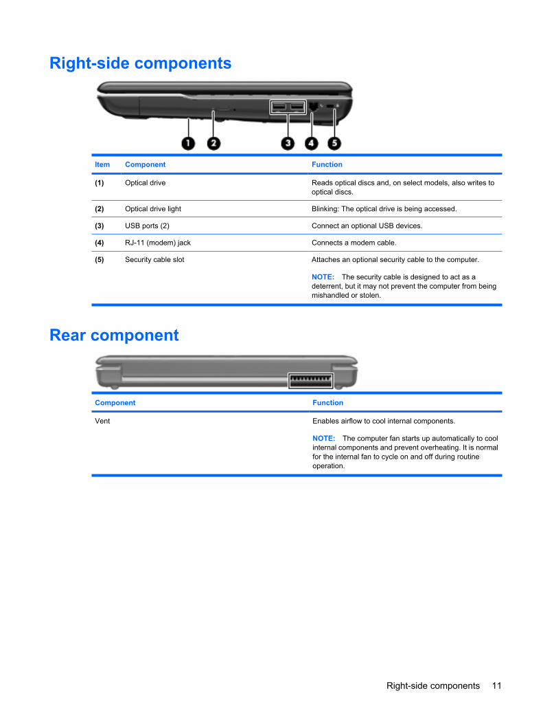
Right-side components
Item Component Function
(1) Optical drive Reads optical discs and, on select models, also writes tooptical discs.
(2) Optical drive light Blinking: The optical drive is being accessed.
(3) USB ports (2) Connect an optional USB devices.
(4) RJ-11 (modem) jack Connects a modem cable.
(5) Security cable slot Attaches an optional security cable to the computer.
NOTE: The security cable is designed to act as adeterrent, but it may not prevent the computer from beingmishandled or stolen.
Rear component
Component Function
Vent Enables airflow to cool internal components.
NOTE: The computer fan starts up automatically to coolinternal components and prevent overheating. It is normalfor the internal fan to cycle on and off during routineoperation.
Right-side components 11
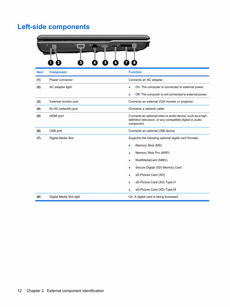
Left-side components
Item Component Function
(1) Power connector Connects an AC adapter.
(2) AC adapter light ● On: The computer is connected to external power.
● Off: The computer is not connected to external power.
(3) External monitor port Connects an external VGA monitor or projector.
(4) RJ-45 (network) jack Connects a network cable.
(5) HDMI port Connects an optional video or audio device, such as a high-definition television, or any compatible digital or audiocomponent.
(6) USB port Connects an optional USB device.
(7) Digital Media Slot Supports the following optional digital card formats:
● Memory Stick (MS)
● Memory Stick Pro (MSP)
● MultiMediaCard (MMC)
● Secure Digital (SD) Memory Card
● xD-Picture Card (XD)
● xD-Picture Card (XD) Type H
● xD-Picture Card (XD) Type M
(8) Digital Media Slot light On: A digital card is being accessed.
12 Chapter 2 External component identification
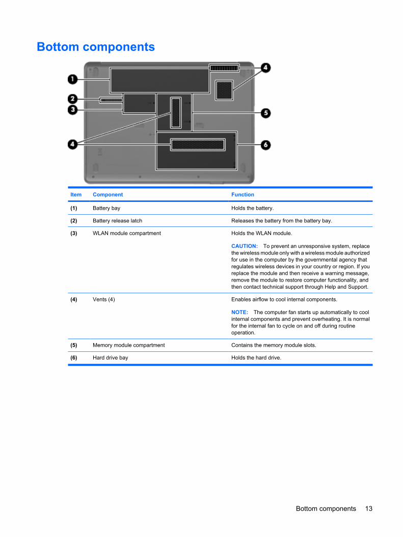
Bottom components
Item Component Function
(1) Battery bay Holds the battery.
(2) Battery release latch Releases the battery from the battery bay.
(3) WLAN module compartment Holds the WLAN module.
CAUTION: To prevent an unresponsive system, replacethe wireless module only with a wireless module authorizedfor use in the computer by the governmental agency thatregulates wireless devices in your country or region. If youreplace the module and then receive a warning message,remove the module to restore computer functionality, andthen contact technical support through Help and Support.
(4) Vents (4) Enables airflow to cool internal components.
NOTE: The computer fan starts up automatically to coolinternal components and prevent overheating. It is normalfor the internal fan to cycle on and off during routineoperation.
(5) Memory module compartment Contains the memory module slots.
(6) Hard drive bay Holds the hard drive.
Bottom components 13
3 Illustrated parts catalog
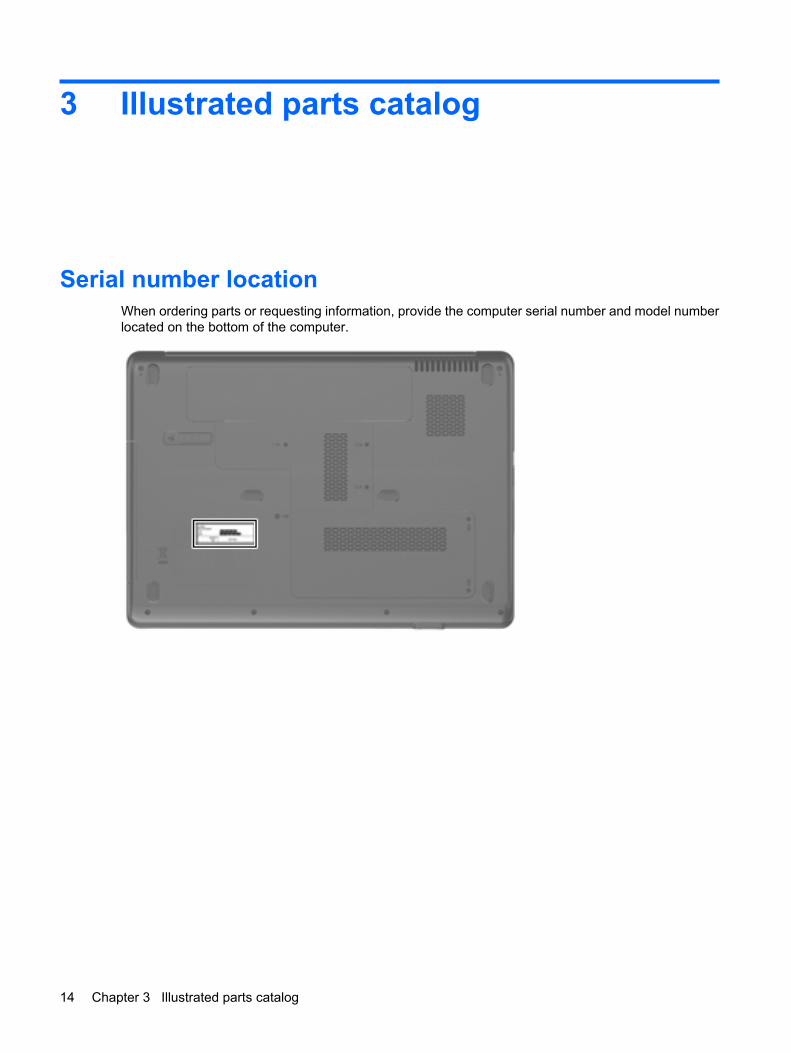
Serial number locationWhen ordering parts or requesting information, provide the computer serial number and model numberlocated on the bottom of the computer.
14 Chapter 3 Illustrated parts catalog
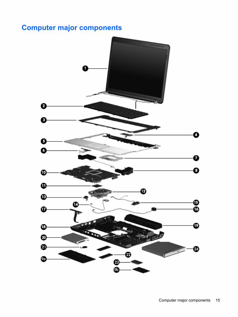
Computer major components
Computer major components 15
Item Description Spare part number
(1) 15.4-inch, WXGA+BrightView display assemblies (include 2 WLAN antenna transceivers and cables, microphonesand cables, and logo)
For use only with HP G50 computer models
Includes webcam module and cable 487603-001
Does not include webcam module and cable 487602-001
For use only with Compaq CQ50 computer models
Includes webcam module and cable 485047-001
Does not include webcam module and cable 485046-001
Refer to Display assembly components on page 22, for more display assembly component spare part information.
(2) Keyboards (include keyboard cable)
For use in Belgium 486654-A41
For use in Canada 486654-121
For use in the Czech Republic 486654-221
For use in France 486654-051
For use in Denmark, Finland, and Norway 486654-DH1
For use in Germany 486654-041
For use in Greece 486654-151
For use in Israel 486654-BB1
For use in Italy 486654-061
For use in Latin America 486654-161
For use in the Netherlands 486654-B31
For use in Portugal 486654-131
For use in Russia 486654-251
For use in Saudi Arabia 486654-171
For use in South Korea 486654-AD1
For use in Spain 486654-071
For use in Switzerland 486654-111
For use in Taiwan 486654-AB1
For use in Thailand 486654-281
For use in Turkey 486654-141
For use in the United Kingdom 486654-031
For use in the United States 486654-001
(3) Keyboard cover 486626-001
(4) Power button board (includes power button board cable) 486627-001
16 Chapter 3 Illustrated parts catalog
Item Description Spare part number
(5) Top cover (includes TouchPad board) 486628-001
(6) TouchPad on/off button board (includes cables) 486630-001
(7) TouchPad button board and bracket 486629-001
(8) Speakers (includes left and right speakers and cables) 486632-001
Plastics Kit (see Plastics Kit on page 23 for more Plastics Kit spare part information) 486621-001
(9a) Hard drive cover
(9b) WLAN module compartment cover
(10) System boards (include UMA graphics subsystem memory, built-in modem, and replacement thermal material)
Equipped with AMD processors:
For use only with HP G50 and Compaq CQ50 computer models equipped with a DigitalMedia Slot and an HDMI port
489810-001
For use only with HP G50 and Compaq CQ50 computer models equipped only with a DigitalMedia Slot
486550-001
For use only with Compaq CQ50 computer models equipped with an HDMI port 490828-001
For use only with Compaq CQ50 computer models not equipped with an HDMI port 494182-001
Equipped with Intel processors:
For use only with HP G50 and Compaq CQ50 computer models equipped with a GM45chipset, Digital Media Slot, and HDMI port
485218-001
For use only with HP G50 and Compaq CQ50 computer models equipped with a GM45chipset and Digital Media Slot
494281-001
For use only with HP G50 and Compaq CQ50 computer models equipped with a GL40chipset, Digital Media Slot, and HDMI port
485219-001
For use only with HP G50 and Compaq CQ50 computer models equipped with a GL40chipset and Digital Media Slot
494282-001
For use only with HP G50 and Compaq CQ50 computer models equipped with NVIDIAGeForce 9200M graphics, a Digital Media Slot, and an HDMI port
488338-001
For use only with HP G50 and Compaq CQ50 computer models equipped with NVIDIAGeForce 9200M graphics and a Digital Media Slot
494283-001
(11) Processors (include replacement thermal material)
● AMD Turion Ultra Dual-Core ZM-82 2.20-GHz processor (35W, 2-MB L2 cache) 480852-006
● AMD Turion Ultra Dual-Core ZM-80 2.10-GHz processor (35W, 2-MB L2 cache) 480851-006
● AMD Turion Dual-Core RM-70 2.00-GHz processor (35W, 1-MB L2 cache) 480857-005
● AMD Sempron Single Core SI-40 2.00-GHz processor (25W, 512-KB L2 cache) 487350-003
● AMD Athlon X2 Dual-Core QL-60 1.90-GHz processor (35W, 1-MB L2 cache) 480856-005
● Intel Core2 Duo T9600 2.80-GHz processor (6-MB L2 cache) 489157-006
● Intel Core2 Duo T9400 2.53-GHz processor (6-MB L2 cache) 483260-006
● Intel Core2 Duo P8600 2.40-GHz processor (3-MB L2 cache) 483259-005
● Intel Core2 Duo P8400 2.26-GHz processor (3-MB L2 cache) 483258-006
Computer major components 17
Item Description Spare part number
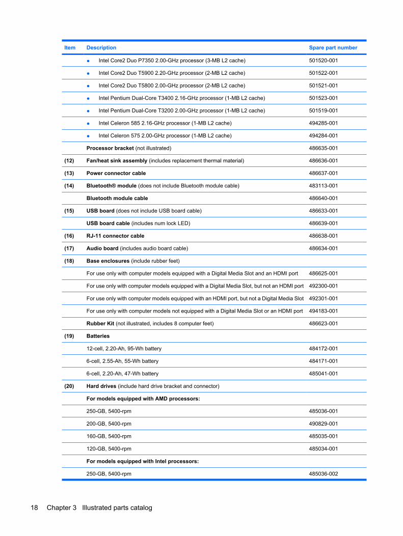
● Intel Core2 Duo P7350 2.00-GHz processor (3-MB L2 cache) 501520-001
● Intel Core2 Duo T5900 2.20-GHz processor (2-MB L2 cache) 501522-001
● Intel Core2 Duo T5800 2.00-GHz processor (2-MB L2 cache) 501521-001
● Intel Pentium Dual-Core T3400 2.16-GHz processor (1-MB L2 cache) 501523-001
● Intel Pentium Dual-Core T3200 2.00-GHz processor (1-MB L2 cache) 501519-001
● Intel Celeron 585 2.16-GHz processor (1-MB L2 cache) 494285-001
● Intel Celeron 575 2.00-GHz processor (1-MB L2 cache) 494284-001
Processor bracket (not illustrated) 486635-001
(12) Fan/heat sink assembly (includes replacement thermal material) 486636-001
(13) Power connector cable 486637-001
(14) Bluetooth® module (does not include Bluetooth module cable) 483113-001
Bluetooth module cable 486640-001
(15) USB board (does not include USB board cable) 486633-001
USB board cable (includes num lock LED) 486639-001
(16) RJ-11 connector cable 486638-001
(17) Audio board (includes audio board cable) 486634-001
(18) Base enclosures (include rubber feet)
For use only with computer models equipped with a Digital Media Slot and an HDMI port 486625-001
For use only with computer models equipped with a Digital Media Slot, but not an HDMI port 492300-001
For use only with computer models equipped with an HDMI port, but not a Digital Media Slot 492301-001
For use only with computer models not equipped with a Digital Media Slot or an HDMI port 494183-001
Rubber Kit (not illustrated, includes 8 computer feet) 486623-001
(19) Batteries
12-cell, 2.20-Ah, 95-Wh battery 484172-001
6-cell, 2.55-Ah, 55-Wh battery 484171-001
6-cell, 2.20-Ah, 47-Wh battery 485041-001
(20) Hard drives (include hard drive bracket and connector)
For models equipped with AMD processors:
250-GB, 5400-rpm 485036-001
200-GB, 5400-rpm 490829-001
160-GB, 5400-rpm 485035-001
120-GB, 5400-rpm 485034-001
For models equipped with Intel processors:
250-GB, 5400-rpm 485036-002
18 Chapter 3 Illustrated parts catalog
Item Description Spare part number
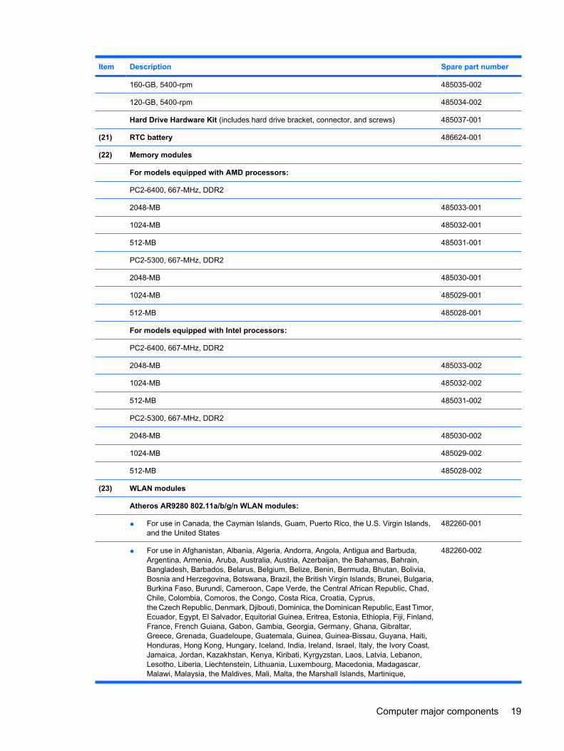
160-GB, 5400-rpm 485035-002
120-GB, 5400-rpm 485034-002
Hard Drive Hardware Kit (includes hard drive bracket, connector, and screws) 485037-001
(21) RTC battery 486624-001
(22) Memory modules
For models equipped with AMD processors:
PC2-6400, 667-MHz, DDR2
2048-MB 485033-001
1024-MB 485032-001
512-MB 485031-001
PC2-5300, 667-MHz, DDR2
2048-MB 485030-001
1024-MB 485029-001
512-MB 485028-001
For models equipped with Intel processors:
PC2-6400, 667-MHz, DDR2
2048-MB 485033-002
1024-MB 485032-002
512-MB 485031-002
PC2-5300, 667-MHz, DDR2
2048-MB 485030-002
1024-MB 485029-002
512-MB 485028-002
(23) WLAN modules
Atheros AR9280 802.11a/b/g/n WLAN modules:
● For use in Canada, the Cayman Islands, Guam, Puerto Rico, the U.S. Virgin Islands,and the United States
482260-001
● For use in Afghanistan, Albania, Algeria, Andorra, Angola, Antigua and Barbuda,Argentina, Armenia, Aruba, Australia, Austria, Azerbaijan, the Bahamas, Bahrain,Bangladesh, Barbados, Belarus, Belgium, Belize, Benin, Bermuda, Bhutan, Bolivia,Bosnia and Herzegovina, Botswana, Brazil, the British Virgin Islands, Brunei, Bulgaria,Burkina Faso, Burundi, Cameroon, Cape Verde, the Central African Republic, Chad,Chile, Colombia, Comoros, the Congo, Costa Rica, Croatia, Cyprus,the Czech Republic, Denmark, Djibouti, Dominica, the Dominican Republic, East Timor,Ecuador, Egypt, El Salvador, Equitorial Guinea, Eritrea, Estonia, Ethiopia, Fiji, Finland,France, French Guiana, Gabon, Gambia, Georgia, Germany, Ghana, Gibraltar,Greece, Grenada, Guadeloupe, Guatemala, Guinea, Guinea-Bissau, Guyana, Haiti,Honduras, Hong Kong, Hungary, Iceland, India, Ireland, Israel, Italy, the Ivory Coast,Jamaica, Jordan, Kazakhstan, Kenya, Kiribati, Kyrgyzstan, Laos, Latvia, Lebanon,Lesotho, Liberia, Liechtenstein, Lithuania, Luxembourg, Macedonia, Madagascar,Malawi, Malaysia, the Maldives, Mali, Malta, the Marshall Islands, Martinique,
482260-002
Computer major components 19
Item Description Spare part number
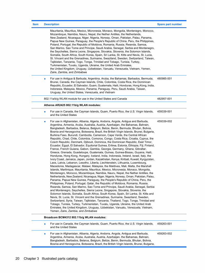
Mauritania, Mauritius, Mexico, Micronesia, Monaco, Mongolia, Montenegro, Morocco,Mozambique, Namibia, Nauru, Nepal, the Nether Antilles, the Netherlands,New Zealand, Nicaragua, Niger, Nigeria, Norway, Oman, Pakistan, Palau, Panama,Papua New Guinea, Paraguay, the People's Republic of China, Peru, the Philippines,Poland, Portugal, the Republic of Moldova, Romania, Russia, Rwanda, Samoa,San Marino, Sao Tome and Principe, Saudi Arabia, Senegal, Serbia and Montenegro,the Seychelles, Sierra Leone, Singapore, Slovakia, Slovenia, the Solomon Islands,Somalia, South Africa, South Korea, Spain, Sri Lanka, St. Kitts and Nevis, St. Lucia,St. Vincent and the Grenadines, Suriname, Swaziland, Sweden, Switzerland, Taiwan,Tajikistan, Tanzania, Togo, Tonga, Trinidad and Tobago, Tunisia, Turkey,Turkmenistan, Tuvalu, Uganda, Ukraine, the United Arab Emirates,the United Kingdom, Uruguay, Uzbekistan, Vanuatu, Venezuela, Vietnam, Yemen,Zaire, Zambia, and Zimbabwe
● For use in Antigua & Barbuda, Argentina, Aruba, the Bahamas, Barbados, Bermuda,Brunei, Canada, the Cayman Islands, Chile, Colombia, Costa Rica, the DominicanRepublic, Ecuador, El Salvador, Guam, Guatemala, Haiti, Honduras, Hong Kong, India,Indonesia, Malaysia, Mexico, Panama, Paraguay, Peru, Saudi Arabia, Taiwan,Uruguay, the United States, Venezuela, and Vietnam
480985-001
802.11a/b/g WLAN module for use in the United States and Canada 482957-001
Atheros AR2425 802.11b/g WLAN modules:
● For use in Canada, the Cayman Islands, Guam, Puerto Rico, the U.S. Virgin Islands,and the United States
459339-001
● For use in Afghanistan, Albania, Algeria, Andorra, Angola, Antigua and Barbuda,Argentina, Armenia, Aruba, Australia, Austria, Azerbaijan, the Bahamas, Bahrain,Bangladesh, Barbados, Belarus, Belgium, Belize, Benin, Bermuda, Bhutan, Bolivia,Bosnia and Herzegovina, Botswana, Brazil, the British Virgin Islands, Brunei, Bulgaria,Burkina Faso, Burundi, Cambodia, Cameroon, Cape Verde, the Central AfricanRepublic, Chad, Chile, Colombia, Comoros, Congo, Costa Rica, Croatia, Cyprus, theCzech Republic, Denmark, Djibouti, Dominica, the Dominican Republic, East Timor,Ecuador, Egypt, El Salvador, Equitorial Guinea, Eritrea, Estonia, Ethiopia, Fiji, Finland,France, French Guiana, Gabon, Gambia, Georgia, Germany, Ghana, Gibraltar,Greece, Grenada, Guadeloupe, Guatemala, Guinea, Guinea-Bissau, Guyana, Haiti,Honduras, Hong Kong, Hungary, Iceland, India, Indonesia, Ireland, Israel, Italy, theIvory Coast, Jamaica, Japan, Jordan, Kazakhstan, Kenya, Kiribati, Kuwait, Kyrgyzstan,Laos, Latvia, Lebanon, Lesotho, Liberia, Liechtenstein, Lithuania, Luxembourg,Macedonia, Madagascar, Malawi, Malaysia, the Maldives, Mali, Malta, the MarshallIslands, Martinique, Mauritania, Mauritius, Mexico, Micronesia, Monaco, Mongolia,Montenegro, Morocco, Mozambique, Namibia, Nauru, Nepal, the Nether Antilles, theNetherlands, New Zealand, Nicaragua, Niger, Nigeria, Norway, Oman, Pakistan, Palau,Panama, Papua New Guinea, Paraguay, the People's Republic of China, Peru, thePhilippines, Poland, Portugal, Qatar, the Republic of Moldova, Romania, Russia,Rwanda, Samoa, San Marino, Sao Tome and Principe, Saudi Arabia, Senegal, Serbiaand Montenegro, Seychelles, Sierra Leone, Singapore, Slovakia, Slovenia, theSolomon Islands, Somalia, South Africa, South Korea, Spain, Sri Lanka, St. Kitts andNevis, St. Lucia, St. Vincent and the Grenadines, Suriname, Swaziland, Sweden,Switzerland, Syria, Taiwan, Tajikistan, Tanzania, Thailand, Togo, Tonga, Trinidad andTobago, Tunisia, Turkey, Turkmenistan, Tuvalu, Uganda, Ukraine, the United ArabEmirates, the United Kingdom, Uruguay, Uzbekistan, Vanuatu, Venezuela, Vietnam,Yemen, Zaire, Zambia, and Zimbabwe
459339-002
Broadcom BCM4312 802.11b/g WLAN modules:
● For use in Canada, the Cayman Islands, Guam, Puerto Rico, the U.S. Virgin Islands,and the United States
459263-001
● For use in Afghanistan, Albania, Algeria, Andorra, Angola, Antigua and Barbuda,Argentina, Armenia, Aruba, Australia, Austria, Azerbaijan, the Bahamas, Bahrain,Bangladesh, Barbados, Belarus, Belgium, Belize, Benin, Bermuda, Bhutan, Bolivia,Bosnia and Herzegovina, Botswana, Brazil, the British Virgin Islands, Brunei, Bulgaria,
459263-002
20 Chapter 3 Illustrated parts catalog
Item Description Spare part number
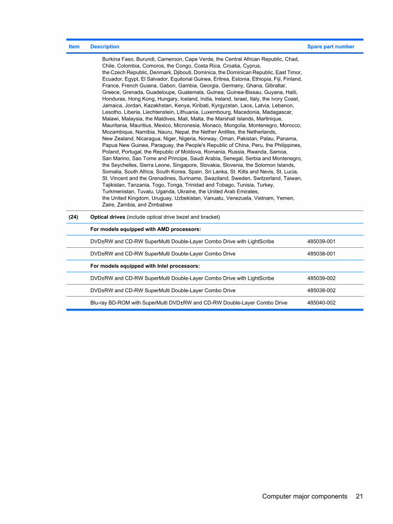
Burkina Faso, Burundi, Cameroon, Cape Verde, the Central African Republic, Chad,Chile, Colombia, Comoros, the Congo, Costa Rica, Croatia, Cyprus,the Czech Republic, Denmark, Djibouti, Dominica, the Dominican Republic, East Timor,Ecuador, Egypt, El Salvador, Equitorial Guinea, Eritrea, Estonia, Ethiopia, Fiji, Finland,France, French Guiana, Gabon, Gambia, Georgia, Germany, Ghana, Gibraltar,Greece, Grenada, Guadeloupe, Guatemala, Guinea, Guinea-Bissau, Guyana, Haiti,Honduras, Hong Kong, Hungary, Iceland, India, Ireland, Israel, Italy, the Ivory Coast,Jamaica, Jordan, Kazakhstan, Kenya, Kiribati, Kyrgyzstan, Laos, Latvia, Lebanon,Lesotho, Liberia, Liechtenstein, Lithuania, Luxembourg, Macedonia, Madagascar,Malawi, Malaysia, the Maldives, Mali, Malta, the Marshall Islands, Martinique,Mauritania, Mauritius, Mexico, Micronesia, Monaco, Mongolia, Montenegro, Morocco,Mozambique, Namibia, Nauru, Nepal, the Nether Antilles, the Netherlands,New Zealand, Nicaragua, Niger, Nigeria, Norway, Oman, Pakistan, Palau, Panama,Papua New Guinea, Paraguay, the People's Republic of China, Peru, the Philippines,Poland, Portugal, the Republic of Moldova, Romania, Russia, Rwanda, Samoa,San Marino, Sao Tome and Principe, Saudi Arabia, Senegal, Serbia and Montenegro,the Seychelles, Sierra Leone, Singapore, Slovakia, Slovenia, the Solomon Islands,Somalia, South Africa, South Korea, Spain, Sri Lanka, St. Kitts and Nevis, St. Lucia,St. Vincent and the Grenadines, Suriname, Swaziland, Sweden, Switzerland, Taiwan,Tajikistan, Tanzania, Togo, Tonga, Trinidad and Tobago, Tunisia, Turkey,Turkmenistan, Tuvalu, Uganda, Ukraine, the United Arab Emirates,the United Kingdom, Uruguay, Uzbekistan, Vanuatu, Venezuela, Vietnam, Yemen,Zaire, Zambia, and Zimbabwe
(24) Optical drives (include optical drive bezel and bracket)
For models equipped with AMD processors:
DVD±RW and CD-RW SuperMulti Double-Layer Combo Drive with LightScribe 485039-001
DVD±RW and CD-RW SuperMulti Double-Layer Combo Drive 485038-001
For models equipped with Intel processors:
DVD±RW and CD-RW SuperMulti Double-Layer Combo Drive with LightScribe 485039-002
DVD±RW and CD-RW SuperMulti Double-Layer Combo Drive 485038-002
Blu-ray BD-ROM with SuperMulti DVD±RW and CD-RW Double-Layer Combo Drive 485040-002
Computer major components 21
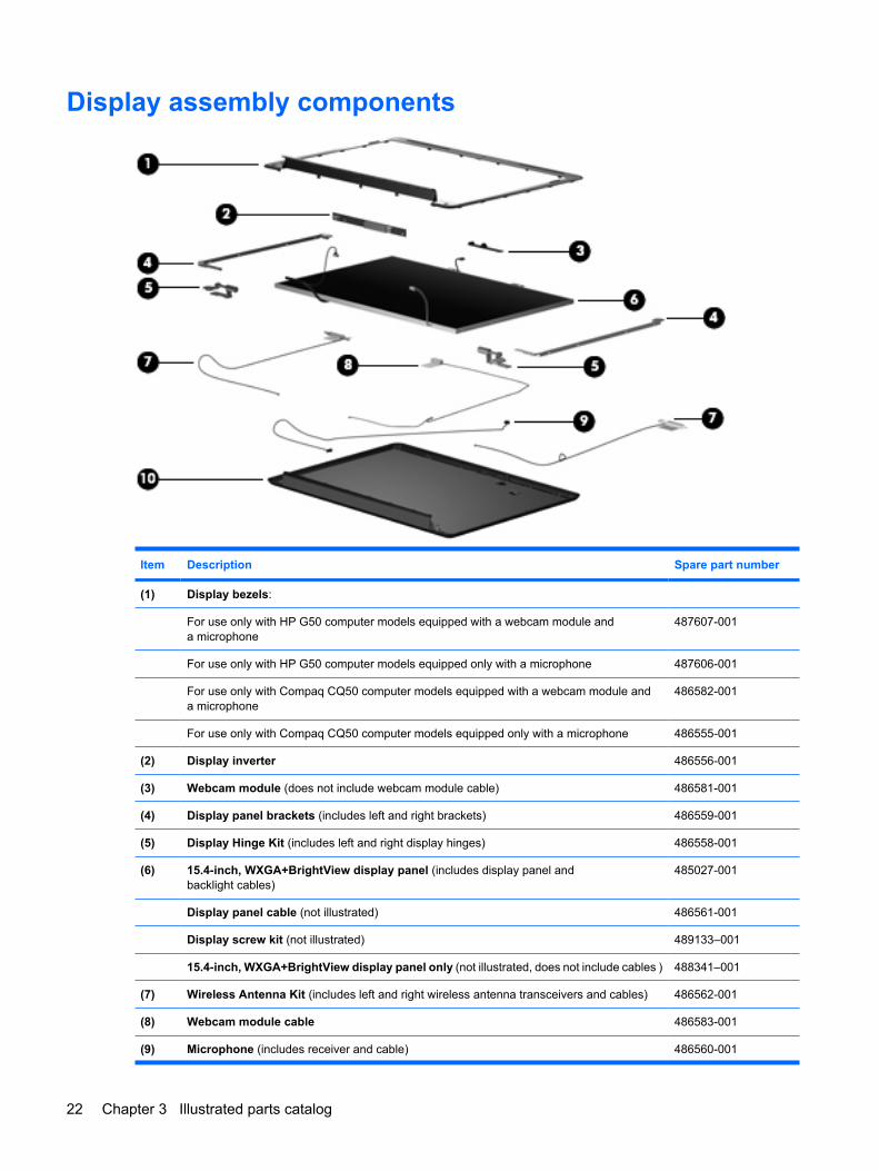
Display assembly components
Item Description Spare part number
(1) Display bezels:
For use only with HP G50 computer models equipped with a webcam module anda microphone
487607-001
For use only with HP G50 computer models equipped only with a microphone 487606-001
For use only with Compaq CQ50 computer models equipped with a webcam module anda microphone
486582-001
For use only with Compaq CQ50 computer models equipped only with a microphone 486555-001
(2) Display inverter 486556-001
(3) Webcam module (does not include webcam module cable) 486581-001
(4) Display panel brackets (includes left and right brackets) 486559-001
(5) Display Hinge Kit (includes left and right display hinges) 486558-001
(6) 15.4-inch, WXGA+BrightView display panel (includes display panel andbacklight cables)
485027-001
Display panel cable (not illustrated) 486561-001
Display screw kit (not illustrated) 489133–001
15.4-inch, WXGA+BrightView display panel only (not illustrated, does not include cables ) 488341–001
(7) Wireless Antenna Kit (includes left and right wireless antenna transceivers and cables) 486562-001
(8) Webcam module cable 486583-001
(9) Microphone (includes receiver and cable) 486560-001
22 Chapter 3 Illustrated parts catalog
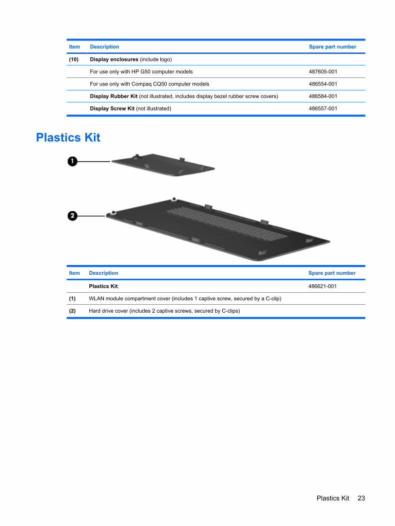
Item Description Spare part number
(10) Display enclosures (include logo)
For use only with HP G50 computer models 487605-001
For use only with Compaq CQ50 computer models 486554-001
Display Rubber Kit (not illustrated, includes display bezel rubber screw covers) 486584-001
Display Screw Kit (not illustrated) 486557-001
Plastics Kit
Item Description Spare part number
Plastics Kit: 486621-001
(1) WLAN module compartment cover (includes 1 captive screw, secured by a C-clip)
(2) Hard drive cover (includes 2 captive screws, secured by C-clips)
Plastics Kit 23
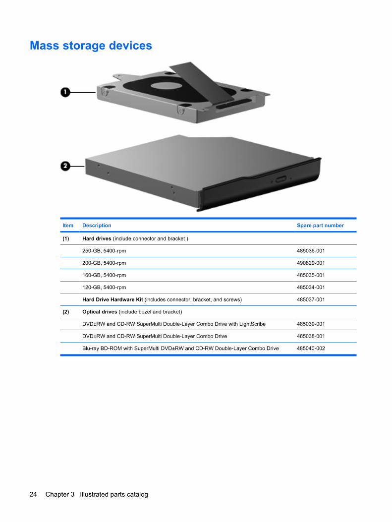
Mass storage devices
Item Description Spare part number
(1) Hard drives (include connector and bracket )
250-GB, 5400-rpm 485036-001
200-GB, 5400-rpm 490829-001
160-GB, 5400-rpm 485035-001
120-GB, 5400-rpm 485034-001
Hard Drive Hardware Kit (includes connector, bracket, and screws) 485037-001
(2) Optical drives (include bezel and bracket)
DVD±RW and CD-RW SuperMulti Double-Layer Combo Drive with LightScribe 485039-001
DVD±RW and CD-RW SuperMulti Double-Layer Combo Drive 485038-001
Blu-ray BD-ROM with SuperMulti DVD±RW and CD-RW Double-Layer Combo Drive 485040-002
24 Chapter 3 Illustrated parts catalog
Miscellaneous partsDescription Spare part number
65-W PFC AC adapter 463958-001
Power cords:
For use in Argentina 490371-D01
For use in Australia 490371-011
For use in Denmark 490371-081
For use in Europe 490371-021
For use in India 490371-D61
For use in Israel 490371-BB1
For use in Italy 490371-061
For use in South Africa 490371-AR1
For use in South Korea 490371-AD1
For use in Switzerland 490371-111
For use in Taiwan 490371-AB1
For use in the United Kingdom and Singapore 490371-031
For use in the United States 490371-001
Screw Kit
● Phillips PM3.0×3.0 screw
● Phillips PM2.5×10.0 captive screw
● Phillips PM2.5×10.0 screw
● Phillips PM2.5×8.0 screw
● Phillips PM2.5×7.0 screw
● Phillips PM2.5×6.0 captive screw
● Phillips PM2.5×5.0 screw
● Phillips PM2.0×10.0 captive screw
● Phillips PM2.0×6.0 screw
● Phillips PM2.0×3.0 screw
486622-001
Miscellaneous parts 25
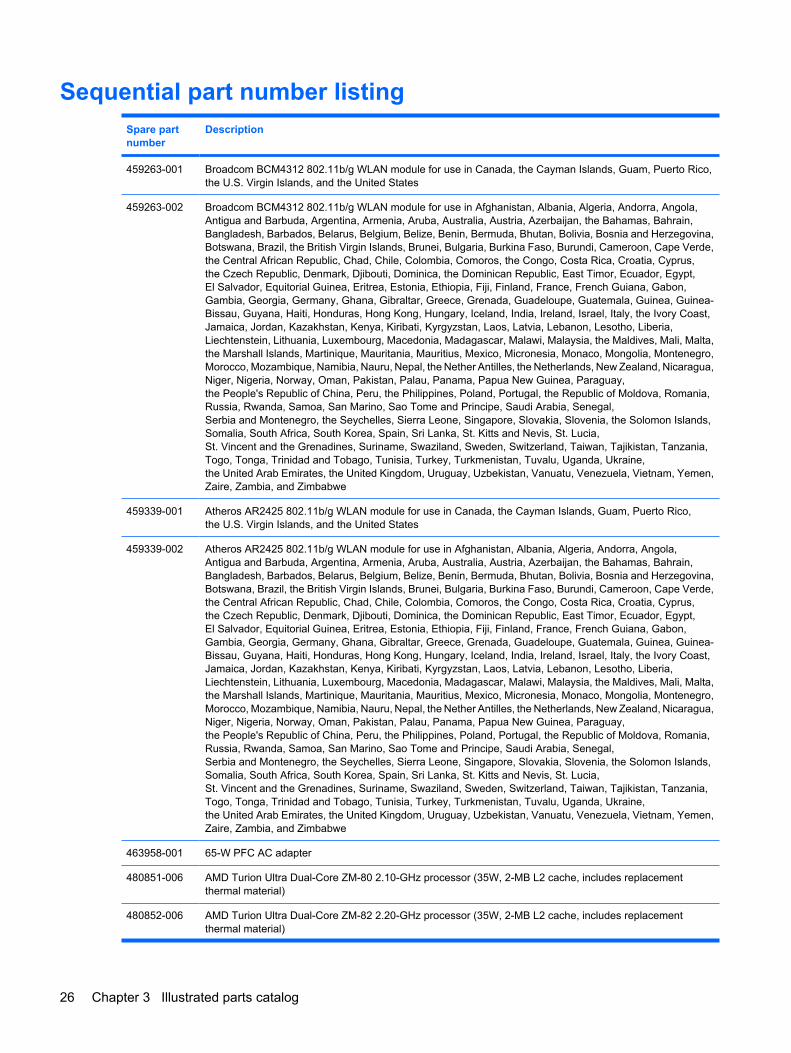
Sequential part number listingSpare partnumber
Description
459263-001 Broadcom BCM4312 802.11b/g WLAN module for use in Canada, the Cayman Islands, Guam, Puerto Rico,the U.S. Virgin Islands, and the United States
459263-002 Broadcom BCM4312 802.11b/g WLAN module for use in Afghanistan, Albania, Algeria, Andorra, Angola,Antigua and Barbuda, Argentina, Armenia, Aruba, Australia, Austria, Azerbaijan, the Bahamas, Bahrain,Bangladesh, Barbados, Belarus, Belgium, Belize, Benin, Bermuda, Bhutan, Bolivia, Bosnia and Herzegovina,Botswana, Brazil, the British Virgin Islands, Brunei, Bulgaria, Burkina Faso, Burundi, Cameroon, Cape Verde,the Central African Republic, Chad, Chile, Colombia, Comoros, the Congo, Costa Rica, Croatia, Cyprus,the Czech Republic, Denmark, Djibouti, Dominica, the Dominican Republic, East Timor, Ecuador, Egypt,El Salvador, Equitorial Guinea, Eritrea, Estonia, Ethiopia, Fiji, Finland, France, French Guiana, Gabon,Gambia, Georgia, Germany, Ghana, Gibraltar, Greece, Grenada, Guadeloupe, Guatemala, Guinea, Guinea-Bissau, Guyana, Haiti, Honduras, Hong Kong, Hungary, Iceland, India, Ireland, Israel, Italy, the Ivory Coast,Jamaica, Jordan, Kazakhstan, Kenya, Kiribati, Kyrgyzstan, Laos, Latvia, Lebanon, Lesotho, Liberia,Liechtenstein, Lithuania, Luxembourg, Macedonia, Madagascar, Malawi, Malaysia, the Maldives, Mali, Malta,the Marshall Islands, Martinique, Mauritania, Mauritius, Mexico, Micronesia, Monaco, Mongolia, Montenegro,Morocco, Mozambique, Namibia, Nauru, Nepal, the Nether Antilles, the Netherlands, New Zealand, Nicaragua,Niger, Nigeria, Norway, Oman, Pakistan, Palau, Panama, Papua New Guinea, Paraguay,the People's Republic of China, Peru, the Philippines, Poland, Portugal, the Republic of Moldova, Romania,Russia, Rwanda, Samoa, San Marino, Sao Tome and Principe, Saudi Arabia, Senegal,Serbia and Montenegro, the Seychelles, Sierra Leone, Singapore, Slovakia, Slovenia, the Solomon Islands,Somalia, South Africa, South Korea, Spain, Sri Lanka, St. Kitts and Nevis, St. Lucia,St. Vincent and the Grenadines, Suriname, Swaziland, Sweden, Switzerland, Taiwan, Tajikistan, Tanzania,Togo, Tonga, Trinidad and Tobago, Tunisia, Turkey, Turkmenistan, Tuvalu, Uganda, Ukraine,the United Arab Emirates, the United Kingdom, Uruguay, Uzbekistan, Vanuatu, Venezuela, Vietnam, Yemen,Zaire, Zambia, and Zimbabwe
459339-001 Atheros AR2425 802.11b/g WLAN module for use in Canada, the Cayman Islands, Guam, Puerto Rico,the U.S. Virgin Islands, and the United States
459339-002 Atheros AR2425 802.11b/g WLAN module for use in Afghanistan, Albania, Algeria, Andorra, Angola,Antigua and Barbuda, Argentina, Armenia, Aruba, Australia, Austria, Azerbaijan, the Bahamas, Bahrain,Bangladesh, Barbados, Belarus, Belgium, Belize, Benin, Bermuda, Bhutan, Bolivia, Bosnia and Herzegovina,Botswana, Brazil, the British Virgin Islands, Brunei, Bulgaria, Burkina Faso, Burundi, Cameroon, Cape Verde,the Central African Republic, Chad, Chile, Colombia, Comoros, the Congo, Costa Rica, Croatia, Cyprus,the Czech Republic, Denmark, Djibouti, Dominica, the Dominican Republic, East Timor, Ecuador, Egypt,El Salvador, Equitorial Guinea, Eritrea, Estonia, Ethiopia, Fiji, Finland, France, French Guiana, Gabon,Gambia, Georgia, Germany, Ghana, Gibraltar, Greece, Grenada, Guadeloupe, Guatemala, Guinea, Guinea-Bissau, Guyana, Haiti, Honduras, Hong Kong, Hungary, Iceland, India, Ireland, Israel, Italy, the Ivory Coast,Jamaica, Jordan, Kazakhstan, Kenya, Kiribati, Kyrgyzstan, Laos, Latvia, Lebanon, Lesotho, Liberia,Liechtenstein, Lithuania, Luxembourg, Macedonia, Madagascar, Malawi, Malaysia, the Maldives, Mali, Malta,the Marshall Islands, Martinique, Mauritania, Mauritius, Mexico, Micronesia, Monaco, Mongolia, Montenegro,Morocco, Mozambique, Namibia, Nauru, Nepal, the Nether Antilles, the Netherlands, New Zealand, Nicaragua,Niger, Nigeria, Norway, Oman, Pakistan, Palau, Panama, Papua New Guinea, Paraguay,the People's Republic of China, Peru, the Philippines, Poland, Portugal, the Republic of Moldova, Romania,Russia, Rwanda, Samoa, San Marino, Sao Tome and Principe, Saudi Arabia, Senegal,Serbia and Montenegro, the Seychelles, Sierra Leone, Singapore, Slovakia, Slovenia, the Solomon Islands,Somalia, South Africa, South Korea, Spain, Sri Lanka, St. Kitts and Nevis, St. Lucia,St. Vincent and the Grenadines, Suriname, Swaziland, Sweden, Switzerland, Taiwan, Tajikistan, Tanzania,Togo, Tonga, Trinidad and Tobago, Tunisia, Turkey, Turkmenistan, Tuvalu, Uganda, Ukraine,the United Arab Emirates, the United Kingdom, Uruguay, Uzbekistan, Vanuatu, Venezuela, Vietnam, Yemen,Zaire, Zambia, and Zimbabwe
463958-001 65-W PFC AC adapter
480851-006 AMD Turion Ultra Dual-Core ZM-80 2.10-GHz processor (35W, 2-MB L2 cache, includes replacementthermal material)
480852-006 AMD Turion Ultra Dual-Core ZM-82 2.20-GHz processor (35W, 2-MB L2 cache, includes replacementthermal material)
26 Chapter 3 Illustrated parts catalog
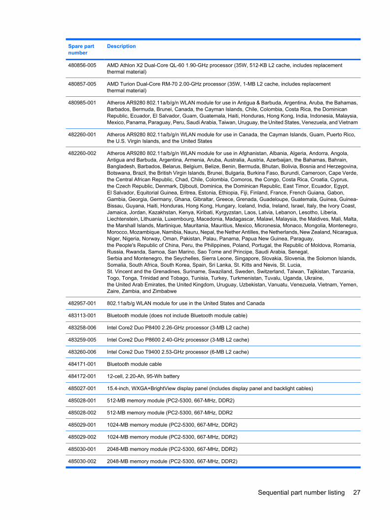
Spare partnumber
Description
480856-005 AMD Athlon X2 Dual-Core QL-60 1.90-GHz processor (35W, 512-KB L2 cache, includes replacementthermal material)
480857-005 AMD Turion Dual-Core RM-70 2.00-GHz processor (35W, 1-MB L2 cache, includes replacementthermal material)
480985-001 Atheros AR9280 802.11a/b/g/n WLAN module for use in Antigua & Barbuda, Argentina, Aruba, the Bahamas,Barbados, Bermuda, Brunei, Canada, the Cayman Islands, Chile, Colombia, Costa Rica, the DominicanRepublic, Ecuador, El Salvador, Guam, Guatemala, Haiti, Honduras, Hong Kong, India, Indonesia, Malaysia,Mexico, Panama, Paraguay, Peru, Saudi Arabia, Taiwan, Uruguay, the United States, Venezuela, and Vietnam
482260-001 Atheros AR9280 802.11a/b/g/n WLAN module for use in Canada, the Cayman Islands, Guam, Puerto Rico,the U.S. Virgin Islands, and the United States
482260-002 Atheros AR9280 802.11a/b/g/n WLAN module for use in Afghanistan, Albania, Algeria, Andorra, Angola,Antigua and Barbuda, Argentina, Armenia, Aruba, Australia, Austria, Azerbaijan, the Bahamas, Bahrain,Bangladesh, Barbados, Belarus, Belgium, Belize, Benin, Bermuda, Bhutan, Bolivia, Bosnia and Herzegovina,Botswana, Brazil, the British Virgin Islands, Brunei, Bulgaria, Burkina Faso, Burundi, Cameroon, Cape Verde,the Central African Republic, Chad, Chile, Colombia, Comoros, the Congo, Costa Rica, Croatia, Cyprus,the Czech Republic, Denmark, Djibouti, Dominica, the Dominican Republic, East Timor, Ecuador, Egypt,El Salvador, Equitorial Guinea, Eritrea, Estonia, Ethiopia, Fiji, Finland, France, French Guiana, Gabon,Gambia, Georgia, Germany, Ghana, Gibraltar, Greece, Grenada, Guadeloupe, Guatemala, Guinea, Guinea-Bissau, Guyana, Haiti, Honduras, Hong Kong, Hungary, Iceland, India, Ireland, Israel, Italy, the Ivory Coast,Jamaica, Jordan, Kazakhstan, Kenya, Kiribati, Kyrgyzstan, Laos, Latvia, Lebanon, Lesotho, Liberia,Liechtenstein, Lithuania, Luxembourg, Macedonia, Madagascar, Malawi, Malaysia, the Maldives, Mali, Malta,the Marshall Islands, Martinique, Mauritania, Mauritius, Mexico, Micronesia, Monaco, Mongolia, Montenegro,Morocco, Mozambique, Namibia, Nauru, Nepal, the Nether Antilles, the Netherlands, New Zealand, Nicaragua,Niger, Nigeria, Norway, Oman, Pakistan, Palau, Panama, Papua New Guinea, Paraguay,the People's Republic of China, Peru, the Philippines, Poland, Portugal, the Republic of Moldova, Romania,Russia, Rwanda, Samoa, San Marino, Sao Tome and Principe, Saudi Arabia, Senegal,Serbia and Montenegro, the Seychelles, Sierra Leone, Singapore, Slovakia, Slovenia, the Solomon Islands,Somalia, South Africa, South Korea, Spain, Sri Lanka, St. Kitts and Nevis, St. Lucia,St. Vincent and the Grenadines, Suriname, Swaziland, Sweden, Switzerland, Taiwan, Tajikistan, Tanzania,Togo, Tonga, Trinidad and Tobago, Tunisia, Turkey, Turkmenistan, Tuvalu, Uganda, Ukraine,the United Arab Emirates, the United Kingdom, Uruguay, Uzbekistan, Vanuatu, Venezuela, Vietnam, Yemen,Zaire, Zambia, and Zimbabwe
482957-001 802.11a/b/g WLAN module for use in the United States and Canada
483113-001 Bluetooth module (does not include Bluetooth module cable)
483258-006 Intel Core2 Duo P8400 2.26-GHz processor (3-MB L2 cache)
483259-005 Intel Core2 Duo P8600 2.40-GHz processor (3-MB L2 cache)
483260-006 Intel Core2 Duo T9400 2.53-GHz processor (6-MB L2 cache)
484171-001 Bluetooth module cable
484172-001 12-cell, 2.20-Ah, 95-Wh battery
485027-001 15.4-inch, WXGA+BrightView display panel (includes display panel and backlight cables)
485028-001 512-MB memory module (PC2-5300, 667-MHz, DDR2)
485028-002 512-MB memory module (PC2-5300, 667-MHz, DDR2
485029-001 1024-MB memory module (PC2-5300, 667-MHz, DDR2)
485029-002 1024-MB memory module (PC2-5300, 667-MHz, DDR2)
485030-001 2048-MB memory module (PC2-5300, 667-MHz, DDR2)
485030-002 2048-MB memory module (PC2-5300, 667-MHz, DDR2)
Sequential part number listing 27
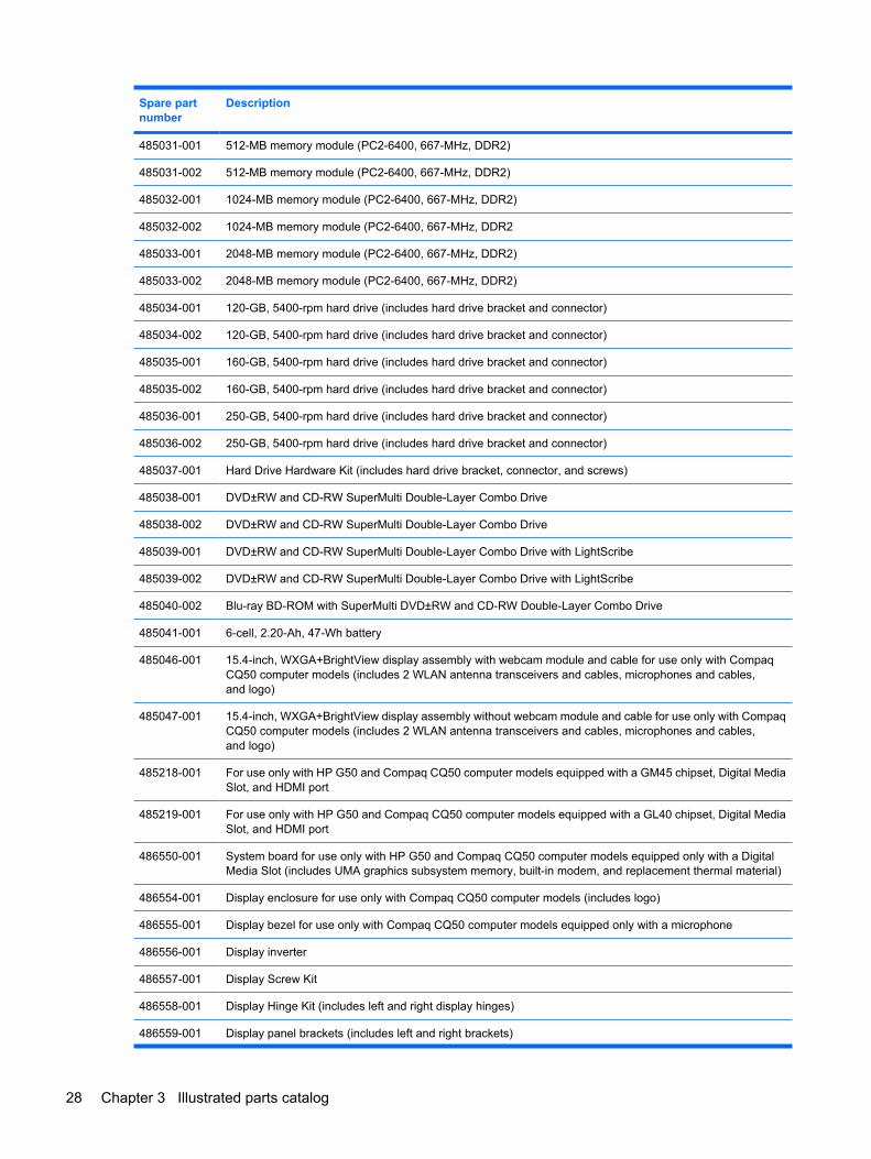
Spare partnumber
Description
485031-001 512-MB memory module (PC2-6400, 667-MHz, DDR2)
485031-002 512-MB memory module (PC2-6400, 667-MHz, DDR2)
485032-001 1024-MB memory module (PC2-6400, 667-MHz, DDR2)
485032-002 1024-MB memory module (PC2-6400, 667-MHz, DDR2
485033-001 2048-MB memory module (PC2-6400, 667-MHz, DDR2)
485033-002 2048-MB memory module (PC2-6400, 667-MHz, DDR2)
485034-001 120-GB, 5400-rpm hard drive (includes hard drive bracket and connector)
485034-002 120-GB, 5400-rpm hard drive (includes hard drive bracket and connector)
485035-001 160-GB, 5400-rpm hard drive (includes hard drive bracket and connector)
485035-002 160-GB, 5400-rpm hard drive (includes hard drive bracket and connector)
485036-001 250-GB, 5400-rpm hard drive (includes hard drive bracket and connector)
485036-002 250-GB, 5400-rpm hard drive (includes hard drive bracket and connector)
485037-001 Hard Drive Hardware Kit (includes hard drive bracket, connector, and screws)
485038-001 DVD±RW and CD-RW SuperMulti Double-Layer Combo Drive
485038-002 DVD±RW and CD-RW SuperMulti Double-Layer Combo Drive
485039-001 DVD±RW and CD-RW SuperMulti Double-Layer Combo Drive with LightScribe
485039-002 DVD±RW and CD-RW SuperMulti Double-Layer Combo Drive with LightScribe
485040-002 Blu-ray BD-ROM with SuperMulti DVD±RW and CD-RW Double-Layer Combo Drive
485041-001 6-cell, 2.20-Ah, 47-Wh battery
485046-001 15.4-inch, WXGA+BrightView display assembly with webcam module and cable for use only with CompaqCQ50 computer models (includes 2 WLAN antenna transceivers and cables, microphones and cables,and logo)
485047-001 15.4-inch, WXGA+BrightView display assembly without webcam module and cable for use only with CompaqCQ50 computer models (includes 2 WLAN antenna transceivers and cables, microphones and cables,and logo)
485218-001 For use only with HP G50 and Compaq CQ50 computer models equipped with a GM45 chipset, Digital MediaSlot, and HDMI port
485219-001 For use only with HP G50 and Compaq CQ50 computer models equipped with a GL40 chipset, Digital MediaSlot, and HDMI port
486550-001 System board for use only with HP G50 and Compaq CQ50 computer models equipped only with a DigitalMedia Slot (includes UMA graphics subsystem memory, built-in modem, and replacement thermal material)
486554-001 Display enclosure for use only with Compaq CQ50 computer models (includes logo)
486555-001 Display bezel for use only with Compaq CQ50 computer models equipped only with a microphone
486556-001 Display inverter
486557-001 Display Screw Kit
486558-001 Display Hinge Kit (includes left and right display hinges)
486559-001 Display panel brackets (includes left and right brackets)
28 Chapter 3 Illustrated parts catalog
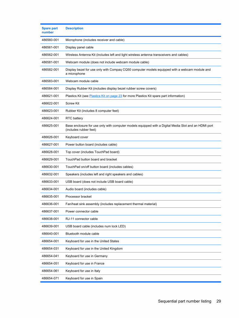
Spare partnumber
Description
486560-001 Microphone (includes receiver and cable)
486561-001 Display panel cable
486562-001 Wireless Antenna Kit (includes left and light wireless antenna transceivers and cables)
486581-001 Webcam module (does not include webcam module cable)
486582-001 Display bezel for use only with Compaq CQ50 computer models equipped with a webcam module anda microphone
486583-001 Webcam module cable
486584-001 Display Rubber Kit (includes display bezel rubber screw covers)
486621-001 Plastics Kit (see Plastics Kit on page 23 for more Plastics Kit spare part information)
486622-001 Screw Kit
486623-001 Rubber Kit (includes 8 computer feet)
486624-001 RTC battery
486625-001 Base enclosure for use only with computer models equipped with a Digital Media Slot and an HDMI port(includes rubber feet)
486626-001 Keyboard cover
486627-001 Power button board (includes cable)
486628-001 Top cover (includes TouchPad board)
486629-001 TouchPad button board and bracket
486630-001 TouchPad on/off button board (includes cables)
486632-001 Speakers (includes left and right speakers and cables)
486633-001 USB board (does not include USB board cable)
486634-001 Audio board (includes cable)
486635-001 Processor bracket
486636-001 Fan/heat sink assembly (includes replacement thermal material)
486637-001 Power connector cable
486638-001 RJ-11 connector cable
486639-001 USB board cable (includes num lock LED)
486640-001 Bluetooth module cable
486654-001 Keyboard for use in the United States
486654-031 Keyboard for use in the United Kingdom
486654-041 Keyboard for use in Germany
486654-051 Keyboard for use in France
486654-061 Keyboard for use in Italy
486654-071 Keyboard for use in Spain
Sequential part number listing 29
Spare partnumber
Description
486654-111 Keyboard for use in Switzerland
486654-121 Keyboard for use in Canada
486654-131 Keyboard for use in Portugal
486654-141 Keyboard for use in Turkey
486654-151 Keyboard for use in Greece
486654-161 Keyboard for use in Latin America
486654-171 Keyboard for use in Saudi Arabia
486654-221 Keyboard for use in the Czech Republic
486654-251 Keyboard for use in Russia
486654-281 Keyboard for use in Thailand
486654-A41 Keyboard for use in Belgium
486654-AB1 Keyboard for use in Taiwan
486654-AD1 Keyboard for use in South Korea
486654-B31 Keyboard for use in the Netherlands
486654-BB1 Keyboard for use in Israel
486654-DH1 Keyboard for use in Denmark, Finland, and Norway
487350-003 AMD Sempron Single Core SI-40 2.0-GHz processor (25W, 512-KB L2 cache, includes replacementthermal material)
487602-001 15.4-inch, WXGA+BrightView display assembly without webcam module and cable for use only with HP G50computer models (includes 2 WLAN antenna transceivers and cables, microphones and cables, and logo)
487603-001 15.4-inch, WXGA+BrightView display assembly with webcam module and cable for use only with HP G50computer models (includes 2 WLAN antenna transceivers and cables, microphones and cables, and logo)
487605-001 Display enclosure for use only with Compaq CQ50 computer models (includes logo)
487606-001 Display bezel for use only with HP G50 computer models equipped only with a microphone
487607-001 Display bezel for use only with HP G50 computer models equipped with a webcam module and a microphone
488338-001 For use only with HP G50 and Compaq CQ50 computer models equipped with NVIDIA GeForce 9200Mgraphics, a Digital Media Slot, and an HDMI port
488341–001 15.4-inch, WXGA+BrightView display panel only (does not include cables)
489133–001 Display screw kit
489157-006 Intel Core2 Duo T9600 2.80-GHz processor (6-MB L2 cache)
489810-001 System board for use only with HP G50 and Compaq CQ50 computer models equipped with a Digital MediaSlot and an HDMI port (includes UMA graphics subsystem memory, built-in modem, and replacementthermal material)
490371-001 Power cord for use in the United States
490371-011 Power cord for use in Australia
490371-021 Power cord for use in Europe
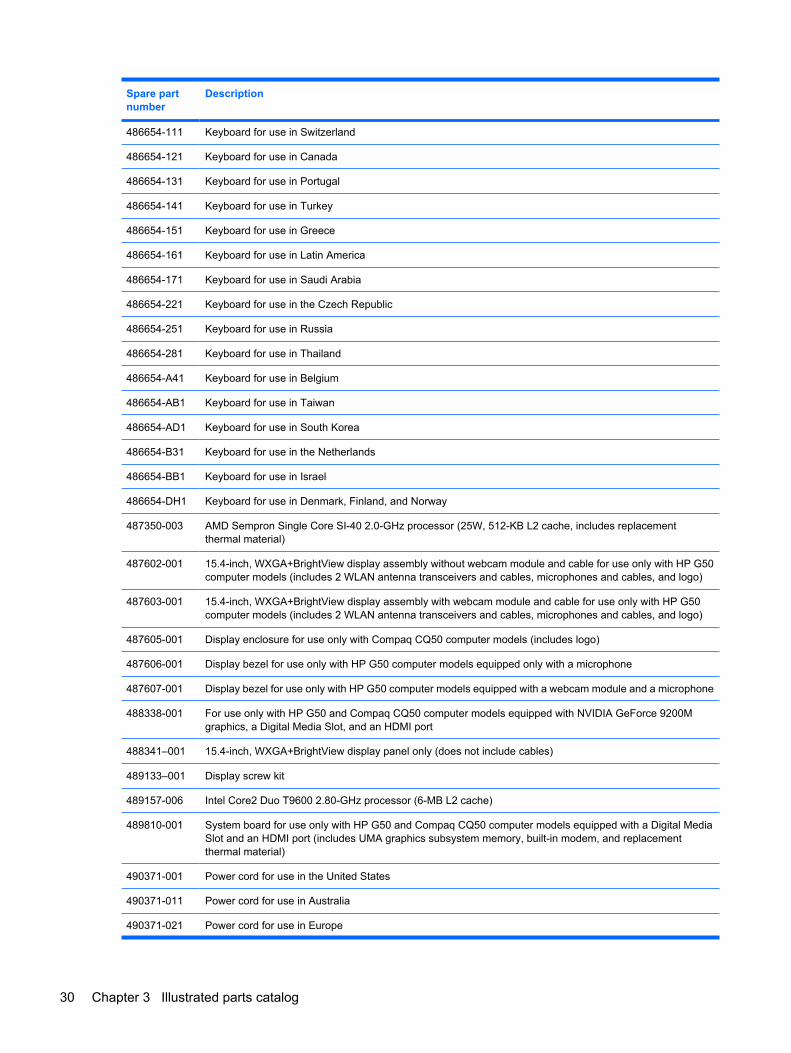
30 Chapter 3 Illustrated parts catalog
Spare partnumber
Description
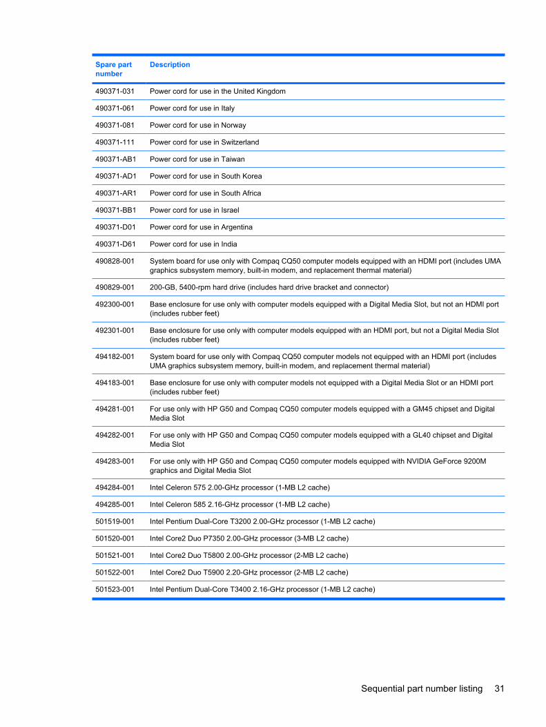
490371-031 Power cord for use in the United Kingdom
490371-061 Power cord for use in Italy
490371-081 Power cord for use in Norway
490371-111 Power cord for use in Switzerland
490371-AB1 Power cord for use in Taiwan
490371-AD1 Power cord for use in South Korea
490371-AR1 Power cord for use in South Africa
490371-BB1 Power cord for use in Israel
490371-D01 Power cord for use in Argentina
490371-D61 Power cord for use in India
490828-001 System board for use only with Compaq CQ50 computer models equipped with an HDMI port (includes UMAgraphics subsystem memory, built-in modem, and replacement thermal material)
490829-001 200-GB, 5400-rpm hard drive (includes hard drive bracket and connector)
492300-001 Base enclosure for use only with computer models equipped with a Digital Media Slot, but not an HDMI port(includes rubber feet)
492301-001 Base enclosure for use only with computer models equipped with an HDMI port, but not a Digital Media Slot(includes rubber feet)
494182-001 System board for use only with Compaq CQ50 computer models not equipped with an HDMI port (includesUMA graphics subsystem memory, built-in modem, and replacement thermal material)
494183-001 Base enclosure for use only with computer models not equipped with a Digital Media Slot or an HDMI port(includes rubber feet)
494281-001 For use only with HP G50 and Compaq CQ50 computer models equipped with a GM45 chipset and DigitalMedia Slot
494282-001 For use only with HP G50 and Compaq CQ50 computer models equipped with a GL40 chipset and DigitalMedia Slot
494283-001 For use only with HP G50 and Compaq CQ50 computer models equipped with NVIDIA GeForce 9200Mgraphics and Digital Media Slot
494284-001 Intel Celeron 575 2.00-GHz processor (1-MB L2 cache)
494285-001 Intel Celeron 585 2.16-GHz processor (1-MB L2 cache)
501519-001 Intel Pentium Dual-Core T3200 2.00-GHz processor (1-MB L2 cache)
501520-001 Intel Core2 Duo P7350 2.00-GHz processor (3-MB L2 cache)
501521-001 Intel Core2 Duo T5800 2.00-GHz processor (2-MB L2 cache)
501522-001 Intel Core2 Duo T5900 2.20-GHz processor (2-MB L2 cache)
501523-001 Intel Pentium Dual-Core T3400 2.16-GHz processor (1-MB L2 cache)
Sequential part number listing 31
4 Removal and replacement procedures
Preliminary replacement requirementsTools required
You will need the following tools to complete the removal and replacement procedures:
● Flat-bladed screwdriver
● Magnetic screwdriver
● Phillips P0 and P1 screwdrivers
Service considerationsThe following sections include some of the considerations that you must keep in mind duringdisassembly and assembly procedures.
NOTE: As you remove each subassembly from the computer, place the subassembly (and allaccompanying screws) away from the work area to prevent damage.
Plastic partsUsing excessive force during disassembly and reassembly can damage plastic parts. Use care whenhandling the plastic parts. Apply pressure only at the points designated in the maintenance instructions.
32 Chapter 4 Removal and replacement procedures
Cables and connectorsCAUTION: When servicing the computer, be sure that cables are placed in their proper locationsduring the reassembly process. Improper cable placement can damage the computer.
Cables must be handled with extreme care to avoid damage. Apply only the tension required to unseator seat the cables during removal and insertion. Handle cables by the connector whenever possible. Inall cases, avoid bending, twisting, or tearing cables. Be sure that cables are routed in such a way thatthey cannot be caught or snagged by parts being removed or replaced. Handle flex cables with extremecare; these cables tear easily.
Drive handlingCAUTION: Drives are fragile components that must be handled with care. To prevent damage to thecomputer, damage to a drive, or loss of information, observe these precautions:
Before removing or inserting a hard drive, shut down the computer. If you are unsure whether thecomputer is off or in Hibernation, turn the computer on, and then shut it down through the operatingsystem.
Before handling a drive, be sure that you are discharged of static electricity. While handling a drive,avoid touching the connector.
Before removing a diskette drive or optical drive, be sure that a diskette or disc is not in the drive andbe sure that the optical drive tray is closed.
Handle drives on surfaces covered with at least one inch of shock-proof foam.
Avoid dropping drives from any height onto any surface.
After removing a hard drive, an optical drive, or a diskette drive, place it in a static-proof bag.
Avoid exposing a hard drive to products that have magnetic fields, such as monitors or speakers.
Avoid exposing a drive to temperature extremes or liquids.
If a drive must be mailed, place the drive in a bubble pack mailer or other suitable form of protectivepackaging and label the package “FRAGILE.”
Preliminary replacement requirements 33
Grounding guidelines
Electrostatic discharge damageElectronic components are sensitive to electrostatic discharge (ESD). Circuitry design and structuredetermine the degree of sensitivity. Networks built into many integrated circuits provide some protection,but in many cases, ESD contains enough power to alter device parameters or melt silicon junctions.
A discharge of static electricity from a finger or other conductor can destroy static-sensitive devices ormicrocircuitry. Even if the spark is neither felt nor heard, damage may have occurred.
An electronic device exposed to ESD may not be affected at all and can work perfectly throughout anormal cycle. Or the device may function normally for a while, then degrade in the internal layers,reducing its life expectancy.
CAUTION: To prevent damage to the computer when you are removing or installing internalcomponents, observe these precautions:
Keep components in their electrostatic-safe containers until you are ready to install them.
Use nonmagnetic tools.
Before touching an electronic component, discharge static electricity by using the guidelines describedin this section.
Avoid touching pins, leads, and circuitry. Handle electronic components as little as possible.
If you remove a component, place it in an electrostatic-safe container.
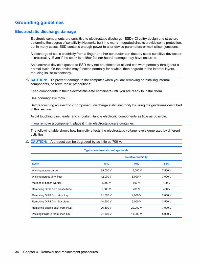
The following table shows how humidity affects the electrostatic voltage levels generated by differentactivities.
CAUTION: A product can be degraded by as little as 700 V.
Typical electrostatic voltage levels
Relative humidity
Event 10% 40% 55%
Walking across carpet 35,000 V 15,000 V 7,500 V
Walking across vinyl floor 12,000 V 5,000 V 3,000 V
Motions of bench worker 6,000 V 800 V 400 V
Removing DIPS from plastic tube 2,000 V 700 V 400 V
Removing DIPS from vinyl tray 11,500 V 4,000 V 2,000 V
Removing DIPS from Styrofoam 14,500 V 5,000 V 3,500 V
Removing bubble pack from PCB 26,500 V 20,000 V 7,000 V
Packing PCBs in foam-lined box 21,000 V 11,000 V 5,000 V
34 Chapter 4 Removal and replacement procedures
Packaging and transporting guidelines
Follow these grounding guidelines when packaging and transporting equipment:
● To avoid hand contact, transport products in static-safe tubes, bags, or boxes.
● Protect ESD-sensitive parts and assemblies with conductive or approved containers or packaging.
● Keep ESD-sensitive parts in their containers until the parts arrive at static-free workstations.
● Place items on a grounded surface before removing items from their containers.
● Always be properly grounded when touching a component or assembly.
● Store reusable ESD-sensitive parts from assemblies in protective packaging or nonconductivefoam.
● Use transporters and conveyors made of antistatic belts and roller bushings. Be sure thatmechanized equipment used for moving materials is wired to ground and that proper materials areselected to avoid static charging. When grounding is not possible, use an ionizer to dissipateelectric charges.
Workstation guidelines
Follow these grounding workstation guidelines:
● Cover the workstation with approved static-shielding material.
● Use a wrist strap connected to a properly grounded work surface and use properly grounded toolsand equipment.
● Use conductive field service tools, such as cutters, screwdrivers, and vacuums.
● When fixtures must directly contact dissipative surfaces, use fixtures made only of static-safematerials.
● Keep the work area free of nonconductive materials, such as ordinary plastic assembly aids andStyrofoam.
● Handle ESD-sensitive components, parts, and assemblies by the case or PCM laminate. Handlethese items only at static-free workstations.
● Avoid contact with pins, leads, or circuitry.
● Turn off power and input signals before inserting or removing connectors or test equipment.
Preliminary replacement requirements 35
Equipment guidelines
Grounding equipment must include either a wrist strap or a foot strap at a grounded workstation.
● When seated, wear a wrist strap connected to a grounded system. Wrist straps are flexible strapswith a minimum of one megohm ±10% resistance in the ground cords. To provide proper ground,wear a strap snugly against the skin at all times. On grounded mats with banana-plug connectors,use alligator clips to connect a wrist strap.
● When standing, use foot straps and a grounded floor mat. Foot straps (heel, toe, or boot straps)can be used at standing workstations and are compatible with most types of shoes or boots. Onconductive floors or dissipative floor mats, use foot straps on both feet with a minimum of onemegohm resistance between the operator and ground. To be effective, the conductive strips mustbe worn in contact with the skin.
The following grounding equipment is recommended to prevent electrostatic damage:
● Antistatic tape
● Antistatic smocks, aprons, and sleeve protectors
● Conductive bins and other assembly or soldering aids
● Nonconductive foam
● Conductive tabletop workstations with ground cords of one megohm resistance
● Static-dissipative tables or floor mats with hard ties to the ground
● Field service kits
● Static awareness labels
● Material-handling packages
● Nonconductive plastic bags, tubes, or boxes
● Metal tote boxes
● Electrostatic voltage levels and protective materials
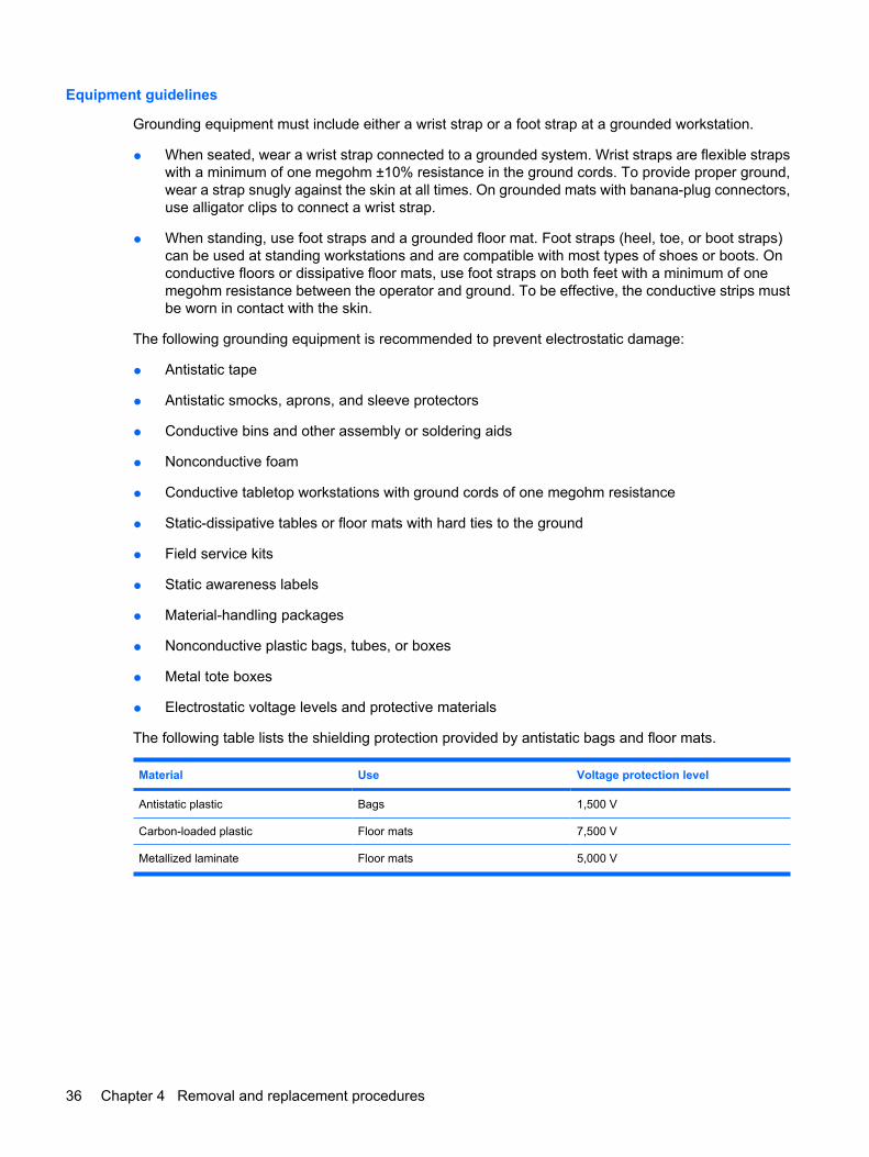
The following table lists the shielding protection provided by antistatic bags and floor mats.
Material Use Voltage protection level
Antistatic plastic Bags 1,500 V
Carbon-loaded plastic Floor mats 7,500 V
Metallized laminate Floor mats 5,000 V
36 Chapter 4 Removal and replacement procedures
Unknown user passwordIf the computer you are servicing has an unknown user password, follow these steps to clear thepassword:
NOTE: These steps also clear CMOS.
1. Shut down the computer. If you are unsure whether the computer is off or in Hibernation, turn thecomputer on, and then shut it down through the operating system.
2. Disconnect all external devices connected to the computer.
3. Disconnect the power from the computer by first unplugging the power cord from the AC outlet andthen unplugging the AC adapter from the computer.
4. Remove the battery (see Battery on page 40).
5. Remove the real-time clock (RTC) battery (see RTC battery on page 46).
6. Wait approximately 5 minutes.
7. Replace the RTC battery and reassemble the computer.
8. Connect AC power to the computer. Do not reinsert any batteries at this time.
9. Turn on the computer.
All passwords and all CMOS settings have been cleared.
Preliminary replacement requirements 37
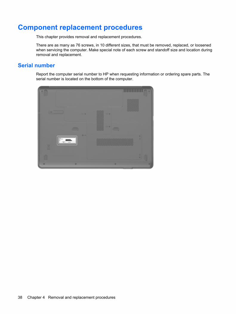
Component replacement proceduresThis chapter provides removal and replacement procedures.
There are as many as 76 screws, in 10 different sizes, that must be removed, replaced, or loosenedwhen servicing the computer. Make special note of each screw and standoff size and location duringremoval and replacement.
Serial numberReport the computer serial number to HP when requesting information or ordering spare parts. Theserial number is located on the bottom of the computer.
38 Chapter 4 Removal and replacement procedures
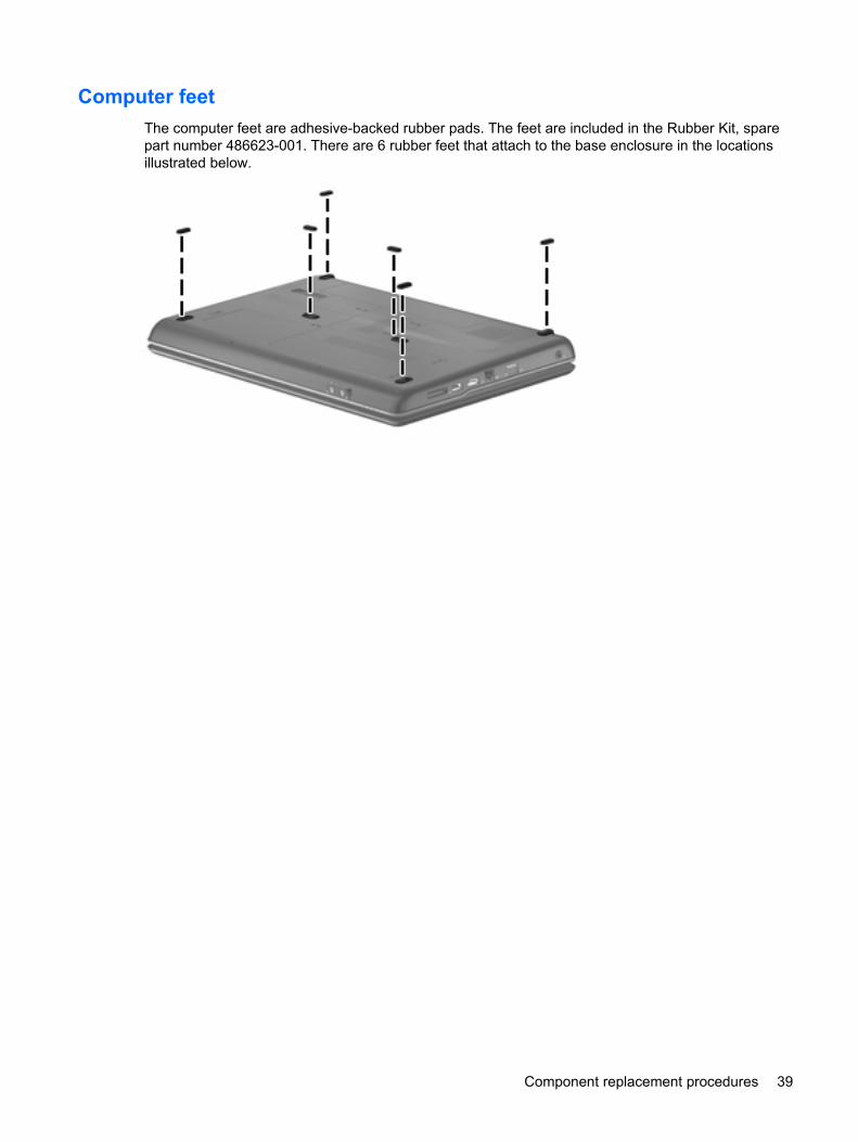
Computer feetThe computer feet are adhesive-backed rubber pads. The feet are included in the Rubber Kit, sparepart number 486623-001. There are 6 rubber feet that attach to the base enclosure in the locationsillustrated below.
Component replacement procedures 39
Battery
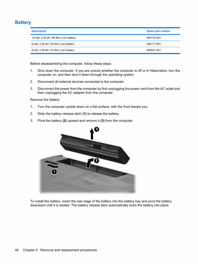
Description Spare part number
12-cell, 2.20-Ah, 95-Wh Li-ion battery 484172-001
6-cell, 2.55-Ah, 55-Wh Li-ion battery 484171-001
6-cell, 2.20-Ah, 47-Wh Li-ion battery 485041-001
Before disassembling the computer, follow these steps:
1. Shut down the computer. If you are unsure whether the computer is off or in Hibernation, turn thecomputer on, and then shut it down through the operating system.
2. Disconnect all external devices connected to the computer.
3. Disconnect the power from the computer by first unplugging the power cord from the AC outlet andthen unplugging the AC adapter from the computer.
Remove the battery:
1. Turn the computer upside down on a flat surface, with the front toward you.
2. Slide the battery release latch (1) to release the battery.
3. Pivot the battery (2) upward and remove it (3) from the computer.
To install the battery, insert the rear edge of the battery into the battery bay and pivot the batterydownward until it is seated. The battery release latch automatically locks the battery into place.
40 Chapter 4 Removal and replacement procedures
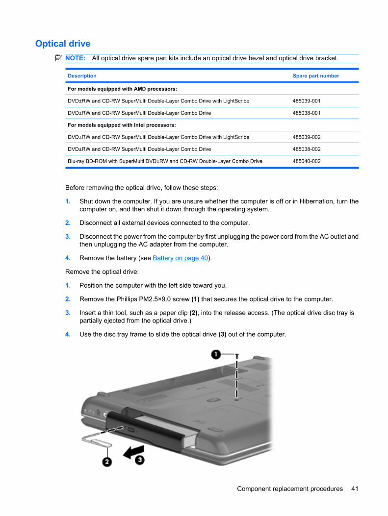
Optical driveNOTE: All optical drive spare part kits include an optical drive bezel and optical drive bracket.
Description Spare part number
For models equipped with AMD processors:
DVD±RW and CD-RW SuperMulti Double-Layer Combo Drive with LightScribe 485039-001
DVD±RW and CD-RW SuperMulti Double-Layer Combo Drive 485038-001
For models equipped with Intel processors:
DVD±RW and CD-RW SuperMulti Double-Layer Combo Drive with LightScribe 485039-002
DVD±RW and CD-RW SuperMulti Double-Layer Combo Drive 485038-002
Blu-ray BD-ROM with SuperMulti DVD±RW and CD-RW Double-Layer Combo Drive 485040-002
Before removing the optical drive, follow these steps:
1. Shut down the computer. If you are unsure whether the computer is off or in Hibernation, turn thecomputer on, and then shut it down through the operating system.
2. Disconnect all external devices connected to the computer.
3. Disconnect the power from the computer by first unplugging the power cord from the AC outlet andthen unplugging the AC adapter from the computer.
4. Remove the battery (see Battery on page 40).
Remove the optical drive:
1. Position the computer with the left side toward you.
2. Remove the Phillips PM2.5×9.0 screw (1) that secures the optical drive to the computer.
3. Insert a thin tool, such as a paper clip (2), into the release access. (The optical drive disc tray ispartially ejected from the optical drive.)
4. Use the disc tray frame to slide the optical drive (3) out of the computer.
Component replacement procedures 41
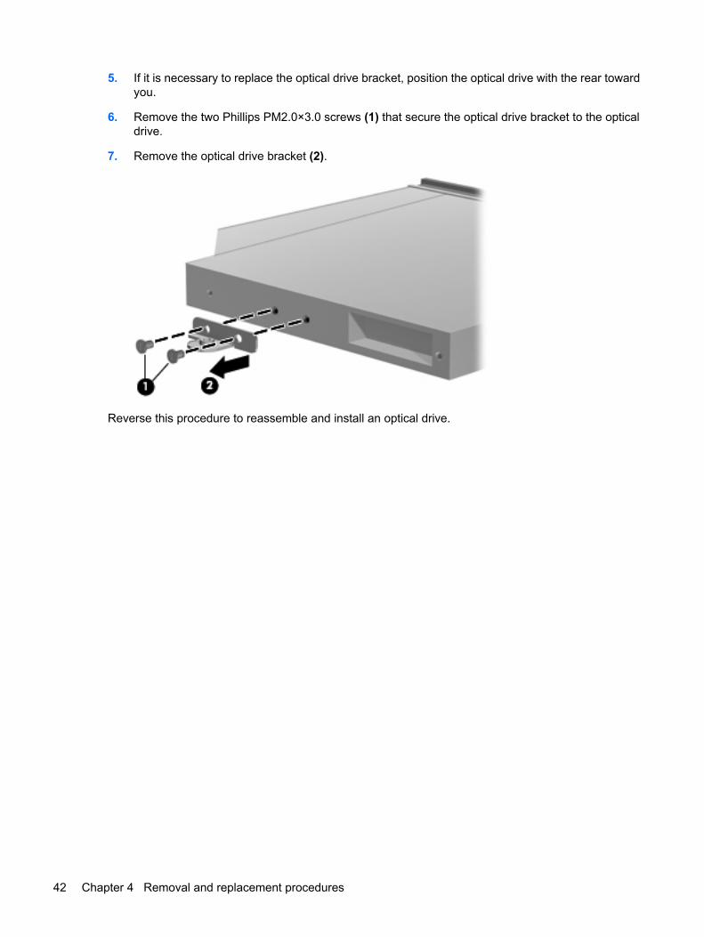
5. If it is necessary to replace the optical drive bracket, position the optical drive with the rear towardyou.
6. Remove the two Phillips PM2.0×3.0 screws (1) that secure the optical drive bracket to the opticaldrive.
7. Remove the optical drive bracket (2).
Reverse this procedure to reassemble and install an optical drive.
42 Chapter 4 Removal and replacement procedures
Hard driveNOTE: All hard drive spare part kits include a hard drive bracket and hard drive connector. The harddrive bracket and hard drive connector, as well as the hard drive bracket screws, are also available inthe Hard Drive Hardware Kit, spare part number 485037-001.
Description Spare part number
For models equipped with AMD processors:
250-GB, 5400-rpm hard drive 485036-001
200-GB, 5400-rpm hard drive 490829-001
160-GB, 5400-rpm hard drive 485035-001
120-GB, 5400-rpm hard drive 485034-001
For models equipped with Intel processors:
250-GB, 5400-rpm hard drive 485036-002
160-GB, 5400-rpm hard drive 485035-002
120-GB, 5400-rpm hard drive 485034-002
Before removing the hard drive, follow these steps:
1. Shut down the computer. If you are unsure whether the computer is off or in Hibernation, turn thecomputer on, and then shut it down through the operating system.
2. Disconnect all external devices connected to the computer.
3. Disconnect the power from the computer by first unplugging the power cord from the AC outlet andthen unplugging the AC adapter from the computer.
4. Remove the battery (see Battery on page 40).
Remove the hard drive:
1. Loosen the two Phillips PM2.5×6.0 captive screws (1) that secure the hard drive cover to thecomputer.
Component replacement procedures 43
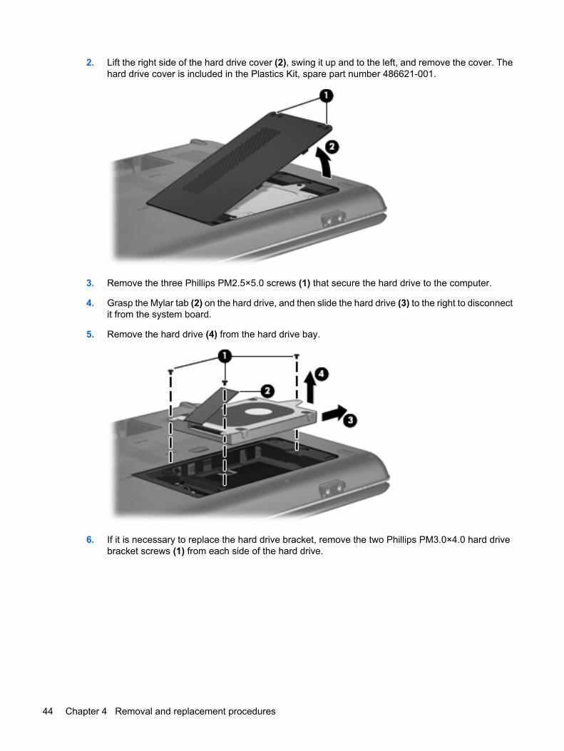
2. Lift the right side of the hard drive cover (2), swing it up and to the left, and remove the cover. Thehard drive cover is included in the Plastics Kit, spare part number 486621-001.
3. Remove the three Phillips PM2.5×5.0 screws (1) that secure the hard drive to the computer.
4. Grasp the Mylar tab (2) on the hard drive, and then slide the hard drive (3) to the right to disconnectit from the system board.
5. Remove the hard drive (4) from the hard drive bay.
6. If it is necessary to replace the hard drive bracket, remove the two Phillips PM3.0×4.0 hard drivebracket screws (1) from each side of the hard drive.
44 Chapter 4 Removal and replacement procedures
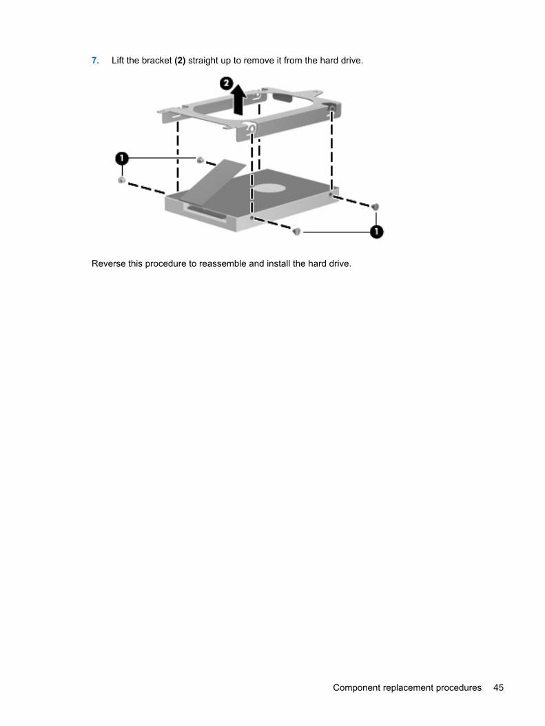
7. Lift the bracket (2) straight up to remove it from the hard drive.
Reverse this procedure to reassemble and install the hard drive.
Component replacement procedures 45
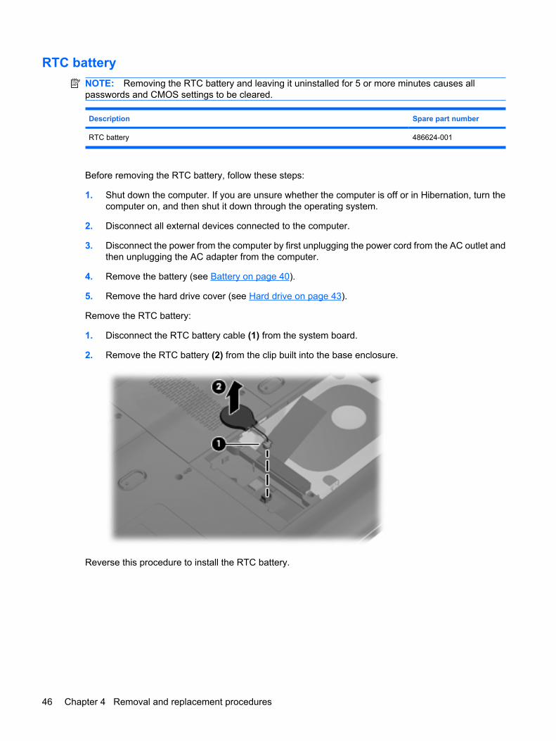
RTC batteryNOTE: Removing the RTC battery and leaving it uninstalled for 5 or more minutes causes allpasswords and CMOS settings to be cleared.
Description Spare part number
RTC battery 486624-001
Before removing the RTC battery, follow these steps:
1. Shut down the computer. If you are unsure whether the computer is off or in Hibernation, turn thecomputer on, and then shut it down through the operating system.
2. Disconnect all external devices connected to the computer.
3. Disconnect the power from the computer by first unplugging the power cord from the AC outlet andthen unplugging the AC adapter from the computer.
4. Remove the battery (see Battery on page 40).
5. Remove the hard drive cover (see Hard drive on page 43).
Remove the RTC battery:
1. Disconnect the RTC battery cable (1) from the system board.
2. Remove the RTC battery (2) from the clip built into the base enclosure.
Reverse this procedure to install the RTC battery.
46 Chapter 4 Removal and replacement procedures
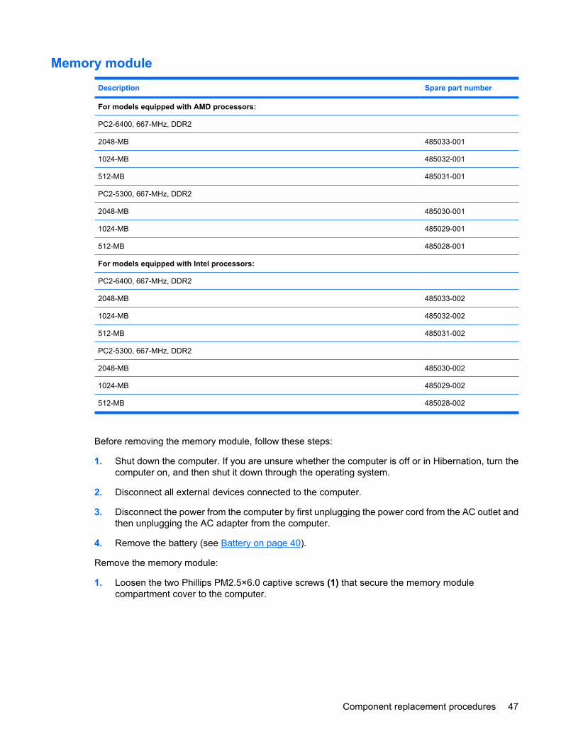
Memory module
Description Spare part number
For models equipped with AMD processors:
PC2-6400, 667-MHz, DDR2
2048-MB 485033-001
1024-MB 485032-001
512-MB 485031-001
PC2-5300, 667-MHz, DDR2
2048-MB 485030-001
1024-MB 485029-001
512-MB 485028-001
For models equipped with Intel processors:
PC2-6400, 667-MHz, DDR2
2048-MB 485033-002
1024-MB 485032-002
512-MB 485031-002
PC2-5300, 667-MHz, DDR2
2048-MB 485030-002
1024-MB 485029-002
512-MB 485028-002
Before removing the memory module, follow these steps:
1. Shut down the computer. If you are unsure whether the computer is off or in Hibernation, turn thecomputer on, and then shut it down through the operating system.
2. Disconnect all external devices connected to the computer.
3. Disconnect the power from the computer by first unplugging the power cord from the AC outlet andthen unplugging the AC adapter from the computer.
4. Remove the battery (see Battery on page 40).
Remove the memory module:
1. Loosen the two Phillips PM2.5×6.0 captive screws (1) that secure the memory modulecompartment cover to the computer.
Component replacement procedures 47
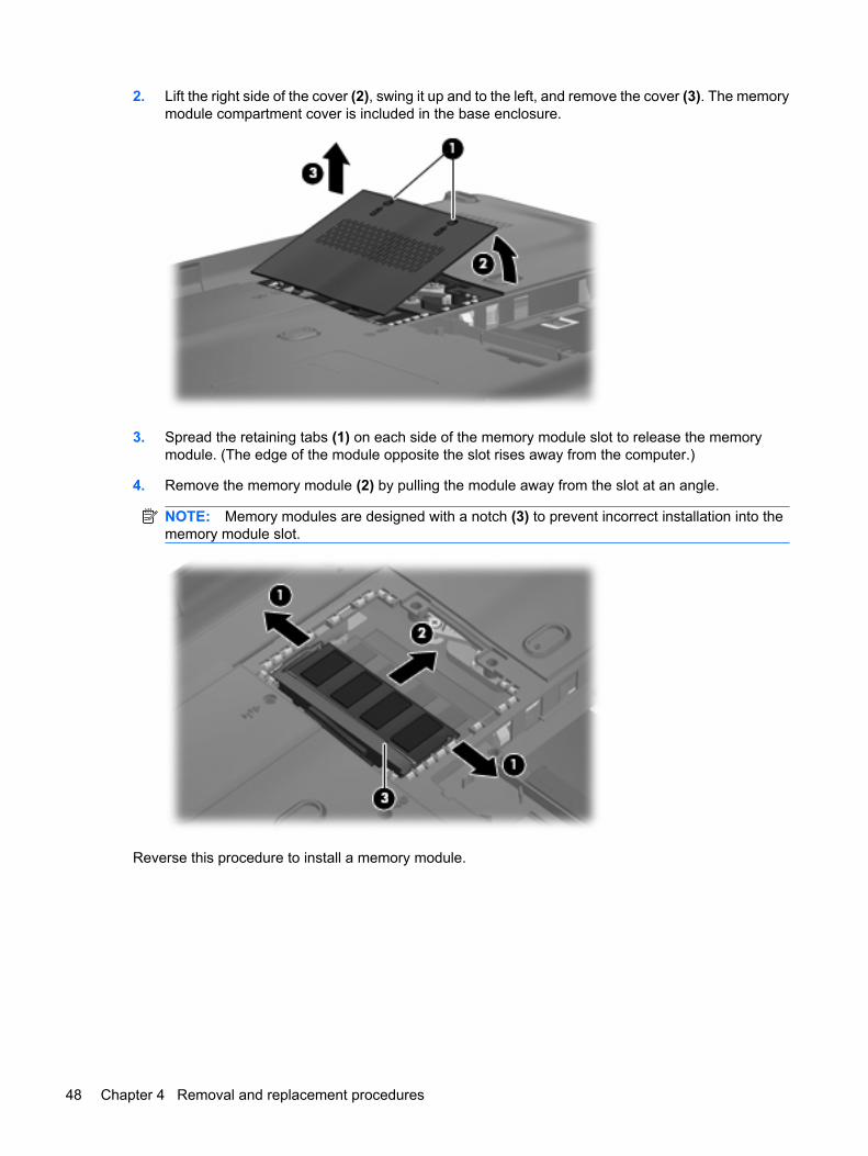
2. Lift the right side of the cover (2), swing it up and to the left, and remove the cover (3). The memorymodule compartment cover is included in the base enclosure.
3. Spread the retaining tabs (1) on each side of the memory module slot to release the memorymodule. (The edge of the module opposite the slot rises away from the computer.)
4. Remove the memory module (2) by pulling the module away from the slot at an angle.
NOTE: Memory modules are designed with a notch (3) to prevent incorrect installation into thememory module slot.
Reverse this procedure to install a memory module.
48 Chapter 4 Removal and replacement procedures
WLAN module
Description Spare part number
Atheros AR9280 802.11a/b/g/n WLAN modules:
For use in Canada, the Cayman Islands, Guam, Puerto Rico, the U.S. Virgin Islands,and the United States
482260-001
For use in Afghanistan, Albania, Algeria, Andorra, Angola, Antigua and Barbuda, Argentina,Armenia, Aruba, Australia, Austria, Azerbaijan, the Bahamas, Bahrain, Bangladesh, Barbados,Belarus, Belgium, Belize, Benin, Bermuda, Bhutan, Bolivia, Bosnia and Herzegovina, Botswana,Brazil, the British Virgin Islands, Brunei, Bulgaria, Burkina Faso, Burundi, Cameroon, Cape Verde,the Central African Republic, Chad, Chile, Colombia, Comoros, the Congo, Costa Rica, Croatia,Cyprus, the Czech Republic, Denmark, Djibouti, Dominica, the Dominican Republic, East Timor,Ecuador, Egypt, El Salvador, Equitorial Guinea, Eritrea, Estonia, Ethiopia, Fiji, Finland, France,French Guiana, Gabon, Gambia, Georgia, Germany, Ghana, Gibraltar, Greece, Grenada,Guadeloupe, Guatemala, Guinea, Guinea-Bissau, Guyana, Haiti, Honduras, Hong Kong,Hungary, Iceland, India, Ireland, Israel, Italy, the Ivory Coast, Jamaica, Jordan, Kazakhstan,Kenya, Kiribati, Kyrgyzstan, Laos, Latvia, Lebanon, Lesotho, Liberia, Liechtenstein, Lithuania,Luxembourg, Macedonia, Madagascar, Malawi, Malaysia, the Maldives, Mali, Malta,the Marshall Islands, Martinique, Mauritania, Mauritius, Mexico, Micronesia, Monaco, Mongolia,Montenegro, Morocco, Mozambique, Namibia, Nauru, Nepal, the Nether Antilles,the Netherlands, New Zealand, Nicaragua, Niger, Nigeria, Norway, Oman, Pakistan, Palau,Panama, Papua New Guinea, Paraguay, the People's Republic of China, Peru, the Philippines,Poland, Portugal, the Republic of Moldova, Romania, Russia, Rwanda, Samoa, San Marino,Sao Tome and Principe, Saudi Arabia, Senegal, Serbia and Montenegro, the Seychelles,Sierra Leone, Singapore, Slovakia, Slovenia, the Solomon Islands, Somalia, South Africa,South Korea, Spain, Sri Lanka, St. Kitts and Nevis, St. Lucia, St. Vincent and the Grenadines,Suriname, Swaziland, Sweden, Switzerland, Taiwan, Tajikistan, Tanzania, Togo, Tonga,Trinidad and Tobago, Tunisia, Turkey, Turkmenistan, Tuvalu, Uganda, Ukraine,the United Arab Emirates, the United Kingdom, Uruguay, Uzbekistan, Vanuatu, Venezuela,Vietnam, Yemen, Zaire, Zambia, and Zimbabwe
482260-002
For use in Antigua & Barbuda, Argentina, Aruba, the Bahamas, Barbados, Bermuda, Brunei,Canada, the Cayman Islands, Chile, Colombia, Costa Rica, the Dominican Republic, Ecuador, ElSalvador, Guam, Guatemala, Haiti, Honduras, Hong Kong, India, Indonesia, Malaysia, Mexico,Panama, Paraguay, Peru, Saudi Arabia, Taiwan, Uruguay, the United States, Venezuela, andVietnam
480985-001
Broadcom BCM4312 802.11b/g WLAN modules:
For use in Canada, the Cayman Islands, Guam, Puerto Rico, the U.S. Virgin Islands,and the United States
459263-001
For use in Afghanistan, Albania, Algeria, Andorra, Angola, Antigua and Barbuda, Argentina,Armenia, Aruba, Australia, Austria, Azerbaijan, the Bahamas, Bahrain, Bangladesh, Barbados,Belarus, Belgium, Belize, Benin, Bermuda, Bhutan, Bolivia, Bosnia and Herzegovina, Botswana,Brazil, the British Virgin Islands, Brunei, Bulgaria, Burkina Faso, Burundi, Cameroon, Cape Verde,the Central African Republic, Chad, Chile, Colombia, Comoros, the Congo, Costa Rica, Croatia,Cyprus, the Czech Republic, Denmark, Djibouti, Dominica, the Dominican Republic, East Timor,Ecuador, Egypt, El Salvador, Equitorial Guinea, Eritrea, Estonia, Ethiopia, Fiji, Finland, France,French Guiana, Gabon, Gambia, Georgia, Germany, Ghana, Gibraltar, Greece, Grenada,Guadeloupe, Guatemala, Guinea, Guinea-Bissau, Guyana, Haiti, Honduras, Hong Kong,Hungary, Iceland, India, Ireland, Israel, Italy, the Ivory Coast, Jamaica, Jordan, Kazakhstan,Kenya, Kiribati, Kyrgyzstan, Laos, Latvia, Lebanon, Lesotho, Liberia, Liechtenstein, Lithuania,Luxembourg, Macedonia, Madagascar, Malawi, Malaysia, the Maldives, Mali, Malta,the Marshall Islands, Martinique, Mauritania, Mauritius, Mexico, Micronesia, Monaco, Mongolia,Montenegro, Morocco, Mozambique, Namibia, Nauru, Nepal, the Nether Antilles,the Netherlands, New Zealand, Nicaragua, Niger, Nigeria, Norway, Oman, Pakistan, Palau,Panama, Papua New Guinea, Paraguay, the People's Republic of China, Peru, the Philippines,Poland, Portugal, the Republic of Moldova, Romania, Russia, Rwanda, Samoa, San Marino,Sao Tome and Principe, Saudi Arabia, Senegal, Serbia and Montenegro, the Seychelles,Sierra Leone, Singapore, Slovakia, Slovenia, the Solomon Islands, Somalia, South Africa,South Korea, Spain, Sri Lanka, St. Kitts and Nevis, St. Lucia, St. Vincent and the Grenadines,
459263-002
Component replacement procedures 49
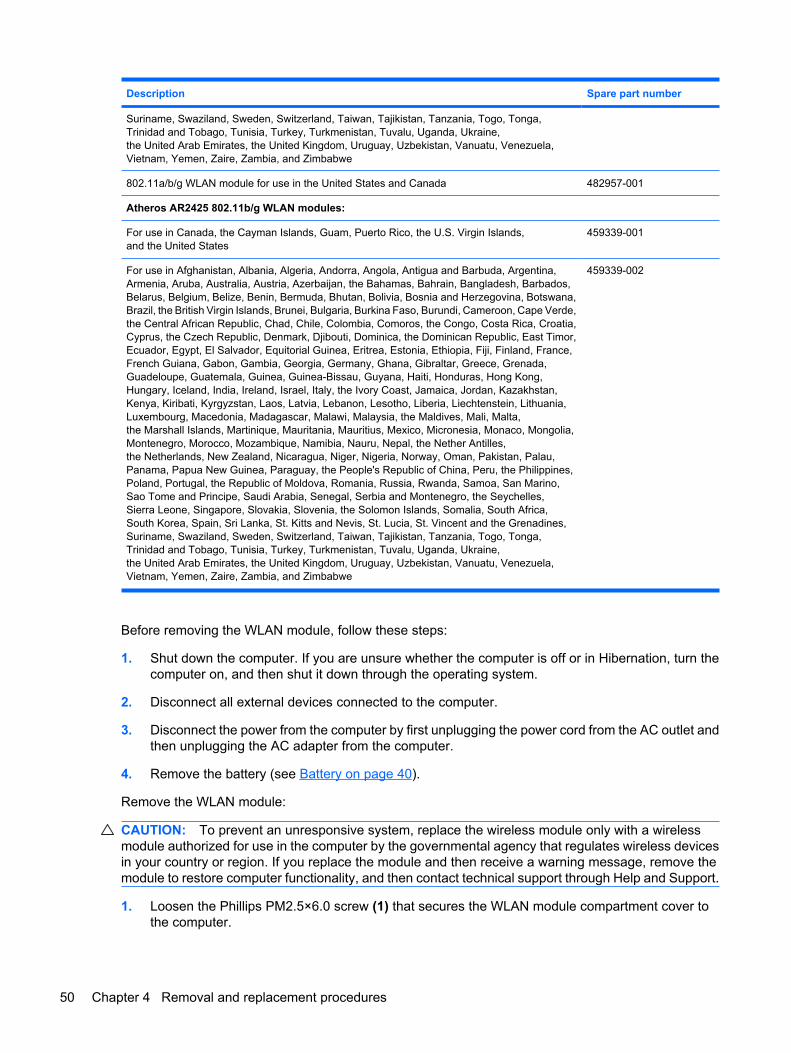
Description Spare part number
Suriname, Swaziland, Sweden, Switzerland, Taiwan, Tajikistan, Tanzania, Togo, Tonga,Trinidad and Tobago, Tunisia, Turkey, Turkmenistan, Tuvalu, Uganda, Ukraine,the United Arab Emirates, the United Kingdom, Uruguay, Uzbekistan, Vanuatu, Venezuela,Vietnam, Yemen, Zaire, Zambia, and Zimbabwe
802.11a/b/g WLAN module for use in the United States and Canada 482957-001
Atheros AR2425 802.11b/g WLAN modules:
For use in Canada, the Cayman Islands, Guam, Puerto Rico, the U.S. Virgin Islands,and the United States
459339-001
For use in Afghanistan, Albania, Algeria, Andorra, Angola, Antigua and Barbuda, Argentina,Armenia, Aruba, Australia, Austria, Azerbaijan, the Bahamas, Bahrain, Bangladesh, Barbados,Belarus, Belgium, Belize, Benin, Bermuda, Bhutan, Bolivia, Bosnia and Herzegovina, Botswana,Brazil, the British Virgin Islands, Brunei, Bulgaria, Burkina Faso, Burundi, Cameroon, Cape Verde,the Central African Republic, Chad, Chile, Colombia, Comoros, the Congo, Costa Rica, Croatia,Cyprus, the Czech Republic, Denmark, Djibouti, Dominica, the Dominican Republic, East Timor,Ecuador, Egypt, El Salvador, Equitorial Guinea, Eritrea, Estonia, Ethiopia, Fiji, Finland, France,French Guiana, Gabon, Gambia, Georgia, Germany, Ghana, Gibraltar, Greece, Grenada,Guadeloupe, Guatemala, Guinea, Guinea-Bissau, Guyana, Haiti, Honduras, Hong Kong,Hungary, Iceland, India, Ireland, Israel, Italy, the Ivory Coast, Jamaica, Jordan, Kazakhstan,Kenya, Kiribati, Kyrgyzstan, Laos, Latvia, Lebanon, Lesotho, Liberia, Liechtenstein, Lithuania,Luxembourg, Macedonia, Madagascar, Malawi, Malaysia, the Maldives, Mali, Malta,the Marshall Islands, Martinique, Mauritania, Mauritius, Mexico, Micronesia, Monaco, Mongolia,Montenegro, Morocco, Mozambique, Namibia, Nauru, Nepal, the Nether Antilles,the Netherlands, New Zealand, Nicaragua, Niger, Nigeria, Norway, Oman, Pakistan, Palau,Panama, Papua New Guinea, Paraguay, the People's Republic of China, Peru, the Philippines,Poland, Portugal, the Republic of Moldova, Romania, Russia, Rwanda, Samoa, San Marino,Sao Tome and Principe, Saudi Arabia, Senegal, Serbia and Montenegro, the Seychelles,Sierra Leone, Singapore, Slovakia, Slovenia, the Solomon Islands, Somalia, South Africa,South Korea, Spain, Sri Lanka, St. Kitts and Nevis, St. Lucia, St. Vincent and the Grenadines,Suriname, Swaziland, Sweden, Switzerland, Taiwan, Tajikistan, Tanzania, Togo, Tonga,Trinidad and Tobago, Tunisia, Turkey, Turkmenistan, Tuvalu, Uganda, Ukraine,the United Arab Emirates, the United Kingdom, Uruguay, Uzbekistan, Vanuatu, Venezuela,Vietnam, Yemen, Zaire, Zambia, and Zimbabwe
459339-002
Before removing the WLAN module, follow these steps:
1. Shut down the computer. If you are unsure whether the computer is off or in Hibernation, turn thecomputer on, and then shut it down through the operating system.
2. Disconnect all external devices connected to the computer.
3. Disconnect the power from the computer by first unplugging the power cord from the AC outlet andthen unplugging the AC adapter from the computer.
4. Remove the battery (see Battery on page 40).
Remove the WLAN module:
CAUTION: To prevent an unresponsive system, replace the wireless module only with a wirelessmodule authorized for use in the computer by the governmental agency that regulates wireless devicesin your country or region. If you replace the module and then receive a warning message, remove themodule to restore computer functionality, and then contact technical support through Help and Support.
1. Loosen the Phillips PM2.5×6.0 screw (1) that secures the WLAN module compartment cover tothe computer.
50 Chapter 4 Removal and replacement procedures
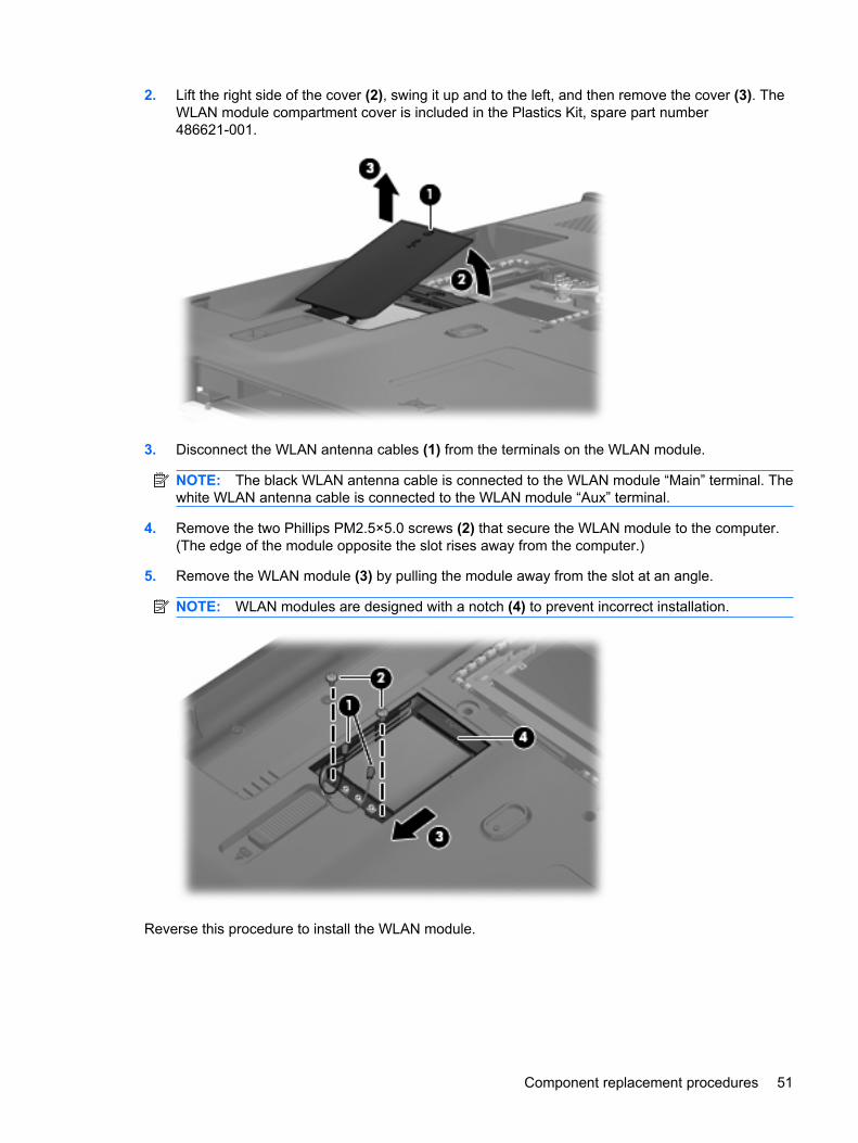
2. Lift the right side of the cover (2), swing it up and to the left, and then remove the cover (3). TheWLAN module compartment cover is included in the Plastics Kit, spare part number486621-001.
3. Disconnect the WLAN antenna cables (1) from the terminals on the WLAN module.
NOTE: The black WLAN antenna cable is connected to the WLAN module “Main” terminal. Thewhite WLAN antenna cable is connected to the WLAN module “Aux” terminal.
4. Remove the two Phillips PM2.5×5.0 screws (2) that secure the WLAN module to the computer.(The edge of the module opposite the slot rises away from the computer.)
5. Remove the WLAN module (3) by pulling the module away from the slot at an angle.
NOTE: WLAN modules are designed with a notch (4) to prevent incorrect installation.
Reverse this procedure to install the WLAN module.
Component replacement procedures 51
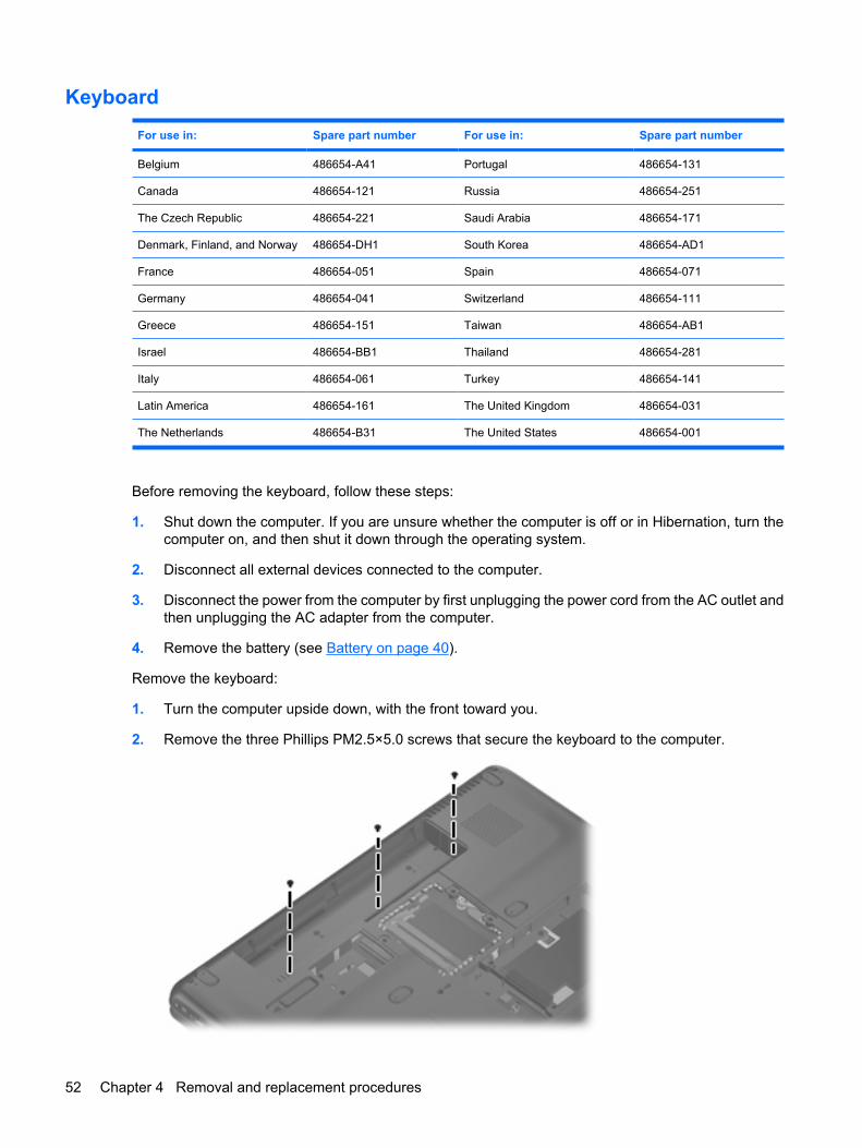
Keyboard
For use in: Spare part number For use in: Spare part number
Belgium 486654-A41 Portugal 486654-131
Canada 486654-121 Russia 486654-251
The Czech Republic 486654-221 Saudi Arabia 486654-171
Denmark, Finland, and Norway 486654-DH1 South Korea 486654-AD1
France 486654-051 Spain 486654-071
Germany 486654-041 Switzerland 486654-111
Greece 486654-151 Taiwan 486654-AB1
Israel 486654-BB1 Thailand 486654-281
Italy 486654-061 Turkey 486654-141
Latin America 486654-161 The United Kingdom 486654-031
The Netherlands 486654-B31 The United States 486654-001
Before removing the keyboard, follow these steps:
1. Shut down the computer. If you are unsure whether the computer is off or in Hibernation, turn thecomputer on, and then shut it down through the operating system.
2. Disconnect all external devices connected to the computer.
3. Disconnect the power from the computer by first unplugging the power cord from the AC outlet andthen unplugging the AC adapter from the computer.
4. Remove the battery (see Battery on page 40).
Remove the keyboard:
1. Turn the computer upside down, with the front toward you.
2. Remove the three Phillips PM2.5×5.0 screws that secure the keyboard to the computer.
52 Chapter 4 Removal and replacement procedures
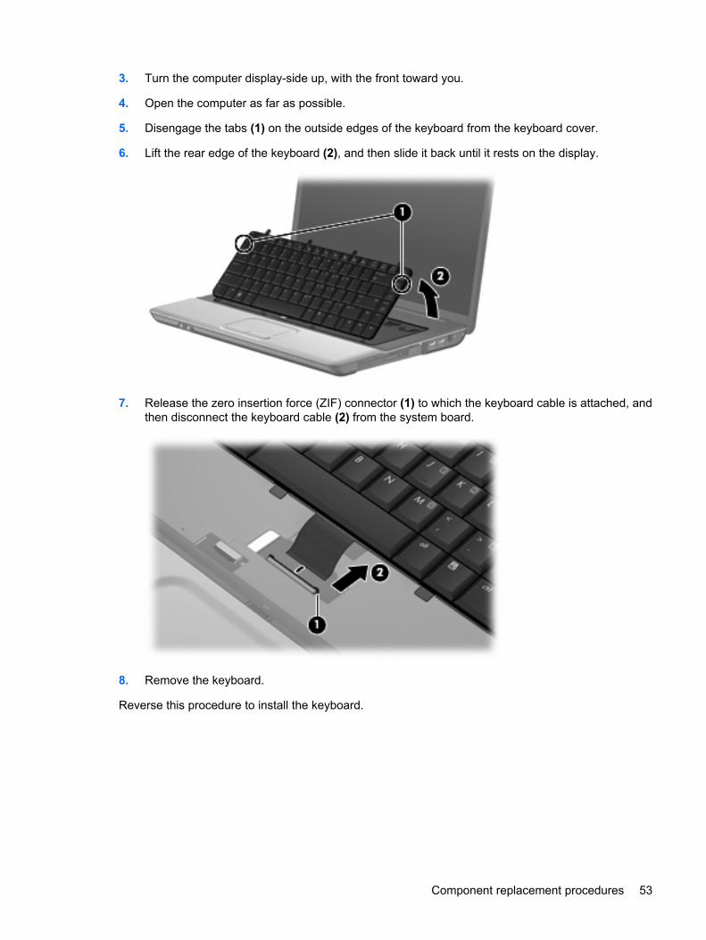
3. Turn the computer display-side up, with the front toward you.
4. Open the computer as far as possible.
5. Disengage the tabs (1) on the outside edges of the keyboard from the keyboard cover.
6. Lift the rear edge of the keyboard (2), and then slide it back until it rests on the display.
7. Release the zero insertion force (ZIF) connector (1) to which the keyboard cable is attached, andthen disconnect the keyboard cable (2) from the system board.
8. Remove the keyboard.
Reverse this procedure to install the keyboard.
Component replacement procedures 53
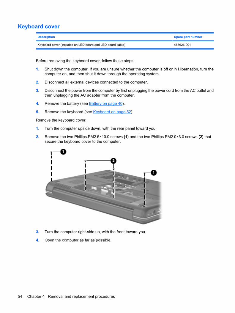
Keyboard cover
Description Spare part number
Keyboard cover (includes an LED board and LED board cable) 486626-001
Before removing the keyboard cover, follow these steps:
1. Shut down the computer. If you are unsure whether the computer is off or in Hibernation, turn thecomputer on, and then shut it down through the operating system.
2. Disconnect all external devices connected to the computer.
3. Disconnect the power from the computer by first unplugging the power cord from the AC outlet andthen unplugging the AC adapter from the computer.
4. Remove the battery (see Battery on page 40).
5. Remove the keyboard (see Keyboard on page 52).
Remove the keyboard cover:
1. Turn the computer upside down, with the rear panel toward you.
2. Remove the two Phillips PM2.5×10.0 screws (1) and the two Phillips PM2.0×3.0 screws (2) thatsecure the keyboard cover to the computer.
3. Turn the computer right-side up, with the front toward you.
4. Open the computer as far as possible.
54 Chapter 4 Removal and replacement procedures
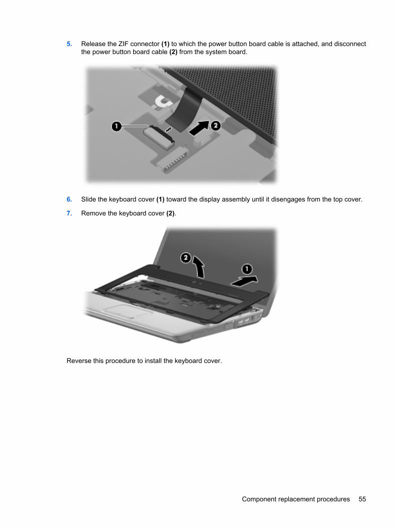
5. Release the ZIF connector (1) to which the power button board cable is attached, and disconnectthe power button board cable (2) from the system board.
6. Slide the keyboard cover (1) toward the display assembly until it disengages from the top cover.
7. Remove the keyboard cover (2).
Reverse this procedure to install the keyboard cover.
Component replacement procedures 55
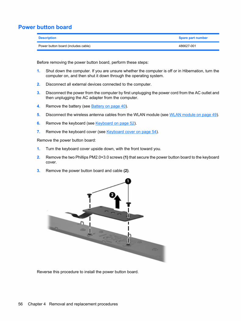
Power button board
Description Spare part number
Power button board (includes cable) 486627-001
Before removing the power button board, perform these steps:
1. Shut down the computer. If you are unsure whether the computer is off or in Hibernation, turn thecomputer on, and then shut it down through the operating system.
2. Disconnect all external devices connected to the computer.
3. Disconnect the power from the computer by first unplugging the power cord from the AC outlet andthen unplugging the AC adapter from the computer.
4. Remove the battery (see Battery on page 40).
5. Disconnect the wireless antenna cables from the WLAN module (see WLAN module on page 49).
6. Remove the keyboard (see Keyboard on page 52).
7. Remove the keyboard cover (see Keyboard cover on page 54).
Remove the power button board:
1. Turn the keyboard cover upside down, with the front toward you.
2. Remove the two Phillips PM2.0×3.0 screws (1) that secure the power button board to the keyboardcover.
3. Remove the power button board and cable (2).
Reverse this procedure to install the power button board.
56 Chapter 4 Removal and replacement procedures
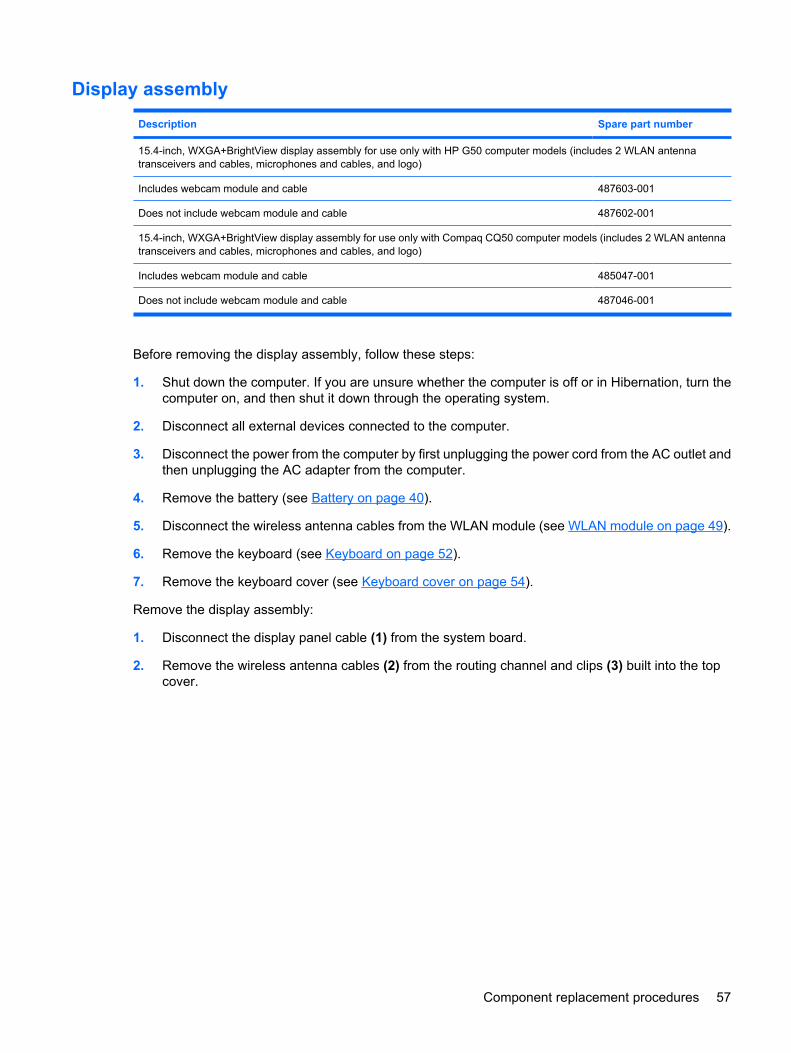
Display assembly
Description Spare part number
15.4-inch, WXGA+BrightView display assembly for use only with HP G50 computer models (includes 2 WLAN antennatransceivers and cables, microphones and cables, and logo)
Includes webcam module and cable 487603-001
Does not include webcam module and cable 487602-001
15.4-inch, WXGA+BrightView display assembly for use only with Compaq CQ50 computer models (includes 2 WLAN antennatransceivers and cables, microphones and cables, and logo)
Includes webcam module and cable 485047-001
Does not include webcam module and cable 487046-001
Before removing the display assembly, follow these steps:
1. Shut down the computer. If you are unsure whether the computer is off or in Hibernation, turn thecomputer on, and then shut it down through the operating system.
2. Disconnect all external devices connected to the computer.
3. Disconnect the power from the computer by first unplugging the power cord from the AC outlet andthen unplugging the AC adapter from the computer.
4. Remove the battery (see Battery on page 40).
5. Disconnect the wireless antenna cables from the WLAN module (see WLAN module on page 49).
6. Remove the keyboard (see Keyboard on page 52).
7. Remove the keyboard cover (see Keyboard cover on page 54).
Remove the display assembly:
1. Disconnect the display panel cable (1) from the system board.
2. Remove the wireless antenna cables (2) from the routing channel and clips (3) built into the topcover.
Component replacement procedures 57
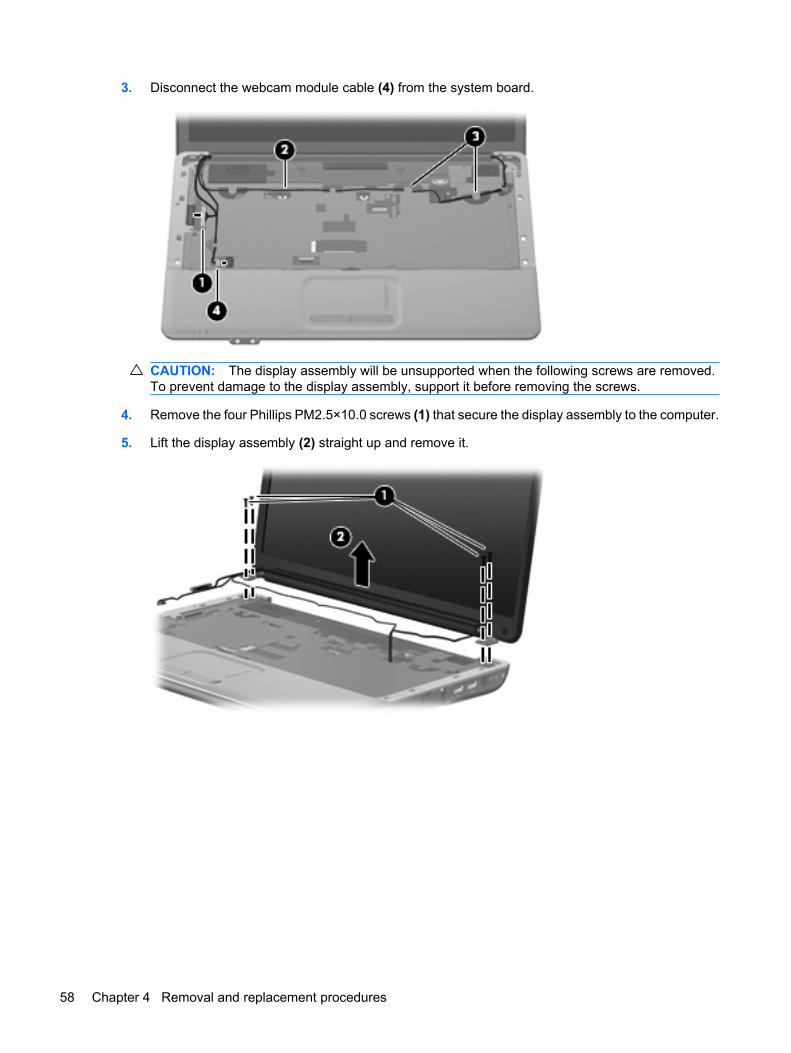
3. Disconnect the webcam module cable (4) from the system board.
CAUTION: The display assembly will be unsupported when the following screws are removed.To prevent damage to the display assembly, support it before removing the screws.
4. Remove the four Phillips PM2.5×10.0 screws (1) that secure the display assembly to the computer.
5. Lift the display assembly (2) straight up and remove it.
58 Chapter 4 Removal and replacement procedures
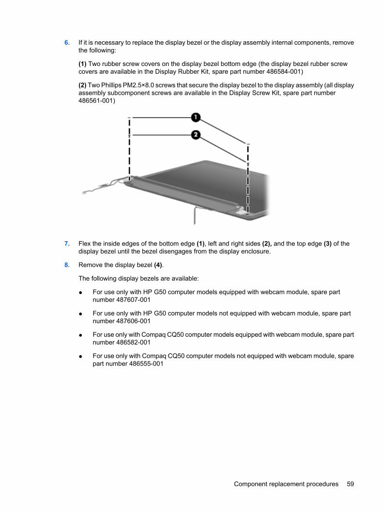
6. If it is necessary to replace the display bezel or the display assembly internal components, removethe following:
(1) Two rubber screw covers on the display bezel bottom edge (the display bezel rubber screwcovers are available in the Display Rubber Kit, spare part number 486584-001)
(2) Two Phillips PM2.5×8.0 screws that secure the display bezel to the display assembly (all displayassembly subcomponent screws are available in the Display Screw Kit, spare part number486561-001)
7. Flex the inside edges of the bottom edge (1), left and right sides (2), and the top edge (3) of thedisplay bezel until the bezel disengages from the display enclosure.
8. Remove the display bezel (4).
The following display bezels are available:
● For use only with HP G50 computer models equipped with webcam module, spare partnumber 487607-001
● For use only with HP G50 computer models not equipped with webcam module, spare partnumber 487606-001
● For use only with Compaq CQ50 computer models equipped with webcam module, spare partnumber 486582-001
● For use only with Compaq CQ50 computer models not equipped with webcam module, sparepart number 486555-001
Component replacement procedures 59
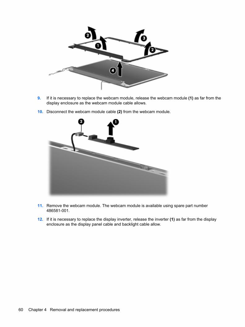
9. If it is necessary to replace the webcam module, release the webcam module (1) as far from thedisplay enclosure as the webcam module cable allows.
10. Disconnect the webcam module cable (2) from the webcam module.
11. Remove the webcam module. The webcam module is available using spare part number486581-001.
12. If it is necessary to replace the display inverter, release the inverter (1) as far from the displayenclosure as the display panel cable and backlight cable allow.
60 Chapter 4 Removal and replacement procedures
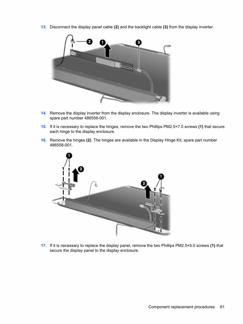
13. Disconnect the display panel cable (2) and the backlight cable (3) from the display inverter.
14. Remove the display inverter from the display enclosure. The display inverter is available usingspare part number 486556-001.
15. If it is necessary to replace the hinges, remove the two Phillips PM2.5×7.0 screws (1) that secureeach hinge to the display enclosure.
16. Remove the hinges (2). The hinges are available in the Display Hinge Kit, spare part number486558-001.
17. If it is necessary to replace the display panel, remove the two Phillips PM2.5×5.0 screws (1) thatsecure the display panel to the display enclosure.
Component replacement procedures 61
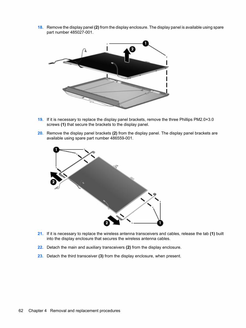
18. Remove the display panel (2) from the display enclosure. The display panel is available using sparepart number 485027-001.
19. If it is necessary to replace the display panel brackets, remove the three Phillips PM2.0×3.0screws (1) that secure the brackets to the display panel.
20. Remove the display panel brackets (2) from the display panel. The display panel brackets areavailable using spare part number 486559-001.
21. If it is necessary to replace the wireless antenna transceivers and cables, release the tab (1) builtinto the display enclosure that secures the wireless antenna cables.
22. Detach the main and auxiliary transceivers (2) from the display enclosure.
23. Detach the third transceiver (3) from the display enclosure, when present.
62 Chapter 4 Removal and replacement procedures
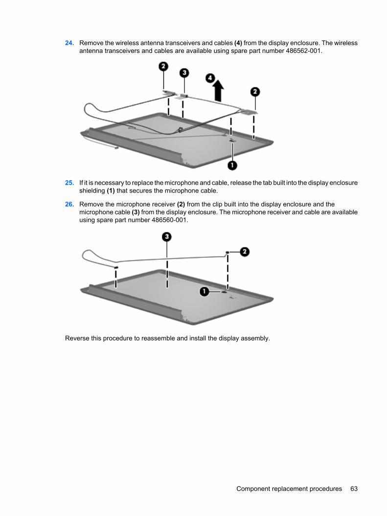
24. Remove the wireless antenna transceivers and cables (4) from the display enclosure. The wirelessantenna transceivers and cables are available using spare part number 486562-001.
25. If it is necessary to replace the microphone and cable, release the tab built into the display enclosureshielding (1) that secures the microphone cable.
26. Remove the microphone receiver (2) from the clip built into the display enclosure and themicrophone cable (3) from the display enclosure. The microphone receiver and cable are availableusing spare part number 486560-001.
Reverse this procedure to reassemble and install the display assembly.
Component replacement procedures 63
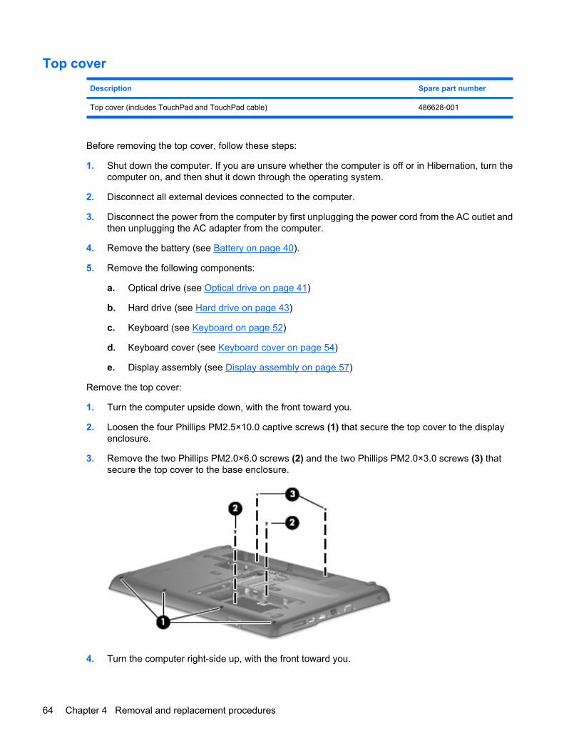
Top cover
Description Spare part number
Top cover (includes TouchPad and TouchPad cable) 486628-001
Before removing the top cover, follow these steps:
1. Shut down the computer. If you are unsure whether the computer is off or in Hibernation, turn thecomputer on, and then shut it down through the operating system.
2. Disconnect all external devices connected to the computer.
3. Disconnect the power from the computer by first unplugging the power cord from the AC outlet andthen unplugging the AC adapter from the computer.
4. Remove the battery (see Battery on page 40).
5. Remove the following components:
a. Optical drive (see Optical drive on page 41)
b. Hard drive (see Hard drive on page 43)
c. Keyboard (see Keyboard on page 52)
d. Keyboard cover (see Keyboard cover on page 54)
e. Display assembly (see Display assembly on page 57)
Remove the top cover:
1. Turn the computer upside down, with the front toward you.
2. Loosen the four Phillips PM2.5×10.0 captive screws (1) that secure the top cover to the displayenclosure.
3. Remove the two Phillips PM2.0×6.0 screws (2) and the two Phillips PM2.0×3.0 screws (3) thatsecure the top cover to the base enclosure.
4. Turn the computer right-side up, with the front toward you.
64 Chapter 4 Removal and replacement procedures
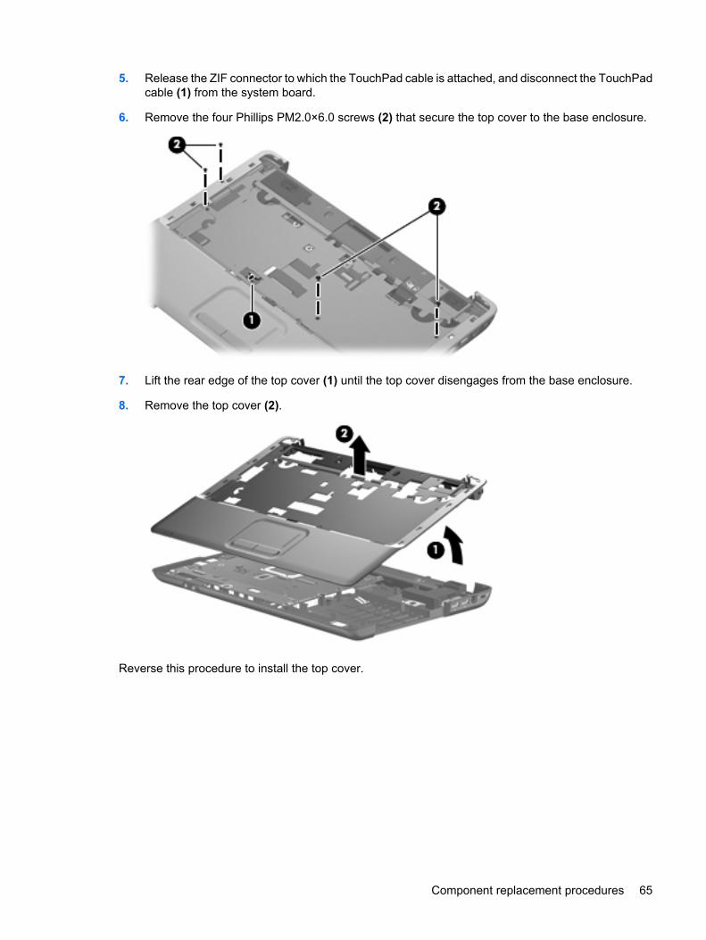
5. Release the ZIF connector to which the TouchPad cable is attached, and disconnect the TouchPadcable (1) from the system board.
6. Remove the four Phillips PM2.0×6.0 screws (2) that secure the top cover to the base enclosure.
7. Lift the rear edge of the top cover (1) until the top cover disengages from the base enclosure.
8. Remove the top cover (2).
Reverse this procedure to install the top cover.
Component replacement procedures 65
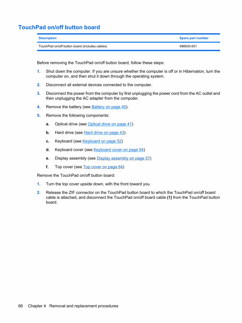
TouchPad on/off button board
Description Spare part number
TouchPad on/off button board (includes cables) 486630-001
Before removing the TouchPad on/off button board, follow these steps:
1. Shut down the computer. If you are unsure whether the computer is off or in Hibernation, turn thecomputer on, and then shut it down through the operating system.
2. Disconnect all external devices connected to the computer.
3. Disconnect the power from the computer by first unplugging the power cord from the AC outlet andthen unplugging the AC adapter from the computer.
4. Remove the battery (see Battery on page 40).
5. Remove the following components:
a. Optical drive (see Optical drive on page 41)
b. Hard drive (see Hard drive on page 43)
c. Keyboard (see Keyboard on page 52)
d. Keyboard cover (see Keyboard cover on page 54)
e. Display assembly (see Display assembly on page 57)
f. Top cover (see Top cover on page 64)
Remove the TouchPad on/off button board:
1. Turn the top cover upside down, with the front toward you.
2. Release the ZIF connector on the TouchPad button board to which the TouchPad on/off boardcable is attached, and disconnect the TouchPad on/off board cable (1) from the TouchPad buttonboard.
66 Chapter 4 Removal and replacement procedures
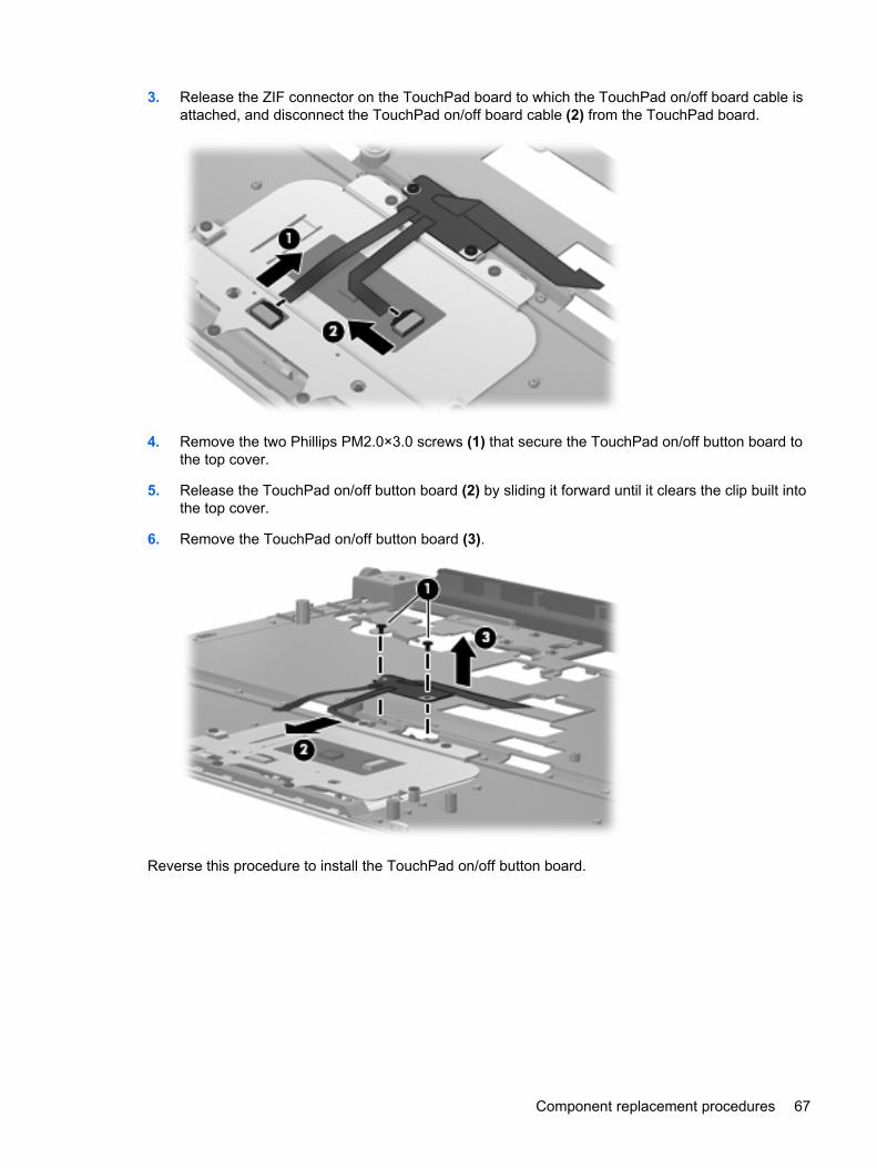
3. Release the ZIF connector on the TouchPad board to which the TouchPad on/off board cable isattached, and disconnect the TouchPad on/off board cable (2) from the TouchPad board.
4. Remove the two Phillips PM2.0×3.0 screws (1) that secure the TouchPad on/off button board tothe top cover.
5. Release the TouchPad on/off button board (2) by sliding it forward until it clears the clip built intothe top cover.
6. Remove the TouchPad on/off button board (3).
Reverse this procedure to install the TouchPad on/off button board.
Component replacement procedures 67
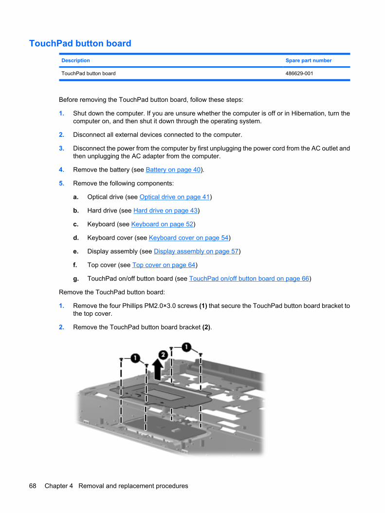
TouchPad button board
Description Spare part number
TouchPad button board 486629-001
Before removing the TouchPad button board, follow these steps:
1. Shut down the computer. If you are unsure whether the computer is off or in Hibernation, turn thecomputer on, and then shut it down through the operating system.
2. Disconnect all external devices connected to the computer.
3. Disconnect the power from the computer by first unplugging the power cord from the AC outlet andthen unplugging the AC adapter from the computer.
4. Remove the battery (see Battery on page 40).
5. Remove the following components:
a. Optical drive (see Optical drive on page 41)
b. Hard drive (see Hard drive on page 43)
c. Keyboard (see Keyboard on page 52)
d. Keyboard cover (see Keyboard cover on page 54)
e. Display assembly (see Display assembly on page 57)
f. Top cover (see Top cover on page 64)
g. TouchPad on/off button board (see TouchPad on/off button board on page 66)
Remove the TouchPad button board:
1. Remove the four Phillips PM2.0×3.0 screws (1) that secure the TouchPad button board bracket tothe top cover.
2. Remove the TouchPad button board bracket (2).
68 Chapter 4 Removal and replacement procedures
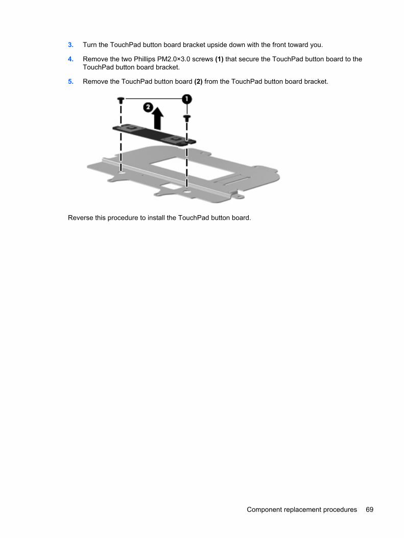
3. Turn the TouchPad button board bracket upside down with the front toward you.
4. Remove the two Phillips PM2.0×3.0 screws (1) that secure the TouchPad button board to theTouchPad button board bracket.
5. Remove the TouchPad button board (2) from the TouchPad button board bracket.
Reverse this procedure to install the TouchPad button board.
Component replacement procedures 69
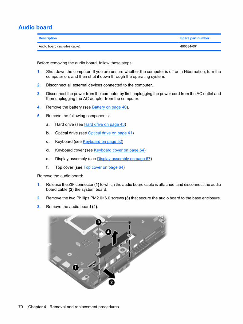
Audio board
Description Spare part number
Audio board (includes cable) 486634-001
Before removing the audio board, follow these steps:
1. Shut down the computer. If you are unsure whether the computer is off or in Hibernation, turn thecomputer on, and then shut it down through the operating system.
2. Disconnect all external devices connected to the computer.
3. Disconnect the power from the computer by first unplugging the power cord from the AC outlet andthen unplugging the AC adapter from the computer.
4. Remove the battery (see Battery on page 40).
5. Remove the following components:
a. Hard drive (see Hard drive on page 43)
b. Optical drive (see Optical drive on page 41)
c. Keyboard (see Keyboard on page 52)
d. Keyboard cover (see Keyboard cover on page 54)
e. Display assembly (see Display assembly on page 57)
f. Top cover (see Top cover on page 64)
Remove the audio board:
1. Release the ZIF connector (1) to which the audio board cable is attached, and disconnect the audioboard cable (2) the system board.
2. Remove the two Phillips PM2.0×6.0 screws (3) that secure the audio board to the base enclosure.
3. Remove the audio board (4).
70 Chapter 4 Removal and replacement procedures
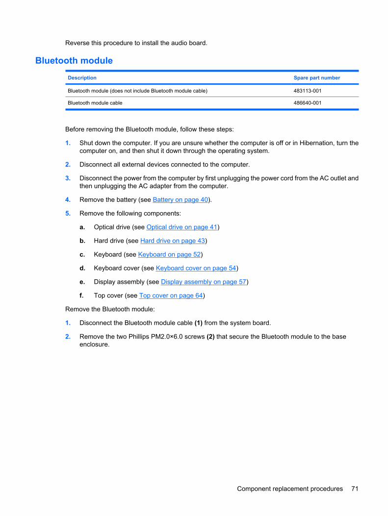
Reverse this procedure to install the audio board.
Bluetooth module
Description Spare part number
Bluetooth module (does not include Bluetooth module cable) 483113-001
Bluetooth module cable 486640-001
Before removing the Bluetooth module, follow these steps:
1. Shut down the computer. If you are unsure whether the computer is off or in Hibernation, turn thecomputer on, and then shut it down through the operating system.
2. Disconnect all external devices connected to the computer.
3. Disconnect the power from the computer by first unplugging the power cord from the AC outlet andthen unplugging the AC adapter from the computer.
4. Remove the battery (see Battery on page 40).
5. Remove the following components:
a. Optical drive (see Optical drive on page 41)
b. Hard drive (see Hard drive on page 43)
c. Keyboard (see Keyboard on page 52)
d. Keyboard cover (see Keyboard cover on page 54)
e. Display assembly (see Display assembly on page 57)
f. Top cover (see Top cover on page 64)
Remove the Bluetooth module:
1. Disconnect the Bluetooth module cable (1) from the system board.
2. Remove the two Phillips PM2.0×6.0 screws (2) that secure the Bluetooth module to the baseenclosure.
Component replacement procedures 71
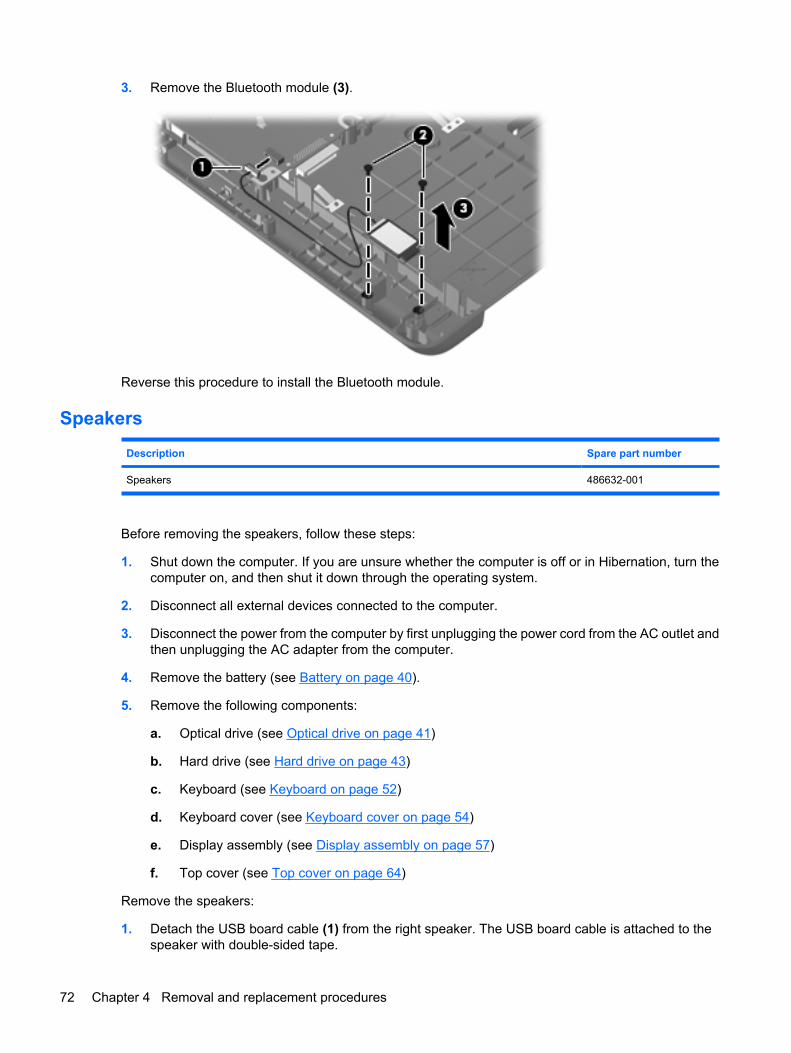
3. Remove the Bluetooth module (3).
Reverse this procedure to install the Bluetooth module.
Speakers
Description Spare part number
Speakers 486632-001
Before removing the speakers, follow these steps:
1. Shut down the computer. If you are unsure whether the computer is off or in Hibernation, turn thecomputer on, and then shut it down through the operating system.
2. Disconnect all external devices connected to the computer.
3. Disconnect the power from the computer by first unplugging the power cord from the AC outlet andthen unplugging the AC adapter from the computer.
4. Remove the battery (see Battery on page 40).
5. Remove the following components:
a. Optical drive (see Optical drive on page 41)
b. Hard drive (see Hard drive on page 43)
c. Keyboard (see Keyboard on page 52)
d. Keyboard cover (see Keyboard cover on page 54)
e. Display assembly (see Display assembly on page 57)
f. Top cover (see Top cover on page 64)
Remove the speakers:
1. Detach the USB board cable (1) from the right speaker. The USB board cable is attached to thespeaker with double-sided tape.
72 Chapter 4 Removal and replacement procedures
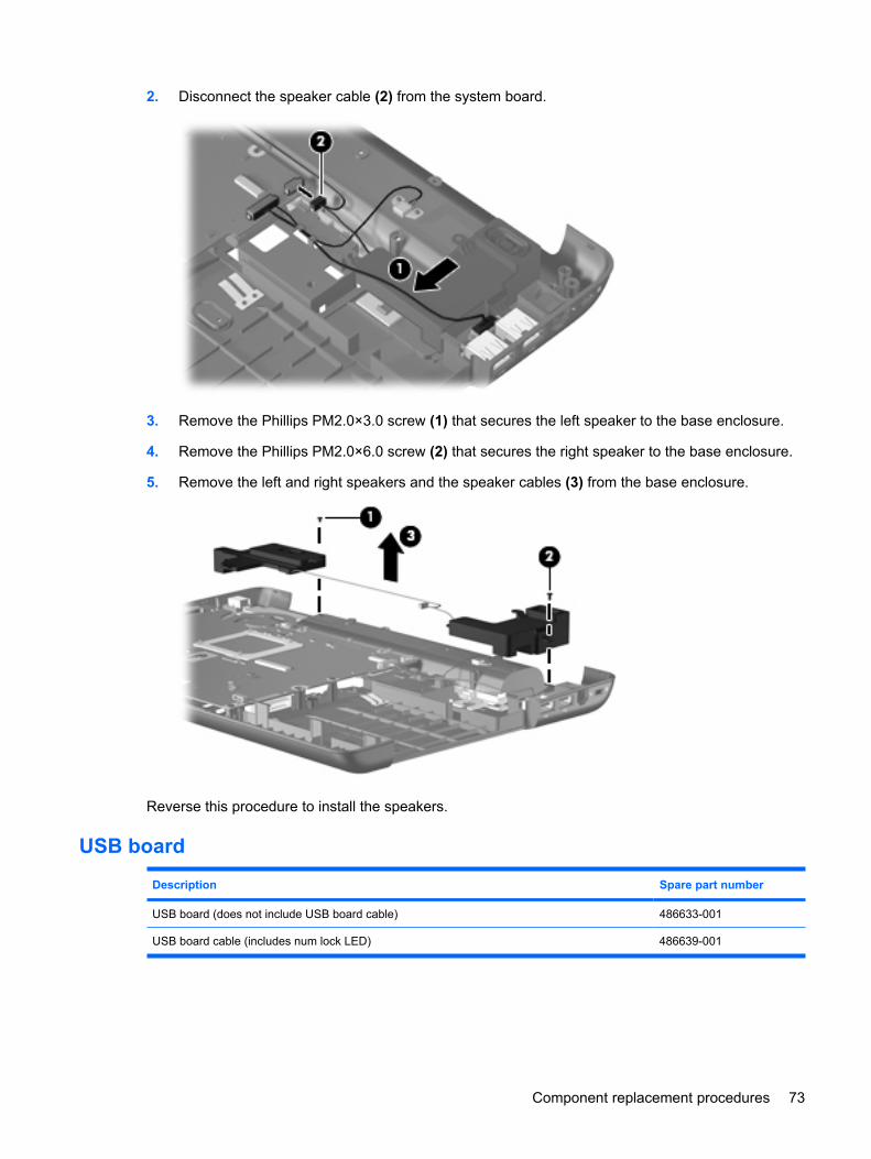
2. Disconnect the speaker cable (2) from the system board.
3. Remove the Phillips PM2.0×3.0 screw (1) that secures the left speaker to the base enclosure.
4. Remove the Phillips PM2.0×6.0 screw (2) that secures the right speaker to the base enclosure.
5. Remove the left and right speakers and the speaker cables (3) from the base enclosure.
Reverse this procedure to install the speakers.
USB board
Description Spare part number
USB board (does not include USB board cable) 486633-001
USB board cable (includes num lock LED) 486639-001
Component replacement procedures 73
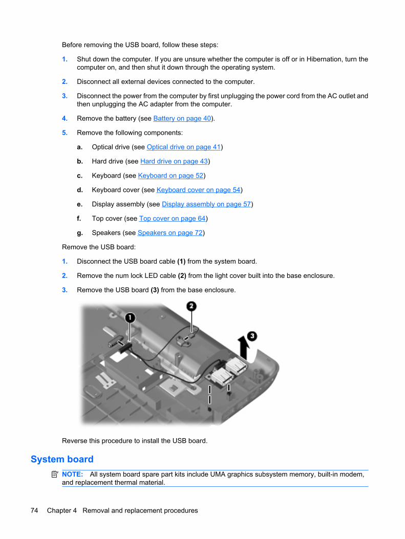
Before removing the USB board, follow these steps:
1. Shut down the computer. If you are unsure whether the computer is off or in Hibernation, turn thecomputer on, and then shut it down through the operating system.
2. Disconnect all external devices connected to the computer.
3. Disconnect the power from the computer by first unplugging the power cord from the AC outlet andthen unplugging the AC adapter from the computer.
4. Remove the battery (see Battery on page 40).
5. Remove the following components:
a. Optical drive (see Optical drive on page 41)
b. Hard drive (see Hard drive on page 43)
c. Keyboard (see Keyboard on page 52)
d. Keyboard cover (see Keyboard cover on page 54)
e. Display assembly (see Display assembly on page 57)
f. Top cover (see Top cover on page 64)
g. Speakers (see Speakers on page 72)
Remove the USB board:
1. Disconnect the USB board cable (1) from the system board.
2. Remove the num lock LED cable (2) from the light cover built into the base enclosure.
3. Remove the USB board (3) from the base enclosure.
Reverse this procedure to install the USB board.
System boardNOTE: All system board spare part kits include UMA graphics subsystem memory, built-in modem,and replacement thermal material.
74 Chapter 4 Removal and replacement procedures
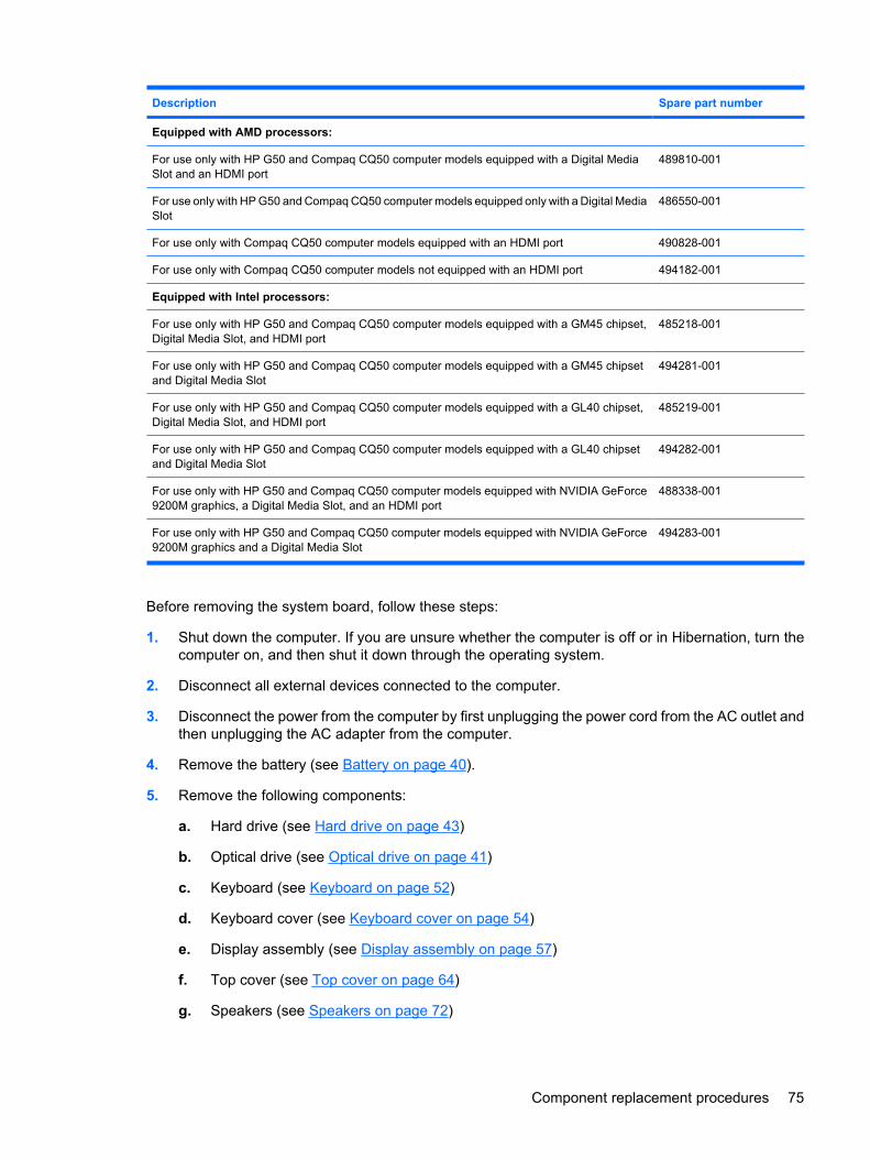
Description Spare part number
Equipped with AMD processors:
For use only with HP G50 and Compaq CQ50 computer models equipped with a Digital MediaSlot and an HDMI port
489810-001
For use only with HP G50 and Compaq CQ50 computer models equipped only with a Digital MediaSlot
486550-001
For use only with Compaq CQ50 computer models equipped with an HDMI port 490828-001
For use only with Compaq CQ50 computer models not equipped with an HDMI port 494182-001
Equipped with Intel processors:
For use only with HP G50 and Compaq CQ50 computer models equipped with a GM45 chipset,Digital Media Slot, and HDMI port
485218-001
For use only with HP G50 and Compaq CQ50 computer models equipped with a GM45 chipsetand Digital Media Slot
494281-001
For use only with HP G50 and Compaq CQ50 computer models equipped with a GL40 chipset,Digital Media Slot, and HDMI port
485219-001
For use only with HP G50 and Compaq CQ50 computer models equipped with a GL40 chipsetand Digital Media Slot
494282-001
For use only with HP G50 and Compaq CQ50 computer models equipped with NVIDIA GeForce9200M graphics, a Digital Media Slot, and an HDMI port
488338-001
For use only with HP G50 and Compaq CQ50 computer models equipped with NVIDIA GeForce9200M graphics and a Digital Media Slot
494283-001
Before removing the system board, follow these steps:
1. Shut down the computer. If you are unsure whether the computer is off or in Hibernation, turn thecomputer on, and then shut it down through the operating system.
2. Disconnect all external devices connected to the computer.
3. Disconnect the power from the computer by first unplugging the power cord from the AC outlet andthen unplugging the AC adapter from the computer.
4. Remove the battery (see Battery on page 40).
5. Remove the following components:
a. Hard drive (see Hard drive on page 43)
b. Optical drive (see Optical drive on page 41)
c. Keyboard (see Keyboard on page 52)
d. Keyboard cover (see Keyboard cover on page 54)
e. Display assembly (see Display assembly on page 57)
f. Top cover (see Top cover on page 64)
g. Speakers (see Speakers on page 72)
Component replacement procedures 75
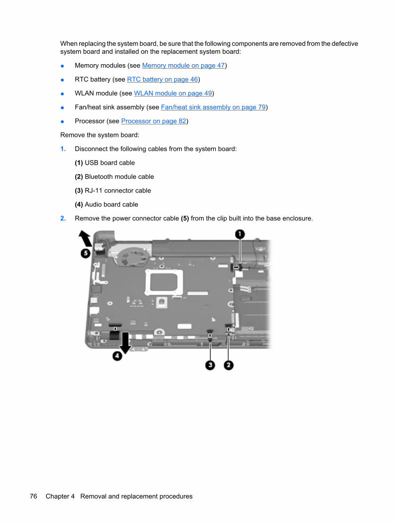
When replacing the system board, be sure that the following components are removed from the defectivesystem board and installed on the replacement system board:
● Memory modules (see Memory module on page 47)
● RTC battery (see RTC battery on page 46)
● WLAN module (see WLAN module on page 49)
● Fan/heat sink assembly (see Fan/heat sink assembly on page 79)
● Processor (see Processor on page 82)
Remove the system board:
1. Disconnect the following cables from the system board:
(1) USB board cable
(2) Bluetooth module cable
(3) RJ-11 connector cable
(4) Audio board cable
2. Remove the power connector cable (5) from the clip built into the base enclosure.
76 Chapter 4 Removal and replacement procedures
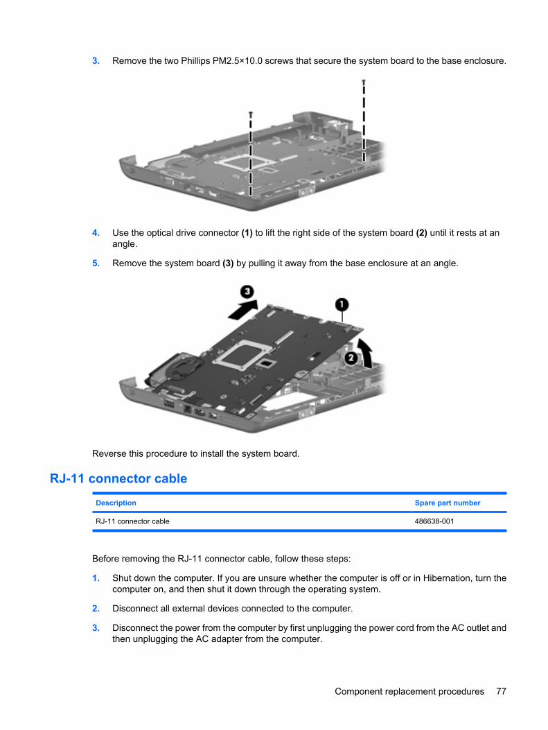
3. Remove the two Phillips PM2.5×10.0 screws that secure the system board to the base enclosure.
4. Use the optical drive connector (1) to lift the right side of the system board (2) until it rests at anangle.
5. Remove the system board (3) by pulling it away from the base enclosure at an angle.
Reverse this procedure to install the system board.
RJ-11 connector cable
Description Spare part number
RJ-11 connector cable 486638-001
Before removing the RJ-11 connector cable, follow these steps:
1. Shut down the computer. If you are unsure whether the computer is off or in Hibernation, turn thecomputer on, and then shut it down through the operating system.
2. Disconnect all external devices connected to the computer.
3. Disconnect the power from the computer by first unplugging the power cord from the AC outlet andthen unplugging the AC adapter from the computer.
Component replacement procedures 77
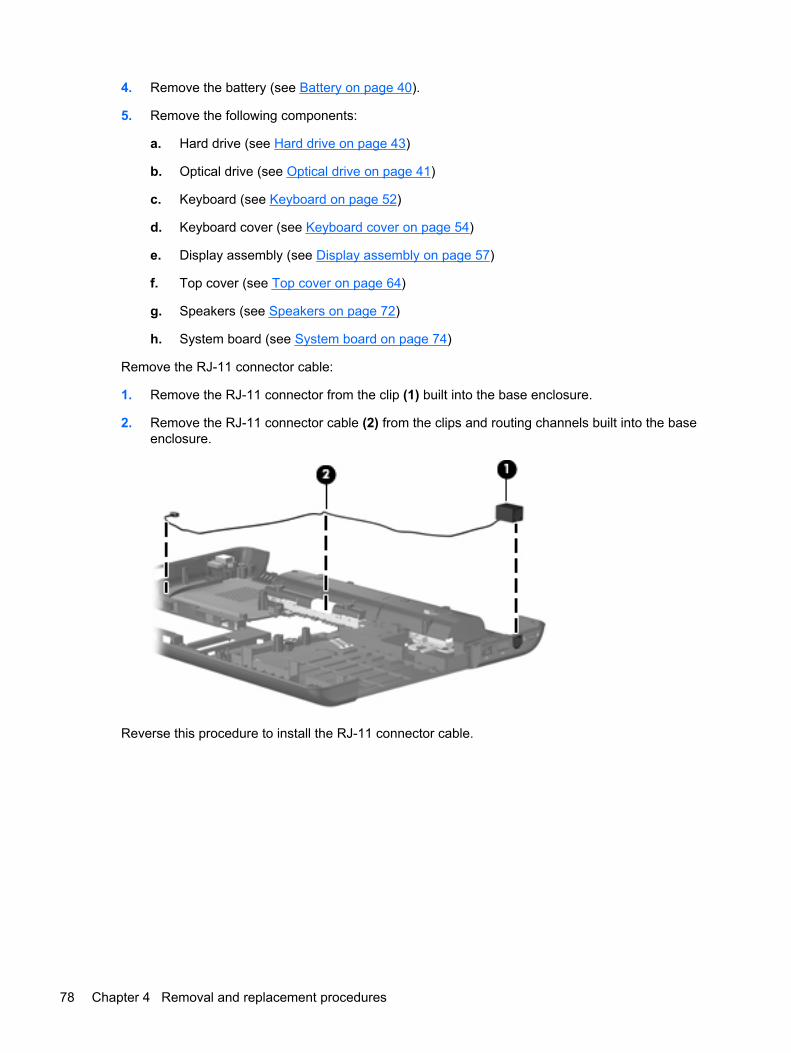
4. Remove the battery (see Battery on page 40).
5. Remove the following components:
a. Hard drive (see Hard drive on page 43)
b. Optical drive (see Optical drive on page 41)
c. Keyboard (see Keyboard on page 52)
d. Keyboard cover (see Keyboard cover on page 54)
e. Display assembly (see Display assembly on page 57)
f. Top cover (see Top cover on page 64)
g. Speakers (see Speakers on page 72)
h. System board (see System board on page 74)
Remove the RJ-11 connector cable:
1. Remove the RJ-11 connector from the clip (1) built into the base enclosure.
2. Remove the RJ-11 connector cable (2) from the clips and routing channels built into the baseenclosure.
Reverse this procedure to install the RJ-11 connector cable.
78 Chapter 4 Removal and replacement procedures
Fan/heat sink assembly
Description Spare part number
Fan/heat sink assembly (includes replacement thermal material) 486636-001
Before removing the fan/heat sink assembly, follow these steps:
1. Shut down the computer. If you are unsure whether the computer is off or in Hibernation, turn thecomputer on, and then shut it down through the operating system.
2. Disconnect all external devices connected to the computer.
3. Disconnect the power from the computer by first unplugging the power cord from the AC outlet andthen unplugging the AC adapter from the computer.
4. Remove the battery (see Battery on page 40).
5. Remove the following components:
a. Hard drive (see Hard drive on page 43)
b. Optical drive (see Optical drive on page 41)
c. Keyboard (see Keyboard on page 52)
d. Keyboard cover (see Keyboard cover on page 54)
e. Display assembly (see Display assembly on page 57)
f. Top cover (see Top cover on page 64)
g. Speakers (see Speakers on page 72)
h. System board (see System board on page 74)
Component replacement procedures 79
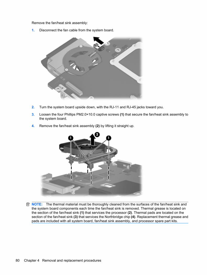
Remove the fan/heat sink assembly:
1. Disconnect the fan cable from the system board.
2. Turn the system board upside down, with the RJ-11 and RJ-45 jacks toward you.
3. Loosen the four Phillips PM2.0×10.0 captive screws (1) that secure the fan/heat sink assembly tothe system board.
4. Remove the fan/heat sink assembly (2) by lifting it straight up.
NOTE: The thermal material must be thoroughly cleaned from the surfaces of the fan/heat sink andthe system board components each time the fan/heat sink is removed. Thermal grease is located onthe section of the fan/heat sink (1) that services the processor (2). Thermal pads are located on thesection of the fan/heat sink (3) that services the Northbridge chip (4). Replacement thermal grease andpads are included with all system board, fan/heat sink assembly, and processor spare part kits.
80 Chapter 4 Removal and replacement procedures
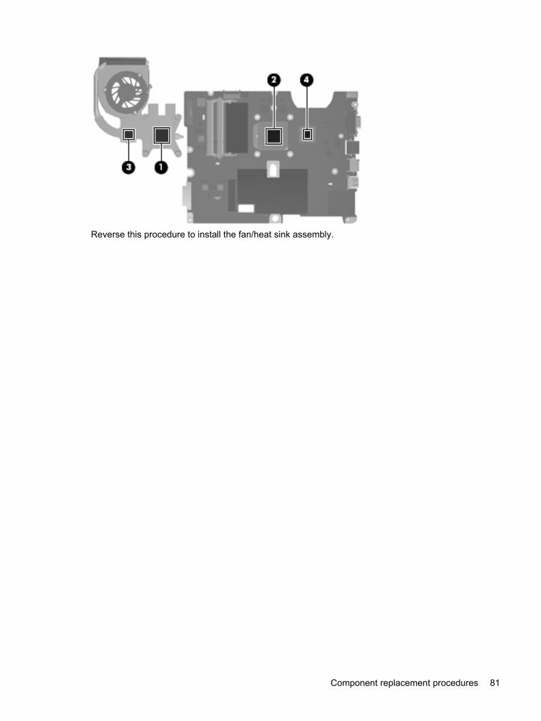
Reverse this procedure to install the fan/heat sink assembly.
Component replacement procedures 81
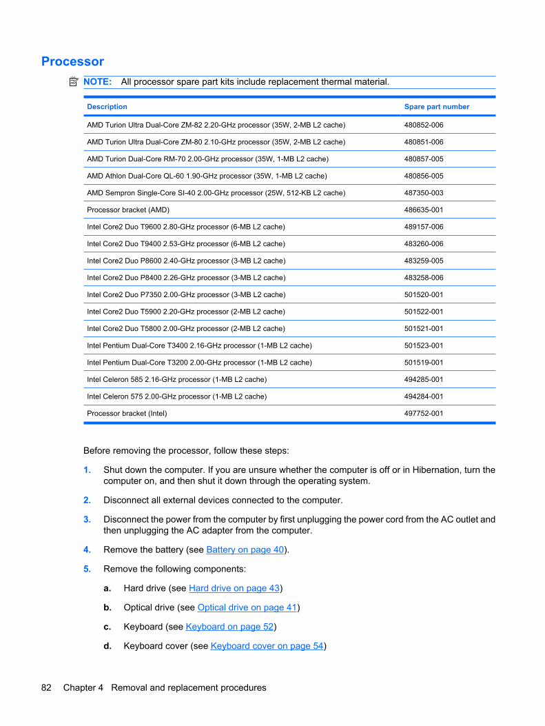
ProcessorNOTE: All processor spare part kits include replacement thermal material.
Description Spare part number
AMD Turion Ultra Dual-Core ZM-82 2.20-GHz processor (35W, 2-MB L2 cache) 480852-006
AMD Turion Ultra Dual-Core ZM-80 2.10-GHz processor (35W, 2-MB L2 cache) 480851-006
AMD Turion Dual-Core RM-70 2.00-GHz processor (35W, 1-MB L2 cache) 480857-005
AMD Athlon Dual-Core QL-60 1.90-GHz processor (35W, 1-MB L2 cache) 480856-005
AMD Sempron Single-Core SI-40 2.00-GHz processor (25W, 512-KB L2 cache) 487350-003
Processor bracket (AMD) 486635-001
Intel Core2 Duo T9600 2.80-GHz processor (6-MB L2 cache) 489157-006
Intel Core2 Duo T9400 2.53-GHz processor (6-MB L2 cache) 483260-006
Intel Core2 Duo P8600 2.40-GHz processor (3-MB L2 cache) 483259-005
Intel Core2 Duo P8400 2.26-GHz processor (3-MB L2 cache) 483258-006
Intel Core2 Duo P7350 2.00-GHz processor (3-MB L2 cache) 501520-001
Intel Core2 Duo T5900 2.20-GHz processor (2-MB L2 cache) 501522-001
Intel Core2 Duo T5800 2.00-GHz processor (2-MB L2 cache) 501521-001
Intel Pentium Dual-Core T3400 2.16-GHz processor (1-MB L2 cache) 501523-001
Intel Pentium Dual-Core T3200 2.00-GHz processor (1-MB L2 cache) 501519-001
Intel Celeron 585 2.16-GHz processor (1-MB L2 cache) 494285-001
Intel Celeron 575 2.00-GHz processor (1-MB L2 cache) 494284-001
Processor bracket (Intel) 497752-001
Before removing the processor, follow these steps:
1. Shut down the computer. If you are unsure whether the computer is off or in Hibernation, turn thecomputer on, and then shut it down through the operating system.
2. Disconnect all external devices connected to the computer.
3. Disconnect the power from the computer by first unplugging the power cord from the AC outlet andthen unplugging the AC adapter from the computer.
4. Remove the battery (see Battery on page 40).
5. Remove the following components:
a. Hard drive (see Hard drive on page 43)
b. Optical drive (see Optical drive on page 41)
c. Keyboard (see Keyboard on page 52)
d. Keyboard cover (see Keyboard cover on page 54)
82 Chapter 4 Removal and replacement procedures
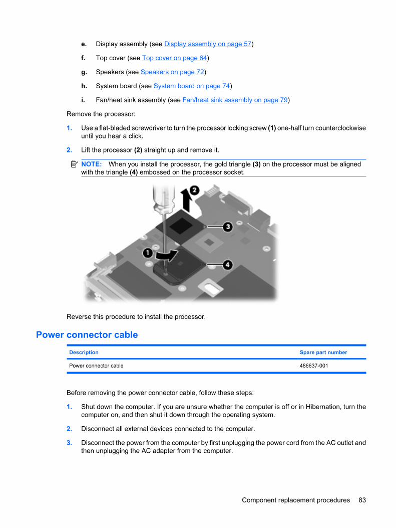
e. Display assembly (see Display assembly on page 57)
f. Top cover (see Top cover on page 64)
g. Speakers (see Speakers on page 72)
h. System board (see System board on page 74)
i. Fan/heat sink assembly (see Fan/heat sink assembly on page 79)
Remove the processor:
1. Use a flat-bladed screwdriver to turn the processor locking screw (1) one-half turn counterclockwiseuntil you hear a click.
2. Lift the processor (2) straight up and remove it.
NOTE: When you install the processor, the gold triangle (3) on the processor must be alignedwith the triangle (4) embossed on the processor socket.
Reverse this procedure to install the processor.
Power connector cable
Description Spare part number
Power connector cable 486637-001
Before removing the power connector cable, follow these steps:
1. Shut down the computer. If you are unsure whether the computer is off or in Hibernation, turn thecomputer on, and then shut it down through the operating system.
2. Disconnect all external devices connected to the computer.
3. Disconnect the power from the computer by first unplugging the power cord from the AC outlet andthen unplugging the AC adapter from the computer.
Component replacement procedures 83
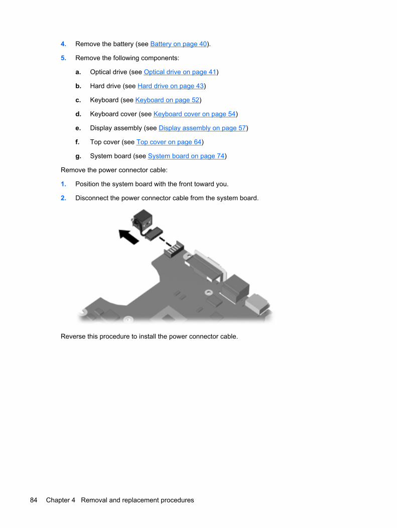
4. Remove the battery (see Battery on page 40).
5. Remove the following components:
a. Optical drive (see Optical drive on page 41)
b. Hard drive (see Hard drive on page 43)
c. Keyboard (see Keyboard on page 52)
d. Keyboard cover (see Keyboard cover on page 54)
e. Display assembly (see Display assembly on page 57)
f. Top cover (see Top cover on page 64)
g. System board (see System board on page 74)
Remove the power connector cable:
1. Position the system board with the front toward you.
2. Disconnect the power connector cable from the system board.
Reverse this procedure to install the power connector cable.
84 Chapter 4 Removal and replacement procedures

5 Setup Utility
WARNING! Only authorized technicians trained by HP must repair this equipment. All troubleshootingand repair procedures are detailed to allow repair at only the subassembly or module level. Because ofthe complexity of the individual boards and subassemblies, do not attempt to make repairs at thecomponent level or modify any printed wiring board. Improper repairs can create a safety hazard. Anyindication of component replacement or printed wiring board modification may void any warranty orexchange allowances.
Starting the Setup UtilityThe Setup Utility is a ROM-based information and customization utility that can be used even when yourWindows® operating system is not working.
NOTE: The fingerprint reader (select models only) cannot be used to access the Setup Utility.
The utility reports information about the computer and provides settings for startup, security, and otherpreferences.
To start the Setup Utility:
� Open the Setup Utility by turning on or restarting the computer. While the “Press the ESC key forStartup Menu” message is displayed in the lower-left corner of the screen, press f10.
– or –
1. Open the Setup Utility by turning on or restarting the computer. While the “Press the ESC key forStartup Menu” message is displayed in the lower-left corner of the screen, press esc.
2. When the Startup Menu is displayed, press f10.
Changing the language of the Setup UtilityThe following procedure explains how to change the language of the Setup Utility. If the Setup Utility isnot already running, begin at step 1. If the Setup Utility is already running, begin at step 2.
1. Open the Setup Utility by turning on or restarting the computer. While the “Press the ESC key forStartup Menu” message is displayed in the lower-left corner of the screen, press f10.
– or –
Open the Setup Utility by turning on or restarting the computer. While the “Press the ESC key forStartup Menu” message is displayed in the lower-left corner of the screen, press esc. When theStartup Menu is displayed, press f10.
2. Use the arrow keys to select System Configuration > Language, and then press enter.
Starting the Setup Utility 85
3. Use the arrow keys to select a language, and then press enter.
4. When a confirmation prompt with your language selected is displayed, press enter.
5. To save your change and exit the Setup Utility, use the arrow keys to select Exit > Exit SavingChanges, and then press enter.
Your change goes into effect immediately.
Navigating and selecting in the Setup UtilityBecause the Setup Utility is not Windows based, it does not support the TouchPad. Navigation andselection are by keystroke.
● To choose a menu or a menu item, use the arrow keys.
● To choose an item in a list or to toggle a field, for example an Enable/Disable field, use either thearrow keys or f5 or f6.
● To select an item, press enter.
● To close a text box or return to the menu display, press esc.
● To display additional navigation and selection information while the Setup Utility is open, pressf1.
Displaying system informationThe following procedure explains how to display system information in the Setup Utility. If the SetupUtility is not open, begin at step 1. If the Setup Utility is open, begin at step 2.
1. Open the Setup Utility by turning on or restarting the computer. While the “Press the ESC key forStartup Menu” message is displayed in the lower-left corner of the screen, press f10.
– or –
Open the Setup Utility by turning on or restarting the computer. While the “Press the ESC key forStartup Menu” message is displayed in the lower-left corner of the screen, press esc. When theStartup Menu is displayed, press f10.
2. Select the Main menu. System information such as the system time and date, and identificationinformation about the computer is displayed.
3. To exit the Setup Utility without changing any settings, use the arrow keys to select Exit > ExitDiscarding Changes, and then press enter.
86 Chapter 5 Setup Utility
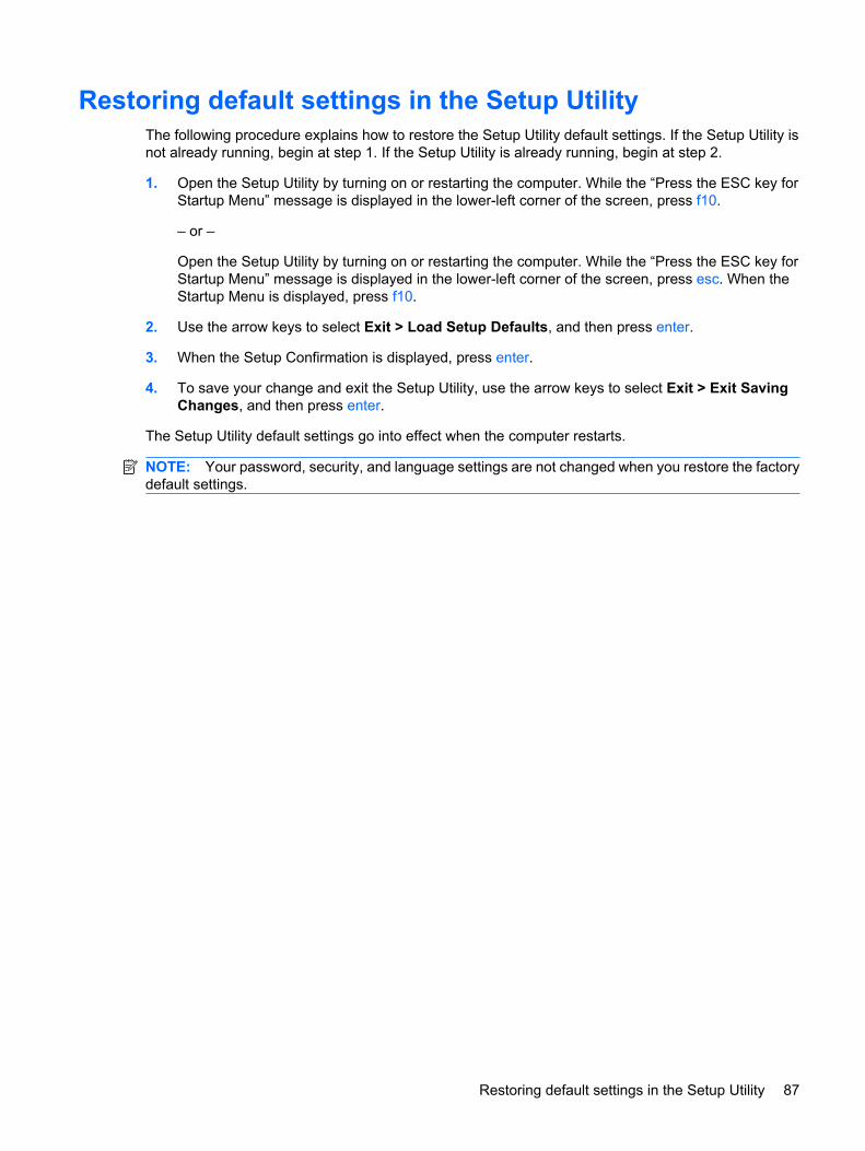
Restoring default settings in the Setup UtilityThe following procedure explains how to restore the Setup Utility default settings. If the Setup Utility isnot already running, begin at step 1. If the Setup Utility is already running, begin at step 2.
1. Open the Setup Utility by turning on or restarting the computer. While the “Press the ESC key forStartup Menu” message is displayed in the lower-left corner of the screen, press f10.
– or –
Open the Setup Utility by turning on or restarting the computer. While the “Press the ESC key forStartup Menu” message is displayed in the lower-left corner of the screen, press esc. When theStartup Menu is displayed, press f10.
2. Use the arrow keys to select Exit > Load Setup Defaults, and then press enter.
3. When the Setup Confirmation is displayed, press enter.
4. To save your change and exit the Setup Utility, use the arrow keys to select Exit > Exit SavingChanges, and then press enter.
The Setup Utility default settings go into effect when the computer restarts.
NOTE: Your password, security, and language settings are not changed when you restore the factorydefault settings.
Restoring default settings in the Setup Utility 87
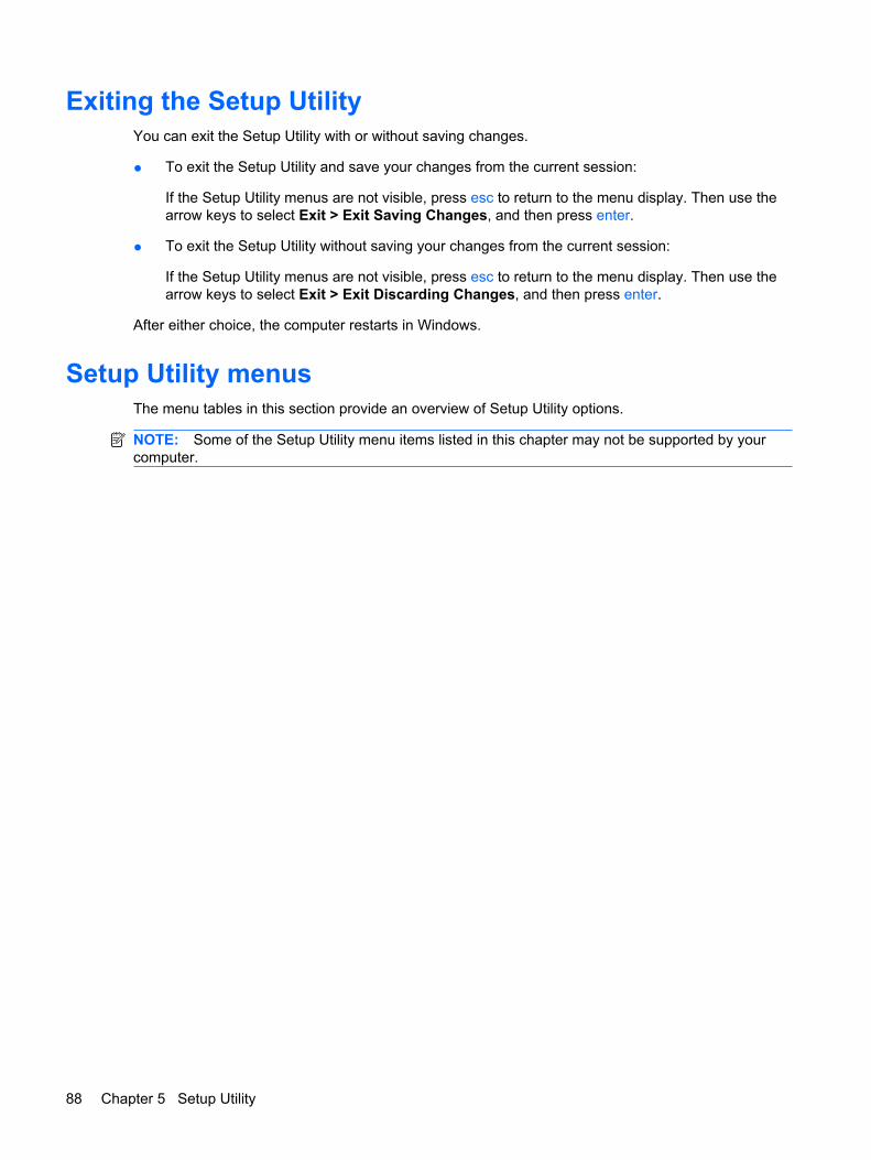
Exiting the Setup UtilityYou can exit the Setup Utility with or without saving changes.
● To exit the Setup Utility and save your changes from the current session:
If the Setup Utility menus are not visible, press esc to return to the menu display. Then use thearrow keys to select Exit > Exit Saving Changes, and then press enter.
● To exit the Setup Utility without saving your changes from the current session:
If the Setup Utility menus are not visible, press esc to return to the menu display. Then use thearrow keys to select Exit > Exit Discarding Changes, and then press enter.
After either choice, the computer restarts in Windows.
Setup Utility menusThe menu tables in this section provide an overview of Setup Utility options.
NOTE: Some of the Setup Utility menu items listed in this chapter may not be supported by yourcomputer.
88 Chapter 5 Setup Utility
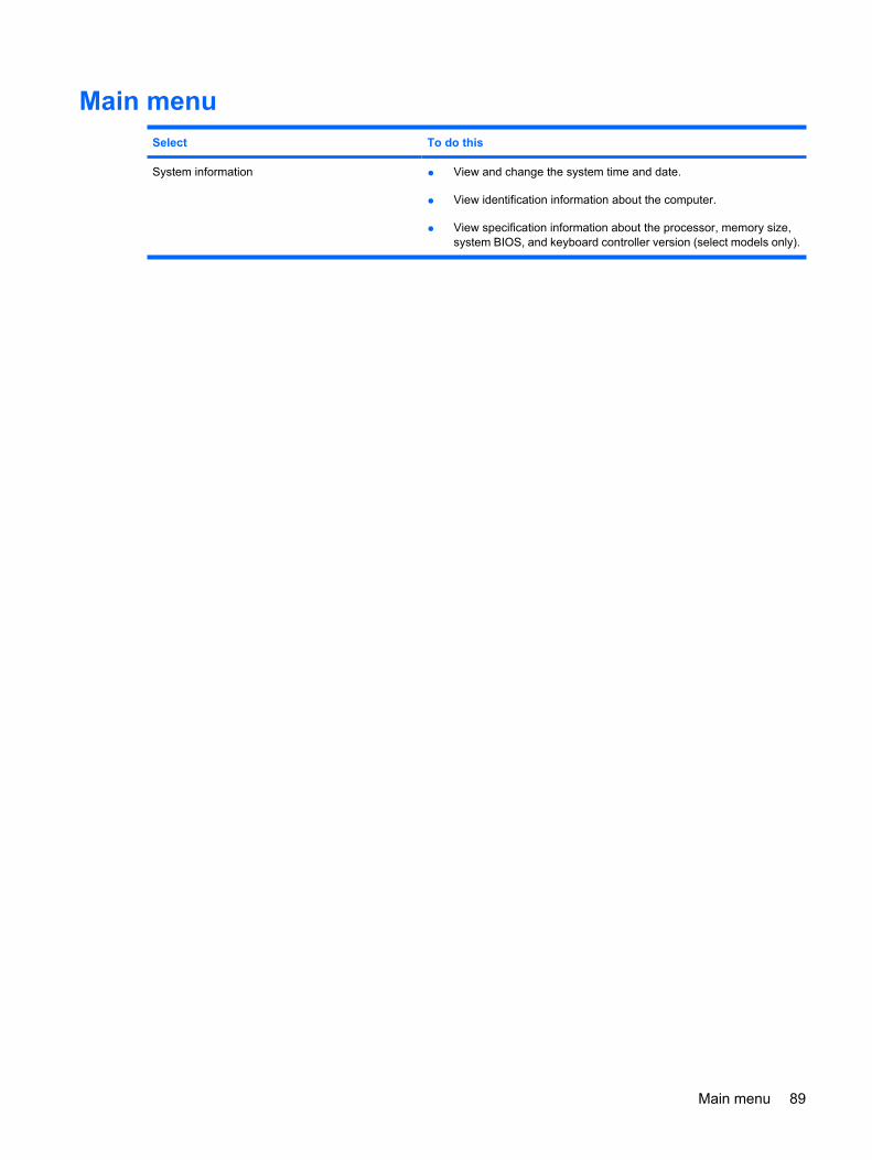
Main menuSelect To do this
System information ● View and change the system time and date.
● View identification information about the computer.
● View specification information about the processor, memory size,system BIOS, and keyboard controller version (select models only).
Main menu 89
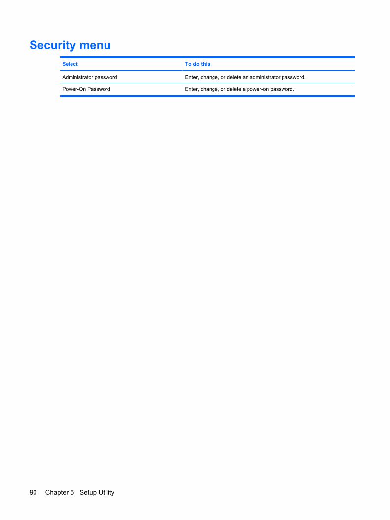
Security menuSelect To do this
Administrator password Enter, change, or delete an administrator password.
Power-On Password Enter, change, or delete a power-on password.
90 Chapter 5 Setup Utility
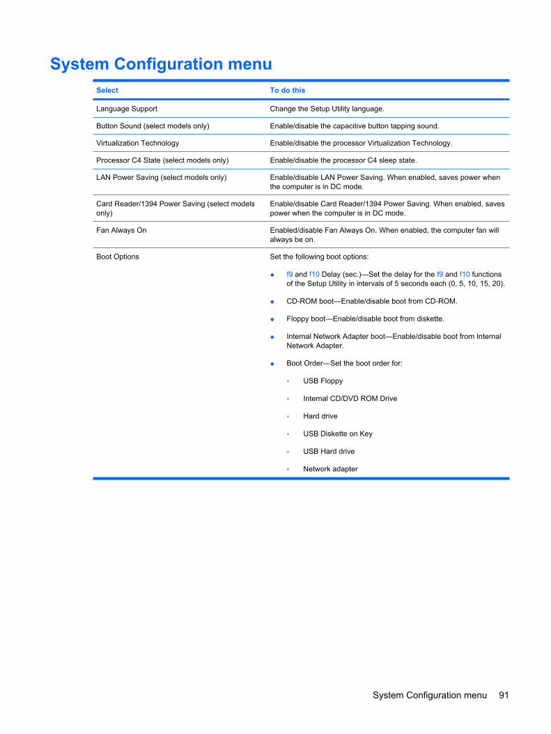
System Configuration menuSelect To do this
Language Support Change the Setup Utility language.
Button Sound (select models only) Enable/disable the capacitive button tapping sound.
Virtualization Technology Enable/disable the processor Virtualization Technology.
Processor C4 State (select models only) Enable/disable the processor C4 sleep state.
LAN Power Saving (select models only) Enable/disable LAN Power Saving. When enabled, saves power whenthe computer is in DC mode.
Card Reader/1394 Power Saving (select modelsonly)
Enable/disable Card Reader/1394 Power Saving. When enabled, savespower when the computer is in DC mode.
Fan Always On Enabled/disable Fan Always On. When enabled, the computer fan willalways be on.
Boot Options Set the following boot options:
● f9 and f10 Delay (sec.)―Set the delay for the f9 and f10 functionsof the Setup Utility in intervals of 5 seconds each (0, 5, 10, 15, 20).
● CD-ROM boot―Enable/disable boot from CD-ROM.
● Floppy boot―Enable/disable boot from diskette.
● Internal Network Adapter boot―Enable/disable boot from InternalNetwork Adapter.
● Boot Order―Set the boot order for:
◦ USB Floppy
◦ Internal CD/DVD ROM Drive
◦ Hard drive
◦ USB Diskette on Key
◦ USB Hard drive
◦ Network adapter
System Configuration menu 91
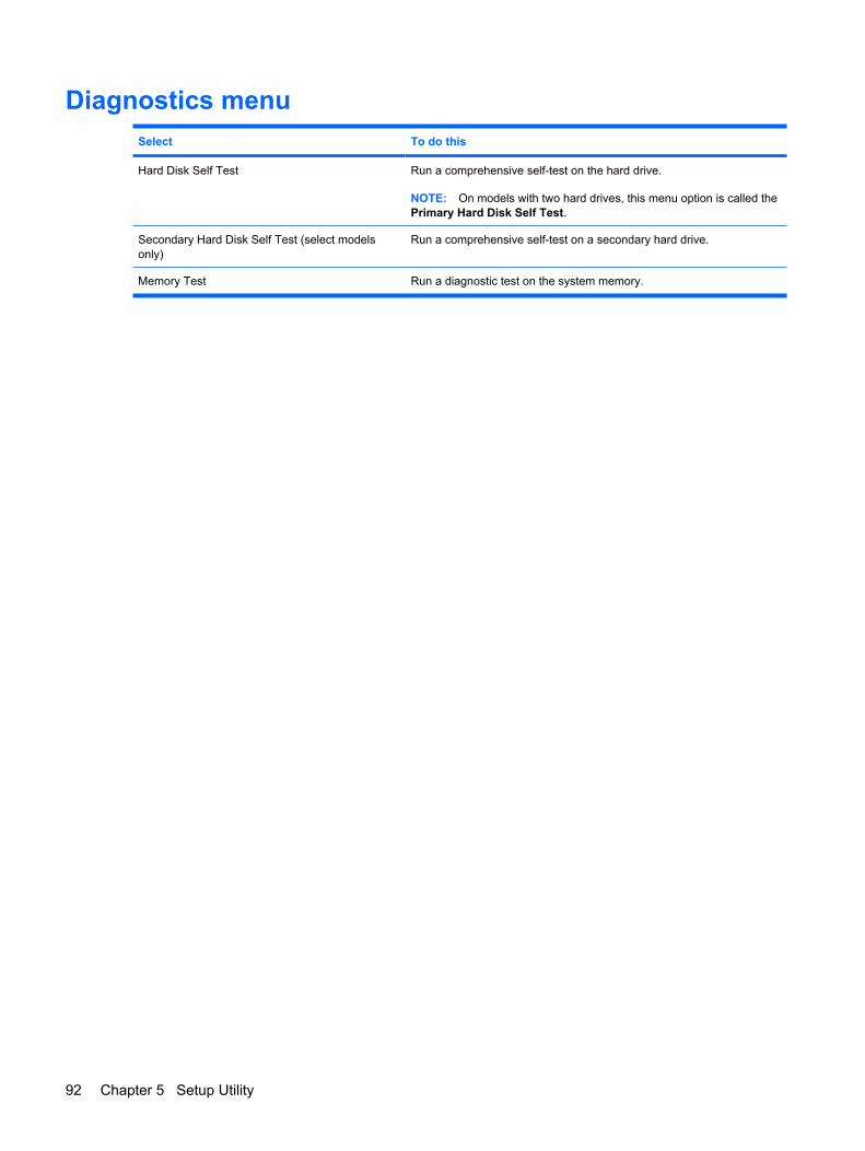
Diagnostics menuSelect To do this
Hard Disk Self Test Run a comprehensive self-test on the hard drive.
NOTE: On models with two hard drives, this menu option is called thePrimary Hard Disk Self Test.
Secondary Hard Disk Self Test (select modelsonly)
Run a comprehensive self-test on a secondary hard drive.
Memory Test Run a diagnostic test on the system memory.
92 Chapter 5 Setup Utility
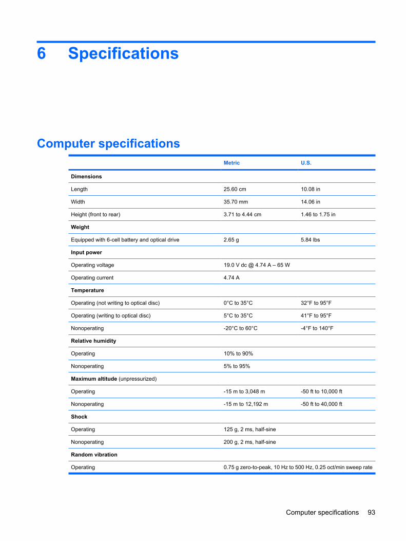
6 Specifications
Computer specifications Metric U.S.
Dimensions
Length 25.60 cm 10.08 in
Width 35.70 mm 14.06 in
Height (front to rear) 3.71 to 4.44 cm 1.46 to 1.75 in
Weight
Equipped with 6-cell battery and optical drive 2.65 g 5.84 lbs
Input power
Operating voltage 19.0 V dc @ 4.74 A – 65 W
Operating current 4.74 A
Temperature
Operating (not writing to optical disc) 0°C to 35°C 32°F to 95°F
Operating (writing to optical disc) 5°C to 35°C 41°F to 95°F
Nonoperating -20°C to 60°C -4°F to 140°F
Relative humidity
Operating 10% to 90%
Nonoperating 5% to 95%
Maximum altitude (unpressurized)
Operating -15 m to 3,048 m -50 ft to 10,000 ft
Nonoperating -15 m to 12,192 m -50 ft to 40,000 ft
Shock
Operating 125 g, 2 ms, half-sine
Nonoperating 200 g, 2 ms, half-sine
Random vibration
Operating 0.75 g zero-to-peak, 10 Hz to 500 Hz, 0.25 oct/min sweep rate
Computer specifications 93
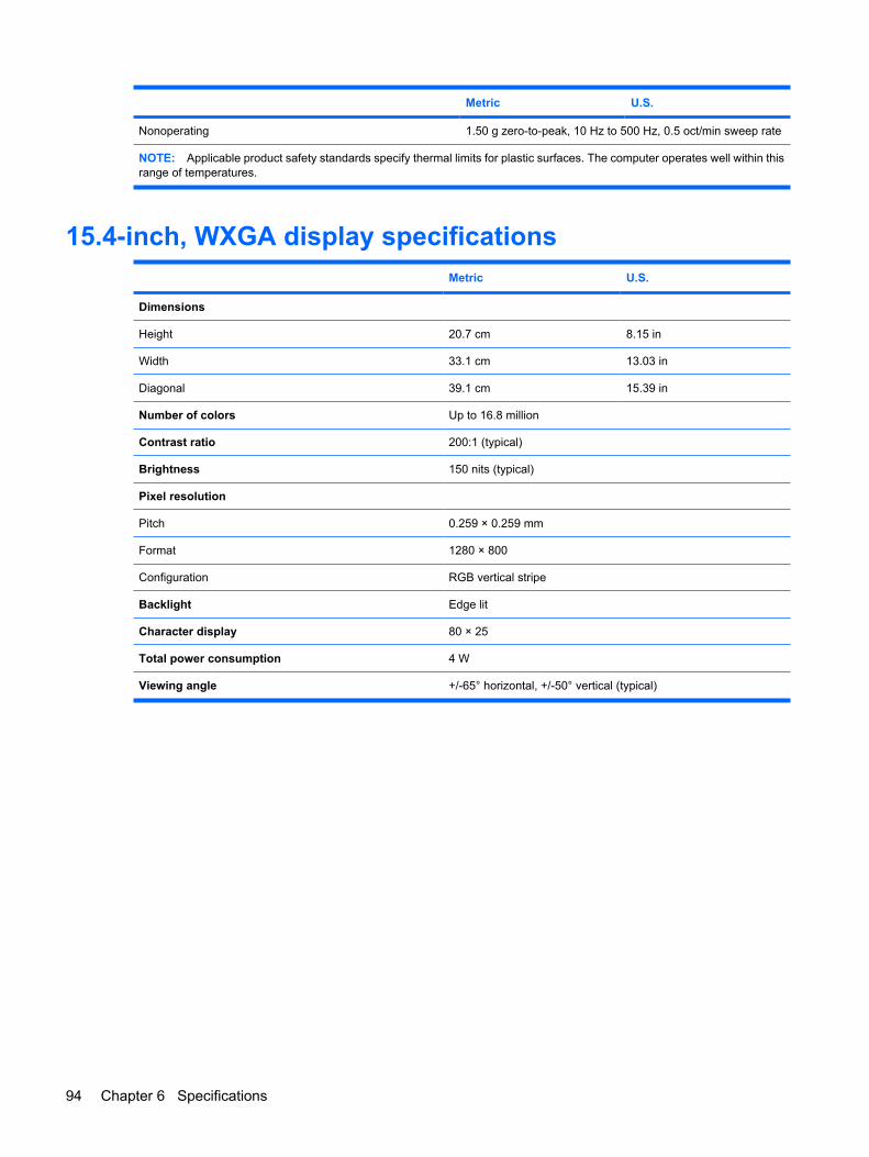
Metric U.S.
Nonoperating 1.50 g zero-to-peak, 10 Hz to 500 Hz, 0.5 oct/min sweep rate
NOTE: Applicable product safety standards specify thermal limits for plastic surfaces. The computer operates well within thisrange of temperatures.
15.4-inch, WXGA display specifications Metric U.S.
Dimensions
Height 20.7 cm 8.15 in
Width 33.1 cm 13.03 in
Diagonal 39.1 cm 15.39 in
Number of colors Up to 16.8 million
Contrast ratio 200:1 (typical)
Brightness 150 nits (typical)
Pixel resolution
Pitch 0.259 × 0.259 mm
Format 1280 × 800
Configuration RGB vertical stripe
Backlight Edge lit
Character display 80 × 25
Total power consumption 4 W
Viewing angle +/-65° horizontal, +/-50° vertical (typical)
94 Chapter 6 Specifications
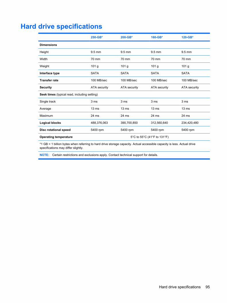
Hard drive specifications 250-GB* 200-GB* 160-GB* 120-GB*
Dimensions
Height 9.5 mm 9.5 mm 9.5 mm 9.5 mm
Width 70 mm 70 mm 70 mm 70 mm
Weight 101 g 101 g 101 g 101 g
Interface type SATA SATA SATA SATA
Transfer rate 100 MB/sec 100 MB/sec 100 MB/sec 100 MB/sec
Security ATA security ATA security ATA security ATA security
Seek times (typical read, including setting)
Single track 3 ms 3 ms 3 ms 3 ms
Average 13 ms 13 ms 13 ms 13 ms
Maximum 24 ms 24 ms 24 ms 24 ms
Logical blocks 488,376,063 390,700,850 312,560,640 234,420,480
Disc rotational speed 5400 rpm 5400 rpm 5400 rpm 5400 rpm
Operating temperature 5°C to 55°C (41°F to 131°F)
*1 GB = 1 billion bytes when referring to hard drive storage capacity. Actual accessible capacity is less. Actual drivespecifications may differ slightly.
NOTE: Certain restrictions and exclusions apply. Contact technical support for details.
Hard drive specifications 95
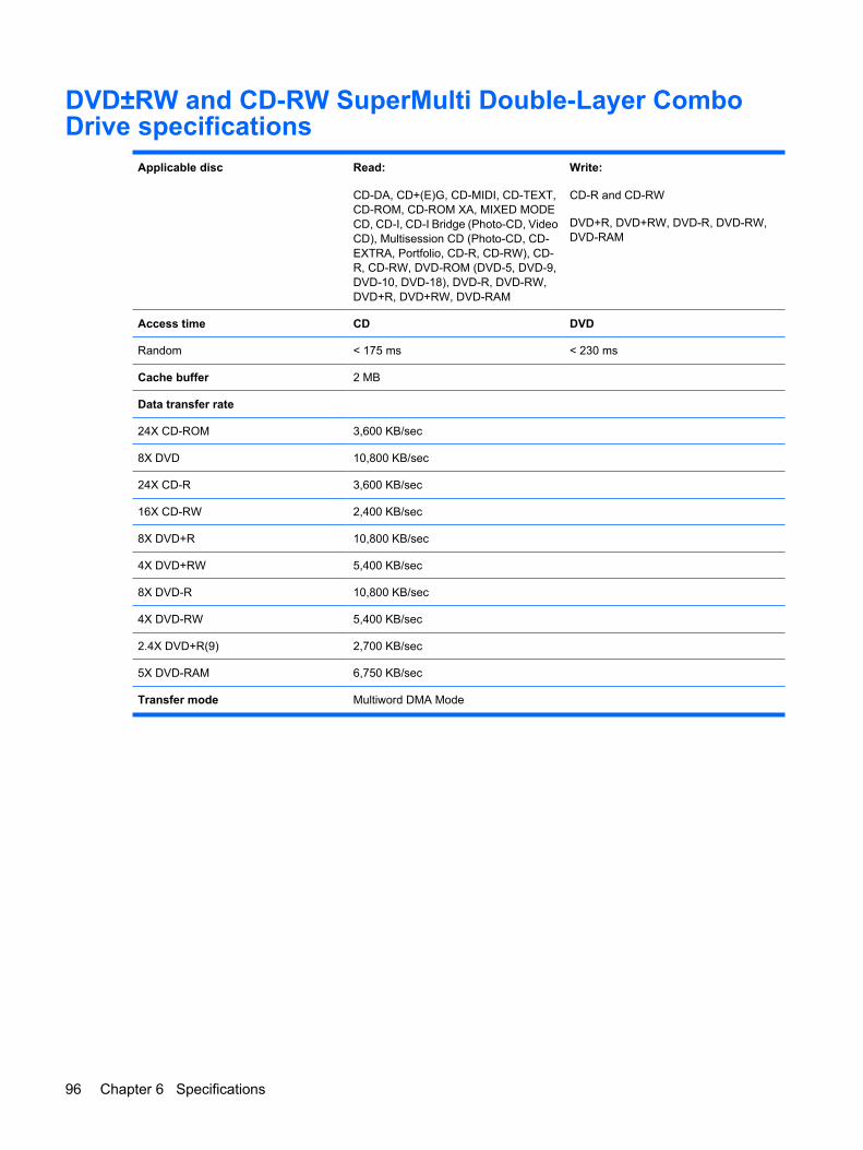
DVD±RW and CD-RW SuperMulti Double-Layer ComboDrive specifications
Applicable disc Read:
CD-DA, CD+(E)G, CD-MIDI, CD-TEXT,CD-ROM, CD-ROM XA, MIXED MODECD, CD-I, CD-I Bridge (Photo-CD, VideoCD), Multisession CD (Photo-CD, CD-EXTRA, Portfolio, CD-R, CD-RW), CD-R, CD-RW, DVD-ROM (DVD-5, DVD-9,DVD-10, DVD-18), DVD-R, DVD-RW,DVD+R, DVD+RW, DVD-RAM
Write:
CD-R and CD-RW
DVD+R, DVD+RW, DVD-R, DVD-RW,DVD-RAM
Access time CD DVD
Random < 175 ms < 230 ms
Cache buffer 2 MB
Data transfer rate
24X CD-ROM 3,600 KB/sec
8X DVD 10,800 KB/sec
24X CD-R 3,600 KB/sec
16X CD-RW 2,400 KB/sec
8X DVD+R 10,800 KB/sec
4X DVD+RW 5,400 KB/sec
8X DVD-R 10,800 KB/sec
4X DVD-RW 5,400 KB/sec
2.4X DVD+R(9) 2,700 KB/sec
5X DVD-RAM 6,750 KB/sec
Transfer mode Multiword DMA Mode
96 Chapter 6 Specifications
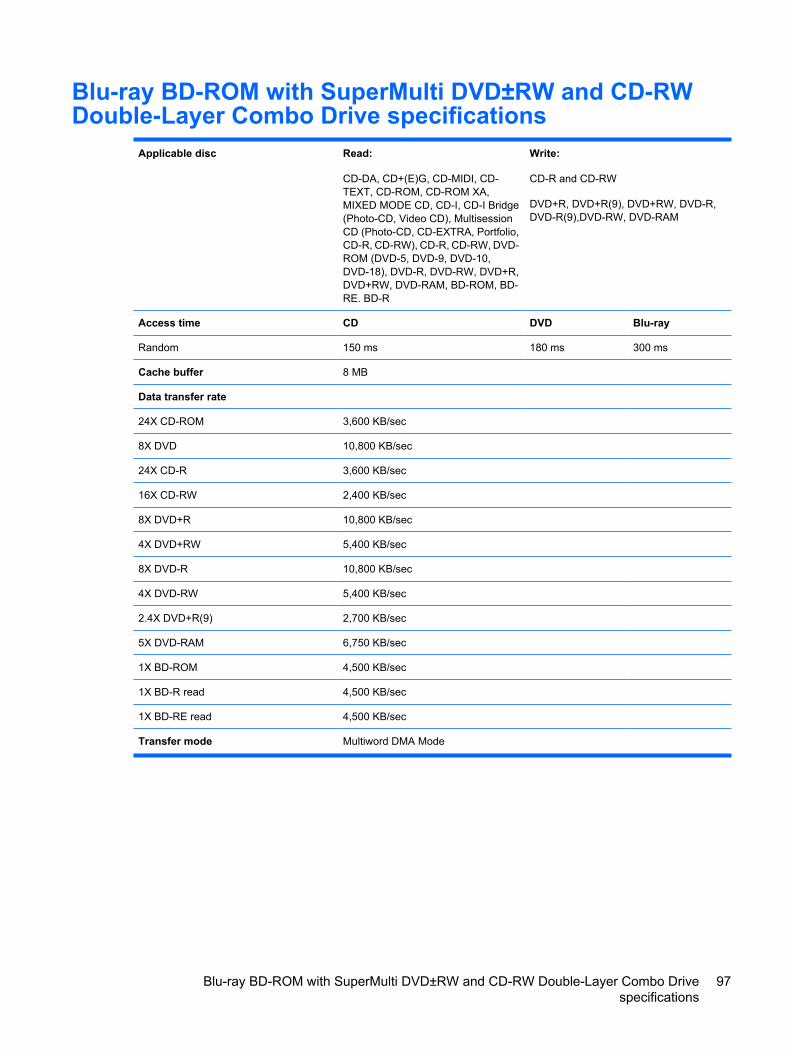
Blu-ray BD-ROM with SuperMulti DVD±RW and CD-RWDouble-Layer Combo Drive specifications
Applicable disc Read:
CD-DA, CD+(E)G, CD-MIDI, CD-TEXT, CD-ROM, CD-ROM XA,MIXED MODE CD, CD-I, CD-I Bridge(Photo-CD, Video CD), MultisessionCD (Photo-CD, CD-EXTRA, Portfolio,CD-R, CD-RW), CD-R, CD-RW, DVD-ROM (DVD-5, DVD-9, DVD-10,DVD-18), DVD-R, DVD-RW, DVD+R,DVD+RW, DVD-RAM, BD-ROM, BD-RE. BD-R
Write:
CD-R and CD-RW
DVD+R, DVD+R(9), DVD+RW, DVD-R,DVD-R(9),DVD-RW, DVD-RAM
Access time CD DVD Blu-ray
Random 150 ms 180 ms 300 ms
Cache buffer 8 MB
Data transfer rate
24X CD-ROM 3,600 KB/sec
8X DVD 10,800 KB/sec
24X CD-R 3,600 KB/sec
16X CD-RW 2,400 KB/sec
8X DVD+R 10,800 KB/sec
4X DVD+RW 5,400 KB/sec
8X DVD-R 10,800 KB/sec
4X DVD-RW 5,400 KB/sec
2.4X DVD+R(9) 2,700 KB/sec
5X DVD-RAM 6,750 KB/sec
1X BD-ROM 4,500 KB/sec
1X BD-R read 4,500 KB/sec
1X BD-RE read 4,500 KB/sec
Transfer mode Multiword DMA Mode
Blu-ray BD-ROM with SuperMulti DVD±RW and CD-RW Double-Layer Combo Drivespecifications
97
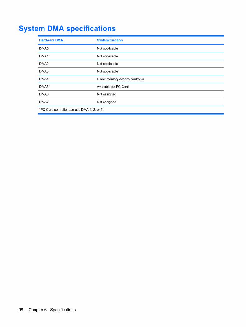
System DMA specificationsHardware DMA System function
DMA0 Not applicable
DMA1* Not applicable
DMA2* Not applicable
DMA3 Not applicable
DMA4 Direct memory access controller
DMA5* Available for PC Card
DMA6 Not assigned
DMA7 Not assigned
*PC Card controller can use DMA 1, 2, or 5.
98 Chapter 6 Specifications
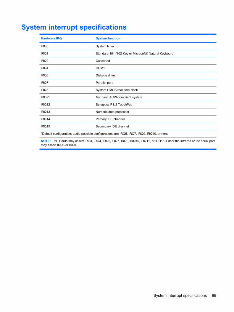
System interrupt specificationsHardware IRQ System function
IRQ0 System timer
IRQ1 Standard 101-/102-Key or Microsoft® Natural Keyboard
IRQ2 Cascaded
IRQ4 COM1
IRQ6 Diskette drive
IRQ7* Parallel port
IRQ8 System CMOS/real-time clock
IRQ9* Microsoft ACPI-compliant system
IRQ12 Synaptics PS/2 TouchPad
IRQ13 Numeric data processor
IRQ14 Primary IDE channel
IRQ15 Secondary IDE channel
*Default configuration; audio possible configurations are IRQ5, IRQ7, IRQ9, IRQ10, or none.
NOTE: PC Cards may assert IRQ3, IRQ4, IRQ5, IRQ7, IRQ9, IRQ10, IRQ11, or IRQ15. Either the infrared or the serial portmay assert IRQ3 or IRQ4.
System interrupt specifications 99
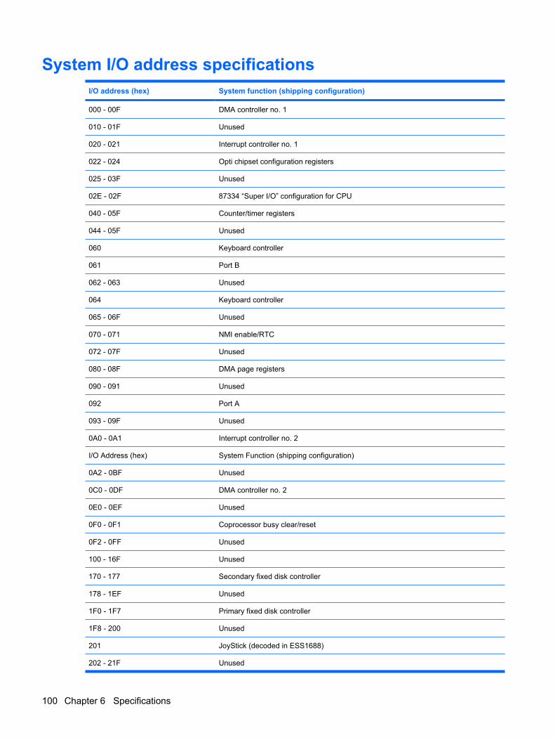
System I/O address specificationsI/O address (hex) System function (shipping configuration)
000 - 00F DMA controller no. 1
010 - 01F Unused
020 - 021 Interrupt controller no. 1
022 - 024 Opti chipset configuration registers
025 - 03F Unused
02E - 02F 87334 “Super I/O” configuration for CPU
040 - 05F Counter/timer registers
044 - 05F Unused
060 Keyboard controller
061 Port B
062 - 063 Unused
064 Keyboard controller
065 - 06F Unused
070 - 071 NMI enable/RTC
072 - 07F Unused
080 - 08F DMA page registers
090 - 091 Unused
092 Port A
093 - 09F Unused
0A0 - 0A1 Interrupt controller no. 2
I/O Address (hex) System Function (shipping configuration)
0A2 - 0BF Unused
0C0 - 0DF DMA controller no. 2
0E0 - 0EF Unused
0F0 - 0F1 Coprocessor busy clear/reset
0F2 - 0FF Unused
100 - 16F Unused
170 - 177 Secondary fixed disk controller
178 - 1EF Unused
1F0 - 1F7 Primary fixed disk controller
1F8 - 200 Unused
201 JoyStick (decoded in ESS1688)
202 - 21F Unused
100 Chapter 6 Specifications
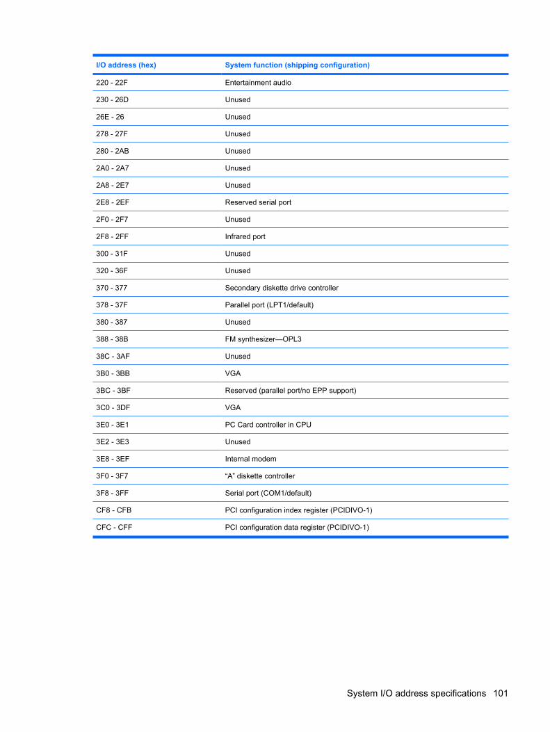
I/O address (hex) System function (shipping configuration)
220 - 22F Entertainment audio
230 - 26D Unused
26E - 26 Unused
278 - 27F Unused
280 - 2AB Unused
2A0 - 2A7 Unused
2A8 - 2E7 Unused
2E8 - 2EF Reserved serial port
2F0 - 2F7 Unused
2F8 - 2FF Infrared port
300 - 31F Unused
320 - 36F Unused
370 - 377 Secondary diskette drive controller
378 - 37F Parallel port (LPT1/default)
380 - 387 Unused
388 - 38B FM synthesizer—OPL3
38C - 3AF Unused
3B0 - 3BB VGA
3BC - 3BF Reserved (parallel port/no EPP support)
3C0 - 3DF VGA
3E0 - 3E1 PC Card controller in CPU
3E2 - 3E3 Unused
3E8 - 3EF Internal modem
3F0 - 3F7 “A” diskette controller
3F8 - 3FF Serial port (COM1/default)
CF8 - CFB PCI configuration index register (PCIDIVO-1)
CFC - CFF PCI configuration data register (PCIDIVO-1)
System I/O address specifications 101
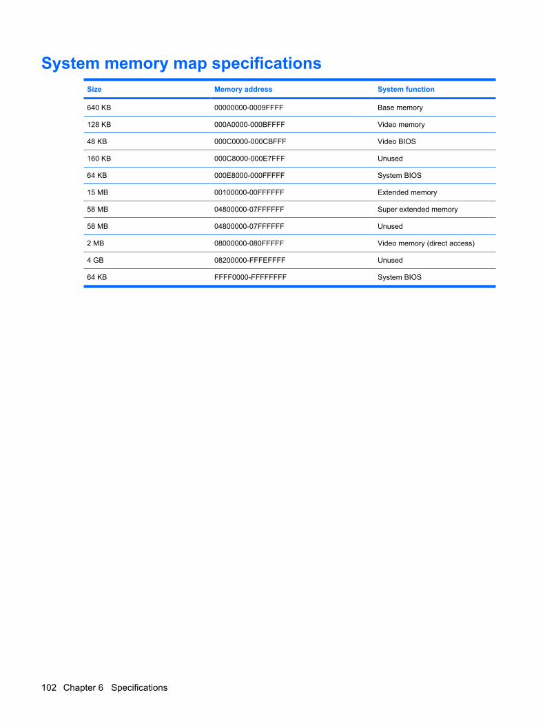
System memory map specificationsSize Memory address System function
640 KB 00000000-0009FFFF Base memory
128 KB 000A0000-000BFFFF Video memory
48 KB 000C0000-000CBFFF Video BIOS
160 KB 000C8000-000E7FFF Unused
64 KB 000E8000-000FFFFF System BIOS
15 MB 00100000-00FFFFFF Extended memory
58 MB 04800000-07FFFFFF Super extended memory
58 MB 04800000-07FFFFFF Unused
2 MB 08000000-080FFFFF Video memory (direct access)
4 GB 08200000-FFFEFFFF Unused
64 KB FFFF0000-FFFFFFFF System BIOS
102 Chapter 6 Specifications
7 Screw listing
This section provides specification and reference information for the screws used in the computer. Thescrews listed in this section are available in the Screw Kit, spare part number 486622-001, or the DisplayScrew Kit, spare part number 486557-001.
103
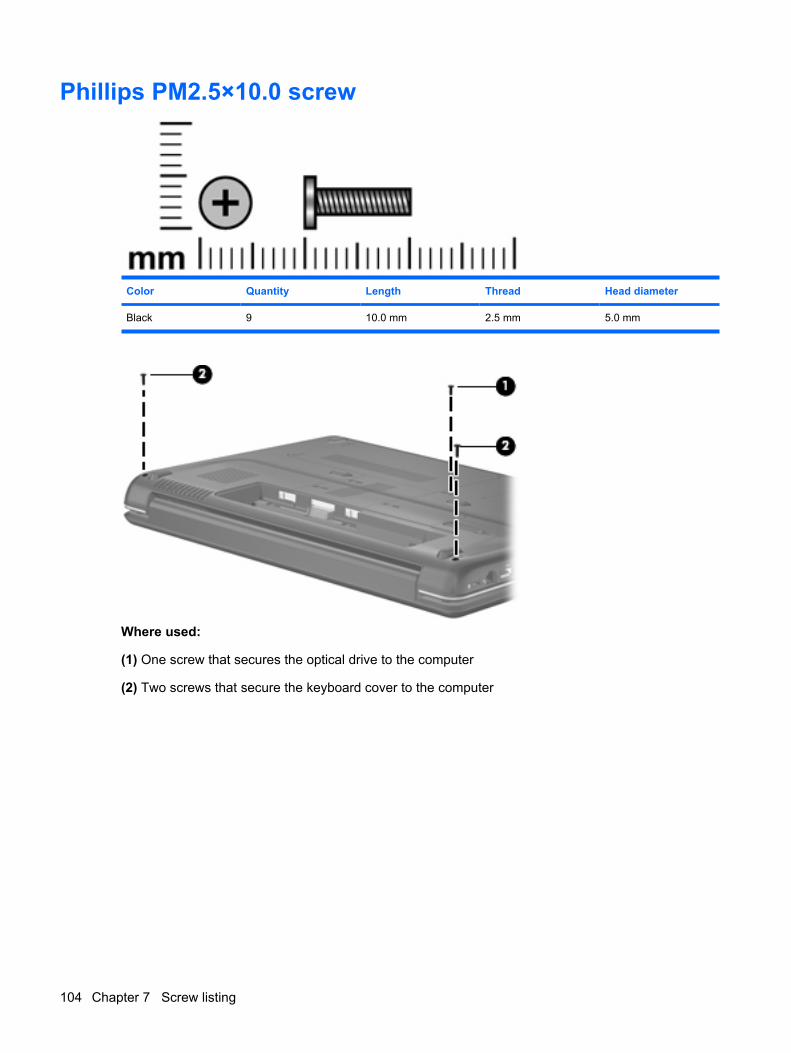
Phillips PM2.5×10.0 screw
Color Quantity Length Thread Head diameter
Black 9 10.0 mm 2.5 mm 5.0 mm
Where used:
(1) One screw that secures the optical drive to the computer
(2) Two screws that secure the keyboard cover to the computer
104 Chapter 7 Screw listing
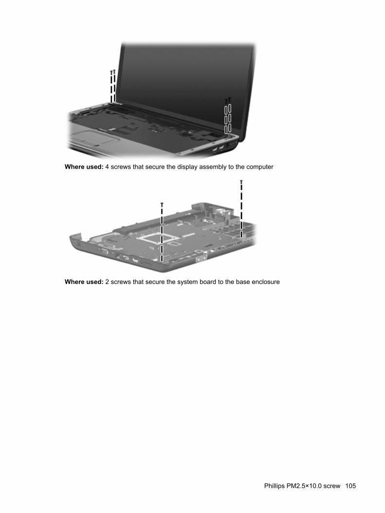
Where used: 4 screws that secure the display assembly to the computer
Where used: 2 screws that secure the system board to the base enclosure
Phillips PM2.5×10.0 screw 105
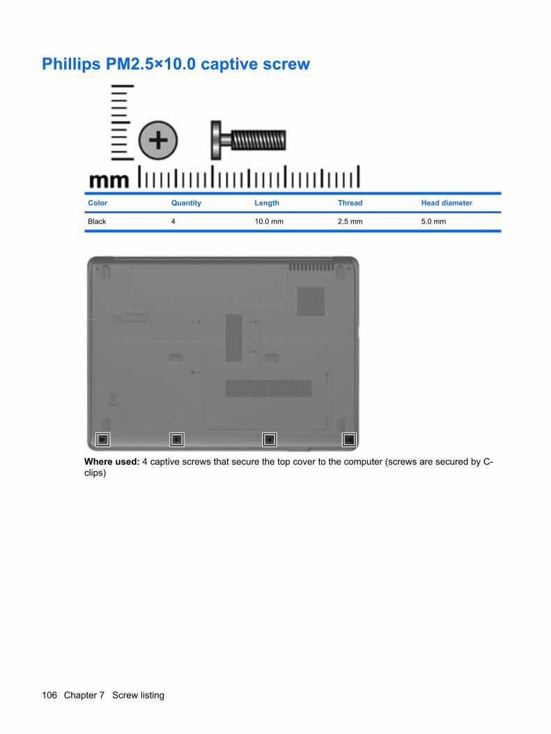
Phillips PM2.5×10.0 captive screw
Color Quantity Length Thread Head diameter
Black 4 10.0 mm 2.5 mm 5.0 mm
Where used: 4 captive screws that secure the top cover to the computer (screws are secured by C-clips)
106 Chapter 7 Screw listing
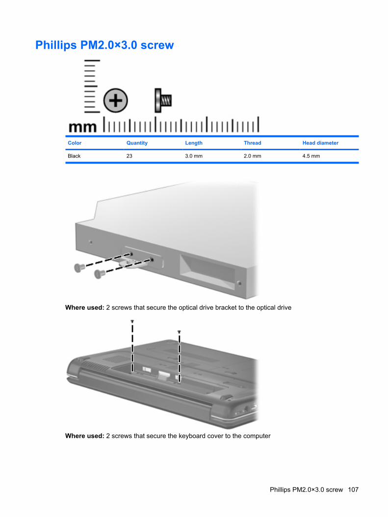
Phillips PM2.0×3.0 screw
Color Quantity Length Thread Head diameter
Black 23 3.0 mm 2.0 mm 4.5 mm
Where used: 2 screws that secure the optical drive bracket to the optical drive
Where used: 2 screws that secure the keyboard cover to the computer
Phillips PM2.0×3.0 screw 107
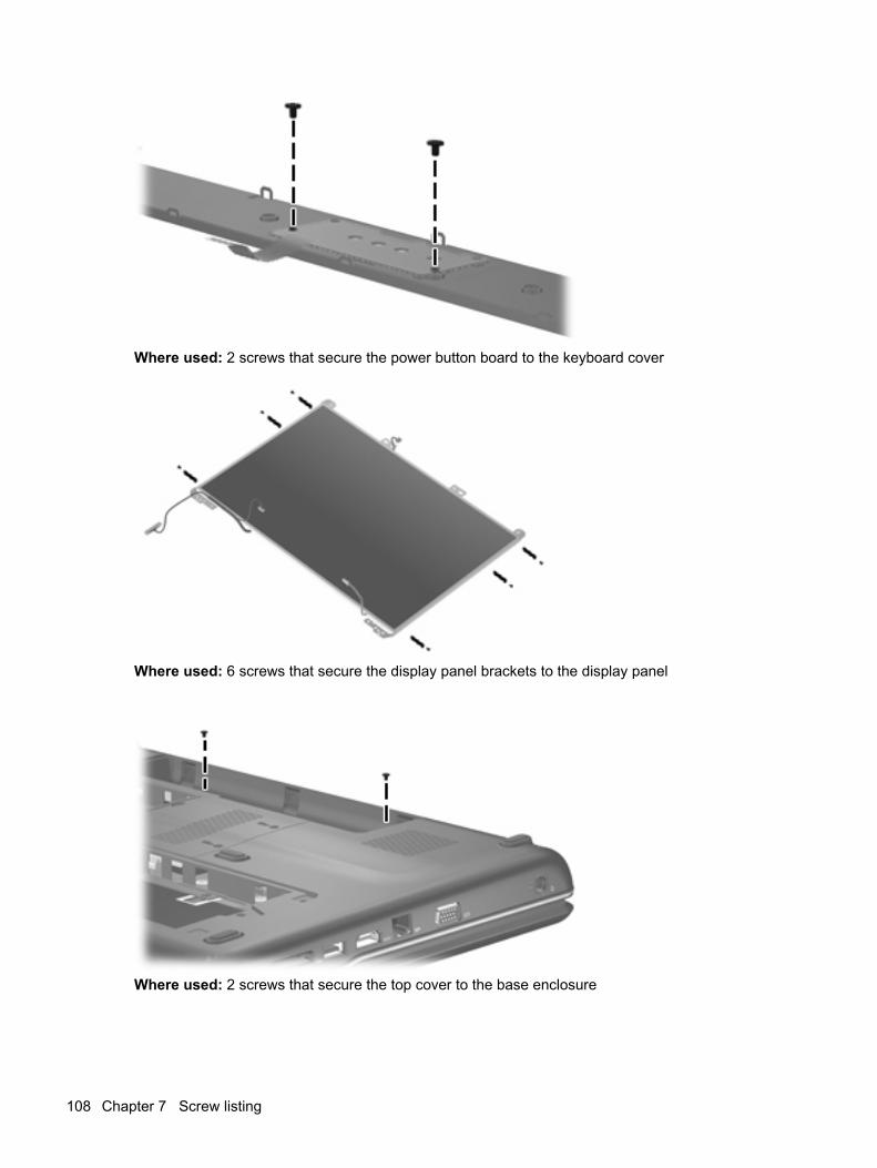
Where used: 2 screws that secure the power button board to the keyboard cover
Where used: 6 screws that secure the display panel brackets to the display panel
Where used: 2 screws that secure the top cover to the base enclosure
108 Chapter 7 Screw listing
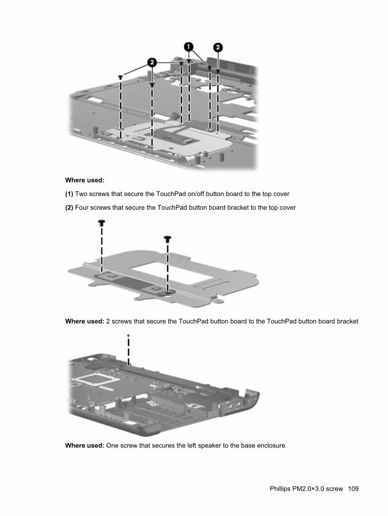
Where used:
(1) Two screws that secure the TouchPad on/off button board to the top cover
(2) Four screws that secure the TouchPad button board bracket to the top cover
Where used: 2 screws that secure the TouchPad button board to the TouchPad button board bracket
Where used: One screw that secures the left speaker to the base enclosure
Phillips PM2.0×3.0 screw 109
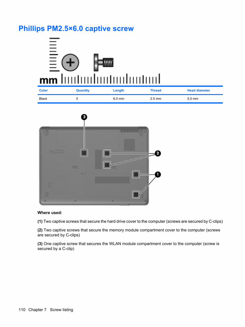
Phillips PM2.5×6.0 captive screw
Color Quantity Length Thread Head diameter
Black 5 6.0 mm 2.5 mm 5.0 mm
Where used:
(1) Two captive screws that secure the hard drive cover to the computer (screws are secured by C-clips)
(2) Two captive screws that secure the memory module compartment cover to the computer (screwsare secured by C-clips)
(3) One captive screw that secures the WLAN module compartment cover to the computer (screw issecured by a C-clip)
110 Chapter 7 Screw listing
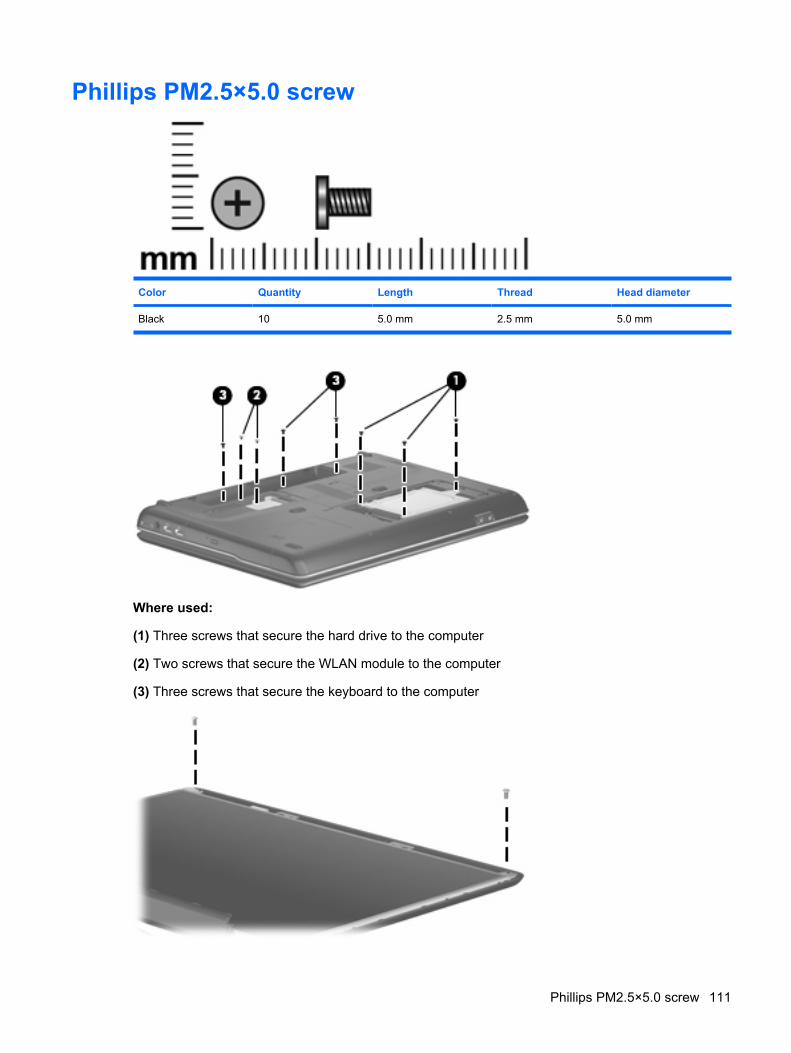
Phillips PM2.5×5.0 screw
Color Quantity Length Thread Head diameter
Black 10 5.0 mm 2.5 mm 5.0 mm
Where used:
(1) Three screws that secure the hard drive to the computer
(2) Two screws that secure the WLAN module to the computer
(3) Three screws that secure the keyboard to the computer
Phillips PM2.5×5.0 screw 111

Where used: 2 screws that secure the display panel to the display enclosure
112 Chapter 7 Screw listing
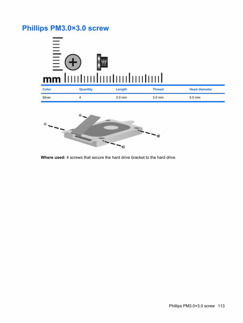
Phillips PM3.0×3.0 screw
Color Quantity Length Thread Head diameter
Silver 4 3.0 mm 3.0 mm 5.0 mm
Where used: 4 screws that secure the hard drive bracket to the hard drive
Phillips PM3.0×3.0 screw 113
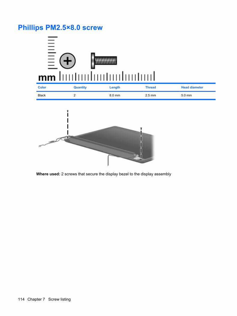
Phillips PM2.5×8.0 screw
Color Quantity Length Thread Head diameter
Black 2 8.0 mm 2.5 mm 5.0 mm
Where used: 2 screws that secure the display bezel to the display assembly
114 Chapter 7 Screw listing
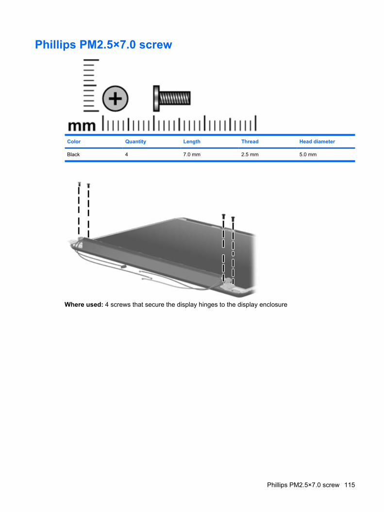
Phillips PM2.5×7.0 screw
Color Quantity Length Thread Head diameter
Black 4 7.0 mm 2.5 mm 5.0 mm
Where used: 4 screws that secure the display hinges to the display enclosure
Phillips PM2.5×7.0 screw 115
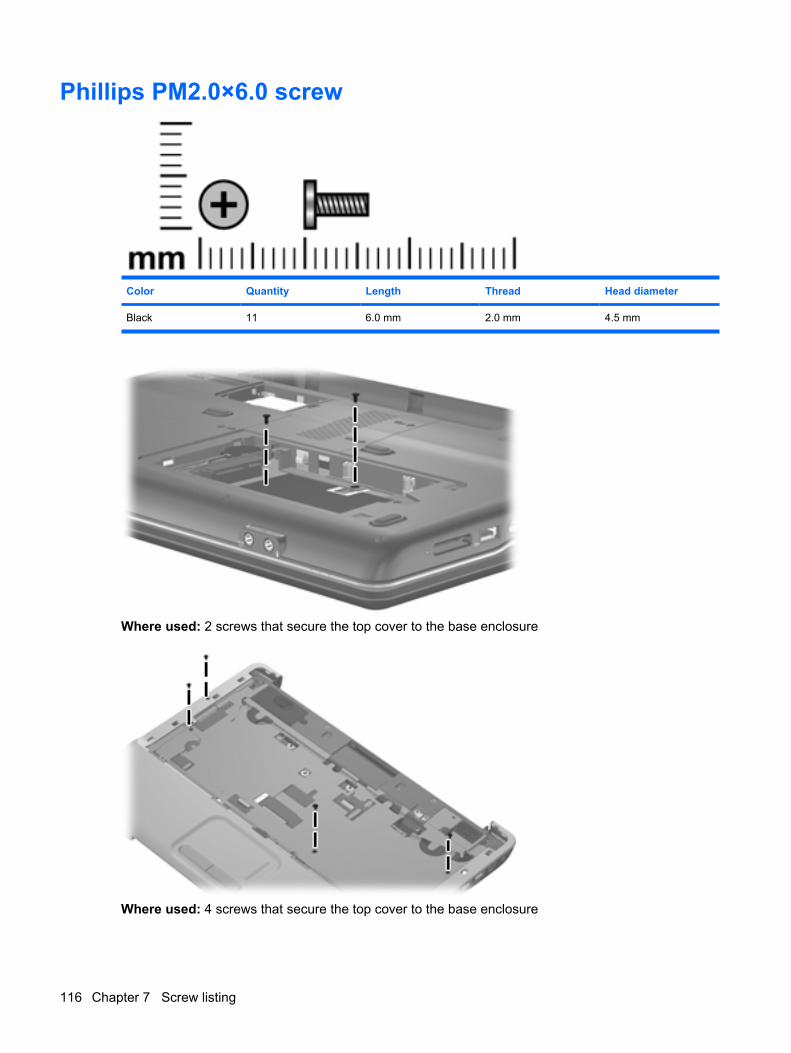
Phillips PM2.0×6.0 screw
Color Quantity Length Thread Head diameter
Black 11 6.0 mm 2.0 mm 4.5 mm
Where used: 2 screws that secure the top cover to the base enclosure
Where used: 4 screws that secure the top cover to the base enclosure
116 Chapter 7 Screw listing
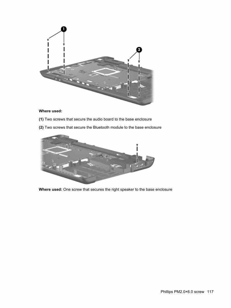
Where used:
(1) Two screws that secure the audio board to the base enclosure
(2) Two screws that secure the Bluetooth module to the base enclosure
Where used: One screw that secures the right speaker to the base enclosure
Phillips PM2.0×6.0 screw 117
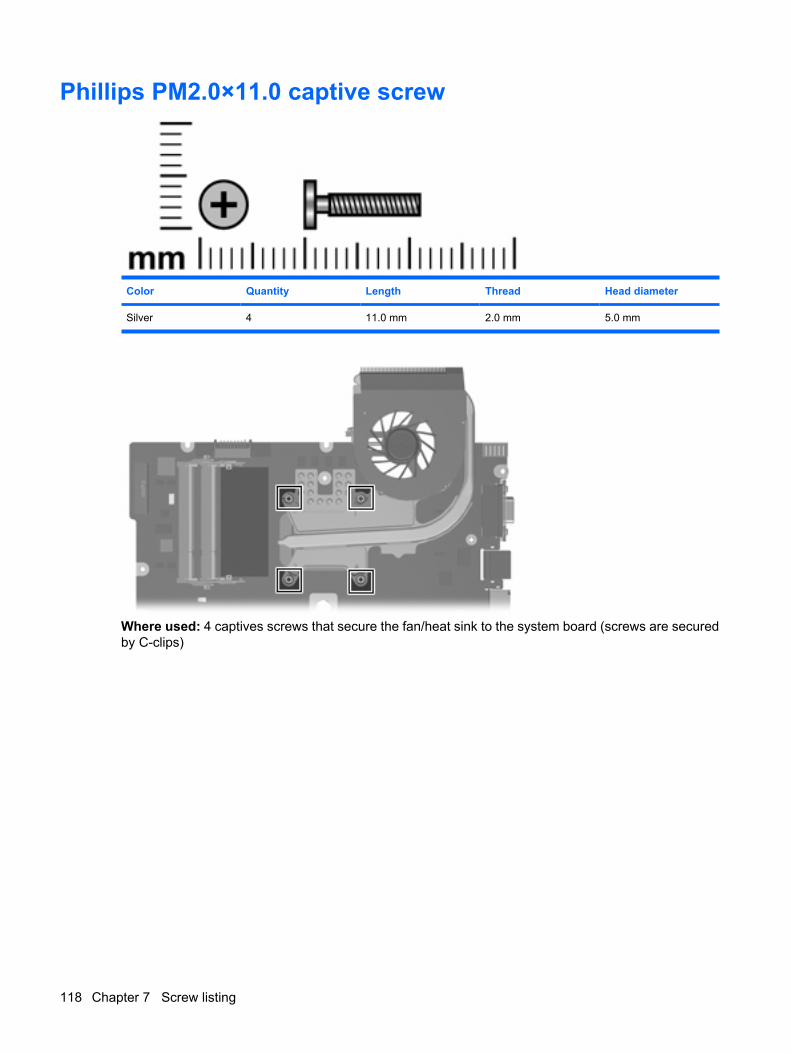
Phillips PM2.0×11.0 captive screw
Color Quantity Length Thread Head diameter
Silver 4 11.0 mm 2.0 mm 5.0 mm
Where used: 4 captives screws that secure the fan/heat sink to the system board (screws are securedby C-clips)
118 Chapter 7 Screw listing
8 Backup and recovery
Recovering system informationRecovery after a system failure is as complete as your most current backup. HP recommends that youcreate recovery discs immediately after software setup. As you add new software and data files, youshould continue to back up your system on a regular basis to maintain a reasonably current backup.
Tools provided by the operating system and Recovery Manager software are designed to help you withthe following tasks for safeguarding your information and restoring it in case of a system failure:
● Making a set of recovery discs (Recovery Manager software feature). Recovery discs are used tostart up (boot) your computer and restore the operating system and software programs to factorysettings in case of system failure or instability.
● Backing up your information regularly to protect your important system files.
● Creating system restore points (operating system feature). System restore points allow you toreverse undesirable changes to your computer by restoring the computer to an earlier state.
● Recovering a program or driver (Recovery Manager software feature). This feature helps youreinstall a program or driver without performing a full system recovery.
● Performing a full system recovery (Recovery Manager software feature). With Recovery Manager,you can recover your full factory image if you experience system failure or instability. RecoveryManager works from a dedicated recovery partition (select models only) on the hard drive or fromrecovery discs you create.
NOTE: If your computer includes a solid-state drive (SSD), you may not have a recovery partition.Recovery discs have been included for computers that do not have a partition. Use these discs torecover your operating system and software. To check for the presence of a recovery partition,select Start > Computer. If the partition is present, an HP Recovery drive is listed in the Hard DiskDrives section of the window.
Creating recovery discsNOTE: HP recommends that you create recovery discs to be sure that you can restore your systemto its original factory state if you experience serious system failure or instability. Create these discs aftersetting up the computer for the first time.
NOTE: Handle these discs carefully and keep them in a safe place. The software allows the creationof only one set of recovery discs.
Recovering system information 119
Note the following guidelines before creating recovery discs:
● You will need high quality CD-R, DVD-R, double-layer DVD-R, DVD+R, double-layer DVD+R, orBD-R (writable Blu-ray) discs. All these discs are purchased separately.
NOTE: Read-write discs, such as CD-RW, DVD±RW, double-layer DVD±RW, and BD-RE(rewritable Blu-ray) discs, are not compatible with the Recovery Manager software.
● The computer must be connected to AC power during this process.
● Only one set of recovery discs can be created per computer.
● Number each disc before inserting it into the computer optical drive.
● If necessary, you can exit the program before you have finished creating the recovery discs. Thenext time you open Recovery Manager, you will be prompted to continue the disc creation process.
To create a set of recovery discs:
1. Select Start > All Programs > Recovery Manager > Recovery Manager.
Recovery Manager opens.
2. Click Advanced Options.
NOTE: If you are operating the computer on battery power, you will be prompted to connect toAC power before you can go to the next step.
3. Click Recovery disc creation, and then click Next.
4. Follow the on-screen instructions.
Backing up your information
When to back up
● On a regularly scheduled basis
NOTE: Set reminders to back up your information periodically.
● Before the computer is repaired or restored
● Before you add or modify hardware or software
Backup suggestions
● Create a set of recovery discs using Recovery Manager.
● Create system restore points using the Windows® System Restore feature, and periodically copythem to disc.
● Store personal files in the Documents folder and back up these folders periodically.
● Back up templates stored in their associated programs.
● Save customized settings in a window, toolbar, or menu bar by taking a screen shot of your settings.The screen shot can be a time saver if you have to reset your preferences.
120 Chapter 8 Backup and recovery
To copy the screen and paste it into a word-processing document, follow these steps:
a. Display the screen.
b. Copy the screen:
To copy only the active window, press alt+fn+prt sc.
To copy the entire screen, press fn+prt sc.
c. Open a word-processing document, and then select Edit > Paste.
Using system restore pointsWhen you back up your system, you are creating a system restore point. A system restore point allowsyou to save and name a snapshot of your hard drive at a specific point in time. You can then recoverback to that point if you want to reverse subsequent changes made to your system.
NOTE: Recovering to an earlier restore point does not affect data files saved or e-mails created sincethe last restore point.
You also can create additional restore points to provide increased protection for your system files andsettings.
When to create restore points
● Before you add or extensively modify software or hardware
● Periodically, whenever the system is performing optimally
NOTE: If you revert to a restore point and then change your mind, you can reverse the restoration.
Create a system restore point1. Select Start > Control Panel > System and Maintenance > System.
2. In the left pane, click System protection.
3. Click the System Protection tab.
4. Under Automatic restore points, select the disk for which you want to create a restore point.
5. Click Create.
The System Protection window opens.
6. Follow the on-screen instructions.
Restore to a previous date and timeTo revert to a restore point (created at a previous date and time), when the computer was functioningoptimally, follow these steps:
1. Select Start > Control Panel > System and Maintenance > System.
2. In the left pane, click System protection.
3. Click the System Protection tab.
Recovering system information 121
4. Click the System Restore button, and then click Next.
The System Restore window opens.
5. Follow the on-screen instructions.
122 Chapter 8 Backup and recovery
Performing a recoveryNOTE: You can recover only files that you have previously backed up. HP recommends that you useRecovery Manager to create an entire drive backup as soon as you set up your computer.
Recovery Manager software allows you to repair or restore the system if you experience system failureor instability. Recovery Manager works from recovery discs that you create or from a dedicated recoverypartition (select models only) on the hard drive. However, if your computer includes a solid-state drive(SSD), you may not have a recovery partition. If that is the case, recovery discs have been includedwith your computer. Use these discs to recover your operating system and software.
NOTE: Windows has its own built-in repair features, such as System Restore and driver roll-backcapabilities. If you have not already tried these features, try them before using Recovery Manager.
NOTE: Recovery Manager recovers only software that was preinstalled at the factory. Software notprovided with this computer must be downloaded from the manufacturer's Web site or reinstalled fromthe disc provided by the manufacturer.
Recovering from the recovery discsTo restore the system from the recovery discs:
1. Back up all personal files.
2. Insert the first recovery disc into the optical drive and restart the computer.
3. Follow the on-screen instructions.
Recovering from the dedicated recovery partition (select models only)
NOTE: If your computer includes a solid-state drive (SSD), you may not have a recovery partition. Youwill not be able to recover using this procedure. Recovery discs have been included for computers thatdo not have a partition. Use these discs to recover your operating system and software.
On some models, you can perform a recovery from the partition on the hard drive from either the Startbutton or f11.
To restore the system from the partition, follow these steps:
1. Access Recovery Manager in either of the following ways:
● Select Start > All Programs > Recovery Manager > Recovery Manager.
–or–
● Restart the computer and press f11 while the “Press <F11> for recovery” message is displayedon the screen. Then select Recovery Manager.
Recovery Manager opens.
2. Click Advanced Options.
3. Click System recovery, and then click Next.
4. Follow the on-screen instructions.
Recovering system information 123
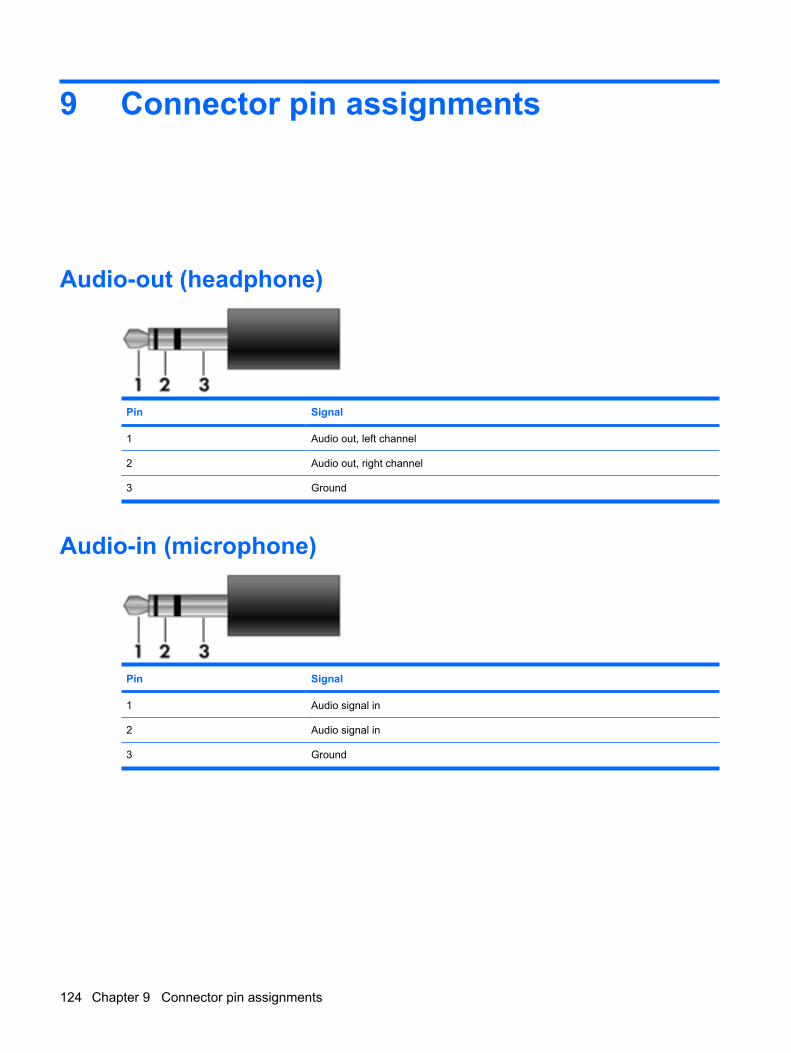
9 Connector pin assignments
Audio-out (headphone)
Pin Signal
1 Audio out, left channel
2 Audio out, right channel
3 Ground
Audio-in (microphone)
Pin Signal
1 Audio signal in
2 Audio signal in
3 Ground
124 Chapter 9 Connector pin assignments
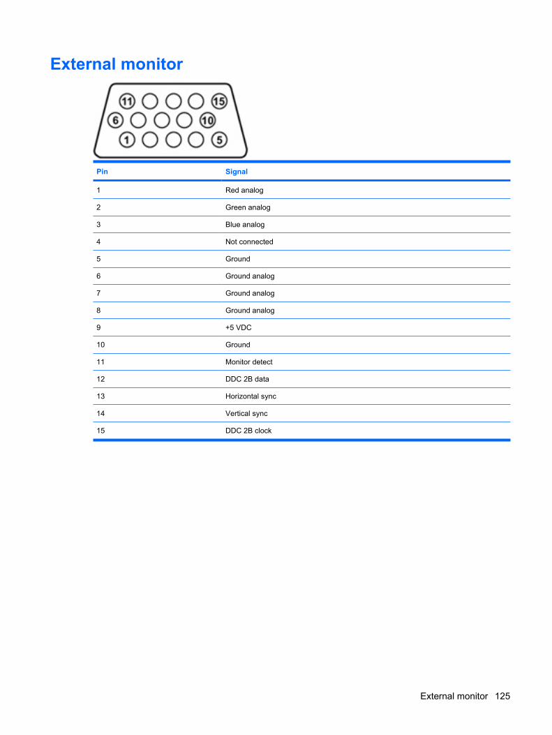
External monitor
Pin Signal
1 Red analog
2 Green analog
3 Blue analog
4 Not connected
5 Ground
6 Ground analog
7 Ground analog
8 Ground analog
9 +5 VDC
10 Ground
11 Monitor detect
12 DDC 2B data
13 Horizontal sync
14 Vertical sync
15 DDC 2B clock
External monitor 125
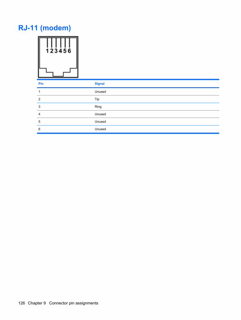
RJ-11 (modem)
Pin Signal
1 Unused
2 Tip
3 Ring
4 Unused
5 Unused
6 Unused
126 Chapter 9 Connector pin assignments
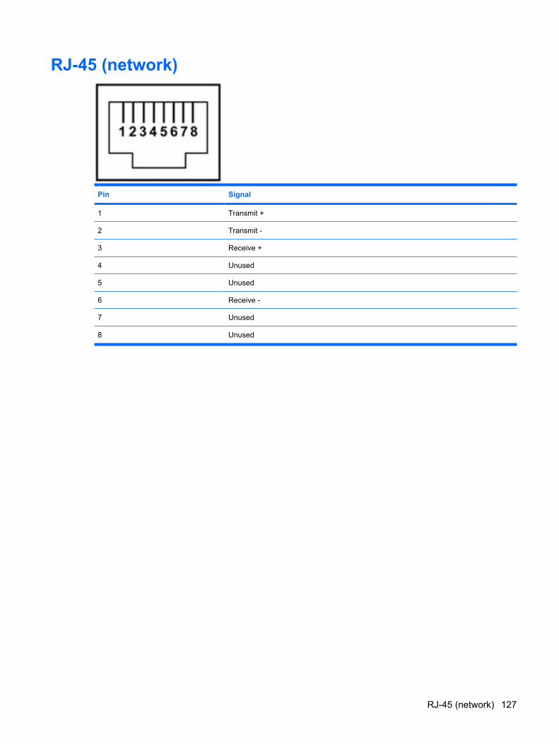
RJ-45 (network)
Pin Signal
1 Transmit +
2 Transmit -
3 Receive +
4 Unused
5 Unused
6 Receive -
7 Unused
8 Unused
RJ-45 (network) 127
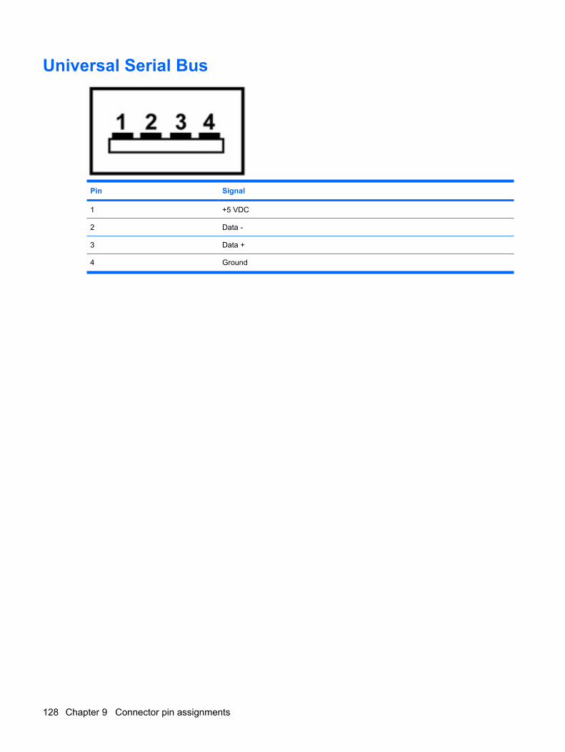
Universal Serial Bus
Pin Signal
1 +5 VDC
2 Data -
3 Data +
4 Ground
128 Chapter 9 Connector pin assignments
10 Power cord set requirements
The wide range input feature of the computer permits it to operate from any line voltage from 100 to 120volts AC or from 220 to 240 volts AC.
The 3-conductor power cord set included with the computer meets the requirements for use in thecountry or region where the equipment is purchased.
Power cord sets for use in other countries and regions must meet the requirements of the country orregion where the computer is used.
Requirements for all countries and regionsThe requirements listed below are applicable to all countries and regions:
● The length of the power cord set must be at least 1.5 m (5.0 ft) and no more than 2.0 m (6.5 ft).
● All power cord sets must be approved by an acceptable accredited agency responsible forevaluation in the country or region where the power cord set will be used.
● The power cord sets must have a minimum current capacity of 10 amps and a nominal voltagerating of 125 or 250 V AC, as required by the power system of each country or region.
● The appliance coupler must meet the mechanical configuration of an EN 60 320/IEC 320 StandardSheet C13 connector for mating with the appliance inlet on the back of the computer.
Requirements for all countries and regions 129
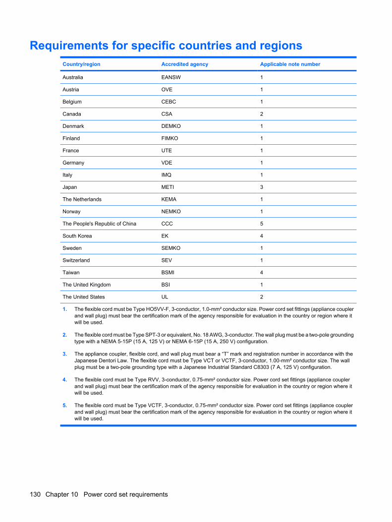
Requirements for specific countries and regionsCountry/region Accredited agency Applicable note number
Australia EANSW 1
Austria OVE 1
Belgium CEBC 1
Canada CSA 2
Denmark DEMKO 1
Finland FIMKO 1
France UTE 1
Germany VDE 1
Italy IMQ 1
Japan METI 3
The Netherlands KEMA 1
Norway NEMKO 1
The People's Republic of China CCC 5
South Korea EK 4
Sweden SEMKO 1
Switzerland SEV 1
Taiwan BSMI 4
The United Kingdom BSI 1
The United States UL 2
1. The flexible cord must be Type HO5VV-F, 3-conductor, 1.0-mm² conductor size. Power cord set fittings (appliance couplerand wall plug) must bear the certification mark of the agency responsible for evaluation in the country or region where itwill be used.
2. The flexible cord must be Type SPT-3 or equivalent, No. 18 AWG, 3-conductor. The wall plug must be a two-pole groundingtype with a NEMA 5-15P (15 A, 125 V) or NEMA 6-15P (15 A, 250 V) configuration.
3. The appliance coupler, flexible cord, and wall plug must bear a “T” mark and registration number in accordance with theJapanese Dentori Law. The flexible cord must be Type VCT or VCTF, 3-conductor, 1.00-mm² conductor size. The wallplug must be a two-pole grounding type with a Japanese Industrial Standard C8303 (7 A, 125 V) configuration.
4. The flexible cord must be Type RVV, 3-conductor, 0.75-mm² conductor size. Power cord set fittings (appliance couplerand wall plug) must bear the certification mark of the agency responsible for evaluation in the country or region where itwill be used.
5. The flexible cord must be Type VCTF, 3-conductor, 0.75-mm² conductor size. Power cord set fittings (appliance couplerand wall plug) must bear the certification mark of the agency responsible for evaluation in the country or region where itwill be used.
130 Chapter 10 Power cord set requirements
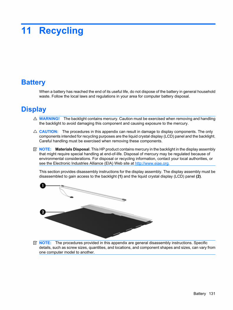
11 Recycling
BatteryWhen a battery has reached the end of its useful life, do not dispose of the battery in general householdwaste. Follow the local laws and regulations in your area for computer battery disposal.
DisplayWARNING! The backlight contains mercury. Caution must be exercised when removing and handlingthe backlight to avoid damaging this component and causing exposure to the mercury.
CAUTION: The procedures in this appendix can result in damage to display components. The onlycomponents intended for recycling purposes are the liquid crystal display (LCD) panel and the backlight.Careful handling must be exercised when removing these components.
NOTE: Materials Disposal. This HP product contains mercury in the backlight in the display assemblythat might require special handling at end-of-life. Disposal of mercury may be regulated because ofenvironmental considerations. For disposal or recycling information, contact your local authorities, orsee the Electronic Industries Alliance (EIA) Web site at http://www.eiae.org.
This section provides disassembly instructions for the display assembly. The display assembly must bedisassembled to gain access to the backlight (1) and the liquid crystal display (LCD) panel (2).
NOTE: The procedures provided in this appendix are general disassembly instructions. Specificdetails, such as screw sizes, quantities, and locations, and component shapes and sizes, can vary fromone computer model to another.
Battery 131
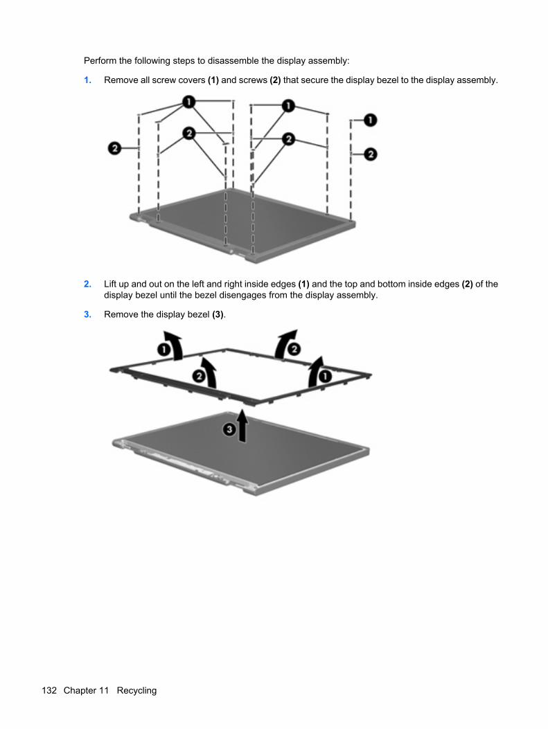
Perform the following steps to disassemble the display assembly:
1. Remove all screw covers (1) and screws (2) that secure the display bezel to the display assembly.
2. Lift up and out on the left and right inside edges (1) and the top and bottom inside edges (2) of thedisplay bezel until the bezel disengages from the display assembly.
3. Remove the display bezel (3).
132 Chapter 11 Recycling
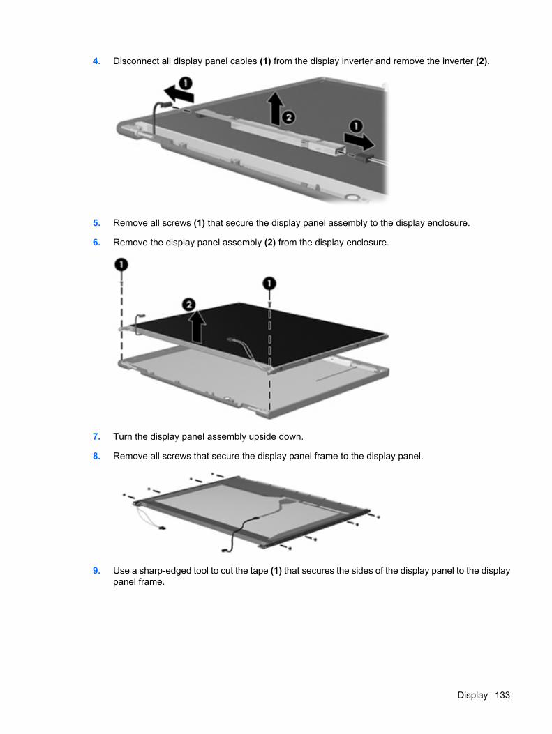
4. Disconnect all display panel cables (1) from the display inverter and remove the inverter (2).
5. Remove all screws (1) that secure the display panel assembly to the display enclosure.
6. Remove the display panel assembly (2) from the display enclosure.
7. Turn the display panel assembly upside down.
8. Remove all screws that secure the display panel frame to the display panel.
9. Use a sharp-edged tool to cut the tape (1) that secures the sides of the display panel to the displaypanel frame.
Display 133
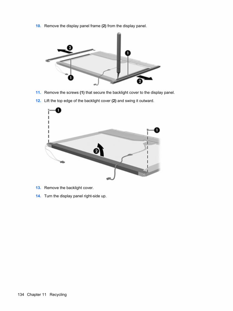
10. Remove the display panel frame (2) from the display panel.
11. Remove the screws (1) that secure the backlight cover to the display panel.
12. Lift the top edge of the backlight cover (2) and swing it outward.
13. Remove the backlight cover.
14. Turn the display panel right-side up.
134 Chapter 11 Recycling
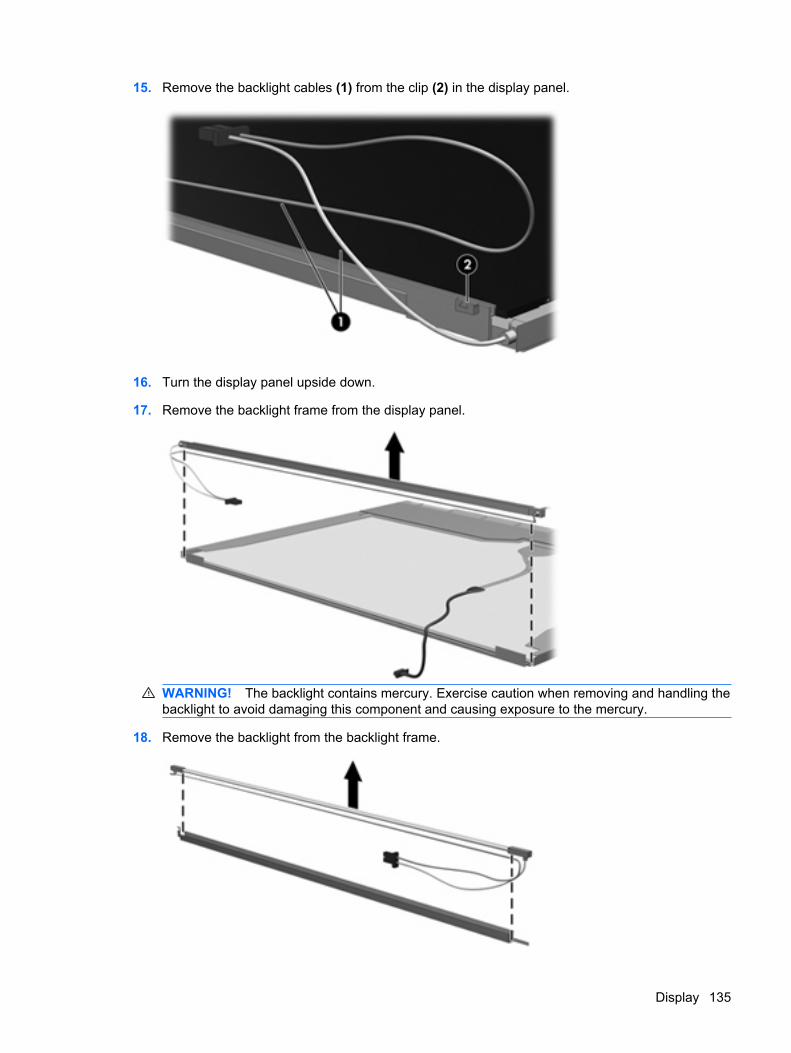
15. Remove the backlight cables (1) from the clip (2) in the display panel.
16. Turn the display panel upside down.
17. Remove the backlight frame from the display panel.
WARNING! The backlight contains mercury. Exercise caution when removing and handling thebacklight to avoid damaging this component and causing exposure to the mercury.
18. Remove the backlight from the backlight frame.
Display 135
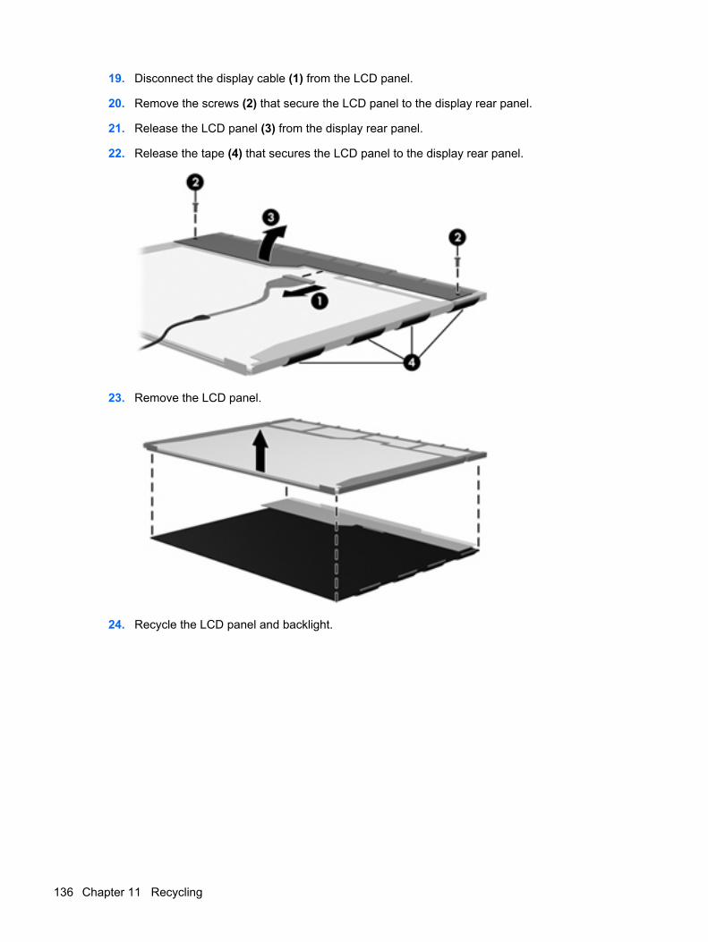
19. Disconnect the display cable (1) from the LCD panel.
20. Remove the screws (2) that secure the LCD panel to the display rear panel.
21. Release the LCD panel (3) from the display rear panel.
22. Release the tape (4) that secures the LCD panel to the display rear panel.
23. Remove the LCD panel.
24. Recycle the LCD panel and backlight.
136 Chapter 11 Recycling
Index
Symbols/Numerics1394 Power Saving 91
AAC adapter light 12AC adapter, spare part
number 25, 26administrator password 90antenna
disconnecting 51locations 6removal 62spare part number 22, 29,
63audio board
removal 70spare part number 18, 29,
70audio, product description 3audio-in jack
location 10pin assignments 124
audio-out jacklocation 10pin assignments 124
Bbackup 120base enclosure, spare part
numbers 18, 29, 31battery
location 13removal 40spare part numbers 18, 27,
28, 40battery bay 13battery latch 13battery light 10
Blu-ray BD-ROM with SuperMultiDVD±RW and CD-RW Double-Layer Combo Drive
removal 41spare part numbers 21, 24,
28, 41specifications 97
Bluetooth moduleremoval 71spare part number 18, 27,
71Bluetooth module cable, spare part
number 18, 27, 29, 71boot options 91boot order 91bottom components 13button components 7button sound 91buttons
power 7TouchPad 9
Ccables, service considerations 33Card Reader Power Saving 91changing the Setup Utility
language 85chipset, product description 2CMOS clearing 37components
bottom 13buttons 7display 6front 10keys 8left-side 12rear 11right-side 11top 6TouchPad 9
computer feetlocations 39spare part number 39
computer specifications 93connectors
power 12service considerations 33
DDiagnostics menu 92Digital Media Slot 12Digital Media Slot light 12diskette drive
precautions 33product description 3
display assemblyremoval 57spare part numbers 16, 28,
30, 57display bezel
illustrated 22removal 59spare part numbers 22, 28,
29, 30, 59display components
recycling 131spare part numbers 22
display enclosureillustrated 23spare part numbers 23, 28,
30display hinge
illustrated 22removal 61spare part number 22, 28,
61Display Hinge Kit, spare part
number 22, 28, 61display inverter
illustrated 22
Index 137
removal 60spare part number 22, 28,
61display panel
illustrated 22product description 2removal 61spare part number 22, 27,
62display panel brackets
illustrated 22removal 62spare part number 22, 28,
62display panel cable, spare part
number 22, 29Display Rubber Kit, spare part
number 23, 29, 59Display Screw Kit, spare part
number 23, 28, 59display specifications 94displaying system information 86docking support, product
description 4drive light 10drives
preventing damage 33drives, boot order 91DVD±RW and CD-RW Combo
Driveprecautions 33removal 41spare part numbers 21, 24,
28, 41specifications 96
Eelectrostatic discharge 34esc key 8Ethernet, product description 3exiting the Setup Utility 88external media cards, product
description 4external monitor port
location 12pin assignments 125
Ff11 123fan always on 91
fan/heat sink assemblyremoval 79spare part number 18, 29,
79feet
locations 39spare part number 39
fingerprint reader 85fn key 8front components 10full system recovery 119function keys 8
Ggraphics, product description 2grounding equipment and
methods 36
Hhard drive
location 13precautions 33product description 3removal 43spare part numbers 18, 24,
28, 31, 43specifications 95
hard drive bay 13hard drive bracket, removal 45hard drive cover
illustrated 23removal 44
Hard Drive Hardware Kit, spare partnumber 19, 24, 28, 43
hard drive self test 92HDMI port 12headphone jack
location 10pin assignments 124
II/O address specifications 100interrupt specifications 99
Jjacks
audio-in 10audio-out 10headphone 10microphone 10modem 11
network 12RJ-11 11RJ-45 12
Kkeyboard
product description 4removal 52spare part numbers 16, 29,
52keyboard cover
removal 54spare part number 16, 29,
54keypad keys 8keys
esc 8fn 8function 8keypad 8volume 8Windows applications 8Windows logo 8
LLAN Power Saving 91language support 91left-side components 12lights
AC adapter 12battery 10Digital Media Slot 12drive 10optical drive 11power 10
MMain menu 89mass storage devices, spare part
numbers 24memory map specifications 102memory module
product description 2removal 47spare part numbers 19, 27,
47memory module compartment 13memory module compartment
coverremoval 47
memory test 92
138 Index
microphoneillustrated 22locations 7product description 3removal 63spare part number 22, 29,
63microphone jack
location 10pin assignments 124
model name 1modem jack
location 11pin assignments 126
modem module, productdescription 3
monitor portlocation 12pin assignments 125
Nnavigating in the Setup Utility 86network jack
location 12pin assignments 127
Ooperating system, product
description 4optical drive
location 11precautions 33product description 3removal 41spare part numbers 21, 24,
41specifications 96, 97
optical drive light 11
Ppacking guidelines 35password clearing 37passwords 90pin assignments
audio-in jack 124audio-out jack 124external monitor port 125headphone jack 124microphone jack 124modem jack 126monitor port 125
network jack 127RJ-11 126RJ-45 jack 127Universal Serial Bus (USB)
port 128plastic parts 32Plastics Kit
contents 23spare part number 17, 23,
29pointing device components
product description 4TouchPad 9TouchPad buttons 9TouchPad light 9TouchPad on/off button 9vertical scroll zone 9
portsexternal monitor 12HDMI 12monitor 12product description 4Universal Serial Bus
(USB) 11, 12power button 7power button board
removal 56spare part number 16, 29,
56power connector 12power connector cable
removal 83spare part number 18, 29,
83power cord
set requirements 129spare part numbers 25, 30
power light 10power requirements, product
description 4power-on password 90processor
product description 1removal 82spare part numbers 17, 26,
30, 82processor bracket, spare part
number 18, 29, 82Processor C4 State 91
product descriptionaudio 3chipset 2diskette drive 3display panel 2docking support 4Ethernet 3external media cards 4graphics 2hard drives 3keyboard 4memory module 2microphone 3modem module 3operating system 4optical drives 3pointing devices 4ports 4power requirements 4processors 1product name 1security 4serviceability 5webcam 3wireless 3
product name 1
Rrear component 11recovering a program or
driver 119recovering from the dedicated
recovery partition 123recovering from the recovery
discs 123recovery discs 119Recovery Manager 119, 123recovery partition 119recovery, system 123removal/replacement
preliminaries 32procedures 38
restore points 121restoring default settings 87right-side components 11RJ-11 connector cable
removal 77spare part number 18, 29,
77
Index 139
RJ-11 jacklocation 11pin assignments 126
RJ-45 jacklocation 12pin assignments 127
RTC batteryremoval 46spare part number 19, 29,
46Rubber Kit, spare part
number 18, 29
SScrew Kit
contents 103spare part number 25, 29
screw listing 103secondary hard drive self test 92security cable slot 11Security menu 90security, product description 4selecting in the Setup Utility 86serial number 14, 38service considerations 32serviceability, product
description 5Setup Utility
overview 85solid-state drive (SSD) 119,
123speakers
removal 72spare part number 17, 29,
72specifications
Blu-ray BD-ROM withSuperMulti DVD±RW and CD-RW Double-Layer ComboDrive 97
computer 93display 94DVD±RW and CD-RW Combo
Drive 96hard drive 95I/O addresses 100interrupts 99memory map 102optical drive 96, 97system DMA 98
starting the Setup Utility 85static-shielding materials 36supported discs 120system board
removal 74spare part numbers 17, 28,
30, 31, 74System Configuration menu 91system DMA 98system failure or instability 119system information 89system memory map 102system recovery 123system restore points 119
Ttools required 32top components 6top cover
removal 64spare part number 17, 29,
64TouchPad 9TouchPad button board
removal 68spare part number 17, 29,
68TouchPad buttons 9TouchPad components,
illustrated 9TouchPad light 9TouchPad on/off button 9TouchPad on/off button board
removal 66spare part number 17, 29,
66transporting guidelines 35
UUniversal Serial Bus (USB) port
location 11, 12pin assignments 128
unknown password 37USB board
removal 73spare part number 18, 29,
73USB board cable, spare part
number 18, 29, 73
Vvents 11, 13vertical scroll zone 9Virtualization Technology 91Volume keys 8
Wwebcam
location 7product description 3
webcam light 6webcam module
illustrated 22removal 60spare part number 22, 29,
60webcam module cable
illustrated 22spare part number 22, 29
Windows applications key 8Windows logo key 8wireless antenna
disconnecting 51locations 6removal 62spare part number 22, 63
Wireless Antenna Kit, spare partnumber 22
wireless button 7wireless, product description 3WLAN module
removal 49spare part numbers 19, 26,
27, 49WLAN module compartment 13WLAN module compartment cover
illustrated 23removal 51
workstation guidelines 35
140 Index