Embed Size (px)
Citation preview
Pooled Fund TPF-5(139) PCC Surface Characteristics: Tire-Pavement Noise Program Part 3 – Innovative Solutions/Current Practices
HOW TO REDUCE TIRE-PAVEMENT NOISE INTERIM BETTER PRACTICES FOR CONSTRUCTING AND TEXTURING CONCRETE PAVEMENT SURFACES
:
Robert Otto Rasmussen
Sabrina I. Garber Gary J. Fick Theodore R. Ferragut Paul D. Wiegand
July 2008
2711 South Loop Drive, Suite 4700 Ames, IA 50010 Phone: 515-294-5798
www.SurfaceCharacteristics.com
www.CPTechCenter.org

Table of Contents
List of Figures ...........................................................................................v Key Concepts ...........................................................................................vi 1 Background ...................................................................................... 1 2 Summary of Better Practices ........................................................ 4 3 Overview of Concrete Pavement Texturing .................................. 7
3.1 Texture Classifications .............................................................................7 3.2 Variables affecting Texture ......................................................................8 3.3 Nominal Surface Texture..........................................................................9 3.4 Texture Measurement............................................................................ 10
4 Controlling Concrete Pavement Surface Texture ......................11 4.1 Concrete Materials................................................................................. 13 4.2 Tining........................................................................................................ 14
4.2.1 Concrete Material ......................................................................................14 4.2.2 Equipment...................................................................................................15 4.2.3 Construction Technique.............................................................................15 4.2.4 Spacing........................................................................................................15 4.2.5 Width ...........................................................................................................16 4.2.6 Depth ...........................................................................................................16 4.2.7 Knowledge Gaps ........................................................................................16
4.3 Drag.......................................................................................................... 17 4.3.1 Drag Material..............................................................................................17 4.3.2 Construction Technique.............................................................................18 4.3.3 Knowledge Gaps ........................................................................................18
4.4 Diamond Grinding .................................................................................. 19 4.4.1 Project Selection........................................................................................19 4.4.2 Grinding Head.............................................................................................19 4.4.3 Equipment Operation ................................................................................19 4.4.4 Knowledge Gaps ........................................................................................19
4.5 Making Field Adjustments .................................................................... 20 4.6 Other Considerations............................................................................. 20
4.6.1 Steering and Elevation Controls...............................................................20 4.6.2 Crown and Cross-Slope Changes .............................................................20 4.6.3 Workmanship and Ownership ..................................................................21 4.6.4 Texturing Speed .........................................................................................22 4.6.5 Matching Start and Stop Points ...............................................................22
iii
4.6.6 Curing Impacts on Texturing.....................................................................
................................................................. ....................................
....................................................................................... ..................................................................................................................................................................................................................
................................................................................................................................................................................
..................................................................................................................................................................
..............................................................................................................................................................................
................................................................................. ......................................................................................
............................................................................................
...............................................................23
4.6.7 Over Vibration and Segregation 23 4.7 Inspecting Surface Textures 23
5 Equipment Operation and Maintenance 24 5.1 Concrete Paver 24
5.1.1 Frame 25 5.1.2 Sensors 27 5.1.3 Augers / Spreader (Plow) 28 5.1.4 Vibrators 30 5.1.5 Strike Off, Floats, and Forming Pan 31 5.1.6 Tracks 34 5.1.7 Miscellaneous 35 5.1.8 Cleaning Techniques 35
5.2 Texture Equipment 35 5.2.1 Frame and Engine 37 5.2.2 Tracks or Tires 37 5.2.3 Texture Attachments .................................................................................
...........................................................................................................................................................................................
.................................................................................... ...........................................................................................
.....................................................................................................................................................................
..................................................................................................................................
.............................
39 5.2.4 Curing Equipment 41 5.2.5 Summary 42
5.3 Diamond Grinder 43 5.3.1 Grinding Heads 43 5.3.2 General Maintenance 45 5.3.3 Hydraulic Systems 45
References 46 Appendix A: Tine Length, Angle, and Height 47 Appendix B: Texturing Better Practices Checklist 49 Appendix C: Definitions ........................................................................
.....................................................................................................................................................................
.............................................................................................................
51 Appendix D: For More Information 52
Reports 52 Websites 52
iv

List of Figures
Figure 1. Normalized distributions of OBSI noise levels for conventional concrete pavement textures....................... .........................................................
. ..........................................................................
2 Figure 2. Concrete pavement surface properties that affect tire-pavement noise. 4 Figure 3. Summary of better practices to reduce tire-pavement noise 6 Figure 4. Longitudinal and transverse tined concrete pavements. .................................................................................
.............................................................................. ................................................................................
.................................................. . .............................................................................................................
........................................................ .............................................
................................................
............................................................................................................ ................................................
. ........................................................................................................................
............................................................................................................ ..........................................................................................................
. ...................................................................................................
7 Figure 5. Drag textured and diamond ground concrete pavements. 8 Figure 6. Longitudinal tining of a newly placed concrete surface. 8 Figure 7. Variables affecting texture and the concept of an optimum texture window 9 Figure 8. CTM and RoboTex test equipment 10 Figure 9. Variability of drag texture surface and its effect on OBSI noise level. 11 Figure 10. Variability of longitudinal tined surface and its effect on OBSI noise level. 12 Figure 11. Variability of transverse tined surface and its effect on OBSI noise level. 12 Figure 12. RoboTex scans of 100×200 mm samples showing variability of transverse tined surface
and its effect on OBSI noise level. 13 Figure 13. Variability in tined texture due to mix segregation/consistency problems. 14 Figure 14. Angle of tines affecting contact with concrete surface 17 Figure 15. Deep striations from burlap drag used on an Autobahn highway in Germany. 18 Figure 16. Pavement cross-slope adjustments. 21 Figure 17. Transverse start/stop point matching 22 Figure 18. Typical components of a slipform paver 25 Figure 19. Two- and four-track pavers. .......................................................................................................................
................................................................................................................... . ...................................................................................................................................................................................
..................................................................................................... ...........................................................
..................
..........................................................................................................
26 Figure 20. Paving kit for a slipform paver 27 Figure 21. Sensor rods that track alignment and elevation 28 Figure 22. Side forms should be parallel to the stringline. 28 Figure 23. Auger located at the front of a paver 29 Figure 24. Spreader (plow) at the front of a paver. 30 Figure 25. This photo shows a typical line of vibrators mounted to the paver. 31 Figure 26. A difference in vibrator frequency will influence the volume of concrete that is consolidated 31 Figure 27. Forming pan set for a crowned pavement. .................................................................................................
. .............................................................................................................................................
................................................................
32 Figure 28. Automatic longitudinal float attached to the back of a paver 33 Figure 29. An alternative chevron-type float attachment for a paver. 33 Figure 30. Unintended texture introduced by automatic longitudinal float. 34 Figure 31. Paver tracks................................................................................................................................................
................................................................ .................................................................................
........................................................................................................... .....................................................................................
. .......................................
35 Figure 32. Texture-cure machine manufactured by Guntert & Zimmerman 36 Figure 33. Texture-cure machine manufactured by GOMACO. 36 Figure 34. Schematic of texture-cure machine. 37 Figure 35. Side view of texture-cure machine on single track 38 Figure 36. Side view schematic of the undercarriage of a four-track texture-cure machine 38 Figure 37. Side view of texture-cure machine on tires 38 Figure 38. Turf drag attachment on a texture machine. ...............................................................................................
......................................................................................................
. ...............................................................................................................................................................
...................................................................................
. ...............................................................................................39
Figure 39. Burlap drag attached to a work bridge. 40 Figure 40. Schematic of longitudinal tining texture equipment 41 Figure 41. Schematic of transverse tining texture equipment 41 Figure 42. Illustration of curing equipment on texture-cure machine 42 Figure 43. A grinding large-scale concrete pavement resurfacing operation 44 Figure 44. Grinder used for large-scale concrete pavement texturing operations........................................................
................................................................. . .....................................................................................
............................................................... 44
Figure 45. Relationship of texture depth to tine length, angle, and height. 47 Figure 46. Combined effect of tine length, angle, and height 48
v
Key Concepts
~ Better practices to Uimprove surface properties U and thus tire-pavement noise are really about establishing a higher order of Ucontrol over the textureU and other
surface properties. ~
~ It is not about designing or building “innovative” surfaces, but rather the control of conventional
texturing techniques. ~
vi
1 Background Can concrete pavements be quieter pavements? The answer is most definitely yes.
The question is how can this be done? And how can it be done consistently?
It turns out that constructing a quieter concrete pavement does not require any “new” type of texture. It doesn’t require “new” concrete mixtures or “new” equipment. There are quieter concrete pavements routinely built all across the country using virtually all of the same nominal concrete pavement textures we use today, namely diamond grinding, drag, longitudinal tining, and even transverse tining.
But must quieter concrete pavements be unsafe pavements? The answer is most definitely no. There is simply no relationship between friction and noise. Quieter surfaces vary in friction in the same way that louder surfaces do. Furthermore, quieter concrete pavements can be built to be not only safe, but also durable and cost effective. And, again, this can be done using the same conventional textures that we use today.
That said, how come our concrete pavements aren’t all quiet?
One problem that has been faced until recently is the lack of a collective understanding of what makes some concrete pavements quiet and others not. To address this in recent years, the National Concrete Pavement Technology Center (CP Tech Center) at Iowa State University has amassed the largest database so far of concrete pavement surface characteristics, including measurements of noise, texture, and friction. Nearly 1,500 test sections throughout North America and Europe have been evaluated to date.
From this, and now working under Part 3 of what is termed the Concrete Pavement Surface Characteristics Program (CPSCP), the CP Tech Center has developed an understanding of the fundamental surface properties that affect noise.
Based on this knowledge, better practices that serve to avoid those surface properties are provided herein:
• Better practices for constructing and texturing quieter concrete pavements • Better practices that answer the question of how we can reduce tire-pavement noise • Better practices that don’t compromise the other things about the pavement that are of equal or greater
importance, including safety, cost, and durability.
Before describing the better practices for constructing and texturing quieter concrete pavements, we should begin by asking some questions:
1. What are the “problems” associated with texturing concrete pavements today? 2. Is the mere use of tining in and of itself the cause of undesirable tire-pavement noise? 3. Is it possible to introduce a degree of control for conventional texturing so that the expectations for noise
and other surface characteristics can be met?
The CPSCP and, more specifically, the pooled fund study sponsoring this effort are charged with the mission to help answer these three questions. The guidelines given herein represent one tool to help the industry construct quieter concrete pavements.
To date, the CP Tech Center has evaluated nearly 1,500 concrete pavement textures worldwide as part of the CPSCP. Both the “best” and the “worst” of virtually every nominal concrete pavement texture in use today has been catalogued. With so many measurements, population distributions begin to emerge showing what noise characteristics are possible for each nominal texture type. Like any way that we would judge a pavement— smoothness, cracking, faulting—pavements throughout the country will vary. Noise is no different. The distribution is due to differences in design, construction, age, climate, and traffic, among many other factors.
1
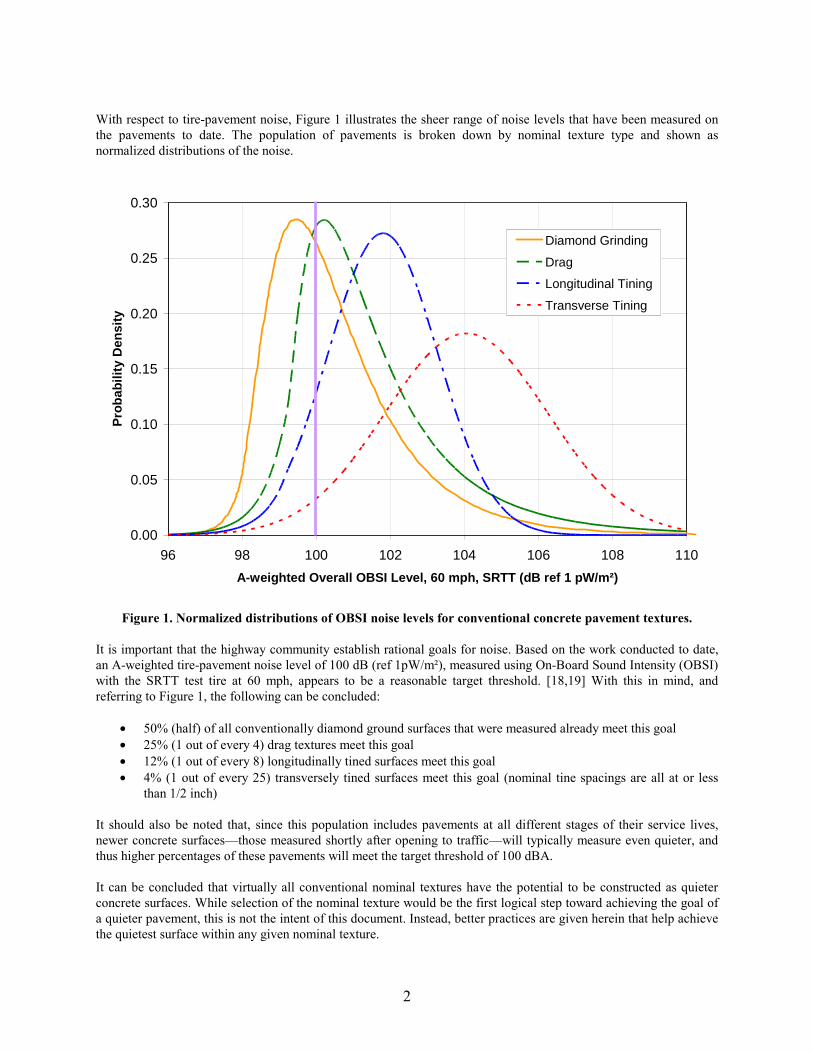
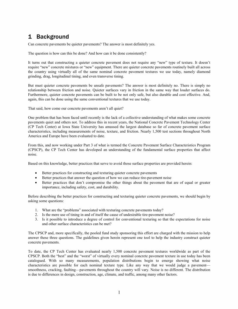
Figure 1. Normalized distributions of OBSI noise levels for conventional concrete pavement textures.
With respect to tire-pavement noise, XFigure 1 X illustrates the sheer range of noise levels that have been measured on the pavements to date. The population of pavements is broken down by nominal texture type and shown as normalized distributions of the noise.
0.00
0.05
0.10
0.15
0.20
0.25
0.30
Pro
bab
ility
Den
sity
Diamond Grinding
Drag
Longitudinal Tining
Transverse Tining
96 98 100 102 104 106 108 110
A-weighted Overall OBSI Level, 60 mph, SRTT (dB ref 1 pW/m²)
It is important that the highway community establish rational goals for noise. Based on the work conducted to date, an A-weighted tire-pavement noise level of 100 dB (ref 1pW/m²), measured using On-Board Sound Intensity (OBSI) with the SRTT test tire at 60 mph, appears to be a reasonable target threshold. [18,19] With this in mind, and referring to Figure 1, the following can be concluded:
X X X X
X X
• 50% (half) of all conventionally diamond ground surfaces that were measured already meet this goal • 25% (1 out of every 4) drag textures meet this goal • 12% (1 out of every 8) longitudinally tined surfaces meet this goal • 4% (1 out of every 25) transversely tined surfaces meet this goal (nominal tine spacings are all at or less
than 1/2 inch)
It should also be noted that, since this population includes pavements at all different stages of their service lives, newer concrete surfaces—those measured shortly after opening to traffic—will typically measure even quieter, and thus higher percentages of these pavements will meet the target threshold of 100 dBA.
It can be concluded that virtually all conventional nominal textures have the potential to be constructed as quieter concrete surfaces. While selection of the nominal texture would be the first logical step toward achieving the goal of a quieter pavement, this is not the intent of this document. Instead, better practices are given herein that help achieve the quietest surface within any given nominal texture.
2

In developing this document, the CP Tech Center draws from its decades of combined experience working for and alongside concrete paving contractors. This document also includes the collective experience of various contractors and equipment manufacturers with a reputation for quality. These guidelines further address the challenges that are faced in consistently producing a high-quality product in a low-bid environment.
This document is intended to serve as interim guidelines and better practices for texturing. Work under the pooled fund study that sponsored the development of this document is ongoing. Additional data is being collected on both existing and new concrete paving projects that will validate the practices described herein. Given the importance of this issue, however, it is believed that many of these practices can be implemented immediately without adverse consequences. Refinements to these practices can then be implemented as necessary as changes to these better practices are made in the near future.
3
2 Summary of Better Practices To build a quieter concrete pavement, one must do the following:
1. Recognize which properties of a pavement surface make it quiet (and which make it loud) 2. Design the pavement surface in such a way as to avoid those adverse properties 3. Construct the pavement surface, too, to avoid those adverse properties, but also in a manner that is both
consistent and cost effective
The first item has been addressed in large part under the CPSCP and through the results of numerous other studies. [19, X20 X, X21] XFigure 2 X summarizes some of the key relationships and can serve as a reference for those seeking to better understand the link from the design and construction to the most relevant as-constructed properties affecting tire-pavement noise.
Concrete Pavement Surface Properties that affect Tire-Pavement Noise
• Surface texture (bumps and dips) o Avoid (flatten) texture that repeats itself at intervals of 1 inch or larger. o Avoid extremely smooth (e.g., floated or polished) surfaces; instead, some fine texture (that is on the scale of 1/8
to 1/4 inch) should be provided. o Texture should be “negatively” oriented, meaning that any “deep” texture should point down (e.g., grooves)
rather than up (e.g., fins). o Striations or “grooves” should, if possible, be oriented in the longitudinal direction, as opposed to the transverse
direction. o If grooves are oriented in the transverse direction, they should be closely spaced and randomized whenever
possible. • Concrete properties
o The mortar (at least, near the surface) should be consistently strong, durable, and wear resistant. Mix design is a key factor, but so are proper placement techniques, including finishing and especially curing.
o Siliceous sands should be used whenever possible in order to improve durability and friction. o For diamond ground pavements, the coarse aggregate in the mixture will constitute the majority of the wearing
surface. Ideally, the aggregate should therefore be hard, durable, and polish resistant in order to maintain the intended texture and thus intended noise level over time.
o For tined textures, there should be an adequate and consistent depth of mortar near the surface to hold the intended geometry.
o Given that there may be conflicting objectives between what is required of the concrete near the surface and what is needed both structurally and for economy, two-lift construction may be a consideration.
• Joints o If joints are present, they can contribute to not only overall noise level, but also annoyance. o Narrow, single-cut joints are preferred over widened (reservoir) cuts. o Faulted joints should be avoided by providing adequate load transfer. o Excess joint sealant should be avoided, especially if it protrudes above pavement surface. o Spalled joints should be prevented through proper design, materials selection, and construction.
Figure 2. Concrete pavement surface properties that affect tire-pavement noise.
Better practices to improve surface properties and thus tire-pavement noise are really about establishing a higher order of control over the texture and other surface properties. It is not about designing or building “innovative” surfaces, but rather the control of conventional texturing techniques. There should be a renewed awareness of the impact that some of the subtle operational characteristics can have on the texture as constructed.
Predictable tire-pavement noise levels are not about how the texture is imparted as much as they are about the recognition and management of the sources of variability. Regarding the concrete, noise levels have to do with the fact that the contractors are imparting texture into a material with inherent variability in both stiffness and plasticity.
4

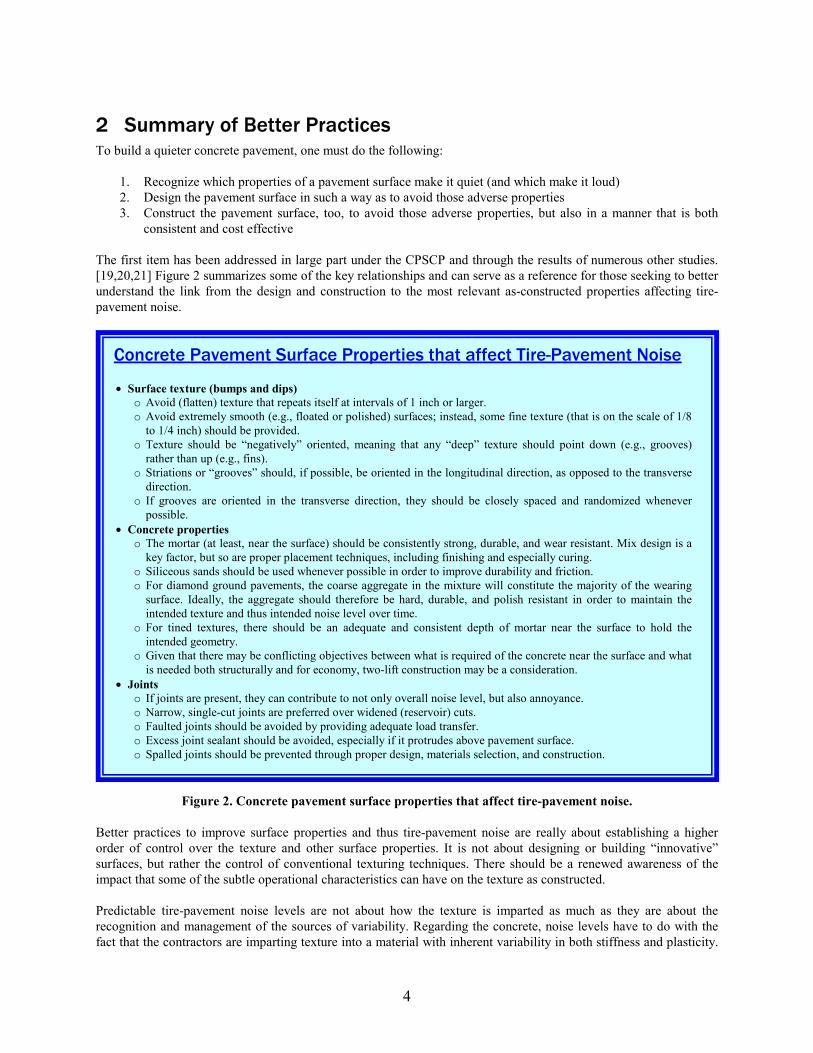
Concrete changes from batch-to-batch, and it changes within a batch. The wind and the sun play a major role, as does the timing of the concrete mixing, transport, placement, and (eventually) the texturing and curing (the latter being important for acoustical durability). Figure 3 summarizes the better practices that will be described in more detail throughout this document. Like Figure 2, this figure can serve as a helpful reference for understanding the numerous issues at play that affect tire-pavement noise. These are, of course, just a few of the better practices that could be adopted if reducing tire-pavement noise is of concern. Many of these, and those listed in more detail herein, are better practices that will also improve smoothness, durability, and, in some cases, reduce costs. For today, we can promote better practices that focus our attention on what we should be doing better on today’s concrete spreads. For tomorrow, the solution will likely be automation of the texturing operation. Over the years, slipform concrete paving operations have become more and more automated. Automatic grade control, for example, is now a virtually standard feature for most slipform pavers. Monitoring vibrator functionality and frequency is also common. Maybe the texturing operation is next. To meet the demands for predictable low-noise surfaces, automation will allow the paver, texture cart, and grinding operators to monitor the texture being produced and to make adjustments on the fly. Ultimately, this approach may be the best way to achieve a specified “target texture” on concrete pavements. For now, we can make significant improvements by simply adopting “better practices.”
5
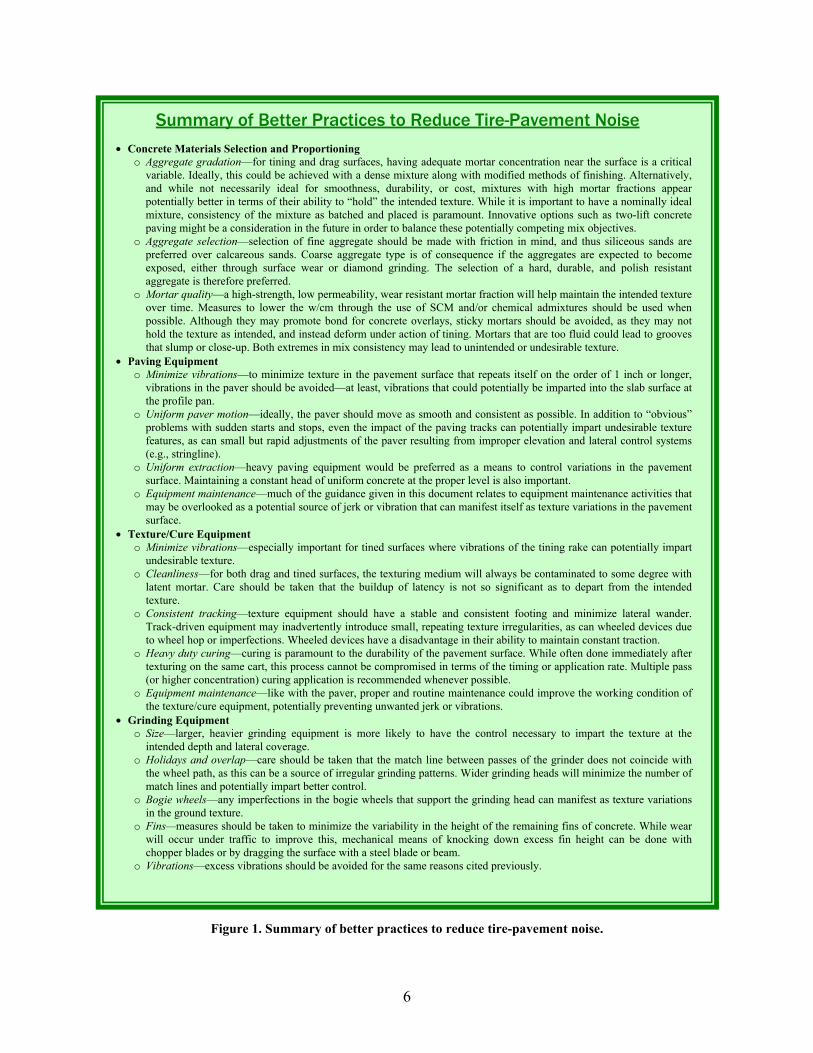
Summary of Better Practices to Reduce Tire-Pavement Noise
• Concrete Materials Selection and Proportioning o Aggregate gradation—for tining and drag surfaces, having adequate mortar concentration near the surface is a critical
variable. Ideally, this could be achieved with a dense mixture along with modified methods of finishing. Alternatively, and while not necessarily ideal for smoothness, durability, or cost, mixtures with high mortar fractions appear potentially better in terms of their ability to “hold” the intended texture. While it is important to have a nominally ideal mixture, consistency of the mixture as batched and placed is paramount. Innovative options such as two-lift concrete paving might be a consideration in the future in order to balance these potentially competing mix objectives.
o Aggregate selection—selection of fine aggregate should be made with friction in mind, and thus siliceous sands are preferred over calcareous sands. Coarse aggregate type is of consequence if the aggregates are expected to become exposed, either through surface wear or diamond grinding. The selection of a hard, durable, and polish resistant aggregate is therefore preferred.
o Mortar quality—a high-strength, low permeability, wear resistant mortar fraction will help maintain the intended texture over time. Measures to lower the w/cm through the use of SCM and/or chemical admixtures should be used when possible. Although they may promote bond for concrete overlays, sticky mortars should be avoided, as they may not hold the texture as intended, and instead deform under action of tining. Mortars that are too fluid could lead to grooves that slump or close-up. Both extremes in mix consistency may lead to unintended or undesirable texture.
• Paving Equipment o Minimize vibrations—to minimize texture in the pavement surface that repeats itself on the order of 1 inch or longer,
vibrations in the paver should be avoided—at least, vibrations that could potentially be imparted into the slab surface at the profile pan.
o Uniform paver motion—ideally, the paver should move as smooth and consistent as possible. In addition to “obvious” problems with sudden starts and stops, even the impact of the paving tracks can potentially impart undesirable texture features, as can small but rapid adjustments of the paver resulting from improper elevation and lateral control systems (e.g., stringline).
o Uniform extraction—heavy paving equipment would be preferred as a means to control variations in the pavement surface. Maintaining a constant head of uniform concrete at the proper level is also important.
o Equipment maintenance—much of the guidance given in this document relates to equipment maintenance activities that may be overlooked as a potential source of jerk or vibration that can manifest itself as texture variations in the pavement surface.
• Texture/Cure Equipment o Minimize vibrations—especially important for tined surfaces where vibrations of the tining rake can potentially impart
undesirable texture. o Cleanliness—for both drag and tined surfaces, the texturing medium will always be contaminated to some degree with
latent mortar. Care should be taken that the buildup of latency is not so significant as to depart from the intended texture.
o Consistent tracking—texture equipment should have a stable and consistent footing and minimize lateral wander. Track-driven equipment may inadvertently introduce small, repeating texture irregularities, as can wheeled devices due to wheel hop or imperfections. Wheeled devices have a disadvantage in their ability to maintain constant traction.
o Heavy duty curing—curing is paramount to the durability of the pavement surface. While often done immediately after texturing on the same cart, this process cannot be compromised in terms of the timing or application rate. Multiple pass (or higher concentration) curing application is recommended whenever possible.
o Equipment maintenance—like with the paver, proper and routine maintenance could improve the working condition of the texture/cure equipment, potentially preventing unwanted jerk or vibrations.
• Grinding Equipment o Size—larger, heavier grinding equipment is more likely to have the control necessary to impart the texture at the
intended depth and lateral coverage. o Holidays and overlap—care should be taken that the match line between passes of the grinder does not coincide with
the wheel path, as this can be a source of irregular grinding patterns. Wider grinding heads will minimize the number of match lines and potentially impart better control.
o Bogie wheels—any imperfections in the bogie wheels that support the grinding head can manifest as texture variations in the ground texture.
o Fins—measures should be taken to minimize the variability in the height of the remaining fins of concrete. While wear will occur under traffic to improve this, mechanical means of knocking down excess fin height can be done with chopper blades or by dragging the surface with a steel blade or beam.
o Vibrations—excess vibrations should be avoided for the same reasons cited previously.
Figure 1. Summary of better practices to reduce tire-pavement noise.
6
3 Overview of Concrete Pavement Texturing
3.1 Texture Classifications By far the most common conventional surface textures for concrete pavements can be categorized as follows:
1. Tined textures a. Transverse
i. Uniformly spaced ii. Randomly spaced
b. Longitudinal (uniformly spaced)
2. Drag textures a. Artificial turf b. Burlap c. Broom
3. Diamond grinding (for both new concrete pavement surfaces and for surface restoration)
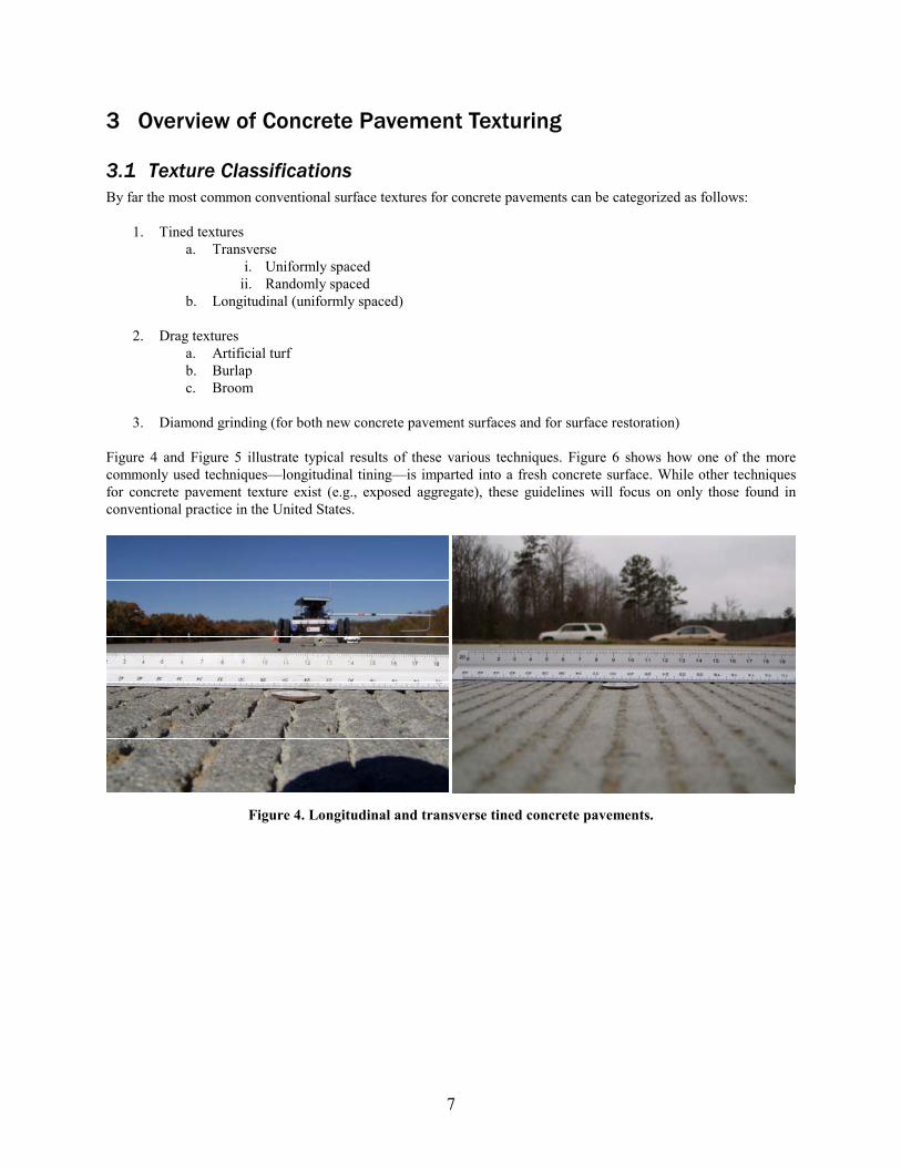
XFigure 4 X and XFigure 5 X illustrate typical results of these various techniques. XFigure 6 X shows how one of the more commonly used techniques—longitudinal tining—is imparted into a fresh concrete surface. While other techniques for concrete pavement texture exist (e.g., exposed aggregate), these guidelines will focus on only those found in conventional practice in the United States.
Figure 4. Longitudinal and transverse tined concrete pavements.
7
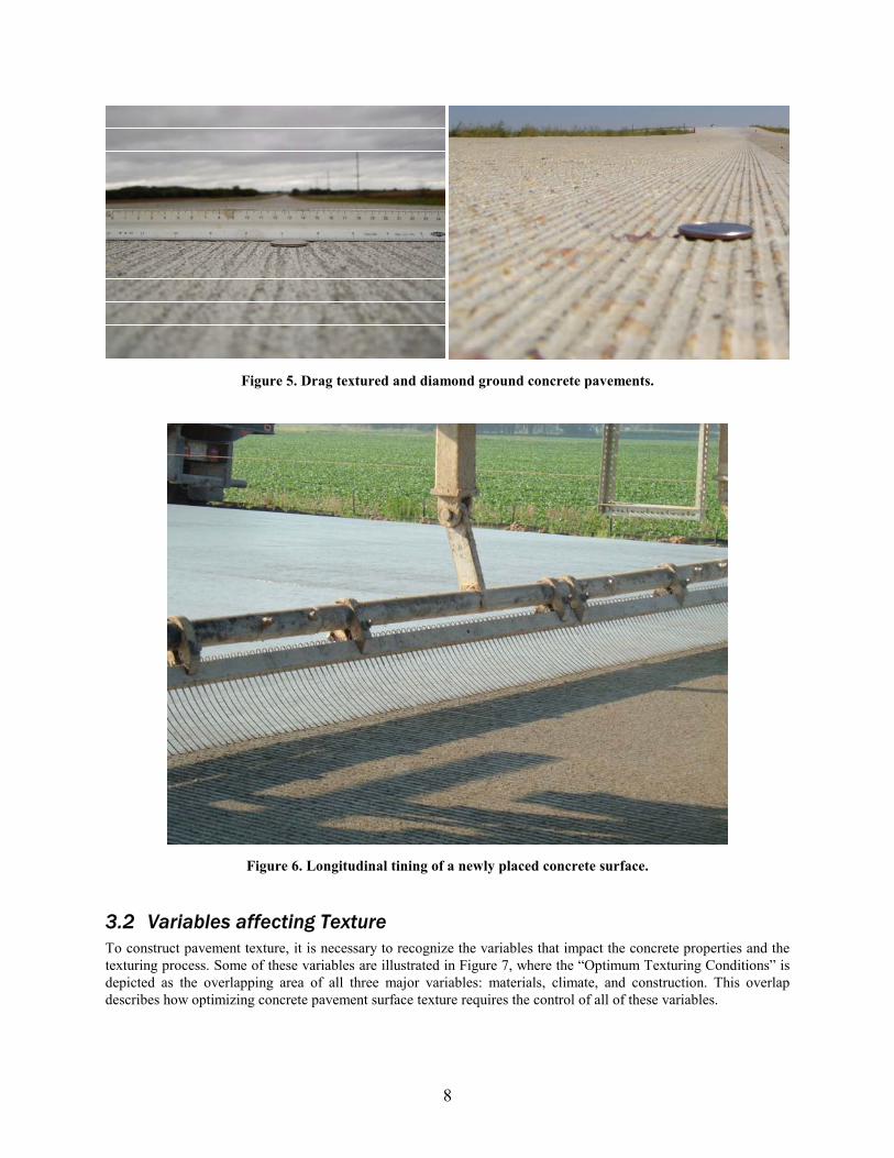
Figure 5. Drag textured and diamond ground concrete pavements.
Figure 6. Longitudinal tining of a newly placed concrete surface.
3.2 Variables affecting Texture To construct pavement texture, it is necessary to recognize the variables that impact the concrete properties and the texturing process. Some of these variables are illustrated in XFigure 7 X, where the “Optimum Texturing Conditions” is depicted as the overlapping area of all three major variables: materials, climate, and construction. This overlap describes how optimizing concrete pavement surface texture requires the control of all of these variables.
8
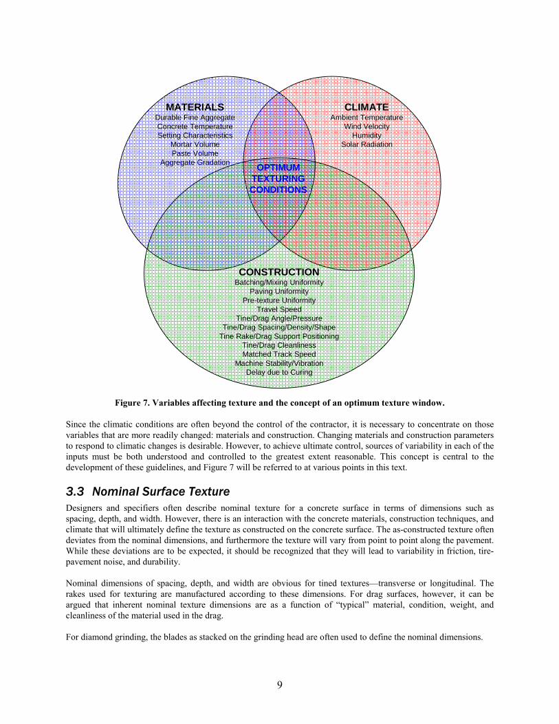
Figure 7. Variables affecting texture and the concept of an optimum texture window.
MATERIALS Durable Fine Aggregate Concrete Temperature Setting Characteristics
Mortar Volume Paste Volume
Aggregate Gradation
CLIMATE Ambient Temperature
Wind Velocity Humidity
Solar Radiation
CONSTRUCTION Batching/Mixing Uniformity
Paving Uniformity Pre-texture Uniformity
Travel Speed Tine/Drag Angle/Pressure
Tine/Drag Spacing/Density/Shape Tine Rake/Drag Support Positioning
Tine/Drag Cleanliness Matched Track Speed
Machine Stability/Vibration Delay due to Curing
OPTIMUM TEXTURING CONDITIONS
Since the climatic conditions are often beyond the control of the contractor, it is necessary to concentrate on those variables that are more readily changed: materials and construction. Changing materials and construction parameters to respond to climatic changes is desirable. However, to achieve ultimate control, sources of variability in each of the inputs must be both understood and controlled to the greatest extent reasonable. This concept is central to the development of these guidelines, and XFigure 7 X will be referred to at various points in this text.
3.3 Nominal Surface Texture Designers and specifiers often describe nominal texture for a concrete surface in terms of dimensions such as spacing, depth, and width. However, there is an interaction with the concrete materials, construction techniques, and climate that will ultimately define the texture as constructed on the concrete surface. The as-constructed texture often deviates from the nominal dimensions, and furthermore the texture will vary from point to point along the pavement. While these deviations are to be expected, it should be recognized that they will lead to variability in friction, tire-pavement noise, and durability.
Nominal dimensions of spacing, depth, and width are obvious for tined textures—transverse or longitudinal. The rakes used for texturing are manufactured according to these dimensions. For drag surfaces, however, it can be argued that inherent nominal texture dimensions are as a function of “typical” material, condition, weight, and cleanliness of the material used in the drag.
For diamond grinding, the blades as stacked on the grinding head are often used to define the nominal dimensions.
9
3.4 Texture Measurement The most common method of characterizing texture is depth using the volumetric or “sand” patch test. [ X13 X] This test is simple to perform, but it has many drawbacks as a process control procedure. For example, it can only be performed on a hardened pavement surface. In addition, only a very small area of the pavement is measured by each test, and the test relies on the technician’s judgment to determine if the volume of material (sand or, more typically, glass beads) is uniformly spread.
As an alternative, some practitioners employ quick measurements to check the texture depth during construction. These are often done with a coin, tire tread gauge, or other graduated device that fits inside of the groove left by the tine. Obviously, these techniques prove difficult or impossible on drag or diamond ground surfaces. They are also— like the sand patch—small samples that may or may not be representative of the entire pavement surface. And, again, these techniques are difficult to perform on fresh concrete surfaces.
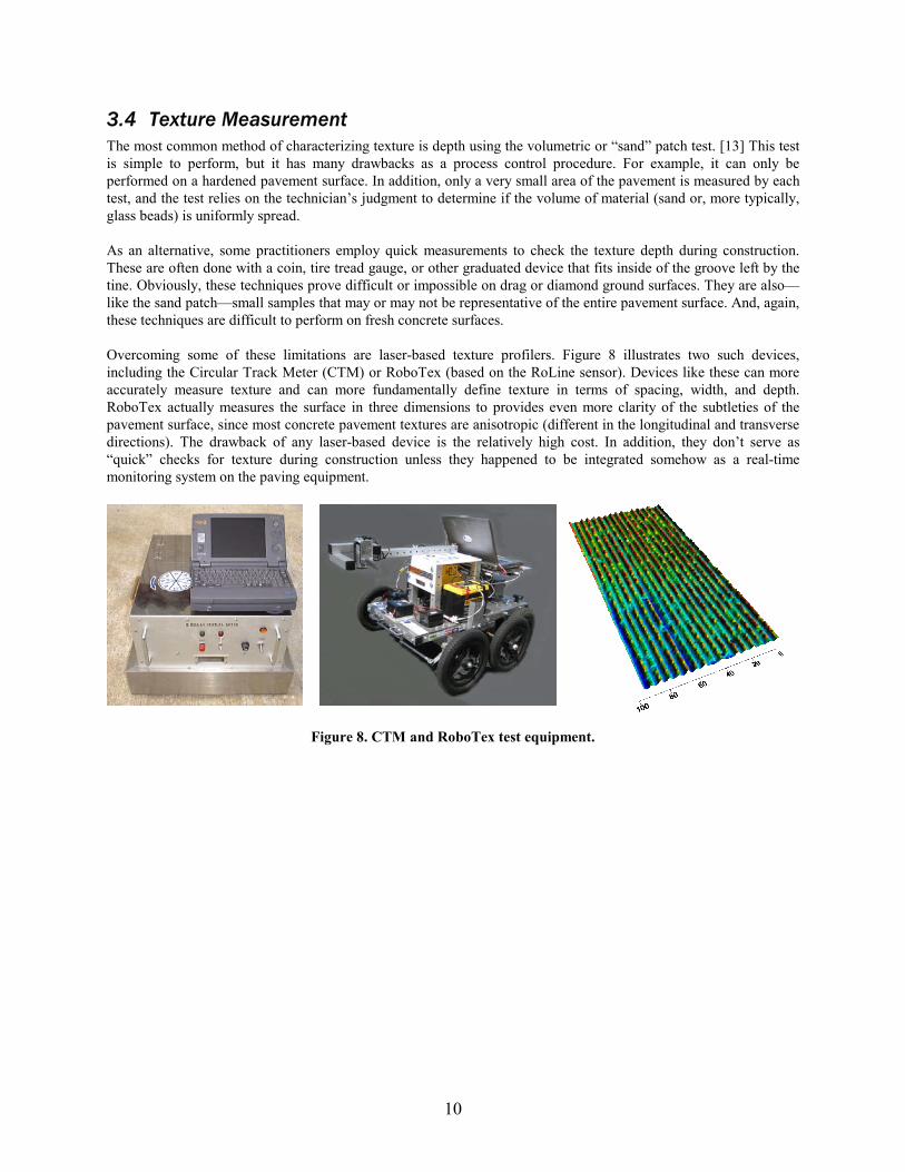
Overcoming some of these limitations are laser-based texture profilers. XFigure 8 X illustrates two such devices, including the Circular Track Meter (CTM) or RoboTex (based on the RoLine sensor). Devices like these can more accurately measure texture and can more fundamentally define texture in terms of spacing, width, and depth. RoboTex actually measures the surface in three dimensions to provides even more clarity of the subtleties of the pavement surface, since most concrete pavement textures are anisotropic (different in the longitudinal and transverse directions). The drawback of any laser-based device is the relatively high cost. In addition, they don’t serve as “quick” checks for texture during construction unless they happened to be integrated somehow as a real-time monitoring system on the paving equipment.
Figure 8. CTM and RoboTex test equipment.
10
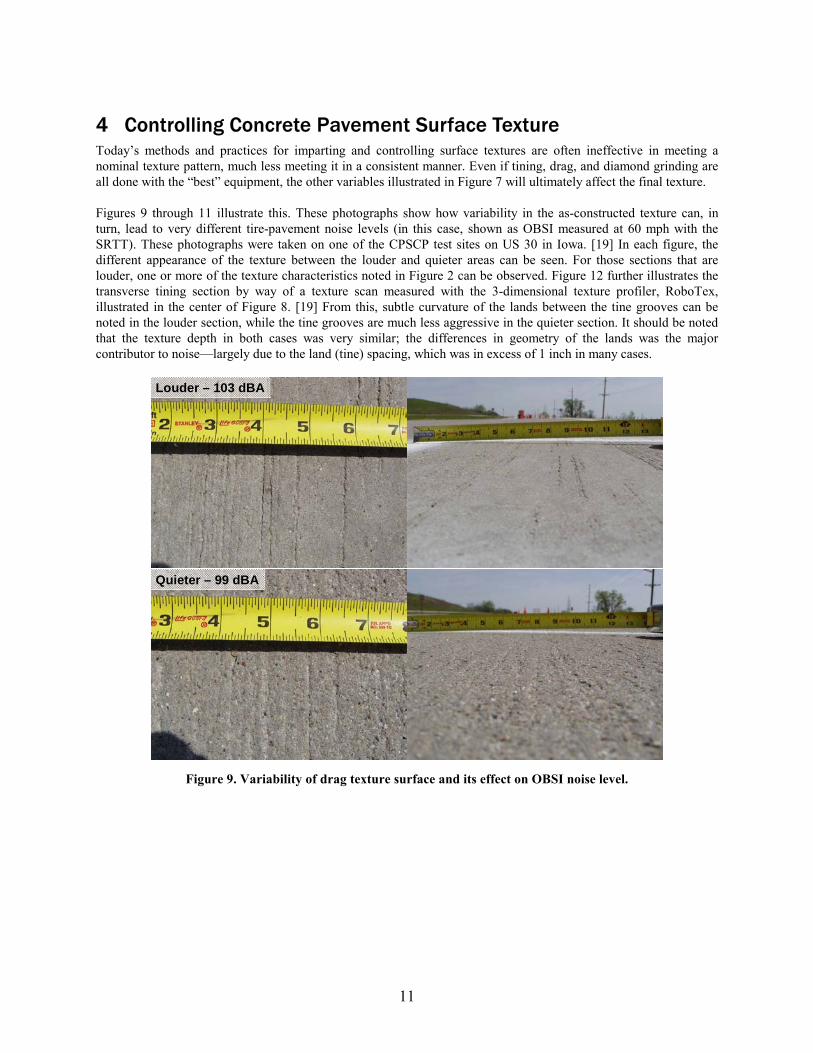
4 Controlling Concrete Pavement Surface Texture Today’s methods and practices for imparting and controlling surface textures are often ineffective in meeting a nominal texture pattern, much less meeting it in a consistent manner. Even if tining, drag, and diamond grinding are all done with the “best” equipment, the other variables illustrated in XFigure 7 X will ultimately affect the final texture.
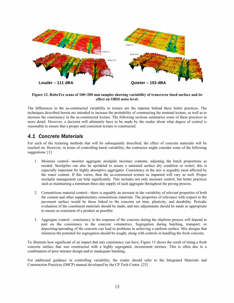
XFigures 9 X through 11 11X illustrate this. These photographs show how variability in the as-constructed texture can, in turn, lead to very different tire-pavement noise levels (in this case, shown as OBSI measured at 60 mph with the SRTT). These photographs were taken on one of the CPSCP test sites on US 30 in Iowa. [19 X] In each figure, the different appearance of the texture between the louder and quieter areas can be seen. For those sections that are louder, one or more of the texture characteristics noted in XFigure 2 X can be observed. XFigure 12 X further illustrates the transverse tining section by way of a texture scan measured with the 3-dimensional texture profiler, RoboTex, illustrated in the center of XFigure 8. [ X19] From this, subtle curvature of the lands between the tine grooves can be noted in the louder section, while the tine grooves are much less aggressive in the quieter section. It should be noted that the texture depth in both cases was very similar; the differences in geometry of the lands was the major contributor to noise—largely due to the land (tine) spacing, which was in excess of 1 inch in many cases.
Louder – 103 dBA
Quieter – 99 dBA
Figure 9. Variability of drag texture surface and its effect on OBSI noise level.
11
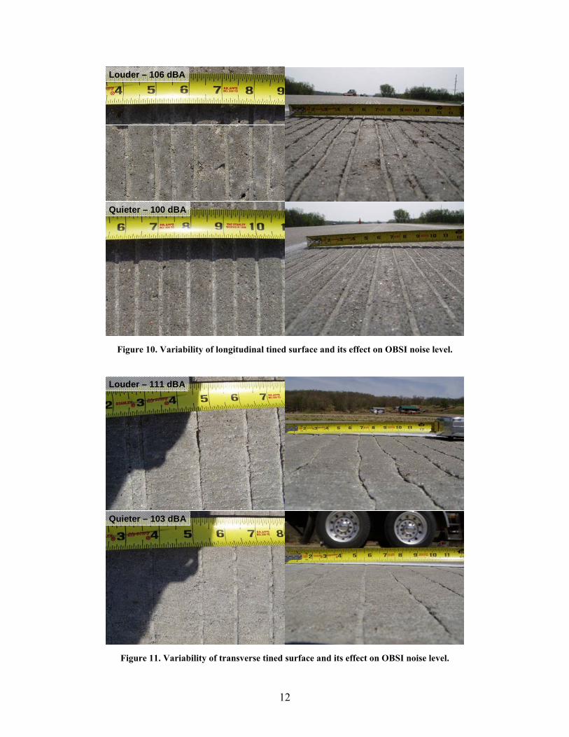
Louder – 106 dBA
Quieter – 100 dBA
Figure 10. Variability of longitudinal tined surface and its effect on OBSI noise level.
Louder – 111 dBA
Quieter – 103 dBA
Figure 11. Variability of transverse tined surface and its effect on OBSI noise level.
12
Scale 1:1
Scale 10:1
Scale 1:1
Scale 10:1
Louder – 111 dBA Quieter – 103 dBA
Figure 12. RoboTex scans of 100×200 mm samples showing variability of transverse tined surface and its effect on OBSI noise level.
The differences in the as-constructed variability in texture are the impetus behind these better practices. The techniques described herein are intended to increase the probability of constructing the nominal texture, as well as to increase the consistency in the as-constructed texture. The following sections summarize some of these practices in more detail. However, a decision will ultimately have to be made by the reader about what degree of control is reasonable to ensure that a proper and consistent texture is constructed.
4.1 Concrete Materials For each of the texturing methods that will be subsequently described, the effect of concrete materials will be touched on. However, in terms of controlling batch variability, the contractor might consider some of the following suggestions: [ X1 X]
1. Moisture control—monitor aggregate stockpile moisture contents, adjusting the batch proportions as needed. Stockpiles can also be sprinkled to assure a saturated surface dry condition or wetter; this is especially important for highly absorptive aggregates. Consistency in the mix is arguably most affected by the water content. If this varies, then the as-constructed texture as imparted will vary as well. Proper stockpile management can help significantly. This includes not only moisture control, but better practices such as maintaining a minimum three-day supply of each aggregate throughout the paving process.
2. Cementitious material control—there is arguably an increase in the variability of relevant properties of both the cement and other supplementary cementitious materials. The properties of relevance with respect to the pavement surface would be those linked to the concrete set time, plasticity, and durability. Periodic evaluation of the constituent materials should be made, and mix adjustments should be made as appropriate to ensure as consistent of a product as possible.
3. Aggregate control—consistency in the response of the concrete during the slipform process will depend in part on the consistency in the concrete volumetrics. Segregation during batching, transport, or depositing/spreading of the concrete can lead to problems in achieving a uniform surface. Mix designs that minimize the potential for segregation should be sought, along with controls in handling the fresh concrete.
To illustrate how significant of an impact that mix consistency can have, XFigure 13 shows the result of tining a fresh concrete surface that was constructed with a highly segregated, inconsistent mixture. This is often due to a combination of poor mixture design and/or inadequate batching.
For additional guidance in controlling variability, the reader should refer to the Integrated Materials and Construction Practices (IMCP) manual developed by the CP Tech Center. [ X23]
13
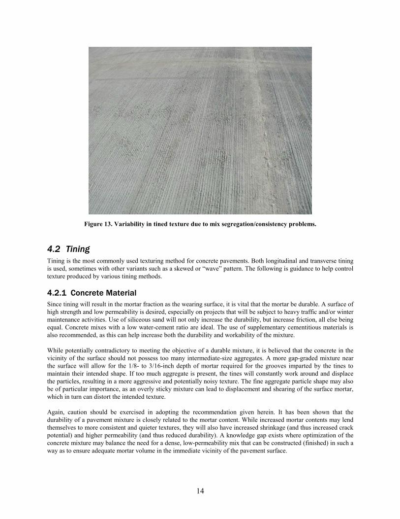
Figure 13. Variability in tined texture due to mix segregation/consistency problems.
4.2 Tining Tining is the most commonly used texturing method for concrete pavements. Both longitudinal and transverse tining is used, sometimes with other variants such as a skewed or “wave” pattern. The following is guidance to help control texture produced by various tining methods.
4.2.1 Concrete Material Since tining will result in the mortar fraction as the wearing surface, it is vital that the mortar be durable. A surface of high strength and low permeability is desired, especially on projects that will be subject to heavy traffic and/or winter maintenance activities. Use of siliceous sand will not only increase the durability, but increase friction, all else being equal. Concrete mixes with a low water-cement ratio are ideal. The use of supplementary cementitious materials is also recommended, as this can help increase both the durability and workability of the mixture.
While potentially contradictory to meeting the objective of a durable mixture, it is believed that the concrete in the vicinity of the surface should not possess too many intermediate-size aggregates. A more gap-graded mixture near the surface will allow for the 1/8- to 3/16-inch depth of mortar required for the grooves imparted by the tines to maintain their intended shape. If too much aggregate is present, the tines will constantly work around and displace the particles, resulting in a more aggressive and potentially noisy texture. The fine aggregate particle shape may also be of particular importance, as an overly sticky mixture can lead to displacement and shearing of the surface mortar, which in turn can distort the intended texture.
Again, caution should be exercised in adopting the recommendation given herein. It has been shown that the durability of a pavement mixture is closely related to the mortar content. While increased mortar contents may lend themselves to more consistent and quieter textures, they will also have increased shrinkage (and thus increased crack potential) and higher permeability (and thus reduced durability). A knowledge gap exists where optimization of the concrete mixture may balance the need for a dense, low-permeability mix that can be constructed (finished) in such a way as to ensure adequate mortar volume in the immediate vicinity of the pavement surface.
14

On the other extreme, too much fluidity in the mortar can also prove problematic, as the tined grooves will tend to “slump,” and, in the worst case, close off pockets being created. To avoid this, the sand type and gradation should be selected for stability in terms of flow under low to moderate levels of vibration.
Finally, segregation of the mixture should be avoided, since not only will the tining process respond differently to concrete of varying volumetrics, but also the wear of a concrete surface will be nonuniform, eventually leading to a “modulation” in the noise level and/or frequency characteristics that can prove annoying to vehicle occupants.
4.2.2 Equipment Little is known about the particular aspects of paving and texture equipment as they affect the as-constructed texture. Given that variability is undesirable, an automated texture/cure cart with uniform depth and alignment would be recommended. When transverse tining is used, this control should be present along the tining rake to prevent one end of the rake from imparting texture different from the other.
Vibrations of various sorts at both the paver and tining rake should also be avoided. Section X5 X of these guidelines includes very specific guidance on how this might be accomplished through an elevated awareness of the equipment operation and maintenance.
In addition to minimizing vibrations, any alterations to the equipment that will minimize the variability of the concrete that is displaced might be preferred. It should be remembered that the concrete that is displaced by the tines will simply redeposit somewhere on the pavement surface. In many circumstances, these “random” deposits will contribute to additional noise being generated. While such equipment modifications are not readily known, this guidance should serve as a target for innovation.
While these guidelines do not serve to recommend texture type or geometry per se, it is known that when transverse tining is used, small (1/2 inch or less) spacings will most often result in the quietest surfaces. Adding some degree of randomness to this spacing will further minimize annoying “tones” that may develop when driving this pavement.
4.2.3 Construction Technique A quiet concrete surface is not one that is completely smooth. Some (smaller) texture is necessary to minimize the noise that is generated. Pre-texturing the pavement with a drag texture prior to tining is therefore important. A heavy drag surface is recommended, with specific recommendations on techniques found in Section X4.3 X.
Since the durability of the mortar at the surface is so critical to the success of a tined surface, excellent curing techniques become mandatory. The use of multiple applications of conventional curing compound or, in more extreme circumstances, wet curing techniques should be considered for those projects where noise is a particular concern. The timing of the curing application is also important, with the recommendation that it be applied as soon as possible after placement (and texturing).
In terms of constructability, longitudinal tining tends to produce more consistent surfaces than transverse tining. The continuous process of longitudinal tining allows both the texturing and curing to be applied more consistently than during the “start and stop” motion inherent in transverse tining. Furthermore, the advantages of a single texture-cure machine can be realized during longitudinal tining, which in and of itself leads to greater consistency than when two machines perform these operations independently.
4.2.4 Spacing On tined surfaces, texture spacing is controlled by ensuring that the individual tines are spaced to meet the specification. This step is mandatory when ordering the rake from the manufacturer, at the beginning of paving, and each time that the texturing equipment is transported on a project. Tines are often bent or damaged during transport. The spacing of tines should be checked frequently to identify missing, bent, and misaligned tines.
15
4.2.5 Width The width of the tined groove is a function of the tine width dimension. Depending on the concrete mix properties, there may be some change in the width of the groove immediately after tining. Plastic (fluid) concrete can close back together after tining, for example. This can be altered by increasing the hydration time before tining or through mix adjustments.
Alternatively, an increase in the groove width can result from a buildup of dried concrete paste on the tine. This can be remedied by cleaning the tines periodically. A broomstick or similar object can be dragged across the bottom of the tines regularly to break loose concrete paste that is clinging to the tines. It is much easier to clean the tines regularly before the cement paste is hardened than it is to replace tines because the cement paste is too hard to remove.
Finally, worn tines should be replaced as soon as practical when the nominal tine dimension is believed to be critical. Worn tines will result in rounded edges that may differ from those that are specified.
4.2.6 Depth Tine depth is arguably the most difficult variable to control. It is a function of the following variables:
• Quantity and size of aggregates near the concrete surface that are dislodged by the tines • Density (stiffness), workability, and combined gradation of the concrete mixture near the surface of the
pavement • Overall mix uniformity • Downward force applied to the tine • Surface area of the tine in contact with the concrete—affected by the tine dimension and the angle of the
tine with respect to the pavement
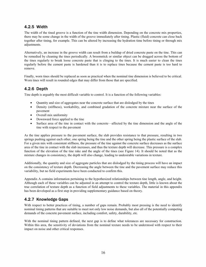
As the tine applies pressure to the pavement surface, the slab provides resistance to that pressure, resulting in two springs pushing against each other, one spring being the tine and the other spring being the plastic surface of the slab. For a given mix with consistent stiffness, the pressure of the tine against the concrete surface decreases as the surface area of the tine in contact with the slab increases, and thus the texture depth will decrease. This pressure is a complex function of the elevation of the tine rake and the angle of the tines (see XFigure 14 X). It should be noted that as the mixture changes in consistency, the depth will also change, leading to undesirable variations in texture.
Additionally, the quantity and size of aggregate particles that are dislodged by the tining process will have an impact on the consistency of texture depth. Decreasing the angle between the tine and the pavement surface may reduce this variability, but no field experiments have been conducted to confirm this.
Appendix A contains information pertaining to the hypothesized relationships between tine length, angle, and height. Although each of these variables can be adjusted in an attempt to control the texture depth, little is known about the true correlation of texture depth as a function of field adjustments to these variables. The material in this appendix has been developed as a first step in providing supplementary guidance based on theory.
4.2.7 Knowledge Gaps With respect to better practices of tining, a number of gaps remain. Probably most pressing is the need to identify nominal tining patterns that are suitable to meet not only low noise demands, but also all of the potentially competing demands of the concrete pavement surface, including comfort, safety, durability, etc.
With the nominal tining pattern defined, the next gap is to define what tolerances are necessary for construction. Within this area, the sensitivity of deviations from the nominal texture needs to be understood with respect to their impact on noise and other critical responses.
16
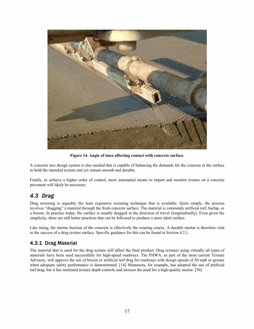
Figure 14. Angle of tines affecting contact with concrete surface.
A concrete mix design system is also needed that is capable of balancing the demands for the concrete at the surface to hold the intended texture and yet remain smooth and durable.
Finally, to achieve a higher order of control, more automated means to impart and monitor texture on a concrete pavement will likely be necessary.
4.3 Drag Drag texturing is arguably the least expensive texturing technique that is available. Quite simply, the process involves “dragging” a material through the fresh concrete surface. The material is commonly artificial turf, burlap, or a broom. In practice today, the surface is usually dragged in the direction of travel (longitudinally). Even given the simplicity, there are still better practices that can be followed to produce a more ideal surface.
Like tining, the mortar fraction of the concrete is effectively the wearing course. A durable mortar is therefore vital to the success of a drag texture surface. Specific guidance for this can be found in Section X4.2.1 X.
4.3.1 Drag Material The material that is used for the drag texture will affect the final product. Drag textures using virtually all types of materials have been used successfully for high-speed roadways. The FHWA, as part of the most current Texture Advisory, will approve the use of broom or artificial turf drag for roadways with design speeds of 50 mph or greater when adequate safety performance is demonstrated. [ X14] Minnesota, for example, has adopted the use of artificial turf drag, but it has instituted texture depth controls and stresses the need for a high-quality mortar. [X30]
17
4.3.2 Construction Technique Like with tining, better practices for curing are critical to the success of drag textures. Vibrations of the paver and, in this case, the bridge supporting the drag material should be minimized. More on these can be found in Sections X4.2.2 X
and X4.2.3 X.
The geometry, weight, saturation, and conditioning of the drag material are all important too, however. In general, drag surfaces that are more “aggressive” (deep) will not only produce lower noise, but will maintain the lower noise levels for a longer period of time as more wear of the surface occurs. The length of the drag material that is in contact with the fresh concrete should be a minimum of 6 feet. When burlap is used, the material should be heavy (AASHTO M 182, Class 3 or 4). [ X15] Burlap should also remain visibly damp during the drag process and be frayed along the trailing edge for a length of at least 1 inch. If performed successfully, the burlap will produce deep striations like that illustrated in XFigure 15 X.
Figure 15. Deep striations from burlap drag used on an Autobahn highway in Germany.
To maintain a consistent surface, the drag process should proceed at the same rate as the paving process and with minimal time between these operations. The most logical means to do this is to have the bridge with the drag material towed by the paver, with additional emphasis that the paver should advance at a consistent rate.
All drag materials will collect mortar and paste because of the texturing process. Most of this material will be continually redeposited. However, depending on the specific mix and other variables (see XFigure 7 X), the drag material may eventually collect so much mortar/paste that it loses its effectiveness to produce a surface with deep striations. At this point, the material should be replaced and/or cleaned to restore the intended function. At a minimum, the material should be thoroughly washed and/or replaced at the end of a day’s paving.
4.3.3 Knowledge Gaps The need for an improved concrete mix design process that was identified in Section X4.2.7 X also applies for drag surfaces. In addition, a need exists to identify the sensitivity of the various drag materials and conditioning in terms of their impact on the as-constructed texture.
18
4.4 Diamond Grinding
Diamond grinding is a texturing technique that can be used for both newly placed concrete as well as for rehabilitating existing concrete pavements. The process involves removing the surface of the concrete via a gang-mounted spindle of saw blades (and spacers). The resulting “corduroy” surfaces are among the quietest concrete pavement surfaces that can be constructed. However, not all diamond grinding projects are quiet, and one of the shortcomings of the technique is misapplication on projects (concretes) that wear quickly.
4.4.1 Project Selection
Unlike conventional “wet” textures such as tining and drag, diamond grinding will result in a surface that largely consists of the coarse aggregates in the concrete mixture. As a result, the need for a durable, polish-resistant coarse aggregate is vital to the success of this technique in providing a long-life surface. Candidate projects should be selected that meet these minimum aggregate requirements and/or have the potential for the surface to wear quickly. Of particular relevance to noise is the homogeneity (or lack thereof) of the aggregate. Coarse aggregates that are of the same type (e.g., limestone, granite) will tend to wear in the same manner, in contrast to aggregates that are blends of numerous types (e.g., “river rock”). The latter will result in uneven wear that can introduce additional noise over time.
4.4.2 Grinding Head
Even the most subtle details of the grinding head used will affect the as-constructed texture. On the head, blades and spacers of various size and type are traditionally selected in such a way as to ensure that the target functional standard (e.g., smoothness) is achieved while further considering the potential for wear (of both the grinding head and of the pavement under traffic). From what is known today, there is no “magic” combination of blades and spacers that will achieve the quietest surface. A number of aspects of the final texture will affect the noise characteristics and the durability of the surface. The “fins” left behind between the sawed grooves, for example, are known to introduce noise if they are not uniform in height (as is often the case). Ongoing work by the ACPA is investigating the use of “chopper” blades in lieu of spacers to even the tops of the fins in order to reduce noise.
4.4.3 Equipment Operation Section 5.3 of these guidelines identifies some specific operations and maintenance activities that may warrant renewed diligence if noise is a concern. In addition to this, however, significant improvements to control the texturing operation may involve real-time sensing of the as-ground surface. This would provide operators with the information that may allow them to adjust forward speed, power, or other operational characteristics that could reduce unwanted texture features that may contribute to noise.
4.4.4 Knowledge Gaps
Since the durability of the coarse aggregate is critical to the longevity of a diamond ground surface, additional work needs to be done to classify aggregates in terms of their ability to hold texture. While surrogate tests for wear are used today, little has been done to even correlate these results to the performance of diamond ground surfaces. In addition to traffic wear, additional consideration might be given to the effect of winter maintenance activities on the durability of ground surfaces. A better understanding of the operation and maintenance of a diamond grinder is also necessary. It would be advisable for standard operating procedures to be documented rather than relying exclusively on “on the job”
19
20
training. In the future, clearer links between the changes in operating characteristics of the equipment and the resulting texture should also be better documented. Finally, while evidence exists that no nominal grinding pattern is quieter, the pattern is known to affect wear rate, and therefore a need exists to optimize the pattern as a function of the project-specific conditions (especially the concrete type). Tolerances on these dimensions should also be investigated in terms of their sensitivity to the resulting noise, other surface characteristics, and durability.
4.5 Making Field Adjustments Prior to construction, adjustments in the field to control texture can be accomplished in the following steps:
• Verify that the equipment and materials being used are set up to target the nominal texture that will meet the project specifications.
• For tining, verify that the tine width meets project specifications. Furthermore, use the appropriate tine length for expected conditions. Use shorter tines for hot dry weather, firm pavement surface, and deeper texture; use longer tines for cool damp weather, soft pavement surface, and shallower texture.
• For grinding, verify that the correct grinding head is being used for the concrete being textured. • As appropriate, set the crown and/or cross-slope of the texture equipment to match the pavement cross-
section. The tips of the tines should be parallel to the proposed pavement surface. The supports for drag textures should also be at equal heights from the pavement surface across the width.
Recognize that some adjustments to texturing equipment cannot be readily done “on the fly.” Because consistent surface texturing is time dependent, any changes that are made must be done using the parameters under the control of the operator. Changing the tine length or grinding head, for example, cannot be practically done. However, depending on the equipment, it may be possible to adjust the tine angle or grinding pressure in a timely manner without adversely affecting the efficiency of the overall operation.
4.6 Other Considerations
4.6.1 Steering and Elevation Controls Controlling the steering of the texture machine off of the stringline used for paving is a suggested method for improving the uniformity of a pavement surface texture. Utilizing automated elevation control for longitudinal texturing is not mandatory, but it is highly recommended. If automatic elevation controls are used, the speed of the machine should be kept within a limit that allows the hydraulic system being used to react as intended. A smooth track line for the texture machine is mandatory to reduce the variability of the texture. Since variability in the texture is a characteristic that should be avoided, it is recommended that equipment be sought that possesses a rigid frame capable of transmitting steering forces from one end to the other, along with a quality propulsion and steering system. The combination of these will increase the probability that the texture-cure machine will steer accurately, resulting in a more uniform texture. In other words, a texture-cure machine being used for longitudinal tining that does not steer accurately will result in “wavy” longitudinal grooves that can contribute to the overall noise level of that surface.
4.6.2 Crown and Cross-Slope Changes Many pavements have variations in the typical section due to super-elevated curves, matching existing pavement cross-slopes, etc. These cross-section changes must be accounted for in the surface texturing process. For non-crowned pavements, controlling the elevation of the texture machine with the paving stringline should keep the texture rake or drag supports parallel to the width of the slab surface. When the cross-section of a crowned pavement changes (for example when transitioning between tangents and curves), some texture-cure machines, because of their design, must sometimes be manually adjusted to match the
pavement cross-section. This is sometimes the case even if automatic elevation controls are being used. Suggested methods for cross-section adjustments are listed below:
• Transverse texturing o Each time the texture machine is advanced to make the next transverse texturing pass, verify that the
texture machine frame is parallel to the pavement cross-section for the full width of the pavement. Since the tine rake travels across the pavement in a carriage that is attached to the machine frame, the crown adjustment in the frame will need to be adjusted for cross-section changes. One simple way to check the frame’s crown relative to the pavement is to possibly hang four plum bobs from the frame on equal-length strings (two on either side of the crown point and two near the pavement edges). A visual check will reveal if the frame is parallel to the pavement surface, or both sides of the machine may be lowered until all four plum bobs are in contact with the pavement at the same time and then raised in unison to maintain a parallel plane. Some texture machines may optionally include or be adapted to have automatic sensors that assist in this process.
• Longitudinal Texturing o Longitudinal texturing is similar to transverse in the way that cross-section changes are made at
stop/start points. Plumb bobs or sensors are not necessary, since the tips of the tines or position of the drag material provide a visual reference across the width of the pavement. Additionally, the crown adjustment of the texture machine may need to be adjusted simultaneously with the texturing process. The degree of this “on-the-go” adjustment will depend on the length of pavement being textured and the rate of pavement cross-slope change. For example, if the texture machine operator is texturing and curing the pavement in 100-foot increments, the outside edge of the pavement could rotate up approximately 2 inches in a 100-foot segment of a super-elevation transition. This degree of change would require a crown adjustment while texturing. This adjustment is completely operator-dependent, and at this time no automatic controls are available for texturing equipment.
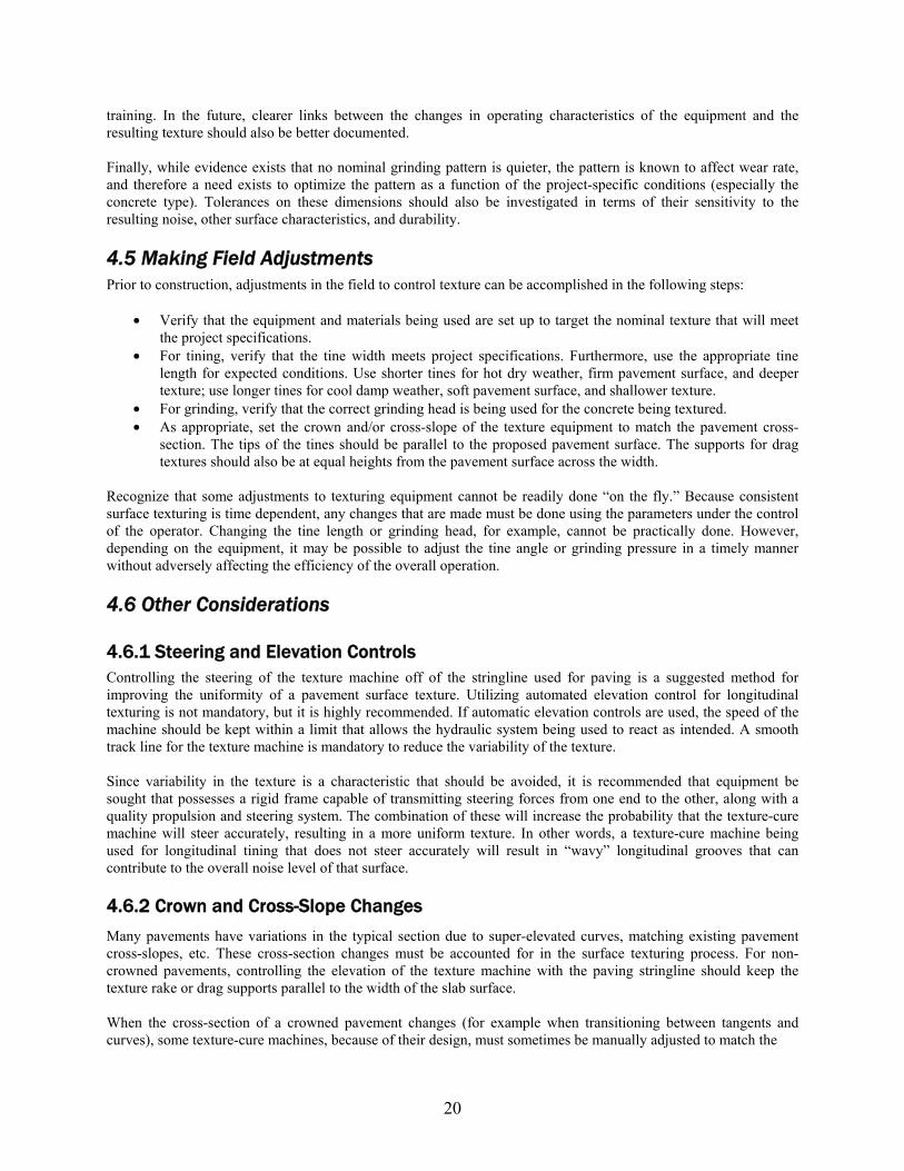
• Cross-section changes should be visibly marked with signs on the project so that the texture machine operator is aware of the location and rate of cross-slope changes. These types of changes are illustrated in XFigure 16.
tine rake profile/plumb bob reference roadway surface
normal crown super-elevation transition
full super-elevation
Figure 16. Pavement cross-slope adjustments.
To overcome some of the inherent limitations of manual elevation adjustments, it is recommended that automated controls be used whenever possible. Sensors that can gauge the cross-section of the pavement section are particularly useful and will increase the quality as a result. These sensors can include a combination of stringline and height (e.g., sonic) sensors located at strategic points across the width of the pavement.
4.6.3 Workmanship and Ownership Constructing more uniform surface texture will require equipment operators that are properly trained and skilled in their craft. It will also require a change in some management philosophies to emphasize the importance of having the same operator day-in and day-out to improve texture consistency.
Traditionally, texture-cure equipment has been deemed less important than other equipment, such as a slipform paver. In response to more stringent specifications and new incentives for thickness and smoothness, many contractors have chosen to upgrade their pavers. However, since the as-constructed texture is often overlooked in inspection, much less considered a pay item, there is much less incentive to invest in higher quality equipment.
21
4.6.4 Texturing Speed Normal ground speed for longitudinal texturing is typically on the order of 25 to 75 feet per minute. Since the texturing process proceeds faster than the paving process (which is typically 5 to 10 feet per minute), it is not necessary to texture at a high speed. The operator should find an operating speed that minimizes machine vibrations and/or oscillations that can possibly be transmitted to the pavement surface. On some equipment, excessively slow speeds can result in “crab-walking” of the texture machine, which results in inaccurate steering. This can be problematic in terms of introducing unwanted texture variability. Ideally, the texture speed should be set so the machine can steer accurately; it should advance in such a way as to maintain alignment with the stringline, as well as to minimize unwanted vibrations.
The speed of transverse texturing across the width of the slab has been observed to be on the order of 30 feet per minute. As with longitudinal texturing, equipment vibration and oscillation transferred to the pavement surface is one concern with determining the optimum speed for transverse texturing. The texture equipment should be set-up and maintained in a condition that will result in a consistently smooth operation of lowering the texturing medium, pulling it across the width of the pavement, and raising it at the end.
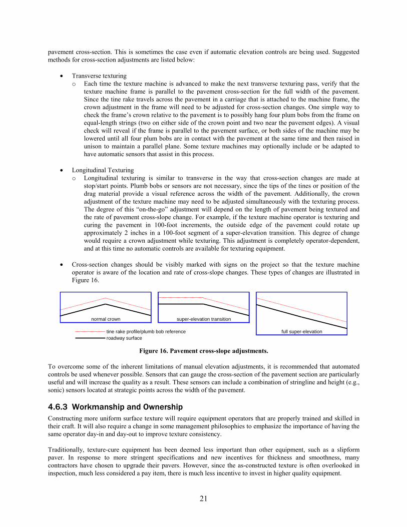
4.6.5 Matching Start and Stop Points Both longitudinal and transverse texturing are interrupted processes. The operator should pay particular attention to matching the texture at start and stop locations. This may be especially critical for transverse texturing with respect to noise. A simple plumb bob on both sides of the texture machine can be used as a reference to gauge both overlap and alignment of the tine rake ( XFigure 17). However, equipment with flexible frames and/or lower quality steering mechanisms will find it more difficult to achieve point matching.
Figure 17. Transverse start/stop point matching.
The primary concern with matching start and stop points for longitudinal texturing is the steering/alignment of the texture machine. When tining, each stop and start requires that the tine rake be raised and the texture machine be backed up to allow some forward movement before the tine rake is lowered into contact with the pavement surface. This slow speed backing up can lead to “crab walking” of the texture machine, causing one side of the machine to back up further than the other. The texture machine should be backed up far enough so that it can be walked forward
22
and realigned with the pavement centerline in preparation for the next texturing section. As mentioned above, longitudinal tining is generally preferred over transverse tining in terms of the potential for constructing a more uniform texture that has improved noise characteristics.
4.6.6 Curing Impacts on Texturing Curing of the pavement is sometimes performed using the same piece of equipment as texturing. As a result, texturing equipment is often referred to as “texture-cure” equipment. The fact that uniform surface texture is time-dependent demands that special attention be given to the curing operation. Specifically, the curing equipment should be maintained to prevent clogging and/or breakdowns, and the refilling of the cure tank should be well planned to minimize delays. Larger cure tank capacities can be beneficial in this regard. When problems occur, curing should always take priority over texturing.
Longitudinal tining typically has an inherent advantage over transverse tining in terms of the ability to provide a high quality curing. During longitudinal tining, the forward motion of the texture-cure equipment can be uninterrupted. This allows the curing compound to be applied concurrently with the tining operation, resulting in a quicker and more consistent curing operation. Most conventional texture-cure equipment used today, when used for transverse tining, requires that the equipment stop periodically and then “back up” in order to apply curing compound.
4.6.7 Over Vibration and Segregation Segregation of the concrete mix due to over vibration on the paver can lead to inconsistencies in surface texture, among numerous other problems. If the vibrators are not operating properly, a concentration of paste (lack of larger aggregate) can occur at the pavement surface in the path of one or more of the vibrators. The effect on texture results from the variability of the firmness of the pavement surface across the width of the slab.
Segregation due to over vibration is visible as what is commonly referred to as “vibrator trails.” These trails are most easily seen on transversely textured pavements where the texture depth is deeper in the “vibrator trails” because the tines penetrated further into the softer, segregated mix directly over the vibrators. In addition to contributing to inconsistent surface texture, segregation can lead to premature pavement failures. Any time the texture machine operator notices that segregation has occurred, the vibrators on the paver should be checked for proper operation.
Quite often, what is commonly attributed to a “vibration problem” is the result of the concrete mixture being used. Mixtures that are extremely gap-graded will tend to segregate during handling and placing. Any excess vibration of these mixtures will only exacerbate their shortcomings. The mixtures will tend to be inconsistent across the width of the slab and especially in the vicinity of the vibrators. While there is a need for a uniform layer of mortar near the surface in order to retain the intended texture, the mixture should be optimized for this, and the use of poorly graded aggregates in the concrete mixture should be avoided.
4.7 Inspecting Surface Textures Until new measurement procedures such as the RoboTex can be adapted for construction quality control, the inspector is left with limited options for comprehensively assuring the quality and consistency of the pavement’s surface texture. Prior to construction, the contractor’s equipment should be inspected with regard to tine spacing and cleanliness. During construction, the inspector should first observe whether the texture is uniform across the slab and then take measurements of the texture depth. Even though specification tolerances may exist for texture depth, it is unrealistic to representatively measure the texture to the extent that a pavement should be rejected. When it is obvious that the texture is not acceptable, the contractor should be notified immediately so that the processes can be corrected.
23
5 Equipment Operation and Maintenance It is in the best interests of nearly all stakeholders to construct concrete pavements as good as possible with the resources given. The “best” pavement is one that offers the requisite structural capacity while providing a surface that is safe, smooth, and quiet. It has been found that the condition of the equipment used to construct concrete pavements can have a direct effect on the texture and thus noise level as vehicles traverse the road. More specifically, machines that are not properly maintained can introduce unwanted vibrations in the fresh concrete. These vibrations, in turn, often lead to subtle texture that will adversely affect tire-pavement noise and possibly smoothness.
The following guidelines describe better practices for maintaining and operating both the paver and texture-cure cart in such a way as to minimize these unwanted vibrations. Explanations of both the necessity and consequences associated with each maintenance and operation topic are provided herein. It must be emphasized that the following recommendations are generalized. The equipment documentation provided by the manufacturer should be referenced for application of this guidance to specific equipment models.
5.1 Concrete Paver We begin with some general principles of a concrete paver that can help build a smoother ride with minimal vibration-related texture: [ X1 X, X2]
1. Weight—the heavier the better, up to a point. During the slipform process, a large mass of concrete is being forced into a specific geometry during the course of a few seconds. The laws of physics require that significant forces be imparted into this mass during this time. As a result, there is an inherent advantage to heavier machines in shaping the concrete to a higher tolerance. Lighter machines can be used and can be just as successful in paving a high-quality product. However, in these situations, careful pre-spreading of the concrete in front of the paver by a placer-spreader or some other effective means is important. This will help avoid overloading the paver and thus should be an integral part of the paving process.
2. Traction—requires weight, power, and friction. With these extreme forces at play, the natural response of a paver will be to resist the concrete being placed and thus resist forward motion. Only with sufficient weight and good traction can the paver advance in a uniform fashion. Traction is enhanced greatly by a stable track line for the paver to operate upon.
3. Uniformity—the more consistent the better. The concrete paver works best when operated in a steady state. Forward motion, vibrator frequency, and other mechanical systems should be operated at a constant rate during placement to the greatest degree possible. Any changes in these due to varying mix, weather, or other factors can inherently introduce changes to the pavement surface. For example, forces acting on a paver are affected by the nature of the concrete mixture. Changes in the mix volumetrics due to segregation, alterations in the batch quantities, admixture dosage (including air), or other factors can change the response of the paver. If these responses are sudden and/or numerous, imperfections in the pavement surface can result.
We now turn to the principal aspects of the equipment that introduce the vibrations. The following three sources are arguably the most significant: [ X3 X]
1. The Engine—Most concrete pavers operate on a diesel engine that operates on the order of 2,000 rpm. Vibrations from rotating machinery such as an engine cannot be avoided. However, measures are commonly taken to isolate these vibrations using dampening mounts. Still, these mounts are imperfect, and their effectiveness is subject to maintenance.
2. The Vibrators—Used on concrete pavers in order to temporarily fluidize the mixture and allow it to be formed to the proper geometry, the vibration frequency is critical and is often “tuned” to provide optimum consolidation of the concrete. Rates of 6,000 to 11,000 vibrations per minutes (VPM) are common. This
24
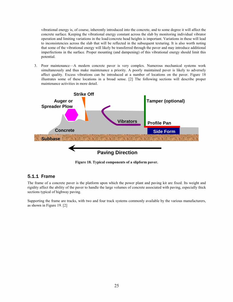
vibrational energy is, of course, inherently introduced into the concrete, and to some degree it will affect the concrete surface. Keeping the vibrational energy constant across the slab by monitoring individual vibrator operation and limiting variations in the load/concrete head heights is important. Variations in these will lead to inconsistencies across the slab that will be reflected in the subsequent texturing. It is also worth noting that some of the vibrational energy will likely be transferred through the paver and may introduce additional imperfections in the surface. Proper mounting (and dampening) of this vibrational energy should limit this potential.
3. Poor maintenance—A modern concrete paver is very complex. Numerous mechanical systems work simultaneously and thus make maintenance a priority. A poorly maintained paver is likely to adversely affect quality. Excess vibrations can be introduced at a number of locations on the paver. Figure 18 X illustrates some of these locations in a broad sense. [2] The following sections will describe proper maintenance activities in more detail.
X
X X
Subbase
Concrete
Auger or Spreader Plow
Strike Off
Vibrators
Tamper (optional)
Profile Pan
Side Form
Paving Direction
Figure 18. Typical components of a slipform paver.
5.1.1 Frame The frame of a concrete paver is the platform upon which the power plant and paving kit are fixed. Its weight and rigidity affect the ability of the paver to handle the large volumes of concrete associated with paving, especially thick sections typical of highway paving.
Supporting the frame are tracks, with two and four track systems commonly available by the various manufacturers, as shown in XFigure 19 X. [ X2 X]
25
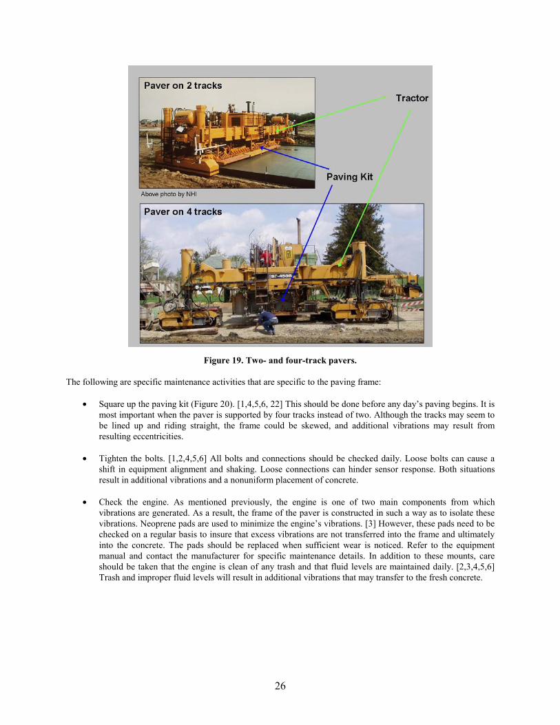
Figure 19. Two- and four-track pavers.
The following are specific maintenance activities that are specific to the paving frame:
• Square up the paving kit (Figure 20). [1,4,5,6, 22] This should be done before any day’s paving begins. It is most important when the paver is supported by four tracks instead of two. Although the tracks may seem to be lined up and riding straight, the frame could be skewed, and additional vibrations may result from resulting eccentricities.
• Tighten the bolts. [1,2,4,5,6] All bolts and connections should be checked daily. Loose bolts can cause a
shift in equipment alignment and shaking. Loose connections can hinder sensor response. Both situations result in additional vibrations and a nonuniform placement of concrete.
• Check the engine. As mentioned previously, the engine is one of two main components from which vibrations are generated. As a result, the frame of the paver is constructed in such a way as to isolate these vibrations. Neoprene pads are used to minimize the engine’s vibrations. [3] However, these pads need to be checked on a regular basis to insure that excess vibrations are not transferred into the frame and ultimately into the concrete. The pads should be replaced when sufficient wear is noticed. Refer to the equipment manual and contact the manufacturer for specific maintenance details. In addition to these mounts, care should be taken that the engine is clean of any trash and that fluid levels are maintained daily. [2,3,4,5,6] Trash and improper fluid levels will result in additional vibrations that may transfer to the fresh concrete.
X X X X X X X X X X X
X X X X X X X X X
X X
X X X X X X X X X X
26
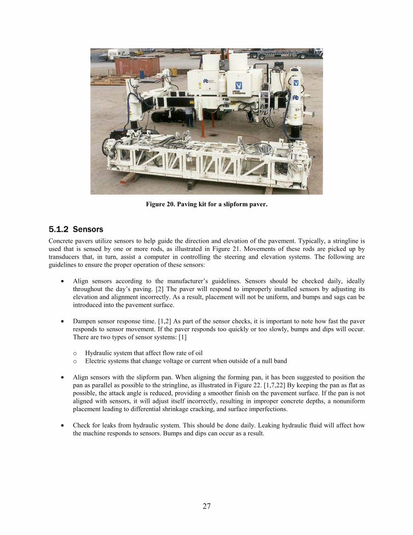
Figure 20. Paving kit for a slipform paver.
5.1.2 Sensors Concrete pavers utilize sensors to help guide the direction and elevation of the pavement. Typically, a stringline is used that is sensed by one or more rods, as illustrated in XFigure 21. Movements of these rods are picked up by transducers that, in turn, assist a computer in controlling the steering and elevation systems. The following are guidelines to ensure the proper operation of these sensors:
• Align sensors according to the manufacturer’s guidelines. Sensors should be checked daily, ideally throughout the day’s paving. [ X2 X] The paver will respond to improperly installed sensors by adjusting its elevation and alignment incorrectly. As a result, placement will not be uniform, and bumps and sags can be introduced into the pavement surface.
• Dampen sensor response time. [ X1 X, X2] As part of the sensor checks, it is important to note how fast the paver responds to sensor movement. If the paver responds too quickly or too slowly, bumps and dips will occur. There are two types of sensor systems: [ X1 X]
o Hydraulic system that affect flow rate of oil o Electric systems that change voltage or current when outside of a null band
• Align sensors with the slipform pan. When aligning the forming pan, it has been suggested to position the pan as parallel as possible to the stringline, as illustrated in XFigure 22 X. [ X1 X, X7 X, X22 X] By keeping the pan as flat as possible, the attack angle is reduced, providing a smoother finish on the pavement surface. If the pan is not aligned with sensors, it will adjust itself incorrectly, resulting in improper concrete depths, a nonuniform placement leading to differential shrinkage cracking, and surface imperfections.
• Check for leaks from hydraulic system. This should be done daily. Leaking hydraulic fluid will affect how the machine responds to sensors. Bumps and dips can occur as a result.
27
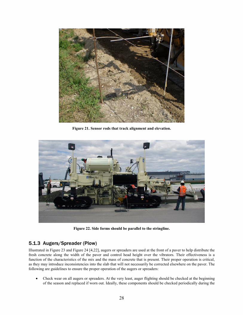
Figure 21. Sensor rods that track alignment and elevation.
Figure 22. Side forms should be parallel to the stringline.
5.1.3 Augers/Spreader (Plow) Illustrated in XFigure 23 X and XFigure 24 X [ X4 X, X22], augers or spreaders are used at the front of a paver to help distribute the fresh concrete along the width of the paver and control head height over the vibrators. Their effectiveness is a function of the characteristics of the mix and the mass of concrete that is present. Their proper operation is critical, as they may introduce inconsistencies into the slab that will not necessarily be corrected elsewhere on the paver. The following are guidelines to ensure the proper operation of the augers or spreaders:
• Check wear on all augers or spreaders. At the very least, auger flighting should be checked at the beginning of the season and replaced if worn out. Ideally, these components should be checked periodically during the
28
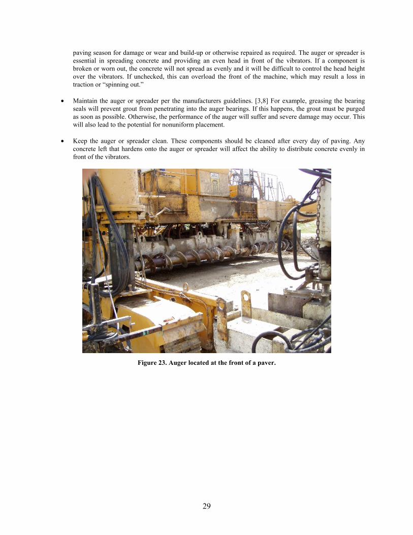
paving season for damage or wear and build-up or otherwise repaired as required. The auger or spreader is essential in spreading concrete and providing an even head in front of the vibrators. If a component is broken or worn out, the concrete will not spread as evenly and it will be difficult to control the head height over the vibrators. If unchecked, this can overload the front of the machine, which may result a loss in traction or “spinning out.”
• Maintain the auger or spreader per the manufacturers guidelines. [ X3 X, X8 X] For example, greasing the bearing seals will prevent grout from penetrating into the auger bearings. If this happens, the grout must be purged as soon as possible. Otherwise, the performance of the auger will suffer and severe damage may occur. This will also lead to the potential for nonuniform placement.
• Keep the auger or spreader clean. These components should be cleaned after every day of paving. Any concrete left that hardens onto the auger or spreader will affect the ability to distribute concrete evenly in front of the vibrators.
Figure 23. Auger located at the front of a paver.
29
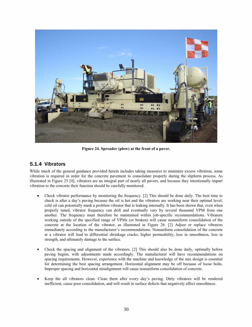
Figure 24. Spreader (plow) at the front of a paver.
5.1.4 Vibrators While much of the general guidance provided herein includes taking measures to minimize excess vibration, some vibration is required in order for the concrete pavement to consolidate properly during the slipform process. As illustrated in XFigure 25 [ X4 X], vibrators are an integral part of nearly all pavers, and because they intentionally impart vibration to the concrete their function should be carefully monitored.
• Check vibrator performance by monitoring the frequency. [2] This should be done daily. The best time to check is after a day’s paving because the oil is hot and the vibrators are working near their optimal level; cold oil can potentially mask a problem vibrator that is leaking internally. It has been shown that, even when properly tuned, vibrator frequency can drift and eventually vary by several thousand VPM from one another. The frequency must therefore be maintained within job-specific recommendations. Vibrators working outside of the specified range of VPMs (or broken) will cause nonuniform consolidation of the concrete at the location of the vibrator, as illustrated in Figure 26. [2] Adjust or replace vibrators immediately according to the manufacturer’s recommendations.
X X X X
Nonuniform consolidation of the concrete at a vibrator will lead to differential shrinkage cracks, higher permeability, loss in smoothness, loss in strength, and ultimately damage to the surface.
X
• Check the spacing and alignment of the vibrators. [ X2 X] This should also be done daily, optimally before paving begins, with adjustments made accordingly. The manufacturer will have recommendations on spacing requirements. However, experience with the machine and knowledge of the mix design is essential for determining the best spacing arrangement. Horizontal alignment may be off because of loose bolts. Improper spacing and horizontal misalignment will cause nonuniform consolidation of concrete.
• Keep the all vibrators clean. Clean them after every day’s paving. Dirty vibrators will be rendered inefficient, cause poor consolidation, and will result in surface defects that negatively affect smoothness.
30
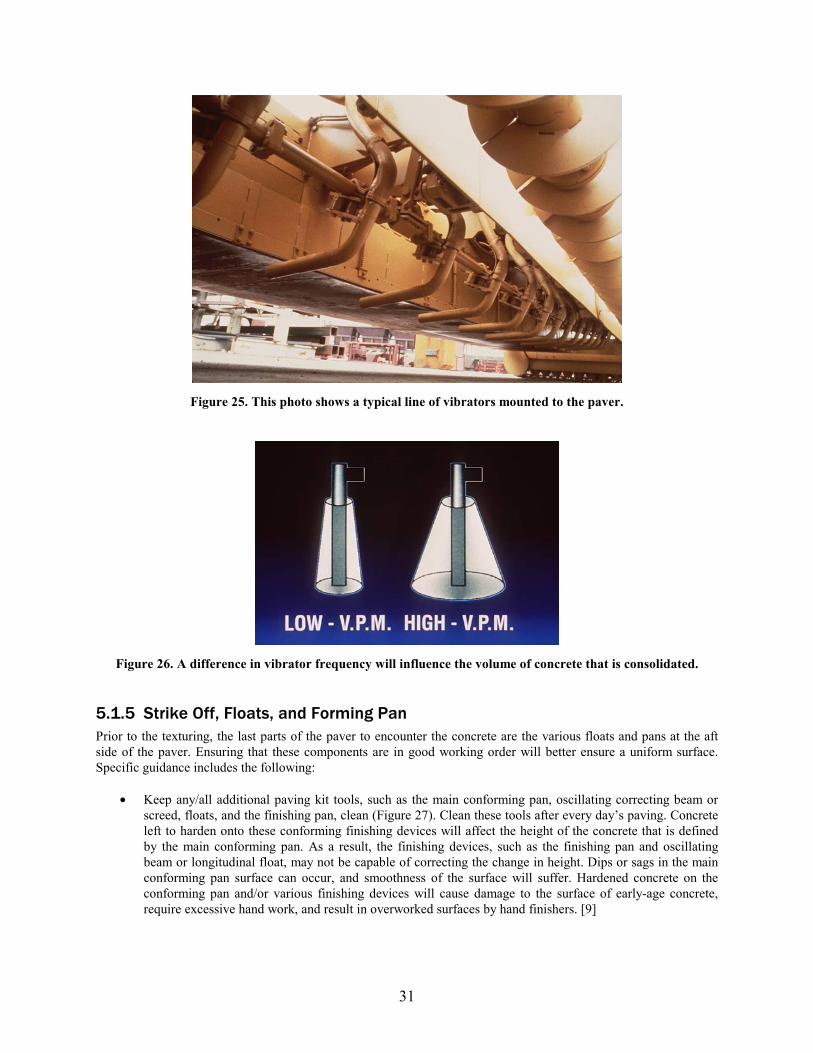
Figure 25. This photo shows a typical line of vibrators mounted to the paver.
Figure 26. A difference in vibrator frequency will influence the volume of concrete that is consolidated.
5.1.5 Strike Off, Floats, and Forming Pan Prior to the texturing, the last parts of the paver to encounter the concrete are the various floats and pans at the aft side of the paver. Ensuring that these components are in good working order will better ensure a uniform surface. Specific guidance includes the following:
• Keep any/all additional paving kit tools, such as the main conforming pan, oscillating correcting beam or screed, floats, and the finishing pan, clean (Figure 27). Clean these tools after every day’s paving. Concrete left to harden onto these conforming finishing devices will affect the height of the concrete that is defined by the main conforming pan. As a result, the finishing devices, such as the finishing pan and oscillating beam or longitudinal float, may not be capable of correcting the change in height. Dips or sags in the main conforming pan surface can occur, and smoothness of the surface will suffer. Hardened concrete on the conforming pan and/or various finishing devices will cause damage to the surface of early-age concrete, require excessive hand work, and result in overworked surfaces by hand finishers. [9]
X X
X X
31
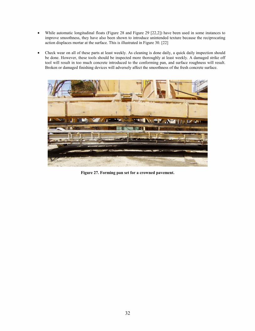
• While automatic longitudinal floats (Figure 28 and Figure 29 [22,2]) have been used in some instances to improve smoothness, they have also been shown to introduce unintended texture because the reciprocating action displaces mortar at the surface. This is illustrated in Figure 30. [22]
X X X X X X X X
X X X X
• Check wear on all of these parts at least weekly. As cleaning is done daily, a quick daily inspection should be done. However, these tools should be inspected more thoroughly at least weekly. A damaged strike off tool will result in too much concrete introduced to the conforming pan, and surface roughness will result. Broken or damaged finishing devices will adversely affect the smoothness of the fresh concrete surface.
Figure 27. Forming pan set for a crowned pavement.
32
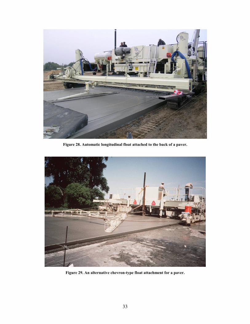
Figure 28. Automatic longitudinal float attached to the back of a paver.
Figure 29. An alternative chevron-type float attachment for a paver.
33
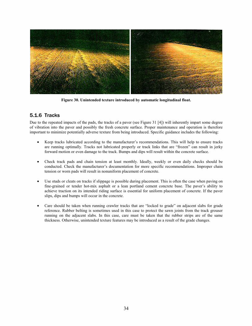
Figure 30. Unintended texture introduced by automatic longitudinal float.
5.1.6 Tracks Due to the repeated impacts of the pads, the tracks of a paver (see XFigure 31 X [4 X]) will inherently impart some degree of vibration into the paver and possibly the fresh concrete surface. Proper maintenance and operation is therefore important to minimize potentially adverse texture from being introduced. Specific guidance includes the following:
• Keep tracks lubricated according to the manufacturer’s recommendations. This will help to ensure tracks are running optimally. Tracks not lubricated properly or track links that are “frozen” can result in jerky forward motion or even damage to the track. Bumps and dips will result within the concrete surface.
• Check track pads and chain tension at least monthly. Ideally, weekly or even daily checks should be conducted. Check the manufacturer’s documentation for more specific recommendations. Improper chain tension or worn pads will result in nonuniform placement of concrete.
• Use studs or cleats on tracks if slippage is possible during placement. This is often the case when paving on fine-grained or tender hot-mix asphalt or a lean portland cement concrete base. The paver’s ability to achieve traction on its intended riding surface is essential for uniform placement of concrete. If the paver slips, dips and bumps will occur in the concrete.
• Care should be taken when running crawler tracks that are “locked to grade” on adjacent slabs for grade reference. Rubber belting is sometimes used in this case to protect the sawn joints from the track grouser running on the adjacent slabs. In this case, care must be taken that the rubber strips are of the same thickness. Otherwise, unintended texture features may be introduced as a result of the grade changes.
34
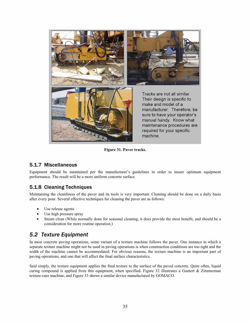
Figure 31. Paver tracks.
5.1.7 Miscellaneous Equipment should be maintained per the manufacturer’s guidelines in order to insure optimum equipment performance. The result will be a more uniform concrete surface.
5.1.8 Cleaning Techniques Maintaining the cleanliness of the paver and its tools is very important. Cleaning should be done on a daily basis after every pour. Several effective techniques for cleaning the paver are as follows:
• Use release agents • Use high pressure spray • Steam clean (While normally done for seasonal cleaning, it does provide the most benefit, and should be a
consideration for more routine operation.)
5.2 Texture Equipment In most concrete paving operations, some variant of a texture machine follows the paver. One instance in which a separate texture machine might not be used in paving operations is when construction conditions are too tight and the width of the machine cannot be accommodated. For obvious reasons, the texture machine is an important part of paving operations, and one that will affect the final surface characteristics.
Said simply, the texture equipment applies the final texture to the surface of the paved concrete. Quite often, liquid curing compound is applied from this equipment, when specified. XFigure 32 X illustrates a Guntert & Zimmerman texture-cure machine, and XFigure 33 X shows a similar device manufactured by GOMACO.
35
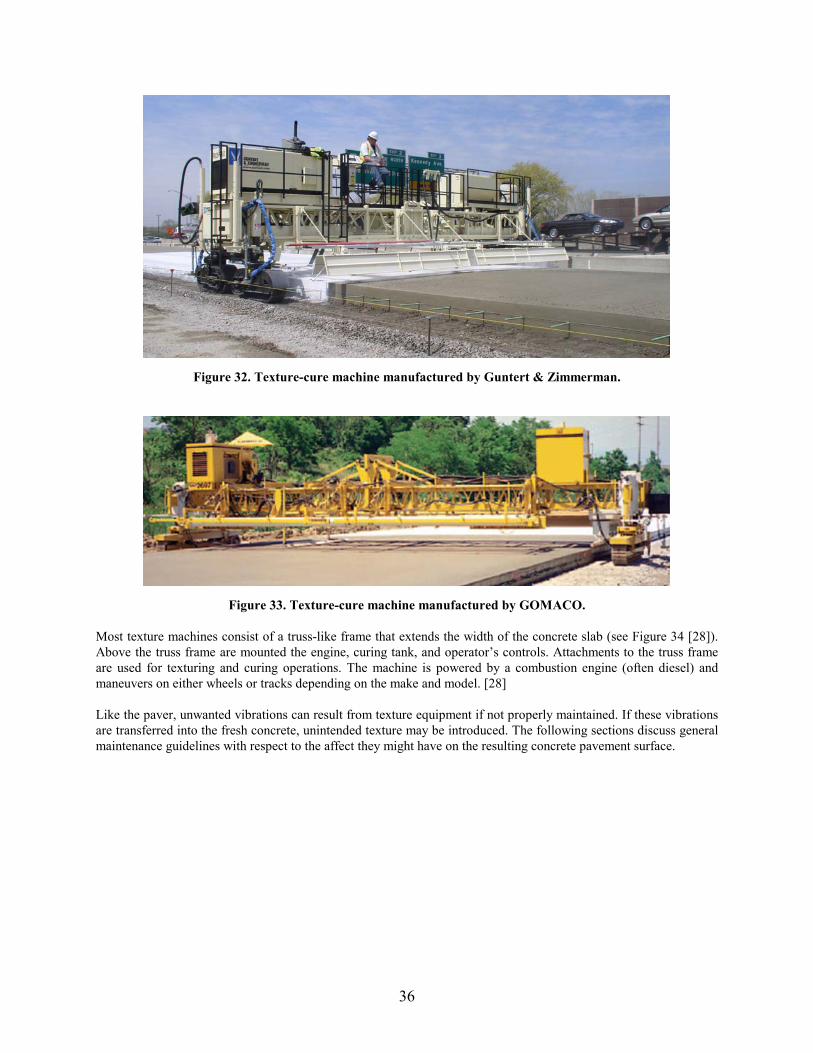
Figure 32. Texture-cure machine manufactured by Guntert & Zimmerman.
Figure 33. Texture-cure machine manufactured by GOMACO.
Most texture machines consist of a truss-like frame that extends the width of the concrete slab (see XFigure 34 X [ X28 X]). Above the truss frame are mounted the engine, curing tank, and operator’s controls. Attachments to the truss frame are used for texturing and curing operations. The machine is powered by a combustion engine (often diesel) and maneuvers on either wheels or tracks depending on the make and model. [ X28]
Like the paver, unwanted vibrations can result from texture equipment if not properly maintained. If these vibrations are transferred into the fresh concrete, unintended texture may be introduced. The following sections discuss general maintenance guidelines with respect to the affect they might have on the resulting concrete pavement surface.
36
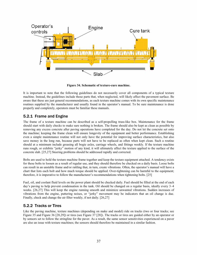
Figure 34. Schematic of texture-cure machine.
It is important to note that the following guidelines do not necessarily cover all components of a typical texture machine. Instead, the guidelines include those parts that, when neglected, will likely affect the pavement surface. Be aware that these are just general recommendations, as each texture machine comes with its own specific maintenance routines supplied by the manufacturer and usually found in the operator’s manual. To be sure maintenance is done properly and completely, operators must be familiar these manuals.
5.2.1 Frame and Engine The frame of a texture machine can be described as a self-propelling truss-like box. Maintenance for the frame should start with daily checks to make sure nothing is broken. The frame should also be kept as clean as possible by removing any excess concrete after paving operations have completed for the day. Do not let the concrete set onto the machine; keeping the frame clean will ensure longevity of the equipment and better performance. Establishing even a simple maintenance routine will not only have the potential for improving surface characteristics, but also save money in the long run, because parts will not have to be replaced as often when kept clean. Such a routine should at a minimum include greasing all bogie axles, carriage wheels, and fittings weekly. If the texture machine runs rough, or exhibits “jerky” motion of any kind, it will ultimately affect the texture applied to the surface of the concrete slab. [ X25 X, X27] Steering problems should be addressed rapidly and corrected.
Bolts are used to hold the texture machine frame together and keep the texture equipment attached. A tendency exists for these bolts to loosen as a result of regular use, and they should therefore be checked on a daily basis. Loose bolts can result in an unstable frame and/or rattling that, in turn, create vibrations. Often, the operator’s manual will have a chart that lists each bolt and how much torque should be applied. Over-tightening can be harmful to the equipment; therefore, it is imperative to follow the manufacturer’s recommendations when tightening bolts. [X25]
Fuel, oil, and coolant fluid levels on the power plant should be checked daily. Fuel should be filled at the end of each day’s paving to help prevent condensation in the tank. Oil should be changed on a regular basis, ideally every 3–4 weeks. [ X26 X, X27 X] This will keep the engine running smooth and minimize unwanted vibrations. Sudden increases of vibrations from the engine, puttering noises, or “jerky” movement may be indicators that an oil change is due. Finally, check and change the air filter weekly, if not daily. [X26 X, X27 X]
5.2.2 Tracks or Tires Like the paving machine, texture machines (depending on make and model) ride on tracks (two or four tracks; see XFigure 35 X and XFigure 36 X [ X28 X, X29 X]) or tires (see XFigure 37 X [ X28 X]). The tracks or tires are guided either by an operator or by sensors set to follow the stringline for the paver. As a result, the same sensor sensitivities experienced on a paver are also an issue with texture machines; the sensors should therefore be maintained in a similar fashion.
37
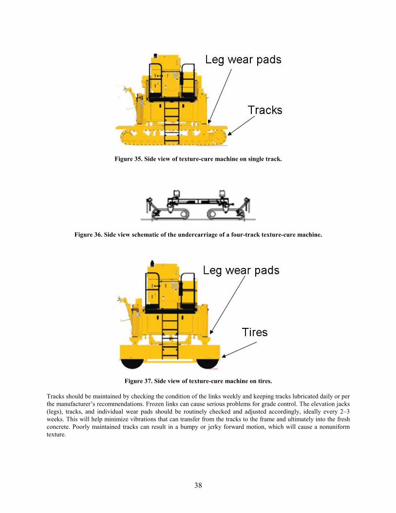
Figure 35. Side view of texture-cure machine on single track.
Figure 36. Side view schematic of the undercarriage of a four-track texture-cure machine.
Figure 37. Side view of texture-cure machine on tires.
Tracks should be maintained by checking the condition of the links weekly and keeping tracks lubricated daily or per the manufacturer’s recommendations. Frozen links can cause serious problems for grade control. The elevation jacks (legs), tracks, and individual wear pads should be routinely checked and adjusted accordingly, ideally every 2–3 weeks. This will help minimize vibrations that can transfer from the tracks to the frame and ultimately into the fresh concrete. Poorly maintained tracks can result in a bumpy or jerky forward motion, which will cause a nonuniform texture.
38
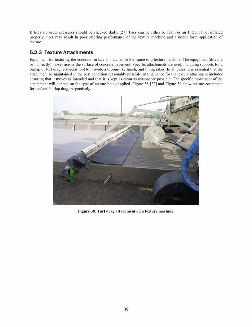
If tires are used, pressures should be checked daily. [ X27 X] Tires can be either be foam or air filled. If not inflated properly, tires may result in poor steering performance of the texture machine and a nonuniform application of texture.
5.2.3 Texture Attachments Equipment for texturing the concrete surface is attached to the frame of a texture machine. The equipment (directly or indirectly) moves across the surface of concrete pavement. Specific attachments are used, including supports for a burlap or turf drag, a special tool to provide a broom-like finish, and tining rakes. In all cases, it is essential that the attachment be maintained in the best condition reasonably possible. Maintenance for the texture attachment includes ensuring that it moves as intended and that it is kept as clean as reasonably possible. The specific movement of the attachment will depend on the type of texture being applied. XFigure 38 [ X22 X] and XFigure 39 X show texture equipment for turf and burlap drag, respectively.
Figure 38. Turf drag attachment on a texture machine.
39
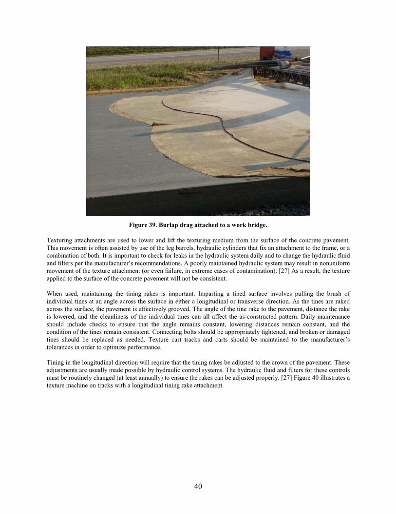
Figure 39. Burlap drag attached to a work bridge.
Texturing attachments are used to lower and lift the texturing medium from the surface of the concrete pavement. This movement is often assisted by use of the leg barrels, hydraulic cylinders that fix an attachment to the frame, or a combination of both. It is important to check for leaks in the hydraulic system daily and to change the hydraulic fluid and filters per the manufacturer’s recommendations. A poorly maintained hydraulic system may result in nonuniform movement of the texture attachment (or even failure, in extreme cases of contamination). [ X27 X] As a result, the texture applied to the surface of the concrete pavement will not be consistent.
When used, maintaining the tining rakes is important. Imparting a tined surface involves pulling the brush of individual tines at an angle across the surface in either a longitudinal or transverse direction. As the tines are raked across the surface, the pavement is effectively grooved. The angle of the tine rake to the pavement, distance the rake is lowered, and the cleanliness of the individual tines can all affect the as-constructed pattern. Daily maintenance should include checks to ensure that the angle remains constant, lowering distances remain constant, and the condition of the tines remain consistent. Connecting bolts should be appropriately tightened, and broken or damaged tines should be replaced as needed. Texture cart tracks and carts should be maintained to the manufacturer’s tolerances in order to optimize performance.
Tining in the longitudinal direction will require that the tining rakes be adjusted to the crown of the pavement. These adjustments are usually made possible by hydraulic control systems. The hydraulic fluid and filters for these controls must be routinely changed (at least annually) to ensure the rakes can be adjusted properly. [ X27 X] XFigure 40 X illustrates a texture machine on tracks with a longitudinal tining rake attachment.
40
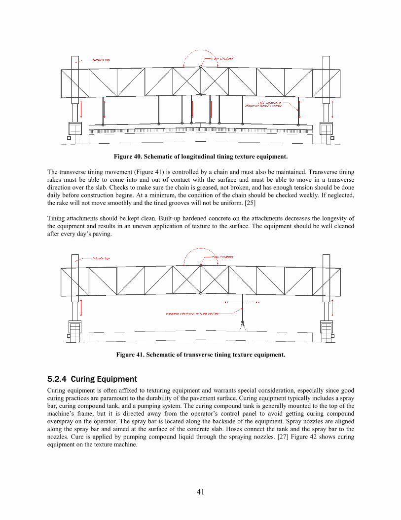
Figure 40. Schematic of longitudinal tining texture equipment.
The transverse tining movement ( XFigure 41 X) is controlled by a chain and must also be maintained. Transverse tining rakes must be able to come into and out of contact with the surface and must be able to move in a transverse direction over the slab. Checks to make sure the chain is greased, not broken, and has enough tension should be done daily before construction begins. At a minimum, the condition of the chain should be checked weekly. If neglected, the rake will not move smoothly and the tined grooves will not be uniform. [X25 X]
Tining attachments should be kept clean. Built-up hardened concrete on the attachments decreases the longevity of the equipment and results in an uneven application of texture to the surface. The equipment should be well cleaned after every day’s paving.
Figure 41. Schematic of transverse tining texture equipment.
5.2.4 Curing Equipment Curing equipment is often affixed to texturing equipment and warrants special consideration, especially since good curing practices are paramount to the durability of the pavement surface. Curing equipment typically includes a spray bar, curing compound tank, and a pumping system. The curing compound tank is generally mounted to the top of the machine’s frame, but it is directed away from the operator’s control panel to avoid getting curing compound overspray on the operator. The spray bar is located along the backside of the equipment. Spray nozzles are aligned along the spray bar and aimed at the surface of the concrete slab. Hoses connect the tank and the spray bar to the nozzles. Cure is applied by pumping compound liquid through the spraying nozzles. [X27 X] XFigure 42 X shows curing equipment on the texture machine.
41
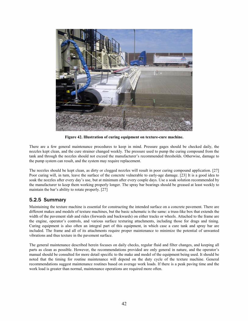
Figure 42. Illustration of curing equipment on texture-cure machine.
There are a few general maintenance procedures to keep in mind. Pressure gages should be checked daily, the nozzles kept clean, and the cure strainer changed weekly. The pressure used to pump the curing compound from the tank and through the nozzles should not exceed the manufacturer’s recommended thresholds. Otherwise, damage to the pump system can result, and the system may require replacement.
The nozzles should be kept clean, as dirty or clogged nozzles will result in poor curing compound application. [ X27 X] Poor curing will, in turn, leave the surface of the concrete vulnerable to early-age damage. [X23 X] It is a good idea to soak the nozzles after every day’s use, but at minimum after every couple days. Use a soak solution recommended by the manufacturer to keep them working properly longer. The spray bar bearings should be greased at least weekly to maintain the bar’s ability to rotate properly. [X27 X]
5.2.5 Summary Maintaining the texture machine is essential for constructing the intended surface on a concrete pavement. There are different makes and models of texture machines, but the basic schematic is the same: a truss-like box that extends the width of the pavement slab and rides (forwards and backwards) on either tracks or wheels. Attached to the frame are the engine, operator’s controls, and various surface texturing attachments, including those for drags and tining. Curing equipment is also often an integral part of this equipment, in which case a cure tank and spray bar are included. The frame and all of its attachments require proper maintenance to minimize the potential of unwanted vibrations and thus texture in the pavement surface.
The general maintenance described herein focuses on daily checks, regular fluid and filter changes, and keeping all parts as clean as possible. However, the recommendations provided are only general in nature, and the operator’s manual should be consulted for more detail specific to the make and model of the equipment being used. It should be noted that the timing for routine maintenance will depend on the duty cycle of the texture machine. General recommendations suggest maintenance routines based on average work loads. If there is a peak paving time and the work load is greater than normal, maintenance operations are required more often.
42
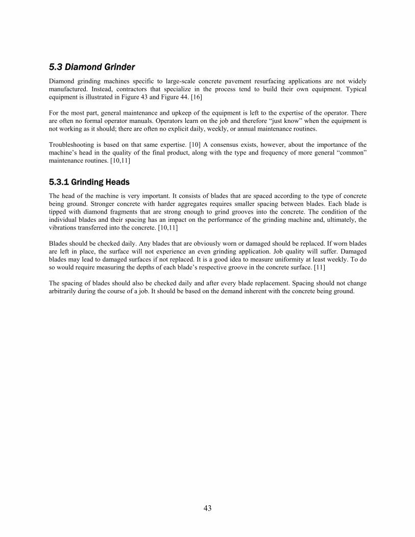
5.3 Diamond Grinder Diamond grinding machines specific to large-scale concrete pavement resurfacing applications are not widely manufactured. Instead, contractors that specialize in the process tend to build their own equipment. Typical equipment is illustrated in Figure 43 and Figure 44. [16] For the most part, general maintenance and upkeep of the equipment is left to the expertise of the operator. There are often no formal operator manuals. Operators learn on the job and therefore “just know” when the equipment is not working as it should; there are often no explicit daily, weekly, or annual maintenance routines. Troubleshooting is based on that same expertise. [10] A consensus exists, however, about the importance of the machine’s head in the quality of the final product, along with the type and frequency of more general “common” maintenance routines. [10,11]
5.3.1 Grinding Heads The head of the machine is very important. It consists of blades that are spaced according to the type of concrete being ground. Stronger concrete with harder aggregates requires smaller spacing between blades. Each blade is tipped with diamond fragments that are strong enough to grind grooves into the concrete. The condition of the individual blades and their spacing has an impact on the performance of the grinding machine and, ultimately, the vibrations transferred into the concrete. [10,11] Blades should be checked daily. Any blades that are obviously worn or damaged should be replaced. If worn blades are left in place, the surface will not experience an even grinding application. Job quality will suffer. Damaged blades may lead to damaged surfaces if not replaced. It is a good idea to measure uniformity at least weekly. To do so would require measuring the depths of each blade’s respective groove in the concrete surface. [11] The spacing of blades should also be checked daily and after every blade replacement. Spacing should not change arbitrarily during the course of a job. It should be based on the demand inherent with the concrete being ground.
43
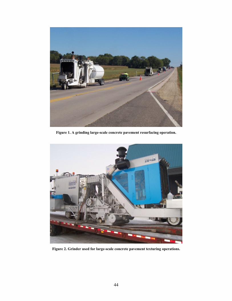
Figure 1. A grinding large-scale concrete pavement resurfacing operation.
Figure 2. Grinder used for large-scale concrete pavement texturing operations.
44
5.3.2 General Maintenance Improving the quality of diamond grinding often can be achieved through proper maintenance of the equipment. General guidance for better practice in this regard includes the following:
• Check all fluid levels daily.
• Inspect the machine frame and all welds for cracks. Repair as appropriate.
• Check drive wheels annually for cracks or tears and fix as necessary.
• Check profile wheels annually. Replace when half the urethane life is gone, if cracked, or when flat. Be sure bearings are within specifications, and check brackets for cracks, loose pins, or loose bushings.
• Be sure all bushings, pins, and bearings are not loose. Check at least annually.
• Be sure the vacuum system is working appropriately. Recommended as an annual check, this should be observed more regularly and addressed as soon as possible if something is not working properly. The effectiveness of the vacuum system will affect the longevity of the blades.
• The hydraulic system should be thoroughly inspected annually. Pumps and motors should be removed and sent for cleaning. Disassemble pump drives to replace bearings and seals. Replace gears and shafts as needed and reassemble. Drain the hydraulic tank, open the tank, clean it, and refill it. Replace bad hydraulic hoses and fittings. Start up the machine, set pressures, and inspect for leaks.
• The engine should also undergo annual maintenance. Take and send oil samples to lab. Change all fluids and filters. Inspect the engine for oil leaks and fix any that are found. Replace the rear main seal. Inspect the exhaust system for leaks, rust, and cracks. Inspect engine belts and replace as needed. Inspect the low oil pressure shutdown system, switches, and other instrumentation for proper operation and fix as needed.
5.3.3 Hydraulic Systems Regarding hydraulic systems, some practical guidance includes the following: [ X12 X]
• Keep it clean! Dirt kills the hydraulic system. Change filters regularly as per the user’s manual. Filters should be changed at least once every 50 hours or 2 weeks.
• Prevent dirt from getting in downstream of the filters.
• Dirt is able to infiltrate downstream of the filters when repairs are made out in the open.
• If repairs are necessary, provide as much protection as possible from even the slightest of breezes.
• Rough handling of components during assembly and disassembly could cause chipping, resulting in diminished service life.
• Over tightening bolts could also cause chipping and reduce service life. Be sure to follow the user’s manual on proper tightening techniques.
• Replace leaking seals or cylinders as necessary. Otherwise, damage to vital components may result. Refer to the user’s manual for ideal maintenance routines for specific models.
45
References 1. American Concrete Pavement Association, Concrete Paving Technology: Constructing Smooth Concrete
Pavements, Report RB006P, 2003. 2. Federal Highway Administration, Construction of Portland Cement Concrete Pavements, Participant’s
Manual, National Highway Institute Course No. 131033, Report FHWA HI-96-027, 1996. 3. Personal Communication with Fred Hite, Power Pavers, 31 December 2007. 4. Terex Corporation, Lubrication and Maintenance Interval Chart. 5. Huron Manufacturing Corporation, Service and Maintenance Manual. 6. MBW Incorporated, Concrete Curb and Gutter Slipform Paver Operating Instructions, 1998. 7. Guntert & Zimmerman Const. Div., Inc., Paving Guidelines for Best Results, 18th
P Annual Concrete PavingSchool, 25-27 January 2005.
8. GOMACO Corporation, Lubrication and Maintenance Service Interval Chart, Operator’s Manual. 9. Grogg, Max G. and Smith, Kurt D. PCC Pavement Smoothness: Characteristics and Best Practices for
Construction, Report FHWA-IF-02-025, October 2001. 10. Personal Communication with Gary Aamold, Penhall International Corporation, on 20 December 2007. 11. Personal Communication with Brady Knish, Knish Corporation, 19 December 2007. 12. GOMACO Corporation, Commander III User’s Manual. 13. ASTM International, St andard Test Method for Measuring Pavement Macrotexture Depth using a
Volumetric Technique, Specification E965-96, 2001. 14. Federal Highway Administration, Surface Texture for Asphalt and Concrete Pavements, Technical
Advisory T 5040.36, 17 June 2005. 15. American Association of State Highway and Transportation Officials, Standard Specification for Burlap
Cloth Made from Jute or Kenaf and Cotton Mats, Specification M 182, 2005. 16. Personal Communication with Terry Kraemer, Diamond Surface, Inc, 2008. 17. Meininger, Richard, Various Photographs, 2004. 18. Cackler, E.T., et. al., C oncrete Pavement Surface Characteristics: Evaluation of Current Methods for
Controlling Tire-Pavement Noise, Final Report of FHWA Cooperative Agreement DTFH61-01-X-00042, Project 15, 2006.
19. Ferragut, T., Rasmussen, R.O., Wiegand, P., Mun, E., and E.T. Cackler, ISU-FHWA-ACPA Concrete Pavement Surface Characteristics Program Part 2: Preliminary Field Data Collection, National Concrete Pavement Technology Center Report DTFH61-01-X-00042 (Project 15, Part 2), 2007.
20. FEHRL, Guidance Manual for the Implementation of Low-Noise Road Surfaces, Report 2006/02, Ed. by Phil Morgan, TRL, 2006.
21. Sandberg, Ulf and J. Ejsmont, Tyre/Road Noise Reference Book, Informex, Handelsbolag, Sweden, 2002. 22. Guntert & Zimmerman Const. Div., Inc. Various Photographs, 2008. 23. Taylor, P.C., et. al., Integrated Materials and Construction Practices for Concrete Pavement, A State-of-
P
the-Practice Manual, Report FHWA-HIF-07-004, 2006. 24. Rasmussen, R.O., et. al., The Little Book of Quieter Pavements, Report FHWA-IF-08-004, 2007. 25. Personal Communication with Ron Meskis and Marco Cantu, Guntert & Zimmerman Const. Div., Inc., 7
March 2008. 26. Terex Corporation, CMI Operation and Maintenance: Texture/Cure Machine TC 140&280. 27. GOMACO Corporation, Maintenance: Chapter IV, TC400/600. 28. GOMACO Corporation, Texturing / Curing Machines, Product Brochure, 2006. 29. Guntert & Zimmerman Const. Div., Inc., Various Engineering Drawings, 4/20/2008. 30. Minnesota Department of Transportation, Minnesota’s Astro-Turf Drag Technique Texturing Concrete
Pavements, http://www.dot.state.mn.us/materials/researchastroturf.html (last accessed 6/2008).
HTU UTH
46
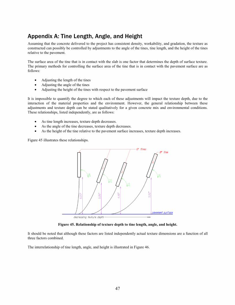
Appendix A: Tine Length, Angle, and Height Assuming that the concrete delivered to the project has consistent density, workability, and gradation, the texture as constructed can possibly be controlled by adjustments to the angle of the tines, tine length, and the height of the tines relative to the pavement.
The surface area of the tine that is in contact with the slab is one factor that determines the depth of surface texture. The primary methods for controlling the surface area of the tine that is in contact with the pavement surface are as follows:
• Adjusting the length of the tines • Adjusting the angle of the tines • Adjusting the height of the tines with respect to the pavement surface
It is impossible to quantify the degree to which each of these adjustments will impact the texture depth, due to the interaction of the material properties and the environment. However, the general relationship between these adjustments and texture depth can be stated qualitatively for a given concrete mix and environmental conditions. These relationships, listed independently, are as follows:
• As tine length increases, texture depth decreases. • As the angle of the tine decreases, texture depth decreases. • As the height of the tine relative to the pavement surface increases, texture depth increases.
XFigure 45 illustrates these relationships.
Figure 45. Relationship of texture depth to tine length, angle, and height.
It should be noted that although these factors are listed independently actual texture dimensions are a function of all three factors combined.
The interrelationship of tine length, angle, and height is illustrated in Figure 46.
47
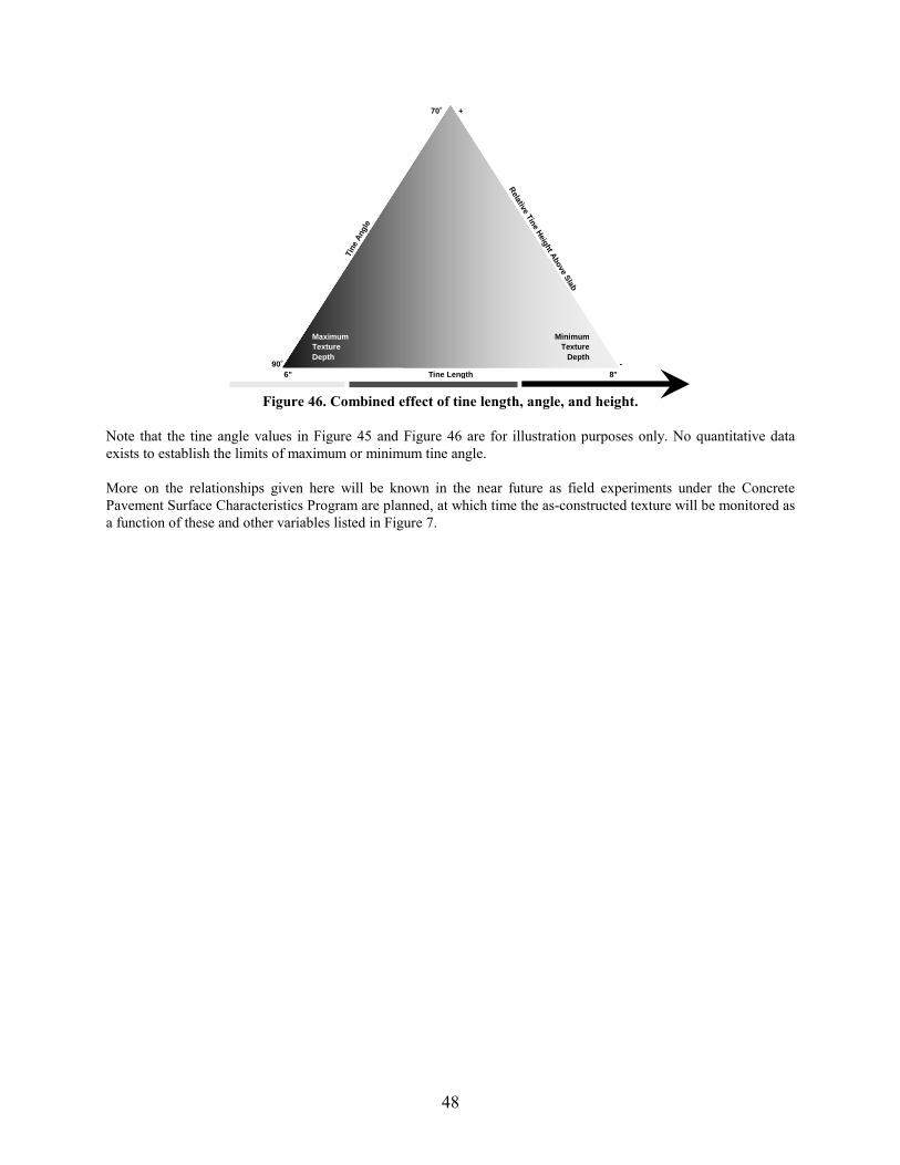
70˚ +
Tine
Ang
le
Relative
TineH
eight Above
Slab Maximum Texture Depth
Minimum Texture
Depth
6" Tine Length 8" 90˚
Figure 46. Combined effect of tine length, angle, and height.
Note that the tine angle values in XFigure 45 X and XFigure 46 X are for illustration purposes only. No quantitative data exists to establish the limits of maximum or minimum tine angle.
More on the relationships given here will be known in the near future as field experiments under the Concrete Pavement Surface Characteristics Program are planned, at which time the as-constructed texture will be monitored as a function of these and other variables listed in XFigure 7 X.
48

Appendix B: Texturing Better Practices Checklist In addition to the guidance provided in XFigure 2 X and XFigure 3 X, the following checklists can be used to establish priority items to check during construction.
Mixture Design/Mix Proportioning—check the following for consistency:
• Gradation • Paste volume • Mortar volume • Check bleeding of concrete per ASTM C 232
Pre-Construction
• Drag o Check for adequate drag width—for full paving width coverage. o Check for adequate drag length to attain nominal depth. o Clean drag material—remove latency from previous days’ paving or replace material. o Ensure that replacement drag material is on hand—should be readily available. o Ensure that ballast for drag is available—typically sand or lumber. o Confirm that all texturing and curing equipment has been properly maintained and is ready for
uninterrupted operation. o Check that the correct amount of curing compound is on the project and available at the correct refill
interval. o Ensure adequate drag connection and support.
• Tine o Check the tine spacing—confirm that nominal spacing is met. o Check that all tines are the same length. o Confirm that all tines are straight. o Clean the tines. o Mark superelevation transitions to allow for operator to make crown adjustments as appropriate. o Confirm that all texturing and curing equipment has been properly maintained and is ready for
uninterrupted operation. o Check that the correct amount of curing compound is on the project and available at the correct refill
interval.
Construction
• Drag o Moisten the drag material before commencing the texturing operation, especially burlap. o Add ballast across the full width of the drag material to achieve the nominal texture depth required. o Adjust the ballast as weather and mixture conditions change. o Finish texturing before the surface of the pavement experiences any drying, and then apply curing
compound without delay. o Remove excess buildup of mortar as necessary to maintain the intended texture. o Replace the drag material as necessary to ensure desired texture.
• Tine o Operate the texture equipment at a consistent speed. o Adjust tine angle, length, and downward pressure to achieve the nominal texture depth required. o Finish texturing before the surface of the pavement experiences any drying, and then apply curing
compound without delay.
49

o Adjust the timing of texture operations as weather and mixture conditions change. o Clean paste buildup off of the tines as necessary. o Adjust elevations through superelevation transitions. o Replace bent or broken tines as necessary.
Table 1. Checklist of equipment operation and maintenance activities.
Paver Parts Daily Weekly Monthly Annually
Frame
Clean well after day’s work.
Check and align paving kit before paving.
Check and tighten bolts and connections.
Check the engine.
Sensors
Check alignment.
Check gages.
Dampen appropriately.
Auger
Check for and replace broken blades.
Clean well after day’s work.
Grease and check bearing seals.
Strike off, floats, plows
Clean well after day’s work.
Vibrators
Check spacing and horizontal alignment before paving.
Check individual speeds at end of day’s paving. Replace broken ones; adjust those that vibrate too fast or too slow.
Racks/Tires
Check track lubrication.
Check tire pressure.
Assess trackline traction requirements.
Miscellaneous (Dependant on manufacture’s recommendations.)
Lube fittings
Check all fluid levels and make sure they are full before paving.
Check the battery and alternator.
Change oil in gearboxes.
Change engine oil and filters.
Change breather filter element in hydraulic oil tank.
Check the belts.
Change oil and filters for hydraulic system.
50
Appendix C: Definitions The following include some simple definitions of a few of the unconventional terms used in this document:
• A-weighting—a commonly used means to adjust sound levels in such a way as to mimic human sensitivity to different frequencies. Levels that are A-weighted are sometimes reported in units of A-weighted decibels, or dBA.
• CPSCP—the Concrete Pavements Surface Characteristics Program, a collaborative effort that has been jointly funded by the FHWA, ACPA, National Concrete Pavement Technology Center, and various state DOTs under Pooled Fund TPF-5(139). The objectives have included development of a catalog of surface characteristics of existing concrete pavements, exploration of innovative techniques for improving surface characteristics, and development of guidance to improve concrete pavement surface characteristics.
• Decibels (dB)—the units of sound level. This is a logarithmic transformation of sound pressure or sound intensity with a basis of a reference sound level.
• Frequency—how often sound pressure impulses (or texture) repeat. When expressed in Hertz (Hz), this is simply frequency in impulses per second. The inverse of this is wavelength, which for sound is sometimes reported in seconds and, for both sound and texture, can be reported as a distance in inches or feet.
• Noise—any sound believed to be objectionable. This is therefore a subjective thing. • On-Board Sound Intensity (OBSI)—a measurement technique that evaluates tire-pavement noise closely
by placing specialized microphone probes near the tire-pavement contact area. Measurements are commonly performed at 60 mph using an ASTM F 2493 Standard Reference Test Tire.
• Sound level—a scientific measure of the “volume” of a sound. • Traffic noise—noise generated by a traffic stream. This includes all sources generated by the traffic,
including propulsion noise, tire-pavement noise, and aerodynamic noise. • Tire-pavement noise—noise generated by tires rolling along a pavement surface. • Two-lift concrete paving—a construction technique, commonly used outside the United States, in which
two layers of concrete are combined (placed in sequence, commonly “wet on wet”) to form one monolithic slab. The bottom layer is typically thicker and is designed for both structural capacity and economy. The top layer is typically constructed with a higher-quality concrete with an emphasis on durability under traffic and weather.
51

To better understand tire-pavement noise…
• FHWA, The Little Book of Quieter Pavements [24] To better understand good practices for concrete paving…
• CP Tech Center, Integrated Materials and Construction Practices for Concrete Pavement [23]
Appendix D: For More Information The following reports and websites provide practical information that was not included herein for the sake of brevity.
Reports
X
X X
Websites Concrete Pavement Surface Characteristics Program
• http://www.SurfaceCharacteristics.com UTH American Concrete Pavement Association
• http://www.Pavement.com UTH Internationa
HTU
l Grooving & Grinding Association • http://www.IGGA.net UTH
HTU
HTU
52