Embed Size (px)
Citation preview

National Training Course on Radiation Protection
for Radiological Practice performed outside Radiology using
Fluoroscopy
(Tel Aviv, 3rd of June, 2018)
How to protect the patient in fluoroscopy
guided procedures, including interventional
cardiology
Renato Padovani, ICTP, Italy

Key topics
• Why is it necessary to consider radiation protection
of patients?
• How do X ray technique and physical factors affect
patient dose?
• What is the role of the operator in patient dose
management?
• How to manage patient dose using physical and
equipment factors?
• To add: specific examples orthopaedics, gastro,
etc. cardio
How to protect the patient 2
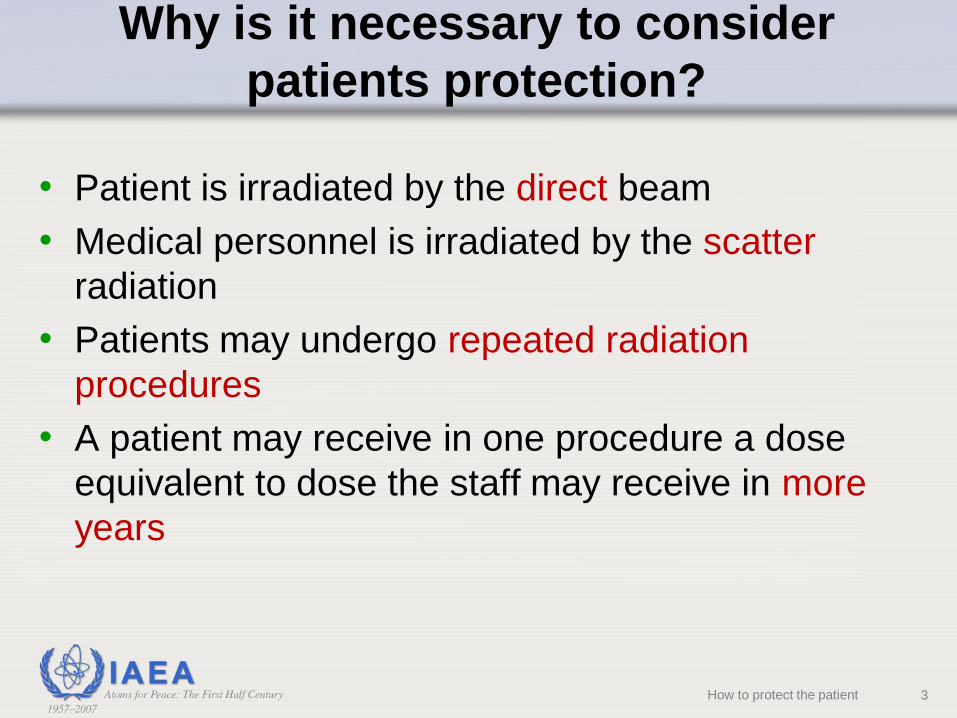
Why is it necessary to consider
patients protection?
• Patient is irradiated by the direct beam
• Medical personnel is irradiated by the scatter
radiation
• Patients may undergo repeated radiation
procedures
• A patient may receive in one procedure a dose
equivalent to dose the staff may receive in more
years
How to protect the patient 3

Why is it necessary to consider
patients protection?
• There are no fluoroscopy time constraints
• Poor fluoroscopy technique can multiply patient
dose rates many times above normal (>10 times)
Implies There is a potential for high and
unnecessary patient doses
and, skin injury in high dose procedures (e.g. > 30
min fluoroscopy time and hundred of images)
How to protect the patient

Why is it necessary to consider patients
protection?
15 minutes of fluoroscopy at 40 mGy/min skin dose
rate cumulative skin dose: 0.6 Gy
With thick patients, the radiation dose can be quite
high with the possibility of radiation injury
X ray system not optimized and operators not trained
in radiation protection could increase patient dose by
a factor of 10:
Skin necrosis from
Coronary Angioplasty
Skin Doses > 20 Gy
>100 minutes fluoro time
5How to protect the patient
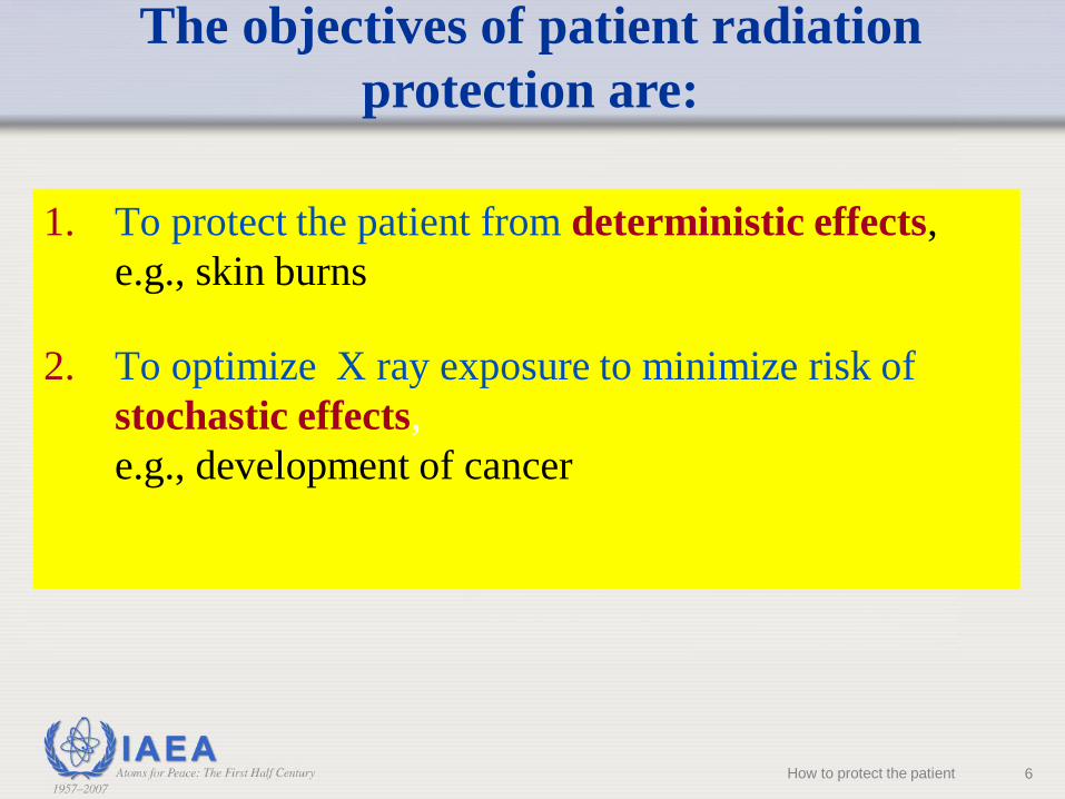
1. To protect the patient from deterministic effects,
e.g., skin burns
2. To optimize X ray exposure to minimize risk of
stochastic effects,
e.g., development of cancer
The objectives of patient radiation
protection are:
6How to protect the patient
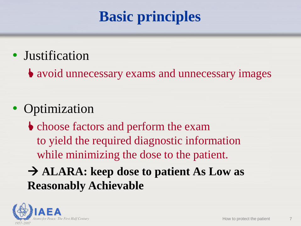
Basic principles
• Justification
avoid unnecessary exams and unnecessary images
• Optimization
choose factors and perform the exam
to yield the required diagnostic information
while minimizing the dose to the patient.
ALARA: keep dose to patient As Low as
Reasonably Achievable
7How to protect the patient

• Patient entrance surface dose rate
• X ray beam area
• Beam ON time
(Note: these same factors influence staff doses)
Factors affecting patient dose in
fluoroscopy
8How to protect the patient

• Patient dependent factors:• body mass or body thickness in the beam
• complexity of the lesion and anatomic target structure
• previous radiation exposure
• radiosensitivity of some patients
• Equipment dependent factors:• Setting of dose rates in pulsed fluoro- and continuous fluoro
mode
• Selected image quality (higher higher dose)
• last image hold, acquisition
• collimation
• appropriate quality control
Factors affecting patient dose in
fluoroscopy
9How to protect the patient

Factors affecting patient
entrance surface dose rate
• Thickness & composition of patient.
• X ray beam quality (kVp, filtration)
• II Mag mode (Normal, Mag 1, Mag 2, etc.)
• II Dose mode (low, medium, high)
• Pulse rate and pulse width for pulsed fluoro
• Anti-scatter grid
• Angulation
11How to protect the patient

X raysource
Absorbed radiation
Scattered radiation
Transmitted
radiation
Image formation
Patient body
Primary (direct) beam
Attenuation
12How to protect the patient

Image formation
Only a small percentage (typically ~1%)
penetrate through to create the image.
As beam penetrates patient,
x rays ionize tissue
Beam entering patient typically 100 - 500x
more intense than exit beam100 % in
1 % out
13How to protect the patient
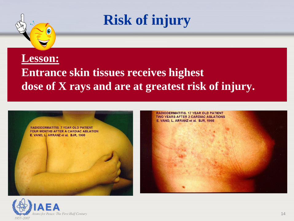
Risk of injury
Lesson:
Entrance skin tissues receives highest
dose of X rays and are at greatest risk of injury.
14

X ray intensity decreases rapidly with distance from source;
conversely, intensity increases rapidly with closer distances to source.
d
d/2d/4
d/8
Inverse Square Law
Intensity
64 16 4 1
15How to protect the patient

All other conditions unchanged, moving patient toward or away from
the X ray tube can significantly affect dose rate to the skin
1 unit 4 units 16 units 64 units
d
d/2d/4
d/8
Inverse Square Law & the Patient
Lesson: Keep the X ray tube at the practicable
maximum distance from the patient.
16

Inverse Square Law &
The Image Receptor (Image Intensifier)
All other conditions unchanged, moving image receptor toward
patient lowers radiation output rate and lowers skin dose rate.
17
4 units of
intensityImage
Receptor
2 units of
intensity
Image
Receptor
Image
Receptor
Lesson: Keep the image receptor as close to the
patient as is practicable for the procedure.
Remember,
ABC
adjusts dose
to maintain
same image
brightness
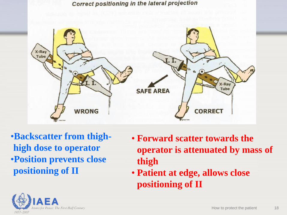
•Backscatter from thigh-
high dose to operator
•Position prevents close
positioning of II
• Forward scatter towards the
operator is attenuated by mass of
thigh
• Patient at edge, allows close
positioning of II
18How to protect the patient

Scatter Levels Hip Lat Cross Table
Projection* (μSv per 1000 cGy cm2)
Distance (m) -1 -0.5 0 0.5 1
1.5 1 1 1 1 1
1 1 2 2 2 1
0.5 2 5 5 3 2
0 3 15 29 6 2
Feet Head
0 73 252 1080 114 11
0.5 73 160 301 104 8
1 48 70 105 85 24
1.5 24 37 48 43 30
• Dose rate substantially higher on X ray focus side of patient compared to
Image intensifier side because of scatter from the patient
*Occupational exposure from common fluoroscopic projections used in orthopedic Surgery Nicholas Theocharopoulos et al Journal
of Bone and Joint Surgery; Sep 2003; 85, 9;
19
X ray tube side
Image intensifier
side
How to protect the patient
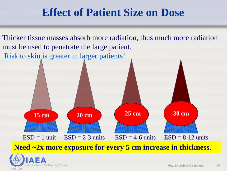
Thicker tissue masses absorb more radiation, thus much more radiation
must be used to penetrate the large patient.
Risk to skin is greater in larger patients!
15 cm 20 cm 25 cm 30 cm
ESD = 1 unit ESD = 2-3 units ESD = 4-6 units ESD = 8-12 units
Need ~2x more exposure for every 5 cm increase in thickness.
Effect of Patient Size on Dose
20How to protect the patient

Lowest (GOOD) ---------------------------- Highest (BAD)
Image Intensifier close to
patient, X ray tube far from
patient
Image intensifier far from
patient, X ray tube close to
patientFrom: J American College of Cardiology 2004; 44(11): 2259-82
Entrance Dose to Patient vs. Imaging
Geometry
21How to protect the patient
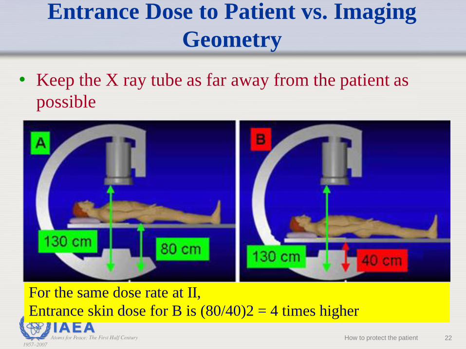
For the same dose rate at II,
Entrance skin dose for B is (80/40)2 = 4 times higher
• Keep the X ray tube as far away from the patient as
possible
Entrance Dose to Patient vs. Imaging
Geometry
22How to protect the patient
How do I reduce my radiation risk?
23
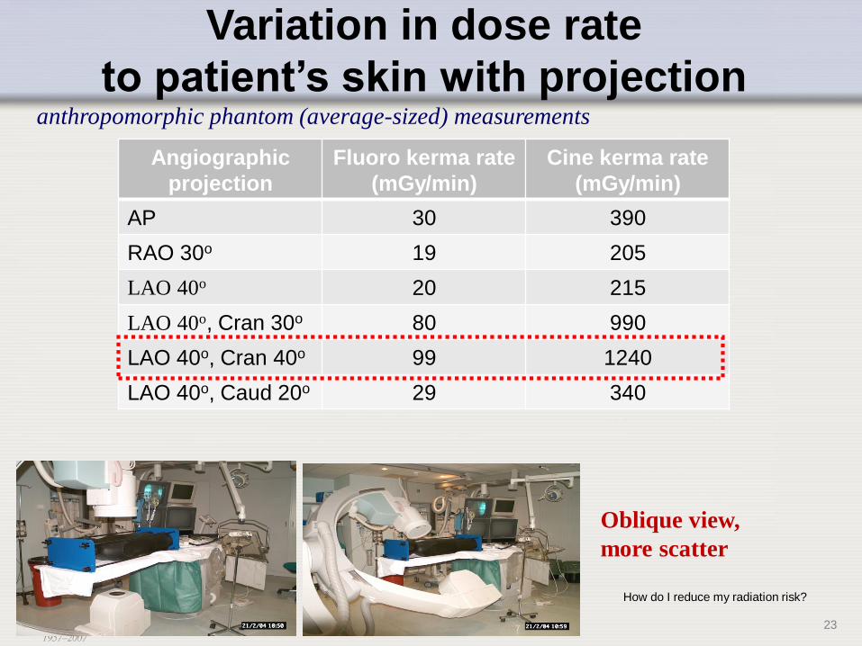
Variation in dose rate
to patient’s skin with projectionanthropomorphic phantom (average-sized) measurements
Oblique view,
more scatter
Angiographic
projection
Fluoro kerma rate
(mGy/min)
Cine kerma rate
(mGy/min)
AP 30 390
RAO 30o 19 205
LAO 40o 20 215
LAO 40o, Cran 30o 80 990
LAO 40o, Cran 40o 99 1240
LAO 40o, Caud 20o 29 340

Thicker tissue masses absorb more radiation, thus much more
radiation must be used.
• Higher dose to patient when imaging through steep projections
• Risk to skin is greater with steeper beam angles!
Tissue Thickness & Dose Rate
24How to protect the patient

• Grids
• Grid is placed in front of the image detector
• A grid reduces the effect of scatter (degrading of image
contrast), BUT it also attenuates the primary X ray beam (both
scatter & primary hit grid strips).
• typically require a 2 times increase in patient dose rate to
compensate for attenuation & maintain same X ray intensity at
image intensifier as without grid.
Factors Affecting Patient Entrance
Surface Dose Rates - Grids
25How to protect the patient
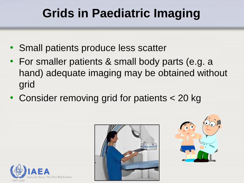
Grids in Paediatric Imaging
• Small patients produce less scatter
• For smaller patients & small body parts (e.g. a
hand) adequate imaging may be obtained without
grid
• Consider removing grid for patients < 20 kg

What does collimation do?
Collimation confines the X ray beam to an area
of the user’s choice.
A word about collimation
27
IAEA Training Course on Radiation Protection for Doctors (non-radiologists, non-cardiologists) using Fluoroscopy
L06A. Anatomy of Fluoroscopy & CT Fluoroscopy Equipment

Why is narrowing the field-of-view beneficial?
1. Reduces cancer risk to patient by reducing volume of
tissue irradiated
2. Reduces scatter radiation at image receptor to improve
image contrast
3. Reduces ambient radiation exposure to in-room
personnel
4. Reduces potential overlap of fields when beam is
reoriented
Collimation
28How to protect the patient
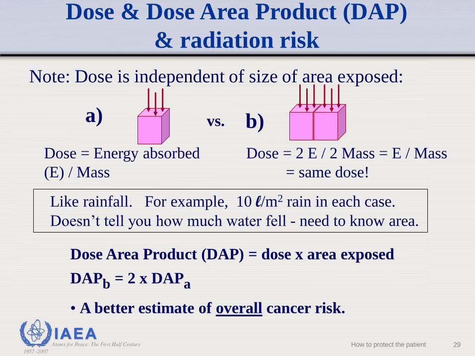
Note: Dose is independent of size of area exposed:
Dose = Energy absorbed
(E) / Mass
Dose = 2 E / 2 Mass = E / Mass
= same dose!
Like rainfall. For example, 10 l/m2 rain in each case.
Doesn’t tell you how much water fell - need to know area.
vs.a) b)
Dose Area Product (DAP) = dose x area exposed
DAPb = 2 x DAPa
• A better estimate of overall cancer risk.
Dose & Dose Area Product (DAP)
& radiation risk
29How to protect the patient

Positioning anatomy of
concern at the isocenter
permits easy
reorientation of the C-
arm but in this case the
image receptor is too
far away from the
patient’s exit surface.
This causes a high skin
entrance dose.
Projection Angle & Peak Entrance
Surface Dose
30
Imag
e Recep
tor
How to protect the patient

When isocenter
technique is
employed, move the
image intensifier as
close to the patient as
practicable to limit
dose rate at the
entrance skin surface.
Projection Angle & Peak Entrance
Surface Dose
31
Imag
e Recep
tor
It is acceptable to have
the image receptor in
contact with the patient
How to protect the patient

Lesson: Reorienting the beam distributes dose to
other skin sites and reduces risk to single skin site.
Reproduced with permission from Wagner LK, Houston, TX 2004.
Projection Angle & Peak Entrance
Surface Dose
32How to protect the patient
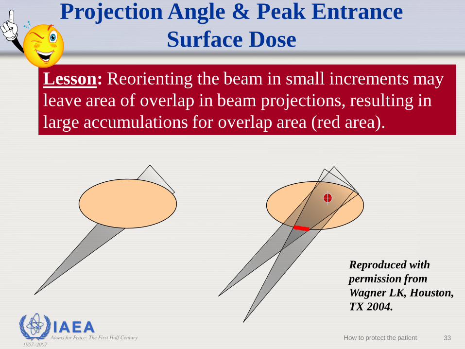
Lesson: Reorienting the beam in small increments may
leave area of overlap in beam projections, resulting in
large accumulations for overlap area (red area).
Reproduced with
permission from
Wagner LK, Houston,
TX 2004.
Projection Angle & Peak Entrance
Surface Dose
33How to protect the patient

Lesson: Reorienting the beam in small increments may leave
area of overlap in beam projections, resulting in large
accumulations for overlap area (red area).
Good collimation plus adequate rotation can emilinate this effect.
Reproduced with
permission from
Wagner LK, Houston,
TX 2004.
Projection Angle & Peak Entrance
Surface Dose
34
No over
overlap
How to protect the patient 34

Conclusion:
• Orientation of beam is usually determined and fixed by
clinical need.
• When practical, reorientation of the beam to a new skin
site can lessen risk to skin.
• Overlapping areas remaining after reorientation are still
at high risk. Good collimation reduces the overlap area.
Projection Angle & Peak Entrance
Surface Dose
35
IAEA Training Course on Radiation Protection for Doctors (non-radiologists, non-cardiologists) using Fluoroscopy
L06A. Anatomy of Fluoroscopy & CT Fluoroscopy EquipmentHow to protect the patient

INTENSIFIER
Field-of-view (FOV)
RELATIVE PATIENT ENTRANCE DOSE RATEFOR SOME UNITS
12" (32 cm) 100
9" (22 cm) 177
6" (16 cm) 400
4.5" (11 cm) 700
Dose rate dependence field-of-view or
magnification mode
36
IAEA Training Course on Radiation Protection for Doctors (non-radiologists, non-cardiologists) using Fluoroscopy
L06A. Anatomy of Fluoroscopy & CT Fluoroscopy EquipmentHow to protect the patient

• How input dose rate changes with different FOVs
depends on machine design and must be verified to
properly incorporate use into procedures.
• A typical rule is to use the least magnification
necessary for the procedure, but this does not apply
to all machines.
Dose rate dependence field-of-view or
magnification mode
37
IAEA Training Course on Radiation Protection for Doctors (non-radiologists, non-cardiologists) using Fluoroscopy
L06A. Anatomy of Fluoroscopy & CT Fluoroscopy EquipmentHow to protect the patient
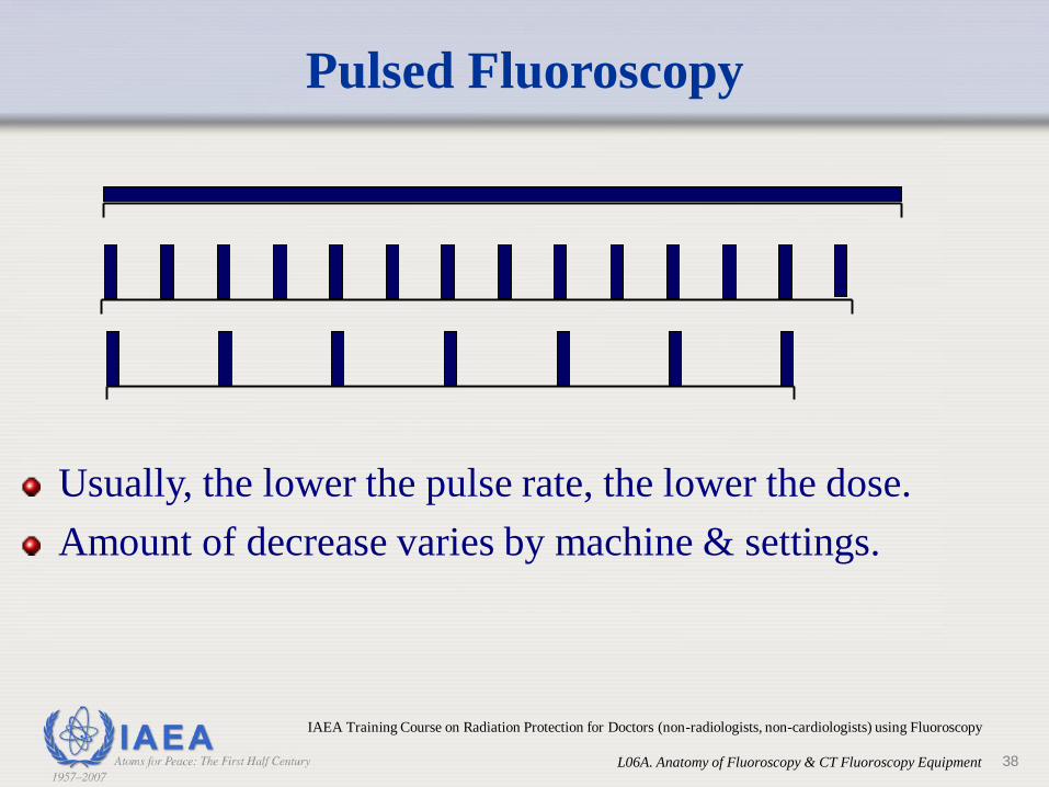
Pulsed Fluoroscopy
Usually, the lower the pulse rate, the lower the dose.
Amount of decrease varies by machine & settings.
38
IAEA Training Course on Radiation Protection for Doctors (non-radiologists, non-cardiologists) using Fluoroscopy
L06A. Anatomy of Fluoroscopy & CT Fluoroscopy Equipment
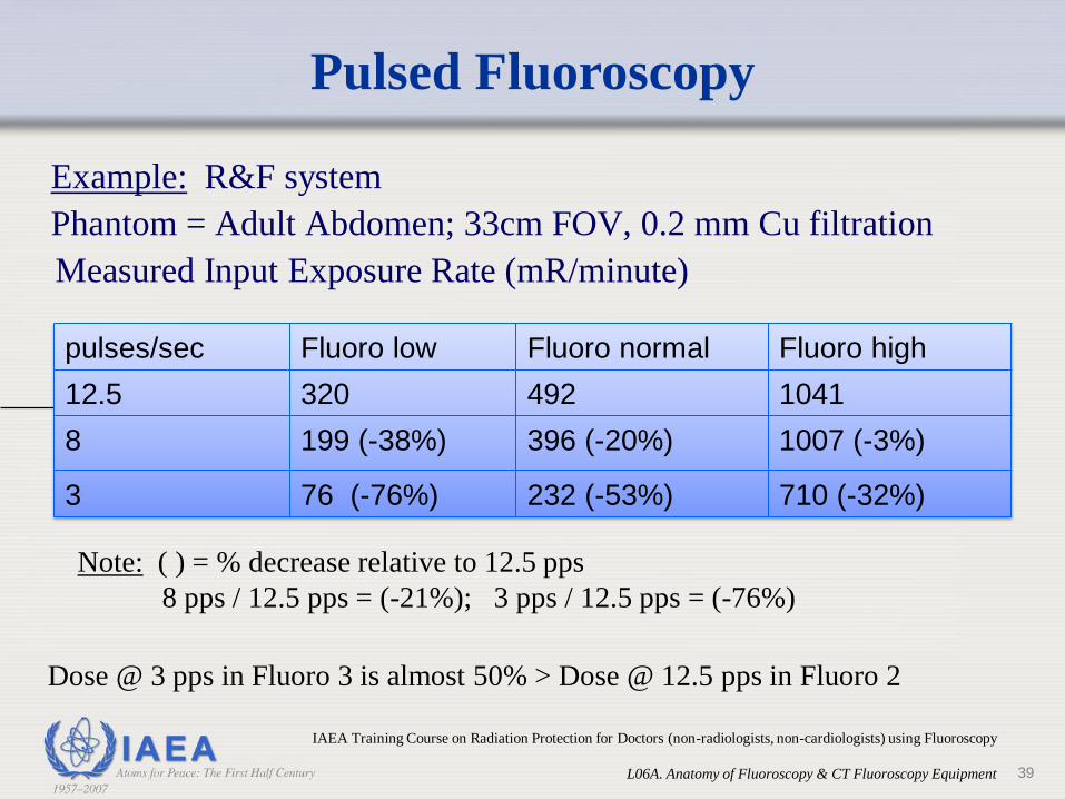
Pulsed Fluoroscopy
Example: R&F system
Phantom = Adult Abdomen; 33cm FOV, 0.2 mm Cu filtration
Measured Input Exposure Rate (mR/minute)
Note: ( ) = % decrease relative to 12.5 pps
8 pps / 12.5 pps = (-21%); 3 pps / 12.5 pps = (-76%)
Dose @ 3 pps in Fluoro 3 is almost 50% > Dose @ 12.5 pps in Fluoro 2
pulses/sec Fluoro low Fluoro normal Fluoro high
12.5 320 492 1041
8 199 (-38%) 396 (-20%) 1007 (-3%)
3 76 (-76%) 232 (-53%) 710 (-32%)
39
IAEA Training Course on Radiation Protection for Doctors (non-radiologists, non-cardiologists) using Fluoroscopy
L06A. Anatomy of Fluoroscopy & CT Fluoroscopy Equipment

Patient skin dose rate vs patient
thickness and fluoro image quality
Entrance air kerma vs Patient thickness
(Axiom Artis dFA, Fluoro Angio)
0
10
20
30
40
50
60
70
80
16 20 24 28
PMMA thickness (cm)
Entr
ance a
ir k
erm
a
(mG
y/m
in)
Fluoro -
Fluoro N
Fluoro +
R. Padovani - Optimisation of IR procedures (Oristano, 28
April 2018)
40
• Fluoroscopic dose output in modern systems is
controlled by the equipment.
• The operator can influence the way the system works by
selecting various
• imaging modes (fluoroscopy, cine)
• Image quality (low, normal, high)
• High quality Modes (boost) increase the imaging
detector input dose rates (typically x2 each step), and
hence the patient entrance dose rate increases.
Fluoroscopic X ray Output
Design of fluoroscopic equipment for
proper radiation control
41
IAEA Training Course on Radiation Protection for Doctors (non-radiologists, non-cardiologists) using Fluoroscopy
L06A. Anatomy of Fluoroscopy & CT Fluoroscopy EquipmentHow to protect the patient
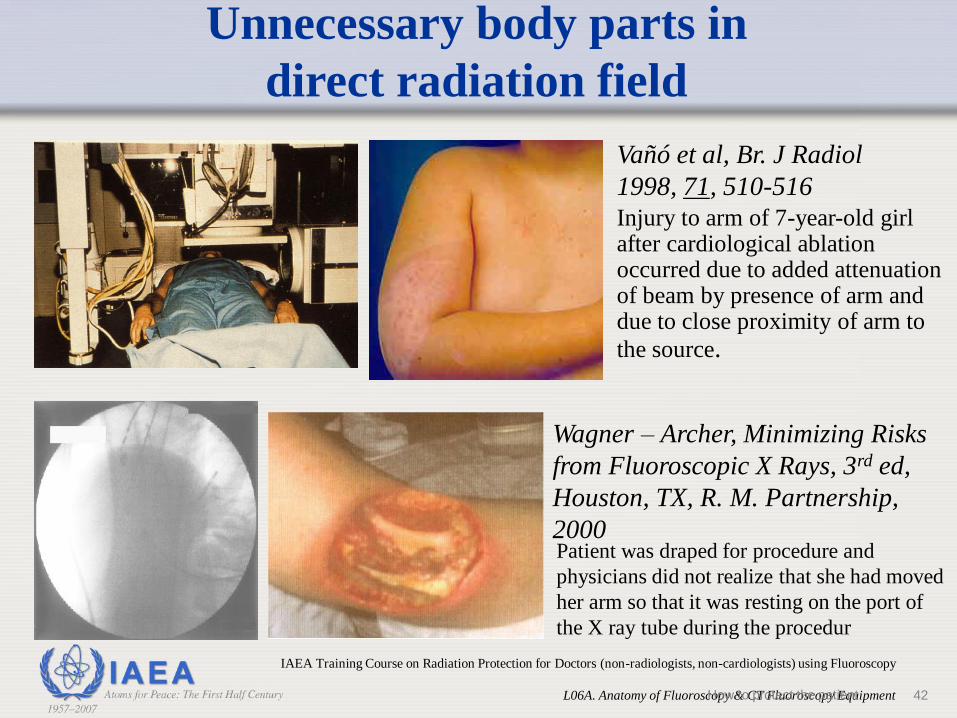
Wagner – Archer, Minimizing Risks
from Fluoroscopic X Rays, 3rd ed,
Houston, TX, R. M. Partnership,
2000
Vañó et al, Br. J Radiol
1998, 71, 510-516
Unnecessary body parts in
direct radiation field
Patient was draped for procedure and
physicians did not realize that she had moved
her arm so that it was resting on the port of
the X ray tube during the procedur
Injury to arm of 7-year-old girl after cardiological ablation occurred due to added attenuation of beam by presence of arm and due to close proximity of arm to
the source.
42
IAEA Training Course on Radiation Protection for Doctors (non-radiologists, non-cardiologists) using Fluoroscopy
L06A. Anatomy of Fluoroscopy & CT Fluoroscopy EquipmentHow to protect the patient

• Exam may involve one or more of:• Fluoroscopy
• Radiography
• Digital acquisition
• DSA, conebeamCT
• During the exam the following varies• Dose rate
• Beam size
• Beam orientation (PA, Lat., etc)
• Body Part being X rayed
Monitoring doses in complex exams
43
IAEA Training Course on Radiation Protection for Doctors (non-radiologists, non-cardiologists) using Fluoroscopy
L06A. Anatomy of Fluoroscopy & CT Fluoroscopy EquipmentHow to protect the patient

X ray Table
Dose-area product meter
Collimator
Image Intensifier
X ray Tube
2345
Reset
cGy.cm2
Monitoring doses in Complex exams –
Dose-Area Product Meters
44
IAEA Training Course on Radiation Protection for Doctors (non-radiologists, non-cardiologists) using Fluoroscopy
L06A. Anatomy of Fluoroscopy & CT Fluoroscopy EquipmentHow to protect the patient

• KAP (DAP) can be used to compare dose performance with published data
• Units Gycm2, cGycm2…
• Can be used to estimate skin dose• Via conversion tables
• Via software within X ray machine(need estimate of field size @ skin)
• Via calculation. Must estimate field size @ skin from imaging geometry (SSD & SID) &collimator size at image intensifier.
• Can be used to set action levels to prevent skin injury, but dose rather thanDAP is best for this.
SID
SSD
Monitoring patient dose
45
IAEA Training Course on Radiation Protection for Doctors (non-radiologists, non-cardiologists) using Fluoroscopy
L06A. Anatomy of Fluoroscopy & CT Fluoroscopy EquipmentHow to protect the patient
• DRL is NOT a dose limit
• DRL is the amount of radiation that in average and
under normal circumstances, one should not need to
exceed in performing an X ray procedure on an average
size patient
• Median values from a group of procedures of our
practice can be compared with national DRL to identify
practice requiring patient dose reduction (optimisation)
Diagnostic Reference Levels (DRL)
for X ray procedures
46
IAEA Training Course on Radiation Protection for Doctors (non-radiologists, non-cardiologists) using Fluoroscopy
L06A. Anatomy of Fluoroscopy & CT Fluoroscopy EquipmentHow to protect the patient

Examples
of DRLs
• UK and Ireland
• DRLs are setup
from national
patient dose
surveys
How to protect the patient 47

DRL and complexity PCI procedures
R Padovani - Complexity of IR procedures (2016) 48
Approx.
Medium =
1.5 x simple
Complex =
2.0 x simple

Example. DRL to apply to an installation
or/and to each IR professional?
• Example:
• 4 operators performing CA in the same hospital, sharing
the same mix of patients (similar complexity)
Interventionali
st
No. CA
procedur
es
KAP
(Gycm2)
Fluoro
time (min) No.
images
B 72 23.4 4.6 323
S 60 36.8 3.7 603
Z 89 58.8 3.7 818
BT 57 56.1 5.0 765
49

• Keep screening times and acquisitions to a minimum
• Use low dose settings as defaults
• Keep the X ray tube as far away from the patient as possible
• Keep the Image Intensifier close to the patient
Summary
50How to protect the patient
•Use magnification mode as little as possible
•Collimate when possible
•Use last image hold and fluoro storage if available
•Remove grid for procedures on small patients
51
Summary
How to protect the patient
• Use low pulse rate
• Use higher kVp unless it compromises image contrast
• Compare procedure fluoroscopy time and dose with published values (or national Diagnostic Reference Levels - DRL)
52
IAEA Training Course on Radiation Protection for Doctors (non-radiologists, non-cardiologists) using Fluoroscopy
L06A. Anatomy of Fluoroscopy & CT Fluoroscopy Equipment
Summary
https://rpop.iaea.org/RPOP/RPoP/Content/InformationFor/HealthProfessionals/4_InterventionalR
adiology/DiagnosticFluoroscopy.htm How to protect the patient
A final general recommendation
Be aware of the radiological protection of your
patient and you will also be improving your
own occupational protection
53
IAEA http://www.rpop.org
Radiation protection of patients
Thank you
54How to protect the patient