Embed Size (px)
Citation preview

GENERAL BUILDING ENVELOPE MECHANICAL SYSTEMS LIGHTING & ELECTRICAL POWER OTHER REQUIREMENTS
How-to Guide: Supporting Documentation
In Compliance with
2016 New York City Energy Conservation Code
GENERAL
BUILDING ENVELOPE
MECHANICAL SYSTEMS
LIGHTING & ELECTRICAL POWER
OTHER REQUIREMENTS

How-to Guide: Supporting Documentation
In Compliance with
2016 New York City Energy Conservation Code
GENERAL
BUILDING ENVELOPE
MECHANICAL SYSTEMS
LIGHTING & ELECTRICAL POWER
OTHER REQUIREMENTS
NOTE: In this How-To Guide: Supporting Documentation, selected Energy Code provisions have been generalized, summarized, rephrased, and/or highlighted. This guide is intended: 1) To
provide general guidance for the job applications seeking compliance with the 2016 NYCECC; 2) Not to replace or represent the entire 2016 NYCECC and related regulations of the City of
New York and the Department of Buildings; and 3) Not to provide complete compliance solutions for any particular type of job or work. Comprehensive mandates, applicability, exemptions,
exceptions and options will be found in the 2016 NYCECC and related regulations of the City of New York and the Department of Buildings.

GENERAL [GE - 1] BUILDING ENVELOPE MECHANICAL SYSTEMS LIGHTING & ELECTRICAL POWER OTHER REQUIREMENTS
OVERVIEW
What is Supporting Documentation?
1 RCNY §5000-01(g)
ECC 101.5.2.3
ECC 103
A Requirement to Demonstrate Compliance with NYCECC - Supporting Documentation is required for all job applications that are not exempt from the NYCECC in accordance with 1 RCNY §5000-01 (e)(2); in
other words, supporting documentation is required for all job applications submitted with PW1-Section 10 indicating that all work under the
application is in compliance with the NYCECC.
- See Quick Reference Guide: How to Demonstrate Energy Code Compliance for the full list of requirements.
- Job applications that claim to be exempt from the NYCECC must clearly state the basis for exemption in accordance with 1 RCNY §5000-01 (e)(2)
in the construction drawings, and the work scope/types on the submitted drawings and forms must validate the claim.
Essentially, Construction Documents - To be submitted to the Department of Buildings for approval.
- To inform means and methods of construction for all energy design elements in the form of technical drawings, schedules, specification notes, etc.
- To prove that all proposed energy design elements will match or exceed the requirements of the NYCECC in their quality, quantity, size, capacity,
efficiency, performance, location, configuration, composition, etc.
Must Match the Proposed Work Scope - PW1-Section 6- Work Types: Construction data (technical drawings, schedules, specification notes, etc.) must provide complete information for all
Work Types marked as proposed in PW1-Section 6.
- TR8-Section 3- Energy Code Progress Inspections: Construction data (technical drawings, schedules, specification notes, etc.) must provide
complete information for all work areas requiring Energy Code Progress Inspections marked in TR8-Section 3.
Must Support Energy Analysis - Construction documents must support the Energy Analysis reports, hence the name ‘Supporting Documentation.’ Specifically, the values and
attributes of any energy design element proposed in the construction documents must match or exceed those of the same energy design element
listed in the energy analysis (e.g., Tabular analysis, REScheck/COMcheck analysis).
- See page [GE-5] for the energy analysis methods.

GENERAL [GE - 2] BUILDING ENVELOPE MECHANICAL SYSTEMS LIGHTING & ELECTRICAL POWER OTHER REQUIREMENTS
KEY PRINCIPLES
How Should Supporting Documentation be Prepared?
1 RCNY §5000-01(g)
ECC 101.5.2.3
ECC 103
Identify a Correct Code Version to Follow
- Job applications filed on and after October 3, 2016 must comply with the 2016 NYCECC.
- Job applications filed between January 1, 2015 and October 2, 2016 must comply with the 2014 NYCECC.
- See Energy Code Version Table to identify which ECC Code version is applicable for a particular job application.
Identify Correct Code Sections to Follow - Mandatory provisions must be satisfied by all applications, whereas Prescriptive provisions must be satisfied by applications that seek to prove
compliance prescriptively.
- Applicable Code sections must be carefully identified and selected according to the job application/project type.
- For a Commercial building application, the Single chosen Code (NYCECC or ASHRAE; indicated as the Code compliance path on PW1–Section 10)
must be referenced throughout the entire set of construction documents.
2016 NYCECC Residential Buildings
Commercial Buildings w.
NYCECC as Code Compliance Path
Commercial Buildings w.
ASHRAE as Code Compliance Path
New Buildings Existing Buildings New Buildings Existing Buildings New Buildings Existing Buildings
Chapter 1 Administration v v v v v v
Chapter R2 Definitions v v
Chapter R3 General Requirements v v
Chapter R4 Residential Energy Efficiency v
Chapter R5 Existing Buildings
v
Chapter R6 Referenced Standards v v
Appendix RA Recommended Procedure 1 v
Appendix RB Solar Ready Provisions 2 v
Chapter C2 Definitions
v v
Chapter C3 General Requirements
v v
Chapter C4 Commercial Energy Efficiency
v
Chapter C5 Existing Buildings
v
Chapter C6 Referenced Standards
v v
Appendix CA ASHRAE 90.1-2013 with NYC Modifications 3
v v
Complete Code Section Title
1. Recommended Procedure For Worst-Case Testing of Atmospheric Venting Systems Under R402.4 Or R405 Conditions < 5 ACH50
2. Solar-Ready Provisions – Detached One- and Two-Family Dwellings, Multiple Single-Family Dwellings (Townhouses)
3. Modified National Standard for Buildings, Except For Low-Rise Residential Buildings
Figure GE-2.
2016 NYCECC and Applicable Job Types

GENERAL [GE - 3] BUILDING ENVELOPE MECHANICAL SYSTEMS LIGHTING & ELECTRICAL POWER OTHER REQUIREMENTS
KEY PRINCIPLES
How Should Supporting Documentation be Prepared?
1 RCNY §5000-01(g)
ECC 101.5.2.3
ECC 103
Label Energy Design Elements Consistently Among Drawings - Identification keys for all proposed energy design elements, such as wall types, window/door types, light fixture types, mechanical equipment
systems, etc., must be consistent between Supporting Documentation and Energy Analysis.
Values and Descriptions Must Match - Specifications (in values and descriptions) of energy design elements reported in Energy Analysis must be validated through Supporting
Documentation. For example, Energy-Code-relevant specifications (e.g., insulation type, R-value, U-factor, luminaire type, luminaire wattage,
equipment size, equipment efficiency, etc.) declared in the COMcheck energy analysis, but not identified in the construction documents will not be
accepted for Energy Code compliance.
- Total numbers reported in Energy Analysis must be validated through Supporting Documentation. For example, the gross values such as exterior
wall/fenestration areas, roof/floor areas, luminaire/equipment counts, area-weighted average values, etc. listed in the Tabular energy analysis
must be easily identified in the drawings, schedules, and/or diagrams provided in the construction documents.
Figure GE-3.
Sample Lighting Fixture Layout Plan (top left),
Matching Fixture Schedule (top right), and
Matching Interior Lighting COMcheck Report (bottom right)
GENERAL [GE - 4] BUILDING ENVELOPE MECHANICAL SYSTEMS LIGHTING & ELECTRICAL POWER OTHER REQUIREMENTS
KEY PRINCIPLES
How Should Supporting Documentation be Prepared?
1 RCNY §5000-01(g)
ECC 101.5.2.3
ECC 103
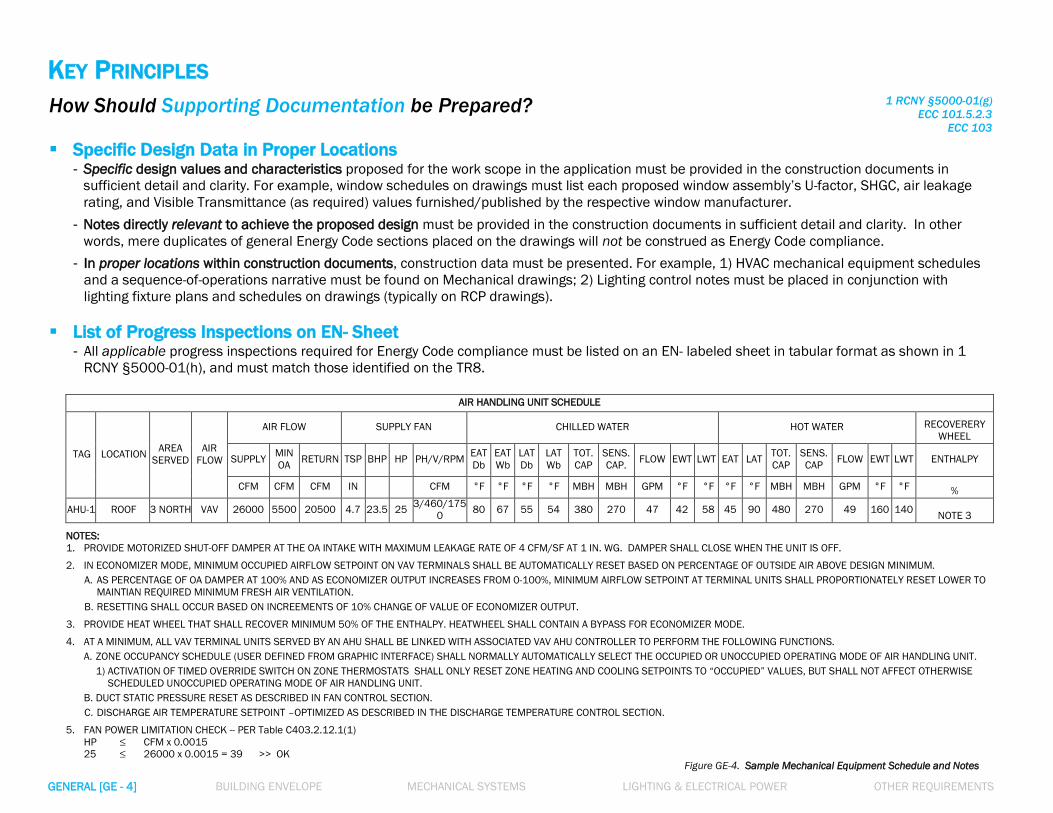
Specific Design Data in Proper Locations
- Specific design values and characteristics proposed for the work scope in the application must be provided in the construction documents in
sufficient detail and clarity. For example, window schedules on drawings must list each proposed window assembly’s U-factor, SHGC, air leakage
rating, and Visible Transmittance (as required) values furnished/published by the respective window manufacturer.
- Notes directly relevant to achieve the proposed design must be provided in the construction documents in sufficient detail and clarity. In other
words, mere duplicates of general Energy Code sections placed on the drawings will not be construed as Energy Code compliance.
- In proper locations within construction documents, construction data must be presented. For example, 1) HVAC mechanical equipment schedules
and a sequence-of-operations narrative must be found on Mechanical drawings; 2) Lighting control notes must be placed in conjunction with
lighting fixture plans and schedules on drawings (typically on RCP drawings).
List of Progress Inspections on EN- Sheet - All applicable progress inspections required for Energy Code compliance must be listed on an EN- labeled sheet in tabular format as shown in 1
RCNY §5000-01(h), and must match those identified on the TR8.
AIR HANDLING UNIT SCHEDULE
TAG LOCATION AREA
SERVED
AIR
FLOW
AIR FLOW SUPPLY FAN CHILLED WATER HOT WATER RECOVERERY
WHEEL
SUPPLY MIN
OA RETURN TSP BHP HP PH/V/RPM
EAT
Db
EAT
Wb
LAT
Db
LAT
Wb
TOT.
CAP
SENS.
CAP. FLOW EWT LWT EAT LAT
TOT.
CAP
SENS.
CAP FLOW EWT LWT ENTHALPY
CFM CFM CFM IN CFM °F °F °F °F MBH MBH GPM °F °F °F °F MBH MBH GPM °F °F %
AHU-1 ROOF 3 NORTH VAV 26000 5500 20500 4.7 23.5 25 3/460/175
0 80 67 55 54 380 270 47 42 58 45 90 480 270 49 160 140
NOTE 3
NOTES:
1. PROVIDE MOTORIZED SHUT-OFF DAMPER AT THE OA INTAKE WITH MAXIMUM LEAKAGE RATE OF 4 CFM/SF AT 1 IN. WG. DAMPER SHALL CLOSE WHEN THE UNIT IS OFF.
2. IN ECONOMIZER MODE, MINIMUM OCCUPIED AIRFLOW SETPOINT ON VAV TERMINALS SHALL BE AUTOMATICALLY RESET BASED ON PERCENTAGE OF OUTSIDE AIR ABOVE DESIGN MINIMUM.
A. AS PERCENTAGE OF OA DAMPER AT 100% AND AS ECONOMIZER OUTPUT INCREASES FROM 0-100%, MINIMUM AIRFLOW SETPOINT AT TERMINAL UNITS SHALL PROPORTIONATELY RESET LOWER TO
MAINTIAN REQUIRED MINIMUM FRESH AIR VENTILATION.
B. RESETTING SHALL OCCUR BASED ON INCREEMENTS OF 10% CHANGE OF VALUE OF ECONOMIZER OUTPUT.
3. PROVIDE HEAT WHEEL THAT SHALL RECOVER MINIMUM 50% OF THE ENTHALPY. HEATWHEEL SHALL CONTAIN A BYPASS FOR ECONOMIZER MODE.
4. AT A MINIMUM, ALL VAV TERMINAL UNITS SERVED BY AN AHU SHALL BE LINKED WITH ASSOCIATED VAV AHU CONTROLLER TO PERFORM THE FOLLOWING FUNCTIONS.
A. ZONE OCCUPANCY SCHEDULE (USER DEFINED FROM GRAPHIC INTERFACE) SHALL NORMALLY AUTOMATICALLY SELECT THE OCCUPIED OR UNOCCUPIED OPERATING MODE OF AIR HANDLING UNIT.
1) ACTIVATION OF TIMED OVERRIDE SWITCH ON ZONE THERMOSTATS SHALL ONLY RESET ZONE HEATING AND COOLING SETPOINTS TO “OCCUPIED” VALUES, BUT SHALL NOT AFFECT OTHERWISE
SCHEDULED UNOCCUPIED OPERATING MODE OF AIR HANDLING UNIT.
B. DUCT STATIC PRESSURE RESET AS DESCRIBED IN FAN CONTROL SECTION.
C. DISCHARGE AIR TEMPERATURE SETPOINT –OPTIMIZED AS DESCRIBED IN THE DISCHARGE TEMPERATURE CONTROL SECTION.
5. FAN POWER LIMITATION CHECK -- PER Table C403.2.12.1(1)
HP ≤ CFM x 0.0015
25 ≤ 26000 x 0.0015 = 39 >> OK Figure GE-4. Sample Mechanical Equipment Schedule and Notes

GENERAL [GE - 5] BUILDING ENVELOPE MECHANICAL SYSTEMS LIGHTING & ELECTRICAL POWER OTHER REQUIREMENTS
ENERGY ANALYSIS
(to demonstrate ECC Compliance in conjunction with Supporting Documentation)
Refer to Quick Reference Guide: How to Demonstrate Energy Code Compliance 1 RCNY §5000-01(f)
ECC 101.5.2.2
Figure GE-5
Energy Analysis Methods

How-to Guide: Supporting Documentation
In Compliance with
2016 New York City Energy Conservation Code
GENERAL
BUILDING ENVELOPE
MECHANICAL SYSTEMS
LIGHTING & ELECTRICAL POWER
OTHER REQUIREMENTS
NOTE: In this How-To Guide: Supporting Documentation, selected Energy Code provisions have been generalized, summarized, rephrased, and/or highlighted. This guide is intended: 1) To
provide general guidance for the job applications seeking compliance with the 2016 NYCECC; 2) Not to replace or represent the entire 2016 NYCECC and related regulations of the City of
New York and the Department of Buildings; and 3) Not to provide complete compliance solutions for any particular type of job or work. Comprehensive mandates, applicability, exemptions,
exceptions and options will be found in the 2016 NYCECC and related regulations of the City of New York and the Department of Buildings.

GENERAL BUILDING ENVELOPE [BE - 1] MECHANICAL SYSTEMS LIGHTING & ELECTRICAL POWER OTHER REQUIREMENTS
NOTE: One common error in the U-
factor calculation is misrepresenting
thermal values of assembly layers
(e.g., face brick, gypsum board, air
films, etc.) from unapproved sources.
OPAQUE ENVELOPE ASSEMBLIES Minimum R-value
- For each building envelope type (e.g., roof, above-grade/below-grade walls, floors over unconditioned space, etc.), its section detail
must indicate that the R-value of the insulation meets or exceeds the minimum allowed R-value prescribed for the envelope type
(e.g., R-values shown in Table C402.1.3).
- Specifically, in the assembly details, clearly call out each of the proposed insulation type, thickness and the manufacturer-
published R-value to satisfy the thermal requirements for the envelope assembly type.
R402.3
C402.1.3
5.5.3
Maximum U-factor
- Alternatively, it must be demonstrated that the proposed assembly’s calculated U-factor value does not exceed the maximum
allowed U-factor value prescribed for the envelope type (e.g., U-factors shown in Table C402.1.4).
- In the calculation of the overall assembly’s U-factor, thermal performance values (e.g., R-value, U-factor, C-factor, etc.)
corresponding to the assembly detail must be quoted from Appendix A of ASHRAE 90.1-2013. U-factor calculation methods must
also be in accordance with Appendix A.
R402.3
C402.1.4
5.5.3
Figure BE-1. Sample Wall Assembly & Area-Weighted U-factor Calculation

GENERAL BUILDING ENVELOPE [BE - 2] MECHANICAL SYSTEMS LIGHTING & ELECTRICAL POWER OTHER REQUIREMENTS
Figure BE-2. Sample Windows & Doors Schedule
DOORS & WINDOWS – FENESTRATION IN THE ENVELOPE U-factor and SHGC values
- For each fenestration type (e.g., fixed/operable window, skylight, exterior door, storefront, etc.), U-factor and Solar Heat Gain
Coefficient (SHGC) values must be specified in the window/door schedule on drawings and must not exceed the maximum allowed
values in the fenestration requirements (e.g., Table C402.4).
- Next to the U-factor and SHGC values specified in the schedule, provide the fenestration assembly manufacturer’s information (e.g.,
‘ABC Windows/def 9000 series, or Approved equal’) that will satisfy the U-factor and SHGC requirements.
R402.3
C402.4
5.5.4.3
5.5.4.4
Air Leakage Rate and Visible Transmittance (VT)
- The window/door schedule on drawings must specify the air leakage rate of each proposed fenestration assembly type to
demonstrate that the air leakage of fenestration assemblies do not exceed the maximum allowed leakage rate.
- Where required, the window/door schedule must identify Visible Transmittance (VT) of the proposed glazed fenestration
products to meet the provisions in the applicable Code sections.
R402.4/C402.5.2
5.4.3.2
R303.1.3/C303.1.3
C402.4, C405.2.3
5.5.4.6
WINDOW & DOOR SCHEDULE
TAG TYPE MATERIAL NOMINAL DIM.
(W X H) MANUFACTURER - MODEL NO.
ASSEMBLY
U-FACTOR SHGC VT
AIR LEAKAGE
RATE
(CFM/SF)
W1 FIXED ANNO.
ALUMINUM 7'-0" X 7'-0"
ABC WINDOWS - D999 SERIES
OR APPROVED EQUAL 0.33 0.38 0.51 0.16
W1A FIXED & CASEMENT ANNO.
ALUMINUM 7'-0" X 7'-0"
ABC WINDOWS - D999 SERIES
OR APPROVED EQUAL 0.35 0.39 0.51 0.18
W2 CASEMENT ANNO.
ALUMINUM 4'-6" X 2'-3"
ABC WINDOWS -EF00 SERIES
OR APPROVED EQUAL 0.42 0.39 0.51 0.18
SW1 SKYLIGHT ANNO.
ALUMINUM 2'-10" X 5'-2"
SKL CORP. - GHT000 SERIES
OR APPROVED EQUAL 0.40 0.38 0.5 0.18
W5 STOREFRONT - FIXED
GLAZING
ANNO.
ALUMINUM
VARIES; SEE A-301 ~305
FOR LOCATIONS & DIM.
GLD CO. - STR #Z111 OR
APPROVED EQUAL 0.36 0.38 0.53 0.05
D1
STOREFRONT -
ENTRANCE GLASS
DOOR
GLASS/
METAL 3'-0" X 7'-6"
GLD CO. - STR #Z111 OR
APPROVED EQUAL 0.60 0.38 0.53 0.18
D2 OPAQUE SWINGING
DOOR METAL 3'-0" X 7'-0"
OPQ COMPANY RST-#22-33
OR APPROVED EQUAL 0.55 N/A N/A 0.18
Fenestration U-factor values must be the ‘whole assembly’ U-factor, instead of ‘center-of-glass’ U-factor, and must be furnished by the manufacturer.
Differentiate Fixed and Operable windows’ U-factor values in the window schedule where required, as the Code-prescribed maximum U-factors for Fixed
and Operable windows may vary depending on the referenced Code.

GENERAL BUILDING ENVELOPE [BE - 3] MECHANICAL SYSTEMS LIGHTING & ELECTRICAL POWER OTHER REQUIREMENTS
FENESTRATION AREA Maximum Vertical Fenestration Area (when following ECC)
- Maximum vertical fenestration area (excl. opaque doors & spandrel panels): 30% of the gross above-grade wall area
- Maximum vertical fenestration area (excl. opaque doors & spandrel panels): 40% of the gross above-grade wall area with
certain requirements
See Section C402.4.1.1 for all requirements. << (e.g., daylight responsive controls).
- The percentage value of the total vertical fenestration area of job applications must be computed and noted on an EN- labeled drawing
in conjunction with building elevations or elevation diagrams.
- When vertical fenestration area > 40%: ASHRAE must be chosen as Code Compliance Path; ECC does not allow > 40%.
(Either COMcheck or Energy Modeling may be used for the energy analysis.)
C402.4.1
C502.2.1
Maximum Vertical Fenestration Area (when following ASHRAE)
- Maximum vertical fenestration area (excluding opaque doors and spandrel panels): 40% of the gross wall area
- When vertical fenestration area > 40%, Energy Code compliance may be demonstrated through either COMcheck (with envelope
tradeoff) or Energy Modeling (total building performance) energy analysis method.
5.5.4.2.1
Skylight Fenestration Area (when following ECC)
- Maximum skylight fenestration area: 3% of the gross roof area
- Maximum skylight fenestration area with daylight responsive controls: 5% of the gross roof area
When > 5%: ASHRAE must be chosen.
- Minimum skylight fenestration area requirement: Minimum 3% of the gross roof area, or Minimum 1% ‘Skylight Effective Aperture’ >> See Section C402.4.2 for the spaces where minimum skylight fenestration area is required. >> For ‘Skylight Effective Aperture,’ refer to Equation 4-4 in Section C402.4.2.
C402.4.1
C402.4.2
Skylight Fenestration Area (when following ASHRAE)
- Maximum skylight fenestration area: 3% of the gross roof area
- Maximum skylight fenestration area with certain requirements: 6% of the gross roof area
>> See Section 5.5.4.2.2 for all requirements. When > 6%: Either COMcheck (with envelope tradeoff)
or Energy Modeling may be used to demonstrate compliance.
- Minimum skylight fenestration area requirement:
Minimum 3% of the gross roof area, or Minimum 1% ‘Skylight Effective Aperture’
>> See Section 5.5.4.2.3 for the spaces where minimum skylight fenestration area is required.
5.5.4.2.2
5.5.4.2.3

GENERAL BUILDING ENVELOPE [BE - 4] MECHANICAL SYSTEMS LIGHTING & ELECTRICAL POWER OTHER REQUIREMENTS
AIR BARRIER Continuous Air Barrier
To ensure air barrier continuity in the building thermal envelope, drawings must specify applicable air barrier construction methods
(Section C402.5.1.1), and indicate that the building envelope is composed of 1) building materials not exceeding maximum allowed
air permeability (Section C402.5.1.2.1), and/or 2) assemblies not exceeding allowed maximum air leakage (Section C402.5.1.2.2).
C402.5.1
5.4.3.1.2
5.4.3.1.3
Openings in the Building Envelope
Drawings must identify specific construction methods, configuration, devices and/or performance standards to limit air leakage in
particular envelope areas including, but not limited to, the following: C402.5/5.4.3.1.1
1) Fenestration and doors: Maximum allowed air leakage.
2) Outdoor air intakes and exhaust openings: Shutoff dampers – Motorized unless gravity dampers are allowed.
3) Doors/Access Openings to shafts, chutes, vents, stairways and elevator lobbies: Gasketting, weatherstripping, and sealing.
4) Loading dock: Weatherseals to restrict infiltration.
5) Vestibules: Plan configuration and self-closing devices on doors.
6) Recessed lighting: Luminaires installed in building envelope to be: a) IC-rated, b) Labeled with the Code-prescribed maximum
air leakage rate, and c) Sealed with gasket or caulk.
C402.5.2/5.4.3.2
C402.5.5/6.4.3.4
C402.5.4
C402.5.6/5.4.3.3
C402.5.7/5.4.3.4
C402.5.8/5.4.3.1.1
a) Code-Compliant Plan b) Non-Compliant Plan c) Acceptable Plan with specific notes requiring future compliance
Figure BE-4.
Sample Vestibule Plan Configurations

GENERAL BUILDING ENVELOPE [BE - 5] MECHANICAL SYSTEMS LIGHTING & ELECTRICAL POWER OTHER REQUIREMENTS
AIR LEAKAGE TESTING & AIR BARRIER CONTINUITY PLAN Whole Building Air Leakage Testing
- For new Residential buildings, mandatory air leakage testing must be specified to ensure the air leakage rate does not exceed 3
air changes per hour (3 ACH) at 50 Pascals.
- For Residential buildings with 2 to 7 dwelling units within the building envelope, and with 8 or more dwelling units within the
building envelope, drawings may identify alternate testing procedures of sample “testing unit” verification methods as specified in
the Code.
- For new Commercial buildings 25,000 to 49,999 sf in the conditioned space floor area, and 75 ft or less in height, mandatory air
leakage testing must be specified to ensure the air leakage rate does not exceed 0.4 cfm/ft2 of envelope area at 75 Pascals.
R402.4.1.2
R402.4.1.3
C402.5.1.3
5.4.3.5
Air Barrier Continuity Plan
- For new Commercial buildings 50,000 sf or greater in the conditioned space floor area, an Air Barrier Continuity Plan must be
prepared and implemented.
- The Air Barrier Continuity Plan must specify (1) List of typical joint and seam conditions, (2) Testing method options for each, (3)
Sampling rates of test, (4) Quality control process in test, and (5) Guidelines for test reports and final certificates.
C402.5.1.3
5.4.3.5
Figure BE-5. Blower door installed for air leakage testing at a construction site
Source: energycodes.gov/resource-center/resource-guides
Meeting the Air Leakage Requirements of the 2012 IECC is a general air leakage
reference guide provided by the U.S. Department of Energy: Building Energy Codes
Program.
Please use the guide in the link for general reference purposes only as 2016 NYCECC
is in parallel with 2015 IECC, a more recent IECC Code version.

GENERAL BUILDING ENVELOPE [BE - 6] MECHANICAL SYSTEMS LIGHTING & ELECTRICAL POWER OTHER REQUIREMENTS
THERMAL BRIDGING IN BUILDING ENVELOPE Address the Thermal Bridging!
- Drawings must address all thermal-bridging-prone areas in the building envelope either by specifying supplemental insulation
materials in such areas (prescriptive path), or by reporting the inferior thermal resistance values of the areas individually in the
energy analysis (envelope trade-off path).
- Thermal bridging commonly occurs in floor slab/joist edges, floor and balcony connections, slab-on-grade conditions, and roof and
wall connection areas among others.
- Job applications seeking to meet the building envelope requirements prescriptively must prove that each of the thermal-bridging-
prone areas meet the minimum insulation requirement.
R402
C402
Trade-Offs in the Envelope for Residential Buildings – Total UA Alternative
- Alternatively, for Residential buildings, assembly details for building envelope components must demonstrate that:
Total building thermal envelope UA < Total UA resulting from the Code-prescriptive U-factors (Sum of Assembly area x its U-factor) (Sum of Assembly area x Code U-factor value for the assembly type)
- This could be verified by the REScheck envelope energy analysis by entering all building envelope components of varying thermal
resistance values.
R402.1.5
Trade-Offs in the Envelope for Commercial Buildings – Component Performance Alternative
- Alternatively, for Commercial buildings, assembly details for building envelope components must demonstrate the compliance with
insulation requirements by satisfying the formula in Section C402.1.5.
- Compliance could be verified with the COMcheck envelope energy analysis by entering all building envelope components’ varying
thermal values, as this Alternative method has been built into the COMcheck software.
C402.1.5
5.6.1.1
Figure BE-6.
Sample Slab Edge Detail &
Matching Envelope COMcheck Report

GENERAL BUILDING ENVELOPE [BE - 7] MECHANICAL SYSTEMS LIGHTING & ELECTRICAL POWER OTHER REQUIREMENTS
THERMAL BRIDGING IN BUILDING ENVELOPE
Figure BE-7.
Sample Balcony Edge Details &
Matching Envelope COMcheck Reports

GENERAL BUILDING ENVELOPE [BE - 8] MECHANICAL SYSTEMS LIGHTING & ELECTRICAL POWER OTHER REQUIREMENTS
EQUIPMENT PENETRATIONS IN BUILDING ENVELOPE Calculation of Equipment Penetration Areas
When mechanical equipment listed in Table C403.2.3(3) or Table 6.8.1-4 are proposed in a New Commercial building application:
- Drawings must identify the calculated total area of the equipment penetrations in the opaque above-grade walls by the supporting
diagrammatic building elevations.
- Drawings must also identify the percentage of the total equipment penetration area out of the total opaque above-grade wall area.
C402.1.4.2
5.5.3
U-factor 0.5 for Penetration Areas > 1% of Opaque Walls
- If the total area of penetrations from mechanical equipment specified above exceeds 1% of the total opaque above-grade wall
area, the equipment penetration area must be identified as a separate wall assembly with a default U-factor of 0.5.
- Accordingly, in the envelope energy analysis (e.g., Component performance alternative calculation, COMcheck, or Energy Modeling)
the total equipment penetration area must be entered as a separate exterior wall type of proposed U-factor 0.5 and budget U-
factor identical to the surrounding wall.
C402.1.4.2
C402.1.5
5.6.1.1
Figure BE-8.
Sample Envelope COMcheck report with
Equipment Penetration Area entered as a separate opaque wall type

GENERAL BUILDING ENVELOPE [BE - 9] MECHANICAL SYSTEMS LIGHTING & ELECTRICAL POWER OTHER REQUIREMENTS
FUEL-BURNING APPLIANCES Thermally Isolated and Insulated Rooms
When open combustion air ducts provide combustion air to open combustion fuel-burning appliances (e.g., natural draft boilers or
furnaces) in a room, the room must be thermally isolated from the building it serves, and sealed and insulated to meet the
requirements of Table R402.1.2, Table C402.1.3 or C402.1.4.
R402.4.4
C402.5.3
Direct Vent Appliances
If the fuel-burning appliances are to be located in a room within the building thermal envelope, the appliances must be identified as
direct vent appliances with both intake and exhaust pipes installed continuous to the outside.
R402.4.4
C402.5.3
Fireplaces with Tight-fitting Doors or Dampers
Fireplaces or fireplace units that are designed to allow an open burn must be specified with tight-fitting flue dampers or tight-fitting
doors labeled with applicable Code-required UL listings.
R402.4.2
C402.2.7
Figure BE-9. A direct-vent sealed-combustion furnace with dedicated pipes for combustion air and exhaust installed continuous to the outside
Source: basc.pnnl.gov/images
GENERAL BUILDING ENVELOPE [BE - 10] MECHANICAL SYSTEMS LIGHTING & ELECTRICAL POWER OTHER REQUIREMENTS
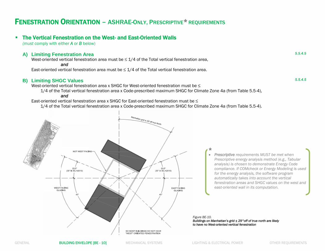
FENESTRATION ORIENTATION – ASHRAE-ONLY, PRESCRIPTIVE* REQUIREMENTS
The Vertical Fenestration on the West- and East-Oriented Walls
(must comply with either A or B below)
A) Limiting Fenestration Area 5.5.4.5
West-oriented vertical fenestration area must be ≤ 1/4 of the Total vertical fenestration area,
and
East-oriented vertical fenestration area must be ≤ 1/4 of the Total vertical fenestration area.
B) Limiting SHGC Values 5.5.4.5
West-oriented vertical fenestration area x SHGC for West-oriented fenestration must be ≤
1/4 of the Total vertical fenestration area x Code-prescribed maximum SHGC for Climate Zone 4a (from Table 5.5-4),
and
East-oriented vertical fenestration area x SHGC for East-oriented fenestration must be ≤
1/4 of the Total vertical fenestration area x Code-prescribed maximum SHGC for Climate Zone 4a (from Table 5.5-4).
Prescriptive requirements MUST be met when
Prescriptive energy analysis method (e.g., Tabular
analysis) is chosen to demonstrate Energy Code
compliance. If COMcheck or Energy Modeling is used
for the energy analysis, the software program
automatically takes into account the vertical
fenestration areas and SHGC values on the west and
east-oriented wall in its computation.
*
Figure BE-10.
Buildings on Manhattan’s grid ± 29°off of true north are likely
to have no West-oriented vertical fenestration

GENERAL BUILDING ENVELOPE [BE - 11] MECHANICAL SYSTEMS LIGHTING & ELECTRICAL POWER OTHER REQUIREMENTS
RESIDENTIAL BUILDING ENVELOPE Blown or Sprayed Roof/Ceiling Insulation
- The thickness of blown-in or sprayed roof/ceiling insulation (fiberglass or cellulose) in the attic must be indicated on markers for
every 300 sf.
- The markers must indicate minimum initial installed thickness with numbers of a minimum of 1 inch in height.
R303.1.1.1
Protection of Exposed Foundation Insulation
Rigid, opaque and weather-resistant protective coverings must be applied to protect the insulation over the exterior of basement
walls, crawl space walls and the perimeter of slab-on-grade floors.
R303.2.1
Slab-on-Grade Floor Insulation at the Perimeter
- Slab-on-grade floors with a floor surface < 12” below grade must be insulated at the perimeter with minimum R-10 for Unheated
slab, and minimum R-15 for Heated slab.
- The insulation must be extended downward or horizontally (as shown in the Figures below) a minimum of 4’ for Climate Zone 4A.
- Insulation extending away from the building must be protected by pavement or by minimum 10” of soil.
R402.2.10
Insulation at Tenant Separation Walls Fire-separated walls between dwelling units in two-family houses or townhouses must be insulated at a minimum R-value of R-10.
R402.4.6
Figure BE-11.b.
Slab Insulation Methods
Source: basc.pnnl.gov/images
Figure BE-11.a.
Protection of Insulation Over the Grade Beam
Source: basc.pnnl.gov/images

GENERAL BUILDING ENVELOPE [BE - 12] MECHANICAL SYSTEMS LIGHTING & ELECTRICAL POWER OTHER REQUIREMENTS
RESIDENTIAL BUILDING ENVELOPE
Insulation in Ceilings
- Ceiling with Attic Spaces: Minimum R-49; or Uncompressed R-38 covering 100% of ceiling and extended over the wall top plate at
the eaves (See Figures below).
- Ceiling without Attic Spaces: When installation of required minimum R-49 insulation in 100% of the ceiling is unachievable, R-30
insulation is allowed for a maximum 500 sf or maximum 20% of the total insulated ceiling area, whichever is less. If partial R-30
insulation is proposed, provide roof area calculations with roof plan diagrams.
R402.2.1
R402.2.2
Access Hatches and Doors
Access doors to unconditioned spaces such as attics and crawl spaces must be weatherstripped and insulated to a level equivalent
to the insulation on the surrounding surfaces (e.g., adjacent ceiling surface).
R402.2.4
Sunroom Insulation and Fenestration
- Sunrooms enclosing conditioned space must meet the Residential building envelope insulation and fenestration requirements.
- Sunrooms with thermal isolation and enclosing conditioned space must meet the following insulation and fenestration
requirements:
Ceiling Insulation: Min. R-19
Wall Insulation: Min. R-13
Vertical Fenestration: Max. U-0.45
Skylight: Max. U-0.70
- Conditioned space with thermal isolation must be controlled as a separate zone for heating and cooling, or conditioned by
separate equipment.
R402.2.13
R402.3.5
Figure BE-12.a.
Uncompressed Insulation Extended to Cover Wall Top Plate
Source: basc.pnnl.gov/images
Figure BE-12.b.
Access Hatch Properly Insulated
Source: basc.pnnl.gov/images

How-to Guide: Supporting Documentation
In Compliance with
2016 New York City Energy Conservation Code
GENERAL
BUILDING ENVELOPE
MECHANICAL SYSTEMS
LIGHTING & ELECTRICAL POWER
OTHER REQUIREMENTS
NOTE: In this How-To Guide: Supporting Documentation, selected Energy Code provisions have been generalized, summarized, rephrased, and/or highlighted. This guide is intended: 1) To
provide general guidance for the job applications seeking compliance with the 2016 NYCECC; 2) Not to replace or represent the entire 2016 NYCECC and related regulations of the City of
New York and the Department of Buildings; and 3) Not to provide complete compliance solutions for any particular type of job or work. Comprehensive mandates, applicability, exemptions,
exceptions and options will be found in the 2016 NYCECC and related regulations of the City of New York and the Department of Buildings.

GENERAL BUILDING ENVELOPE MECHANICAL SYSTEMS [MS - 1] LIGHTING & ELECTRICAL POWER OTHER REQUIREMENTS
For definitions of
“Residential Building” and
“Commercial Building,” refer
to R202 & C202.
OPTIMAL EQUIPMENT SIZE
Residential Buildings
- ACCA Manual J: Heating and Cooling equipment of a Residential job application must be sized in accordance with ACCA Manual S
based on building loads calculated per ACCA Manual J, or other approved calculation methodologies.
- Sizing Statement: The drawings must include a statement indicating the total Heating and Cooling design loads have been
determined as such.
- Minimum Efficiency: New or replacement heating and cooling equipment must meet or exceed the minimum efficiency rating
required by Federal law.
R403.7
Commercial Buildings
- ANSI/ASHRAE/ACCA Standard 183: Design loads associated with Heating, Ventilating and Air Conditioning (HVAC) of a Commercial
job application must be determined in accordance with ANSI/ASHRAE/ACCA Standard 183, or by an approved equivalent
computational method.
- Sizing Statement: The drawings, preferably in an EN- labeled sheet, must include a statement indicating the total HVAC design
loads have been determined as such.
- Design loads and System Commissioning: Total HVAC design loads combined with Service Water Heating loads of a job application
largely dictate whether System Commissioning (per Section C408 and Section 6.7.2.4) on the job is required or not. Refer to [OR-8]
for the detailed requirements for System Commissioning.
C403.2.1
C403.2.2
6.4.2.1
Figure MS-1. Sample Sizing Statement

GENERAL BUILDING ENVELOPE MECHANICAL SYSTEMS [MS - 2] LIGHTING & ELECTRICAL POWER OTHER REQUIREMENTS
Efficiency value of individual equipment should be listed in the same measurement
unit prescribed in the corresponding efficiency requirements table in the Code.
MINIMUM EQUIPMENT EFFICIENCY/PERFORMANCE
Complete Equipment Specifications
For all proposed HVAC and Service Water Heating (SWH) equipment, the equipment schedule on construction drawings must clearly
list the equipment efficiency or performance rating along with the type, size, capacity, and fuel type of all equipment, and any
additional specifications pertaining to the energy use of the equipment. For all Energy-Code-regulated equipment, their rated
efficiency/performance ratings identified in the equipment schedule must meet or exceed the corresponding Code-prescribed value.
R403.7
C403.2.3
C404.2
6.4.1
Values on Construction Drawings First, and then on Energy Analysis
Values and descriptions for HVAC and SWH equipment reported on Energy Analysis (on EN- labeled sheets) must be quoted
from those in the equipment schedules and specifications on the relevant construction drawings–e.g., M- , or P- labeled
drawings.
1 RCNY §5000-01
(f),(g)
Figure MS-2. Sample Mechanical Equipment Schedules & Matching
Mechanical COMcheck Report
GENERAL BUILDING ENVELOPE MECHANICAL SYSTEMS [MS - 3] LIGHTING & ELECTRICAL POWER OTHER REQUIREMENTS
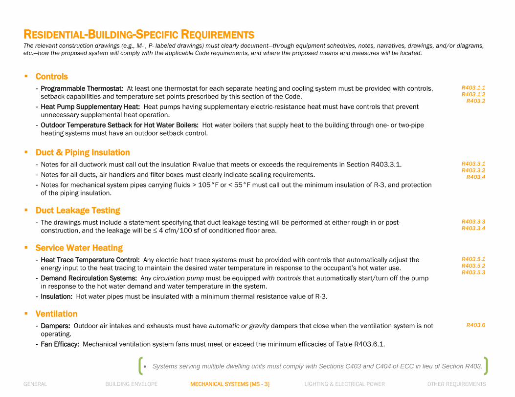
Systems serving multiple dwelling units must comply with Sections C403 and C404 of ECC in lieu of Section R403.
RESIDENTIAL-BUILDING-SPECIFIC REQUIREMENTS The relevant construction drawings (e.g., M- , P- labeled drawings) must clearly document—through equipment schedules, notes, narratives, drawings, and/or diagrams,
etc.—how the proposed system will comply with the applicable Code requirements, and where the proposed means and measures will be located.
Controls
- Programmable Thermostat: At least one thermostat for each separate heating and cooling system must be provided with controls,
setback capabilities and temperature set points prescribed by this section of the Code.
- Heat Pump Supplementary Heat: Heat pumps having supplementary electric-resistance heat must have controls that prevent
unnecessary supplemental heat operation.
- Outdoor Temperature Setback for Hot Water Boilers: Hot water boilers that supply heat to the building through one- or two-pipe
heating systems must have an outdoor setback control.
R403.1.1
R403.1.2
R403.2
Duct & Piping Insulation
- Notes for all ductwork must call out the insulation R-value that meets or exceeds the requirements in Section R403.3.1.
- Notes for all ducts, air handlers and filter boxes must clearly indicate sealing requirements.
- Notes for mechanical system pipes carrying fluids > 105°F or < 55°F must call out the minimum insulation of R-3, and protection
of the piping insulation.
R403.3.1
R403.3.2
R403.4
Duct Leakage Testing
- The drawings must include a statement specifying that duct leakage testing will be performed at either rough-in or post-
construction, and the leakage will be ≤ 4 cfm/100 sf of conditioned floor area.
R403.3.3
R403.3.4
Service Water Heating
- Heat Trace Temperature Control: Any electric heat trace systems must be provided with controls that automatically adjust the
energy input to the heat tracing to maintain the desired water temperature in response to the occupant’s hot water use.
- Demand Recirculation Systems: Any circulation pump must be equipped with controls that automatically start/turn off the pump
in response to the hot water demand and water temperature in the system.
- Insulation: Hot water pipes must be insulated with a minimum thermal resistance value of R-3.
R403.5.1
R403.5.2
R403.5.3
Ventilation
- Dampers: Outdoor air intakes and exhausts must have automatic or gravity dampers that close when the ventilation system is not
operating.
- Fan Efficacy: Mechanical ventilation system fans must meet or exceed the minimum efficacies of Table R403.6.1.
R403.6

GENERAL BUILDING ENVELOPE MECHANICAL SYSTEMS [MS - 4] LIGHTING & ELECTRICAL POWER OTHER REQUIREMENTS
HVAC SYSTEM CONTROLS The relevant construction drawings (e.g., M- , P- labeled drawings) must clearly document—through equipment schedules, notes, narratives, drawings, and/or diagrams,
etc.—how the proposed system will comply with the applicable Code requirements, and where the proposed means and measures will be located.
Thermostatic Controls
- All mandatory thermostatic controls applicable to the proposed system must be specified on drawings.
- The required controls include:
1) Heat pump supplementary heat controls
2) Minimum 5°F Deadband
3) Setpoint overlap restriction.
Note that many programmable thermostats meet this requirement.
C403.2.4.1
6.4.3.1
6.4.3.2
Off-Hour Controls
Thermostatic setback controls that are controlled by either an automatic time clock or programmable control system must be
provided in each zone.
C403.2.4.2
6.4.3.3
Narratives on Operations and Controls
A narrative must be provided for each mandatory control system describing its function and operation and specifying proper
setpoints of equipment and controls.
1 RCNY §5000-01 (g)(2)
Figure MS-4.
Sample Deadband Control Setup

GENERAL BUILDING ENVELOPE MECHANICAL SYSTEMS [MS - 5] LIGHTING & ELECTRICAL POWER OTHER REQUIREMENTS
NOTE: The indoor unit capacity for split systems and VRF systems should be used to determine whether an economizer is required.
ECONOMIZERS The relevant construction drawings (e.g., M- , P- labeled drawings) must clearly document—through equipment schedules, notes, narratives, drawings, and/or diagrams,
etc.—how the proposed system will comply with the applicable Code requirements, and where the proposed means and measures will be located.
Requirement for Each Cooling System
- Most commercial buildings have spaces that need cooling all year long. If it is colder outside than inside, economizers provide
“free cooling” by bringing in the outdoor air to cool the space in lieu of activating mechanical cooling equipment.
- Each cooling system with a capacity ≥ 54,000 Btu/h and operating 20 hours or more per week must be equipped with air or water
economizer, with some exceptions.
- Even if each cooling system meets an exception and doesn’t require an economizer, out of the total fan-cooling systems in a
building, only the greater of 300,000 Btu/h or 20% of the total supply capacity of all fan-cooling units, are allowed to be without an
economizer - only when following NYCECC.
C403.3
6.5.1
High-Efficiency Exemption
Cooling systems that are 42% more efficient than the minimum efficiency requirements are exempt from providing economizers –
only when following ASHRAE.
Table 6.5.1-3
Cooling Stage Requirements
Cooling systems with economizers are required to have two-, three- or four-stage cooling, depending on the size of the cooling
system. The economizers are required to provide partial cooling even if the outdoor air is not cool enough to satisfy the entire cooling
load.
C403.3.1
High-Limit Shutoff
Economizers in lieu of mechanical cooling can save energy significantly when the outdoor air is cool and has low humidity. The Code
sets the temperature and enthalpy limits when economizers are to shut off; these high-limit shutoffs must be noted in the
construction documents.
C403.3.3.3
6.5.1.1.3
Economizer Fault Detection and Diagnostics (FDD)
Systems equipped with an economizer must include a fault detection and diagnostics (FDD) system equipped with specific sensors
that detect and reports faults.
C403.2.4.7

GENERAL BUILDING ENVELOPE MECHANICAL SYSTEMS [MS - 6] LIGHTING & ELECTRICAL POWER OTHER REQUIREMENTS
VENTILATION The relevant construction drawings (e.g., M- , P- labeled drawings) must clearly document—through equipment schedules, notes, narratives, drawings, and/or diagrams,
etc.—how the proposed system will comply with the applicable Code requirements, and where the proposed means and measures will be located.
Demand Controlled Ventilation (DCV)
For spaces larger than 500 sf and with an average occupant load of at least 25 people/1,000 sf of floor area, demand control
ventilation (DCV) must be specified. For the average occupant load, Table 403.3 of NYC Mechanical Code must be referenced. See
figure below.
C403.2.6.1
6.4.3.8
Energy Recovery Ventilation Systems (ERV)
- Fan systems operating ≥ 8,000 hours/year with 10% or more of the design supply airflow coming from outdoor air are required to
have energy recovery ventilators (ERV).
- For fan systems operating < 8,000 hours/year, energy recovery systems may be required depending on the design supply airflow
rate.
- The ERV must have minimum of 50% total (sensible and latent) recovery effectiveness and controls that communicate with
economizer operation and are documented in the equipment schedule and controls notes.
- In most cases, when multiple exhaust risers are within 30 feet of a supply air unit, an ERV is required.
C403.2.7
6.5.6.1
Figure MS-6.
Excerpt from Table 403.3 of NYC Mechanical Code Chapter 4

GENERAL BUILDING ENVELOPE MECHANICAL SYSTEMS [MS - 7] LIGHTING & ELECTRICAL POWER OTHER REQUIREMENTS
FAN CONTROLS The relevant construction drawings (e.g., M- , P- labeled drawings) must clearly document—through equipment schedules, notes, narratives, drawings, and/or diagrams,
etc.—how the proposed system will comply with the applicable Code requirements, and where the proposed means and measures will be located.
VAV System Controls for Multiple Zones
Supply air systems serving multiple zones must be variable air volume (VAV) systems that, during periods of occupancy, are capable
of being controlled to reduce primary air supply before reheating, re-cooling or mixing.
C403.4.4
6.5.3.3
Fan Airflow Control
- Direct expansion (DX) cooling systems ≥ 65,000 Btu/h must have a minimum of two stages of fan speed control. For example,
variable speed drive (VSD) or variable frequency drive (VFD) must be specified in the equipment schedule for these systems.
- Chilled-water and evaporative cooling systems with fan motor power ≥ 1/4 hp must also have a minimum of two stages of fan
speed control.
C403.4.1.1
6.5.3.2.1
Fan Motor Power Limitation
- Drawings must indicate (ideally in the Fan Schedule) that each individual fan system power in the HVAC system does not exceed
the allowable fan system motor nameplate horsepower (Option 1), or fan system brake horsepower (Option 2).
- The fan brake horsepower for each fan listed on the schedule must be ≤ the first available motor size greater than the hp value
calculated per Section C403.2.12.2.
C403.2.12.1
C403.2.12.2
6.5.3.1.1
6.5.3.1.2
Fan Efficiency
- Fans with a motor nameplate horsepower > 5 hp must be designed to have a fan efficiency grade (FEG) ≥ 67.
- The total efficiency of the fan at the design point of operation must be within 15 percentage points of the maximum total efficiency
of the fan.
C403.2.12.3
6.5.3.1.3

GENERAL BUILDING ENVELOPE MECHANICAL SYSTEMS [MS - 8] LIGHTING & ELECTRICAL POWER OTHER REQUIREMENTS
BOILER CONTROLS The relevant construction drawings (e.g., M- , P- labeled drawings) must clearly document—through equipment schedules, notes, narratives, drawings, and/or diagrams,
etc.—how the proposed system will comply with the applicable Code requirements, and where the proposed means and measures will be located.
Outdoor Temperature Setback Control
For one- or two-pipe systems, drawings must specify setback controls that automatically lower the boiler water temperature based
on the outdoor air temperature.
C403.2.5
Hot-Water Temperature Reset Controls
Hot water systems with design output capacity ≥ 500,000 Btu/h (or, > 300,000 Btu/h when following ASHRAE) must be provided
with automatic controls to reset supply water temperatures by representative building loads or outdoor air temperature.
C403.4.2.4
6.5.4.4
Modulating Burner
Hot water systems of a single boiler with input design capacity > 500,000 Btu/h must be equipped with either a multi-staged or
modulating burner.
C403.4.2
Boiler Turndown
- A single boiler or boiler systems > 1,000,000 Btu/h must have a turndown ratio of 3 to 1, 4 to 1, or 5 to 1, as defined by the Code.
- The turndown ratio may be met by a single boiler, modulating boilers or a combination of the two.
C403.4.2.5
6.5.4.1

GENERAL BUILDING ENVELOPE MECHANICAL SYSTEMS [MS - 9] LIGHTING & ELECTRICAL POWER OTHER REQUIREMENTS
HEAT REJECTION CONTROLS The relevant construction drawings (e.g., M- , P- labeled drawings) must clearly document—through equipment schedules, notes, narratives, drawings, and/or diagrams,
etc.—how the proposed system will comply with the applicable Code requirements, and where the proposed means and measures will be located.
Heat Rejection Fan Power
Heat rejection fans with motors ≥ 7.5 hp must be equipped with controls to reduce the fan power to operate the fan at two-thirds of
full speed or less.
C403.4.3.2
6.5.5.2
Multiple-Cell Cooling Towers
Heat rejection systems with multiple cells and equipped with VFD (variable frequency drive) controls must be operated in sequence
as described in Section C403.4.3.2.2.
C403.4.3.2.2
Cooling Tower Flow Turndown
Heat rejection systems operating with water-cooled chillers and configured with VFD condenser water pumps must be designed so
that all open-circuit cooling tower cells are capable of running in parallel with sequencing as provided by the Code.
C403.4.3.4
6.5.5.4

GENERAL BUILDING ENVELOPE MECHANICAL SYSTEMS [MS - 10] LIGHTING & ELECTRICAL POWER OTHER REQUIREMENTS
Chiller Controls The relevant construction drawings (e.g., M- , P- labeled drawings) must clearly document—through equipment schedules, notes, narratives, drawings, and/or diagrams,
etc.—how the proposed system will comply with the applicable Code requirements, and where the proposed means and measures will be located.
Chilled-Water Temperature Reset Controls
Chilled water systems with a design output capacity ≥ 500,000 Btu/h (or, > 300,000 Btu/h when following ASHRAE) must be
provided with automatic controls to reset supply water temperatures by representative building loads or outdoor air temperature.
C403.4.2.4
6.5.4.4
Supply Temperature Reset and Deadband
Hydronic systems of heating fluids that have been previously mechanically cooled, and hydronic systems of cooling fluids that have
been previously mechanically heated, must be provided with supply temperature reset controls and/or a supply temperature
deadband between changeovers based on the system type.
C403.4.2.3.1
6.5.2.2
Chiller Isolation
- A chilled-water plant including more than one chiller must be configured so that all fluid flow through the chiller is automatically
reduced or shut off when the chiller is shut down.
- A boiler plant including more than one boiler must be configured so that the flow through the boiler is automatically reduced or
shut off when the boiler is shut down.
C403.4.2.6
6.5.4.3

GENERAL BUILDING ENVELOPE MECHANICAL SYSTEMS [MS - 11] LIGHTING & ELECTRICAL POWER OTHER REQUIREMENTS
ADDITIONAL HVAC CONTROLS The relevant construction drawings (e.g., M- , P- labeled drawings) must clearly document—through equipment schedules, notes, narratives, drawings, and/or diagrams,
etc.—how the proposed system will comply with the applicable Code requirements, and where the proposed means and measures will be located.
Shutoff Dampers
- Class-I motorized shutoff dampers with a maximum air leakage rate of 4 cfm/ft2 at 1.0 inch water gauge must be provided in
outdoor air intakes, exhaust openings, and stairway/shaft vents. Alternatively, where permitted by the Code, gravity (non-
motorized) dampers may be provided in lieu of motorized dampers.
- Alternatively, gravity (non-motorized) dampers may be provided in lieu of motorized dampers in buildings less than 3-stories
above grade plane, or where the design exhaust capacity is ≤ 300 cfm. – Only when following NYCECC.
- See Section 6.4.3.4.2 for exceptions where non-motorized dampers are permitted when following ASHRAE.
C403.2.4.3
6.4.3.4.2
Enclosed Parking Garage Ventilation
Enclosed parking garage ventilation systems must have capacity to monitor contaminant (CO) levels and automatically throttle the
fan power in response to the contaminant levels.
C403.2.6.2
6.4.3.4.5
Pump Controls: Hydronic Variable Flow Systems
- HVAC pumping systems of a total pump power > 10 hp with modulating control valves must be designed for variable fluid flow, and
be capable of reducing pump flow rates to 50% or less of the design flow rate.
- Individual chilled-water pumps serving variable-flow systems having motors > 5 hp must have controls and/or devices (such as
variable-speed controls) that will result in pump motor demand of a maximum 30% of design wattage at 50% of design water flow.
6.5.4.2
Hot Gas Bypass Limitation
- Cooling systems must not use hot gas bypass or other evaporator pressure control systems unless the system is designed with
multiple steps of unloading or continuous capacity modulation.
- The capacity of the hot gas bypass, when permitted by Code, must be limited to maximum 50% of the total capacity for the rated
capacity ≤ 240,000 Btu/h; and maximum 25% for the rated capacity > 240,000 Btu/h.
C403.4.6
6.5.9

GENERAL BUILDING ENVELOPE MECHANICAL SYSTEMS [MS - 12] LIGHTING & ELECTRICAL POWER OTHER REQUIREMENTS
SERVICE WATER HEATING SYSTEMS The relevant construction drawings (e.g., M- , P- labeled drawings) must clearly document—through equipment schedules, notes, narratives, drawings, and/or diagrams,
etc.—how the proposed system will comply with the applicable Code requirements, and where the proposed means and measures will be located.
Heat Traps
For water-heating equipment not supplied with integral heat traps and serving non-circulating systems, heat traps must be specified
on both supply and discharge piping associated with the heating equipment.
C404.3
7.4.6
Circulation Pumps and Heat Trace Systems
- Heated-water circulation systems must be provided with circulation pumps that are automatically turned on and off by the hot
water demand in the system.
- Electric heat trace systems must have controls to automatically adjust the energy input to maintain the desired water temperature
in the piping, and to be automatically turned off when there is no hot water demand.
C404.6
7.4.4.2
Heat Recovery for Service Water Heating
Condenser heat recovery system must be installed for facilities as follows:
1) operating 24 hours/day,
2) the total installed heat capacity of water-cooled systems > 6,000,000 Btu/h of heat rejection, and
3) the total design service water heating load > 1,000,000 Btu/h.
C403.4.5
6.5.6.2.1
Figure MS-12.
Heat Traps and Insulation Requirements for Non-Circulating Systems

GENERAL BUILDING ENVELOPE MECHANICAL SYSTEMS [MS - 13] LIGHTING & ELECTRICAL POWER OTHER REQUIREMENTS
DUCTS AND PIPING The relevant construction drawings (e.g., M- , P- labeled drawings) must clearly document—through equipment schedules, notes, narratives, drawings, and/or diagrams,
etc.— how the proposed system will comply with the applicable Code requirements, and where the proposed means and measures will be located.
Duct and Plenum Insulation
Supply and return air ducts and plenums must be designed as follows:
Location Requirement
- In Unconditioned space Insulated with min. R-6 insulation
- Outside the building Insulated with min. R-8 insulation
- Within a building envelope assembly Separated from the building exterior or unconditioned space by min. R-8 insulation
C403.2.9
6.4.4.1.2
Duct System Sealing
- Joints, seams and connections of ducts, air handlers, and filter boxes must be sealed.
- Drawings must clearly indicate pressure classifications of the proposed duct systems in accordance with NYC Mechanical Code.
- For high-pressure duct systems that operate at a static pressure > 3 inches water gauge, drawings must specify the duct leakage
test requirements in accordance with the SMACNA HVAC Air Duct Leakage Test Manual.
C403.2.9.1
6.4.4.2.1
Piping Insulation
- Piping to service heating, cooling and service water heating systems must be thermally insulated.
- Minimum pipe insulation thicknesses depending on the fluid temperature range must be specified on drawings.
C403.2.10
C404.4
6.4.4.1.3
Maximum Pipe Length/Volume
Heater water supply piping systems must be designed so that a) the piping length from the nearest source of heated water to the
terminal fixture is within the maximum allowable pipe length, or b) the water volume from the nearest source of heated water (i.e.,
hot water riser) to the terminal fixture is within the maximum allowable pipe volume.
C404.5

GENERAL BUILDING ENVELOPE MECHANICAL SYSTEMS [MS - 14] LIGHTING & ELECTRICAL POWER OTHER REQUIREMENTS
REQUIREMENTS FOR SPECIFIC USE AND FUNCTION The relevant construction drawings (e.g., M- , P- labeled drawings) must clearly document—through equipment schedules, notes, narratives, drawings, and/or diagrams,
etc.—how the proposed system will comply with the applicable Code requirements, and where the proposed means and measures will be located.
Radiant Heating for Outside
Systems to provide heat outside a building must be radiant systems; the heating systems must be controlled by an occupancy
sensing device or timer switch.
C403.2.13
6.5.8.1
Hotel Guest Rooms
In each guestroom in hotels and motels with greater than 50 guestrooms, automatic setback control for HVAC systems during
unoccupied hours and/or a captive key card system must be provided.
C403.2.18
6.4.3.3.5
Refrigeration Equipment and System
Refrigeration equipment and systems must be installed and provided in accordance with applicable Code provisions:
- Maximum allowable daily energy use in kWh per equipment type – Section C403.2.14
- Design of factory-built walk-in coolers/freezers and refrigerated warehouse coolers/freezers – Section C403.2.15
- Design of site-built walk-in coolers/freezers – Section C403.2.16
- Design of site-built refrigerated display cases – Section C403.2.17
- Design of refrigeration systems with remote compressors/condensers not located in a condensing unit – Section C403.5
C403.2.14
C403.2.15
C403.2.16
C403.2.17
C403.5
6.5.11
Pools and Spas
Energy use of pools and permanent spas must be controlled by 1) Heaters with readily accessible on-off switch and centrally set
thermostat, 2) Time switches that automatically turn on and off heaters and pump motors, and 3) Vapor-retardant cover for outdoor
heated pools.
C404.9
C404.10
C404.11
7.4.5
Snow- and Ice-Melt System Controls
Snow- and ice-melting systems must be provided with automatic and/or manual controls capable of shutting off the system in
response to the pavement temperature and outdoor weather conditions.
R403.9
C403.2.4.5
6.4.3.7
Freeze Protection System Controls
Freeze protection systems, such as heat tracing of outdoor piping and heat exchangers, including self-regulating heat tracing, must
have controls to automatically shut off the system in response to the outdoor temperature (> 40°F) and the protected fluid
conditions.
C403.2.4.6
6.4.3.7
GENERAL BUILDING ENVELOPE MECHANICAL SYSTEMS [MS - 15] LIGHTING & ELECTRICAL POWER OTHER REQUIREMENTS
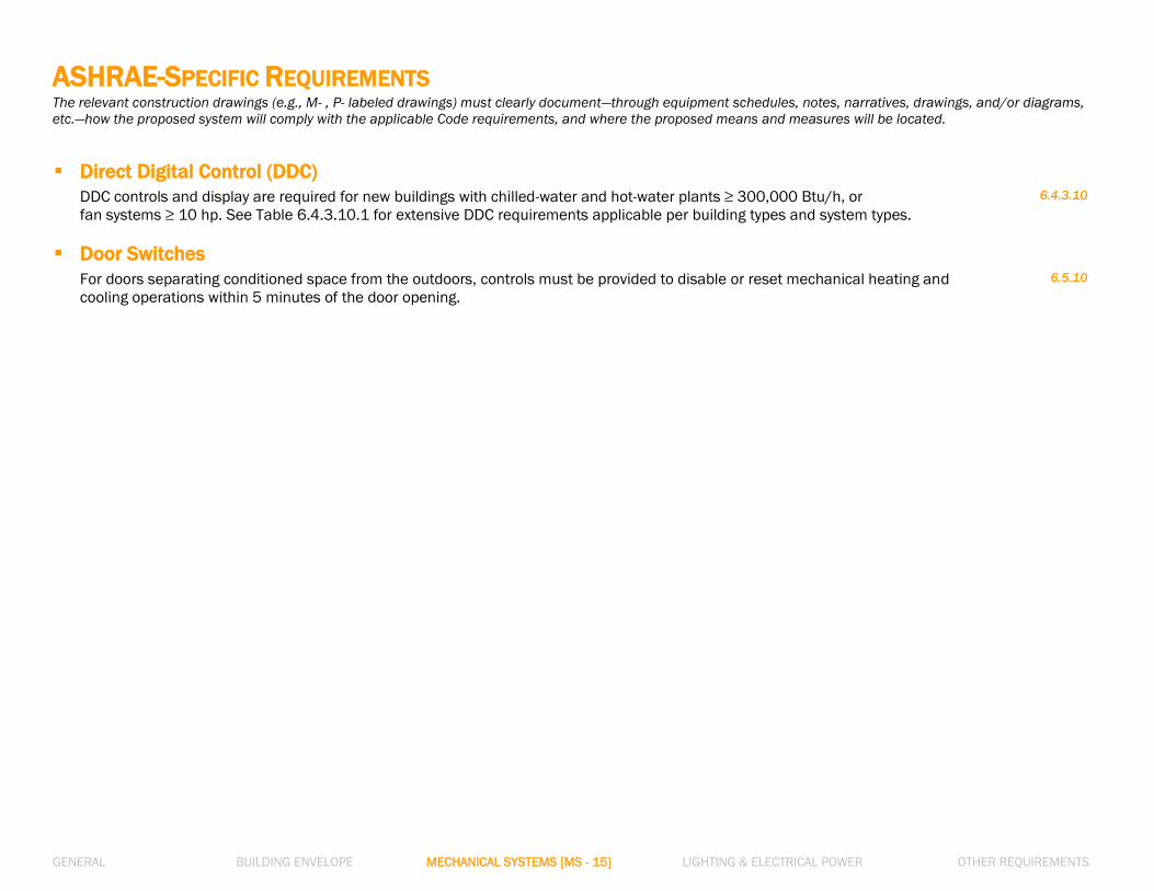
ASHRAE-SPECIFIC REQUIREMENTS The relevant construction drawings (e.g., M- , P- labeled drawings) must clearly document—through equipment schedules, notes, narratives, drawings, and/or diagrams,
etc.—how the proposed system will comply with the applicable Code requirements, and where the proposed means and measures will be located.
Direct Digital Control (DDC)
DDC controls and display are required for new buildings with chilled-water and hot-water plants ≥ 300,000 Btu/h, or
fan systems ≥ 10 hp. See Table 6.4.3.10.1 for extensive DDC requirements applicable per building types and system types.
6.4.3.10
Door Switches
For doors separating conditioned space from the outdoors, controls must be provided to disable or reset mechanical heating and
cooling operations within 5 minutes of the door opening.
6.5.10
GENERAL BUILDING ENVELOPE MECHANICAL SYSTEMS [MS - 16] LIGHTING & ELECTRICAL POWER OTHER REQUIREMENTS
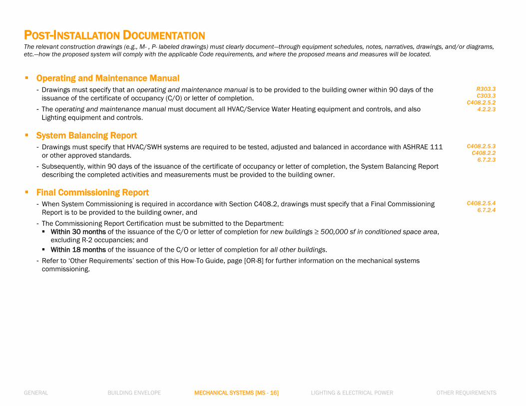
POST-INSTALLATION DOCUMENTATION The relevant construction drawings (e.g., M- , P- labeled drawings) must clearly document—through equipment schedules, notes, narratives, drawings, and/or diagrams,
etc.—how the proposed system will comply with the applicable Code requirements, and where the proposed means and measures will be located.
Operating and Maintenance Manual
- Drawings must specify that an operating and maintenance manual is to be provided to the building owner within 90 days of the
issuance of the certificate of occupancy (C/O) or letter of completion.
- The operating and maintenance manual must document all HVAC/Service Water Heating equipment and controls, and also
Lighting equipment and controls.
R303.3
C303.3
C408.2.5.2
4.2.2.3
System Balancing Report
- Drawings must specify that HVAC/SWH systems are required to be tested, adjusted and balanced in accordance with ASHRAE 111
or other approved standards.
- Subsequently, within 90 days of the issuance of the certificate of occupancy or letter of completion, the System Balancing Report
describing the completed activities and measurements must be provided to the building owner.
C408.2.5.3
C408.2.2
6.7.2.3
Final Commissioning Report
- When System Commissioning is required in accordance with Section C408.2, drawings must specify that a Final Commissioning
Report is to be provided to the building owner, and
- The Commissioning Report Certification must be submitted to the Department:
Within 30 months of the issuance of the C/O or letter of completion for new buildings ≥ 500,000 sf in conditioned space area,
excluding R-2 occupancies; and
Within 18 months of the issuance of the C/O or letter of completion for all other buildings.
- Refer to ‘Other Requirements’ section of this How-To Guide, page [OR-8] for further information on the mechanical systems
commissioning.
C408.2.5.4
6.7.2.4
How-to Guide: Supporting Documentation
In Compliance with
2016 New York City Energy Conservation Code
GENERAL
BUILDING ENVELOPE
MECHANICAL SYSTEMS
LIGHTING & ELECTRICAL POWER
OTHER REQUIREMENTS
NOTE: In this How-To Guide: Supporting Documentation, selected Energy Code provisions have been generalized, summarized, rephrased, and/or highlighted. This guide is intended: 1) To
provide general guidance for the job applications seeking compliance with the 2016 NYCECC; 2) Not to replace or represent the entire 2016 NYCECC and related regulations of the City of
New York and the Department of Buildings; and 3) Not to provide complete compliance solutions for any particular type of job or work. Comprehensive mandates, applicability, exemptions,
exceptions and options will be found in the 2016 NYCECC and related regulations of the City of New York and the Department of Buildings.

GENERAL BUILDING ENVELOPE MECHANICAL SYSTEMS LIGHTING & ELECTRICAL POWER [LE - 1] OTHER REQUIREMENTS
INTERIOR LIGHTING POWER
Maximum Allowed Interior Lighting Power
- Light fixture layout plans and light fixture schedules must demonstrate that the proposed interior lighting power density (watts/sf) is
not greater than the maximum allowed interior lighting power density.
- Light fixture schedules must be complete with fixture identification keys, fixture/lamp type, number of lamps per fixture, fixture
wattages and quantities that match the light fixture layout plans.
- Light fixture schedules must support the lighting energy analysis report: e.g., Lamps/Fixture, # of Fixtures, and Fixture Wattage
listed in Lighting COMcheck report on EN- drawings and must match those values in light fixture schedules on RCP drawings. Refer
to the page [GE-3].
- Fixture efficacy values (lumens/watt), and/or fixtures’ low-voltage information, when pertaining to exemption of certain lighting
power/controls requirements, must also be listed in the light fixture schedules.
C405.4
9.2.2.3
1 RCNY §5000-
01(g)(2)
R404.1
C405.1
9.1.1
Allowance Calculation Method
- The maximum allowed interior Lighting Power Density (LPD) must be determined by either the Building Area Method, or the Space-
by-Space Method. These may not be used in combination.
- The selection of one method between the two, by which the allowed LPD of the job application is determined, must be justified by
the building/space programs and work scope of the job application.
C405.4.2
9.2.2
Building Area Method
Interior Lighting Power Allowance = The floor area of each Building area type x the LPD value for the Building area type from Table
C405.4.2(1), or Table 9.5.1
- For the purposes of this method, an ‘area’ is defined as all contiguous spaces that accommodate or are associated with a single
building area type, as listed in Table C405.4.2(1).
C405.4.2.1
9.2.2.1
LIGHTING FIXTURE SCHEDULE
Fixture ID
SPACE Types MANUFACTURER, MODEL LAMP
TYPE
NUMBER OF
LAMPS/FIXTURE
BALLAST
TYPE
TOTAL NUMBER OF
FIXTURES
FIXTURE
WATTAGE (W)
TOTAL
WATTAGE COMMENTS
L1 Sales Area OOOOOO LIGHTING SYSTEMS -
ECS-LPW-4-WN-232-UNV-12H-RST
TRACK
LIGHT N/A ELECTRONIC 10 Linear Feet N/A 300
30W/LF X 10 LF =
300W
(per ASHRAE 9.1.4 -c.1)
L2 Sales Area OOOO LIGHTING - LED DOWNLIGHT
- #2221W-B1-F-10-LRTD3 LED 1 ELECTRONIC 32 14 448
See Narratives below
for lighting controls.
L3 Dressing/Fitting
Rooms
OO LIGHTING - M40-2-3-OCT-ELD-
UN W. INTEGRAL OCCUP. SENSOR
FLUORE
-SCENT 2 ELECTRONIC 4 64 256
See Narratives below
for lighting controls.
L4 Storage OOO LIGHTING - LED DOWNLIGHT -
#LRTA3-8414-M4-30KS LED 1 ELECTRONIC 58 14 812
See Narratives below
for lighting controls.
L5 Restrooms OOOO LIGHTING - LED DOWNLIGHT
- #999W-D1-A-10-EEE3 LED 1 ELECTRONIC 18 14 252
See Narratives below
for lighting controls.
Figure LE-1. Sample Lighting Fixture Schedule for Retail Space Fit-Out

GENERAL BUILDING ENVELOPE MECHANICAL SYSTEMS LIGHTING & ELECTRICAL POWER [LE - 2] OTHER REQUIREMENTS
INTERIOR LIGHTING POWER
Space-by-Space Method
Interior Lighting Power Allowance = Sum of (the floor area of each Space type x the LPD value for the Space type from Table
C405.4.2(2), or Table 9.6.1)
- The space type in the Table that most closely represents the proposed use of each space must be selected so that all spaces in
the work scope are accounted for in the calculation.
- Trade-offs among spaces are permitted in this method.
C405.4.2.2
9.2.2.2
High-Efficacy Lamps
- For Residential buildings, also for Dwelling units within Commercial buildings, a minimum of 75% of the lamps in newly installed
permanent lighting fixtures must be high-efficacy lamps.
- Light fixture schedules must clearly identify the lamp type (e.g., CFL, T-8, T-5, etc.), efficacy information (in lumens/watt) of all high-
efficacy lamps, and the percentage of the high-efficacy lamps.
R404.1
C405.1
9.1.1
Figure LE-2. High-Efficacy Lamp examples
Source: basc.pnnl.gov
For the definition of “High-Efficacy Lamps,” refer to R202 and C202, or
Section 3 of ASHRAE.

GENERAL BUILDING ENVELOPE MECHANICAL SYSTEMS LIGHTING & ELECTRICAL POWER [LE - 3] OTHER REQUIREMENTS
OCCUPANT SENSOR CONTROLS* Where Required
- Occupant sensor controls are required in spaces including: classrooms, conference rooms, copy rooms, lounges, employee break
rooms, private offices, restrooms, storage rooms, janitor closets, locker rooms, warehouses, open plan offices, and other spaces ≤300
sf.
- Light fixture layout plans, fixture schedules, and the controls narrative must clearly identify the location of occupant-sensor-controlled
light fixtures and the connected sensor/control devices.
C405.2.1
Table 9.6.1
Occupant Sensor Control Function
- Automatic-Off: Drawings must specify that occupant sensor controlled luminaires are automatically turned off within 20 minutes of all
occupants leaving the space.
- Manual-On or Maximum 50% Automatic-On: Lights turned off by occupant sensor controls must be either manually on, or controlled to be
automatically on maximum 50% of the lighting power in the space.
- Manual-On ONLY: Lights turned off by occupant sensor controls must be only manually on – i.e., max. 50% automatic-on is not allowed –
in the following spaces: classrooms, conference/meeting rooms, employee break rooms, and offices < 200 sf. The sensors and controls
in these spaces must not have an override switch that converts from manual-on to automatic-on functionality.
- Full Automatic-On: Only in the following spaces, occupant sensors with full automatic-on are allowed: open plan offices, public corridors,
stairways, restrooms, primary building entrance areas and lobbies, and areas where manual-on operation would endanger the safety or
security of the building occupants.
- Manual Control to Turn Off: Occupant sensor controlled luminaires must also be equipped with manual controls that allow occupants to
turn lights off.
C405.2.1.1
9.4.1.1.b
9.4.1.1.c
Controls in Open Plan Offices
- Lighting in Open Plan offices must be specified to be controlled by occupant sensors.
- The maximum area in the Open Plan offices controlled by one (1) occupant sensing device is 2,500 sf (as compared to the maximum
area of 5,000 sf per device for other occupant-sensor-required areas).
- Full automatic-on controls are allowed in Open Plan offices.
C405.2.1.1
9.4.1.1.h
*For complete controls requirements on ASHRAE 90.1 per space type, refer to Section 9.4.1 and Table 9.6.1.

GENERAL BUILDING ENVELOPE MECHANICAL SYSTEMS LIGHTING & ELECTRICAL POWER [LE - 4] OTHER REQUIREMENTS
TIME-SWITCH & LIGHT-REDUCTION CONTROLS* Where Required
In spaces where occupant sensor controls (previous page) are not provided, both time-switch controls and light-reduction controls
must be provided. The controls’ function and locations must be clearly specified on drawings.
C405.2.2
Time-Switch Controls (Programmed)
Time-switch controls must be designed to:
1) Have a minimum 7-day clock,
2) Allow to program 7-different day types/week,
3) Have an automatic holiday ‘shutoff’ feature,
4) Have program backup capabilities in case of power interruption, and
5) Include a manually-controlled override switch that, when initiated, permits the controlled lighting to remain on for a maximum of 2
hours, and that individually controls a maximum area of 5,000 sf.
C405.2.2.1
Light-Reduction Controls (Manual)
- Spaces with time-switch controls must also be provided with manual light-reduction controls that allow the occupant to reduce the
connected lighting load by minimum 50%.
- Light fixture layout plans must clearly indicate the light-reduction control method, the options of which are as follows:
1) Control of all lamps/luminaires
2) Dual switching of alternate rows of luminaries
3) Switching middle lamp luminaires independently
4) Switching each lamp/luminaire
C405.2.2.2
Figure LE-4.
Light-Reduction
Controls Method by a) Control of all lamps/luminaires b) Dual switching of alternate rows of luminaries c) Switching middle lamp luminaires independently
Source: energycodes.gov
*For complete controls requirements on ASHRAE 90.1 per space type, refer to Section 9.4.1 and Table 9.6.1.

GENERAL BUILDING ENVELOPE MECHANICAL SYSTEMS LIGHTING & ELECTRICAL POWER [LE - 5] OTHER REQUIREMENTS
For areas/rooms where exemptions of certain lighting controls are
sought, the lighting plans and narratives must provide clear
information to satisfy the exemption requirements.
TIME-SWITCH & LIGHT-REDUCTION CONTROLS* Where Time-Switch Controls are Exempt
If the spaces listed below are provided with manual lighting-reduction controls, time-switch controls are not required:
1) Sleeping units
2) Spaces where patient care is directly provided
3) Spaces where an automatic shutoff would endanger occupant safety or security
4) Lighting intended for continuous operation
5) Shop and laboratory classrooms
C405.2.2
Where Light-Reduction Controls are Exempt
Light reduction controls are not required in daylight zones with daylight responsive controls complying with Section C405.2.3.
C405.2.2.2
*For complete controls requirements on ASHRAE 90.1 per space type, refer to Section 9.4.1 and Table 9.6.1.
Figure LE-5.b. Daylight zone with automatic controls Exempt from Light-Reduction Controls
Source: energycodes.gov/training
Figure LE-5.a. Patient care area Exempt from Time-Switch Controls
Source: energy.gov/eere

GENERAL BUILDING ENVELOPE MECHANICAL SYSTEMS LIGHTING & ELECTRICAL POWER [LE - 6] OTHER REQUIREMENTS
DAYLIGHT-RESPONSIVE CONTROLS* Control Function
- For spaces having electric lights > 150 watts within daylight zones, independent controls for the lights within daylight zones must
be specified.
- For this purpose, light fixture layout plans must clearly delineate the boundary of each daylight zone, and indicate separate
circuiting and switch control for each zone boundary.
- Daylight-responsive controls must be designed to be capable of a complete shutoff of lights within each daylight zone, and must be
installed such that authorized professionals can readily access the controls for calibration.
C405.2.3
9.4.1.1.e & f
9.7.2.3
Sidelight Daylight Zone
- The sidelight daylight zone must be identified on drawings in the floor area adjacent to vertical fenestration.
- When the fenestration is located in a wall, the daylight zone extends:
(a) Laterally to the nearest full-height wall, or up to 1-times the height from the floor to the top of the fenestration, and
(b) Longitudinally from the edge of the fenestration to the nearest full-height wall, or up to 2 ft, whichever is less.
- For the criteria of daylight zone following ASHRAE, refer to the definition of ‘daylight area’ in ASHRAE Section 3.2.
C405.2.3.2
3.2
*For complete controls requirements on ASHRAE 90.1 per space type, refer to Section 9.4.1 and Table 9.6.1.
For Daylight Zone under
Fenestration located in a Rooftop
Monitor following ECC, refer to
Figure C405.2.3.2(2) and
C405.2.3.2(3).
For Daylight Zone computations
following ASHRAE, refer to Figure
3.2-1 through Figure 3.2-4.
Figure LE-6.
Daylight Zone Adjacent to Fenestration in a Wall
(a) Section view
(b) Plan view of daylight zone adjacent to fenestration in a wall

GENERAL BUILDING ENVELOPE MECHANICAL SYSTEMS LIGHTING & ELECTRICAL POWER [LE - 7] OTHER REQUIREMENTS
DAYLIGHT-RESPONSIVE CONTROLS* Toplight Daylight Zone
- The toplight daylight zone must be identified on drawings in the floor area underneath a roof fenestration assembly.
- The daylight zone under a roof skylight extends laterally and longitudinally beyond the edge of the roof skylight: (a) To the nearest obstruction that is taller than 0.7-times the ceiling height, or
(b) Up to 0.7-times the ceiling height, whichever is less.
- For the criteria of daylight zone following ASHRAE, refer to the definition of ‘daylight area’ in ASHRAE Section 3.2.
C405.2.3.3
3.2
*For complete controls requirements on ASHRAE 90.1 per space type, refer to Section 9.4.1 and Table 9.6.1.
Figure LE-7.
Daylight Zone Under a Roof Fenestration Assembly
For Daylight Zone computations
following ASHRAE, refer to Figure
3.2-1 through Figure 3.2-4.
(a) Section view
(b) Plan view of daylight zone under a roof fenestration assembly

GENERAL BUILDING ENVELOPE MECHANICAL SYSTEMS LIGHTING & ELECTRICAL POWER [LE - 8] OTHER REQUIREMENTS
EXTERIOR LIGHTING POWER Maximum Allowed Exterior Lighting Power
- Light fixture layout plans and light fixture schedules must demonstrate:
Proposed exterior lighting power density (watts/sf) ≤ Maximum allowed exterior lighting power density
- Light fixture schedules must be complete with fixture identification keys, fixture/lamp type, number of lamps per fixture, fixture
wattages and quantities that match the light fixture layout plans.
C405.5.1
9.4.2
Calculation of Maximum Allowance
- The maximum allowed building exterior lighting power must be computed based on Table C405.5.2(2) for the applicable Exterior
Lighting Zone per 1 RCNY §5000-01(g)(3)(ii).
Maximum Allowed Exterior
Lighting Power
= Base Site Allowance
(per Lighting Zone)
+ Individual Allowance per Area Type
(Tradable/Non-Tradable Surfaces)
- Trade-offs are allowed only among exterior lighting applications in the Tradable Surfaces of Table
C405.5.2(2).
C405.5.1
1 RCNY §5000-01
(g)(3)(ii)
9.4.2
Lighting Zone 1: Park land.
Lighting Zone 2: All R districts, R districts with C overlays and MX districts.
Lighting Zone 3: M districts, except MX; C districts, except C5, C6 and C overlays on R districts.
Lighting Zone 4: C5 and C6 districts
Exterior Lighting Zone
Exterior Lighting Controls
- Drawings must specify that the building exterior lighting systems are provided with controls that automatically turn off the lighting as
a function of available daylight.
- For systems illuminating the building façade or landscape, the lighting must have controls that automatically shut off the lighting as
a function of dawn/dusk and a set opening and closing time.
- For all other building exterior lighting, the lighting must have controls that automatically reduce the connected lighting power by
minimum 30% during the nighttime.
C405.2.5
9.4.1.4
Figure LE-8. Exterior Lighting Zone per 1 RCNY §5000-01 (g)(3)(ii) Source: energycodes.gov

GENERAL BUILDING ENVELOPE MECHANICAL SYSTEMS LIGHTING & ELECTRICAL POWER [LE - 9] OTHER REQUIREMENTS
OTHER LIGHTING REQUIREMENTS Narrative on Lighting System and Controls
On drawings where light fixture layout plans and schedules are documented, a narrative must be provided to describe the function
and operation of mandatory lighting and power controls.
1 RCNY §5000-01
(g)(3)
Lighting System Functional Testing
Drawings must specify the requirements that:
- The approved agency must certify that the installed lighting control systems including occupant sensor controls, time-switch
controls, and daylight-responsive controls have been tested and perform as intended.
- Documents certifying the installed lighting controls meet documented performance criteria of Section C405 must be provided to
the building owner within 90 days of the receipt of the certificate of occupancy.
C408.3
9.4.4
Hotel Guestrooms
For hotel and motel guestrooms (sleeping units or guest suites), drawings must specify a master control device that is capable of
automatically switching off all installed luminaires and switched receptacles within 20 minutes of all occupants leaving the
guestroom.
C405.2.4
9.4.1.3
Display and Accent Lighting
Display lights, accent lights, and lighting in display cases must be controlled by a dedicated control that is independent of the
controls for other lighting within the room or space. Controls’ locations must be clearly noted on the light fixture layout plans.
C405.2.4
9.4.1.3
Parking Garage
Parking garage lighting must be designed so that:
1) Scheduled automatic shutoff is incorporated;
2) Luminaire lighting power is automatically reduced by minimum 30% within 20 minutes of no activity detected in each lighting
zone of maximum 3,600 sf;
3) Luminaires for covered garage entrances and exits are separately controlled so the lighting power is automatically reduced by
minimum 50% from sunset to sunrise; and
4) Luminaires within 20 ft of walls with window openings have a daylight-responsive control.
9.4.1.2
Exit Signs
Light fixture schedules must indicate that the wattage of exit signs (internally illuminated type signs) is maximum 5 watts per side.
C405.3
9.4.3

GENERAL BUILDING ENVELOPE MECHANICAL SYSTEMS LIGHTING & ELECTRICAL POWER [LE - 10] OTHER REQUIREMENTS
ELECTRICAL POWER REQUIREMENTS Voltage Drop
The conductors for feeders and branch circuits combined must be sized for a maximum of 5% voltage drop total, unless the feeder
conductors and branch circuits are dedicated to emergency services.
8.4.1
Automatic Receptacle Control
Drawings must specify that: - Minimum 50% of receptacles in spaces including private offices, conference rooms, and classrooms, etc., and
- Minimum 25% of branch circuit feeders in modular furniture are automatically controlled:
1) On a scheduled basis, or
2) By occupant sensors, or
3) By an automated signal from another control or alarm system.
8.4.2
Separate Metering for Dwelling Units and Large Tenant Spaces
Drawings must indicate that:
- Each dwelling unit in a Group R-2 building must be provided with a separate electrical meter.
- Each covered tenant space in a new building must be provided with a separate meter or sub-meter to measure the electrical
consumption of each space.
- Locations of electrical meters must be shown on plan drawings.
R404.2
C405.6.1
8.4.5
Electrical Energy Monitoring for Whole Building and Large Tenant Spaces
- For new buildings ≥ 25,000 sf,
- For large tenant spaces ≥ 10,000 sf within new buildings, and
- For new residential building common areas ≥ 10,000 sf
measurement devices must be installed to monitor the electrical energy use for each of the following separately:
1) Total electrical energy
2) HVAC systems
3) Interior lighting
4) Exterior lighting
5) Receptacle circuits.
8.4.3
Definition of “Covered Tenant Space”:
(a) A tenant space > 5,000 GSF on one or more floors of a
covered building let or sublet to the same person, or
(b) A floor > 5,000 GSF of a covered building consisting of
tenant spaces let or sublet to two or more different persons.
For the definition of Covered Building, refer to Section 28-
311.2 of the Administrative Code of the City of New York.

GENERAL BUILDING ENVELOPE MECHANICAL SYSTEMS LIGHTING & ELECTRICAL POWER [LE - 11] OTHER REQUIREMENTS
ELECTRICAL POWER REQUIREMENTS Elevator Cabs
Drawings must specify that:
- Lighting efficacy: For each elevator cab’s interior lighting, total lumens divided by total watts must be ≥ 35 lumens/watt.
- Ventilation fan power: Ventilation fans in elevator cabs without their own air-conditioning system must not consume power > 0.33
watts/cfm.
- Controls to de-energize: When stopped and unoccupied with doors closed for over 15 minutes, cab interior lighting and ventilation
systems must be automatically controlled to be de-energized.
C405.9.1
10.4.3
Escalators and Moving Walks
- Automatic speed reduction: Drawings must specify that escalators and moving walks have controls to automatically reduce speed
when not conveying passengers.
- Regenerative Drive: An escalator designed either for one-way down operation only or for reversible operation must have a variable
frequency regenerative drive that supplies electrical energy to the building electrical system when the escalator is loaded with
passengers whose combined weight > 750 pounds.
C405.9.2
10.4.4
Figure LE-11. Escalator Variable Frequency Regenerative Drive

How-to Guide:
Supporting Documentation
In Compliance with
2016 New York City Energy Conservation Code
GENERAL
BUILDING ENVELOPE
MECHANICAL SYSTEMS
LIGHTING & ELECTRICAL POWER
OTHER REQUIREMENTS
NOTE: In this How-To Guide: Supporting Documentation, selected Energy Code provisions have been generalized, summarized, rephrased, and/or highlighted. This guide is intended: 1) To
provide general guidance for the job applications seeking compliance with the 2016 NYCECC; 2) Not to replace or represent the entire 2016 NYCECC and related regulations of the City of
New York and the Department of Buildings; and 3) Not to provide complete compliance solutions for any particular type of job or work. Comprehensive mandates, applicability, exemptions,
exceptions and options will be found in the 2016 NYCECC and related regulations of the City of New York and the Department of Buildings.

GENERAL BUILDING ENVELOPE MECHANICAL SYSTEMS LIGHTING & ELECTRICAL POWER OTHER REQUIREMENTS [OR- 1]
MANDATORY ADDITIONAL EFFICIENCY PACKAGE (NYCECC-only * Requirements)
Six Options (must choose at least one)
- New Commercial buildings that choose NYCECC* as Code compliance path must demonstrate compliance with at least one of
the following as an additionally required energy efficiency system:
C406.1
Option 1. More Efficient HVAC Performance
C406.2
Option 2. Reduced Lighting Power Density
C406.3
Option 3. Enhanced Digital Lighting Controls
C406.4
Option 4. On-Site Supply of Renewable Energy
C406.5
Option 5. Provision of Dedicated Outdoor Air System (DOAS)
C406.6
Option 6. High Efficiency Service Water Heating
C406.7
- New Tenant spaces that choose NYCECC* as Code compliance path must demonstrate compliance with one of the following:
Option 1, Option 2, Option 3, Option 5, or Option 6. Alternatively, New Tenant spaces may demonstrate compliance with Option 4
where the entire building is in compliance with Option 4.
C406.1.1
Job applications that chose ‘NYCECC’ as the ‘Code Compliance Path’—on PW1-Section 10, ‘NYCECC’ has been marked—must comply with
the requirement of Additional Efficiency Package. In other words, job applications following ASHRAE are not subject to this requirement
(Section C406).
*

GENERAL BUILDING ENVELOPE MECHANICAL SYSTEMS LIGHTING & ELECTRICAL POWER OTHER REQUIREMENTS [OR- 2]
MANDATORY ADDITIONAL EFFICIENCY PACKAGE Option 1. More Efficient HVAC Performance
HVAC equipment schedules on construction drawings must clearly indicate that: C406.2
All proposed Energy-Code-regulated equipment exceed the minimum efficiency requirements listed in Tables C403.2.3(1) through C403.2.3(7), C403.2.3(11), and C403.2.3(12) by 10%, in addition to meeting the mandatory requirements of Section C403.
Equipment not listed in Tables C403.2.3(1) through C403.2.3(7), C403.2.3(11), and C403.2.3(12) are limited to maximum 10% of the total building system capacity.
Option 2. Reduced Lighting Power Density Construction drawings must prove that the total interior lighting power (watts) of the building are determined by using:
- 90% of the interior lighting power values specified in Table C405.4.2(1) times the floor area for the building types, or
- 90% of the interior lighting power allowance calculated by the Space-by-Space Method in Section C405.4.2.2.
C406.3
Figure OR-2. Examples of High-Efficacy Lamps
Source: energycodes.gov

GENERAL BUILDING ENVELOPE MECHANICAL SYSTEMS LIGHTING & ELECTRICAL POWER OTHER REQUIREMENTS [OR- 3]
MANDATORY ADDITIONAL EFFICIENCY PACKAGE
Option 3. Enhanced Digital Lighting Controls Construction drawings must specify that all of the interior lighting systems in the building have all of the following enhanced lighting
controls and will be located, scheduled and operated in accordance with Section C405.2.2:
1) Luminaires capable of continuous dimming,
2) Luminaires capable of being addressed individually, or in a group of maximum 4 luminaires when individual addressability is
technically unachievable,
3) Maximum 8 luminaires controlled together in a Daylight zone,
4) Fixtures controlled through a digital control system that include the following functions:
- Control reconfiguration based on digital addressability
- Load shedding
- Individual user control of overhead general illumination in open offices
- Occupancy sensors capable of being reconfigured through the digital control system,
5) Construction documents specifying requirement for submittal of a Sequence of Operations, including specifications outlining
each of the functions in Item 4) above, and
6) Functional testing of lighting controls complying with Section C408. Lighting/Power plans, light fixture schedules, specification notes, controls narrative, etc.—all combined together must clearly identify
the enhanced lighting controls.
C406.4
Option 4. On-Site Supply of Renewable Energy
Construction drawings must specify the proposed on-site renewable energy systems with sufficient system details to prove that the
total minimum ratings of the systems must comply with one of the following:
1) Provide minimum 0.5 watts/sf of conditioned floor area, or
2) Provide minimum 3% of energy used within the building for building mechanical and service water heating equipment and
lighting regulated in Chapter C4.
C406.5
Figure OR-3. Solar Photovoltaic: Sample On-Site Renewable Energy System
Source: energy.gov/revolution-now
energycodes.gov/training
Source: (www.Energy.gov)

GENERAL BUILDING ENVELOPE MECHANICAL SYSTEMS LIGHTING & ELECTRICAL POWER OTHER REQUIREMENTS [OR- 4]
MANDATORY ADDITIONAL EFFICIENCY PACKAGE
Option 5. Provision of a Dedicated Outdoor Air System (DOAS) for Certain HVAC Equipment This option is applicable to building HVAC equipment system complying with Section C403.4 Hydronic and multiple-zone HVAC systems
controls and equipment.
C406.6
For job applications electing this option, construction drawings must indicate that the building HVAC systems are equipped with an
independent ventilation system designed to provide 100% outdoor air to each individual occupied space.
Construction drawings also must specify that:
- The ventilation system must have total energy recovery capacity.
- The HVAC system must include supply-air temperature controls that automatically reset the supply-air temperature in response to
representative building loads, or to outdoor air temperatures.
- The controls must reset the supply-air temperature to a minimum 25% of the difference between the design supply-air temperature and the
design room-air temperature.
Option 6. High Efficiency Service Water Heating This High Efficiency Service Water Heating (SWH) system option is applicable to the following Occupancy Group types only:
- Group R-1: Boarding houses, hotel or motels
- Group R-2: Buildings with residential occupancies
- Group A-2: Restaurants and banquet halls or buildings containing food preparation areas
- Group A-3: Health clubs and spas
- Group I-2: Hospitals, psychiatric hospitals and nursing homes
- Group F: Laundries
For a mixed-use building comprised of partial building areas of the above-listed occupancy, the SWH system serving only the building
areas of such occupancies will be eligible for this option.
C406.7
The SWH equipment schedule must demonstrate reduced energy use in the SWH system by incorporating the following:
1) Waste heat recovery from service hot water, heat-recovery chillers, building equipment, process equipment, or a
combined heat and power system,
and/or
2) Solar water-heating systems,
and
The incorporated systems as the above are sized to provide:
- Minimum 60% of hot water requirements, or
- 100% of hot water requirements if compliance with Section C403.4.5 is required.

GENERAL BUILDING ENVELOPE MECHANICAL SYSTEMS LIGHTING & ELECTRICAL POWER OTHER REQUIREMENTS [OR- 5]
PERMANENT CERTIFICATE – RESIDENTIAL BUILDINGS REQUIREMENT For Residential building job applications, the builder or registered design professional must complete or update the Permanent Energy Efficiency
Certificate, and have it installed prior to final inspections of the application.
Permanent Certificate Must List the Following at a Minimum
- Predominant R-values of insulation installed in or on ceiling/roof, walls, foundation, and ducts outside the envelope
- U-factors/SHGC values of fenestration
- Air leakage testing results
- Types and efficiencies of HVAC and Service water heating equipment
- Location of the Solar-Ready zone and pathways to the electrical service panel or service hot water system
1 RCNY §5000-01(g)(5)
R401.3
RB103.8
Location of the Permanent Certificate
- Drawings must specify that the Certificate will be posted on a wall in the space where the furnace is located, a utility room
or an approved location inside the building prior to final inspections of the application.
- When specifying to post the Certificate near or on the electrical distribution panel, drawings must also instruct that the
Certificate must be readily visible (at eye level and in plain sight), and yet must not obstruct the visibility of the other Code-
required labels (e.g., circuit directory label, service disconnect label, etc.).
Additions & Alterations Job Applications
For Additions and Alterations applications affecting information on the existing Permanent Certificate, drawings should
specify that the existing Certificate must be updated and re-installed.
Figure OR-5.a. Sample Permanent Energy Efficiency Certificate (partial view)
[Click here for the full certificate view]
Figure OR-5.b. Sample Plan Drawing indicating Certificate Requirement
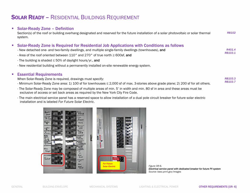
GENERAL BUILDING ENVELOPE MECHANICAL SYSTEMS LIGHTING & ELECTRICAL POWER OTHER REQUIREMENTS [OR- 6]
SOLAR READY – RESIDENTIAL BUILDINGS REQUIREMENT Solar-Ready Zone – Definition
Section(s) of the roof or building overhang designated and reserved for the future installation of a solar photovoltaic or solar thermal
system.
RB102
Solar-Ready Zone is Required for Residential Job Applications with Conditions as follows - New detached one- and two-family dwellings, and multiple single-family dwellings (townhouses), and
- Area of the roof oriented between 110° and 270° of true north ≥ 600sf, and
- The building is shaded ≤ 50% of daylight hours/yr., and
- New residential building without a permanently installed on-site renewable energy system.
R401.4
RB103.1
Essential Requirements
When Solar-Ready Zone is required, drawings must specify:
- Minimum Solar-Ready Zone area: 1) 100 sf for townhouses ≤ 2,000 sf of max. 3-stories above grade plane; 2) 200 sf for all others.
- The Solar-Ready Zone may be composed of multiple areas of min. 5’ in width and min. 80 sf in area and these areas must be
exclusive of access or set back areas as required by the New York City Fire Code.
- The main electrical service panel has a reserved space to allow installation of a dual pole circuit breaker for future solar electric
installation and is labeled For Future Solar Electric.
RB103.3
RB103.7
Figure OR-6.
Electrical service panel with dedicated breaker for future PV system
Source: basc.pnnl.gov/images
For Future
Solar Electric

GENERAL BUILDING ENVELOPE MECHANICAL SYSTEMS LIGHTING & ELECTRICAL POWER OTHER REQUIREMENTS [OR- 7]
ENERGY RATING INDEX (ERI) – COMPLIANCE ALTERNATIVE FOR RESIDENTIAL BUILDINGS ERI is a score-based rating system which alternatively determines Energy Code compliance of a new residential building based on its energy performance.
It allows applicants to approach the Energy Code with the same flexibility of the Simulated Performance Alternative (Section R405), yet it uses energy
modeling and in-field inspection to confirm that results are achieved.
ERI ‘Reference Design’ vs. ‘Rated Design’
The ERI Reference Design, representing ERI score of 100, means the building design meets the minimum requirements of the 2006
IECC. For Rated Design of a newly proposed residential building to demonstrate compliance with the 2016 NYCECC, the ERI
analysis on the building must result in the ERI score of 54 or less (for Climate zone 4). A residential building that achieves the rated
ERI score of 54 is 46% more energy efficient than the Reference Design building, which meets the 2006 IECC (ERI score of 100).
R406.3.1
R406.4
For Compliance Through ERI Approach, Drawings Must Indicate:
1) Mandatory provisions for Residential buildings (Section R401 thru Section R404) and Section R403.5.3 are met.
2) The building thermal envelope meets the 2011 NYCECC prescriptive requirements (Table 402.1.1 or Section 402.1.3).
3) Verification of compliance is required to be completed by an approved third party.
4) Documentation is required regarding: a) Compliance software tools, b) Compliance report, and c) Other additional documentation
that may be required to submit to the Department.
5) Calculation software tools, where used, meet the requirements on: a) Minimum capabilities, b) Specific approval, and c) Input
values.
R406.2
R406.5
R406.6
R406.7
For job applications opting for this compliance path, on PW1-Section 10,
‘Energy Modeling (EN1)’ should be marked as Energy Analysis method.
Figure OR-7. Sample Energy Rating Index Label

GENERAL BUILDING ENVELOPE MECHANICAL SYSTEMS LIGHTING & ELECTRICAL POWER OTHER REQUIREMENTS [OR- 8]
SYSTEM COMMISSIONING Specify Total Proposed Heating and Cooling Capacity
- For ALL Commercial job applications – New buildings or Alterations, Multifamily or Commercial occupancy,
Total Heating Capacity (in Btu/h) proposed by newly installed mechanical equipment, and
Total Cooling Capacity (in Btu/h) proposed by newly installed mechanical equipment
Must be clearly calculated and documented on an EN- labeled sheet.
- In the ‘Total Heating Capacity’ calculations, the ‘Service Water Heating’ equipment capacity must also be included.
Specify Whether System Commissioning is Required
- For ALL job applications – New buildings or Alterations, Residential or Commercial Buildings – drawings (on an EN-
labeled sheet) must clearly state whether or not System Commissioning is required.
- System Commissioning is not required for:
Mechanical Systems of Total proposed Heating capacity < 600,000 Btu/h; and
Total proposed Cooling capacity < 480,000 Btu/h, and
Renewable Energy Systems of Total generating capacity < 25 kW
1 RCNY §5000-01(g)(4)(iii)
C408.2
6.7.2.4
Areas Where Commissioning is Required
- For job applications with systems for which Commissioning is required, drawings should clearly identify specifications of each
Commissioning-required system with detailed information on the equipment/fixture schedules and complete narratives including
controls notes.
- Commissioning-required systems, at a minimum, include the following:
Mechanical Systems
1) Heating, cooling, air handling and distribution, ventilation and exhaust systems;
2) Energy recovery systems;
3) Manual or automatic controls;
4) Plumbing systems;
5) Service water heating systems;
6) Refrigeration systems;
7) Renewable energy and energy storage systems; and
8) Other systems/equipment/components supporting HVAC and affecting energy use.
Lighting Control Systems
1) Occupant sensor controls;
2) Time-switch controls; and
3) Daylight responsive controls.
C408.2
C408.3.1
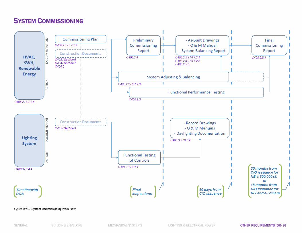
GENERAL BUILDING ENVELOPE MECHANICAL SYSTEMS LIGHTING & ELECTRICAL POWER OTHER REQUIREMENTS [OR- 9]
SYSTEM COMMISSIONING
Figure OR-9. System Commissioning Work Flow

GENERAL BUILDING ENVELOPE MECHANICAL SYSTEMS LIGHTING & ELECTRICAL POWER OTHER REQUIREMENTS [OR- 10]
CHANGES TO EXISTING BUILDINGS
Compliance - Job applications of additions, alterations, repairs or relocation of existing buildings/structures, or changes of occupancy to existing
buildings must demonstrate compliance with the NYCECC and other governing NYC Codes that are effective as of the job
application filing date.
- Job applications following ECC must comply with:
1) Section R502/Section C502 for Additions
2) Section R503/Section C503 for Alterations
3) Section R504/Section C504 for Repairs
4) Section R505/Section C505 for Changes of Occupancy or Use
- Job applications following ASHRAE must comply with:
1) Provisions of Sections 5, 6, 7, 8, 9 and 10 or Section 11 or Appendix G for Additions
2) Provisions of Sections 5, 6, 7, 8, 9 and 10 or Section 11 or Appendix G for Alterations
3) Provisions of Sections 5, 6, 7, 8, 9 and 10 for Repairs and Changes of Occupancy or Use
R501.4
C501.4
4.2.1.2
4.2.1.3
Clear Scope of Work
- Construction drawings must clearly define the proposed scope of work in the existing buildings by:
1) Written descriptions of all proposed changes to the existing buildings, and
2) Graphical delineations of the proposed work on drawings to separate the areas affected by ‘additions, alterations, repairs,
relocations, or changes of C/O’ from the areas of ‘existing-to-remain.’
1 RCNY §5000-01(g)
Alterations vs. Additions on ‘Historic Building’
- Repair, restoration and alteration work of, and change of occupancy to ‘Historic Building’ are exempt from the ECC compliance
requirements. This base for exemption must be stated in the Professional Statement.
- The ECC exemption for ‘Historic Building’ is limited to the National or New York State Historic Buildings, i.e., buildings that are
registered or eligible for registration as a National or New York State Historic Building, or designated as a contributing building in a
National or State Historic District.; New York City-designated historic buildings are NOT exempt. For the complete definition of ‘Historic
Building,’ refer to Section R202 or Section C202.
- Job applications declaring exemptions of ECC compliance for the reason of ‘Historic Buildings’ must present evidence of such eligibility
on drawings. An EN- labeled drawing with Professional Statement claiming exemption from ECC compliance must also include:
1) Documentation obtained from the New York State Historic Preservation Office’s online tool called CRIS* clearly indicating the
subject building is listed as, or is eligible for listing as an historic building, or
2) A letter from the New York State Historic Preservation Office, or the United States Department of the Interior verifying the subject
building is listed as, or is eligible for listing as an historic building.
- Additions to ‘Historic Building’ are NOT exempt, and thus the ‘Added’ portion to the Historic Building must demonstrate compliance
with the ECC according to provisions under Section R502 or Section C502.
R501.6
C501.6
CRIS (Cultural Resource Information System): cris.parks.ny.gov
*

GENERAL BUILDING ENVELOPE MECHANICAL SYSTEMS LIGHTING & ELECTRICAL POWER OTHER REQUIREMENTS [OR- 11]
CHANGES TO EXISTING BUILDINGS A. Additions
- In general, altered portions that resulted from the proposed ‘addition’ in the existing building or building system are subject to the
ECC requirements for new buildings.
- Specifically, Residential buildings must demonstrate compliance by: 1) Prescriptive compliance option per Section R502.1.1, or 2)
Simulated Performance Alternative (Existing plus addition compliance) option per Section R502.1.2.
- Specifically, Commercial buildings must demonstrate compliance by: 1) Prescriptive compliance option per Section C502.2, or 2)
satisfying Appendix CA (ASHRAE 90.1) applicable sections.
- Compliance of the ‘addition’ must be demonstrated by showing that:
1) The ‘addition’ portion alone complies with the ECC prescriptively; or
2) The existing building and the ‘addition’ combined, as a single building, comply with the ECC through the performance path; or
3) For Residential buildings, the existing building with the ‘addition’ uses no more energy than the existing building prior to the
‘addition.’
R502
C502
B. Alterations
- In general, altered portions that resulted from the proposed ‘alteration’ in the existing building or building system are subject to
the ECC requirements for new buildings.
- The following alterations, provided that the energy use of the building after the ‘alteration’ is not increased, need not comply with
the requirements for new buildings:
1) Storm windows installed over existing fenestration
2) Surface-applied window film installed on existing single-pane fenestration assemblies reducing solar heat gain
3) Existing ceiling, wall or floor cavities exposed during construction, provided that cavities are completely filled with insulation
4) Construction where the existing roof, wall or floor cavity is not exposed
5) Roof recover
6) Re-roofing of roofs without insulation in the cavity, providing new insulation either above or below the exposed sheathing
(Residential buildings only)
7) Alterations that replace less than 20% of the luminaires in a space (commercial buildings only)
8) Air barriers are not required for roof recover and roof replacement unless the entire existing building envelope is in the work
scope of alterations, renovations or repairs (commercial buildings only)
- Compliance requirements for ‘alterations’ in Residential buildings
1) Replacement fenestration: Section R503.1.1.1
2) Heating and cooling systems: Section R503.1.2
3) Service hot water systems: Section R503.1.3
4) Lighting: Section R503.1.4
R503
C503
GENERAL BUILDING ENVELOPE MECHANICAL SYSTEMS LIGHTING & ELECTRICAL POWER OTHER REQUIREMENTS [OR- 12]
CHANGES TO EXISTING BUILDINGS B. Alterations (continued from the previous page)
- Compliance requirements for ‘alterations’ in Commercial buildings
1) Building Envelope: Section C503.3
2) Heating and cooling systems: Section C503.4
3) Service hot water systems: Section C503.5
4) Lighting systems: Section C503.6
- Alterations in Commercial buildings complying with Appendix CA (ASHRAE 90.1) need not comply with Section C503.
- Any areas converted from non-conditioned or low-energy space to conditioned space must demonstrate compliance according to
Section R503 or Section C503.
R503
C503
C. Repairs
- While building maintenance and repairs must be conducted in compliance with relevant New York City Codes, work on
damaged/non-damaged building components justified by the required repair/maintenance in the existing building are considered
as ‘repairs’ work, and are not subject to the requirements for Alterations in Section R503/Section C503.
- The following are considered ‘repairs’:
1) Glass-only replacements in fenestration
2) Roof repairs
3) Replacement of the bulb and/or ballast within the existing luminaires in a space, without increasing the installed interior
lighting power
4) Replacement of existing doors that separate conditioned space from the exterior, without removing the existing vestibule
(Commercial buildings only)
5) Air barriers are not required for roof repair unless the entire existing building envelope is in the work scope of alterations,
renovations or repairs (Commercial buildings only)
- Repairs in Commercial buildings complying with Appendix CA (ASHRAE 90.1) need not comply with Section C504.
R504
C504
D. Change of Occupancy or Use
- Buildings/spaces seeking a Change in Occupancy or Use that would result in an increase in energy use – in demand for either
fossil fuel or electrical energy – must meet the ECC requirements applicable to the new occupancy/use.
- Residential buildings/spaces may demonstrate compliance with this section (Section R505) by the Simulated Performance
Alternative method (Section R405) proving that the annual energy cost of the proposed design is no more than 110% of the
annual energy cost of the standard reference design.
- Spaces in Commercial buildings undergoing a change in use must comply with interior lighting power requirements (Section
C405.4) for the new use.
R505
C505