Embed Size (px)
Citation preview
JRF Engineering © 2008
1
How to Design an Air Cooled Cigar Humidor (Thermal Conductivity of Wood and Glass)
By Jim Forgione
Release: Final, Rev 4: 8/8/08
Email: [email protected]
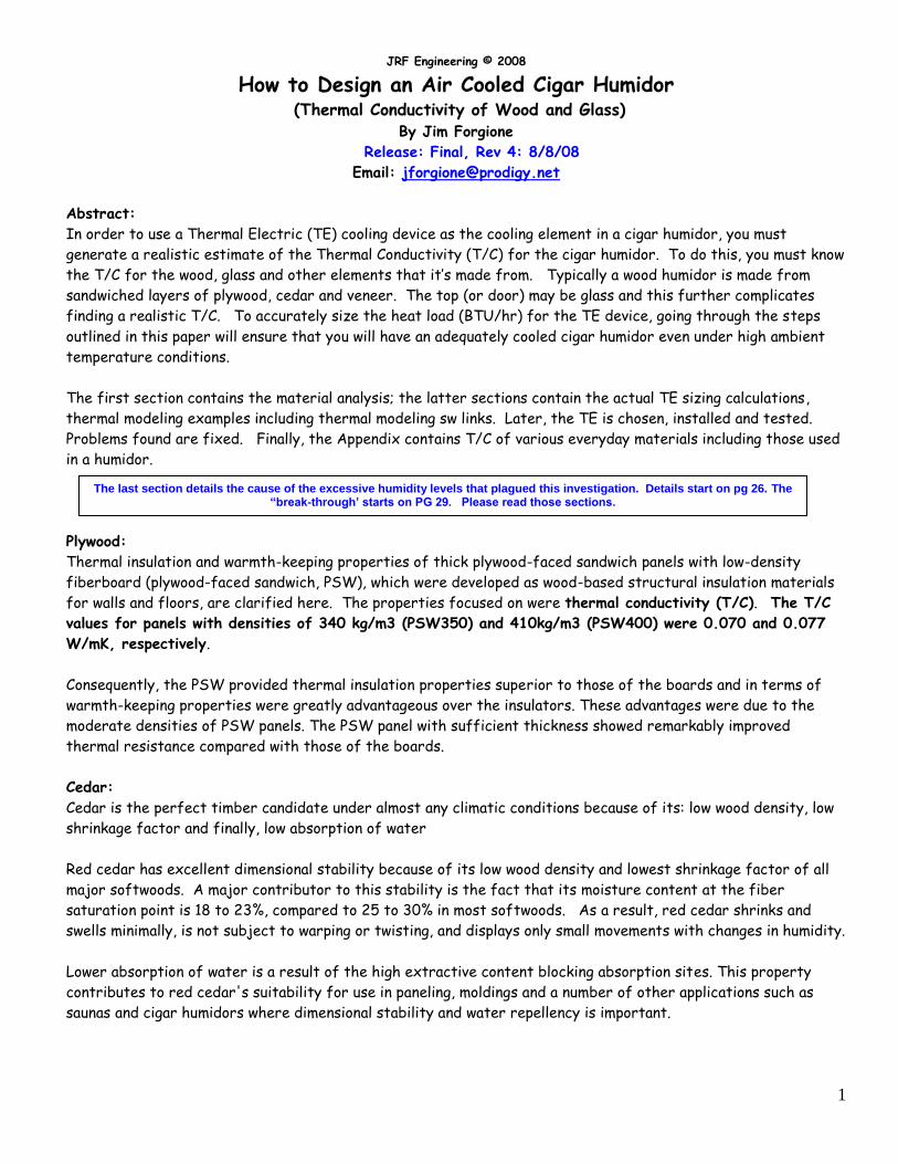
Abstract:
In order to use a Thermal Electric (TE) cooling device as the cooling element in a cigar humidor, you must
generate a realistic estimate of the Thermal Conductivity (T/C) for the cigar humidor. To do this, you must know
the T/C for the wood, glass and other elements that it’s made from. Typically a wood humidor is made from
sandwiched layers of plywood, cedar and veneer. The top (or door) may be glass and this further complicates
finding a realistic T/C. To accurately size the heat load (BTU/hr) for the TE device, going through the steps
outlined in this paper will ensure that you will have an adequately cooled cigar humidor even under high ambient
temperature conditions.
The first section contains the material analysis; the latter sections contain the actual TE sizing calculations,
thermal modeling examples including thermal modeling sw links. Later, the TE is chosen, installed and tested.
Problems found are fixed. Finally, the Appendix contains T/C of various everyday materials including those used
in a humidor.
Plywood:
Thermal insulation and warmth-keeping properties of thick plywood-faced sandwich panels with low-density
fiberboard (plywood-faced sandwich, PSW), which were developed as wood-based structural insulation materials
for walls and floors, are clarified here. The properties focused on were thermal conductivity (T/C). The T/C
values for panels with densities of 340 kg/m3 (PSW350) and 410kg/m3 (PSW400) were 0.070 and 0.077
W/mK, respectively.
Consequently, the PSW provided thermal insulation properties superior to those of the boards and in terms of
warmth-keeping properties were greatly advantageous over the insulators. These advantages were due to the
moderate densities of PSW panels. The PSW panel with sufficient thickness showed remarkably improved
thermal resistance compared with those of the boards.
Cedar:
Cedar is the perfect timber candidate under almost any climatic conditions because of its: low wood density, low
shrinkage factor and finally, low absorption of water
Red cedar has excellent dimensional stability because of its low wood density and lowest shrinkage factor of all
major softwoods. A major contributor to this stability is the fact that its moisture content at the fiber
saturation point is 18 to 23%, compared to 25 to 30% in most softwoods. As a result, red cedar shrinks and
swells minimally, is not subject to warping or twisting, and displays only small movements with changes in humidity.
Lower absorption of water is a result of the high extractive content blocking absorption sites. This property
contributes to red cedar's suitability for use in paneling, moldings and a number of other applications such as
saunas and cigar humidors where dimensional stability and water repellency is important.
The last section details the cause of the excessive humidity levels that plagued this investigation. Details start on pg 26. The “break-through’ starts on PG 29. Please read those sections.
JRF Engineering © 2008
2
Thermal and Insulating Properties
Red cedar has good insulation value because of its low wood density and coarse texture. It is the best insulator
among the most common available softwood species and is far superior to brick, concrete and steel. This property
ensures that homes built with red cedar will be cooler in the heat of summer and warmer in winter as opposed to
homes using denser species or man-made products. Red cedar's ability to dampen vibrations is an important
acoustical property that makes it particularly effective as paneling and molding where it is desirable to reduce or
confine noise. The T/C (K) of red cedar is 0.0932 W/m-k. Please refer to the Appendix for more information
on ‘softwoods’.
Determining Humidor Thermal Conductivity:
The problem to ‘accurately’ determine the composite T/C is somewhat of a challenge b/c it’s definitely not
homogeneous!
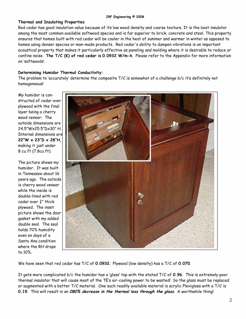
My humidor is con-
structed of cedar over
plywood with the final
layer being a cherry
wood veneer. The
outside dimensions are
24.5”Wx25.5”Dx30” H.
Internal dimensions are
22”W x 23”D x 28”H,
making it just under
8 cu ft (7.8cu ft).
The picture shows my
humidor. It was built
in Tennessee about 16
years ago. The outside
is cherry wood veneer
while the inside is
double-lined with red
cedar over ¾” thick
plywood. The inset
picture shows the door
gasket with my added
double seal. The seal
holds 70% humidity
even on days of a
Santa Ana condition
where the RH drops
to 10%.
We have seen that red cedar has T/C of 0.0932. Plywood (low density) has a T/C of 0.070.
It gets more complicated b/c the humidor has a ‘glass’ top with the stated T/C of 0.96. This is extremely poor
thermal insulator that will cause most of the TE’s air-cooling power to be wasted! So the glass must be replaced
or augmented with a better T/C material. One such readily available material is acrylic Plexiglass with a T/C is
0.19. This will result in an 080% decrease in the thermal loss through the glass. A worthwhile thing!
JRF Engineering © 2008
3
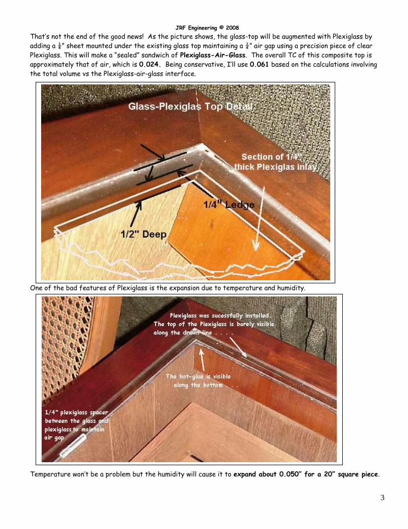
That’s not the end of the good news! As the picture shows, the glass-top will be augmented with Plexiglass by
adding a ¼” sheet mounted under the existing glass top maintaining a ¼” air gap using a precision piece of clear
Plexiglass. This will make a “sealed” sandwich of Plexiglass-Air-Glass. The overall TC of this composite top is
approximately that of air, which is 0.024. Being conservative, I’ll use 0.061 based on the calculations involving
the total volume vs the Plexiglass-air-glass interface.
One of the bad features of Plexiglass is the expansion due to temperature and humidity.
Temperature won’t be a problem but the humidity will cause it to expand about 0.050” for a 20” square piece.
JRF Engineering © 2008
4
This needs to be considered when it’s cut. For 70% RH, apx 3/64” (0.046”) will be subtracted from the desired
dimensions.
The Plexiglass was mounted as shown in the picture above. Everything went as planned with no difficulties other
than the Plexiglass edges were sanded to fit the non-rectangular cabinet. To maintain the ¼” air layer, ¼”
spacers were used as shown above. To secure the Plexiglass, hot-glue from a ‘glue-gun’ was used. The seal is
excellent and it remains flexible in order to take the expansion and contraction of the Plexiglass.
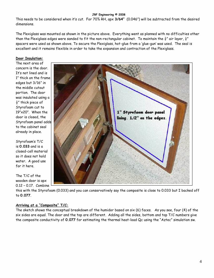
Door Insulation:
The next area of
concern is the door.
It’s not lined and is
1” thick on the frame
edges but 3/16” in
the middle cutout
portion. The door
was insulated using a
½” thick piece of
Styrofoam cut to
19”x20”. When the
door is closed, the
Styrofoam panel adds
to the cabinet seal
already in place.
Styrofoam’s T/C
is 0.033 and is a
closed-cell material
so it does not hold
water. A good use
for it here.
The T/C of the
wooden door is apx
0.12 – 0.17. Combine
this with the Styrofoam (0.033) and you can conservatively say the composite is close to 0.033 but I backed off
to 0.077.
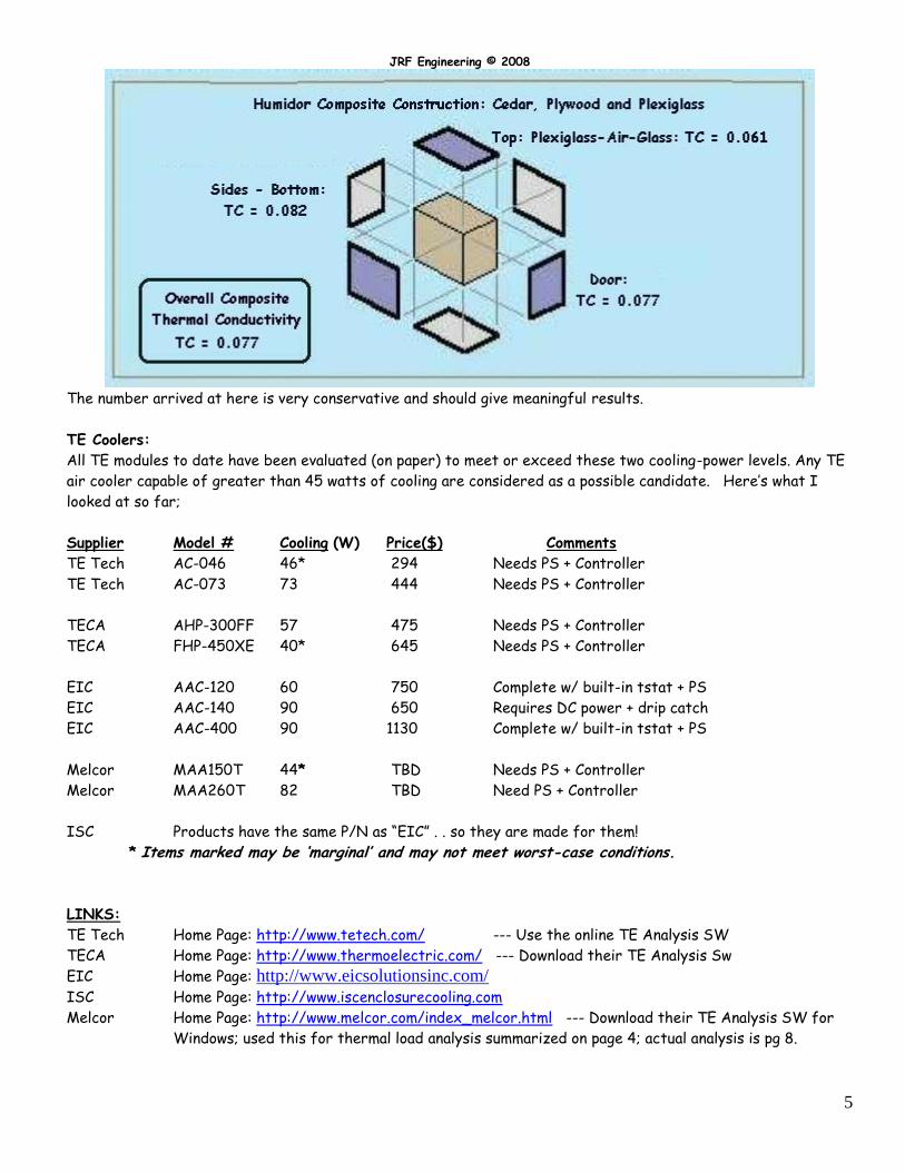
Arriving at a “Composite” T/C:
The sketch shows the conceptual breakdown of the humidor based on six (6) faces. As you see, four (4) of the
six sides are equal. The door and the top are different. Adding all the sides, bottom and top T/C numbers give
the composite conductivity of 0.077 for estimating the thermal heat-load Qc using the “Aztec” simulation sw.
JRF Engineering © 2008
5
The number arrived at here is very conservative and should give meaningful results.
TE Coolers:
All TE modules to date have been evaluated (on paper) to meet or exceed these two cooling-power levels. Any TE
air cooler capable of greater than 45 watts of cooling are considered as a possible candidate. Here’s what I
looked at so far;
Supplier Model # Cooling (W) Price($) Comments
TE Tech AC-046 46* 294 Needs PS + Controller
TE Tech AC-073 73 444 Needs PS + Controller
TECA AHP-300FF 57 475 Needs PS + Controller
TECA FHP-450XE 40* 645 Needs PS + Controller
EIC AAC-120 60 750 Complete w/ built-in tstat + PS
EIC AAC-140 90 650 Requires DC power + drip catch
EIC AAC-400 90 1130 Complete w/ built-in tstat + PS
Melcor MAA150T 44* TBD Needs PS + Controller
Melcor MAA260T 82 TBD Need PS + Controller
ISC Products have the same P/N as “EIC” . . so they are made for them!
* Items marked may be ‘marginal’ and may not meet worst-case conditions.
LINKS:
TE Tech Home Page: http://www.tetech.com/ --- Use the online TE Analysis SW
TECA Home Page: http://www.thermoelectric.com/ --- Download their TE Analysis Sw
EIC Home Page: http://www.eicsolutionsinc.com/
ISC Home Page: http://www.iscenclosurecooling.com
Melcor Home Page: http://www.melcor.com/index_melcor.html --- Download their TE Analysis SW for
Windows; used this for thermal load analysis summarized on page 4; actual analysis is pg 8.
JRF Engineering © 2008
6
Choosing the TE Air Cooler for my Cigar Humidor
After comparing the various TE air coolers from four (4) manufacturers, the products from EIC appear superior
to others. The main reason is the ‘total’ solution involving all fundamental considerations such as the ‘condensate’
drainage. Other manufacturers do not address this and thus become not usable for a cigar humidor application.
The two MAIN problems for a cigar humidor are; maintaining proper humidity (around 70%) and maintaining
proper temperature (normally 70 F).
Two candidates that I have evaluated are the AAC-120-4XT and AAC-140-T. The former is a 200 BTU/hr unit
while the latter is a 400 BTU/hr cooler.
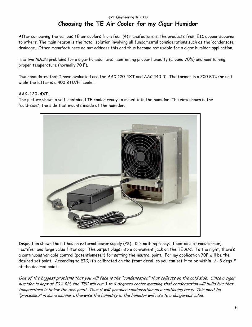
AAC-120-4XT:
The picture shows a self-contained TE cooler ready to mount into the humidor. The view shown is the
“cold-side”, the side that mounts inside of the humidor.
Inspection shows that it has an external power supply (PS). It’s nothing fancy; it contains a transformer,
rectifier and large value filter cap. The output plugs into a convenient jack on the TE A/C. To the right, there’s
a continuous variable control (potentiometer) for setting the neutral point. For my application 70F will be the
desired set point. According to EIC, it’s calibrated on the front decal, so you can set it to be within +/- 3 degs F
of the desired point.
One of the biggest problems that you will face is the “condensation” that collects on the cold side. Since a cigar humidor is kept at 70% RH, the TEC will run 3 to 4 degrees cooler meaning that condensation will build b/c that temperature is below the dew point. Thus it will produce condensation on a continuing basis. This must be “processed” in some manner otherwise the humidity in the humidor will rise to a dangerous value.
JRF Engineering © 2008
7
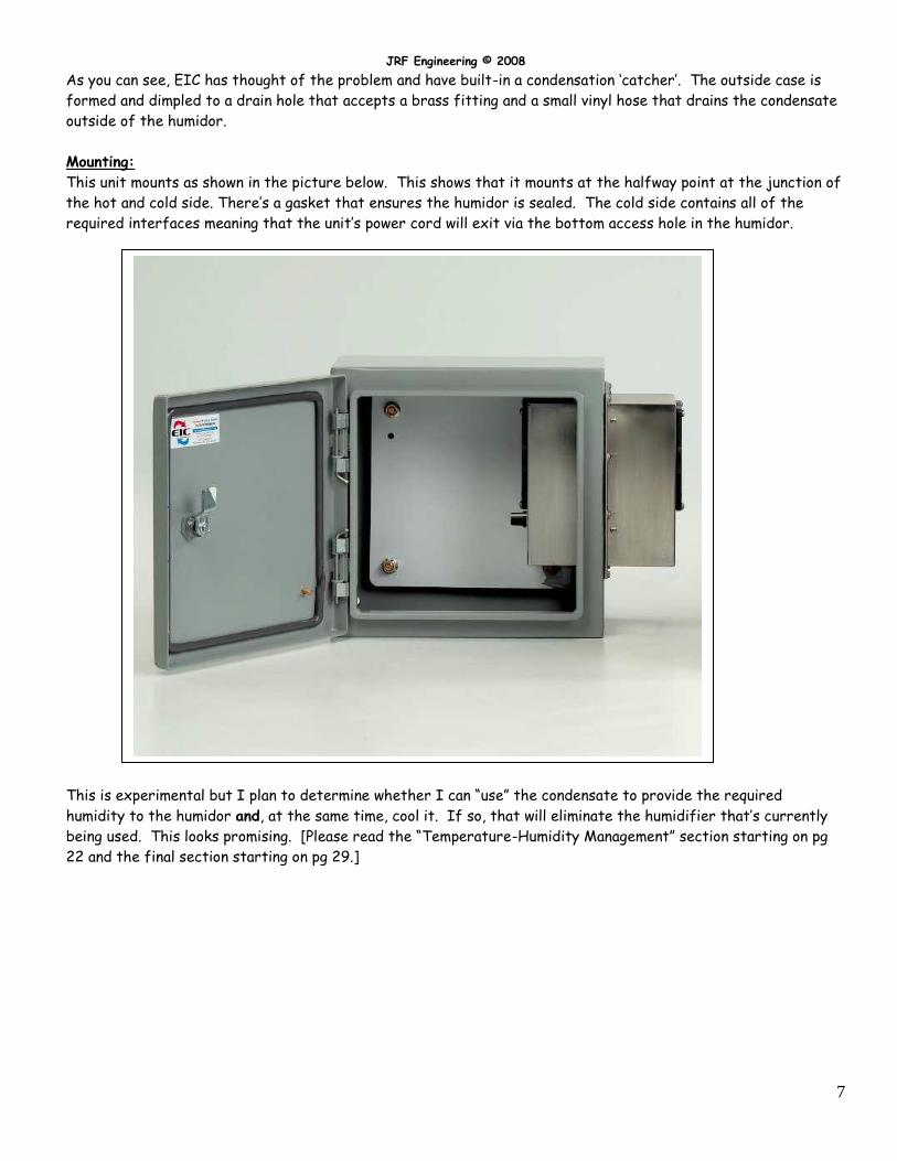
As you can see, EIC has thought of the problem and have built-in a condensation ‘catcher’. The outside case is
formed and dimpled to a drain hole that accepts a brass fitting and a small vinyl hose that drains the condensate
outside of the humidor.
Mounting:
This unit mounts as shown in the picture below. This shows that it mounts at the halfway point at the junction of
the hot and cold side. There’s a gasket that ensures the humidor is sealed. The cold side contains all of the
required interfaces meaning that the unit’s power cord will exit via the bottom access hole in the humidor.
This is experimental but I plan to determine whether I can “use” the condensate to provide the required
humidity to the humidor and, at the same time, cool it. If so, that will eliminate the humidifier that’s currently
being used. This looks promising. [Please read the “Temperature-Humidity Management” section starting on pg
22 and the final section starting on pg 29.]
JRF Engineering © 2008
8
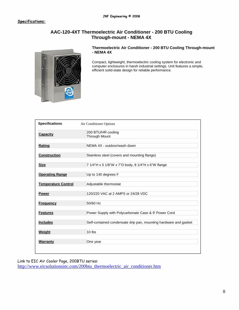
Specifications:
AAC-120-4XT Thermoelectric Air Conditioner - 200 BTU Cooling Through-mount - NEMA 4X
Link to EIC Air Cooler Page, 200BTU series:
http://www.eicsolutionsinc.com/200btu_thermoelectric_air_conditioner.htm
Thermoelectric Air Conditioner - 200 BTU Cooling Through-mount - NEMA 4X
Compact, lightweight, thermoelectric cooling system for electronic and computer enclosures in harsh industrial settings. Unit features a simple, efficient solid-state design for reliable performance.
Specifications Air Conditioner Options
Capacity 200 BTU/HR cooling Through Mount
Rating NEMA 4X - outdoor/wash down
Construction Stainless steel (covers and mounting flange)
Size 7 1/4"H x 5 1/8"W x 7"D body, 8 1/4"H x 6"W flange
Operating Range Up to 140 degrees F
Temperature Control Adjustable thermostat
Power 120/220 VAC at 2 AMPS or 24/28 VDC
Frequency 50/60 Hz
Features Power Supply with Polycarbonate Case & 9' Power Cord
Includes Self-contained condensate drip pan, mounting hardware and gasket
Weight 10 lbs
Warranty One year
JRF Engineering © 2008
9
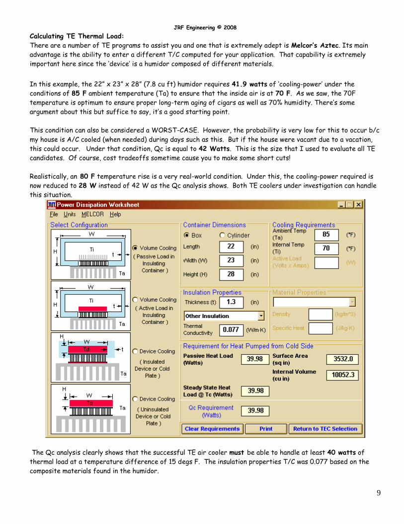
Calculating TE Thermal Load:
There are a number of TE programs to assist you and one that is extremely adept is Melcor’s Aztec. Its main
advantage is the ability to enter a different T/C computed for your application. That capability is extremely
important here since the ‘device’ is a humidor composed of different materials.
In this example, the 22” x 23” x 28” (7.8 cu ft) humidor requires 41.9 watts of ‘cooling-power’ under the
conditions of 85 F ambient temperature (Ta) to ensure that the inside air is at 70 F. As we saw, the 70F
temperature is optimum to ensure proper long-term aging of cigars as well as 70% humidity. There’s some
argument about this but suffice to say, it’s a good starting point.
This condition can also be considered a WORST-CASE. However, the probability is very low for this to occur b/c
my house is A/C cooled (when needed) during days such as this. But if the house were vacant due to a vacation,
this could occur. Under that condition, Qc is equal to 42 Watts. This is the size that I used to evaluate all TE
candidates. Of course, cost tradeoffs sometime cause you to make some short cuts!
Realistically, an 80 F temperature rise is a very real-world condition. Under this, the cooling-power required is
now reduced to 28 W instead of 42 W as the Qc analysis shows. Both TE coolers under investigation can handle
this situation.
The Qc analysis clearly shows that the successful TE air cooler must be able to handle at least 40 watts of
thermal load at a temperature difference of 15 degs F. The insulation properties T/C was 0.077 based on the
composite materials found in the humidor.
JRF Engineering © 2008
10
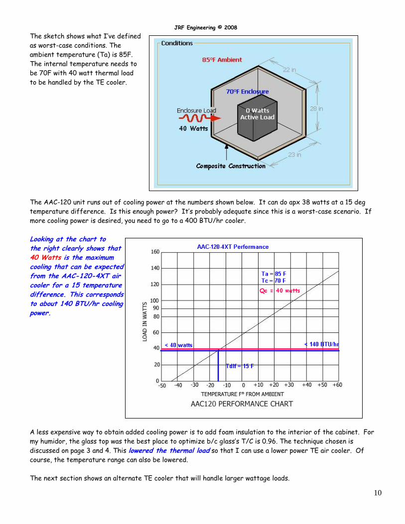
The sketch shows what I’ve defined
as worst-case conditions. The
ambient temperature (Ta) is 85F.
The internal temperature needs to
be 70F with 40 watt thermal load
to be handled by the TE cooler.
The AAC-120 unit runs out of cooling power at the numbers shown below. It can do apx 38 watts at a 15 deg
temperature difference. Is this enough power? It’s probably adequate since this is a worst-case scenario. If
more cooling power is desired, you need to go to a 400 BTU/hr cooler.
Looking at the chart to the right clearly shows that 40 Watts is the maximum cooling that can be expected from the AAC-120-4XT air cooler for a 15 temperature difference. This corresponds to about 140 BTU/hr cooling power.
A less expensive way to obtain added cooling power is to add foam insulation to the interior of the cabinet. For
my humidor, the glass top was the best place to optimize b/c glass’s T/C is 0.96. The technique chosen is
discussed on page 3 and 4. This lowered the thermal load so that I can use a lower power TE air cooler. Of
course, the temperature range can also be lowered.
The next section shows an alternate TE cooler that will handle larger wattage loads.
JRF Engineering © 2008
11
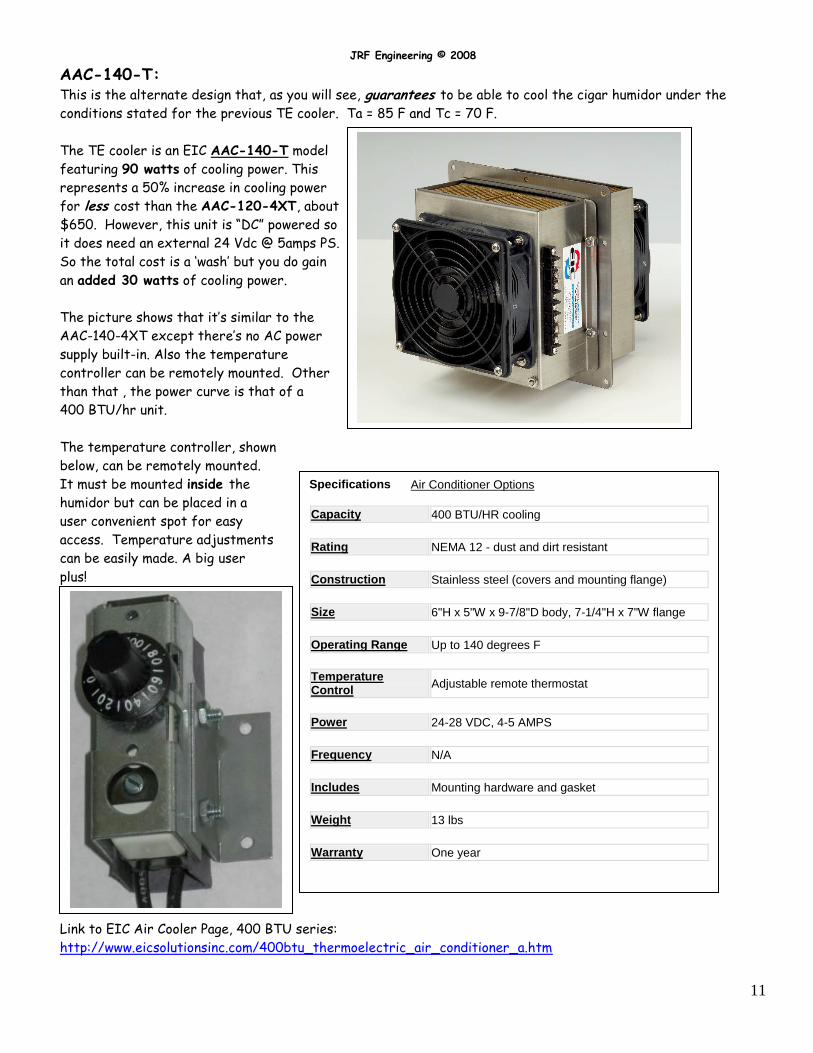
AAC-140-T: This is the alternate design that, as you will see, guarantees to be able to cool the cigar humidor under the
conditions stated for the previous TE cooler. Ta = 85 F and Tc = 70 F.
The TE cooler is an EIC AAC-140-T model
featuring 90 watts of cooling power. This
represents a 50% increase in cooling power
for less cost than the AAC-120-4XT, about
$650. However, this unit is “DC” powered so
it does need an external 24 Vdc @ 5amps PS.
So the total cost is a ‘wash’ but you do gain
an added 30 watts of cooling power.
The picture shows that it’s similar to the
AAC-140-4XT except there’s no AC power
supply built-in. Also the temperature
controller can be remotely mounted. Other
than that , the power curve is that of a
400 BTU/hr unit.
The temperature controller, shown
below, can be remotely mounted.
It must be mounted inside the
humidor but can be placed in a
user convenient spot for easy
access. Temperature adjustments
can be easily made. A big user
plus!
Link to EIC Air Cooler Page, 400 BTU series:
http://www.eicsolutionsinc.com/400btu_thermoelectric_air_conditioner_a.htm
Specifications Air Conditioner Options
Capacity 400 BTU/HR cooling
Rating NEMA 12 - dust and dirt resistant
Construction Stainless steel (covers and mounting flange)
Size 6"H x 5"W x 9-7/8"D body, 7-1/4"H x 7"W flange
Operating Range Up to 140 degrees F
Temperature Control Adjustable remote thermostat
Power 24-28 VDC, 4-5 AMPS
Frequency N/A
Includes Mounting hardware and gasket
Weight 13 lbs
Warranty One year
JRF Engineering © 2008
12
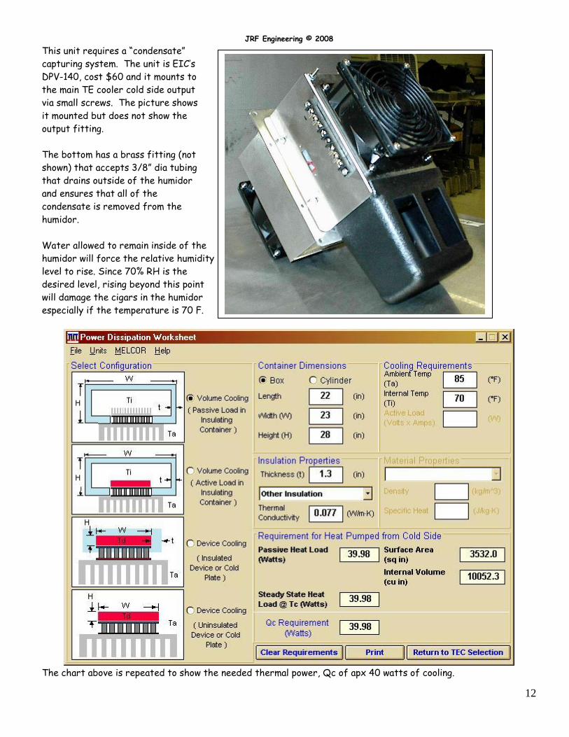
This unit requires a “condensate”
capturing system. The unit is EIC’s
DPV-140, cost $60 and it mounts to
the main TE cooler cold side output
via small screws. The picture shows
it mounted but does not show the
output fitting.
The bottom has a brass fitting (not
shown) that accepts 3/8” dia tubing
that drains outside of the humidor
and ensures that all of the
condensate is removed from the
humidor.
Water allowed to remain inside of the
humidor will force the relative humidity
level to rise. Since 70% RH is the
desired level, rising beyond this point
will damage the cigars in the humidor
especially if the temperature is 70 F.
The chart above is repeated to show the needed thermal power, Qc of apx 40 watts of cooling.
JRF Engineering © 2008
13
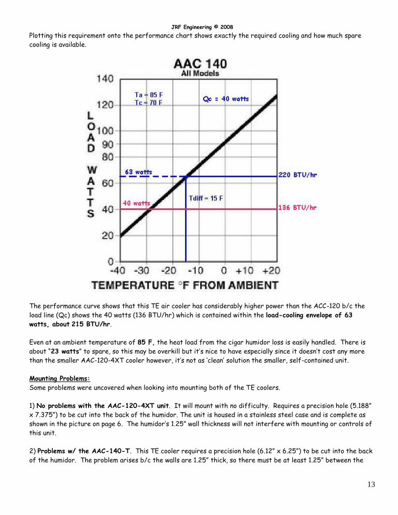
Plotting this requirement onto the performance chart shows exactly the required cooling and how much spare
cooling is available.
The performance curve shows that this TE air cooler has considerably higher power than the ACC-120 b/c the
load line (Qc) shows the 40 watts (136 BTU/hr) which is contained within the load-cooling envelope of 63
watts, about 215 BTU/hr.
Even at an ambient temperature of 85 F, the heat load from the cigar humidor loss is easily handled. There is
about “23 watts” to spare, so this may be overkill but it’s nice to have especially since it doesn’t cost any more
than the smaller AAC-120-4XT cooler however, it’s not as ‘clean’ solution the smaller, self-contained unit.
Mounting Problems:
Some problems were uncovered when looking into mounting both of the TE coolers.
1) No problems with the AAC-120-4XT unit. It will mount with no difficulty. Requires a precision hole (5.188”
x 7.375”) to be cut into the back of the humidor. The unit is housed in a stainless steel case and is complete as
shown in the picture on page 6. The humidor’s 1.25” wall thickness will not interfere with mounting or controls of
this unit.
2) Problems w/ the AAC-140-T. This TE cooler requires a precision hole (6.12” x 6.25”) to be cut into the back
of the humidor. The problem arises b/c the walls are 1.25” thick, so there must be at least 1.25” between the
JRF Engineering © 2008
14
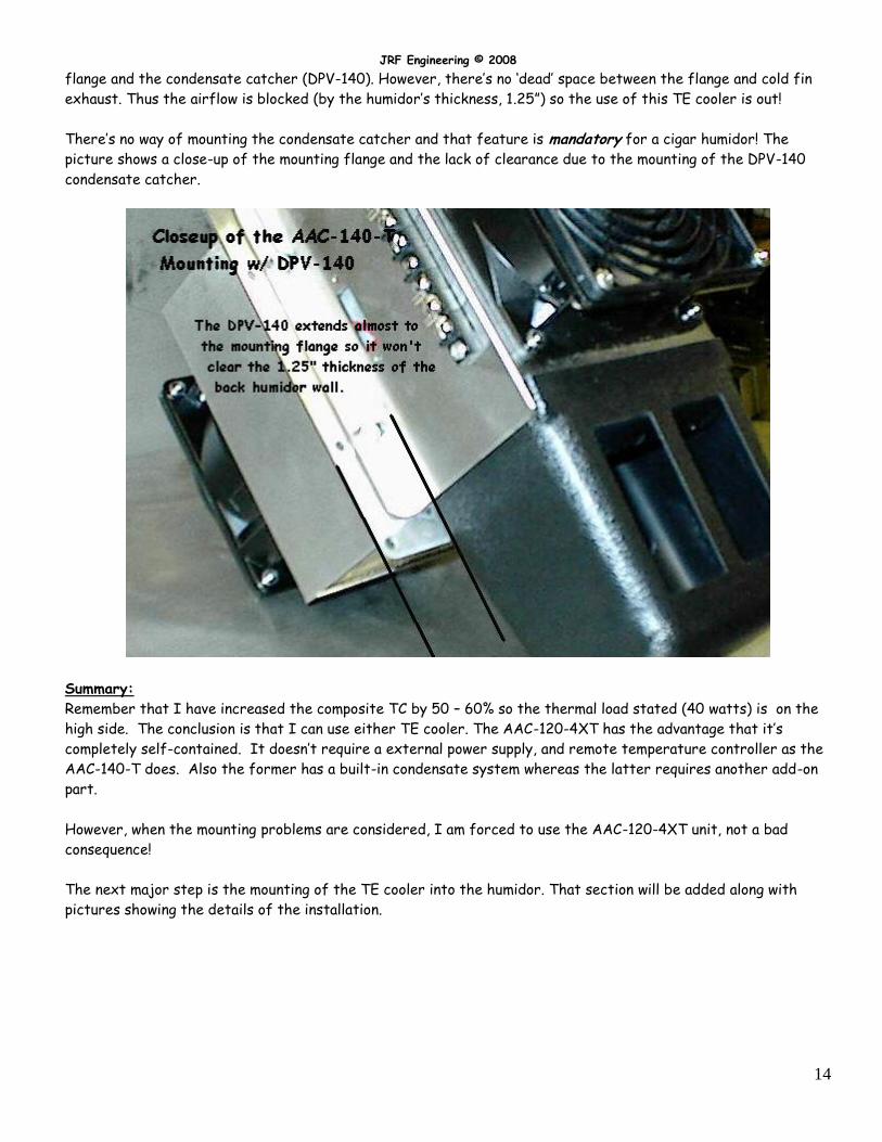
flange and the condensate catcher (DPV-140). However, there’s no ‘dead’ space between the flange and cold fin
exhaust. Thus the airflow is blocked (by the humidor’s thickness, 1.25”) so the use of this TE cooler is out!
There’s no way of mounting the condensate catcher and that feature is mandatory for a cigar humidor! The
picture shows a close-up of the mounting flange and the lack of clearance due to the mounting of the DPV-140
condensate catcher.
Summary:
Remember that I have increased the composite TC by 50 – 60% so the thermal load stated (40 watts) is on the
high side. The conclusion is that I can use either TE cooler. The AAC-120-4XT has the advantage that it’s
completely self-contained. It doesn’t require a external power supply, and remote temperature controller as the
AAC-140-T does. Also the former has a built-in condensate system whereas the latter requires another add-on
part.
However, when the mounting problems are considered, I am forced to use the AAC-120-4XT unit, not a bad
consequence!
The next major step is the mounting of the TE cooler into the humidor. That section will be added along with
pictures showing the details of the installation.
JRF Engineering © 2008
15
Received the “Real-Thing”:
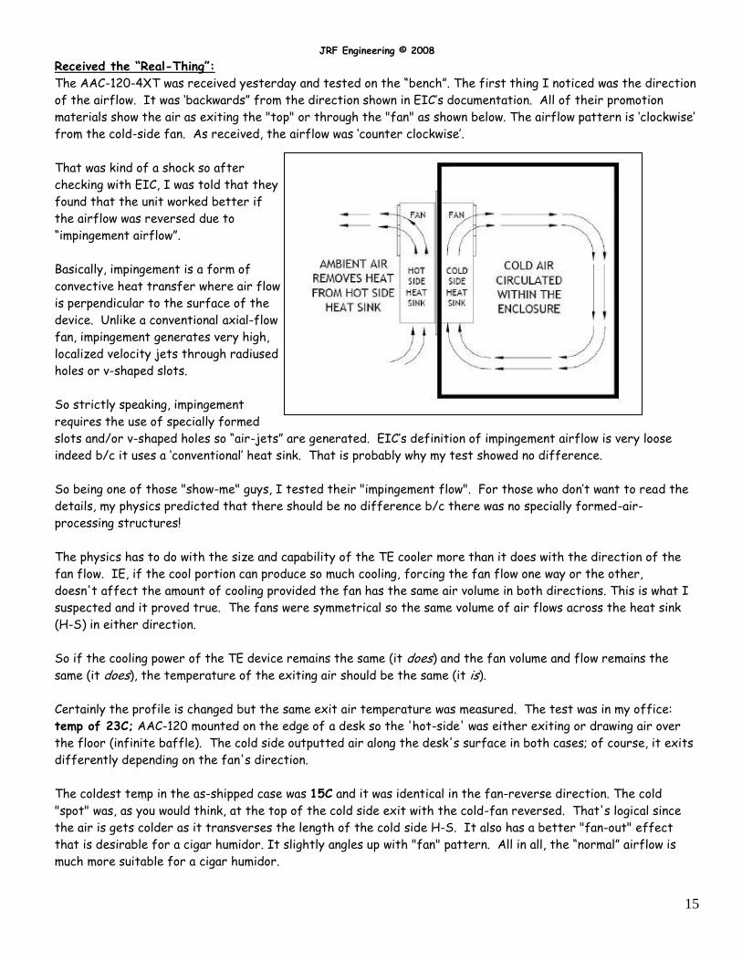
The AAC-120-4XT was received yesterday and tested on the “bench”. The first thing I noticed was the direction
of the airflow. It was ‘backwards” from the direction shown in EIC’s documentation. All of their promotion
materials show the air as exiting the "top" or through the "fan" as shown below. The airflow pattern is ‘clockwise’
from the cold-side fan. As received, the airflow was ‘counter clockwise’.
That was kind of a shock so after
checking with EIC, I was told that they
found that the unit worked better if
the airflow was reversed due to
“impingement airflow”.
Basically, impingement is a form of
convective heat transfer where air flow
is perpendicular to the surface of the
device. Unlike a conventional axial-flow
fan, impingement generates very high,
localized velocity jets through radiused
holes or v-shaped slots.
So strictly speaking, impingement
requires the use of specially formed
slots and/or v-shaped holes so “air-jets” are generated. EIC’s definition of impingement airflow is very loose
indeed b/c it uses a ‘conventional’ heat sink. That is probably why my test showed no difference.
So being one of those "show-me" guys, I tested their "impingement flow". For those who don’t want to read the
details, my physics predicted that there should be no difference b/c there was no specially formed-air-
processing structures!
The physics has to do with the size and capability of the TE cooler more than it does with the direction of the
fan flow. IE, if the cool portion can produce so much cooling, forcing the fan flow one way or the other,
doesn't affect the amount of cooling provided the fan has the same air volume in both directions. This is what I
suspected and it proved true. The fans were symmetrical so the same volume of air flows across the heat sink
(H-S) in either direction.
So if the cooling power of the TE device remains the same (it does) and the fan volume and flow remains the
same (it does), the temperature of the exiting air should be the same (it is).
Certainly the profile is changed but the same exit air temperature was measured. The test was in my office:
temp of 23C; AAC-120 mounted on the edge of a desk so the 'hot-side' was either exiting or drawing air over
the floor (infinite baffle). The cold side outputted air along the desk's surface in both cases; of course, it exits
differently depending on the fan's direction.
The coldest temp in the as-shipped case was 15C and it was identical in the fan-reverse direction. The cold
"spot" was, as you would think, at the top of the cold side exit with the cold-fan reversed. That's logical since
the air is gets colder as it transverses the length of the cold side H-S. It also has a better "fan-out" effect
that is desirable for a cigar humidor. It slightly angles up with "fan" pattern. All in all, the “normal” airflow is
much more suitable for a cigar humidor.
JRF Engineering © 2008
16
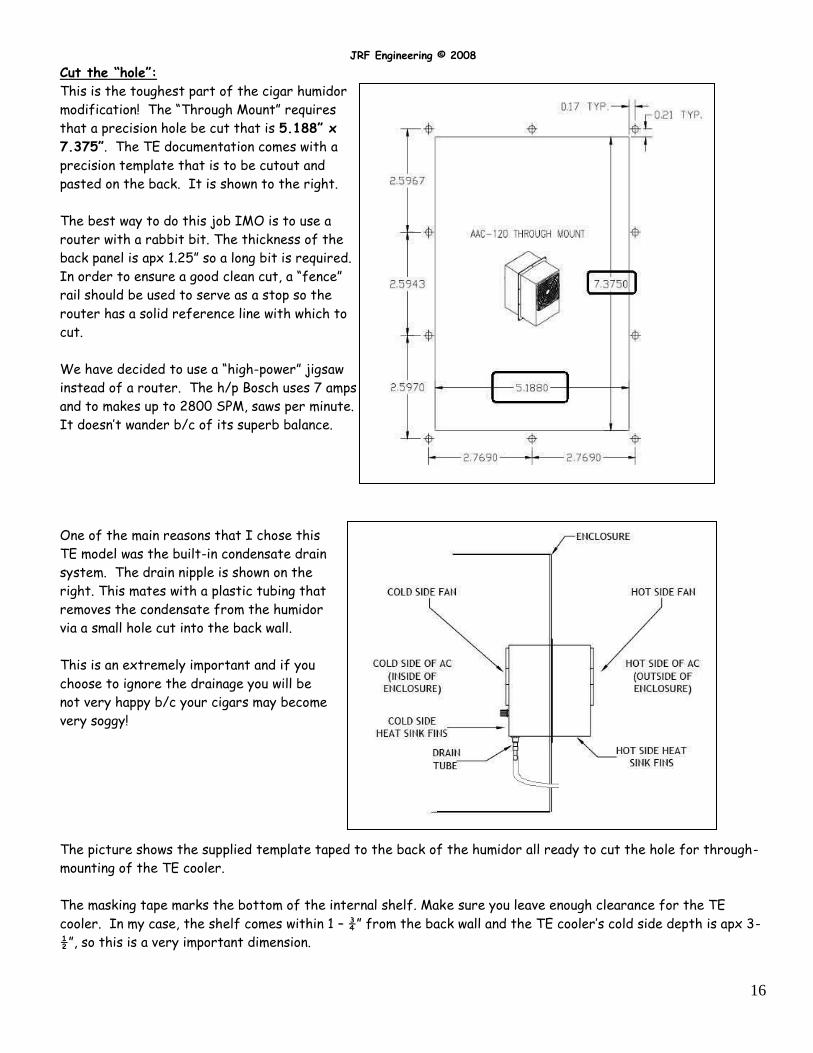
Cut the “hole”:
This is the toughest part of the cigar humidor
modification! The “Through Mount” requires
that a precision hole be cut that is 5.188” x
7.375”. The TE documentation comes with a
precision template that is to be cutout and
pasted on the back. It is shown to the right.
The best way to do this job IMO is to use a
router with a rabbit bit. The thickness of the
back panel is apx 1.25” so a long bit is required.
In order to ensure a good clean cut, a “fence”
rail should be used to serve as a stop so the
router has a solid reference line with which to
cut.
We have decided to use a “high-power” jigsaw
instead of a router. The h/p Bosch uses 7 amps
and to makes up to 2800 SPM, saws per minute.
It doesn’t wander b/c of its superb balance.
One of the main reasons that I chose this
TE model was the built-in condensate drain
system. The drain nipple is shown on the
right. This mates with a plastic tubing that
removes the condensate from the humidor
via a small hole cut into the back wall.
This is an extremely important and if you
choose to ignore the drainage you will be
not very happy b/c your cigars may become
very soggy!
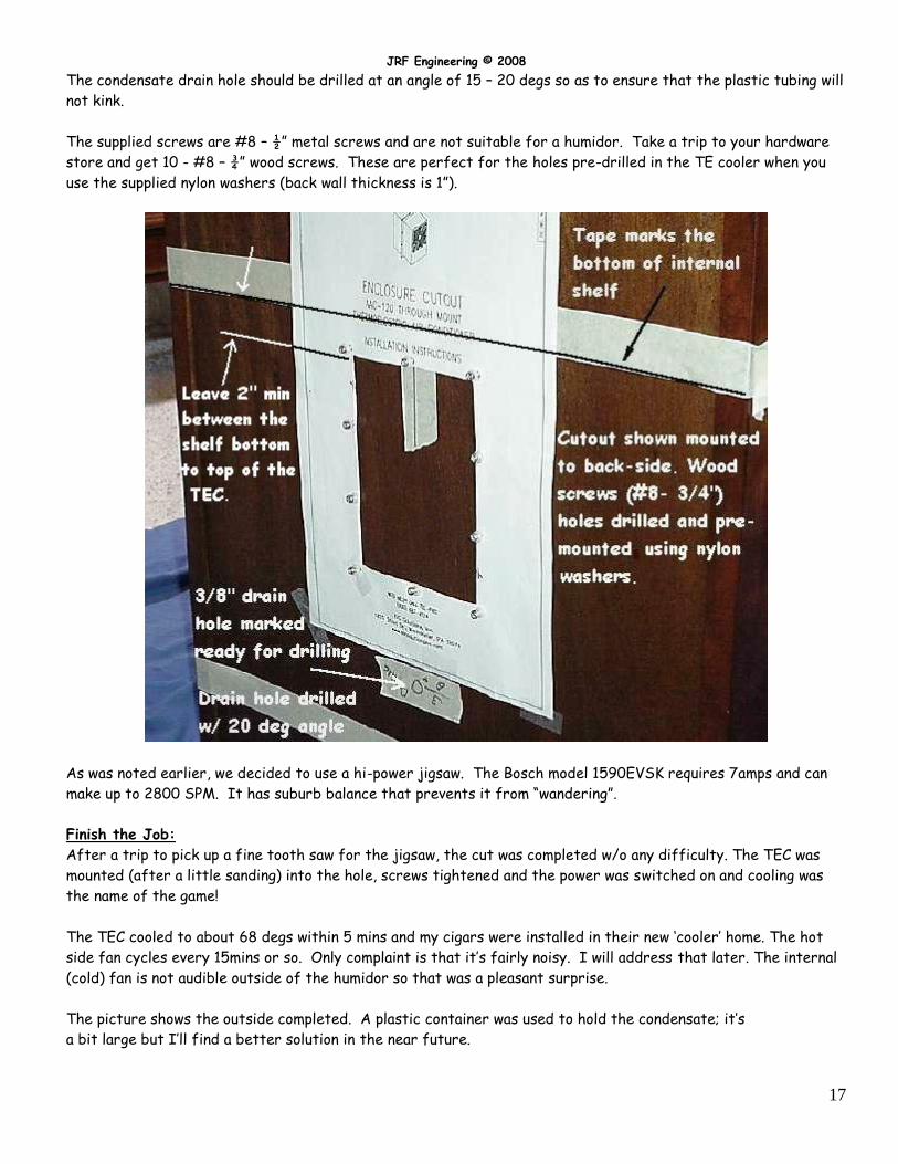
The picture shows the supplied template taped to the back of the humidor all ready to cut the hole for through-
mounting of the TE cooler.
The masking tape marks the bottom of the internal shelf. Make sure you leave enough clearance for the TE
cooler. In my case, the shelf comes within 1 – ¾” from the back wall and the TE cooler’s cold side depth is apx 3-
½”, so this is a very important dimension.
JRF Engineering © 2008
17
The condensate drain hole should be drilled at an angle of 15 – 20 degs so as to ensure that the plastic tubing will
not kink.
The supplied screws are #8 – ½” metal screws and are not suitable for a humidor. Take a trip to your hardware
store and get 10 - #8 – ¾” wood screws. These are perfect for the holes pre-drilled in the TE cooler when you
use the supplied nylon washers (back wall thickness is 1”).
As was noted earlier, we decided to use a hi-power jigsaw. The Bosch model 1590EVSK requires 7amps and can
make up to 2800 SPM. It has suburb balance that prevents it from “wandering”.
Finish the Job:
After a trip to pick up a fine tooth saw for the jigsaw, the cut was completed w/o any difficulty. The TEC was
mounted (after a little sanding) into the hole, screws tightened and the power was switched on and cooling was
the name of the game!
The TEC cooled to about 68 degs within 5 mins and my cigars were installed in their new ‘cooler’ home. The hot
side fan cycles every 15mins or so. Only complaint is that it’s fairly noisy. I will address that later. The internal
(cold) fan is not audible outside of the humidor so that was a pleasant surprise.
The picture shows the outside completed. A plastic container was used to hold the condensate; it’s
a bit large but I’ll find a better solution in the near future.
JRF Engineering © 2008
18
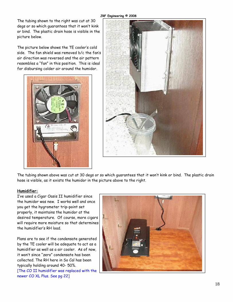
The tubing shown to the right was cut at 30
degs or so which guarantees that it won’t kink
or bind. The plastic drain hose is visible in the
picture below.
The picture below shows the TE cooler’s cold
side. The fan shield was removed b/c the fan’s
air direction was reversed and the air pattern
resembles a “fan” in this position. This is ideal
for disbursing colder air around the humidor.
The tubing shown above was cut at 30 degs or so which guarantees that it won’t kink or bind. The plastic drain
hose is visible, as it exists the humidor in the picture above to the right.
Humidifier:
I’ve used a Cigar Oasis II humidifier since
the humidor was new. I works well and once
you get the hygrometer trip-point set
properly, it maintains the humidor at the
desired temperature. Of course, more cigars
will require more moisture so that determines
the humidifier’s RH load.
Plans are to see if the condensate generated
by the TE cooler will be adequate to act as a
humidifier as well as a air cooler. As of now,
it won’t since “zero” condensate has been
collected. The RH here in So Cal has been
typically holding around 40- 50%.
[The CO II humidifier was replaced with the
newer CO XL Plus. See pg 22]
JRF Engineering © 2008
19
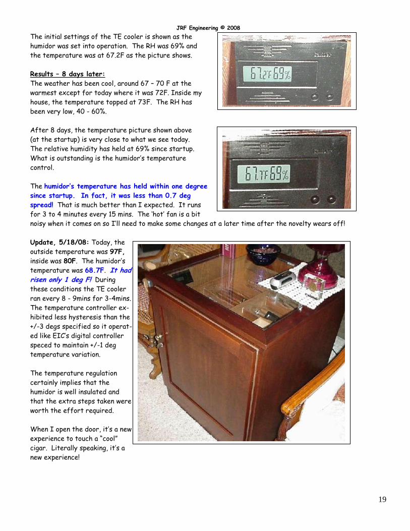
The initial settings of the TE cooler is shown as the
humidor was set into operation. The RH was 69% and
the temperature was at 67.2F as the picture shows.
Results – 8 days later:
The weather has been cool, around 67 – 70 F at the
warmest except for today where it was 72F. Inside my
house, the temperature topped at 73F. The RH has
been very low, 40 - 60%.
After 8 days, the temperature picture shown above
(at the startup) is very close to what we see today.
The relative humidity has held at 69% since startup.
What is outstanding is the humidor’s temperature
control.
The humidor’s temperature has held within one degree
since startup. In fact, it was less than 0.7 deg
spread! That is much better than I expected. It runs
for 3 to 4 minutes every 15 mins. The ‘hot’ fan is a bit
noisy when it comes on so I’ll need to make some changes at a later time after the novelty wears off!
Update, 5/18/08: Today, the
outside temperature was 97F,
inside was 80F. The humidor’s
temperature was 68.7F. It had risen only 1 deg F! During
these conditions the TE cooler
ran every 8 - 9mins for 3-4mins.
The temperature controller ex-
hibited less hysteresis than the
+/-3 degs specified so it operat-
ed like EIC’s digital controller
speced to maintain +/-1 deg
temperature variation.
The temperature regulation
certainly implies that the
humidor is well insulated and
that the extra steps taken were
worth the effort required.
When I open the door, it’s a new
experience to touch a “cool”
cigar. Literally speaking, it’s a
new experience!
JRF Engineering © 2008
20
Hot-Side Fan Noise:
As noted earlier, the hot-side fan noise is fairly high and can easily be heard across the room. So the time has
come to do something to reduce it.
The fans (both hot and cold) are made by YS Tech [http://ystechusa.com/dc120series.html]. After
investigating, I found that their fans are usually noisier than other fans (Papst or Nexus) but have a very long
life. Both features are important but for my application, I favor less noise even if some operational life is the
trade-off.
The hot/cold fans that EIC uses are 120mm x 120mm x 25mm. Here’s is the specs:
Inspection of the chart shows that a “L” fan is 10dB quieter than a “H” version. H= Hi Speed; L= Lo Speed. If
the present fan speed was reduced from 2600 to 1800, that should significantly lower the present noise, 44dB to
34dB, a difference of 10dB. However, the CFM will be reduced by apx 25% to 73CFM. It remains to be seen
what effect it will have on the TE cooler’s operation.
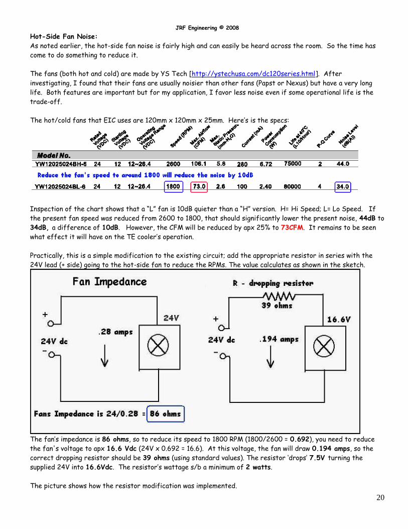
Practically, this is a simple modification to the existing circuit; add the appropriate resistor in series with the
24V lead (+ side) going to the hot-side fan to reduce the RPMs. The value calculates as shown in the sketch.
The fan’s impedance is 86 ohms, so to reduce its speed to 1800 RPM (1800/2600 = 0.692), you need to reduce
the fan's voltage to apx 16.6 Vdc (24V x 0.692 = 16.6). At this voltage, the fan will draw 0.194 amps, so the
correct dropping resistor should be 39 ohms (using standard values). The resistor ‘drops’ 7.5V turning the
supplied 24V into 16.6Vdc. The resistor’s wattage s/b a minimum of 2 watts.
The picture shows how the resistor modification was implemented.
JRF Engineering © 2008
21
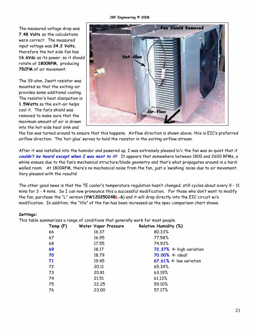
The measured voltage drop was
7.48 Volts so the calculations
were correct. The measured
input voltage was 24.2 Volts,
therefore the hot side fan has
16.6Vdc as its power, so it should
rotate at 1800RPM, producing
75CFM of air movement.
The 39-ohm, 2watt resistor was
mounted so that the exiting-air
provides some additional cooling.
The resistor’s heat dissipation is
1.5Watts so the exit-air helps
cool it. The fan’s shield was
removed to make sure that the
maximum amount of air is drawn
into the hot-side heat sink and
the fan was turned around to ensure that this happens. Airflow direction is shown above; this is EIC’s preferred
airflow direction. The ‘hot-glue’ serves to hold the resistor in the exiting airflow stream.
After it was installed into the humidor and powered up, I was extremely pleased b/c the fan was so quiet that it
couldn’t be heard except when I was next to it! It appears that somewhere between 1800 and 2600 RPMs, a
whine ensues due to the fan’s mechanical structure/blade geometry and that’s what propagates around in a hard-
walled room. At 1800RPM, there’s no mechanical noise from the fan, just a ‘swishing’ noise due to air movement.
Very pleased with the results!
The other good news is that the TE cooler’s temperature regulation hasn’t changed; still cycles about every 9 - 11
mins for 3 - 4 mins. So I can now pronounce this a successful modification. For those who don’t want to modify
the fan, purchase the “L” version (YW12025024BL-6) and it will drop directly into the EIC circuit w/o
modification. In addition, the “life” of the fan has been increased as the spec comparison chart shows.
Settings:
This table summarizes a range of conditions that generally work for most people.
Temp (F) Water Vapor Pressure Relative Humidity (%)
66 16.37 80.33%
67 16.95 77.58%
68 17.55 74.93%
69 18.17 72.37% high variation
70 18.79 70.00% ideal!
71 19.45 67.61% low variation
72 20.11 65.39%
73 20.81 63.19%
74 21.51 61.13%
75 22.25 59.10%
76 23.00 57.17%
JRF Engineering © 2008
22
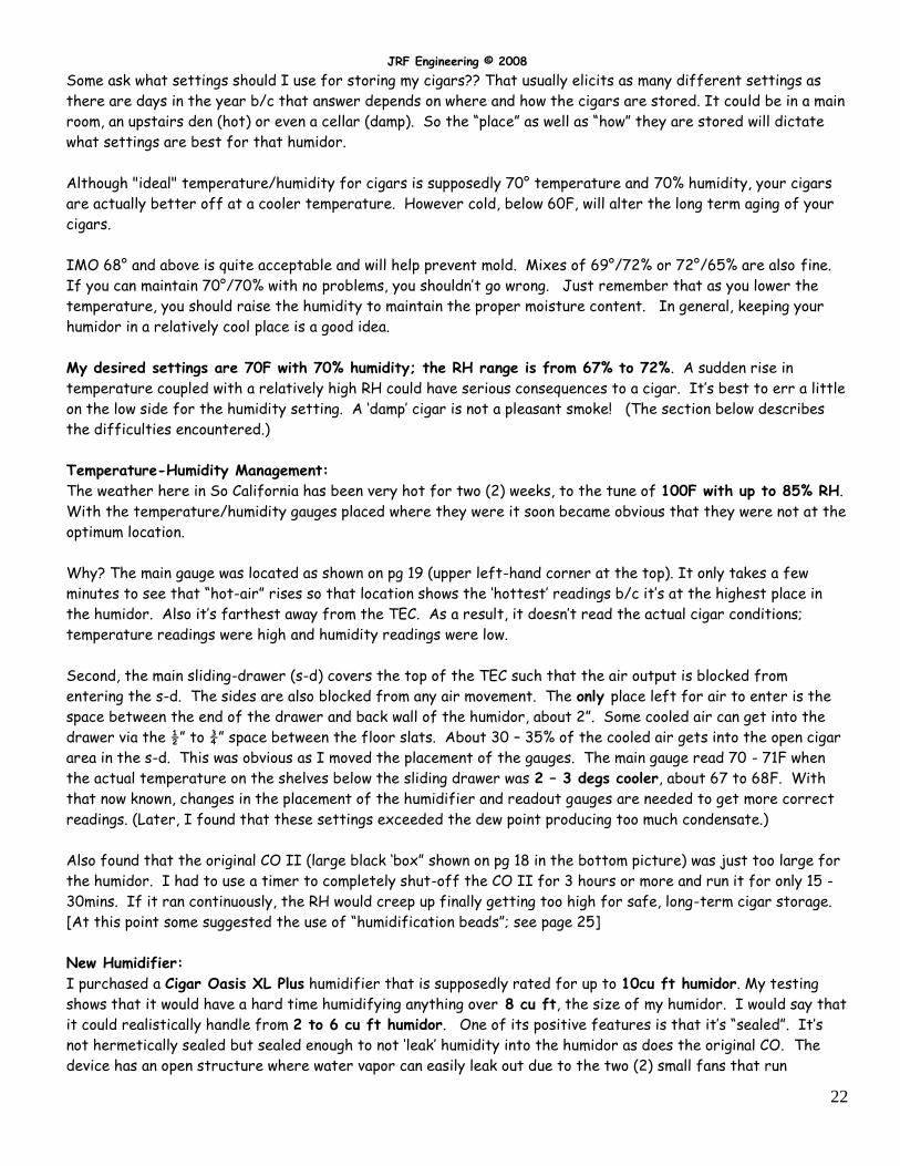
Some ask what settings should I use for storing my cigars?? That usually elicits as many different settings as
there are days in the year b/c that answer depends on where and how the cigars are stored. It could be in a main
room, an upstairs den (hot) or even a cellar (damp). So the “place” as well as “how” they are stored will dictate
what settings are best for that humidor.
Although "ideal" temperature/humidity for cigars is supposedly 70° temperature and 70% humidity, your cigars
are actually better off at a cooler temperature. However cold, below 60F, will alter the long term aging of your
cigars.
IMO 68° and above is quite acceptable and will help prevent mold. Mixes of 69°/72% or 72°/65% are also fine.
If you can maintain 70°/70% with no problems, you shouldn’t go wrong. Just remember that as you lower the
temperature, you should raise the humidity to maintain the proper moisture content. In general, keeping your
humidor in a relatively cool place is a good idea.
My desired settings are 70F with 70% humidity; the RH range is from 67% to 72%. A sudden rise in
temperature coupled with a relatively high RH could have serious consequences to a cigar. It’s best to err a little
on the low side for the humidity setting. A ‘damp’ cigar is not a pleasant smoke! (The section below describes
the difficulties encountered.)
Temperature-Humidity Management:
The weather here in So California has been very hot for two (2) weeks, to the tune of 100F with up to 85% RH.
With the temperature/humidity gauges placed where they were it soon became obvious that they were not at the
optimum location.
Why? The main gauge was located as shown on pg 19 (upper left-hand corner at the top). It only takes a few
minutes to see that “hot-air” rises so that location shows the ‘hottest’ readings b/c it’s at the highest place in
the humidor. Also it’s farthest away from the TEC. As a result, it doesn’t read the actual cigar conditions;
temperature readings were high and humidity readings were low.
Second, the main sliding-drawer (s-d) covers the top of the TEC such that the air output is blocked from
entering the s-d. The sides are also blocked from any air movement. The only place left for air to enter is the
space between the end of the drawer and back wall of the humidor, about 2”. Some cooled air can get into the
drawer via the ½” to ¾” space between the floor slats. About 30 – 35% of the cooled air gets into the open cigar
area in the s-d. This was obvious as I moved the placement of the gauges. The main gauge read 70 - 71F when
the actual temperature on the shelves below the sliding drawer was 2 – 3 degs cooler, about 67 to 68F. With
that now known, changes in the placement of the humidifier and readout gauges are needed to get more correct
readings. (Later, I found that these settings exceeded the dew point producing too much condensate.)
Also found that the original CO II (large black ‘box” shown on pg 18 in the bottom picture) was just too large for
the humidor. I had to use a timer to completely shut-off the CO II for 3 hours or more and run it for only 15 -
30mins. If it ran continuously, the RH would creep up finally getting too high for safe, long-term cigar storage.
[At this point some suggested the use of “humidification beads”; see page 25]
New Humidifier:
I purchased a Cigar Oasis XL Plus humidifier that is supposedly rated for up to 10cu ft humidor. My testing
shows that it would have a hard time humidifying anything over 8 cu ft, the size of my humidor. I would say that
it could realistically handle from 2 to 6 cu ft humidor. One of its positive features is that it’s “sealed”. It’s
not hermetically sealed but sealed enough to not ‘leak’ humidity into the humidor as does the original CO. The
device has an open structure where water vapor can easily leak out due to the two (2) small fans that run
JRF Engineering © 2008
23
continuously affecting the RH of the humidor even though the microprocessor is not calling to run the main fan.
The XL Plus completely stops its fan and so there’s minimal leakage if any.
However, it is this structure that causes a problem. The large open area in the center of the water fill tray is located directly under the recirculation fan. The fan is shut-off when the RH is below the set point but the internal RH sensor is still active. So its problematic that it will indicate a higher amount of humidity than is truly present outside the CO’s case. Typically it reads 2-3% higher. Once you know this, you can easily compensate for it. It could be compensated for in the design.
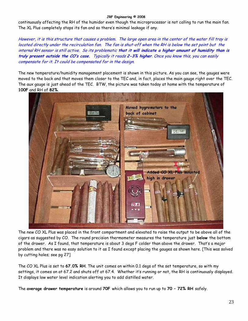
The new temperature/humidity management placement is shown in this picture. As you can see, the gauges were
moved to the back and that moves them closer to the TEC and, in fact, places the main gauge right over the TEC.
The aux gauge is just ahead of the TEC. BTW, the picture was taken today at home with the temperature of
100F and RH of 82%.
The new CO XL Plus was placed in the front compartment and elevated to raise the output to be above all of the
cigars as suggested by CO. The round precision thermometer measures the temperature just below the bottom
of the drawer. As I found, that temperature is about 3 degs F colder than above the drawer. That’s a major
problem and there was no easy solution to it as I found except placing the gauges as shown here. [This was solved
by cutting holes; see pg 27]
The CO XL Plus is set to 67.0% RH. The unit comes on within 0.1 degs of the set temperature, so with my
settings, it comes on at 67.2 and shuts off at 67.4. Whether it’s running or not, the RH is continuously displayed.
It displays low water level indication alerting you to add distilled water.
The average drawer temperature is around 70F which allows you to run up to 70 – 72% RH safely.
JRF Engineering © 2008
24
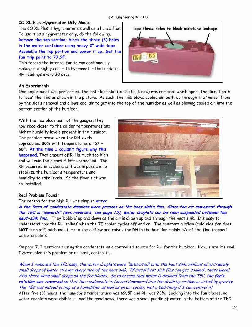
CO XL Plus Hygrometer Only Mode:
The CO XL Plus is hygrometer as well as a humidifier.
To use it as a hygrometer only, do the following.
Remove the top section; block the three (3) holes
in the water container using heavy 2” wide tape.
Assemble the top portion and power it up. Set the
fan trip point to 79.9F.
This forces the internal fan to run continuously
making it a highly accurate hygrometer that updates
RH readings every 30 secs.
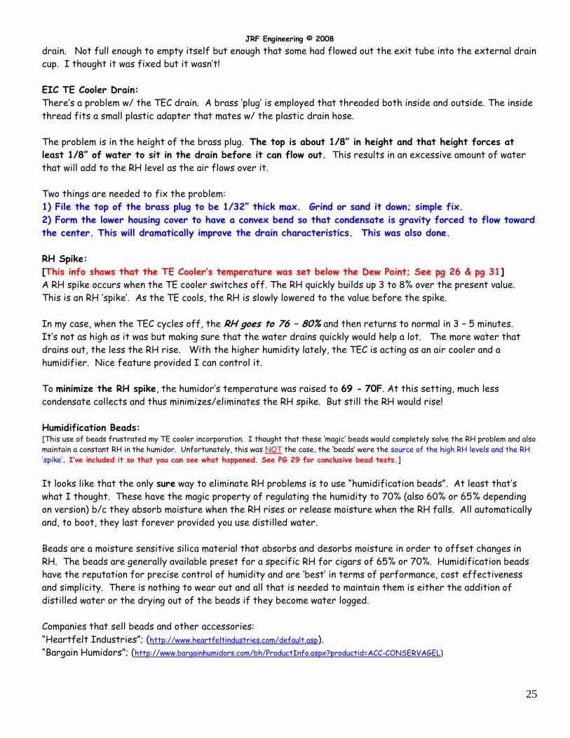
An Experiment:
One experiment was performed: the last floor slot (in the back row) was removed which opens the direct path
to “see” the TEC as shown in the picture. As such, the TEC blows cooled air both up through the “holes” from
by the slot’s removal and allows cool air to get into the top of the humidor as well as blowing cooled air into the
bottom section of the humidor.
With the new placement of the gauges, they
now read closer to the colder temperatures and
higher humidity levels present in the humidor.
The problem arose when the RH levels
approached 80% with temperatures of 67 –
68F. At the time I couldn’t figure why this
happened. That amount of RH is much too high
and will ruin the cigars if left unchecked. The
RH occurred in cycles and it was impossible to
stabilize the humidor’s temperature and
humidity to safe levels. So the floor slat was
re-installed.
Real Problem Found:
The reason for the high RH was simple: water in the form of condensate droplets were present on the heat sink’s fins. Since the air movement through the TEC is “upwards” (was reversed, see page 15), water droplets can be seen suspended between the heat-sink fins. They ‘bobble’ up and down as the air is drawn up and through the heat sink. It’s easy to
understand how the RH ‘spikes’ when the TE cooler cycles off and on. The constant airflow (cold side fan does
NOT turn off) adds moisture to the airflow and raises the RH in the humidor mainly b/c of the fine trapped
water droplets.
On page 7, I mentioned using the condensate as a controlled source for RH for the humidor. Now, since it’s real,
I must solve this problem or at least, control it.
When I removed the TEC assy, the water droplets were “saturated” onto the heat sink; millions of extremely small drops of water all over every inch of the heat sink. If metal heat sink fins can get ‘soaked’, these were! Also there were small drops on the fan blades. So to ensure that water is drained from the TEC, the fan’s rotation was reversed so that the condensate is forced downward into the drain by airflow assisted by gravity. The TEC was indeed acting as a humidifier as well as an air cooler. Not a bad thing if I can control it! After five (3) hours, the humidor’s temperature was 69.5F and RH was 73%. Looking into the fan blades, no
water droplets were visible . . . and the good news, there was a small puddle of water in the bottom of the TEC
JRF Engineering © 2008
25
drain. Not full enough to empty itself but enough that some had flowed out the exit tube into the external drain
cup. I thought it was fixed but it wasn’t!
EIC TE Cooler Drain:
There’s a problem w/ the TEC drain. A brass ‘plug’ is employed that threaded both inside and outside. The inside
thread fits a small plastic adapter that mates w/ the plastic drain hose.
The problem is in the height of the brass plug. The top is about 1/8” in height and that height forces at
least 1/8” of water to sit in the drain before it can flow out. This results in an excessive amount of water
that will add to the RH level as the air flows over it.
Two things are needed to fix the problem:
1) File the top of the brass plug to be 1/32” thick max. Grind or sand it down; simple fix.
2) Form the lower housing cover to have a convex bend so that condensate is gravity forced to flow toward
the center. This will dramatically improve the drain characteristics. This was also done.
RH Spike:
[This info shows that the TE Cooler’s temperature was set below the Dew Point; See pg 26 & pg 31]
A RH spike occurs when the TE cooler switches off. The RH quickly builds up 3 to 8% over the present value.
This is an RH ‘spike’. As the TE cools, the RH is slowly lowered to the value before the spike.
In my case, when the TEC cycles off, the RH goes to 76 – 80% and then returns to normal in 3 – 5 minutes.
It’s not as high as it was but making sure that the water drains quickly would help a lot. The more water that
drains out, the less the RH rise. With the higher humidity lately, the TEC is acting as an air cooler and a
humidifier. Nice feature provided I can control it.
To minimize the RH spike, the humidor’s temperature was raised to 69 - 70F. At this setting, much less
condensate collects and thus minimizes/eliminates the RH spike. But still the RH would rise!
Humidification Beads: [This use of beads frustrated my TE cooler incorporation. I thought that these ‘magic’ beads would completely solve the RH problem and also
maintain a constant RH in the humidor. Unfortunately, this was NOT the case, the ‘beads’ were the source of the high RH levels and the RH
‘spike’. I’ve included it so that you can see what happened. See PG 29 for conclusive bead tests.]
It looks like that the only sure way to eliminate RH problems is to use “humidification beads”. At least that’s
what I thought. These have the magic property of regulating the humidity to 70% (also 60% or 65% depending
on version) b/c they absorb moisture when the RH rises or release moisture when the RH falls. All automatically
and, to boot, they last forever provided you use distilled water.
Beads are a moisture sensitive silica material that absorbs and desorbs moisture in order to offset changes in
RH. The beads are generally available preset for a specific RH for cigars of 65% or 70%. Humidification beads
have the reputation for precise control of humidity and are ‘best’ in terms of performance, cost effectiveness
and simplicity. There is nothing to wear out and all that is needed to maintain them is either the addition of
distilled water or the drying out of the beads if they become water logged.
Companies that sell beads and other accessories:
“Heartfelt Industries”; (http://www.heartfeltindustries.com/default.asp).
“Bargain Humidors”; (http://www.bargainhumidors.com/bh/ProductInfo.aspx?productid=ACC-CONSERVAGEL)
JRF Engineering © 2008
26
An 8 cu ft humidor requires about 1.75 lbs of beads for passive humidification. I was told: when a TE cooler is employed, you may need to double the amount of beads to minimize the RH spike. I started with 1lb with little
success. So another 1lb was added of 65% beads and mixed with the 70% making a composite of 68%. These
were added to a shallow stainless steel pan with dimensions of 19” x 12” x 1.5”. The bead depth is about ½”. The
less depth the better since more beads are in contact w/ the humidified air. For my application, no distilled
water was added. Placed the pan into the humidor and you should be all set.
With the TE cooler set to 67F (69F as measured in the drawer), I started to see a rise in RH after a few
minutes. [This was the clue but I didn’t see it until later; see pg 29] It rose to 75% and it was ‘real’; all
three “gauges”, showed the increase. At first, I thought that the TE cooler was the cause of the condensate but
after checking, it was completely dry. But there WAS an increase in ‘water-vapor’ that caused the RH rise! The
RH was running consistently over 73%, sometimes getting to 77%.
Finally A Real Solution (8/8/08):
We have been still been experiencing some high humidity days (80 - 85%) in So Cal and the humidor’s RH has
risen to levels that had me concerned; around 75 - 77%. So it’s time to solve this problem permanently!
First let’s make sure we all understand what condensate means! It’s nothing more than the definition of Dew
Point (D/P). D/P is that temperature where the water vapor contained in the air “comes” out in the form of
water b/c the air is saturated and can no longer hold the water vapor.
RH and D/P are closely related and are based upon the amount of water vapor in the air and the total amount of
water vapor that the air can hold at a given temperature. The warmer the air, the more water vapor it can
contain. Conversely, the cooler the air, the less vapor it can contain. This is why moisture condenses on a cold
glass. As the air near the object cools, it reaches the point where it can’t contain all the water which it held at a
warmer temperature and some moisture is drawn out of the air.
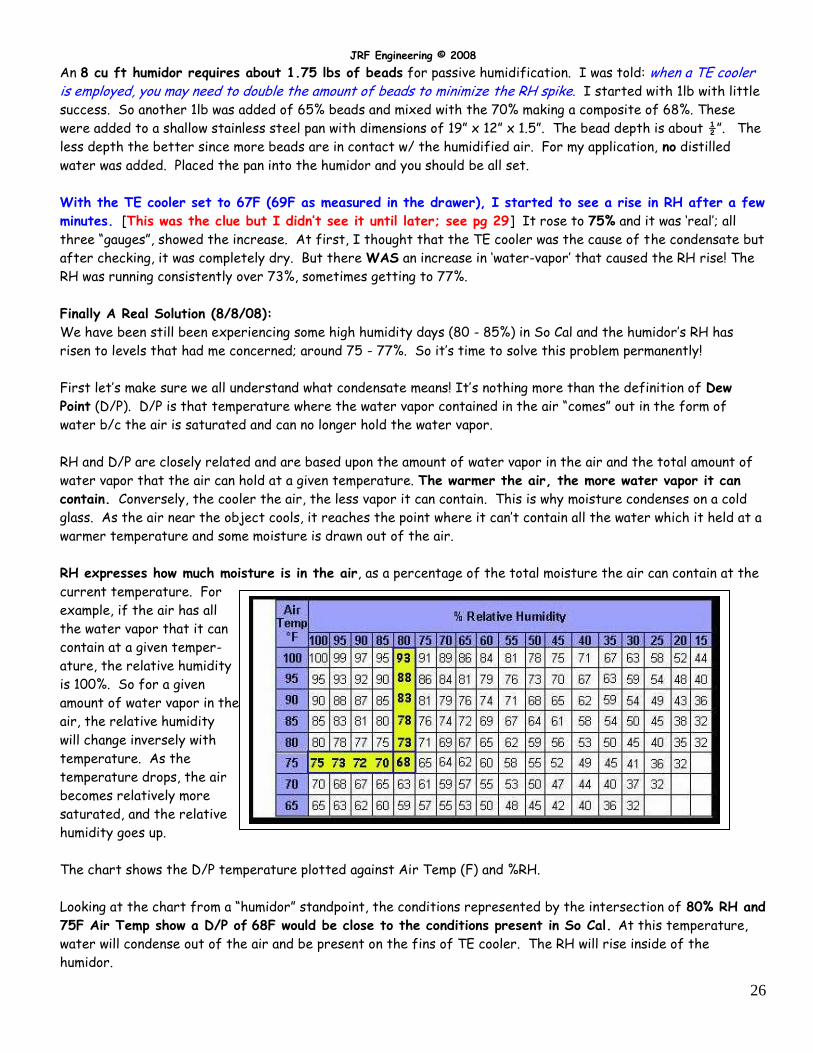
RH expresses how much moisture is in the air, as a percentage of the total moisture the air can contain at the
current temperature. For
example, if the air has all
the water vapor that it can
contain at a given temper-
ature, the relative humidity
is 100%. So for a given
amount of water vapor in the
air, the relative humidity
will change inversely with
temperature. As the
temperature drops, the air
becomes relatively more
saturated, and the relative
humidity goes up.
The chart shows the D/P temperature plotted against Air Temp (F) and %RH.
Looking at the chart from a “humidor” standpoint, the conditions represented by the intersection of 80% RH and
75F Air Temp show a D/P of 68F would be close to the conditions present in So Cal. At this temperature,
water will condense out of the air and be present on the fins of TE cooler. The RH will rise inside of the
humidor.
JRF Engineering © 2008
27
So the ‘trick’ is to set the TE cooler temperature to be higher than the D/P temperature, 68F in this
example. Set it to, say 70F. This should give you a safe margin even if the temperature rises.
Setting the TE cooler to 70F means that the humidor will, most likely, be around 71 - 72F. Using the chart on pg
21, the desired RH would be 65 - 67%.
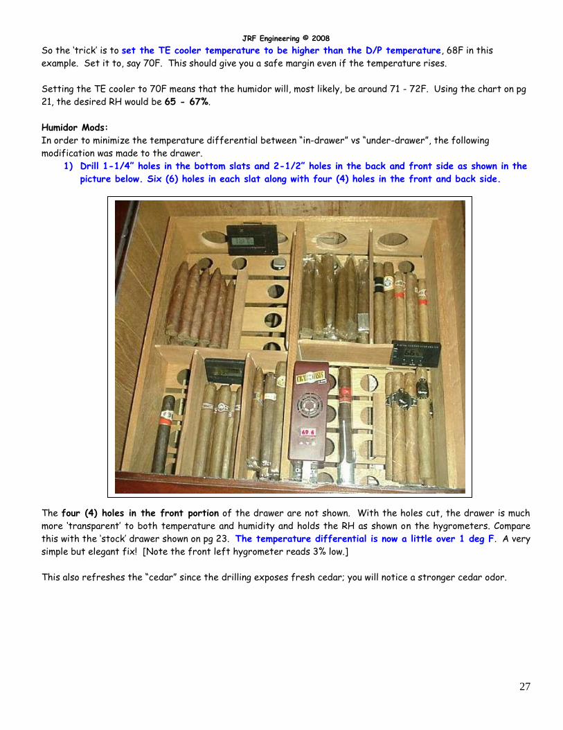
Humidor Mods:
In order to minimize the temperature differential between “in-drawer” vs “under-drawer”, the following
modification was made to the drawer.
1) Drill 1-1/4” holes in the bottom slats and 2-1/2” holes in the back and front side as shown in the
picture below. Six (6) holes in each slat along with four (4) holes in the front and back side.
The four (4) holes in the front portion of the drawer are not shown. With the holes cut, the drawer is much
more ‘transparent’ to both temperature and humidity and holds the RH as shown on the hygrometers. Compare
this with the ‘stock’ drawer shown on pg 23. The temperature differential is now a little over 1 deg F. A very
simple but elegant fix! [Note the front left hygrometer reads 3% low.]
This also refreshes the “cedar” since the drilling exposes fresh cedar; you will notice a stronger cedar odor.
JRF Engineering © 2008
28
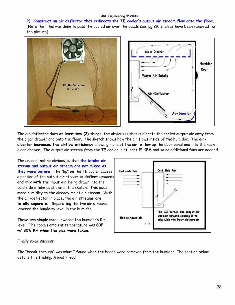
2) Construct an air deflector that redirects the TE cooler’s output air stream flow onto the floor.
[Note that this was done to pass the cooled air over the beads see, pg 29; shelves have been removed for
the picture]
The air deflector does at least two (2) things: the obvious is that it directs the cooled output air away from
the cigar drawer and onto the floor. The sketch shows how the air flows inside of the humidor. The air-
diverter increases the airflow efficiency allowing more of the air to flow up the door panel and into the main
cigar drawer. The output air stream from the TE cooler is at least 15 CFM and so no additional fans are needed.
The second, not so obvious, is that the intake air
stream and output air stream are not mixed as
they were before. The “lip” on the TE cooler causes
a portion of the output air stream to deflect upwards
and mix with the input air being drawn into the
cold side intake as shown in the sketch. This adds
more humidity to the already moist air stream. With
the air-deflector in place, the air streams are
totally separate. Separating the two air streams
lowered the humidity level in the humidor.
These two simple mods lowered the humidor’s RH
level. The room’s ambient temperature was 80F
w/ 80% RH when the pics were taken.
Finally some success!
The “break-through” was what I found when the beads were removed from the humidor. The section below
details this finding. A must-read.
JRF Engineering © 2008
29
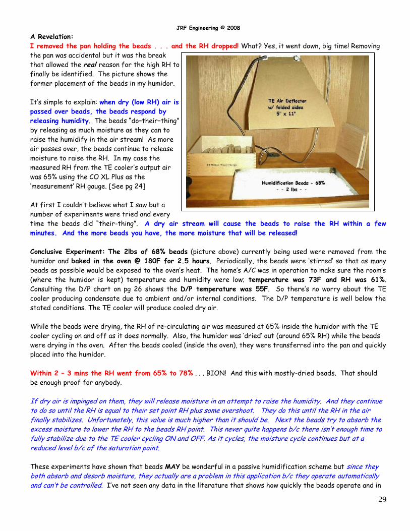
A Revelation:
I removed the pan holding the beads . . . and the RH dropped! What? Yes, it went down, big time! Removing
the pan was accidental but it was the break
that allowed the real reason for the high RH to
finally be identified. The picture shows the
former placement of the beads in my humidor.
It’s simple to explain: when dry (low RH) air is
passed over beads, the beads respond by
releasing humidity. The beads “do–their–thing”
by releasing as much moisture as they can to
raise the humidify in the air stream! As more
air passes over, the beads continue to release
moisture to raise the RH. In my case the
measured RH from the TE cooler’s output air
was 65% using the CO XL Plus as the
‘measurement’ RH gauge. [See pg 24]
At first I couldn’t believe what I saw but a
number of experiments were tried and every
time the beads did “their-thing”. A dry air stream will cause the beads to raise the RH within a few
minutes. And the more beads you have, the more moisture that will be released!
Conclusive Experiment: The 2lbs of 68% beads (picture above) currently being used were removed from the
humidor and baked in the oven @ 180F for 2.5 hours. Periodically, the beads were ‘stirred’ so that as many
beads as possible would be exposed to the oven’s heat. The home’s A/C was in operation to make sure the room’s
(where the humidor is kept) temperature and humidity were low; temperature was 73F and RH was 61%.
Consulting the D/P chart on pg 26 shows the D/P temperature was 55F. So there’s no worry about the TE
cooler producing condensate due to ambient and/or internal conditions. The D/P temperature is well below the
stated conditions. The TE cooler will produce cooled dry air.
While the beads were drying, the RH of re-circulating air was measured at 65% inside the humidor with the TE
cooler cycling on and off as it does normally. Also, the humidor was ‘dried’ out (around 65% RH) while the beads
were drying in the oven. After the beads cooled (inside the oven), they were transferred into the pan and quickly
placed into the humidor.
Within 2 – 3 mins the RH went from 65% to 78% . . . BION! And this with mostly-dried beads. That should
be enough proof for anybody.
If dry air is impinged on them, they will release moisture in an attempt to raise the humidity. And they continue to do so until the RH is equal to their set point RH plus some overshoot. They do this until the RH in the air finally stabilizes. Unfortunately, this value is much higher than it should be. Next the beads try to absorb the excess moisture to lower the RH to the beads RH point. This never quite happens b/c there isn’t enough time to fully stabilize due to the TE cooler cycling ON and OFF. As it cycles, the moisture cycle continues but at a reduced level b/c of the saturation point.
These experiments have shown that beads MAY be wonderful in a passive humidification scheme but since they both absorb and desorb moisture, they actually are a problem in this application b/c they operate automatically and can’t be controlled. I’ve not seen any data in the literature that shows how quickly the beads operate and in
JRF Engineering © 2008
30
this detail. I believe we all thought that the so-called “RH spike” was caused by the air conditioner; ie,
the humidity spike was due to the TE cooler producing excess condensate that the beads could not
accommodate. The truth is that it’s exactly the opposite! So now you know the real reason!
[See “Condensate Generation” on pg 31 for possible ways to generate condensate.]
How about the use of 60% beads? Would they make a difference?? I don’t have any otherwise I would have
tested them. If somebody wants to donate 2lbs of 60% beads for me to test, I will do so and report.
Some corrections:
On pg 26; [An 8 cu ft humidor requires about 2 lbs of beads for passive humidification. When a TE cooler is employed, you may need to
double the amount of beads to minimize the RH spike]. If you double the amount of beads, you will increase the amount of
RH in the humidor during dry air blow over . . . BION!
Well, so much for the use of beads in my humidor. For humidor w/ TE cooling, beads are not needed or
recommended. Note this is not like passive humidification of a humidor. In that case, the use of beads would be
OK and recommended.
Summary & Conclusions:
This was a fun-project and my cigars thank me (or will I thank my cigars). The TE cooler design plus integration
effort combined w/ beads showed a large amount of RH problems that can occur. As such, this was an excellent
teaching experience. Here are the important points to remember if/when you decide to add a TE cooler:
1) The T/C simulation numbers developed here turned out to be accurate since the TEC chosen met the
worse case conditions. So the methods/techniques developed in this report are OK to use and will give
you accurate results.
2) All TE cooler devices can produce condensation if you set the temperature below the dew point. To
compute the D/P for your conditions, use the table on pg 26. To minimize D/P problems, set the TE
cooler’s temperature high enough above the D/P temperature. This will minimize condensate problems.
If you purposely generate large amounts of condensate, you will need to employ additional solutions other
than those on pg 27 and 28.
3) The EIC condensate drain system on the TE cooler, as good as it is, is still wanting. As delivered, the
unit will not properly drain out the condensate. The problem lies with the ‘brass-plug’ used and the
lack of convex formed drain. Not major but it should be “fixed”.
4) If you use an EIC TE air cooler, then I recommend the use of the air-deflector and air-director. This
will guarantee that the air streams are kept separate and, as a side effect, it lets you direct the air
stream where you want it. An air-deflector ensures that the TE cooler will minimize the condensate b/c
of air-stream blending.
5) Humidification beads can solve humidity problems when used as passive humidification element but will
not solve RH problems when used with TE air-coolers. As the TE cooler dries the air, the beads will add
moisture. The use of 65% or 70% beads will raise the RH level. After removing the beads, the
humidor now holds the temperature and humidity to very acceptable levels for cigar aging with NO RH
spike as the TE cooler cycles.
6) An Electronic Humidifier (EH) may be optional if you live in a consistently high humidity environment,
however, it will be required during low humidity periods such as “Santa Ana” (10% humidity) conditions
JRF Engineering © 2008
31
that occur in So Cal later this year (Nov – Dec). The CO XL Plus can be made to operate in a hygrometer
mode using the steps outlined on pg 24. It’s very accurate and updates RH readings every 30 secs.
7) TE cooler mounting (usually below the ‘drawer’) causes temperature gradients in the humidor. Typically a
gradient of 2 to 3 degs F can be seen by measuring the in-drawer vs the under-drawer temperature.
This may cause other problems such as excessive condensate. So the “holes-in-the-slats/holes-in-the-
walls” modification (pg 27) will minimize the temperature and humidity difference between the top
and bottom in the humidor. For my drawer, the difference after the modification is a little over 1 deg
F. This allows a higher temperature set point for the TE cooler and, in turn, will lower the possibility of
generating condensate. An alternate method is to add an auxiliary fan but that requires additional
wiring and power. The EIC TE cooler I used produces about 15 CFM airflow so adding an additional fan is
really not needed. By using the air-deflector and air-diverter, the airflow in the humidor is efficiently
directed into the main drawer (pg 28).
TE Cooler Condensate Generation:
This section was added to make sure that there’s no confusion about condensate (water) generation and how it
comes about when your humidor is cooled using a TE air conditioner. There are two (2) ways this can happen:
1) Without Beads: Set the temperature control on the TE cooler to below the D/P. As the TE cooler cools
the air, it will produce a large amount of condensate. There is nothing else that’s needed in the humidor.
If the air’s temperature is below the conditions detailed in the Dew Point table on pg 26, the RH level in
the humidor will always be high.
2) With Beads: Set the temperature control on the TE cooler above the Dew Point. The beads have
previously acquired condensate (water) and they will put moisture back into the air in an attempt to
balance the RH level to the bead’s RH equilibrium point (details on pg 29) plus some overshoot. Again the
RH will be high and always tend to rise. If you set the TE cooler temperature control below the D/P, you
can use the cigars to wash a car!
All things considered, the project was a success and I now wonder why I took so long to do it! I credit the ‘push’
from the Club Stogie Forum [http://www.clubstogie.com/vb/index.php]
Thanks also to Josh Liegel, EIC Sales Engineer for data and drawings on their TE coolers.
It is cigar time . . . La Gloria Series R, #5, I earned it.
NOTE: The information in this document may be freely distributed provided this document is not altered or modified from the original.
JRF Engineering © 2008
I have shown that the use of beads in a humidor with a TE cooler is not needed. The beads act in opposition
to the air cooler resulting in the humidor being stuck in a never-ending, always-rising moisture cycle. You can
get moisture from the TE cooler by careful setting of the temperature control.
JRF Engineering © 2008
32
Appendix
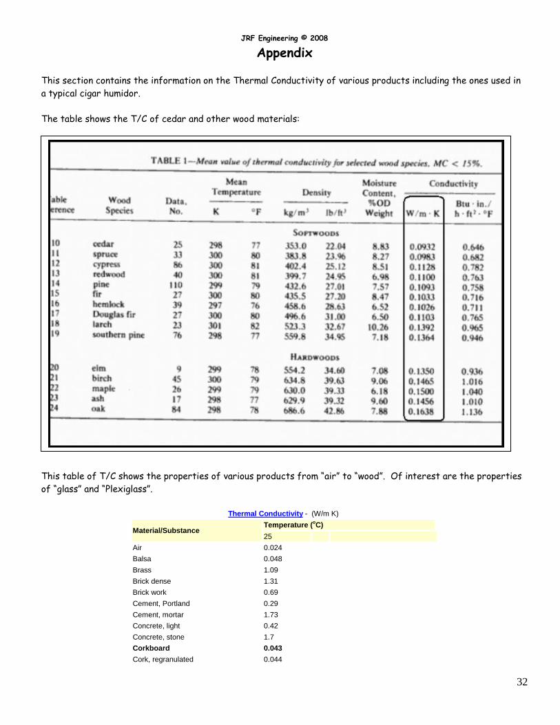
This section contains the information on the Thermal Conductivity of various products including the ones used in
a typical cigar humidor.
The table shows the T/C of cedar and other wood materials:
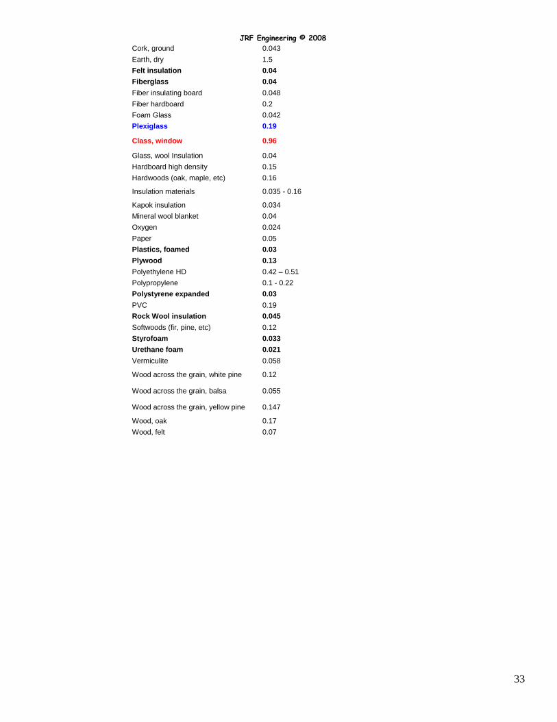
This table of T/C shows the properties of various products from “air” to “wood”. Of interest are the properties
of “glass” and “Plexiglass”.
Thermal Conductivity - (W/m K)
Material/Substance Temperature (
oC)
25
Air 0.024
Balsa 0.048
Brass 1.09
Brick dense 1.31
Brick work 0.69
Cement, Portland 0.29
Cement, mortar 1.73
Concrete, light 0.42
Concrete, stone 1.7
Corkboard 0.043
Cork, regranulated 0.044
JRF Engineering © 2008
33
Cork, ground 0.043
Earth, dry 1.5
Felt insulation 0.04
Fiberglass 0.04
Fiber insulating board 0.048
Fiber hardboard 0.2
Foam Glass 0.042
Plexiglass 0.19
Class, window 0.96
Glass, wool Insulation 0.04
Hardboard high density 0.15
Hardwoods (oak, maple, etc) 0.16
Insulation materials 0.035 - 0.16
Kapok insulation 0.034
Mineral wool blanket 0.04
Oxygen 0.024
Paper 0.05
Plastics, foamed 0.03
Plywood 0.13
Polyethylene HD 0.42 – 0.51
Polypropylene 0.1 - 0.22
Polystyrene expanded 0.03
PVC 0.19
Rock Wool insulation 0.045
Softwoods (fir, pine, etc) 0.12
Styrofoam 0.033
Urethane foam 0.021
Vermiculite 0.058
Wood across the grain, white pine 0.12
Wood across the grain, balsa 0.055
Wood across the grain, yellow pine 0.147
Wood, oak 0.17
Wood, felt 0.07