Embed Size (px)
Citation preview
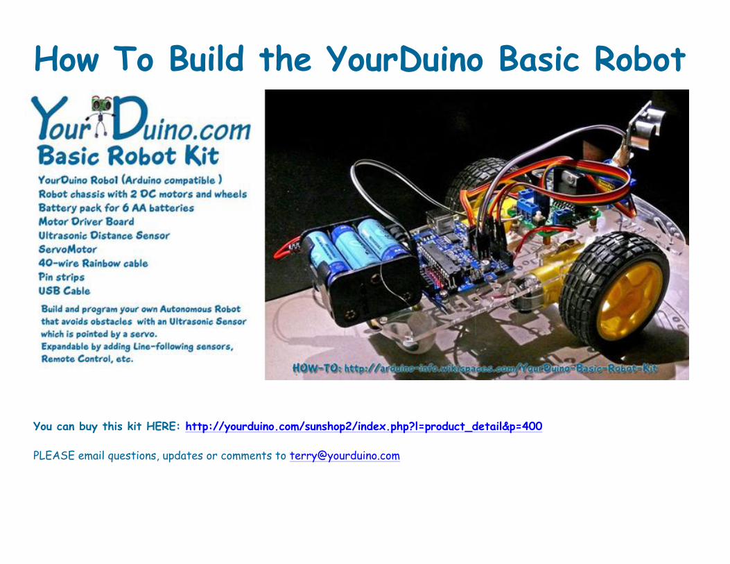
How To Build the YourDuino Basic Robot
You can buy this kit HERE: http://yourduino.com/sunshop2/index.php?l=product_detail&p=400
PLEASE email questions, updates or comments to [email protected]

This work is licensed under Creative Commons Attribution-ShareAlike 3.0 Unported License. You are free:
• to Share — to copy, distribute and transmit the work • to Remix — to adapt the work • to make commercial use of the work
Under the following conditions:
• Attribution — You must attribute the work in the manner specified by the author or licensor (but not in any way that suggests that they endorse you or your use of the work).
• Share Alike — If you alter, transform, or build upon this work, you may distribute the resulting work only under the same or similar license to this one.
• With the understanding that: • Waiver — Any of the above conditions can be waived if you get permission from the copyright holder. • Public Domain — Where the work or any of its elements is in the public domain under applicable law, that status is in no
way affected by the license. • Other Rights — In no way are any of the following rights affected by the license: Your fair dealing or fair use rights, or
other applicable copyright exceptions and limitations; The author's moral rights; Rights other persons may have either in the work itself or in how the work is used, such as publicity or privacy rights.
• Notice — For any reuse or distribution, you must make clear to others the license terms of this work. The best way to do this is with a link to this web page.
http://creativecommons.org/licenses/by-sa/3.0/ This work is licensed under Creative Commons Attribution-ShareAlike 3.0 Unported License
We have done much research and discussion with suppliers to bring in a kit with this many parts and capabilities at the $40 price. Here are the components of the kit:
• YourDuino Robo1 (Arduino compatible Microcomputer: Robot Brain) • Robot chassis with 2 DC motors and wheels • Battery pack for 6 AA batteries (Suggest rechargeable) • Motor Driver Board (Controls motors speed and direction) • Ultrasonic distance sensor (Looks for things in the way) • ServoMotor (Points the Distance Sensor in different directions) • 40-wire Rainbow cable (Connect the parts) • Pin strips (Connect the parts) • USB Cable (For uploading software to the YourDuino Robo1)
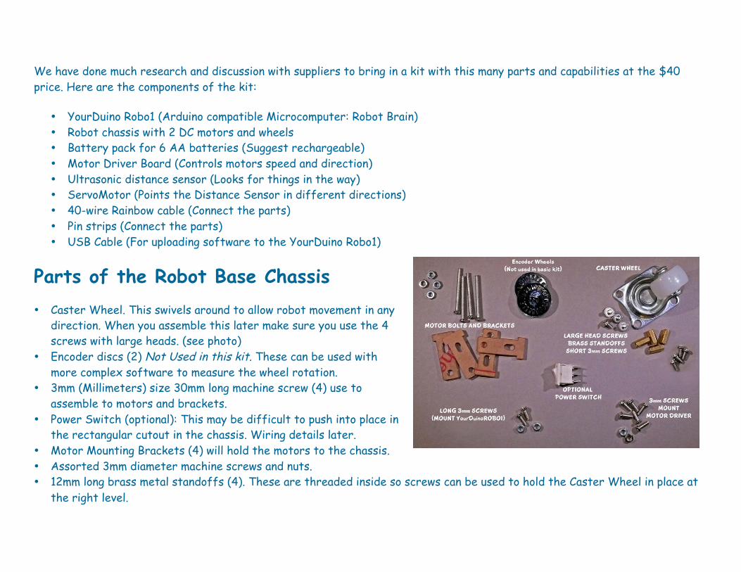
Parts of the Robot Base Chassis • Caster Wheel. This swivels around to allow robot movement in any
direction. When you assemble this later make sure you use the 4 screws with large heads. (see photo)
• Encoder discs (2) Not Used in this kit. These can be used with more complex software to measure the wheel rotation.
• 3mm (Millimeters) size 30mm long machine screw (4) use to assemble to motors and brackets.
• Power Switch (optional): This may be difficult to push into place in the rectangular cutout in the chassis. Wiring details later.
• Motor Mounting Brackets (4) will hold the motors to the chassis. • Assorted 3mm diameter machine screws and nuts. • 12mm long brass metal standoffs (4). These are threaded inside so screws can be used to hold the Caster Wheel in place at
the right level.

ROBOT CHASSIS AND WHEELS 1. Robot chassis: Laser-cut clear plastic. NOTE: This has a stick-on paper covering, and this is a good
time to remove it if you want the clear plastic to be shown. 2. Wheels (2). NOTE: The wheels have a hole with two flat sections. Make sure you line this up with
the motor shafts later when you attach them. 3. DC Gear Reduction Motor (2). Note these have 2 wires attached. Later when you assemble them to
the chassis, make sure the wires go toward the center of the robot.
Assembling the Robot Base Chassis and Attaching the Parts You will attach these parts to the robot chassis and then connect them electrically:
• Motor Driver Board • Yourduino Robo1 • Drive Motors • Ultrasonic Distance Sensor • ServoMotor • Battery Case
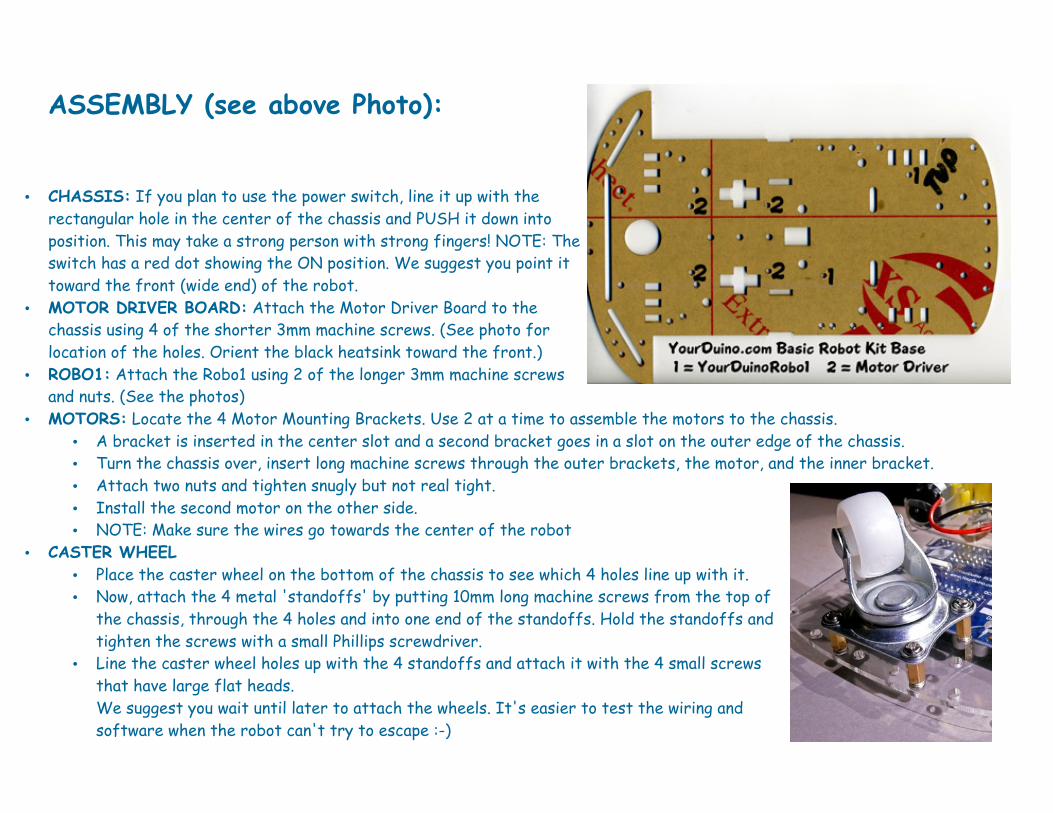
ASSEMBLY (see above Photo):
• CHASSIS: If you plan to use the power switch, line it up with the rectangular hole in the center of the chassis and PUSH it down into position. This may take a strong person with strong fingers! NOTE: The switch has a red dot showing the ON position. We suggest you point it toward the front (wide end) of the robot.
• MOTOR DRIVER BOARD: Attach the Motor Driver Board to the chassis using 4 of the shorter 3mm machine screws. (See photo for location of the holes. Orient the black heatsink toward the front.)
• ROBO1: Attach the Robo1 using 2 of the longer 3mm machine screws and nuts. (See the photos)
• MOTORS: Locate the 4 Motor Mounting Brackets. Use 2 at a time to assemble the motors to the chassis. • A bracket is inserted in the center slot and a second bracket goes in a slot on the outer edge of the chassis. • Turn the chassis over, insert long machine screws through the outer brackets, the motor, and the inner bracket. • Attach two nuts and tighten snugly but not real tight. • Install the second motor on the other side. • NOTE: Make sure the wires go towards the center of the robot
• CASTER WHEEL • Place the caster wheel on the bottom of the chassis to see which 4 holes line up with it. • Now, attach the 4 metal 'standoffs' by putting 10mm long machine screws from the top of
the chassis, through the 4 holes and into one end of the standoffs. Hold the standoffs and tighten the screws with a small Phillips screwdriver.
• Line the caster wheel holes up with the 4 standoffs and attach it with the 4 small screws that have large flat heads. We suggest you wait until later to attach the wheels. It's easier to test the wiring and software when the robot can't try to escape :-)
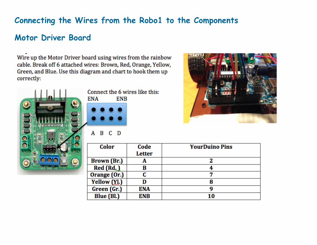
Connecting the Wires from the Robo1 to the Components
Motor Driver Board

Important note: There are two jumper blocks on the motor driver connected to the ENA and ENB Pins which must be removed. (The yellow arrows in the photo on the right point to the jumper blocks to remove.) You can pull them straight up off the pins using tweezers or your fingernails.
MOTOR DRIVER WIRING
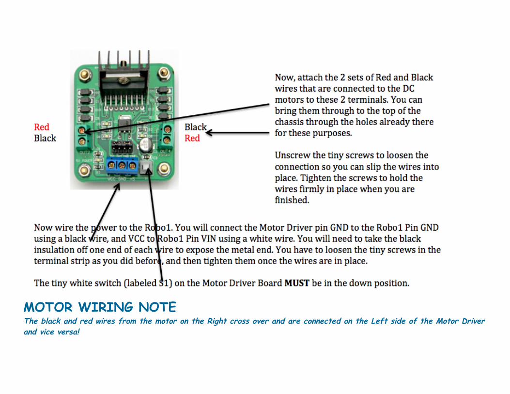
MOTOR WIRING NOTE The black and red wires from the motor on the Right cross over and are connected on the Left side of the Motor Driver and vice versa!
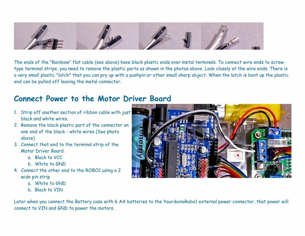
The ends of the "Rainbow" flat cable (see above) have black plastic ends over metal terminals. To connect wire ends to screw-type terminal strips, you need to remove the plastic parts as shown in the photos above. Look closely at the wire ends. There is a very small plastic "latch" that you can pry up with a pushpin or other small sharp object. When the latch is bent up the plastic end can be pulled off leaving the metal connector.
Connect Power to the Motor Driver Board 1. Strip off another section of ribbon cable with just
black and white wires. 2. Remove the black plastic part of the connector on
one end of the black - white wires (See photo above)
3. Connect that end to the terminal strip of the Motor Driver Board.
a. Black to VCC b. White to GND
4. Connect the other end to the ROBO1 using a 2 wide pin strip
a. White to GND b. Black to VIN
Later when you connect the Battery case with 6 AA batteries to the YourduinoRobo1 external power connector, that power will connect to VIN and GND to power the motors.
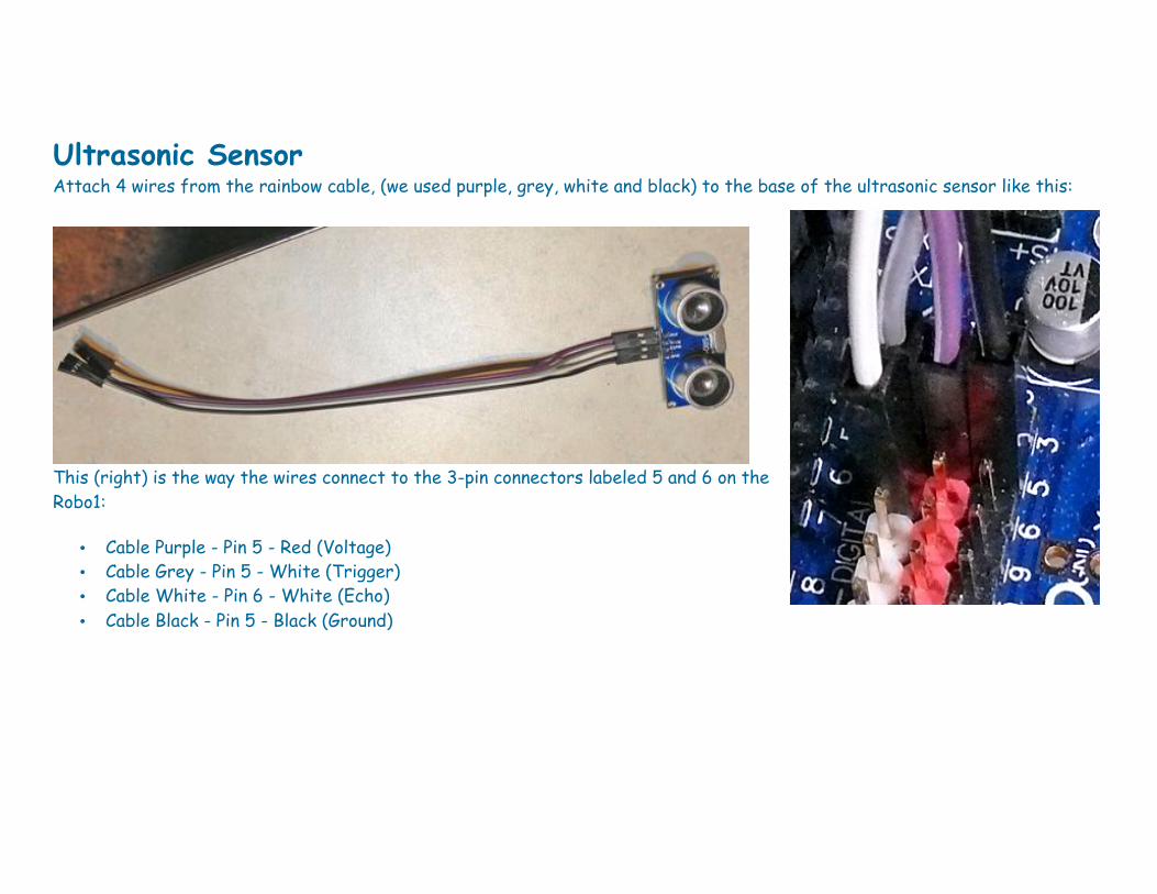
Ultrasonic Sensor Attach 4 wires from the rainbow cable, (we used purple, grey, white and black) to the base of the ultrasonic sensor like this:
This (right) is the way the wires connect to the 3-pin connectors labeled 5 and 6 on the Robo1:
• Cable Purple - Pin 5 - Red (Voltage) • Cable Grey - Pin 5 - White (Trigger) • Cable White - Pin 6 - White (Echo) • Cable Black - Pin 5 - Black (Ground)
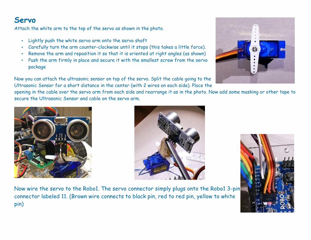
Servo Attach the white arm to the top of the servo as shown in the photo.
• Lightly push the white servo arm onto the servo shaft • Carefully turn the arm counter-clockwise until it stops (this takes a little force). • Remove the arm and reposition it so that it is oriented at right angles (as shown) • Push the arm firmly in place and secure it with the smallest screw from the servo
package
Now you can attach the ultrasonic sensor on top of the servo. Split the cable going to the Ultrasonic Sensor for a short distance in the center (with 2 wires on each side). Place the opening in the cable over the servo arm from each side and rearrange it as in the photo. Now add some masking or other tape to secure the Ultrasonic Sensor and cable on the servo arm.
Now wire the servo to the Robo1. The servo connector simply plugs onto the Robo1 3-pin connector labeled 11. (Brown wire connects to black pin, red to red pin, yellow to white pin)

Wheels Carefully push the wheels onto the motor axles. Hold the motor securely with one hand as you push the wheel in place. Here's the way your complete robot will look!
Arduino and Robot Software: Now we are going to program the ROBO1 to test some different parts of the robot and then install the more complex software which uses all the parts to run the robot around and avoid obstacles. First you need to have the Arduino "IDE" software development system installed on your computer and working. We have a detailed page on doing this if you have not used Arduino before. HERE: http://arduino-info.wikispaces.com/GettingStarted-Software You should have the Arduino IDE installed, the YourDuino ROBO1 on your robot connected to your computer with the USB cable, and the "Blink" Program successfully uploaded and run.
Uploading Test and Collision Avoidance software The Arduino software for this kit is on a separate page. HERE: http://arduino-info.wikispaces.com/YourDuino-Basic-Robot-Kit-Software You can buy this kit HERE: http://yourduino.com/sunshop2/index.php?l=product_detail&p=400 PLEASE email questions, updates or comments to [email protected]