Embed Size (px)
Citation preview
How-To #8 Work with Smart LEDs | 263
HT
This How-To shows how to connect and control a number of special light-emitting diodes, each of which can be set to any color and brightness. We will use NeoPixels from AdaFruit and control them with the Arduino™ library AdaFruit provides.
BackgroundWe love LEDs. But most of them light in only one color. True, so-called bicolor LEDs light one color when connected one way and a second color when the connection is reversed. But what we really want is an LED that can light up in any color and can be generated by mixing red, green, and blue light.
Tricolor LEDs that will do this are available. But to drive one of these LEDs requires three separate digital Arduino™ pins, one for each color. And that's for each LED. Want five in a row? Get ready to find 15 digital pins. This is just not practical.
Adafruit offers LEDs it refers to as NeoPixels that meet our requirements perfectly. These LEDs come in several forms, from small discs that can be sewn into clothing to strips and even indi-vidual NeoPixels that look a lot like ordinary LEDs with a few too many wires. These devices are perfect for us because each NeoPixel mixes the light from three LEDs—one green, one blue, and one red. Even better, each NeoPixel comes with its own tiny built-in microprocessor that lets it be controlled with just one wire.
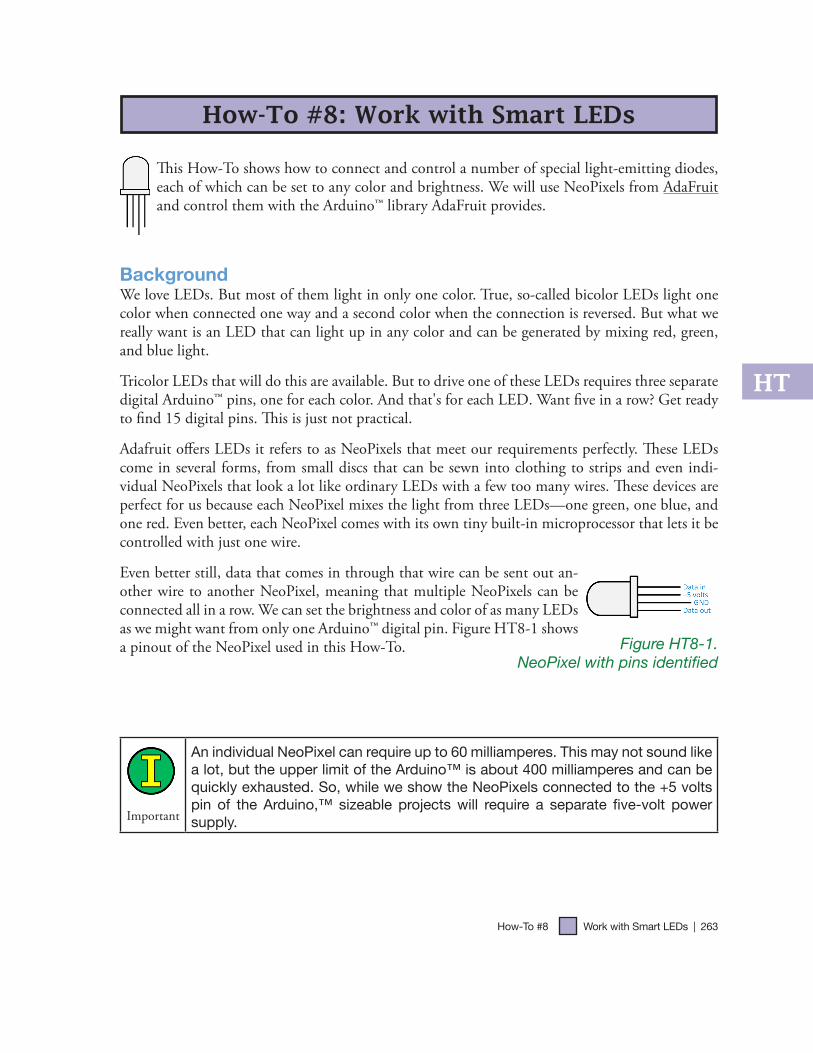
Even better still, data that comes in through that wire can be sent out an-other wire to another NeoPixel, meaning that multiple NeoPixels can be connected all in a row. We can set the brightness and color of as many LEDs as we might want from only one Arduino™ digital pin. Figure HT8-1 shows a pinout of the NeoPixel used in this How-To.
Figure HT8-1. NeoPixel with pins identified
Important
An individual NeoPixel can require up to 60 milliamperes. This may not sound like a lot, but the upper limit of the Arduino™ is about 400 milliamperes and can be quickly exhausted. So, while we show the NeoPixels connected to the +5 volts pin of the Arduino,™ sizeable projects will require a separate five-volt power supply.
How-To #8: Work with Smart LEDs
264 | Learn to Program in ArduinoTM C: 18 Lessons, from setup() to robots
Procedure:This How-To shows how to connect five NeoPixels together and, using the Adafruit library, drive them. It also reviews the methods the library makes available for the programmer and concludes with a modest sample sketch.
Materials:Quan-
tity Part Image Notes CatalogNumber
1 Arduino™ Uno
Single-board computer. This board is delicate and should be handled with care. When you are not using it, keep it in a box or plastic bag.
3102
1 USB Cable
This is a standard USB adapter cable with a flat connector on one end and a square connector on the other.
2301
1 Solderlessbread-board
Solderless bread-boards are reusable. 3108
5
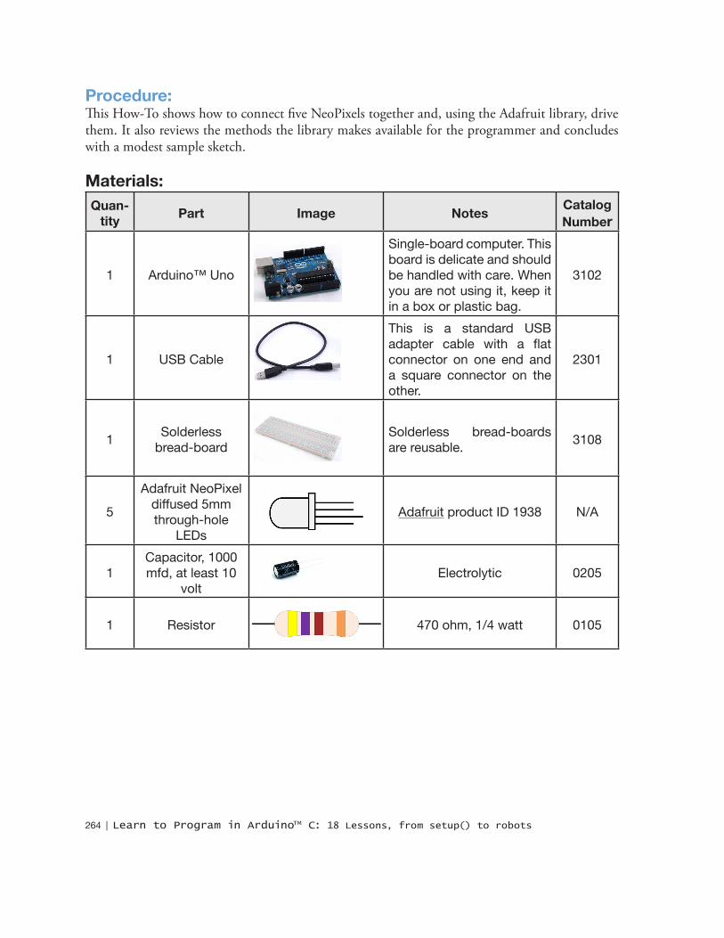
Adafruit NeoPixel diffused 5mm through-hole
LEDs
Adafruit product ID 1938 N/A
1Capacitor, 1000 mfd, at least 10
voltElectrolytic 0205
1 Resistor 470 ohm, 1/4 watt 0105

How-To #8 Work with Smart LEDs | 265
HT
Steps1. Assemble the parts shown in the Materials table.
2. Wire the parts as shown in Figure HT8-2.
Figure HT8-2. Schematic and pictorial of wiring for NeoPixel and Arduino™
3. Connect the Arduino™ to the programming computer via a USB cable.
Important
Be certain the flat side of each NeoPixel is oriented the same as in Figure HT8-2, and make sure that the positive and negative leads of the capacitor are not reversed.
Also notice the data-in pin of each LED is in the same row as the data-out pin of the preceding LED, except for the first, which is connected via a 470 ohm resistor to pin 6 of the Arduino.™
4. Download and install the Adafruit NeoPixel library, which can be found at https://github.com/adafruit/Adafruit_NeoPixel. Install the library by:
a. Placing the zip file in your Arduino™\libraries folder.
b. Unzipping the file in place. A new folder will be created.
c. Renaming the new folder Adafruit_NeoPixel.
d. Closing any open Arduino™ windows then restarting Arduino.™
266 | Learn to Program in ArduinoTM C: 18 Lessons, from setup() to robots
5. Open the strandtest sketch that comes with the library. It may be found under the File menu:
File -> Examples -> Adafruit_NeoPixel -> strandtest
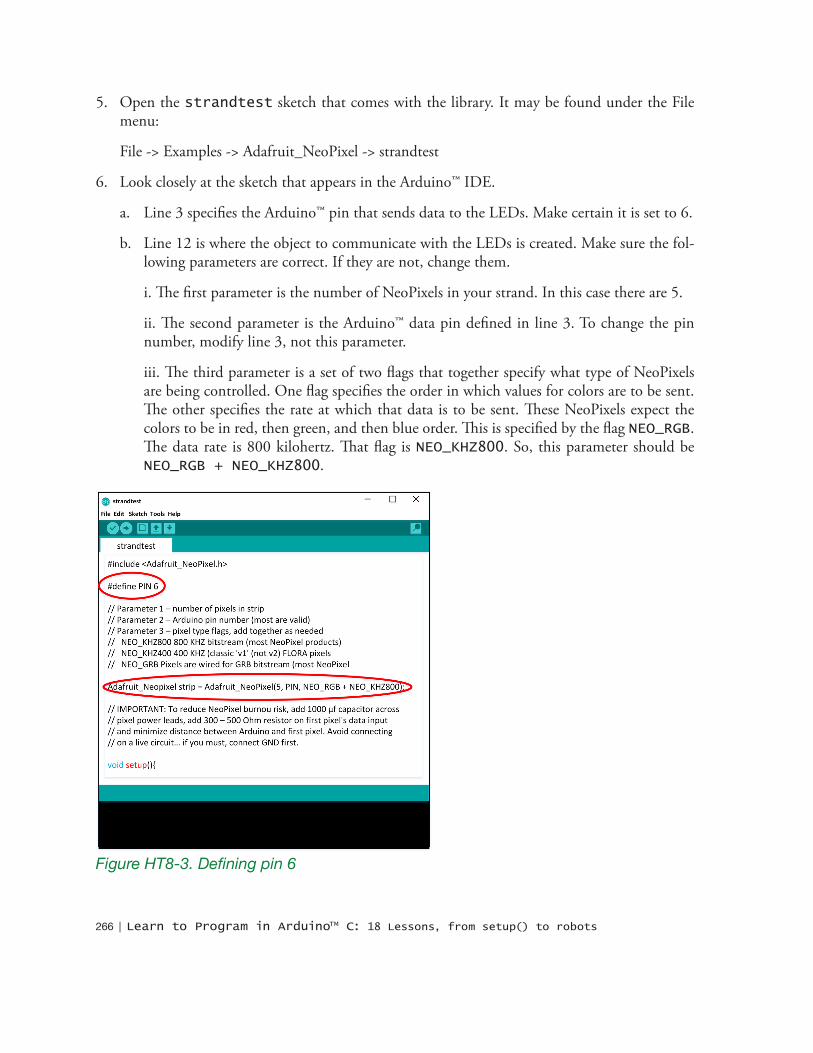
6. Look closely at the sketch that appears in the Arduino™ IDE.
a. Line 3 specifies the Arduino™ pin that sends data to the LEDs. Make certain it is set to 6.
b. Line 12 is where the object to communicate with the LEDs is created. Make sure the fol-lowing parameters are correct. If they are not, change them.
i. The first parameter is the number of NeoPixels in your strand. In this case there are 5.
ii. The second parameter is the Arduino™ data pin defined in line 3. To change the pin number, modify line 3, not this parameter.
iii. The third parameter is a set of two flags that together specify what type of NeoPixels are being controlled. One flag specifies the order in which values for colors are to be sent. The other specifies the rate at which that data is to be sent. These NeoPixels expect the colors to be in red, then green, and then blue order. This is specified by the flag NEO_RGB. The data rate is 800 kilohertz. That flag is NEO_KHZ800. So, this parameter should be NEO_RGB + NEO_KHZ800.
Figure HT8-3. Defining pin 6
How-To #8 Work with Smart LEDs | 267
HT
7. Upload strandtest to your Arduino.™ The NeoPixels should provide a rather entertaining display. All five LEDs should light, flash, and change color.
Writing your own sketchesThe strandtest is fun, but the real reason for the NeoPixel library is to provide programming tools for making your own color patterns. To this end, the AdaFruit library provides the following methods:
ConstructorUse this method to create an object to communicate with your string of NeoPixels:
Adafruit_NeoPixel(unsigned int numberOfNeoPixels, byte pinNumber, byte flags)where
numberOfNeoPixels is the number of NeoPixels to be controlled
pinNumber is the Arduino™ pin connected to the first NeoPixel in the string
flags specifies the color order and communication data rate. These are dependent on the type of NeoPixel being used. These are defined as:
NEO_GRB = green then blue then red
NEO_RGB = red then green then blue
NEO_KHZ400 = 400 kilohertz
NEO_KHZ800 = 800 kilohertz
Example HT8-1.Adafruit_NeoPixel myPixels = Adafruit_NeoPixel( 5, 6, NEO_RGB + NEO_KHZ800);
Other methodsUpdate the entire string of NeoPixels to the values set in the sketch. No color or brightness settings appear on any NeoPixels until this method is called.
void show()
Example HT8-2. myPixels.show();
Initialize communication with the NeoPixels. This method typically is called from the Arduino™ setup() method.
void begin()
268 | Learn to Program in ArduinoTM C: 18 Lessons, from setup() to robots
Example HT8-3. myPixels.begin();
Set the Arduino™ output pin. This step is not typically needed unless a pin different from that specified in the constructor is desired.
setPin(byte pin)
where
pin is the Arduino™ pin to be used to communicate with the NeoPixels
Example HT8-4. myPixels.setPin(4); // set output pin to 4
Set the color of a specific NeoPixel by specifying the amounts of red, green, and blue.
void setPixelColor(unsigned int pixelNumber, byte red, byte green, byte blue)
where
pixelNumber is which NeoPixel is to be set. Keep in mind that the number of the first pixel is zero, the second is one, the third is two, and so on until the last, which is the number of NeoPixels in the string minus 1.
red is a number from 0 through 255 that specifies the amount of red in the final color.
green is a number from 0 through 255 that specifies the amount of green in the final color.
blue is a number from 0 through 255 that specifies the amount of blue in the final color.
Example HT8-5. // set 3rd NeoPixel to yellow myPixels.setPixelColor( 2, 255, 255, 0); myPixels.show();
Set the color of a specific NeoPixel with a "packed" 32-bit unsigned integer
setPixelColor(unsigned int pixelNumber, unsigned longcolor)
How-To #8 Work with Smart LEDs | 269
HT
where
pixelNumber is which NeoPixel is to be set. Keep in mind that the number of the first pixel is zero, the second is one, the third is two, and so on until the last, which is the number of NeoPixels in the string minus 1.
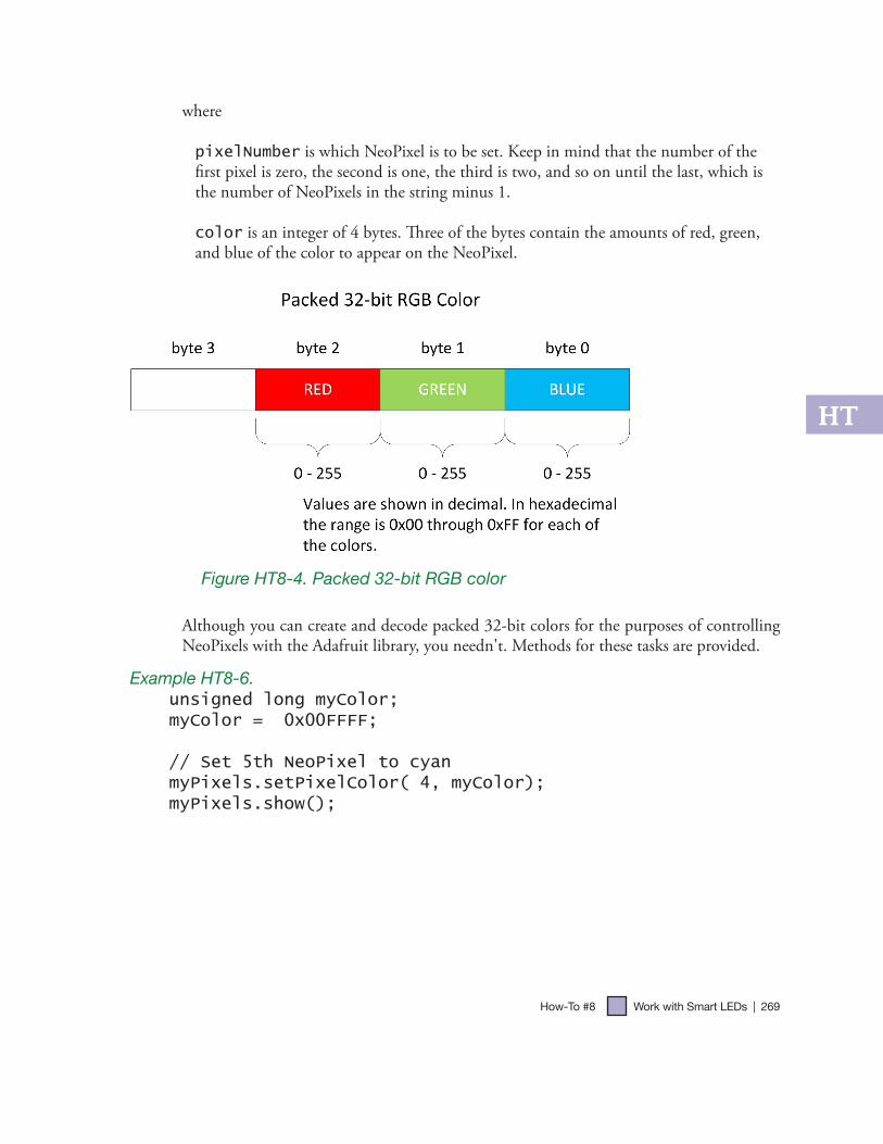
color is an integer of 4 bytes. Three of the bytes contain the amounts of red, green, and blue of the color to appear on the NeoPixel.
Figure HT8-4. Packed 32-bit RGB color
Although you can create and decode packed 32-bit colors for the purposes of controlling NeoPixels with the Adafruit library, you needn't. Methods for these tasks are provided.
Example HT8-6.unsigned long myColor;myColor = 0x00FFFF;
// Set 5th NeoPixel to cyan myPixels.setPixelColor( 4, myColor);myPixels.show();
270 | Learn to Program in ArduinoTM C: 18 Lessons, from setup() to robots
Convert separate red, green, and blue colors into a packed 32-bit RGB color.
unsigned long Color( byte red, byte green, byte blue);
where
packedColor is an integer of 4 bytes. Three of the bytes contain the amounts of red, green, and blue of the color to appear on the NeoPixel.
red a number from 0 through 255 that specifies the amount of red in the final color.
green a number from 0 through 255 that specifies the amount of green in the final color.
blue a number from 0 through 255 that specifies the amount of blue in the final color.
returns an unsigned long integer containing the amounts of red, green, and blue encoded in the packed 32-bit color format.
Example HT8-7.unsigned long myPackedColor;
// color values for magentabyte red = 255;byte green = 0;byte blue = 255;
myPackedColor = myPixels.Color(red, green, blue);
Get the color of a particular NeoPixel
unsigned getPixelColor(byte whichNeoPixel)
where
whichNeoPixel is which NeoPixel is to be read. Keep in mind that the number of the first pixel is zero, the second is one, the third is two, and so on until the last, which is the number of NeoPixels in the string minus 1.
returns an unsigned integer containing the amounts of red, green, and blue in the color of whichNeoPixel.
How-To #8 Work with Smart LEDs | 271
HT
Example HT8-8.unsigned long myPackedColor;
// get color of 4th NeoPixelmyPackedColor = myPixels.getPixelColor(3);
Get an array of all the NeoPixel color values in NeoPixel order
byte* myPixels.getPixels();
where
myPixelArray holds the address in memory of an array of data for each NeoPixel. The use of this method is not discussed in this note.
Get the number of NeoPixels being controlled.
unsigned int numPixels();
Example HT8-9.unsigned int number = myPixels.numPixels();
Set overall brightness
void setBrightness( byte level)
where
level is a positive integer from 0 through 255 that specifies overall brightness for the string of NeoPixels. 0 is off; 255 is maximum brightness.
Example HT8-10.myPixels.setBrightness(127); // Half brightnessmyPixels.show();
272 | Learn to Program in ArduinoTM C: 18 Lessons, from setup() to robots
Putting it all together
To use the library for your own sketch, follow these steps:
1. In the Arduino™ IDE create a new sketch.
2. At the top of the sketch file include the library sketch header file with the statement:
#include <Adafruit_NeoPixel.h>
3. Before writing any methods, create a NeoPixel object. This example assumes five NeoPixels with data coming from pin 6.
Adafruit_NeoPixel myStrip = Adafruit_NeoPixel(5,6, NEO_RGB + NEO_KHZ800);
4. Initialize the string of NeoPixels inside the setup() method.
myStrip.begin();
5. Use the NeoPixel methods as needed in the rest of the sketch. Remember, in this example each begins with myStrip.