Embed Size (px)
Citation preview
Host Integration Tools
Installation and User Guide
Version 3.4

Copyright 2010 Dell, Inc. All rights reserved.
EqualLogic is a registered trademark of Dell, Inc.
Dell is a trademark of Dell, Inc.
All trademarks and registered trademarks mentioned herein are the property of their respective owners.
Information in this document is subject to change without notice.
Reproduction in any manner whatsoever without written permission is strictly forbidden.
July 2010
Part Number: 110-6037-EN-R1

1–iii
Table of Contents
Preface ..................................................................................................................................................... viiAudience ................................................................................................................................................................... viiOrganization ............................................................................................................................................................. viiConventions .............................................................................................................................................................viiiOverview of EqualLogic Products............................................................................................................................. ixRelated Documentation .............................................................................................................................................. xTechnical Support and Customer Service................................................................................................................... xOnline Services.......................................................................................................................................................... xi
1 Installation........................................................................................................................................... 1-1Host Integration Tools Components........................................................................................................................1-1Supported Applications ...........................................................................................................................................1-2
Microsoft Exchange Server...............................................................................................................................1-2Microsoft SQL Server.......................................................................................................................................1-3Microsoft Hyper-V............................................................................................................................................1-4
Installing Host Integration Tools on a Microsoft Failover Cluster..........................................................................1-4Considerations when Configuring Failover Clusters...............................................................................................1-4Joining a Computer into a Windows Failover Cluster.............................................................................................1-5
ASM/ME Cluster Administrative Account.......................................................................................................1-5Changing the EqlReqService Logon Account ..................................................................................................1-6
PS Series Group Network Recommendations .........................................................................................................1-6Installing the Host Integration Tools .......................................................................................................................1-7
Installation Considerations................................................................................................................................1-7Windows Server 2008 Installation Considerations...........................................................................................1-8Windows Server 2008 Core Additional Considerations ...................................................................................1-8Preparing to Install ............................................................................................................................................1-9First Time Installation Summary ......................................................................................................................1-9Updating, Maintaining, and Removing an Installation ...................................................................................1-11Performing an Unattended Installation ...........................................................................................................1-11
2 Remote Setup Wizard......................................................................................................................... 2-1Remote Setup Wizard Overview .............................................................................................................................2-1
Remote Setup Wizard Computer and Group Requirements .............................................................................2-1Using the Remote Setup Wizard to Configure Groups ...........................................................................................2-2
Launching the Remote Setup Wizard ...............................................................................................................2-2Initializing an Array and Creating a Group ......................................................................................................2-2
Using Remote Setup Wizard to Identify a PS Series Array .......................................................................2-4PS Series Array Initialization Procedure ....................................................................................................2-5
Initializing an Array and Expanding a Group...................................................................................................2-7Enabling (or Modifying) Computer Access to a Group....................................................................................2-9Disabling Microsoft Service Access to a Group.............................................................................................2-11
3 Remote Setup Command Line Utility ............................................................................................... 3-1General Command Syntax for the RSWCLI ...........................................................................................................3-1Entering Commands ...............................................................................................................................................3-1Discovering a PS Series Array ................................................................................................................................3-2
Command Syntax..............................................................................................................................................3-2Initializing a PS Series Array ..................................................................................................................................3-2
Command Syntax..............................................................................................................................................3-2

Host Integration Tools Installation and User Guide Table of Contents
1–iv
Adding Access to the PS Series Array Group .........................................................................................................3-3Command Syntax..............................................................................................................................................3-4
Listing Accessible PS Array Groups .......................................................................................................................3-4Command Syntax..............................................................................................................................................3-5
Modifying Access to PS Series Array Group ..........................................................................................................3-5Command Syntax..............................................................................................................................................3-5
Removing Host Access to a PS Series Array Group ...............................................................................................3-6Command Syntax..............................................................................................................................................3-6
Listing or Modifying MPIO Settings.......................................................................................................................3-6Command Syntax..............................................................................................................................................3-6
Listing Included and Excluded Subnets for MPIO..................................................................................................3-7Command Syntax..............................................................................................................................................3-7
Including a Subnet for Use by MPIO ......................................................................................................................3-8Command Syntax..............................................................................................................................................3-8
Excluding a Subnet for User By MPIO ...................................................................................................................3-9Command Syntax..............................................................................................................................................3-9
4 Using the Multipath I/O DSM ........................................................................................................... 4-1Introduction to Multipath I/O DSM.........................................................................................................................4-1Prerequisites for Configuring Multipath I/O DSM..................................................................................................4-3Information Required to Configure Multipath I/O ..................................................................................................4-4Configuring Multipath I/O Between a Computer and a Group ...............................................................................4-4
Logging into a Volume with Multipath I/O ......................................................................................................4-5Logging Off a Volume with Multipath I/O.......................................................................................................4-5
Viewing MPIO Sessions..........................................................................................................................................4-6Setting the MPIO Load Balancing Policy ...............................................................................................................4-8
Procedure to display the connections to a target and optionally change its load balancing policy on operating systems other than Windows Server 2008 R2: ........................................................................................................4-8
Procedure to display the connections to a target and optionally change its load balancing policy on Windows Server 2008 R2: .......................................................................................................................................................4-8Excluding an IP Address from a Subnet..................................................................................................................4-9
5 Using the VDS Provider ..................................................................................................................... 5-1VDS Provider Requirements ...................................................................................................................................5-1VDS Provider Guidelines and Restrictions .............................................................................................................5-1Simple Target and LUN Naming.............................................................................................................................5-2Importing VSS Snapshots........................................................................................................................................5-2Modifying Access Controls .....................................................................................................................................5-3Creating a Volume Using Storage Manager for SANs............................................................................................5-3
Starting the Storage Manager for SANs ...........................................................................................................5-3
6 Using the EqualLogic HPC iSCSI Provider ..................................................................................... 6-1HPC iSCSI Provider Installation .............................................................................................................................6-1Configuring the PS Series Array .............................................................................................................................6-1Settings ....................................................................................................................................................................6-1
7 Tools and Utilities ............................................................................................................................... 7-1The EqlXcp Utility ..................................................................................................................................................7-1
EqlXcp Utility Restrictions...............................................................................................................................7-1Using the EqlXcp Utility...................................................................................................................................7-1
Debug Tracing and the EqlLog Utility ....................................................................................................................7-2

Host Integration Tools Installation and User Guide Table of Contents
1–v
Running the EqlLog utility ...............................................................................................................................7-2EqlLog Command Line Options .......................................................................................................................7-2Trace Log Daemon............................................................................................................................................7-3
Glossary .................................................................................................................................... Glossary-1
Index................................................................................................................................................ Index-1

Host Integration Tools Installation and User Guide Table of Contents
1–vi
Host Integration Tools Installation and User Guide
vii
Preface
The Host Integration Tools is a collection of applications and utilities that simplifies the configuration and administration of EqualLogic PS Series storage arrays on Microsoft® Windows® computers.
Audience
The information in this guide is intended for computer system administrators who are responsible for, and have appropriate knowledge of, the following tasks:
• Installing and using the Host Integration Tools.
• PS Series group administration.
• Windows and Windows Server operating environment administration.
• iSCSI initiator operation.
• Windows Exchange database and SQL Server database administration.
Organization
The organization of this guide is as follows:
• Chapter 1, Installation – Describes the Host Integration Tools kit components, operating system support, and how to install the tools.
• Chapter 2, Remote Setup Wizard – Describes how to use the Remote Setup Wizard to initialize arrays and create or expand groups, configure system access to a group, and configure multipath I/O between a system and group.
• Chapter 3, Remote Setup Command Line Utility – Describes how to use the Remote Setup Command Line Interface to manage PS Series arrays.
• Chapter 4, Using the Multipath I/O DSM – Describes how to use the EqualLogic Multipath I/O (MPIO) DSM (Device Specific Module) to manage redundant network paths to PS Series volumes for improved availability and performance.
• Chapter 5, Using the VDS Provider – Describes how to create volumes by using the VDS provider in conjunction with Microsoft VDS and Microsoft Storage Manager for SANS.
• Chapter 6, Using the EqualLogic HPC iSCSI Provider – Describes how to install and configure the HPC iSCSI Provider, which enables Microsoft HPC Server provisioning of iSCSI volumes.
• Chapter 7, Tools and Utilities – Describes the EqlXcp and EqlLog utilities, which are included with the Host Integration Toolkit.
• Glossary – Defines storage technology terminology that is specific to EqualLogic.

Host Integration Tools Installation and User Guide
viii
Conventions
Typographical conventions are shown in the following table.
Convention Usage
fixed width font Command, parameter, output, file name, link, button, field, URL address, or e-mail address.
bold fixed width Input to command prompt.
fixed_width_italics Indicates that you replace the variable with a command, parameter, file name, etc.
{text1 | text2} Indicates that you can choose one of the items presented.
parameter ... Trailing dots indicate that you can enter multiple parameters on a command line, separated by spaces.
option[,...] Trailing dots, preceded by a comma, indicate you can enter multiple variables, separated by commas and no spaces.
[parameter] Brackets indicate that the item inside the bracket is optional.
> A greater than symbol represents a Windows system prompt.
Host Integration Tools Installation and User Guide
ix
Overview of EqualLogic Products
Thank you for your interest in EqualLogic™ PS Series storage products. We hope you will find them intuitive and simple to configure and manage.
PS Series arrays optimize resources by automating performance and network load balancing. Additionally, PS Series arrays offer all-inclusive array management software, host software, and free firmware updates. The features and products described next are available at no additional cost.
PS Series Software
• Firmware - Installed on each array, PS Series firmware allows you to manage your storage environment and provides capabilities such as volume snapshots, cloning, and replication to ensure data hosted on the arrays is protected in the event of an error or disaster.
- Group Manager GUI: Provides a graphical user interface for managing a group.
- Group Manager CLI: Provides a command line interface for managing a group.
• Manual Transfer Utility (MTU) – Runs on Windows and Linux systems and enables you to use physical media to securely transfer large amounts of data to a replication partner, facilitating replication and preventing network congestion.
Host Software for Windows
• Host Integration Tools:
- Remote Setup Wizard (RSW): Initializes new PS Series arrays, configures host connections to PS Series groups, and configures and manages multipathing.
- Multipath I/O Device Specific Module (MPIO DSM): Includes a connection awareness-module that understands PS Series network load balancing and facilitates host connections to PS Series volumes.
- VSS and VDS Provider Services: Allows 3rd party backup software vendors to perform off-host backups.
- Auto-Snapshot Manager/Microsoft Edition (ASM/ME): ASM/ME is a VSS requesting application that uses PS Series snapshots, cloning, and replication to provide point-in-time protection of critical data for supported applications, including SQL Server, Exchange Server, Hyper-V, and NTFS file shares.
• SAN HeadQuarters (SANHQ): Provides centralized monitoring, historical performance trending, and event reporting for multiple PS Series groups.
Host Software for VMware
• Storage Adapter for Site Recovery Manager (SRM): Allows SRM to understand and recognize PS Series replication for full SRM integration.
• Auto-Snapshot Manager/VMware Edition (ASM/VE): Integrates with VMware Virtual Center and PS Series snapshots to allow administrators to enable Smart Copy protection of Virtual Center folders, datastores, and virtual machines.
Current Customers Please Note: You may not be running the latest versions of the tools and software listed above. If you are under a valid warranty or support agreement for your PS Series array, you are entitled to obtain the latest updates and new releases as they become available.

Host Integration Tools Installation and User Guide
x
Related Documentation
For detailed information about PS Series arrays, groups, volumes, array software, and host software, see the following documentation:
Technical Support and Customer Service
Dell's support service is available to answer your questions about PS Series SAN arrays. If you have an Express Service Code, have it ready when you call. The code helps Dell's automated-support telephone system direct your call more efficiently.
Contacting Dell
Dell provides several online and telephone-based support and service options. Availability varies by country and product, and some services might not be available in your area.
For customers in the United States, call 800-945-3355.
Note: If you do not have access to an Internet connection, contact information is printed on your invoice, packing slip, bill, or Dell product catalog.
Use the following procedure to contact Dell for sales, technical support, or customer service issues:
1. Visit support.dell.com or the Dell support URL specified in information provided with the Dell product.

Host Integration Tools Installation and User Guide
xi
2. Select your locale. Use the locale menu or click on the link that specifies your country or region.
3. Select the required service. Click the "Contact Us" link, or select the Dell support service from the list of services provided.
4. Choose your preferred method of contacting Dell support, such as e-mail or telephone.
Online Services
You can learn about Dell products and services using the following procedure:
1. Visit www.dell.com (or the URL specified in any Dell product information).
2. Use the locale menu or click on the link that specifies your country or region.


Host Integration Tools Installation and User Guide Installation
1–1
1 Installation
Host Integration Tools installation topics include the following:
• Host Integration Tools Components on page 1-1
• Supported Applications on page 1-2
• Joining a Computer into a Windows Failover Cluster on page 1-5
• Installing the Host Integration Tools on page 1-7
Before you begin any installation procedures:
• Check the Dell Technical Support Web site to make sure you have the latest Host Integration Tools kit and documentation.
• Read the current revision of the Release Notes for the most recent information about:
– Supported and required software and firmware releases.
– Supported operating system versions.
– The latest information about Host Integration Tools known issues and usage constraints.
On a single computer, you must log in to Windows as administrator or be a member of the administrators group to install and use the Host Integration Tools. When installing on a cluster, you must run the installation from an account that is a member of the domain administrators group.
Note: If a previous version of a component is already installed on your computer, the installation program updates it to the latest version.
Host Integration Tools Components
The Host Integration Tools installation program enables you to choose which components to install on your computer. The components are listed in Table 1-1.
Table 1-1: Host Integration Tools Components
Component Description
Remote Setup Wizard Enables you to initialize a PS Series SAN array and set up or expand a PS Series group. You can also configure multipathI/O. See Chapter 2, Remote Setup Wizard.
Remote Setup Wizard Command Line Utility (RSWCLI)
Provides an alternative to using the Remote Setup Wizard, with set up commands that you can execute at the Windows command prompt instead of using the GUI. The RSWCLI is described in Chapter 3, Remote Setup Command Line Utility.
Dell Auto-Snapshot Manager/Microsoft Edition (ASM/ME)
A Microsoft Management Console (MMC) snap-in tool that enables you to create and manage Smart Copies (snapshots, clones, and replicas). An alternate command-line interface facilitates custom operations and scripting. See the Auto-Snapshot Manager/Microsoft Edition User’s Guide
EqualLogic VSS Provider Supports VSS management of application-consistent Smart Copies.

Host Integration Tools Installation and User Guide Installation
1–2
Supported Applications
The applications described here are supported for use with Host Integration Tools, subject to any issues and constraints specified in the Release Notes.
Microsoft Exchange Server
Host Integration Tools supports online backup and quick restore of Exchange components by using the ASM/ME GUI.
The installer verifies that a supported version of Microsoft Exchange Server exists on the target installation computer. If the installed version is not supported, you have the following options:
• Cancel the ASM/ME installation and update Microsoft Exchange Server.
• Proceed with the ASM/ME installation. In this case, ASM/ME operations that are specific to Microsoft Exchange Server will not function until you have updated to a supported version.
Note: If ASM/ME detects an unsupported version of Microsoft Exchange Server, a red arrow appears next to the application in the ASM/ME console tree.
Supported features for Microsoft Exchange Server include:
• Creating snapshot, replica, and clone Smart Copies of Microsoft Exchange Server mailbox databases (for Exchange 2010) or storage groups (for Exchange 2007 and 2003) residing on PS Series volumes.
• Automatic discovery of the Microsoft Exchange Server instance and its components.
• Consistent, online backup and quick restore of Microsoft Exchange mailbox databases (for Exchange 2010) or storage groups (for Exchange 2007 and 2003) residing on PS Series volumes
The following types of Microsoft Exchange Server application behaviors are supported for Smart Copies:
EqualLogic VDS Provider Enables you to use Microsoft VDS and Microsoft Storage Manager for SANs to create and manage volumes in a PS Series group. See Chapter 5, Using the VDS Provider.
EqualLogic Multipath I/O DSM (MPIO DSM)
A driver module that works in conjunction with the Microsoft MPIO driver to support multipathing. This feature dynamically balances your iSCSI SAN traffic load over multiple network paths between the computer and the PS Series group. You need multiple iSCSI host bus adapters to use this feature. Configure EqualLogic Multipath I/O DSM by using the Remote Setup Wizard, as described in Chapter 2, Remote Setup Wizard. As an alternative to the Remote Setup Wizard, you can use the RSWCLI, described in Chapter 3, Remote Setup Command Line Utility.
Microsoft iSCSI Initiator Enables connections to iSCSI targets. Required by Remote Setup Wizard, ASM/ME, and the VDS provider. For information about using the initiator, see the Microsoft documentation. See Installation Considerations on page 1-7.
iSCSI Initiator properties tab Provides information about the status and history of the multipath connections supported by the Multipath I/O DSM.
Java Runtime Environment Enables you to use the EqualLogic Java-based graphical user interfaces (GUIs).
Table 1-1: Host Integration Tools Components (Continued)
Component Description
Host Integration Tools Installation and User Guide Installation
1–3
• Copy backup type (on Microsoft Exchange Server 2010, 2007 and 2003 sp2).
• Scheduling Smart Copy creation for Microsoft Exchange mailbox databases (for Exchange 2010) or storage groups (for Exchange 2007 and 2003).
• Recovery Mailbox Database creation for Microsoft Exchange 2010 item level restores.
• Automated Recovery Storage Group setup for Microsoft Exchange 2007 item level restores.
• Recovery Storage Group creation setup for Microsoft Exchange 2003 item level restores.
• The Clone and Restore All as New option is available for Microsoft Exchange 2010 and 2007 Smart Copies. The Clone and Restore All as New feature allows you to clone a mailbox database from a source Exchange server, and then set it up as a new mailbox database on a target Exchange server.
• The option to perform checksum verification (database and transaction log) and optional soft recovery immediately after Smart Copy creation. You can also use this feature by setting up a global verification task on the Exchange Server host or a remote host.
See the ASM/ME User Guide for more information.
Microsoft SQL Server
Host Integration Tools supports online backup and quick restore of Microsoft SQL Server databases using the Auto-Snapshot Manager/Microsoft Edition (ASM/ME) GUI.
Although it is not detected during installation, ASM/ME verifies the compatibility of the installed version of SQL Server. The ASM/ME Applications writer node is disabled if the installed version and service pack level of Microsoft SQL Server is unsupported. Supported Microsoft SQL Server versions with required service pack updates are described in the Release Notes.
Note: If ASM/ME detects an unsupported version of Microsoft SQL Server, a red arrow appears next to the application in the ASM/ME console tree.
Supported features for Microsoft SQL Server include:
• Support for creating snapshots, replicas, or clones of Microsoft SQL Server databases residing on PS Series volumes.
• Automatic discovery of Microsoft SQL Server instance and all SQL databases.
• Consistent, online backups and quick restores of Microsoft SQL Server databases residing on PS Series volumes.
Microsoft SQL Server application supports both full and copy backup type Smart Copies on Microsoft SQL Server 2005 and 2008.
The following Microsoft SQL Server database restore operations are supported:
• Restore All - Restores databases to the point-in-time represented by a Smart Copy. Optionally, you can apply transaction log backups to a database being restored.
• Restore named_databases - Selectively restores one or more databases sharing the same volume (uses an automated file copy operation after the Smart Copy is imported, if volume sharing is detected).
• Restore All as New - Restores all databases as new databases with new mount points.

Host Integration Tools Installation and User Guide Installation
1–4
• Clone and Restore as New - Recovers a database from a cloned replica Smart Copy on the secondary group. Optionally, you can mount a read-only copy of the replica Smart Copy for backup to tape or for data mining (volume replication stops while replica is mounted).
See the ASM/ME User Guide for more information.
Microsoft Hyper-V
Hyper-V enables you to run a client virtual machine (also called a guest O/S) in child partitions. ASM/ME enables you create application-consistent and crash-consistent Smart Copies of virtual machines, dependent on Guest O/S type. You can also:
• Define collections of virtual machines.
• Set up schedules for creating Smart Copies of virtual machines.
• Restore Smart Copies of virtual machines.
• Restore virtual hard drive (VHD) volumes.
See the ASM/ME User Guide for more information.
Installing Host Integration Tools on a Microsoft Failover Cluster
The following parallel installation requirements apply when you configure the Host Integration Tools on more than one node in the Microsoft Failover Cluster:
• You must install the same version of Host Integration Tools on every cluster node.
• You must select the same set of components (such as ASM/ME or VDS) on each node.
• You must run the Remote Setup Wizard on each node, specifying identical responses for each screen.
• If you are using multipathing with the EqualLogic MPIO DSM, you must use an identical configuration on each node.
Considerations when Configuring Failover Clusters
Information on configuring, using and troubleshooting Microsoft Failover Clusters can be found on Microsoft's TechNet website.
• Computers running Windows Server 2003 and using the cluster service might be unable to join a cluster after the computer is first restarted. See the Microsoft Knowledgebase article at:http://support.microsoft.com/kb/938615
• The cluster service might not start after you restrict the available IP Ports for remote procedure calls. See the Microsoft Knowledgebase article at:http://support.microsoft.com/kb/258469
• In a server cluster that uses only iSCSI technology for shared storage devices, you must make the cluster service dependent on the Microsoft iSCSI Initiator service. This makes the Microsoft iSCSI Initiator service

Host Integration Tools Installation and User Guide Installation
1–5
start before the cluster service. See the Microsoft Knowledgebase article at:http://support.microsoft.com/kb/883397
• When you start your Microsoft Windows Server 2003-based computer that is running Windows Clustering, an Event ID: 57 might be logged. See the Microsoft Knowledgebase article at:http://support.microsoft.com/default.aspx/kb/885688/en-us
See also the ASM/ME User’s Guide for information about configuring ASM/ME for use on Windows Failover Clusters and for information about cluster resource ownership.
Joining a Computer into a Windows Failover Cluster
The following considerations apply when you join a single computer running Host Integration Tools into a Microsoft Failover Cluster:
• If you are using continuous cluster replication (CCR) or a Database Availability Group (DAG) under Microsoft Exchange, you do not need to supply Host Integration Tools with cluster access information during the installation. You are prompted to check a box during the installation indicating that CCR or DAG is in use and subsequently you do not need to supply a user name or password.
• You must maintain parallel installations (see Installing Host Integration Tools on a Microsoft Failover Cluster on page 1-4)
• You must use an account with the correct credentials (see ASM/ME Cluster Administrative Account on page 1-5)
• You must change the logon account for the EQLReqService (see Changing the EqlReqService Logon Account on page 1-6)
Note: If you install Host Integration Tools on a running cluster, you are prompted to configure the installation for cluster operation and it is not necessary to complete the tasks described in the following sections.
ASM/ME Cluster Administrative Account
You perform many operations across cluster nodes. Therefore, you must log in using a user account that has the following characteristics:
• The account is a Microsoft domain user account
• The account has local administrative access
Consider creating a named account such as ASMadmin to use for ASM/ME operations on the cluster. You can use this account to log on to required services as described in Changing the EqlReqService Logon Account on page 1-6.
If any cluster node is running Microsoft Exchange and Microsoft SQL Server, (using PS Series iSCSI volumes) you must also make sure that your user account has the appropriate security group access for those applications.
Note: Certain operations may fail with an error message if you do not use an appropriate account.

Host Integration Tools Installation and User Guide Installation
1–6
Changing the EqlReqService Logon Account
To join a system running Host Integration Tools to a cluster, you must change the logon for the EQLReqService. Use the ASM/ME cluster administrative account referenced in ASM/ME Cluster Administrative Account on page 1-5.
1. Open the Windows Control Panel
2. Double-click Administrative Tools.
3. Double-click Services. The Services window appears.
4. Double-click EQLReqService.
5. Select the Log On tab and change the logon account to the ASM/ME administrative account, or any account with appropriate access credentials.
PS Series Group Network Recommendations
Table 1-2 describes the network recommendations for PS Series group operation and for computer access to group. All the normal networking rules apply; however, network configuration is beyond the scope of this manual.
Table 1-2: PS Series Group Network Recommendations
Recommendation Description
Switched Gigabit Ethernet network
Connect arrays and computers to a switched network. Dell recommends that all network connections between computers and arrays are Gigabit Ethernet. (An array can operate at 10 and 100 Mbits, but performance will be significantly degraded.)Network interface cards (NICs) or host bus adapters (HBAs) must operate at a minimum of 1 gigabit per second (1Gb/sec). NICs that operate at speeds of less than 1Gb/sec are not used for multipath I/O by default.
Network switch types Dell recommends using enterprise class switches of a non-blocking design for your iSCSI SAN.If using multiple switches, link the switches to enable communication across different subnets. Use a link of sufficient bandwidth.
Multiple network connections For increased bandwidth and availability, connect multiple network interfaces on an array to the network (use different switches, if possible). Connect interfaces in the following order: Port 0, Port 1, and Port 2. Multiple network connections are required for multipath I/O. The initial group setup configures only one network interface on an array (Port 0). After creating the group, use the Group Manager GUI or CLI to assign an IP address and netmask to other network interfaces.
Access to the group IP address
In a multi-subnet group, each configured network interface should have access to the subnet on which the group IP address resides.
Redundant network paths Multipath I/O provides a highly-available network path between computers and arrays.
For replication, a reliable, adequately sized network link
For effective and predictable replication, make sure that the network link between the primary and secondary groups is reliable and provides sufficient bandwidth for copying data.
Flow Control enabled on switches and NICs
Enable flow control on each switch port and NIC that handles iSCSI traffic. PS Series arrays will correctly respond to Flow Control.

Host Integration Tools Installation and User Guide Installation
1–7
Installing the Host Integration Tools
This section describes the prerequisites for an installation and guides you through the graphical installation procedure.
Installation Considerations
Consider the following before you begin an installation:
• Microsoft iSCSI Initiator VersionHost Integration Tools supports specific versions of the Microsoft iSCSI Initiator as described in the Release Notes. Depending on the version currently installed on your computer, you might be required to update to a more recent version. Some Windows operating system variants include the Microsoft iSCSI Initiator as a service.
• Using a FirewallIf you are using a firewall and you intend to install the EqualLogic Multipath I/O DSM, you must configure the firewall to allow ICMP echo requests (pings). See the Release Notes for more information.Note: If your computer is running Windows Server 2008 or Windows Server 2003, the installation procedure detects whether you are using a firewall service and offers to automate Windows firewall configuration.
• Computer DowntimeYou do not need to reboot the computer unless you choose to install the MPIO DSM component. Be aware that rediscovery of the network after a shutdown might take several minutes.
• Installation OptionsReview the documentation (this manual and the Release Notes) to determine:
– Whether you require a typical installation or a custom installation.
– Whether Host Integration Tools supports the installed applications and operating system versions.
Unicast storm control disabled on switches
Disable unicast storm control on each switch that handles iSCSI traffic, if the switch provides this feature. However, the use of broadcast and multicast storm control is encouraged on switches.
Jumbo Frames enabled on switches and NICs
Enable jumbo frames on each switch and NIC that handles iSCSI traffic to obtain performance benefits and for consistency of behavior.
No STP functionality on switch ports that connect end nodes
Do not use spanning-tree (STP) on switch ports that connect end nodes (iSCSI initiators or storage array network interfaces). However, if you want to use STP or RSTP (preferable to STP), you should enable the port settings available on some switches that let the port immediately transition into STP-forwarding state upon linkup. This can reduce network interruptions that occur when devices restart, and should only be enabled on switch ports that connect end nodes.
Dell encourages you to use spanning-tree for a single-cable connection between switches and also to use trunking for multi-cable connections between switches.
VLANs Configure network switches to use VLANs to separate iSCSI SAN traffic from other network traffic.
Table 1-2: PS Series Group Network Recommendations (Continued)
Recommendation Description

Host Integration Tools Installation and User Guide Installation
1–8
– Which Host Integration Tools components are applicable to your site.
• Installation LocationDecide whether you want to install the Host Integration Tools in the default location of C:\Program Files\EqualLogic, or a different location.
See also the specific requirements for ASM/ME operations in the ASM/ME User Guide.
Windows Server 2008 Installation Considerations
If you are installing Host Integration Tools on a computer running Windows Server 2008, review the requirements and support statements included in the Release Notes.
During the installation, you might be prompted to perform the following configuration tasks, depending on the current state of your Windows installation:
• Microsoft iSCSI Initiator serviceThe Microsoft iSCSI Initiator is integrated into Windows Server 2008 rather than provided as an installation package. During the installation of Host Installation Tools, you have the option to start the Initiator service. When started, the installer launches the Initiator properties interface so that you can optionally configure connections to your SAN. Close the Initiator properties interface to continue with the Host Integration Tools installation.
• Windows Firewall and Equallogic MPIOThis consideration applies only if you decide to use EqualLogic MPIO. If Windows Firewall is enabled, you must configure it to allow echo requests (pings). During the installation of Host Installation Tools, you have the option to configure the firewall automatically.
• Microsoft MPIO serviceThis consideration applies only if you decide to use EqualLogic MPIO. Microsoft MPIO service is required to run MPIO. During the installation of Host Installation Tools, you have the option to configure the MPIO service automatically.
If you decide not to configure any of these services during the Host Integration Tools installation, you must configure them as a post-installation task. Otherwise, the related Host Integration Tools features will not function. For example, you cannot run Remote Setup Wizard to set up EqualLogic MPIO if you did not opt to start the Microsoft MPIO service.
Windows Server 2008 Core Additional Considerations
If you are installing Host Integration Tools on a computer running Windows Server 2008 Core, review the requirements and support statements included in the Release Notes. Because Windows Server 2008 Core does not provide a Desktop graphical user interface, you must begin the installation as follows:
1. Copy the installation package (such as setup64.exe) to a location on the computer. Write down the path to the file.
2. Connect to the computer running Windows Server 2008 Core and open the Windows command line terminal.
3. Type the following command and press enter:run <pathname>setup64.exe.

Host Integration Tools Installation and User Guide Installation
1–9
4. The Host Installation Tools graphical installer launches. Follow the procedure described in First Time Installation Summary on page 1-9. Only supported components are installed.
Note: To uninstall Host Integration Tools from a computer running Windows Server 2008 Core, run the installation package a second time and select the option to Modify the current installation.
Preparing to Install
Obtain the installation kit by using one of the following methods:
• Find the Host Integration Tools distribution CD-ROM that shipped with your PS Series array. The CD-ROM uses autorun to start automatically (if your computer is configured to allow autorun).
• Download the installation kit (approximately 60MB for the 32-bit version and 91MB for the 64-bit version). This requires a EqualLogic Customer User account, which you can set up at the following URL:https://support.dell.com/equallogic.When you have set up the support account, obtain the kit as follows:
1. Log in to your account and click the Customer Service Home tab.
2. Click Downloads in the navigation bar and select Host Integration Toolkit.
3. Click the latest revision of the toolkit to display the Web page for that revision.
4. Click Host Integration Tools version in the right-hand column, under Current Software.
5. Click Accept to accept the terms and conditions of the download.
6. Save the executable installation image to a temporary location on your local computer.
First Time Installation Summary
If you have installed a previous version the Host Integration Tools, see Updating, Maintaining, and Removing an Installation on page 1-11 for information about modifying or updating an existing installation.
When installing on a failover cluster, you must perform the installation from an account that is a member of the domain administrator group.
Follow the prompts on the CD-ROM installation dialog or double-click the downloaded setup.exe package to start the installation. A summary of each installation window is provided in Table 1-3:
Table 1-3: Installation Summary
Window Title User Actions and Options
Host Integration Tools Welcome Screen The installer detects unsupported versions of related applications, such as Microsoft Exchange. You can abort the installation and update the applications to supported revisions, or proceed and defer the application update to a later time. Click Next to proceed.
License Agreements You are prompted to read and accept the EqualLogic license and associated product licenses for third-party software.

Host Integration Tools Installation and User Guide Installation
1–10
Note: If you deferred the task of configuring services such as the Microsoft iSCSI Initiator service or the Microsoft MPIO service, configure the services manually before you launch the Remote Setup Wizard. The related Host Integration Tools components will not work until the required services are running.
Installation Type Choose a Typical (the default) or a Custom installation. A Typical installation automatically installs the Multipath I/O software (where supported), which requires a post-installation reboot. A custom installation allows you select which components are installed, depending on which version of Windows you are using.
Microsoft iSCSI Initiator Service. Depending on which version of Windows you are using, you might be prompted to start the Initiator service. Close the Initiator properties interface to resume the installation.
Choose Destination Location (custom installations only).
Specify an installation folder for the kit, or accept the default location on the system C:\ drive.
[Optional] Windows Firewall Configuration
To use EqualLogic MPIO, you must configure the Windows Firewall. The Installer performs this configuration automatically, or you can defer it as a post-installation task.(If you defer firewall configuration, you must configure the firewall manually before you run the Remote Setup Wizard to configure MPIO.)
Select Components (custom installations only).
Specify which components you want to install. (A reboot is required for installations that include the EqualLogic MPIO DSM.)
Cluster Access Information (failover clusters only).
Specify the name and password of a domain account with the credentials described in ASM/ME Cluster Administrative Account on page 1-5.
Specify a network file share for the ASM/ME backup documents using UNC format (\\host\folder).
Ready to install the components You can proceed to install or click Back to optionally review your selections. Click Cancel to abort the installation.
[Optional] Microsoft MPIO Service To use EqualLogic MPIO, you must configure the Windows MPIO service. The Installer performs this configuration automatically, or you can defer it as a post-installation task.(If you defer configuring the MPIO service, you must configure it manually before you run the Remote Setup Wizard to configure MPIO.)
Installation Status The installer displays the installation progress. If the installer encounters any problems, dialog messages guide you through the recovery process. If any unrecoverable problems occur, one or more diagnostic messages might appear as part of this sequence. Write down these messages for troubleshooting purposes.
Installation Complete You can run the Remote Setup Wizard, which launches immediately if no system reboot is required.
A reboot is mandatory to restart the MPIO DSM component and the Remote Setup Wizard launches automatically when the reboot is complete.
Table 1-3: Installation Summary (Continued)
Window Title User Actions and Options

Host Integration Tools Installation and User Guide Installation
1–11
Updating, Maintaining, and Removing an Installation
After you have installed the Host Integration Tools for the first time, running the same installation procedure subsequently enables you to do the following tasks:
• Add and remove components.
• For versions of Windows that have a desktop GUI, remove most of the components originally installed. To completely remove all components, use the software management option in the Windows Control Panel.
• For versions of windows without a desktop GUI (such as Windows Server 2008 R2 Core), remove the entire Host integration tools installation.
When installing on a failover cluster, you must perform the installation from an account that is a member of the domain administrator group.
If you have previously installed a version of the Host Integration Tools you will see the following differences in an update installation procedure:
• The installer detects the previous version and notifies you that it will attempt to update the installed version to the latest version.
• You are prompted to deselect components (which removes those components) or select additional components for installation.
• If you select the EqualLogic MPIO DSM component, you are prompted to restart the computer.
Performing an Unattended Installation
Use the procedure described in this section to perform an unattended installation of the Host Integration Tools (that is, an installation that does not require you to monitor and respond to the installation prompts). You create a template of your installation selections as you perform an installation. You can then clone this installation template to other computers, if the other computers have:
• Very similar or identical hardware configurations.
• The same operating system and service pack level.
• The same system configuration for all optionally-installed features that are affected by the installation, including (but not limited to) firewall, iSCSI initiator version and configuration, Microsoft MPIO.
Cloning an installation works best when you are setting up a large number of identically-configured and newly-installed computers.
The following considerations apply when performing an unattended installation:
• During the installation process, installation messages from third-party products might appear, indicating what software is being installed. However, these messages do not interfere with the installation and can be ignored.
• The drive letter you specify in the installation script is used on every computer on which you run the script. For example, if you specified F:\Eql in the script, all the other computers on which you run the script will attempt to install the kit on the F:\ drive.

Host Integration Tools Installation and User Guide Installation
1–12
• The installation applies the selections you make when you create the original recording of an installation. However, only those Host Installation Tools components that are supported by the target computer are installed.
• When installing on a failover clusters, you must perform the installation from an account that is a member of the domain administrator group.
To perform an unattended installation:
1. Launch the windows command prompt by clicking Start, then Run. Then type cmd.
2. Start the installation script in record mode by using the following command syntax:C:\> setup.exe /r /f1"file_name.iss" Where file_name is a string specifying the full path name of the installation resource file. For example: C:\hit_install.iss.
3. Select the installation options that you want to clone to other computers. The installation procedure saves these options to the .iss file.
4. Copy the .iss file to any computer on which you want to install the Host Integration Tools.
5. Run the installation script in unattended mode by using the following command:C:\> setup.exe /s /f1"file_name" Where file_name is a string specifying the full path name of the installation resource file. For example: C:\hit_install.iss.

2–1
2 Remote Setup Wizard
The Remote Setup Wizard simplifies array, group, and Windows setup. Remote Setup Wizard topics include the following:
• Remote Setup Wizard Overview on page 2-1
• Remote Setup Wizard Computer and Group Requirements on page 2-1
• Using the Remote Setup Wizard to Configure Groups on page 2-2
• Launching the Remote Setup Wizard on page 2-2
• Initializing an Array and Creating a Group on page 2-2
• Initializing an Array and Expanding a Group on page 2-7
• Enabling (or Modifying) Computer Access to a Group on page 2-9
• Disabling Microsoft Service Access to a Group on page 2-11
To install the Remote Setup Wizard, see Chapter 1, Installation. See the Host Integration Tools Release Notes for the latest information about the wizard.
The Host Integration Tools also include the Remote Setup Command Line Interface (RSWCLI). Use the RSWCLI utility to manage PS Series groups, instead of using the Remote Setup Wizard. For details, see Chapter 3, Remote Setup Command Line Utility.
Remote Setup Wizard Overview
The Remote Setup Wizard simplifies PS Series group (SAN) and Windows computer setup, enabling you to perform the following tasks:
• Initialize a PS Series array and either create or expand a group. The wizard will also automatically set up computer access to the group, configuring the group IP address as the iSCSI target discovery address and, for new groups, enabling Microsoft service (VSS or VDS) access to the group through CHAP authentication.
• Configure the computer to access a group. The wizard will configure the group IP address as the iSCSI target discovery address and also configure Microsoft service (VSS or VDS) access to the group if CHAP authentication is being used to restrict access. You can also use the wizard to modify access information or disallow computer access to a group.
• Configure multipath I/O. Redundant network paths between a computer and group volumes provide highly-available and high-performance access to data. See Chapter 4, Using the Multipath I/O DSM for details about how to configure multipath I/O.
Note: If you deferred setting up required services during Host Integration Tools installation, you must configure the services before you run the Remote Setup Wizard
Remote Setup Wizard Computer and Group Requirements
Windows computer and PS Series group requirements for using the Remote Setup Wizard are as follows:

Host Integration Tools Installation and User Guide Remote Setup Wizard
2–2
• Computer running a supported operating system and a supported version of the Microsoft iSCSI Software Initiator. See the Release Notes for information about Remote Setup Wizard operating system support.
• For versions of the Windows operating system that include the iSCSI Initiator as a service, make sure that the Initiator service is running.
• Two or more supported network interface cards (NICs) or host bus adapters (HBAs) that are at least 1 Gbps. Multipath I/O does not utilize NICs with speeds of less than 1 Gbps.
• If you want to create or expand a group:
- Uninitialized PS Series array running the minimum supported firmware revision. The array hardware must be installed and a network cable must be attached to Ethernet Port 0. Follow the hardware installation procedure described in the setup documentation for your array model. You do not require a serial cable if you are using the Remote Setup Wizard, although you should keep the serial cable for later use in case there is no network access to the array or group.
- Connection between the array and computer. There are two connection options:
• Connect the computer to the same Ethernet segment as the array, and make sure that Layer 2 multicasting is not blocked between the array and the computer. This is the required connection method if you want to configure computer access to a group or configure multipath I/O between the computer and a group.
• Use an RJ45 network cable to connect the computer to Ethernet Port 0 on the uninitialized PS Series array.
Using the Remote Setup Wizard to Configure Groups
Use the procedures in this section to configure groups on your PS Series array.
Launching the Remote Setup Wizard
After you install the Host Integration tools, you can select the option to launch the Remote Setup Wizard automatically. You can also run by clicking Start, then Programs, then EqualLogic, then Remote Setup Wizard.
In the dialog box, select the task you want to perform:
• Initialize an array (and create or expand a group).
• Configure the computer to access a group, if supported by the computer.
• Set up multipath I/O, if supported by the computer.
Initializing an Array and Creating a Group
Using the Remote Setup Wizard, you can initialize a PS Series array and create a PS Series group with the array as the first member. In addition, the wizard will set up computer access to the group, configuring the group IP address as the iSCSI target discovery address and enabling Microsoft service (VSS or VDS) access to the group through CHAP authentication.
If the Remote Setup Wizard is interrupted while initializing an array and the operation fails, you must reset the array before running the wizard again. To reset an array:

Host Integration Tools Installation and User Guide Remote Setup Wizard
2–3
1. Connect the serial cable that was shipped with the array, between the active control module and a console terminal, or a computer running a terminal emulator.
2. Enter the reset command and wait for the reset operation to complete.
3. Disconnect the serial cable, and launch the Remote Setup Wizard from the computer where it is installed.
Before you initialize an array and create a group, gather information about the array configuration and the group configuration, as described in Table 2-1 and Table 2-2.
The Remote Setup Wizard will prompt you for this information.
Table 2-1: Array Configuration
Prompt Description
Member name Unique name used to identify the array in the group. The name string must be fewer than 64 alphanumeric characters or hyphens. No other characters are permitted. The first character must be a letter or number.
IP address (IPv4) Network address for the Ethernet 0 network interface, which must be an IPv4 address. Each member must have at least one network interface on the same subnet as the group IP address, described in Table 2-2.
Netmask Combines with the IP address to identify the subnet on which the Ethernet 0 network interface resides.
Default gateway Network address for the device used to connect subnets and forward network traffic beyond the local network. A default gateway is used to allow the Ethernet 0 network interface to communicate outside the local network (for example, to allow access to volumes from computers outside the local network). The default gateway must be on the same subnet as the Ethernet 0 network interface.
RAID policy RAID policy configured on the first member of the group:RAID 10 — Striping on top of multiple RAID 1 (mirrored) sets, with one or two spare disks. RAID 10 provides good performance for random writes, in addition to the highest availability. RAID 50 — Striping on top of multiple RAID 5 (distributed-parity) sets, with one or two spare disks. RAID 50 provides a good balance of performance (especially for sequential writes), availability, and capacity.RAID 5 — One RAID 5 set, with one spare disk. RAID 5 is similar to RAID 50, with more capacity (two additional disks) but lower availability and performance.RAID 6 — Of the total number of disks installed in the array, two disks are used for parity and one disk is a spare. The remainder are data disks.RAID 6-Accelerated — This has the same disk configuration as RAID 6, but is used on PS Series arrays that have a mix of HDD (hard disk drives) and SDD (solid state disk drives).
If you are adding an array to an existing group, use the Group Manager GUI or CLI to set the RAID policy for the new member.
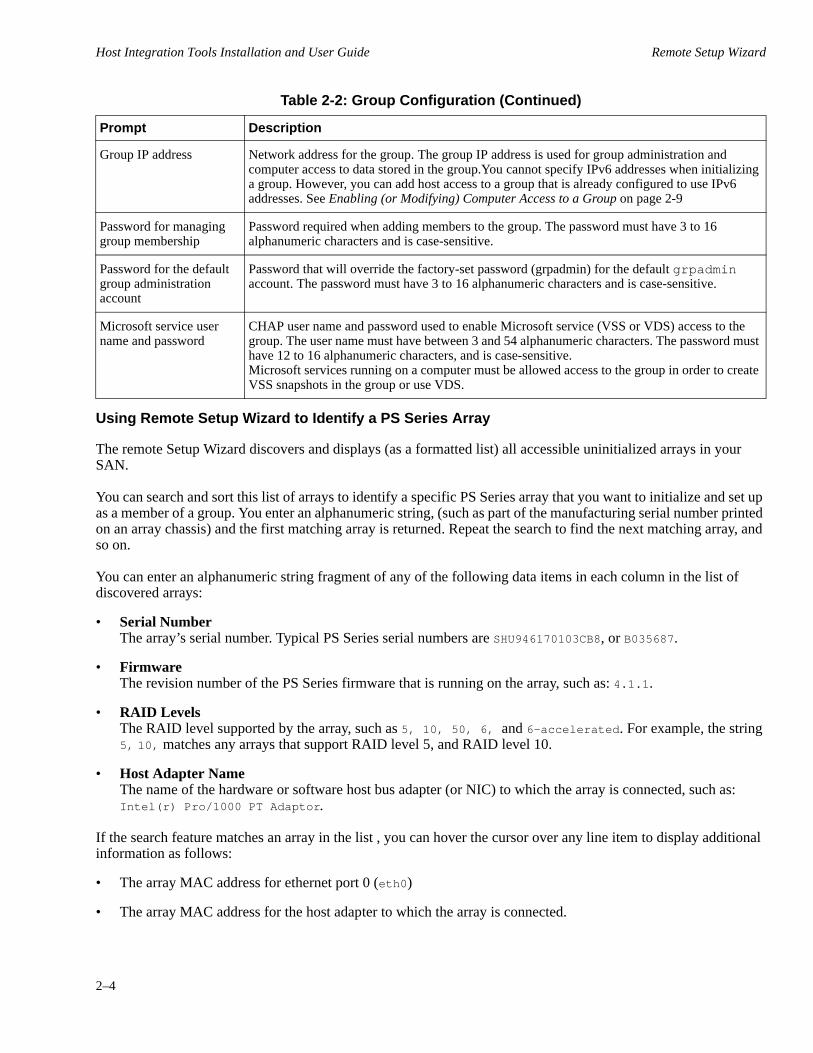
Table 2-2: Group Configuration
Prompt Description
Group name Unique name used to identify the group. The name string must be fewer than 64 alphanumeric characters or hyphens. No other characters are permitted. The first character must be a letter or number.
Host Integration Tools Installation and User Guide Remote Setup Wizard
2–4
Using Remote Setup Wizard to Identify a PS Series Array
The remote Setup Wizard discovers and displays (as a formatted list) all accessible uninitialized arrays in your SAN.
You can search and sort this list of arrays to identify a specific PS Series array that you want to initialize and set up as a member of a group. You enter an alphanumeric string, (such as part of the manufacturing serial number printed on an array chassis) and the first matching array is returned. Repeat the search to find the next matching array, and so on.
You can enter an alphanumeric string fragment of any of the following data items in each column in the list of discovered arrays:
• Serial NumberThe array’s serial number. Typical PS Series serial numbers are SHU946170103CB8, or B035687.
• FirmwareThe revision number of the PS Series firmware that is running on the array, such as: 4.1.1.
• RAID LevelsThe RAID level supported by the array, such as 5, 10, 50, 6, and 6-accelerated. For example, the string 5, 10, matches any arrays that support RAID level 5, and RAID level 10.
• Host Adapter NameThe name of the hardware or software host bus adapter (or NIC) to which the array is connected, such as: Intel(r) Pro/1000 PT Adaptor.
If the search feature matches an array in the list , you can hover the cursor over any line item to display additional information as follows:
• The array MAC address for ethernet port 0 (eth0)
• The array MAC address for the host adapter to which the array is connected.
Group IP address Network address for the group. The group IP address is used for group administration and computer access to data stored in the group.You cannot specify IPv6 addresses when initializing a group. However, you can add host access to a group that is already configured to use IPv6 addresses. See Enabling (or Modifying) Computer Access to a Group on page 2-9
Password for managing group membership
Password required when adding members to the group. The password must have 3 to 16 alphanumeric characters and is case-sensitive.
Password for the default group administration account
Password that will override the factory-set password (grpadmin) for the default grpadmin account. The password must have 3 to 16 alphanumeric characters and is case-sensitive.
Microsoft service user name and password
CHAP user name and password used to enable Microsoft service (VSS or VDS) access to the group. The user name must have between 3 and 54 alphanumeric characters. The password must have 12 to 16 alphanumeric characters, and is case-sensitive. Microsoft services running on a computer must be allowed access to the group in order to create VSS snapshots in the group or use VDS.
Table 2-2: Group Configuration (Continued)
Prompt Description

Host Integration Tools Installation and User Guide Remote Setup Wizard
2–5
You can also sort the list of discovered arrays by clicking on the button that contains a list column heading. For example, click on the Firmware heading to sort firmware revisions in ascending order. Click a second time to sort in descending order. A triangle to the right of the column header indicates the current sort column, if any, and the sort direction.
PS Series Array Initialization Procedure
Use the following procedure to initialize an array and create a group:
1. Start the Remote Setup Wizard. as described in Launching the Remote Setup Wizard on page 2-2. The Welcome dialog (Figure 2-1) appears.
Figure 2-1: Remote Setup Wizard - Welcome
2. Select the option to Initialize a PS Series array and click Next. A message notifies you that the remote Setup Wizard is discovering all uninitialized arrays accessible to the computer.A list of arrays is provided in the Select an Array to Initialize dialog (Figure 2-2).
Figure 2-2: Remote Setup Wizard - Select an Array to Initialize
Host Integration Tools Installation and User Guide Remote Setup Wizard
2–6
Note: If no arrays appear, click the Rediscover button. If arrays still do not appear, review the requirements described in Remote Setup Wizard Computer and Group Requirements on page 2-1.
3. Do either of the following:
– Select a PS Series array. (Hover the cursor over an array to see details.)
– Use the search feature described in Using Remote Setup Wizard to Identify a PS Series Array on page 2-4 to find and select a specific array or to sort the list of arrays.
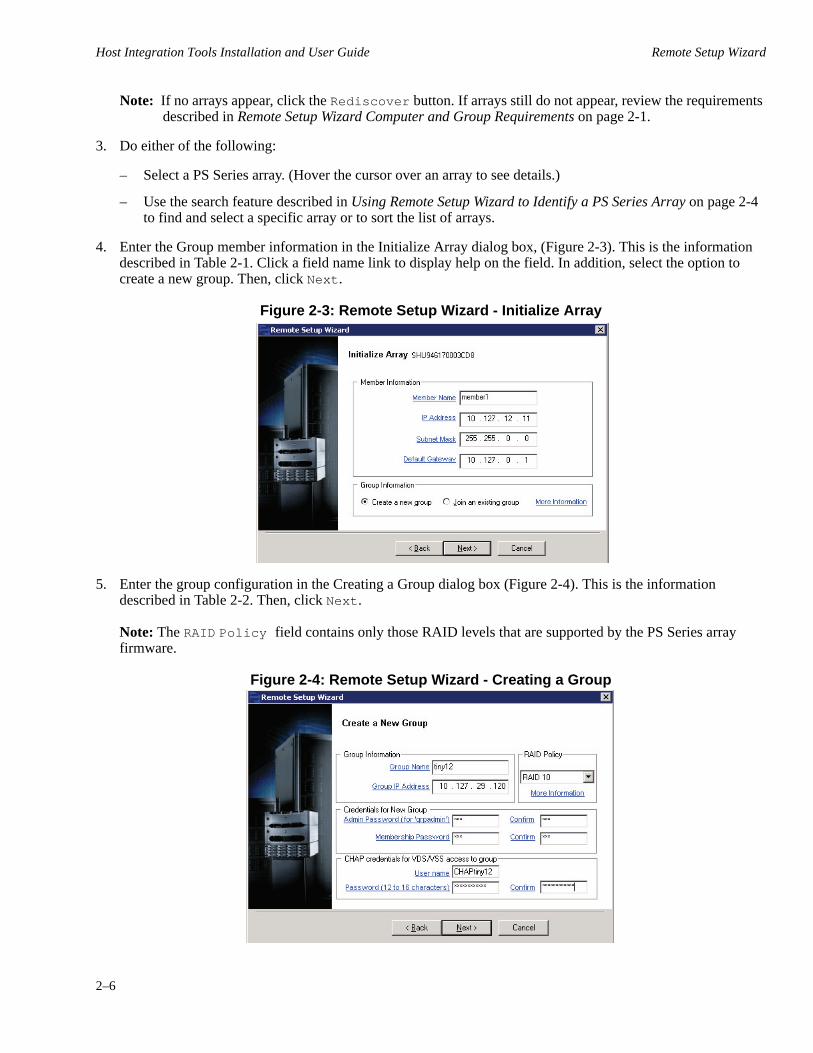
4. Enter the Group member information in the Initialize Array dialog box, (Figure 2-3). This is the information described in Table 2-1. Click a field name link to display help on the field. In addition, select the option to create a new group. Then, click Next.
Figure 2-3: Remote Setup Wizard - Initialize Array
5. Enter the group configuration in the Creating a Group dialog box (Figure 2-4). This is the information described in Table 2-2. Then, click Next.Note: The RAID Policy field contains only those RAID levels that are supported by the PS Series array firmware.
Figure 2-4: Remote Setup Wizard - Creating a Group

Host Integration Tools Installation and User Guide Remote Setup Wizard
2–7
6. Click OK. A message appears indicating that the array has been initialized and the Finish dialog box appears (Figure 2-5).
7. Select from the following options:
– View Log to display a summary of the configuration.
– Next to initialize another array and add it to the group.
– Finish to complete the configuration and exit the wizard.
Figure 2-5: Remote Setup Wizard - Finish
When you exit the wizard, it performs these tasks:
• Configures the group IP address as an iSCSI target discovery address. This enables the computer to discover volumes and snapshots (iSCSI targets) in the group.
• Stores the CHAP user name and password that allow Microsoft services (VDS or VSS) access to the group.
• Creates a corresponding VSS/VDS access control record and local CHAP account in the group. In the group, to view the VSS/VDS access control record, click Group Configuration, then click on the VDS/VSS tab.To display the local CHAP account in the group, click Group Configuration, then click on the iSCSI tab.
After you create a group, you can use the Group Manager GUI or CLI to create and manage volumes. If you are running Windows Server 2003 SP2, by default, the wizard launches Storage Manager for SANs (if it is installed), which also enables you to create and manage volumes.
Initializing an Array and Expanding a Group
Using the Remote Setup Wizard, you can initialize a PS Series array and add the array to an existing group. In addition, the wizard will configure the group IP address as an iSCSI discovery address on the computer.
Note: If the Remote Setup Wizard is interrupted while initializing an array and the operation fails, you must reset the array before running the wizard again. To reset an array, connect the serial cable that was shipped with the array to the active control module and to a console terminal or a computer running a terminal emulator. Then, enter the reset command.
Host Integration Tools Installation and User Guide Remote Setup Wizard
2–8
Before you initialize an array and expand a group, gather the information about the array configuration, as described in Table 2-1. You will also need the group name, IP address, and membership password, as described in Table 2-2. The Remote Setup Wizard will prompt you for this information. Consult your network administrator for the necessary IP addresses.
Use the following procedure to initialize an array and expand an existing group:
1. Start the Remote Setup Wizard, as described in Launching the Remote Setup Wizard on page 2-2.
2. Select the option to initialize an array in the Welcome dialog box (Figure 2-1) and click Next.
Note: If no arrays appear, click the Rediscover button. If arrays still do not appear, make sure you meet the requirements described in Remote Setup Wizard Computer and Group Requirements on page 2-1.
3. Select the array you want to initialize (Figure 2-2) and click Next.
4. Enter the member information in the Initialize Array dialog box (Figure 2-3). This is the information described in Table 2-1.Click a field name link to display help on the field. In addition, select the option to add the array to an existing group. Then, click Next.
5. Enter the group name and IP address and the membership password in the Joining a Group dialog box.
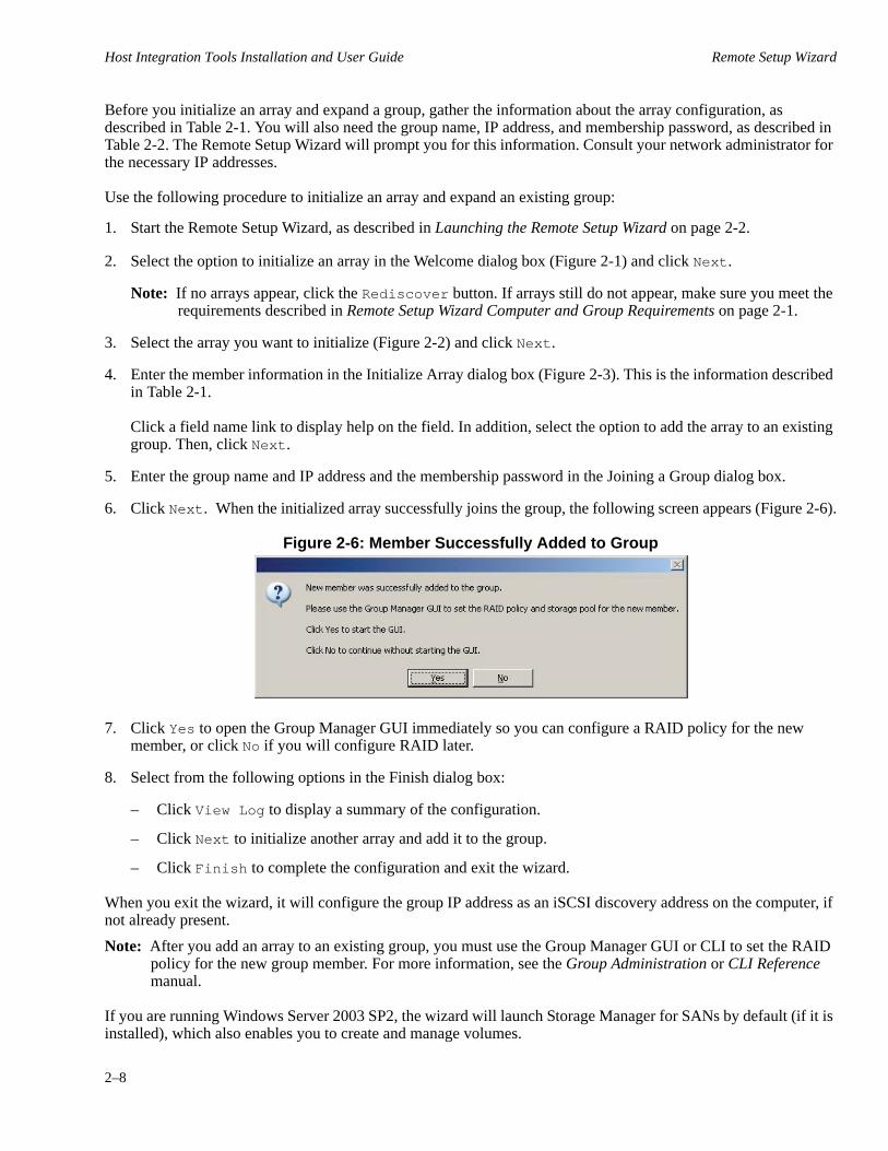
6. Click Next. When the initialized array successfully joins the group, the following screen appears (Figure 2-6).
Figure 2-6: Member Successfully Added to Group
7. Click Yes to open the Group Manager GUI immediately so you can configure a RAID policy for the new member, or click No if you will configure RAID later.
8. Select from the following options in the Finish dialog box:
– Click View Log to display a summary of the configuration.
– Click Next to initialize another array and add it to the group.
– Click Finish to complete the configuration and exit the wizard.
When you exit the wizard, it will configure the group IP address as an iSCSI discovery address on the computer, if not already present.
Note: After you add an array to an existing group, you must use the Group Manager GUI or CLI to set the RAID policy for the new group member. For more information, see the Group Administration or CLI Reference manual.
If you are running Windows Server 2003 SP2, the wizard will launch Storage Manager for SANs by default (if it is installed), which also enables you to create and manage volumes.

Host Integration Tools Installation and User Guide Remote Setup Wizard
2–9
Enabling (or Modifying) Computer Access to a Group
You can use the Remote Setup Wizard to enable Windows computer access to a PS Series group. You can also use the wizard to modify existing group access information on a computer (for example, if the group IP address changed).
Note: If you create a group using the Remote Setup Wizard, computer access to the group is automatically configured. This section applies only if you used Remote Setup Wizard on a different computer to create the group, or created the group by using a local serial cable connection instead of Remote Setup Wizard.
To access a group from a Microsoft Failover Cluster, make sure that you enable group access on all cluster nodes. You must do this for all nodes that are either active or passive users of any iSCSI volumes located in the group.
When you use the Remote Setup Wizard to enable computer access to a group, the wizard performs the following tasks on the computer:
• Configure the group IP address as an iSCSI target discovery address. This enables the computer to discover volumes and snapshots (iSCSI targets) in the group.
• Store the CHAP user name and password that allow Microsoft services (VDS or VSS) access to the group.
• Store the CHAP user name and password for ASM/ME access to Smart Copies of volumes on the group.
You require the information described in Table 2-3 to complete this procedure.
Table 2-3: Information Required for Group Access
Data Item Description
Group Name Unique access name for the group.
Group IP Address IP address of the group. You can specify IPv6 addresses if you already configured the group to use IPv6. (Use the Group manager GUI or CLI.)
CHAP Credentials for VDS/VSS access to group
The CHAP user name and password already configured in the group for Microsoft service (VSS or VDS) access to the group. To use the Group Manager GUI to display the VSS/VDS access control record, click Group Configuration, then click on the VSS/VDS tab.To display the local CHAP account in the group, click Group Configuration, then click on the iSCSI tab.
CHAP Credentials for access to Smart Copies
The CHAP user name and password already configured in the group to allow access to Smart Copies.
Use the following procedure to enable computer access to a group or modify existing group access information:
1. Launch the Remote Setup Wizard, as described in Launching the Remote Setup Wizard on page 2-2.
2. Select Configure this computer to access a PS Series SAN and click Next.
3. Select from the following options in the Configuring Group Access dialog box (Figure 2-7):
a. To add a group that the computer can access, click Add Group.

Host Integration Tools Installation and User Guide Remote Setup Wizard
2–10
b. To modify existing group access credentials, select the group and click Modify Group.
Figure 2-7: Remote Setup Wizard - Configuring Group Access
4. Specify or modify the group name and IP address, as needed in the The Add or Modify Group Information dialog box (Figure 2-8).
Figure 2-8: Remote Setup Wizard - Add or Modify Group Information
Also, complete the following fields as necessary:
a. If the group is configured to allow Microsoft service (VDS or VSS) access to the group through CHAP, specify the CHAP user name and password that matches the VSS/VDS access control record and local CHAP account already configured in the group.
b. If the PS Series group is configured to restrict discovery based on CHAP credentials, click the checkbox next to Use CHAP credentials for iSCSI discovery. If not, do not check this box.Click Save to return to the Configuring Group Access dialog box (Figure 2-7).

Host Integration Tools Installation and User Guide Remote Setup Wizard
2–11
c. If the group uses CHAP access control records to restrict access to its snapshots, specify the CHAP user name and password credentials for access to the snapshots.
6. Click Finish.
Disabling Microsoft Service Access to a Group
You can use the Remote Setup Wizard to disable access to a PS Series group by all Microsoft services (VSS and VDS) running on a computer. If you do this, the computer will not be able to use VDS to create volumes or use VSS to create Smart Copies in the group.
Alternately, you can disable a specific Microsoft service’s ability to access a group. To do this, run the installation program and deselect the components.
Use the following procedure to disable all Microsoft service access to a group:
1. Launch the Remote Setup Wizard, as described in Launching the Remote Setup Wizard on page 2-2. The Welcome dialog box, (Figure 2-1) appears.
2. Select the option to configure the computer to access a SAN (the group) and click Next. The Configuring Group Access dialog box (Figure 2-7) appears.
3. Select the group and click Remove Group.
4. Confirm that you want to remove access to the group.
5. Click Finish to complete the operation and close the wizard.
6. Use the iSCSI initiator to log out from the session if you have an active iSCSI session to the group's vss-control volume.
7. Restart the VDS, VSS, eqlvss, and eqlvdshwprv services.

3–1
3 Remote Setup Command Line Utility
The Remote Setup Command Line Utility (RSWCLI) provides an alternative to using the Remote Setup Wizard. It provides set up commands that you can execute at the Windows command prompt instead of using the GUI. Using the Remote Setup CLI, you can perform the following actions:
• Discover uninitialized PS Series Arrays. See Discovering a PS Series Array on page 3-2.
• Initialize a PS Series Array. See Initializing a PS Series Array on page 3-2.
• Add access to a PS Series Array group for a host. See Adding Access to the PS Series Array Group on page 3-3.
• List information for all of the PS Series Array groups that a host is configured to access. See Listing Accessible PS Array Groups on page 3-4.
• Modify the access settings for a PS Series Array group to which the host already has access. See Modifying Access to PS Series Array Group on page 3-5.
• Remove access to a PS Series Array group to which the host currently has access. See Removing Host Access to a PS Series Array Group on page 3-6.
• List or modify settings for MPIO. See Listing or Modifying MPIO Settings on page 3-6.
• List the subnets that are currently included and excluded for MPIO. See Listing Included and Excluded Subnets for MPIO on page 3-7.
• Include a subnet for use by MPIO. See Including a Subnet for Use by MPIO on page 3-8.
• Exclude a subnet from use by MPIO. See Excluding a Subnet for User By MPIO on page 3-9.
When you install the Remote Setup Wizard, the Remote Setup CLI is also installed. See Chapter 1, Installation. See the Host Integration Tools Release Notes for the latest information about the Remote Setup CLI.
General Command Syntax for the RSWCLI
The general command syntax is as follows:
rswcli [-]sub_command required_parameter=“argument” [-optional_parameter...]
The following constraints apply to the syntax:
• [-]sub_command — Prefix subcommands with a dash (-).
• “argument”— An argument requires quotation marks only when the argument variable contains an embedded space.
• Several parameters are mutually exclusive, and if more than one of these parameters are specified, it is treated as an error and causes the command to fail. The command parser automatically ignores any redundant parameters.
Entering Commands
The Remote Setup CLI (RSWCLI) executable is located under the default installation folder, or the folder that you specified for HIT during installation. The default folder is: C:\Program Files\EqualLogic\bin.
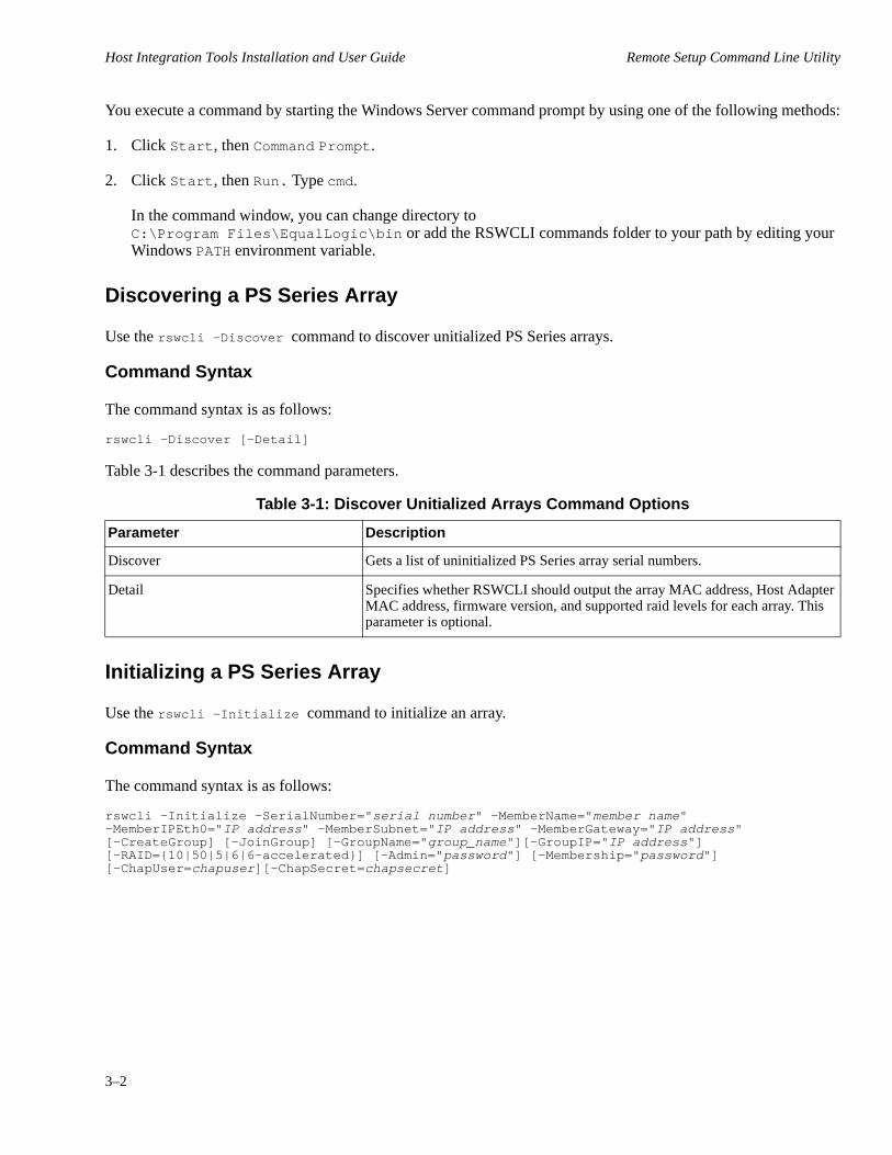
Host Integration Tools Installation and User Guide Remote Setup Command Line Utility
3–2
You execute a command by starting the Windows Server command prompt by using one of the following methods:
1. Click Start, then Command Prompt.
2. Click Start, then Run. Type cmd.In the command window, you can change directory to C:\Program Files\EqualLogic\bin or add the RSWCLI commands folder to your path by editing your Windows PATH environment variable.
Discovering a PS Series Array
Use the rswcli -Discover command to discover unitialized PS Series arrays.
Command Syntax
The command syntax is as follows:
rswcli -Discover [-Detail]
Table 3-1 describes the command parameters.
Table 3-1: Discover Unitialized Arrays Command Options
Parameter Description
Discover Gets a list of uninitialized PS Series array serial numbers.
Detail Specifies whether RSWCLI should output the array MAC address, Host Adapter MAC address, firmware version, and supported raid levels for each array. This parameter is optional.
Initializing a PS Series Array
Use the rswcli -Initialize command to initialize an array.
Command Syntax
The command syntax is as follows:
rswcli -Initialize -SerialNumber="serial number" -MemberName="member name" -MemberIPEth0="IP address" -MemberSubnet="IP address" -MemberGateway="IP address" [-CreateGroup] [-JoinGroup] [-GroupName="group_name"][-GroupIP="IP address"] [-RAID={10|50|5|6|6-accelerated}] [-Admin="password"] [-Membership="password"] [-ChapUser=chapuser][-ChapSecret=chapsecret]
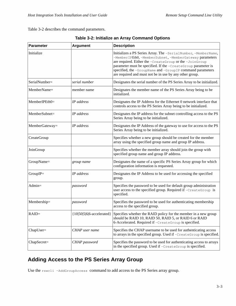
Host Integration Tools Installation and User Guide Remote Setup Command Line Utility
3–3
Table 3-2 describes the command parameters.
Table 3-2: Initialize an Array Command Options
Parameter Argument Description
Initialize Initializes a PS Series Array. The -SerialNumber, -MemberName, -MemberIPEth0, -MemberSubnet, -MemberGateway parameters are required. Either the -CreateGroup or the -JoinGroup parameter must be specified. If the -CreateGroup parameter is specified, the -GroupName and -GroupIP command parameters are required and must not be in use by any other group.
SerialNumber= serial number Designates the serial number of the PS Series Array to be initialized.
MemberName= member name Designates the member name of the PS Series Array being to be initialized.
MemberIPEth0= IP address Designates the IP Address for the Ethernet 0 network interface that controls access to the PS Series Array being to be initialized.
MemberSubnet= IP address Designates the IP address for the subnet controlling access to the PS Series Array being to be initialized.
MemberGateway= IP address Designates the IP Address of the gateway to use for access to the PS Series Array being to be initialized.
CreateGroup Specifies whether a new group should be created for the member array using the specified group name and group IP address.
JoinGroup Specifies whether the member array should join the group with specified group name and group IP address.
GroupName= group name Designates the name of a specific PS Series Array group for which configuration information is requested.
GroupIP= IP address Designates the IP Address to be used for accessing the specified group.
Admin= password Specifies the password to be used for default group administration user access to the specified group. Required if -CreateGroup is specified.
Membership= password Specifies the password to be used for authenticating membership access to the specified group.
RAID= {10|50|5|6|6-accelerated} Specifies whether the RAID policy for the member in a new group should be RAID 10, RAID 50, RAID 5, or RAID 6 or RAID 6-Accelerated. Required if -CreateGroup is specified.
ChapUser= CHAP user name Specifies the CHAP username to be used for authenticating access to arrays in the specified group. Used if -CreateGroup is specified.
ChapSecret= CHAP password Specifies the password to be used for authenticating access to arrays in the specified group. Used if -CreateGroup is specified.
Adding Access to the PS Series Array Group
Use the rswcli -AddGroupAccess command to add access to the PS Series array group.

Host Integration Tools Installation and User Guide Remote Setup Command Line Utility
3–4
Command Syntax
The command syntax is as follows:
rswcli -AddGroupAccess -GroupName="group name" -GroupIP="IP address" [-VSSVDSUser=VSS VDS user name] [-VSSVDSSecret=VSS VDS Password][-SmartCopyUser=Smart Copy Username] [-SmartCopySecret=Smart Copy Password] [-UseCHAPForDiscovery={yes|no}][-NoPing]
Table 3-3 describes the command parameters.
Table 3-3: Add Access to Group Command Options
Parameter Argument Description
AddGroupAccess Configures host access to a PS Series Array Group. The -GroupName and -GroupIP command parameters are required and must not be in use by any other group.
GroupName= group name Designates the name of a specific PS Series Array group for which configuration information is requested.
GroupIP= IP address Designates the IP Address to be used for accessing the specified group.
SmartCopyUser= CHAP user name Specifies the CHAP username to be used for authenticating access to smart copies on arrays in the specified group.
SmartCopySecret= password Specifies the password to be used for authenticating access to smart copies on arrays in the specified group.
UseCHAPForDiscovery= yes or no A boolean value that indicates whether CHAP authentication is used for discovery of iSCSI targets in the specified group.
NoPing Specifies whether RSWCLI should ping the specified IP Address to determine whether it is accessible by the host.
Listing Accessible PS Array Groups
Use the rswcli -ListGroup command to list information for all PS Series array groups.
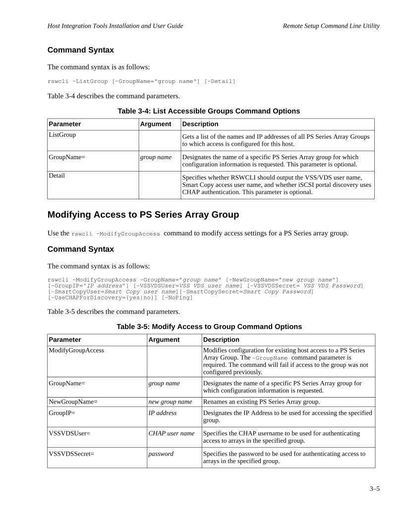
Host Integration Tools Installation and User Guide Remote Setup Command Line Utility
3–5
Command Syntax
The command syntax is as follows:
rswcli -ListGroup [-GroupName="group name"] [-Detail]
Table 3-4 describes the command parameters.
Table 3-4: List Accessible Groups Command Options
Parameter Argument Description
ListGroup Gets a list of the names and IP addresses of all PS Series Array Groups to which access is configured for this host.
GroupName= group name Designates the name of a specific PS Series Array group for which configuration information is requested. This parameter is optional.
Detail Specifies whether RSWCLI should output the VSS/VDS user name, Smart Copy access user name, and whether iSCSI portal discovery uses CHAP authentication. This parameter is optional.
Modifying Access to PS Series Array Group
Use the rswcli -ModifyGroupAccess command to modify access settings for a PS Series array group.
Command Syntax
The command syntax is as follows:
rswcli -ModifyGroupAccess -GroupName="group name" [-NewGroupName="new group name"] [-GroupIP="IP address"] [-VSSVDSUser=VSS VDS user name] [-VSSVDSSecret= VSS VDS Password] [-SmartCopyUser=Smart Copy user name][-SmartCopySecret=Smart Copy Password] [-UseCHAPForDiscovery={yes|no}] [-NoPing]
Table 3-5 describes the command parameters.
Table 3-5: Modify Access to Group Command Options
Parameter Argument Description
ModifyGroupAccess Modifies configuration for existing host access to a PS Series Array Group. The -GroupName command parameter is required. The command will fail if access to the group was not configured previously.
GroupName= group name Designates the name of a specific PS Series Array group for which configuration information is requested.
NewGroupName= new group name Renames an existing PS Series Array group.
GroupIP= IP address Designates the IP Address to be used for accessing the specified group.
VSSVDSUser= CHAP user name Specifies the CHAP username to be used for authenticating access to arrays in the specified group.
VSSVDSSecret= password Specifies the password to be used for authenticating access to arrays in the specified group.
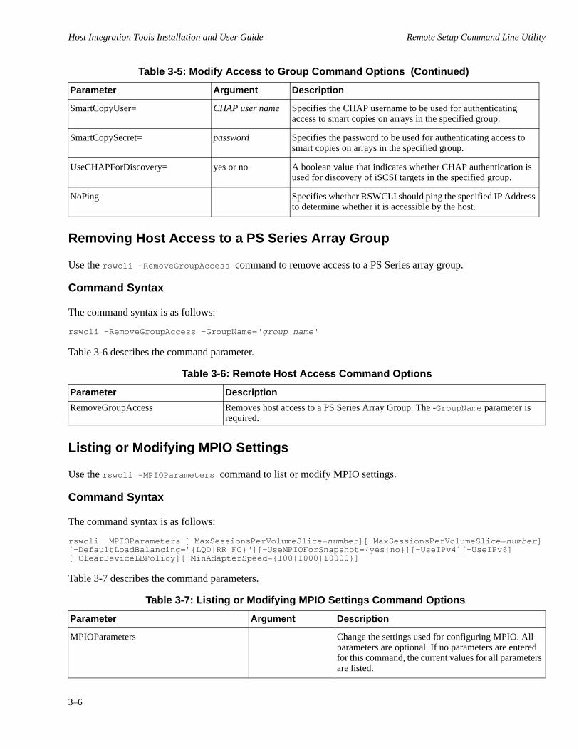
Host Integration Tools Installation and User Guide Remote Setup Command Line Utility
3–6
Removing Host Access to a PS Series Array Group
Use the rswcli -RemoveGroupAccess command to remove access to a PS Series array group.
Command Syntax
The command syntax is as follows:
rswcli -RemoveGroupAccess -GroupName="group name"
Table 3-6 describes the command parameter.
Table 3-6: Remote Host Access Command Options
Parameter Description
RemoveGroupAccess Removes host access to a PS Series Array Group. The -GroupName parameter is required.
Listing or Modifying MPIO Settings
Use the rswcli -MPIOParameters command to list or modify MPIO settings.
Command Syntax
The command syntax is as follows:
rswcli -MPIOParameters [-MaxSessionsPerVolumeSlice=number][-MaxSessionsPerVolumeSlice=number] [-DefaultLoadBalancing="{LQD|RR|FO}"][-UseMPIOForSnapshot={yes|no}][-UseIPv4][-UseIPv6] [-ClearDeviceLBPolicy][-MinAdapterSpeed={100|1000|10000}]
Table 3-7 describes the command parameters.
SmartCopyUser= CHAP user name Specifies the CHAP username to be used for authenticating access to smart copies on arrays in the specified group.
SmartCopySecret= password Specifies the password to be used for authenticating access to smart copies on arrays in the specified group.
UseCHAPForDiscovery= yes or no A boolean value that indicates whether CHAP authentication is used for discovery of iSCSI targets in the specified group.
NoPing Specifies whether RSWCLI should ping the specified IP Address to determine whether it is accessible by the host.
Table 3-7: Listing or Modifying MPIO Settings Command Options
Parameter Argument Description
MPIOParameters Change the settings used for configuring MPIO. All parameters are optional. If no parameters are entered for this command, the current values for all parameters are listed.
Table 3-5: Modify Access to Group Command Options (Continued)
Parameter Argument Description

Host Integration Tools Installation and User Guide Remote Setup Command Line Utility
3–7
Listing Included and Excluded Subnets for MPIO
Use the rswcli -ListMPIO command to list subnets that are included or excluded for MPIO.
Command Syntax
The command syntax is as follows:
rswcli -ListMPIO [-IncludeOnly] [-ExcludeOnly]
Table 3-8 describes the command parameters.
MaxSessionsPerVolumeSlice= 1-4 Designates the maximum number of connections that MPIO should use per volume per member.
MaxSessionsPerEntireVolume= 1-12 Designates the maximum number of connections that MPIO should use in per volume for all members.
DefaultLoadBalancing= {LQD|RR|FO} Specifies the default load balancing policy for MPIO as Least Queue Depth (LQD), Round robin (RR), or Failover Only (FO). This change does not affect existing device load balancing policy, unless the -ClearDeviceLBPolicy parameter is also specified.
UseMPIOForSnapshot= yes or no Specifies whether MPIO should be used for snapshots.
UseIPv4 Specifies that MPIO will use IPv4 IP addresses only. If this parameter is specified, the -UseIPv6 parameter cannot be specified.
UseIPv6 Specifies that MPIO used use IPv6 IP addresses only. If this parameter is specified, the -UseIPv4 parameter cannot be specified.
ClearDeviceLBPolicy Specifies that if the default load balancing policy is changed, then the load balancing policies for individual devices should be cleared if they are not set to use the default.
MinAdapterSpeed= {100|1000| 10000} Specifies that MPIO will only use NICs that meet the minimum speed specified in Mbps, if at least two meet the speed.
Table 3-8: List Subnets Command Options
Parameter Description
ListMPIO Lists the subnets that are included and excluded for use by MPIO. The optional -IncludeOnly and -ExcludeOnly are used to limit the output to the included subnets or the excluded subnets only. These parameters are mutually exclusive and the command will fail if both are specified.
IncludeOnly Specifies that the list should only contain the subnets that are included for use by MPIO. If this parameter is specified, the -ExcludeOnly parameter cannot be specified.
Table 3-7: Listing or Modifying MPIO Settings Command Options (Continued)
Parameter Argument Description

Host Integration Tools Installation and User Guide Remote Setup Command Line Utility
3–8
Including a Subnet for Use by MPIO
Use the rswcli -MPIOInclude command to include a subnet that is used by MPIO.
Command Syntax
The command syntax is as follows:
rswcli -MPIOInclude -Network="IP address" -Mask="IP address"
Table 3-9 describes the command parameters.
Table 3-9: Include a Subnet Command Options
Parameter Argument Description
MPIOInclude Moves a subnet that is in the MPIO excluded subnet list to the included subnet list. If the subnet defined by these arguments is not currently in the excluded subnet list, this command will fail.
Network= IP address Designates a new IP Address for a network that in combination with the -Mask parameter matches exactly a subnet that is in the excluded subnet list. This parameter is requried.
Mask= IP address Designates a subnet mask to be used in conjunction with the network IP address to define a subnet to be added to the include list. This parameter is requried.
ExcludeOnly Specifies that the list should only contain the subnets that are excluded from use by MPIO. If this parameter is specified, the -IncludeOnly parameter cannot be specified.
Table 3-8: List Subnets Command Options
Parameter Description

Host Integration Tools Installation and User Guide Remote Setup Command Line Utility
3–9
Excluding a Subnet for User By MPIO
Use the rswcli -MPIOExclude command to to exclude a subnet used by MPIO.
Command Syntax
The command syntax is as follows:
rswcli -MPIOExclude -Network="IP address" -Mask="IP address"
Table 3-10 describes the command parameters.
Table 3-10: Exclude a Subnet Command Options
Parameter Argument Description
MPIOExclude Moves a subnet that is in the MPIO included subnet list to the excluded subnet list. Both the -Network and -Mask parameters are required. If the subnet defined by these arguments is not currently in the excluded subnet list, this command will fail.
Network= IP address Designates a new IP Address for a network that in combination with the -Mask parameter matches exactly a subnet that is in the excluded subnet list.
Mask= IP address Designates a subnet mask to be used in conjunction with the network IP address to define a subnet to be added to the include list.


4–1
4 Using the Multipath I/O DSM
The EqualLogic Multipath I/O (MPIO) DSM (Device Specific Module) enables you to configure redundant network paths from a Windows computer to PS Series volumes for high availability and high performance SAN data traffic.
The following topics are included:
• Introduction to Multipath I/O DSM on page 4-1.
• Prerequisites for Configuring Multipath I/O DSM on page 4-3.
• Information Required to Configure Multipath I/O on page 4-4.
• Configuring Multipath I/O Between a Computer and a Group on page 4-4.
• Viewing MPIO Sessions on page 4-6.
• Setting the MPIO Load Balancing Policy on page 4-8.
• Excluding an IP Address from a Subnet on page 4-9.
Introduction to Multipath I/O DSM
The DSM coordinates activity between the Multipath I/O (MPIO) drivers and PS Series group storage, maximizing the capabilities of both the operating system and the iSCSI SAN.
The EqualLogic MPIO DSM provides the following features:
• Automatic connection management
• Increased bandwidth
• Reduced network latency
• Automatic path failure detection and failover to a functioning path
• Automatic load balancing across paths
• Support for multiple connections to a single iSCSI target (volume)
• Support for a variety of iSCSI initiators
The EqualLogic MPIO DSM works with the Microsoft iSCSI initiator and MPIO drivers to improve both reliability and performance. The MPIO DSM consists of the eqldsm.sys kernel mode driver and the EHCMservice.exe user mode service.
When you install the MPIO DSM on a Windows operating system, it establishes and manages multiple I/O data paths to the same iSCSI target (a PS Series volume). If a fatal path failure occurs, the failure is quickly detected and I/O transparently fails over to a functioning path. The MPIO DSM recognizes and responds to a variety of network errors, device errors, and timeout conditions.
Figure 4-1 shows a typical multipath I/O configuration.

Host Integration Tools Installation and User Guide Using the Multipath I/O DSM
4–2
Figure 4-1: Multipath I/O Configuration
Table 4-1 describes the callouts in figure Figure 4-1:
Table 4-1: Callouts in Figure 4-1.
1 The eqldsm.syskernel mode driver. (Performs I/O path selection and error handling.)
2 The EHCMservice.exe user mode service. (Manages iSCSI sessions.)
3 Two or more gigabit Ethernet (1 Gb/sec) NICs or HBAs.
4 Two or more (redundant) physical paths to dual redundant network switches.
5 Two or more (redundant) physical paths provide a network switch interlink.
6 Two or more (redundant) physical paths from the network switches. (Connected to the separate redundant controllers in each member in the PS Series Group.)
7 The PS Series group.
The number of paths created by the MPIO DSM depends on the topology of your SAN and the MPIO settings on the host computer. Every volume is distributed across one or more Members in the PS Series Group. The portion of a volume that is located on a single Member is referred to as a volume slice. The EHCMservice creates one or more iSCSI sessions to each volume slice. The default behavior is to create two sessions per volume slice. However, you can use the Remote Setup Wizard to modify the number of sessions, as described in Configuring Multipath I/O Between a Computer and a Group on page 4-4.
iSCSI sessions are distributed across all available adapters and PS Series Group Ethernet ports. The MPIO DSM does not establish entirely redundant paths (iSCSI sessions that have identical computer and array endpoints). Therefore, in configurations that have limited numbers of computer and array Ethernet ports, the actual number of sessions created may be less than you specify for the configuration. The EHCMService monitors the topology of the SAN. If you change the configuration, such as modify the number of Ethernet interfaces, or move a PS Series volume, it automatically reconfigures the MPIO DSM sessions.
Host Integration Tools Installation and User Guide Using the Multipath I/O DSM
4–3
Note: See the Release Notes for specific statements concerning supported Host Bus Adapter (HBA) hardware and firmware.
The MPIO DSM and PS Series Group firmware create secure CHAP credentials that enable only the EHCMService to add iSCSI sessions to a volume. These CHAP credentials are for internal use only and are not displayed by the Group Manager GUI or CLI.
The MPIO DSM also provides load balancing capabilities that enable you to maximize I/O throughput. The MPIO DSM has knowledge of the distributed nature of volumes on the PS Series Group, and uses this knowledge to route each I/O packet by using the optimal path to the volume.
Prerequisites for Configuring Multipath I/O DSM
Your computer must meet the following requirements to use Multipath I/O:
• A supported version of Windows, as specified in the Release Notes.
• The EqualLogic MPIO DSM is a subordinate module running within the Microsoft MPIO framework, and requires:
– For versions of Windows that support the Microsoft iSCSI Software Initiator as an installable application, you must have one of the Initiator versions specified in the Release Notes. You have the option to install a supported version of the Initiator automatically when you install the Host Integration Tools. If you choose to install the Microsoft iSCSI Initiator manually as an application, you must specify Microsoft MPIO support.
– For versions of Windows that include the Microsoft iSCSI Initiator as a service, you must either configure the Initiator service when you install Host Integration Tools tools, or configure the Initiator service as a post-installation task (before you run the Remote Setup Wizard).
– You must either configure the Microsoft MPIO service when you install Host Integration tools, or configure Microsoft MPIO as a post-installation task (before you run the Remote Setup Wizard).
• Two or more supported GigaBit Ethernet (or faster) network interface cards (NICs) or host bus adapters (HBAs). See the Release Notes for more information.
• For greatest redundancy, each host adapter must be connected to a different network switch.
The PS Series group must meet the following requirements to use multipath I/O:
• All group members (arrays) must be running the correct firmware revision, as specified in the Release Notes.
• Each PS Series group member must have at least two, and preferably three, connected and configured network interfaces.
• For greatest redundancy, connect the PS Series network interfaces to different network switches.
Consider also your local network configuration. A typical iSCSI SAN configuration provides two groups of communication interfaces. One group is dedicated to storage data traffic, and a second group is dedicated to general LAN traffic, computer intercommunication, and other purposes. Normally, these networks are discrete and maintained on separate subnets.
To maximize bandwidth, the MPIO DSM automatically uses any available network interfaces. When you configure MPIO DSM, consider restricting its access to subnets dedicated to iSCSI data traffic.

Host Integration Tools Installation and User Guide Using the Multipath I/O DSM
4–4
Information Required to Configure Multipath I/O
To configure multipath I/O, you need the data specified in Table 4-2.
Table 4-2: Configuring Multipath I/O
Prompt Description
Subnets included The IP address range for subnets (in IPv4 or IPv6 format) that you intend to use for multipathing.
Subnets excluded The IP address range for subnets (in IPv4 or IPv6 format) that you intend to exclude from multipathing.
Load balancing policy By default, the MPIO DSM applies a policy of least queue depth. You can optionally select fail over only or round robin. See Setting the MPIO Load Balancing Policy on page 4-8 for a complete description of these options.
Max sessions per volume slice For volumes that span multiple group members, you can specify the maximum sessions permitted for a volume per group member. Select a value n in the range 1-4.
Max sessions per entire volume For volumes that span multiple group members, you can specify the maximum session permitted for the volume. Select a value n in the range 1-12, where n is greater than or equal to the value of the max sessions per volume slice.A value that is three times the max sessions per volume slice is typical because volumes typically span up to three members. Reduce this value if you want to reduce the total number of session established to a volume.
Use MPIO for snapshots You can specify whether to use MPIO when connecting to snapshots.
Use IPv6 or IPv4 You can specify whether to use IPv4 (the default) or IPv6, if configured.
Minimum adapter speed You can specify the slowest acceptable speed that a NIC can have when used for MPIO. The choices are based on the speeds of the NICs available on the host machine. If only one speed is available, this field is read-only.
Configuring Multipath I/O Between a Computer and a Group
Use the following procedure to configure multipath I/O between a computer and a group:
1. Make sure you meet the requirements in Prerequisites for Configuring Multipath I/O DSM on page 4-3.
2. Install the Remote Setup Wizard and the Multipath I/O DSM on the computer, as described in Installing the Host Integration Tools on page 1-7.
3. Start the Remote Setup Wizard, as described in Launching the Remote Setup Wizard on page 2-2. The Welcome dialog box appears (Figure 2-1).
4. Select the option to configure MPIO settings and click Next. The Configure MPIO Settings dialog box appears. By default, all subnets are configured for multipath I/O.
5. Exclude a subnet by moving it from the left panel to the right panel.
Host Integration Tools Installation and User Guide Using the Multipath I/O DSM
4–5
Note: To exclude a specific IP address on a subnet, you must manually edit the registry variables. See Excluding an IP Address from a Subnet on page 4-9.
6. [Optional] Change the load balancing policy. If you are unsure about which load balancing policy to specify, Dell recommends that you use the default setting of Least Queue Depth.
7. [Optional] Modify the minimum adapter speed.
8. Click Finish to complete the multipath I/O configuration. Click Back to make changes.
Changes to the list of included or excluded subnets are effective immediately for new connections, while changes to existing connections might take several minutes.
To verify that you correctly configured Multipath I/O, use the procedures described in Viewing MPIO Sessions on page 4-6.
Logging into a Volume with Multipath I/O
After you configure multipath I/O and create volumes on the PS Series group, you can connect to those volumes and enable multipathing to the volumes.
To log in to a volume and configure multiple connections:
1. Start the iSCSI Initiator Properties control panel.
2. Click the Targets tab after discovery of the group targets is complete.
3. Select the target, and click Log On. The Log On to Target dialog appears.
4. Select options as follows:
a. If you need to enter CHAP credentials, click Advanced, enter the information, and click OK.
b. You do not need to select the Enable multi-path option unless there is an existing iSCSI session to the volume.
5. Click OK.
After you log on to a target, the Multipath I/O DSM automatically creates additional connections to that target.
Note: The Multipath I/O DSM does not manage persistent connections to iSCSI targets. For maximum redundancy on a computer with multiple adapters, Dell recommends that you create persistent logins to each target for each adapter.
Logging Off a Volume with Multipath I/O
To log off a volume with multiple connections under Windows Server 2008 R2:
1. Click the Targets tab and select the target.
2. Click Disconnect.
To log off a volume with multiple connections when using other Windows variants, you must select and log out of each connection session as follows:
Host Integration Tools Installation and User Guide Using the Multipath I/O DSM
4–6
1. Click the Targets tab, select the target, and click Details. The Target Properties dialog box is displayed.
2. Click the Sessions tab.
3. Select all sessions and click Log Off.
Note: If you see a message warning you that a device is in use, wait a few seconds, click the Refresh button, then repeat step 3.
Viewing MPIO Sessions
The status of the MPIO DSM is logged for display in the EqualLogic MPIO tab of the iSCSI Initiator properties page. The properties page appears when you double-click the Initiator icon, or when you launch the Initiator interface from the Windows control panel.
The status tab provides:
• Details of the NIC or HBA adapters present in the system, identifying which adapters support MPIO.
• The status of MPIO sessions and paths.
Data is stored in a cumulative log file at: <installation_path>\EqualLogic\Logs\ehcm.log. When the current log file is full, the logger renames it to ehcm0.log and deletes the previous log (that is, only one previous log file is retained.)
To adjust the length of history stored, you can change the size of the log file by modifying the Windows registry entry under: HKEY_LOCAL_MACHINE\SOFTWARE\Equallogic\EHCM.
The following value limits apply:
Key Default Minimum Maximum
XMLLogsize 10 (MB) 1 50
The ehcmn.log file provides data for a custom MPIO properties tab in the iSCSI initiator properties pages (Figure 4-2). When you launch the initiator properties, it might take up to a minute to load data from the log.
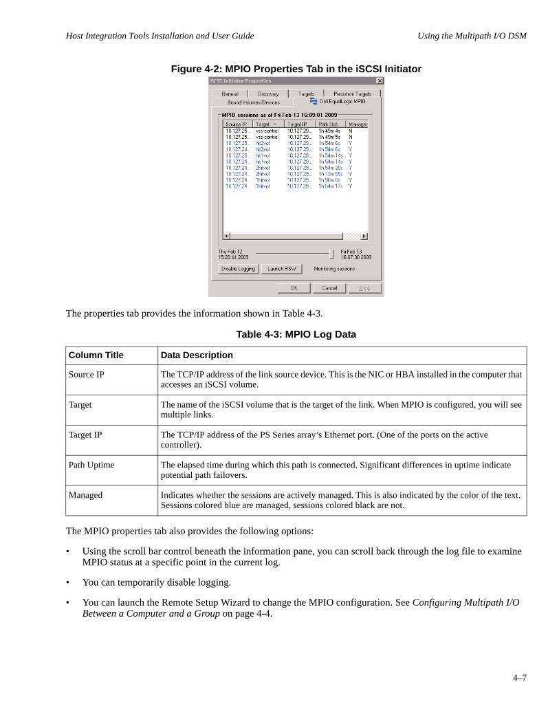
Host Integration Tools Installation and User Guide Using the Multipath I/O DSM
4–7
Figure 4-2: MPIO Properties Tab in the iSCSI Initiator
The properties tab provides the information shown in Table 4-3
Table 4-3: MPIO Log Data
Column Title Data Description
Source IP The TCP/IP address of the link source device. This is the NIC or HBA installed in the computer that accesses an iSCSI volume.
Target The name of the iSCSI volume that is the target of the link. When MPIO is configured, you will see multiple links.
Target IP The TCP/IP address of the PS Series array’s Ethernet port. (One of the ports on the active controller).
Path Uptime The elapsed time during which this path is connected. Significant differences in uptime indicate potential path failovers.
Managed Indicates whether the sessions are actively managed. This is also indicated by the color of the text. Sessions colored blue are managed, sessions colored black are not.
.
The MPIO properties tab also provides the following options:
• Using the scroll bar control beneath the information pane, you can scroll back through the log file to examine MPIO status at a specific point in the current log.
• You can temporarily disable logging.
• You can launch the Remote Setup Wizard to change the MPIO configuration. See Configuring Multipath I/O Between a Computer and a Group on page 4-4.

Host Integration Tools Installation and User Guide Using the Multipath I/O DSM
4–8
Setting the MPIO Load Balancing Policy
When you have configured multiple data pathways, it is appropriate to configure MPIO DSM to balance data traffic loads across the pathways. Dell recommends the default setting of Least Queue Depth, which is appropriate for most installations.
Your options are:
• Fail Over Only – MPIO DSM uses one connection for all SAN data traffic until it times out or otherwise fails. At that time, traffic fails over to any other available path. Selecting this load balance policy causes the EHCMservice to no longer add and remove additional sessions to the target.
• Round Robin – MPIO DSM sends SAN data traffic packets over each available connection in a rotating sequence, fully utilizing all available paths.
• Least Queue Depth – MPIO DSM sends SAN data traffic packets out to each available connection, with preference given to the connection that is least busy at the time it requests the I/O.
Note: For both Round Robin and Least Queue Depth policies, sessions to the Group member containing the data are given preference over other sessions.
Procedure to display the connections to a target and optionally change its load balancing policy on operating systems other than Windows Server 2008 R2:
1. Double-click the Microsoft iSCSI Initiator to display its Properties.
2. Click the Targets tab and click a target (volume) that has a status of Connected to highlight and select that target.
3. Click the Details button to display the Target Properties for the selected volume and then click the Devices tab to display devices.
4. Verify that the entry in the MPIO Capable column is Multi-Path Support. If the entry is anything other than that (such as Disk Drive), it means that either the Microsoft MPIO DSM is not properly installed, or there is a problem recognizing an HBA as MPIO-compliant.
5. Click the Advanced button to display the Device Details, and click the MPIO tab.
6. Use the pull-down menu underneath Load Balance Policy to configure the policy for this device.
Notes: If you view the sessions tab, be aware that the MPIO DSM does not use multiple connections per session. Therefore the Load Balance Policy setting accessible through the Connections button has no effect.If the MPIO tab does not appear in the initiator control panel, you might not have selected MPIO support when installing the initiator, or you might need to reboot the computer to complete the installation.
Procedure to display the connections to a target and optionally change its load balancing policy on Windows Server 2008 R2:
1. Double-click the Microsoft iSCSI Initiator to display its Properties.
2. Click the Targets tab and click a target (volume) that has a status of Connected to highlight and select that target.
Host Integration Tools Installation and User Guide Using the Multipath I/O DSM
4–9
3. Click the Devices button to display devices.
4. Click the MPIO button.
5. Use the pull-down menu underneath Load balance Policy to configure the policy for this device.
Note: If you view the sessions tab, be aware that the MPIO DSM does not use multiple connections per session. Therefore the Load Balance Policy setting accessible through the Properties button has no effect. If the MPIO tab does not appear in the initiator control panel, you might not have selected MPIO support when installing the initiator, or you might need to reboot the computer to complete the installation.
Excluding an IP Address from a Subnet
By default, when you configure the Multipath I/O DSM to include a subnet, all the IP addresses on the subnet are configured for multipathing. However, there might be cases where you want to exclude individual IP addresses on a subnet.
For example, your computer could have three network interface cards (NICs) that are all on the same subnet as the PS Series group, but you only want to use two of the NICs for iSCSI connections to the group volumes.
Note: The computer will automatically exclude any addresses that cannot reach the PS Series group.
To exclude individual IP addresses (from an included subnet), you must use the Remote Setup Wizard CLI command rswcli –MPIOExclude, specifying a single address and a subnet mask of 255.255.255.255.
Example: rswcli –MPIOExclude –Network=”10.127.1.2” –Mask=”255.255.255.255”


5–1
5 Using the VDS Provider
The EqualLogic Virtual Disk Service (VDS) provider enables you to use Microsoft VDS V1.1 and Microsoft Storage Manager for SANs to create and manage volumes in a PS Series group.
VDS provider topics include:
• VDS Provider Requirements on page 5-1
• VDS Provider Guidelines and Restrictions on page 5-1
• Creating a Volume Using Storage Manager for SANs on page 5-3
See the Host Integration Tools Release Notes for the latest information about the VDS provider.
VDS Provider Requirements
Windows and PS Series group requirements for VDS are as follows:
• PS Series group running the minimum supported revision.
• A supported version of Microsoft Windows Server (See the Release Notes).
• On the computer, a supported version of the Microsoft iSCSI Software Initiator (See the Release Notes).
• On the computer, you must install the VDS provider, as described in Installing the Host Integration Tools on page 1-7.
• Access to the PS Series group by Microsoft services (VDS and VSS) running on the computer. See the ASM/ME User’s Guide for more information.
VDS Provider Guidelines and Restrictions
Use the VDS provider in conjunction with Microsoft VDS V1.1 and Storage Manager for SANs to create and manage volumes in a PS Series group. Guidelines and useful information about these configurations are:
• Storage PoolsThe EqualLogic VDS provider provides support for storage pools on Windows Server 2008 R2 and later platforms. This enables you to use a VDS management application such as DiskRAID to enumerate and create LUNs in storage pools other than the default pool.
• Provisioning VolumesDell recommends that you select a method by which to provision volumes and use that method consistently to create and manage volumes, with the exception of activities that explicitly require a particular method. For example, if you create a volume using Storage Manager for SANs, use that method to manage the volumes, except when you must use Group Manager to modify snapshot settings and configure replication.
• Access ControlsIf you are using Microsoft Storage Manager for SANs to create a volume in a PS Series group, it automatically creates access controls for the volume. If CHAP is used, the user name is always the iSCSI initiator name (as required by Microsoft VDS rules). You can also specify a password. Storage Manager for SANs then automatically creates a corresponding access control record and local CHAP account, if CHAP is used, in the

Host Integration Tools Installation and User Guide Using the VDS Provider
5–2
group. Always use Storage Manager for SANs to manage these access controls.However, for a volume created with Storage Manager for SANs, you can use the Group Manager GUI or CLI to create additional access controls in the group. Always use Group Manager to manage these access controls.
• Snapshot SettingsA volume created with Storage Manager for SANs inherits the group-wide snapshot settings (snapshot reserve, warning percentage, and space recovery policy).
• VDS Volumes in Group ManagerVolumes created by using Storage Manager for SANs appear in the Group Manager Volume Access window with yes in the VDS column.
Simple Target and LUN Naming
The EqualLogic VDS provider implements the simple target configuration. When you use Storage Manager for SANs to create a LUN, the EqualLogic VDS provider automatically creates an iSCSI target and associates that target with the LUN. When you delete a LUN, VDS deletes the associated iSCSI target. You cannot independently manage LUNs and targets.
A target's iSCSI name and friendly name is based on the LUN name for ease of use. Because the LUN name is not specified at LUN creation time, the EqualLogic VDS provider delays setting these target names to allow the creator to first set a more descriptive LUN name. Dell recommends that VDS clients set the friendly name before querying the target properties so that the desired friendly name can be used in the target name. When a VDS client has queried the properties of the associated target, the iSCSI name cannot be changed even if the LUN name is updated. The target's friendly name will continue to be updated on LUN name changes so the two values match.
When using Storage Manager for SANs or diskraid to create a LUN, the LUN friendly name is correctly set before the target is created. If you use Storage Manager for SANs to create multiple LUNs, wait until each LUN is created and displayed before creating any additional LUNs. This avoids a situation in which two LUNs are created and renamed simultaneously, which can result in the target name on the second LUN being created before the LUN name is set.
Importing VSS Snapshots
To import VSS snapshots of a volume that you created by using Storage Manager for SANs, the computer must present access credentials. The credentials must match an access control record that you configured in the PS group for all snapshots related to the volume:
1. Configure an access control record in the PS group that applies to the target volume’s snapshots.
2. [Optional] Configure a local CHAP account in the PS group only if you protected access to snapshots by using CHAP. Do either of the following:
– Specify the same CHAP user name and password that you specified when you created the volume.
– Specify different credentials.
3. Specify the CHAP username and password when prompted, or use ASM/ME to specify the user name and password in the Properties Password dialog box. This user name and password now applies to all VSS snapshots created in the group and accessed from the computer.

Host Integration Tools Installation and User Guide Using the VDS Provider
5–3
Modifying Access Controls
If you change access controls related to Microsoft service access to the PS Series group or computer access to VSS snapshots, make sure you make the necessary changes on both the computer and the group as follows:
• For volumes created by using Storage Manager for SANs, use the same method to change the access controls on both the computer and the group.
• For VSS snapshots of volumes created with Storage Manager for SANs:
– Use the Group Manager GUI or CLI to modify the snapshot access control records and CHAP accounts, if CHAP is used.
– On the computer, use the ASM/ME Properties Password dialog box to specify the CHAP user name and password.
• For Microsoft service access to the group:
– Use the Remote Setup Wizard to modify the computer configuration.
– In the group, use the Group Manager GUI or CLI to modify VSS/VDS access control records and CHAP accounts, if CHAP is used.
Creating a Volume Using Storage Manager for SANs
To use Microsoft Storage Manager for SANs to create a volume in a PS Series group, configure the group and install the VDS provider.
Volumes created with Storage Manager for SANs use the default group-wide volume snapshot settings for snapshot space, warning level, and action to take when snapshot space is exceeded. You can use the Group Manager GUI or CLI to change the snapshot settings.
When Storage Manager for SANs creates a volume in a group, it automatically creates access controls for the volume. If CHAP is used, the user name is always the iSCSI initiator name. You can optionally specify a secret (password).
Storage Manager for SANs automatically creates an access control record in the group with matching access controls, in addition to a local CHAP account, if you use CHAP.
Note: The volume access controls that Storage Manager for SANs creates in the group also apply to snapshots of the volume. Once these credentials are assigned, you cannot change them using the Group Manager GUI or CLI. Instead, you must use Storage Manager for SANs to change the CHAP credentials. You can set up additional access controls for a volume created with Storage Manager for SANs by using normal Group Manager access control records.
Starting the Storage Manager for SANs
To start Storage Manager for SANs, click Start, then Administrative Tools, then Storage Manager for SANs.
Note: Because of the way it gathers storage information, the Microsoft Storage Manager for SANs application incorrectly reports the total capacity and used space of a EqualLogic group. Use the Group Manager GUI to obtain accurate free space information. You can also use the Provision Storage Wizard (found within Storage Manager for SANs), which reports the size of actual storage space available on the group as maximum volume size.

Host Integration Tools Installation and User Guide Using the VDS Provider
5–4
See the Storage Manager for SANs documentation for more information about using this utility.
6–1
6 Using the EqualLogic HPC iSCSI Provider
Microsoft supports iSCSI storage in its High-Performance Compute Cluster software, HPC Server. This support appeared in the 2008 R2 version. iSCSI support allows HPC nodes to boot from iSCSI volumes, and allows the HPC server to provision those volumes. To enable all this, a vendor-specific HPC iSCSI Provider is required. Host Integration Tools version 3.4 includes this provider.
HPC iSCSI Provider Installation
The HPC iSCSI Provider is installed automatically with the rest of the Host Integration Tools kit. If you are building an HPC Server, you should install the Microsoft HPC Server package first, followed by the Host Integration Tools kit. During installation, the Host Integration Tools kit registers its iSCSI Provider with the HPC Server, enabling the HPC Server's iSCSI provisioning.
If you uninstall and then reinstall the HPC Server, you will need to reinstall the Host Integration Tools kit so that it can re-register with the HPC Server.
Configuring the PS Series Array
The HPC iSCSI Provider requires an array running at least version 5.0 of the PS Series array firmware. Previous firmware versions do not support template volumes, which are required by the iSCSI Provider.
In order to use the EqualLogic HPC iSCSI Provider, you will need to enable access to the VDS/VSS Control Volume on your PS Series array. The easiest way configure access to the VDS/VSS Control Volume is using Remote Setup Wizard. See Chapter 2, Remote Setup Wizard for instructions.
If access to the VDS/VSS Control Volume is not configured, the HPC iSCSI Provider will report errors like “failed to create tunnel to group” when attempting to set up volumes for HPC nodes.
Settings
The HPC iSCSI Provider has a number of settings. These can be changed using a graphical tool, EqlHPCSettings.exe. This tool is available from the Start menu. To launch it, click Start, then All Programs, then Equallogic, then HPC iSCSI Provider Settings.
The HPC iSCSI Provider Settings screen is shown in Figure 6-1.

Host Integration Tools Installation and User Guide Using the EqualLogic HPC iSCSI
6–2
Figure 6-1: HPC iSCSI Provider Settings
The settings for the HPC iSCSI Provider are described in Table 6-1.
Table 6-1: HPC iSCSI Provider Settings
Setting Default Value Description
New Volume Size
80,000 MB The size of all volumes created by the iSCSI HPC Provider. All HPC volumes are created thin-provisioned, so they will not occupy this much space on the group. Changing this value will not affect existing volumes already created by HPC.
Pool Name for HPC Volumes
default The pool in which to create the volumes. This pool must exist on the PS Series array in use.
Base Volume Provisioning
10%, 80%, 100% When thin-provisioned volumes are created, they are assigned a minimum, maximum and warning level value. The minimum value is the amount of storage to assign to the volume immediately. As data is written to the volume, additional storage will be assigned to it as needed. If the assigned storage reaches the warning level, the PS Series array will issue an alert. Once the assigned storage reaches the maximum value, no further storage can be assigned to the volume. For base volumes, the minimum volume reserve cannot be less than 10%.
Difference Volume Provisioning
0%, 80%, 100% These parameters have the same effect as the base volume provisioning parameters, but apply to differencing volumes.

Host Integration Tools Installation and User Guide Using the EqualLogic HPC iSCSI
6–3
Create new volumes with open ACLs
no Normally the HPC server maps a volume to a given node, which causes an ACL to be set on the volume. In some cases this may cause problems, particularly if the HBA is not using the IQN string the HPC Server has assigned to it during boot. Selecting this option will cause all volumes created by the iSCSI Provider to be assigned an unrestricted ACL, meaning that any initiator will be able to connect. You should only enable this option if you are experiencing authorization failures when nodes attempt to log into their assigned volumes.
Table 6-1: HPC iSCSI Provider Settings (Continued)
Setting Default Value Description


7–1
7 Tools and Utilities
The Host Integration Toolkit includes the following utilities:
• EqlXcp Utility — Accelerates file copy operations by using SCSI Extended Copy commands.
• EqlLog Utility — Gathers logging information into a zip file in the My Documents folder. You can then send this file to customer support for debugging.
The EqlXcp Utility
EqlXcp is a command-line Windows utility that uses SAN Data Copy Offload—an API that accelerates file copy operations by using SCSI Extended Copy commands. In a standard file copy operation, data is read from the source volume to the host computer, and then written to the destination volume. With SCSI Extended Copy commands, the source volume can transmit the data directly to the destination volume. The host computer is therefore eliminated from the I/O path, and network utilization is drastically reduced.
EqlXcp Utility Restrictions
If any of the following rules are not met, the EqlXcp utility will exit with an error message. No data will be lost.
• To use this utility, you must have the SE_MANAGE_VOLUME_NAME privilege. Administrators have this privilege by default.
• You can only copy between volumes on a single group.
• The source and destination volumes must reside on a PS Series array.
• The array must be running PS Series firmware version 5.0 or higher.
• You cannot use this utility on compressed or sparse files. (Sparse files are files that are thin-provisioned on the NTFS filesystem).
• EqlXcp is not supported on volumes that are cluster resources.
Using the EqlXcp Utility
The EqlXcp utility is located under the default installation folder, or the folder that you specified for HIT during installation. The default folder is: C:\Program Files\EqualLogic\bin.
1. Click Start, then Run. Type cmd.
2. In the command window, you can change the directory to C:\Program Files\EqualLogic\bin
3. Entering eqlxcp alone displays the syntax for the utility:
eqlxcp [switches] source-file destination-file
4. To copy file1.zip to a new file called file2.zip, enter the following command:
eqlxcp e:\file1.zip e:\file2.zip

Host Integration Tools Installation and User Guide Tools and Utilities
7–2
Debug Tracing and the EqlLog Utility
The Host Integration Tools kit includes a trace logging utility, EqlLog, that collects HIT trace logs, VSS logs, VDS logs, cluster logs, install logs, event logs, Setup API logs, backup documents, and MSInfo output. If you ever have an issue with the Host Integration Tools kit that requires customer support, you will be asked to run the this utility, which gathers all of the logging information into a zip file in the My Documents folder. You can then send this file to customer support for debugging.
Running the EqlLog utility
The EqlLog utility is located under the default installation folder, or the folder that you specified for HIT during installation. The default folder is: C:\Program Files\EqualLogic\bin. To run the utility:
1. Click Start, then Run. Type cmd.
2. In the command window, change the directory to C:\Program Files\EqualLogic\bin
3. Enter eqllog. The utility will gather trace logs and system information, and place them in a timestamped zip file, located in the My Documents folder.
EqlLog Command Line Options
The EqlLog utility has several command line options, listed in Table 7-1, which you can use to change its behavior.
Table 7-1: EqlLog CLI Options
Option Description
-h, --help Display usage information
-s, --short Capture only the last 2 hours of HIT and event logs. This can greatly reduce the size of the data collected when you know the error occurred very recently.
-D, --destdir=dir Changes the output directory where the .zip file is placed.
--no-hitlogs Do not collect miscellaneous HIT logs.
--no-backupdocs Do not collect VSS backup documents.
--no-msinfo Do not collect system information from MSInfo32.
--no-setupapi Do not collect Setup API logs.
--no-vss Do not collect VSS logs.
--no-vds Do not collect VDS logs.
--no-cluster Do not collect cluster logs.
--no-install Do not collect HIT installer logs.
--no-event Do not collect Windows event logs.

Host Integration Tools Installation and User Guide Tools and Utilities
7–3
Trace Log Daemon
The Trace Log Daemon collects trace log output from HIT components and outputs it to a single file, called called eqltrace.log. This file is one of several other components that the EqlLog utility gathers into a single zip file for bug reports.
EqlLog will automatically locate this file. eqltrace.log takes up 50MB of space by default. On Windows XP and Server 2003, eqltrace.log is located in <boot drive>:\Documents and settings\AllUsers\ApplicationData\EqualLogic\log. In later versions of Windows, it will be in <boot drive>:\ProgramData\EqualLogic\log.
There is usually no need to change trace log settings for the daemon. However, default values can still be overridden in the registry if necessary. For example, trace logging can be run at levels 0 (no tracing) to 3 (verbose tracing). The normal logging level is 2. You should not need to change this, but it can be controlled with the DebugLevel registry entry.
The registry values in Table 7-2 are located in HKLM/Software/EqualLogic/LogD. If a value is not present in the registry, the default value from the table will be used.
In previous versions, debug trace settings were controlled separately for each HIT component, using registry values. These old values are obsolete and no longer used; setting them will have no effect. Tracing for all HIT components is now controlled by a single registry value, and is on by default.
Table 7-2: User-Changeable Settings for the Trace Log Daemon
Parameter Default Value Type Definition
MaxLogSizeMB 50 DWORD Maximum size of the trace log file, in MB. When the file exceeds this limit, the daemon will rename the existing log to eqltrace.0.log and create a new eqltrace.log to continue logging.
DebugLevel 2 DWORD Controls the level of debug tracing. Other options are 0 (no tracing) to 3 (verbose tracing). 2 is full tracing.
Note: You do not need to restart the machine to change debug settings; the changes will automatically take effect within a few minutes.

Glossary–1
Glossary
This glossary defines the storage technology terminology that is specific to EqualLogic. If a term has unique meaning in the context of hardware or of a specific software application, that context is indicated.
See The SNIA Dictionary (http://www.snia.org/education/dictionary/) for definitions of any industry-standard storage terms used in this manual.
.bcd
(Auto-Snapshot Manager) The file extension used by ASM to identify a Smart Copy backup document.
.pvss
(Auto-Snapshot Manager) The file extension used by ASM to identify a Smart Copy backup document that has been mounted at least once.
access control list (ACL)
A list of permissions attached to an object such as a storage volume. See access control record.
access control record
Means by which you restrict/control access to a PS Series volume. To ensure that only authorized computers and users can access a PS Series volume (iSCSI target), use access control records. You can restrict volume access by using any combination of specific IP addresses, iSCSI initiators, or CHAP user name and password (secret).
access credentials
Identity information that is checked against access control records. A computer must match the credentials specified in an access control record in order to connect to a volume. See access control record.
active control module
(hardware) In a dual control module array, the control module that is actively serving I/O on a network. If it ceases to function, it fails over to the secondary control module. See secondary control module.
application component
(Auto-Snapshot Manager) Any part of an application that ASM supports for Smart Copy operations.
application component (node)
(Auto-Snapshot Manager) Objects in the ASM console tree that represent components of software applications, such as SQL Server or Microsoft Exchange.
applications
(Auto-Snapshot Manager) Installed applications for which a VSS writer is available, such as Microsoft Exchange or SQL Server.
applications master node
(Auto-Snapshot Manager) The location of applications and their components in the ASM console tree.
apply logs
(Auto-Snapshot Manager) An ASM option that enables you to apply database transaction logs manually to a restored database.
array
(hardware) A PS Series storage array is a completely self-contained storage unit that includes multiple disk drives configured in a highly available RAID set with dual control modules and redundant power supplies and cooling modules.
Group Administration Glossary
Glossary–2
array serial number
(Auto-Snapshot Manager) A unique PS Series array identification string that is encoded in the array's hardware. See service tag.
ASM/ME
(Auto-Snapshot Manager) Auto-Snapshot Manager/Microsoft Edition, a snap-in console application for the Microsoft Management Console that enables you to administer Smart Copies.
ASM/VE
(Auto-Snapshot Manager) Auto-Snapshot Manager/VMware Edition, a web-based application that works with VMware virtual environments to enable you to administer Smart Copies.
ASMCLI
(Auto-Snapshot Manager) A set of Smart Copy operation commands that you can execute at the Windows command prompt.
automatic RAID configuration
Internal process that configures the user-selected RAID policy on a member's disk array.
backup document
(Auto-Snapshot Manager) A file residing on the host that describes a Smart Copy on the PS Series array.
backup type
(Auto-Snapshot Manager) Specifies the backup behavior type that you want to create, either copy or full.
backup validation on startup
(Auto-Snapshot Manager) Automatically validate Smart Copies when ASM is started.
bandwidth
Rate at which an I/O subsystem or component can transfer bytes of data. Also called the transfer rate.
base volume
1. (Auto-Snapshot Manager) A PS series array volume mounted on the computer and reachable through its Windows-assigned drive letter (such as G:) or mount point.
2. (Group Manager) A volume that has snapshots. Snapshots depend on the base volume. If the base volume is destroyed, the snapshots have been removed.
broken smart copies
(Auto-Snapshot Manager) Smart Copies for which the storage on the array has been deleted, or is unreachable.
CHAP
Challenge Handshake Authentication Protocol, a network login protocol that uses an encrypted challenge-response mechanism. Used to limit access to volumes and snapshots to hosts that supply the correct account name and password. CHAP is also used for login/administrator accounts. See access credentials.
CHAP account
An account that uses CHAP configured locally or on an external RADIUS server.
CHAP properties
(Auto-Snapshot Manager) An ASM configuration option that enables you to specify CHAP credentials for VSS or VDS access to groups and for computer access to Smart Copies for importing.
checksum verification
(Auto-Snapshot Manager) The process of verifying the integrity of Microsoft Exchange Smart Copies. You use the Windows eseutil.exe, a database maintenance utility.
Group Administration Glossary
Glossary–3
cloning
The process of creating a new copy of an object such as a volume. The new object is the same type and has the same contents as the original. Contrast with a thin clone.
collection
(Auto-Snapshot Manager) Related groups of volumes or application components. These objects are represented by nodes in the ASM Console Tree under the Collections master node. Create collections of related volumes that you copy frequently. This ensures that ASM creates all the relevant Smart Copies simultaneously in one set. Create, modify, or delete a collection, create a Smart Copy Set for the collection, or configure a schedule for the collection.
command generation
(Auto-Snapshot Manager) The process of using the ASM GUI to generate an ASMCLI command.
console pane
(Auto-Snapshot Manager) The section of the ASM GUI that contains the console tree. This pane contains a collapsing, branched structure of related groups of clickable objects on which you can perform many different operations. See console tree.
console tree
(Auto-Snapshot Manager) A hierarchical structure of branched nodes representing objects on which ASM can perform operations. Nodes represent objects such as applications, volumes, and collections. The ASM console tree consists of related groups of objects (nodes) organized in a branching tree structure. Depending on the status of a node, you are presented with a menu of actions in the Actions Pane. See console pane.
control module
(hardware) The processor and interface component in a PS Series array. A control module contains the PS Series firmware in flash memory and provides temporary power continuity for data stored in cache memory. It has multiple network interfaces and an optional serial port. An array can contain two hot-swappable, dual redundant controllers. The active control module serves I/O, while the secondary control module mirrors data in its cache.
cooling module
(hardware) Hot-swappable hardware component, optionally integrated with a power supply, that provides cooling to a PS Series array. Arrays are shipped with redundant cooling modules. An array can continue to operate if one cooling module fails.
defer verification
(Auto-Snapshot Manager) When creating a replica, this operation causes ASM to defer Checksum Verification and Soft Recovery of Microsoft Exchange Smart Copies to a later time. Invoke the procedure manually or create a schedule at some future time.
delegated space
(Group Manager) Space on a group set aside to store received replicas for a partner.
demote
(Group Manager) Convert a volume in a replication configuration into a replica set.
device-specific module (DSM)
(Host Integration Tools) A plug-in for Microsoft Windows device driver module. For multipath implementation on PS Series arrays, you use EqualLogic Multipath I/O DSM in conjunction with Microsoft MPIO. It provides the EHCMservice.exe user mode Windows service, and the eqldsm.sys kernel mode driver.
DSM
See device-specific module (DSM).
failback
(Group Manager) Replicating only the volume changes (delta) from the secondary group to the primary group and then returning to original replication configuration.
Group Administration Glossary
Glossary–4
failback baseline
Date and time at which the data in the failback snapshot is identical to the data represented by the most recent replica.
failback replica set
(Group Manager) Temporary replica set created by demoting a volume as part of a failback operation. You can also create failback thin clone replica sets. See demote.
failback snapshot (baseline)
(Group Manager) A snapshot on the primary group containing the same data as the most recent complete replica, defining the failback baseline. A failback snapshot enables you to fail back to the primary group by replicating only the changes made to the recovery volume.
fan tray
(hardware) See cooling module.
global Smart Copy access
(Auto-Snapshot Manager) Refers to access controls that allow other computers to access (import) Smart Copies created on a particular computer.
global verification task
(Auto-Snapshot Manager) A scheduled background activity that you can run from any designated user account. The Global Verification Task performs Checksum Verification and Soft Recovery processing on Exchange Smart Copies.
global verification window
(Auto-Snapshot Manager) A time period in which ASM can perform Checksum Verification and Soft Recovery on Smart Copies of Microsoft Exchange Storage Groups and mailbox databases. You typically specify a range of time that corresponds with a period of low system usage (off-peak times) to make best use of server resources.
group
See PS Series group.
group access
1. (Auto-Snapshot Manager).The process of enabling computer access to a PS Series Group by configuring and supplying credentials. See access credentials and CHAP.
2. (Group Manager) Access to the Group Manager UIs for management purposes. Access the GUI or CLI though the network. You can access the CLI through the optional serial port on the controller.
3. (hardware) Access to the group storage. iSCSI initiators access group iSCSI targets through the group IP address (discovery address). Access to a specific target is controlled through the access controls assigned to the target.
group administrator
An account on a PS Series group that has permission to manage all features and objects in a PS Series group, including configuring replication partners. The default group administrator account is grpadmin. See pool administrator.
group IP address
The network address that iSCSI initiators use to discover iSCSI targets and administrators use to access the group. See management IP address
group member
See member.
Group Administration Glossary
Glossary–5
group name
A unique identifier assigned to a group.
Host Integration Tools
(HIT) A suite of applications that enable you to configure and manage an array. It includes ASM/ME, DSM (Multipath I/O Device Specific Module), and RSW (Remote Setup Wizard).
hot-swap
(hardware) Removing a redundant component and installing a replacement while the array is running.
imported Smart Copy credentials
(Auto-Snapshot Manager) When a computer imports a Smart Copy, it must automatically present default credentials that match one of the Smart Copy’s access control records.
iSCSI host bus adapter (HBA)
(hardware) An iSCSI initiator implemented as a physical I/O adapter through which a computer connects to a physical storage device such as a volume.
iSCSI portal verification
(Auto-Snapshot Manager) Verifying that ASM can connect to arrays to which it previously connected when last active.
jumbo frames
Ethernet frames capable of more than 1,500 bytes of payload (MTU). Enabling jumbo frames might improve performance on certain configurations.
keep count
1. (Auto-Snapshot Manager) The maximum number of snapshots or replicas retained by a Smart Copy schedule.
2. (Group Manager) The user-established limit on the number of snapshots or replicas created by using a schedule on the PS Series group.
latency
The time required to complete a specific I/O operation.
load balancing
Automatic distribution of I/O across resources to improve performance.
local replication reserve
(Group Manager) Storage space on a primary group that is used to record changes to a volume when replication is configured, and optionally to store a failback snapshot for a volume.
management IP address
In a group with a management network configured and enabled, an address used exclusively to log into the Group Manager GUI or CLI.
management network
An optional management network separates iSCSI traffic (volume I/O) from management traffic (GUI and CLI sessions, and other group management communications and intergroup operations).
manual restore
(Auto-Snapshot Manager) Mounting a Smart Copy and manually restoring data items.

Group Administration Glossary
Glossary–6
manual transfer replication
(Host Integration Tools, Group Manager) Replication done through transportable media instead of over a network. Used in cases where the network link between replication partners is too slow or otherwise unsuitable for transferring large amounts of data.
Manual Transfer Utility
A stand-alone utility from EqualLogic that performs volume replication using transportable media, instead of the network. The utility has both graphical and command line user interfaces.
member
A PS Series array configured into a PS Series group. Groups can have several members.
member name
The unique name used to identify a specific member within a group.
membership password
The password required to add an array to a group, making it a member of the group.
merging pools
(Group Manager) The process of moving all the members and volumes from a source pool to a destination pool, deleting the source pool on completion.
mount
(Auto-Snapshot Manager) To create a connection to an iSCSI volume (clone, replica, or snapshot) and make its file system accessible to the operating environment.
MPIO
Acronym for multipath I/O. Multiple connections from an iSCSI initiator to targets on a PS Series Group over the network to provide redundancy and enhance performance. See device-specific module (DSM).
MPIO properties tab
(HIT) A EqualLogic-specific tab on the iSCSI Initiator properties page that provides status information about multipathing sessions. See MPIO.
notification
(Auto-Snapshot Manager, Group Manager) The method that a group uses to inform you of significant events through e-mail, remote syslog files, and SNMP traps.
path failover
(hardware, Host Integration Tools) Relocating data traffic from a failed network path to a functional network path. This can occur automatically if the computer's software and hardware is configured for failover. MPIO provides server-side path failover.
path uptime
The elapsed time during which a session is active, displayed in the MPIO properties tab.
pool
Storage space provided by one to four group members. You assign volumes to a specific pool and load balancing operates only within pools. See load balancing and merging pools
pool administrator
(Group Manager) An account on a PS Series group that has permission to manage objects only in a specific pool or set of pools for a group. Compare to group administrator.
power supply
(hardware) Hot-swappable hardware component, sometimes integrated with a cooling module, that enables you to connect a PS Series array to a source of power. Arrays are shipped with redundant power supplies. An array can
Group Administration Glossary
Glossary–7
continue to operate if one power supply fails. Dell recommends that you connect power supplies to different sources of power, preferably on separate circuits.
primary group
(Group Manager) In a replication partnership the group containing the original volume. See secondary group.
primary volume
(Group Manager) A volume configured for replication to a replication partner.
promote
(Group Manager) To convert a replica set in a replication configuration into a volume. See demote.
PS Series array
A single EqualLogic iSCSI storage unit, usually configured as a PS Series Group. You can join multiple PS Series arrays into a larger PS Series Group and manage them as a single iSCSI SAN.
PS Series group
An iSCSI storage entity comprised of one or more PS Series storage arrays that you access through a single IP address and manage as a storage area network (SAN).
Queue-depth reporting
(SAN HQ) The average number of outstanding I/O operations at the start of each incoming I/O operation.
RAID policy
The type of RAID level (such as RAID 10 or RAID 6) that you configure for a member, coupled with the sparing policy (spares or no spares).
read-only account
(Group Manager) An administration account that only provides read-only access to group information.
recovery volume
Temporary volume created by promoting an inbound replica set as part of a failover operation. You can also create recovery template volumes and recovery thin clones. See promote.
replica
A point-in-time representation of a PS Series volume. The original volume and its replica are located on different PS Series groups (replication partners) potentially separated at some geographical distance to facilitate disaster tolerance.
replica collection
(Group Manager) The set of replicas resulting from each replication of a volume collection.
replica collection set
(Group Manager) The set of replica collections for a volume collection.
replication partner
(Group Manager) A group that is configured to send or receive replicas from another partner.
replica reserve
(Group Manager) Portion of the delegated space on a replication partner that is set aside for the replica sets for a specific volume. You configure the replica reserve for the volume on the primary group, but the actual replica reserve is on the secondary group.
replica set
(Group Manager) Set of complete replicas for a volume, template volume, or thin clone volume.

Group Administration Glossary
Glossary–8
replication
(Group Manager) Copying volume data (only deltas) from the primary group, where the volume is stored, to the secondary group. Groups can be an unlimited distance apart. You can recover data from the secondary group, if necessary.
restore
1. (Auto-Snapshot Manager) The process of recovering data from a Smart Copy.
2. (Group Manager) The process of restoring the contents of a volume from a snapshot.
RSW
(HIT) Remote Setup Wizard, a graphical user interface (GUI) that enables you to configure a PS-Series array after you install the Host Integration Tools.
SAN HeadQuarters
(SAN HQ) Enables you to monitor multiple PS Series groups from a single graphical interface. It gathers and formats performance data and other important group information.
secondary control module
(hardware) Mirrors cache data from the active control module. If the active control module ceases to function, the secondary takes over network operations. See active control module.
secondary group
(Group Manager) In a replication configuration, the group that receives replicas of a source volume. See primary group.
service tag
(Group Manager) A unique ID assigned by Dell to particular equipment, for use by customer service.
shrink (volume)
(Group Manager) Decreasing the reported size of a volume.
Smart Copy
(Auto-Snapshot Manager) Point-in-time, application-consistent copy of objects in a PS Series group. Smart Copies can be of type snapshot, clone, or replica, depending on the edition of Auto-Snapshot Manager that you are using.
snapshot
A point-in-time representation of a PS Series iSCSI volume. Seen on the network as an iSCSI target. This is maintained in an array as deltas from the original volume.
snapshot collection
A set of snapshots resulting from a snapshot operation on a volume collection. See volume collection.
spare disk
(hardware) An unused disk in a PS Series array that is used automatically to replace a failed disk.
storage pool
(Group Manager) See pool.
template volume
Read-only volume from which you create thin clones.
thin clone
Volume that shares space with a template volume. Thin clones provide an efficient use of storage space for configurations with multiple volumes that have a large amount of common data.
Group Administration Glossary
Glossary–9
thin provisioning
(Group Manager) The process optimizing use of storage space in a group through over-allocation. An object (such as a volume) is attributed less physical space than is reported by the group to any computer that is connected to the volume.
torn Smart Copy
(Auto-Snapshot Manager) The resulting Smart Copy that contains only partial data. The partial data set is referred to as torn because it does not contain all the files in a particular data set. This situation can occur when you attempt to do a Smart Copy of data sets that span multiple volumes.
transportable
(Auto-Snapshot Manager) A characteristic of a Smart Copy that enables it to be created on one computer and then moved to another computer to be used.
unmanaged space
Delegated space capacity on the secondary group that is no longer accessible from the primary group.
vacate
(Group Manager) To remove a member from a group while the member remains online.
volume
Storage allocated by a PS Series group as an addressable iSCSI target.
volume collection
(Group Manager) A number of volumes grouped together for purposes of performing operations on the volumes simultaneously. See also snapshot collection and replica collection.
volume administrator
An account on a PS Series group that has permission to manage a quota of storage in one or more pools. A volume administrator can perform any volume operations, including replication, within their quota limit.
volume reserve
(Group Manager) Amount of space allocated to a volume from free pool space. Without thin provisioning, volume reserve is the same as reported size.
vss-control volume
(Auto-Snapshot Manager) A special logical volume that enables Microsoft VSS/VDS services to communicate with a PS Series array. The vss-control volume appears as a non-initialized disk in the Windows Disk Management interface.

Index–1
Index
Symbols
.iss file 1-12
A
access a group 2-1
accountadministrator 1-1ASM/ME cluster 1-5
actively managed session 4-7
adaptermultipath 4-2
administratoraccount 1-1group account 2-4
arrayfailed initialization 2-2network address 2-3network connection guidelines 1-6
ASM/ME admin account (cluster) 1-5
ASMCLIsyntax 3-1
audience i-vii
automated recovery 1-3
Auto-Snapshot ManagerSee ASM/ME 1-1
B
bandwidth 1-6, 4-1maximizing 4-3replication network 1-6
C
CD-ROM 1-9
CHAPauthentication 2-1, 2-2credentials 2-9credentials for Smart Copies 2-9group access 2-10local account 2-7MPIO DSM 4-3
password 2-4, 2-7, 2-9setting credentials for Smart Copies 2-11user name 2-4, 2-7, 2-9
cluster 2-9See Microsoft Failover Cluster 1-4
commandprompt 3-2reset 2-3
components 1-1, 1-10host integration tools 1-1
computerdisabling access to a group 2-11enabling access to a group 2-9
configureLAN 4-3MPIO 4-4MPIO DSM logging 4-6multipath 4-4multipath I/O 4-4network 4-3
connecting ports 1-6
connectionmanagement 4-1multiple iSCSI 4-1
considerationsHBA 4-3installation 1-7
console terminal 2-3
create group 2-1, 2-5
credentialsCHAP 4-3MPIO 4-3
customer support 1-9
D
dedicated subnet 4-3
defaultgateway 2-3load balancing 4-8
deinstalling software 1-11

Host Integration Tools Installation and User Guide Index
Index–2
device IP address 4-7
device specific moduleSee MPIO DSM 4-1
discovery address 2-1
distributed session 4-2
domain user account 1-5
driveinstallation 1-11
DSMSee MPIO DSM 4-1
E
ehcm.log 4-6
EHCMservice.exe 4-1
eqldsm.sys 4-1
EqlLog utility 7-2
EQLReqServicelogon account 1-6
EqlXcp utility 7-1
EqualLogicMultipath I/O DSM 1-2VDS Provider 1-2VSS Provider 1-1
Ethernetarray port 4-2gigabit 1-6port 0 2-2
Exchange ServerSee Microsoft Exchange Server 1-3
excludedIP addresses 4-9subnet 4-4
expand a group 2-1
F
fail over only 4-4, 4-8
failover 4-1paths 4-1
Failover ClusterSee Microsoft Failover Cluster 1-4
finding arrays 2-4
firewall 1-7
first time installation 1-9
flow control 1-6
friendly name 5-2
G
gateway 2-3
gigabit Ethernet 1-6
groupaccessing 2-1administration account 2-4administrator 1-1computer access to
disabling 2-11enabling 2-9
configuration, prompts 2-3creating 2-1enable cluster access 2-9expanding 2-1, 2-7IP address 1-6, 2-4multipath requirements 4-3multi-subnet 1-6name 2-3, 2-4network recommendations 1-6password 2-4
H
HBAfinding information 4-6support considerations 4-3
Host Integration Tools 1-1installing 1-7
Hyper-V 1-4
I
ICMP echo requests 1-7
IMPIO DSMminimum adapter speed 4-4
included subnet 4-4
initializationfailed 2-2
initializing an array using Remote Setup CLI 3-2
initiatorSee iSCSI initiator 4-1

Host Integration Tools Installation and User Guide Index
Index–3
installationconsiderations 1-7drive 1-11first time 1-9Host Integration Tools 1-7kit 1-9Microsoft Exchange Server 1-2preparation 1-9removing 1-11restart 1-11type 1-10unattended 1-11updating 1-11
IP addressdiscovery 2-1excluding from multipathing 4-9group 1-6source device 4-7
IP target 4-7
IPv4specifying for MPIO 4-4
IPv6 2-9, 4-4specifying for MPIO 4-4
iSCSImultiple connection 4-1
iSCSI initiator 1-2managing connections 4-1MPIO DSM properties 4-6
iSCSI volumesession per slice 4-4sessions per 4-4
J
Java Runtime Environment 1-2
jumbo frames 1-7
K
kernel mode driver 4-1
L
LANconfiguration 4-3
latency 4-1
layer 2 multicasting 2-2
least queue depth 4-4, 4-8
license agreement 1-9
load balancing 4-1, 4-5, 4-8default 4-8fail over only 4-4least queue depth 4-4policy 4-4, 4-8round robin 4-4
LUNsimple target 5-2target 5-2
M
max sessions 4-4
maximizing bandwidth 4-3
memberincreasing bandwidth 1-6multipath I/O 1-6network address 2-3network connection guidelines 1-6spanning 4-4subnet access 1-6
MicrosoftExchange checksum verification 1-3Exchange Server 2007 1-3Exchange soft recovery 1-3Exchange Storage Groups 1-3Exchange transaction log 1-3Exchange, installing under 1-2Failover Cluster 1-10, 2-9Failover Cluster admin account 1-5Hyper-V 1-4iSCSI Initiator 1-2services, VSS/VDS 2-4SQL Server. See SQL Server 1-3Storage manager for SANS 1-2VDS 1-2
Microsoft Failover Cluster 1-5
Minimum 4-4
minimum adapter speedspecifying for MPIO 4-4
MPIO DSMCHAP credentials 4-3configure 4-4configure logging 4-6configuring 4-4ehcm.log log file 4-6
Host Integration Tools Installation and User Guide Index
Index–4
exclude specific IP 4-9gigabit ethernet 1-6introduction to 4-1IPv4 4-4IPv6 4-4LAN 4-3log off volume 4-5log on volume 4-5logging 4-6multicasting 2-2on Failover Cluster 1-4path status 4-7properties tab 4-6properties tab (initiator) 4-7requirements 4-3snapshot connection 4-4status 4-6using 4-1
multicasting 2-2
multipathadapter 4-2configure 4-4displaying sessions 4-5exclude IP 4-9excluding subnet 4-9I/O
configure 4-4typical configuration 4-1
I/O DSM MPIO 1-2initator installation 4-8introduction 4-1load balancing 4-5logging in to volume 4-5logging off a volume 4-5requirements
computer 4-3group 4-3
selecting subnets 4-4
multiple connections 1-6
multi-subnet group 1-6
N
nameLUN 5-2target 5-2
netmask (member) 2-3
network
array IP address 2-3configuration 4-3connection guidelines 1-6exclude subnet 4-9gateway 2-3group IP address 2-4improving performance 1-6latency 4-1multiple connections 1-6non-blocking 1-6recommendations 1-6recommended switch 1-6replication requirements 1-6switch 1-6
NICSee HBA 4-6
non-blocking switch 1-6
O
online kit 1-9
operating systemguest 1-4supported 1-1
P
password 2-4
pathfailure 4-1redundant 4-2uptime value 4-7
policyload balancing. 4-8load blancing 4-4
port0 (zero) 1-6, 2-2connection sequence 1-6Ethernet 4-2
preparing to install 1-9
properties tabMPIO DSM 4-7
PS Series arrayfinding 2-4
R
RAID

Host Integration Tools Installation and User Guide Index
Index–5
policy 2-3RAID 10 2-3RAID 5 2-3RAID 50 2-3RAID 6 2-3RAID 6-Accelerated 2-3
reboot 1-11
redundant path 4-2
Release Notes 1-1, 1-2
Remote Setup CLI 3-1adding access to array group 3-3command syntax 3-1discover unitialized arrays 3-2exclude a subnet that MPIO uses 3-9include a subnet for use by MPIO 3-8initialize an array 3-2list accessible array groups 3-4list included and excluded subnets for MPIO 3-7list MPIO settings 3-6modify MPIO settings 3-6modifying access to array group 3-5remove access to array group 3-6
Remote Setup Wizardcomponent 1-1creating groups 2-2disabling computer access to a group 2-11enabling computer access to a group 2-9expanding groups 2-7failed initialization 2-2initializing array 2-2launching 2-2
remote Setup Wizardsearch feature 2-4
removing the software 1-11
replication 1-6network requirements 1-6
requirementsMPIO DSM 4-3multipath I/O 4-3
reset array 2-3
reset command 2-3
restartinstallation 1-11
restoreall (SQL) 1-3
all databases as new (SQL) 1-3clone and (SQL) 1-4named databases (SQL) 1-3
retrying array initialization 2-2
round robin 4-4, 4-8
RSWCLIbin folder 3-1entering commands 3-1
S
SANStorage Manager for 1-2topology 4-2
search for arrays 2-4
serial cable 2-3
sessionactively managed 4-7distribution 4-2maximum per slice 4-4per volume 4-4per volume slice 4-4
setup utilitygroup configuration prompts 2-3
setup.exe 1-12
simple target 5-2
slicevolume sessions per 4-4
softwarekit 1-9removing 1-11required 1-1
source IP 4-7
spanning-tree 1-7
SQL Server 1-32005 1-32008 1-3clone and restore 1-4restore all 1-3restore all as new 1-3restore named databases 1-3service pack 1-3version 1-3
statusMPIO DSM 4-6
Host Integration Tools Installation and User Guide Index
Index–6
Storage Group 1-3Recovery 1-3
Storage Manager for SANS 1-2
STPSee spanning tree 1-7
subnetdedicated 4-3exclude IP address 4-9excluded 4-4excluding 4-5, 4-9included 4-4
supportURL 1-9
supportedfirmware 1-1software 1-1
switchflow control 1-6jumbo frames 1-7network 1-6non-blocking 1-6recommendations 1-6, 1-7recommended network 1-6spanning-tree 1-7unicast storm control 1-7
syntaxcommand line 3-1verify subcommand 3-2, 3-4, 3-5, 3-6, 3-7, 3-8, 3-9
T
targetfriendly name 5-2IP address 4-7simple 5-2
target iSCSI volume 4-7
terminal emulator 2-3
The 3-1
topologychanging SAN 4-2SAN 4-2
transaction log 1-3
U
unattended installation 1-11
UNC format 1-10
unicast storm control 1-7
uninstalling software 1-11
updating an installation 1-11
URLsupport 1-9
user nameCHAP 2-4
V
VDS 2-4Microsoft 1-2Provider 1-2See Virtual Disk Service 5-1
VDS, See Virtual Disk Service 5-1, 5-3
versionMicrosoft Exchange Server 1-2
VHDSee virtual hard drive 1-4
virtualhard drive 1-4machine 1-4
Virtual Disk Servicecreating a volume 5-3features 5-1guidelines 5-1requirements 5-1restrictions 5-1
VLAN 1-7switch 1-7
volumelog off with MPIO 4-5log on with MPIO 4-5MPIO target 4-7session per slice 4-4sessions 4-4slice 4-2
volume slicesessions 4-4
VSS 2-1, 2-4provider 1-1
W
Web

Host Integration Tools Installation and User Guide Index
Index–7
software kit 1-9
X
XMLLogValue registry value 4-6