Embed Size (px)
Citation preview

Horizon QuantumTM
Wireless Ethernet Release 1.02.00
Product Manual - Volume 4 Networking Features
Version 1.1

Horizon Quantum Release 1.02.00 Wireless Ethernet Product User Manual – Volume 4
NOTICE This document contains confidential information, which is proprietary to DragonWave. No part of its contents can be used, copied, disclosed, or conveyed to any party in any manner whatsoever without prior written permission from DragonWave Inc.
Copyright © 2000 - 2012 DragonWave Inc.

Horizon Quantum Release 1.02.00 Wireless Ethernet Product User Manual – Volume 4
Table of Contents
1.0 USER MANUAL STRUCTURE ..................................................................................... 1
2.0 DRAGONWAVE LAYER 2 SWITCH (L2SW) .................................................................. 3
2.1 MANAGEMENT INTERFACE ................................................................................................................... 3
SAVING SWITCH PARAMETERS ................................................................................................... 3 2.1.1 BLOCKED COMMANDS ................................................................................................................ 4 2.1.2 CONTEXT SENSITIVE HELP ......................................................................................................... 5 2.1.3 CLI COMMAND MODES................................................................................................................ 6 2.1.4 PRIVILEGED EXEC MODE .......................................................................................................... 6 2.1.5 GLOBAL CONFIGURATION MODE ................................................................................................. 6 2.1.6 INTERFACE CONFIGURATION MODE ............................................................................................ 6 2.1.7 CONFIG-VLAN MODE ................................................................................................................ 7 2.1.8
2.2 SYSTEM COMMANDS .......................................................................................................................... 7 HELP ......................................................................................................................................... 7 2.2.1 DISABLE .................................................................................................................................... 8 2.2.2 CONFIGURE TERMINAL ................................................................................................................ 8 2.2.3 SET NETWORK MANAGEMENT INTERFACE ..................................................................................... 9 2.2.4 CONFIGURE TERMINAL .............................................................................................................. 10 2.2.5 END ......................................................................................................................................... 10 2.2.6 EXIT ........................................................................................................................................ 10 2.2.7 SHOW HISTORY ........................................................................................................................ 11 2.2.8
2.3 SYSTEM FEATURES .......................................................................................................................... 12
SWITCHPORT ........................................................................................................................... 12 2.3.1 INTERFACE-CONFIGURATION AND DELETION............................................................................... 13 2.3.2 NEGOTIATION ........................................................................................................................... 14 2.3.3 SPEED ..................................................................................................................................... 15 2.3.4 HOL BLOCKING PREVENTION ..................................................................................................... 16 2.3.5 DESCRIPTION ........................................................................................................................... 16 2.3.6 NO DESCRIPTION ...................................................................................................................... 16 2.3.7 DUPLEX ................................................................................................................................... 17 2.3.8 MTU FRAME SIZE ...................................................................................................................... 18 2.3.9
FLOWCONTROL ........................................................................................................................ 19 2.3.10 SHUTDOWN - PHYSICAL/VLAN/PORT-CHANNEL/TUNNEL INTERFACE ............................................ 20 2.3.11 DEBUG INTERFACE ................................................................................................................... 21 2.3.12 CLEAR COUNTERS .................................................................................................................... 22 2.3.13 SHOW INTERFACES................................................................................................................... 23 2.3.14 SHOW INTERFACES - COUNTERS ............................................................................................... 27 2.3.15 SHOW INTERFACE MTU ............................................................................................................. 29 2.3.16 SHOW FLOW-CONTROL ............................................................................................................. 30 2.3.17 SHOW DEBUGGING ................................................................................................................... 31 2.3.18 DEBUG LACP ............................................................................................................................ 31 2.3.19 SET IPG CONFIG ....................................................................................................................... 31 2.3.20 SHOW IPG CONFIG .................................................................................................................... 32 2.3.21 SHOW PORT-ISOLATION ............................................................................................................ 33 2.3.22 MONITOR SESSION ................................................................................................................... 34 2.3.23 SHOW MONITOR ....................................................................................................................... 34 2.3.24
2.4 SPANNING TREE PROTOCOL (STP) ................................................................................................... 35 RSTP ..................................................................................................................................... 35 2.4.1 MSTP ..................................................................................................................................... 35 2.4.2

DragonWave Inc. ii
Horizon Quantum Release 1.02.00 Wireless Ethernet Product User Manual – Volume 4
2.5 STP COMMANDS COMMON FOR RSTP AND MSTP ............................................................................ 35
SPANNING-TREE - PROPERTIES OF AN INTERFACE ...................................................................... 35 2.5.1 SHUTDOWN SPANNING-TREE ..................................................................................................... 39 2.5.2 SPANNING-TREE ....................................................................................................................... 41 2.5.3 SPANNING-TREE MODE ............................................................................................................. 42 2.5.4 SPANNING-TREE COMPATIBILITY ................................................................................................ 44 2.5.5 SPANNING-TREE TIMERS ........................................................................................................... 46 2.5.6 SPANNING-TREE TRANSMIT HOLD-COUNT ................................................................................... 48 2.5.7 CLEAR SPANNING-TREE COUNTERS ........................................................................................... 49 2.5.8 SPANNING-TREE PATHCOST DYNAMIC ........................................................................................ 50 2.5.9
SPANNING-TREE PRIORITY ........................................................................................................ 52 2.5.10 SPANNING-TREE AUTO-EDGE .................................................................................................... 54 2.5.11 SPANNING-TREE LAYER2-GATEWAY-PORT ................................................................................. 55 2.5.12 SPANNING-TREE BPDU-RECEIVE ................................................................................................ 57 2.5.13 SPANNING-TREE BPDU-TRANSMIT .............................................................................................. 58 2.5.14 SPANNING-TREE LOOP-GUARD .................................................................................................. 59 2.5.15 SPANNING-TREE PORTFAST ...................................................................................................... 60 2.5.16 DEBUG SPANNING-TREE............................................................................................................ 61 2.5.17 SHOW SPANNING-TREE - SUMMARY, BLOCKEDPORTS, PATHCOST, REDUNDANCY ........................ 64 2.5.18 SHOW SPANNING-TREE DETAIL .................................................................................................. 70 2.5.19 SHOW SPANNING-TREE ACTIVE.................................................................................................. 73 2.5.20 SHOW SPANNING-TREE INTERFACE ............................................................................................ 76 2.5.21 SHOW SPANNING-TREE ROOT .................................................................................................... 82 2.5.22 SPANNING-TREE GUARD ........................................................................................................... 85 2.5.23
2.6 MSTP ............................................................................................................................................. 86
SPANNING-TREE MST MAX-HOPS ............................................................................................... 86 2.6.1 SPANNING-TREE MST CONFIGURATION ....................................................................................... 87 2.6.2 SPANNING-TREE MST MAX-INSTANCE ......................................................................................... 88 2.6.3 SPANNING-TREE MST ROOT....................................................................................................... 89 2.6.4 SPANNING-TREE MST FORWARD-TIME ........................................................................................ 90 2.6.5 SPANNING-TREE MST MAX-AGE ................................................................................................. 91 2.6.6 NAME ...................................................................................................................................... 92 2.6.7 REVISION ................................................................................................................................. 92 2.6.8 INSTANCE ................................................................................................................................ 93 2.6.9
SPANNING-TREE MST- PROPERTIES OF AN INTERFACE FOR MSTP .............................................. 94 2.6.10 SPANNING-TREE MST HELLO-TIME ............................................................................................. 96 2.6.11 SHOW SPANNING-TREE MST - CIST OR SPECIFIED MST INSTANCE ............................................... 97 2.6.12 SHOW SPANNING-TREE MST CONFIGURATION ........................................................................... 100 2.6.13 SHOW SPANNING-TREE MST - PORT SPECIFIC CONFIGURATION ................................................ 102 2.6.14
2.7 VLAN ............................................................................................................................................ 105
SHUTDOWN VLAN ................................................................................................................... 105 2.7.1 SET VLAN ............................................................................................................................... 107 2.7.2 VLAN ..................................................................................................................................... 108 2.7.3 MAC-ADDRESS-TABLE STATIC UNICAST .................................................................................... 108 2.7.4 MAC-ADDRESS-TABLE STATIC UNICAST – TRANSPARENT BRIDGING MODE ................................. 110 2.7.5 MAC-ADDRESS-TABLE STATIC MULTICAST ................................................................................ 114 2.7.6 MAC ADDRESS-TABLE STATIC MCAST ....................................................................................... 116 2.7.7 MAC-ADDRESS-TABLE STATIC MULTICAST – TRANSPARENT BRIDGING MODE .............................. 117 2.7.8 MAC-ADDRESS-TABLE AGING-TIME .......................................................................................... 120 2.7.9
PORTS ................................................................................................................................... 121 2.7.10 VLAN ACTIVE .......................................................................................................................... 125 2.7.11 INTERFACE RANGE ................................................................................................................. 126 2.7.12 SWITCHPORT PVID .................................................................................................................. 127 2.7.13
Table of Contents iii
Horizon Quantum Release 1.02.00 Wireless Ethernet Product User Manual – Volume 4
SWITCHPORT ACCESS VLAN .................................................................................................... 128 2.7.14 SWITCHPORT PRIORITY DEFAULT ............................................................................................. 129 2.7.15 SWITCHPORT MODE ................................................................................................................ 129 2.7.16 DEBUG VLAN .......................................................................................................................... 132 2.7.17 SHOW VLAN ........................................................................................................................... 134 2.7.18 SHOW VLAN DEVICE INFO ........................................................................................................ 137 2.7.19 SHOW VLAN PORT CONFIG ...................................................................................................... 139 2.7.20 SHOW VLAN STATISTICS .......................................................................................................... 143 2.7.21 SHOW VLAN LEARNING PARAMS ............................................................................................... 145 2.7.22 SHOW MAC-ADDRESS-TABLE ................................................................................................... 147 2.7.23 SHOW MAC-ADDRESS-TABLE COUNT ........................................................................................ 149 2.7.24 SHOW MAC-ADDRESS-TABLE STATIC UNICAST .......................................................................... 151 2.7.25 SHOW MAC-ADDRESS-TABLE STATIC MULTICAST ...................................................................... 153 2.7.26 SHOW MAC-ADDRESS-TABLE DYNAMIC UNICAST ....................................................................... 155 2.7.27 SHOW MAC-ADDRESS-TABLE DYNAMIC MULTICAST ................................................................... 157 2.7.28 SHOW MAC-ADDRESS-TABLE AGING-TIME................................................................................. 159 2.7.29 SHOW MAC-LEARNING ............................................................................................................ 160 2.7.30
3.0 ETHERNET CONNECTIVITY FAULT MANAGEMENT (ECFM) ..................................... 161
3.1 STEPS TO CONFIGURING ECFM ...................................................................................................... 162
3.2 ECFM CONFIGURATION EXAMPLES ................................................................................................. 163
3.3 ECFM CLI COMMANDS LIST ........................................................................................................... 171
List of Figures FIGURE 3-1 ECFM CONFIGURATION EXAMPLE 1 .......................................................................................... 163 FIGURE 3-2 ECFM CONFIGURATION EXAMPLE 2 .......................................................................................... 165 FIGURE 3-3 ECFM CONFIGURATION EXAMPLE 3 .......................................................................................... 168

Horizon Quantum Release 1.02.00 Wireless Ethernet Product User Manual – Volume 4
1.0 User Manual Structure This manual is divided into four volumes: • Volume 1 – Contains an overview of the product, basic configuration, installation and alignment
procedures that are sufficient to set up a link and have it passing traffic
• Volume 2 – includes step-by-step configuration details for the advanced configuration features that are described briefly in Volume 1
• Volume 3 – contains a complete list of the frequency tables associated with the radio bands supported, and soon to be supported, by the Horizon Compact Plus
• Volume 4 – (This Volume) contains configuration details relating to industry standard networking features.

DragonWave Inc. 2
Horizon Quantum Release 1.02.00 Wireless Ethernet Product User Manual – Volume 4
This page left blank intentionally

Horizon Quantum Release 1.02.00 Wireless Ethernet Product User Manual – Volume 4
2.0 DragonWave Layer 2 Switch (l2sw) Quantum Release 1.1.5 introduces Layer 2 switch (l2sw) functionality. l2sw is a DragonWave licensed feature and this feature must be enabled in order to access l2sw functionality and command set. DragonWave l2sw is an integrated software feature for the Horizon Quantum that manages the on-board Ethernet switch. It performs Ethernet switching between Ethernet ports at wire-speed and performs Ethernet link management with other IEEE compliant Layer-2 devices. DragonWave l2sw provides the basic bridging functionality and also offers advanced features such as RSTP/MSTP
2.1 Management Interface While many of the Quantum CLI commands address basic switch functionality, access to the layer 2 switch management interface is also provided. This section of the Horizon Quantum Product Manual, Volume 4, contains l2sw commands associated with the layer 2 switch management interface. For Quantum CLI commands, please refer to Volumes 1 and 2 of the Horizon Quantum Product Manual.
Use the CLI command l2sw to log into the layer 2 switch management interface. The commands that will be available to you will depend on your Quantum user level (Admin, NOC, or Super User). When logged on you will see the layer 2 switch prompt “l2sw#”. l2sw# The privileged EXEC mode is now available to the user. CLI command modes provide a detailed description of the various modes available.
The command prompt always displays the current mode.
CLI commands need not be fully typed. The abbreviated forms of CLI commands are also accepted by the DragonWave l2sw CLI, provided that they are unique. Example, commands like “configure terminal” can be entered as “c t” and "show spanning tree" can be entered as "sh sp".
CLI commands are case insensitive.
CLI commands will be successful only if the dependencies are satisfied for a particular command that is issued. The general dependency is that the module specific commands are available only when the respective module is ‘enabled’. Appropriate error messages will be displayed, if the dependencies are not satisfied.
Saving Switch Parameters 2.1.1Note that any system management and switch port configuration parameters are now captured in a separate management information base - l2swmib. Configuration settings relating to the following parameters are now saved in the l2swmib and are no longer part of the main mib:
• VLAN • Port characteristics • IPG • Network Management • Port Priority
To save these settings to flash memory requires the CLI command save l2swmib to be issued once all changes have been made. This is required regardless as to the status of the DragonWave l2switchFeature license group. This is in addition to the usual save mib command which is required to save other system parameters.
DragonWave Inc. 4
Horizon Quantum Release 1.02.00 Wireless Ethernet Product User Manual – Volume 4
Blocked Commands 2.1.2In this release of DragonWave l2sw, there are some commands that may, under certain circumstances, be blocked. There are three types of blocked command:
1. a command that may be listed when issuing the “?” (see section 2.1.3), but which is not supported in the current release of DragonWave l2sw, will be blocked.
The system response on entering such a blocked command is: % Invalid Command
2. a valid command is sometimes blocked depending on what the configuration is applied to:
Example: All data ports’ physical characteristics are not user configurable. Changing the mtu for a dp port is blocked
2sw(config-if)# mtu 9000 %configuration prohibited
The system response on entering such a blocked command is: % configuration prohibited
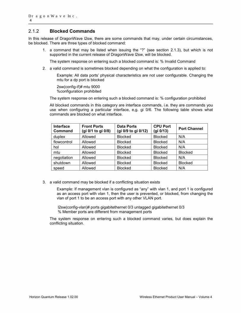
All blocked commands in this category are interface commands, i.e. they are commands you use when configuring a particular interface, e,g. gi 0/6. The following table shows what commands are blocked on what interface.
Interface Command
Front Ports (gi 0/1 to gi 0/8)
Data Ports (gi 0/9 to gi 0/12)
CPU Port (gi 0/13) Port Channel
duplex Allowed Blocked Blocked N/A flowcontrol Allowed Blocked Blocked N/A hol Allowed Blocked Blocked N/A mtu Allowed Blocked Blocked Blocked negotiation Allowed Blocked Blocked N/A shutdown Allowed Blocked Blocked Blocked speed Allowed Blocked Blocked N/A
3. a valid command may be blocked if a conflicting situation exists
Example: If management vlan is configured as “any” with vlan 1, and port 1 is configured as an access port with vlan 1, then the user is prevented, or blocked, from changing the vlan of port 1 to be an access port with any other VLAN port. l2sw(config-vlan)# ports gigabitethernet 0/3 untagged gigabitethernet 0/3 % Member ports are different from management ports
The system response on entering such a blocked command varies, but does explain the conflicting situation.

Layer 2 Switch Feature 5
Horizon Quantum Release 1.02.00 Wireless Ethernet Product User Manual – Volume 4
Context Sensitive Help 2.1.3DragonWave CLI framework offers context sensitive help; The user can type a question mark (?) anytime during a session to get help. The help can be invoked in several ways. It is not displayed as a whole and is available only for the specific token from where it is invoked.
Examples of possible scenarios are given below.
1. User keys in a character followed immediately by a question mark (?). This displays the current possible tokens without help string.
l2sw# sh?
show
2. User enters a keyword at the command prompt and enters a question mark (?) after hitting a space. This displays the next possible tokens along with the corresponding help string..
l2sw# show ?
debugging State of each debugging option
Some of the basic concepts implemented for the context sensitive help are:
1. The next possible tokens are listed only in the lexical order and not in the order as available in the syntax or command structure.
2. All possible tokens are listed along with the help string, even though the command is ambiguous. Any ambiguous command errors and value range errors are taken care of only during the execution of the command.
3. The help tokens provided within <> brackets denotes that the user should input values of specified format. For example, <string(32)> represents that the user should input a string of size varying from 1 to 32.
4. The help tokens provided within () brackets denotes that the user should input only the values represented. For example, (1-4094) represents that the user should input value within the mentioned range alone.
5. The format is directly provided as help token for some non-keyword such as MAC address. For example, aa:aa:aa:aa:aa:aa represents that a MAC address of this format should be provided.
6. Only the most commonly used format is provided as help token for some non keywords, but the command supports most of the valid formats.
7. The help token <CR> along with help string explaining the operation of the command is displayed, if the command can be executed at that point (errors are handled only during the execution).

DragonWave Inc. 6
Horizon Quantum Release 1.02.00 Wireless Ethernet Product User Manual – Volume 4
CLI command modes 2.1.4The following table format lists the different CLI command modes. Depending on the CLI mode, l2sw prompt will be specific.
Command Mode Access Method Prompt Exit method
Privileged EXEC This is the initial mode to start a session
l2sw#
To return from the Privileged EXEC mode to Quantum CLI, type in exit.
Global Configuration The Privileged EXEC mode command configure terminal is used to enter the Global Configuration mode
l2sw(config)#
To exit to the Privileged EXEC mode the end command is used.
Config-VLAN The Global configuration mode command vlan vlan-id is used to enter the Config-VLAN mode.
l2sw(config-vlan)#
To exit to the Global Configuration mode the exit command is used and to exit to the Privileged EXEC mode the end command is used.
Privileged EXEC Mode 2.1.5When in a Quantum CLI session, if the user enters the CLI command “ l2sw”, the user will have access to the layer 2 switch at a user level comparable to that which s/he has for the Quantum (admin, NOC or Super User). The Privileged EXEC mode prompt is “l2sw#”.
Global Configuration Mode 2.1.6Global Configuration commands apply to features that affect the system as a whole, rather to any specific interface.
Interface Configuration Mode 2.1.7To enter into Interface configuration mode from the Global Configuration mode, interface <interface-type><interface-id> command is used. To exit to the global configuration mode the exit command is used and to exit to the privileged EXEC mode the end command is used.
2.1.7.1. Physical Interface Mode
The Physical Interface mode is used to perform interface specific operations. To return to the global configuration mode the exit command is used.
2.1.7.2. VLAN Interface Mode
The VLAN Interface mode is used to perform L3-IPVLAN specific operations. To return to the global configuration mode the exit command is used.
Layer 2 Switch Feature 7
Horizon Quantum Release 1.02.00 Wireless Ethernet Product User Manual – Volume 4
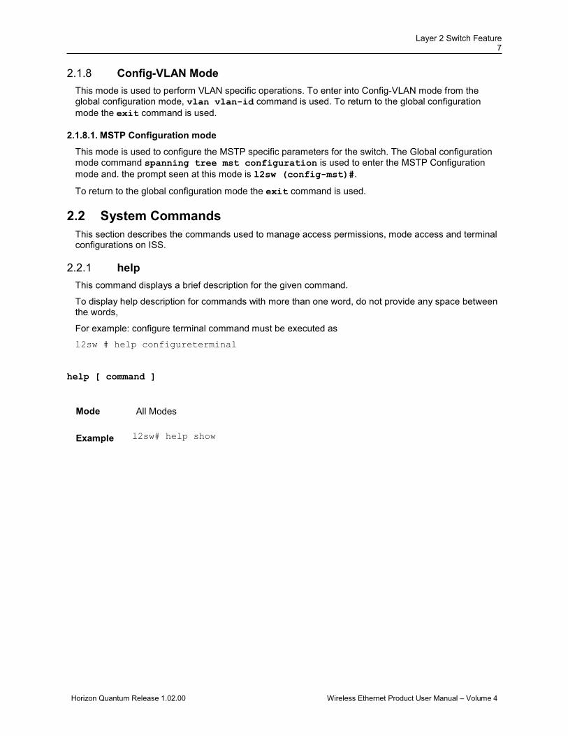
Config-VLAN Mode 2.1.8This mode is used to perform VLAN specific operations. To enter into Config-VLAN mode from the global configuration mode, vlan vlan-id command is used. To return to the global configuration mode the exit command is used.
2.1.8.1. MSTP Configuration mode
This mode is used to configure the MSTP specific parameters for the switch. The Global configuration mode command spanning tree mst configuration is used to enter the MSTP Configuration mode and. the prompt seen at this mode is l2sw (config-mst)#.
To return to the global configuration mode the exit command is used.
2.2 System Commands This section describes the commands used to manage access permissions, mode access and terminal configurations on ISS.
help 2.2.1This command displays a brief description for the given command.
To display help description for commands with more than one word, do not provide any space between the words,
For example: configure terminal command must be executed as
l2sw # help configureterminal
help [ command ]
Mode All Modes
Example l2sw# help show

DragonWave Inc. 8
Horizon Quantum Release 1.02.00 Wireless Ethernet Product User Manual – Volume 4
disable 2.2.2This command turns off privileged commands. The privilege level varies between 0 and 15.
disable [<0-15> Privilege level to go to]
Mode User EXEC Mode
Package Workgroup, Enterprise, Metro_E and Metro
Example l2sw # disable 1
The privilege level value should be lesser than the privilege level value given in the enable command
Related Command
• enable - Enters to privileged EXEC mode
configure terminal 2.2.3This command enters to Global Configuration Mode which allows the user to execute all the commands that supports global configuration mode.
configure terminal
Mode Privileged EXEC Mode
Example l2sw# configure terminal
Related Commands
• end - Exits from Configuration mode
• exit - Exits the current configuration mode
Layer 2 Switch Feature 9
Horizon Quantum Release 1.02.00 Wireless Ethernet Product User Manual – Volume 4
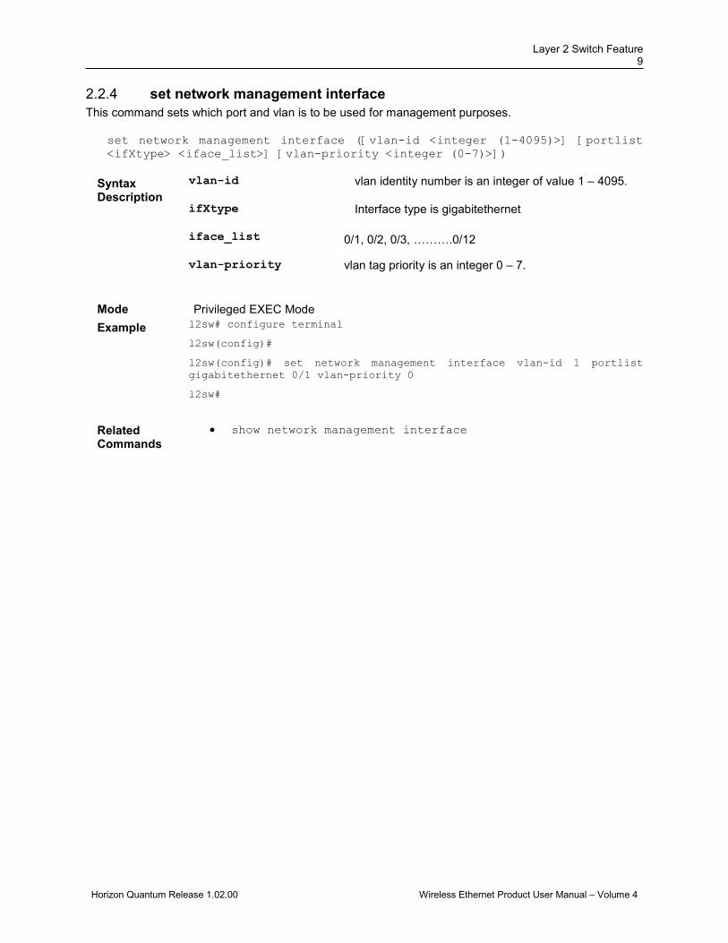
set network management interface 2.2.4This command sets which port and vlan is to be used for management purposes.
set network management interface ([vlan-id <integer (1-4095)>] [portlist <ifXtype> <iface_list>] [vlan-priority <integer (0-7)>])
Syntax Description
vlan-id - vlan identity number is an integer of value 1 – 4095.
ifXtype - Interface type is gigabitethernet
iface_list - 0/1, 0/2, 0/3, ……….0/12
vlan-priority vlan tag priority is an integer 0 – 7.
Mode Privileged EXEC Mode Example l2sw# configure terminal
l2sw(config)#
l2sw(config)# set network management interface vlan-id 1 portlist gigabitethernet 0/1 vlan-priority 0
l2sw#
Related Commands
• show network management interface

DragonWave Inc. 10
Horizon Quantum Release 1.02.00 Wireless Ethernet Product User Manual – Volume 4
configure terminal 2.2.5This command enters the configuration mode.
This command is a complete standardized implementation of the existing command and operates similar to that of the command configure terminal
Mode Privileged EXEC Mode
Example l2sw # configure terminal
Related Command
• end - Exits from Configuration mode
• exit - Exits the current configuration mode to the next highest configuration mode
end 2.2.6This command exits from the current mode to the Privileged EXEC mode
end
Mode All modes
Example l2sw# end
Related Command
• exit - Exits the current configuration mode
exit 2.2.7This command exits from the current configuration mode.
exit
Mode All modes
Example l2sw# exit
Related Command
• end - Exits from Configuration mode
Layer 2 Switch Feature 11
Horizon Quantum Release 1.02.00 Wireless Ethernet Product User Manual – Volume 4
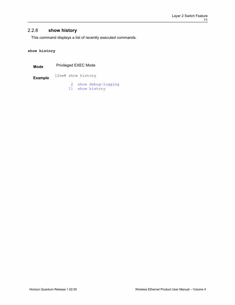
show history 2.2.8This command displays a list of recently executed commands.
show history
Mode Privileged EXEC Mode
Example l2sw# show history
2 show debug-logging 11 show history

DragonWave Inc. 12
Horizon Quantum Release 1.02.00 Wireless Ethernet Product User Manual – Volume 4
2.3 System Features DragonWave l2sw offers a rich set of system features to a user, such as duplex / negotiation support, and many other capabilities. Some features have special hardware requirements and others have special design considerations.
switchport 2.3.1This command configures the port as switch port. The no form of the command resets the port as router port.
• Only switch port related commands are made available for the interface, when the port is configured as switch port.
• Only router port related commands are made available for the interface, when the port is configured as router port. switchport
no switchport
Mode Interface Configuration Mode
Package Workgroup, Enterprise, Metro_E and Metro
Defaults switchport
Example l2sw(config-if)# switchport
The interface should be shutdown before executing this command.
Related Commands
• release - Releases, on the specified interface, the DHCP lease obtained for an IP address from a DHCP server.
• renew - Renews the DHCP lease for the interface specified. • ip dhcp relay circuit-id – Configures circuit ID value for an interface. • ip dhcp relay remote-id – Configures remote ID value for an interface. • show ip interface - Displays the IP interface configuration for all interfaces
available in the switch. • switchport filtering-utility-criteria - Creates filtering utility criteria
for the port. • switchport pvid - Configures the PVID on the specified port. • switchport acceptable-frame-type - Configures the type of VLAN
dependant BPDU frames such as GMRP BPDU, that the port should accept during the VLAN membership configuration.
• switchport ingress-filter - Enables ingress filtering feature on the port. • switchport map protocols-group - Maps the configured protocol group to
a particular VLAN ID for an interface. • switchport priority default - Configures the default ingress user priority
for a port. • switchport mode - Configures the mode of operation for a switch port. • switchport protected - Enables switchport protection feature for a port.

Layer 2 Switch Feature 13
Horizon Quantum Release 1.02.00 Wireless Ethernet Product User Manual – Volume 4
interface-configuration and deletion 2.3.2This command allows you to select an interface to configure.
interface {port-channel <integer (1-65535)> | tunnel <integer (0-128)> | <iftype> <ifnum> }
no interface {port-channel <integer (1-65535)> | tunnel <integer (0-128)> | <iftype> <ifnum> }
Syntax Description
port-channel<integer (1-65535)>
- Configures the port to be used by the host to configure the router. This value ranges between 1 and 65535.
The port channel identifier can be created or port channel related configuration can be done, only if the LA feature is enabled in the switch.
tunnel<integer (0-128)> - Configures the tunnel. This value ranges between 0
and 128. <iftype>
- Configures the specified type of interface. The interface
can be: • fastethernet – Officially referred to as 100BASE-T
standard. This is a version of LAN standard architecture that supports data transfer upto 100 Megabits per second.
• gigabitethernet – A version of LAN standard architecture that supports data transfer upto 1 Gigabit per second.
• extreme-ethernet – A version of Ethernet that supports data transfer upto 10 Gigabits per second. This Ethernet supports only full duplex links.
• i-lan / internal-lan – Internal LAN created on a bridge per IEEE 802.1ap.
• port-channel – Logical interface that represents an aggregator which contains several ports aggregated together.
DragonWave Inc. 14
Horizon Quantum Release 1.02.00 Wireless Ethernet Product User Manual – Volume 4
<ifnum> Configures the specified interface identifier. This is a
unique value that represents the specific interface. This value is a combination of slot number and port number separated by a slash, for interface type other than i-lan and port-channel. For example: 0/1 represents that the slot number is 0 and port number is 1. Only i-lan or port-channel ID is provided, for interface types i-lan and port-channel. For example: 1 represents i-lan and port-channel ID.
Example l2sw# config terminal
l2sw(config)# interface gigabitethernet 0/5
l2sw(config-if)#
negotiation 2.3.3
This command enables auto-negotiation on the interface.
The no form of the command disables auto-negotiation on the interface.
The port in which auto-negotiation is enabled, negotiates with the other end for port properties like speed, duplexity and so one. The normal port uses the port property values configured by the administrator.
negotiation
no negotiation
Mode Interface Configuration Mode
Example l2sw(config-if)# negotiation
Layer 2 Switch Feature 15
Horizon Quantum Release 1.02.00 Wireless Ethernet Product User Manual – Volume 4
speed 2.3.4This command sets the speed of the interface. The no form of the command sets the speed of the interface to its default value.
speed { 10 | 100 | 1000 | 10000 | auto | nonegotiate}
no speed
Syntax Description
10
- Port runs at 10Mbps
100
- Port runs at 100Mbps
1000
- Port runs at 1000Mbps
10000
- Port runs at 10000Mbps
auto
- Port automatically configures it’s speed based on the
peer switch. The switch negotiates with the device at the other end of the link for the speed setting and then forces the speed setting to the negotiated value.
nonegotiate
- Disable negotiation on the ports.
This feature has been included to adhere to the Industry Standard CLI syntax. This feature is currently not supported.
Mode Interface Configuration Mode
Defaults auto
Example l2sw(config-if)# speed 100
• The Gigabit Ethernet port speed can be configured to 10, 100, or 1000 Mbps
• This command cannot be executed to manually set values, if the port is automatically negotiating the link parameters with its peer. In that case, use the command no-negotiation to disable auto-negotiation feature.
Related Commands
• no negotiation - Disables auto-negotiation on the interface.
• duplex - Configures the duplex operation

DragonWave Inc. 16
Horizon Quantum Release 1.02.00 Wireless Ethernet Product User Manual – Volume 4
hol blocking prevention 2.3.5This command enables the Head-Of-Line blocking prevention on the interface and the no form of the command disables the same.
hol blocking prevention
no hol blocking prevention
Mode Interface Configuration Mode
Defaults Enabled
Example l2sw(config-if)#hol blocking prevention
description 2.3.6This command allows you to give a Description to an interface.
description <string(127)>
Mode Interface Configuration Mode
Defaults null
Example l2sw(config)# int gig 0/1
l2sw(config-if)# description “this is interface one”
To verify the above configuration:
l2sw# show interface description
no description 2.3.7 This command deletes a previously assigned description of the interface.
Mode Interface Configuration Mode
Defaults null
Example l2sw(config)# int gig 0/1
l2sw(config-if)# no description

Layer 2 Switch Feature 17
Horizon Quantum Release 1.02.00 Wireless Ethernet Product User Manual – Volume 4
duplex 2.3.8
This command configures the duplex operation.
The no form of the command configures the duplex operation to the default value.
duplex { full | half |auto}
no duplex
Syntax Description
full
- Port is in full-duplex mode, that is data simultaneously
communicates in both directions.
half
- Port is in half-duplex mode, that is data can
communicate in both directions, but only in one direction at a time.
auto
- Port is in auto mode.
This feature has been included to adhere to the Industry Standard CLI syntax. This feature is currently not supported.
Mode Interface Configuration Mode
Defaults full
Example l2sw(config-if)# duplex half
• Applicability of this command depends on the device to which the switch is attached.
• This command cannot be executed to manually set values, if the port is automatically negotiating the link parameters with its peer. In that case, use the command no-negotiation to disable auto-negotiation feature.
Related Commands
• no negotiation - Disables auto-negotiation on the interface
• speed - Sets the speed of the interface
DragonWave Inc. 18
Horizon Quantum Release 1.02.00 Wireless Ethernet Product User Manual – Volume 4
mtu frame size 2.3.9This command configures the maximum transmission unit frame size for the interface. The value ranges between 90 and 9216.
This value defines the largest PDU that can be passed by the interface without any need for fragmentation. This value is shown to the higher interface sub-layer and should not include size of the encapsulation or header added by the interface. This value represents the IP MTU over the interface, if IP is operating over the interface.
mtu <frame-size(90-9216)>
Mode Interface Configuration Mode
Defaults 1500
Example l2sw (config-if)# mtu 900
• This configuration can be done, only if the interface is administratively down. • The MTU value should not be greater than 1522 for fastEthernet interface.
Related Commands
• show interfaces - Displays the interface status and configuration • show interface mtu - Displays the global maximum transmission unit • shutdown-physical/VLAN/port-channel/tunnel Interface – Enables
the physical interface / VLAN interface / port-channel interface / tunnel interface / OOB interface.
Layer 2 Switch Feature 19
Horizon Quantum Release 1.02.00 Wireless Ethernet Product User Manual – Volume 4
flowcontrol 2.3.10This command is used to set the send or receive flow-control value for an interface.
If flowcontrol send is on for a device and if it detects any congestion at its end, then it notifies the link partner or the remote device of the congestion by sending a pause frame.
If flowcontrol receive is on for the remote device and it receives a pause frame, then it stops sending any data packets. This prevents any loss of data packets during the congestion period.
PAUSE is a flow control mechanism that is implied on full duplex Ethernet link segments. The mechanism uses MAC control frames to carry the PAUSE commands.
flowcontrol { send | receive} { on | off | desired}
Syntax Description
send - Sets the interface to send flow control packets to a remote device
receive
- Sets the interface to receive flow control packets from a remote
device on
- If used with receive allows an interface to operate with the
attached device to send flow control packets
If used with send the interface sends flowcontrol packets to a remote device if the device supports it
off
- Turns-off the attached devices (when used with receive) or the
local ports (when used with send) ability to send flow-control packets to an interface or to a remote device respectively
desired - Allows a local port to operate with an attached device that is required to send flow control packets or that may send the control packets, when used with receive option.
Allows the local port to send administrative status to a remote device if the remote device supports it, when used with send option.
This feature has been included to adhere to the Industry Standard CLI syntax. This feature is currently not supported.
Mode Interface Configuration Mode
Package Workgroup, Enterprise, Metro_E and Metro
Defaults The default flow control for the interfaces are flowcontrol receive off flowcontrol send off
Example l2sw(config-if)# flowcontrol send on
Related Commands
• show interfaces - Displays the interface status and configuration
• show flow-control - Displays the flowcontrol information
DragonWave Inc. 20
Horizon Quantum Release 1.02.00 Wireless Ethernet Product User Manual – Volume 4
shutdown - physical/VLAN/port-channel/tunnel Interface 2.3.11This command disables a physical interface / VLAN interface / port-channel interface / tunnel interface / OOB interface. The no form of the command enables a physical interface / VLAN interface / port-channel interface / tunnel interface / OOB interface.
shutdown
no shutdown
Mode Interface Configuration Mode for physical interface / port-channel/tunnel interface/OOB Interface
VLAN Interface Mode for VLAN interface
Defaults The Physical Interfaces gi 0/1 and gi 0/2 are disabled and al other physical interfaces are enabled
The Port-channel interface is disabled
Example l2sw (config-if)# shutdown
• All functions on the specified interface are disabled by the shutdown command
Related Commands
• show spanning-tree - Summary, Blockedports, Pathcost, redundancy - Displays spanning tree related information available in the switch for the current STP enabled in the switch.
• show spanning-tree detail - Displays detailed spanning tree related information of the switch and all ports enabled in the switch.
• show spanning-tree active - Displays spanning tree related information available in the switch for the current STP enabled in the switch.
• show spanning-tree – layer 2 gateway port - Displays spanning tree information for all L2GPs enabled in the switch.
• show spanning-tree mst - CIST or specified mst Instance - Displays multiple spanning tree information for all MSTIs in the switch.
• show interfaces - Displays the interface status and configuration

Layer 2 Switch Feature 21
Horizon Quantum Release 1.02.00 Wireless Ethernet Product User Manual – Volume 4
debug interface 2.3.12This command sets the debug traces for all the interfaces. The no form of the command resets the configured debug traces.
debug interface [track] [enetpktdump] [ippktdump] [arppktdump] [trcerror] [os] [failall] [buffer] [all]
no debug interface [track] [enetpktdump] [ippktdump] [arppktdump] [trcerror] [os] [failall] [buffer] [all]
Syntax description
track - Generates debug messages for all track messages.
enetpktdump - Generates debug messages for ethernet packet dump messages.
ippktdump - Generates debug messages for IP protocol related packet dump messages.
arppktdump - Generates debug messages for address resolution protocol related packet dump messages.
trcerror - Generates debug messages for trace error messages.
os - Generates debug messages for for OS resources. For example, when there is a failure in mem pool creation / deletion, this trace level is used
failall - Generates debug messages for all failures including packet validation.
buffer - Generates debug messages for buffer trace levels where packet buffer is used.i.e in cases wher packet is enqueued
all - Generates debug messages for all kinds of traces.
Mode Priviliege EXEC mode
Example l2sw# debug interface track

DragonWave Inc. 22
Horizon Quantum Release 1.02.00 Wireless Ethernet Product User Manual – Volume 4
clear counters 2.3.13This command clears the interface counters.
This command is a standardized implementation of the existing command and operates similar to that of the command clear interfaces - counters.
clear counters [ <interface-type> <interface-id> ]
Syntax Description
interface-type
- Type of interface. This can be:
• FastEthernet
• GigabitEthernet interface-id
- Physical interface ID including slot and port number.
Mode Privileged EXEC Mode
Example l2sw# clear counters
Related Command
• show interfaces counters - Displays the interface statistics for each port.
• show interfaces - Displays the interface status and configuration
Layer 2 Switch Feature 23
Horizon Quantum Release 1.02.00 Wireless Ethernet Product User Manual – Volume 4
show interfaces 2.3.14This command displays the interface status and configuration.
show interfaces [{ [<interface-type> <interface-id>] [{ description | storm-control | flowcontrol | capabilities | status }] | { vlan <vlan-id(1-4094)> [{switch <switch-name>}]} | port-channel <port-channel-id (1-65535)> | tunnel <tunnel-id (0-128)>| private-vlan mapping}]
Syntax Description
<interface-type>
- Displays the interface status and configuration for the
specified type of interface. The interface can be: • gigabitethernet – A version of LAN standard
architecture that supports data transfer upto 1 Gigabit per second.
<interface-id>
- Displays the interface status and configuration for the
specified interface identifier. This is a unique value that represents the specific interface. This value is a combination of slot number and port number separated by a slash. For example: 0/1 represents that the slot number is 0 and port number is 1.
description
- Displays the admin status and protocol status for
the specified interface.
storm-control
- Displays the broadcast, multicast, and unicast storm
control suppression levels for the specified interface
flowcontrol
- Displays the flow control related statistics information for the specified interface.
capabilities
- Displays the interface type, interface speed, duplex
operation and flowcontrol status for the specified interface.
status
- Displays the status, duplex details, speed and
negotiation mode of the specified interface.
vlan<vlan-id(1-4094)>
- Displays the interface status and configuration for the specified VLAN ID. This is a unique value that represents the specific VLAN created. This value ranges between 1 and 4094.
DragonWave Inc. 24
Horizon Quantum Release 1.02.00 Wireless Ethernet Product User Manual – Volume 4
switch - Configures IP interface for the specified context.
This value represents unique name of the switch context. This value is a string whose maximum size is 32 This parameter is specific to multiple instance feature.
This feature has been included to adhere to the Industry Standard CLI syntax
port-channel<port-channel-id (1-65535)>
- Displays the interface status and configuration for the specified port-channel ID. This is a unique value that represents the specific port-channel created. This value ranges between 1 and 65535.
tunnel<tunnel-id (0-128)>
- Displays the interface status and configuration for the specified tunnel ID. This is a unique value that represents the specific tunnel created.. The value ranges between 0 and 128.
private-vlan mapping - Maps list of secondary Vlan to the primary vlan IVR
interface, so that both VLANs share the same primary VLAN
Mode Privileged EXEC Mode
Example l2sw# show interfaces gigabitethernet 0/1 Gi0/1 up, line protocol is up (connected) Bridge Port Type: Customer Bridge Port Hardware Address is 00:01:02:03:04:22 RARP Client is enabled MTU 1500 bytes, Full duplex, 100 Mbps, Auto-Negotiation HOL Block Prevention enabled. Invalid flowcontrol Mode Link Up/Down Trap is enabled Reception Counters Octets : 0 Unicast Packets : 0 Discarded Packets : 0 Error Packets : 0 Unknown Protocol : 0 Transmission Counters Octets : 8266 Unicast Packets : 0 Discarded Packets : 0 Error Packets : 0

Layer 2 Switch Feature 25
Horizon Quantum Release 1.02.00 Wireless Ethernet Product User Manual – Volume 4
l2sw# show interfaces description Interface Status Protocol Description ---------- --------- ---------------------- Gi0/1 up up Gi0/2 up up l2sw# show interfaces gigabitethernet 0/2 storm-control Gi0/2 DLF Storm Control : Disabled DLF Storm Control Limit : 0 Broadcast Storm Control : Enabled Broadcast Storm Control : 0 Multicast Storm Control : Enabled Multicast Storm Control : 0 l2sw# show interfaces gigabitethernet 0/2 flow-control Port Tx FlowControl Rx FlowControl Tx Pause Rx Pause HC TxPause HC R ---- -------------- ------------- -------- -------- ----------- ----- Gi0/2 off off 0 0 0 0 l2sw# show interfaces gigabitethernet 0/2 capabilities Gi0/2 Type : 10/100/1000 Base TX Speed : 10, 100, 1000, Auto Duplex : Half, Full FlowControl : Send, Receive l2sw# show interfaces gigabitethernet 0/2 status Port Status Duplex Speed Negotiation ---- ------ ------ ------ ------------ Gi0/2 connected Full 100 Mbps Auto l2sw# show interfaces port-channel 2 po2 up, line protocol is up (connected)
DragonWave Inc. 26
Horizon Quantum Release 1.02.00 Wireless Ethernet Product User Manual – Volume 4
Related Commands
• interface - Enters the interface mode and allows the user to execute all the commands that supports interface configuration mode.
• interface-configuration and deletion - Configures interface such as out of band management, port channel, tunnel and so on
• Snmp trap link-status - Enables trap generation on the interface.
• Storm-control - Sets storm control rate for broadcast, multicast and DLF packets
• flowcontrol - Enables flow-control
• show flow-control - Displays the flow-control information
• mac-addr - Configures MAC address for the interface.
• shutdown – physical/VLAN/port-channel/tunnel interface - Disables a physical interface / VLAN interface / port-channel interface / tunnel interface / OOB interface.

Layer 2 Switch Feature 27
Horizon Quantum Release 1.02.00 Wireless Ethernet Product User Manual – Volume 4
show interfaces - counters 2.3.15This command displays the interface statistics for each port.
show interfaces [{ <interface-type> <interface-id> | vlan < short(1-4094)> [switch <switch-name>] | tunnel <tunnel-id(0-128)>}] counters
Syntax Description
<interface-type>
- Displays the interface incoming and outgoing traffic
statistics for the specified type of interface. The interface can be: • fastethernet – Officially referred to as 100BASE-T
standard. This is a version of LAN standard architecture that supports data transfer upto 100 Megabits per second.
• gigabitethernet – A version of LAN standard architecture that supports data transfer upto 1 Gigabit per second.
• extreme-ethernet – A version of Ethernet that supports data transfer upto 10 Gigabits per second. This Ethernet supports only full duplex links.
• internal-lan – Internal LAN created on a bridge per IEEE 802.1ap.
• port-channel – Logical interface that represents an aggregator which contains several ports aggregated together.
<interface-id>
- Displays the interface incoming and outgoing traffic
statistics for the specified interface identifier. This is a unique value that represents the specific interface. This value is a combination of slot number and port number separated by a slash, for interface type other than internal-lan and port-channel. For example: 0/1 represents that the slot number is 0 and port number is 1. Only internal-lan or port-channel ID is provided, for interface types internal-lan and port-channel. For example: 1 represents internal-lan and port-channel ID.
vlan
- VLAN identifier. This value ranges between 1 and 4094. switch
- Name of the switch context. This value is a string of size 32.
This feature has been included to adhere to the Industry Standard CLI syntax
Mode Privileged EXEC Mode
Example l2sw# show interface counters Port InOctet InUcast InDiscard InErrs InHCOctet ---- ------- ------- --------- ------ --------- Gi0/1 215710 805 1730 1 0

DragonWave Inc. 28
Horizon Quantum Release 1.02.00 Wireless Ethernet Product User Manual – Volume 4
Gi0/2 0 0 0 0 0 Gi0/3 480494016 7507719 384586 0 0 Gi0/4 0 0 0 0 0 Gi0/5 2332132381 103548431 4985914 2 0 Gi0/6 0 0 0 0 0 Gi0/7 0 0 0 0 0 Gi0/8 0 0 0 0 0 Gi0/9 0 0 0 0 0 Gi0/10 0 0 0 0 0 Gi0/11 0 0 0 0 0 Gi0/12 0 0 0 0 0 Gi0/13 0 0 0 0 0 Gi0/14 455116678 7110937 7110935 1 0 Gi0/15 0 0 0 0 0 Gi0/16 0 0 0 0 0 Gi0/17 0 0 0 0 0 Gi0/18 0 0 0 0 0 Gi0/19 0 0 0 0 0 Gi0/20 0 0 0 0 0 Gi0/21 0 0 0 0 0 Gi0/22 0 0 0 0 0 Gi0/23 0 0 0 0 0 Gi0/24 0 0 0 0 0 vlan1 0 0 0 0 0 Port OutOctet OutUcast OutDiscard OutErrs OutHCOctet ---- -------- -------- ---------- ------- ---------- Gi0/1 516578823 8064080 0 0 0 Gi0/2 0 0 0 0 0 Gi0/3 1403553448 89039198 4486186 0 0 Gi0/4 0 0 0 0 0 Gi0/5 455902325 7123224 45 0 0 Gi0/6 0 0 0 0 0 Gi0/7 0 0 0 0 0 Gi0/8 0 0 0 0 0 Gi0/9 0 0 0 0 0 Gi0/10 0 0 0 0 0 Gi0/11 0 0 0 0 0 Gi0/12 0 0 0 0 0 Gi0/13 0 0 0 0 0 Gi0/14 2810 4 16645905 0 0 Gi0/15 0 0 0 0 0 Gi0/16 0 0 0 0 0 Gi0/17 0 0 0 0 0 Gi0/18 0 0 0 0 0 Gi0/19 0 0 0 0 0 Gi0/20 0 0 0 0 0 Gi0/21 0 0 0 0 0 Gi0/22 0 0 0 0 0 Gi0/23 0 0 0 0 0 Gi0/24 0 0 0 0 0 vlan1 78 1 0 0 0
Layer 2 Switch Feature 29
Horizon Quantum Release 1.02.00 Wireless Ethernet Product User Manual – Volume 4
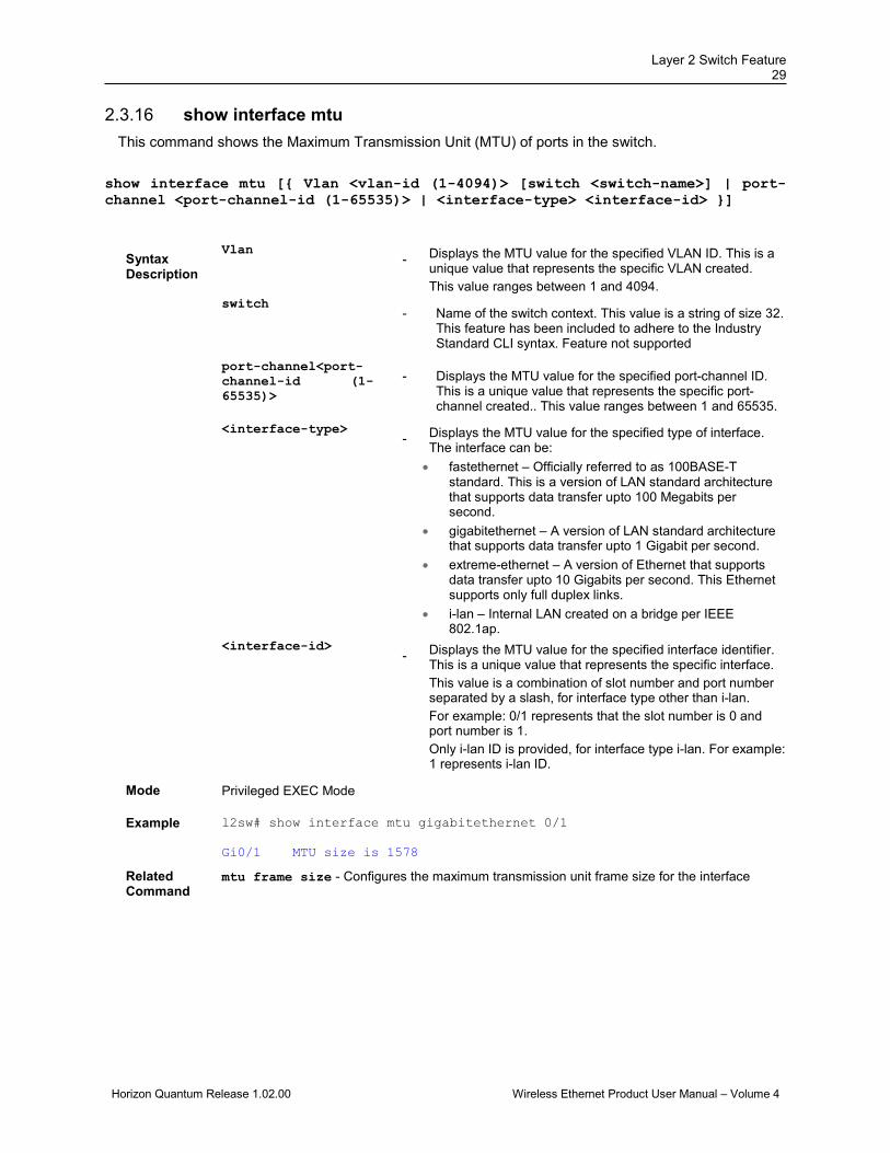
show interface mtu 2.3.16This command shows the Maximum Transmission Unit (MTU) of ports in the switch.
show interface mtu [{ Vlan <vlan-id (1-4094)> [switch <switch-name>] | port-channel <port-channel-id (1-65535)> | <interface-type> <interface-id> }]
Syntax Description
Vlan - Displays the MTU value for the specified VLAN ID. This is a
unique value that represents the specific VLAN created. This value ranges between 1 and 4094.
switch - Name of the switch context. This value is a string of size 32.
This feature has been included to adhere to the Industry Standard CLI syntax. Feature not supported
port-channel<port-channel-id (1-65535)>
- Displays the MTU value for the specified port-channel ID. This is a unique value that represents the specific port-channel created.. This value ranges between 1 and 65535.
<interface-type>
- Displays the MTU value for the specified type of interface.
The interface can be: • fastethernet – Officially referred to as 100BASE-T
standard. This is a version of LAN standard architecture that supports data transfer upto 100 Megabits per second.
• gigabitethernet – A version of LAN standard architecture that supports data transfer upto 1 Gigabit per second.
• extreme-ethernet – A version of Ethernet that supports data transfer upto 10 Gigabits per second. This Ethernet supports only full duplex links.
• i-lan – Internal LAN created on a bridge per IEEE 802.1ap.
<interface-id>
- Displays the MTU value for the specified interface identifier.
This is a unique value that represents the specific interface. This value is a combination of slot number and port number separated by a slash, for interface type other than i-lan. For example: 0/1 represents that the slot number is 0 and port number is 1. Only i-lan ID is provided, for interface type i-lan. For example: 1 represents i-lan ID.
Mode Privileged EXEC Mode
Example l2sw# show interface mtu gigabitethernet 0/1 Gi0/1 MTU size is 1578
Related Command
mtu frame size - Configures the maximum transmission unit frame size for the interface
DragonWave Inc. 30
Horizon Quantum Release 1.02.00 Wireless Ethernet Product User Manual – Volume 4
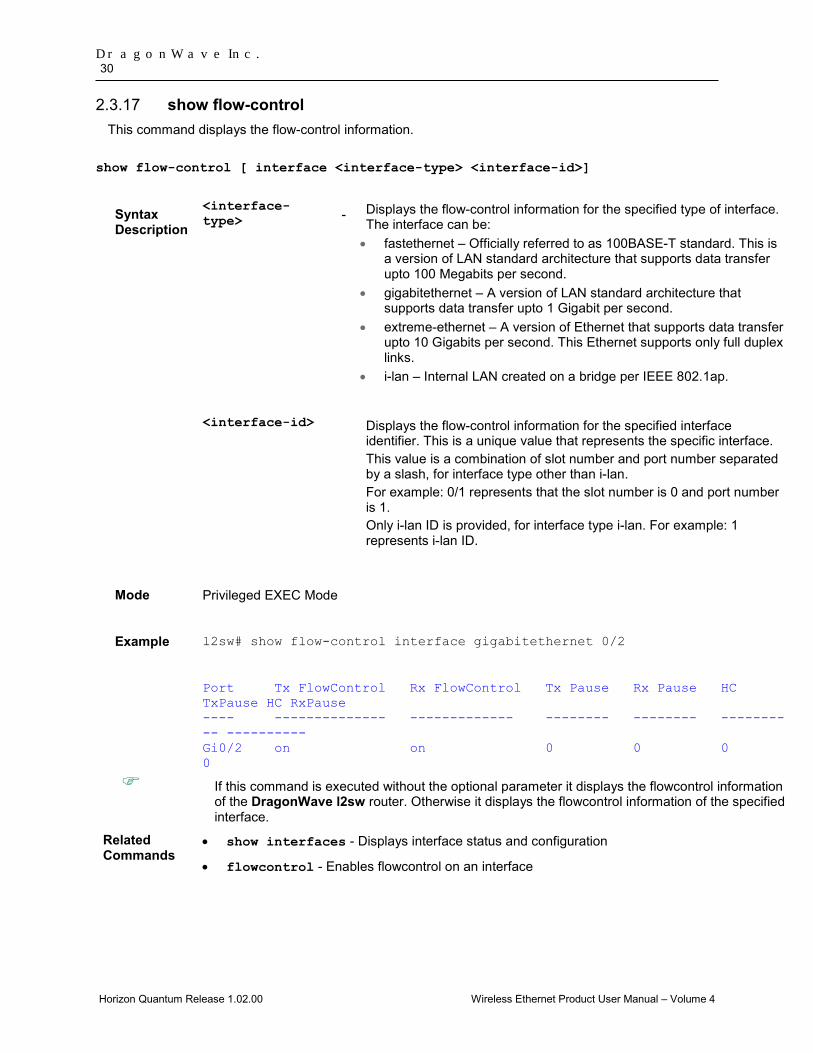
show flow-control 2.3.17This command displays the flow-control information.
show flow-control [ interface <interface-type> <interface-id>]
Syntax Description
<interface-type> - Displays the flow-control information for the specified type of interface.
The interface can be: • fastethernet – Officially referred to as 100BASE-T standard. This is
a version of LAN standard architecture that supports data transfer upto 100 Megabits per second.
• gigabitethernet – A version of LAN standard architecture that supports data transfer upto 1 Gigabit per second.
• extreme-ethernet – A version of Ethernet that supports data transfer upto 10 Gigabits per second. This Ethernet supports only full duplex links.
• i-lan – Internal LAN created on a bridge per IEEE 802.1ap.
<interface-id>
Displays the flow-control information for the specified interface identifier. This is a unique value that represents the specific interface. This value is a combination of slot number and port number separated by a slash, for interface type other than i-lan. For example: 0/1 represents that the slot number is 0 and port number is 1. Only i-lan ID is provided, for interface type i-lan. For example: 1 represents i-lan ID.
Mode Privileged EXEC Mode
Example l2sw# show flow-control interface gigabitethernet 0/2
Port Tx FlowControl Rx FlowControl Tx Pause Rx Pause HC TxPause HC RxPause ---- -------------- ------------- -------- -------- ---------- ---------- Gi0/2 on on 0 0 0 0
If this command is executed without the optional parameter it displays the flowcontrol information of the DragonWave l2sw router. Otherwise it displays the flowcontrol information of the specified interface.
Related Commands
• show interfaces - Displays interface status and configuration
• flowcontrol - Enables flowcontrol on an interface
Layer 2 Switch Feature 31
Horizon Quantum Release 1.02.00 Wireless Ethernet Product User Manual – Volume 4
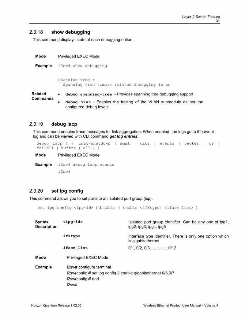
show debugging 2.3.18This command displays state of each debugging option.
Mode Privileged EXEC Mode
Example l2sw# show debugging
Spanning Tree : Spanning tree timers related debugging is on
Related Commands
• debug spanning-tree - Provides spanning tree debugging support
• debug vlan - Enables the tracing of the VLAN submodule as per the configured debug levels.
debug lacp 2.3.19This command enables trace messages for link aggregation. When enabled, the logs go to the event log and can be viewed with CLI command get log entries.
debug lacp [ { init-shutdown | mgmt | data | events | packet | os | failall | buffer | all } ]
Mode Privileged EXEC Mode
Example l2sw# debug lacp events
l2sw#
set ipg config 2.3.20This command allows you to set ports to an isolated port group (isp).
set ipg config <ipg-id> {disable | enable <ifXtype> <iface_list> }
Syntax Description
<ipg-id> Isolated port group identifier. Can be any one of ipg1, ipg2, ipg3, ipg4, ipg5
ifXtype Interface type identifier. There is only one option which is gigabitethernet
iface_list 0/1, 0/2, 0/3…………..0/12
Mode Privileged EXEC Mode
Example l2sw# configure terminal l2sw(config)# set ipg config 2 enable gigabitethernet 0/6,0/7 l2sw(config)# end l2sw#
DragonWave Inc. 32
Horizon Quantum Release 1.02.00 Wireless Ethernet Product User Manual – Volume 4
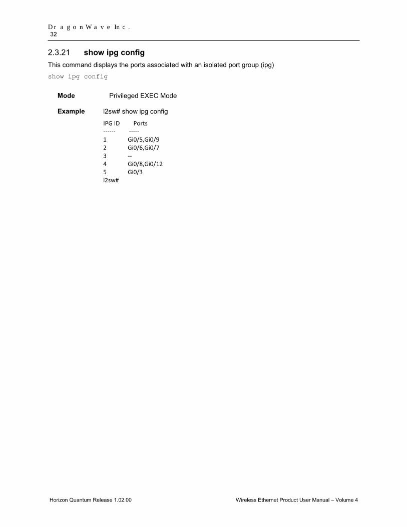
show ipg config 2.3.21This command displays the ports associated with an isolated port group (ipg)
show ipg config
Mode Privileged EXEC Mode
Example l2sw# show ipg config
IPG ID Ports ------ ----- 1 Gi0/5,Gi0/9 2 Gi0/6,Gi0/7 3 -- 4 Gi0/8,Gi0/12 5 Gi0/3 l2sw#
Layer 2 Switch Feature 33
Horizon Quantum Release 1.02.00 Wireless Ethernet Product User Manual – Volume 4
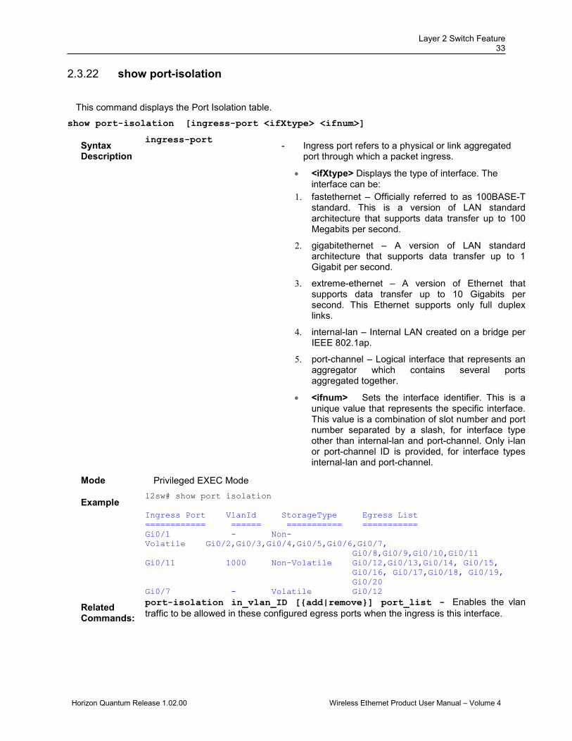
show port-isolation 2.3.22
This command displays the Port Isolation table. show port-isolation [ingress-port <ifXtype> <ifnum>]
Syntax Description
ingress-port - Ingress port refers to a physical or link aggregated
port through which a packet ingress.
• <ifXtype> Displays the type of interface. The interface can be:
1. fastethernet – Officially referred to as 100BASE-T standard. This is a version of LAN standard architecture that supports data transfer up to 100 Megabits per second.
2. gigabitethernet – A version of LAN standard architecture that supports data transfer up to 1 Gigabit per second.
3. extreme-ethernet – A version of Ethernet that supports data transfer up to 10 Gigabits per second. This Ethernet supports only full duplex links.
4. internal-lan – Internal LAN created on a bridge per IEEE 802.1ap.
5. port-channel – Logical interface that represents an aggregator which contains several ports aggregated together.
• <ifnum> Sets the interface identifier. This is a unique value that represents the specific interface. This value is a combination of slot number and port number separated by a slash, for interface type other than internal-lan and port-channel. Only i-lan or port-channel ID is provided, for interface types internal-lan and port-channel.
Mode Privileged EXEC Mode
Example l2sw# show port isolation Ingress Port VlanId StorageType Egress List ============ ====== =========== =========== Gi0/1 - Non-Volatile Gi0/2,Gi0/3,Gi0/4,Gi0/5,Gi0/6,Gi0/7, Gi0/8,Gi0/9,Gi0/10,Gi0/11 Gi0/11 1000 Non-Volatile Gi0/12,Gi0/13,Gi0/14, Gi0/15, Gi0/16, Gi0/17,Gi0/18, Gi0/19, Gi0/20 Gi0/7 - Volatile Gi0/12
Related Commands:
port-isolation in_vlan_ID [{add|remove}] port_list - Enables the vlan traffic to be allowed in these configured egress ports when the ingress is this interface.
DragonWave Inc. 34
Horizon Quantum Release 1.02.00 Wireless Ethernet Product User Manual – Volume 4
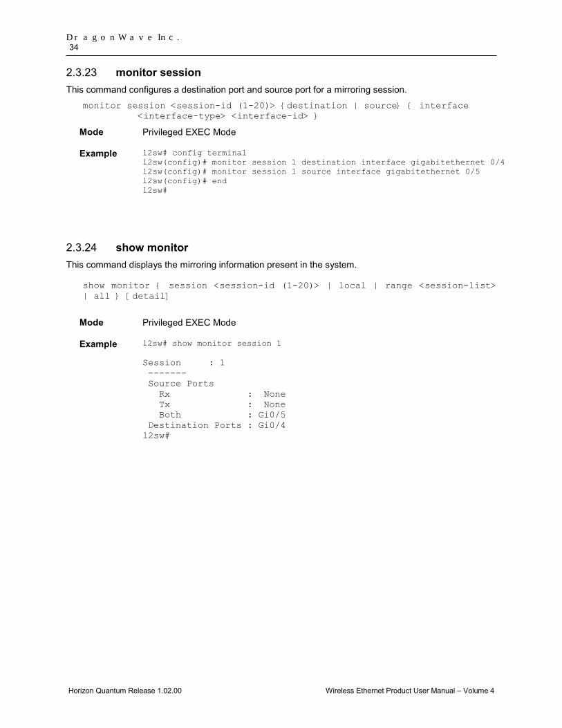
monitor session 2.3.23This command configures a destination port and source port for a mirroring session.
monitor session <session-id (1-20)> {destination | source} { interface <interface-type> <interface-id> }
Mode Privileged EXEC Mode
Example l2sw# config terminal l2sw(config)# monitor session 1 destination interface gigabitethernet 0/4 l2sw(config)# monitor session 1 source interface gigabitethernet 0/5 l2sw(config)# end l2sw#
show monitor 2.3.24This command displays the mirroring information present in the system.
show monitor { session <session-id (1-20)> | local | range <session-list> | all } [detail]
Mode Privileged EXEC Mode
Example l2sw# show monitor session 1 Session : 1 ------- Source Ports Rx : None Tx : None Both : Gi0/5 Destination Ports : Gi0/4 l2sw#

Layer 2 Switch Feature 35
Horizon Quantum Release 1.02.00 Wireless Ethernet Product User Manual – Volume 4
2.4 Spanning Tree Protocol (STP) STP is a link management protocol that provides path redundancy while preventing undesirable loops in the network that are created by multiple active paths between stations. To establish path redundancy, STP creates a tree that spans all of the switches in an extended network, forcing redundant paths into a standby or blocked state.
For an Ethernet network to function properly, only one active path should exist between two stations. Multiple active paths between stations in a bridged network can cause loops in which Ethernet frames can endlessly circulate. STP logically breaks such loops and prevents looping traffic from clogging the network. The dynamic control of the topology provides continued network operation in the presence of redundant or unintended looping paths.
The prompt for the global configuration mode is,
l2sw(config-switch)# spanning-tree mode rst
The STP functionality is realized in the network using one of the two following STPs:
• RSTP • MSTP
Note 1 - STP cannot be enabled on an Ethernet port that is not configured as part of the isolated port group IPG0.
RSTP 2.4.1DragonWave RSTP is an implementation of the IEEE 802.1D standard. It provides rapid recovery of connectivity following the failure of a bridge/bridge port or a LAN. It reduces the time to reconfigure the active topology of the network when physical topology or topology configuration parameters change. It provides increased availability of MAC service when there is a reconfiguration or failure of components in a bridged LAN. It can interoperate with legacy STP bridges without any change in the configuration.
MSTP 2.4.2DragonWave MSTP is an implementation of the IEEE 802.1s standard. It is used to configure spanning tree on per VLAN basis or multiple VLANs per spanning tree. It allows you to build several MST over VLAN trunks, and group or associate VLANs to spanning tree instances, so the topology of one instance is independent of the other instance. It provides multiple forwarding paths for data traffic and enables load balancing. It improves the overall network fault tolerance, as failure in one instance does not affect the other instances.
2.5 STP Commands Common for RSTP and MSTP
This section describes all spanning tree protocol related commands that are common for all kinds of STPs.
spanning-tree - Properties of an interface 2.5.1
This command configures the port related spanning tree information for all kinds of STPs.
The no form of this command resets the port related spanning tree information to its default value. The port related spanning tree information is changed to its default value even if the spanning tree mode is changed.
spanning-tree {cost <value(0-200000000)>|disable|link-type{point-to-point|shared}|portfast|port-priority <value(0-240)>}

DragonWave Inc. 36
Horizon Quantum Release 1.02.00 Wireless Ethernet Product User Manual – Volume 4
no spanning-tree {cost |disable|link-type|portfast|port-priority}
Syntax Description
cost - Configures the port’s path cost value that contributes to the path cost of paths containing this particular port. The paths’ path cost is used during calculation of shortest path to reach the root. The path cost represents the distance between the root port and designated port. This value ranges between 1 and 200000000. The configured path cost is used, even if the dynamic pathcost calculation feature or LAGG speed feature is enabled. This configuration is not supported for the spanning tree mode pvrst.
disable - Disables the spanning tree operation on the port. The port does not take part in the execution of spanning tree operation for preventing undesirable loops in the network.
link-type - Configures the link status of the LAN segment attached to the port. The options available are:
1. point-to-point – The port is treated as if it is connected to a point-to-point link.
2. shared - The port is treated as if it is using a shared media connection.
portfast - Configures the portfast feature in the port. This feature
specifies that the port is connected to only one hosts and hence can rapidly transit to forwarding. This feature can cause temporary bridging loops, if hubs, concentrators, switches, bridges and so on are connected to this port. This feature takes effect only when the interface is shutdown.
port-priority - Configures the priority value assigned to the port. This value is used during port role selection process. This value ranges between 0 and 240. This value should be set in steps of 16, that is, you can set the value as 0, 16, 32, 48, and so on. This configuration is not supported for the spanning tree mode pvrst.
Mode Interface Configuration Mode (Physical Interface Mode)
Package Workgroup, Enterprise, Metro_E and Metro
Layer 2 Switch Feature 37
Horizon Quantum Release 1.02.00 Wireless Ethernet Product User Manual – Volume 4
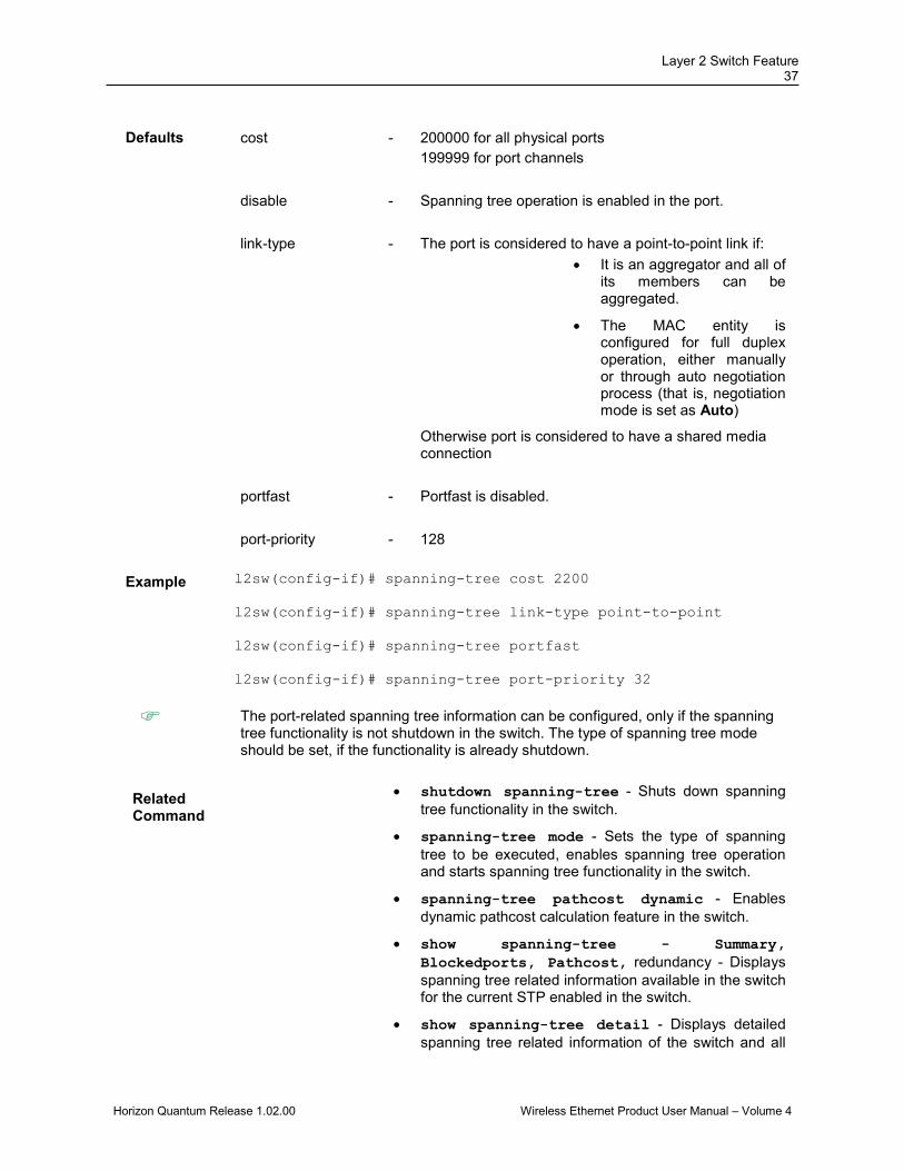
Defaults cost - 200000 for all physical ports
199999 for port channels
disable - Spanning tree operation is enabled in the port.
link-type - The port is considered to have a point-to-point link if: • It is an aggregator and all of
its members can be aggregated.
• The MAC entity is configured for full duplex operation, either manually or through auto negotiation process (that is, negotiation mode is set as Auto)
Otherwise port is considered to have a shared media connection
portfast - Portfast is disabled.
port-priority - 128
Example l2sw(config-if)# spanning-tree cost 2200 l2sw(config-if)# spanning-tree link-type point-to-point l2sw(config-if)# spanning-tree portfast l2sw(config-if)# spanning-tree port-priority 32
The port-related spanning tree information can be configured, only if the spanning tree functionality is not shutdown in the switch. The type of spanning tree mode should be set, if the functionality is already shutdown.
Related Command
• shutdown spanning-tree - Shuts down spanning tree functionality in the switch.
• spanning-tree mode - Sets the type of spanning tree to be executed, enables spanning tree operation and starts spanning tree functionality in the switch.
• spanning-tree pathcost dynamic - Enables dynamic pathcost calculation feature in the switch.
• show spanning-tree - Summary, Blockedports, Pathcost, redundancy - Displays spanning tree related information available in the switch for the current STP enabled in the switch.
• show spanning-tree detail - Displays detailed spanning tree related information of the switch and all
DragonWave Inc. 38
Horizon Quantum Release 1.02.00 Wireless Ethernet Product User Manual – Volume 4
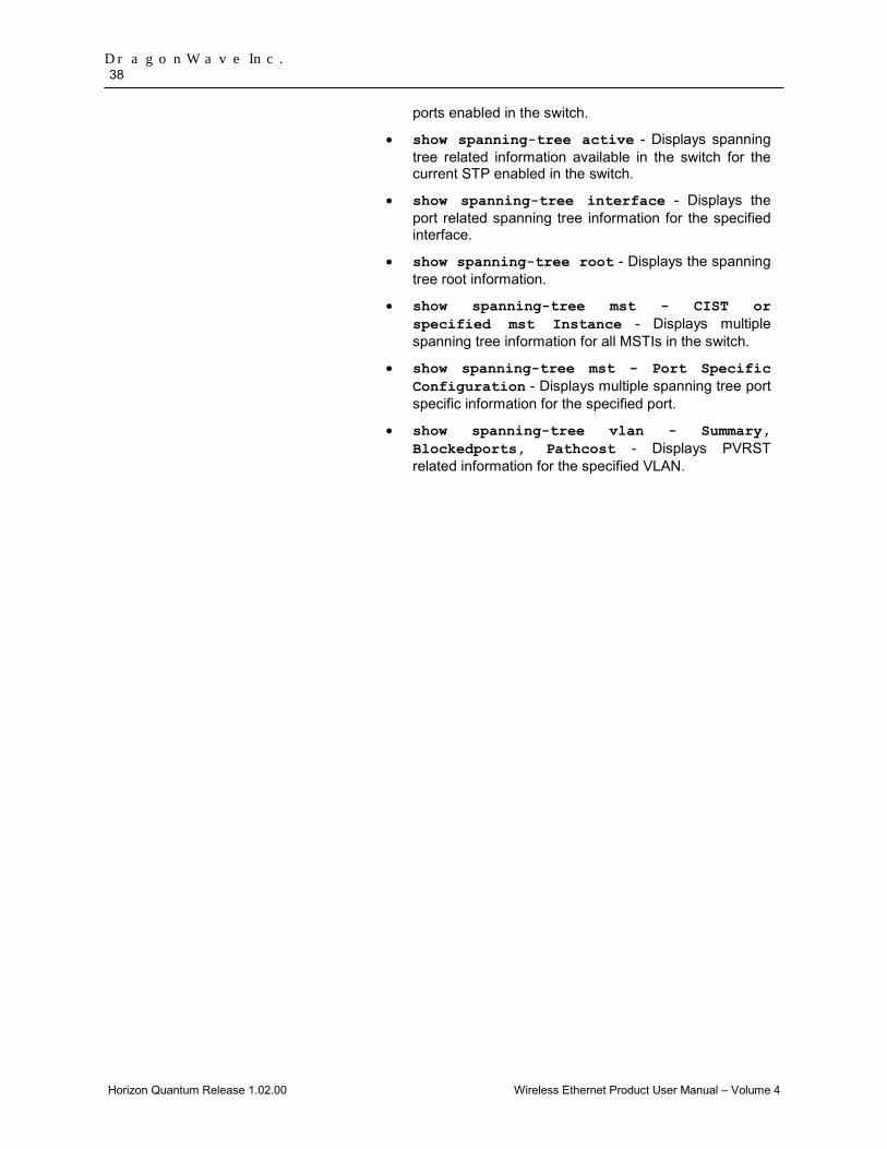
ports enabled in the switch.
• show spanning-tree active - Displays spanning tree related information available in the switch for the current STP enabled in the switch.
• show spanning-tree interface - Displays the port related spanning tree information for the specified interface.
• show spanning-tree root - Displays the spanning tree root information.
• show spanning-tree mst - CIST or specified mst Instance - Displays multiple spanning tree information for all MSTIs in the switch.
• show spanning-tree mst - Port Specific Configuration - Displays multiple spanning tree port specific information for the specified port.
• show spanning-tree vlan - Summary, Blockedports, Pathcost - Displays PVRST related information for the specified VLAN.

Layer 2 Switch Feature 39
Horizon Quantum Release 1.02.00 Wireless Ethernet Product User Manual – Volume 4
shutdown spanning-tree 2.5.2This command shuts down spanning tree functionality in the switch. The switch does not execute any kind of STP to form a loop free topology in the Ethernet network and operates with the existing topology structure.
shutdown spanning-tree
Mode Global Configuration Mode
Defaults Spanning tree MSTP is started and enabled in the switch.
Example l2sw(config)# shutdown spanning-tree
Related Commands
• spanning-tree - Enables the spanning tree operation in the switch for the selected spanning tree mode.
• spanning-tree mode - Sets the type of spanning tree to be executed, enables spanning tree operation and starts spanning tree functionality in the switch.
• spanning-tree compatibility - Sets the STP compatibility version in the switch for all ports.
• spanning-tree timers - Sets the spanning tree timers such as hello time, that are used for controlling the transmission of BPDUs during the computation of loop free topology.
• spanning-tree transmit hold-count - Sets the transmit hold-count value for the switch.
• clear spanning-tree counters - Deletes all bridge and port level spanning tree statistics information.
• spanning-tree pathcost dynamic - Enables dynamic pathcost calculation feature in the switch.
• spanning-tree priority - Configures the priority value that is assigned to the switch.
• spanning-tree auto-edge - Enables automatic detection of Edge port parameter of an interface.
• spanning-tree - Properties of an interface - Configures the port related spanning tree information for all kinds of STPs.
• spanning-tree restricted-role - Enables the restricted role feature for a port.
• spanning-tree restricted-tcn - Enables the topology change guard / restricted TCN feature on a port.
• spanning-tree layer2-gateway-port - Configures a port to operate as a L2GP.
• spanning-tree bpdu-receive - Configures the processing status of the BPDUs received in a port.
• spanning-tree bpdu-transmit - Configures the BPDU transmission status of a port.
• spanning-tree loop-guard - Enables the loop guard

DragonWave Inc. 40
Horizon Quantum Release 1.02.00 Wireless Ethernet Product User Manual – Volume 4
feature in a port.
• spanning-tree – Pseudoroot configuration - Configures the pseudoroot related information for a port set as L2GP.
• show spanning-tree - Summary, Blockedports, Pathcost, redundancy - Displays spanning tree related information available in the switch for the current STP enabled in the switch.
• show spanning-tree detail - Displays detailed spanning tree related information of the switch and all ports enabled in the switch.
• show spanning-tree active - Displays spanning tree related information available in the switch for the current STP enabled in the switch.
• show spanning-tree interface - Displays the port related spanning tree information for the specified interface.
• show spanning-tree root - Displays the spanning tree root information.
• show spanning-tree bridge - Displays the spanning tree bridge information.
• show spanning-tree – layer 2 gateway port - Displays spanning tree information for all L2GPs enabled in the switch.
• spanning-tree mst max-hops - Configures the maximum number of hops permitted in the MST.
• spanning-tree mst configuration - Enters into MST configuration mode, where instance specific and MST region configuration can be done.
• spanning-tree mst max-instance - Configures the maximum number of active MSTIs that can be created.
• spanning-tree mst- Properties of an interface for MSTP - Configures the port related spanning tree information for a specified MSTI.
• spanning-tree mst hello-time - Configures the hello time for an interface that is enabled.
• show spanning-tree mst - CIST or specified mst Instance - Displays multiple spanning tree information for all MSTIs in the switch.
• show spanning-tree mst configuration - Displays multiple spanning tree instance related information.
• show spanning-tree mst - Port Specific Configuration - Displays multiple spanning tree port specific information for the specified port.
• spanning-tree bpduguard - Configures the status of BPDU guard feature in an interface.
• spanning-tree guard - Configures the various PVRST guard features such as root guard, in a port.

Layer 2 Switch Feature 41
Horizon Quantum Release 1.02.00 Wireless Ethernet Product User Manual – Volume 4
spanning-tree 2.5.3
This command enables the spanning tree operation in the switch for the selected spanning tree mode.
The no form of this command disables the spanning tree operation in the switch. The spanning tree operation is automatically enabled in the switch, once the spanning tree mode is changed.
Spanning tree operation provides path redundancy while preventing undesirable loops in the network that are created by multiple active paths between stations. It logically breaks such loops and prevents looping traffic from clogging the network.
spanning-tree
no spanning-tree
Mode Global Configuration Mode
Defaults Spanning tree MSTP is started and enabled in the switch.
Example l2sw(config)#spanning-tree
The spanning tree operation can be enabled in the switch only if the spanning tree functionality is not shutdown in the switch. The type of spanning tree mode should be set, if the functionality is already shutdown.
Related Commands
• shutdown spanning-tree - Shuts down spanning tree functionality in the switch.
• spanning-tree mode - Sets the type of spanning tree to be executed, enables spanning tree operation and starts spanning tree functionality in the switch.
• show spanning-tree - Summary, Blockedports, Pathcost, redundancy - Displays spanning tree related information available in the switch for the current STP enabled in the switch.
• show spanning-tree detail - Displays detailed spanning tree related information of the switch and all ports enabled in the switch.
• show spanning-tree active - Displays spanning tree related information available in the switch for the current STP enabled in the switch.
• show spanning-tree interface - Displays the port related spanning tree information for the specified interface.
• show spanning-tree bridge - Displays the spanning tree bridge information.
• show spanning-tree mst - CIST or specified mst Instance - Displays multiple spanning tree information for all MSTIs in the switch.
• show spanning-tree mst - Port Specific Configuration - Displays multiple spanning tree port specific information for the specified port.

DragonWave Inc. 42
Horizon Quantum Release 1.02.00 Wireless Ethernet Product User Manual – Volume 4
spanning-tree mode 2.5.4
This command sets the type of spanning tree to be executed, enables spanning tree operation and starts spanning tree functionality in the switch. The current selected type of spanning tree is enabled and the existing spanning tree type is disabled in the switch.
spanning-tree mode {mst|rst}
Syntax Description
mst - Configures the switch to execute MSTP for preventing undesirable loops. MSTP configures spanning tree on per VLAN basis or multiple VLANs per spanning tree. The mode cannot be set as mst, if the base bridge mode is configured as transparent bridging.
rst - Configures the switch to execute RSTP for preventing undesirable loops. RSTP provides rapid recovery of connectivity following the failure of a bridge/bridge port or a LAN.
Mode Global Configuration Mode
Defaults mst
Example l2sw(config)#spanning-tree mode rst
Related Commands
• shutdown spanning-tree - Shuts down spanning tree functionality in the switch.
• spanning-tree - Enables the spanning tree operation in the switch for the selected spanning tree mode.
• spanning-tree compatibility - Sets the STP compatibility version in the switch for all ports.
• spanning-tree timers - Sets the spanning tree timers such as hello time, that are used for controlling the transmission of BPDUs during the computation of loop free topology.
• spanning-tree transmit hold-count - Sets the transmit hold-count value for the switch.
• clear spanning-tree counters - Deletes all bridge and port level spanning tree statistics information.
• spanning-tree pathcost dynamic - Enables dynamic pathcost calculation feature in the switch.
• spanning-tree priority - Configures the priority value that is assigned to the switch.
• spanning-tree auto-edge - Enables automatic detection of Edge port parameter of an interface.
• spanning-tree - Properties of an interface -
Layer 2 Switch Feature 43
Horizon Quantum Release 1.02.00 Wireless Ethernet Product User Manual – Volume 4
Configures the port related spanning tree information for all kinds of STPs.
• spanning-tree loop-guard - Enables the loop guard feature in a port.
• show spanning-tree - Summary, Blockedports, Pathcost, redundancy - Displays spanning tree related information available in the switch for the current STP enabled in the switch.
• show spanning-tree detail - Displays detailed spanning tree related information of the switch and all ports enabled in the switch.
• show spanning-tree active - Displays spanning tree related information available in the switch for the current STP enabled in the switch.
• show spanning-tree interface - Displays the port related spanning tree information for the specified interface.
• show spanning-tree root - Displays the spanning tree root information.
• show spanning-tree bridge - Displays the spanning tree bridge information.
• show spanning-tree – layer 2 gateway port - Displays spanning tree information for all L2GPs enabled in the switch.
• spanning-tree mst max-hops - Configures the maximum number of hops permitted in the MST.
• spanning-tree mst max-instance - Configures the maximum number of active MSTIs that can be created.
• spanning-tree mst configuration - Enters into MST configuration mode, where instance specific and MST region configuration can be done.
• spanning-tree mst- Properties of an interface for MSTP - Configures the port related spanning tree information for a specified MSTI.
• spanning-tree mst hello-time - Configures the hello time for an interface that is enabled.
• show spanning-tree mst - CIST or specified mst Instance - Displays multiple spanning tree information for all MSTIs in the switch.
• show spanning-tree mst configuration - Displays multiple spanning tree instance related information.
• show spanning-tree mst - Port Specific Configuration - Displays multiple spanning tree port specific information for the specified port.

DragonWave Inc. 44
Horizon Quantum Release 1.02.00 Wireless Ethernet Product User Manual – Volume 4
spanning-tree compatibility 2.5.5
This command sets the STP compatibility version in the switch for all ports.
The no form of this command sets the STP compatibility version to its default value. The STP compatibility version is changed to its default value even if the spanning tree mode is changed.
The compatibility version allows the switch to temporarily operate (that is, till this configuration is reset manually) in other STP version even though the spanning tree mode is set as some other version. This configuration is useful during cases where spanning tree mode itself is not required to be changed.
spanning-tree compatibility {stp|rst|mst}
no spanning-tree compatibility
Syntax Description
stp - Configures the switch to execute spanning tree operation as specified in IEEE 802.1D.
rst - Configures the switch to execute spanning tree operation as specified in IEEE 802.1w.
mst - Configures the switch to execute spanning tree operation as specified in IEEE 802.1s. The STP compatibility version cannot be set as mst, if the spanning tree mode is set as rst.
Mode Global Configuration Mode
Defaults • If STP mode is set as mst, then spanning tree compatibility is set as mst.
• If STP mode is set as rst, then spanning tree compatibility is set as rst.
Example l2sw(config)#spanning-tree compatibility stp
• The STP compatibility version can be configured in the switch, only if the spanning tree functionality is not shutdown in the switch. The type of spanning tree mode should be set, if the functionality is already shutdown.
• The STP compatibility version does not change the operation of the switch whose spanning tree mode is set as PVRST.
Related Commands
• shutdown spanning-tree - Shuts down spanning tree functionality in the switch.
• spanning-tree mode - Sets the type of spanning tree to be executed, enables spanning tree operation and

Layer 2 Switch Feature 45
Horizon Quantum Release 1.02.00 Wireless Ethernet Product User Manual – Volume 4
starts spanning tree functionality in the switch.
• show spanning-tree - Summary, Blockedports, Pathcost, redundancy - Displays spanning tree related information available in the switch for the current STP enabled in the switch.
• show spanning-tree detail - Displays detailed spanning tree related information of the switch and all ports enabled in the switch.
• show spanning-tree active - Displays spanning tree related information available in the switch for the current STP enabled in the switch.
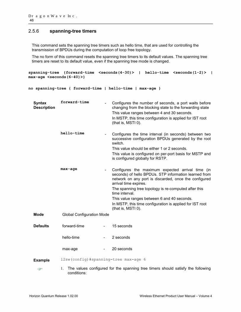
DragonWave Inc. 46
Horizon Quantum Release 1.02.00 Wireless Ethernet Product User Manual – Volume 4
spanning-tree timers 2.5.6
This command sets the spanning tree timers such as hello time, that are used for controlling the transmission of BPDUs during the computation of loop free topology.
The no form of this command resets the spanning tree timers to its default values. The spanning tree timers are reset to its default value, even if the spanning tree mode is changed.
spanning-tree {forward-time <seconds(4-30)> | hello-time <seconds(1-2)> | max-age <seconds(6-40)>}
no spanning-tree { forward-time | hello-time | max-age }
Syntax Description
forward-time - Configures the number of seconds, a port waits before changing from the blocking state to the forwarding state This value ranges between 4 and 30 seconds. In MSTP, this time configuration is applied for IST root (that is, MSTI 0).
hello-time - Configures the time interval (in seconds) between two successive configuration BPDUs generated by the root switch. This value should be either 1 or 2 seconds. This value is configured on per-port basis for MSTP and is configured globally for RSTP.
max-age - Configures the maximum expected arrival time (in seconds) of hello BPDUs. STP information learned from network on any port is discarded, once the configured arrival time expires. The spanning tree topology is re-computed after this time interval. This value ranges between 6 and 40 seconds. In MSTP, this time configuration is applied for IST root (that is, MSTI 0).
Mode Global Configuration Mode
Defaults forward-time - 15 seconds
hello-time - 2 seconds
max-age - 20 seconds
Example l2sw(config)#spanning-tree max-age 6
1. The values configured for the spanning tree timers should satisfy the following conditions:
Layer 2 Switch Feature 47
Horizon Quantum Release 1.02.00 Wireless Ethernet Product User Manual – Volume 4
• 2 * (forward-time - 1) >= max-age, and
• max-age >= 2 * (hello-time +1)
2. The STP timers can be configured in the switch, only if the spanning tree functionality is not shutdown in the switch. The type of spanning tree mode should be set, if the functionality is already shutdown.
3. This spanning tree timer’s configuration is not supported in PVRST mode.
Related Commands
• shutdown spanning-tree - Shuts down spanning tree functionality in the switch.
• spanning-tree mode - Sets the type of spanning tree to be executed, enables spanning tree operation and starts spanning tree functionality in the switch.
• show spanning-tree - Summary, Blockedports, Pathcost, redundancy - Displays spanning tree related information available in the switch for the current STP enabled in the switch.
• show spanning-tree detail - Displays detailed spanning tree related information of the switch and all ports enabled in the switch.
• show spanning-tree active - Displays spanning tree related information available in the switch for the current STP enabled in the switch.
• show spanning-tree interface detail - Displays detailed spanning tree related information for the specified port.
• show spanning-tree root - Displays the spanning tree root information.
• show spanning-tree bridge - Displays the spanning tree bridge information.
• show spanning-tree mst - CIST or specified mst Instance - Displays multiple spanning tree information for all MSTIs in the switch.
• show spanning-tree mst - Port Specific Configuration - Displays multiple spanning tree port specific information for the specified port.

DragonWave Inc. 48
Horizon Quantum Release 1.02.00 Wireless Ethernet Product User Manual – Volume 4
spanning-tree transmit hold-count 2.5.7
This command sets the transmit hold-count value for the switch.
The no form of this command sets the transmit hold-count to its default value. The transmit hold-count is changed to its default value even if the spanning tree mode is changed.
The transmit hold count value is a counter that is used to limit the maximum transmission rate of the switch and to avoid flooding. This value specifies the maximum number of packets that can be sent in a given hello time interval. This value ranges between 1 and 10.
spanning-tree transmit hold-count <value (1-10)>
no spanning-tree transmit hold-count
Mode Global Configuration Mode
Defaults 6, if the spanning tree mode is set as mst.
3, if the spanning tree mode is set as rst or pvrst.
Example l2sw(config)#spanning-tree transmit hold-count 5
• The transmit hold-count value can be configured in the switch, only if the spanning tree functionality is not shutdown in the switch. The type of spanning tree mode should be set, if the functionality is already shutdown.
• This transmit hold count value configuration is not supported in PVRST mode.
Related Commands
• shutdown spanning-tree - Shuts down spanning tree functionality in the switch.
• spanning-tree mode - Sets the type of spanning tree to be executed, enables spanning tree operation and starts spanning tree functionality in the switch.
• show spanning-tree detail - Displays detailed spanning tree related information of the switch and all ports enabled in the switch.
• show spanning-tree active detail - Displays detailed spanning tree related information of the switch and all ports enabled in the switch.
Layer 2 Switch Feature 49
Horizon Quantum Release 1.02.00 Wireless Ethernet Product User Manual – Volume 4
clear spanning-tree counters 2.5.8
This command deletes all bridge and port level spanning tree statistics information.
For RSTP, the information contains number of:
• Transitions to forwarding state
• RSTP BPDU count received / transmitted
• Config BPDU count received / transmitted
• TCN BPDU count received / transmitted
• Invalid BPDU count transmitted
• Port protocol migration count
For MSTP, the information contains number of:
• Port forward transitions
• Port received BPDUs
• Port transmitted BPDUs
• Port invalid BPDUs received
• Port protocol migration count
• BPDUs sent / received for each MSTI
clear spanning-tree counters
Mode Global Configuration Mode
Example l2sw(config)# clear spanning-tree counters
The statistics information can be deleted, only if the spanning tree functionality is not shutdown in the switch. The type of spanning tree mode should be set, if the functionality is already shutdown.
Related Commands
• shutdown spanning-tree - Shuts down spanning tree functionality in the switch.
• spanning-tree mode - Sets the type of spanning tree to be executed, enables spanning tree operation and starts spanning tree functionality in the switch.
• show spanning-tree detail - Displays detailed spanning tree related information of the switch and all ports enabled in the switch.
• show spanning-tree active detail - Displays detailed spanning tree related information of the switch and all ports enabled in the switch.
• show spanning-tree interface - Displays the port related spanning tree information for the specified
DragonWave Inc. 50
Horizon Quantum Release 1.02.00 Wireless Ethernet Product User Manual – Volume 4
interface.
• show spanning-tree mst - CIST or specified mst Instance - Displays multiple spanning tree information for all MSTIs in the switch.
• show spanning-tree mst - Port Specific Configuration - Displays multiple spanning tree port specific information for the specified port.
spanning-tree pathcost dynamic 2.5.9
This command enables dynamic pathcost calculation feature in the switch.
The no form of this command disables dynamic pathcost calculation feature in the switch. The dynamic pathcost calculation feature is disabled, even if the spanning tree mode is changed.
The path cost of the port / MSTI is dynamically calculated. This feature is applied only for the ports that are not shutdown during the execution of STP. The calculated path cost is not changed based on the operational status of the port / for a MSTI, once calculated. The manually assigned / already calculated path cost is used even if the dynamic pathcost calculation feature is enabled in the switch.
spanning-tree pathcost dynamic [lag-speed]
no spanning-tree pathcost dynamic [lag-speed]
Syntax description
lag-speed
- Calculates the path cost for change in speed of the port. This feature is used for LA ports whose speed changes due to addition or deletion of ports from the port channel. The manually assigned path cost is used even if the lag speed feature is enabled in the switch, if the path cost is assigned manually. The lag speed feature can be enabled, only after enabling the dynamic pathcost calculation feature.
Mode Global Configuration Mode
Defaults Dynamic pathcost calculation feature is disabled in the switch.
Example l2sw(config)# spanning-tree pathcost dynamic
The dynamic pathcost calculation feature can be configured in the switch, only if the spanning tree functionality is not shutdown in the switch. The type of spanning tree mode should be set, if the functionality is already shutdown.
Related Commands
• shutdown spanning-tree - Shuts down spanning tree functionality in the switch.
• spanning-tree mode - Sets the type of spanning tree

Layer 2 Switch Feature 51
Horizon Quantum Release 1.02.00 Wireless Ethernet Product User Manual – Volume 4
to be executed, enables spanning tree operation and starts spanning tree functionality in the switch.
• spanning-tree - Properties of an interface - Configures the port related spanning tree information for all kinds of STPs.
• show spanning-tree - Summary, Blockedports, Pathcost, redundancy – Displays spanning tree related information available in the switch for the current STP enabled in the switch.
• show spanning-tree detail - Displays detailed spanning tree related information of the switch and all ports enabled in the switch.
• show spanning-tree active - Displays spanning tree related information available in the switch for the current STP enabled in the switch.
• spanning-tree mst- Properties of an interface for MSTP - Configures the port related spanning tree information for a specified MSTI.
DragonWave Inc. 52
Horizon Quantum Release 1.02.00 Wireless Ethernet Product User Manual – Volume 4
spanning-tree priority 2.5.10
This command configures the priority value that is assigned to the switch.
The no form of this command resets the priority to its default value. The priority value is changed to its default value even if the spanning tree mode is changed.
In RSTP, this value is used during the election of root. In MSTP, this value is used during the election of CIST root, CIST regional root and IST root.
spanning-tree [mst <instance-id>] priority <value(0-61440)>
no spanning-tree [mst <instance-id(1-64)>] priority
Syntax Description
mst - Configures the ID of MSTP instance already created in the switch. This value ranges between 1 and 64. The special value 4094 can be used only in the switch that supports PBB-TE. This special value represents PTETID that identifies VID used by ESPs. This option is applicable, only if the spanning tree mode is set as mst.
priority - Configures the priority value for the switch and for the MSTI, in RSTP and MSTP respectively. This value ranges between 0 and 61440. The value should be set in steps of 4096, that is, you can set the value as 0, 4096, 8192, 12288 and so on.
Mode Global Configuration Mode
Defaults priority - 32768
Example l2sw(config)#spanning-tree priority 4096
• The priority value can be configured in the switch, only if the spanning tree functionality is not shutdown in the switch. The type of spanning tree mode should be set, if the functionality is already shutdown.
• This priority value configuration is not supported in PVRST mode.
Related Commands
• shutdown spanning-tree - Shuts down spanning tree functionality in the switch.
• spanning-tree mode - Sets the type of spanning tree to be executed, enables spanning tree operation and starts spanning tree functionality in the switch.
• show spanning-tree root - Displays the
Layer 2 Switch Feature 53
Horizon Quantum Release 1.02.00 Wireless Ethernet Product User Manual – Volume 4
spanning tree root information.
• show spanning-tree bridge - Displays the spanning tree bridge information.
• show spanning-tree - Summary, Blockedports, Pathcost, redundancy – Displays spanning tree related information available in the switch for the current STP enabled in the switch.
• show spanning-tree detail - Displays detailed spanning tree related information of the switch and all ports enabled in the switch.
• show spanning-tree active - Displays spanning tree related information available in the switch for the current STP enabled in the switch.
• instance - Creates an MST instance and maps it to VLANs.
• show spanning-tree mst - CIST or specified mst Instance - Displays multiple spanning tree information for all MSTIs in the switch.
• show spanning-tree mst - Port Specific Configuration - Displays multiple spanning tree port specific information for the specified port.
DragonWave Inc. 54
Horizon Quantum Release 1.02.00 Wireless Ethernet Product User Manual – Volume 4
spanning-tree auto-edge 2.5.11This command enables automatic detection of Edge port parameter of an interface.
The no form of this command disables automatic detection of Edge port parameter of an interface. The automatic detection of Edge port parameter is disabled, even if the spanning tree mode is changed.
Once automatic detection is enabled, the Edge port parameter is automatically detected and set. The port is set as edge port, if no BPDU is received on the port. The port is set as non-edge port, if any BPDU is received.
spanning-tree auto-edge
no spanning-tree auto-edge
Mode Interface Configuration Mode (Physical Interface Mode) Package Workgroup, Enterprise, Metro_E and Metro Defaults Automatic detection of Edge port parameter of an interface is enabled. Example l2sw(config-if)# spanning-tree auto-edge
The automatic detection of Edge port parameter can be configured in the switch, only if the spanning tree functionality is not shutdown in the switch. The type of spanning tree mode should be set, if the functionality is already shutdown.
Related Command
• shutdown spanning-tree - Shuts down spanning tree functionality in the switch.
• spanning-tree mode - Sets the type of spanning tree to be executed, enables spanning tree operation and starts spanning tree functionality in the switch.

Layer 2 Switch Feature 55
Horizon Quantum Release 1.02.00 Wireless Ethernet Product User Manual – Volume 4
spanning-tree layer2-gateway-port 2.5.12
This command configures a port to operate as a L2GP.
The no form of this command configures the port to operate as a normal port. The port operates as normal port, even if the spanning tree mode is changed.
L2GP operates similar to that of the normal port operation but pretends to continuously receive BPDUs when admin state of the port is Up.
spanning-tree layer2-gateway-port
no spanning-tree layer2-gateway-port
Mode Interface Configuration mode (Physical Interface Mode)
Package Workgroup, Enterprise Metro_E and Metro
Defaults The port operates as a normal port.
Example l2sw(config-if)# spanning-tree layer2-gateway-port
• The port can be configured as L2GP, only if the BPDU transmit status, restricted role feature and restricted TCN feature of the port are disabled.
• The PIP or CBP ports cannot be set as L2GP.
• Ports with SISP enabled interfaces cannot be set as L2GP.
• The port state of the L2GP is always set as discarding.
• The topology change guard / restricted TCN feature can be configured, only if the spanning tree functionality is not shutdown in the switch. The type of spanning tree mode should be set, if the functionality is already shutdown.
Related Commands
• shutdown spanning-tree - Shuts down spanning tree functionality in the switch.
• spanning-tree mode - Sets the type of spanning tree to be executed, enables spanning tree operation and starts spanning tree functionality in the switch.
• spanning-tree restricted-role - Enables the restricted role feature for a port.
• spanning-tree restricted-tcn - Enables the topology change guard / restricted TCN feature on a port.
• spanning-tree bpdu-transmit - Configures the BPDU transmission status of a port.

DragonWave Inc. 56
Horizon Quantum Release 1.02.00 Wireless Ethernet Product User Manual – Volume 4
• show spanning-tree - Summary, Blockedports, Pathcost, redundancy - Displays spanning tree related information available in the switch for the current STP enabled in the switch.
• show spanning-tree detail – Displays detailed spanning tree related information of the switch and all ports enabled in the switch.
• show spanning-tree active detail - Displays detailed spanning tree related information of the switch and all ports enabled in the switch.
• show spanning-tree interface - Displays the port related spanning tree information for the specified interface.
• show spanning-tree – layer 2 gateway port - Displays spanning tree information for all L2GPs enabled in the switch.
• show spanning-tree mst - CIST or specified mst Instance - Displays multiple spanning tree information for all MSTIs in the switch.
• show spanning-tree mst - Port Specific Configuration - Displays multiple spanning tree port specific information for the specified port.
• show spanning-tree vlan - Summary, Blockedports, Pathcost - Displays PVRST related information for the specified VLAN.
• show spanning-tree vlan - interface - Displays interface specific PVRST information for the specified VLAN.
•

Layer 2 Switch Feature 57
Horizon Quantum Release 1.02.00 Wireless Ethernet Product User Manual – Volume 4
spanning-tree bpdu-receive 2.5.13
This command configures the processing status of the BPDUs received in a port. BPDUs are used to carry bridge related information that is used during spanning tree operation.
The processing status is reset to its default value, once the spanning tree mode is changed.
spanning-tree bpdu-receive {enabled | disabled}
Syntax Description
enabled - Allows normal processing of BPDUs received on the port.
disabled - Discards the BPDUs received on the port.
Mode Interface configuration mode (Physical Interface Mode)
Package Workgroup, Enterprise Metro_E and Metro
Defaults enabled
Example l2sw(config-if)# spanning-tree bpdu-receive disabled
The processing status of the received BPDUs can be configured, only if the spanning tree functionality is not shutdown in the switch. The type of spanning tree mode should be set, if the functionality is already shutdown.
Related Commands
• shutdown spanning-tree - Shuts down spanning tree functionality in the switch.
• spanning-tree mode - Sets the type of spanning tree to be executed, enables spanning tree operation and starts spanning tree functionality in the switch.
• show spanning-tree detail - Displays detailed spanning tree related information of the switch and all ports enabled in the switch.
• show spanning-tree active detail - Displays detailed spanning tree related information of the switch and all ports enabled in the switch.
• show spanning-tree interface - Displays the port related spanning tree information for the specified interface.
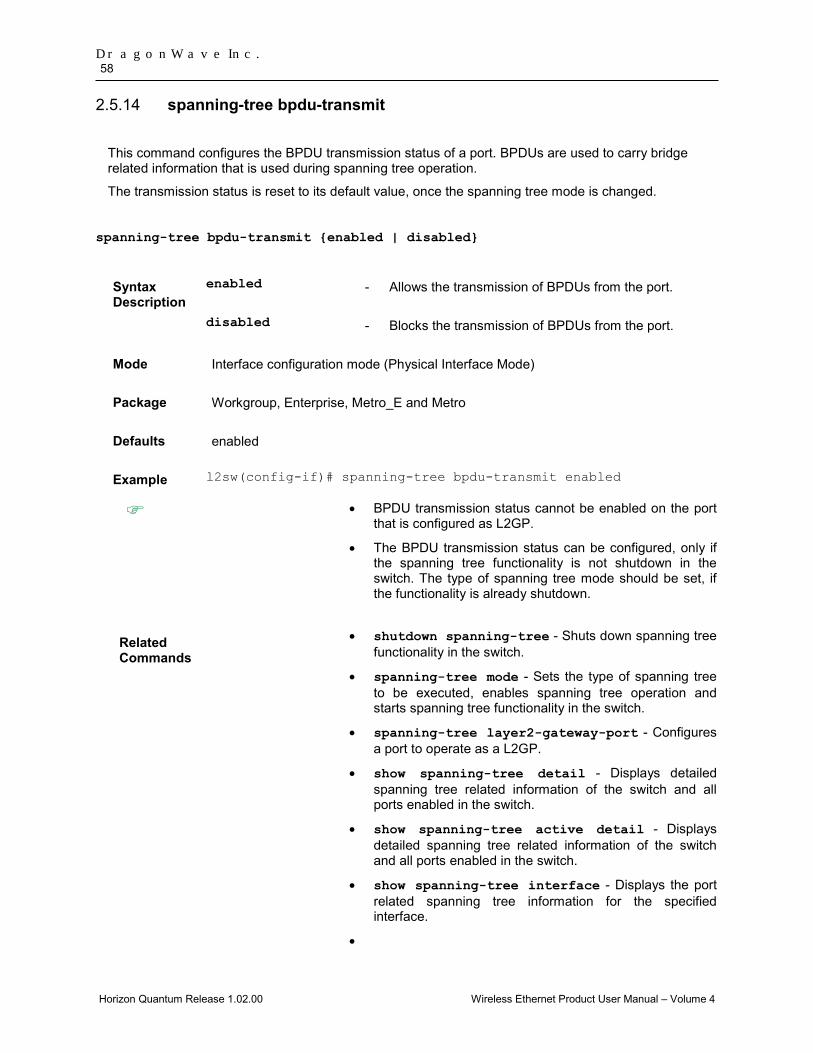
DragonWave Inc. 58
Horizon Quantum Release 1.02.00 Wireless Ethernet Product User Manual – Volume 4
spanning-tree bpdu-transmit 2.5.14
This command configures the BPDU transmission status of a port. BPDUs are used to carry bridge related information that is used during spanning tree operation.
The transmission status is reset to its default value, once the spanning tree mode is changed.
spanning-tree bpdu-transmit {enabled | disabled}
Syntax Description
enabled - Allows the transmission of BPDUs from the port.
disabled - Blocks the transmission of BPDUs from the port.
Mode Interface configuration mode (Physical Interface Mode)
Package Workgroup, Enterprise, Metro_E and Metro
Defaults enabled
Example l2sw(config-if)# spanning-tree bpdu-transmit enabled
• BPDU transmission status cannot be enabled on the port that is configured as L2GP.
• The BPDU transmission status can be configured, only if the spanning tree functionality is not shutdown in the switch. The type of spanning tree mode should be set, if the functionality is already shutdown.
Related Commands
• shutdown spanning-tree - Shuts down spanning tree functionality in the switch.
• spanning-tree mode - Sets the type of spanning tree to be executed, enables spanning tree operation and starts spanning tree functionality in the switch.
• spanning-tree layer2-gateway-port - Configures a port to operate as a L2GP.
• show spanning-tree detail - Displays detailed spanning tree related information of the switch and all ports enabled in the switch.
• show spanning-tree active detail - Displays detailed spanning tree related information of the switch and all ports enabled in the switch.
• show spanning-tree interface - Displays the port related spanning tree information for the specified interface.
•

Layer 2 Switch Feature 59
Horizon Quantum Release 1.02.00 Wireless Ethernet Product User Manual – Volume 4
spanning-tree loop-guard 2.5.15
This command enables the loop guard feature in a port.
The no form of this command disables the loop guard feature in the port. The loop guard feature is disabled, even if the spanning tree mode is changed.
This feature prevents the alternative or root ports from becoming designated ports due to failure in a unidirectional link. This feature is useful when the neighbor bridge is faulty, that is, the bridge cannot send BPDUs but continues to send data traffic.
spanning-tree loop-guard
no spanning-tree loop-guard
Mode Interface Configuration Mode (Physical Interface Mode)
Defaults Loop guard feature is disabled in all ports.
Example l2sw(config-if)# spanning-tree loop-guard
The loop guard feature can be configured, only if the spanning tree functionality is not shutdown in the switch. The type of spanning tree mode should be set, if the functionality is already shutdown.
Related commands
• shutdown spanning-tree - Shuts down spanning tree functionality in the switch.
• spanning-tree mode - Sets the type of spanning tree to be executed, enables spanning tree operation and starts spanning tree functionality in the switch.
• show spanning-tree detail - Displays detailed spanning tree related information of the switch and all ports enabled in the switch.
• show spanning-tree active detail - Displays detailed spanning tree related information of the switch and all ports enabled in the switch.
• show spanning-tree interface - Displays the port related spanning tree information for the specified interface.
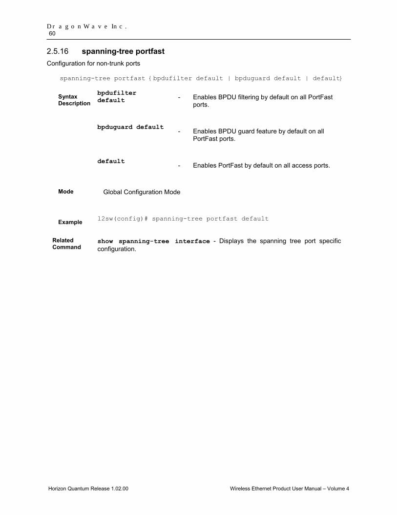
DragonWave Inc. 60
Horizon Quantum Release 1.02.00 Wireless Ethernet Product User Manual – Volume 4
spanning-tree portfast 2.5.16Configuration for non-trunk ports
spanning-tree portfast {bpdufilter default | bpduguard default | default}
Syntax Description
bpdufilter default - Enables BPDU filtering by default on all PortFast
ports.
bpduguard default
- Enables BPDU guard feature by default on all PortFast ports.
default
- Enables PortFast by default on all access ports.
Mode Global Configuration Mode
Example l2sw(config)# spanning-tree portfast default
Related Command
show spanning-tree interface - Displays the spanning tree port specific configuration.

Layer 2 Switch Feature 61
Horizon Quantum Release 1.02.00 Wireless Ethernet Product User Manual – Volume 4
debug spanning-tree 2.5.17
This command enables the tracing of the STP module as per the configured debug levels. The trace statements are generated for the configured trace levels.
The no form of this command disables the tracing of the STP module as per the configured debug levels. The trace statements are not generated for the configured trace levels.
This command allows combination of debug levels to be configured (that is, more than one level of trace can be enabled or disabled). The debug levels are configured one after the other and not in single execution of the command.
Notes: when debug trace is enabled for spanning-tree, the corresponding logs will be added to the system event logs. Generating these event logs could slow down spanning-tree response time, and thus result in a longer outage time during rstp/mstp network topology reconstruct.
debug spanning-tree { global | { all | errors |init-shut | management | memory | bpdu | events | timer | state-machine { port-info | port-receive | port-role-selection | role-transition | state-transition | protocol-migration | topology-change | port-transmit | bridge-detection | pseudoInfo } | redundancy | sem-variables} [switch <context_name>]}
no debug spanning-tree {global | {all | errors | init-shut | management | memory | bpdu |events | timer | state-machine {port-info | port-receive | port-role-selection | role-transition | state-transition | protocol-migration | topology-change | port-transmit | bridge-detection | pseudoInfo } redundancy | sem-variables} [switch <context_name>]}
Syntax Description
global1 - Generates debug statements for global traces. This trace is used for providing status of STP task initialization, memory-pool creation and event-reception in STP task.
all - Generates debug statements for all kinds of traces.
errors - Generates debug statements for all failure traces.
init-shut - Generates debug statements for init and shutdown traces. This
trace is generated on failed and successful initialization and shutting down of STP related module and memory.
management - Generates debug statements for management traces. This trace is generated whenever you configure any of the STP features.
memory - Generates debug statements for memory related traces. This trace is generated on failed and successful allocation of memory for STP process.
bpdu - Generates debug statements for BPDU related traces. This trace is generated on failed and successful reception,
1 This parameter is specific to Mulitple Instance.

DragonWave Inc. 62
Horizon Quantum Release 1.02.00 Wireless Ethernet Product User Manual – Volume 4
transmission and processing of BPDUs.
timer - Generates debug statements for timer module traces. This trace is generated on failed and successful start, stop and restart of STP timers.
events - Generates debug statements for event handling traces. This trace is generated to denote events that are posted to STP configuration queue whenever you configure any of the STP features.
state machine
- Generates debug statements to denote the event and state of the selected SEM. The options are:
• port-info - Generates debug statements for port information SEM.
• port-receive - Generates debug statements for port receive SEM.
• port-role-selection - Generates debug statements for role selection SEM.
• role-transition - Generates debug statements for role transition SEM.
• state-transition - Generates debug statements for state transition SEM.
• protocol-migration - Generates debug statements for protocol migration SEM.
• topology-change - Generates debug statements for topology change SEM.
• port-transmit - Generates debug statements for port transmit SEM.
• bridge-detection - Generates debug statements for bridge detection SEM.
• pseudoInfo - Generates debug statements for port receive pseudo information SEM.
redundancy - Generates debug statements for redundancy code flow traces. This trace is generated in standby node STP while taking backup of configuration information from active node.
sem-variables
- Generates debug statements for state machine variable changes traces. This trace is generated on failed and successful creation and deletion of semaphore.

Layer 2 Switch Feature 63
Horizon Quantum Release 1.02.00 Wireless Ethernet Product User Manual – Volume 4
switch - Configures the tracing of the STP module for the specified context. This value represents unique name of the switch context. This value is a string whose maximum size is 32. This parameter is specific to multiple instance feature.
Mode Privileged EXEC Mode
Defaults Tracing of the STP module is disabled
Example l2sw# debug spanning-tree all
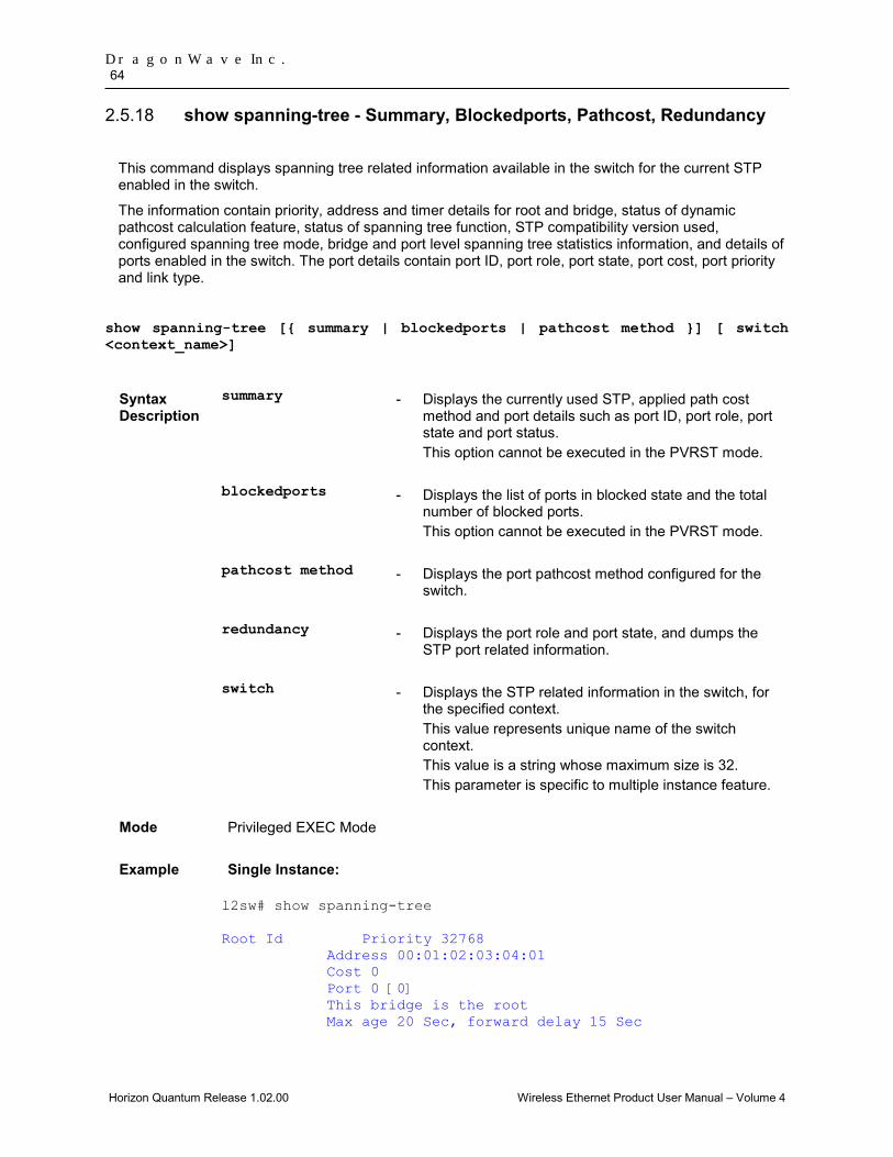
DragonWave Inc. 64
Horizon Quantum Release 1.02.00 Wireless Ethernet Product User Manual – Volume 4
show spanning-tree - Summary, Blockedports, Pathcost, Redundancy 2.5.18
This command displays spanning tree related information available in the switch for the current STP enabled in the switch.
The information contain priority, address and timer details for root and bridge, status of dynamic pathcost calculation feature, status of spanning tree function, STP compatibility version used, configured spanning tree mode, bridge and port level spanning tree statistics information, and details of ports enabled in the switch. The port details contain port ID, port role, port state, port cost, port priority and link type.
show spanning-tree [{ summary | blockedports | pathcost method }] [ switch <context_name>]
Syntax Description
summary - Displays the currently used STP, applied path cost method and port details such as port ID, port role, port state and port status. This option cannot be executed in the PVRST mode.
blockedports - Displays the list of ports in blocked state and the total number of blocked ports. This option cannot be executed in the PVRST mode.
pathcost method - Displays the port pathcost method configured for the switch.
redundancy - Displays the port role and port state, and dumps the STP port related information.
switch - Displays the STP related information in the switch, for the specified context. This value represents unique name of the switch context. This value is a string whose maximum size is 32. This parameter is specific to multiple instance feature.
Mode Privileged EXEC Mode
Example Single Instance: l2sw# show spanning-tree Root Id Priority 32768 Address 00:01:02:03:04:01 Cost 0 Port 0 [0] This bridge is the root Max age 20 Sec, forward delay 15 Sec
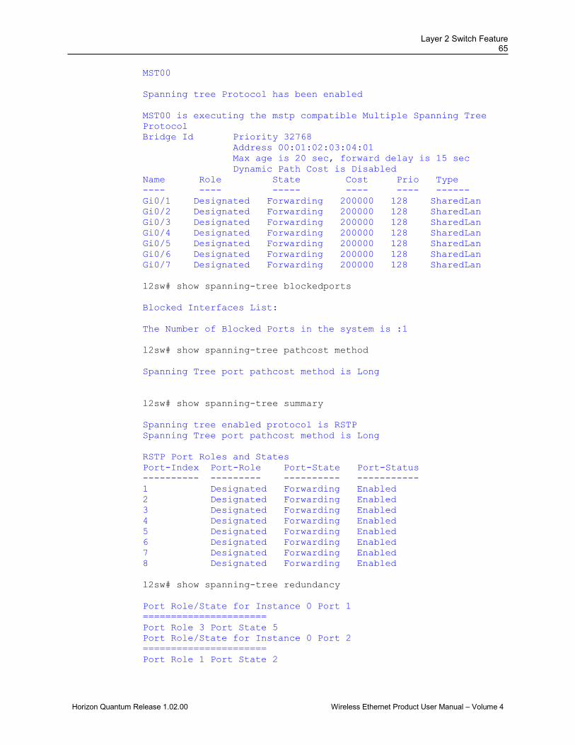
Layer 2 Switch Feature 65
Horizon Quantum Release 1.02.00 Wireless Ethernet Product User Manual – Volume 4
MST00 Spanning tree Protocol has been enabled MST00 is executing the mstp compatible Multiple Spanning Tree Protocol Bridge Id Priority 32768 Address 00:01:02:03:04:01 Max age is 20 sec, forward delay is 15 sec Dynamic Path Cost is Disabled Name Role State Cost Prio Type ---- ---- ----- ---- ---- ------ Gi0/1 Designated Forwarding 200000 128 SharedLan Gi0/2 Designated Forwarding 200000 128 SharedLan Gi0/3 Designated Forwarding 200000 128 SharedLan Gi0/4 Designated Forwarding 200000 128 SharedLan Gi0/5 Designated Forwarding 200000 128 SharedLan Gi0/6 Designated Forwarding 200000 128 SharedLan Gi0/7 Designated Forwarding 200000 128 SharedLan l2sw# show spanning-tree blockedports Blocked Interfaces List: The Number of Blocked Ports in the system is :1 l2sw# show spanning-tree pathcost method Spanning Tree port pathcost method is Long l2sw# show spanning-tree summary Spanning tree enabled protocol is RSTP Spanning Tree port pathcost method is Long RSTP Port Roles and States Port-Index Port-Role Port-State Port-Status ---------- --------- ---------- ----------- 1 Designated Forwarding Enabled 2 Designated Forwarding Enabled 3 Designated Forwarding Enabled 4 Designated Forwarding Enabled 5 Designated Forwarding Enabled 6 Designated Forwarding Enabled 7 Designated Forwarding Enabled 8 Designated Forwarding Enabled l2sw# show spanning-tree redundancy Port Role/State for Instance 0 Port 1 ====================== Port Role 3 Port State 5 Port Role/State for Instance 0 Port 2 ====================== Port Role 1 Port State 2
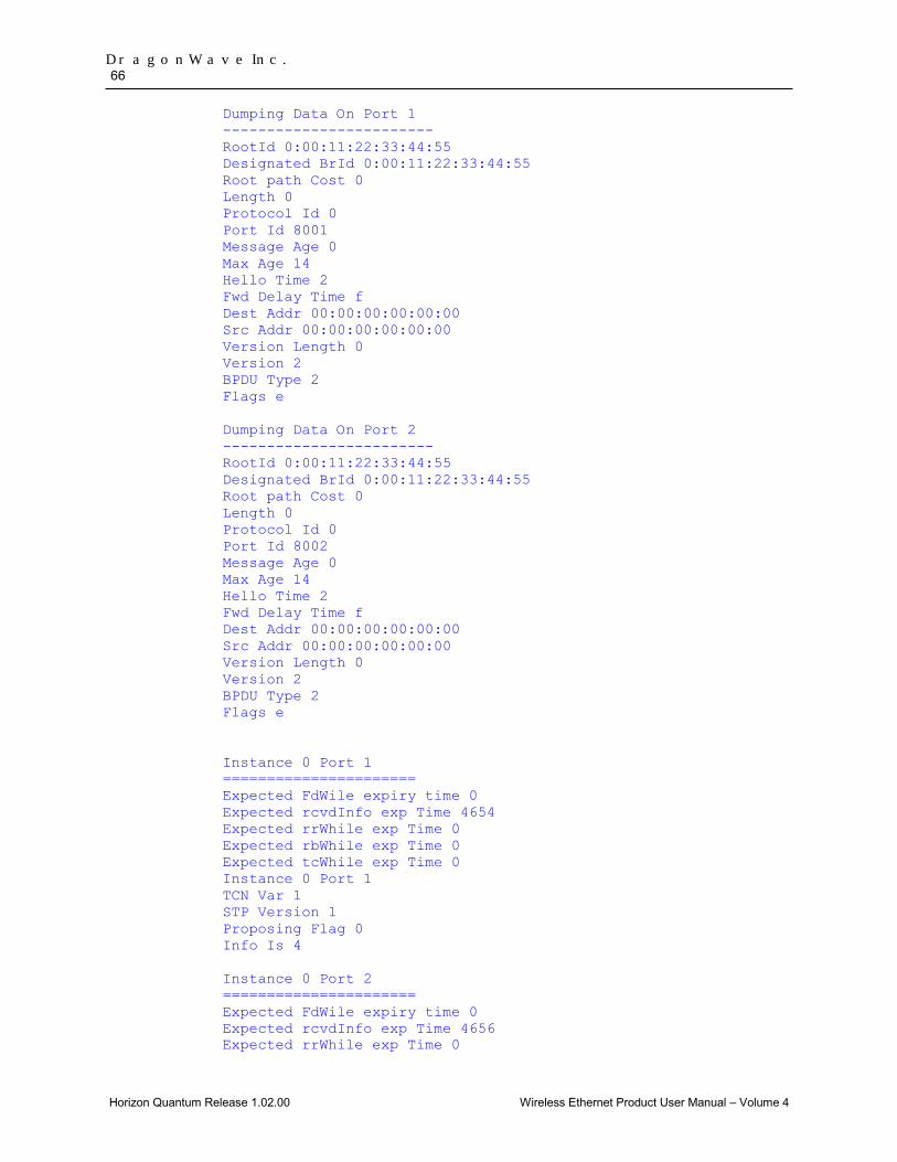
DragonWave Inc. 66
Horizon Quantum Release 1.02.00 Wireless Ethernet Product User Manual – Volume 4
Dumping Data On Port 1 ------------------------ RootId 0:00:11:22:33:44:55 Designated BrId 0:00:11:22:33:44:55 Root path Cost 0 Length 0 Protocol Id 0 Port Id 8001 Message Age 0 Max Age 14 Hello Time 2 Fwd Delay Time f Dest Addr 00:00:00:00:00:00 Src Addr 00:00:00:00:00:00 Version Length 0 Version 2 BPDU Type 2 Flags e Dumping Data On Port 2 ------------------------ RootId 0:00:11:22:33:44:55 Designated BrId 0:00:11:22:33:44:55 Root path Cost 0 Length 0 Protocol Id 0 Port Id 8002 Message Age 0 Max Age 14 Hello Time 2 Fwd Delay Time f Dest Addr 00:00:00:00:00:00 Src Addr 00:00:00:00:00:00 Version Length 0 Version 2 BPDU Type 2 Flags e Instance 0 Port 1 ====================== Expected FdWile expiry time 0 Expected rcvdInfo exp Time 4654 Expected rrWhile exp Time 0 Expected rbWhile exp Time 0 Expected tcWhile exp Time 0 Instance 0 Port 1 TCN Var 1 STP Version 1 Proposing Flag 0 Info Is 4 Instance 0 Port 2 ====================== Expected FdWile expiry time 0 Expected rcvdInfo exp Time 4656 Expected rrWhile exp Time 0
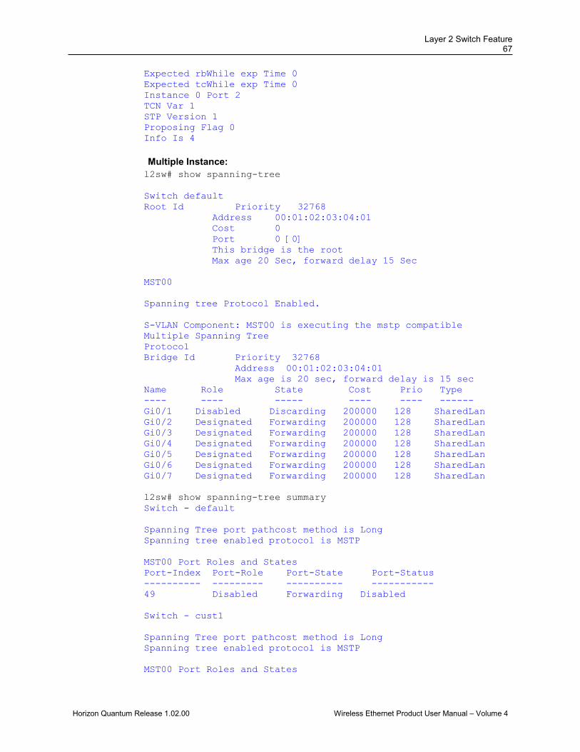
Layer 2 Switch Feature 67
Horizon Quantum Release 1.02.00 Wireless Ethernet Product User Manual – Volume 4
Expected rbWhile exp Time 0 Expected tcWhile exp Time 0 Instance 0 Port 2 TCN Var 1 STP Version 1 Proposing Flag 0 Info Is 4 Multiple Instance: l2sw# show spanning-tree Switch default Root Id Priority 32768 Address 00:01:02:03:04:01 Cost 0 Port 0 [0] This bridge is the root Max age 20 Sec, forward delay 15 Sec MST00 Spanning tree Protocol Enabled. S-VLAN Component: MST00 is executing the mstp compatible Multiple Spanning Tree Protocol Bridge Id Priority 32768 Address 00:01:02:03:04:01 Max age is 20 sec, forward delay is 15 sec Name Role State Cost Prio Type ---- ---- ----- ---- ---- ------ Gi0/1 Disabled Discarding 200000 128 SharedLan Gi0/2 Designated Forwarding 200000 128 SharedLan Gi0/3 Designated Forwarding 200000 128 SharedLan Gi0/4 Designated Forwarding 200000 128 SharedLan Gi0/5 Designated Forwarding 200000 128 SharedLan Gi0/6 Designated Forwarding 200000 128 SharedLan Gi0/7 Designated Forwarding 200000 128 SharedLan l2sw# show spanning-tree summary Switch - default Spanning Tree port pathcost method is Long Spanning tree enabled protocol is MSTP MST00 Port Roles and States Port-Index Port-Role Port-State Port-Status ---------- --------- ---------- ----------- 49 Disabled Forwarding Disabled Switch - cust1 Spanning Tree port pathcost method is Long Spanning tree enabled protocol is MSTP MST00 Port Roles and States
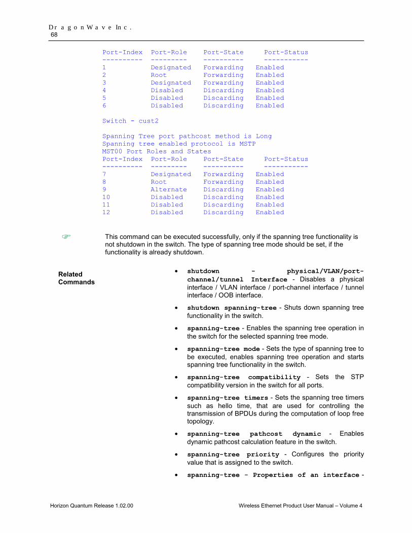
DragonWave Inc. 68
Horizon Quantum Release 1.02.00 Wireless Ethernet Product User Manual – Volume 4
Port-Index Port-Role Port-State Port-Status ---------- --------- ---------- ----------- 1 Designated Forwarding Enabled 2 Root Forwarding Enabled 3 Designated Forwarding Enabled 4 Disabled Discarding Enabled 5 Disabled Discarding Enabled 6 Disabled Discarding Enabled Switch - cust2 Spanning Tree port pathcost method is Long Spanning tree enabled protocol is MSTP MST00 Port Roles and States Port-Index Port-Role Port-State Port-Status ---------- --------- ---------- ----------- 7 Designated Forwarding Enabled 8 Root Forwarding Enabled 9 Alternate Discarding Enabled 10 Disabled Discarding Enabled 11 Disabled Discarding Enabled 12 Disabled Discarding Enabled
This command can be executed successfully, only if the spanning tree functionality is not shutdown in the switch. The type of spanning tree mode should be set, if the functionality is already shutdown.
Related Commands
• shutdown - physical/VLAN/port-channel/tunnel Interface - Disables a physical interface / VLAN interface / port-channel interface / tunnel interface / OOB interface.
• shutdown spanning-tree - Shuts down spanning tree functionality in the switch.
• spanning-tree - Enables the spanning tree operation in the switch for the selected spanning tree mode.
• spanning-tree mode - Sets the type of spanning tree to be executed, enables spanning tree operation and starts spanning tree functionality in the switch.
• spanning-tree compatibility - Sets the STP compatibility version in the switch for all ports.
• spanning-tree timers - Sets the spanning tree timers such as hello time, that are used for controlling the transmission of BPDUs during the computation of loop free topology.
• spanning-tree pathcost dynamic - Enables dynamic pathcost calculation feature in the switch.
• spanning-tree priority - Configures the priority value that is assigned to the switch.
• spanning-tree - Properties of an interface -

Layer 2 Switch Feature 69
Horizon Quantum Release 1.02.00 Wireless Ethernet Product User Manual – Volume 4
Configures the port related spanning tree information for all kinds of STPs.
• spanning-tree mst- Properties of an interface for MSTP - Configures the port related spanning tree information for a specified MSTI.
• spanning-tree mst hello-time - Configures the hello time for an interface that is enabled.
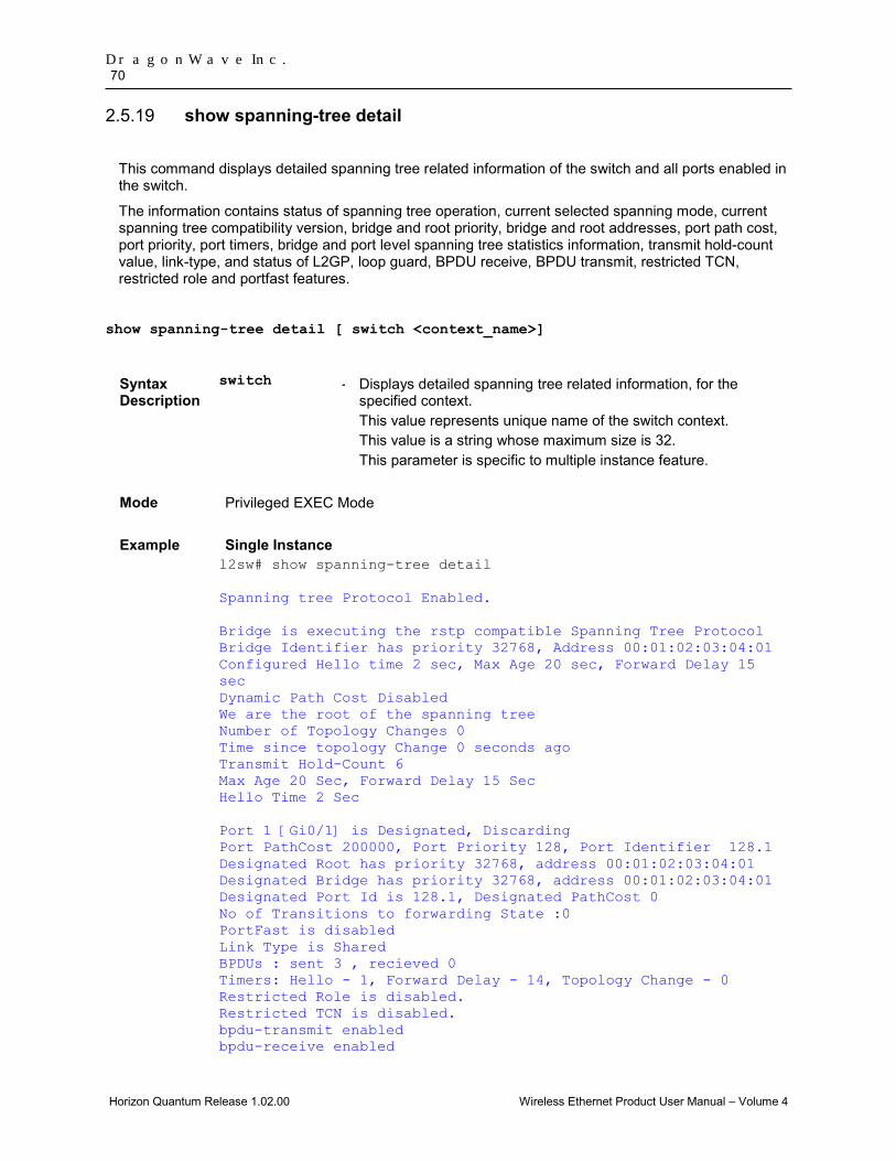
DragonWave Inc. 70
Horizon Quantum Release 1.02.00 Wireless Ethernet Product User Manual – Volume 4
show spanning-tree detail 2.5.19
This command displays detailed spanning tree related information of the switch and all ports enabled in the switch.
The information contains status of spanning tree operation, current selected spanning mode, current spanning tree compatibility version, bridge and root priority, bridge and root addresses, port path cost, port priority, port timers, bridge and port level spanning tree statistics information, transmit hold-count value, link-type, and status of L2GP, loop guard, BPDU receive, BPDU transmit, restricted TCN, restricted role and portfast features.
show spanning-tree detail [ switch <context_name>]
Syntax Description
switch - Displays detailed spanning tree related information, for the specified context. This value represents unique name of the switch context. This value is a string whose maximum size is 32. This parameter is specific to multiple instance feature.
Mode Privileged EXEC Mode
Example Single Instance l2sw# show spanning-tree detail Spanning tree Protocol Enabled. Bridge is executing the rstp compatible Spanning Tree Protocol Bridge Identifier has priority 32768, Address 00:01:02:03:04:01 Configured Hello time 2 sec, Max Age 20 sec, Forward Delay 15 sec Dynamic Path Cost Disabled We are the root of the spanning tree Number of Topology Changes 0 Time since topology Change 0 seconds ago Transmit Hold-Count 6 Max Age 20 Sec, Forward Delay 15 Sec Hello Time 2 Sec Port 1 [Gi0/1] is Designated, Discarding Port PathCost 200000, Port Priority 128, Port Identifier 128.1 Designated Root has priority 32768, address 00:01:02:03:04:01 Designated Bridge has priority 32768, address 00:01:02:03:04:01 Designated Port Id is 128.1, Designated PathCost 0 No of Transitions to forwarding State :0 PortFast is disabled Link Type is Shared BPDUs : sent 3 , recieved 0 Timers: Hello - 1, Forward Delay - 14, Topology Change - 0 Restricted Role is disabled. Restricted TCN is disabled. bpdu-transmit enabled bpdu-receive enabled

Layer 2 Switch Feature 71
Horizon Quantum Release 1.02.00 Wireless Ethernet Product User Manual – Volume 4
Multiple Instance: l2sw# show spanning-tree detail switch default Switch default MST00 is executing the mstp compatible Multiple Spanning Tree Protocol Bridge Identifier has Priority 32768, Address 00:51:02:03:04:05 Configured Max age 20 sec, Forward delay 15 sec Configured Hello Time 2 sec We are root of the spanning tree Current Root has priority 32768, address 00:51:02:03:04:05 cost of root path is 0 Number of Topology Changes 1, Time since topology Change 82 seconds ago Transmit Hold-Count 3 Times : Max age 20 Sec,Forward delay 15 Sec Port 1 [Gi0/1] of MST00 is Designated, Forwarding Gi0/1 is operating in the MSTP Mode Port path cost 200000, Port priority 128, Port Identifier 128.1. Port HelloTime 2, Timers: Hello - 0, Forward Delay - 0, Topology Change - 0 Designated root has priority 32768, address 00:51:02:03:04:05 Designated Bridge has priority 32768, address 00:51:02:03:04:05 Designated Port Id is 128.1, Designated pathcost is 0 Operational Forward delay 15, Max age 20 Number of Transitions to forwarding State : 1 PortFast is disabled Link Type is Shared BPDUs : sent 58, recieved 0 Restricted Role is disabled. Restricted TCN is disabled.
This command can be executed successfully, only if the spanning tree functionality is not shutdown in the switch. The type of spanning tree mode should be set, if the functionality is already shutdown.
Related Commands
• shutdown - physical/VLAN/port-channel/tunnel Interface - Disables a physical interface / VLAN interface / port-channel interface / tunnel interface / OOB interface.
• shutdown spanning-tree - Shuts down spanning tree functionality in the switch.
• spanning-tree - Enables the spanning tree operation in the switch for the selected spanning tree mode.
• spanning-tree mode - Sets the type of spanning tree to be executed, enables spanning tree operation and starts spanning tree functionality in the switch.
• spanning-tree compatibility - Sets the STP compatibility version in the switch for all ports.
DragonWave Inc. 72
Horizon Quantum Release 1.02.00 Wireless Ethernet Product User Manual – Volume 4
• spanning-tree timers - Sets the spanning tree timers such as hello time, that are used for controlling the transmission of BPDUs during the computation of loop free topology.
• spanning-tree transmit hold-count - Sets the transmit hold-count value for the switch.
• clear spanning-tree counters - Deletes all bridge and port level spanning tree statistics information.
• spanning-tree pathcost dynamic - Enables dynamic pathcost calculation feature in the switch.
• spanning-tree priority - Configures the priority value that is assigned to the switch.
• spanning-tree - Properties of an interface - Configures the port related spanning tree information for all kinds of STPs.
• spanning-tree loop-guard - Enables the loop guard feature in a port.
• spanning-tree mst- Properties of an interface for MSTP - Configures the port related spanning tree information for a specified MSTI.
• spanning-tree mst hello-time - Configures the hello time for an interface that is enabled.

Layer 2 Switch Feature 73
Horizon Quantum Release 1.02.00 Wireless Ethernet Product User Manual – Volume 4
show spanning-tree active 2.5.20
This command displays spanning tree related information available in the switch for the current STP enabled in the switch.
The information contains priority, address and timer details for root and bridge, status of dynamic pathcost calculation feature, status of spanning tree function, STP compatibility version used, configured spanning tree mode, bridge and port level spanning tree statistics information, and details of ports enabled in the switch. The port details contain port ID, port role, port state, port cost, port priority and link type.
show spanning-tree active [detail] [ switch <context_name>]
Syntax Description
detail - Displays detailed spanning tree related information of the switch and all ports enabled in the switch. The information contains status of spanning tree operation, current selected spanning mode, current spanning tree compatibility version, bridge and root priority, bridge and root addresses, port path cost, port priority, port timers, bridge and port level spanning tree statistics information, transmit hold-count value, link-type, and status of L2GP, loop guard, BPDU receive, BPDU transmit, restricted TCN, restricted role and portfast features.
switch - Displays spanning tree related information available in the switch, for the specified context. This value represents unique name of the switch context. This value is a string whose maximum size is 32. This parameter is specific to multiple instance feature.
Mode Privileged EXEC Mode
Example Single Instance: l2sw# show spanning-tree active Root Id Priority 32768 Address 00:01:02:03:04:01 Cost 200000 Port 1 [Gi0/1] Max age 20 Sec, forward delay 15 Sec MST00 Spanning tree Protocol has been enabled MST00 is executing the mstp compatible Multiple Spanning Tree Protocol Bridge Id Priority 32768 Address 00:02:02:03:04:01 Max age is 20 sec, forward delay is 15 sec Dynamic Path Cost is Disabled

DragonWave Inc. 74
Horizon Quantum Release 1.02.00 Wireless Ethernet Product User Manual – Volume 4
Name Role State Cost Prio Type ---- ---- ----- ---- ---- ------ Gi0/1 Root Forwarding 200000 128 SharedLan Multiple Instance: l2sw# show spanning-tree active switch default Switch default Root Id Priority 32768 Address 00:51:02:03:04:05 Cost 0 Port 0 [0] This bridge is the root Max age 20 Sec, forward delay 15 Sec MST00 MST00 is executing the mstp compatible Multiple Spanning Tree Protocol Bridge Id Priority 32768 Address 00:51:02:03:04:05 Max age is 20 sec, forward delay is 15 sec Name Role State Cost Prio Type ---- ---- ----- ---- ---- ------ Gi0/1 Designated Forwarding 200000 128 SharedLan
This command can be executed successfully, only if the spanning tree functionality is not shutdown in the switch. The type of spanning tree mode should be set, if the functionality is already shutdown.
Related Commands
• shutdown - physical/VLAN/port-channel/tunnel Interface - Disables a physical interface / VLAN interface / port-channel interface / tunnel interface / OOB interface.
• shutdown spanning-tree - Shuts down spanning tree functionality in the switch.
• spanning-tree - Enables the spanning tree operation in the switch for the selected spanning tree mode.
• spanning-tree mode - Sets the type of spanning tree to be executed, enables spanning tree operation and starts spanning tree functionality in the switch.
• spanning-tree compatibility - Sets the STP compatibility version in the switch for all ports.
• spanning-tree timers - Sets the spanning tree timers such as hello time, that are used for controlling the transmission of BPDUs during the computation of loop free topology.
• spanning-tree transmit hold-count - Sets the transmit hold-count value for the switch.
• clear spanning-tree counters - Deletes all bridge

Layer 2 Switch Feature 75
Horizon Quantum Release 1.02.00 Wireless Ethernet Product User Manual – Volume 4
and port level spanning tree statistics information.
• spanning-tree pathcost dynamic - Enables dynamic pathcost calculation feature in the switch.
• spanning-tree priority - Configures the priority value that is assigned to the switch.
• spanning-tree - Properties of an interface - Configures the port related spanning tree information for all kinds of STPs.
• spanning-tree loop-guard - Enables the loop guard feature in a port.
• spanning-tree mst- Properties of an interface for MSTP - Configures the port related spanning tree information for a specified MSTI.
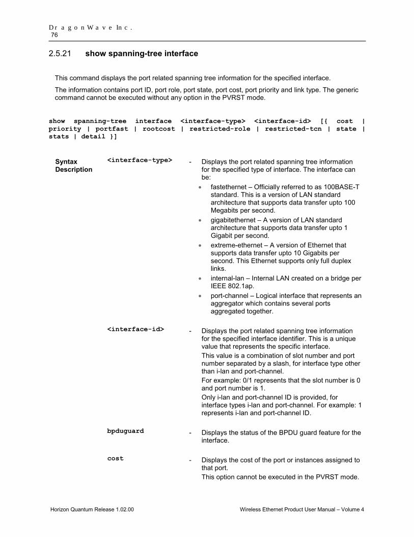
DragonWave Inc. 76
Horizon Quantum Release 1.02.00 Wireless Ethernet Product User Manual – Volume 4
show spanning-tree interface 2.5.21
This command displays the port related spanning tree information for the specified interface.
The information contains port ID, port role, port state, port cost, port priority and link type. The generic command cannot be executed without any option in the PVRST mode.
show spanning-tree interface <interface-type> <interface-id> [{ cost | priority | portfast | rootcost | restricted-role | restricted-tcn | state | stats | detail }]
Syntax Description
<interface-type> - Displays the port related spanning tree information for the specified type of interface. The interface can be: • fastethernet – Officially referred to as 100BASE-T
standard. This is a version of LAN standard architecture that supports data transfer upto 100 Megabits per second.
• gigabitethernet – A version of LAN standard architecture that supports data transfer upto 1 Gigabit per second.
• extreme-ethernet – A version of Ethernet that supports data transfer upto 10 Gigabits per second. This Ethernet supports only full duplex links.
• internal-lan – Internal LAN created on a bridge per IEEE 802.1ap.
• port-channel – Logical interface that represents an aggregator which contains several ports aggregated together.
<interface-id> - Displays the port related spanning tree information
for the specified interface identifier. This is a unique value that represents the specific interface. This value is a combination of slot number and port number separated by a slash, for interface type other than i-lan and port-channel. For example: 0/1 represents that the slot number is 0 and port number is 1. Only i-lan and port-channel ID is provided, for interface types i-lan and port-channel. For example: 1 represents i-lan and port-channel ID.
bpduguard - Displays the status of the BPDU guard feature for the interface.
cost - Displays the cost of the port or instances assigned to that port. This option cannot be executed in the PVRST mode.
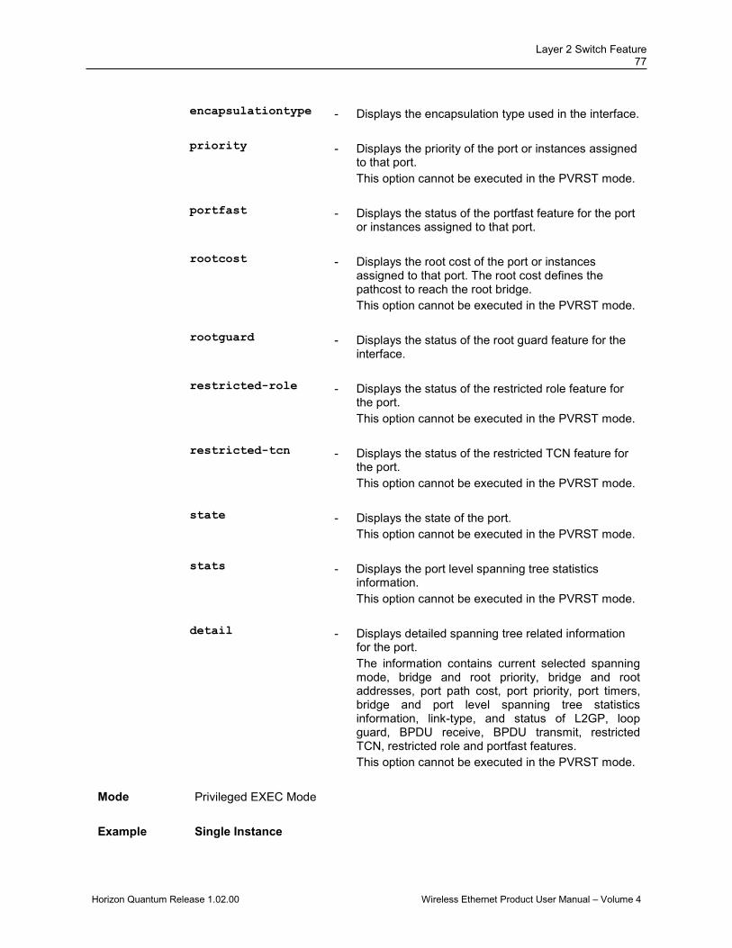
Layer 2 Switch Feature 77
Horizon Quantum Release 1.02.00 Wireless Ethernet Product User Manual – Volume 4
encapsulationtype - Displays the encapsulation type used in the interface.
priority - Displays the priority of the port or instances assigned
to that port. This option cannot be executed in the PVRST mode.
portfast - Displays the status of the portfast feature for the port or instances assigned to that port.
rootcost - Displays the root cost of the port or instances assigned to that port. The root cost defines the pathcost to reach the root bridge. This option cannot be executed in the PVRST mode.
rootguard - Displays the status of the root guard feature for the interface.
restricted-role - Displays the status of the restricted role feature for the port. This option cannot be executed in the PVRST mode.
restricted-tcn - Displays the status of the restricted TCN feature for the port. This option cannot be executed in the PVRST mode.
state - Displays the state of the port. This option cannot be executed in the PVRST mode.
stats - Displays the port level spanning tree statistics information. This option cannot be executed in the PVRST mode.
detail - Displays detailed spanning tree related information for the port. The information contains current selected spanning mode, bridge and root priority, bridge and root addresses, port path cost, port priority, port timers, bridge and port level spanning tree statistics information, link-type, and status of L2GP, loop guard, BPDU receive, BPDU transmit, restricted TCN, restricted role and portfast features. This option cannot be executed in the PVRST mode.
Mode Privileged EXEC Mode
Example Single Instance
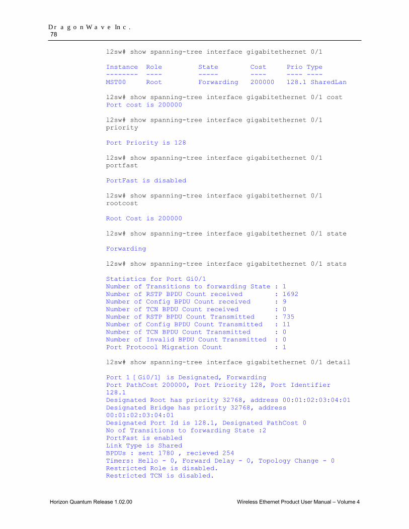
DragonWave Inc. 78
Horizon Quantum Release 1.02.00 Wireless Ethernet Product User Manual – Volume 4
l2sw# show spanning-tree interface gigabitethernet 0/1 Instance Role State Cost Prio Type -------- ---- ----- ---- ---- ---- MST00 Root Forwarding 200000 128.1 SharedLan l2sw# show spanning-tree interface gigabitethernet 0/1 cost Port cost is 200000 l2sw# show spanning-tree interface gigabitethernet 0/1 priority Port Priority is 128 l2sw# show spanning-tree interface gigabitethernet 0/1 portfast PortFast is disabled l2sw# show spanning-tree interface gigabitethernet 0/1 rootcost Root Cost is 200000 l2sw# show spanning-tree interface gigabitethernet 0/1 state Forwarding l2sw# show spanning-tree interface gigabitethernet 0/1 stats Statistics for Port Gi0/1 Number of Transitions to forwarding State : 1 Number of RSTP BPDU Count received : 1692 Number of Config BPDU Count received : 9 Number of TCN BPDU Count received : 0 Number of RSTP BPDU Count Transmitted : 735 Number of Config BPDU Count Transmitted : 11 Number of TCN BPDU Count Transmitted : 0 Number of Invalid BPDU Count Transmitted : 0 Port Protocol Migration Count : 1 l2sw# show spanning-tree interface gigabitethernet 0/1 detail Port 1 [Gi0/1] is Designated, Forwarding Port PathCost 200000, Port Priority 128, Port Identifier 128.1 Designated Root has priority 32768, address 00:01:02:03:04:01 Designated Bridge has priority 32768, address 00:01:02:03:04:01 Designated Port Id is 128.1, Designated PathCost 0 No of Transitions to forwarding State :2 PortFast is enabled Link Type is Shared BPDUs : sent 1780 , recieved 254 Timers: Hello - 0, Forward Delay - 0, Topology Change - 0 Restricted Role is disabled. Restricted TCN is disabled.
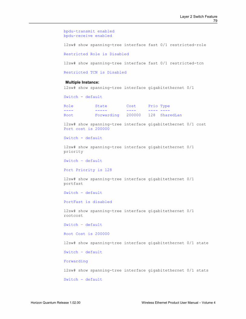
Layer 2 Switch Feature 79
Horizon Quantum Release 1.02.00 Wireless Ethernet Product User Manual – Volume 4
bpdu-transmit enabled bpdu-receive enabled l2sw# show spanning-tree interface fast 0/1 restricted-role Restricted Role is Disabled l2sw# show spanning-tree interface fast 0/1 restricted-tcn Restricted TCN is Disabled Multiple Instance: l2sw# show spanning-tree interface gigabitethernet 0/1 Switch - default Role State Cost Prio Type ---- ----- ---- ---- ---- Root Forwarding 200000 128 SharedLan l2sw# show spanning-tree interface gigabitethernet 0/1 cost Port cost is 200000 Switch - default l2sw# show spanning-tree interface gigabitethernet 0/1 priority Switch – default Port Priority is 128 l2sw# show spanning-tree interface gigabitethernet 0/1 portfast Switch – default PortFast is disabled l2sw# show spanning-tree interface gigabitethernet 0/1 rootcost Switch – default Root Cost is 200000 l2sw# show spanning-tree interface gigabitethernet 0/1 state Switch – default Forwarding l2sw# show spanning-tree interface gigabitethernet 0/1 stats Switch – default
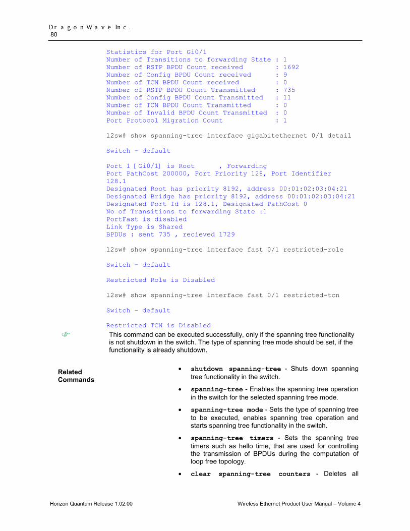
DragonWave Inc. 80
Horizon Quantum Release 1.02.00 Wireless Ethernet Product User Manual – Volume 4
Statistics for Port Gi0/1 Number of Transitions to forwarding State : 1 Number of RSTP BPDU Count received : 1692 Number of Config BPDU Count received : 9 Number of TCN BPDU Count received : 0 Number of RSTP BPDU Count Transmitted : 735 Number of Config BPDU Count Transmitted : 11 Number of TCN BPDU Count Transmitted : 0 Number of Invalid BPDU Count Transmitted : 0 Port Protocol Migration Count : 1 l2sw# show spanning-tree interface gigabitethernet 0/1 detail Switch – default Port 1 [Gi0/1] is Root , Forwarding Port PathCost 200000, Port Priority 128, Port Identifier 128.1 Designated Root has priority 8192, address 00:01:02:03:04:21 Designated Bridge has priority 8192, address 00:01:02:03:04:21 Designated Port Id is 128.1, Designated PathCost 0 No of Transitions to forwarding State :1 PortFast is disabled Link Type is Shared BPDUs : sent 735 , recieved 1729 l2sw# show spanning-tree interface fast 0/1 restricted-role Switch – default Restricted Role is Disabled l2sw# show spanning-tree interface fast 0/1 restricted-tcn Switch – default Restricted TCN is Disabled
This command can be executed successfully, only if the spanning tree functionality is not shutdown in the switch. The type of spanning tree mode should be set, if the functionality is already shutdown.
Related Commands
• shutdown spanning-tree - Shuts down spanning tree functionality in the switch.
• spanning-tree - Enables the spanning tree operation in the switch for the selected spanning tree mode.
• spanning-tree mode - Sets the type of spanning tree to be executed, enables spanning tree operation and starts spanning tree functionality in the switch.
• spanning-tree timers - Sets the spanning tree timers such as hello time, that are used for controlling the transmission of BPDUs during the computation of loop free topology.
• clear spanning-tree counters - Deletes all
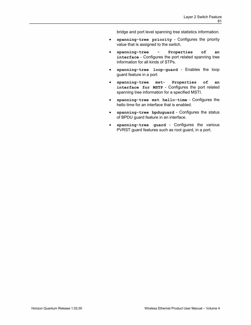
Layer 2 Switch Feature 81
Horizon Quantum Release 1.02.00 Wireless Ethernet Product User Manual – Volume 4
bridge and port level spanning tree statistics information.
• spanning-tree priority - Configures the priority value that is assigned to the switch.
• spanning-tree - Properties of an interface - Configures the port related spanning tree information for all kinds of STPs.
• spanning-tree loop-guard - Enables the loop guard feature in a port.
• spanning-tree mst- Properties of an interface for MSTP - Configures the port related spanning tree information for a specified MSTI.
• spanning-tree mst hello-time - Configures the hello time for an interface that is enabled.
• spanning-tree bpduguard - Configures the status of BPDU guard feature in an interface.
• spanning-tree guard - Configures the various PVRST guard features such as root guard, in a port.
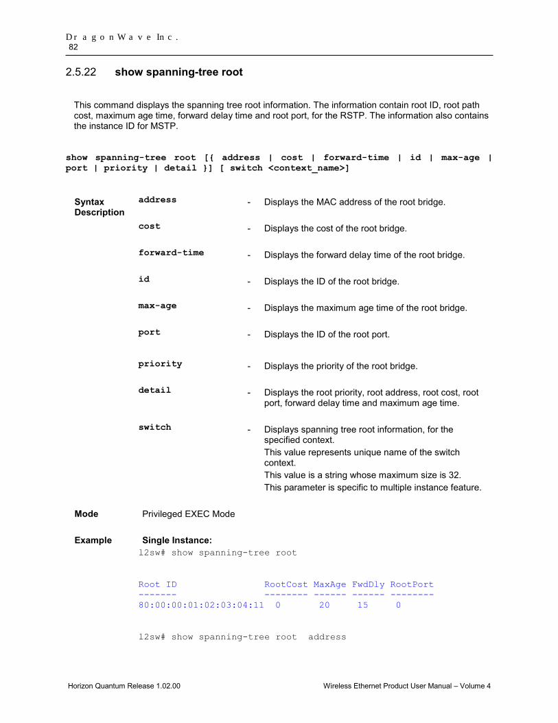
DragonWave Inc. 82
Horizon Quantum Release 1.02.00 Wireless Ethernet Product User Manual – Volume 4
show spanning-tree root 2.5.22
This command displays the spanning tree root information. The information contain root ID, root path cost, maximum age time, forward delay time and root port, for the RSTP. The information also contains the instance ID for MSTP.
show spanning-tree root [{ address | cost | forward-time | id | max-age | port | priority | detail }] [ switch <context_name>]
Syntax Description
address - Displays the MAC address of the root bridge.
cost - Displays the cost of the root bridge.
forward-time - Displays the forward delay time of the root bridge.
id - Displays the ID of the root bridge.
max-age - Displays the maximum age time of the root bridge.
port
- Displays the ID of the root port.
priority - Displays the priority of the root bridge.
detail - Displays the root priority, root address, root cost, root port, forward delay time and maximum age time.
switch - Displays spanning tree root information, for the specified context. This value represents unique name of the switch context. This value is a string whose maximum size is 32. This parameter is specific to multiple instance feature.
Mode Privileged EXEC Mode
Example Single Instance: l2sw# show spanning-tree root
Root ID RootCost MaxAge FwdDly RootPort ------- -------- ------ ------ -------- 80:00:00:01:02:03:04:11 0 20 15 0
l2sw# show spanning-tree root address

Layer 2 Switch Feature 83
Horizon Quantum Release 1.02.00 Wireless Ethernet Product User Manual – Volume 4
Root Bridge Address is 00:01:02:03:04:11
l2sw# show spanning-tree root cost
Root Cost is 0
l2sw# show spanning-tree root forward-time
Forward delay is 15 sec
l2sw# show spanning-tree root id
Root Bridge Id is 80:00:00:01:02:03:04:11
l2sw# show spanning-tree root max-age
Root MaxAge is 20
l2sw# show spanning-tree root port
Root Port is 0
l2sw# show spanning-tree root priority
Root Priority is 32768
l2sw# show spanning-tree root detail
We are the root of the Spanning Tree Root Id Priority 32768 Address 00:01:02:03:04:11 Cost 0 Port 0 Hello Time 2 Sec, Max Age 20 Sec, Forward Delay 15 Sec Multiple Instance: l2sw# show spanning-tree root
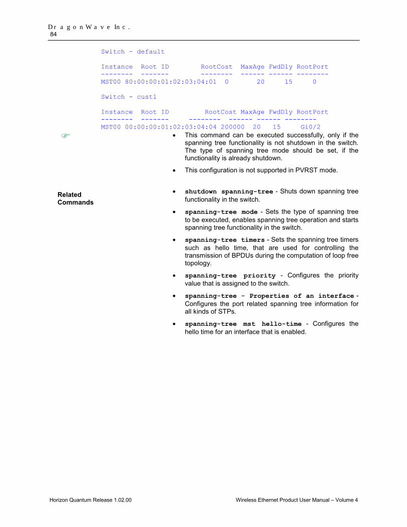
DragonWave Inc. 84
Horizon Quantum Release 1.02.00 Wireless Ethernet Product User Manual – Volume 4
Switch - default Instance Root ID RootCost MaxAge FwdDly RootPort -------- ------- -------- ------ ------ -------- MST00 80:00:00:01:02:03:04:01 0 20 15 0 Switch - cust1 Instance Root ID RootCost MaxAge FwdDly RootPort -------- ------- -------- ------ ------ -------- MST00 00:00:00:01:02:03:04:04 200000 20 15 Gi0/2
• This command can be executed successfully, only if the spanning tree functionality is not shutdown in the switch. The type of spanning tree mode should be set, if the functionality is already shutdown.
• This configuration is not supported in PVRST mode.
Related Commands
• shutdown spanning-tree - Shuts down spanning tree functionality in the switch.
• spanning-tree mode - Sets the type of spanning tree to be executed, enables spanning tree operation and starts spanning tree functionality in the switch.
• spanning-tree timers - Sets the spanning tree timers such as hello time, that are used for controlling the transmission of BPDUs during the computation of loop free topology.
• spanning-tree priority - Configures the priority value that is assigned to the switch.
• spanning-tree - Properties of an interface - Configures the port related spanning tree information for all kinds of STPs.
• spanning-tree mst hello-time - Configures the hello time for an interface that is enabled.

Layer 2 Switch Feature 85
Horizon Quantum Release 1.02.00 Wireless Ethernet Product User Manual – Volume 4
spanning-tree guard 2.5.23This command configures the various PVRST guard features such as root guard, in a port.
The no form of this command resets the guard feature to its default value. spanning-tree guard {root | none | loop
no spanning-tree guard
Syntax Description
root - Enables root guard feature in the port. This feature prevents the port from becoming root port or blocked port. The port changes to the root-inconsistent state, if the port receives superior BPDUs. The port automatically reverts back to forwarding state, once the superior BPDUs are not received.
none - Disables both root and loop guard features in the port.
loop - Enables loop guard feature in the port. This feature changes the port to an inconsistent state if no BPDUs are received. Thus isolating the failure and letting spanning tree converge to a stable topology until the port starts receiving BPDUs again. This feature is currently not supported.
Mode Interface Configuration mode (Physical Interface Mode)
Package Workgroup, Enterprise, Metro_E and Metro
Defaults None (No PVRST guard feature is enabled).
Example l2sw(config-if)# spanning-tree guard root
• This command can be executed successfully, only if the spanning tree functionality is not shutdown in the switch. The type of spanning tree mode should be set as pvrst.
• The guard feature can be configured only on ports that are set as trunk port.
Related Commands
• shutdown spanning-tree - Shuts down spanning tree functionality in the switch.
• spanning-tree mode - Sets the type of spanning tree to be executed, enables spanning tree operation and starts spanning tree functionality in the switch.
• show spanning-tree interface - Displays the port related spanning tree information for the specified interface.
• switchport mode trunk – Configures the port as trunk port.
DragonWave Inc. 86
Horizon Quantum Release 1.02.00 Wireless Ethernet Product User Manual – Volume 4
2.6 MSTP This section describes all MSTP related commands. These commands are available only if the switch MSTP_WANTED is set as yes during compilation of exe.
spanning-tree mst max-hops 2.6.1
This command configures the maximum number of hops permitted in the MSTP.
The no form of this command resets the maximum number of hops to its default value.
The number of hops represents the maximum number of switches that a packet can cross before it is dropped. The switch uses this value to avoid infinite looping of the packets, if it is elected as the root switch in the topology.
The root switch always transmits a BPDU with the maximum hop count value. The receiving switch decrements the value by one and propagates the BPDU with modified hop count value. The BPDU is discarded and the information held is aged out, when the count reaches 0.
This value ranges between 6 and 40.
spanning-tree mst max-hops <value(6-40)>
no spanning-tree mst max-hops
Mode Global Configuration Mode
Defaults 20
Example l2sw(config)#spanning-tree mst max-hops 10
This command can be executed successfully, only if the spanning tree functionality is not shutdown in the switch. The type of spanning tree mode should be set as mst.
Related Command
• shutdown spanning-tree - Shuts down spanning tree functionality in the switch.
• spanning-tree mode - Sets the type of spanning tree to be executed, enables spanning tree operation and starts spanning tree functionality in the switch.
• show spanning-tree mst - CIST or specified mst Instance -- Displays multiple spanning tree information for all MSTIs in the switch.
• show spanning-tree mst - Port Specific Configuration - Displays multiple spanning tree port specific information for the specified port.

Layer 2 Switch Feature 87
Horizon Quantum Release 1.02.00 Wireless Ethernet Product User Manual – Volume 4
spanning-tree mst configuration 2.6.2
This command enters into MSTP configuration mode, where instance specific and MST region configuration can be done.
spanning-tree mst configuration
Mode Global Configuration Mode
Example l2sw(config)#spanning-tree mst configuration
This command can be executed successfully, only if the spanning tree functionality is not shutdown in the switch. The type of spanning tree mode should be set as mst.
Related Command
• shutdown spanning-tree - Shuts down spanning tree functionality in the switch.
• spanning-tree mode - Sets the type of spanning tree to be executed, enables spanning tree operation and starts spanning tree functionality in the switch.
DragonWave Inc. 88
Horizon Quantum Release 1.02.00 Wireless Ethernet Product User Manual – Volume 4
spanning-tree mst max-instance 2.6.3
This command configures the maximum number of active MSTIs that can be created.
The no form of this command resets maximum MSTP instance value to its default value.
This configuration allows you to limit the number of spanning tree instances to be allowed in the switch.
This value ranges between 1 and 16.
spanning-tree mst max-instance <short(1-16)>
no spanning-tree mst max-instance
Mode Global Configuration Mode
Defaults 16
Example l2sw(config)# spanning-tree mst max-instance 40
This command can be executed successfully, only if the spanning tree functionality is not shutdown in the switch. The type of spanning tree mode should be set as mst.
Related Command
• shutdown spanning-tree - Shuts down spanning tree functionality in the switch.
• spanning-tree mode - Sets the type of spanning tree to be executed, enables spanning tree operation and starts spanning tree functionality in the switch.
• instance - Creates an MST instance and maps it to VLANs.
Layer 2 Switch Feature 89
Horizon Quantum Release 1.02.00 Wireless Ethernet Product User Manual – Volume 4
spanning-tree mst root 2.6.4
This command enables BPDU (Bridge Protocol Data Unit) transmission and reception on the interface. The no form of the command disables BPDU transmission and reception on the interface.
This command is a standardized implementation of the existing command; spanning-tree priority. It operates similar to the existing command.
spanning-tree mst {instance-id <instance-id(1-64)>} root {primary | secondary}
no spanning-tree mst {instance-id <instance-id(1-64)>} root
Syntax Description
instance-id <instance-id(1-64)>
- Configures the ID of MSTP instance already created in the switch. This value ranges between 1 and 64.. This option is applicable, only if the spanning tree mode is set as mst.
primary - Sets high enough priority (low value) for the switch
so that the switch can be made as the bridge root of the spanning-tree instance.
The priority value is set as 24576. secondary
- Sets the switch as a secondary root, if the primary root fails.
The priority value is set as 28672.
Mode Global Configuration Mode
Example l2sw(config)# spanning-tree mst instance-id 1 root secondary
Related Commands
• shutdown spanning-tree - Shuts down spanning tree functionality in the switch.
• spanning-tree mode - Sets the type of spanning tree to be executed, enables spanning tree operation and starts spanning tree functionality in the switch.
• show spanning-tree detail - Displays detailed spanning tree information
• show spanning-tree active - Displays spanning tree information of active ports
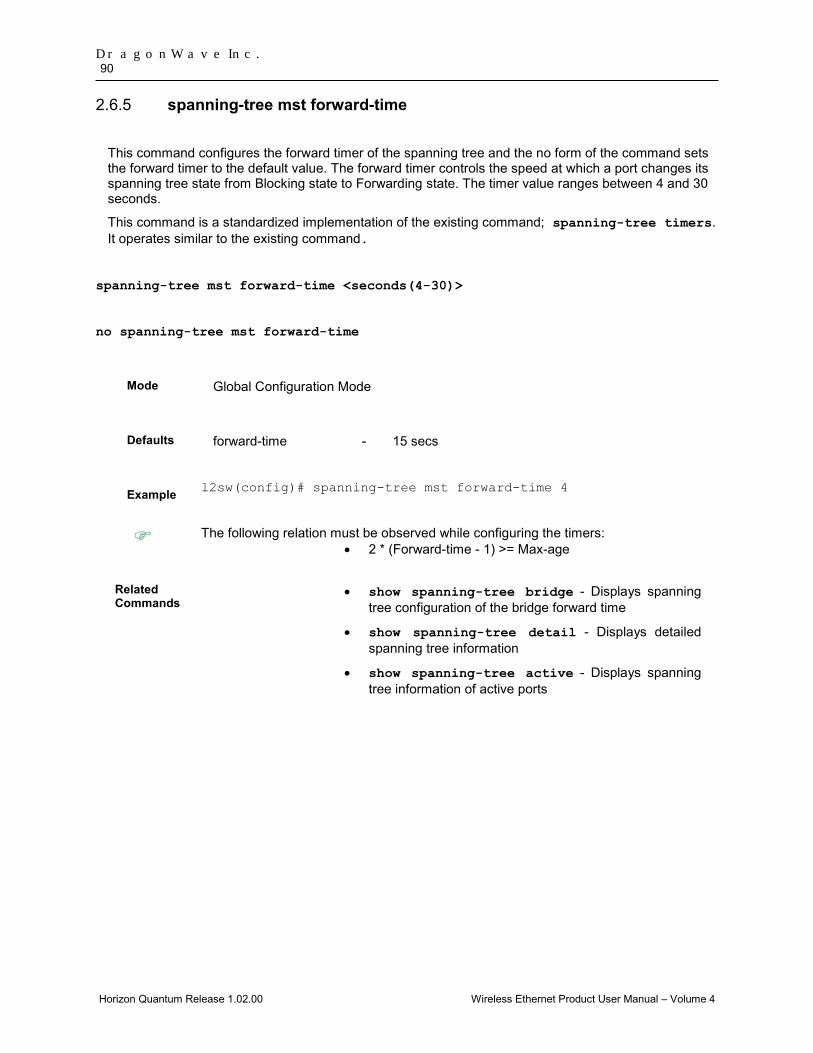
DragonWave Inc. 90
Horizon Quantum Release 1.02.00 Wireless Ethernet Product User Manual – Volume 4
spanning-tree mst forward-time 2.6.5
This command configures the forward timer of the spanning tree and the no form of the command sets the forward timer to the default value. The forward timer controls the speed at which a port changes its spanning tree state from Blocking state to Forwarding state. The timer value ranges between 4 and 30 seconds.
This command is a standardized implementation of the existing command; spanning-tree timers. It operates similar to the existing command.
spanning-tree mst forward-time <seconds(4-30)>
no spanning-tree mst forward-time
Mode Global Configuration Mode
Defaults forward-time - 15 secs
Example l2sw(config)# spanning-tree mst forward-time 4
The following relation must be observed while configuring the timers: • 2 * (Forward-time - 1) >= Max-age
Related Commands
• show spanning-tree bridge - Displays spanning tree configuration of the bridge forward time
• show spanning-tree detail - Displays detailed spanning tree information
• show spanning-tree active - Displays spanning tree information of active ports
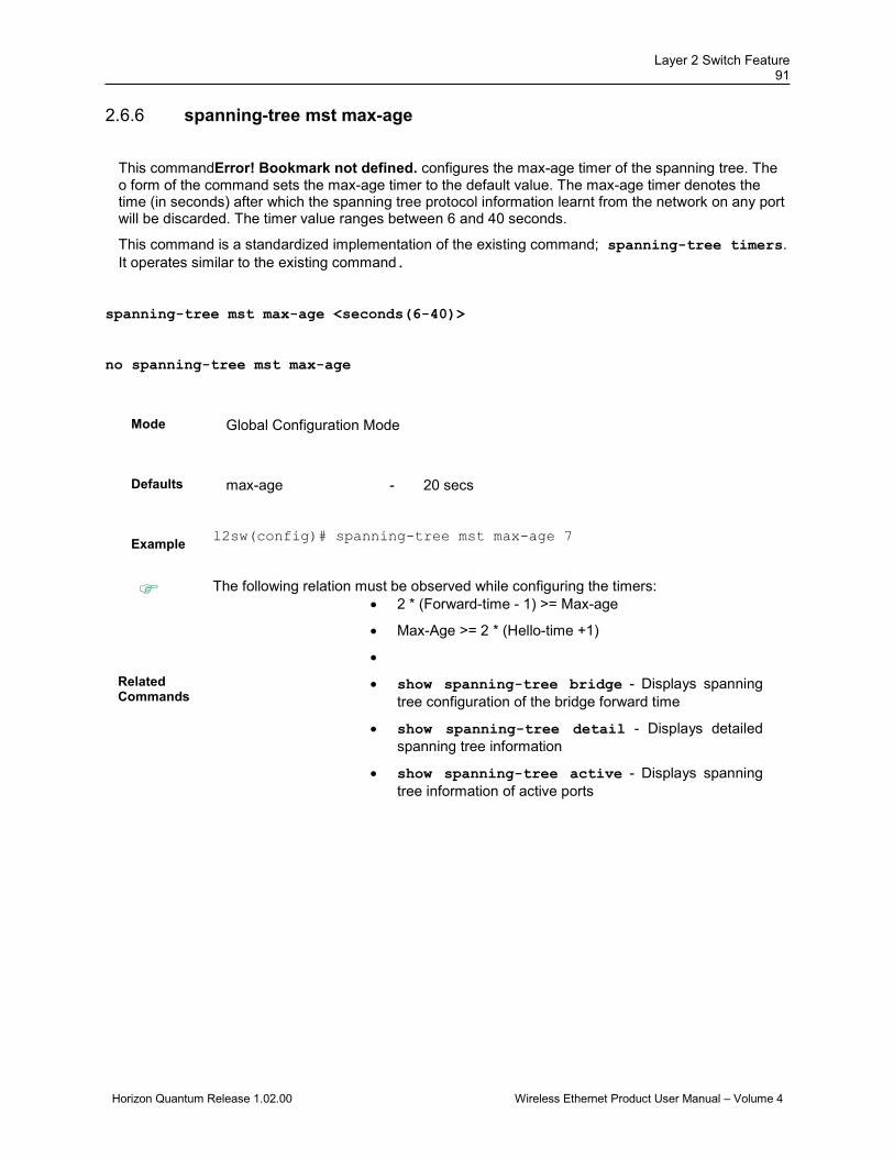
Layer 2 Switch Feature 91
Horizon Quantum Release 1.02.00 Wireless Ethernet Product User Manual – Volume 4
spanning-tree mst max-age 2.6.6
This commandError! Bookmark not defined. configures the max-age timer of the spanning tree. The o form of the command sets the max-age timer to the default value. The max-age timer denotes the time (in seconds) after which the spanning tree protocol information learnt from the network on any port will be discarded. The timer value ranges between 6 and 40 seconds.
This command is a standardized implementation of the existing command; spanning-tree timers. It operates similar to the existing command.
spanning-tree mst max-age <seconds(6-40)>
no spanning-tree mst max-age
Mode Global Configuration Mode
Defaults max-age - 20 secs
Example l2sw(config)# spanning-tree mst max-age 7
The following relation must be observed while configuring the timers: • 2 * (Forward-time - 1) >= Max-age
• Max-Age >= 2 * (Hello-time +1)
• Related Commands
• show spanning-tree bridge - Displays spanning tree configuration of the bridge forward time
• show spanning-tree detail - Displays detailed spanning tree information
• show spanning-tree active - Displays spanning tree information of active ports

DragonWave Inc. 92
Horizon Quantum Release 1.02.00 Wireless Ethernet Product User Manual – Volume 4
name 2.6.7This command configures the name for the MST region.
The no form of this command resets the name to its default value.
The name is unique and used to identify the specific MST region. Each MST region contains multiple spanning tree instances and runs special instance of spanning tree known as IST to disseminate STP topology information for other STP instances.
name <string(optional max Length)>
no name
Mode MSTP Configuration mode
Defaults Same as that of the base MAC address of the switch.
Example l2sw(config-mst)#name regionone
Related Command
• base-mac - Configures the base unicast MAC address of the switch in the NVRAM.
• show spanning-tree mst configuration - Displays multiple spanning tree instance related information.
revision 2.6.8This command configures the revision number for the MST region. This value ranges between 0 and 65535.
The no form of this command resets the revision number to its default value. revision <value(0-65535)>
no revision
Mode MSTP Configuration mode
Defaults 0
Example l2sw(config-mst)#revision 100
Related Command
• show spanning-tree mst configuration - Displays multiple spanning tree instance related information.
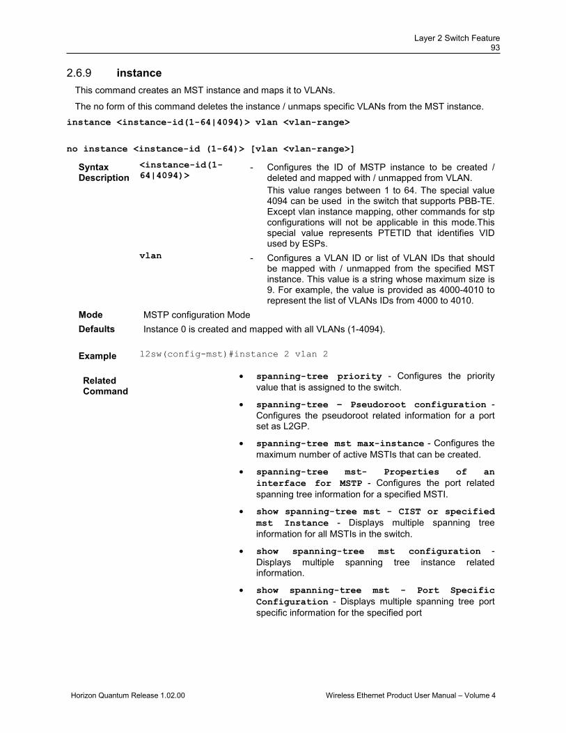
Layer 2 Switch Feature 93
Horizon Quantum Release 1.02.00 Wireless Ethernet Product User Manual – Volume 4
instance 2.6.9This command creates an MST instance and maps it to VLANs.
The no form of this command deletes the instance / unmaps specific VLANs from the MST instance. instance <instance-id(1-64|4094)> vlan <vlan-range>
no instance <instance-id (1-64)> [vlan <vlan-range>]
Syntax Description
<instance-id(1-64|4094)>
- Configures the ID of MSTP instance to be created / deleted and mapped with / unmapped from VLAN. This value ranges between 1 to 64. The special value 4094 can be used in the switch that supports PBB-TE. Except vlan instance mapping, other commands for stp configurations will not be applicable in this mode.This special value represents PTETID that identifies VID used by ESPs.
vlan - Configures a VLAN ID or list of VLAN IDs that should be mapped with / unmapped from the specified MST instance. This value is a string whose maximum size is 9. For example, the value is provided as 4000-4010 to represent the list of VLANs IDs from 4000 to 4010.
Mode MSTP configuration Mode Defaults Instance 0 is created and mapped with all VLANs (1-4094).
Example l2sw(config-mst)#instance 2 vlan 2
Related Command
• spanning-tree priority - Configures the priority value that is assigned to the switch.
• spanning-tree – Pseudoroot configuration - Configures the pseudoroot related information for a port set as L2GP.
• spanning-tree mst max-instance - Configures the maximum number of active MSTIs that can be created.
• spanning-tree mst- Properties of an interface for MSTP - Configures the port related spanning tree information for a specified MSTI.
• show spanning-tree mst - CIST or specified mst Instance - Displays multiple spanning tree information for all MSTIs in the switch.
• show spanning-tree mst configuration - Displays multiple spanning tree instance related information.
• show spanning-tree mst - Port Specific Configuration - Displays multiple spanning tree port specific information for the specified port
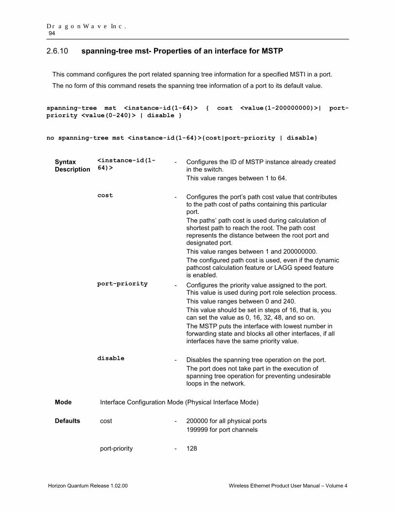
DragonWave Inc. 94
Horizon Quantum Release 1.02.00 Wireless Ethernet Product User Manual – Volume 4
spanning-tree mst- Properties of an interface for MSTP 2.6.10
This command configures the port related spanning tree information for a specified MSTI in a port.
The no form of this command resets the spanning tree information of a port to its default value.
spanning-tree mst <instance-id(1-64)> { cost <value(1-200000000)>| port-priority <value(0-240)> | disable }
no spanning-tree mst <instance-id(1-64)>{cost|port-priority | disable}
Syntax Description
<instance-id(1-64)>
- Configures the ID of MSTP instance already created in the switch. This value ranges between 1 to 64.
cost - Configures the port’s path cost value that contributes to the path cost of paths containing this particular port. The paths’ path cost is used during calculation of shortest path to reach the root. The path cost represents the distance between the root port and designated port. This value ranges between 1 and 200000000. The configured path cost is used, even if the dynamic pathcost calculation feature or LAGG speed feature is enabled.
port-priority - Configures the priority value assigned to the port. This value is used during port role selection process. This value ranges between 0 and 240. This value should be set in steps of 16, that is, you can set the value as 0, 16, 32, 48, and so on. The MSTP puts the interface with lowest number in forwarding state and blocks all other interfaces, if all interfaces have the same priority value.
disable - Disables the spanning tree operation on the port. The port does not take part in the execution of spanning tree operation for preventing undesirable loops in the network.
Mode Interface Configuration Mode (Physical Interface Mode)
Defaults cost - 200000 for all physical ports 199999 for port channels
port-priority - 128

Layer 2 Switch Feature 95
Horizon Quantum Release 1.02.00 Wireless Ethernet Product User Manual – Volume 4
disable - Spanning tree operation is enabled in the port.
Example l2sw(config-if)#spanning-tree mst 2 cost 4000 l2sw(config-if)#spanning-tree mst 1 port-priority 32 l2sw(config-if)#spanning-tree mst 2 disable
This command can be executed successfully, only if the spanning tree functionality is not shutdown in the switch. The type of spanning tree mode should be set as mst.
Related Command
• shutdown spanning-tree - Shuts down spanning tree functionality in the switch.
• spanning-tree mode - Sets the type of spanning tree to be executed, enables spanning tree operation and starts spanning tree functionality in the switch.
• spanning-tree pathcost dynamic - Enables dynamic pathcost calculation feature in the switch.
• instance - Creates an MST instance and maps it to VLANs.
• show spanning-tree - Summary, Blockedports, Pathcost, redundancy - Displays spanning tree related information available in the switch for the current STP enabled in the switch.
• show spanning-tree detail - Displays detailed spanning tree related information of the switch and all ports enabled in the switch.
• show spanning-tree active - Displays spanning tree related information available in the switch for the current STP enabled in the switch.
• show spanning-tree interface - Displays the port related spanning tree information for the specified interface.
• show spanning-tree mst - CIST or specified mst Instance - Displays multiple spanning tree information for all MSTIs in the switch.

DragonWave Inc. 96
Horizon Quantum Release 1.02.00 Wireless Ethernet Product User Manual – Volume 4
spanning-tree mst hello-time 2.6.11This command configures the hello time for an interface.
The no form of this command resets the hello time to its default value.
The hello time represents the time interval (in seconds) between two successive configuration BPDUs generated by the switch on the port. This value is either 1 or 2 seconds. This value is applied to all active MSTIs on the interface.
spanning-tree mst hello-time<value(1-2)>
no spanning-tree mst hello-time
Mode Interface Configuration Mode (Physical Interface Mode)
Defaults 2 seconds
Example l2sw(config-if)#spanning-tree mst hello-time 1
This command can be executed successfully, only if the spanning tree functionality is not shutdown in the switch. The type of spanning tree mode should be set as mst.
Related Command
• shutdown spanning-tree - Shuts down spanning tree functionality in the switch.
• spanning-tree mode - Sets the type of spanning tree to be executed, enables spanning tree operation and starts spanning tree functionality in the switch.
• show spanning-tree - Summary, Blockedports, Pathcost, redundancy - Displays spanning tree related information available in the switch for the current STP enabled in the switch.
• show spanning-tree detail - Displays detailed spanning tree related information of the switch and all ports enabled in the switch.
• show spanning-tree interface - Displays the port related spanning tree information for the specified interface.
• show spanning-tree root - Displays the spanning tree root information.
• show spanning-tree bridge - Displays the spanning tree bridge information.
• show spanning-tree mst - Port Specific Configuration - Displays multiple spanning tree port specific information for the specified port.
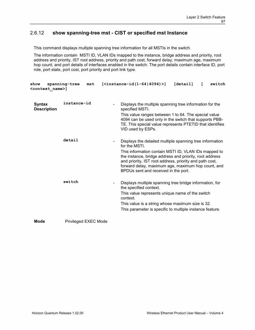
Layer 2 Switch Feature 97
Horizon Quantum Release 1.02.00 Wireless Ethernet Product User Manual – Volume 4
show spanning-tree mst - CIST or specified mst Instance 2.6.12
This command displays multiple spanning tree information for all MSTIs in the switch.
The information contain MSTI ID, VLAN IDs mapped to the instance, bridge address and priority, root address and priority, IST root address, priority and path cost, forward delay, maximum age, maximum hop count, and port details of interfaces enabled in the switch. The port details contain interface ID, port role, port state, port cost, port priority and port link type.
show spanning-tree mst [<instance-id(1-64|4094)>] [detail] [ switch <context_name>]
Syntax Description
instance-id - Displays the multiple spanning tree information for the specified MSTI. This value ranges between 1 to 64. The special value 4094 can be used only in the switch that supports PBB-TE. This special value represents PTETID that identifies VID used by ESPs.
detail - Displays the detailed multiple spanning tree information for the MSTI. This information contain MSTI ID, VLAN IDs mapped to the instance, bridge address and priority, root address and priority, IST root address, priority and path cost, forward delay, maximum age, maximum hop count, and BPDUs sent and received in the port.
switch - Displays multiple spanning tree bridge information, for the specified context. This value represents unique name of the switch context. This value is a string whose maximum size is 32. This parameter is specific to multiple instance feature.
Mode Privileged EXEC Mode

DragonWave Inc. 98
Horizon Quantum Release 1.02.00 Wireless Ethernet Product User Manual – Volume 4
Example Single Instance: l2sw# show spanning-tree mst 1 ## MST01 Vlans mapped: 2 Bridge Address 00:01:02:03:04:11 Priority 32768 Root Address 00:01:02:03:04:11 Priority 32768 Root this switch for MST01 Interface Role Sts Cost Prio.Nbr Type --------- ---- --- ---- -------- ---- Gi0/1 Master Forwarding 200000 128.1 SharedLan l2sw# show spanning-tree mst 1 detail ## MST01 Vlans mapped: 2 Bridge Address 00:01:02:03:04:11 Priority 32768 Root Address 00:01:02:03:04:11 Priority 32768 Root this switch for MST01 Gi0/1 of MST01 is Master , Forwarding Port info port id 128.1 priority 128 cost 200000 Designated root address 00:01:02:03:04:11 priority 32768 cost 0 Designated bridge address 00:01:02:03:04:11 priority 32768 port id 128.1 Multiple Instance: l2sw# show spanning-tree mst 1 Switch – default ## MST01 Vlans mapped: 2 Bridge Address 00:01:02:03:04:11 Priority 32768 Root Address 00:01:02:03:04:11 Priority 32768 Root this switch for MST01 Interface Role Sts Cost Prio.Nbr Type --------- ---- --- ---- -------- ---- Gi0/1 Master Forwarding 200000 128.1 SharedLan
This command can be executed successfully, only if the spanning tree functionality is not shutdown in the switch. The type of spanning tree mode should be set as mst.

Layer 2 Switch Feature 99
Horizon Quantum Release 1.02.00 Wireless Ethernet Product User Manual – Volume 4
Related Commands
• shutdown spanning-tree - Shuts down spanning tree functionality in the switch.
• spanning-tree - Enables the spanning tree operation in the switch for the selected spanning tree mode.
• spanning-tree mode - Sets the type of spanning tree to be executed, enables spanning tree operation and starts spanning tree functionality in the switch.
• spanning-tree timers - Sets the spanning tree timers such as hello time, that are used for controlling the transmission of BPDUs during the computation of loop free topology.
• clear spanning-tree counters - Deletes all bridge and port level spanning tree statistics information.
• spanning-tree priority - Configures the priority value that is assigned to the switch.
• spanning-tree - Properties of an interface - Configures the port related spanning tree information for all kinds of STPs.
• spanning-tree layer2-gateway-port - Configures a port to operate as a L2GP.
• spanning-tree – Pseudoroot configuration - Configures the pseudoroot related information for a port set as L2GP.
• spanning-tree mst max-hops - Configures the maximum number of hops permitted in the MST.
• instance - Creates an MST instance and maps it to VLANs.
• spanning-tree mst- Properties of an interface for MSTP - Configures the port related spanning tree information for a specified MSTI.
• base-mac - Configures the base unicast MAC address of the switch in the NVRAM.
• shutdown - physical/VLAN/port-channel/tunnel Interface - Disables a physical interface / VLAN interface / port-channel interface / tunnel interface / OOB interface.
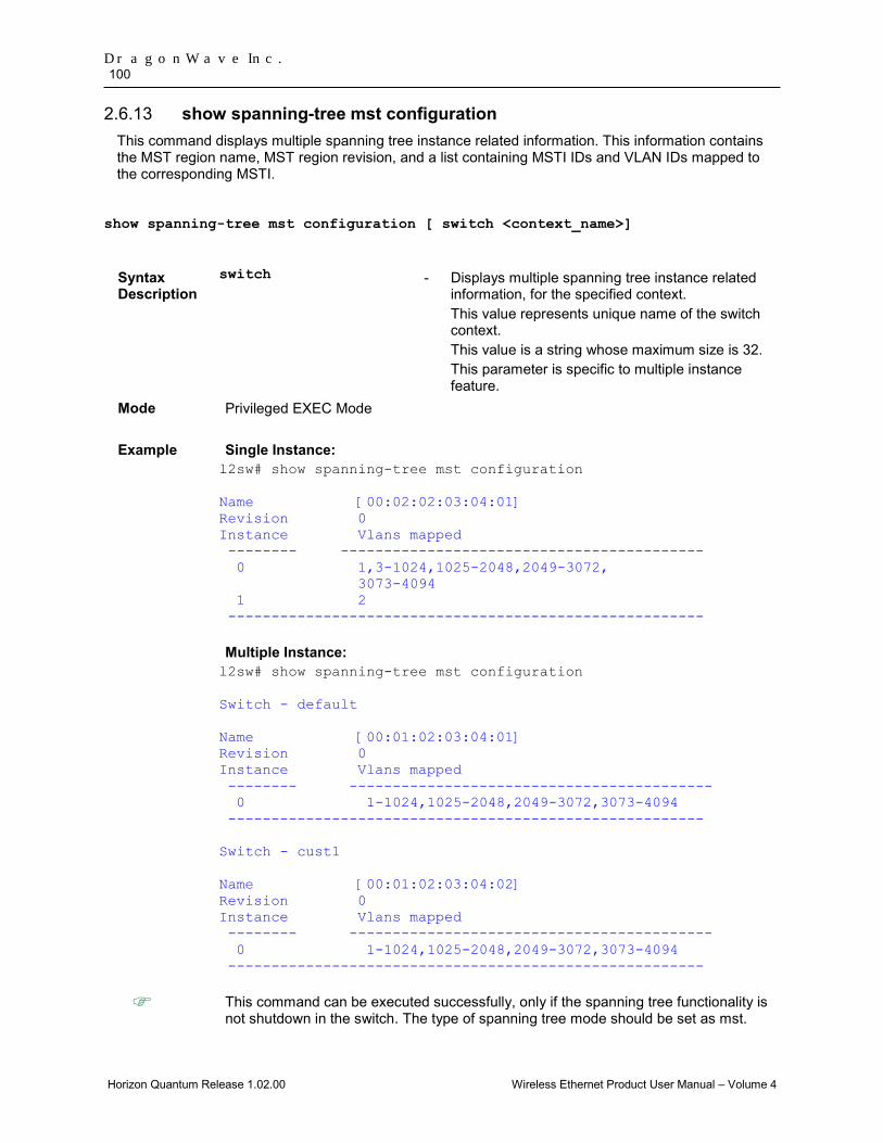
DragonWave Inc. 100
Horizon Quantum Release 1.02.00 Wireless Ethernet Product User Manual – Volume 4
show spanning-tree mst configuration 2.6.13This command displays multiple spanning tree instance related information. This information contains the MST region name, MST region revision, and a list containing MSTI IDs and VLAN IDs mapped to the corresponding MSTI.
show spanning-tree mst configuration [ switch <context_name>]
Syntax Description
switch - Displays multiple spanning tree instance related information, for the specified context. This value represents unique name of the switch context. This value is a string whose maximum size is 32. This parameter is specific to multiple instance feature.
Mode Privileged EXEC Mode
Example Single Instance: l2sw# show spanning-tree mst configuration Name [00:02:02:03:04:01] Revision 0 Instance Vlans mapped -------- ------------------------------------------ 0 1,3-1024,1025-2048,2049-3072, 3073-4094 1 2 ------------------------------------------------------- Multiple Instance: l2sw# show spanning-tree mst configuration Switch - default Name [00:01:02:03:04:01] Revision 0 Instance Vlans mapped -------- ------------------------------------------ 0 1-1024,1025-2048,2049-3072,3073-4094 ------------------------------------------------------- Switch - cust1 Name [00:01:02:03:04:02] Revision 0 Instance Vlans mapped -------- ------------------------------------------ 0 1-1024,1025-2048,2049-3072,3073-4094 -------------------------------------------------------
This command can be executed successfully, only if the spanning tree functionality is not shutdown in the switch. The type of spanning tree mode should be set as mst.
Layer 2 Switch Feature 101
Horizon Quantum Release 1.02.00 Wireless Ethernet Product User Manual – Volume 4
Related Commands
• shutdown spanning-tree - Shuts down spanning tree functionality in the switch.
• spanning-tree mode - Sets the type of spanning tree to be executed, enables spanning tree operation and starts spanning tree functionality in the switch.
• name - Configures the name for the MST region.
• revision - Configures the revision number for the MST region.
• instance - Creates an MST instance and maps it to VLANs.
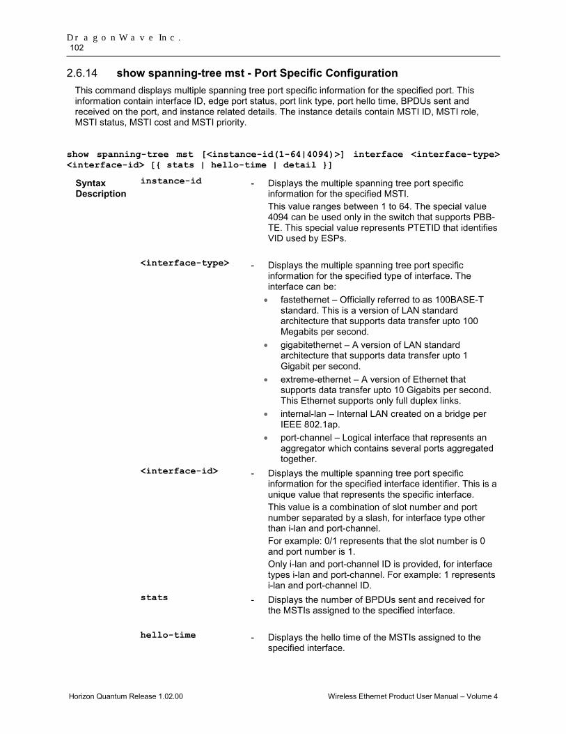
DragonWave Inc. 102
Horizon Quantum Release 1.02.00 Wireless Ethernet Product User Manual – Volume 4
show spanning-tree mst - Port Specific Configuration 2.6.14This command displays multiple spanning tree port specific information for the specified port. This information contain interface ID, edge port status, port link type, port hello time, BPDUs sent and received on the port, and instance related details. The instance details contain MSTI ID, MSTI role, MSTI status, MSTI cost and MSTI priority.
show spanning-tree mst [<instance-id(1-64|4094)>] interface <interface-type> <interface-id> [{ stats | hello-time | detail }]
Syntax Description
instance-id - Displays the multiple spanning tree port specific information for the specified MSTI. This value ranges between 1 to 64. The special value 4094 can be used only in the switch that supports PBB-TE. This special value represents PTETID that identifies VID used by ESPs.
<interface-type> - Displays the multiple spanning tree port specific information for the specified type of interface. The interface can be: • fastethernet – Officially referred to as 100BASE-T
standard. This is a version of LAN standard architecture that supports data transfer upto 100 Megabits per second.
• gigabitethernet – A version of LAN standard architecture that supports data transfer upto 1 Gigabit per second.
• extreme-ethernet – A version of Ethernet that supports data transfer upto 10 Gigabits per second. This Ethernet supports only full duplex links.
• internal-lan – Internal LAN created on a bridge per IEEE 802.1ap.
• port-channel – Logical interface that represents an aggregator which contains several ports aggregated together.
<interface-id> - Displays the multiple spanning tree port specific information for the specified interface identifier. This is a unique value that represents the specific interface. This value is a combination of slot number and port number separated by a slash, for interface type other than i-lan and port-channel. For example: 0/1 represents that the slot number is 0 and port number is 1. Only i-lan and port-channel ID is provided, for interface types i-lan and port-channel. For example: 1 represents i-lan and port-channel ID.
stats - Displays the number of BPDUs sent and received for the MSTIs assigned to the specified interface.
hello-time - Displays the hello time of the MSTIs assigned to the specified interface.
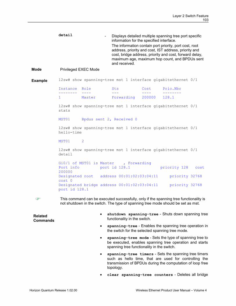
Layer 2 Switch Feature 103
Horizon Quantum Release 1.02.00 Wireless Ethernet Product User Manual – Volume 4
detail - Displays detailed multiple spanning tree port specific
information for the specified interface. The information contain port priority, port cost, root address, priority and cost, IST address, priority and cost, bridge address, priority and cost, forward delay, maximum age, maximum hop count, and BPDUs sent and received.
Mode Privileged EXEC Mode
Example l2sw# show spanning-tree mst 1 interface gigabitethernet 0/1 Instance Role Sts Cost Prio.Nbr -------- ---- --- ---- -------- 1 Master Forwarding 200000 128.1 l2sw# show spanning-tree mst 1 interface gigabitethernet 0/1 stats MST01 Bpdus sent 2, Received 0 l2sw# show spanning-tree mst 1 interface gigabitethernet 0/1 hello-time MST01 2 l2sw# show spanning-tree mst 1 interface gigabitethernet 0/1 detail Gi0/1 of MST01 is Master , Forwarding Port info port id 128.1 priority 128 cost 200000 Designated root address 00:01:02:03:04:11 priority 32768 cost 0 Designated bridge address 00:01:02:03:04:11 priority 32768 port id 128.1
This command can be executed successfully, only if the spanning tree functionality is not shutdown in the switch. The type of spanning tree mode should be set as mst.
Related Commands
• shutdown spanning-tree - Shuts down spanning tree functionality in the switch.
• spanning-tree - Enables the spanning tree operation in the switch for the selected spanning tree mode.
• spanning-tree mode - Sets the type of spanning tree to be executed, enables spanning tree operation and starts spanning tree functionality in the switch.
• spanning-tree timers - Sets the spanning tree timers such as hello time, that are used for controlling the transmission of BPDUs during the computation of loop free topology.
• clear spanning-tree counters - Deletes all bridge
DragonWave Inc. 104
Horizon Quantum Release 1.02.00 Wireless Ethernet Product User Manual – Volume 4
and port level spanning tree statistics information.
• spanning-tree priority - Configures the priority value that is assigned to the switch.
• spanning-tree - Properties of an interface - Configures the port related spanning tree information for all kinds of STPs.
• spanning-tree layer2-gateway-port – Configures a port to operate as a L2GP.
• spanning-tree – Pseudoroot configuration - Configures the pseudoroot related information for a port set as L2GP.
• spanning-tree mst max-hops - Configures the maximum number of hops permitted in the MST.
• instance - Creates an MST instance and maps it to VLANs.
• spanning-tree mst hello-time - Configures the hello time for an interface that is enabled.
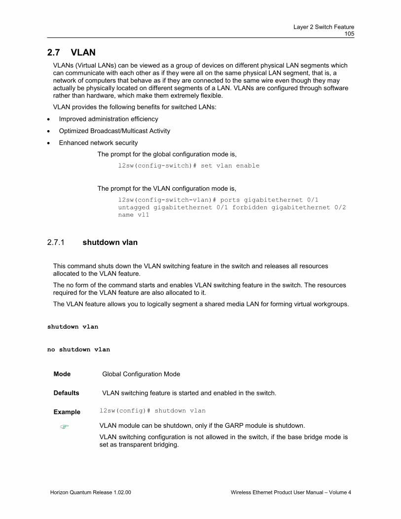
Layer 2 Switch Feature 105
Horizon Quantum Release 1.02.00 Wireless Ethernet Product User Manual – Volume 4
2.7 VLAN VLANs (Virtual LANs) can be viewed as a group of devices on different physical LAN segments which can communicate with each other as if they were all on the same physical LAN segment, that is, a network of computers that behave as if they are connected to the same wire even though they may actually be physically located on different segments of a LAN. VLANs are configured through software rather than hardware, which make them extremely flexible.
VLAN provides the following benefits for switched LANs:
• Improved administration efficiency
• Optimized Broadcast/Multicast Activity
• Enhanced network security
The prompt for the global configuration mode is,
l2sw(config-switch)# set vlan enable
The prompt for the VLAN configuration mode is,
l2sw(config-switch-vlan)# ports gigabitethernet 0/1 untagged gigabitethernet 0/1 forbidden gigabitethernet 0/2 name vl1
shutdown vlan 2.7.1
This command shuts down the VLAN switching feature in the switch and releases all resources allocated to the VLAN feature.
The no form of the command starts and enables VLAN switching feature in the switch. The resources required for the VLAN feature are also allocated to it.
The VLAN feature allows you to logically segment a shared media LAN for forming virtual workgroups.
shutdown vlan
no shutdown vlan
Mode Global Configuration Mode
Defaults VLAN switching feature is started and enabled in the switch.
Example l2sw(config)# shutdown vlan
VLAN module can be shutdown, only if the GARP module is shutdown.
VLAN switching configuration is not allowed in the switch, if the base bridge mode is set as transparent bridging.

DragonWave Inc. 106
Horizon Quantum Release 1.02.00 Wireless Ethernet Product User Manual – Volume 4
Related Commands
• set vlan - Globally enables / disables VLAN feature in the switch (that is the status of the VLAN feature is configured for all ports of the switch).
• vlan - Creates a VLAN in the l2sw and enters into the config-VLAN mode in which VLAN specific configurations are done.
• mac-address-table aging-time - Configures the timeout period (in seconds) for aging out dynamically learned forwarding information entry and static entry in the MAC address table.
• clear vlan statistics - Clears VLAN counters that maintain statistics information on a per VLAN basis. The counter is cleared for all available VLANs or for the specified VLAN.
• switchport pvid - Configures the PVID on the specified port.
• switchport acceptable-frame-type - Configures the type of VLAN dependant BPDU frames such as GMRP BPDU, that the port should accept during the VLAN membership configuration.
• switchport priority default - Configures the default ingress user priority for a port.
• switchport mode - Configures the mode of operation for a switch port.
• debug vlan - Enables the tracing of the VLAN submodule as per the configured debug levels.
• show vlan - Displays VLAN entry related information of all active VLANs and VLANs (that are not active) for which the port details are configured.
• show vlan device info - Displays the VLAN global information that is applicable to all VLANs created in the switch / all contexts.
• show vlan port config - Displays the VLAN related port specific information for all interfaces available in the switch / all contexts.
• show vlan counters - Displays the VLAN traffic statistics details for all VLANs (for which the member port details are configured) available in the switch / all contexts.
• show vlan statistics - Displays the unicast / broadcast statistics details of all active VLANs and VLANs (that are not active) for which the port details are configured.
• show mac-address-table - Displays all static / dynamic unicast and multicast MAC entries created in the MAC address table.
• show mac-address-table count - Displays the total number of static / dynamic unicast and multicast MAC address entries created in the FDB table.
• show mac-address-table static unicast - Displays all static unicast MAC address entries created in the FDB table.
• show mac-address-table static multicast - Displays the static multicast MAC address entries created in the FDB table.
• show mac-address-table dynamic unicast - Displays all dynamically learnt unicast entries from the MAC address table.
• show mac-address-table dynamic multicast - Displays all dynamically learnt multicast entries from the MAC address table.

Layer 2 Switch Feature 107
Horizon Quantum Release 1.02.00 Wireless Ethernet Product User Manual – Volume 4
• show mac-address-table aging-time - Displays the ageing time configured for the MAC address table.
• show vlan learning params - Displays the VLAN learning parameter details for all active VLANs and VLANs (that are not active) for which the port details are configured, available in all contexts / in the switch.
set vlan 2.7.2This command globally enables / disables VLAN feature in the switch. The VLAN feature allows you to logically segment a shared media LAN for forming virtual workgroups.
set vlan { enable | disable }
Syntax Description
enable - Enables VLAN feature on all ports of the switch.
disable - Disables VLAN feature on all ports of the switch.
Mode Global Configuration Mode
Defaults enable
Example l2sw(config)# set vlan disable
The VLAN feature can be disabled on all ports of the switch, only if GVRP and GMRP features are disabled on all ports of the switch.
The VLAN feature cannot be configured in the switch, if the base bridge mode is set as transparent bridging.
VLAN feature can be enabled / disabled in the switch, only if the VLAN switching feature is started and enabled in the switch.
This command is available only on simulation environment. Not available on target platforms.
Related Commands
• no shutdown vlan - Starts and enables VLAN switching feature in the switch.
• show vlan device info - Displays the VLAN global information that is applicable to all VLANs created in the switch / all contexts

DragonWave Inc. 108
Horizon Quantum Release 1.02.00 Wireless Ethernet Product User Manual – Volume 4
vlan 2.7.3This command creates a VLAN in the l2sw and enters into the config-VLAN mode in which VLAN specific configurations are done. This command directly enters into the config-VLAN mode for the specified VLAN, if the VLAN is already created. The created VLAN is identified using a unique VLAN ID whose value ranges from 1 to 4094.
The no form of the command deletes the existing VLAN and its corresponding configurations from the ISS.
vlan <vlan-id(1-4094)>
no vlan <vlan-id(1-4094)
Mode Global Configuration Mode
Defaults VLAN 1 is already created and exists in the ISS.
Example l2sw(config)# vlan 4
• The Native VLAN (VLAN 1) created by default cannot be deleted using the no form of the command.
• The creation of new VLAN and configuration of existing VLAN can be done, only if the VLAN switching feature is started and enabled in the switch.
Related Command
• no shutdown vlan - Starts and enables VLAN switching feature in the switch.
• interface vlan <vlan-id> - Creates an L3 VLAN interface. An L3 VLAN interface is a VLAN that is mapped to an IP interface and assigned an IP address.
• show vlan - Displays VLAN entry related information of all active VLANs and VLANs (that are not active) for which the port details are configured.
mac-address-table static unicast 2.7.4
This command configures a static unicast MAC address in the forwarding database. The no form of the command deletes a configured static Unicast MAC address from the forwarding database.
Note: More than one egress ports (AllowedToGoTo ports) for a static unicast entry is not supported.
mac-address-table static unicast <aa:aa:aa:aa:aa:aa> vlan <vlan-id(1-4094)> [{recv-port <ifXtype> <ifnum> }] interface ([<interface-type> <0/a-b, 0/c, ...>] [<interface-type> <0/a-b, 0/c, ...>] [port-channel <a,b,c-d>]) [connection-identifier <ucast_mac>] [status { permanent | deleteOnReset | deleteOnTimeout }]
no mac-address-table static unicast <aa:aa:aa:aa:aa:aa> vlan <vlan-id(1-4094)> [{recv-port <ifXtype> <ifnum>}]
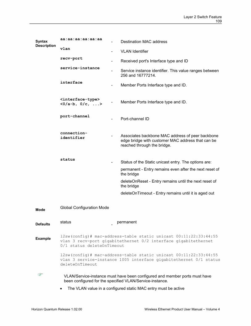
Layer 2 Switch Feature 109
Horizon Quantum Release 1.02.00 Wireless Ethernet Product User Manual – Volume 4
Syntax Description
aa:aa:aa:aa:aa:aa - Destination MAC address
vlan - VLAN Identifier
recv-port - Received port's Interface type and ID
service-instance - Service instance identifier. This value ranges between
256 and 16777214. interface
- Member Ports Interface type and ID.
<interface-type> <0/a-b, 0/c, ...> - Member Ports Interface type and ID.
port-channel
- Port-channel ID
connection-identifier - Associates backbone MAC address of peer backbone
edge bridge with customer MAC address that can be reached through the bridge.
status
- Status of the Static unicast entry. The options are:
permanent - Entry remains even after the next reset of the bridge
deleteOnReset - Entry remains until the next reset of the bridge
deleteOnTimeout - Entry remains until it is aged out
Mode Global Configuration Mode
Defaults status
- permanent
Example l2sw(config)# mac-address-table static unicast 00:11:22:33:44:55 vlan 3 recv-port gigabitethernet 0/2 interface gigabitethernet 0/1 status deleteOnTimeout l2sw(config)# mac-address-table static unicast 00:11:22:33:44:55 vlan 3 service-instance 1005 interface gigabitethernet 0/1 status deleteOnTimeout
VLAN/Service-instance must have been configured and member ports must have been configured for the specified VLAN/Service-instance.
• The VLAN value in a configured static MAC entry must be active

DragonWave Inc. 110
Horizon Quantum Release 1.02.00 Wireless Ethernet Product User Manual – Volume 4
• The Egress Port value in a configured static MAC entry must be a member of the configured VLAN
• The Receive Port value in a configured static MAC entry must be a member of the configured VLAN
• Receive Port cannot be an Egress port in a configured static MAC entry
Related Commands
• show mac-address-table static unicast - Displays the statically configured unicast address from the MAC address table.
• mac-address-table static multicast - Configures a static multicast MAC address in the forwarding database.
• vlan - Configures a VLAN in the switch and is also used to enter in to the config-VLAN mode.
mac-address-table static unicast – Transparent Bridging Mode 2.7.5
This command configures a static unicast MAC address in the forwarding database in transparent bridging mode in order to control unicast packets to be processed. Only the unicast packets having the configured value are processed.
The no form of the command deletes the configured static unicast address from the forwarding database.
mac-address-table static unicast <aa:aa:aa:aa:aa:aa> [recv-port <interface-type> <interface-id>] interface ([<interface-type> <0/a-b,0/c,...>] [<interface-type> <0/a-b,0/c,...>] [port-channel <a,b,c-d>]) [status { permanent | deleteOnReset | deleteOnTimeout }]
no mac-address-table static unicast <aa:aa:aa:aa:aa:aa> [recv-port <interface-type> <interface-id>]
Syntax Description
<aa:aa:aa:aa:aa:aa> - Configures the unicast destination MAC address. The received packets having the specified MAC address are processed.
recv-port - Configures the receive port's details. The unicast packets received only on this specified port are processed. The details to be provided are: • <interface-type> - Sets the type of interface. The
interface can be:
1. fastethernet – Officially referred to as 100BASE-T standard. This is a version of LAN standard architecture that supports data transfer up to 100 Megabits per second.
2. gigabitethernet – A version of LAN standard

Layer 2 Switch Feature 111
Horizon Quantum Release 1.02.00 Wireless Ethernet Product User Manual – Volume 4
architecture that supports data transfer up to 1 Gigabit per second.
3. extreme-ethernet – A version of Ethernet that supports data transfer up to 10 Gigabits per second. This Ethernet supports only full duplex links.
4. internal-lan – Internal LAN created on a bridge per IEEE 802.1ap.
5. port-channel – Logical interface that represents an aggregator which contains several ports aggregated together.
• <interface-id> - Sets the interface identifier. This is a unique value that represents the specific interface. This value is a combination of slot number and port number separated by a slash, for interface type other than internal-lan and port-channel. Only i-lan or port-channel ID is provided, for interface types internal-lan and port-channel.
interface - Configures the member ports details. The unicast packets received on the specified receive ports and having the specified unicast destination MAC address are forwarded through these member ports. The details to be provided are: • <interface-type> - Sets the type of interface. The
interface can be:
1. fastethernet – Officially referred to as 100BASE-T standard. This is a version of LAN standard architecture that supports data transfer up to 100 Megabits per second.
2. gigabitethernet – A version of LAN standard architecture that supports data transfer up to 1 Gigabit per second.
3. extreme-ethernet – A version of Ethernet that supports data transfer up to 10 Gigabits per second. This Ethernet supports only full duplex links.
4. internal-lan – Internal LAN created on a bridge per IEEE 802.1ap.
5. port-channel – Logical interface that represents an aggregator which contains several ports aggregated together.
• <0/a-b, 0/c, ...> - Sets the list of interfaces or a specific interface identifier. This value is a combination of slot number and port number separated by a slash, for interface type other than internal-lan and port-channel. Only i-lan or port-channel ID is provided, for interface types internal-lan and port-channel. Use comma as a separator without space while configuring list of interfaces.

DragonWave Inc. 112
Horizon Quantum Release 1.02.00 Wireless Ethernet Product User Manual – Volume 4
Example: 0/1,0/3 or 1,3.
• port-channel - Sets the list of port channel interfaces or a specific port channel identifier. Use comma as a separator without space while configuring list of interfaces. Example: 1,3.
status - Configures the status of the static unicast entry. The
options are: • permanent - The static unicast entry resides in the
switch, even after restarting the switch.
• deleteOnReset - The static unicast entry is deleted, once the switch is restart.
• deleteOnTimeout - The static unicast entry is deleted once the MAC address table aging timer expires.
Mode Global Configuration Mode
Defaults status - permanent
Example l2sw(config)# mac-address-table static unicast 00:11:22:33:44:55
recv-port gigabitethernet 0/3 interface gigabitethernet 0/2 status deleteOnTimeout
• This command is applicable only if the base bridge mode is set as transparent bridging.
• The interface gigabitethernet 0/1 cannot be set as member port or receive port in the static entry, as it is configured as a router port in transparent bridging mode.
• The same interface cannot be configured as both ingress port (receive port) and egress port (member port). The port can act only as ingress or as egress.
• If the receive port is configured in the created static unicast MAC address entry, then that entry can be deleted only if the receive port details are exactly mentioned in the no form of the command.
• Only one static unicast MAC address entry is allowed in the switch in transparent bridging mode. If any updates need to be done in the existing one, then it should be deleted and new entry should be created with new configurations.
Related Commands
• base bridge-mode dot1d-bridge - Configures the VLAN operation mode as transparent bridging.
• mac-address-table aging-time - Configures the timeout period (in seconds) for aging out dynamically learned forwarding information entry and static entry in the MAC address table.
• show dot1d mac-address-table - Displays all static / dynamic unicast and multicast MAC address entries created in the FDB table, when the VLAN base bridge mode is transparent bridging.
• show dot1d mac-address-table static unicast- Displays all static

Layer 2 Switch Feature 113
Horizon Quantum Release 1.02.00 Wireless Ethernet Product User Manual – Volume 4
unicast MAC address entries created in the FDB table, when the VLAN base bridge mode is transparent bridging.

DragonWave Inc. 114
Horizon Quantum Release 1.02.00 Wireless Ethernet Product User Manual – Volume 4
mac-address-table static multicast 2.7.6
This command configures a static multicast MAC address in the forwarding database.
mac-address-table static multicast <aa:aa:aa:aa:aa:aa> vlan <vlan-id(1-4094)> [{recv-port <ifXtype> <ifnum>>}] interface ([<interface-type> <0/a-b, 0/c, ...>] [<interface-type> <0/a-b, 0/c, ...>] [port-channel <a,b,c-d>]]) [forbidden-ports ([<interface-type> <0/a-b, 0/c, ...>] [<interface-type> <0/a-b, 0/c, ...>] [port-channel <a,b,c-d>]]) [status { permanent | deleteOnReset | deleteOnTimeout }]
no mac-address-table static multicast <aa:aa:aa:aa:aa:aa> vlan <vlan-id(1-4094)> [recv-port <ifXtype> <ifnum>}]
Syntax Description
aa:aa:aa:aa:aa:aa
- Multicast MAC address
vlan
- VLAN Identifier
recv-port
- Received port's Interface type and ID
service-instance
- Service instance identifier. This value ranges between 256 and 16777214.
interface
- Member Ports Interface type and ID.
<interface-type> <0/a-b, 0/c, ...> - Member Ports Interface type and ID.
port-channel - Port channel ID
forbidden-ports
- Forbidden ports interface type and ID.
<interface-type> <0/a-b, 0/c, ...>
- Forbidden ports interface type and ID.
port-channel
- Port-channel ID
Layer 2 Switch Feature 115
Horizon Quantum Release 1.02.00 Wireless Ethernet Product User Manual – Volume 4
status
- Status of the static multicast entry. The options are:
permanent - Entry remains even after the next reset of the bridge
deleteOnReset - Entry remains until the next reset of the bridge
deleteOnTimeout - Entry remains until it is aged out
Mode Global Configuration Mode
Defaults status
- permanent
Example l2sw(config)# mac-address-table static multicast 01:02:03:04:05:06 vlan 2 interface gigabitethernet 0/1
VLAN/Service-instance must have been configured and member ports must have been configured for the specified VLAN/Service-instance.
Related Command
• show mac-address-table static multicast - Displays the statically configured multicast entries.
• vlan - Configures a VLAN in the switch and is also used to enter in to the config-VLAN mode.
• service instance – Used to enter the service instance mode for performing ISID specific operations.
DragonWave Inc. 116
Horizon Quantum Release 1.02.00 Wireless Ethernet Product User Manual – Volume 4
mac address-table static mcast 2.7.7
This command configures a static multicast MAC (Media Access Control) address in the forwarding database and the no form of the command deletes a configured static multicast MAC address from the forwarding database.
This command is a complete standardized implementation of the existing command and operates similar to that of the command mac-address-table static multicast.
This feature has been included in adherence to the Industry Standard CLI syntax.
mac address-table static <mcast_mac> vlan <integer(1-4094)> ([interface <interface-type> <0/a-b,0/c,...>] [<interface-type> <0/a-b,0/c,...>][port-channel <a,b,c-d>])
no mac address-table static <mcast_mac> vlan <vlan-id(1-4094)> [interface <ifXtype> <ifnum>]
Syntax Description
mcast_mac
- Multicast MAC address.
vlan
- VLAN identifier. This value ranges between 1 and
4094.
interface
- Member Ports Interface type and ID.
<interface-type> <0/a-b, 0/c, ...> - Specifies interface type and ID of the member and
forbidden ports. port-channel
- Port-channel ID
Mode Global Configuration Mode
Example l2sw(config)# mac address-table static 01:02:03:04:05:06 vlan 2 interface gigabitethernet 0/1
VLAN/Service-instance must have been configured and member ports must have been configured for the specified VLAN/Service-instance.
Layer 2 Switch Feature 117
Horizon Quantum Release 1.02.00 Wireless Ethernet Product User Manual – Volume 4
Related Command
• show mac-address-table static multicast - Displays the statically configured multicast entries.
• vlan - Configures a VLAN in the switch and is also used to enter in to the config-VLAN mode.
• service instance – Used to enter the service instance mode for performing ISID specific operations.
mac-address-table static multicast – Transparent Bridging mode 2.7.8
This command configures a static multicast MAC address in the forwarding database in transparent bridging mode in order to control multicast packets to be processed. Only the multicast packets having the configured value are processed.
The no form of command deletes the configured static multicast MAC address from the forwarding database.
This configuration is used to filter incoming reports that can be commonly used by all multicast protocols.
mac-address-table static multicast <aa:aa:aa:aa:aa:aa> [recv-port <interface-type> <interface-id>] interface ([<interface-type> <0/a-b,0/c,...>] [<interface-type> <0/a-b,0/c,...>] [port-channel <a,b,c-d>]]) [status { permanent | deleteOnReset | deleteOnTimeout }]
no mac-address-table static multicast <aa:aa:aa:aa:aa:aa> [recv-port <interface-type> <interface-id>]
Syntax Description
<aa:aa:aa:aa:aa:aa> - Configures the multicast destination MAC address. The received packets having the specified MAC address are processed.
recv-port - Configures the receive port's details. The multicast packets received only on this specified port are processed. The details to be provided are: • <ifXtype> - Sets the type of interface. The interface
can be:
1. fastethernet – Officially referred to as 100BASE-T standard. This is a version of LAN standard architecture that supports data transfer up to 100 Megabits per second.
2. gigabitethernet – A version of LAN standard architecture that supports data transfer up to 1 Gigabit per second.
3. extreme-ethernet – A version of Ethernet that supports data transfer up to 10 Gigabits per second. This Ethernet supports only full duplex links.
DragonWave Inc. 118
Horizon Quantum Release 1.02.00 Wireless Ethernet Product User Manual – Volume 4
4. internal-lan – Internal LAN created on a bridge per IEEE 802.1ap.
5. port-channel – Logical interface that represents an aggregator which contains several ports aggregated together.
• <ifnum> - Sets the interface identifier. This is a unique value that represents the specific interface. This value is a combination of slot number and port number separated by a slash, for interface type other than internal-lan and port-channel. Only i-lan or port-channel ID is provided, for interface types internal-lan and port-channel.
interface - Configures the member ports details. The multicast
packets received on the specified receive ports and having the specified multicast destination MAC address are forwarded through these member ports. The details to be provided are: • <interface-type> - Sets the type of interface. The
interface can be:
1. fastethernet – Officially referred to as 100BASE-T standard. This is a version of LAN standard architecture that supports data transfer up to 100 Megabits per second.
2. gigabitethernet – A version of LAN standard architecture that supports data transfer up to 1 Gigabit per second.
3. extreme-ethernet – A version of Ethernet that supports data transfer up to 10 Gigabits per second. This Ethernet supports only full duplex links.
4. internal-lan – Internal LAN created on a bridge per IEEE 802.1ap.
5. port-channel – Logical interface that represents an aggregator which contains several ports aggregated together.
• <0/a-b, 0/c, ...> - Sets the list of interfaces or a specific interface identifier. This value is a combination of slot number and port number separated by a slash, for interface type other than internal-lan and port-channel. Only i-lan or port-channel ID is provided, for interface types internal-lan and port-channel. Use comma as a separator without space while configuring list of interfaces. Example: 0/1,0/3 or 1,3.
• port-channel - Sets the list of port channel interfaces or a specific port channel identifier. Use comma as a separator without space while configuring list of interfaces. Example: 1,3.

Layer 2 Switch Feature 119
Horizon Quantum Release 1.02.00 Wireless Ethernet Product User Manual – Volume 4
status - Configures the status of the static multicast entry. The options are: • permanent - The static multicast entry resides in the
switch, even after restarting the switch.
• deleteOnReset - The static multicast entry is deleted, once the switch is restart.
• deleteOnTimeout - The static multicast entry is deleted once the MAC address table aging timer expires.
Mode Global Configuration Mode
Defaults status - permanent
Example l2sw(config)# mac-address-table static multicast
01:00:5E:01:02:03interface gigabitethernet 0/2
• This command is applicable only if the base bridge mode is set as transparent bridging.
• The interface gigabitethernet 0/1 cannot be set as member port or receive port in the static entry, as it is configured as a router port in transparent bridging mode.
• The same interface cannot be configured as both ingress port (receive port) and egress port (member port). The port can act only as ingress or as egress.
• If the receive port is configured in the created static multicast MAC address entry, then that entry can be deleted only if the receive port details are exactly mentioned in the no form of the command.
• Only one static multicast MAC address entry is allowed in the switch in transparent bridging mode. If any updates need to be done in the existing one, then it should be deleted and new entry should be created with new configurations.
Related Command
• base bridge-mode dot1d-bridge - Configures the VLAN operation mode as transparent bridging.
• mac-address-table aging-time - Configures the timeout period (in seconds) for aging out dynamically learned forwarding information entry and static entry in the MAC address table.
• show dot1d mac-address-table - Displays all static / dynamic unicast and multicast MAC address entries created in the FDB table, when the VLAN base bridge mode is transparent bridging.
• show dot1d mac-address-table static multicast - Displays all static multicast MAC address entries created in the FDB table, when the VLAN base bridge mode is transparent bridging.
DragonWave Inc. 120
Horizon Quantum Release 1.02.00 Wireless Ethernet Product User Manual – Volume 4
mac-address-table aging-time 2.7.9
This command configures the timeout period (in seconds) for aging out dynamically learned forwarding information entry and static entry in the MAC address table. That is, the entry is deleted once the aging timer expires.
This timeout period value ranges from 10 to 1000000 seconds, if the switch DX260 is set as no during compilation of the exe. The value ranges from 10 to 630 seconds, if the switch DX260 is set as yes during compilation of the exe.
You should provide high value for the aging time to record dynamic entries for a longer time, if traffic is not frequent. This reduces the possibility of flooding.
The no form of the command resets the maximum age of an entry in the MAC address table to its default value.
mac-address-table aging-time <10-630 seconds>
no mac-address-table aging-time
Mode Global Configuration Mode
Defaults 300
Example l2sw(config)# mac-address-table aging-time 200
• The aging timer is applied to the static entry in the MAC address table, only if static entry status is set as deleteOnTimeout.
• The MAC address table maximum age can be configured in the switch, only if the VLAN switching feature is started and enabled in the switch.
Related Command
• mac-address-table static unicast – Transparent Bridging Mode - Configures a static unicast MAC address in the forwarding database in transparent bridging mode in order to control unicast packets to be processed.
• mac-address-table static multicast – Transparent Bridging mode - Configures a static multicast MAC address in the forwarding database in transparent bridging mode in order to control multicast packets to be processed.
• no shutdown vlan - Starts and enables VLAN switching feature in the switch.
• show mac-address-table aging-time - Displays the ageing time configured for the MAC address table.
Layer 2 Switch Feature 121
Horizon Quantum Release 1.02.00 Wireless Ethernet Product User Manual – Volume 4
ports 2.7.10
This command statically configures a VLAN entry with the required member ports, untagged ports and/or forbidden ports, and activates the VLAN. The VLAN can also be activated using the vlan active command.
The no form of the command deletes the specified port details for the VLAN. The member ports cannot be set empty for the VLAN, once the member ports details are configured for that VLAN.
The configuration defines the tagged and untagged member ports that are used for egress tagging of a VLAN at a port.
ports [add] ([<interface-type> <0/a-b,0/c,...>] [<interface-type> <0/a-b,0/c,...>] [port-channel <a,b,c-d>]) [untagged <interface-type> <0/a-b,0/c,...> [<interface-type> <0/a-b,0/c,...>] [port-channel <a,b,c-d>][all])] [forbidden <interface-type> <0/a-b,0/c,...> [<interface-type> <0/a-b,0/c,...>] [port-channel <a,b,c-d>]] [name <vlan-name>]
no ports [<interface-type> <0/a-b,0/c,...>] [<interface-type> <0/a-b,0/c,...>] [port-channel <a,b,c-d>] [all] [untagged ([<interface-type> <0/a-b,0/c,...>] [<interface-type> <0/a-b,0/c,...>] [port-channel <a,b,c-d>] [all])] [forbidden ([<interface-type> <0/a-b,0/c,...>] [<interface-type> <0/a-b,0/c,...>] [port-channel <a,b,c-d>] [all])] [name <vlan-name>]
Syntax Description
add - Appends the new configured ports to the existing member port list of the vlan
[<interface-type> <0/a-b,0/c,...>] [<interface-type> <0/a-b,0/c,...>] [port-channel <a,b,c-d>]
- Configures the ports that should be set as a member of the VLAN. The details to be provided are: • <interface-type> - Sets the type of interface.
The interface can be:
1. fastethernet – Officially referred to as 100BASE-T standard. This is a version of LAN standard architecture that supports data transfer up to 100 Megabits per second.
2. gigabitethernet – A version of LAN standard architecture that supports data transfer up to 1 Gigabit per second.
3. extreme-ethernet – A version of Ethernet that supports data transfer up to 10 Gigabits per second. This Ethernet supports only full duplex links.
4. internal-lan – Internal LAN created on a bridge per IEEE 802.1ap.
5. port-channel – Logical interface that represents an aggregator which contains several ports aggregated together.
• <0/a-b, 0/c, ...> - Sets the list of interfaces or a specific interface identifier. This value is a
DragonWave Inc. 122
Horizon Quantum Release 1.02.00 Wireless Ethernet Product User Manual – Volume 4
combination of slot number and port number separated by a slash, for interface type other than internal-lan and port-channel. Only i-lan or port-channel ID is provided, for interface types internal-lan and port-channel. Use comma as a separator without space while configuring list of interfaces. Example: 0/1,0/3 or 1,3.
• port-channel - Sets the list of port channel interfaces or a specific port channel identifier. Use comma as a separator without space while configuring list of interfaces. Example: 1,3.
all - Deletes all configured member ports for the VLAN
and sets the member ports as none. This option is available only in the no form of the command.
untagged - Configures the ports that should be used for the VLAN to transmit egress packets as untagged packets. The details to be provided are: • <interface-type> - Sets the type of interface.
The interface can be:
1. fastethernet – Officially referred to as 100BASE-T standard. This is a version of LAN standard architecture that supports data transfer up to 100 Megabits per second.
2. gigabitethernet – A version of LAN standard architecture that supports data transfer up to 1 Gigabit per second.
3. extreme-ethernet – A version of Ethernet that supports data transfer up to 10 Gigabits per second. This Ethernet supports only full duplex links.
4. internal-lan – Internal LAN created on a bridge per IEEE 802.1ap.
5. port-channel – Logical interface that represents an aggregator which contains several ports aggregated together.
• <0/a-b, 0/c, ...> - Sets the list of interfaces or a specific interface identifier. This value is a combination of slot number and port number separated by a slash, for interface type other than internal-lan and port-channel. Only i-lan or port-channel ID is provided, for interface types internal-lan and port-channel. Use comma as a separator without space while configuring list of interfaces. Example: 0/1,0/3 or 1,3.
Layer 2 Switch Feature 123
Horizon Quantum Release 1.02.00 Wireless Ethernet Product User Manual – Volume 4
• port-channel - Sets the list of port channel interfaces or a specific port channel identifier. Use comma as a separator without space while configuring list of interfaces. Example: 1,3.
• all - Sets all configured member ports as the untagged ports for the VLAN.
The ports configured should be a subset of the member ports. The ports that are attached to VLAN-aware devices should always be set as untagged ports only. The ports can be set as untagged ports, only if they are not configured as trunk ports. CBP should always be set as untagged member port of a BVLAN.
forbidden - Configures the ports that should never receive packets from the VLAN. These ports drops the packets received from this VLAN. The details to be provided are: • <interface-type> - Sets the type of interface.
The interface can be:
1. fastethernet – Officially referred to as 100BASE-T standard. This is a version of LAN standard architecture that supports data transfer up to 100 Megabits per second.
2. gigabitethernet – A version of LAN standard architecture that supports data transfer up to 1 Gigabit per second.
3. extreme-ethernet – A version of Ethernet that supports data transfer up to 10 Gigabits per second. This Ethernet supports only full duplex links.
4. internal-lan – Internal LAN created on a bridge per IEEE 802.1ap.
5. port-channel – Logical interface that represents an aggregator which contains several ports aggregated together.
• <0/a-b, 0/c, ...> - Sets the list of interfaces or a specific interface identifier. This value is a combination of slot number and port number separated by a slash, for interface type other than internal-lan and port-channel. Only i-lan or port-channel ID is provided, for interface types internal-lan and port-channel. Use comma as a separator without space while configuring list of interfaces. Example: 0/1,0/3 or 1,3.
DragonWave Inc. 124
Horizon Quantum Release 1.02.00 Wireless Ethernet Product User Manual – Volume 4
• port-channel - Sets the list of port channel interfaces or a specific port channel identifier. Use comma as a separator without space while configuring list of interfaces. Example: 1,3.
• all - Deletes all configured forbidden ports for the VLAN and sets the forbidden port as none. This option is available only in the no form of the command.
The ports configured should not be a subset of the member ports. That is, the forbidden ports and member ports are mutually exclusive.
name - Configures the unique name of the VLAN. This name is used to identify the VLAN and is an administratively assigned string whose maximum size is 32.
Mode Config-VLAN Mode
Defaults All ports available in the switch are configured as member ports and untagged ports of the default VLAN (VLAN 1). For other active VLANs, the member, untagged and forbidden ports are not set (that is, set as none).
Example l2sw(config-vlan)# ports gigabitethernet 0/1 untagged gigabitethernet 0/1 forbidden gigabitethernet 0/2 name vl1
Related Command
• vlan active - Activates a VLAN in the switch..
• show vlan - Displays VLAN entry related information of all active VLANs and VLANs (that are not active) for which the port details are configured.
• show vlan counters - Displays the VLAN traffic statistics details for all VLANs (for which the member port details are configured) available in the switch / all contexts.
• show vlan statistics - Displays the unicast / broadcast statistics details of all active VLANs and VLANs (that are not active) for which the port details are configured.
• show mac-address-table count - Displays the total number of static / dynamic unicast and multicast MAC address entries created in the FDB table.
• show vlan learning params - Displays the VLAN learning parameter details for all active VLANs and VLANs (that are not active) for which the port details are configured, available in all contexts / in the switch.

Layer 2 Switch Feature 125
Horizon Quantum Release 1.02.00 Wireless Ethernet Product User Manual – Volume 4
vlan active 2.7.11
This command activates a VLAN in the switch. The created VLANs should be active for further VLAN related configurations. The VLAN can also be activated using ports command.
vlan active
Mode Config-VLAN Mode
Defaults Only default VLAN (VLAN 1) is activated once the switch is started.
Example l2sw(config-vlan)# vlan active
VLAN cannot be made active, if the base bridge mode is set as transparent bridging.
Related Command
• ports - Statically configures a VLAN entry with the required member ports, untagged ports and/or forbidden ports, and activates the VLAN.
• base bridge-mode dot1q-vlan - Configures the VLAN operation mode as VLAN aware bridging.
• set unicast-mac learning - Enables or disables unicast-MAC learning feature for a VLAN.
• vlan unicast-mac learning limit - Configures the unicast-MAC learning limit for a VLAN.
• switchport pvid - Configures the PVID on the specified port.
• show vlan - Displays VLAN entry related information of all active VLANs and VLANs (that are not active) for which the port details are configured.
• show vlan statistics - Displays the unicast / broadcast statistics details of all active VLANs and VLANs (that are not active) for which the port details are configured.
• show mac-address-table count - Displays the total number of static / dynamic unicast and multicast MAC address entries created in the FDB table.
• show vlan learning params - Displays the VLAN learning parameter details for all active VLANs and VLANs (that are not active) for which the port details are configured, available in all contexts / in the switch.
DragonWave Inc. 126
Horizon Quantum Release 1.02.00 Wireless Ethernet Product User Manual – Volume 4
interface range 2.7.12This command selects the range of physical interfaces and VLAN interfaces to be configured and the no form of the command selects the range of VLAN interfaces to be removed.
This command is a complete standardized implementation of the existing command.
This feature has been included in adherence to the Industry Standard CLI syntax. interface range ( { <interface-type> <slot/port-port>} {vlan <vlan-id(1-4094)> - <vlan-id(2-4094)>})
no interface range vlan <vlan-id(1-4094)> - <vlan-id(2-4094)>
Syntax Description
interface-type - Interface type.
slot/port-port - Member Ports ID.
vlan - VLAN identifier.
Mode Global Configuration Mode
Example l2sw(config)# interface range gigabitethernet 0/1-23 vlan 1 - 2 l2sw(config-if-range)# l2sw(config)# interface range vlan 1 gigabitethernet 0/1 l2sw(config-if-range)# l2sw(config)# interface range vlan 1 - 4 gigabitethernet 0/1-3 l2sw(config-if-range)# l2sw(config)# interface range vlan 1 - 4 gigabitethernet 0/1 l2sw(config-if-range)# l2sw(config)# interface range gigabitethernet 0/1-23 vlan 1 - 128 l2sw(config-if-range)#
• For port channel range, the specified range must be configured using the interface command.
Related Commands
• interface – Enters into the interface mode
• show interfaces description - Displays the interface status and configuration
Layer 2 Switch Feature 127
Horizon Quantum Release 1.02.00 Wireless Ethernet Product User Manual – Volume 4
switchport pvid 2.7.13
This command configures the PVID on the specified port.
The no form of the command resets the PVID to the default value on the port.
The PVID represents the VLAN ID that is to be assigned to untagged frames or priority-tagged received on the port. The PVID is used for port based VLAN type membership classification. This value ranges from 1 to 4094.
The PVID configuration done is used based on the acceptable frame type of the port. The packets are processed against PVID, if the packets accepted at ingress is not having a tag.
switchport pvid <vlan-id(1-4094)>
no switchport pvid
Mode Interface Configuration Mode
Defaults 1 (ID of default VLAN)
Example l2sw(config-if)# switchport pvid 3
• Only the IDs of the active VLAN can be used as PVIDs in the command.
• This command is applicable only for the port configured as switch port.
• The PVID cannot be configured for the port, if the base bridge mode is set as transparent bridging or the VLAN switching feature is shutdown in the switch.
Related Command
• switchport - Configures the port as switch port.
• base bridge-mode dot1q-vlan - Configures the VLAN operation mode as VLAN aware bridging.
• vlan active - Activates a VLAN in the switch.
• switchport acceptable-frame-type - Configures the type of VLAN dependant BPDU frames such as GMRP BPDU, that the port should accept during the VLAN membership configuration.
• no shutdown vlan - Starts and enables VLAN switching feature in the switch.
• show vlan port config - Displays the VLAN related port specific information for all interfaces available in the switch / all contexts.

DragonWave Inc. 128
Horizon Quantum Release 1.02.00 Wireless Ethernet Product User Manual – Volume 4
switchport access vlan 2.7.14
This command configures the PVID (Port VLAN Identifier) on a port. The no form of this command sets the PVID to the default value on the port.
This command is a complete standardized implementation of the existing command and operates similar to that of the command switchport pvid. This feature has been included in adherence to the Industry Standard CLI syntax.
switchport access vlan <vlanid (1-4094)>
no switchport access vlan
Syntax Description
vlan-id - PVID value to be configured on the port.
Mode Interface Configuration Mode
Example l2sw(config-if)# switchport access vlan 3
• If the frame (untagged/priority tagged/customer VLAN tagged) is received on a "tunnel" port, then the default PVID associated with the port is used.
• If the received frame cannot be classified as MAC-based or port-and-protocol-based, then the PVID associated with the port is used.
• For ports in PBB bridge mode, PVID can be configured on CNP (Customer Network Port) and CBP (Customer Backbone Port).
• Usage is based on acceptable frame type of the port. Packets will be either dropped or accepted at ingress. Once a packet is accepted, if the packet is having a tag, it will be processed against that tag. Otherwise, the packet will be processed against PVID.
Related Command
show vlan port config - Displays the VLAN related parameters specific for ports

Layer 2 Switch Feature 129
Horizon Quantum Release 1.02.00 Wireless Ethernet Product User Manual – Volume 4
switchport priority default 2.7.15
This command configures the default ingress user priority for a port.
The no form of the command resets the default ingress user priority for the port to its default value.
This priority is assigned to frames received on the port, that does not have a priority assigned to it. This priority value is useful only on media such as Ethernet, that does not support native user priority. This value ranges from 0 to 7. The value 0 represents the lowest priority and the value 7 represents the highest priority.
switchport priority default <priority value(0-7)>
no switchport priority default
Mode Interface Configuration Mode
Defaults 0
Example l2sw(config-if)# switchport priority default 5
• This command is applicable only for the port configured as switch port.
• The default user priority cannot be configured for the port, if the base bridge mode is set as transparent bridging or the VLAN switching feature is shutdown in the switch.
Related Command
• switchport - Configures the port as switch port.
• base bridge-mode dot1q-vlan - Configures the VLAN operation mode as VLAN aware bridging.
• no shutdown vlan - Starts and enables VLAN switching feature in the switch.
• show vlan port config - Displays the VLAN related port specific information for all interfaces available in the switch / all contexts.
switchport mode 2.7.16
This command configures the mode of operation for a switch port. This mode defines the way of handling of traffic for VLANs.
The no form of the command resets the mode of operation for the switch port to its default value. switchport mode { access | trunk | hybrid | {private-vlan {promiscuous | host }} |{dynamic {auto | desirable}} }

DragonWave Inc. 130
Horizon Quantum Release 1.02.00 Wireless Ethernet Product User Manual – Volume 4
no switchport mode
Syntax Description
access
- Configures the port as access port that accepts and sends
only untagged. This kind of port is added as a member to specific VLAN only and carries traffic only for the VLAN to which the port is assigned. The port can be set as access port, only if the following 3 conditions are met: • The GVRP is disabled for that port. • Acceptable frame type is set as “untagged AND priority”
tagged. • Port is a not a tagged member of any VLAN.
trunk
- Configures the port as trunk port that accepts and sends
only tagged frames. This kind of port is added as member of all existing VLANs and for any new VLAN created, and carries traffic for all VLANs. The trunk port accepts untagged frames too, if the acceptable frame type is set as all. The port can be set as trunk port, only if the port is not a member of untagged ports for any VLAN in the switch.
hybrid
- Configures the port as hybrid port that accepts and sends
both tagged and untagged frames.
private-vlan - Configures Pvlan for the specified VLAN switch port. promiscuous - Communicates with all interfaces, including the isolated and
community ports within a PVLAN. The function of the promiscuous port is to move traffic between ports in community or isolated VLANs.
host - Specifies the type of a port in private vlan domain. Untagged member port in a primary or secondary vlan • If a host port is a member port of an isolated VLAN,
traffic from the host port is sent only to the promiscuous port of the Private VLAN and the trunk port.
• If a host port is a member port of the community VLAN, traffic from the port can be sent only to other ports of the community VLAN , trunk port and promiscuous port of the private VLAN.
dynamic
- Dynamic Mode. This can be:
• auto – Interface converts the link to a trunk link.
• desirable – Interface actively attempts to convert the link to a trunk link.
This feature has been included to adhere to the Industry Standard CLI syntax. This feature is currently not supported.
Mode Interface Configuration Mode

Layer 2 Switch Feature 131
Horizon Quantum Release 1.02.00 Wireless Ethernet Product User Manual – Volume 4
Defaults hybrid
Example l2sw(config-if)# switchport mode access
• This command is applicable only for the port configured as switch port.
• The VLAN port mode cannot be configured for the port, if the base bridge mode is set as transparent bridging or the VLAN switching feature is shutdown in the switch.
Related Commands
• spanning-tree guard - Configures the various PVRST guard features such as root guard, in a port.
• spanning-tree encap - Configures the encapsulation type to be used in an interface.
• switchport - Configures the port as switch port.
• base bridge-mode dot1q-vlan - Configures the VLAN operation mode as VLAN aware bridging.
• ports - Statically configures a VLAN entry with the required member ports, untagged ports and/or forbidden ports, and activates the VLAN.
• no shutdown vlan - Starts and enables VLAN switching feature in the switch.
• show vlan port config - Displays the VLAN related port specific information for all interfaces available in the switch / all contexts.

DragonWave Inc. 132
Horizon Quantum Release 1.02.00 Wireless Ethernet Product User Manual – Volume 4
debug vlan 2.7.17
This command enables the tracing of the VLAN submodule as per the configured debug levels. The trace statements are generated for the configured trace levels.
The no form of the command disables the tracing of the VLAN submodule as per the configured debug levels. The trace statements are not generated for the configured trace levels.
This command allows combination of debug levels to be configured (that is, more than one level of trace can be enabled or disabled). The debug levels are configured one after the other and not in single execution of the command.
debug vlan { global | [{fwd | priority | redundancy} [initshut] [mgmt] [data] [ctpl] [dump] [os] [failall] [buffer] [all]] [switch <context_name>] }
no debug vlan { global | [{fwd | priority | redundancy} [initshut] [mgmt] [data] [ctpl] [dump] [os] [failall] [buffer] [all]] [switch <context_name>] }
Syntax Description
global - Generates debug statements for all kinds of traces.
fwd - Sets the submodule as VLAN module, for which the tracing is to be done as per the configured debug levels.
priority - Sets the submodule as VLAN priority module, for which the tracing is to be done as per the configured debug levels.
redundancy - Sets the submodule as VLAN redundancy module, for which the tracing is to be done as per the configured debug levels.
initshut - Generates debug statements for init and shutdown traces. This trace is generated on failed initialization and shutting down of VLAN related entries.
mgmt - Generates debug statements for management traces. This trace is generated during failure in configuration of any of the VLAN features.
data - Generates debug statements for data path traces. This trace is generated during failure in packet processing.
ctpl - Generates debug statements for control path traces. This trace is generated during failure in
Layer 2 Switch Feature 133
Horizon Quantum Release 1.02.00 Wireless Ethernet Product User Manual – Volume 4
modification or retrieving of VLAN entries.
dump - Generates debug statements for packet dump traces. This trace is currently not used in VLAN module.
os - Generates debug statements for OS resource related traces. This trace is generated during failure in message queues.
failall - Generates debug statements for all kind of failure traces.
buffer - Generates debug statements for VLAN buffer related traces. This trace is currently not used in VLAN module.
all - Generates debug statements for all kinds of traces.
switch - Configures the tracing of the VLAN submodule for the specified context. This value represents unique name of the switch context. This value is a string whose maximum size is 32. This parameter is specific to multiple instance feature.
Mode Privileged Exec Mode
Defaults Tracing of the VLAN submodule is disabled.
Example l2sw# debug vlan fwd all
The VLAN submodule tracing related configuration takes effect in the switch, only if the VLAN switching feature is started and enabled in the switch.
Related Command
• no shutdown vlan - Starts and enables VLAN switching feature in the switch.
• show debugging - Displays state of each debugging option.
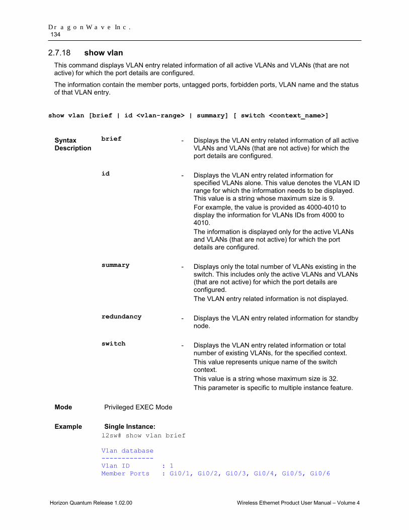
DragonWave Inc. 134
Horizon Quantum Release 1.02.00 Wireless Ethernet Product User Manual – Volume 4
show vlan 2.7.18This command displays VLAN entry related information of all active VLANs and VLANs (that are not active) for which the port details are configured.
The information contain the member ports, untagged ports, forbidden ports, VLAN name and the status of that VLAN entry.
show vlan [brief | id <vlan-range> | summary] [ switch <context_name>]
Syntax Description
brief - Displays the VLAN entry related information of all active VLANs and VLANs (that are not active) for which the port details are configured.
id - Displays the VLAN entry related information for specified VLANs alone. This value denotes the VLAN ID range for which the information needs to be displayed. This value is a string whose maximum size is 9. For example, the value is provided as 4000-4010 to display the information for VLANs IDs from 4000 to 4010. The information is displayed only for the active VLANs and VLANs (that are not active) for which the port details are configured.
summary - Displays only the total number of VLANs existing in the switch. This includes only the active VLANs and VLANs (that are not active) for which the port details are configured. The VLAN entry related information is not displayed.
redundancy - Displays the VLAN entry related information for standby node.
switch - Displays the VLAN entry related information or total number of existing VLANs, for the specified context. This value represents unique name of the switch context. This value is a string whose maximum size is 32. This parameter is specific to multiple instance feature.
Mode Privileged EXEC Mode
Example Single Instance: l2sw# show vlan brief Vlan database ------------- Vlan ID : 1 Member Ports : Gi0/1, Gi0/2, Gi0/3, Gi0/4, Gi0/5, Gi0/6
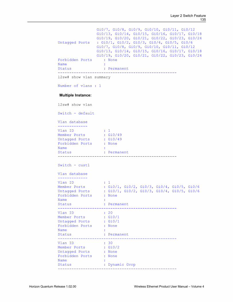
Layer 2 Switch Feature 135
Horizon Quantum Release 1.02.00 Wireless Ethernet Product User Manual – Volume 4
Gi0/7, Gi0/8, Gi0/9, Gi0/10, Gi0/11, Gi0/12 Gi0/13, Gi0/14, Gi0/15, Gi0/16, Gi0/17, Gi0/18 Gi0/19, Gi0/20, Gi0/21, Gi0/22, Gi0/23, Gi0/24 Untagged Ports : Gi0/1, Gi0/2, Gi0/3, Gi0/4, Gi0/5, Gi0/6 Gi0/7, Gi0/8, Gi0/9, Gi0/10, Gi0/11, Gi0/12 Gi0/13, Gi0/14, Gi0/15, Gi0/16, Gi0/17, Gi0/18 Gi0/19, Gi0/20, Gi0/21, Gi0/22, Gi0/23, Gi0/24 Forbidden Ports : None Name : Status : Permanent ---------------------------------------------------- l2sw# show vlan summary Number of vlans : 1 Multiple Instance: l2sw# show vlan Switch - default Vlan database ------------- Vlan ID : 1 Member Ports : Gi0/49 Untagged Ports : Gi0/49 Forbidden Ports : None Name : Status : Permanent ---------------------------------------------------- Switch - cust1 Vlan database ------------- Vlan ID : 1 Member Ports : Gi0/1, Gi0/2, Gi0/3, Gi0/4, Gi0/5, Gi0/6 Untagged Ports : Gi0/1, Gi0/2, Gi0/3, Gi0/4, Gi0/5, Gi0/6 Forbidden Ports : None Name : Status : Permanent ---------------------------------------------------- Vlan ID : 20 Member Ports : Gi0/1 Untagged Ports : Gi0/1 Forbidden Ports : None Name : Status : Permanent ---------------------------------------------------- Vlan ID : 30 Member Ports : Gi0/2 Untagged Ports : None Forbidden Ports : None Name : Status : Dynamic Gvrp ----------------------------------------------------

DragonWave Inc. 136
Horizon Quantum Release 1.02.00 Wireless Ethernet Product User Manual – Volume 4
• This command can be executed in the switch, only if the VLAN switching feature is started and enabled in the switch.
Related Commands
• no shutdown vlan - Starts and enables VLAN switching feature in the switch.
• vlan - Creates a VLAN in the l2sw and enters into the config-VLAN mode in which VLAN specific configurations are done.
• ports - Statically configures a VLAN entry with the required member ports, untagged ports and/or forbidden ports, and activates the VLAN.
• vlan active - Activates a VLAN in the switch.
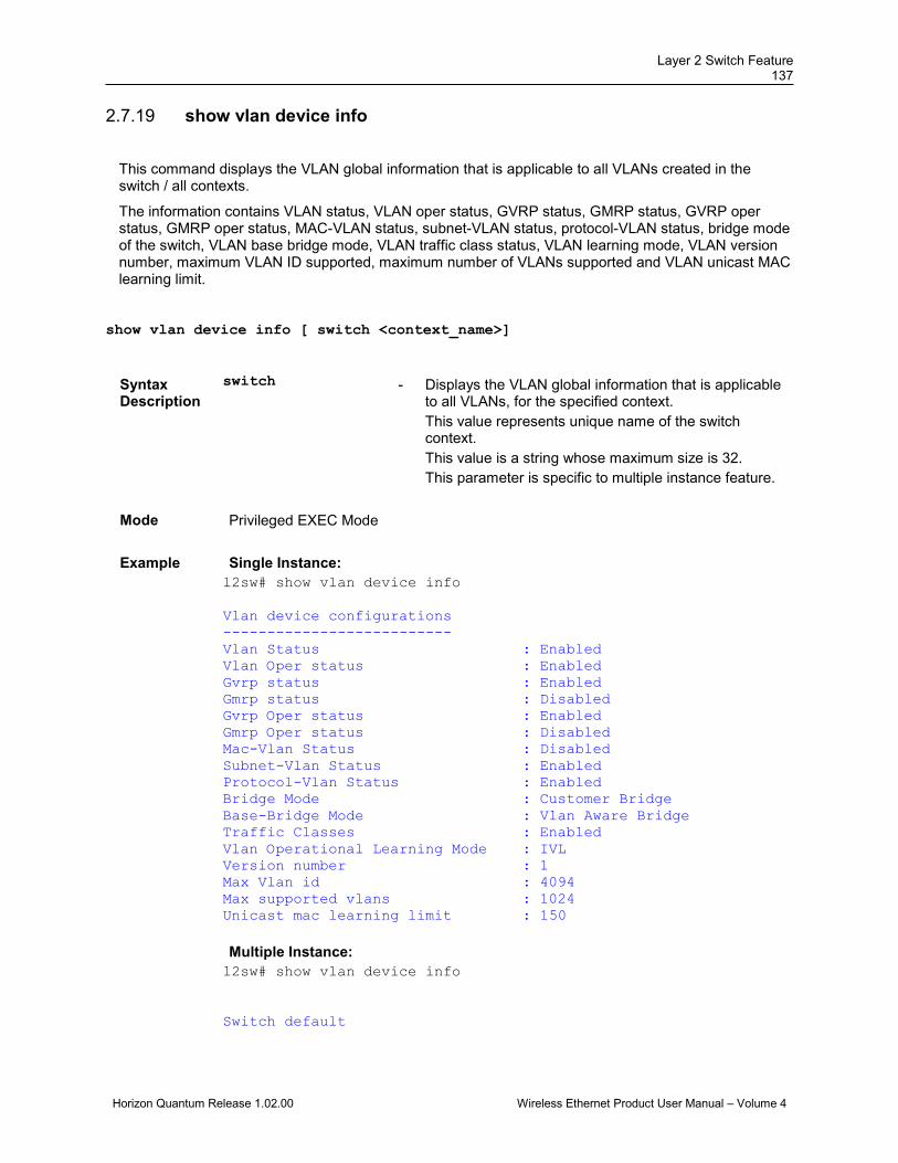
Layer 2 Switch Feature 137
Horizon Quantum Release 1.02.00 Wireless Ethernet Product User Manual – Volume 4
show vlan device info 2.7.19
This command displays the VLAN global information that is applicable to all VLANs created in the switch / all contexts.
The information contains VLAN status, VLAN oper status, GVRP status, GMRP status, GVRP oper status, GMRP oper status, MAC-VLAN status, subnet-VLAN status, protocol-VLAN status, bridge mode of the switch, VLAN base bridge mode, VLAN traffic class status, VLAN learning mode, VLAN version number, maximum VLAN ID supported, maximum number of VLANs supported and VLAN unicast MAC learning limit.
show vlan device info [ switch <context_name>]
Syntax Description
switch - Displays the VLAN global information that is applicable to all VLANs, for the specified context. This value represents unique name of the switch context. This value is a string whose maximum size is 32. This parameter is specific to multiple instance feature.
Mode Privileged EXEC Mode
Example Single Instance: l2sw# show vlan device info Vlan device configurations -------------------------- Vlan Status : Enabled Vlan Oper status : Enabled Gvrp status : Enabled Gmrp status : Disabled Gvrp Oper status : Enabled Gmrp Oper status : Disabled Mac-Vlan Status : Disabled Subnet-Vlan Status : Enabled Protocol-Vlan Status : Enabled Bridge Mode : Customer Bridge Base-Bridge Mode : Vlan Aware Bridge Traffic Classes : Enabled Vlan Operational Learning Mode : IVL Version number : 1 Max Vlan id : 4094 Max supported vlans : 1024 Unicast mac learning limit : 150 Multiple Instance: l2sw# show vlan device info Switch default
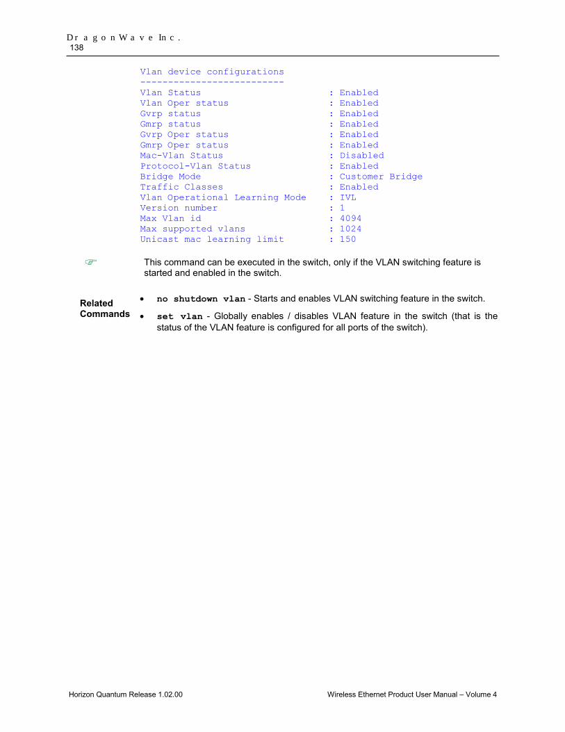
DragonWave Inc. 138
Horizon Quantum Release 1.02.00 Wireless Ethernet Product User Manual – Volume 4
Vlan device configurations -------------------------- Vlan Status : Enabled Vlan Oper status : Enabled Gvrp status : Enabled Gmrp status : Enabled Gvrp Oper status : Enabled Gmrp Oper status : Enabled Mac-Vlan Status : Disabled Protocol-Vlan Status : Enabled Bridge Mode : Customer Bridge Traffic Classes : Enabled Vlan Operational Learning Mode : IVL Version number : 1 Max Vlan id : 4094 Max supported vlans : 1024 Unicast mac learning limit : 150
This command can be executed in the switch, only if the VLAN switching feature is started and enabled in the switch.
Related Commands
• no shutdown vlan - Starts and enables VLAN switching feature in the switch.
• set vlan - Globally enables / disables VLAN feature in the switch (that is the status of the VLAN feature is configured for all ports of the switch).
Layer 2 Switch Feature 139
Horizon Quantum Release 1.02.00 Wireless Ethernet Product User Manual – Volume 4
show vlan port config 2.7.20
This command displays the VLAN related port specific information for all interfaces available in the switch / all contexts. The information contains PVID, acceptable frame type, port mode, filtering utility criteria, default priority value and status of ingress filtering feature, GVRP module, GMRP module, restricted VLAN registration feature, restricted group registration feature, MAC-based VLAN membership, subnet based VLAN membership, protocol-VLAN based membership and port protected feature.
show vlan port config [{port <interface-type> <interface-id> | switch <context_name>}]
Syntax Description
port - Displays the VLAN related port specific information for the specified interface. The details to be provided are: • <interface-type> - Sets the type of interface. The
interface can be:
1. fastethernet – Officially referred to as 100BASE-T standard. This is a version of LAN standard architecture that supports data transfer up to 100 Megabits per second.
2. gigabitethernet – A version of LAN standard architecture that supports data transfer up to 1 Gigabit per second.
3. extreme-ethernet – A version of Ethernet that supports data transfer up to 10 Gigabits per second. This Ethernet supports only full duplex links.
4. internal-lan – Internal LAN created on a bridge per IEEE 802.1ap.
5. port-channel – Logical interface that represents an aggregator which contains several ports aggregated together.
• <interface-id> - Sets the interface identifier. This is a unique value that represents the specific interface. This value is a combination of slot number and port number separated by a slash, for interface type other than internal-lan and port-channel. Only i-lan or port-channel ID is provided, for interface types internal-lan and port-channel.
switch - Displays the VLAN related port specific information, for
the specified context. This value represents unique name of the switch context. This value is a string whose maximum size is 32. This parameter is specific to multiple instance feature.
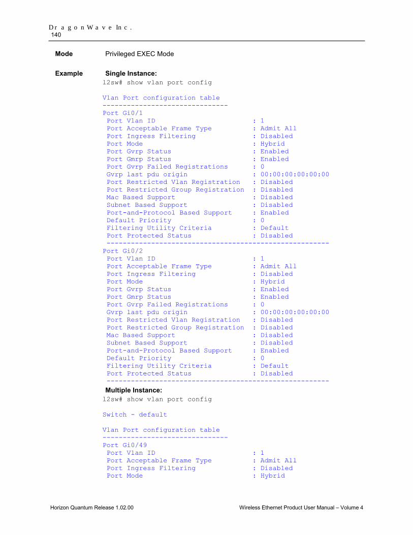
DragonWave Inc. 140
Horizon Quantum Release 1.02.00 Wireless Ethernet Product User Manual – Volume 4
Mode Privileged EXEC Mode
Example Single Instance: l2sw# show vlan port config Vlan Port configuration table ------------------------------- Port Gi0/1 Port Vlan ID : 1 Port Acceptable Frame Type : Admit All Port Ingress Filtering : Disabled Port Mode : Hybrid Port Gvrp Status : Enabled Port Gmrp Status : Enabled Port Gvrp Failed Registrations : 0 Gvrp last pdu origin : 00:00:00:00:00:00 Port Restricted Vlan Registration : Disabled Port Restricted Group Registration : Disabled Mac Based Support : Disabled Subnet Based Support : Disabled Port-and-Protocol Based Support : Enabled Default Priority : 0 Filtering Utility Criteria : Default Port Protected Status : Disabled ------------------------------------------------------- Port Gi0/2 Port Vlan ID : 1 Port Acceptable Frame Type : Admit All Port Ingress Filtering : Disabled Port Mode : Hybrid Port Gvrp Status : Enabled Port Gmrp Status : Enabled Port Gvrp Failed Registrations : 0 Gvrp last pdu origin : 00:00:00:00:00:00 Port Restricted Vlan Registration : Disabled Port Restricted Group Registration : Disabled Mac Based Support : Disabled Subnet Based Support : Disabled Port-and-Protocol Based Support : Enabled Default Priority : 0 Filtering Utility Criteria : Default Port Protected Status : Disabled ------------------------------------------------------- Multiple Instance: l2sw# show vlan port config Switch - default Vlan Port configuration table ------------------------------- Port Gi0/49 Port Vlan ID : 1 Port Acceptable Frame Type : Admit All Port Ingress Filtering : Disabled Port Mode : Hybrid

Layer 2 Switch Feature 141
Horizon Quantum Release 1.02.00 Wireless Ethernet Product User Manual – Volume 4
Port Gvrp Status : Enabled Port Gmrp Status : Enabled Port Gvrp Failed Registrations : 0 Gvrp last pdu origin : 00:00:00:00:00:00 Port Restricted Vlan Registration : Disabled Port Restricted Group Registration : Disabled Mac Based Support : Disabled Port-and-Protocol Based Support : Enabled Default Priority : 0 Dot1x Protocol Tunnel Status : Peer LACP Protocol Tunnel Status : Peer Spanning Tree Tunnel Status : Peer GVRP Protocol Tunnel Status : Peer GMRP Protocol Tunnel Status : Peer IGMP Protocol Tunnel Status : Peer Filtering Utility Criteria : Enhanced ------------------------------------------------------- Switch - cust1 Vlan Port configuration table ------------------------------- Port Gi0/1 Port Vlan ID : 20 Port Acceptable Frame Type : Admit All Port Ingress Filtering : Disabled Port Mode : Hybrid Port Gvrp Status : Enabled Port Gmrp Status : Enabled Port Gvrp Failed Registrations : 0 Gvrp last pdu origin : 00:00:00:00:00:00 Port Restricted Vlan Registration : Disabled Port Restricted Group Registration : Disabled Mac Based Support : Disabled Port-and-Protocol Based Support : Enabled Default Priority : 0 ------------------------------------------------------- Port Gi0/2 Port Vlan ID : 1 Port Acceptable Frame Type : Admit All Port Ingress Filtering : Disabled Port Mode : Hybrid Port Gvrp Status : Enabled Port Gmrp Status : Enabled Port Gvrp Failed Registrations : 0 Gvrp last pdu origin : 00:01:02:03:04:0e Port Restricted Vlan Registration : Disabled Port Restricted Group Registration : Disabled Mac Based Support : Disabled Port-and-Protocol Based Support : Enabled Default Priority : 0 -------------------------------------------------------
This command can be executed in the switch, only if the VLAN switching feature is started and enabled in the switch.

DragonWave Inc. 142
Horizon Quantum Release 1.02.00 Wireless Ethernet Product User Manual – Volume 4
Related Commands
• no shutdown vlan - Starts and enables VLAN switching feature in the switch.
• switchport pvid - Configures the PVID on the specified port.
• switchport mode - Configures the mode of operation for a switch port.
• switchport priority default - Configures the default ingress user priority for a port.

Layer 2 Switch Feature 143
Horizon Quantum Release 1.02.00 Wireless Ethernet Product User Manual – Volume 4
show vlan statistics 2.7.21
This command displays the unicast / broadcast statistics details of all active VLANs and VLANs (that are not active) for which the port details are configured.
The statistics details include VLAN ID, number of unicast packets received in the VLAN, number of multicast / broadcast packets received in the VLAN, number of unknown unicast packets flooded in the VLAN, number of known unicast packets forwarded in the VLAN, and number of known broadcast packets forwarded in the VLAN.
show vlan statistics [vlan <vlan-range>] [ switch <context_name>]
Syntax Description
vlan - Displays the unicast / broadcast statistics details for specified VLANs alone. This value denotes the VLAN ID range for which the details need to be displayed. This value is a string whose maximum size is 9. For example, the value is provided as 4000-4010 to display the details for VLAN IDs from 4000 to 4010. The details are displayed only for the VLANs that are activated and VLANs (that are not active) for which the port details are configured.
switch - Displays the unicast / broadcast statistics details of specified VLANs alone or of all active VLANs and VLANs (that are not active) for which the port details are configured, for the specified context. This value represents unique name of the switch context. This value is a string whose maximum size is 32. This parameter is specific to multiple instance feature.
Mode Privileged EXEC Mode
Example Single Instance l2sw# show vlan statistics vlan 1 Unicast/broadcast Vlan statistics ------------------------------------- Vlan Id : 1 Unicast frames received : 0 Mcast/Bcast frames received : 0 Unknown Unicast frames flooded : 0 Unicast frames transmitted : 0 Broadcast frames transmitted : 0 ------------------------------------- Multiple Instance l2sw# show vlan statistics vlan 1 switch sw1 Switch – sw1
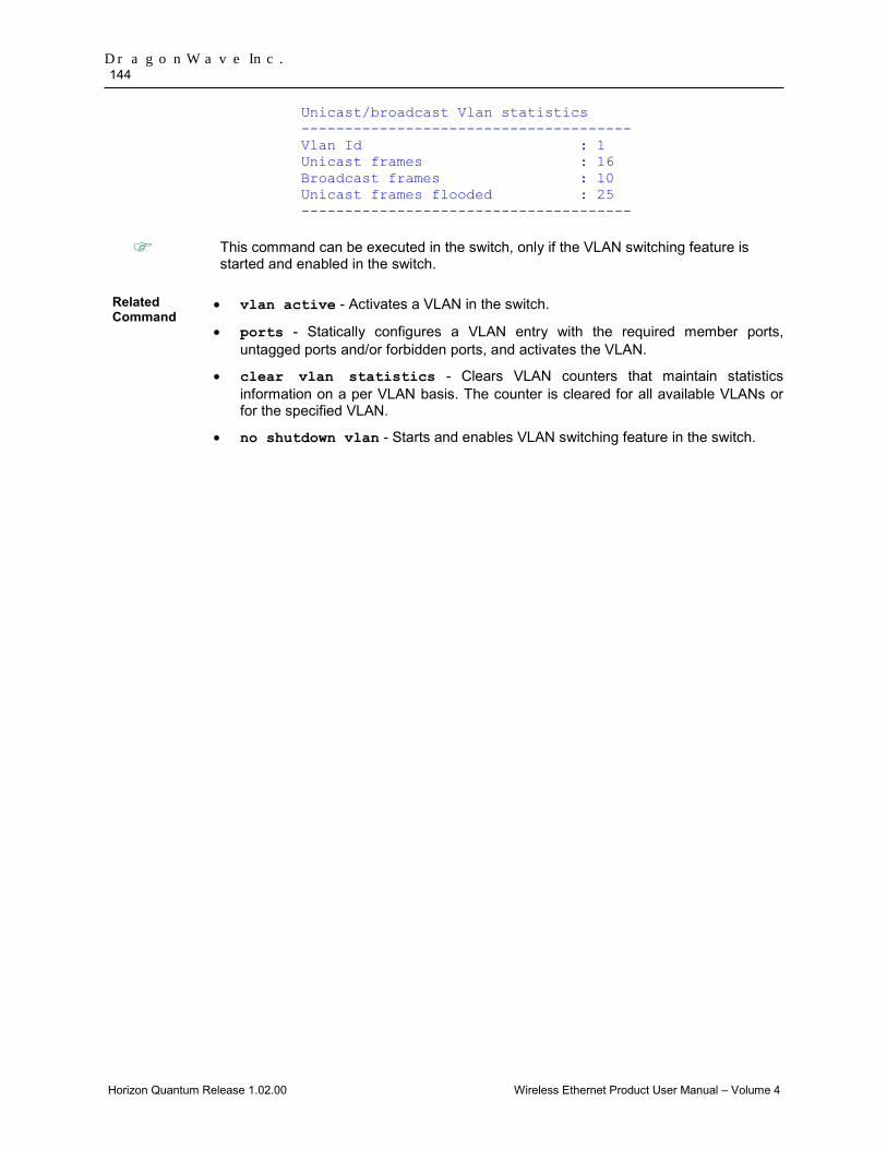
DragonWave Inc. 144
Horizon Quantum Release 1.02.00 Wireless Ethernet Product User Manual – Volume 4
Unicast/broadcast Vlan statistics -------------------------------------- Vlan Id : 1 Unicast frames : 16 Broadcast frames : 10 Unicast frames flooded : 25 --------------------------------------
This command can be executed in the switch, only if the VLAN switching feature is started and enabled in the switch.
Related Command
• vlan active - Activates a VLAN in the switch.
• ports - Statically configures a VLAN entry with the required member ports, untagged ports and/or forbidden ports, and activates the VLAN.
• clear vlan statistics - Clears VLAN counters that maintain statistics information on a per VLAN basis. The counter is cleared for all available VLANs or for the specified VLAN.
• no shutdown vlan - Starts and enables VLAN switching feature in the switch.
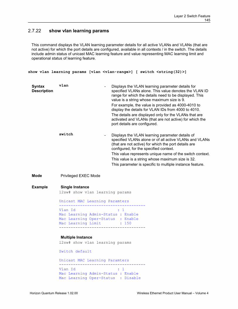
Layer 2 Switch Feature 145
Horizon Quantum Release 1.02.00 Wireless Ethernet Product User Manual – Volume 4
show vlan learning params 2.7.22
This command displays the VLAN learning parameter details for all active VLANs and VLANs (that are not active) for which the port details are configured, available in all contexts / in the switch. The details include admin status of unicast MAC learning feature and value representing MAC learning limit and operational status of learning feature.
show vlan learning params [vlan <vlan-range>] [ switch <string(32)>]
Syntax Description
vlan - Displays the VLAN learning parameter details for specified VLANs alone. This value denotes the VLAN ID range for which the details need to be displayed. This value is a string whose maximum size is 9. For example, the value is provided as 4000-4010 to display the details for VLAN IDs from 4000 to 4010. The details are displayed only for the VLANs that are activated and VLANs (that are not active) for which the port details are configured.
switch - Displays the VLAN learning parameter details of specified VLANs alone or of all active VLANs and VLANs (that are not active) for which the port details are configured, for the specified context. This value represents unique name of the switch context. This value is a string whose maximum size is 32. This parameter is specific to multiple instance feature.
Mode Privileged EXEC Mode
Example Single Instance l2sw# show vlan learning params Unicast MAC Learning Paramters ------------------------------------- Vlan Id : 1 Mac Learning Admin-Status : Enable Mac Learning Oper-Status : Enable Mac Learning Limit : 150 ------------------------------------- Multiple Instance l2sw# show vlan learning params Switch default Unicast MAC Learning Paramters ------------------------------------- Vlan Id : 1 Mac Learning Admin-Status : Enable Mac Learning Oper-Status : Disable
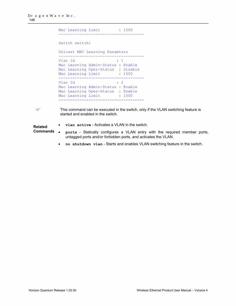
DragonWave Inc. 146
Horizon Quantum Release 1.02.00 Wireless Ethernet Product User Manual – Volume 4
Mac Learning Limit : 1500 ------------------------------------- Switch switch1 Unicast MAC Learning Paramters ------------------------------------- Vlan Id : 1 Mac Learning Admin-Status : Enable Mac Learning Oper-Status : Disable Mac Learning Limit : 1500 ------------------------------------- Vlan Id : 2 Mac Learning Admin-Status : Enable Mac Learning Oper-Status : Enable Mac Learning Limit : 1500 -------------------------------------
This command can be executed in the switch, only if the VLAN switching feature is started and enabled in the switch.
Related Commands
• vlan active - Activates a VLAN in the switch.
• ports - Statically configures a VLAN entry with the required member ports, untagged ports and/or forbidden ports, and activates the VLAN.
• no shutdown vlan - Starts and enables VLAN switching feature in the switch.

Layer 2 Switch Feature 147
Horizon Quantum Release 1.02.00 Wireless Ethernet Product User Manual – Volume 4
show mac-address-table 2.7.23
This command displays all static / dynamic unicast and multicast MAC entries created in the MAC address table. These entries contain VLAN ID, unicast / multicast MAC address, unicast backbone MAC address of peer backbone edge bridge, member ports, the type of entry (that is static, learnt and so on), and total number of entries displayed.
show mac-address-table [vlan <vlan-range>] [address <aa:aa:aa:aa:aa:aa>] [{interface <interface-type> <interface-id> | switch <context_name>}]
Syntax Description
vlan - Displays all static / dynamic unicast and multicast MAC entries created in the MAC address table for the specified VLANs alone. This value denotes the VLAN ID range for which the entries need to be displayed. This value is a string whose maximum size is 9. For example, the value is provided as 4000-4010 to display the entries for VLAN IDs from 4000 to 4010.
address - Displays all static / dynamic unicast and multicast MAC entries created in the MAC address table for the specified unicast / multicast MAC address.
interface - Displays all static / dynamic unicast and multicast MAC entries for the specified interface. The details to be provided are: • <interface-type> - Sets the type of interface. The
interface can be:
1. fastethernet – Officially referred to as 100BASE-T standard. This is a version of LAN standard architecture that supports data transfer up to 100 Megabits per second.
2. gigabitethernet – A version of LAN standard architecture that supports data transfer up to 1 Gigabit per second.
3. extreme-ethernet – A version of Ethernet that supports data transfer up to 10 Gigabits per second. This Ethernet supports only full duplex links.
4. internal-lan – Internal LAN created on a bridge per IEEE 802.1ap.
5. port-channel – Logical interface that represents an aggregator which contains several ports aggregated together.
• <interface-id> - Sets the interface identifier. This is a unique value that represents the specific interface. This value is a combination of slot number and port number separated by a slash,
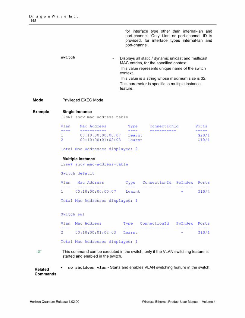
DragonWave Inc. 148
Horizon Quantum Release 1.02.00 Wireless Ethernet Product User Manual – Volume 4
for interface type other than internal-lan and port-channel. Only i-lan or port-channel ID is provided, for interface types internal-lan and port-channel.
switch - Displays all static / dynamic unicast and multicast
MAC entries, for the specified context. This value represents unique name of the switch context. This value is a string whose maximum size is 32. This parameter is specific to multiple instance feature.
Mode Privileged EXEC Mode
Example Single Instance l2sw# show mac-address-table Vlan Mac Address Type ConnectionId Ports ---- ----------- ---- ----------- ----- 1 00:10:00:00:00:07 Learnt Gi0/1 2 00:10:00:01:02:03 Learnt Gi0/1 Total Mac Addresses displayed: 2 Multiple Instance l2sw# show mac-address-table Switch default Vlan Mac Address Type ConnectionId PwIndex Ports ---- ----------- ---- ------------ ------- ----- 1 00:10:00:00:00:07 Learnt - Gi0/4 Total Mac Addresses displayed: 1 Switch sw1 Vlan Mac Address Type ConnectionId PwIndex Ports ---- ----------- ---- ------------ ------- ----- 2 00:10:00:01:02:03 Learnt - Gi0/1 Total Mac Addresses displayed: 1
This command can be executed in the switch, only if the VLAN switching feature is started and enabled in the switch.
Related Commands
• no shutdown vlan - Starts and enables VLAN switching feature in the switch.

Layer 2 Switch Feature 149
Horizon Quantum Release 1.02.00 Wireless Ethernet Product User Manual – Volume 4
show mac-address-table count 2.7.24
This command displays the total number of static / dynamic unicast and multicast MAC address entries created in the FDB table. The count is displayed for all active VLANs, VLANs (that are not active) for which the port details are configured, and VLANs for which the MAC address table entries are created.
show mac-address-table count [vlan <vlan-id(1-4094)>] [ switch <context_name>]
Syntax Description
vlan - Displays the total number of static / dynamic unicast and multicast MAC address entries available in the FDB table for the specified VLAN ID. This is a unique value that represents the specific VLAN. This value ranges between 1 and 4094.
switch - Displays the total number of static / dynamic unicast and multicast MAC address entries, for the specified context. This value represents unique name of the switch context. This value is a string whose maximum size is 32. This parameter is specific to multiple instance feature.
Mode Privileged EXEC Mode
Example Single Instance l2sw# show mac-address-table count Mac Entries for Vlan 1: -------------------------- Dynamic Unicast Address Count : 1 Dynamic Multicast Address Count : 0 Static Unicast Address Count : 1 Static Multicast Address Count : 1 ---------------------------------------- Mac Entries for Vlan 2: -------------------------- Dynamic Unicast Address Count : 1 Dynamic Multicast Address Count : 0 Static Unicast Address Count : 1 Static Multicast Address Count : 0 ---------------------------------------- Multiple Instance: l2sw# show mac-address-table count switch cust1
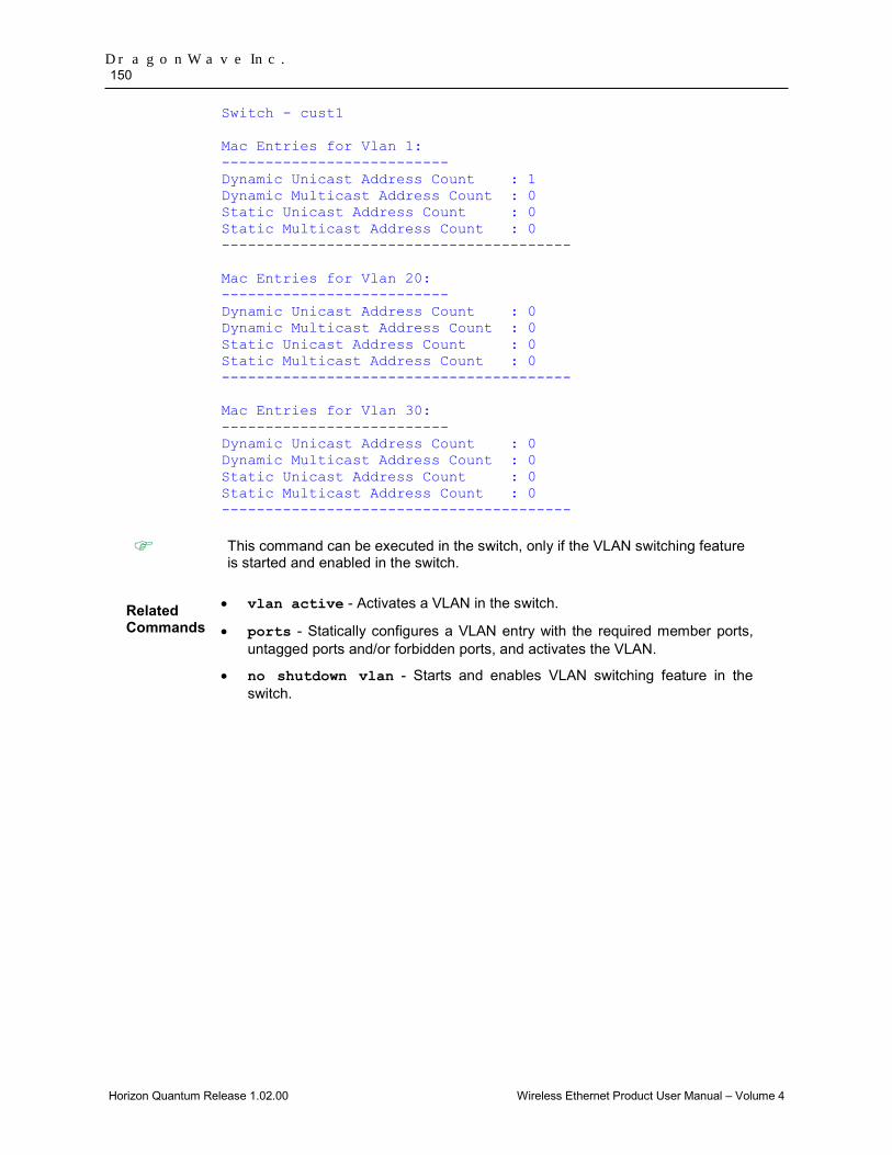
DragonWave Inc. 150
Horizon Quantum Release 1.02.00 Wireless Ethernet Product User Manual – Volume 4
Switch - cust1 Mac Entries for Vlan 1: -------------------------- Dynamic Unicast Address Count : 1 Dynamic Multicast Address Count : 0 Static Unicast Address Count : 0 Static Multicast Address Count : 0 ---------------------------------------- Mac Entries for Vlan 20: -------------------------- Dynamic Unicast Address Count : 0 Dynamic Multicast Address Count : 0 Static Unicast Address Count : 0 Static Multicast Address Count : 0 ---------------------------------------- Mac Entries for Vlan 30: -------------------------- Dynamic Unicast Address Count : 0 Dynamic Multicast Address Count : 0 Static Unicast Address Count : 0 Static Multicast Address Count : 0 ----------------------------------------
This command can be executed in the switch, only if the VLAN switching feature is started and enabled in the switch.
Related Commands
• vlan active - Activates a VLAN in the switch.
• ports - Statically configures a VLAN entry with the required member ports, untagged ports and/or forbidden ports, and activates the VLAN.
• no shutdown vlan - Starts and enables VLAN switching feature in the switch.
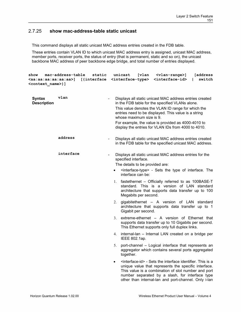
Layer 2 Switch Feature 151
Horizon Quantum Release 1.02.00 Wireless Ethernet Product User Manual – Volume 4
show mac-address-table static unicast 2.7.25
This command displays all static unicast MAC address entries created in the FDB table.
These entries contain VLAN ID to which unicast MAC address entry is assigned, unicast MAC address, member ports, receiver ports, the status of entry (that is permanent, static and so on), the unicast backbone MAC address of peer backbone edge bridge, and total number of entries displayed.
show mac-address-table static unicast [vlan <vlan-range>] [address <aa:aa:aa:aa:aa:aa>] [{interface <interface-type> <interface-id> | switch <context_name>}]
Syntax Description
vlan - Displays all static unicast MAC address entries created in the FDB table for the specified VLANs alone. This value denotes the VLAN ID range for which the entries need to be displayed. This value is a string whose maximum size is 9. For example, the value is provided as 4000-4010 to display the entries for VLAN IDs from 4000 to 4010.
address - Displays all static unicast MAC address entries created in the FDB table for the specified unicast MAC address.
interface - Displays all static unicast MAC address entries for the specified interface. The details to be provided are: • <interface-type> - Sets the type of interface. The
interface can be:
1. fastethernet – Officially referred to as 100BASE-T standard. This is a version of LAN standard architecture that supports data transfer up to 100 Megabits per second.
2. gigabitethernet – A version of LAN standard architecture that supports data transfer up to 1 Gigabit per second.
3. extreme-ethernet – A version of Ethernet that supports data transfer up to 10 Gigabits per second. This Ethernet supports only full duplex links.
4. internal-lan – Internal LAN created on a bridge per IEEE 802.1ap.
5. port-channel – Logical interface that represents an aggregator which contains several ports aggregated together.
• <interface-id> - Sets the interface identifier. This is a unique value that represents the specific interface. This value is a combination of slot number and port number separated by a slash, for interface type other than internal-lan and port-channel. Only i-lan

DragonWave Inc. 152
Horizon Quantum Release 1.02.00 Wireless Ethernet Product User Manual – Volume 4
or port-channel ID is provided, for interface types internal-lan and port-channel.
switch - Displays all static unicast MAC entries, for the specified
context. This value represents unique name of the switch context. This value is a string whose maximum size is 32. This parameter is specific to multiple instance feature.
Mode Privileged EXEC Mode
Example Single Instance: l2sw# show mac-address-table static unicast Vlan Mac Address RecvPort Status ConnectionId Ports ---- ----------- -------- ------ ----- ------- 2 00:11:22:33:44:55 Gi0/2 Del-OnTimeout Gi0/3 Total Mac Addresses displayed: 1 Multiple Instance: l2sw# sh mac-address-table static unicast switch cust1 Switch - cust1 Vlan Mac Address SrvInst/ Status Ports ---- ----------- -------- ------ ----- 1 00:11:22:33:44:55 Gi0/2 Permanent Gi0/3 Total Mac Addresses displayed: 1
This command can be executed in the switch, only if the VLAN switching feature is started and enabled in the switch.
Related Commands
• no shutdown vlan - Starts and enables VLAN switching feature in the switch.

Layer 2 Switch Feature 153
Horizon Quantum Release 1.02.00 Wireless Ethernet Product User Manual – Volume 4
show mac-address-table static multicast 2.7.26This command displays the static multicast MAC address entries created in the FDB table.
These entries contain VLAN ID to which multicast MAC address entry is assigned, multicast MAC address, member ports, receiver ports, forbidden ports, the status of entry (that is permanent, static and so on), and total number of entries displayed.
show mac-address-table static multicast [vlan <vlan-range>] [address <aa:aa:aa:aa:aa:aa>] [{interface <interface-type> <interface-id> | switch <context_name>}]
Syntax Description
vlan - Displays all static multicast MAC address entries created in the FDB table for the specified VLANs alone. This value denotes the VLAN ID range for which the entries need to be displayed. This value is a string whose maximum size is 9. For example, the value is provided as 4000-4010 to display the entries for VLAN IDs from 4000 to 4010.
address - Displays all static multicast MAC address entries created in the FDB table for the specified unicast MAC address.
interface - Displays all static multicast MAC address entries for the specified interface. The details to be provided are: • <interface-type> - Sets the type of interface.
The interface can be:
1. fastethernet – Officially referred to as 100BASE-T standard. This is a version of LAN standard architecture that supports data transfer up to 100 Megabits per second.
2. gigabitethernet – A version of LAN standard architecture that supports data transfer up to 1 Gigabit per second.
3. extreme-ethernet – A version of Ethernet that supports data transfer up to 10 Gigabits per second. This Ethernet supports only full duplex links.
4. internal-lan – Internal LAN created on a bridge per IEEE 802.1ap.
5. port-channel – Logical interface that represents an aggregator which contains several ports aggregated together.
• <interface-id> - Sets the interface identifier. This is a unique value that represents the specific interface. This value is a combination of slot number and port number separated by a
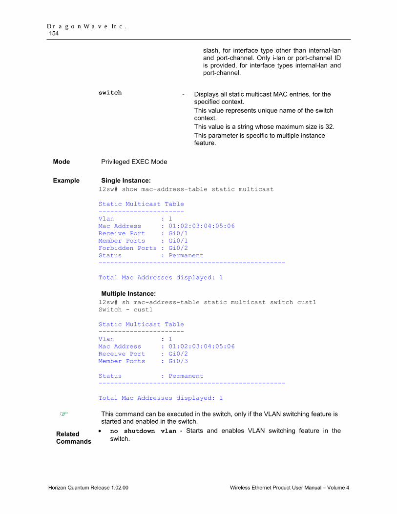
DragonWave Inc. 154
Horizon Quantum Release 1.02.00 Wireless Ethernet Product User Manual – Volume 4
slash, for interface type other than internal-lan and port-channel. Only i-lan or port-channel ID is provided, for interface types internal-lan and port-channel.
switch - Displays all static multicast MAC entries, for the
specified context. This value represents unique name of the switch context. This value is a string whose maximum size is 32. This parameter is specific to multiple instance feature.
Mode Privileged EXEC Mode
Example Single Instance: l2sw# show mac-address-table static multicast Static Multicast Table ---------------------- Vlan : 1 Mac Address : 01:02:03:04:05:06 Receive Port : Gi0/1 Member Ports : Gi0/1 Forbidden Ports : Gi0/2 Status : Permanent ------------------------------------------------ Total Mac Addresses displayed: 1 Multiple Instance: l2sw# sh mac-address-table static multicast switch cust1 Switch - cust1 Static Multicast Table ---------------------- Vlan : 1 Mac Address : 01:02:03:04:05:06 Receive Port : Gi0/2 Member Ports : Gi0/3 Status : Permanent ------------------------------------------------ Total Mac Addresses displayed: 1
This command can be executed in the switch, only if the VLAN switching feature is started and enabled in the switch.
Related Commands
• no shutdown vlan - Starts and enables VLAN switching feature in the switch.

Layer 2 Switch Feature 155
Horizon Quantum Release 1.02.00 Wireless Ethernet Product User Manual – Volume 4
show mac-address-table dynamic unicast 2.7.27
This command displays all dynamically learnt unicast entries from the MAC address table.
These entries contain VLAN ID for which unicast MAC address entry is learnt, unicast MAC address, ports through which the entry is learnt, the status of entry (that is permanent, static and so on), the unicast backbone MAC address of peer backbone edge bridge, and total number of entries displayed.
show mac-address-table dynamic unicast [vlan <vlan-range>] [address <aa:aa:aa:aa:aa:aa>] [{interface <interface-type> <interface-id> | switch <context_name>}]
Syntax Description
vlan - Displays all dynamically learnt unicast entries from the MAC address table for the specified VLANs alone. This value denotes the VLAN ID range for which the entries need to be displayed. This value is a string whose maximum size is 9. For example, the value is provided as 4000-4010 to display the entries for VLAN IDs from 4000 to 4010.
address - Displays all dynamically learnt unicast entries from the MAC address table for the specified unicast MAC address.
interface - Displays all dynamically learnt unicast entries from the MAC address table for the specified interface. The details to be provided are: • <interface-type> - Sets the type of interface. The
interface can be:
1. fastethernet – Officially referred to as 100BASE-T standard. This is a version of LAN standard architecture that supports data transfer up to 100 Megabits per second.
2. gigabitethernet – A version of LAN standard architecture that supports data transfer up to 1 Gigabit per second.
3. extreme-ethernet – A version of Ethernet that supports data transfer up to 10 Gigabits per second. This Ethernet supports only full duplex links.
4. internal-lan – Internal LAN created on a bridge per IEEE 802.1ap.
5. port-channel – Logical interface that represents an aggregator which contains several ports aggregated together.
• <interface-id> - Sets the interface identifier. This is a unique value that represents the specific

DragonWave Inc. 156
Horizon Quantum Release 1.02.00 Wireless Ethernet Product User Manual – Volume 4
interface. This value is a combination of slot number and port number separated by a slash, for interface type other than internal-lan and port-channel. Only i-lan or port-channel ID is provided, for interface types internal-lan and port-channel.
switch - Displays all dynamically learnt unicast entries, for the
specified context. This value represents unique name of the switch context. This value is a string whose maximum size is 32. This parameter is specific to multiple instance feature.
Mode Privileged EXEC Mode
Example Single Instance: l2sw# show mac-address-table dynamic unicast vlan 2 Vlan Mac Address Type ConnectionId Ports ---- ----------- ---- ------------ ----- 2 00:01:02:03:04:21 Learnt Gi0/1 Total Mac Addresses displayed: 1 Multiple Instance: l2sw# show mac-address-table dynamic unicast Switch - default Vlan Mac Address Type Ports ---- ----------- ---- ----- 1 00:02:02:03:04:04 Learnt Gi0/2 1 00:03:02:03:04:04 Learnt Gi0/3 2 00:02:02:03:04:04 Learnt Gi0/2 2 00:03:02:03:04:04 Learnt Gi0/3 3 00:02:02:03:04:04 Learnt Gi0/2 3 00:03:02:03:04:04 Learnt Gi0/3 Total Mac Addresses displayed: 6
This command can be executed in the switch, only if the VLAN switching feature is started and enabled in the switch.
Related Commands
• no shutdown vlan - Starts and enables VLAN switching feature in the switch.

Layer 2 Switch Feature 157
Horizon Quantum Release 1.02.00 Wireless Ethernet Product User Manual – Volume 4
show mac-address-table dynamic multicast 2.7.28
This command displays all dynamically learnt multicast entries from the MAC address table.
These entries contain VLAN ID for which multicast MAC address entry is learnt, multicast MAC address, ports through which the entry is learnt, the status of entry (that is permanent, static and so on), the unicast backbone MAC address of peer backbone edge bridge, and total number of entries displayed.
show mac-address-table dynamic multicast [vlan <vlan-range>] [address <aa:aa:aa:aa:aa:aa>] [{interface <interface-type> <interface-id> | switch <context_name>}]
Syntax Description
vlan - Displays all dynamically learnt multicast entries from the MAC address table for the specified VLANs alone. This value denotes the VLAN ID range for which the entries need to be displayed. This value is a string whose maximum size is 9. For example, the value is provided as 4000-4010 to display the entries for VLAN IDs from 4000 to 4010.
address - Displays all dynamically learnt multicast entries from the MAC address table for the specified unicast MAC address.
interface - Displays all dynamically learnt multicast entries from the MAC address table for the specified interface. The details to be provided are: • <interface-type> - Sets the type of interface.
The interface can be:
1. fastethernet – Officially referred to as 100BASE-T standard. This is a version of LAN standard architecture that supports data transfer up to 100 Megabits per second.
2. gigabitethernet – A version of LAN standard architecture that supports data transfer up to 1 Gigabit per second.
3. extreme-ethernet – A version of Ethernet that supports data transfer up to 10 Gigabits per second. This Ethernet supports only full duplex links.
4. internal-lan – Internal LAN created on a bridge per IEEE 802.1ap.
5. port-channel – Logical interface that
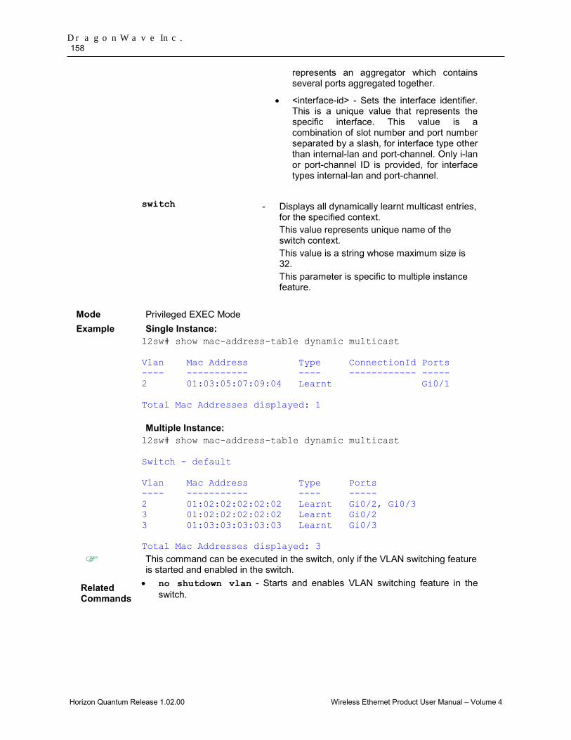
DragonWave Inc. 158
Horizon Quantum Release 1.02.00 Wireless Ethernet Product User Manual – Volume 4
represents an aggregator which contains several ports aggregated together.
• <interface-id> - Sets the interface identifier. This is a unique value that represents the specific interface. This value is a combination of slot number and port number separated by a slash, for interface type other than internal-lan and port-channel. Only i-lan or port-channel ID is provided, for interface types internal-lan and port-channel.
switch - Displays all dynamically learnt multicast entries,
for the specified context. This value represents unique name of the switch context. This value is a string whose maximum size is 32. This parameter is specific to multiple instance feature.
Mode Privileged EXEC Mode Example Single Instance:
l2sw# show mac-address-table dynamic multicast Vlan Mac Address Type ConnectionId Ports ---- ----------- ---- ------------ ----- 2 01:03:05:07:09:04 Learnt Gi0/1 Total Mac Addresses displayed: 1 Multiple Instance: l2sw# show mac-address-table dynamic multicast Switch - default Vlan Mac Address Type Ports ---- ----------- ---- ----- 2 01:02:02:02:02:02 Learnt Gi0/2, Gi0/3 3 01:02:02:02:02:02 Learnt Gi0/2 3 01:03:03:03:03:03 Learnt Gi0/3 Total Mac Addresses displayed: 3
This command can be executed in the switch, only if the VLAN switching feature is started and enabled in the switch.
Related Commands
• no shutdown vlan - Starts and enables VLAN switching feature in the switch.
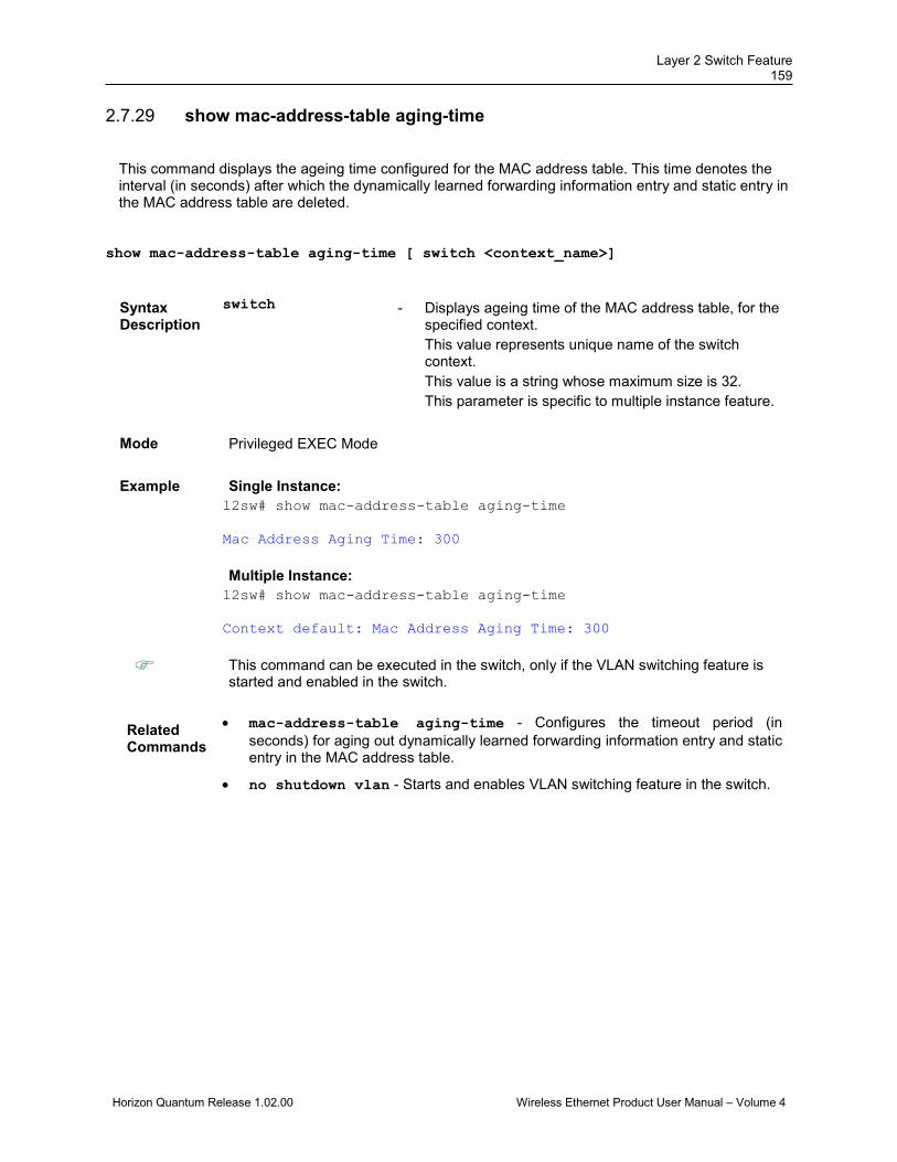
Layer 2 Switch Feature 159
Horizon Quantum Release 1.02.00 Wireless Ethernet Product User Manual – Volume 4
show mac-address-table aging-time 2.7.29
This command displays the ageing time configured for the MAC address table. This time denotes the interval (in seconds) after which the dynamically learned forwarding information entry and static entry in the MAC address table are deleted.
show mac-address-table aging-time [ switch <context_name>]
Syntax Description
switch - Displays ageing time of the MAC address table, for the specified context. This value represents unique name of the switch context. This value is a string whose maximum size is 32. This parameter is specific to multiple instance feature.
Mode Privileged EXEC Mode
Example Single Instance: l2sw# show mac-address-table aging-time Mac Address Aging Time: 300 Multiple Instance: l2sw# show mac-address-table aging-time Context default: Mac Address Aging Time: 300
This command can be executed in the switch, only if the VLAN switching feature is started and enabled in the switch.
Related Commands
• mac-address-table aging-time - Configures the timeout period (in seconds) for aging out dynamically learned forwarding information entry and static entry in the MAC address table.
• no shutdown vlan - Starts and enables VLAN switching feature in the switch.
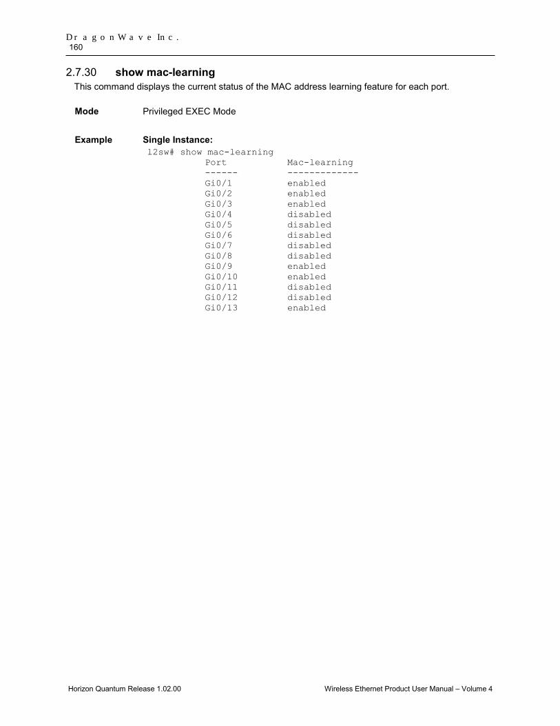
DragonWave Inc. 160
Horizon Quantum Release 1.02.00 Wireless Ethernet Product User Manual – Volume 4
show mac-learning 2.7.30This command displays the current status of the MAC address learning feature for each port. Mode
Privileged EXEC Mode
Example Single Instance:
l2sw# show mac-learning Port Mac-learning ------ ------------- Gi0/1 enabled Gi0/2 enabled Gi0/3 enabled Gi0/4 disabled Gi0/5 disabled Gi0/6 disabled Gi0/7 disabled Gi0/8 disabled Gi0/9 enabled Gi0/10 enabled Gi0/11 disabled Gi0/12 disabled Gi0/13 enabled

Horizon Quantum Release 1.02.00 Wireless Ethernet Product User Manual – Volume 4
3.0 Ethernet Connectivity Fault Management (ECFM) IEEE 802.1ag and ITU-T Y.1731 standards define mechanisms that provide Ethernet Connectivity Fault Management (ECFM). The fault management mechanisms defined by Y.1731 are basically the same as those for 802.1ag, but with subtle differences in the concept of the management domain and its association. ITU-T Y.1731 also defines performance monitoring mechanisms.
ECFM comprises a number of fault management mechanisms that work together to help administrators debug Ethernet networks. These are:
• connectivity check message (CCM) • link trace message (LTM) • loopback message (LBM) • remote defect indication (RDI) • alarm indication signal (AIS – supported by Y.1731 only)
The Y.1731 performance monitoring mechanisms include: • frame loss measurement (LM) • frame delay measurement (DM) • throughput measurement
The Horizon Quantum supports the CCM, LTM, LBM, and RDI mechanisms of 802.1ag and Y.1731 mechanisms noted above. The AIS and performance monitoring mechanisms of Y.1731 are not supported. However Horizon Quantum will respond to DM messages.
ECFM is supported on all ports of the Horizon Quantum. The wireless side port is also considered as one of the ports and it is indexed as port 9 for ECFM.
Entering networking details of maintenance domains (MD), maintenance associations (MA), maintenance association intermediate points (MIP) and maintenance end points (MEP), into a database on various devices in an Ethernet network, allows operators to trace fault conditions throughout that network.
The Horizon Quantum is limited in the number of the above elements it can manage as follows:
• MD – 32 • MA – 32 per MD • MEP – 1024
NOTE: Only 32 MEPs are supported to work with 100ms CCM period. Any configurations beyond these limits are not blocked by the system, but they are not supported.
There are four steps to configuring ECFM. Each step comprises the issuing of a number of CLI “set” commands. Some of these commands must be entered in a specific order for the configuration to be successful.
Section 3.1 shows the basic steps involved in configuring ECFM on the Horizon Quantum.
Section 3.2 has configuration examples that show, in more detail, how to configure the Horizon Quantum for ECFM.
Section 3.3 contains all the CLI commands associated with ECFM, with a brief explanation of their function.
Note that ECFM uses a special MAC address that the network system discovers through connectivity check messages sent out by the CE’s. This allows Loopback and Linktrace activities to be performed. Since the ECFM MAC address is auto discovered by the network system, there is no need to configure this address in the Horizon Quantum. However, if you wish to determine what the Horizon Quantum ECFM MAC address is, use the CLI command get ecfm maintenance-point local.
Note that the ECFM flow mapping feature (see Section Error! Reference source not found.) is overridden when ECFM is enabled on the node.

DragonWave Inc. 162
Horizon Quantum Release 1.02.00 Wireless Ethernet Product User Manual – Volume 4
3.1 Steps to Configuring ECFM There are four steps to configuring ecfm. Each step comprises the issuing of a number of CLI “set” commands. Some of these commands must be entered in a specific order for the configuration to be successful. The following table shows the steps and also indicates which commands within those steps relate to 802.1 ag and Y.1731.
Configuring ECFM – Step 1 ECFM Commands 802.1ag Y.1731 ECFM Global Setting set ecfm on ✓ ✓
set ecfm y1731 on ✓
set ecfm port 1 on ✓ ✓
set ecfm oui aa:bb:cc ✓ ✓
set ecfm error-log on ✓
set ecfm start ✓ ✓
set ecfm mep crosscheck start-delay ✓ ✓
set ecfm traceroute cache on ✓ ✓
set ecfm traceroute cachesize ✓ ✓
set ecfm traceroute cache holdtime ✓ ✓
set ecfm mip ccm-database caching ✓ ✓
set ecfm mip ccm-database size ✓ ✓
set ecfm mip ccm-database holdtime ✓ ✓
set ecfm associate vlan-id ✓ ✓
Configuring ECFM – Step 2 ECFM Commands 802.1ag Y.1731 Define Domain, Service, and MEPs Note: The sequence, below, must be followed in this step: 1. Domain 2. Domain feature (archive-hold-time,
mip-creation-criteria) 3. Service within the domain
set ecfm default-domain vlan/global ✓ ✓
set ecfm domain DOMAIN-ONE ✓ ✓
set ecfm mip-creation-criteria ✓ ✓
set ecfm mep archieve-hold-time ✓ ✓
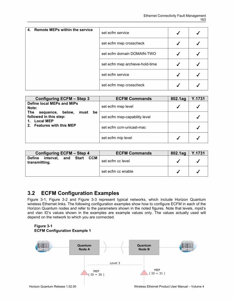
Ethernet Connectivity Fault Management 163
Horizon Quantum Release 1.02.00 Wireless Ethernet Product User Manual – Volume 4
QuantumNode A
QuantumNode B
Level 3
MEP( ID = 30 )
MEP( ID = 31 )
4. Remote MEPs within the service
set ecfm service ✓ ✓
set ecfm mep crosscheck ✓ ✓
set ecfm domain DOMAIN-TWO ✓ ✓
set ecfm mep archieve-hold-time ✓ ✓
set ecfm service ✓ ✓
set ecfm mep crosscheck ✓ ✓
3.2 ECFM Configuration Examples Figure 3-1, Figure 3-2 and Figure 3-3 represent typical networks, which include Horizon Quantum wireless Ethernet links. The following configuration examples show how to configure ECFM in each of the Horizon Quantum nodes and refer to the parameters shown in the noted figures. Note that levels, mpid’s and vlan ID’s values shown in the examples are example values only. The values actually used will depend on the network to which you are connected.
Figure 3-1 ECFM Configuration Example 1
Configuring ECFM – Step 3 ECFM Commands 802.1ag Y.1731 Define local MEPs and MIPs Note: The sequence, below, must be followed in this step: 1. Local MEP 2. Features with this MEP
set ecfm mep level ✓ ✓
set ecfm mep-capability level ✓
set ecfm ccm-unicast-mac ✓
set ecfm mip level ✓ ✓
Configuring ECFM – Step 4 ECFM Commands 802.1ag Y.1731 Define interval, and Start CCM transmitting.
set ecfm cc level ✓ ✓
set ecfm cc enable ✓ ✓
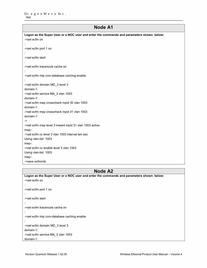
DragonWave Inc. 164
Horizon Quantum Release 1.02.00 Wireless Ethernet Product User Manual – Volume 4
Node A1 Logon as the Super User or a NOC user and enter the commands and parameters shown below: ->set ecfm on : ->set ecfm port 1 on : ->set ecfm start : ->set ecfm traceroute cache on : ->set ecfm mip ccm-database caching enable : ->set ecfm domain MD_3 level 3 domain-1: ->set ecfm service MA_3 vlan 1003 domain-1: ->set ecfm mep crosscheck mpid 30 vlan 1003 domain-1: ->set ecfm mep crosscheck mpid 31 vlan 1003 domain-1: -> ->set ecfm mep level 3 inward mpid 31 vlan 1003 active mep-: ->set ecfm cc level 3 vlan 1003 interval ten-sec Using vlan-list: 1003. mep-: ->set ecfm cc enable level 3 vlan 1003 Using vlan-list: 1003. mep-: ->save ecfmmib
Node A2 Logon as the Super User or a NOC user and enter the commands and parameters shown below: ->set ecfm on : ->set ecfm port 1 on : ->set ecfm start : ->set ecfm traceroute cache on : ->set ecfm mip ccm-database caching enable : ->set ecfm domain MD_3 level 3 domain-1: ->set ecfm service MA_3 vlan 1003 domain-1:
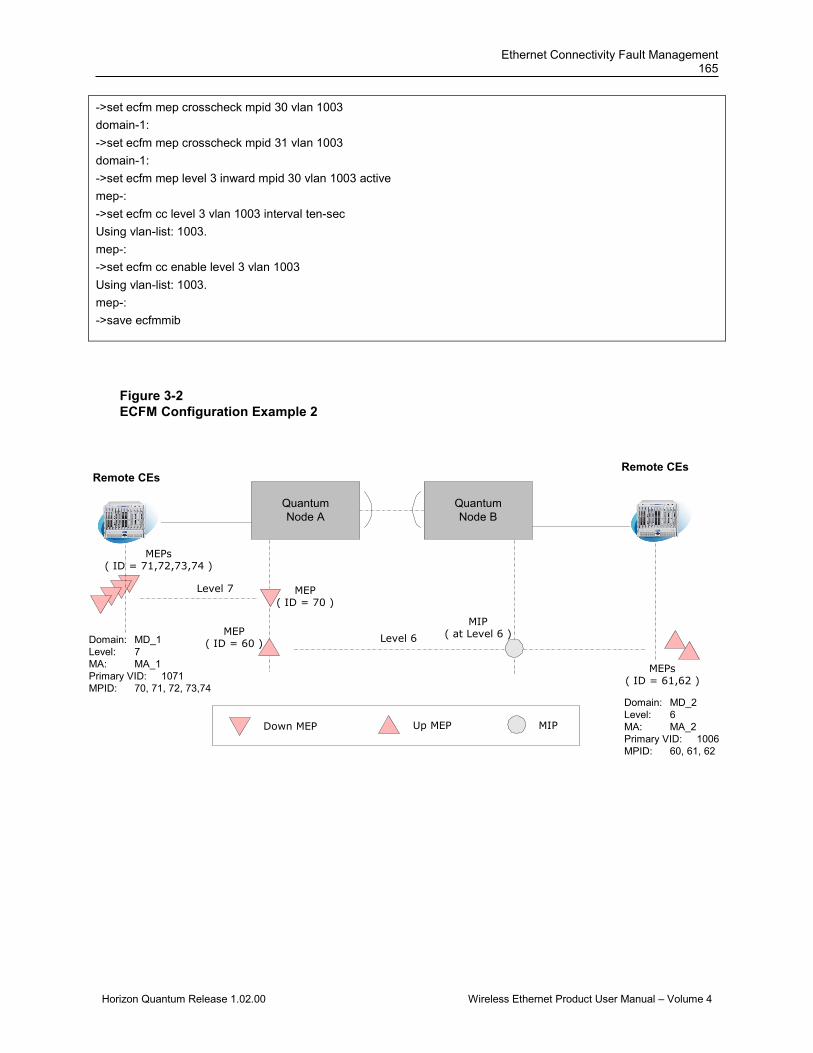
Ethernet Connectivity Fault Management 165
Horizon Quantum Release 1.02.00 Wireless Ethernet Product User Manual – Volume 4
MEP( ID = 70 )
Remote CEsRemote CEs
Level 7
MEPs( ID = 71,72,73,74 )
Domain: MD_1Level: 7MA: MA_1Primary VID: 1071MPID: 70, 71, 72, 73,74
MEP( ID = 60 )
MIP( at Level 6 )Level 6
MEPs( ID = 61,62 )
Domain: MD_2Level: 6MA: MA_2Primary VID: 1006MPID: 60, 61, 62
Down MEP Up MEP MIP
QuantumNode A
QuantumNode B
->set ecfm mep crosscheck mpid 30 vlan 1003 domain-1: ->set ecfm mep crosscheck mpid 31 vlan 1003 domain-1: ->set ecfm mep level 3 inward mpid 30 vlan 1003 active mep-: ->set ecfm cc level 3 vlan 1003 interval ten-sec Using vlan-list: 1003. mep-: ->set ecfm cc enable level 3 vlan 1003 Using vlan-list: 1003. mep-: ->save ecfmmib
Figure 3-2 ECFM Configuration Example 2
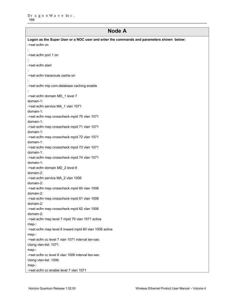
DragonWave Inc. 166
Horizon Quantum Release 1.02.00 Wireless Ethernet Product User Manual – Volume 4
Node A Logon as the Super User or a NOC user and enter the commands and parameters shown below: ->set ecfm on : ->set ecfm port 1 on : ->set ecfm start : ->set ecfm traceroute cache on : ->set ecfm mip ccm-database caching enable : ->set ecfm domain MD_1 level 7 domain-1: ->set ecfm service MA_1 vlan 1071 domain-1: ->set ecfm mep crosscheck mpid 70 vlan 1071 domain-1: ->set ecfm mep crosscheck mpid 71 vlan 1071 domain-1: ->set ecfm mep crosscheck mpid 72 vlan 1071 domain-1: ->set ecfm mep crosscheck mpid 73 vlan 1071 domain-1: ->set ecfm mep crosscheck mpid 74 vlan 1071 domain-1: ->set ecfm domain MD_2 level 6 domain-2: ->set ecfm service MA_2 vlan 1006 domain-2: ->set ecfm mep crosscheck mpid 60 vlan 1006 domain-2: ->set ecfm mep crosscheck mpid 61 vlan 1006 domain-2: ->set ecfm mep crosscheck mpid 62 vlan 1006 domain-2: ->set ecfm mep level 7 mpid 70 vlan 1071 active mep-: ->set ecfm mep level 6 inward mpid 60 vlan 1006 active mep-: ->set ecfm cc level 7 vlan 1071 interval ten-sec Using vlan-list: 1071. mep-: ->set ecfm cc level 6 vlan 1006 interval ten-sec Using vlan-list: 1006. mep-: ->set ecfm cc enable level 7 vlan 1071
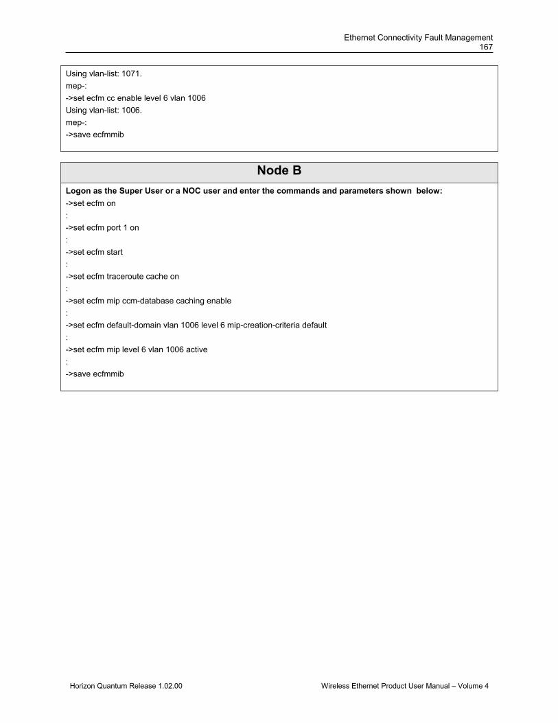
Ethernet Connectivity Fault Management 167
Horizon Quantum Release 1.02.00 Wireless Ethernet Product User Manual – Volume 4
Using vlan-list: 1071. mep-: ->set ecfm cc enable level 6 vlan 1006 Using vlan-list: 1006. mep-: ->save ecfmmib
Node B Logon as the Super User or a NOC user and enter the commands and parameters shown below: ->set ecfm on : ->set ecfm port 1 on : ->set ecfm start : ->set ecfm traceroute cache on : ->set ecfm mip ccm-database caching enable : ->set ecfm default-domain vlan 1006 level 6 mip-creation-criteria default : ->set ecfm mip level 6 vlan 1006 active : ->save ecfmmib

DragonWave Inc. 168
Horizon Quantum Release 1.02.00 Wireless Ethernet Product User Manual – Volume 4
QuantumNode A1
QuantumNode C2
Level 3MEP
( ID = 30 )MEP
( ID = 31 )
QuantumNode A2
QuantumNode B1
QuantumNode B2
QuantumNode C1
MEP( ID = 41 )
MEP( ID = 40 )Level 4
Down MEP Up MEP MIP
Figure 3-3 ECFM Configuration Example 3
Node A1 Logon as the Super User or a NOC user and enter the commands and parameters shown below: ->set ecfm on : ->set ecfm port 1 on : ->set ecfm start : ->set ecfm traceroute cache on : ->set ecfm mip ccm-database caching enable : ->set ecfm domain MD_3 level 3 domain-1: ->set ecfm service MA_3 vlan 1003 domain-1: ->set ecfm mep crosscheck mpid 30 vlan 1003 domain-1: ->set ecfm mep crosscheck mpid 31 vlan 1003 domain-1: ->set ecfm domain MD_4 level 4 domain-2: ->set ecfm service MA_4 vlan 1004 domain-2: ->set ecfm mep crosscheck mpid 40 vlan 1004 domain-2: ->set ecfm mep crosscheck mpid 41 vlan 1004 domain-2: ->set ecfm mep level 3 inward mpid 30 vlan 1003 active mep-: ->set ecfm mep level 4 mpid 40 vlan 1004 active
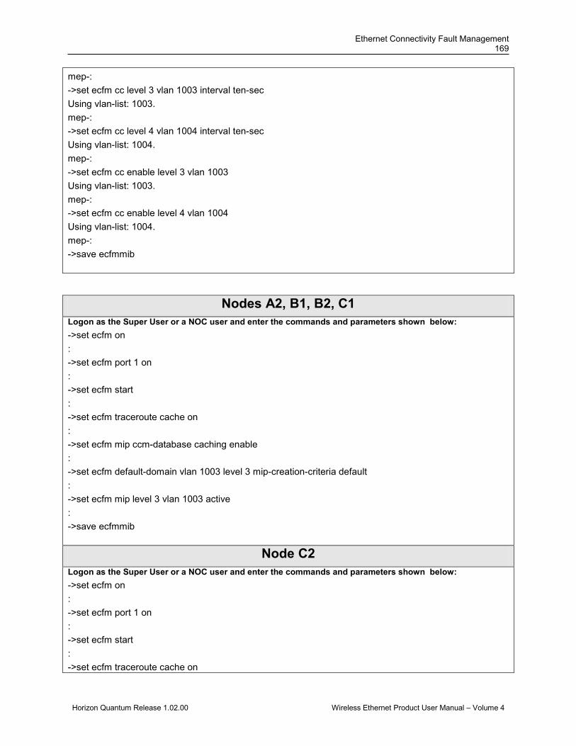
Ethernet Connectivity Fault Management 169
Horizon Quantum Release 1.02.00 Wireless Ethernet Product User Manual – Volume 4
mep-: ->set ecfm cc level 3 vlan 1003 interval ten-sec Using vlan-list: 1003. mep-: ->set ecfm cc level 4 vlan 1004 interval ten-sec Using vlan-list: 1004. mep-: ->set ecfm cc enable level 3 vlan 1003 Using vlan-list: 1003. mep-: ->set ecfm cc enable level 4 vlan 1004 Using vlan-list: 1004. mep-: ->save ecfmmib
Nodes A2, B1, B2, C1 Logon as the Super User or a NOC user and enter the commands and parameters shown below: ->set ecfm on : ->set ecfm port 1 on : ->set ecfm start : ->set ecfm traceroute cache on : ->set ecfm mip ccm-database caching enable : ->set ecfm default-domain vlan 1003 level 3 mip-creation-criteria default : ->set ecfm mip level 3 vlan 1003 active : ->save ecfmmib
Node C2 Logon as the Super User or a NOC user and enter the commands and parameters shown below: ->set ecfm on : ->set ecfm port 1 on : ->set ecfm start : ->set ecfm traceroute cache on
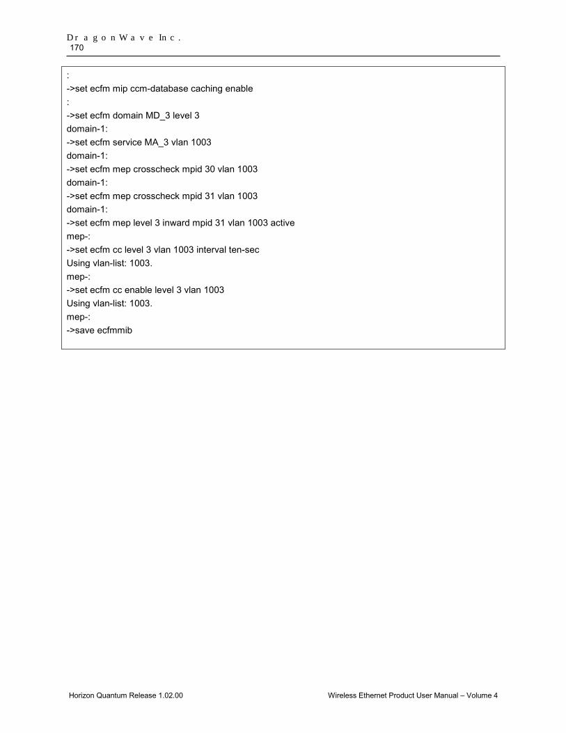
DragonWave Inc. 170
Horizon Quantum Release 1.02.00 Wireless Ethernet Product User Manual – Volume 4
: ->set ecfm mip ccm-database caching enable : ->set ecfm domain MD_3 level 3 domain-1: ->set ecfm service MA_3 vlan 1003 domain-1: ->set ecfm mep crosscheck mpid 30 vlan 1003 domain-1: ->set ecfm mep crosscheck mpid 31 vlan 1003 domain-1: ->set ecfm mep level 3 inward mpid 31 vlan 1003 active mep-: ->set ecfm cc level 3 vlan 1003 interval ten-sec Using vlan-list: 1003. mep-: ->set ecfm cc enable level 3 vlan 1003 Using vlan-list: 1003. mep-: ->save ecfmmib
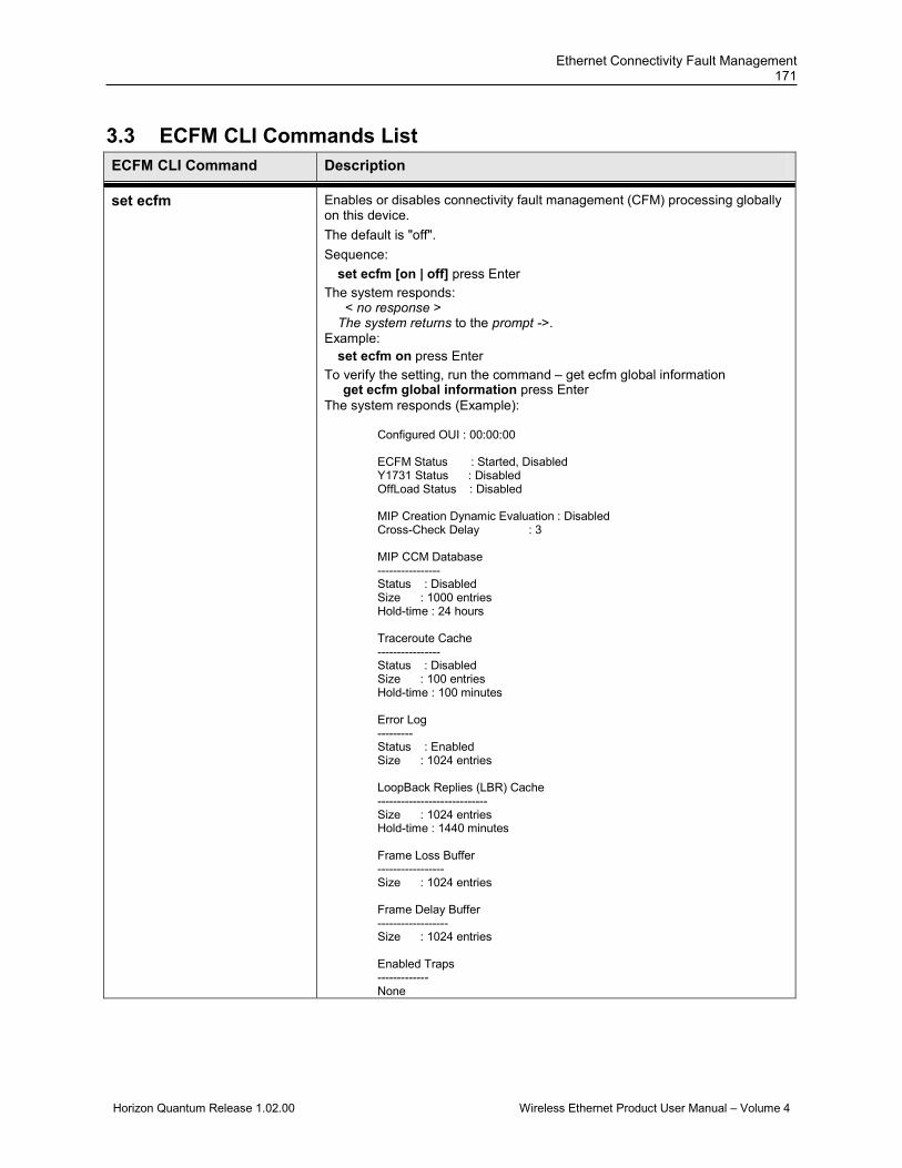
Ethernet Connectivity Fault Management 171
Horizon Quantum Release 1.02.00 Wireless Ethernet Product User Manual – Volume 4
3.3 ECFM CLI Commands List ECFM CLI Command Description
set ecfm Enables or disables connectivity fault management (CFM) processing globally on this device. The default is "off". Sequence:
set ecfm [on | off] press Enter The system responds:
< no response > The system returns to the prompt ->.
Example: set ecfm on press Enter
To verify the setting, run the command – get ecfm global information get ecfm global information press Enter The system responds (Example):
Configured OUI : 00:00:00 ECFM Status : Started, Disabled Y1731 Status : Disabled OffLoad Status : Disabled MIP Creation Dynamic Evaluation : Disabled Cross-Check Delay : 3 MIP CCM Database ---------------- Status : Disabled Size : 1000 entries Hold-time : 24 hours Traceroute Cache ---------------- Status : Disabled Size : 100 entries Hold-time : 100 minutes Error Log --------- Status : Enabled Size : 1024 entries LoopBack Replies (LBR) Cache ---------------------------- Size : 1024 entries Hold-time : 1440 minutes Frame Loss Buffer ----------------- Size : 1024 entries Frame Delay Buffer ------------------ Size : 1024 entries Enabled Traps ------------- None

DragonWave Inc. 172
Horizon Quantum Release 1.02.00 Wireless Ethernet Product User Manual – Volume 4
ECFM CLI Command Description
set ecfm y1731 Enables(on) or disables(off) Y.1731 processing globally on a device. For Y.1731 to be enabled, ecfm should be enabled. When Y.1731 is off, ecfm default protocol is 802.1ag. Sequence:
set ecfm [on | off] press Enter The system responds:
< no response > The system returns to the prompt ->.
set ecfm port Sets the port number that subsequent ecfm commands will apply to. The default is "off". Sequence:
set ecfm port [port number] [on | off] Example: set ecfm port 1 on press Enter The system responds:
port-1 Note: To verify the setting, run the following command : get ecfm port information press Enter The system responds the following information for all ports: ------------------------------ ecfm Status : Enabled LLC Encapsulation : Disabled MEPs Configured : 1 MIPs Configured : 1
set ecfm oui Configure the Organization Unit Identifier (OUI). Organizationally Unique Identifier (OUI) is a 24-bit number that is purchased from the Institute of Electrical and Electronics Engineers. Sequence:
set ecfm oui [xx:yy:zz] press Enter The system responds:
< no response > The system returns to the prompt ->. To verify the setting, run the command – get ecfm global information set ecfm oui 00:07:58 press Enter then get ecfm global information press Enter The system responds: Configured OUI : 00:07:58 (……00:07:58 is the OUI belonging to DragonWave)
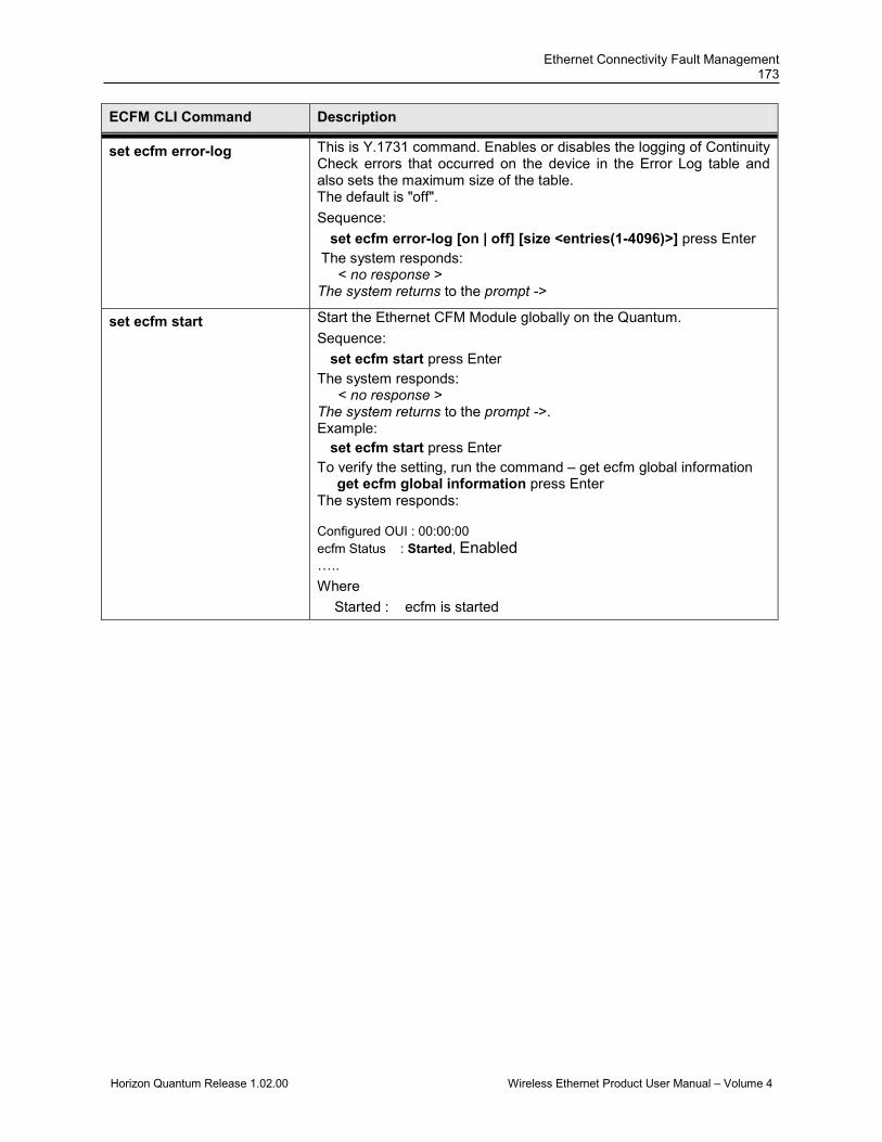
Ethernet Connectivity Fault Management 173
Horizon Quantum Release 1.02.00 Wireless Ethernet Product User Manual – Volume 4
ECFM CLI Command Description
set ecfm error-log This is Y.1731 command. Enables or disables the logging of Continuity Check errors that occurred on the device in the Error Log table and also sets the maximum size of the table. The default is "off". Sequence:
set ecfm error-log [on | off] [size <entries(1-4096)>] press Enter The system responds:
< no response > The system returns to the prompt ->
set ecfm start Start the Ethernet CFM Module globally on the Quantum. Sequence:
set ecfm start press Enter The system responds:
< no response > The system returns to the prompt ->. Example:
set ecfm start press Enter To verify the setting, run the command – get ecfm global information get ecfm global information press Enter The system responds: Configured OUI : 00:00:00 ecfm Status : Started, Enabled ….. Where
Started : ecfm is started
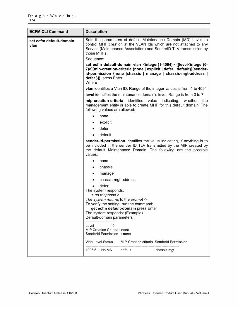
DragonWave Inc. 174
Horizon Quantum Release 1.02.00 Wireless Ethernet Product User Manual – Volume 4
ECFM CLI Command Description
set ecfm default-domain vlan
Sets the parameters of default Maintenance Domain (MD) Level, to control MHF creation at the VLAN Ids which are not attached to any Service (Maintenance Association) and SenderID TLV transmission by those MHFs. Sequence: set ecfm default-domain vlan <integer(1-4094)> ([level<integer(0-7)>][mip-creation-criteria {none | explicit | defer | default}][sender-id-permission {none |chassis | manage | chassis-mgt-address | defer }]) press Enter Where vlan identifies a Vlan ID. Range of the integer values is from 1 to 4094 level identifies the maintenance domain’s level. Range is from 0 to 7. mip-creation-criteria identifies value indicating, whether the management entity is able to create MHF for this default domain. The following values are allowed:
• none • explicit • defer • default
sender-id-permission identifies the value indicating, if anything is to be included in the sender ID TLV transmitted by the MIP created by the default Maintenance Domain. The following are the possible values:
• none • chassis • manage • chassis-mgt-address • defer
The system responds: < no response >
The system returns to the prompt ->. To verify the setting, run the command: get ecfm default-domain press Enter The system responds: (Example) Default-domain parameters -------------------------- Level : 0 MIP Creation Criteria : none SenderId Permission : none -------------------------------------------------------------------------------- Vlan Level Status MIP-Creation criteria SenderId Permission -------------------------------------------------------------------------------- 1006 6 No MA default chassis-mgt

Ethernet Connectivity Fault Management 175
Horizon Quantum Release 1.02.00 Wireless Ethernet Product User Manual – Volume 4
ECFM CLI Command Description
set ecfm default-domain global
Defines or deletes a connectivity fault management (CFM) Maintenance Domain (MD) at a particular maintenance level and puts the device in Ethernet CFM configuration mode, where parameters specific to the maintenance domain can be set. Sequence:
set ecfm default-domain global levelid <(0-7)> press Enter Where levelid identifies the maintenance domain’s level. Range is from 0 to 7. The system responds:
< no response > The system returns to the prompt ->. Example: set ecfm default-domain global levelid 7 press Enter To verify the setting, run the command: get ecfm default-domain press Enter The system responds: (Example) Default-domain parameters -------------------------- Level : 7 MIP Creation Criteria : none SenderId Permission : none ……
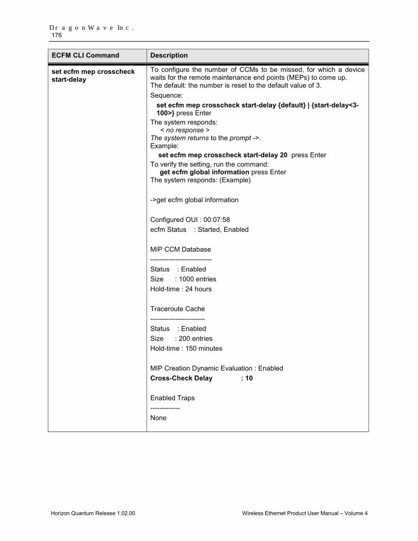
DragonWave Inc. 176
Horizon Quantum Release 1.02.00 Wireless Ethernet Product User Manual – Volume 4
ECFM CLI Command Description
set ecfm mep crosscheck start-delay
To configure the number of CCMs to be missed, for which a device waits for the remote maintenance end points (MEPs) to come up. The default: the number is reset to the default value of 3. Sequence:
set ecfm mep crosscheck start-delay {default} | {start-delay<3-100>} press Enter
The system responds: < no response >
The system returns to the prompt ->. Example:
set ecfm mep crosscheck start-delay 20 press Enter To verify the setting, run the command: get ecfm global information press Enter The system responds: (Example) ->get ecfm global information Configured OUI : 00:07:58 ecfm Status : Started, Enabled MIP CCM Database --------------------------- Status : Enabled Size : 1000 entries Hold-time : 24 hours Traceroute Cache ------------------------ Status : Enabled Size : 200 entries Hold-time : 150 minutes MIP Creation Dynamic Evaluation : Enabled Cross-Check Delay : 10 Enabled Traps ------------- None

Ethernet Connectivity Fault Management 177
Horizon Quantum Release 1.02.00 Wireless Ethernet Product User Manual – Volume 4
ECFM CLI Command Description
set ecfm traceroute cache Enables Linktrace replies (LTR) caching. The default: it is disabled. Sequence:
set ecfm traceroute [on | off] press Enter The system responds:
< no response > The system returns to the prompt ->.
To verify the setting, run the command: get ecfm global information press Enter The system responds: (Example) ….. Traceroute Cache ------------------------ Status : Enabled Size : 200 entries Hold-time : 150 minutes
set ecfm traceroute cachesize
Sets maximum size for the Linktrace reply (LTR) table. Traceroute caching should be enabled and cache should be empty. The default : Sequence:
set ecfm traceroute cachesize {default | <integer(1-4095)> } press Enter
The system responds: < no response >
The system returns to the prompt ->. Example: See the example in the command – set ecfm traceroute cache.
set ecfm traceroute cache holdtime
Sets Linktrace replies (LTR Table) maximum age. The default : hold time is 100 minutes. Sequence:
set ecfm traceroute holdtime {default | integer(1-65535)} press Enter
The system responds: < no response >
The system returns to the prompt ->. Example: See the example in the command – set ecfm traceroute cache .

DragonWave Inc. 178
Horizon Quantum Release 1.02.00 Wireless Ethernet Product User Manual – Volume 4
ECFM CLI Command Description
set ecfm mip ccm-database caching
Enable or disable Ethernet CFM MIP-CCM database caching. Sequence:
set ecfm mip ccm-database caching {enable | disable} press Enter
The system responds: < no response >
The system returns to the prompt ->. Example: set ecfm mip ccm-database caching enable press Enter To verify the setting, run the command: get ecfm global information press Enter The system responds: (Example) ->get ecfm global information Configured OUI : 00:07:58 ecfm Status : Started, Enabled MIP CCM Database --------------------------- Status : Enabled Size : 1000 entries Hold-time : 24 hours ……
set ecfm mip ccm-database size
Sets the number of entries in the ecfm ccm-database, in hours. The default is 1000 entries. Sequence:
set ecfm mip ccm-database size [<entries(1000-10000)>] press Enter
The system responds: < no response >
The system returns to the prompt ->. Example: See the example in the command – set ecfm mip ccm-database caching.

Ethernet Connectivity Fault Management 179
Horizon Quantum Release 1.02.00 Wireless Ethernet Product User Manual – Volume 4
ECFM CLI Command Description
set ecfm mip ccm-database hold-time
Sets the hold time for the ecfm ccm-database, in hours. The default is 24 hours. Sequence:
set ecfm mip ccm-database holdtime [<hours>(24-48)] press Enter
The system responds: < no response >
The system returns to the prompt ->. Example: See the example in the command – set ecfm mip ccm-database cacheing.
set ecfm domain Defines or selects a connectivity fault management (CFM) Maintenance Domain (MD) at a particular maintenance level, where parameters specific to the maintenance domain can be set. Sequence:
set ecfm domain <domain-name(1..20)> level <level-id(0-7)> [delete] press Enter
Where domain-name identifies the domain. Character string has a maximum limit of twenty characters. level identifies the maintenance domain’s level. Range is from 0 to 7. Example: set ecfm domain test_md_1 level 1 press Enter The system responds:
domain-1: -> Where domain-n: n is the domain index, which corresponds to the Index column entry in response to the get ecfm domain command.
If there is no domain named test_md_1 and level is 1, the system will create a domain with the parameters: test_md_1 and 1. If a domain with this name already exists, but at a different level, the system will respond with an error message. If there is a domain that exists in the system with the same level, the system will select this domain as the current setting domain. It is necessary to use this command before calling the following commands:
• set ecfm mip-creation-criteria
• set ecfm service
• set mep crosscheck mpid
• set ecfm mep archive-hold-time Note: Quantum release 1.0 only supports character string type domain names.

DragonWave Inc. 180
Horizon Quantum Release 1.02.00 Wireless Ethernet Product User Manual – Volume 4
ECFM CLI Command Description
set ecfm mep archive-hold-time
Sets the amount of in minutes time such that information from a MEP is kept in the CC database before they are purged. Defaults set to 100 minutes. Sequence:
set ecfm mep archive-hold-time {<minutes(100-65535) | default } press Enter
The system responds: < no response >
The system returns to the prompt ->. Example: set ecfm domain MD_level_7 level 7 press Enter set ecfm mep archive-hold-time 170 press Enter To verify the setting, run the command – get ecfm domain get ecfm domain press Enter The system responds: No Domain Index Level Services Archive(min) 1 MD_level_7 1 7 2 150

Ethernet Connectivity Fault Management 181
Horizon Quantum Release 1.02.00 Wireless Ethernet Product User Manual – Volume 4
ECFM CLI Command Description
set ecfm service Configures the provided Service (Maintenance Association) at the specified vlan. User can configure ICC and UMC when Y.1731 is enabled. Sequence: set ecfm service <{[config] <service_name> [{icc <icc_code> umc <umc_code>] [vlan <vlan-id(1-4094)>] [mip-creation-criteria {none | default | explicit | defer}] [sender-id-permission {none | chassis | manage | chassis-mgt-address | defer}]}>| <{delete <service_name> press Enter Where service_name identifies the maintenance association. Maximum limit of the Character string is up to 20 characters. icc_code identifies ITU carrier code. umc_code identifies Unique MEGID code. vlan-id specifics Vlan ID. mip-creation-criteria identifies value indicating, whether the management entity is able to create MHF for this default domain. The following values are allowed:
• none • explicit • defer • default
sender-id-permission identifies the value indicating, if anything is to be included in the sender ID TLV transmitted by the MIP created by the default Maintenance Domain. The following are the possible values:
• none • chassis • manage • chassis-mgt-address • defer
Examples: To creating a service with 802.1ag protocol:
set ecfm service ma_one vlan 100 mip-creation-criteria default sender-id-permission none press Enter
To creating a service with Y.1731 protocol: set ecfm service ma_one icc icc001 umc umc00 vlan 100 mip-creation-criteria default sender-id-permission none press Enter To verify the setting, run the command: get ecfm service Note: Quantum 1.0 release only supports char-string type service name.

DragonWave Inc. 182
Horizon Quantum Release 1.02.00 Wireless Ethernet Product User Manual – Volume 4
ECFM CLI Command Description
set ecfm mep crosscheck mpid
Statically defines maintenace end point (MEP) or remote MEP. (MEP is defined in a list of MEPIDs of a service associated with a provided VLAN) Sequence: set ecfm mep crosscheck mpid <integer(1-8191)> [delete|define] [vlan <integer(1-4094)>] press Enter Where mpid <integer(1-8191)> identifies MEP identifier. vlan <integer(1-4094)> specifics a Vlan ID Examples: To define a mep crosscheck / remote MEP
set ecfm mep crosscheck mpid 70 vlan 100 press Enter To delete a mep crosscheck / remote MEP
set ecfm mep crosscheck mpid 70 delete vlan 100 press Enter The system responds:
< no response > The system returns to the prompt ->.
set ecfm mep level Configures or deletes a local Maintenance end point (MEP) (Sets an port as a domain boundary (edge)by defining it as a MEP), and sets direction for the MEP.) Sequence:
set ecfm mep level [<0-7>] [delete] [inward] [mpid <id(1-8191)>] [vlan<vlan-id(1-4094)>] [active] press Enter
Where level [<0-7>] identifies the maintenance domain’s level. Range is from 0 to 7. delete is to delete this local MEP. inward specifies the direction. By default, “outward” is created, that is “Down MEP”. mpid <id(1-8191) is the MEP identifier. vlan<vlan-id(1-4094) specifics a Vlan ID. active specifies the MEP’s operational status. By default, MEP is not active. The system responds: mep-: mep-: means that current input status is in the mep-status. This command is required before issuing one of the following commands:
• set ecfm mep-capability level
• set ecfm ccm-unicast-mac

Ethernet Connectivity Fault Management 183
Horizon Quantum Release 1.02.00 Wireless Ethernet Product User Manual – Volume 4
ECFM CLI Command Description
set ecfm mep-capability level
This is an Y.1731 command. Enable (on) or disable (off) the capabilities of all the MEPs in a MA at the level and vlan. Defaults to enable if on/off not specified. Sequence: set ecfm mep-capability level {<level-id(0-7)> | level-list} [on|off] [vlan {<vlan-id(1-4094)> | vlan-list}]([ping] [muliticast-ping] [turnaround-delay] [rdi]) press Enter Where level {<level-id(0-7) identifies the maintenance domain’s level. Range is from 0 to 7. level-list identifies a list of levels. [on|off] is to enable(on) or disable(off) the MEP’s capabilities. vlan {<vlan-id(1-4094)> specifics a Vlan ID. vlan-list identifies a list of Vlan IDs. ping identifies that the loopback(ping) capability is enabled or disabled. The default capabilities include ping. multicast-ping identifies that the multicast loopback(ping) capability is enabled or disabled. turnaround-delay identifies that the two-way frame delay measurement capability is enabled or disabled. rdi identifies that the remote defect indication capability is enabled or disabled. The default capabilities include rdi. Example:
set ecfm mep level 7 mpid 70 1071 active press Enter then
set ecfm mep-capability level 7 vlan 1071 ping multicast-ping turnaround-delay rdi press Enter
To verify the setting, run the command: get ecfm maintenance-points local detail mpid 70 MPID: 70 MdLevel: 7 VLAN: 1071 Dir: Down ------------------------------------------------ Out-Of-Service : Disabled RDI Capability : Enabled Loopback Capability : Enabled Multicast LBM Reception Capability : Enabled Multicast TST Reception Capability : Disabled One-Way DM Reception Capability : Disabled DMR Optional Fields : Enabled Delay Threshold : - AIS Capability : Disabled AIS Condition : Disabled LCK Condition : Disabled LCK Client Mac Address : 00:00:00:00:00:00 AIS Client Mac Address : 00:00:00:00:00:00 Near-End Loss Threshold : - Far-End Loss Threshold : -
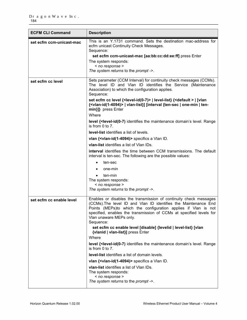
DragonWave Inc. 184
Horizon Quantum Release 1.02.00 Wireless Ethernet Product User Manual – Volume 4
ECFM CLI Command Description
set ecfm ccm-unicast-mac This is an Y.1731 command. Sets the destination mac-address for ecfm unicast Continuity Check Messages. Sequence:
set ecfm ccm-unicast-mac [aa:bb:cc:dd:ee:ff] press Enter The system responds:
< no response > The system returns to the prompt ->.
set ecfm cc level
Sets parameter (CCM Interval) for continuity check messages (CCMs). The level ID and Vlan ID identifies the Service (Maintenance Association) to which the configuration applies. Sequence: set ecfm cc level {<level-id(0-7)> | level-list} {<default > | [vlan {<vlan-id(1-4094)> | vlan-list}] [interval {ten-sec | one-min | ten-min}]} press Enter Where level {<level-id(0-7) identifies the maintenance domain’s level. Range is from 0 to 7. level-list identifies a list of levels. vlan {<vlan-id(1-4094)> specifics a Vlan ID. vlan-list identifies a list of Vlan IDs. interval identifies the time between CCM transmissions. The default interval is ten-sec. The following are the possible values:
• ten-sec • one-min • ten-min
The system responds: < no response >
The system returns to the prompt ->.
set ecfm cc enable level Enables or disables the transmission of continuity check messages (CCMs).The level ID and Vlan ID identifies the Maintenance End Points (MEPs)to which the configuration applies if Vlan is not specified, enables the transmission of CCMs at specified levels for Vlan unaware MEPs only. Sequence:
set ecfm cc enable level [disable] {levelid | level-list} [vlan {vlanid | vlan-list}] press Enter
Where level {<level-id(0-7) identifies the maintenance domain’s level. Range is from 0 to 7. level-list identifies a list of domain levels. vlan {<vlan-id(1-4094)> specifics a Vlan ID. vlan-list identifies a list of Vlan IDs. The system responds:
< no response > The system returns to the prompt ->.

Ethernet Connectivity Fault Management 185
Horizon Quantum Release 1.02.00 Wireless Ethernet Product User Manual – Volume 4
ECFM CLI Command Description
set ecfm mip dynamic evaluation
Enables or Disables the implicit evaluation and creation of a MIP.
set ecfm mip level Configures a Maintenance intermediate point (MIP) at the specified level and vlan on an interface. active - makes MIP operationally active, by default MIP is configured as operationally active. Sequence:
set ecfm mip level [delete] <level-id(0-7)> vlan <vlan-id(1-4094)> [active] press Enter
Where level {<level-id(0-7) identifies the maintenance domain’s level. Range is from 0 to 7. vlan {<vlan-id(1-4094)> specifics a Vlan ID. active specifies the MEP’s operational status. By default, MIP is not active. The system responds:
< no response > The system returns to the prompt ->.
set ecfm associate vlan-id Associate a list of Vlan-Ids to a Primary Vlan. Sequence:
set ecfm associate vlan-id {vlan-id | vlan-list} primary-vlan-id <vlan-id(1-4094)> press Enter Where associate vlan {<vlan-id(1-4094)> | vlan-list specifics a Vlan ID or a list of Vlan IDs to which Primary Vlan ID must be associated. primary-vlan-id idenfies Primary Vlan ID. Example: set ecfm associate 1001,1002,1003,1004 primary-vlan-id 1071 The system responds:
< no response > The system returns to the prompt ->.
save ecfmmib Perform this command to save ecfm settings to FLASH. This command does not restart the system and does not put any new settings into effect. Sequence:
save ecfmmib press Enter The system responds:
Warning: This command could take up to 4 minutes to finish. Mib saved successfully.
Note: To save ecfm settings, ecfm must be ‘on’ status. If ecfm is in ‘off’ status, no ecfm setting will be saved into the Flash.

DragonWave Inc. 186
Horizon Quantum Release 1.02.00 Wireless Ethernet Product User Manual – Volume 4
ECFM CLI Command Description
get ecfm configuration-errors
Displays the ecfm configuration-related errors (CFM leak, Conflicting VlanIds, Excessive Levels, etc). The default will show all port’s error message if error configuration exists. Sequence:
get ecfm configuration-errors [switchport <port-num>] press Enter
Where switchport <port-num> specifics a port number The system responds error message if error configuration exists. The ecfm configuration error type:
• CFM Leak • Conflicting Vids • Excessive Levels • Overlapped Levels
Example: ->get ecfm configuration-errors Configuration Errors --------------------------------------------- interface gigabitethernet: 0/1 VLAN : 1005 Excessive Levels --------------------------------------------- interface gigabitethernet: 0/1 VLAN : 1006 Excessive Levels --------------------------------------------- interface gigabitethernet: 0/1 VLAN : 1071 Excessive Levels
get ecfm default-domain Displays the global Default-domain parameters along with the modified parameters corresponding to a VLAN. Sequence: get ecfm default-domain press Enter The system responds: Default-domain parameters -------------------------- Level : 0 MIP Creation Criteria : none SenderId Permission : none -------------------------------------------------------------------------------- Vlan Level Status MIP-Creation criteria SenderId Permission -------------------------------------------------------------------------------- 1006 6 No MA default chassis-mgt
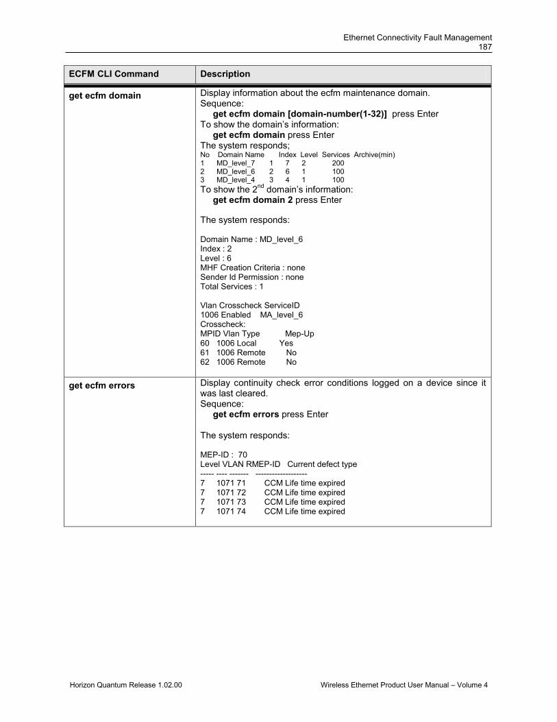
Ethernet Connectivity Fault Management 187
Horizon Quantum Release 1.02.00 Wireless Ethernet Product User Manual – Volume 4
ECFM CLI Command Description
get ecfm domain Display information about the ecfm maintenance domain. Sequence: get ecfm domain [domain-number(1-32)] press Enter To show the domain’s information: get ecfm domain press Enter The system responds; No Domain Name Index Level Services Archive(min) 1 MD_level_7 1 7 2 200 2 MD_level_6 2 6 1 100 3 MD_level_4 3 4 1 100 To show the 2nd domain’s information: get ecfm domain 2 press Enter The system responds: Domain Name : MD_level_6 Index : 2 Level : 6 MHF Creation Criteria : none Sender Id Permission : none Total Services : 1 Vlan Crosscheck ServiceID 1006 Enabled MA_level_6 Crosscheck: MPID Vlan Type Mep-Up 60 1006 Local Yes 61 1006 Remote No 62 1006 Remote No
get ecfm errors Display continuity check error conditions logged on a device since it was last cleared. Sequence: get ecfm errors press Enter The system responds: MEP-ID : 70 Level VLAN RMEP-ID Current defect type ----- ---- ------- ------------------- 7 1071 71 CCM Life time expired 7 1071 72 CCM Life time expired 7 1071 73 CCM Life time expired 7 1071 74 CCM Life time expired
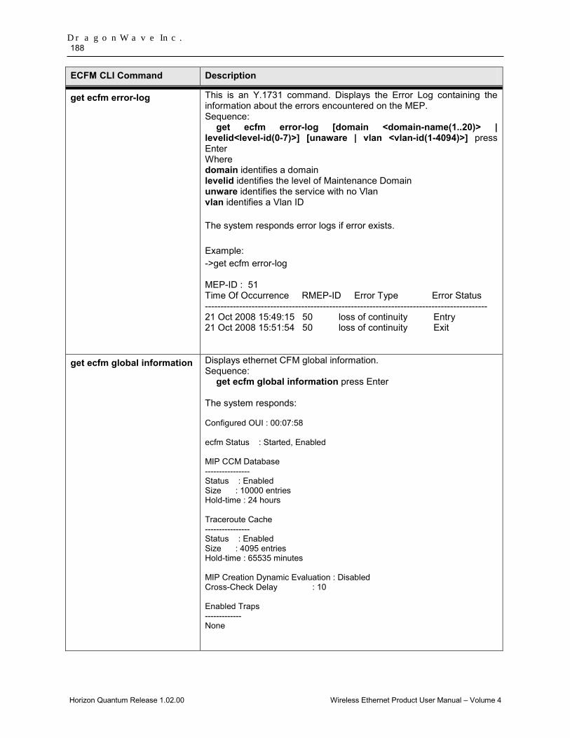
DragonWave Inc. 188
Horizon Quantum Release 1.02.00 Wireless Ethernet Product User Manual – Volume 4
ECFM CLI Command Description
get ecfm error-log This is an Y.1731 command. Displays the Error Log containing the information about the errors encountered on the MEP. Sequence:
get ecfm error-log [domain <domain-name(1..20)> | levelid<level-id(0-7)>] [unaware | vlan <vlan-id(1-4094)>] press Enter Where domain identifies a domain levelid identifies the level of Maintenance Domain unware identifies the service with no Vlan vlan identifies a Vlan ID The system responds error logs if error exists. Example: ->get ecfm error-log MEP-ID : 51 Time Of Occurrence RMEP-ID Error Type Error Status ------------------------------------------------------------------------------------------- 21 Oct 2008 15:49:15 50 loss of continuity Entry 21 Oct 2008 15:51:54 50 loss of continuity Exit
get ecfm global information Displays ethernet CFM global information. Sequence:
get ecfm global information press Enter
The system responds: Configured OUI : 00:07:58 ecfm Status : Started, Enabled MIP CCM Database ---------------- Status : Enabled Size : 10000 entries Hold-time : 24 hours Traceroute Cache ---------------- Status : Enabled Size : 4095 entries Hold-time : 65535 minutes MIP Creation Dynamic Evaluation : Disabled Cross-Check Delay : 10 Enabled Traps ------------- None

Ethernet Connectivity Fault Management 189
Horizon Quantum Release 1.02.00 Wireless Ethernet Product User Manual – Volume 4
ECFM CLI Command Description
get ecfm loopback cache Displays the Loopback transactions related information. Sequence:
get ecfm loopback cache [brief] [level <level-id(0-7)>][unaware | vlan <vlan-id(1-4094)>] press Enter Where level identifies the level of Maintenance Domain unware identifies the service with no Vlan vlan identifies a Vlan ID The system responds: (Example) ->get ecfm loopback cache Interface : gigabitethernet 0/1 MEP-ID : 40 Level : 4 VLAN-ID : 0 ping statistics with 00:10:94:00:00:11 source mac bytesreceived seq no time to receive error type ------------------ -------------- ------ --------------- ---------- 00:10:94:00:00:11 30 0 50ms none 00:10:94:00:00:11 30 1 50ms none 00:10:94:00:00:11 30 2 50ms none 00:10:94:00:00:11 30 3 50ms none 00:10:94:00:00:11 30 4 50ms none packets sent = 5, packets received = 5, packets lost = 0 (0.000% loss), unexpected received = 0, checksum errors = 0, bad messages received = 0, duplicates received = 0 rtt min/avg/max = 50/50/50 ms

DragonWave Inc. 190
Horizon Quantum Release 1.02.00 Wireless Ethernet Product User Manual – Volume 4
ECFM CLI Command Description
get ecfm maintenance-point local
Displays the brief information about maintenance points configured on a device. Sequence:
get ecfm maintenance-point local [mep | mip] [switchport <port-num>] | domain <domain_name> | level<id(0-7)>] press Enter Where mep | mip identifies the maintenance point’s type switchport identifies the port number domain identifies a domain level identifies the level of Maintenance Domain The system responds: (Example) ->get ecfm maintenance-point local ----------------------------------------------------------------- MPID DomainName Level VLAN Type Port MAC CC-Status ServiceName Dir MP-Status ----------------------------------------------------------------- 40 MD_4 4 0 MEP 1 00:07:58:80:a3:37 Enabled MA_4 Down Active 60 MD_6 6 1006 MEP 1 00:07:58:80:a3:37 Enabled MA_6 Up Active 70 MD_7 7 1071 MEP 1 00:07:58:80:a3:37 Enabled MA_7_1 Down Active 700 MD_7 7 1101 MEP 1 00:07:58:80:a3:37 Enabled MA_7_2 Down Active

Ethernet Connectivity Fault Management 191
Horizon Quantum Release 1.02.00 Wireless Ethernet Product User Manual – Volume 4
ECFM CLI Command Description
get ecfm maintenance-points local detail
Displays the detailed information about the maintenance end points(MEP) locally configured on the device. The information includes thevarious MEPs capabilities, states, threshold values, etc. Sequence:
get ecfm maintenance-points local detail {mpid<mepid(1-8092)> | mac <aa:aa:aa:aa:aa:aa>} [domain <domain_name> | level<level-id(0-7)>] [unaware | vlan <integer(1-4094)>] press Enter Where mpid identifies the MEP identifier mac identifies the MEP’s mac address domain identifies a domain level identifies the level of Maintenance Domain unware identifies the service with no Vlan vlan identifies a Vlan ID Example: ->get ecfm maintenance-points local detail mpid 70 The system responds: (Example) MPID: 70 MdLevel: 7 VLAN: 1071 Dir: Down ------------------------------------------------ Out-Of-Service : Disabled RDI Capability : Enabled Loopback Capability : Enabled Multicast LBM Reception Capability : Enabled Multicast TST Reception Capability : Disabled One-Way DM Reception Capability : Disabled DMR Optional Fields : Disabled Delay Threshold : - AIS Capability : Disabled AIS Condition : Disabled LCK Condition : Disabled LCK Client Mac Address : 00:00:00:00:00:00 AIS Client Mac Address : 00:00:00:00:00:00 Near-End Loss Threshold : - Far-End Loss Threshold : -
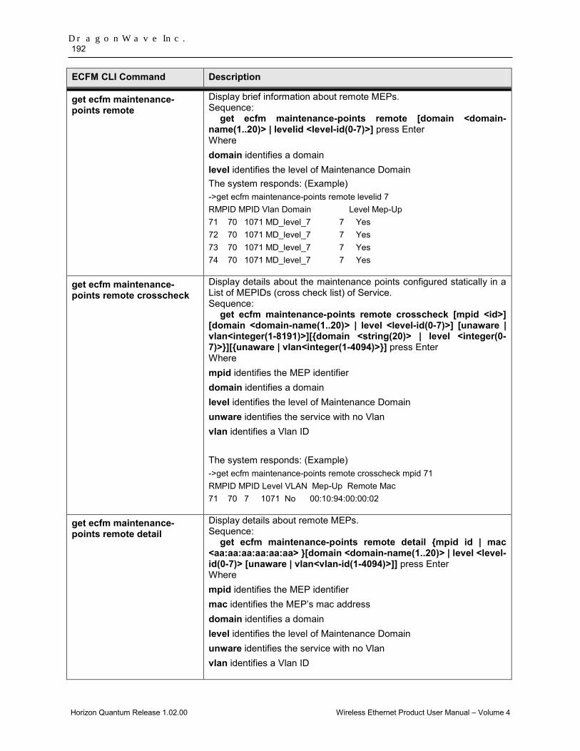
DragonWave Inc. 192
Horizon Quantum Release 1.02.00 Wireless Ethernet Product User Manual – Volume 4
ECFM CLI Command Description
get ecfm maintenance-points remote
Display brief information about remote MEPs. Sequence:
get ecfm maintenance-points remote [domain <domain-name(1..20)> | levelid <level-id(0-7)>] press Enter Where domain identifies a domain level identifies the level of Maintenance Domain The system responds: (Example) ->get ecfm maintenance-points remote levelid 7 RMPID MPID Vlan Domain Level Mep-Up 71 70 1071 MD_level_7 7 Yes 72 70 1071 MD_level_7 7 Yes 73 70 1071 MD_level_7 7 Yes 74 70 1071 MD_level_7 7 Yes
get ecfm maintenance-points remote crosscheck
Display details about the maintenance points configured statically in a List of MEPIDs (cross check list) of Service. Sequence:
get ecfm maintenance-points remote crosscheck [mpid <id>] [domain <domain-name(1..20)> | level <level-id(0-7)>] [unaware | vlan<integer(1-8191)>][{domain <string(20)> | level <integer(0-7)>}][{unaware | vlan<integer(1-4094)>}] press Enter Where mpid identifies the MEP identifier domain identifies a domain level identifies the level of Maintenance Domain unware identifies the service with no Vlan vlan identifies a Vlan ID The system responds: (Example) ->get ecfm maintenance-points remote crosscheck mpid 71 RMPID MPID Level VLAN Mep-Up Remote Mac 71 70 7 1071 No 00:10:94:00:00:02
get ecfm maintenance-points remote detail
Display details about remote MEPs. Sequence:
get ecfm maintenance-points remote detail {mpid id | mac <aa:aa:aa:aa:aa:aa> }[domain <domain-name(1..20)> | level <level-id(0-7)> [unaware | vlan<vlan-id(1-4094)>]] press Enter Where mpid identifies the MEP identifier mac identifies the MEP’s mac address domain identifies a domain level identifies the level of Maintenance Domain unware identifies the service with no Vlan vlan identifies a Vlan ID

Ethernet Connectivity Fault Management 193
Horizon Quantum Release 1.02.00 Wireless Ethernet Product User Manual – Volume 4
ECFM CLI Command Description
get ecfm mip-ccm-database Displays the ecfm MIP CCM Database. Sequence:
get ecfm mip-ccm-database [vlanid <vlan-id(1-4094)>] [macaddress <aa:aa:aa:aa:aa:aa>] [switchport <port-num>] press Enter Where vlan identifies a Vlan ID mac identifies the MEP’s mac address switchport identifies a port number The system responds: (Example) ->get ecfm mip-ccm-database --------------------------------- Vlan Mac Address Port --------------------------------- 1006 00:10:94:00:00:09 1 1006 00:10:94:00:00:0a 1

DragonWave Inc. 194
Horizon Quantum Release 1.02.00 Wireless Ethernet Product User Manual – Volume 4
ECFM CLI Command Description
get ecfm service Display information about Ethernet CFM Service (Maintenance Association). Sequence: get ecfm service [service-number(1-32) ] press Enter Examples: To show service brief information: get ecfm service press Enter The system responds: No ServiceName Index Primary-Vlan Level MEPs CCM Interval 1 MA_7_1 1 1071 7 5 10 seconds 2 MA_7_2 2 1072 7 4 10 seconds 3 MA_y1731_6 1 1006 6 3 10 seconds 4 MA_y1731_5 1 1005 5 2 10 seconds 5 MA_y1731_4 1 0 4 5 10 seconds To show the 2nd service’s information: get ecfm service 2 press Enter The system responds: Service Name : MA_7_2 Domain Name : MEG_y1731_7 Index : 2 Primary Vid : 1072 Level : 7 MHF Creation Criteria : defer Sender Id Permission : defer CC Role : fault management ICC Code : icc007 UMC Code : umc002 Total MEPs : 4 Primary Vlan Associations : 1101, 1102, 1103, 1104, 1105 Crosscheck status : Enabled Crosscheck: MPID Vlan Type Mep-Up Mac Address 700 1101 Local Yes 00:07:58:00:a3:37 701 1101 Remote No Not learned 702 1101 Remote No Not learned 703 1101 Remote No Not learned

Ethernet Connectivity Fault Management 195
Horizon Quantum Release 1.02.00 Wireless Ethernet Product User Manual – Volume 4
ECFM CLI Command Description
get ecfm statistics Displays ecfm statistics for all or a specified port (1-9). Sequence: get ecfm statistics [eth-if <port>] press Enter The system responds this message for all ports: (Example) ->get ecfm statistics --------------------------------------------------------- Global Counters --------------------------------------------------------- Memory Allocation Failed : 0 Buffer Allocation Failed : 0 Module was Enabled : 2 Module was Disabled : 1 No defect occured in MEP : 1 RDI defect occured in MEP : 74 MACStatus defect occured in MEP : 0 Remote CCM defect occured in MEP : 217 Error CCM defect occured in MEP : 0 Xconn defect occured in MEP : 0 ------------------------------------------- interface gigabitethernet 0/1 Counters ------------------------------------------- Transmitted CFM PDU :3160 Received CFM PDU :10076 Transmitted CCM PDU :3160 Received CCM PDU :7676 Transmitted LBM PDU :0 Received LBM PDU :0 Transmitted LBR PDU :0 Received LBR PDU :0 Transmitted LTM PDU :0 Received LTM PDU :0 Transmitted LTR PDU :0 Received LTR PDU :0 …… Transmitted EXM PDU :0 Received EXM PDU :0 Transmitted EXR PDU :0 Received EXR PDU :0 Bad CFM PDU Received : 0 CFM PDU Forwarded : 3188 CFM PDU Discarded : 0 CFM PDU Transmission Failures : 0 ------------------------------------------------------- MPID: 70 MdLevel: 7 VLAN: 1071 Dir: Down CCM PDU Transmitted : 792 LBR PDU Transmitted : 0 LBR PDU Received : 0 TST PDU Transmitted : 0 TST PDU Received : 0 Out-of-sequence CCM PDU Received : 11 Unexpected LTR PDU Received : 0 Out-of-order LBR PDU Received : 0 Bad LBR MSDU Received : 0 Bit-errored LBR PDU Received : 0 Bit-errored TST PDU Received : 0 -------------------------------------------------------

DragonWave Inc. 196
Horizon Quantum Release 1.02.00 Wireless Ethernet Product User Manual – Volume 4
ECFM CLI Command Description
get ecfm traceroute-cache Display details about traceroute cache. (Traceroute cache displays LTR replies corresponding to each LTM transaction). Sequence: get ecfm traceroute-cache press Enter The system responds: (Example) ->get ecfm traceroute-cache LTR cache configured maximum size : 200 entries Traceroute to Macaddress 00:10:94:00:00:11 in domain MD_level_4 at level 4 with vlanId 0 ------------------------------------------------------------------------- Hops Host Ingress MAC Ingress Action Relay Action Next Host Egress MAC Egress Action Fwd Status ------------------------------------------------------------------------- 1 00:01:00:07:58:80:a3:37 - - RlyFDB 00:00:00:10:94:00:00:16 00:10:94:00:00:16 EgrOK Forwarded 2 00:00:00:10:94:00:00:16 - - RlyHit
00:00:00:10:94:00:00:11 00:10:94:00:00:11 EgrOK Terminal MEP

Ethernet Connectivity Fault Management 197
Horizon Quantum Release 1.02.00 Wireless Ethernet Product User Manual – Volume 4
ECFM CLI Command Description
get ecfm running config Displays the "set ecfm" commands necessary to restore the current state of the database. This is for infomration purposes only, as the system will automatically save this information on a "save mib". Sequence: get ecfm running config press Enter The system responds: (Example) ->get ecfm running config set ecfm on set ecfm port 1 on set ecfm start set ecfm traceroute cache on set ecfm mep archive-hold-time 200 set ecfm domain MD_level_7 level 7 set ecfm service MA_7_1 vlan 1071 set ecfm mep crosscheck mpid 70 vlan 1071 set ecfm mep crosscheck mpid 71 vlan 1071 set ecfm mep crosscheck mpid 72 vlan 1071 set ecfm mep crosscheck mpid 73 vlan 1071 set ecfm mep crosscheck mpid 74 vlan 1071 set ecfm mep level 7 mpid 70 vlan 1071 active set ecfm cc level 7 vlan 1071 interval ten-sec set ecfm cc enable level 7 vlan 1071
get ecfm port information Displays the ethernet CFM port-specific parameters. Sequence: get ecfm port information press Enter Example: get ecfm port information press Enter The system responds this message for all ports: port 1 ------------------------------ ecfm Status : Enabled LLC Encapsulation : Disabled MEPs Configured : 5 MIPs Configured : 0
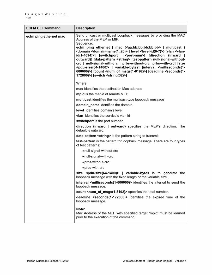
DragonWave Inc. 198
Horizon Quantum Release 1.02.00 Wireless Ethernet Product User Manual – Volume 4
ECFM CLI Command Description
ecfm ping ethernet mac
Send unicast or multicast Loopback messages by providing the MAC Address of the MEP or MIP. Sequence: ecfm ping ethernet [ mac {<aa:bb:bb:bb:bb:bb> | multicast } {domain <domain-name(1..20)> | level <level-id(0-7)>} [vlan <vlan-id(1-4094)>] [switchport <port-num>] [direction {inward | outward}] [data-pattern <string> |test-pattern null-signal-without-crc | null-signal-with-crc | prbs-without-crc |prbs-with-crc] [size <pdu-size(64-1400)> | variable-bytes] [interval <milliseconds(1-600000)>] [count <num_of_msgs(1-8192)>] [deadline <seconds(1-172800)>] [switch <string(32)>] Where mac identifies the destination Mac address mpid is the mepid of remote MEP. multicast identifies the multicast-type loopback message domain_name identifies the domain. level identifies domain’s level vlan identifies the service’s vlan id switchport is the port number. direction {inward | outward} specifies the MEP’s direction. The default is outward. data-pattern <string> is the pattern string to transmit test-pattern is the pattern for loopback message. There are four types of test patterns:
• null-signal-without-crc • null-signal-with-crc • prbs-without-crc • prbs-with-crc
size <pdu-size(64-1400)> | variable-bytes is to generate the loopback message with the fixed length or the variable size. interval <milliseconds(1-600000)> identifies the interval to send the loopback message. count <num_of_msgs(1-8192)> specifies the total number. deadline <seconds(1-172800)> identifies the expired time of the loopback message. Note: Mac Address of the MEP with specified target “mpid” must be learned prior to the execution of the command.
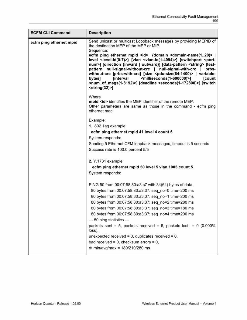
Ethernet Connectivity Fault Management 199
Horizon Quantum Release 1.02.00 Wireless Ethernet Product User Manual – Volume 4
ECFM CLI Command Description
ecfm ping ethernet mpid
Send unicast or multicast Loopback messages by providing MEPID of the destination MEP of the MEP or MIP. Sequence: ecfm ping ethernet mpid <id> {domain <domain-name(1..20)> | level <level-id(0-7)>} [vlan <vlan-id(1-4094)>] [switchport <port-num>] [direction {inward | outward}] [data-pattern <string> |test-pattern null-signal-without-crc | null-signal-with-crc | prbs-without-crc |prbs-with-crc] [size <pdu-size(64-1400)> | variable-bytes] [interval <milliseconds(1-600000)>] [count <num_of_msgs(1-8192)>] [deadline <seconds(1-172800)>] [switch <string(32)>] Where mpid <id> identifies the MEP identifier of the remote MEP. Other parameters are same as those in the command - ecfm ping ethernet mac. Example: 1. 802.1ag example: ecfm ping ethernet mpid 41 level 4 count 5 System responds: Sending 5 Ethernet CFM loopback messages, timeout is 5 seconds Success rate is 100.0 percent 5/5 2. Y.1731 example: ecfm ping ethernet mpid 50 level 5 vlan 1005 count 5 System responds: PING 50 from 00:07:58:80:a3:c7 with 34(64) bytes of data. 80 bytes from 00:07:58:80:a3:37: seq_no=0 time=200 ms 80 bytes from 00:07:58:80:a3:37: seq_no=1 time=200 ms 80 bytes from 00:07:58:80:a3:37: seq_no=2 time=280 ms 80 bytes from 00:07:58:80:a3:37: seq_no=3 time=180 ms 80 bytes from 00:07:58:80:a3:37: seq_no=4 time=200 ms --- 50 ping statistics --- packets sent = 5, packets received = 5, packets lost = 0 (0.000% loss), unexpected received = 0, duplicates received = 0, bad received = 0, checksum errors = 0, rtt min/avg/max = 180/210/280 ms

DragonWave Inc. 200
Horizon Quantum Release 1.02.00 Wireless Ethernet Product User Manual – Volume 4
ECFM CLI Command Description
ecfm traceroute ethernet mac
Initiate Linktrace message by providing the MAC Address of the MEP or MIP. Sequence: ecfm traceroute ethernet mac <aa:aa:aa:aa:aa:aa> {domain <domain-name(1..20)> | level <level-id(0-7)>} [vlan <vlan-id(1-4094)>] [time-to-live <ttl-value(1-255)> press Enter Where mac <aa:aa:aa:aa:aa:aa> identifies the destination Mac address. domain <domain-name(1..20)> identifies the domain name. level <domain-name(1..20)> identifies the domain’s level. vlan <vlan-id(1-4094)> identifies the service’s vlan id. time-to-live <ttl-value(1-255)> identifies TTL value. Note: Mac Address of the MEP with specified target “mpid” must be learned prior to the execution of the command.
ecfm traceroute ethernet mpid
Initiate Linktrace message by providing MEPID of the destination MEP of the MEP or MIP. Sequence: ecfm traceroute ethernet mpid <id> {domain <domain-name(1..20)> | level <level-id(0-7)>} [vlan <vlan-id(1-4094)>] [time-to-live <ttl-value(1-255)> Where mpid <id> identifies the MEP identifier of the remote MEP. Other parameters are same as those in the command - ecfm ping ethernet mac. The system responds: (Example) ->ecfm traceroute ethernet mpid 41 level 4 Traceroute to Macaddress 00:10:94:00:00:11 in domain MD_level_4 at level 4 with vlanId 0 ------------------------------------------------------------------------- Hops Host Ingress MAC Ingress Action Relay Action Next Host Egress MAC Egress Action Fwd Status ------------------------------------------------------------------------- 1 00:01:00:07:58:80:a3:37 - - RlyFDB 00:00:00:10:94:00:00:16 00:10:94:00:00:16 EgrOK Forwarded 2 00:00:00:10:94:00:00:16 - - RlyHit
00:00:00:10:94:00:00:11 00:10:94:00:00:11 EgrOK Terminal MEP

Ethernet Connectivity Fault Management 201
Horizon Quantum Release 1.02.00 Wireless Ethernet Product User Manual – Volume 4
ECFM CLI Command Description
ecfm frame delay Start or Stop the ecfm delay measurement calculations. Sequence: ecfm frame delay [start | stop] type {one-way | two-way } level <level-id(0-7)> [vlan <vlan-id(0-7)>] [switchport <port-num>] [direction {inward | outward}]{mepid <mpid(1-8191)> | mac <aa:aa:aa:aa:aa:aa>} [count<num_of_observations(1-8192)>] [interval <milliseconds(10-10000)>] [deadline <seconds(1-172800)>] [switchname <context_name>]] press Enter Where start | stop is to start ot stop frame delay message type { two-way } identifies the two-way performance measurement level <level-id(0-7)> identifies the domain’s level vlan <vlan-id(0-7)> identifies the service’s vlan id switchport <port-num> identifies the port number direction {inward | outward} specifies the direction of the local MEP. The default is “outward”. mepid <mpid(1-8191)> identifies the identifier of the local MEP mac <aa:aa:aa:aa:aa:aa> identifies the target’s Mac address count <num_of_observations(1-8192)> specifies the total number of frame delay messages. interval <milliseconds(10-10000)> specifies the interval of frame delay message deadline <seconds(1-172800)> identifies the expired time of the frame delay message. Note: Mac Address of the MEP with specified target “mpid” must be learned prior to the execution of the command. Run the command ‘get ecfm frame delay buffer’ to see the result of frame delay measurement, Example: ->ecfm frame delay start type two-way level 7 vlan 1007 mepid 71 count 5 interval 2000 ->get ecfm frame delay buffer Interface : gigabitethernet 0/1 MEP-ID : 222 Level : 2 VLAN-ID : 1002 peer mac-address frame-delay IFDV FDV 00:07:58:00:a3:c7 240.0ms 0.000ms 0.00ms 00:07:58:00:a3:c7 160.0ms 0.000ms 0.00ms --- 00:07:58:00:a3:37 frame delay statistics --- measurement timestamp = 10 Jul 2078 10:50:1, packets sent = 2, packets received = 2, frame delay average = 200.0ms, IFDV average = 0.000ms, FDV average = 0.000ms
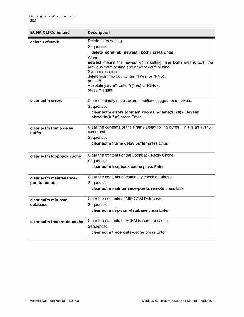
DragonWave Inc. 202
Horizon Quantum Release 1.02.00 Wireless Ethernet Product User Manual – Volume 4
ECFM CLI Command Description
delete ecfmmib Delete ecfm setting. Sequence:
delete ecfmmib [newest | both] press Enter Where newest means the newest ecfm setting; and both means both the previous ecfm setting and newest ecfm setting. System response: delete ecfmmib both Enter Y(Yes) or N(No) : press Y Absolutely sure? Enter Y(Yes) or N(No) : press Y again
clear ecfm errors Clear continuity check error conditions logged on a device.. Sequence:
clear ecfm errors [domain <domain-name(1..20)> | levelid <level-id(0-7)>] press Enter
clear ecfm frame delay buffer
Clear the contents of the Frame Delay rolling buffer. This is an Y.1731 command. Sequence:
clear ecfm frame delay buffer press Enter
clear ecfm loopback cache Clear the contents of the Loopback Reply Cache. Sequence:
clear ecfm loopback cache press Enter
clear ecfm maintenance-ponits remote
Clear the contents of continuity check database. Sequence:
clear ecfm maintenance-ponits remote press Enter
clear ecfm mip-ccm-database
Clear the contents of MIP CCM Database. Sequence:
clear ecfm mip-ccm-database press Enter
clear ecfm traceroute-cache Clear the contents of ECFM traceroute cache. Sequence:
clear ecfm traceroute-cache press Enter

Ethernet Connectivity Fault Management 203
Horizon Quantum Release 1.02.00 Wireless Ethernet Product User Manual – Volume 4
This page left blank intentionally

Horizon Quantum Release 1.02.00 Wireless Ethernet Product User Manual – Volume 4
Copyright © 2000-2012 DragonWave Inc. Printed in Canada. All rights reserved. Quantum™ Product Manual, 83-000093-01-01-01 Visit us on the Internet at: http://www.dragonwaveinc.com/