Embed Size (px)
Citation preview

Connected Plant
HONEYWELL TRACETM
R 121
___________________________________
USER GUIDE
___________________________________
HTDOC-X436-en-121A
December 2017

2
DISCLAIMER
This document contains Honeywell proprietary information. Information contained herein
is to be used solely for the purpose submitted, and no part of this document or its contents
shall be reproduced, published, or disclosed to a third party without the express
permission of Honeywell International Sàrl.
While this information is presented in good faith and believed to be accurate, Honeywell
disclaims the implied warranties of merchantability and fitness for a purpose and makes
no express warranties except as may be stated in its written agreement with and for its
customer.
In no event is Honeywell liable to anyone for any direct, special, or consequential damages.
The information and specifications in this document are subject to change without notice.
Copyright 2018- Honeywell International Sàrl

HTDOC-X436-en-121A 3
Table of contents 1 ABOUT THIS DOCUMENT .............................................................................................................................. 7
1.1 Revision history ....................................................................................................................................................... 7
1.2 Introduction ............................................................................................................................................................... 7
1.3 What’s new in Honeywell Trace R121? ........................................................................................................ 7 1.3.1 Offline Mode ....................................................................................................................................................... 10
1.4 Architecture ............................................................................................................................................................ 11
1.5 Supported Topologies ....................................................................................................................................... 14
1.6 Key features ............................................................................................................................................................ 14
2 DASHBOARD .................................................................................................................................................. 15
2.1 View changes, engineering anomalies, trendlines ............................................................................. 15
2.2 Configure trend lines ......................................................................................................................................... 18
3 GLOBAL SEARCH ......................................................................................................................................... 20
3.1 Search tags ............................................................................................................................................................. 20
4 TAG REFERENCES ....................................................................................................................................... 22
4.1 Search tags ............................................................................................................................................................. 22 4.1.1 Useful tips to search tags ............................................................................................................................ 23
4.2 Graphical view ....................................................................................................................................................... 23
4.3 Tabular view ............................................................................................................................................................ 23 4.3.1 Properties ............................................................................................................................................................. 24 4.3.2 Pin ............................................................................................................................................................................ 25 4.3.3 Expand/Collapse .............................................................................................................................................. 26 4.3.4 Display options .................................................................................................................................................. 28 4.3.5 Connections ........................................................................................................................................................ 30 4.3.6 View connected tags ....................................................................................................................................... 30 4.3.7 Download tag details ...................................................................................................................................... 33 4.3.8 Print tag details ................................................................................................................................................. 33
4.4 View Tag References .......................................................................................................................................... 33
5 LOGICAL VIEW .............................................................................................................................................. 35
5.1 Introduction ............................................................................................................................................................ 35
5.2 Navigating the Logical View Hierarchy .................................................................................................... 36
5.3 Search........................................................................................................................................................................ 37
5.4 Filter............................................................................................................................................................................ 37
5.5 Change and anomaly count ........................................................................................................................... 39
5.6 View asset information ..................................................................................................................................... 39

HTDOC-X436-en-121A 4
6 HARDWARE VIEW ......................................................................................................................................... 45
6.1 Search........................................................................................................................................................................ 45
6.2 Traversing the Hardware hierarchy ............................................................................................................ 46 6.2.1 View Properties .................................................................................................................................................. 46
6.3 Display options ..................................................................................................................................................... 48
6.4 View Hardware Information ............................................................................................................................ 48
7 NETWORK VIEW ........................................................................................................................................... 52
7.1 Prerequisite ............................................................................................................................................................ 52
7.2 Search........................................................................................................................................................................ 53
7.3 Traversing the network hierarchy ................................................................................................................ 53 7.3.1 View Properties .................................................................................................................................................. 54 7.3.2 Display options .................................................................................................................................................. 54
7.4 View asset information ..................................................................................................................................... 55
8 LICENSE .......................................................................................................................................................... 58
9 CHANGE DETECTION ................................................................................................................................. 59
9.1 Changes ................................................................................................................................................................... 60 9.1.1 Aggregate and iterative change ................................................................................................................ 60 9.1.2 Migration .............................................................................................................................................................. 61 9.1.3 Rules for displaying changes ..................................................................................................................... 61
9.2 Filter changes ........................................................................................................................................................ 62 9.2.1 Save Filter ............................................................................................................................................................. 64 9.2.2 Quick Filter .......................................................................................................................................................... 64 9.2.3 Export changes ................................................................................................................................................. 64 9.2.4 Print changes ..................................................................................................................................................... 64 9.2.5 Filter and view changes................................................................................................................................. 64
9.3 Display Logical view ........................................................................................................................................... 65
9.4 Act on Changes .................................................................................................................................................... 65
9.5 Suppression ........................................................................................................................................................... 68 9.5.1 Rules governing suppression .................................................................................................................... 68 9.5.2 Suppress changes ........................................................................................................................................... 71 9.5.3 Manage Suppression List ............................................................................................................................ 73
10 CHANGE REQUESTS ................................................................................................................................... 75
10.1 Create Work Order ............................................................................................................................................... 75
10.2 View list of Work Orders .................................................................................................................................... 77
10.3 Work on states assigned to you in a work order ................................................................................... 78
11 ENGINEERING ANOMALY ......................................................................................................................... 80

HTDOC-X436-en-121A 5
11.1 Filter engineering anomalies ......................................................................................................................... 81 11.1.1 Save Filter ............................................................................................................................................................. 83 11.1.2 Quick Filter .......................................................................................................................................................... 83 11.1.3 Export engineering anomalies .................................................................................................................. 83 11.1.4 Print engineering anomalies ...................................................................................................................... 84
11.2 Filter and view engineering anomalies ..................................................................................................... 84
11.3 Act on engineering anomalies ...................................................................................................................... 86
11.4 Custom Engineering Anomalies .................................................................................................................. 87 11.4.1 Create a custom anomaly ............................................................................................................................ 87 11.4.2 Tag Name Convention ................................................................................................................................... 88 11.4.3 Switch Model (Applicable to Experion & ESVT systems only) ................................................... 89 11.4.4 Switch IOS Version (Applicable to Experion & ESVT systems only) ........................................ 90 11.4.5 Anomaly Settings ............................................................................................................................................. 91
12 SPARES ............................................................................................................................................................ 93
12.1 Filter spares ............................................................................................................................................................ 93 12.1.1 Save Filter ............................................................................................................................................................. 94 12.1.2 Quick Filter .......................................................................................................................................................... 94 12.1.3 Export spare list ................................................................................................................................................ 95 12.1.4 Print list of spares ............................................................................................................................................ 95
12.2 Filter and view spares ........................................................................................................................................ 95
12.3 Actions ...................................................................................................................................................................... 96 12.3.1 Create Project .................................................................................................................................................... 96 12.3.2 Delete Project ..................................................................................................................................................... 97 12.3.3 Act on spares ...................................................................................................................................................... 97
13 QUERY ............................................................................................................................................................. 98
13.1 Run queries ............................................................................................................................................................. 98
13.2 Defining a query ................................................................................................................................................ 100
13.3 Guidelines for defining a query ................................................................................................................. 101 13.3.1 Guidelines for defining condition expression in a query........................................................... 102 13.3.2 Representing parameter data types in condition expression ................................................. 103 13.3.3 Errors ................................................................................................................................................................... 103
14 REPORTS ...................................................................................................................................................... 105
14.1 Create Report Package .................................................................................................................................. 107
14.2 Generate and view reports ........................................................................................................................... 112
15 PERMISSIONS ............................................................................................................................................ 115
15.1 Edit Permissions ............................................................................................................................................... 115
16 APPENDIX .................................................................................................................................................... 117

HTDOC-X436-en-121A 6
16.1 How to print large diagrams from PDF .................................................................................................. 117
17 TROUBLESHOOTING ................................................................................................................................ 119
17.1 Data collection failure .................................................................................................................................... 119
18 NOTICES....................................................................................................................................................... 122

HTDOC-X436-en-121A 7
1 About this document
This document provides instructions to use the Honeywell Trace Server web application.
1.1 Revision history
Version Release Date Description
A R 121 December 2017 Initial release of the document for R121.
1.2 Introduction Knowledge retention and management are key challenges faced by most industries today.
A critical requirement of any control system is information about how various components
interconnect, the direction of signal/data flow, and their inter-dependencies. When this is
documented well, troubleshooting issues is quick and easy. However, as is often the case,
if the documentation is not updated regularly, troubleshooting problems becomes difficult
and time consuming, directly impacting issue resolution time. Also, a lack of up-to-date
documentation increases dependency on individuals with the added risk of losing this
knowledge base when people retire or move on.
It is extremely important that information about every control element's usage throughout
the control system is clearly understood and documented so that, in case control system
element goes for maintenance or modification, it becomes easier to ensure that process
outage does not occur.
Honeywell Trace®is a solution designed for documentation and change management of
intellectual property and system assets of Honeywell customers. Systems include both
Honeywell and third-party DCS systems.
Documenting changes occurring in a system is necessary for tracking, validation, audit
verifications, and to aid in troubleshooting. Trace is a powerful change and anomaly
management system that helps you view, track, search, sort, and act upon changes
occurring on the control system. With integration of multiple control systems such as
Experion, PHD, TPS, Triconex, Safety Manager, OSIPI, FSC, and SPI, Trace provides a
singular means to track changes across disparate systems. Standardization of the process
for change request and anomalies management and tracking them effectively becomes
easy with the creation of work order with pre-defined templates that ensure a multi-state
process involving multiple users is enforced where assigned users approve each state
based on verification of check list of items.
Identifying anomalies to codified rules for control elements becomes a simple task as
system- and custom- defined rules are used to evaluate and identify when such

ABOUT THIS DOCUMENT
HTDOC-X436-en-121A 8
engineering anomalies exist. More effective utilization of hardware resources is made
possible by providing means to create an inventory of used and spare IOs, which can be
marked as assigned to projects or marked as free for use.
Knowledge retention and management of your control system is further aided with ability
to view hardware resources contained within it, pictorially. The Hardware feature provides
functional grouping and hierarchical view of these hardware assets. Similar hardware
assets form as asset group. Within an asset are grouped child hardware elements and so
on. You can select an asset group to view all assets grouped within it. You can then select a
hardware asset and view the child hardware assets contained in it. Example: In an Experion
system, the Controllers asset group contains C300s, C200s, ACE, and OPC. A C300/C200
will contain IOLINK modules that are connected to it. For each hardware asset or asset
group, clicking the UI control provides detailed asset information in a tabbed structure.
Currently, the Hardware view is available for Experion, TPS, Safety Manager, Triconex, and
Fail Safe Controller (FSC) systems only.
With the Network View, you can view the hierarchy of network elements within the Experion
system beginning with an L2 Top level switch downwards. You can drill down the hierarchy
of network elements traversing the network of connected sub elements such as other L2
switches, CF9s, Controllers, FTE Gateways, Servers, Stations, SCE, and ACE. Currently,
Network View is supported for Experion systems only.
The Change Request or Work Order feature enables you to track and assign change
requests or anomalies to users. By providing a template that has a pre-defined number of
states and a checklist of items to be verified in each state, a work order helps in ensuring
any change or anomaly passes through the watchful eyes of the assigned users whose
approval is required to proceed to the succeeding stage until the work order is completed.
The tedious job of writing SQL queries to zero-in on engineering anomalies is a thing of
the past as Trace simplifies the task by providing UI controls to create and execute even
the most complex anomaly search queries.
Ability to view hardware and network assets within your control system – pictorially - is very
handy for quickly navigating to a required hardware or network component. The
components are functionally grouped and a hierarchical view is presented so you can
quickly locate the component you are looking for and view additional information.
Change Requests or Anomalies feature enables you to track and assign change requests
or anomalies to users. By providing a template that has a pre-defined number of states
and a checklist of items to be verified in each state, a work order helps in ensuring any
change or anomaly passes through the watchful eyes of the assigned users whose
approval is required to proceed to the succeeding stage until the work order is completed.

ABOUT THIS DOCUMENT
HTDOC-X436-en-121A 9
Generating reports of changes, engineering anomalies, queries in print and electronic
forms and scheduling reports is a breeze.
1.3 What’s new in Honeywell Trace R121? The following new features or feature enhancements have been made in R121:
• Offline Mode – You can collect data from plant systems (using laptop/any
workstation node present in plant at the L3/L2 network level) using the Offline Data
Collector and import or upload the collected data in the Trace Server located at the
centralized engineering office or at a Honeywell project office (Offline Trace Server).
• Hardware view for Safety Manager and Triconex has been introduced.
• Searching for tags in Hardware and Network views. Helps save time and effort by
helping you zero-in on a particular node quickly through the wild card character
supported search mechanism. The selected node from the search results displays
the hardware view.
• View a list of external references for a controller. Useful when undertaking any
maintenance, troubleshooting, migration of controller to know all the external
references (incoming and outgoing), which can help you in informed decision
making and taking preventive actions.
• View a list of external references for a system. Useful when you want to know all the
incoming and outgoing external references for a system by generating a report,
which can help you make informed decisions and take preventive actions to avoid
any collateral damages in situations such as taking down a system. Examples:
One Experion cluster to another Experion cluster through OPC Integrator
One Experion cluster to another Experion cluster through ECI: Server Responder
One Experion cluster to Safety Manager through ECI: CDA
• Enhancements to Hardware View for a TPS system have been made to provide
additional information:
Missing Reference: CL Block Tag (TPS)
Missing Reference: CL Sequence Tag (TPS)
Invalid point.parameter in Native Window display and group/trend
Detailed HPM slot configuration in Hardware view
UCN numbers in Hardware view
Numeric and Flags used in logic block appear in Logic View diagram with their
value
• PHD shadow server support for reference connections.
• Listing of TPS Hardware and software inventory in the System Performance Report.

ABOUT THIS DOCUMENT
HTDOC-X436-en-121A 10
• Additional enhancements:
FSC IO channel Spare management
SM release support (up-to 15X.X release)
EHPM and ENIM support
1.3.1 Offline Mode Beginning with R121, Honeywell has introduced the Honeywell Offline Trace Server and
Offline Data Collector to enable data collection even when the Trace Server component
does not have network connectivity with remote nodes. This is termed as the Offline Mode.
In the Offline Mode of working, the Offline Data Collector is installed at remote sites on a
computer that has network connectivity to remote nodes that have control system data.
The Offline Data Collector collects control system data and creates a package that is
password protected. The person collecting the data then manually copies this package to
a portable drive or a network share.
The package is manually brought and copied to the Offline Trace Server, which resembles
the Honeywell Trace Server in all respects except that it cannot perform data collection.
Instead, the package created by the Offline Data Collector is uploaded to create the
snapshot data.

ABOUT THIS DOCUMENT
HTDOC-X436-en-121A 11
1.4 Architecture The following diagrams illustrate the architecture of Honeywell Trace.
Connected Mode - Honeywell Trace Installed at L3 and L3.5
L2 DOMAIN CONTROLLER TRICONEX
L2 SWITCH GREEN
L3 SWITCH
L3.5 DOMAIN CONTROLLER PHD DATABASE SERVER / SHADOW SERVER
L3.5 SWITCH (DMZ)
L2 SWITCH YELLOW
FSC SPI
BUSINESS NETWORK L3.5 TRACE SERVER(OPTIONAL)
L4 DOMAIN CONTROLLER
INTERNET / INTRANET
SAFETY MANAGER
LEVEL 4 NETWORK
LEVEL 3.5 NETWORK (DMZ)
LEVEL 3 NETWORK
LEVEL 2 NETWORK
ROUTER
FIREWALL
L3 DOMAIN CONTROLLER OSIPI PROCESS NETWORK L3 TRACE SERVERL3 TRACE CLIENT
ESV (A/B)
EXPERION CLUSTER
ES-C
PHD COLLECTOR
ESV-T (A/B)
INTEGRATED EXPERION CLUSTER
ES-T
BUSINESS NETWORK L4 TRACE CLIENT
L3.5 TRACE CLIENT

ABOUT THIS DOCUMENT
HTDOC-X436-en-121A 12
Connected Mode - Honeywell Trace Installed at L3 and L4 With Relay Server
L2 DOMAIN CONTROLLER TRICONEX
L2 SWITCH GREEN
L3 SWITCH
L3.5 DOMAIN CONTROLLER PHD DATABASE SERVER / SHADOW SERVER
L3.5 SWITCH (DMZ)
L2 SWITCH YELLOW
FSC SPI
L4 DOMAIN CONTROLLER
INTERNET / INTRANET
SAFETY MANAGER
LEVEL 4 NETWORK
LEVEL 3.5 NETWORK (DMZ)
LEVEL 3 NETWORK
LEVEL 2 NETWORK
ROUTER
FIREWALL
L3 DOMAIN CONTROLLER OSIPI PROCESS NETWORK L3 TRACE SERVERL3 TRACE CLIENT PHD COLLECTOR
ESV (A/B)
EXPERION CLUSTER
ES-C ESV-T (A/B)
INTEGRATED EXPERION CLUSTER
ES-T
BUSINESS NETWORK L4 TRACE CLIENT
L3.5 TRACE CLIENT
BUSINESS NETWORK L4 TRACE SERVER
RELAY SERVER (PROXY+)

ABOUT THIS DOCUMENT
HTDOC-X436-en-121A 13
Honeywell Trace Architecture – Offline Mode
L2 DOMAIN CONTROLLER TRICONEX
L2 SWITCH GREEN
PHD COLLECTOR
L2 SWITCH YELLOW
FSC SPISAFETY MANAGER
LEVEL 2 NETWORK
CENTRAL OFFICE WITH OFFLINE TRACE SERVER
L3 DOMAIN CONTROLLER OSIPI
L3 SWITCH
OFFLINE DATA COLLECTOR *
LEVEL 3 NETWORK
DATA COLLECTION IS DONE & PACKAGE FILE IS COPPIED TO A LAPTOP / PORTBALE DRIVE
ROUTER
REMOTE SITE WITH OFFLINE DATA COLLECTOR
OFFLINE TRACE SERVER
TRACE CLIENT
DOMAIN CONTROLLER
LEVEL 3 NETWORK
PACKAGE FILE IS COPIED FROM LAPTOP / PORTBALE DRIVE
PACKAGE FILE IS PHYSICALLY TRANSPORTED FROM SITE TO CENTRAL OFFICE
OFFLINE DATA COLLECTOR *
ESV (A/B)
EXPERION CLUSTER
ES-C ESV-T (A/B)
INTEGRATED EXPERION CLUSTER
ES-T
* OFFLINE DATA COLLECTOR CAN BE AT LEVEL 2 OR LEVEL 3
FOR L3-L3.5 AND L3-L4 CONNECTIONS, SEE CONNECTED MODE

ABOUT THIS DOCUMENT
HTDOC-X436-en-121A 14
1.5 Supported Topologies Honeywell Trace installation is supported in both Domain and Workgroup topologies.
1.6 Key features Explore
• Dashboard that aggregates data from all configured systems and presents the
number of changes and engineering anomalies
• Tag references and tag search across systems
• Logical view of systems and assets
• Hardware view of systems
• Network view of systems
• Feature based licensing
Manage
• Change tracking and change analysis
• Change requests management
• Engineering anomaly management
• Spares management
• Query control modules and parameters
• Generate reports of changes, engineering anomalies, queries, and System
performance reports
Configure
In the current release, Trace supports:
• Honeywell DCS systems: TPS, Experion PKS, and Experion Integrated TPS
• Honeywell Safety systems (Safety Manager)
• Uniformance Process Historian Database (PHD)
• Fail Safe Controller (FSC)
• Smart Plant Instrumentation (SPI)
• OSIsoft PI
• Triconex

HTDOC-X436-en-121A 15
2 Dashboard
Honeywell Trace’s Dashboard is an intuitive display of change and anomaly data of your
overall control and instrumentation (C&I) system. Donut charts, stacked bar charts and
trend lines for changes and engineering anomalies, site-wise or for a single control system,
provide a bird’s-eye view of the system. Data collected from the latest snapshot is
compared with all previous snapshots to display engineering anomalies and changes.
2.1 View changes, engineering anomalies, trendlines The Changes pane displays donut charts and a stacked horizontal bar graph. You can
select a system or the overall site to view donut charts along with the count of changes
needing attention. The stacked horizontal bar graph view provides change count for all
systems. For a selected system, click the charts and bar graphs to display the
corresponding change data on the Change Detection page.

DASHBOARD
HTDOC-X436-en-121A 16
Similarly, the Engineering Anomaly pane displays count of engineering anomalies
needing attention for a selected system or overall site in donut charts. Also, the system-
wise anomaly count is displayed as a stacked horizontal bar graph. For a selected system,
click the charts and bar graphs to display the corresponding anomaly data on the
Engineering Anomaly page.

DASHBOARD
HTDOC-X436-en-121A 17
Trend lines for changes and engineering anomalies are also available as line graphs for
the top 5 systems (count-wise) for a period of one year ranging from the current date. For
example, if today’s date is Oct 30, 2015, trend line data from all snapshots collected from
Oct 30, 2014 - Oct 30, 2015 will be the default display.
Intuitive control has been provided to select trend line time period. Hover your mouse over
the 3D area chart at the bottom of the trend line and when the cursor changes to a +
symbol, drag and select a time period to view trend line data for the selected period.

DASHBOARD
HTDOC-X436-en-121A 18
2.2 Configure trend lines Click the respective settings button of the Change or Engineering Anomaly pane to
configure the systems, changes or anomalies, and time period for which you want to view
trend line data on the dashboard.
Options to select snapshots, change/anomaly type, and change/anomaly status are
provided. Make your selections and click Update. Trend line data is displayed based on
your selection. Click the minimize button to return to the dashboard. Trend lines for the top
5 systems (count-wise) will be displayed on the dashboard.
ATTENTION
On first time access after installation, the dashboard appears blank because a snapshot is needed for data to be displayed. After the first snapshot is collected, only engineering anomalies data is displayed. A minimum of two snapshots must be collected to display change data.

DASHBOARD
HTDOC-X436-en-121A 19

GLOBAL SEARCH
HTDOC-X436-en-121A 20
3 Global Search
Trace provides a powerful tool to search tags across all configured systems based on a
selected snapshot. The results of the search are listed in a tabular format providing
information about the tag’s Type and the System it belongs to. Additionally, links to the
tag’s Tag Reference view, Logical View, and Network View are provided.
The global search tool is located on the top right corner of the screen and can be accessed
no matter which screen you are in currently.
3.1 Search tags To search tags:
1. On the Trace web application screen, click the Global Search icon to display the Tag Locator window.
2. Select the Snapshot. The latest snapshot is the default selection.
3. To search for a tag reference, enter your search string and use the wildcard
characters * or ? as applicable and press Enter or click the icon. The results of the
search are displayed in a tabular format.
4. Click the required link under Tag Reference, Logical View, or Network View to
display the respective view for the selected tag.

GLOBAL SEARCH
HTDOC-X436-en-121A 21
5. Click the close button to close the Tag Locator window.
Useful tips to search tags Trace supports wild card character search with * and ? for searching tags and function
blocks.
Examples
* lists all control modules
*. * lists all function blocks
CM* lists all tags beginning with the name CM (CM_A1).
CM*.* lists function blocks beginning with the name CM (CM_1.PIDA).

TAG REFERENCES
HTDOC-X436-en-121A 22
4 Tag References
In any given C&I system, the number of tags (control elements: assets, control modules,
function blocks) is in the order of thousands or multiples of thousands. Typically, but not
limited to reasons of maintenance and troubleshooting an instrument or control module, it
is critical to have oversight of all its references and take preventive actions for all
downstream connections to ensure zero impact on the running process.
Without a powerful search functionality, locating a control element will be analogous to
looking for a needle in a haystack. Any search mechanism would retrieve a tag and its
details. But is that enough? Would it not be useful to view the selected tag and see its
internal and external connections to understand how data flows? View its properties and
its associations? Wouldn’t it be desirable to move from one tag to its connected tags and
view their properties and associations too? Will it be helpful if along with a graphical
format, a tabular view of a tag and its connections is available too? Isn’t it valuable if you
could select a tag and view its place in the logical hierarchy within an asset (its logical
view)? How about being able to download a tag’s information or print it out on paper?
Trace offers all this and more with a simple yet powerful tag search functionality. Based on
a selected snapshot, the search feature supports wildcard characters * and ?. After you
search for and select a tag of interest, its connections with other tags and its properties are
displayed in graphical and tabular formats. You can also navigate to connected tags and
view their properties, and connections making understanding dataflow seamless. Printing
and downloading tag information is also possible at the click of a button.
4.1 Search tags Trace provides a simple method to search tags and view all its details thus avoiding
problems during maintenance.
To search tags:
1. On the Trace Dashboard, click and select Tag References.
2. Select the Snapshot and System from the respective drop-down lists on the top left
corner of the page. The latest snapshot is the default selection.
3. To search for a tag reference, enter your search string and use the wildcard
characters * or ? as applicable and press Enter or click the icon. The results of the
search are displayed on the left pane. Click the item you are interested in to display
the graphical view on the right pane. (The first item in the results will be displayed by
default).

TAG REFERENCES
HTDOC-X436-en-121A 23
4. By default, the selected tag and its connected (upstream and downstream) tags and
their connections are displayed in a graphical format.
4.1.1 Useful tips to search tags Trace supports wild card character search with * and ? for searching tags and function
blocks.
Examples
Search String Result
* lists all logical tags
*. * lists all function blocks
CM* lists all tags beginning with the name CM (CM_A1).
CM*.* lists function blocks beginning with the name CM (CM_1.PIDA).
Aicm?dsa Lists Aicm1DSA, Aicm2DSA, and so on.
4.2 Graphical view In the graphical view, for a selected tag (current tag), its external connections with
upstream and downstream tags are displayed. While the selected tag (current tag) is
displayed in orange color, the connected (upstream or downstream) tags are displayed in
blue.
The system name where the upstream and downstream tags are configured are also
displayed.
Each connection between the current (orange) and upstream or downstream (blue) tags is
displayed by an arrow indicating the direction of data flow and a number that signifies the
number of connections.
4.3 Tabular view Displays the current tag’s connections in a tabular format at the bottom of the screen.

TAG REFERENCES
HTDOC-X436-en-121A 24
4.3.1 Properties Displays the Properties window that lists all the parameters of the selected control module,
function block, or connection.

TAG REFERENCES
HTDOC-X436-en-121A 25
4.3.2 Pin Pins the current tag to the screen. Even if you moved by clicking an upstream or
downstream tag, the pinned tag will remain in view. You can pin a maximum of 20 tags.

TAG REFERENCES
HTDOC-X436-en-121A 26
All pins are listed in a pinned items list on the top-right corner. To unpin a tag or function
block, click the tag/function block and click the Pin button again or click the
corresponding delete button in the pinned items list.
The pinned items are removed if you perform a new search for tags or select a different tag
from the list of tags on the left pane.
4.3.3 Expand/Collapse Expand button displays all the function blocks and their connections within the selected
tag. The Collapse button hides the function blocks and reverts back to displaying the tag
with its external connections.

TAG REFERENCES
HTDOC-X436-en-121A 27
The Inner connections check-box on the lower left of the screen can be used to display the
internal connections within a selected tag.

TAG REFERENCES
HTDOC-X436-en-121A 28
4.3.4 Display options You have 4 display options to control the graphical representation of tags on your screen.
You can quickly see an overview, focus on a selected area of the graphic or zoom in or out
of a graphic.
• Overview – Click this to get a fully zoomed out overall view (overview) of the tags you
are viewing in a small window. In the Overview window, as you move the selective
focus tool (blue rectangle), the tags/connections within the focus area will be seen
on the screen. You can use the black dot handle to increase/decrease the focus
area. Click the Eye icon again to close the Overview window.

TAG REFERENCES
HTDOC-X436-en-121A 29
• Fit to screen – This fits all the tags and their connections within the screen.
• Zoom in – Click to zoom in.
• Zoom out – Click to zoom out.

TAG REFERENCES
HTDOC-X436-en-121A 30
4.3.5 Connections Connections indicate the direction and type of data flow within or between tags. Each
connection between tags is shown by an arrow indicating the direction of data flow and a
number that signifies the number of connections.
When you expand a tag, connections show labels at the leading and trailing edge of the
arrow displaying the indicating the data read at the source and the data delivered to the
destination.
• Inner connections: These are connections internal to the selected tag. Use the
checkbox to view/hide inner connections.
• SCM/RCM connections: For SCM/RCM/ Master Recipe connections, there are
options to view Main handler or the multiple subroutines.
• Array connections: These are connections in case an Array block is used in the logic.
• External references: For external references, connection type attributes are
indicated.
4.3.6 View connected tags While you are viewing the current tag and its connections/properties, you can also click
the upstream or downstream tag, in which case that tag becomes the current tag, and view
its upstream and downstream connections. In this manner, you can hop to adjacent tags
helping you to understand the data trail easily and seamlessly.

TAG REFERENCES
HTDOC-X436-en-121A 31
Tabular view
In the tabular format, connections displayed include:
• Logical external connections (upstream and downstream tags)
• Logical Inner connections

TAG REFERENCES
HTDOC-X436-en-121A 32
• Reference connections (tags used in history, display, trend/group configuration,
and so on)
• Alias References
Logical External connections: These are connections of the selected tag with external
control modules, function blocks and so on, i.e., the connections between the current tag
and other tags. The table consists of the following information.
• Current tag: The name of the tag you have chosen to view.
• Container: This is where the current tag is being executed.
• System: System to which the upstream or downstream function block belongs.
• Stream: Represents data flow between tags. A left arrow indicates information flows
from the tag to its connected upstream function block.
• Reference Tag: The tag with which the current tag is communicating.
• Container: This is where the current tag is being executed.
• System: System to which the upstream or downstream function block belongs.
• Connection Type: Available only for logical external connections. Indicates
connection type: For example: PCDI and PCI when the external connection is to SM.
Logical Inner connections: These are connections within the current tag.
• Current tag: The name of the tag you have chosen to view.
• Container: This is where the current tag is being executed.
• System: System to which the upstream or downstream function block belongs.
• Stream: Represents data flow between tags. A left arrow indicates information flows
from the tag to its connected upstream function block.
• Reference Tag: The tag with which the current tag is communicating.
Reference Connections: These are connections involving displays. trends, history, groups,
and PHD.
• Current tag: The name of the tag you have chosen to view.
• Container: This is where the current tag is being executed.
• System: System to which the upstream or downstream function block belongs.
• Reference To
• Object Name
• System

TAG REFERENCES
HTDOC-X436-en-121A 33
• Reference Type
Alias References: These are available only for alias references involving SCMs, RCMs, or
UCMs.
• Current Tag
• Container
• System
• Reference Type
• Additional Info
• Reference Tag
• Container
• System
4.3.7 Download tag details You can download the current tag along with its upstream and downstream connections in
tabular format to a CSV file.
4.3.8 Print tag details You can print the current tag along with its connections in graphical, tabular, or both
formats to paper, XPS, or PDF formats. To print to XPS or PDF formats, your printer must
be configured appropriately. See the How to print large diagram from PDF section for print
settings required for printing large diagrams.
ATTENTION
When you click the Print button, the print preview is displayed in a new page. You must close the print preview (new page) before using the tag Reference Search page again.
4.4 View Tag References Information about a tag and its connections are displayed in both graphical and tabular
formats.
To view a tag reference:
1. On the Trace Dashboard, click and select Tag References.
2. Select the Snapshot and System from the respective drop-down lists on the top left
corner of the page.

TAG REFERENCES
HTDOC-X436-en-121A 34
3. To search for a tag reference, enter your search string and use the wildcard
characters * or ? as applicable and press Enter or click the icon. The results of the
search are displayed on the left pane. Click a tag to view its connections.
4. By default, the selected tag and its upstream and downstream tags and their
connections are displayed in a graphical format.
5. To view the details of a tag, click the tag to display a pop-up tool bar consisting of 4
tools.
6. Check the Inner connections check box to also display the internal connections
within the current tag.
7. Click a function block within the current tag to view its parameters. The Properties
pane appears showing all parameters for the selected function block in alphabetical
order.
8. The tabular view of the current tag displays all logical external connections, logical
inner connections, reference connections, and alias references. It also displays
frequently used properties.
9. You can select adjacent tags and view their function blocks and connections to
understand data flow between tags.
10. To export the list of connections, click , type the file name, and click OK to generate
a csv file.
11. To print the list of changes, click , select graphical view, tabular view, or both, and
click Print. Specify appropriate print settings along with options to print headers and
footers and background graphics.
ATTENTION
The following FSC IO tag properties are not supported in Honeywell Trace R121: Relative address, Max. discrepancy time, Maximum on-time, Trm. Alarm setp. Low, Trm. Alarm setp. High, SER set point low, SER set point high, Max. discrepancy value, Alarm link tag number, Blank code, Sample time Low, Power-on mode, Proportional band, Reset factor, Rate time, PID analog input deviation limit, PID analog output low clamp, PID analog output high clamp, PID set point low clamp, PID set point high clamp and Engineering units for variable type BO.

LOGICAL VIEW
HTDOC-X436-en-121A 35
5 Logical View
A plant is usually divided into multiple areas. Each area is further divided into units and
these units contain control loops. This is the logical hierarchy that Trace depicts in the
logical view.
Use the Logical View to drill-down hierarchically within a system to view critical
information of its constituent control elements. For example, you select an asset to view its
details. From this asset, select any container module that constitutes this asset and view
its details. You can drill down further and view information about function blocks that
constitute this container module.
This feature is designed to provide connections and critical details for the control elements
you select within a system. Apart from graphically viewing connections for a selected tag,
you can view changes that have occurred to the tag over all collected snapshots. You can
also view the properties of a selected tag. Also possible is viewing engineering anomalies
of a selected tag and notes provided by personnel analyzing or resolving the anomaly.
From the top most level – Asset (in an Experion system) or Plant (in a Safety Manager
system) - you can drill down to the smallest component, typically a tag or a function block.
At each hierarchical level, the change and anomaly count information for each component
is displayed. Essentially, with the logical view, you can see the changes and engineering
anomalies that have occurred to a logical group of components over all collected
snapshots.
5.1 Introduction A plant is usually divided into multiple areas. Each area is further divided into units and
these units contain control loops. This is the logical hierarchy that Trace depicts in the
logical view.
Use the Logical View to drill-down hierarchically within a system to view critical
information of its constituent control elements. For example, you select an asset to view its
details. From this asset, select any container module that constitutes this asset and view
its details. You can drill down further and view information about function blocks that
constitute this container module.
This feature is designed to provide connections and critical details for the control elements
you select within a system. Apart from graphically viewing connections for a selected tag,
you can view changes that have occurred to the tag over all collected snapshots. You can
also view the properties of a selected tag. Also possible is viewing engineering anomalies
of a selected tag and notes provided by personnel analyzing or resolving the anomaly.

LOGICAL VIEW
HTDOC-X436-en-121A 36
From the top most level – Asset (in an Experion system) or Plant (in a Safety Manager
system) - you can drill down to the smallest component, typically a tag or a function block.
At each hierarchical level, the change and anomaly count information for each component
is displayed. Essentially, with the logical view, you can see the changes and engineering
anomalies that have occurred to a logical group of components over all collected
snapshots.
5.2 Navigating the Logical View Hierarchy
The terminologies used to describe the hierarchy differ based on the system you choose.

LOGICAL VIEW
HTDOC-X436-en-121A 37
System Top level element Middle level element
Lower level element
Experion Asset Container Control
Module
Control Module
(Tag)
Safety Manager Plant Controller FLD
Triconex Project Programs or Tags
TPS Area Unit Points
OSISoft PI NA
Irrespective of the system you select, Trace recognizes and displays the number of
changes and engineering anomalies for each element at all hierarchical levels. For all
elements, you can also view the properties, logical view of components with connections,
and modifications. The modifications are based on comparison of the current snapshot
with all existing snapshots.
The number of changes and engineering anomalies displayed on a parent element = No. of
changes & engineering anomalies in the parent element + no. of changes and engineering
anomalies of all its child elements.
Click Export button to export the tabular data as a .CSV file.
Click the Print button to launch a preview of the tabular data as a PDF in a separate
window. Choose print options to print the information.
ATTENTION
You must close the print preview (new window) before using the Logical View page again.
5.3 Search Wildcard character search with * and ? is provided to easily search for a control element
you are looking for. In the search box, enter your search string and use the wildcard
characters to search for assets, child assets, or tags at the respective levels.
5.4 Filter Filtering for assets or tags is another way to search for the control element you are looking
for. Shown here is an example of navigating to a tag in Experion, and Safety Manager
systems. Notice that items within filters are grouped when control elements at different

LOGICAL VIEW
HTDOC-X436-en-121A 38
levels are present directly under the same parent. Example: child assets and tags present
directly under an asset in Experion.
Experion
Snapshot System Asset Child Asset/Tag
Select required
snapshot from
available snapshots
Select Experion
system
Assets within selected
system appear. Select
desired asset
Child assets and tags
under selected asset
appear. Select desired
child asset/tag.
Notice grouping of child
assets and tags
Hierarchy of up to 10 levels is supported
Safety Manager
Snapshot System Plant Controller FLDs
(Tags)
Select required
snapshot from
available snapshots
Select Safety
Manager system
Plants within selected
system appear. Select
desired plant
Controllers within
selected plant appear.
Select desired controller
FLDs
within
selected
controller
appear.
Select
desired
FLD

LOGICAL VIEW
HTDOC-X436-en-121A 39
5.5 Change and anomaly count For all control elements, the change and anomaly counts are displayed. Blue underline
indicates changes and Orange underline, the engineering anomalies.
5.6 View asset information To drill down the control element hierarchy and view its properties.
1. On the Trace Dashboard, click and select Logical View.
2. Select the Snapshot and System from the respective drop-down lists on the top left
corner of the page.
3. To search for a control element, enter your search string and use the wildcard
characters * or ? as applicable and press Enter or click the icon. The results of the
search are displayed on the left pane. Click a control element to view its connections
and properties. The selected tag's connections and properties are displayed in a
graphical format.
4. If you are not using the search feature, continuing from step 2, the top most level of
logically grouped control elements (assets, plants, and so on depending on the
system you have chosen) for the selected system are displayed. The total anomaly
and change count for the selected system is displayed on the top left corner.
5. Click a control element to view the lower order control elements it contains. Repeat
this to view control elements lower down the hierarchy. For example, click an Asset to
view all the container control modules within this asset. Click a control module to
view the function blocks it contains and so on.
6. To search for a control element, you can also type a few letters of its name and use
the wildcard characters * or ? and view results. Note that the search works at the level
that you are viewing. For example, if you are viewing middle level elements (control
modules within an asset), the search is limited to control modules within the selected
asset.
7. To view properties of a selected control element, click . For every control element
in the hierarchy, information is provided under the following tabs.

LOGICAL VIEW
HTDOC-X436-en-121A 40
Tab Description
Properties The Properties tab displays the parameters of the selected control modules sorted
alphabetically. Hover your mouse over the parameters to view full name of the parameter or its
value.
Alarms The Alarm tab displays the alarm states for the selected control element over its entire history.
Alarm properties are sorted alphabetically and displayed. Hovering over an alarm displays the
full name of the alarm as a tooltip.

LOGICAL VIEW
HTDOC-X436-en-121A 41
Logic The Logic tab displays graphical view of the internal and external logic connections of the
selected control module. Arrows indicate the connection type, and direction of data flow for
every connection.
The view is not applicable at the Asset or Plant levels for Experion or Safety Manager systems,
respectively.
All internal connections are displayed along with the connection type, direction of data flow, and
type of data are displayed. To print the logical view, click and provide the appropriate printer
settings.
Within the logic diagram, click a tag or function block and select to view its parameters in
a Properties window or click to expand the tag/function block to see its constituent
elements.

LOGICAL VIEW
HTDOC-X436-en-121A 42
Anomaly The Engineering Anomalies tab provides a tabular display of all engineering anomalies that
have been raised on the selected control element since its inception. See a quick summary of
engineering anomalies in a tabular format.
Anomaly Name: The pre-defined, self-explanatory name provided when an error has occurred on
a control element. Currently, the following anomaly names have been defined:
Missing Asset on TAGS
FLD not assigned to asset
Missing peer references
Multiple write to same tag parameter
Missing FLD to FLD references
Missing FLD references from Tag
Anomaly Type: Indicates if it’s a system-defined or user-defined anomaly.
Priority: Pre-defined priority assigned to an anomaly. Example: High, Medium, or Low.
Status: Status of the anomaly. Acknowledged, suppressed, assigned, and so on.
Description: A brief description of the anomaly.
Identified Date: Date when the anomaly was identified.
To get more detailed information about the anomaly and to take action such as suppress or
reassign or resolve the anomaly, navigate to the Engineering Anomalies page. Here, apart from
options to view the anomaly, you can pursue one of nine available actions.

LOGICAL VIEW
HTDOC-X436-en-121A 43
Modifications The Modifications tab displays modifications that have occurred to the control element over all
other existing snapshots.
Information is presented in a tabular format with this information.
Object: Container of the control element (tag).
Change Type: Indicates the modification type.
Parameter: Name of the parameter that underwent a modification.
Old Value: Value before the modification.
New Value: Value after the modification.
Date: Date when the modification took place.

LOGICAL VIEW
HTDOC-X436-en-121A 44
Notes The Notes tab displays observations or notes provided by personnel on the selected control
module.
To add a note, click the Add Note button and type the required information in the Subject and
Note fields. Under Visibility, select Private if you want the note displayed only to you, or Public to
make the note visible to all users. Under Attachments, click Browse to attach a file.
Only text, .pdf, .doc, and .xlsx file formats are supported.
NOTE: Trace provides added security by scanning files using McAfee antivirus. Ensure McAfee
Virus Scan Command Line tool is installed on the Trace Server. If it is not installed, you will
neither be able to upload any file to Trace nor will you be able to generate System performance
reports. See the Security Considerations section of the Trace Installation Guide for more details.
8. Click the < button on the top left corner of the screen to return to the higher order
control element. For example, from a function block to a control module or from a
control module to its parent asset.

HARDWARE VIEW
HTDOC-X436-en-121A 45
6 Hardware View
Honeywell Trace R121 bolsters knowledge retention and management of your control
system further by providing ability to view hardware pieces contained within it, pictorially.
The Hardware feature provides functional grouping and hierarchical view of these
hardware pieces. Similar hardware pieces form a hardware group. Within a hardware piece
are grouped child hardware pieces and so on. You can select a hardware group to view all
hardware pieces grouped within it. You can then select a hardware piece and view the child
hardware pieces contained in it. Example: In an Experion system, the Controllers asset
group contains C300s. C200s, ACE, and OPC. A C300 will contain IOLINK modules that
are connected to it. For each hardware asset or asset group, mouse over UI control
provides detailed asset information in a tabbed structure.
Currently, the Hardware view is available for Experion, TPS, Safety Manager, Triconex, and
Fail Safe Controller (FSC) systems only.
6.1 Search Locating a particular node in large systems can be difficult. To quickly locate a node you
want, use the wild character supported search feature. Type your search string in the
Search box on top and click the search icon. A list of all matching objects is displayed on
the left of the screen. Select an object from the list on the left to display its hardware view
on the right pane. The selected object will zoom-to-fit in the view.
You can click another object in the list to display its hardware view.

HARDWARE VIEW
HTDOC-X436-en-121A 46
6.2 Traversing the Hardware hierarchy At the highest level, the hardware view is divided into the supervisory platform (Experion
servers, Experion Stations, SCE, and ACE) on the one hand and controllers, gateways, and
devices on the other. Each hardware group displays a number that signifies the number of
hardware items within that group. For example, 5 on a controller hardware group indicates
that 5 controllers are present in the system (can be a combination C300s, C200s, ACE and
so on).
On clicking a hardware group, say Controllers, the display shows all the controllers
grouped under Controllers. You can click on a controller to view all controllers of the same
type grouped together. Click on a particular controller to view IOLINKS connected to that
controller.
ATTENTION
On clicking a child node, the hardware icons representing the parent node may not appear when using Internet Explorer 11. There are no such issues when using Google Chrome version 50 or later - the recommended browser for accessing the Honeywell Trace web application.
6.2.1 View Properties
Hover the mouse over any hardware group or hardware item and click to view its
properties in a tabbed structure.
• Properties: lists all the parameters of the selected hardware group or hardware
item. Hover your mouse on a parameter name to view additional information.

HARDWARE VIEW
HTDOC-X436-en-121A 47
• Anomaly: lists anomalies raised on the selected hardware.
• Modifications: lists modification history on the selected hardware.
• Notes: lists notes added by users on the selected hardware.
• Block Count: lists the name and count of the main blocks used in the selected
hardware.
• Peer Connections: lists the name and count of peer connections (example:
controller to controller)
• Peer References: lists all the external references (incoming and outgoing) of a
controller

HARDWARE VIEW
HTDOC-X436-en-121A 48
6.3 Display options You have 4 display options to control the graphical representation of network view on your
screen. You can quickly see an overview, focus on a selected area of the graphic or zoom in
or out of a graphic.
• Overview – Click this to get a fully zoomed out overall view (overview) of the network
elements you are viewing in a small window. In the Overview window, as you move
the selective focus tool (blue rectangle), the hardware within the focus area will be
seen on the screen. You can use the black dot handle to increase/decrease the
focus area. Click the icon again to close the Overview window.
• Fit to screen – This fits all the tags and their connections within the screen.
• Zoom in – Click to zoom in.
• Zoom out – Click to zoom out.
6.4 View Hardware Information The hierarchy of hardware items is displayed in a graphical format.
The Hardware feature provides functional grouping and hierarchical view of these
hardware pieces. Similar hardware pieces form a hardware group. Within a hardware piece
are grouped child hardware pieces and so on. You can select a hardware group to view all
hardware pieces grouped within it. You can then select a hardware piece and view the child
hardware pieces contained in it. Example: In an Experion system, the Controllers asset
group contains C300s. C200s, ACE, and OPC. A C300 will contain IOLINK modules that
are connected to it.
Hover over any hardware piece and click to view its information in a tabbed format.
To view hardware information:
1. On the Trace Dashboard, click and select Hardware - Network.

HARDWARE VIEW
HTDOC-X436-en-121A 49
2. Select the Snapshot and System from the respective drop-down lists on the top left
corner of the page. Hardware view is the default selection. Currently, this view is
available for Experion systems only.
3. Click the hardware group and click to view additional information in a tabbed
format. If you click the view expands to display the hardware pieces contained
within the hardware you have selected.
4. Click the hardware and click to see detailed information or click to drill down
further into the child hardware pieces contained within it.

HARDWARE VIEW
HTDOC-X436-en-121A 50

HARDWARE VIEW
HTDOC-X436-en-121A 51
5. To print the hardware view, click . Specify appropriate print settings along with
options to print headers and footers and background graphics and click Print.

NETWORK VIEW
HTDOC-X436-en-121A 52
7 Network View
Trace’s Network View enables you to view the hierarchy of network elements within the
Experion system beginning with an L2 Top level switch downwards. You can drill down the
hierarchy of network elements traversing the network of connected sub elements such as
other L2 switches, CF9s, Controllers, FTE Gateways, Servers, Stations, SCE, ACE, and so on.
Currently, Network View is supported for Experion systems only. In this view, at the highest
level, you can opt to view the Yellow or Green L2 switch and then click the connected
network elements to drill further down the network hierarchy. In this manner, you can
traverse the network hierarchy graphically and view the interconnections between
switches, controllers, CF9s, stations and so on. You can also view peer connections. For
each network element, mouse over UI control provides detailed asset information in a
tabbed structure.
7.1 Prerequisite You must add all L1 and L2 nodes under CANE of Configuration Studio. Ensure that
Switch community names match.

NETWORK VIEW
HTDOC-X436-en-121A 53
7.2 Search Locating a particular node in large systems can be difficult. To quickly locate a node you
want, use the wild character supported search feature. Type your search string in the
Search box on top and click the search icon. A list of all matching objects is displayed on
the left of the screen. Select an object from the list on the left to display its hardware view
on the right pane. The selected object will zoom-to-fit in the view.
7.3 Traversing the network hierarchy At the highest level, the top-level L2 switch is shown with connections to the several
network element types and their number. For example, at the highest level, you will see the
top-level L2 switch connected to CF9s, Servers, Stations, and so on. The number on each
network element depicts the number of child network elements. For example, 6 on a
controller indicates that 6 child elements are connected to the controller. The number on
the connection indicates the port number on which the connection is made.
Peer connections are also indicated at the top most level.
On clicking a control element, say CF9, the display shows all the child elements connected
to the CF9. You can click on a controller to view all connections to the controller and so on.

NETWORK VIEW
HTDOC-X436-en-121A 54
7.3.1 View Properties
Hover the mouse over any element and click to view its properties in a tabbed
structure.
• Properties: lists all the parameters of the selected control module, function block, or
connection.
• Anomaly: lists anomalies raised on the selected network element.
• Modifications: lists modification history on the selected network element.
• Notes: lists notes added by users on the selected network element.
• Block Count: lists the name and count of the main blocks used in the selected
network element.
• Peer Details: lists the name and count of peer connections (switch to switch or
controller to controller)
7.3.2 Display options You have 4 display options to control the graphical representation of network view on your
screen. You can quickly see an overview, focus on a selected area of the graphic or zoom in
or out of a graphic.

NETWORK VIEW
HTDOC-X436-en-121A 55
• Overview – Click this to get a fully zoomed out overall view (overview) of the network
elements you are viewing in a small window. In the Overview window, as you move
the selective focus tool (blue rectangle), the tags/connections within the focus area
will be seen on the screen. You can use the black dot handle to increase/decrease
the focus area. Click the icon again to close the Overview window.
• Fit to screen – This fits all the tags and their connections within the screen.
• Zoom in – Click to zoom in.
• Zoom out – Click to zoom out.
7.4 View asset information The hierarchy of network elements is displayed in a graphical format. The Switch is at the
center and it shows connections to control elements such as Stations, Servers, and so on.
Number on each graphical element indicates its number of connections. Click on a

NETWORK VIEW
HTDOC-X436-en-121A 56
connected element (Station) and view the elements connected to it (CF9, Flex, etc.).
Similarly, you can drill down the hierarchy of connected network elements.
Hover over any network element and click to view its information in a tabbed format.
To view asset information:
1. On the Trace Dashboard, click and select Hardware - Network.
2. Select the Snapshot and System from the respective drop-down lists on the top left
corner of the page. Network view is available only for Experion systems currently.
3. Select the network by clicking the appropriate option buttons - Green or Yellow. The
network view appears with the Switch at the center and its connected elements
surrounding it.
4. To view information about the switch, hover your mouse over the switch and click .
Information about the switch is provided in a tabbed display at the bottom of the
page.
5. Click any other element whose details you want to view. Hover your mouse over it and
click to view its properties.

NETWORK VIEW
HTDOC-X436-en-121A 57
6. To print the network view, click . Specify appropriate print settings along with
options to print headers and footers and background graphics and click Print.
See the How to print large diagram from PDF section for print settings required for
printing large diagrams.

LICENSE
HTDOC-X436-en-121A 58
8 License
To view existing licenses:
1. Open the Trace application, click and select License. The License Management
page appears with the list of licensed systems and the licensed features.
2. Under Systems, information pertaining to the list of systems, the total number of
clusters and the number of clusters in use for each system, is displayed.
3. Under Features, a list of all the features and their license status is displayed.

CHANGE DETECTION
HTDOC-X436-en-121A 59
9 Change Detection
Changes are continually effected on any control system either to rectify existing problems
or to enhance or optimize plant operations. Documenting these changes is necessary for
purposes of tracking authorizations for these changes, to validate the result of the change
with its purpose, for audit verifications, and to aid in troubleshooting, should the need
arise.
When a plant is commissioned, system vendors transfer documentation (as-built copy) of
the system and its components to the plant maintenance department. The documentation
is not integrated with the control and instrumentation (C&I) system as, often, these are
printed copies maintained in bulk folders. When changes occur, they have to be manually
entered in these copies and filed. Typically, the changes are not documented, fully
documented, or not collated.
Changes that occur pass through a work flow consisting of a proposal with supporting
documents, approval, implementation of the change, and closure. What is lacking is the
coupling of this work-flow with the C&I system. Paper work or electronic records exist
separately and are not easily accessible to the users quickly. Searching and sorting these
records is a slow, painstaking procedure.
Trace is a powerful change and anomaly management system. It helps you view, track,
search, sort, and act upon changes that occur on your control system. With integration of
multiple control systems such as Experion, PHD, TPS, SM, OSIsoft PI, SPI, Triconex, FSC,
Trace provides a singular means to track changes throughout your implementation.
Tightly coupled with the C&I system, Trace offers several options to view changes: ranging
from the last snapshot to a time period extending to a year or more. A powerful filtering
mechanism allows you to choose only those changes you are interested in. Presented in a
tabular format, you can also take one of several actions on a change.
Every change is linked to its logical view where you can see the control element on which
the change occurred along with its internal and external logical connections. This helps
you analyze the change better and repercussions of the actions you take on connected
control elements.
You can acknowledge/unacknowledge, suppress/unsuppress, assign/unassign/reassign
a change. With provision to add notes and comments and view the last 5 comments on a
change, analyzing the change becomes easy and quick.
Printing the list of changes and downloading electronic copies help you file the changes
and for audits.

CHANGE DETECTION
HTDOC-X436-en-121A 60
9.1 Changes Trace detects the following types of changes.
Changes to all engineering configuration details — parameter value (example: PID tuning,
alarm limits etc.), objects (example: CM, Program, Controller etc.). Changes in connections
like peer-to-peer connection references are also detected. Other examples of change
detection include projected parameter changes, alias table changes, and so on.
Hardware changes such as channel changes, controller changes, I/O link changes,
network changes are also detected.
9.1.1 Aggregate and iterative change If you are tracking a changeover multiple snapshots, depending on the change in value
and the snapshots selected in the filter, you will see an aggregate change or iterative
changes. Consider an example. Let’s say CM.PID.ADVSP value changed as follows over five
snapshots.
Snapshot1 CM.PID.ADVSP= 10
Snapshot2 CM.PID.ADVSP=20
Snapshot3 CM.PID.ADVSP=30

CHANGE DETECTION
HTDOC-X436-en-121A 61
Snapshot4 CM.PID.ADVSP=40
Snapshot5 CM.PID.ADVSP=10
If you select snapshots 1 and 5, no change is shown; this is an example of an aggregate
change. If you select snapshots 1 to 4, all intervening value changes are shown, four in this
case. This is an example of an iterative change.
9.1.2 Migration When you migrate a control system to a later version, multiple changes are expected to be
displayed. This could be due to reasons such as more parameters added to a function
block, parameter renaming leading to breakage of connections and so on.
9.1.3 Rules for displaying changes 1. Changes will be shown at basic block:
• Block Added: When a block is added afresh, implicit is the fact that connections,
parameters and associations are also added; hence it is not needed to display
them. However, a link to logical view is provided.
• Only Block added record
• No Association & Parameters
• External Connection
• Block Deleted
• Only Block deleted record
• Deleted External Connection
• Deleted logical internal connection
• No Parameters
• Block Updated
• Changes to Parameter Values
• Changes to Connections/Associations
Addition/Deletion
Updation
• Changes to Block Name or Description
2. System Added or Deleted
• Only record to show system added or deleted (change count = 1)

CHANGE DETECTION
HTDOC-X436-en-121A 62
3. Network configuration change (Experion)/CL change (TPS) detected
ATTENTION
Because of third party limitations, Honeywell Trace cannot accurately capture changes that occur in FSC logic. Consequently, you may see spurious changes listed in the change detection page for FSC system.
9.2 Filter changes As the changes occurring on a system are possibly in multiples of thousands, filtering
them to view only the desired ones becomes a necessity. Trace offers four ways to filter
changes in a system.
• Type: Change type. Whether added, modified, or deleted.
• Status: Based on what action has been taken on a change.

CHANGE DETECTION
HTDOC-X436-en-121A 63
Status Description
Acknowledged Change has been acknowledged.
Unacknowledged Change has not been acknowledged.
Assigned Changes assigned to the concerned personnel.
Unassigned Changes that have not yet been assigned.
Suppressed Changes that have been suppressed. Typically, assets, control modules, or
their connections under maintenance are suppressed from reporting
changes.
Unsuppressed Unsuppression can happen in one of two ways.
They are manually unsuppressed by personnel
Automatically unsuppressed when the suppression time period is over.
• Snapshots: Based on changes occurring over snapshots collected over a period of
time.
Snapshots Description
Last 3 months Changes that have occurred over snapshots collected during the past
three months.
Last 6 months Changes that have occurred over snapshots collected during the past six
months.
Last 1 Year Changes that have occurred over snapshots collected during the past
year.
Multiple
Snapshots
Choose multiple snapshots between which you want to see changes. See
Aggregate and iterative change for more details.
• Date range: Based on changes that have occurred over a selected date range.

CHANGE DETECTION
HTDOC-X436-en-121A 64
Date Range Description
Time period Changes over a selected date range. All changes in all snapshots in the
intervening time period will be displayed.
You can mix and match filters to zero in on the changes that you are interested in. For
example, you can filter by type to select “added” and choose a date range to view the list of
additions to the system during the selected period. Similarly, you can also choose between
snapshots over a time period or between any two snapshots.
9.2.1 Save Filter If you have a particular filter criteria that you often use, save and reuse those filter settings
by creating a custom filter. To create and save a custom filter, see Filter and view changes.
The filters that you save are available for selection when creating a report package on the
Reports page.
9.2.2 Quick Filter You can use the quick filter to sort all changes, unacknowledged, acknowledged, or
suppressed changes.
9.2.3 Export changes
To export the list of connections, click , type the file name, and click OK to generate a
csv file.
9.2.4 Print changes
To print the list of changes, click , and click Print. See the How to print large diagram from PDF section for print settings required for printing large diagrams.
9.2.5 Filter and view changes To filter changes:
1. On the Trace Dashboard, click and select Change Detection.
2. Select a System. By default, changes to the selected system between the current and
previous snapshots are displayed.
3. The quick filter on the top left of the screen provides links to quickly view all changes,
unacknowledged, acknowledged, or suppressed along with the change count for
each category. Click a link to sort the list based on your selection.

CHANGE DETECTION
HTDOC-X436-en-121A 65
4. To customize the filter, click and in the ensuing window provide your filter
criteria. See Filter changes for more information.
5. Click Save Filter and provide details if you want to save this selection for future use.
Choose Public to make this filter available to all users or Private if this filter will be
available only to the creator.
6. You can choose a combination of filter options to match the changes you are looking
for. Click Filter. The list of changes based on your filter criteria is displayed in a
tabular format with the following information.
• Status: The status of the change
• Suppression: Indicates if the change is suppressed or not
• Object: The object on which the change has occurred. This is a link leading to
the Logical View page of the object where additional details of the object can be
viewed.
• Parameter: The name of the parameter of the object involved in case of a
parameter value update or a connection related change.
• Change Description: A brief description of the nature and value of the change
that has occurred.
• Detected on: Date of the snapshot in which this change was detected.
• CR ID: The comment/ID entered when a change has been assigned,
unacknowledged, unsuppressed, and so on.
• Suppression: Status of suppression.
• Comments: The comment entered when a change has been acknowledged,
unacknowledged, assigned, or unassigned.
9.3 Display Logical view Under the Object column in the list of changes, a link that displays the logical view of the
object on which the change has occurred is provided. Use this link to analyze the change
further.
9.4 Act on Changes When a change is noticed, personnel act upon it by selecting a change from the list of
changes and take one of six actions.
To act on one or multiple changes:
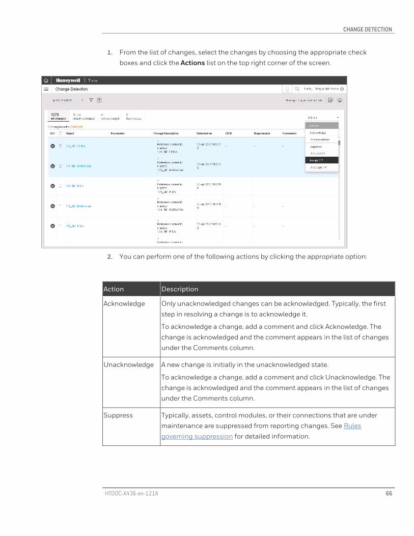
CHANGE DETECTION
HTDOC-X436-en-121A 66
1. From the list of changes, select the changes by choosing the appropriate check
boxes and click the Actions list on the top right corner of the screen.
2. You can perform one of the following actions by clicking the appropriate option:
Action Description
Acknowledge Only unacknowledged changes can be acknowledged. Typically, the first
step in resolving a change is to acknowledge it.
To acknowledge a change, add a comment and click Acknowledge. The
change is acknowledged and the comment appears in the list of changes
under the Comments column.
Unacknowledge A new change is initially in the unacknowledged state.
To acknowledge a change, add a comment and click Unacknowledge. The
change is acknowledged and the comment appears in the list of changes
under the Comments column.
Suppress Typically, assets, control modules, or their connections that are under
maintenance are suppressed from reporting changes. See Rules
governing suppression for detailed information.

CHANGE DETECTION
HTDOC-X436-en-121A 67
Action Description
A suppression list defines the time period between which suppression
must occur. Choose between existing suppression lists or create a new
one to apply.
To use an existing suppression list:
To suppress a change, click View Existing. A list of available suppression
titles appear. Click the one you want and click Suppress. The suppression
period defined by the suppression title are applied to the selected
changes.
To create a new suppression list, see Suppress changes.
Unsuppress When maintenance is complete, suppression imposed on control modules,
assets, or function blocks can be reverted to the unsuppressed state. Also,
automatic unsuppression happens when the suppression time period is
over.
To unsuppress a change, add a comment and click Unsuppress. The
change is acknowledged and the comment appears in the list of changes
under the Comments column.
Assign CR To assign a change request ID to a change. Select one or multiple changes
and from the Actions list, click Assign CR. In the ensuing window, type a CR
ID and click Assign. The ID appears under the CR ID column in the list of
changes.
Unassign CR To unassign a CR ID. Select one or multiple changes and from the Actions
list, click Unassign CR. In the ensuing window, type a comment and click
Unassign. The comment appears under the Comments column in the list
of changes.
3. Under the Object column is a link that you can click to see the logical view of the
selected object on which a change has occurred. This can aid you to analyze the
change. This link, takes you to the Logical View page. Note that you must return to
the Change Detection page and filter again to resume viewing other changes.

CHANGE DETECTION
HTDOC-X436-en-121A 68
9.5 Suppression
9.5.1 Rules governing suppression You may want to suppress assets, control modules, or their connections under
maintenance from reporting changes or engineering anomalies. You can easily select a
control module and specify a time period for which you want changes suppressed. After
the time period lapses, the control module becomes unsuppressed and resumes normal
behavior. There are eight rules governing suppression.
Snapshot Date What Changed?
Change Suppression Status
S-1 JAN-31
S0 FEB-28 CM1.PIDA.K Change C1
Suppression
period
MAY-30 to
JUL-31
S1 MAY-30 CM1.PIDA.T1 Change C2 In the
suppression
period,
changes C2,

CHANGE DETECTION
HTDOC-X436-en-121A 69
S2 JUL-2 CM1.PIDA.T1 &
CM1.PIDA.T2
Change C3
Change C4
C3,C4 will be
suppressed
After the
suppression
period lapses,
changes C1,
C2, C3,C4 will
be
unsuppressed
1. RULE 1: For a change to be suppressed, the Suppression List date range (From date,
To date), change date, and current date, are all considered.
2. RULE 2: If the current date is within the Suppression From and To dates, all changes
occurring between the From and To dates will be suppressed.
3. RULE 3: If the current date is after the Suppression To date, all changes will be
unsuppressed.
4. RULE 4: Suppression happens at an object level, that is, at the minimum container
level only and not at the basic block level. In a typical hierarchy of assets comprising
of Asset > Container Control Modules > Control Modules >Function Blocks, you can
suppress each level except the lowest level (Function Block level).
5. RULE 5: Asset change suppression will only suppress that asset. It will not suppress
changes on the tags under it. For example, if you suppress an asset, it will be
suppressed. However, the container control modules, control modules and function
blocks under it will continue to remain unsuppressed.
Asset A
CM_A
FB_1
FB_2
FB_3

CHANGE DETECTION
HTDOC-X436-en-121A 70
CM_B
FB_4
FB_5
Example: If you suppress Asset A, only Asset A is suppressed; CM_A, FB_1, FB_2, FB_3 will
not be suppressed.
ATTENTION
If you suppress Asset A, all associations with both CMs and all FBs will be suppressed. If you suppress CM_A, the blocks under it: FB_1, FB_2, FB_3, will be suppressed. Also, if you suppress FB_1, CM_A (the parent tag) will also be suppressed. Consequently, FB_2 and FB_3 are also suppressed.
6. RULE 6: When a connection or association is suppressed, the container that shows
up in the Object Name column alone gets suppressed. The other end will not be
suppressed.
Consider the following example. PIDA OP value is connected to PIDB SP. PVFORMAT value
of DACA of CM1 changes from D0 to D1. PVSOURCE value of DACA of CM2 changes from
Auto to Manual.
In this case, the following changes appear in the Change Detection page:

CHANGE DETECTION
HTDOC-X436-en-121A 71
No Object Parameter Description
1 CM1.PIDA OP CM1.PIDA.OP
CM2.PIDB.SP
2 CM2.PIDA SP CM2.PIDA.SP
CM1.PIDA.OP
3 CM1.DACA PVFORMAT DO DI
4 CM2.DACA PVSOURCE AUTO MAN
As you can see, the same change — the connection between CM1.PIDA.OP to
CM2.PIDB.SP is marked twice in the list of changes: one under CM1 and the other under
CM2. If you are suppressing this change, depending on whether you suppress the change
in CM1 or CM2, the suppression rules apply. If you suppress the change in CM1 (row 1 in
the above table), the corresponding change in CM2 will also be suppressed as CM1 is
involved in the connection. Additionally, change to CM1.DACA, will also be suppressed as
the CM to which it belongs (CM1) is suppressed but not row CM2.DACA (row 4).
Similarly, if you suppress the change in CM2 (row 2 in the above table), change under CM1
(row 1) will not appear as suppressed.
In this case, change to CM2.DACA will be suppressed as the CM to which it belongs (CM2)
is suppressed.
7. RULE 7: If either end container is suppressed, connections and associations involved
will also be suppressed.
In the above example, if you suppress either CM1 or CM2 itself, then both entries (rows 1
and 2 in the above table) will appear as suppressed.
8. RULE 8: A Suppression List must have a system associated with it. Only those
suppression lists pertaining to the selected system will appear and the changes under that will be shown under the View suppression list.
9.5.2 Suppress changes To suppress changes:
1. On the Trace Dashboard, click and select Change Detection.
2. Select a System. By default, changes to the selected system between the current and
previous snapshot are displayed.

CHANGE DETECTION
HTDOC-X436-en-121A 72
3. To filter the list of changes:
Click and use a combination of the available filter options. Click Filter.
or
Click and click a saved filter.
The list of changes based on your filter settings appears.
4. Select one or multiple changes you want to suppress.
5. Select Suppress from the Select Action list. The Suppression Title window appears.
Choose an existing suppression list or create a new one.
• If you chose an existing list, the From and To dates are selected. If the list
already has some suppressions, they are displayed on the right pane. Enter your
reasons for suppression in the Add Comment box.
ATTENTION
For suppression to work correctly, the following conditions must be met:
Suppression Start Date > UTC > Suppression End Date
Suppression Start Date > Timestamp of the change > Suppression End Date
Basically, the UTC and Timestamp of the change must fall within the Suppression Start and End dates for suppression to work correctly

CHANGE DETECTION
HTDOC-X436-en-121A 73
• If you want to create a new suppression list, click Create Title and enter a name
for the suppression list. Select From and To dates. The From Date is a list of
dates snapshots were collected. Select the To date using the calendar. Enter
your reasons for suppression in the Add Comment box.
6. Click Suppress. The change and its associated changes are suppressed. The
Suppression title you chose or created appears under the Suppression column.
Additionally, the suppressed changes will be available when you click Suppressed in
the Quick Filter section. See Rules governing suppression for detailed information and
understand what other changes will be additionally suppressed.
9.5.3 Manage Suppression List A suppression list is a list of changes that have been suppressed and is identified by a title
and the time period of suppression (From and To dates). When suppressing changes, you
can group related changes under a suppression list. Suppression lists can be created for a
selected system but not for a collection of systems. You can create a new suppression list
either when suppressing a change (see procedure) or independently (explained here).
To create a suppression list:
1. On the Trace Dashboard, click and select Change Detection.
2. Select a System. By default, changes to the selected system between the current and
previous snapshots are displayed.

CHANGE DETECTION
HTDOC-X436-en-121A 74
3. Click Manage Suppression Lists. Click the Create Title option and type a name for
the suppression list.
4. Select From date (a list of dates when available snapshots were collected). This is the
date from which selected changes will be suppressed. If current date is greater than
From date, changes that have occurred between From and Current date will also be
suppressed.
5. Select To date using the calendar. This is the date up to which selected changes will
be suppressed.
6. Enter reason for suppression in the Add Comment box.
7. Click Save. The suppression list is created. The next time you suppress a change, this
suppression list will appear as an option that you can use to suppress.

HTDOC-X436-en-121A 75
10 Change Requests
Honeywell Trace provides the ability to define a process through which change requests
and defect items flow before they can be worked upon. Termed a work order, the process is
defined by templates that you can select.
Be it changes that are requested or engineering anomalies that are detected, you can
define a work flow through which the items pass before they can be assigned to be
resolved. The work flow, called a Work Order, is based on pre-defined templates. The
templates specify the multiple states in the work flow, pictorial representation of how items
in a work flow move, alternate flows between states, users who can be assigned to each
state, and checklist of items that must be satisfied for a state to be completed.
In effect, a clear system can be established where each change being requested or each
defect that must be fixed is assigned to critical users, who verify the checklists present in
each state and approve only when check listed items are satisfied. After a work order is
completed, the same information is presented in the Change Detection and Engineering
Anomaly pages against the changes or anomalies that have passed through the work
order and have been completed.
10.1 Create Work Order To create a new work order:
1. On the Trace Dashboard, click and select Change Requests.
2. Click Create Work Order. The Create Work Order page appears.
3. Select a Template from the list of available templates. The Work Order Summary
appears providing a graphical representation of the work flow as defined by the
selected template. This pictorial representation has all the states within the work
order and the work flow between the different states.
4. Type a Work Order Name. This is mandatory.
5. Type a Brief Description of the work order you are creating. This is mandatory.
6. On the Work Order Summary, click a state (represented by a rectangular box) and
click the Select Users button. A list of users who you can assign this state to appears.
Note that only users belonging to PT Engineers and PT Managers will be listed.
7. Select the users and click Save Changes.

CHANGE REQUESTS
HTDOC-X436-en-121A 76
ATTENTION
Note that for every state except Approve, only one user (the creator themselves or any other user from the list of users) can be assigned.
Only for the Approve state, you can assign a maximum of 6 users.
For the Evaluate and Close states, the creator of the work order can assign it to themselves alone.
8. Repeat the previous step to click each state and assign users to each state.
9. After you have assigned users to each state, you must define the criticality of the user
for each state. Click the state on the Work Order Summary. The user or list of users is
displayed. Select the Critical or Optional radio buttons to mark the user's criticality
for that state.
ATTENTION
Note that Approve state is the only state to which you can assign a maximum of 6 users. Among these 6, you can assign Critical to a maximum of 3 users. For all other states, as only one user is assigned, you must assign that one user as Critical
10. Select a system from the Select System drop-down.
11. Under Requested For, you can select if this work order is for a Change or for an
Anomaly.
12. If you select Change, select if the changes are to be filtered based on Hardware or
Logical or None. If you choose Hardware or Logical, click the Browse button and
select a type from the resulting list. You can also type the first few letters of the item
you are looking for in the search field and click the Search icon to quickly locate the
type you are looking for. After you chose the type, enter at least 3 characters of the
tag name you are looking for. From the results, click the + button to select a
hardware/logical tag for which all changes will follow the work order you are now
creating. Note that you can add changes from different systems to the same work
order. Your selections are displayed on the right of the screen.
13. If you selected Anomaly in step 11, the list of anomalies for the selected system from
the latest available snapshot is displayed. Click the Filter icon and make selections
and click Filter to select the anomaly you are looking for. Select the anomaly by
selecting the corresponding check box. Note that you can assign either one anomaly
or multiple anomalies to a work order. Note that you can add anomalies from
different systems to the same work order. Your selections are displayed on the right
of the screen.

CHANGE REQUESTS
HTDOC-X436-en-121A 77
14. Click Next. The selections you have made are displayed.
15. Click Next. The details are saved and the work order details are shown. On the left
pane, you will see the work order's details while on the right pane are displayed the
work order summary.
16. Click Start Work Order and acknowledge the success message. The work order you
created is displayed in the list of work orders on the Work Order View page.
10.2 View list of Work Orders To view the list of work orders and their status:
1. On the Trace Dashboard, click and select Change Requests.
2. The Work Order View page appears with the list of work orders. Information about
each work order is presented in a tabular format.
• Date
• Work Order Id
• Work Order Name
• Description
• Created By
• Status
3. Click a work order to view its details. Under the Status tab, on the left pane, you will
see information about the work order.
4. On the right pane, the work flow is presented in a pictorial format. Clicking a stage in
the work flow displays the information pertaining to that stage at the bottom of the
right pane.
5. If you are a user who has been assigned a stage in the work order, you can modify
information after taking necessary action. You can also click the Complete or other
decision buttons such as On-Hold, ReSubmit and so on to convey your decision on
the completeness of the stage you have been assigned. If you mark a stage as
Complete, the work order progresses to the next stage.

CHANGE REQUESTS
HTDOC-X436-en-121A 78
ATTENTION
If you are the only critical user assigned to a stage, if you mark the stage as Complete, the work order moves to the next stage. If you are one of multiple critical users (maximum of 3 users can be assigned as critical users), only after all critical users have approved by clicking the Complete button will the stage be marked as completed.
A stage that is completed will be marked in green color on the pictorial representation of the work order template.
6. Click Close to close the work order you are viewing and return to view the list of all
work orders.
10.3 Work on states assigned to you in a work order If you are assigned as a critical or optional user for one or multiple states in a work order,
you can view the state you are assigned to, take appropriate action, mark the items in the
checklist, and approve the state.
Note that if you are one of multiple critical users for a state, only if all critical users mark
the state as Complete, you will be able to complete the state.
To take action on a work order assigned to you:
1. On the Trace Dashboard, click and select Change Requests.
2. The Work Order View page appears with the list of work orders. Click a work order that
is in Created or In Progress state.
3. The details of the work order along with the Work Order Summary appears. States
that are already completed are marked in green, while the state in which the work
order is in currently is marked in orange. Click the state marked in orange in the Work
Order Summary.
4. The details of the state are displayed below. Based on the selected state, you are
provided text fields to fill and options to select to indicate the readiness of the state.
After careful verification, mark your answers for items in the checklist.
5. Add comments, attach supporting files, if necessary.
6. Click Complete if you agree that the work order is ready to progress to the next state.
Where additional work is required, you can use the other decision buttons such as
On-Hold, ReSubmit and so on to convey your decision on the completeness of the
stage to the assigner.
7. You can click the next state, if it is assigned to you, and take action and repeat steps
4 through 6.

CHANGE REQUESTS
HTDOC-X436-en-121A 79
8. If you click the Reject button, the work order is closed no matter in what state it is in.
The work order is listed in the Work Order View page with its status marked as
Rejected.

ENGINEERING ANOMALY
HTDOC-X436-en-121A 80
11 Engineering Anomaly
Control and instrumentation systems have mistake proofing mechanisms; many
unsupported configurations are blocked during configuration. However, there are cases
when configurations are not blocked by the system yet they are a violation of the control
philosophy, design rule, configuration rules of that plant. Control philosophy may differ
across plants, hence design rules may not be the same. It then becomes impossible to
detect such engineering anomalies.
Trace detects all such engineering anomalies. It even provides options to define
engineering anomalies for plant-specific control philosophy, design rule, and
configuration rules. After detecting such violations in the form of engineering anomalies,
they are assigned to the concerned maintenance personnel for rectification.
Engineering Anomalies are detrimental to the functioning of any control system and are
therefore immediately attended to. Although considerable time and effort is spent to
resolve engineering anomalies quickly, the same is found wanting when it comes to
documenting the anomaly: its cause, resolution time, resolver, and other such important
information. Even if such documentation exists, it is often in a physical format that is
neither stored in a central location nor is easily searchable. Incomplete documentation
compounds the problem. Without a system to manage engineering anomalies,
dependability on human assets and their experience becomes a necessity.
Communication and tracking of engineering anomalies is dependent on e-mail chains and
verbal instructions that may lead to a loss of accountability.
Trace provides an effective yet simple anomaly management system. It provides a
centralized location to define, create, sort, store, and assign engineering anomalies. With
the ability to provide resolution notes, and view history of an anomaly, analysis becomes
easy when an anomaly recurs. As successive snapshots provide information of all open,
resolved, and even reopened engineering anomalies, complete traceability for an anomaly
since the very beginning, is achieved. System-defined and user-defined rules to identify
engineering anomalies provides a very fine sieve through which to weed out anomalies. As
Trace gives the ability to provide notes and assign engineering anomalies to operators and
engineers, communication and tracking of engineering anomalies with greater
accountability is easily achieved.

ENGINEERING ANOMALY
HTDOC-X436-en-121A 81
11.1 Filter engineering anomalies As the engineering anomalies reported in a system are possibly in multiples of thousands,
filtering them to view only the desired ones becomes a necessity.
Trace offers three criteria to filter engineering anomalies in a system:
• Anomaly Name: Broadly, engineering anomalies can be classified as:
• Pre-defined: Certain rules are pre-defined that are used to identify engineering
anomalies when the snapshot of the control system database is created. Based on
the rule violated, every anomaly is assigned the appropriate name. Example: In an
Experion system, a pre-defined anomaly name is Missing peer references. All tags
that have missing peer references are classified under the name Missing peer
references.
• User-defined: In addition to pre-defined rules, you can define system-wide rules for
single or multiple objects. Example: Let’s say you define an anomaly: Incorrect tag
naming convention and select Input Output Modules (IOMs)and IOs as objects.
When a snapshot is collected, all IOMs and IOs that violate the tag naming

ENGINEERING ANOMALY
HTDOC-X436-en-121A 82
convention that you have set appear as engineering anomalies under the head
Incorrect tag naming convention.
When the snapshot of the control system database is created, pre-defined and user-
defined rules are used to identify engineering anomalies. Every anomaly is then assigned
an anomaly name based on these rules. The anomaly names and their number vary
depending on the control system as described here.
System Defect Names
Safety Manager FLD not assigned to anomaly
Missing FLD references from Tag
Missing FLD to FLD references
Experion Missing Asset on Tags
Missing peer references
Multiple write to same tag parameter
Disabled Alarms
TPS Missing peer references
Multiple write to same tag parameter
• Actions Taken: Engineering Anomalies classified based on one of seven possible
actions you could take.
Action Taken Description
Acknowledged The anomaly has been acknowledged.
Unacknowledged Engineering Anomalies that have not been acknowledged.
Assigned Engineering Anomalies assigned to the concerned personnel.
Unassigned Engineering Anomalies that have not yet been assigned.
Resolved Engineering Anomalies that have been resolved.
Suppressed Engineering Anomalies that have been suppressed. Typically, assets,
control modules, or their connections under maintenance are suppressed
from reporting engineering anomalies.
ENGINEERING ANOMALY
HTDOC-X436-en-121A 83
Action Taken Description
Unsuppressed Operators can unsuppress engineering anomalies manually.
• Priority: Engineering Anomalies that have been assigned one of three priorities
based on their severity.
Priority Description
High Engineering Anomalies graded as high priority by pre-defined rules by the
respective system.
Medium Engineering Anomalies graded as medium priority by pre-defined rules by
the respective system.
Low Engineering Anomalies graded as low priority by pre-defined rules by the
respective system.
You can mix and match filters to zero in on the engineering anomalies that you are
interested in.
11.1.1 Save Filter If you have a particular filter criteria that you often use, save and reuse those filter settings
by creating a custom filter. To create and save a custom filter, see Filter and view
engineering anomalies. To use a custom filter, click and select the required filter.
All these saved filters are available for selection when creating a report package on the
Reports page.
11.1.2 Quick Filter You can use the quick filter to sort all engineering anomalies, high priority, unresolved,
unassigned, or suppressed engineering anomalies.
11.1.3 Export engineering anomalies
To export the list of engineering anomalies based on the applied filter, click , type the
file name, and click OK to generate a .csv file.

ENGINEERING ANOMALY
HTDOC-X436-en-121A 84
11.1.4 Print engineering anomalies
To print the list of engineering anomalies based on the applied filter, click , select
graphical view, tabular view, or both, and click Print. Specify appropriate print settings
along with options to print headers and footers and background graphics.
To print the list of engineering anomalies based on the applied filter to paper, XPS, or PDF
formats, click . To print to XPS or PDF formats, your printer must be configured
appropriately. See the How to print large diagram from PDF section for print settings
required for printing large diagrams.
11.2 Filter and view engineering anomalies To filter engineering anomalies in a selected system for a selected snapshot.
1. On the Trace Dashboard, click and select Engineering Anomaly.
2. Select the Snapshot from the drop-down list. A list of all engineering anomalies for
the selected system is displayed.
3. The quick filter on the top left of the screen provides links to quickly view All
engineering anomalies, High Priority, Unresolved, Unassigned, or Suppressed
engineering anomalies along with the anomaly count for each category. Click a link
to sort the list based on your selection.
4. To customize the filter based on anomaly name, Actions taken or Priority, click
and in the ensuing window, provide your filter criteria. See Filter Engineering
Anomalies for more information.

ENGINEERING ANOMALY
HTDOC-X436-en-121A 85
5. Click Save Filter and provide details if you want to save this selection for future use.
6. Click Filter. The list of engineering anomalies based on your filter criteria is displayed
in a tabular format with the following information.
• Status: The current status of the anomaly: acknowledged/unacknowledged,
assigned/unassigned, resolved/unresolved,
• Suppressed: Indicates if the anomaly is suppressed or unsuppressed
• Anomaly Name: The self-explanatory anomaly name that is based on a
predefined rule that was used by the system to create this anomaly.
• Defect Type: Indicates if it is a system defined or user-defined anomaly type.
• Priority: System defined priority for the anomaly based on its anomaly name.
• Description: A brief description of the anomaly.
• Assigned to: Person assigned to resolve this anomaly. Must be a registered user
created in the Domain Controller of user type PT Engineer or PT Manager.
ENGINEERING ANOMALY
HTDOC-X436-en-121A 86
• Identified Date: Date when the anomaly was identified.
• Selected Snapshot: Indicates if an anomaly is found in the snapshot.
• Comments: Click a comment to view five of the latest comments, actions taken,
and persons who have taken action.
11.3 Act on engineering anomalies When an anomaly is raised, personnel act upon it by selecting an anomaly from the list of
engineering anomalies and taking of nine actions from the Select Action list on the top-
right corner of the screen.
To act on an anomaly, select the check box corresponding to one or multiple engineering
anomalies you want to take action on. From the Select Action list, click one of nine
possible actions as described here.
Action Description
Acknowledge Only unacknowledged engineering anomalies can be acknowledged.
Typically, the first step in resolving an anomaly is to acknowledge it.
Unacknowledge A new anomaly is initially in the unacknowledged status.
Suppress Typically, assets, control modules, or their connections that are under
maintenance are suppressed from reporting engineering anomalies.
Unsuppress When maintenance is complete, suppressed engineering anomalies can
be reverted to unsuppressed status.
Assign To assign an anomaly to a resolver. Click Assign and in the ensuing
window, select an assignee from the Select User list. It is mandatory to
enter notes in the Comment text box; this is typically information that aids
the assignee to resolve the anomaly. Click Assign and acknowledge the
message indicating a successful assignment.
Unassign To unassign an assigned anomaly. Click Unassign. It is mandatory to
provide notes explaining your action. Click Unassign and acknowledge the
message indicating the anomaly is successfully unassigned.
Reassign To reassign an assigned anomaly. Only assigned engineering anomalies
can be reassigned. It is mandatory to provide notes explaining your action.
Click Reassign and acknowledge the message indicating the anomaly is
successfully reassigned.

ENGINEERING ANOMALY
HTDOC-X436-en-121A 87
Action Description
Resolve After an anomaly has been successfully resolved, the assignee changes its
status to resolved. It is mandatory to provide resolution notes. Click
Resolve and acknowledge the message indicating the anomaly is
successfully resolved.
Unresolve If an anomaly’s resolution is found to be unsatisfactory, its status can be
changed to unresolved. Only resolved engineering anomalies can be
unresolved. It is mandatory to provide notes on why the status is being
reverted to unresolved. Click Unresolve and acknowledge the message
indicating the anomaly is successfully reverted to unresolved state.
11.4 Custom Engineering Anomalies In addition to pre-defined rules that are used to identify engineering anomalies in a
system, Trace offers customization by enabling you to define your own rules to identify
system-wide engineering anomalies.
For example: say a cluster in an Experion system has multiple C300 controllers. Let’s say
you have a naming convention for C300 controllers named ‘Incorrect tag name’ defined
as: C300_<two digit cluster number>_<three digit serial number>. After snapshot collection,
if any C300 controller in the cluster does not follow this naming convention, it is flagged as
an anomaly under the anomaly name ‘Incorrect tag name’.
You can define your own anomaly name, specify one or multiple rules to it, set its priority,
and add objects that will be checked for the rules you have specified. Engineering
Anomalies collected under this name can also be prioritized by assigning them one of 3
priorities. After you define a custom anomaly and enable it, Trace immediately displays
items that violated your custom defined rule in the list of engineering anomalies.
Users with delete permissions or the person who created a custom anomaly can also
disable custom engineering anomalies. However, if there is any anomaly in the database
per the anomaly definition, a custom anomaly cannot be deleted.
These custom engineering anomalies are applicable to a system type. For example: you
can have a custom anomaly to identify wrong tag naming convention for an Experion
system and another for a TPS system and so on.
11.4.1 Create a custom anomaly To create a custom anomaly:
1. On the Trace Dashboard, click and select Engineering Anomaly.

ENGINEERING ANOMALY
HTDOC-X436-en-121A 88
2. Select the Snapshot from the drop-down list. A list of all engineering anomalies for
the selected system is displayed.
3. Click the Custom Anomaly button. You can define conditions that will be treated as
anomalies under 4 tabs:
• Tag Name Convention: Specify tag naming convention for the selected system.
You can create multiple rules and assign objects to each rule. For the rule, specify
the number of characters in the tag name and if the characters ought to be
alphabetical or numerical or a combination in a specified format.
• Switch Model (Applicable to Experion & ESVT systems only): Specify those Switch
Model - Experion version combinations that you want to flag as anomalies. These
switch model number - Experion version number combinations will be blacklisted
and all occurrences of this combination will be flagged as anomalies the next time
data collection is performed.
• Switch IOS Version (Applicable to Experion & ESVT systems only): Specify those
IOS versions that Cisco and HP Switch models are running whose information you
do not want to flag as anomalies. The information reported by switch IOS versions
you specify here will not be flagged as anomalies. Conversely, those version
numbers that are not in this list will be flagged as anomalies the next time data
collection is performed.
• Anomaly Settings: Specify the Availability and Priority status for the list of
anomalies.
11.4.2 Tag Name Convention

ENGINEERING ANOMALY
HTDOC-X436-en-121A 89
1. Under the Tag name convention tab, a list of pre-defined and user-defined anomaly
names is visible. This will be empty if there are no custom rules added yet.
2. Click the + icon on the right. A new entry is added on the left pane. On the right pane,
you have controls to define the rules for your convention:
• Select Objects: Click this list and select one or multiple objects this rule will
apply to.
• No. of characters for tag: Click inside the box and use the up/down arrows to
add up to a maximum of 32 characters you want to define. Based on the
specified number, boxes are shown below where you specify the characters that
form your naming convention: alphabets, numeric, or special characters.
• Name convention: Provide a clear, identifiable name for the tag naming
convention.
• Set Priority: Select from one of 3 options: High, Medium, or Low.
3. To add another rule to the same naming convention, click Add Rule corresponding to
the tag naming convention and repeat steps 4 and 5.
4. Click Close.
11.4.3 Switch Model (Applicable to Experion & ESVT systems only)
1. Click the Switch Model tab.
2. Click the + icon on the right. A new entry is added on the left pane. On the right pane,
you have controls to define the rules for your convention.

ENGINEERING ANOMALY
HTDOC-X436-en-121A 90
3. Provide the following information:
• Switch Model Anomaly Name: The name for your rule.
• Set Priority: Select High, Medium, or Low priority.
• Anomaly Description: A brief description.
• Release Number: Applicable only for Experion systems. The version you select
here and later versions will be used to define the rule. Example: If you select
432.x, versions of Experion 432.x and later will be selected to apply this rule.
• Switch Model Number: Specify the model number of the Switch and click the +
button. Click the - button to delete a switch.
4. Click Done. The rule you added is saved. Repeat these steps to add multiple rules
based on your requirement.
Example
Here is an example to understand creating a Switch Model anomaly.
Switch Catalyst 2950 is the qualified switch for running Experion R400.
Catalyst 2960 is the qualified switch for running Experion R430.
To detect a switch model and Experion version mismatch, you must specify a Switch
Model rule where in you specify Catalyst 2950 as the switch model and Experion R410 as
the Experion version. Consequently, any combination of Catalyst 2950-Experion R430 (or
later) will be flagged as anomalies.
11.4.4 Switch IOS Version (Applicable to Experion & ESVT systems only)

ENGINEERING ANOMALY
HTDOC-X436-en-121A 91
1. Click the Switch IOS Version tab.
2. Click the + icon on the right. A new entry is added on the left pane. On the right pane,
you have controls to define the rules for your convention.
3. Provide the following information:
• IOS Version Anomaly Name: The name for your rule.
• Set Priority: Select High, Medium, or Low priority.
• Anomaly Description: A brief description.
• Switch Models: Click the Cisco and HP links, and click the + button to select the
models that you want to be a part of this rule. The models you add are displayed
on the right. Note that the model numbers you add to this rule will be part of a
whitelist of models whose data will be allowed. Conversely, it means that the
models that are not selected here will be blacklisted and the information coming
from such models will be flagged as anomalies the next time data collection is
performed.
4. Click Done. The rule you added is saved. Repeat these steps to add multiple rules
based on your requirement.
Example
Here is an example to understand creating a IOS Switch Version anomaly.
Let's say on the Catalyst-2960-24tc-l-switch, only IOS versions 15.2(2), 15.2(3), 15.2(4)
are qualified.
To detect a Switch IOS Version anomaly, you must specify that only IOS versions 15.2(2),
15.2(3), 15.2(4) on the switch Catalyst-2960-24tc-l must be allowed. If any other IOS
version is detected, it must be flagged as an anomaly.
11.4.5 Anomaly Settings
1. Click the Anomaly Settings tab.

ENGINEERING ANOMALY
HTDOC-X436-en-121A 92
2. Select an anomaly name from the list on the left. Click the Set Availability button and
select Enable or Disable and click Set. For the same anomaly, click the Set Priority
button and select High, Medium, or Low and click Set.
3. The anomaly list is updated with the availability and priority you have set.
4. Click Done.
Based on the pre-defined and user-defined engineering anomalies that are enabled,
control objects not meeting the defined criteria will be flagged under the appropriate
anomaly name with the defined priority in the list of engineering anomalies.
Delete custom engineering anomalies
You can delete custom engineering anomalies only if no engineering anomalies exist in
the database based on the anomaly definition. Even if a single anomaly exists based on
this definition, the custom anomaly will not be deleted.
To delete a custom anomaly, first delete all the rules that are defined under it. After all rules
are deleted, the custom anomaly is also deleted.

SPARES
HTDOC-X436-en-121A 93
12 Spares
Trace enables you to utilize all channels in your plant effectively by providing means to
track and create an inventory of used and available IOs. By allowing users to mark
channels reserved for their own projects, spurious choices of reserving the same IO
channels by other users is eliminated. Unused channels that had been marked for use in a
project can be utilized by others needing them thus enabling full utilization of hardware
resources. Measures provided to reconcile resources claimed by 2 separate users or
projects leads to greater efficiencies in resource utilization. When a project is completed or
based on your needs, channels can be freed up and made available to users or projects
needing them leading to economy and efficiency in using resources to the maximum
extent possible saving wasted time and effort in resolving hardware resource conflicts. The
inventory also enables you to better forecast and plan the finite resources available in any
given plant.
Read More >>
12.1 Filter spares You can filter channels based on the following multiple criteria:

SPARES
HTDOC-X436-en-121A 94
• Project: Usage in a project.
• Controller name: Name of the controller
• IOM name: Name of the IOM
• Channel name: Name of the channel
• Status: One of many of 4 available statuses:
• Free
• Reserved
• Used
• Conflict:
• Type: One of the multiple IO types applicable for a system and that are in use
• Reserved by: User reserving the spare
You can provide a combination of the multiple criteria to effectively locate your channels
within or across projects.
12.1.1 Save Filter If you have a particular filter criteria that you often use, save and reuse those filter settings
by creating a custom filter. To create and save a custom filter, see Filter and view channels.
The filters that you save are available for selection when creating a report package on the
Reports page.
12.1.2 Quick Filter You can use the quick filter to sort channels based on status: Free, Reserved, or Used.

SPARES
HTDOC-X436-en-121A 95
12.1.3 Export spare list
To export the list of channels, click , type the file name, and click OK to generate a csv
file.
12.1.4 Print list of spares
To print the list of channels, click , and click Print. The filtered list you have selected
(All, Free, Reserved, or Used) is printed. See the How to print large diagram from PDF
section for print settings required for printing large diagrams.
12.2 Filter and view spares To filter spares:
1. On the Trace Dashboard, click and select Spares.
2. Select a System. By default, any changes to the IOs between the current and previous
snapshots are displayed.
3. The quick filter on the top left of the screen provides links to quickly view spares
based on status: Free, Reserved, or Used, along with the count for each category.
Click a link to sort the list based on your selection.
4. To customize the filter, click and in the ensuing window provide your filter
criteria. See Filter spares for more information.
5. Click Save Filter and provide details if you want to save this selection for future use.
6. You can choose a combination of filter options to match the changes you are looking
for. Click Filter. The list of changes based on your filter criteria is displayed in a
tabular format with the following information.
• Channel Name
• IOM Name
• Controller Name
• Channel Type
• Reserved By
• Status
• Project Name
• Comments

SPARES
HTDOC-X436-en-121A 96
12.3 Actions Typically, channels can be in one of 3 states: Free, Reserved, or Used. When you collect the
first ever snapshot of a system, the channels will be in either Free or Used state based on
their usage. You can then create projects and assign spares (Reserve) to projects. When a
subsequent snapshot is collected, you will have Free, Used, and Reserved spares.
However, a Conflict status is reported if a channel that has been reserved in Trace but has
been deleted (in the field) or if a channel has been reserved but is used in the field. In the
former case, the channel will be deleted, while in the latter case the channel will be marked
as used.
You can take action to free up a channel, reserve a channel, or reconcile a channel in
conflict.
• Reserve: Only Free channels can be reserved. You reserve a channel to a project
that in turn can have multiple systems associated to it.
• Free Up: Only Reserved channels can be freed up.
• Reconcile: Channels that are in Conflict alone can be reconciled. If a channel is in
Conflict state and is reconciled, then its status will change to Used.
12.3.1 Create Project By default, only users with Manager level access can create a project.
Before users with Engineer level access can take action on any channel, a user with
Manager level access must first create a project and assign systems to that project.
To create a project:
1. On the Trace Dashboard, click and select Spares.
2. Select a System.
3. Click the Projects button on the top-right of the screen.
4. Click Create new project.
5. Click the Select systems drop-down and select one, multiple, or all systems you want
this project to be a part of.
6. Provide a Project Name.
7. Provide a brief Description.
8. Click Create. The project you created appears in the Projects window.
9. Click the close button to close the Projects window.

SPARES
HTDOC-X436-en-121A 97
12.3.2 Delete Project Either a user who has created a project or a user with delete permission can delete a
project. When a project is deleted, all spares reserved to that project will change status to
Free.
12.3.3 Act on spares When you want to take action on channels belonging to a system, you choose the channel,
then choose a project, and then choose an action you want to perform. Note that a project
can have multiple systems assigned to it.
NOTE
You must have Engineer level access to take action on spares.
To take action on a spare:
1. On the Trace Dashboard, click and select Spares.
2. Select a System.
3. Select the spares that you want to act upon.
4. Click the Actions drop-down list and select an option.
5. Reserve: Select one or multiple free spares and click Reserve. Select a Project from
the drop-down list. Add a comment, and click Reserve. The status of the spares
changes to Reserved as indicated by a Cyan colored R icon.
6. Free up: Select one or multiple reserved spares and click Free up. Acknowledge the
confirmation message and click OK. The status of the spares changes to Free as
indicated by a Green colored F icon.
7. Reconcile: Select one or multiple spares in conflict and click Reconcile.

QUERY
HTDOC-X436-en-121A 98
13 Query
Function blocks are the typical building blocks of any (C&I) system. These function blocks
are in possible multiples of thousands within any given system. Each function block has
multiple parameters. Often, a need is felt to search for a parameter or a set of parameters
within or across assets and control modules matching a particular value or expression and
having a particular output value or type. Examples: all PIDs that are in Auto mode; PV High
alarms in a selected system, and so on.
Trace’s Query feature provides very detailed filtering criteria to select and view parameters
you are interested in. And you don’t need expertise in SQL to create and run queries. Trace
simplifies and provides simple UI controls to create and execute even the most complex
queries. From the possibly hundreds of thousands of parameters (of function blocks and
control modules), you can query for a single parameter or a group of parameters based on
a combination of these search criteria:
• Criteria: Point name, asset, controller or type the block belongs to.
• Expression: Conditions on values of some parameters of the block.
• Output: Parameters of matching blocks whose values need to be displayed.
For the query you provide, validate and see the errors your search criteria could be creating
and take corrective action, save your search query so that you can run a report based on
this filter, and run the query to view parameters that match your criteria.
13.1 Run queries To run queries in a selected system for a selected snapshot.
1. On the Trace Dashboard, click and select Query.

QUERY
HTDOC-X436-en-121A 99
2. Select the needed Snapshot from the drop-down list. The latest snapshot is the
default selection.
3. Select a System from the list.
4. Provide Criteria information. To select available options, click where applicable. In
the ensuing pop-up window, narrow down available options by typing the first few
letters of the item you are looking for. Select relevant check-boxes and click Set.
• *Point Name: Type the point name or few letters of the point name; use wild card
characters ? and * appropriately.
• Assets: If you know the asset name, select it from this list. Assets belonging to
the selected system are listed here.
• Controllers: If you know the controller, control module name, select it from this
list. Controllers belonging to the selected asset are listed here.
• Types: Point types belonging to the selected controller are listed here.
5. Provide Expressions information: Select available parameters and create an
expression to single out the parameter you are looking for. Example: SCALEPERIOD
whose value is equal to 60 for a selected asset or control module.
• Parameters: To narrow down available options, if you know the parameter type,
enter few letters of the type. Example: type “og” to bring up Analog point. From
the ensuing list of parameters, select the required parameter and click Set.
• Condition: Conditional statements to form your expression.
• Value: If you are looking for an item with a particular value, type the value here.
Example: Analog point with value 4. Type 4 here.
• Query String: The expression you create is displayed here. You can repeat 5 to
create a more complicated expression to narrow down the parameter you
require. Example: A1Source =4 OR A1Source > 4.
6. Provide Output information:
• Parameters: Choose the output parameter type. Click and in the Type box,
enter the first few letters of the output type of the parameter. The list underneath
it narrows down. Make your selection. Now select the single or multiple output
parameters for the selected Type. The selected parameters are shown in the
Sequence list. Click X to remove a parameter and make a fresh selection. Click
Set to save the output parameter information.
• Save Query: Type a name to save this query. You can generate a report from the
Reports page for these saved queries.

QUERY
HTDOC-X436-en-121A 100
• Description: Provide a brief description to identify the saved query.
7. Click Validate. The query criteria you have provided are validated and a list of errors
with error codes is displayed.
8. Click the down arrow button (v) on top to return to the query page.
9. If you are satisfied with the validated result, click Run Query to view the results in a
tabular format.
10. Use the Export or Print buttons to export the results to a file or print out the results.
13.2 Defining a query You must enter the point name to be searched in the Point Name field while defining the
query. However, the other fields are optional. In addition, filters are also available to further

QUERY
HTDOC-X436-en-121A 101
refine your query. The available filters are asset, parent, and block type. The query results
vary based on the data entered in the other fields and the selected filters.
You can also use a selection list file as a point name. You can create a selection list file
using the defined format or use the selection list file that is generated from other
applications.
13.3 Guidelines for defining a query The following tables provide detailed information of all the fields and the filters in the
Query Definition page.
Field/Hyperlink name
Description
Point Name Enter the point name to be searched for. Example: CM_1. This is a
mandatory field.
You must adhere to the following guidelines while entering the point
name.
You can type the exact point name or point name with pattern
matching characters. Example: CM_1*, CM_1?, CM_1.PID*,
CM_*.PIDA, CM_*.PID*
You can also type the basic block names. Example: CM_1.PIDA.
You must separate multiple names by delimiter characters. The
delimiter characters are comma (,), semicolon (;), and space ( ).
Description Enter a user-friendly description of the query. The description must
not exceed 500 characters.
Example: List all CMs containing PID blocks.

QUERY
HTDOC-X436-en-121A 102
Field/Hyperlink name
Description
Expression Enter parameter conditions for the query using expressions.
Expressions can contain conditional operators and/or logical
operators.
The parameter used in the left-hand side (LHS) must be the
parameter on the expected result point’s block type.
Example: (T2 > 0.0 AND T1 > 1.0) OR CLTEQN = "EQC" OR CTLEQN =
"PROFITLOOP"
After defining the expression, you must click to add the expression
Output Parameters Enter the parameters of the points being searched, for which the
values must be displayed in the search results.
Example for defining output parameters: DESC; CTLEQN; T1; T2;
GAINHILM
Note: The non-applicable parameters are differentiated in the output.
For example, if the expected result tag is a control module (CM_1) and
MODE
Asset Select the assigned asset name based on which the result tags must
be filtered.
You can also browse for the assets loaded to the Experion server and
select them using the point picker.
Parent Select the assigned parent name based on which the result tags must
be filtered. The parent can be the name of the controller, interface
module, execution environment, or a link. You can also browse for the
loaded top-level hardware blocks and their execution environment
blocks loaded to the Experion server and select them using the point
picker.
Type Select the block type based on which the result tags must be filtered.
You can also browse for the block types defined in the Experion server
and select them using the point picker.
13.3.1 Guidelines for defining condition expression in a query This section summarizes the guidelines for entering condition expression and also
representing parameter data types in the condition expression.

QUERY
HTDOC-X436-en-121A 103
Entering condition expression
You must adhere to the following guidelines while entering the condition expression.
• The condition expression must be in the format left-hand side (LHS) (conditional
operator) right-hand side (RHS). LHS of the condition expression is the exact
parameter name and RHS of the condition expression is either the value of the
parameter or the exact parameter name.
• You can use the following conditional operators in the condition expression: > -
Greater than; < - Less than; = - Equal to; <= - Less than or equal to; >= - Greater than
or equal to; <> - Not equal to; &= - Contains; LIKE - string pattern matching.
• You must define multiple conditional expressions using the logical operators AND,
OR, and/or NOT.
• The precedence of evaluating expression can be altered using parenthesis operator
“( )”.
• You must define array parameter in the format PARAMNAME[(index1)][(index2)] in
both LHS and RHS of the expression where index1 and index2 are the absolute
indices.
• You can also browse for the target point parameters in condition expression
definition using the point picker.
13.3.2 Representing parameter data types in condition expression Trace recognizes only three data types– Integer, Float and String. Data types from different
source systems are mapped to one of these.
ATTENTION
For Boolean, Enum, Date time parameters. In Experion, Boolean and Enum parameters can be compared with both string and numeric values (like ALMENBSTATE = “ON” or ALMENBSTATE = 1). However, in Trace only their String values are stored. You must always know the valid string values and use them. Similarly, different systems have different date and time formats and they are stored as pure strings in the Trace database. Hence, you must know the date and time format to use such parameters in expressions.
13.3.3 Errors This is a table of possible error messages and a brief description for them.

QUERY
HTDOC-X436-en-121A 104
Error Message Description
ERR_BRINTERNALERROR Search aborted due to internal
browser error. Check log for details.
ERR_STOPINPROGRESS This operation cannot be performed
at this moment. Please try after some
time.
ERR_BRCONDPARAMDOESNOTEXIST Condition parameter referred does
not exist on the point.
ERR_BROUTPUTPARAMREADERROR Error reading value for output
parameter on point.
ERR_BRCONDPARAMREADERROR Error reading value for condition
parameter on point.
ERR_BRCONDITIONERROR Error evaluating expression on point.
ERR_BROPERATORINCOMPATIBLEWITHPARAM The comparison operator not valid
for parameter with this data type.
ERR_BRDATATYPEINCOMPATIBLEWITHPARAM Data type incompatibility in the left
hand side and right hand side of the
expression.
ERR_BRLHSNOTAPARAMETER Condition is invalid as left hand side
is not a parameter.
ERR_BROUTPUTPARAMDOESNOTEXIST Output parameter does not exist on
the point.

REPORTS
HTDOC-X436-en-121A 105
14 Reports
Trace provides ease of creating, scheduling, generating, and viewing reports consisting of
information about the control and instrumentation (C&I) system. This powerful feature
enables you to include different systems, clusters, queries relating to changes, engineering
anomalies, and parameters, within specified date ranges, immediately, or in perpetuity.
With pre-defined templates that are also highly customizable to include user-defined
logos, headers, and footers, Trace generates reports that can serve as historical
repositories of system data or for audit purposes. These reports can be exported to PDF.
Settings used to generate reports can also be reused to run reports whenever required.
You can generate and view five types of reports.
Report Description
System Performance
Report
Cluster-wise system performance reports for Experion systems alone
are currently supported. These reports are generated only for those
Experion clusters for which you have:
A valid license for generating a System performance report
Configured the Experion system and ensured that the System
performance file option is selected
Configured Global Advance settings
Scheduled a snapshot such that a minimum of 28 hours’ time is
available for the System performance file to be created.
The System performance file that is the source for this report is
generated and placed at a user-specified location on the Flex node.
During snapshot collection, Trace can be configured to pick this file to
generate the System performance report. If a single Flex node has
multiple System performance files, it is recommended you save each
cluster’s System performance file in a separate folder. Using Trace’s

REPORTS
HTDOC-X436-en-121A 106
Report Description
reports feature, you can view System performance reports in the PDF
format.
If after all conditions have been satisfied and the System performance
report still cannot be generated, verify if the McAfee Virus Scan
Command Line tool has been installed. See the Trace Installation
Guide for more details.
Changes report Report of changes that have occurred on a selected system based on
a selected filter.
Users create filters to view changes they are interested in. In creating
these filters, multiple criteria such as the time period, change type,
change status, and so on are specified. You can select such filters and
export their results as change reports.
Engineering
Anomalies report
Report of engineering anomalies that have occurred on a selected
system based on a selected filter.
Users create filters to view engineering anomalies they are interested
in. In creating these filters, multiple criteria such as the time period,
anomaly type, anomaly status, and so on are specified. You can select
such filters and export their results as anomaly reports.
Spares report Report of spares (used, free, reserved channels) based on a selected
filter.
If you have a particular filter criteria that you often use, save and reuse
those filter settings by creating a custom filter. To create and save a
custom filter, see Filter and view channels.
Users create custom filters to view list of used, reserved, or free spares.
In creating these filters, multiple criteria such as the project, controller
name, IOM name, channel name, status, type, and so on are specified.
You can select such filters and export their results as spares reports.
Queries report Report of queries that users have performed on a selected system.
Users specify multiple criteria to search for parameters they are
interested in. You can use these search criteria and export their results
as queries reports.

REPORTS
HTDOC-X436-en-121A 107
When you access the Reports page the first time after data collection, IAA reports for
Experion clusters (provided they were enabled during data collection) are the only reports
you will see.
The following table is a role matrix with respect to permissions for working with reports.
Global Groups LSS-PT Product admin
LSS-PT Engineers
LSS-PT Managers
LSS-PT Report Users Actions
Create report package x x
Schedule report
package x
Run report package x
Delete report package * x
* - Deletion allowed only if the report was created by the same user.
14.1 Create Report Package A report package contains details about the report type(s) you want included in a single
report, its schedule, and the template in which it will be presented. Report packages enable
you to specify settings that you can use to generate reports.
This procedure provides information on how to configure changes, engineering anomalies,
spares, and queries reports. It includes instructions to define report templates and
scheduling them.
To create a report:
1. Open the Trace application, click and select Reports under Manage. The
Reporting page appears displaying the available report packages.
To edit an available package, click the package name and follow steps 3 onwards.
2. Click the Create report package button and in the ensuing Create Package window,
type a name for the report in the Package Name field.
3. Select one or multiple systems from the Select System list. The chosen system(s) is
displayed on the right pane.
4. In the System Selection list, for each selected system, filters for Change Queries,
Defect Queries, Parameter Queries, Spares and External References (all the

REPORTS
HTDOC-X436-en-121A 108
incoming and outgoing external references) are available. These are the same filters
that have been created in Change Detection, Engineering Anomaly, or Queries
screens to filter changes or engineering anomalies.
ATTENTION
Reports of external references are available only if the selected systems are present in the latest snapshot.
5. Click the + button corresponding to the filter you want to include in the report. The
selections made are displayed in the right pane. For example, if you want to run a
report of changes detected, click Change Queries and click the filter’s corresponding
+ button.
6. Add reports from multiple systems and multiple types of reports by repeating steps 3,
4 and 5. If adding multiple systems, you may have to scroll down to see the systems
and filters you have added.
7. If you do not want a header and footer for your report and want to create one right
away, jump to step 13. If not, click Next.
8. Apply an existing header to your report. If you want to generate a new header, see the
next step. To use an existing header, select the Saved Header option and from the
ensuing options, select one. If you make changes, enter a new name and click Save
or Save As as required. Click Next.

REPORTS
HTDOC-X436-en-121A 109
9. To create a new header, select the Create Header option and select one of 3 available
templates. Enter a name for the header template and click Save. Customize the
chosen template by adding logos and other details. Click Next.
10. Define or apply footer to your report. Instructions to apply or create footer are similar
to the header. Apply or create a customized footer template and click Next.
11. Schedule your reports. Specify if the report is a recurring report or not. Based on your
selection, the scheduling options for the report change:

REPORTS
HTDOC-X436-en-121A 110
Option Description
None Implies this report will be generated once. Specify:
Start Date
Start Time Hours
Start Time Minutes

REPORTS
HTDOC-X436-en-121A 111
Weekly Implies this report is generated once a week. Select/specify:
Recurring every – week: If it must be once every week or once in 2,3,4 weeks
On: Day of the week when the report will be generated
Start Date
Start Time Hours
Start Time Minutes
Range of recurrence:
Start: Specify the start date for this report
End
No End Day: To make this report perpetual
End after: To run this report for a specified number of recurrences
End by: To specify an end date until when this report will be run

REPORTS
HTDOC-X436-en-121A 112
Month
ly
Implies this report is generated once a month. Select/specify:
Week of the month
Day of the month
Number of months
Start Date
Start Time Hours
Start Time Minutes
Range of recurrence:
Start: The start date for this report
End
No End Day: To make this report perpetual
End after: To run this report for a specified number of recurrences
End by: To specify an end date until when this report will be run
12. Click Next and type the cover report text.
13. Click Save and generate report to generate the report immediately or Save to save
your report settings.
14.2 Generate and view reports To generate reports or view generated reports
1. Open the Trace application, click and select Reports under Manage. The
Reporting page appears displaying the available report packages.

REPORTS
HTDOC-X436-en-121A 113
2. Each report package has information about already generated reports, when it is
scheduled, and so on.
3. To edit a report package, click the report name. Options to edit the report are
provided. Follow instructions given in Create Reports to edit the report details.
4. To delete a report package, click and acknowledge the confirmation message.
5. To generate an unscheduled report, click the Generate Now button.
6. To view all reports within a package, click View All to display all generated reports for
that package.
7. To view a generated report, click the report name link. The report is displayed in a new
window of the web browser.

REPORTS
HTDOC-X436-en-121A 114
8. Typical controls to Find, Save, Previous Page, Next Page, First Page, and Last Page
buttons are available.
9. To delete a report, select the corresponding checkbox and click the Delete Report
button.

HTDOC-X436-en-121A 115
15 Permissions
To view permitted actions to users, open the Trace application, click and select
Permissions. Permitted actions based on user access privileges are displayed.
15.1 Edit Permissions Only users with LSS-PT Product Admin access can edit user permissions.
To edit permissions:
1. Open the Trace application, click and select Permissions.
2. Click Edit Permissions.
3. Click the permission you want to edit. Select the Green check mark to enable the
permission or Red cross mark to disable the permission.
4. Click Save Permissions.

PERMISSIONS
HTDOC-X436-en-121A 116

HTDOC-X436-en-121A 117
16 Appendix
16.1 How to print large diagrams from PDF If you want to print large diagrams from Network view, Logical View, Tag References or
other pages, you can follow this procedure.
1. Open the PDF which has been exported from Trace.
2. Zoom in on the diagram till you can read/view it properly.
3. In Acrobat X/Reader X, choose Edit > Take A Snapshot. If using Acrobat 9/Reader 9,
choose Tools > Select & Zoom > Snapshot Tool.
4. Drag a rectangle around the area you want to print.
5. Choose File > Print.
6. In the print window, select Poster and in the Tile Scale box, provide the same Zoom
percentage that you have given in step 2.

APPENDIX
HTDOC-X436-en-121A 118
7. You can also provide page setup details to choose paper size. For this, click Page Setup and provide the necessary page size information.
8. Click Print.

TROUBLESHOOTING
DocID ((SMXDOC-X501-en-100A)) 119
17 Troubleshooting
17.1 Data collection failure
No. Issue Description/Recovery/Workaround
1 An error message stating,
“Agent didn't send any
response for its
activation. No heartbeat
file created” appears and
data collection fails.
Applicable to Remote nodes running Windows XP or Windows 2003 only
Launch the Admin Console:
1. Log on to Trace server using Administrator credentials.
2. Click the Start icon and type admin. Click Trace Admin Console
from the results to launch the console.
3. On the Account Management tab, click the Trust Remote Node
button.
Network failure between
Trace server to remote
node while data
collection is in progress
Restart the affected system. If multiple restarts do not fix the problem,
contact your Honeywell representative.
ConsoleAgentHost.exe
on the remote node has
crashed
Restart the affected system. If multiple restarts do not fix the problem,
contact your Honeywell representative.
2 The error message:
“Unable to connect to
remote node. Please
verify your IP address and
DataCollection user
credential. Make sure
remote node
configuration/installer is
performed properly”
appears.
Verify your IP address and DataCollection user credential. Ensure
Remote Node has been installed and configured correctly.

TROUBLESHOOTING
HTDOC-X436-en-121A 120
3 Another possible reason
for data collection failure
could be that the
Schema folder
[c:\Program Files\Honeywell\LSSPT]
and folders inside the
Database folder
[c:\Program Files\Honeywell\LSSPT]
have been deleted.
Run the Repair option using the Installer to recreate the folders and
perform data collection again.
4 System Performance
Reports cannot be
downloaded on Internet
Explorer 11.
On Internet Explorer, go to Tools > Internet Options > Security >
Internet > Custom Level. In the ensuing Security Settings – Internet Zone dialog box, under Downloads, ensure the Enable option is
checked as shown here.
5 If you try to rename a
system [System Name]
for a system for which
data collection has failed,
the Restart button is not
visible and you cannot
perform data collection
for that system.
Abort data collection. This will stop data collection for all systems. Start
data collection afresh.

TROUBLESHOOTING
HTDOC-X436-en-121A 121

NOTICES
HTDOC-X436-en-121A 122
18 Notices
Trademarks
Experion®, PlantScape®, SafeBrowse®, TotalPlant®, and TDC 3000® are registered
trademarks of Honeywell International, Inc.
OneWireless™ is a trademark of Honeywell International, Inc.
Other trademarks
Microsoft and SQL Server are either registered trademarks or trademarks of Microsoft
Corporation in the United States and/or other countries.
Trademarks that appear in this document are used only to the benefit of the trademark
owner, with no intention of trademark infringement.
Third-party licenses
This product may contain or be derived from materials, including software, of third parties.
The third party materials may be subject to licenses, notices, restrictions and obligations
imposed by the licensor.
The licenses, notices, restrictions and obligations, if any, may be found in the materials
accompanying the product, in the documents or files accompanying such third party
materials, in a file named third_party_ licenses on the media containing the product, or at
http://www.honeywell.com/ps/thirdpartylicenses.
Documentation feedback
You can find the most up-to-date documents on the Honeywell Process Solutions support
website at:
http://www.honeywellprocess.com/support
If you have comments about Honeywell Process Solutions documentation, send your
feedback to:
Use this email address to provide feedback, or to report errors and omissions in the
documentation. For immediate help with a technical problem, contact your local
Honeywell Process Solutions Customer Contact Center (CCC) or Honeywell Technical
Assistance Center (TAC).

NOTICES
HTDOC-X436-en-121A 123
How to report a security vulnerability
For the purpose of submission, a security vulnerability is defined as a software defect or
weakness that can be exploited to reduce the operational or security capabilities of the
software.
Honeywell investigates all reports of security vulnerabilities affecting Honeywell products
and services.
To report a potential security vulnerability against any Honeywell product, please follow the
instructions at:
https://honeywell.com/pages/vulnerabilityreporting.aspx
Submit the requested information to Honeywell using one of the following methods:
Send an email to [email protected].
or
Contact your local Honeywell Process Solutions Customer Contact Center (CCC) or
Honeywell Technical Assistance Center (TAC) listed in the “Support” section of this
document.
Support
For support, contact your local Honeywell Process Solutions Customer Contact Center
(CCC). To find your local CCC visit the website, https://www.honeywellprocess.com/en-
US/contactus/customer-support-contacts/Pages/default.aspx.
Training classes
Honeywell holds technical training classes that are taught by process control systems
experts. For more information about these classes, contact your Honeywell representative,
or see http://www.automationcollege.com.

HTDOC-X436-en-121A July 2018 © 2018 Honeywell International Sàrl
Honeywell Process Solutions
1250 W Sam Houston Pkwy S #150, Houston,
TX 77042
Honeywell House, Skimped Hill Lane
Bracknell, Berkshire, RG12 1EB Building #1, 555 Huanke Road, Zhangjiang
Hi-Tech Park,
Pudong New Area, Shanghai, China 201203
www.honeywellprocess.com


![PORQUE HONEYWELL Patrick Bogaert]. 2 HONEYWELL - CONFIDENTIAL](https://img.pdfslide.us/doc/110x75/5665b4371a28abb57c900f84/porque-honeywell-patrick-bogaert-2-honeywell-confidential.jpg)