Embed Size (px)
Citation preview

• , -o
(T
LOW VOLTAGE DCTO DC CONVERTER-REGULATOR
WITH MINIMUM EXTNRNAL/_AGNNTIC FIELD DISTURBANCE
N65-22656o._ "'/ /{PAG£S_/ /
REPORTNO.3 : _(_J_J
Contract Number NAS 5-3£99
National Aeronautics and Space Administration
Third Quarterly _-_c.ogressReport
1 December 1964_to 28 February 1965
i
GPO PRICE $
Goddard Space Flight Center OTS PRICE(S) $.
Greenbelt, Maryland Hard copy (HCi_ .
M:crofiche (MF)__ " q_,_/
Submitted by
Honeywell Inc. HoneywellOrdnance Division
f
Hopkins. Minnesota
m
1
A DI-VIS|ON OF THE
BILITARYPRODUCTSBROUP
1965013055
https://ntrs.nasa.gov/search.jsp?R=19650013055 2018-08-09T07:02:28+00:00Z

[LOW VOLTAGE DC TO DC CONVERTER-REGULATOR
<
WITH MINIMUM EXTERNAL MAGNETIC FIELD DISTURBANCE
REPORT 3
{ Contract Number NAS 5-3899i
National Aeronautics and Space Administratiop
Third Quarterly Progress Report
1 December 1964.to 28 February 1965
THE OBJECT of this contract is to design and develop a low
I voltage dc to high voltage dc converter-regulator with minimumexternal magnetic field disturbance. This device will efficiently
convert the inherently low voltages of newly developed energysources to useful higher regulated voltages and provide more
reliable power systems for space applications which also have
a requirement for minimum external magnetic field disturbance.
I. Prepared by:
14. J. Jens_/n - J T mingle " - gf_i oe o
_ Design Engineer Project Engineer
I. Approved by:
Project Supervisor Section Chief
i Submitted by.
Honeywell Inc.
I ORDNANCE DIVISION• Hopkins, Minnesota ..
1965013055-002

CONTENTS
Section Page
J PURP.OSE 1
2 SUMMARY 2
3 CONFERENCES 4
4 PROJECT DETAILS 5
A. Preliminary Magnetic Field Disturbance Meas:lrements 5
B. Magnetic Disturbance at an Eighteen Inch Radius 20
C. Choke Coil External Magnetic Disturbance 22
D. Construction of the Dual Choke Coil 24
E. Magnetic Disturbance From a Conventional Choke Coil 27
F. Choke Coil Problems 27
G. Eddy Current Effects at the Choke Coil End Bells 28
H. Reduction of Eddy Current Losses 30
I. Deperming Coil 34
5 CONCLUSION:S 35
6 PROGRAM FOR THE NEXT QUARTER 38
Appendix A - Calculation of External Magnetic Disturbance Due
to the Coaxial Low Input Voltage Converter Section 39
Appendix B - Calculation of External Magnetic Field Disturbance
Eighteen Inches From the Dual Section Choke.
1965013055-003

AlilO|
ILLUSTRA TIONS
1 Coaxial Low Input Voltage Converter-Regulator Model 6
2 Magnetic Disturbance Around the Converter Input End 8
3 Magnetic Disturbance Around the Center of the
Converter Section 9
4 Magnetic Disturbance Around the Junction of the
Converter and Regulator Sections 10
5 Magnetic Disturbance Around the Converter-Regulator
Output End 11
6 Magnetic Disturbance Around the Center of the
Regulator Section 12
7 Magnetic Disturbance Paraii_l to the Choke Axis
Around the Center of the Choke 14
8 Magnetic Disturbance Perpendicular to the Choke
Axis Around the Lead Wire End 15
9 Magnetic Disturbance Perpendicular to the Choke
Axis Around the Choke Center 16
10 Magnetic Disturbance Perpendicular to the Choke
Axis Around the End 17
11 Magnetic Disturbance Parallel to the Axis of Rotation
_Fnen the Choke is Rotated About a Perpendicular Axis 18
12 Magnetic Disturbance Perpendicular to the Axis of
Rotation When the Choke is Rotated About A
Perpendicular Axis 19
13 Magnetic Disturbance Around the Converter-Regulator 21
14 Magnetic Disturbance Around the Choke Coil 23
15 Dual Choke Coil Construction 25
1965013055-004

ILLUSTRATIONS (Continued)
Figure
16 Choke End Bell Eddy Currents 29
17 Methods of Reducing Eddy Currents 31
18 Geometric Construction of Coaxial Conductors
With Small Eccentricity 41
1965013055-005

IPURPOSE
THE PURPOSE of this contract is to design and to develop an efficient,
reliable, and lightweight, transistor low voltage dc to high voltage dc
converter with minimum external magnet.ic fie_d+disturbance for space
i applications. The converter will be designed to convert the output of
fuel cells, thermionic diodes, thermoelectric generators, solar cells,
and high performance single cell electrochemical batteries to a regulated
28 volt dc output.
The program includes circuit optimization and new design efforts to reduce
external magnetic field disturbance, size, and weight. Effort will be dir- tI
ected toward construction of a model and magnetic field measurements to 1
verify that the design has been optimJ.zed to meet the performance require- I
merits and design goals.
-i-
o
1965013055-006

2SUMMA R Y
7
DURING THE third quarter, the dual section bucking choke c_Dil was fabricated
and assembled into the low input voltage converter-regulator. A preliminary
mapping of the magnetic field disturbance at a radius of 2. 5 inches from the
device axis indicated _hat the external magnetic field disturbance around the if
coaxial converter section was satisfactory. However, the magnetic field II
disturbance around the choke coil was much higher. Performance tests also I
showed that the choke coil had excessive eddy current losses. _____"i
The higher magnetic field disturbance around the choke coil is probably
caused by construction defects and differences in the magnetic dipole due
to each choke coil section. Distributed air gaps, the fringing of flux at
external seams, and the use of unannealed mu-metal probably contributes to
the high magnetic disturbance. The excessive eddy current losses were
caused by ineffective lamination of the choke coil core. This ineffective
lamination resulted from the use of mu-metal which did not have an insulated
coating on its surface and lamination of the end bells and center section in
an improper direction.
-2-
1965013055-007

ANC|
Because of these difficulties in the choke coi!, it is necessary to correct the
_' choke coil deficiencies before more exacting magnetic field measurements
are made at the magnetic observatory. A new choke coil will be fabricated
during the next quarter and the complete device will be tested at the magnetic
observatory. The fact that the present tests were conducted in the earth's
ambient magnetic field diminished the accuracy of the preliminary measure-
ments and prevented measurements at the specified 18 inch distance. How-
ever, these preDminary measurements were useful in establishing that the
coaxial low input voltage converter section of this device produces very
little magnetic disturbance and appears satisfactory. These tests also pin
pointed the magnetic disturbance of the choke col] and established that it
must be improved to meet the magnetic reqairements.
-3-
1965013055-008
C ONF ER ENC ES
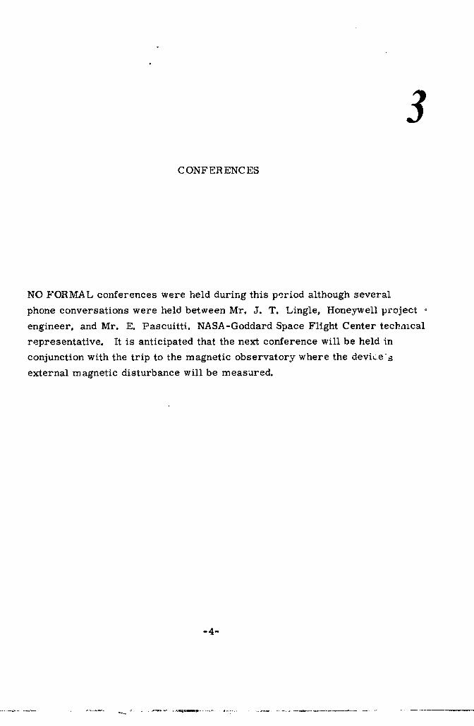
NO FORMAL conferences were held during this period although several
phone conversations were held between Mr. J. T. Lingle, Honeywell project
engineer, and Mr. E. PascuittL NASA-Goddard Space Flight Center tecbnlcal
representative. It is anticipated that the next conference will be held in
conjunction with the trip to the magnetic observatory where the devices
external magnetic disturbance will be measured.
-4-
1965013055-009

[
I 4
i PROJECT DETAILS
i A. PRELIMINARY MAGNETIC FIELD DISTURBANCE MEASUREMENTSi
PRELIMINARY MAGNETIC field measurements have been made on the coaxial
low input voltage Converter-Regulator, shown on Figure 1, to determine if
major deficiencies exist which must be corrected in the design before more
exacting tests are conducted at the magnetic observatory. These preliminary
tests were conducted by rotating the magnetic probe around various stations
of the low input voltage converter-regulator and measuring the difference between
magnetic fields when the converter is powering a 51 watt load and when it is
{ de-energized. By placing the probe 2-1/2 inches from the converter instead ofI 18 inches away, sufficient signal can be picked up in the earth's ambient field to
provide useful data. This data represents magnetic disturbance caused by the
operation of the iow input voltage converter-regulator and does not represent
disturbance due to any residual magnetic moments. Since the sensitivity of
the recording instrument was 0.05 milligauss and the measurements were
taken in a 500 milligauss ambient, the accuracy of the measurements was
less thandesired. However, the difference in magnetic disturbance could be
measured and plotted to provide significant data. These meast,xements showed
that the external magnetic disturbance around the coaxial converter section
was relatively low, but that the magnetic disturbance aroand the regulator
section was considerably higher. The high disturbance in the regulatort
i section was traced to the choke coil.
] -5-
1965013055-010

Figure 1 - COAXIAL LOW INPUT VOLTAGE CONVERTER-REGULATOR MODEL
-6-
1965013055-011

Figures 2, 3, and 4 show the plotof magnetic disturbancearound the low input
volta_.econverter-regulatorsectionat the coaxialinput, the center, and the
end joiningthe regulatorrespectively. Note (Figure 2) thatthe maximum mag=
neticdisturbancevariedbetween +0.8 and =0.8 milligaussas the probe was
rotated about the device. The magnetic field plot for the center of the converter
section on Figure 3 shows that the magnetic disturbance varied between +0.6
and -0.6 milligauss. Figure 4 shows that the magnetic field disturbance of the
converter end where it joins the regulator section varies between -0.5 and +0.4
milhgauss.
Examination of the eccentricity of the flux plot about the zero circle in Figures
2, 3, and 4 shows that they are all eccentric in the same direction. Because of
this it is highly probable that the magnetic disturbance measured is caused by
eccentricity in coaxial conductors which carry the high primary current,
This is discussed under B below and in Appendix A.
The magnetic field map at the regulator end of the device shown on Figure 5
has a higher level of disturbance between =0.9 and +2.4 milligauss. It was
also noted that a higher level of disturbance occurred around the center of the
regulator section in a direction parallel to the device axis. The magnetic
disturbance around the center of the regulator in this direction, shown in
Figure 6, vm-ies between 4 and 7.5 milligauss. It was discovered that the
choke coil was the primary cause of magnetic disturbance in the regulator
section. Separate magnetic field disturbance measurcments were made on
the choke coil.
-7-
1965013055-012

0 •
1 MILLIGAUSS
f ",,
/ \/ \
/ // ",, \
/ / \-1 \/ . \
I I / "
270- , : I I I! I 90.
\ / I I
\ _ "" " I/ /\ \ / /%. t"
\ "- j
/
\ /
CONVERTER-REGULATOROPEPATION- 180°MAGNETICPROBEORIENTATION
VIN -- 0.8 VDCRADIAL. TANGENTTO CONVERTER
Iiiii = 8:3,4 AMPERES SURFACE2.5 INCHESFROMTHE CONVERTERAXIS.
POUT = 51 WATTS LONGITUDINAL:
VOUT = 28 VOLTS AT INPUT TO CONVERI E_SECTION,
Figure 2 - MAGNETIC DISTURBANCE AROUND THE CONVERTER INPUT END
-8-
J
1965013055-013

1 AliCE
l
i80 •
CONVERTER-REGULATOROPERATION MAGNETICPROBE'ORIENTATION
VIN = 0.8 VDC RADIAl;: TANGENTTO CONVERTERSURFACE2.5 INCHESFROM
IIN = 83.4 AMPERES THE CO,_VERTERAXIS,
POUT = 51 WATTS LONGITUDINAL:
VOUT = 28 VOLTS AT CENTER OF CONVERTERSECTION.
Figure 3 - MAGNETIC DISTURBANCE AROUND THE CENTER OF THECONVERTER SECTION
_9 w J
1965013055-014

CONVERTER-REGULATOROPERATION MAGNETICPROBEORIENTATION
VIN = 0.8 VDC RADIAL: TANGENTTO CONVERTERSURFACE2.5 YNCHESIIN = 8,:3,4 AMPERES FROMTHE CONVERTERAXIS.
POUT = 51 WATTS LONGITUDINAL.'AT JUNCTIONBETWEENVOUT = 28 VOLTS CONVERTERSECTIONANDREGULATORSECTION
Figure 4 - MAGNETIC DISTURBANCE AROUND THE JUNCTION O.+_THE
CONVERTER AND REGULATOR SECTIONS
-10-
1965013055-015

1
0 o
11 1 MILLIGAUSS
i_ //_ "_\\\/__ 0 MILLIGAUSS
./ _
i I, , A/,, ; ,o.i / ', "L I/." //L- / -I MxiLLIGAUSS-"-T- /
180"
CONVERTER-REGULATOROPERATION MAGNETICPROBEORIENTATION
VIN -- 0.8 VDC RADIAL: TANGENTTO REGULATORSURFACE2.5 INCHES FROMIIN = 83.4 AMPERES THE REGULATORAXIS,
POUT = 51 WATTS LONGITUDINAL:AT OUTPUTEND OFREGULATOR.
VOUT = 28 VOLTS
Figure 5 MAGNETIC DISTURBANCE AROUND THE CONVERTER-
REGULATOR OUTPUT END
t
I-11-
i
1965013055-016

!6 MILLIGAUSS
//
/ q MILLIGAU,_S/ I "_
/ \/ / 2 MILLIGAUSS \
/ ... -.. \/ / ,, ,, \
/ ",
/ / 0 MILLIGA_JSS I/.
/I I J "_, 1270 °I I "i , 90°/I I\ _ , I !\ / I I\ \ / '
- /\ \ /\ ", / /
\ "-. i- /\ "- /
• /
CONVERTER-REGULATOROPERATION 180= MAGNETICPROBE ORIENTATION
VIN = 0.8 VDC RADIAL: TANGENTTO REGULATORSURFACE'2.5 INCHESFROMIIN = 83.4 AMPERES THE REGULATORAXIS.
POUT = 51 WATTS LONGITUDINAL: AT CENTEROFREGULATORSECTION.
VOUT = 28 VOLTS
Figure 6 - MAGNETIC DISTURBANCE AROUND THE CENTER OF THE
REGULATOR SECTION
-12-
4
1965013055-017

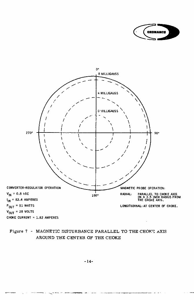
Figure 7 shows the magnetic field aromld the choke coil parallel to the
choke coil axis. Note that the field was relatively uniform at about 8.5
milligau3s. The flux in this direction is caused by incomplete magneto-
motive force cancellation in the two bucking sections which results in a
magnetic dipole. This effect can be caused by individual differences in
the _abrication and in the distributedair-gaps. A plot of flux at three
stations around the choke coil perpendicular to its axis (Figures 8, 9, and
10) shows that the field is relatively uniform and is lower at the ends. The
disturbance around the end where the wires exit, the center, and the other
end is 1.8 to 3.4, 3.3 to 4o 9, and -0.2 to +0.6 milligauss respectively.
Additional flux plots around other axis of the choke shown in Figures 11
and 12 indicate that the greatest disturbance is at the ends of the choke
as would be expected. Also the disturbance at the ends is relatively high
(20 milligauss). Some of the flux that leaks from the enclosed coils may
pass through the stainless steel screw used to hold the choke coil together.
Otherflux no doubt escapes along t:_e seams. When a 6 mil end cover was
! placed over each end, the disturbance was reduced as indicated in Figure 12.
It can be concluded from the preliminary magnetic field measurements that
the construction of the preliminary choke coil is not satisfactory. The follow-
ing action should be taken to improve this:
1. Use tighter fits between mating parts to eliminate distributed air-
gaps that cause the flux to fringe outside the mu-metal path.
2. Make the parts to closer tolerances to minimize distributed air
gaps and individual differences between the dual bucking sections.
3. Use overlapping joints at the seams to minimize flux leakage.
4. Place the completed choke in a shield can with a small non-
magnetic spacer between the choke and the can to maintain a
uniform spacing.
5. Annealthemu-m_a:_=._ toprovide maximum permeability.
-13-
] 9650 ] 3055-0 ] 8
0 o
8 MILLIGAUSS
//
/ 4 MILI.IGAUSS/
/ / \
/ / 0 MILLIGAUSS\. \
/ / ...-. - .., \
/ / / \ \I I / \
270" I I I \ Ii t 90=
I I \ / I\ \ / / /\ \ ,. / / /
\ / /\ \ / I\ \ I\ "_,, / I
\ /
_ s
CONVERTER-REGULA'fOROPERATION MAGNETICPROBEOPERATION:
VIN = 0,8 VDC I RADIAL: PARALLEL TO CHOKEAXIS180" ONA 2,5 INCH RADIUSFROM
IIN = 83,4 AMPERES THE CHOKEAXIS.
POUT = 51 WATTS LONGITUDINAL:AT CENTEROF CHOKE.
VOUT = 28 VOLTS
CHOKECURRENT= 1,82 AMPERES
Figure 7 - MAGNETIC DISTURBANCE PARALLEL TO THE CHOEE aXIS
AROUND THE CENTER OF THE CHOKE
-14-
1965013055-019

0 o
4 MILLIGAUSS
/ 2 MILLIGAUSS \
/4," ..---., ',',, ",I
270 ° I I " 9r.:
\ \ \"\\. ,,,,,. . ,/ / / /i\ .--" i,,/j i
CCNVE_T_R-REGULATOR OPERATION MAGNETIC PROBE ORIENTATION
VIN = 0.8 VDC 180° RADIAL: TANGENT TO CHOKECYLINDRICAL SURFACE
I,N_ = 8.",.4 AMPERES ON A 2.5 INCH RADIUSFROM THE CHOKE AXIS.P,,,,_ = 51 WATTSvuv LONGITUDINAl.: AT LEADWIRE END OF CHOKE.
VOUT = 28 VOLTS
CHOKE CURRENT = 1.82 AMPERES
Figure 8 - MAGNETIC DISTURBANCE PERPENDICULAR TO THE
CHOKE AXIS AROUND THE LEAD WIRE END
-15-
1965013055-020

0 o
MILLIGAUSSp D
/ "-',-
_ 2..MILLIGAUSS
\
/ / \\ \\O MiLLIGAUSS \,// / _ _ ,, \\
270"Jr_ I.... J --'F" ! --.--U--
CONVERTER-REGULAtOR OPERATION MAGNETIC PROBE ORIENTATION
VIN = 0.8 VDC 180° RADIAL" TANGENT TO CHOKE'CYLINDRICAL SURFACE
IIN = 8:3.4 AMPERES _N A 2.5 INCH RADIUS
POUT = 51 WATTS FROM THE CHOKE AXIS.
VOUT :: 28 VOLTS LONGITUDINAL: AT CENTER OF CHOKE.
CHOKECURRENT= 1.82 AMPERES
Figure 9 - MAGNETIC DISTURBANCE PERPENDICULAR TO THE CHOKE
AXIS AROUND THE CHOKE CENTER
-16-
i
1965013055-021

0 •
1 MILLIGAUS$
/ 0 MILLIGAUSS %_
/ \/ -1 MILLIGAUSS \
/ /--- -.. \/ / _ _
I I !270" I [ I 90"
!I '_ / I II \ / I I\ _-- ,.. / I\ \ / /\ \ / I
\ /CONVERTER-REGULATOROPERATION \ /\
VIN = 0.8 VDC "_ _.. "_ ..-," /
IIN = 83.4 AMPERES ""'" _-"
POUT= 51 WATTS
VOUT = 28 VOLTS 180 •CHOKECURRENT= 1.82 AMPERES
MAGNETICPROBEORIENTATION
RADIAL: TANGENTTO CHOKECYLINDRICALSURF/LCEONA 2.5 INCH RADIUSFROM THE CHOKEAXIS.
I.ONG|TUDINAL:AT END OF CHOKETHAT DOES NOT HAVELEADWIRES.
Figure 10 - MAGNETIC DISTURBANCE PERPENDICULAR TO THE CHOKE
AXIS AROUND THE END
-17-
1965013055-022

O"
-tlO MILLIGAUSS
/ MILUGAUSS _ \
/ / / / / / / i-"" --" -10..._",,..MILLIGAUSS _ _. _/
I / I i ,I"270" . I I i " I ' _ I ' ! I 90°
,, ,.... / ;' ),-,\ , , ,,, ,'/I
\ \ /\ "_ / /
CONVERTER'REGULATOR _ "" _'_OPERATION _ .... "" /
/VIN = 0.8 VDC _ /
IIN = 8_3,4 AMPERES "_ 1
POUT= 51 WATTS
VOUT = 28 VOLTS
CHOKECURRENT= 1.82 AMPERES180 °
MAGNETICPROBEORIENTATION
RADIAL: PERPENDICULARTO THE AXIS OF CHOKE,CHOKEIS ROIATED ABGUTAN AXIS PER-PENDICULARTO ITS OWN., PROBEISPARALLEL TC AXIS OF ROTATIONAT A2,5 INCH RADIUS FROM THE AXIS OFROTATION, PLANE OF LOCUSOF CHOKEAXIS PASSES THROUGHCENTER OF PROBE,
Figure II - MAGNETIC DISTURBANCE PARALLEL TO THE AXIS OF
ROTATION WHEN THE CHOKE IS ROTATED ABOUT A
PERPENDICULAR AXIS
-18-
1965013055-023

WITHOUT END CAPS
WITH 6 MIL MU-METAL END CAPS
_-20 MILLIGAUSS
.t .%J" %/
/ 0 MILLIGAUSS \
/-- _._ _" - _. \
/ ,.._<-,"'_'--'_,._ ,,, \
,,;fl.i ,
270" I [. I _ _ lIj_ I 90"
I _ I X i I /I I I
-',,_'-.._ �ill
CONVERTER-REGULATOR _'_L ,_, _ /OPERATION \ i
VIN= 0.8 VDC \ _ ,//
IIN = 83.4 AMPERES _. /
PO0¥ = 51 WATTS "- _ ---
VOUT = 28 VOLTS
CHOKE CURRENT = 1.82 AMPERES 180"
MAGNETIC PROBE ORIENTATION
RADIAL: PARALLEL TO LOCUS OF CHOKEAXIS PLANE. CHOKE IS ROTATEDABOUT AN AXIS PERPENglCULAR TOITS OWN. PROBE IS PERPENDICULARTO THE AXIS OF ROTATION.
Figure 12 - MAGNETIC DISTURBANCE PERPENDICULAR TO THE AXIS
OF ROTATION WHEN THE CHOKE IS ROTATED ABOUT A
PERPENDICULAR AXIS
-19-
1965013055-024

B. MAGNETIC DISTURBANCE AT AN EIGHTEEN INCH RADIUS
The distribution of the magnetic disturbance at a radius of 2.5 inches from
the axis of the Low Input Voltage Converter is shown on Figure 13. The
magnetic disturbance along the converter section is less than one milligauss
at this radius. It might b_ possible to extrapolate this data and calculate
the magnetic disturbance at a distance of 18 inches from the converter axis.
This may be somewhat difficult, however, because the exact cause of this
particular disturbance is not known and the accuracy of the readings may
not be sufficient to obtain significant data at a-distance of 18 inches. If this
magnetic disturbance is caused by eccentricity in the coaxial conductors,
then the magnetic disturbance would be a function of the following:
Where:
B = The magnetic disturbance flux density
R = The radius from the converter axis
X = The eccentricity
f = Denotes function.
This relationship show,= that the magnetic disturbance and the effect of the
eccentricity will decrease as the radius R increases. Thus, at a distance
18 inches out, the radius R will be greatly increased and hence the effect
of the small eccentricity will be decreased considerably. The magnetic
disturbance measurements made at a distance of 2.5 inches has provided
readings which are approximately 50 times the specification at a distance
of 18 inches. If the magnetic disturbance is caused by eccentricity in the
coaxial conductors, then it can be seen from this relationship that the effect
of this eccentricity wiU be much less at a distance of 18 inches. For example,
if the primary current into the low input voltage converter is 83.4 amperes
-20-
1965013055-025

1965013055-026

and if the construction were not coaxial, the field produced by a single
primary conductor at a distance of 2.5 inches would be 2.341 gauss.
However, coaxial construction is used, therefore each conductor produces
a field of approximately 2. 341 gauss and the two opposing fields cancel.
A small eccentricity prevents complete cancellation. Therefore, the
eccentricity is producing a net field of approximately 1 miliigauss because
of incomplete cancellation of fields on the order of 2. 658 gauss. This
represents a difference of one part in 2,341 as far as the cancellation effect
a_ a distance ol 2.5 inches is concerned. It can be seen from equation (1)
that if the measurements were made at a distance of 18 inches, then the
value of F_ would be increased by a factor of 7.2. This would result in a
very substantial decrease in the value of [1 _ _1 ][R R+X !
J
Calculations shown in Appendix A determine that a 0.000855 inch eccentricity
would produce the measured 0.8 milligauss field at a 2.5 inch radius. Using
this value for eccentricity, it is shown that the magnetic disturbance at 18
inches, due to the coaxial low input voltage converter section, should be about
0.89 gamma at 51 watts output. This is within the 2.0 gamma specification
requirement. This of course will have to be verified when more exacting tests
are conducted at the mag_.etic observatory.
C. CHOKE COIL EXTERNAL MAGNETIC DISTURBANCE
The magnetic disturbance around the choke coil is shown in Figure ] 4.
Notice that the disturbance around the choke coil in a direction perpendicular
to its axis is relatively low (under one milligauss at a distance of 2.5 inches).
However, the disturbance in a direction parallel to the axis of the choke is
quite high and uniform at approximately 8.5 milligauss at a distance of 2.5
inches from the choke axis. This shows that the main disturbance is caused
by a magnetic dipole effect. This disturbance may be caused by one of the
two bucking choke coil sections having a stronger magnetic dipole than the
other. It might also be caused by leakages through distributed air gaps at
the external seams.
-22-
1965013055-027

(_AIIICll
-23-
1965013055-028

AII|I
The magnetic field disturbance at an 18 inch distance from the choke coil has been
calculated in Appendix B. These calculations show that the magnetic disturbance
perpendicular to the choke axis is 2o 28 gamma or about 14% above the 2 gamma
specification requirement. The magnetic disturbance 18 inches from the choke
center along the choke axis is 4.56 gamma which is over twice the specification
requirement. These interpolated results show that the magnetic disturbance is
greater than desired. However, the results are reasonably close ior *.he first
attempt and this verifies that the basic design approach is correct. Because the
construction of the preliminary choke is unsatisfactory, it is necessary _o
improve this device to meet the requirements. The next choke should provide
satisfactory results and should be measured more accurately for magnetic
disturbance at the magnetic observatory.
D. CONSTRUCTION OF THE DUAL CHOKE COIL
Figure 15 shows a cross sectional view of the dual choke coil arranged with
two bucking halves. The ends and the center section of this choke coil were
fabricated from disks of 6 mil mu-metal. _11 of the disks were made the same
size to reduce the fabrication costs. The weight of the device could have been
decreased if the ends and center section were fabricated from different sized
disks staggered to provide a tapered radial cross section with decreased
thickness at _he periphery. This would maintain unit_orm cross-_ectiona I area
throughout the magnetic path. Although this would have decreased the weight,
it would have increased the fabrication costs considerably. Hence the
simpler approach, using only one disk size, was chosen on this preliminary
model. The central part of the core B1, B2 was fabricated by wrapping a
strip of 4 rail rnu-metal around a mandrel and building up a laminated
spiral cylinder. The two end bells, A1, A2, center disk C, and the two
center cores B1, B2_ form two spools around which two coils, D1, D2, are
wound upon two bobbins El, E2. Over this assembly, a two inch strip of 4
rail metal is wrapped to form the outer cylindrical case, F. Two end caps,
GI, G2, are placed over each end and a stainless steel screw H with a
stainless steel nut J is passed through a hole in the center of disks A1, A2,
-24-
1965013055-029

/°2D_" C
'-_ _ ,,./ir/-
?
Figure 15 - DUAL CHOKE COIL CONSTRUCTION
-25-
1965013055-030

center section C and center cores Bl, B2 to hold the entire assembly
together. Two air gaps, Kl aud K2 are located between the center cores
B1, B2 and the center disk C. The two coils, Dl and D2, are wound so that
the current passe_ through one in the clockwise direction and through the
other in the counterclockwise direction.
This produces the two bucking magnetic fields, so that the external magnetic
disturbance from each choke coil section opposes the other and tends to
cancel the magnetic disturbance in the space outside the choke coil. The
input and output leads of this choke coil exit through a coaxial cable to
minimize magnetic field disturbance.
This type of construction is advantageous because all of the flux which the
coils produce either passes through the iron or is enclosed by the iron
because the coils themselves are totally enclosed in the iron core. The
air gaps K1 and K2, are also totally enclosed within the iron core, A-B-C-F,
and hence the extremely high magnetic fields and fringing flux present at the
air gaps will not escape from the device because it is totally enclosed within
the iron sheath. Thus, these construction principles should provide a choke
coil having minimum external magnetic field disturbance. Howe,,er, the
measured magnetic field disturbance was larger than anticipated. This
high field disturbance is caused by the fringing of flux at the end bell seams,
possible escape of flux through the stainless steel screw, and unbalance
between bucking sections caused by either more _urns of wire on one coil than
on the other or by differences in tile distributed air gaps between the two
choke coil sections.
-26-
1965013055-031

i _aRl©|
t E. MAGNETIC DISTURBANCE FROM A CONVENTIONAL CHOKE COIL
Preliminary magnetic field measurements were made with a conventional
choke coil connected intc the low input voltage converter-regulator circuit.
This conventional (C_core type) choke coil produced a maglletic disturbance{ of 1.5 gauss at a radius of 2o 5 [nches from the center axis of its coil. By
comparison,the first dual section bucking choke coil produced a magnetic
I disturbance between 8.5 milligauss and 20 milligauss at the same radius and
i. 82 ampere load. Thus, the dual section choke coil with enclosed coils,
enclosed air gaps; and bucking external fields produced only 1% of the mag-netic disturb,_nce that a conventional choke coil produces. We anticipate _hat
the next dual section choke coil will have much lower external magnetic
disturbance because greater effort will be directed towards maintaining
_ uniformity and close tolerances during fabcication.
F. CHOKE COIL PROl_LEMS
Difficulties no_ed during tl_e fabrication and checkout of the dual section choke
i coil are as follows:
t 1. High eddy current loss was caused by:
The passage of flux through the end bell disk perpendicular!
to the direction of lamination.
The use of mu-metal which did not have any inter
lamminer insulation on it.
2. Somewhat loose fit of the mating parts which caused distributed
air gaps throughout the device and resulted in small air _aps at
the external seams which increased the external magnetic dis-
turbance.
- 2 7-
1965013055-032

3. The use of unannealed mu-metal (not a, nealed after cold working).
4. Lack of tapered or conical construction of the end bel]s and
center s_ction increased the choke coil weight.
Because of the above deficiencies, another choke coil will be fabricated. The
new choke coil will use mu-metal which has an inter-laminar insulation on each
side and the end bell laminations will be further subdivided +o reduce eddy
current losses and remove the tendency of the disk laminations to place a short
circuit on the enclosed magnetic flux. These changes will be made before the
device is tested at the magnetic observatory. The changes are discussed in
greater deta:l below.
G. EDDY CURRENT EFF_ZCTS AT THE CHOKE COIL END BELLS
Examination of the choke coil construction and magnetic paths shows that the
highest eddy current concentration will occur in the end bell disks because the
direction of flux is perpendicular to the laminations. This is shown in
Figures 15 and 16. Since the eddy currents generated are also perpendicular
to the flux lines, the laminations do not break up the current paths and
circular eddy currents can flow around the disk as indicated in Figure 16.
The alternating flux induces voltages around circular paths in the disk
lamir '" ,n proportional to the amount of flux enclosed in a given concentric
circus:, path. The maximum induced voltage (Ep) occurs around the circlethat encloses the total flux and this voltage is equal to the voltage per turn
impressed across the cheke coil winding. The conductive path thvough the
disk lamination thus places a shorted turn on the choke coil. The total
eddy current flowing through the disk is then:
R
P E(x) dxIe = R(x)
o
-28-
1965013055-033

1"
EPE2
Figure 16 - CHOKE END BELL EDDY CURRENTS
-29-
1965013055-034

"Where:
I = Total eddy currente
R(x) = Resistance of loop at radius
E(x) = Voltage at corresponding radius
Rp = Radius at the periphery
The resistance is determined by the path length, the lamination resistivity,
and the incremental area per path. Since the end bell is not laminated in a
direction that will break up the eddy current paths, lamination of the
materi_t in a plana perpendicular to the direction of flux flow is ineffective.
The effective thickness of the material can be considered to be the average
depth of perpendicular flux penetration into the end bell. The eddy current
loss (Pe) is:
R
f P E(x)2
P = dx
e R(x)O
H. REDUCTION OF EDDY CURR._.NT LOSSES
Figure 17 shows methods which can be used to break up the end bell eddy
current paths thereby reducing the eddy current losses there.
Figure 17a shows that complete concentric circular psths exist in the
undivided disk. Flux passes through some of the disks, comprising the end
be!l, perpendicular to the disk surface. The complete circular paths
linking the greatest change in this perpendicular flux then have the highest
voltage induced in them. If the area enclosed by the path is decreased, the
voltage induced in that path i.-. also decreased. One may observe that for
the same path widtb, the resistance of the decreased path will also be less.
-30-
1965013055-035

-31,.
1965013055-036

The significant point is, however, that by increasing the total length of the
insulated boundames enclosing a specific change in flux, the voltage to
resistance ratio is decreased and the eddy current power !oss is also
decreased.
Figure 17 further illustrates the reduction in eddy current power loss.
Although the disc indicated in Figure 17b is divided into six sections, the
following approach to eddy current power loss , _1 assume n sections to
provide a more general discussion. The resistance for the path around the
periphery of the uncut disc (Figure 17) is equal to
2_rR = 0 -- = 0 - K2TTr
A A
Where
r = radius to path
0 = resistivity
A = cross sectional area of the conducting path.
By comparison, the resistance arou,,d _be periphery of each section of
Figure 17 is equal to
R' = K (2+ 2-3-_)rn
assuming the same path cross sectional area. The voltage (E')induced in
each sectiou of th_ cut disc will be 1/n of the voltage (E) induced in the
totaluncut disc. Thus the power loss in the path of tl_eperiphery of
each sectipn will be equal to
(E/n)2pt _-n
K (2 +2_) rn
-32-
1965013055-037

The sum of the power loss at the periphery for all n sections will thus be
n (E/n)2pn = np, =
n
K(2+2_)rn
The corresponding power loss in the uncut disk will be equal to
E 2
K2 _r
Taking the ratio of these powers
E 2P-P-- = "_-'_'r-- = _2n + 27t _ n + 1p, 2_ r
n (E/n)2
K (2 + _-_ )r
indicates a substantied reduction in the loss with the sectioned disc.
A like result will be obtained if additional and related current paths at
incremental displacements from the center are considered for the respective
configurations,
Thus the power loss in the sectioned disc should be substantially less than
that of the non-sectioned disc. A rigorous analysis of the eddy currents of
a system becomes rather involved but it is felt that the preceding discussion
is sufficient to indicate that segmenting the discs will substantially reduce
the eddy current power loss in the end bell.
-33-
1965013055-038

ANG|
Another method of reducing-the eddy current losses is the use of involute
spiral laminations as shown on Figure 17c. This would result in a much greater
eddy current reduction because the eddy paths are much more finelydivided.
However, this type of end bell is more difficultto construct and requires a
certain geometrical relationship between the center hole diameter, the outside
diameter, and the lamination thickness. Honeywell has fabricated devices
from laminations of this type and has found that the spiral lamination should
not extend more than 180_.
Another way to diminish the end bell eddy current loss is to recess the
cylindrical core section part way into the end bell as shown on Figure 17.
This arrangement will allow some of the flux to exit through the segmented
donut laminations (B) parallel to the direction of lamination. This reduces
the flux density of flux flowing perpendicularly intothe segmented end disks
(C). Itis necessary to segment the d ,nutlaminations (B) to prevent a shorted
turn on the choke coil.
Tests on the preliminary choke coil model have estabhshed that excessive
eddy current losses were caused by the lack of an insulated coating between
the laminations. Also, the end bells were not laminated in the proper
direction to minimize eddy current loss.
These difficiencies will be corrected by the fabrication of another choke coil
utilizing insulated laminations and design changes discussed above.
I. DEPERMING COIL
The deperming coil for use in magnetic field disturbance tests at the observatory
has been designed and fabricated. This coil is approximately 4. 1 inches in
diameter and 41 inches long. It contains 740 turns of No. 16 wire and will be
operated from a variac. Magnetic field tests have shown that the deperming
cml produces a field twe diameters in from each end which has less than 3%
variation throughout the volume. A current of 2.69 amperes is required to
produce a 25 gauss field.
-34-
1965013055-039

5CONCLUSIONS
THE DATA obtained from the preliminary magnetic i'ield disturbance tests
on the low input voltage converter-regulator indicate that the external magnetic
disturbance generated by the low input voltage converter _ction i,_ satisfactory.
Although the measurements obtained in the earth's high ambient magnetic field
do not have the desired accuracy, they have provided valuable information. If
the data taken at 2.5 inches from the axis of the co, erter is interrJolated
out to 18 inches, the external magnetic disturbanc • _ auc_ed by _h_ cn_ial low
inpu_ voltage converter section is 0. 892 gamma ; :h is considerably less
than the 2 gamma specffication requirement. Thut it ._an be c_,ncluded that\
the coaxial construction of the low input voltage converter ,'_,_ 'or results --
in a substantial decrease in the external magnetic field distu_-bance. Hence,
this design approach is very cl-e-s'_a_q_To1_'I6%-i_p'dt voltage converter-regulatOrs
which have a requirement of minimum external magnetic field disturbance.
Besides minimizing the external magnetic field disturbance, coaxial construction
also minimizes the inductance of the converter primary section and this
reduces the generation of "*vow.age spikes at the power transistor collector
emitter junctions. The reduction of voltage spikes by coaxial construction
greatly decreases the switching losses in the oscillator power transistors
because the instantanious voltage current product is reduced du_ing switching.
This a11ows efficient operation at higher operating frequencies where weight
reduction can be achieved. Thus, all performance tests and magnetic disturbance
-35-
1965013055-040

AgICI!
tests have indicated that the coaxial constructicn has resulted in significant
improvements in the device performance and itappears that a very satisfactory
converter can be fabricated using this technique.
The preliminary external magn ,tic field disturbance measurements have
shown that the dual section bucking choke coil has a higher magnetic field
disturbance than originally estimated.
Tests have shown that the external magnetic field disturbance produced by
the first dual section choke coil was about 1% of that produced by a conventional
choke coil. Calculations indicated that the magnetic disturbance due to the
dual section choke coil would be about 4.56 gamma for the worst case at an
18 inch distance. This is more than twice the 2 gamma specification require-
ment.
Performance tests have also shown that this choke coil has excessive eddy
current losses. Thus, the preliminary tests have shown that the design of
the dual section bucking choke coil must be improved. This will be done by
redesigning the end bell disk laminations and the center disk laminations
to provide lamination in the direction parallel to flux flow and thereby reduce
their eddy current losses. Also, metal with inter laminar insulation will be
used in the construction of this device to minimize the eddy current losses
and provide a choke coil of having satisfau_ory efficiency.
The tests conducted during this past quarter have shown that the low input
voltage converter section of this device appears to be satisfactory from a
performance and a magnetic field disturbance standpoint. These tests have
also shown that the dual section choke coil has certain design deficiencies
which must be corrected during the next quarter. The procurement of
satisfactory insulated magnetic material has caused some delay in the
fabrication of the new choke coil. Action is now being taken to redesign
this choke coil and correct the deficiencies so that satisfactory perfcrmance
tests can be made at the magnetic observatory.
-36-
1965013055-041

I _ANC|
The preliminary magnetic fieId measurements have indicated that although
the converter section appears satisfactory, the chore coil requires further
work. It can be concluded that the basic design approach for this choke coil
does minimize magnetic disturbance; however, certain improvements must
be made in the fabrication procedure to obtain the benefits that this approach
can provide. These tests have pinpointed the design deficiencies and the
information obtained will be useful in achieving the design goals with the
deliverable model.
These conclusions are based upon magnetic disturbances calculated from
preliminary measurements- in the earth's strong ambient field. More accurate
tests to be conducted at the Magnetic Observatory are necessary to verify that
the preliminary results are accurate and to establish thedefinitely magnetic
disturbance level.
i
i!
i!
-37-
1965013055-042

PROt_[4AM FOR THE NEXT QUARTER
DURING THE next quarter, the new choke coil will be fabricated in order to
correct the deficiencies noted in the present choke coil design. This new
choke coil will then be inserted in the coaxial low input voltage converter-
regulator and some preliminary magnetic disturbance checks will be made.
After this, magnetic disturbance tests will be scheduled at the magnetic
observatory for the low input voltage converter-regulator.
During the next quarter, further effort will be directed toward weight reduc-
tion. The use of electroplated magnesium for some of the parts inside the
coaxial converter section will be considered. Also, some of the structural
components in the regulator section will be examined to determine where
weight can be reduced further. The use of three supporting rods in place
of two in the regulator section will be considered '_o provide greater rigidity
for the mounting of regulator components.
During the next interval, the final deliverable model will be fabricated and
performance tests, environmental tests, and battery charging tests will be
performed on this unit.
-38-
1965013055-043

AIMCII
APPENDIX A
CALCULATION OF EXTERNAL MAGNETIC DISTURBANCE AT AN
!8 INCH RADIUS FROM THE COAXIAL LOW INPUT VOLTAGE CON-
VERTER SECTION
The magnetic disturbance has been measured at a radius of 2. 5 inches from
the low input voltage converter section, It will be assumed that the measured
magnetic disturbance is caused by eccentricity in the coaxial primary conductors
and the magnitude of eccentricity required to produce the measu_._d £ieid witl be
calculated. After this has been done, the eccentricity obtained will be used to
calculate the magnetic disturbance at an 18 inch radius. To perform these
calculations, the following conditions are given:
Coaxial Converter Length = 25 cm
Magnetic Disturbance at 2o5 inch or (6. 35 cm) radius at !ongitudinal
center = 0o 8 milligauss
Primary current = 83° 4 amperes
Determine magnetic field disturbance at a radius of 18 inches (or
45. 7 Cm)o
The magnetic field intensity around a finite straight wire is given by:
Po IB - (cos e 1 - cos 02) (1)
4ha
where the symbols are defined by the following construction:
B is in webers/m 2
I is in amperes
a is in meters
-39-
1965013055-044

N_4NC|
_o -_ '4 x 10 -7 webersAmpere reeler
91 = angle subtended by line from one end of converter to point
and line t},rough'.¢_nvei_t_'r ,axis (_ee I_i_llr_ 1,q).
62 = angle subtended by line from opposite end of converted topoint and line _h'l_Otlgh: (_,_nvei_t_,,_xi___' :
For a distance of 6.35 cm radial from center of converter sectio,], tan e l =
6. 35 crn = 0.5n8
12. 5 cm
01 = 26. 93 _
02 = ]80 ° -26.93 =
= 153. 07 °
cos 01 = 0.892
cos 02 = -0.892
Then B = 4r x 10 -7 x 83.4 [ 0.892 - (-0.892)]47r (0. 0635)
-7= 83.4 x 10 (1. 784)
O. 0R35
= 13. 13 x 10 -5 (1. 784)
-- 23.41 x 10 -5 webers/m 2
= 23.41 x 10 -1 gauss
= 2.341 gauss.
-40-
1965013055-045

X
Figure 18 - GEOMETRIC CONSTRUCTION OF COAXIAL CONDUCTORS
WITH SMALL ECCENTRICITY
, -41-
1965013055-046

Thus, the fielddue to current through one ofthe coaxialconductors is 2.341 gauss
at a distanceof 2.5 inches from the converter axis. The other conductor will
produce an equal opposing field. However, a small eccentricitywillresultin
incomplete magnetic fieldcancellationand willproduce a net fieldof 0.8 miUi
gauss. Itis now desirableto calculatethiseccentricity.To simplifythe
calculations,itwillbe assumed thatthe value of 01 and 92 do not change dueto the eccentricity.This willprovide an accurate approximation because
changes in the cosinefunctionfor small increments at thisangle are practically
iasignificant.
The equation then becomes:
B a - B b = 83.4 x 10⁻⁷ (_I a+l x) (cos 81 - cos 82)
- 83. 4 xB(a_b) x 10-7 a(a+x) 2 Cos 01
= 83. 4 x 10 -7 xa (a_Vx) (1.784).
It was previously determined that 83.4 x 10 -7 (1. 784) produced field ofa
2. 341 gauss, therefore the equation can be written as
= 2. 341 XBa_ b gauss a + x
-3Measurements have shown thatBa, b = 0.8 x 10 gauss. Substitutingthisvaluewe can solve for the eccentricity(x).
10-3 x0.8 x = 2.341 . 0.0635+x
1 - O.8 x 10-3 O.8 x 10-3 (0.0635)X =
2.341 2.34i
-42-
1965013055-047

IUJLIOC|
x (0. 999658) = O. 21700128 x 10 -4
= O. 21707x10 -4 Meter
-3-- O. 8546xi0 Inch.
Using this value of eccentricity the magnetic field disturbance at a distance
18 inches from the converter axis can be estimated by:
Bp B c - B d
Where:
B = Magnetic Field Disturbance at Point P.P
B c = Magnetic Field Duo to Current in one Conductor at 45.7 cm Distance
Bd = Magnetic Field Due to Opposing Current in the other Conductor at(45.7 cm + x) Distance.
_ I (Cos 83 -Cos @4)B c -
IBd = a-_x (Cos {)5 " Cos 06)
Cos 83 = -Cos 84
_ 12.5Cot 83 45. 7
= 0. 2735229
Cos 85 = -Cos e 6
-43-
1965013055-048

?
12.5 :
Cot % = 45.7+x\
x = O. 21707 x i0-4 Meter?
_ Since Cot 03 = O, 2735229 • :
83 ffi 74.7.025 ° '
12.__CotO 5 = _7 = 0.2735100 --
-_ _O5 = 74. 7032" .. : _'4_
9 3 _ :: Cos :,= .26.383096 "' :. : - ._ ., :_.
" Cos 05 -= O; 6381918 - "_
(cos 03 - Cos o41 = o. 52766192
(Cos e5 --Cos-06_)_ =. 0. 52763836 : ..'J "_j. r
Then __ _ ,. ;
_C -_t83"4X!0-7 )0. '57 _ "-(0" _52 _"66192'' _" _
= 44. 007004128 x 10] 7 ")
.i
• = 96. 2954l x 10 a7
Andc ""L'*
-. Bd: = (0. 52763836) :_ : ,
" 2;'
:," " . . ,. , ' " " ._ ._ _._. . c",_._ :.,. ,;:t:... _ ,. ._,: ,_,"._,_,.:.<_4:.= .'_.,' ,;.,.',. '_ ,'" ,._'-_" ,, .,..._."_.
'19650 "1:3055-049

r
_- OmmAamu:
= 44. 00504256 x 10 -7
!_[_ O.457022
_1: = 96.28649 x 10 -7
" [/ - " • • - =
Bp = B c - B d -
• (96. 29541 - 96. 28649) x 10 -7
"U: : - " ";7 :" ', - = 0. 000892 x 10
=-. •- _;:8.9.2 X 10-i! 0 Webers/(Meter) 2 '_
..... = 8; 92 Gauss. "
. = O:802-GammaBp
•s :- : :_ :: ©
:-":_ If we neglect the _effect of the eccentricityon the Cos O
:[_ = Bc.B d i83.4 x i0-7)-(83.4 x 10⁻⁷) (Cos O3 Cos 041 :. - = 0. 4570000 • 0. 4570217; -
_- = 0. 003665 x 0. 52766 x 1O"7 = 0. 00457 _ 10"7webers/meter 2 "
[i_ = 0. 457_: Gamma :_u
Thus it can be seen that the interpolated magnetic d.[sturbgnce at a.'_ 18;inch
,: _.note that _e values for the Cos O-have asignifiCant effect upon the interpp!ated: "
'_. : results. Therefore for. more accurate interpoiation it =wofild be .necessary to '
consider this in the determination of eccentricit_ (x). These calculations and
:: -45- '
2" u _ /
1965013055-050

mS|
and assumptions establish that the magnetic field disturbance is within the
specification limits {as far as the coaxial col_verter section is concerned}.
Consequently, it is now desirable to conduct more accurate tests at the
magnetic observatory to accurately determine the magnetic disturbance at
the 18 inch distance. It will be necessary to improve the choke coil before
this is accomplished. It must be noted that the above calculated results are
based upon inagnetic field measurements in the earth's strong ambient field.
Since the measured disturbance is much less than the earthts field _he
accuracy of these ,neasurements cannot be reliably established. Therefore
more accurate measurements may establish results which are considerably
different from these preliminary calculations.
-46-
] 9650 ] 3055-05 ]
AIIICB
APPENDIX B
CALCULATION OF THE EXTERNAL MAGNETIC FIELD DISTURBANCE
EIGHTEEN INCHES FROM THE DUAL SECTION CHOKE.
The external magnetic disturbance measured at a distance of 2. 5 inches from
the choke axis will be used to calculate the inherent magnetic moment of the
choke. It will be assumed that a single magnetic dipole produces this magnetic
moment. The external magnetic field due to this magnetic moment will then
be calculated for two positions at an 18 inch distance from the choke center.
The calculations follow:
Examination of Figure 14 shows that the external magnetic field parallel to
the choke axis at a distance of 2. 5 inches (0. 0635 meter) is 8.5 milligauss.
! It will be assumed that this field is caused by a single magnetic dipole of
moment M. The magnitude of this magnetic moment can be found from the
following _quation:
B=_° ( 3MC°s 0-'*'4_- r4 r - --_1 --_)M (1)r
Where the geometrical construction is as shown on page A-8 ol Progress
Report #1 for this contract (3899) and the symbols are as follows:
B = fmx density in webers/(meter) 2
= Permeability of space = 4_r x 10 -7 webersampere meter
M = Magnetic moment vector of dipole
r = Distance from center of the dipole to the point.
-47-
1965013055-052

e= Angle betwcen M and r
P1 = a point on the choke axis at a distance
P3 = a point on the perpendicular with the choke axis that passes
through the c_oke center and is at a distance r from it.
For PlJ0 = o° and for P3 _O = 90%
Our preliminary measurements at a point P3' showed that for r = 0. 0635 meter
and O = 90° that B = 8. 5 x 10 -3 gauss parallel to the choke axis.
or B = 8.5 x 10 -7 webers/(meter) 2 at P3' substituting in equation 1 gi_es.
8.5 x 10 -7 - 4_ x 10 -7 F3M Cos 90 _ (0. 0635) /_ 90 ° 1 -_1
47r L(0_ 0635) 4 (0. 0635) 3 jThls reduces to
8.5 = - M
(0. 0635) 3
-M = 8.5 (0. 0635) 3
-M = 21. 764 x 10 -4 ampere (meters) 2
M has a direction coinciding with the chok o axis and is oriented 180 ° from
the fiux measured at P3"
We can again substitute in equation (1) to find the disturbance at 0. 457 meters
from the choke at P3"
-48-
1965013055-053

ANOIE
L JB - 47r x 10 -7 3 (-21.764x 10 -4) Cos 91Y' (.457) 90° - (-21.764 x 10 -4)4_ CO.457)4 CO.457)3
:1o7[_,21764xlo4],oB = 2. 2804 x 10 -9 webers/(meter) 2
-5= 2.2804 x 10 gaus_
= 2. 2804 gamma at P3
Thus tt_e magnetic disturbance on a perpendicular from the choke coil axis
at a distance of 18 inches from the choke center is 2. 2804 gamma. This
exceeds the 2 gamma s _ecification requirement by about 14%. The magnetic
disturbance along the choke axis will be much higher however and can be
calculated at 0. 457 meter distance as follows:
Substituting va]ues for P1 in equation (1B) gives:
B 4_x i0-7 [3(-21.764x I0-4}cos o°- (0.457) L0 _ (-21. 764 x 10 -4)
4_ L (0. 457) 4 (0. 457) 3 J
B = 10 -7 [(-21,764 x 10 -4 ) (3 - 1_
L (0. 457) 3
s = 10-7 [ 2(-21.764x 10⁻⁴)]L
B = 4. 561 x 10 -9 webers/(meter) 2
= 4.561 x 10 -5 gauss
B = 4. 561 gamma at P1
-49-
1965013055-054

This is over twice the specification requirement and indicates that improvements
should be made. Although these calculations show that the choke coil external
magnetic field disturbance is too high the values obtained are reasonably close
to the specification requirements. This indicates that the design approach is
a step in the right direction and that further improvements discussed in the
text should result in the fabrication of a satisfactory choke coil.
-50-
1965013055-055
![OWNER’S MANUAL ENGLISH...• Manual choke: Place the choke lever/rod [1] in the CHOKE position when starting a cold engine. Move the choke lever/rod to the OFF position as soon as](https://img.pdfslide.us/doc/110x75/60a7b2c65c7ba02e7841f517/owneras-manual-english-a-manual-choke-place-the-choke-leverrod-1-in.jpg)