Embed Size (px)
Citation preview

~HONDA "f SHOP MANUAL
IMPORTANT SAFETY NOTICE -----____,
lndicstes s strong possibility of severe persona/ injury or desth if instructions are not followed.
CAUTION: lndicstes a possibility of equipment damage if instructions are not followed.
NOTE: Gives helpful information.
Detailed descriptions of standard workshop procedures, safety pr.inciples and service operations are not included. lt is important to note that this manual contains some warnings and cautions against some specifie service methods which could cause PERSONA.L INJURY to service personnel or could damage a vehicle or render it unsafe. Please understand th at th ose warnings cou Id not cover ali conceivable ways in which service, whether or not recommended by Honda, might be done or of the possibly hazardous consequences of each conceivable way, nor could Honda investi gate ali such ways. Anyone using service procedures or tools, whether or not recommended by Honda, must satisfy himself thoroughly that neither persona! safety nor vehicle safety will be jeopardized by the service methods or tools selected.
TYPE CODE
• Throughout this ma nuai, the following addreviations are used to identify individuel modal.
CODE AREA TYPE
ED EUROPEAN DIRECT SALES
E U.K.
F FRANCE
sw SWITZERLAND
IIG GERMANY (TYPE Ill

VARADERO 125 VALVE CLEARANCES
Remove fuel tank 2-8
Remove front inner fairing 2-6
Drain coolant 6-5
Remove radiator 6-8
Remove ai.r cleaner housing 6-4
Remove cylinder head covers 9-5
CHECK CLEARANCES 3-8
Refit cylinder head covers 9-25
Refit air cleaner housing 6-4
Refit radiator 6-12
Refit front inner fairing 2-6
Refit fuel tank 2-8
Refill coolant and bleed system 6-6

HOW TO USE THIS MANUAL
This service manual describes the service procedures for the Xl125V.
Follow the Maintenance Schedule (Section 3) recommandations to ens ure th at the vehicle is in peak operating condition.
Performing the first scheduled maintenance is very important. ft compensates for the initial wear that occurs during the break-in period.
Sections 1 and 3 apply to the whole motorcycle. Section 2 illustrates procedures for removal/ installation of components that may be required to perform service described in the following sections. Sections 4 through 20 describe parts of the motorcycle, grouped according to location.
Find the section you want on this page, then turn to the table of contents on the first page of the section.
Most sections start with an assembly or system illustration, service information and troubleshooting for the section. The subsequent pages give detailed procedure.
If you don't know the source of the trouble, go to section 21 Troubleshooting.
ALL INFORMATION, ILLUSTRATIONS, DIREC
TIONS AND SPECIFICATIONS INCLUDED IN THIS
PUBLICATION ARE BASED ON THE LATEST
PRODUCT INFORMATION AVAILABLE AT THE
TIME OF APPROVAL FOR PRINTING. HONDA
MO TOR CO., L TD. RESERVES THE RIGHT TO
MAKE CHANGES AT ANY TIME WITHOUT
NOTICE AND WITHOUT INCURRING ANY OBLIG
ATION WHATEVER. NO PART OF THIS PUBLICA
TION MAY BE REPRODUCED WITHOUT WRmEN
PERMISSION. THIS MANUAL IS WRITTEN FOR
PERSONS WHO HAVE ACOUIRED BASIC KNOWL
EDGE OF MAINTENANCE ON HONDA MOTORCY
CLES, MOTOR SCOOTERS OR ATVS.
HONDA MOTOR CO., L TD.
SERVICE PUBLICATION OFFICE
z ct. a: .... w > a: c c z ct w z 5 z w
CONTENTS
GENERAL INFORMATION
FRAME�BODY PANELS/EXHAUST SYSTE
MAIN TENANCE
LUBRICATION SYSTEM
FUEL SYSTEM
COOLING SYSTEM
ENGINE REMOVAL/INSTALLATION
CLUTCH/GEARSHIFT LINKAGE
CYLINDER HEAD/VALVE
BRAKE SYSTEM
CHARGING SYSTEM/ ALTERNA TOR
IGNITION SYSTEM
ELECTRIC STARTER/ STARTER CLUTCH
LIGHT /METER/SWITCHES
WIRING DIAGRAM
TROUBLESHOOTING
INDEX
.. -Ill

SVMBOLS
The symbols used throughout this manual show specifie service procedures. If supplementary information is required
pertaining to these symbols, it wou Id be explained specifically in the text without the use of the symbols .
., Replace the part(s) with new one(s) before assembly.
, Use recommended engine oil, unless otherwise specified.
, Use molybdenum oil solution (mixture of the engine oil and molybdenum grease in a ratio
of 1:1).
-� Use multi-purpose grease (lithium based multi-purpose grease NLGI #2 or equivalent).
Use molybdenum disulfide grease (containing more than 3% molybdenum disulfide, NLGI
� #2 or equivalent). Example: Molykote• BR-2 plus manufactured by Dow corning, U.S.A.
Multi-purpose M-2 manufactured by Mitsubishi Oil, Japan
Use molybdenum disulfide paste (containing more than 40% molybdenum disulfide, NLGI
#2 or equivalent).
� Example: Molykote• G-n Paste manufactured by Dow corning, U.S.A.
Honda Moly 60 (U.S.A. only) Rocol ASP manufactured by Rocol Limited, U.K. Rocol Paste manufactured by Sumico Lubricant, Japan
� Use silicone grease.
0,,,191 Apply a locking agent. Use a middle strength locking agent unless otherwise specified.
-''� Apply sealant.
... Use DOT 4 brake fluid. Use the recommended brake fluid unless otherwise specified .
... Use Fork or Suspension Fluid.

GENERAL SAFETY 1-1
SERVICE RULES 1-2
MODEL IDENTIFICATION 1-3
SPECIFICATIONS 1-4
TORQUE VALUES 1-13
GENERAL SAFETY
CARBON MONOXIDE
If the engine must be running to do some work, make sure the area is weil ventilated. Never run the engine in an enclosed area.
The exhaust contains poisonous carbon monoxide gas that may cause Joss of consciousness and may /ead to death.
Run the engine in an open area or with an exhaust evacuation system in an enclosed area.
GASOLINE
Work in a weil ventilated area. Keep cigarettes, flames or sparks away from the work area or where gasoline is stored.
Gaso/ine is extremely flammable and is explosive under certain conditions. KEEP OUT OF REA CH OF CH/LOREN.
HOT COMPONENTS
tliMM'Mi Engine and exhaust system parts become very hot and remain hot for some time after the engine is run. Wear insu/ated gloves or wait until the engine and exhaust system have cooled before handling these parts.
1. GENERAL INFORMATION
TOOLS 1-16
LUBRICATION & SEAL POINTS 1-18
CABLE & HARNESS ROUTING 1-20
EMISSION CONTROL SYSTEMS 1-27
USED ENGINE Oll
Used engine oil may cause skin cancer if repeatedly left in contact with t h e skin for prolonged periods. Although this is unlike/y unless you handle used oit on a dai/y basis, it is sti/1 advisable to thoroughly wash your hands with soap and water as soon as possible after handling used oit. KEEP OUT OF REACH OF CH/LOREN.
BRAKE FLUID
CAUTION:
Spi/ling fluid on painted, plastic or rubber parts will damage them. Place a clean shop towel over these parts whenever the system is serviced. KEEP OUT OF REA CH OF CH/LOREN.
BA TTERY HYDROGEN & ELECTROLYTE
• The battery gives off explosive gases; keep sparks, flames and cigarettes away. Provide adequate ventilation when charging or using the battery in an enclosed space.
• The battery contains su/furie acid (electrolyte). Contact with skin or eyes may cause severe burns. Wear protective clothing and a face shield. - If electrolyte gets on your skin, flush with water. - If electrolyte gets in your eyes, flush with water for
at /east 15 minutes and cal/ a physician immediate/y. • Electrolyte is poisonous.
- If swallowed, drink large quantifies of water or milk and follow with milk of magnesia or vegetab/e oit and cal/ a physician. KEEP OUT OF REACH OF CH/LOREN.
1-1
..

GENERAL INFORMATION
SERVICE RULES
1. Use genuine HONDA or HONDA-recommended parts and lubricants or their equivalents. Parts that do not meet
HONDA's design specifications may damage the motorcycle. 2. Use the special tools designed for this product. 3. Use only metric tools when servicing this motorcycle. Metric bolts, nuts and screws are not interchangeable with
English fasteners. The use of incorrect tools and fasteners may damage the motorcycle. 4. lnstall new gaskets, 0-rings, cotter pins, lock plates, etc. when reassembling. 5. When tightening a series of bolts or nuts, begin with the larger-diameter of inner bolts first, and tighten to the speci·,
fied torque diagonally, in incrementai steps unless a particular sequence is specified. 6. Clean parts in cleaning solvent upon disassembly. Lubricate any sliding surfaces before reassembly. 7. After assembly, check ali parts for proper installation and operation. 8. Route ali electrical wires as show on pages 1- through 1- , Cable and Harness Routing.
1-2
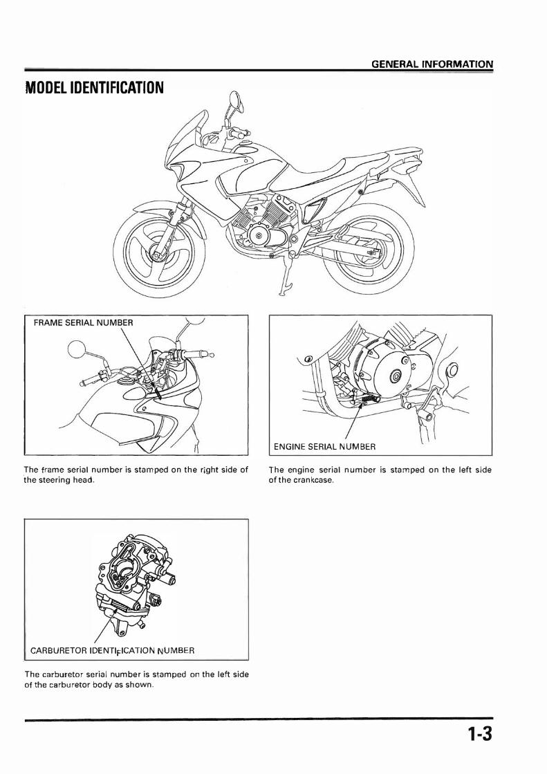
MODEL IDENTIFICATION
The frame seriai number is stamped on the right side of 'the steering head.
CARBURETOR IDENTIFICATION NUMBER
The carburetor seriai number is stamped on the left side
of the carburetor body as shown.
GENERAL INFORMATION
ENGINE SERIAL NUMBER
The engine seriai number is stamped on the left side of the crankcase.
1-3

GENERAL INFORMATION
SPECIFICATIONS , GENERAL
ITEM SPECIFICATIONS
DIMENSIONS Overall length 2,150 mm (84.6 in) Overall width 850 mm (33.5 in) Overall height 1,250 mm (4.9.2 in) Wheelbase 1,450 mm (57.1 in) Seat height 802 mm (31.6 in) Ground clearance 190 mm (7 .5 in) Dry weight 154 kg (339.51bs) Cu rb weight 167 kg (368.2 lbs) Maximum weight capacity 180 kg (396.8 lbs)
FRAME Frame type Double cradle Front suspension Telescopic fork Front wheel travel 132 mm (5.2 in) Rear suspension Swingarm Rear wheel travel 150 mm (5.9 in) Front tire size 1 00/90-18 56P Rear tire size 130/80-17 65P Front tire brand BRIDGESTONE, PIRELLI Rear tire brand BRIDGESTONE, PIRELLI Front brake Hydraulic single dise Rear brake Hydraulic single dise Caster angle 28°00' Trail length 97 mm (3.8 in) Fuel tank capacity 17.5 liter (4.62 US gal, 3.85 lmp gal) Fuel tank reserve capacity 2.0 liter (0.53 US gal, 0.44 lmp gal)
ENGINE Bore and stroke 42.0 x 45.0 mm (1.65 x 1.77 in) Displacement 125 cm• (7.6 cu in) Compression ratio 11.8: 1 Valve train Silent multi-link chain driven SOHC with rocker arms lntake valve opens 6° BTDC
closes 24° ABDC Exhaust valve opens 31° BBDC
closes go ATDC Lubrication system Forced pressure (dry sump) Oil pump type Trochoid Cooling system Liquid cooled Air filtration Viscous paper element Engine dry weight 40.5 kg (89.29 lbs)
1-4

GENERAL INFORMATION
GENERAL (C t'd} on ITEM SPECIFICATIONS
CARBURETOR Carburetor Type CV (Constant Velocity) dual carburetor Throttle bore 22 mm (0.9 in)
DRIVE TRAIN Clutch system Multi-plate, wet Clutch operation system Mechanical type Transmission Constant mesh, 5-speed Primary reduction 3.722 (67/18) Final reduction 3.142 (44/14) Gear ratio 1st 3.083 {37/12)
2nd 1.933 {29/15) 3rd 1.428 (30/21) 4th 1.173 {27/23) 5th 1.000 {25/25)
Gearshift pattern Left foot operated return system, 1-N-2-3-4-5
ELECTRJCAL Ignition system Full transistor digital ignition Starting system Electric starter motor Charging system Triple phase output alterator Regulator/rectifier SCR shorted/triple phase, full wave rectification Lighting system Battery
1-5

GENERAL INFORMATION
LUBRICATION SYSTEM Unit: mm (in)
r
ITEM STANDARD SERVICE LIMIT
Engine oil capacity at draining 1.1 liter (1.2 US qt, 1.0 lmp qt) -
at disassembly 1.5 liter (1.6 US qt, 1.3 lmp qt) -
at filter change 1.21iter(1.3 USqt,1.1lmp qt) -
Recommended engine oil HON DA 4-stroke oil or equivalent motor oïl
-
APl service classification SE, SF or SG
Viscosity: SAE 10W- 40
Oïl pump rotor Tip clearance 0.15 (0.006) 0.20 (0.008)
Body clearance 0.15-0.21 (0.006- 0.008) 0.25 (0.010)
Side clearance 0.03- 0.11 (0.001 -0.004) 0.15 (0.006)
r- FUEL SYSTEM ITEM SPECIFICATIONS
Carburetor identification number VPU 2A
Main jet Front #82
Re ar #88
Slow jet #38
Jet needle number Front C12A
Re ar C12B
Pilot screw Initial/final opening See page 5-18
Float level 13.7 mm (0.54 in)
Base carburetor (for synchronization) Front cylinder (#2)
ldle speed 1,500 :t 100 min-' (rpm)
PAIR control valve specified vacuum 280 mm Hg (11.02 in Hg)
Throttle grip free play 2-6 mm (1/16-1/4 in)
r COOLING SYSTEM ITEM SPECIFICATIONS
Cool a nt capacity Radiator and engine 1.03 liter (1.08 US qt, 0.95 lmp qt)
Reserve tank 0.24 liter (0.25 US qt, 0.21 lmp qt)
Radiator cap relief pressure 108 kpa (1.1 kgf/cm•, 16 psi)
Thermostat Begin to open 81 -84°C (178-183°F)
Fully open 95°C (203°F)
Valve lift 4.5 mm (0.18 in) minimum
Standard coolant concentration 50% mixture with soft water
1-6

r- CLUTCH SVSTEM/GEARSHIFT LINKAGE ITEM
Clutch lever free play
Clutch spring free length
Clutch dise thickness A
8
Clutch plate warpage
Clutch outer guide 1.0.
0.0.
Mainshaft 0.0. at clutch outer guide
r- CYLINDER HEAD/VALVE ITEM
Cylinder compression
Cylinder head warpage
Valve, valve Valve clearance IN
guide EX
Valve stem 0.0. IN
EX
Valve guide 1.0. IN
EX
Stem-to-guide clearance IN
EX
Valve guide projection above IN
cylinder head EX
Valve seat width IN/EX
Valve spring free length IN
EX
Camshaft Cam lobe height IN
EX
Runout
Identification marks
Rocker arm 1.0. IN/EX
Rocker arm shaft 0.0. IN/EX
Rocker arm-to-rocker arm shaft clearance
· GENERAL INFORMATION
STANDARD
10-20 (3/8-13/16)
42.1 (1.66)
2.92-3.08 (0.115-0.121)
2.92-3.08 (0.115-0.121)
-
20.010-20.035 (0.7878-0.7888)
25.959-25.980 (1.0220-1.0228)
19.959-19.980 (0.7858-0.7866)
STANDARD
1,304 kPa (13.3 kgf/cm2, 189 psi) at 500 min-• (rpm)
-
0.15 :t 0.02 (0.006 :t 0.001)
0.24 ± 0.02 (0.009 ± 0.001)
4.975-4.990 (0.1959-0.1965)
4.955-4.970 (0.1951-0.1957)
5.000-5.012 (0.1969-0.1973)
5.000-5.012 (0.1969-0.1973)
O.Q10-0.037 (0.0004-0.0015)
0.030- 0.057 (0.0012- 0.0022)
12.10 (0.476)
12.10 (0.476)
0.90-1.10 (0.035-0.043)
38.00 (1.49&)
38.00 (1.496)
28.8527-29.0927 (1.13593 -1.14538)
28.8849- 29.1249 ( 1.13720- 1.14665)
0.030 (0.0012)
Front "F" /Rear "R"
10.000-10.015 (0.3937-0.3943)
9.972 - 9.987 (0.3926 - 0.3932)
0.013-0.043 (0.0005-0.0017)
Unit: mm (in)
SERVICE LIMIT
-
41.2 (1.62)
2.6 (0.10)
2.6 (0.10)
0.30 (0.012)
20.05 (0.789)
25.94 (1.021)
19.94 (0.785)
Unit: mm (in)
SERVICE LIMIT
-
0.05 (0.002)
-
-
4.965 (0.1955)
4.945 (0.1947)
5.03 (0.198)
5.03 (0.198)
0.065 (0.0026)
0.085 (0.0033)
-
-
1.5 (0.06)
36.5 (1.44)
36.5 (1.44)
28.82 (1.135)
28.85 (1.136)
0.050 (0.0020)
-
10.05 (0.396)
9.92 (0.391)
0.10 (0.004)
1-7

GENERAL INFORMATION
r- CYLINDER/PISTON Unit" mm (in)
ITEM STANDARD SERVICE LIMIT
Cylinder t.D. 42.00-42.01 (1.654-1.654) 42.10 (1.657)
Out of round - 0.06 (0.002)
Taper - 0.06 (0.002)
Warpage - 0.05 (0.002)
Piston, Piston mark direction "IN" mark facing toward the intake side -
piston rings Piston O.D. 41.97-41.99 (1.652-1.653) 41.90 (1.650)
Piston O.D. measurement point 14.0 (0.55) from bottom of skirt -
Piston pin bore t.D. 13.002-13.008 (0.5119-0.5121) 13.04 (0.513)
Piston pin O.D. 12.994-13.000 (0.5116- 0.5118) 12.98 (0.51 1)
Piston-to-piston pin clearance 0.002-0.014 (0.0001-0.0006) 0.04 (0.002)
Piston ring-to-ring Top 0.015-0.05 (0.0006-0.002) 0.080 (0.0031)
groove clearance Second 0.015-0.05 (0.0006-0.002) 0.080 (0.0031)
Piston ring end gap Top 0.05-0.15 (0.002-0.006) 0.30 (0.012)
Second 0.20-0.35 (0.008-0.014) 0.50 (0.020)
Oit (side rail) 0.10-0.60 (0.004 -0.024) 0.80 (0.031)
Piston ring mark Top "R" mark -
Second "RN" mark -
Cylinder-to-piston clearance 0.010-0.040 (0.0004-0.0016) 0.10 (0.004)
Connecting rod small end t.D. 13.016-13.034 (0.5124- 0.5131) 13.044 (0.5135)
Connecting rod-to-piston pin clearance O.Q10-0.040 (0.0004-0.0016) 0.06 (0.002)
1-8

GENERAL INFORMATION
CRANKCASE/TRANSMISSION/CRANKSHAFT Unit: mm (in)
-
ITEM STANDARD SERVICE LIMIT
Transmission Gear I.D. M4, M5, C1, C2 23.000-23.021 (0.9055-0.9063) 23.04 (0.907)
C3 25.020- 25.041 (0.9850-0.9859) 25.06 (0.987)
Bushing O.D. M4, M5, C1, C2 22.959-22.980 {0.9039-0.9047) 22.94 (0.903)
C3 24.979-25.000 (0.9834- 0.9843) 24.96 (0.983)
Bushing I.D. M4 20.020-20.041 (0. 7882- 0.7890) 20.06 (0.790)
C1 18.000-18.018 (0.7087-0.7094) 18.04 (0.710)
C2 20.000-20.021 (0.7874- 0.7882) 20.04 (0.789)
C3 22.000- 22.021 (0.8661 - 0.8670) 22.04 (0.868)
Gear-to-bushing M4,M5, 0.020- 0.062 (0.0008- 0.0024) 0.10 (0.004)
clearance C1, C2, C3
Mainshaft O.D. M4 bushing 19.959-19.980 (0.7858- 0.7866) 19.94 (0.785)
Countershaft O.D. C1 bushing 17.966- 17.984 (0.7073-0.7080) 17.95 (0.707)
C2 bushing 19.974-19.987 (0.7864-0.7869) 19.95 (0.785)
C3 bushing 21.959- 21.980 (0.8645-0.8654) 21.94 (0.864)
Bushing-to-shaft M4 0.040-0.082 (0.0016-0.0032) 0.10 (0.004)
clearance C1 0.016- 0.052 (0.0006-0.0020) 0.08 (0.003)
C2 0.013-0.047 (0.0005-0.0019) 0.08 (0.003)
C3 0.020- 0.062 {0.0008- 0.0024) 0.09 (0.004)
Shift fork I.D. 12.000-12.018 (0.4724-0.4731) 12.03 {0.474)
Claw thickness 4.930- 5.000 (0.1941 - 0.1969) 4.9 (0.19)
Shift fork shaft O.D. 11.957 -11.968 (0.4707 - 0.4712) 11.95 (0.470)
Shift drum O.D. {at left side journal) 13.966- 13.984 (0.5498- 0.5506) 13.94 (0.549)
Crankshaft Connecting rod big end side clearance 0.05-0.70 (0.002-0.028) 0.80 (0.031)
Connecting rod big end radial clearance - 0.020 (0.0008)
Runout - 0.05 (0.002)
1-9

GENERAL INFORMATION
FRONT WHEEL/SUSPENSION/STEERING Unit: mm {in) -
ITÈM STANDARD SERVICE LIMIT
Minimum tire tread depth - 1.5 (0.06)
Cold tire pressure Driver only 200 kPa (2.0 kgf/cm•, 29 psi) -
Driver and passenger 200 kPa (2.0 kgf/cm•, 29 psi) -
Axle runout - 0.20 (0.008)
Wheel rim runout Radial - 1.0 (0.04)
Axial - 1.0 (0.04)
Wheel balance weight - 60 g (2.1 oz) max.
Fork Spring free length 470.6 (18.53) 461 (18.15)
Tube runout - 0.20 (0.008)
Recommended fluid Fork fluid -
Fluid level 117 (4.6) -
Fluid capacity 346:2.5 cm3 (11.7: 0.08 US oz, -
12.2 ± 0.09 lmp oz)
Steering head bearing pre-Joad 0.10-0.15 kgf (0.220 -0.330 1 bf) -
REAR WHEEL/SUSPENSION Unit: mm (in)
r-ITEM STANDARD SERVICE LIMIT
Minimum tire tread depth - 2.0 (0.08)
Cold tire pressure Driver only 200 kPa (2.0 kgf/cm•, 29 psi) -
Driver and passenger 225 kPa (2.25 kgf/cm•, 33 psi) -
Axle runout - 0.20 (0.008)
Wheel runout Radial - 1.0 (0.04)
Axial - 1.0 (0.04)
Wheel balance weight - 60 g (2.1 oz) max.
Drive chain slack 25-35 (1 - 1 3/8) 60 (2 3/8)
Drive chain link 110 -
Drive chain size DIO 520V6 -
RK 520 SMOZ2 -
REGINA 135 ORNV2 -
1-10
GENERAl INFORMATION
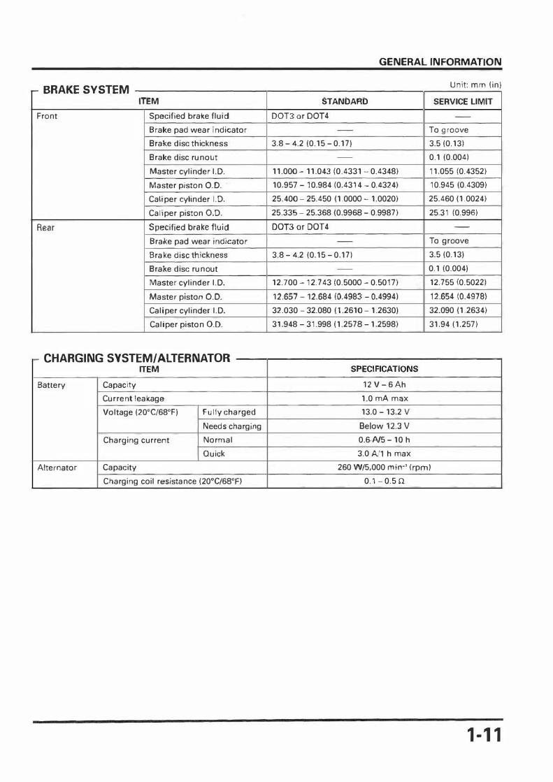
BRAKE SYSTEM Unit: mm (in)
r-
ITEM STANDARD SERVICE LIMIT
Front Speeified brake fluid DOT3 or DOT4 -
Brake pad wear indicator - To groove
Bral<e dise thiekness 3.8-4.2 (0.15-0.17) 3.5 (0.13)
Brake dise runout - 0.1 (0.004)
Master eylinder I.D. 11.000- 11.043 (0.4331 - 0.4348) 11.055 (0.4352)
Master piston O.D. · 10.957 -10.984 (0.4314- 0.4.324) 10.945 (0.4309)
Caliper eylinder I.D. 25.400-25.450 (1.0000- 1.0020) 25.460 (1.0024)
Calnper piston O.D. 25.335-25.368 (0.9968-0.9987) 25.31 (0.996)
Rear Specified brake fluid DOT3or DOT4 -
Brake pad wear indicator - To groove
Bralke dise thiekness 3.8-4.2 (0.15-0.17) 3.5(0.13)
Brake dise runout - 0.1 (0.004)
Master cylinder I.D. 12.700- 12.743 (0.5000- 0.5017) 12.755 (0.5022)
Master piston O.D. 12.657- 12.684 (0.4983- 0.4994) 12.654 (0.4978)
Caliper eylinder I.D. 32.030-32.080 (1.2610-1.2630) 32.090 ( 1.2634)
Caliper piston O.D. 31.948-31.998 (1.2578-1.2598) 31.94 (1.257)
= CHARGING SYSTEM/ ALTERNA TOR ITEM SPECIFICATIONS
Battery Capaeity 12 V- 6 Ah
Current leakage 1.0 mA max
Voltage (20°C/68°F) Fully eharged 13.0-13.2 v
Needs eharging Below 12.3 V
Charging current Normal 0.6N5-10 h
Q uiek 3.0 A/1 h max
Alternator Capaeity 260 W/5,000 min·' (rpm)
Charging eoil resistance (20°C/68°F) 0.1-0.5 .n
1-11

GENERAL INFORMATION
- IGNITION SYSTEM Unit· mm (in)
ITEM SPECIFICATIONS
Spark plug NGK DENSO
1 Standard CR8EH-9 (NGK) U24FER-9 (DENSO)
Spark plug gap 0.8-0.9 mm (0.031 -0.035 in)
Ignition co il primary peak voltage 100 V minimum
Ignition pulse generator peak voltage 0.7 V minimum
Ignition timing "F" mark 12° :t 1° BTDC at 1,500 :t 100 min-' (rpm)
Full advance BTDC 38°
r- ELECTRIC STARTER/STARTER CLUTCH ITEM STANDARD SERVICE LIMIT
Starter motor brush length 10.00-10.05 (0.394-0.396) 3.5 (0. 14)
Starter clutch gear 0.0. 45.657-45.673 (1.7975-1.7981) 45.64 (1.797)
Starter clutch outer 1.0. 62.317-62.347 (2.4534-2.4546) 62.33 (2.454)
r- LIGHTS/METERS/SWITCHES ITEM SPECIFICATIONS
Bulbs Headlight (High/low bearn) 12 v - 35/35 w x 2
Position light 12V-5Wx2
Brake/tail/license light 12 v- 21/5 w
Front tu rn signal light 12V-10Wx2
Rear tu rn signal light 12 v -10 w x 2
Instrument light 12V-1.7Wx3
Turn signal indicator 12 v -2 w x 2
High bearn indicator 12V-1.2W
Neutral indicator 12 V-2 W
Temp indicator 12V-1.7W
Fuse Main fuse 30A
Subfuse 10Ax5
Thermo OFF--+ ON 112-118°C (234-444°F) switch
ON--+ OFF Below 108°C (226°F)
1-12

GENERAL INFORMATION
TORQUE VALUES
r- STANDARD
FASTENER TYPE TORQUE
FASTENER TYPE N·m (kgf·m, lbf·ftl
5 mm boit and nut 5 (0.5, 3.6) 5 mm screw 6 mm boit and nut (lnclude SH 10 (1.0, 7) 6 mm screw flange boit) 6 mm flange boit and nut (lnclude 8 mm boit and nut 22 (2.2, 16) NSHF) 10 mm boit and nut 34 (3.5, 25) 8 mm flange boit and nut 12 mm boit and nut 54 (5.5, 40) 10 mm flange boit and nut
Torque specifications listed below are for important fasteners. Others should be tightened to standard torque values listed above.
NOTES: 1. Apply sealant to the threads. 2. Apply locking agent to the threads. 3. Apply molybdenum disulfide oil to the threads and flange surface.
-
4. Left hand threads. 5. Stake. 6. Apply oil to the threads and flange surface. 7. Apply clean engine oil to the 0-ring. 8. UBS boit. 9. U-nut. 10. ALOC boit.
ENGINE THREAD TORQUE
TORQUE N·m lkgf·m, lbf·ftl
4 (0.4, 2.9) 9 (0.9, 6.5)
12(1.2,9)
26 (2.7, 20) 39 (4.0, 29)
ITEM Q'TY DIA. (mm) N·m (kgf·m, lbf·ftl REMARKS
MAINTENANCE: Spark plug 2 10 12 (1.2, 9)
Crankshaft hole cap 1 30 15 (1.5, 11) Timing hole cap 1 14 10 (1.0, 7) Valve adjusting screw lock nut 4 6 17 (1.7, 12) NOTE6 Oil drain boit 1 12 25 (2.5, 18)
LUBRICATION SYSTEM: Oil pump mounting boit 2 6 14 (1.4, 10)
FUEL SYSTEM: Caburetor insutator band screw 4 5 5 (0.5, 3.6) PAIR check valve cover boit 4 5 5 (0.5, 3.6)
COOLING SYSTEM: Water pump drain boit 1 10 13 (1.3, 9) Water pump impeller 1 7 12 (1.2, 9) Cooling fan nut 1 3 1 (0.1, 0.7) NOTE 2
ENGINE REMOVAL/INSTALLATION: Drive sprocket setting plate boit 2 6 12 (1.2, 9)
CLUTCH/GEARSHIFT UNKAGE: Clutch center lock nut 1 16 108(11,80) NOTE 5,6 Clutch pressure plate boit 5 6 12 (1.2, 9) Gear shift stopper arm pivot boit 1 6 12 (1.2, 9) NOTE6 Gear shift cam plate boit 1 8 23 (2.3, 11) NOTE 2
1-13

GENERAL INFORMATION
- ENGINE (C t'd) on
ITEM Q'TV THREAD TORQUE
RE MARKS DIA. (mm) N·m (kgf.m, lbf·ftl
CYLINDER HEAD/VALVE:
Cylinder head side cover boit 4 s 10 (1.0, 7) Cylinder head cover boit 8 s 10 (1.0, 7)
Cam sprocket boit 4 7 20 (2.0, 14) NOTE 2
Cylinder head flange nut: 8 mm (0.3 in) 8 8 32 (3.3, 24) NOTES S mm (0.2 in) 4 s 12 (1.2, 9) NOTES
Camshaft holder boit 12 s 12 (1.2, 9)
Rocker arm shaft boit 4 5 5 (0.5, 3.S)
Cam chain tensioner lifter boit 4 s 12 (1.2, 9)
Cam chain tensioner lifter plug 2 s 4 (0.4, 2.9)
CRANKCASE/TRANSMISSION/CRANKSHAFT:
Mainshaft bearing setting plate boit 2 s 10(1.0,7)
Shift drum bearing setting plate boit 2 s 10 (1.0, 7) NOTE2 CHARGING SYSTEM/ Al TE RNA TOR:
Flywheel nut 1 12 S4 (S.5, 47) NOTE S
Stator mounting boit 3 s 12 (1.2, 9)
Ignition pulse generator mounting boit 2 5 5 (0.5, 3.S)
Stator/Ignition pulse generator wire clamp boit 1 5 5 (0.5, 3.S)
IGNITION SYSTEM:
Engine coolant temperature lECT) sensor 1 12 23 (2.3, 17)
ELECTRIC STARTER/STARTER CLUTCH:
Starter motor terminal nut 1 s 12 (1.2, 91
Starter motor front cover boit 2 5 5 (0.5, 3.S)
Primary drive gear Jock nut 1 16 88 (9.0, S5) NOTES OTHERS:
Neutra! switch 1 10 12 (1.2, 9)
Neutra! switch terminal nut 1 4 2 (0.2. 1.4)
- FRAME
ITEM Q'TV THREAD TORQUE
REMARKS DIA. (mm) N·m (kgf·m, lbf·ftl
FRAME/BODY PANELS/EXHAUST SYSTEM:
Muffler band boit 1 8 20 (2.0, 14)
Exhaust pipe joint nut 4 8 18 (1.8, 13)
Muffler mounting boit 2 8 32 (3.3, 24)
ENGINE REMOVAL/INSTALLATION:
Front engine mounting nut 1 10 39 (4.0, 29)
Rear upper engine mounting nut 1 10 39 (4.0, 29)
Rear lower engine mounting nut 2 10 39 (4.0, 29)
Engine hanger bracket boit 1 8 18 (1.8, 13)
FRONT WHEEL/SUSPENSION/STEERING:
Fork boit 2 28 22 (2.2, 1S)
Fork socket boit 2 8 20 (2.0, 14) NOTE2 Handlebar holder boit 4 8 24 (2.4, 11)
Steering stem nut 1 24 103 (10.5, 7S)
Steering top thread 1 2S See page 12-2S
Top bridge pinch boit 2 8 2S (2.7, 20)
Bottom bridge pinch boit 4 8 34 (3.5, 25)
Front axle boit 1 14 ss (S.7, 48)
Front axle pinth boit 1 8 22 (2.2, 1SI
Front brake dise boit 4 8 42 (4.3, 31) NOTE 10
Throttle housing screw 5 4 (0.4, 2.9)
1-14

GENERAL INFORMATION
:- FRAME (C t'd) on
ITEM Q'TV THREAO TORQUE
RE MARKS DIA. (mm) N.m (kgf.m, lbf.ftl
REAR WHEEL/SUSPENSION:
Rear axle nut 1 14 88 (9.0, 65) NOTE9 Driven sprocket nut 6 10 64 (6.5, 47) NOTE9 Rear brake dise boit 4 8 42 (4.3, 31) NOTE 10 Shock absorber upper mounting nut 1 10 44 (4.5, 33) NOTE 9 Shock absorber lower mounting nut 1 10 44 (4.5, 33) Swingarm pivot nut 1 14 88 (9.0, 65) NOTE 9 Chain slider screw 2 5 3 (0.3, 2.2) Chain adjuster lock nut 2 6 10 (1.0, 7)
BRAKE SYSTEM:
Front brake oil boit 2 10 34 (3.5, 25) Front master cylinder holder boit 2 6 12 (1.2, 9) Front master cylinder cover screw 2 4 2 (0.2, 1.4) Front brake light switch screw 1 4 1 (0.1, 0.7) Brake lever pivot nut 1 6 6 (0.6, 4.3) Brake lever pivot boit 1 6 1 (0.1, 0.7) Front brake cafiper mounting boit 1 8 30 (3.1, 22) NOTE 10 Front caliper pin boit (main) 1 8 18 (1.8, 13) Front caliper pin boit {sub) 1 8 23 (2.3, 17) Front caliper pad pin 1 10 18(1.8, 13) Front caliper pad pin plug 1 10 2 (0.2, 1.4) Rear brake reservoir tank boit 1 6 12 (1.2, 9) Rear brake oil boit 2 10 34 (3.5, 25) Rear master cylinder mounting boit 2 6 12 (1.2, 9) Rear master cylinder push rod nut 1 8 17 (1.7, 12) Rear master cyfinder cover screw 2 4 2 (0.2, 1.4) Rear caliper pin boit 1 8 17 (1.7, 12) Rear caliper pad pin 1 10 17 (1.7, 12) Rear caliper pad pin plug 1 10 2 (0.2, 1.4)
LIGHTS/METERS/SWITCHES:
Thermo switch 1 16 18 (1.8, 13) OTHER FASTENERS:
Side stand pivot boit 1 10 10 (1.0, 7) Side stand lock nut 1 10 29 (3.0, 22) NOTE 9 Side stand switch boit 1 6 10 {1.0, 7)
1-15

GENERAL INFORMATION
TOOLS
NOTES: 1. Alternative tool.
2. Newly provided tool.
DESCRIPTION TOOLNUMBER REMARKS REF.SEC.
Attachment, 22 x 24 mm 077 46-001 0800 13 Attachment, 24 x 26 mm 077 46-0010700 6 Attachment, 28 x 30 mm 07746-1870100 8 Attachment, 32 x 35 mm 07746-0010100 11, 13,6 Attachment, 42 x 47 mm 077 46-001 0300 11, 12, 13 Bea ring installer 37.42 07XMF-KGB0100 11 Bearing installer 37.5 07XMF-KGB0200 11 Bearing remover head 077 46-0050400 12, 13 Bearing remover head 07936-GE00200 6 Bearing remover head 07936-KC1 0200 11 Bea ring remover shaft 07936-GE00100 6 Bearing remover shaft 07936-KC10100 11 Bea ring remover shaft 07746-0050100 12, 13 Bea ring remover weight 07741-0010201 11 Carburetor float level gauge 07 40 1-00 1 0000 5 Clutch center holder 07724-0050002 8 Crank shaft assembly collar 07965-VM00100 11 Crank shaft assembly shaft 07965-VM00200 11 Driver 07749-0010000 6, 8, 11, 12, 13 Driver shaft 07946-MJ00100 13 Flywheel holder 07725-0040000 15 Flywheel puller 07KMC-HE00100 15 Fork seal driver body 07747-0010100 12 Fork seal driver attachment 07947-KA20200 12 Gear holder 07724-0010200 17 Mechanical seal driver attachment 07945-4150400 6 Mechanical seal driver 07PMD-KBP0100 11 Peak voltage adapter 07HGJ-0020100 16 Pilot, 10 mm 077 46-0040100 6 Pilot, 12 mm 077 46-0040200 8 Pilot, 15 mm 077 46-0040300 11, 12, 13 Pilot, 17 mm 077 46-0040400 11 Pilot, 20 mm 077 46-0040500 11 Pilot, 25 mm 077 46-0040600 11 Pilot screw wrench 07908-4730002 5 Plate, 200 x 300 x 20 07XMF-KGB0300 11 Snap ring pliers 07914-SA50001 14 Driver handle 07953-MJ 10200 12 Steering stem driver 07946-MBOOOOO 12 Driver attachment 07953-MJ10100 12 Steering stem cap nut wrench 07716-0020400 12 Steering stem socket wrench 07916-3710101 12 Universal bearing puller 07631-0010000 11 Vacuum gauge attachment 07510-3000100 3 Valve guide driver, 5 mm 07942-MA60000 9
1-16

GENERAL INFORMATION
(C t'd) on
DESCRIPTION TOOLNUMBER REMARKS REF.SEC.
Valve guide rea mer 07984-MA6000 1 9
Valve spring compresser 07757-0010000 9
Valve spring compresser attachment 07959-KM30101 9
Valve seat cutter
Seat cutter, 24.5 mm (45. IN) 07780-0010100 9
Seat cutter, 22 mm (45. EX) 07780-0010701 9
Flat cutter, 25 mm (32.1N) 07780-0012000 9
Flat cutter, 22 mm (32. EX) 07780-0012601 9
lnterior cutter, 22 mm (60. IN/EX) 07780-0014202 9
Cutter helder, 5 mm 07781-0010400 9
1-17

GENERAL INFORMATION
LUBRICATION & SEAL POINTS
,_ ENGINE LOCATION
Camshaft camsurf/journals Valve stem (valve guide sliding surface)/stem end Rocker arm slipper surface Rocker arm shaft sliding surface Connecting rod small end inner surface Clutch outer sliding surface M-3, C-4, C-5 gear (shift fork grooves) Clutch outer guide surface Gear (engaging and bearing portion) Piston pin outer surface Gear shift fork inner surface and shaft
Piston pin ho le and outer cylindrical surface Piston ring whole surface Primary drive gear lock nut threads and seating surface Flywheel lock nut threads and seating surface Clutch disk lining surface Cylinder stud boit threads Valve adjusting nut threads Cam chain whole surface Connecting rod bearing surface Clutch center Jock nut threads and seating surface Oïl pump inner rotor Cylinder inner surface Camshaft holder boit threads and seating surface Clutch lifter piece outer surface Clutch lifter arm shaft outer surface Starter clutch sliding a rea Each ball/needle bearing sliding area Each 0-ring Gearshift spindle shaft outer surface Oil strainer screen rubber frame Scavenging pipe rubber parts
Right and left crankcase mating surface
-
Thermo switch threads Alternator and ignition pulse generator grommets Water pump mechanical seal flange
Cam chain tensioner tighting boit threads Gearshift cam plate boit threads Mainshaft bea ring set plate boit threads Gearshift drum bearing set plate boit threads Fan motor shaft threads Cam sprocket boit threads
Cylinder head cover gasket
1-18
MATE RIAL
Molybdenum disulfide oïl (a mixture of 1/2 angine oïl and 1/2 molybdenum disulfide greaseJ
Engine oïl
Sealant
Locking agent
Honda Bond A or equivalent
REMARKS

GENERAL INFORMATION
FRAME
LOCATION MATERIAL RE MARKS
Clutch lever pivot sliding surface Multi-purpose grease
Throttle grip pipe rolled up portion Rear brake pedal pivot sliding surface Gearshift pedal pivot sliding surface Side stand pivot sliding surface Front wheel dust seal lip a rea Rear wheel dust seal lip area Rear wheel 0-ring wh ole Final driver flange gap with rear hub Final driver fi ange dust seal lip a rea
Steering head upper bearing Grease
Steering head lower bea ring Steering head dust seal lips Rear caliper pin boit Rear master cylinder push rod contact area Front brake lever pivot and piston contact area Front brake lever pivot sliding a rea Front fork oil seal lips
Swingarm pivot dust seal lips Swingarm pivot bearing and center collar sliding surface Swingarm pivot bush and collar sliding surface Speedometer gear box inside Speedometer gear sliding portion
Steering top threads Engine oil
Front engine hanger boit threads Rear engine hanger boit threads Upper engine hanger boit threads
Brake master cylinder pistons and cups DOT 3 or DOT 4 brake fluid
Rear caliper piston sliding surface
Throttle cable casting inside Silicone grease
Clutch cable casing inside Caliper piston seal sliding surface Caliper pin sliding surface
Final driven flange boit threads locking agent Rear caliper nut threads Front caliper pin threads Front caliper nut threads Fork socket boit th reads
Handle grip rubber inside surfaces Honda band A or Cemedine #540
Front fork inside Fork fluid
1-19

GENERAL INFORMATION
CABLE & HARNESS ROUTING
BRAKE HOSE
RIGHTFRONT
TURN SIGNAL WIRE
1-20
THROTILE GABLES
LEFT HANDLEBAR
SWITCHWIRE
\..-1------- COMBINATION
TURN SIGNAL
RELAYWIRE
METER WIRE
LEFTFRONT
TURN SIGNAL WIRE

LEFT HANDLEBAR
SWITCH WIRE
RADIA TOR RESERVE
TANK OVER FLOW TUBE
SPEED SENSOR
WIRE
THROTTLE GABLES ENGINE STOP
SWITCHWIRE
SIPHON TUBE
GENERAL INFORMATION
AIR INJECTION HOSE
MAIN WIRE HARNESS
FUEL TUBE
1-21

GENERAL INFORMATION
THROTTLE CABLES ENGINE COOLANT
TEMPLATURE SENSOR
WIRE .
STARTER ALTERNATOR GROUND NEUTRAL SWITCH MOTOR WIRE WIRE WIRE WIRE
1-22
THERMO SWITCH
WIRE
SPEED SENSOR WIRE
(IIG TYPE ONL Y)
MAIN WIRE
HARNESS
SIDE STAND
SWITCHWIRE

S IPHON TUBE
CLUTCH CABLE WATER HOSE
GENERAL INFORMATION
SPEEDOMETER
FAN MOTOR SWITCHWIRE
BRAKE HOSE
1-23

GENERAL INFORMATION
REAR BRAKE
LIGHT SWITCH WIRE
DRAIN TUBE
1-24
REAR SPAAK PLUG WIRE
STARTING ENRICHMENT
(SE) VALUE CABLES
AIR SUPPL Y HOSE
WATERTUBE
FRONTSPARK PLUG WIRE

MAIN WIRE HARNESS
BATTERY NEGATIVE WIRE
GENERAL INFORMATION
REAR BRAKE
LIGHT SWITCH
WIRE
IGNITION CONTROL MODULE (ICM) WIRE
STARTER RELAY
SWITCHWIRE
BA TTERY POSITIVE WIRE
1-25

GENERAL INFORMATION
RIGHT REAR TURN SIGNALWIRE
1-26
TAIL/BRAKE LIGHTWIRE
LEFT REAR TURN SIGNAL WIRE

EMISSION CONTROL SYSTEMS
SOURCE OF EMISSIONS
GENERAL INFORMATION
The combustion process produces carbon monoxide and hydrocarbons. Controlling hydrocarbon emission is very important because, under certain conditions, they react to form photochemical smog when subjected to sunlight. Carbon monoxide does not react in the same way, but it is toxic.
Honda Moter Co., Ltd. utilizes lean carburetor settings as weil as other systems, to reduce carbon monoxide and hydrocarbons.
CRANKCASE EMISSION CONTROL SYSTEM
The engine is equipped with a closed crankcase system to prevent discharging crankcase emissions into the atmospher. Blow-by gas is returned to the combustion cham ber through the air cleaner and carburetor.
AIR CLEANER CASE
CARBURETOR
� :FRESHAIR
: BLOW-BY GAS
1-27

GENERAL INFORMATION
EXHAUST EMISSION CONTROL SYSTEM (PULSE SECONDARY AIR INJECTION SYSTEM)
The exhaust emission control system consists of a secondary air supply system which introduces filtered air into the exhaust bases in the exhaust port. Fresh air is drawn into the exhaust port whenever there is a negative pressure pulse in the exhaust system. This charge of fresh air promotes burning of the unburned exhaust gases and changes a considerable a mount of hydrocarbons and carbon monoxide into relatively harmless carbon dioxide and water vapor. This modal has the pulse secondary air injection (PAIR) control valve and PAIR check valve. Pair check valve prevents reverse air flow through the system. The PAIR control valve reacts to high intake manifold vacuum and will eut off the supply of the fresh air du ring engine deceleration, thereby preventing afterburn in the exhaust system.
No adjustment to the pulse secondary air injection system should be made, although periodic inspection of the components is recommended.
PULSE SECONDARY AIR INJECTION (PAIR)� CHECK VALVE �
1-28
AIR CLEANER
PULSE SECONDARY AIR INJECTION (PAIR) CONTROL VALVE
EXHAUST PORT