Embed Size (px)
Citation preview

Energy and Indoor Air Quality Recommendations for Cold Climate Habitat for Humanity Homes
Report Number: FSEC-CR-1647-06
August 2006
Produced for:
U.S. Department of Energy under supplemental funding to the Building America Industrialized Housing Partnership
DOE Contract #DE-FC26-99GO10478 UCF Contract 20126030
and
Habitat for Humanity International and Michigan Habitat for Humanity Jimmy Carter Work Project and Congress Building America Affiliates
Habitat Affiliates in the Cold Climate
Submitted by:
David Beal Janet McIlvaine
Contract Report

~~ wwwwww..BBAAIIHHPP..oorrgg ~~
Building America’s Industrialized Housing Partnership
Energy and Indoor Air Quality Recommendations for Cold Climate Habitat for Humanity Homes
By
David Beal Janet McIlvaine
Florida Solar Energy Center A Research Institute of the
University of Central Florida
August 2006
Produced for U.S. Department of Energy Under Supplemental Funding to the
Building America Industrialized Housing Partnership DOE Contract #DE-FC26-99GO10478
UCF Contract 20126030
FSEC-CR-1647-06

Disclaimer This report was prepared as an account of work sponsored by an agency of the United States government. Neither the United States government nor any agency thereof, nor any of their employees, makes any warranty, express or implied, or assumes any legal liability or responsibility for the accuracy, completeness, or usefulness of any information, apparatus, product, or process disclosed, or represents that its use would not infringe privately owned rights. Reference herein to any specific commercial product, process, or service by trade name, trademark, manufacturer, or otherwise does not necessarily constitute or imply its endorsement, recommendation, or favoring by the United States government or any agency thereof. The views and opinions of authors expressed herein do not necessarily state or reflect those of the United States government or any agency thereof.

Acknowledgements This work was conducted under the United States Department of Energy (DOE) Building America Industrialized Housing Partnership (BAIHP). Building America is a collaborative effort between building scientists and home builders striving to build homes that save 15-50% energy while maintaining or improving indoor air quality, durability, and comfort at little to no first cost. This is accomplished using a Systems Engineering, also known as “Whole House” and “House as a System,” approach. For full information, please visit www.buildingamerica.gov and www.baihp.org. The authors appreciate the support and input of DOE Building America program managers, Edward Pollock and George James; DOE contract administrator, William Hasslebacher, NETL; and BAIHP Project Director Subrato Chandra. We are grateful for our 10 year partnership with Habitat for Humanity International and its domestic affiliates. We appreciate the Habitat affiliates that participated in the Jimmy Carter Work Project, the Congress Building America initiative, and our field work as reported in this document. Their willingness to share their ideas and challenges made this collaboration possible and it is for them and their fellow Habitat affiliates that we prepared this summary and recommendations.

Table of Contents Executive Summary........................................................................................................................i Introduction....................................................................................................................................1 Observations...................................................................................................................................1 Duct Leakage Concepts .................................................................................................................2 Supply Leakage....................................................................................................................3 Return Leakage ....................................................................................................................3 Reducing Duct Leakage: Three Primary Approaches .........................................................4 Combustion Safety Concepts ........................................................................................................5 Water Heater Solutions........................................................................................................6 Furnace Solutions ................................................................................................................7 Combustion Closet Construction.........................................................................................7 Energy Simulation Analysis Overview ........................................................................................8 Equipment Improvements....................................................................................................8 Envelope Improvements ......................................................................................................9 Energy Simulation Analysis Results ............................................................................................9 Using Tables 1-5 to Predict Energy Savings .......................................................................9 Table 1 Energy Use and Cost Comparison of Foundations with Two Heating Types......10 Table 2 Equipment Improvements Savings .......................................................................11 Table 3 Envelope Improvements Savings .........................................................................12 Table 4 Duct Tightening Savings ......................................................................................13 Table 5 Water Heating Energy Use and Cost ....................................................................14 Cautions .............................................................................................................................14 Energy Simulation Analysis Summary......................................................................................15 Insulation ...........................................................................................................................15 Combustion Safety and Air Sealing...................................................................................15 Duct Sealing.......................................................................................................................15 Recommendations........................................................................................................................16 Contact Information....................................................................................................................17 References.....................................................................................................................................18 Partnership Invitation to HFH Affiliates...................................................................................19
i
Executive Summary
During June 2005, BAIHP researchers visited six Habitat for Humanity (HFH) affiliates in Michigan participating in the 2005 Jimmy Carter Work Project (JCWP) and HFHI’s Congress Building America (CBA) program. The visit combined participation in the week long Benton Harbor HFH “blitz build” as energy advisors with site visits to five other affiliates in the area, to conduct an assessment of local building methods concentrating on energy efficiency. The evaluation included duct and whole house air tightness testing in one home at each affiliate. All homes observed were built in conjunction with the 2005 JCWP, and all visited affiliates were also building a CBA house. The homes being built by the six affiliates were very similar, with the biggest difference being the foundation type. Many homes had 2X4 walls, and R-5 basement walls (not all affiliates, some 2X6 and R-20). Most homes had high efficiency sealed combustion gas appliances (furnace and water heater), although one affiliate had a mix of sealed and atmospherically vented gas appliances. All homes but one had good Low-E windows. All observed duct systems were leaky. When coupled with atmospherically vented combustion appliances this duct leakage can cause pressure induced combustion by-product problems, including back drafting of gas appliances. When atmospherically vented appliances are used great care must be exercised to avoid pressure induced back drafting of the appliances. In addition, there are large energy penalties when the leaky ducts are in a vented crawlspace or attic. Power vent or direct vent appliances not only save energy, they are much safer as they either get their combustion air from outside or force the combustion products out of the house.
A base case, minimum efficiency three bedroom, one bath, 1104 ft2, heated house plan was analyzed using a computer model. A set of improvements to the base case was modeled and compared to the base case to generate energy efficient building recommendations. Five different foundations were analyzed: slab on grade, sealed and vented crawlspaces, and conditioned and unconditioned basements. Results of the analysis show that wall insulation and equipment efficiency are the primary avenues towards energy efficiency in the houses. Cost and energy efficiency for gas and electric energy users are also discussed. Specific recommendations include:
• Use high efficiency (AFUE > 90%), direct or forced vent gas furnaces and water heaters rather than atmospherically vented ones. Not only are they more energy efficient, they eliminate many health and safety concerns relating to combustion by-products.
• Build a minimum of a 2X6 wall with R-19 insulation, and increase crawlspace and basement wall insulation to match.
• Attic insulation levels above R-30 and Low-E windows provide smaller savings than equipment efficiency increases and wall insulation increases. Five of the six affiliates visited have already adopted low-e windows.
• Build better duct systems. The current strategy often relies on a leaky duct system and a leaky interior (floors and partition walls) to distribute the heat. Ducts should not use building cavities for air paths, should be designed to adequately supply and return the conditioned spaces served, and be leak free.
• Consider a high efficiency, tankless, instantaneous gas hot water heater. • Install a hard wired carbon monoxide sensor with battery backup in the main body of any
house with gas furnace, gas water heater or attached garages.

ii
• Provide exhaust fans in bathroom and kitchen for moisture control • After atmospherically vented gas furnaces and water heaters have been eliminated, reduce
whole house infiltration by making the air barrier (e.g. house wrap, rigid insulation, or exterior sheathing) separating conditioned space from outside continuous air tight -- seal all holes created for wiring and plumbing, seal air barrier at edges and seams.
• Make sure that there is a continuous drainage plane behind exterior finishes (except stucco which is face-sealed)
• Provide a vapor retarder over ground in crawlspaces and under slabs (also acts a capillary break)
• Have heating and cooling equipment sized with industry standard sizing calculation such as the Air Conditioner Contractors of America’s Manual J calculation.
The analysis presented here is a review of commonly implemented energy improvements but going beyond these levels of efficiency may be cost effective and in line with Habitat principles. For additional information review these publications:
• Habitat Congress Building America: COLD CLIMATE CASE STUDY for Pontiac, Michigan by Building Science Corporation. Free at www.building science.com.
• Building America Best Practices Series: Volume 3 (Cold Climate). Free at www.buildingamerica.gov
• Builders Guide To Cold Climates. $45 in the “Bookstore” of the Energy and Environmental Building Association (a Building America partner) at http://www.eeba.org/

1
INTRODUCTION During the 2005 Jimmy Carter Work Project (JCWP), Building America Industrialized Housing Partnership (BAIHP) researchers met with six Michigan-based participants in the Habitat for Humanity International (HFHI) Congress Building America (CBA) initiative. The JCWP and CBA raise awareness of affordable housing issues in the general media and with congressional members respectively. The visited Habitat for Humanity (HFH) affiliates were
• Blue Water HFH (Port Huron, MI) • Monroe County HFH (Monroe, MI) • Lakeshore HFH (Holland, MI) • Kalamazoo Valley HFH (Kalamazoo, MI) • Lansing HFH (Lansing, MI) • Harbor HFH (Benton Harbor, MI)
The visit was conducted to assess regional building practices as well as affiliate practices. All of the houses visited were built in conjunction with the CBA and JCWP. The affiliates built very similar houses, with the largest difference being the foundation system used. Finished and unfinished basements, sealed crawlspaces, vented crawlspaces, and slab-on-grade houses were seen. Several different structural systems for basements were observed, including: poured concrete, ICF block, and panelized systems-typically “Reward Wall System.” All of the houses were frame construction (mainly 2X4 walls, some 2X6), with heat and usually hot water provided by natural gas. None of the homes were built with air conditioning. Window areas were conservative. Most of these JCWP and CBA houses had good low-E double pane windows. OBSERVATIONS Many of the houses visited were built with 2X4 walls and R-13 fiberglass batt insulation. Basement wall insulation ranged from R-5 to R-14 (ICF). All homes had double-pane insulated glass, and all but one house observed had Low-E windows. Most had high efficiency, direct or power vent gas appliances. One affiliate had a mix of atmospherically vented and direct/power vented equipment. Researchers tested houses at five of the six affiliates and found a range of whole house air tightness from 2.9 to 8.5 ACH50. Average new construction across the country is approximately 6.0 ACH50. Duct air tightness was also measured and found to greatly exceed expected levels for new construction. All of the units tested had extremely leaky duct systems; in some cases they were so leaky that they were unable to reach the standard test pressure. The systems routinely used building cavities as part of the duct system, with unducted returns running through interior walls and panned floor joists being the norm. There is room for improvement in both of these air tightness areas; however combustion safety issues must be addressed before air tightness improvements are broadly implemented.
JCWP-CBA House built by Lansing (MI) Habitat for Humanity in June of 2005

2
This is an important issue that deserves serious consideration because the duct system integrity affects not only energy use, but also (and more importantly) combustion safety and indoor air quality. A discussion follows in Duct Leakage Concepts and Combustion Safety for those unfamiliar with the implications of duct leakage and the generally accepted approaches to avoiding the potentially dangerous results. In basement and sealed crawlspace houses the equipment was in the crawlspace or basement. The total duct leakage was large, but the duct leakage to the outside was minimal as the equipment and ducting was in the conditioned envelope. All is not well, however, as there can still be large internal pressures generated by duct leakage combined with door closures, most noticeably when a good, tight sealing basement door is installed. In houses with a centralized return, the return air register and pathway was typically undersized. This creates a negative pressure in the zone where the furnace is located and forces infiltration into that space. The centralized returns observed were typically through a 2 X 4 interior wall where the bottom plate and subfloor was eliminated to create an air flow path (see photo, right.) These were typically in the living room or hall and served a space with four or more supplies registers. A preferable approach would be a vertical return air chase housing a return duct (from a return air grille to the furnace) sized using ACCA Manual D to promote return air flow equal in volume to the sum of the supply air flows serving the space. One mechanical contractor had installed the gas furnace on a riser designed to allow the later installation of a heat pump/air conditioning coil. This saves much labor when the homeowner wants to switch to a heat pump or add air conditioning to their house. DUCT LEAKAGE CONCEPTS For further detail see: Procedures for HVAC System Design And Installation, a Building America document available online at http://www.eere.energy.gov/buildings/building_america/pdfs/db/35625.pdf Conventional forced air heating and cooling systems employ an air distribution system that includes an air handler and a duct system. The air handler is designed to remove air from the house (return), condition it, and supply it back to each room. Duct leakage can occur on either the supply side or the return side of the air handler as well as in the air handler itself. Both supply and return leaks cause air to move in unplanned, unpredictable ways, usually through unconditioned spaces and often bypassing air, thermal, and moisture barriers.
Bottom plate and subfloor cut out to create return air pathwayBottom plate and subfloor cut out to create return air pathway

3
Supply leakage When supply ducts leak to the outside, they create a negative pressure in the house because more air is being removed than is being supplied. The negative pressure draws air from outside and/or unconditioned spaces (infiltration) through holes in the house’s air barrier potentially leading to:
• Back drafting of atmospheric combustion devices
• Introduction of outside air pollution, pollen, and other allergens
• Introduction of air borne particles (dust, insulation, VOCs, building material particles) from floor, wall, ceiling cavities
• Degraded comfort (temperature, humidity) • Greater conditioning load • Reduced system life
Supply leaks also spill conditioned air into unconditioned spaces, wasting energy, and creating the potential for mold growth, condensation, and rot. Leaks typically can occur at joints (see photo, right). Return leakage When return ducts leak, part of the return air is drawn from unconditioned spaces, or outside, instead of the house. This typically occurs when building cavities are used as return air pathways (see photo, below).This dirty air often bypasses the system’s filter. The leakage creates a positive pressure in the house because more air is being supplied than is being removed. The positive pressure forces air through holes in the house’s air barrier (exfiltration). Return duct leakage leads to:
$ Lowered heating and cooling capacity with degraded comfort. $ Introduction of outside and/or unconditioned air into the air handler, with its attendant moisture, dirt, and pollutants. $ Increased conditioning load $ Reduced system life
Several typical building flaws related to poorly constructed air distribution systems cause most pressure related building problems. Large amounts of duct leakage can cause pressure imbalances inside the house, with predominant supply leaks causing negative pressures, and predominant return leaks causing positive pressures in the house. Further exacerbating pressure imbalances are door
After: Mastic and mesh duct sealing improves IAQ and energy efficiency.
Before: Tape failure at duct joint led to condensation, mold, and decay.
Unducted return air plenum pulls air from connected floor, wall, and ceiling cavities
Frame for filter back return grill.
Unducted return air plenum pulls air from connected floor, wall, and ceiling cavities
Frame for filter back return grill.

4
closures in the house. A basement door can be especially problematic, sealing off half of the conditioned volume of the house from the other half. If inadequate provisions are made for return air to flow from the closed rooms back to a centrally located A/C return grill, large pressures are generated between areas of the house. The operation of exhaust fans also depressurizes the house. A dryer is essentially a large exhaust fan, and is often located in close proximity to the gas water heater and furnace. Any negative pressure in the zone where atmospherically vented gas appliances are can back-draft the appliances. If an effort is made to fix the duct system, and some leaks are fixed and some aren’t, air handler operation could cause significant negative pressures in the house. Repair of the supplies only (most often done, as supply leaks can be felt with your hand) often happens without repairing returns. If the duct work and equipment are all in the crawlspace or basement, this repair can cause the return leaks to induce a negative pressure in the crawlspace or basement, possible back-drafting any atmospherically vented appliances in the same space. Thought and care must be used before and during any duct repair or building air tightening campaign is carried out. The observed systems and interior air barriers are currently so leaky that neither supply leaks nor return leaks are predominate. Several of the homes have provisions for outside air inlets with gravity dampers. These dampers can help avoid combustion exhaust back drafting by allowing outside make up air into the house to neutralize negative pressures. They are an important safety feature. The dampers must be set correctly to open at small negative pressures. Homeowner education is necessary to keep the homeowner from tampering with the vent when they feel the incoming cold outside air. Reducing Duct Leakage: Three Primary Approaches 1. Sealed ducts: Studies of the duct leakage
phenomenon over the past 20 years have found that avoiding building cavities in favor of ducted air distribution paths which are sealed with a combination of fiberglass mesh and mastic is inexpensive and cost effective. This includes abandoning wall cavity central returns in favor of platform style returns (photo, right.) Several residential studies have shown that these simple repairs can reduce duct leakage to a Qn of less than 0.03-0.051, saving 15 or 20% of cooling and heating costs respectively or about $60 annually2. At an installed cost of about $200, the
1Duct leakage to outside measured at test pressure of 25 Pascals divided by conditioned floor area, referred to as Qn. If a 1000 ft2 house had a CFM25Out of 50, the Qn would be 0.05 2Compilation of findings by: Cummings, Tooley, and Moyer, 91 and 93. Davis, 91. Evans and Tsal, 96. Manclark and Davis, 96).
A Ducted return air plenum pulls air only form the conditioned space - not form connected floors, walls, or ceilings. Note frame for filter back grill

5
improvement generally pays for itself in less than 4 years. The basic premise of this concept is that the air barrier of the duct system needs to be continuous and directly connected to the air barrier of the house to prevent air from unintentionally entering or escaping the system. Much like a plumbing system, the duct system should be a controlled pathway for conditioned air only.
2. Unvented attics, crawlspaces, or basements: In recent years, researchers began to explore
other ways to reduce the impacts of duct leakage (Rudd 1998). Relocating the thermal and air barriers of the house to the outer edges of the structure creates either an insulated roof deck or foundation walls or basement. The space containing the ducts is not vented to the outside. Research to evaluate the effectiveness of this method is in progress. The Michigan houses tested with all equipment and duct work housed in basements or sealed crawlspaces had minimal, or no, duct leakage to the outside. However, there can still be internal pressures generated by door closures or undersized returns, leading to combustion by-product problems.
3. Interior ducts: This concept involves putting the entire
forced air system, including the air handler, inside the conditioned space (Photo, right). Technically, this means inside the air boundary as well as the thermal boundary, and within the space that is served by the conditioning system. Michigan homes with basements or conditioned crawlspaces can have interior ducts if all duct work is placed in the basement or sealed crawlspace. Field data evaluating the success of this strategy is scant. The primary challenges in this approach involve establishing an air barrier around the ducts, overcoming code challenges, and integrating the new detail into the design and construction process. Theoretically, interior ducts will yield the savings of eliminating duct leakage plus the savings of reduced thermal gain/loss of the duct system.
COMBUSTION SAFETY CONCEPTS For further detail, see Habitat for Humanity International Publication, “Combustion Equipment Safety.” Available online at: http://www.habitat.org/env/pdf/combustion_saftey.pdf Small negative pressures in the house (2 to 3 Pascals) may stop the establishment of draft in the flue, slightly larger pressures (5 Pa) may back draft combustion appliances that have established draft. This can be extremely hazardous to the health of the occupants. Any efforts made to achieve a more air-
Interior duct chase for supply ducts separated from the attic by a dry wall air barrier
Interior duct chase for supply ducts separated from the attic by a dry wall air barrier

6
tight house or duct system could negatively impact this situation by causing larger pressure excursions, making a bad situation even worse. Affiliates can choose either atmospherically vented or direct and power vented gas hot water heaters and furnaces. This equipment is often in a small, closable area utilized as a utility room or basement with a washer and dryer in the same space; a situation that has the potential of producing elevated carbon monoxide (CO) levels in the house by back drafting the combustion appliances, as well as having a negative effect on the indoor air quality by introducing other combustion byproducts. Many factors affect the draft of a combustion device including ambient conditions, vent stack configuration and height, vent stack temperature, and internal house pressures. When ambient conditions are cold, the vent stack is cold, and there may be significant air flowing down the vent stack; both conditions causing the establishment of draft to be difficult or impossible. Cold temperatures outside can cause larger negative pressures inside by increasing the stack effect on the building, or the tendency for exfiltration (inside air escaping the building) to be increased by larger temperature differences between the inside and outside of the building. The National Fire Protection Agency’s Fuel and Gas Code (NFPA 54) address the issue of make-up air for combustion equipment by specifying that atmospherically vented combustion appliances must be provided with outside air. Their basic recommendation is that the room containing the atmospheric vented combustion appliance is vented to the outside with two openings totaling a minimum of 100 in2 free area, one within 12 inches of the floor, and one within 12 inches of the ceiling. This is based on the BTU input rating of all of the combustion devices. In the past team members have seen these code-mandated make-up air vents deliberately blocked by homeowners in an attempt to keep uncomfortable outside air out of the house. Water Heater Solutions The BAIHP team has identified several possible alternatives to an atmospherically vented gas water heater. There may be other solutions in addition to those listed below: • Use electric water heaters • Use power vent or direct vent (photo, right) gas water heaters • Build a combustion closet that is sealed from the house • Use instantaneous gas water heaters mounted outside the house Standard electric water heaters are inherently more efficient than standard efficiency gas units, using over 90% of their input energy to deliver hot water. Their standby loses are smaller than that of tank-style residential gas water heaters, as tank-style gas water heaters have a flue in their middle, losing energy up the stack.
Power vent gas water heaters have an electric fan that creates a controlled air flow from outside to the combustion chamber to the exhaust. The fan may be either on the air supply side or the air exhaust side of the unit. In both cases, the fan is connected to a valve that regulates the flow of gas to the unit. If the vent path is obstructed by debris, the supply of gas is reduced. No indicator lights or signals alert the homeowner to this situation. If the fan motor fails, the valve is closed and gas supply to the water
Double wall pipe sends exhaust air (red) out through core and brings combustion air (green) in through outer sleeve
Direct Vent Gas Water Heater
Double wall pipe sends exhaust air (red) out through core and brings combustion air (green) in through outer sleeve
Direct Vent Gas Water Heater
Double wall pipe sends exhaust air (red) out through core and brings combustion air (green) in through outer sleeve
Direct Vent Gas Water Heater

7
heater is cut off completely. Motor failure is generally precipitated by high moisture content exhaust air. Direct vent gas water heaters also draw combustion air directly from outside, rather than the space surrounding them. However, they rely on temperature difference to establish the controlled flow of air into and out of the water heater. Instantaneous gas water heaters that are mounted outside the conditioned space offer a fifth alternative. These units offer significant energy efficiency increases compared to tank type gas water heaters by eliminating standby loses. They free up several square feet of expensive interior floor space by removing the tank from the interior. Furnace Solutions Pressure imbalances in houses are most often caused by internal fans, and the culprit is most often the furnace’s own air handler fan. Several solutions to this problem can be employed.
• Hydronic systems that use radiators for heat. There can be no air conditioning retrofit with
these systems. • Building a correctly sized, air tight duct system. This requires training for your heating and air
conditioning contractor, as well as vigilance and understanding on the part of the affiliate. • Using no atmospherically vented gas appliances in the house. This mandates the use of a sealed
combustion furnace or an electric heat pump and an alternative water heating system, covered above.
• Put appliance in a combustion closet sealed form the house, and vented to the outside.
• A suitably sized passive air inlet should be installed, typically with a barometric damper, which would open and relieve the pressure buildup in the house. These units let in unconditioned outside air (unless installed in the air handler’s return before the filter), and increase the load on the heating and cooling system. This system will provide ventilation air to the house, but it doesn’t address the underlying problem causing the pressure imbalances.
Combustion Closet Construction Closet construction (illustration, right) can follow two paths, the closet either opening to the inside or to the outside. In both cases, if there are atmospherically vented gas appliance present, there needs to be venting to the outside as prescribed by the NFPA provisions for venting. Homeowner education becomes very important to

8
prevent the resident from deliberately closing the venting to stop the introduction of outside (uncomfortable) air into the house. If the closet opens to the inside two issues arise: homeowners using the closet as a storage area, and the interior door not sealing thoroughly. If the closet opens to the outside the issues are the cost of an exterior door, or an unsightly closure method (access panel made of siding), and the potential of the closet being used for storage. The closet walls should be insulated, and sealed from the main body of the house. If the closet opens to the inside, a better quality door with added weather stripping, or an exterior door, should be used to maintain the seal when the door is closed. ENERGY SIMULATION ANALYSIS OVERVIEW One of the focuses of this field work was to generate recommendations for the region’s many affiliates for building more energy efficient homes. These recommendations were generated by computer analysis using a pre-release version of Energy Gauge USA 2.52; as such the results are preliminary, pending release of the software. Given the similarity of the construction, one basic Michigan frame house with basic double pane windows was modeled over conditioned and unconditioned basements, sealed and vented crawlspaces, and slab-on-grade construction. This is referred to as the “Base Home.” The Base Home was located in Muskegon, MI and featured:
• 1104 ft2 • 3 bedrooms - 1 bath • 110 sq. ft. window area (10% of floor area) - 40 sq. ft. door area.
o Basements have an added 55 sq. ft of window area. • No cooling system, forced air heating with leaky duct work. • More energy related characteristics of the Base Home are described below
The improvements analyzed can be broken down into two categories: equipment and envelope improvements. Equipment improvements are achieved by using higher efficiency furnaces and hot water heaters. Envelope improvements include increasing R-values of building components, better windows, and improved foundation systems. Improvements analyzed were: Equipment Improvements
• Heating o BASE HOME 1) Gas AFUE =0.78, 2) Electric Strip heat COP=1 o IMPROVED 1) Gas AFUE =0.92, 2) Electric HSPF 8.3 heat pump
• Hot Water o BASE HOME 1) Gas EF=0.56, 2) Electric EF=0.92 o IMPROVED 1) Gas EF=0.85, 2) Electric EF=0.92 (no change)
• Ducts o BASE HOME Leaky ducts (Qn= 0.1) o IMPROVED Tight ducts (Qn= 0.03)

9
Envelope Improvements • Insulation package
o BASE HOME R-30 ceiling R-13 wall, R-5 crawlspace or basement wall. o IMPROVED R-40, R-22, R-19 respectively
• Windows o BASE HOME Double pane U=0.57, Clear o IMPROVED Double pane U=0.32, SHGC=0.32
When energy improvements are proposed to affiliates, the volunteer friendliness of the options must be considered. For this reason under floor insulation was not considered, as we have found it generally rejected by affiliates because volunteers dislike installing insulation it. Instead crawlspace or basement wall insulation was considered. This is not ideal for a vented crawlspace foundation. ENERGY SIMULATION ANALYSIS RESULTS Analysis results are presented in five tables reporting estimated heating energy use in Mbtus and projected costs, based on fuel type. Table 1 shows energy use and costs for unimproved Base Houses, heated with both gas and electric furnaces, Tables 2-4 show predicted savings for equipment, envelope, and duct system upgrades. The performance gains are expressed as a percentage on Tables 2-4. Table 5 shows the estimated energy use and costs of various hot water heater options. An example calculation is shown in Table 6. Energy cost estimates were generated using $5.80 per Mbtu for gas and $18.46 per Mbtu for electricity ($0.58/therm gas and $0.063/kwh electric)3. Please remember this is a simulation, making many assumptions that may not be applicable to a Habitat family. In additions, the tables’ results are somewhat generalized, resulting in a large margin of error for the process (+5%). These analysis results are best used for comparing the relative benefits of improvements, not as actual estimates of energy use or cost. Using Tables 1 – 5 to Predict Energy Savings An estimate (+3%) of the amount of energy an 1100 sq. ft. Habitat house will use for water and space heating can be generated by using the following five tables. Use Table 1 to select the Base House, which defines the housing foundation and heating type. Table 2 shows energy savings by upgraded heating equipment for both fuels. Table 3 summarizes various fuel-independent envelope upgrades. Table 4 illustrates the effect of building better duct systems, and Table 5 lists water heating options. Energy Gauge USA water heating modeling depends only on the number of bedrooms and water heater tank size. Table 5 results are for a generic 1100 ft2 3-bedroom house with a 40 gallon hot water tank. The different configurations mentioned in Tables 1-4 do not influence Table 5 results. Table 6 shows an example. 3Mbtu= 10 Therm. = 1,000,000 Btu. 3412BTU = 1 kWh 1 Mbtu = 293 kWh http://www.wisconsinpublicservice.com/home/migasrate.asp http://www.wisconsinpublicservice.com/home/mielecrate.asp

10
Table 1 (below) shows the Base Home (see characteristics of the Base Home on page XX) heating energy use and predicted cost for the five modeled foundation configurations. The information is presented in four columns, two each (energy use in Mbtus and cost) for AFUE 0.78 gas heat and electric strip heat. There is a difference in the energy used (Mbtu amount) between gas and strip, as strip heat uses less energy than a 0.78 AFUE gas furnace (approximately 30% less), although this energy is more expensive due to the difference in cost of the two types of energy, $5.80 per Mbtu for gas and $18.46 per Mbtu for electricity ($0.58/therm gas and $0.063/kwh electric)3. Gas heated houses also use electricity to run the air handler fan, causing the disparity in the heating costs in Table 1 Gas and the cost of gas at $18.46 per Mbtu.
Table 1: Base House Energy Use and Cost Comparison of Foundations with Two Heating Type
$1,14361.9$52586.8Vented Crawlspace
$1,08058.5$49782.0Conditioned Basement
$88648.0$41267.3Unconditioned Basement
$81844.3$38963.3Slab on Grade
$81644.2$38262.2Sealed Crawlspace
Estimated Annual HeatingEnergy Cost ($)
Estimated Annual Heating
Energy Use (MBtu)
Estimated Annual Heating Energy Cost ($)
Estimated Annual Heating
Energy Use (MBtu)
Electric Resistance Heat (COP=1)
Standard Gas Furnace (AFUE=0.78)
Table 1: Base House Energy Use and Cost Comparison of Foundations with Two Heating Type
$1,14361.9$52586.8Vented Crawlspace
$1,08058.5$49782.0Conditioned Basement
$88648.0$41267.3Unconditioned Basement
$81844.3$38963.3Slab on Grade
$81644.2$38262.2Sealed Crawlspace
Estimated Annual HeatingEnergy Cost ($)
Estimated Annual Heating
Energy Use (MBtu)
Estimated Annual Heating Energy Cost ($)
Estimated Annual Heating
Energy Use (MBtu)
Electric Resistance Heat (COP=1)
Standard Gas Furnace (AFUE=0.78) Best Practice Crawl Space:
Sealed Crawl SpaceSealed crawl space should have a small amount of supply and return air flow to control humidity. For complete guidance, see: http://www.crawlspaces.org/
Best Practice Basement: Unconditioned BasementUnconditioned basement walls should be well insulated to minimize heat loss to the ground. If desired, create a conditioned laundry room in the basement, provided with a supply and a return air pathway.

11
Table 2 (below) shows the estimated energy use savings (in percentage) from heating equipment upgrades. For homes heated with gas, switching from standard efficiency (atmospherically vented) gas furnace with an AFUE of 0.78 to a high efficiency (sealed combustion) gas furnace with an AFUE of 0.92 produces a 15% saving in heating energy use. For example, in the “Conditioned Basement” scenario in Table 1, switching from standard efficiency gas heating to high efficiency gas heating is predicted to save approximately $75 (12 MBtu) dropping the estimated heating cost $422 (∼70MBtu). Remember that, in addition to these cost savings, the safety feature of sealed combustion is a primary motivation for switching to higher efficiency gas furnaces. For homes heated with electricity, switching from standard efficiency resistance heating to a heat pump produces about a 40% savings in heating energy use. Looking again at the “Conditioned Basement” scenario in table 1, switching to a heat pump is predicted to save approximately $421 (∼23MBtu) dropping the heating cost to $659 (∼35.3 MBtu). The computer energy use simulation showed the savings to be roughly the same (+2%) for all the foundation types. Note that comparing we are not showing comparisons that involve switching fuels. Evaluating the benefits of switching fuels is complex and beyond the scope of this analysis.
Best Practice Electric Heating: Electric Heat PumpHeat pumps dramatically out perform resistance heating. Even a minimum efficiency heat pump would still top strip heating performance.
Best Practice Gas Heating: 90%+ AFUE Gas FurnaceHigh efficiency gas furnaces save energy but more importantly, they are all direct vent units. Read more about this the “Combustion Appliance Safety” section.
*Note: The computer energy use simulation showed the savings to be roughly the same (±2%) for all the foundation types.
39%High Efficiency (HSPF 8.3) Forced Air Heat Pump
Electric Resistance Heat (COP=1) Forced Air Furnace
Electric
15%High Efficiency (AFUE=0.93) Forced Air Furnace
Standard Efficiency (AFUE=0.78) Forced Air Furnace
Gas
% Heating Energy and
Cost SavingsImprovement
Base House Heating System
Heating Fuel
Table 2: Heating Energy Savings for Heating Equipment Improvementsfor All Foundation Types*

12
Table 3 (below) shows the estimated energy use savings (in percentage) from several envelope (insulation and window) improvements, For these improvements, there was some variation in savings among the five foundation configurations, however, these improvements apply to both gas and electric heating systems equally. The Window improvement compares the Base House’s typical double pane insulated glass window (U-0.57, clear glass) to a higher performance double pane Low-E window (U = 0.32, SHGC = 0.32). This improved (that is, lower) U-value would usually be achieved through added insulation in the frame or an insulation gas filling (such as argon) between the two panes of glass. For more information on window options, visit www.efficientwindows.org. Please note that houses with basements have more window area (165 ft2 for a basement house, versus 110 ft2 for the other foundation types) as the basement is assumed to have some windows. The Wall insulation improvement compares the Base House’s typical R-13 (above grade) and R-5 (below grade) wall insulation observed during field visits with Michigan Habitat affiliates to an increased (that is, higher) R-value of R-22.5 (above grade) and R-19 (below grade for sealed crawlspace or basement). When the house is on a basement, wall insulation plays an even more important role, as the conditioned area and wall surface are double that of non-basement configurations. The Ceiling insulation improvement compares the Base House’s typical R-30 insulation to an increased R-value of R-40. Though the savings from this improvement are modest, it requires no change in volunteer activity if using blown in insulation as is common.
Best Practice: Estimate Cost Effectiveness Look for Improvements that produce a positive cash flow. Multiple these values by the heating cost estimates in Table 1 to estimate heating energy savings. If savings exceed the increase in annual mortgage cost then the improvement produces a first year positive cash. Envelope improvements will likely be in place for the life of the mortgage.
Best Practice: Envelope Improvements Window upgrades and ceiling insulation (if blown-
in) produce very little change in volunteer processes. These not only reduce energy use, but also improve comfort and reduce the size of furnace needed (possibly reducing first cost.) Ask your heating contractor to do a Manual J sizing calculation for your specifications.
Slab Vented Crawl*
Sealed Crawl
Uncond. Base.
Cond. Base.
Window U-value=0.57 SHGC.0.75 (Standard Double Pane Clear)
U-value=0.32 SHGC=0.32 (Double Low-E glass)
4% 3% 5% 7% 3%
Walls
R-13 Above Grade and R-5 Basement & Sealed Crawlspace Walls
R-22 Above Grade and R-19 Below Grade 8% 6% 12% 19% 22%
Ceiling R-30 R-40 3% 2% 3% 3% 2%
Insulation Package
As described aboveCeiling + Wall Insulation Improvements
11% 8% 15% 22% 24%
Improved Envelope Package
As described aboveCeiling + Wall Insulation + Window Improvements
15% 11% 20% 29% 27%
Table 3: Heating Energy Savings for Envelope Improvements for All Heating Fuels*Foundation Type
ImprovementBase House

13
Table 4 (below) shows the impact of reducing duct leakage4 from the default value of 8% to 3%. Some Michigan Habitat houses that researchers tested had leakage exceeding 8%, indicating that duct tightening would yield even large savings. As stated in the “Duct Leakage Concepts” and “Combustion Safety” sections presented above, duct tightening should only be done after all combustion safety issues have been resolved and always under the guidance of trained professionals. Duct leakage impacts are even larger when heat pumps are used due to their larger airflow rates.
4Energy use simulation used a normalized duct leakage value (Qn,out) of 0.08 equivalent to a measured leakage of 8 cubic feet per minute per 100 square feet of conditioned space.
Slab Vented Crawl*
Sealed Crawl
Uncond. Base.
Cond. Base.
Duct Leakage
8% 3% 9% 8% 6% 6% 4%
Table 4: Heating Energy Savings for Duct Tightening for All Heating Fuels
Base House ImprovementFoundation Type
Best Practice: Tight Duct SystemAfter all combustion safety issues have been resolved, tight ducts are one of the most cost effective energy efficiency measures for every climate zone. Include language in your mechanical contractor’s scope of work that requires all air pathways to be ducted (no floor or wall cavaties) and all joints to be sealed with a combination of fiber glass mesh and a 1/8” bed of mastic.
Best Practice: Measure Duct LeakageThe only way to know if your duct system is leaking, is to measure the air flow at a standard test pressure using a calibrated fan. Home Energy Raters and other trained professionals can conduct the test after the mechanical rough in when duct work is still easlily accessible and work with your mechanical contractor to identify leaks. Contact Building America or HFHI’s Department of Construction and Environmental Resources about working with a volunteer Home Energy Rater in your area.
14
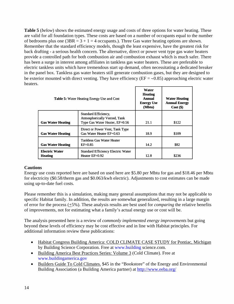
Table 5 (below) shows the estimated energy usage and costs of three options for water heating. These are valid for all foundation types. These costs are based on a number of occupants equal to the number of bedrooms plus one (3BR = 3 + 1 = 4 occupants.). Three Gas water heating options are shown. Remember that the standard efficiency models, though the least expensive, have the greatest risk for back drafting - a serious health concern. The alternative, direct or power vent type gas water heaters provide a controlled path for both combustion air and combustion exhaust which is much safer. There has been a surge in interest among affiliates in tankless gas water heaters. These are preferable to electric tankless units which have tremendous start up demand, often necessitating a dedicated breaker in the panel box. Tankless gas water heaters still generate combustion gases, but they are designed to be exterior mounted with direct venting. They have efficiency (EF = ∼0.85) approaching electric water heaters.
Cautions Energy use costs reported here are based on used here are $5.80 per Mbtu for gas and $18.46 per Mbtu for electricity ($0.58/therm gas and $0.063/kwh electric). Adjustments to cost estimates can be made using up-to-date fuel costs. Please remember this is a simulation, making many general assumptions that may not be applicable to specific Habitat family. In addition, the results are somewhat generalized, resulting in a large margin of error for the process (+5%). These analysis results are best used for comparing the relative benefits of improvements, not for estimating what a family’s actual energy use or cost will be. The analysis presented here is a review of commonly implemented energy improvements but going beyond these levels of efficiency may be cost effective and in line with Habitat principles. For additional information review these publications:
• Habitat Congress Building America: COLD CLIMATE CASE STUDY for Pontiac, Michigan by Building Science Corporation. Free at www.building science.com.
• Building America Best Practices Series: Volume 3 (Cold Climate). Free at www.buildingamerica.gov
• Builders Guide To Cold Climates. $45 in the “Bookstore” of the Energy and Environmental Building Association (a Building America partner) at http://www.eeba.org/
$23612.8Standard Efficiency Electric Water Heater EF=0.92
Electric Water Heating
$8214.2Tankless Gas Water Heater EF=0.85Gas Water Heating
$10918.9Direct or Power Vent, Tank Type Gas Water Heater EF=0.63Gas Water Heating
$12221.1
Standard Efficiency, Atmospherically Vented, Tank Type Gas Water Heater, EF=0.56Gas Water Heating
Water Heating Annual Energy
Cost ($)
Water Heating Annual
Energy Use (Mbtu)
Table 5: Water Heating Energy Use and Cost

15
ANALYSIS SUMMARY Regardless of foundation type, heating equipment improvements resulted in uniform savings (+2%). Envelope improvements resulted in small variations in amount of savings, as expected. Duct leakage had a much bigger impact on houses with ducts outside of the conditioned space (slab and vented crawlspace at 8% savings, others at 4-6%), as expected. Wall insulation savings ranged from a minimum of 6% savings on vented crawlspace or slab on grade houses (minimal wall area in conditioned space) to a maximum of 22% savings in a conditioned basement house. The total window and insulation package savings ranged from in a minimum savings of 11% in the vented crawlspace house and up to 30% in the unconditioned basement house, largely due to the wall insulation impact. Insulation As can be seen from the tables, one of the simplest and most cost effective ways of increasing Michigan housings’ energy efficiency is through increased wall insulation. The standard insulation was assumed to be R-13 in the above grade walls and R-5 in the crawlspace or basement walls. This level of insulation was observed in several affiliates’ construction methods. R-22 in the above grade walls is obtainable by using 2X6 wall construction, including R-19 insulation in the wall cavities, and adding rigid insulation such as Dow Blue Board to the exterior of the house. Basement and crawlspace wall insulation levels can be increased fairly easily. BAIHP staff observed many basement type houses using a product called the “Reward Wall System” for their basements. This product provides an R-5 insulation as a minimum, but insulation is easily added to the interior side of the system, allowing for R-19 or more in the basement walls. In a basement style houses, the analyzed wall insulation increase (R22 above grade walls and R-19 basement walls) results in a 19% - 22% decrease in heating costs. In houses with crawlspaces or slab on grade the increase is only 6-8%, still significant, and easily obtainable. These results are shown in Table 3. Combustion Safety and Air Sealing For combustion safety reasons, all houses heated or provided hot water by gas should use power vent or direct vent equipment. This equipment is also more efficient, often paying for itself over the life of the equipment by reducing energy expenditures. However, the greater concern is the potential for combustion by-products, the worst of which is CO, entering the conditioned area through some combination of events that cause the house to go to a negative pressure with respect to the outside and back-drafting the unit. Habitat houses are most often built very tightly; volunteers understand the idea and pursue air sealing with great zeal. Although air sealing in heating climates saves significant energy, it makes the house more susceptible to these negative pressure events. Consider trying to blow up a leaky balloon -- nothing happens until most of the leaks are sealed. Of particular note are houses with sealed crawlspaces or basements with gas equipment. These houses should not have their floor plane sealed without insuring that the duct system is sized correctly and not leaking. Most often these houses have good doors or hatch covers that seal well. The only current path for pressure relief is the leaky floor plane. Thus air tightening the conditioned space should only be undertaken after combustion safety issues are under control. After that, an air tightening strategy is an excellent strategy for improving energy efficiency, durability, and comfort. Duct Sealing Another inexpensive method of saving energy is to build tighter duct work. The current use of building cavities, like floor joist cavities and interior wall cavities, for air ducts results in leaky ducts that are very hard to seal. Duct leakage has a large impact when any of the duct work is outside the conditioned envelope, like the attic or a vented crawlspace. When the duct work is in a basement or

16
sealed crawlspace (inside the conditioned space) the effect is somewhat diminished but still can cause problems. As a method of heating basements it works, but it is crude and can cause problems with moisture damage and early equipment failure at best, and severe health risks (due to consequent air pressure imbalances) including death at worst (see Combustion Safety Appliance Safety above). While tight duct work saves energy and money it can have safety impacts outlined in the “Duct Leakage Concepts” and “Combustion Safety” portions of this document, and must be undertaken with forethought and care. Take care to avoid any significant pressures generated in the house by unbalanced duct leakage or door closures. These result in infiltration of outside air with its attendant risks, outlined above. RECOMMENDATIONS • Use high efficiency gas furnaces (AFUE > 90%) and direct vent or power vent water heaters rather
than atmospherically vented ones. Not only are they more energy efficient, they eliminate any health and safety concerns about combustion by-products.
• Provide a barometrically activated fresh air inlet into the area the furnace is located to provide makeup air in the event of accidental depressurization in the combustion area.
• Build above grade walls with a minimum of R-19. Basement and crawlspace wall insulation should also be increased. ICF blocks have been used successfully by several affiliates in the area, providing an R-14 basement wall. Systems like the “Reward Wall System” can result in an R-24 basement wall when their R-5 outer layer of insulation is augmented with R-19 batt insulation.
• Attic insulation levels above R-30 and Low-E windows provide smaller savings than equipment efficiency increases and wall insulation increases and should only be pursued after equipment and wall insulation upgrades have been made.
• Build properly sized, sealed, air tight duct systems using mastic and fiberglass mesh (instead of tape) to seal joints. Do not use unducted building cavities (panned floor joists, wall cavities, etc.) for air distribution systems. These systems all leak, are very difficult to seal well, and promote rot.
• Make sure that return grills and ducts are sized for the air flow rate of your system. For passive (unducted) return air paths, provide one square inch of return area for every 10 cfm of supply air.
• Consider a high efficiency, tankless, instantaneous gas hot water heater. They save floor space and energy compared to a gas tank water heater, as well as provide endless hot water. They have been incorporated into forced air systems to provide heat, as well as hot water.
• Install a hard wired carbon monoxide sensor with battery backup in the main body of any house whenever there is a gas furnace, gas water heater or attached garage in the house.
• Provide exhaust fans in bathroom and kitchen and operating guidelines for moisture control • After atmospherically vented gas furnaces and water heaters have been eliminated, reduce whole
house infiltration by making the air barrier (e.g. house wrap, rigid insulation, or exterior sheathing) separating conditioned space from outside continuous air tight – seal all holes created for wiring and plumbing, seal air barrier at edges and seams.
• Make sure that there is a continuous drainage plane behind exterior finishes (except stucco which is face-sealed)
• Provide a vapor retarder over ground in crawlspaces and under slabs (also acts a a capillary break) • Have heating and cooling equipment sized with industry standard sizing calculation such as the Air
Conditioner Contractors of America’s Manual J calculation.

17
CONTACTS FOR MORE INFORMATION AND TECHNICAL ASSISTANCE Habitat affiliates may request detailed technical assistance from Building America using the Partnership Invitation included at the end of this report. Please address questions about the material in this document to: Janet McIlvaine BAIHP / HFH Liaison 321-638-1434 [email protected]
David Beal BAIHP Research Analyst 321-638-1433 [email protected].
When sending email, please include the word “Habitat” in the subject line. More information about Building America’s partnership with Habitat for Humanity and other builders is available on line at www.buildingamerica.gov on the “Affordable Housing Research” page.

18
REFERENCES Cummings, J. B., J .J. Tooley, N. A. Moyer. Investigation of Air Distribution System Leakage and Its
Impact in Central Florida Homes. Contract Report, Florida Solar Energy Center, Cocoa, FL, FSEC-CR-397-91.
Cummings, J. B., J. J. Tooley, N. A. Moyer, Duct Doctoring; Diagnosis and Repair of Duct System
Leaks, DRAFT, Florida Solar Energy Center, Cocoa, Florida, May 1993. Davis, B. E., The Impacts of Air Distribution System Leakage on Heating Energy Consumption in
Arkansas Homes. Report submitted to the Arkansas Energy Office, 1991. Evans, Richard A., and Robert J. Tsal. “Basic Tips for Duct Design”, ASHRAE Journal, July 1996. Manclark, Bruce, and Bob Davis. “Duct Improvement in the Northwest, Part II: Mobile Homes.”
Home Energy Magazine, January/February 1996.

19
Partnership with the U.S. Department of Energy’s Building America Program All Habitat for Humanity affiliates are invited to participate in the U.S. Department of Energy’s Building America program. Affiliates may request building science and energy information, by contacting Janet McIlvaine at 321-638-1434 or via email at [email protected], please include Habitat in your subject line. Habitat for Humanity affiliates who already meet Energy Star may request technical assistance to strive for a higher level of energy efficiency that is still cost effective, volunteer friendly, reliable, and maintainable. Recommendations will include improvements related to equipment and appliance efficiency and reductions in heating and cooling loads. Affiliates who meet qualifications outlined below will receive an individual technical assistance review and evaluation. When possible, this will include free blower door and duct leakage testing. If your affiliate meets the criteria below, complete this page and return to:
Janet McIlvaine Building America liaison to Habitat for Humanity FAX: 321-638-1439 Mail: 1679 Clearlake Road, Cocoa, FL 32922 Email: [email protected] (please include “Habitat” in your subject line)
Qualifications for receiving an individual technical assistance review:
1. Completed items 1-3 items under “Core Capacity” on the Construction Capacity Indicators checklist, see page 2 of this document.
2. Desire to address, in process of addressing, or already completed items 4-8. 3. Build at least 5 homes per year. 4. Have approval to seek this technical assistance from the following:
(Note: attach business cards or complete info and sign) Executive Director Name: ___________________________ Phone: __________________________ Email: ___________________________ Signature:________________________ Construction Manager: Name: ___________________________ Phone:___________________________ Email:___________________________ Signature:________________________
President of the Board, with approval Name: __________________________ Phone:___________________________ Email:___________________________ Signature:________________________ Building Committee Chair, with approval Name: __________________________ Phone:___________________________ Email:___________________________ Signature:________________________

20
Construction Capacity Indicators
This document is a tool to assess the construction capacity characteristics of Habitat for Humanity affiliates. It breaks down construction operations into main categories and lists capacity indicators for three stages of affiliate growth. These indicators are intended to be guidelines for self-assessment by affiliate leaders interested in growing the capacity of their affiliate’s construction operations.
Core Capacity □ 1. Basic House Description approved by affiliate Board of Directors / construction
committee.
□ 2. Houses comply with all local building codes or 2000 International Residential Code.
□ 3. Houses comply with HFHI House Design Criteria.
□ 4. Site construction complies with HFHI model Safety Policy. □ 5. Houses meet standards for healthy indoor ventilation.
□ 6. Houses meet standards for moisture control. □ 7. Houses meet or exceed Energy Star or equivalent program ratings.
□ 8. New houses built in high risk zones include active radon mitigation systems. NOTE: This checklist of Core Capacity Indicators is excerpted from a longer list of Construction Capacity Indicators developed by the Habitat for Humanity International Department of Construction and Environmental Resources. This checklist is used here by permission from Russ Griffith, U.S. Construction Specialist in that Department. The numbers (1-8) were added for ease of discussion. For more information on the complete list, contact Russ Griffith at 615 403 4956 or via email at [email protected].