Embed Size (px)
Citation preview
Energy Design UpdateThe Monthly Newsletter on Energy-Effi cient Housing
VOL. 34, NO. 6 • JUNE 2014
IN DEPTH
Good Intentions, Unintended Consequences
Florida Retrofi t Challenge Mechanical Standard Offers Perspective and Lessons on Raising the Bar for Retrofi t Codes (Part One)
On the surface, subjecting existing homes to the same standards as new homes looks like a good idea. But focusing on numeric results and effi ciency specifi cations without facing the reality of fi eld conditions only tells one part of the story.
Janet McIlvaine, Senior Researcher at Florida Solar Energy Center (FSEC), and others, see a serious performance gap, especially when examining an aging housing population in the Southern US; one heavily populated by starts from the 1970’s through the 1990’s. To address this divide, the Building AmericaSM Partnership for Improved Residential Construction (BA-PIRC), led by FSEC, launched Th e Retrofi t Challenge Initiative. Th is Initiative is currently focused on aff ordable housing pro-grams conducting whole house renovations. Th e Retrofi t Challenge selects key build-ing science principles commonly seen in new homes for occupant health and safety, building durability, and thermal comfort and targets these best practices toward ret-rofi ts. Th e Retrofi t Challenge’s Best Practices Checklist (http://www.ba-pirc.org/retro-fi t) was compiled after a 4-year study that completed 70 comprehensive aff ordable housing renovations. (For more on the Challenge, see Energy Design Update, March 2014, In Practice, “How Do We Solve A Problem Like Retrofi t Performance?”)
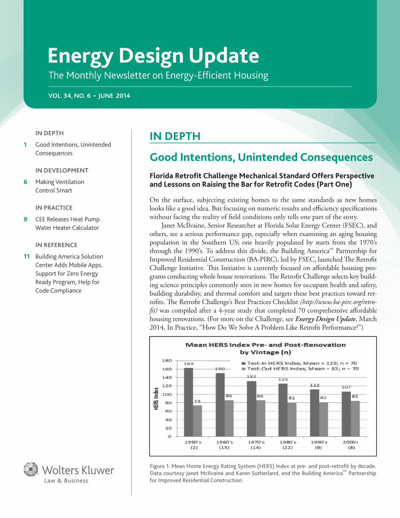
Figure 1. Mean Home Energy Rating System (HERS) Index at pre- and post-retrofi t by decade.
Data courtesy Janet McIlvaine and Karen Sutherland, and the Building AmericaSM
Partnership
for Improved Residential Construction.
IN DEPTH
1 Good Intentions, Unintended
Consequences
IN DEVELOPMENT
6 Making Ventilation
Control Smart
IN PRACTICE
9 CEE Releases Heat Pump
Water Heater Calculator
IN REFERENCE
11 Building America Solution
Center Adds Mobile Apps,
Support for Zero Energy
Ready Program, Help for
Code Compliance
2 ENERGY DESIGN UPDATE®
Energy Design UpdateEditor
Amanda Voss
Designer
Chris Tankiewicz
Energy Design Update (ISSN 0741-3629) is published monthly by Aspen Publishers, 76 Ninth Avenue, New York, NY 10011. (212) 771-0600. One-year subscription costs $595. To subscribe, call 1-800-638-8437. For customer service, call 1-800-234-1660. POSTMASTER: Send address changes to Energy Design Update, Aspen Publishers, 7201 McKinney Circle, Frederick, MD 21704. Permission requests: For information on how to obtain permission to reproduce content, please go to the Aspen Publishers website at www.aspenpublishers.com/permissions. Printed in the U.S.A.
© 2014 CCH Incorporated. All Rights Reserved.
Purchasing reprints: For customized article reprints, please contact Wright’s Media at (877) 652-5295 or go to the Wright’s Media website at www.wrightsmedia.com.
Editor’s Contact Information: Amanda Voss, Energy Design Update, 9019 Hunters Creek Street, Highlands Ranch, CO 80126, 303-663-2009, [email protected].
Energy Design Update is designed to provide accurate and authoritative information in regard to the subject matter covered. It is sold with the understanding that the publisher is not engaged in rendering legal, accounting, or other professional service. If legal advice or other expert assistance is required, the services of a competent professional person should be sought. —From a declaration of Principles jointly adopted by a Committee of the American Bar Association and a Committee of Publishers.
To date, the Retrofi t Challenge fi eld study has seen some great wins: A key fi nding was that by applying an analogous set of replacement specifi cations, effi ciency enhancements, and systems engineering strategies, similar post-retrofi t whole house effi ciencies were achieved in homes of widely disparate pre-retrofi t effi ciencies (see Figure 1). On average, the homes in the study posted a Home Energy Rating System (HERS) Index score improvement of 34%. Th e average HERS Index score was 83 – similar to Florida homes built from 2000 to 2010. In es-sence, Florida homes from the 60’s and older can be made “as good as new,” at least from a whole house effi ciency perspective.
Mechanical system improvements played a major role in this whole house effi ciency improvement. For example, the average SEER Equipment Effi ciency increase seen was 49%. Heating effi ciency, though less important in Florida than in other parts of the country, rose radically as well. Eighteen of the 20 homes with electric resistance heating were retrofi tted with heat pumps. Duct air tightness improved also with 75% of the homes achieving test results on par with the Energy Star for New Homes Standard Version 2 in force at the time of the study in 2009-11.
Retrofi t Challenge measures are experiencing perfor-mance success in the fi eld. Yet the burgeoning promise of “old as new again” performance must meet the harsh reality of code and existing home conditions. Th ese things often result in troublesome consequences, despite the best of intentions.
Mechanical Systems Pinpoint Code Divide
“Our starting point for evaluating mechanical system re-placement recommendations for the Retrofi t Challenge was our Building America experience with high performance new homes and Florida’s new construction building codes,” said McIlvaine. “Th e Florida Building Commission has really done a good job of slowly integrating proven building sci-ence strategies into the code over the past 20 years backed by extensive research and practical experience.”
For example, the Florida Building Code for new homes requires sealed return plenums, bans the use of building cavities for air distribution, and requires passive return air pathways from bedrooms. New homes also must adhere to Manual J sizing and air handlers must be installed to have 4” or more clearance on all sides for access and sealing.
“Yet these requirements do not apply to HVAC change-outs,” McIlvaine stated. “It makes for a bit of a double standard. If it’s right and reasonable for new homes, why isn’t the same standard there for existing homes? Th e dif-ferences contribute signifi cantly to the energy effi ciency and performance of existing homes when compared to new ones.”
Under the Florida Building Code, standards set for replacement heating, ventilation, and air-conditioning (HVAC) equipment are minimal. Contractors are required to leave replacement equipment in a condition that is equiva-lent to what was originally approved at the time of the fi rst installation. “So if a house was built before codes were insti-tuted, or the HVAC system was retrofi tted, there are essen-tially no requirements, which results in basically an anything goes approach.”
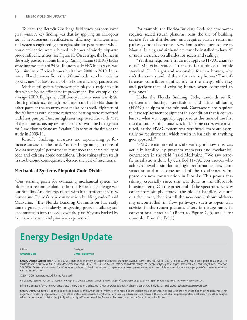
“FSEC encountered a wide variety of how this was actually handled by program managers and mechanical contractors in the field,” said McIlvaine. “We saw retro-fit installations done by certified HVAC contractors who achieved results similar to high performance new con-struction and met some or all of the requirements im-posed on new construction in Florida. This proves fea-sibility, especially since this was done in the affordable housing arena. On the other end of the spectrum, we saw contractors simply remove the old air handler, vacuum out the closet, then install the new one without address-ing uncontrolled air flow pathways, such as open wall cavities in the return plenum. There is a huge range in conventional practice.” (Refer to Figure 2, 3, and 4 for examples from the field.)

JUNE 2014 3
For subscriptions call 1.800.638.8437 or visit our Web site at aspenpublishers.com
Th e vagueness of retrofi t accountability also means that contractors doing a high quality job must compete with low quality installations in a market where the consumer doesn’t have the information to diff erentiate between levels of quality. “Consumers don’t even know they have a choice,” McIlvaine said. “If certain quality guidelines were instituted into the me-chanical code for existing homes, it would bring the competi-tion more in line. Th e contractors achieving high performance levels wouldn’t be cutting themselves short to compete.”
Implications of Mandating New Construction Standards Hit Home
“Th at said, there are quite a few reasons that mandating any new requirements for retrofi ts sounds good conceptually but may actually lead to major problems,” McIlvaine stated.
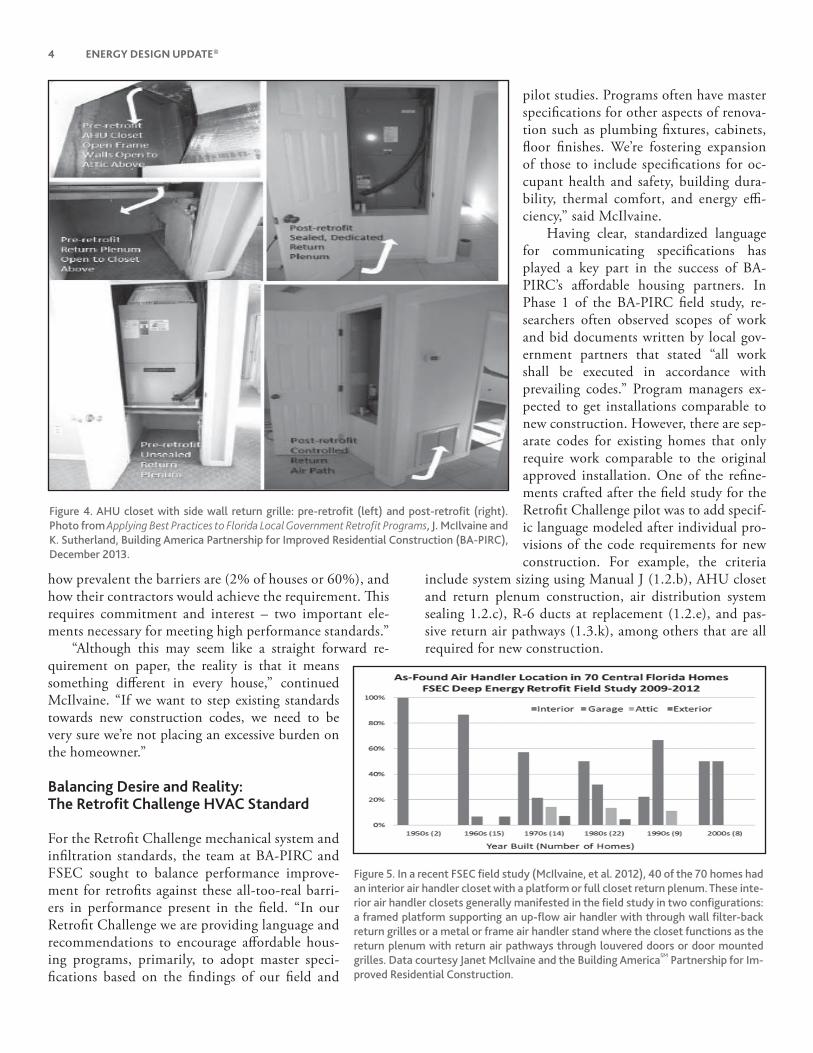
Focusing on mechanical system requirements, consider the following relevant characteristics: the vast majority of Florida homes have central cooling with central returns, rather than fully ducted returns. In Florida, almost all homes are either slab-on-grade construction, or have a small crawlspace. Th ere are vir-tually no basements. Th e primary location for an air handler is either within the conditioned space in an interior closet with a central return, or, in newer construction, in the garage. Orches-trating a mechanical system change-out means dealing with fac-tors already set in stone, like placement of ductwork, air handler closet (AHC), and return locations (see Figure 5).
“If you demand that new construction mechanical sys-tem requirements be met in every existing home, you could be in for real trouble and expense,” stressed McIlvaine. Man-dating the AHC clearances around the air handler found in new construction would mean moving entire walls and ad-justing ductwork in certain existing homes. Th is represents a greater cost and increased scope of work outside of the me-chanical contractor’s range, as well as a fi nancial burden and much higher “hassle factor” for the consumer.
“For one house in a related FSEC fi eld study funded by the Florida Code Commission, in order to enlarge the existing air handling closet so that we could increase clear-ance for sealing, the homeowner either had to lose about
1/3 of their master bedroom closet or move the main electrical pan-el,” McIlvaine said. “Changing out heating and cooling components already means a major fi nancial investment for the homeowner. Adding an entire renovation to that picture rules out the possibil-ity of replacement for many.”
Th e ultimate lesson in practi-cality from the fi eld study? “When we look at requiring a measure as part of a renovation program, we need to quantify the cost and im-provement, and look at an array of solutions that contractors are already using. Th is is a step in un-derstanding the implications of our decision,” McIlvaine summa-rized. “For example, if a program requires sealing return plenums (see Figures 6 and 7), which is one of the best practices, program managers need to know what the major barriers are to achieving it,
Figure 2. Framed or “platform” return air plenum in an air handler clos-
et in the conditioned space. Plenum had no air barrier, thereby con-
necting it to the walls and attic, and had dirt, debris, and fi berglass in
the space. Photo courtesy Janet McIlvaine and the Building AmericaSM
Partnership for Improved Residential Construction.
Figure 3. Pre-retrofi t metal AHU stand with no dedicated return air path (left); post-retrofi t platform
AHU support with dedicated, mastic sealed return air path (right). Photo from Applying Best Practices to Florida Local Government Retrofi t Programs, J. McIlvaine and K. Sutherland, Building America Partner-
ship for Improved Residential Construction (BA-PIRC), December 2013.
4 ENERGY DESIGN UPDATE®
Figure 4. AHU closet with side wall return grille: pre-retrofi t (left) and post-retrofi t (right).
Photo from Applying Best Practices to Florida Local Government Retrofi t Programs, J. McIlvaine and
K. Sutherland, Building America Partnership for Improved Residential Construction (BA-PIRC),
December 2013.
how prevalent the barriers are (2% of houses or 60%), and how their contractors would achieve the requirement. Th is requires commitment and interest – two important ele-ments necessary for meeting high performance standards.”
“Although this may seem like a straight forward re-quirement on paper, the reality is that it means something diff erent in every house,” continued McIlvaine. “If we want to step existing standards towards new construction codes, we need to be very sure we’re not placing an excessive burden on the homeowner.”
Balancing Desire and Reality: The Retrofi t Challenge HVAC Standard
For the Retrofi t Challenge mechanical system and infi ltration standards, the team at BA-PIRC and FSEC sought to balance performance improve-ment for retrofi ts against these all-too-real barri-ers in performance present in the fi eld. “In our Retrofi t Challenge we are providing language and recommendations to encourage aff ordable hous-ing programs, primarily, to adopt master speci-fi cations based on the fi ndings of our fi eld and
pilot studies. Programs often have master specifi cations for other aspects of renova-tion such as plumbing fi xtures, cabinets, fl oor fi nishes. We’re fostering expansion of those to include specifi cations for oc-cupant health and safety, building dura-bility, thermal comfort, and energy effi -ciency,” said McIlvaine.
Having clear, standardized language for communicating specifi cations has played a key part in the success of BA-PIRC’s aff ordable housing partners. In Phase 1 of the BA-PIRC fi eld study, re-searchers often observed scopes of work and bid documents written by local gov-ernment partners that stated “all work shall be executed in accordance with prevailing codes.” Program managers ex-pected to get installations comparable to new construction. However, there are sep-arate codes for existing homes that only require work comparable to the original approved installation. One of the refi ne-ments crafted after the fi eld study for the Retrofi t Challenge pilot was to add specif-ic language modeled after individual pro-visions of the code requirements for new construction. For example, the criteria
include system sizing using Manual J (1.2.b), AHU closet and return plenum construction, air distribution system sealing 1.2.c), R-6 ducts at replacement (1.2.e), and pas-sive return air pathways (1.3.k), among others that are all required for new construction.
Figure 5. In a recent FSEC fi eld study (McIlvaine, et al. 2012), 40 of the 70 homes had
an interior air handler closet with a platform or full closet return plenum. These inte-
rior air handler closets generally manifested in the fi eld study in two confi gurations:
a framed platform supporting an up-fl ow air handler with through wall fi lter-back
return grilles or a metal or frame air handler stand where the closet functions as the
return plenum with return air pathways through louvered doors or door mounted
grilles. Data courtesy Janet McIlvaine and the Building AmericaSM
Partnership for Im-
proved Residential Construction.

JUNE 2014 5
For subscriptions call 1.800.638.8437 or visit our Web site at aspenpublishers.com
Th e following is the list of HVAC and Whole House Air Tightness criteria for partner groups created by BA-PIRC based on the 70 house fi eld study and the Retrofi t Challenge pilot study:
1 Heating, Ventilation, Cooling, and Air Condition-ing (HVAC) Distribution Systems
(Caution: Refer to the Combustion Safety section (3.11) if a gas furnace exists or is planned.)
1.1 Existing HVAC Equipment Not Being Replaced a. Check/Service if needed: charge, condition of coils,
condensate lines, exhaust fl ues, combustion air supply, gas lines, and other components.1.2 Full or Partial HVAC System Replacement
b. ENERGY STAR heat pump c. ACCA Manual J calculations d. Seal accessible ducts e. Modify AHU closets to create sealed return plenum
with wall or ceiling return air grille f. Duct Replacement: Install new ducts with R-value ≥ 6 g. When equipment and ducts are replaced, relocate
AHU into conditioned space h. Perform ACCA Manual S equipment selection i. Perform ACCA Manual D duct sizing j. Produce a schematic duct design for fi eld crew k. Conduct rough-in inspection
1.3 All Homes Regardless of HVAC System Replace-ment a. Seal all duct connections in supply and return runs,
return plenum, connections to AHU. b. Conduct a duct airtightness test. c. Eliminate louvered doors that serve as returns. Elimi-
nate metal AHU stands. d. Install and seal an air barrier to separate return from
adjacent wall cavities. e. Provide partial door above return. f. Flex duct insulation covers all collar and boot
connections. g. Flex duct runs should not be kinked or have sharp bends.
h. Strap fl ex ducts to trusses every 5’. i. Install MERV 6 fi lter. j. Bathroom, kitchen exhaust fans and dryer ducted to outside. k. Verify Bedroom Return Air per guidelines in Florida
Mechanical Code Section 601.4.
I. Install a bath fan timer.
2 Whole-House Airtightness a. Ensure whole-house air leakage of 6 or less ACH at the
test pressure of 50 pascals (ACH50 ≤ 6.0). b. Seal common air infi ltration points with code-ap-
proved sealant.(Source: McIlvaine et al 2013.)
Rubber, Meet Road: Lessons from the Retrofi t Challenge
McIlvaine shared several key takeaways from the Retrofi t Challenge pilot program and fi eld studies:
Learn climate appropriate strategies – both the theory and implementation. If the reasoning behind a practice is not well understood, there is a risk that it will receive a lower priority or be ignored, possibly increasing risk. Do a few trial installations of unfamiliar details and strategies before mandating them.Develop clear, standardized language for communi-cating specifications and expectations to contractors and subcontractors and other program stakeholders. Clear communication is necessary to ensure that high performance specifi cations translate into high perfor-mance results.
Figure 6. Framed Return Plenum retrofi tted with ducted return air path
formed by duct board sealed on the air barrier (foil) side. Note sealant
at fl oor penetration. Photo courtesy Janet McIlvaine and the Building
America Partnership for Improved Residential Construction.
Figure 7. Detail for sealing the return plenum to the air handler. Im-
age from Building America Measure Guideline: Air Sealing Mechani-
cal Closets in Slab-On-Grade Homes, Bruce Dickson, February 2012.
6 ENERGY DESIGN UPDATE®
IN DEVELOPMENT
Making Ventilation Control Smart
A much-anticipated development in ventilation, Lawrence Berkeley National Laboratory’s (LBNL) Residential Integrat-ed Ventilation Controller (RIVEC) (http://homes.lbl.gov/proj-ects/rivec) will roll out later this year, becoming commercially available across the US.
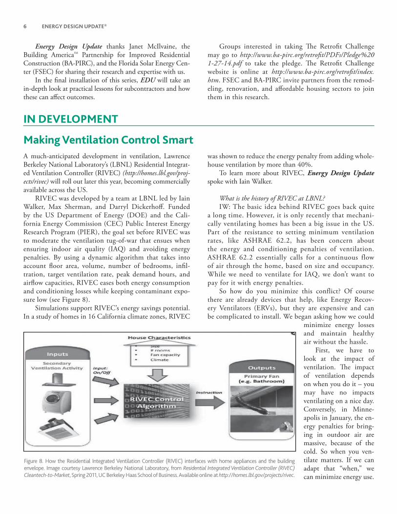
RIVEC was developed by a team at LBNL led by Iain Walker, Max Sherman, and Darryl Dickerhoff . Funded by the US Department of Energy (DOE) and the Cali-fornia Energy Commission (CEC) Public Interest Energy Research Program (PIER), the goal set before RIVEC was to moderate the ventilation tug-of-war that ensues when ensuring indoor air quality (IAQ) and avoiding energy penalties. By using a dynamic algorithm that takes into account fl oor area, volume, number of bedrooms, infi l-tration, target ventilation rate, peak demand hours, and airfl ow capacities, RIVEC eases both energy consumption and conditioning losses while keeping contaminant expo-sure low (see Figure 8).
Simulations support RIVEC’s energy savings potential. In a study of homes in 16 California climate zones, RIVEC
was shown to reduce the energy penalty from adding whole-house ventilation by more than 40%.
To learn more about RIVEC, Energy Design Update spoke with Iain Walker.
What is the history of RIVEC at LBNL?IW: The basic idea behind RIVEC goes back quite
a long time. However, it is only recently that mechani-cally ventilating homes has been a big issue in the US. Part of the resistance to setting minimum ventilation rates, like ASHRAE 62.2, has been concern about the energy and conditioning penalties of ventilation. ASHRAE 62.2 essentially calls for a continuous flow of air through the home, based on size and occupancy. While we need to ventilate for IAQ, we don’t want to pay for it with energy penalties.
So how do you minimize this conflict? Of course there are already devices that help, like Energy Recov-ery Ventilators (ERVs), but they are expensive and can be complicated to install. We began asking how we could
minimize energy losses and maintain healthy air without the hassle.
First, we have to look at the impact of ventilation. Th e impact of ventilation depends on when you do it – you may have no impacts ventilating on a nice day. Conversely, in Minne-apolis in January, the en-ergy penalties for bring-ing in outdoor air are massive, because of the cold. So when you ven-tilate matters. If we can adapt that “when,” we can minimize energy use.
Figure 8. How the Residential Integrated Ventilation Controller (RIVEC) interfaces with home appliances and the building
envelope. Image courtesy Lawrence Berkeley National Laboratory, from Residential Integrated Ventilation Controller (RIVEC)
Cleantech-to-Market, Spring 2011, UC Berkeley Haas School of Business. Available online at http://homes.lbl.gov/projects/rivec.
Energy Design Update thanks Janet McIlvaine, the Building AmericaSM Partnership for Improved Residential Construction (BA-PIRC), and the Florida Solar Energy Cen-ter (FSEC) for sharing their research and expertise with us.
In the fi nal installation of this series, EDU will take an in-depth look at practical lessons for subcontractors and how these can aff ect outcomes.
Groups interested in taking Th e Retrofi t Challenge may go to http://www.ba-pirc.org/retrofi t/PDFs/Pledge%201-27-14.pdf to take the pledge. Th e Retrofi t Challenge website is online at http://www.ba-pirc.org/retrofi t/index.htm. FSEC and BA-PIRC invite partners from the remod-eling, renovation, and aff ordable housing sectors to join them in this research.
JUNE 2014 7
For subscriptions call 1.800.638.8437 or visit our Web site at aspenpublishers.com
That brings us to our next research question: How do you change the time you ventilate, but still maintain adequate IAQ? This is the principle of equivalent venti-lation, or how ventilation changes with time to change pollutant levels. Because the concentration of pollut-ants is not proportional to the ventilation rate, you can’t simply average to estimate exposure. The equivalency calculations are used to integrate the effects of changing ventilation rates on the pollutants and compare that to the concentration of pollutants found using a continu-ous ventilation rate.
Th e main issue is to ventilate the smart way – fi gure out what things are moving air, shift the times to minimize energy impact, and integrate the fan with non-mechanical ventilation paths.
So equivalent ventilation is the foundational concept under-lying RIVEC’s calculations. What were your parameters when you developed the algorithm?
IW: Th e key thing is to create simple representations of the problem that allow you to do calculations on the fl y in the control system. One of the main things we wanted to capture in our control system was to ventilate when the energy penalty is the least. If we are in winter, what would the impact be if we turned the vent off from 4:00 a.m. to 8:00 a.m. when its colder, and instead ventilated more as the day warms up? How would ventilating in early morning hours during the summer look, both in terms of indoor conditioning and pollutant exposure? Th at was our “Mark 1” idea.
To support the added ventilation needed during more ideal weather conditions, we experimented with oversizing the system’s fan by 25%, to compensate for time off. Our equivalent ventilation calculations let us figure out the appropriate sizing that is needed. For ex-ample, if the system was off for 4 hours, then we need to have that fan running about 25% more when it is in operation to compensate.
In our “Mark 2” iteration, we began asking whether we could account for the air fl ows in the equivalency cal-culations from other fans in the house, such as kitchen, bathroom, and clothes dryer exhausts, and save even more energy. Th ese Mark 1 and 2 ideas were fi rst evaluated in work for the California Energy Commission.
Th at’s how we got started with smart ventilation.
What simulation and testing eff orts are underway? How has the system performed in the fi eld?
IW: Currently we are only evaluating RIVEC in research situations. We have a few tests in study homes, as well as ex-tensive simulation eff orts. Next year, we plan to expand the evaluations to include strategies to minimize humidity eff ects in humid climates.
We are currently working with Building America teams on a house outside of Chicago, Illinois to test temperature control strategies.
Trekking back to ASHRAE 62.2, the standard lets you take a credit for house leakage. We incorporated this leakage credit into RIVEC. By including this factor in the controller, the system can sense outside temperature
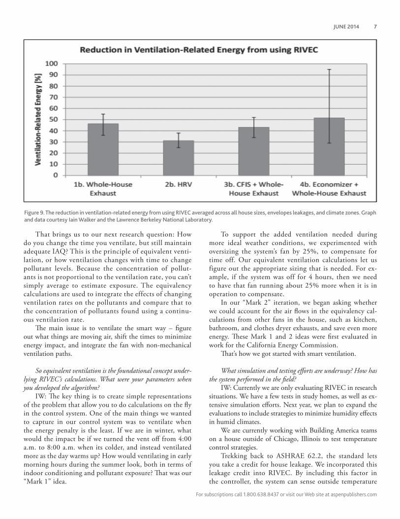
Figure 9. The reduction in ventilation-related energy from using RIVEC averaged across all house sizes, envelopes leakages, and climate zones. Graph
and data courtesy Iain Walker and the Lawrence Berkeley National Laboratory.
8 ENERGY DESIGN UPDATE®
and wind, and can estimate simple infiltration rates. If infiltration jumps, RIVEC can shut the mechanical fan off when it obtains enough fil-tration from leakage.
In testing we want to see confi rmation of our controls and algorithms. Th e meat and pota-toes is how it performs related to energy savings.
What benefi ts are you seeing from RIVEC? Did your hypothesis of energy savings hold up?
IW: Simulations demonstrate a 40% savings of ventilation related energy, which would equate to around a 5% to 10% energy savings from the whole house bill. Especially in a modern, high performance, energy effi cient home, ventilation is proportionally more important, so these fac-tors could go up (see Figure 9).
During peak periods, our research also indicates a 2kW peak load reduction for a typical home.
What can we expect as RIVEC comes to market later this year?
IW: The first generation of RIVEC will revolve around equivalent ventilation equations, making sure air is brought in efficiently while avoiding exceeding pollutant dose and exposure levels relative to a con-stantly operating fan. The control will operate based on time and sensors indicating which fans are on or off. Every few minutes the algorithm will weigh how much dilution there is from the current air flow and match that answer against the equation. RIVEC then makes the decision to turn on the whole house system based on dose and exposure. The concept of smart ventilation involves a bunch of things; however, it will always re-volve around equivalent ventilation calculations of dose and exposure.
What’s next for RIVEC?Since proofi ng our initial algorithm, we have looked at
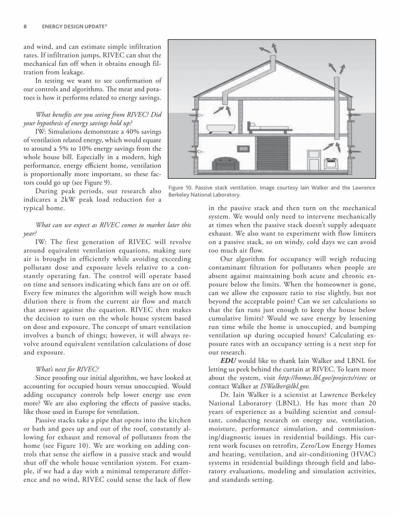
accounting for occupied hours versus unoccupied. Would adding occupancy controls help lower energy use even more? We are also exploring the eff ects of passive stacks, like those used in Europe for ventilation.
Passive stacks take a pipe that opens into the kitchen or bath and goes up and out of the roof, constantly al-lowing for exhaust and removal of pollutants from the home (see Figure 10). We are working on adding con-trols that sense the airflow in a passive stack and would shut off the whole house ventilation system. For exam-ple, if we had a day with a minimal temperature differ-ence and no wind, RIVEC could sense the lack of flow
in the passive stack and then turn on the mechanical system. We would only need to intervene mechanically at times when the passive stack doesn’t supply adequate exhaust. We also want to experiment with flow limiters on a passive stack, so on windy, cold days we can avoid too much air flow.
Our algorithm for occupancy will weigh reducing contaminant filtration for pollutants when people are absent against maintaining both acute and chronic ex-posure below the limits. When the homeowner is gone, can we allow the exposure ratio to rise slightly, but not beyond the acceptable point? Can we set calculations so that the fan runs just enough to keep the house below cumulative limits? Would we save energy by lessening run time while the home is unoccupied, and bumping ventilation up during occupied hours? Calculating ex-posure rates with an occupancy setting is a next step for our research.
EDU would like to thank Iain Walker and LBNL for letting us peek behind the curtain at RIVEC. To learn more about the system, visit http://homes.lbl.gov/projects/rivec or contact Walker at [email protected].
Dr. Iain Walker is a scientist at Lawrence Berkeley National Laboratory (LBNL). He has more than 20 years of experience as a building scientist and consul-tant, conducting research on energy use, ventilation, moisture, performance simulation, and commission-ing/diagnostic issues in residential buildings. His cur-rent work focuses on retrofits, Zero/Low Energy Homes and heating, ventilation, and air-conditioning (HVAC) systems in residential buildings through field and labo-ratory evaluations, modeling and simulation activities, and standards setting.
Figure 10. Passive stack ventilation. Image courtesy Iain Walker and the Lawrence
Berkeley National Laboratory.
JUNE 2014 9
For subscriptions call 1.800.638.8437 or visit our Web site at aspenpublishers.com
IN PRACTICE
CEE Releases Heat Pump Water Heater Calculator
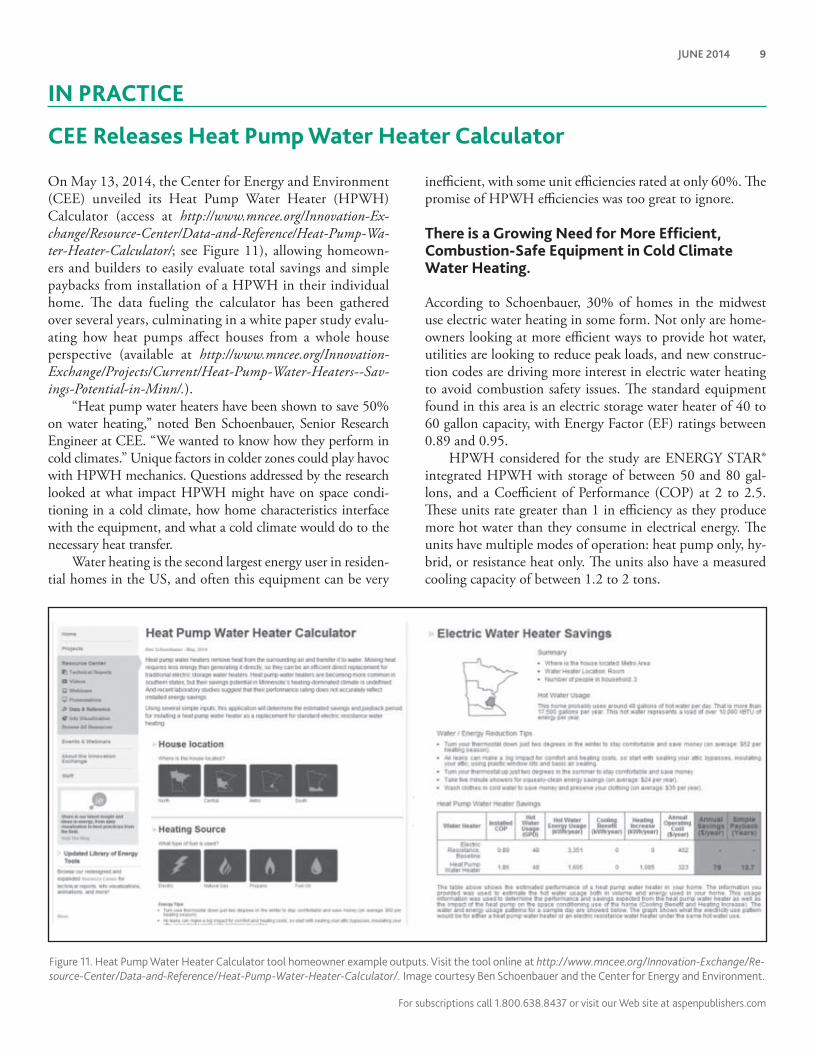
Figure 11. Heat Pump Water Heater Calculator tool homeowner example outputs. Visit the tool online at http://www.mncee.org/Innovation-Exchange/Re-
source-Center/Data-and-Reference/Heat-Pump-Water-Heater-Calculator/. Image courtesy Ben Schoenbauer and the Center for Energy and Environment.
On May 13, 2014, the Center for Energy and Environment (CEE) unveiled its Heat Pump Water Heater (HPWH) Calculator (access at http://www.mncee.org/Innovation-Ex-change/Resource-Center/Data-and-Reference/Heat-Pump-Wa-ter-Heater-Calculator/; see Figure 11), allowing homeown-ers and builders to easily evaluate total savings and simple paybacks from installation of a HPWH in their individual home. Th e data fueling the calculator has been gathered over several years, culminating in a white paper study evalu-ating how heat pumps aff ect houses from a whole house perspective (available at http://www.mncee.org/Innovation-Exchange/Projects/Current/Heat-Pump-Water-Heaters--Sav-ings-Potential-in-Minn/.).
“Heat pump water heaters have been shown to save 50% on water heating,” noted Ben Schoenbauer, Senior Research Engineer at CEE. “We wanted to know how they perform in cold climates.” Unique factors in colder zones could play havoc with HPWH mechanics. Questions addressed by the research looked at what impact HPWH might have on space condi-tioning in a cold climate, how home characteristics interface with the equipment, and what a cold climate would do to the necessary heat transfer.
Water heating is the second largest energy user in residen-tial homes in the US, and often this equipment can be very
ineffi cient, with some unit effi ciencies rated at only 60%. Th e promise of HPWH effi ciencies was too great to ignore.
There is a Growing Need for More Effi cient, Combustion-Safe Equipment in Cold Climate Water Heating.
According to Schoenbauer, 30% of homes in the midwest use electric water heating in some form. Not only are home-owners looking at more effi cient ways to provide hot water, utilities are looking to reduce peak loads, and new construc-tion codes are driving more interest in electric water heating to avoid combustion safety issues. Th e standard equipment found in this area is an electric storage water heater of 40 to 60 gallon capacity, with Energy Factor (EF) ratings between 0.89 and 0.95.
HPWH considered for the study are ENERGY STAR® integrated HPWH with storage of between 50 and 80 gal-lons, and a Coeffi cient of Performance (COP) at 2 to 2.5. Th ese units rate greater than 1 in effi ciency as they produce more hot water than they consume in electrical energy. Th e units have multiple modes of operation: heat pump only, hy-brid, or resistance heat only. Th e units also have a measured cooling capacity of between 1.2 to 2 tons.

10 ENERGY DESIGN UPDATE®
Figure 12. Best and worst case energy penalty simulation results from
heat pump water heaters in cold climates, measured in dollar costs. Image
courtesy Ben Schoenbauer and the Center for Energy and Environment.
Figure 13. Coeffi cient of Performance (COP) for electric water heaters: resistance electric compared to heat pump water heaters, based on daily hot
water usage in gallons. Image courtesy Ben Schoenbauer and the Center for Energy and Environment.
Are We Losing Space Conditioning for Gains in Water Heating Effi ciency?
Using HPWH in cold climate zones, despite the equipment ef-fi ciencies, raises a number of concerns. What is the impact of HPWH on the space conditioning load? Is there an impact from cooler ambient temperatures on HPWH effi ciency and capacity?
Typically, water heaters in Minnesota are installed in the basement, which is considered an unconditioned or partially conditioned mechanical space. Temperatures in these spaces can range from 50 to 60°F. In 2011, Steven Winter Associ-
ates, Inc., issued a measure guideline for the performance of HPWH in HP mode only. At lower temperatures, where the average ambient temperature is 50°F, performance is lower than when the ambient temperature is near 80°F.
“If the heat pump water heater is in 50°F air and is produc-ing 50 gallons of hot water daily, its COP is at 2; if you bump that temperature to 80°F, the COP goes to 3,” stated Schoenbauer.
However, relocating HPWH into the kitchen or next to the living room, while introducing them to warmer air, has other impacts. A signifi cant one to consider is the heat transfer impact of a HPWH. Th e effi ciency of a HPWH is achieved by pulling heat out of the surrounding air and putting it di-rectly into the water supply. In a cold climate, if a HPWH is installed in a conditioned space, those stolen BTU’s must be replaced to maintain overall space conditioning, especially during heating season. Simply put, the HPWH has a heating penalty in the winter and a cooling benefi t in the summer.
Although HPWH can produce signifi cant cooling ben-efi ts – lab data shows HPWH delivery of 1 ton of cooling for production of 50 gallons of hot water per day – these benefi ts are minimal in northern climate zones.
Th e CEE team saw a best case scenario of a $10 increase in heating bills, if HPWH were installed within the conditioned envelope in a northern climate zone home. In the worst case, homes experience a heating penalty of $200 per year. Th is was especially true in homes with ineffi cient heating equipment and HPWH installed in a main living space (see Figure 12).
“You can minimize impacts by looking at installing HPWH in unfi nished basements and by having effi cient heating, ventilating, and air conditioning (HVAC)systems,” Schoenbauer said.“Th e question for us became how to char-acterize these losses and benefi ts accurately? Not only did we need to weigh the equipment in the house used for space heating, but also its effi ciency and set points.”

JUNE 2014 11
For subscriptions call 1.800.638.8437 or visit our Web site at aspenpublishers.com
HPWH Effi ciencies Justify Their Use in Most Homes, Despite Climate Zone Impacts.
Despite the challenges presented by cold climates, just chang-ing water equipment effi ciencies from a COP of 0.9 to 2 equals $250 per year in savings for a house using 60 gallons of hot water per day. Th is equates to a 3 to 6 year simple payback for HPWH.
Calculating actual savings is more complex. Th is num-ber is based on installed location, ambient temperatures, the impact on space heating load, and how much domestic hot water (DHW) is used.
Daily hot water usage can dramatically alter savings pro-fi les. For very low water usage, electric resistance and HPWH units perform much the same; above 15 gallons a day usage, HPWH provide great benefi ts. Yet this effi cient eff ect is re-duced at high usage rates, beyond 100 gallons per day. Ac-cording to Schoenbauer, a HPWH peaks in performance at 20 to 40 gallons daily DHW usage (see Figure 13).
Despite heating energy penalties, the CEE team found that in the average Minnesota home, HPWH still make sense, and in most situations, result in an overall energy sav-ings. HPWHs are not recommended in situations where they will be installed in occupied space or where the removed heat will be made up, i.e., where a thermostat controls.
Taking Accumulated Data Into the CEE Calculator Offers an Individualized Picture of HPWH Performance.
Actual savings is derived from balancing positive and nega-tive impacts from the equipment. Taking aggregated simula-tion and fi eld data, CEE developed the Heat Pump Water Heater Calculator, allowing builders and retrofi tters to weigh whether or not HPWH make sense in an individual home. Th e Calculator takes into consideration home location, home heating source, equipment effi ciency, home cooling source, frequency of cooling demand, water heater location, number of people in the household, and energy costs. It then projects expected energy savings for the home if a HPWH is installed.
Th e Calculator also off ers simple payback information. HPWH are more expensive, and though more durable in the long run, can require plumbing modifi cations and new
ducting when installed. According to the National Renew-able Energy Laboratory (NREL), installed costs for HPWH are between $1400 to $2600; for electric resistance tanks the installed costs are $400 to $800.
Beyond individual homes, CEE is developing a Calcula-tor for utilities to weigh benefi ts of HPWH adoption on peak load energy consumption. A HPWH at maximum draw uses 600 watts as compared to the 4000 watts or more used by electric resistance units. Outputs from the utility calculator will provide savings per day estimates as well as peak load im-pacts. In addition to HPWH, CEE will incorporate datas on electrical thermal storage water heater strategies, which heat water at off peak times, another method to reduce peak loads. Th ese savings factors can be used to evaluate utility incentive and rebate programs.
Upcoming Research Will Evaluate Alternate Ways to Maximize HPWH.
Research teams within Building America are looking at several new ways to increase savings with HPWH, including optimiz-ing HPWH for thermal storage. Th is method would run heat pumps to overheat the tank during the night, minimizing or alleviating the need for the unit to operate during the day.
Other research eff orts will look into ducting and mechani-cal ventilation. Can a HPWH be linked with mechanical venti-lation in the home? Could it be planned to capture waste heat in a home, and integrated with a mechanical room or bathroom?
Th e Northwest Energy Effi ciency Alliance (NEEA) is also releasing new water heater ratings which may impact set-points. NEEA developed cold climate specifi cations for HPWH testing at colder ambient conditions. Work from NEEA has helped to drive manufacturers to look at cold climate impacts for HPWH.
Energy Design Update thanks Ben Schoenbauer, Senior Research Engineer at CEE, and the Center for Energy and Environment. Access the calculator online at http://mncee.org/Innovation-Exchange/Resource-Center/Data-and-Reference/Heat-Pump-Water-Heater-Calculator/. To view Schoenbauer’s latest presentation, “Quantifying Energy Savings from Heat Pump Water Heaters in Cold Climates,” go to http://www.mncee.org/Innovation-Exchange/Resource-Center/Webinars/Quantifying-Energy-Savings-from-Heat-Pump-Water-He/.
IN REFERENCE
Building America Solution Center Adds Mobile Apps, Support for Zero Energy Ready Program, Help for Code ComplianceSpearheaded by the Pacifi c Northwest National Laboratory (PNNL), the Building America Solution Center launched Building America Solutions, new mobile applications for
Android and Apple programs. Th e apps were developed to render the Solution Center more customizable and acces-sible. Registered users of the Solution Center can organize
Wolters Kluwer Law & Business connects legal and business communities with timely, specialized expertise and information-enabled solutions to
support productivity, accuracy and mobility. Serving customers worldwide, our products include those under the Aspen, CCH, ftwilliam, Kluwer Law
International, LoislawConnect, MediRegs, and TAGData names.
For subscriptions call 1.800.638.8437 or visit our Web site at aspenpublishers.com
12 ENERGY DESIGN UPDATE APRIL 2014
JUNE/9900520539
relevant content into customized Field Kits. Th e Solutions app then synchronizes Field Kits to a mobile device with the push of a button. Once synchronized, users can access their customized content anytime, anywhere, with or without cell or Wi-Fi coverage.
“Th e key here is that users can take valuable, project-specifi c knowledge easily into the fi eld, organized by their preference. We want this content accessible at any jobsite,” noted Michael Baechler, Senior Program Manager, PNNL.
Solution Center content includes guides on topics from advanced framing, to installation of ducts and insulation, and over 125 specifi c measures for constructing high-perfor-mance, energy-effi cient buildings.
Th e Solutions mobile app is available for Android tablets and smart phones running Android 4.0 or higher, and for iPad and iPhone devices running iOS 7.0 or higher. Android users can download the installer from https://basc.pnnl.gov/solutions, and iOS users can download from the Apple App Store using the search words: “Building America Solutions.”
In addition to making the Solution Center mobile, PNNL has added a live checklist to help builders work with the De-partment of Energy’s (DOE) Zero Energy Ready Home pro-gram. Th e Solution Center checklist will match the program checklist at each step, and includes provisions for pertinent parts of the Environmental Protection Agency’s Indoor air-PLUS and WaterSense programs. Beyond the checklist, the Solution Center also off ers technical and installation support for the programs. Th e Solution Center already provides tech-nical support for ENERGY STAR® for new homes program.
“Th e exciting thing here is not only that we now have Zero Energy Ready Home structure and content, we also have a lot of content for associated programs, like Indoor air-PLUS,” said Baechler. “Where we’re headed is, by Fall 2014, we will build out checklists for these associated programs. We will be able to off er the builder a truly comprehensive site in terms of subject matter and support programs.”
To visit the Building America Solution Center online, go to https://basc.energy.gov.
Launching in June 2014, Building America is taking aim at barriers to innovations from codes. Building America (BA) will release Code Compliance Briefs to facilitate the conver-sation between builders, installers, and code offi cials when an innovative product or technique is used in the fi eld. Th e new content will reside under the Compliance Tab in the Building America Solution Center labeled “Code Compliance Brief.”
Th e BA Guidance for Identifying and Overcoming Code, Standard, and Rating Method Barriers will be used as the baseline for determining if existing or new measure guides for the Building America Solution Center have a barrier. Resolv-ing Code and Standard Barriers to Building America Innova-tions (CSI) barriers are defi ned as any requirement in a code, standard, or rating method that:1. requires the wrong thing,2. prohibits the BA innovation,3. discourages a BA innovation, or4. does not encourage a BA innovation that would lead to
better, more effi cient homes.Th e intent for Code Compliance Briefs is to provide
additional information to help assure the measure will be deemed in acceptance with the code or standard. Briefs will include notes for codes offi cials on how to plan review and fi eld inspect and can also help the builder or remodeler with the proposed designs and provide the jurisdiction with infor-mation for acceptance. As part of the CSI eff orts, the need was identifi ed to develop additional guidance to builders, re-modelers, and code offi cials through the Building America Solution Center measure guidelines.
“We already see a fair amount of traffi c on the Building America Solution Center from code offi cials,” stated Michael Baechler, Senior Program Manager at Pacifi c Northwest Na-tional Laboratory (PNNL). “At the same time, however, we want code offi cials to understand innovations coming out of Building America research programs. If code offi cials can’t understand it and installers can’t understand what innova-tions are, that’s a barrier to them being implemented.”
By providing the same information to all interested par-ties, the Solution Center hopes for increased compliance and fewer innovations being questioned at the time of plan review and fi eld inspection.
“Code compliance briefs will focus on targeted technolo-gies and provide bite-sized information on that product. Th e briefs are focused to provide a builder with information be-fore a code offi cial, and to feel confi dent talking about the innovation. Th e verbiage is compatible with offi cial code lan-guage, and is written to provide information on how to per-form a fi eld evaluation of the innovation,” Baechler added.
Two briefs have already been developed and can be viewed at the following links: https://basc.pnnl.gov/code-compliance/double-wall-framing-code-compliance-brief, https://basc.pnnl.gov/code-compliance/bathroom-fan-ratings-code-compliance-brief.