Embed Size (px)
Citation preview
7/26/2019 Hollow Core Concrete DetailingManual
http://slidepdf.com/reader/full/hollow-core-concrete-detailingmanual 1/41
7/26/2019 Hollow Core Concrete DetailingManual
http://slidepdf.com/reader/full/hollow-core-concrete-detailingmanual 2/41
Hollow Core
Concrete Pty Ltd
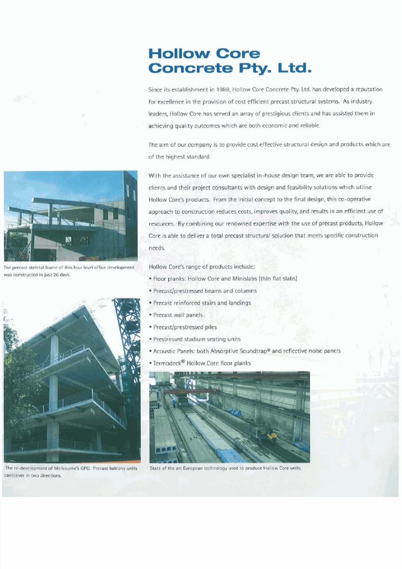
Since its establishment in 1988, Hollow Core Concrete Pty. Ltd. has developed a reputation
for excellence in the provis ion of cost effi cien t precast structural systems. As industry
leaders, Hollow Core has served an array of prestigious cl ients and has assisted them in
achieving quality outcomes which are both economic and reliable.
The aim of our company is to provide cost effective structural design and products which are
of the highest standard.
.
-.:
P
, ;+
i .
With the assistance of our own specialist in-house design team, we are able to provide
clients and their project consultants with design and feasibility solutions which utilise
Hollow Core's products. From the initial concept to the final design, this co-operative
approach t o construction reduces costs, improves quality, and results in an efficient use o f
resources. By combining our renowned expertise with the use o f precast products. Hollow
Core is able to deliver a total precast structural solution that meets specific construction
precast skeletal frame of this four level office development
Hollow Core's range of products include:
constructed in ust 26 days.
Floor planks: Hollow Core and Minislabs (thin flat slabs)
Precastlprestressedbeams and columns
Precast reinforced stairs and landings
Precast wall panels,
Precastlprestressedpiles
Prestressed stadium seating units
S
.
Acoustic Panels: both Absorptive Soundtrap@and reflective noise panels
;
~ e r m o d e c k ~ollow Core floor planks
k
re-development o f Melbourne's GPO. Precast balcony units State o f the art European technology used to produce Hollow Core units.
in two directions.
7/26/2019 Hollow Core Concrete DetailingManual
http://slidepdf.com/reader/full/hollow-core-concrete-detailingmanual 3/41
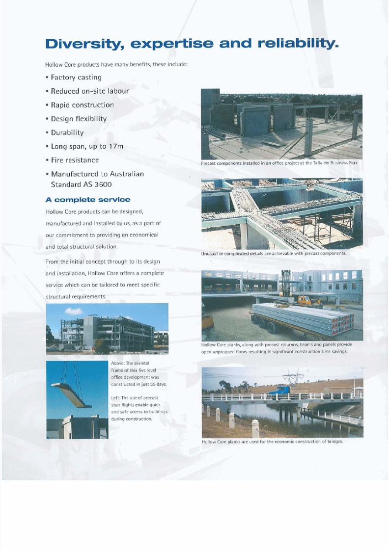
Diversity expertise and reliability.
Hollow Core products have many benefits, these include:
Factory casting
Reduced on-site labour
Rapid construction
Design flexibility
Durability
Long span, up to 17m
U
Fire resistance
Precast components installed in an office project at the Tally Ho Business Park.
Manufactured to Australian
Standard AS 3600
A omplete servi e
Hollow Core products can be designed,
manufactured and installed by us, as a part o f
I
our commitment t o providing an economical
and total structural solution.
.
.\
Unusual or complicated details are achievable with precast components.
From the initial concept throu gh t o i ts design
and installation, Ho llow Core offers a complete
service which can be tailored t o meet specific
structural requirements.
IT
open unpropped floors resulting it7 igfl~fiant o h s t ~ t ~ o pime aVrigs.
- ~ ~ ~ y + ~ ~ y d
g ~cg~- ~vQnent was
kdhstructed in ust 55 days.
eft: The use o f precast
b
tair flights enable quick
~ n dafe access to buildings
luring construction. '
'*',I
&
Hollow Core planks are used for the economic construction of bridges.

7/26/2019 Hollow Core Concrete DetailingManual
http://slidepdf.com/reader/full/hollow-core-concrete-detailingmanual 4/41
n
industry leader
Hollow Core has proven to be a leader in its use of state-of-the-a rt technolog y in
the manufacture o f precast and prestressed concrete products.
We have demonstrated in hundreds of projects versatility qua lity and confidence
In using the most effective safe and efficient m ethod o f construction.
ihis experience in delivering a total structural solut ion has distinct advantages in
the construction o f a wide variety of projects. range o f these include:
.
Office Developments
Sporting Facilities
Apartments and Residences
Schools and Universities
Major Shopping Centres
Churches
Bridges
Factories and Industrial Developments
Top: This multi storey car park development
constructed using Hollow Core planks supported
on a steel frame structure.
Left: The striking Heritage Country Club set in the
Yarra Valley incorporates precast columns beams
panels and Hollow Core floor planks.
Bottom lef t : The full structural frame o f this office
development in Tally Ho Business Park has been
constructed using precast components.
Bottom Right: The success of the Great Southern
Stand saw Hollow Core contracted to supply the
precast components for the Northern Stand
re-development at the Melbourne Cricket Ground.
7/26/2019 Hollow Core Concrete DetailingManual
http://slidepdf.com/reader/full/hollow-core-concrete-detailingmanual 5/41
Hollow Core Concrete
etailing M anu al
Contact Details
P.O. Box 241, Altona North, VIC 3025, Australia
12-14 Maria Street, Laverton North, VIC 3026, Australia
Tel +61 3 9369 4944 Fax +61 3 9369 2025
Email [email protected] Web www.hollowcore.com.au
Published Date: June 2004
Tel: +61 3 9369 4944Fax: + 61 3 9369 2025Email: [email protected] Web: www.hollowcore.com.au
7/26/2019 Hollow Core Concrete DetailingManual
http://slidepdf.com/reader/full/hollow-core-concrete-detailingmanual 6/41
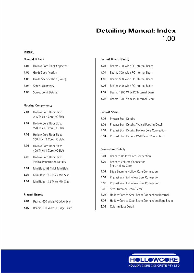
Detailing Manual: Index
1.00
INDEX:
General Details
1.01 Hollow Core Plank Capacity
1.02 Guide Specification
1.03 Guide Specification (Cont.)
1.04 Screed Geometry
1.05 Screed Joint Details
Flooring Components
2.01 Hollow Core Floor Slab:
205 Thick 6 Core HC Slab
2.02 Hollow Core Floor Slab:
220 Thick 5 Core HC Slab
2.03 Hollow Core Floor Slab:
300 Thick 4 Core HC Slab
2.04 Hollow Core Floor Slab:
400 Thick 4 Core HC Slab
2.05 Hollow Core Floor Slab:
Typical Penetration Details
3.01 MiniSlab: 95 Thick MiniSlab
3.02 MiniSlab: 115 Thick MiniSlab
3.03 MiniSlab: 135 Thick MiniSlab
Precast Beams
4.01 Beam: 600 Wide PC Edge Beam
4.02 Beam: 600 Wide PC Edge Beam
Precast Beams Cont.)
4.03 Beam: 700 Wide PC Internal Beam
4.04 Beam: 700 Wide PC Internal Beam
4.05 Beam: 900 Wide PC Internal Beam
4.06 Beam: 900 Wide PC Internal Beam
4.07 Beam: 1200 Wide PC Internal Beam
4.08 Beam: 1200 Wide PC Internal Beam
Precast Stairs
5.01 Precast Stair Details
5.02 Precast Stair Details: Typical Footing Detail
5.03 Precast Stair Details: Hollow Core Connection
5.04 Precast Stair Details: Wall Panel Connection
Connection Details
6.01 Beam to Hollow Core Connection
6.02 Beam to Column Connection(incl. Hollow Core)
6.03 Edge Beam to Hollow Core Connection
6.04 Precast Wall to Hollow Core Connection
6.05 Precast Wall to Hollow Core Connection
6.06 Steel Trimmer Beam Detail
6.07 Hollow Core to Steel Beam Connection: Internal
6.08 Hollow Core to Steel Beam Connection: Edge Beam
6.09 Column Base Detail
Tel: +61 3 9369 4944Fax: + 61 3 9369 2025Email: [email protected]: www.hollowcore.com.au
7/26/2019 Hollow Core Concrete DetailingManual
http://slidepdf.com/reader/full/hollow-core-concrete-detailingmanual 7/41
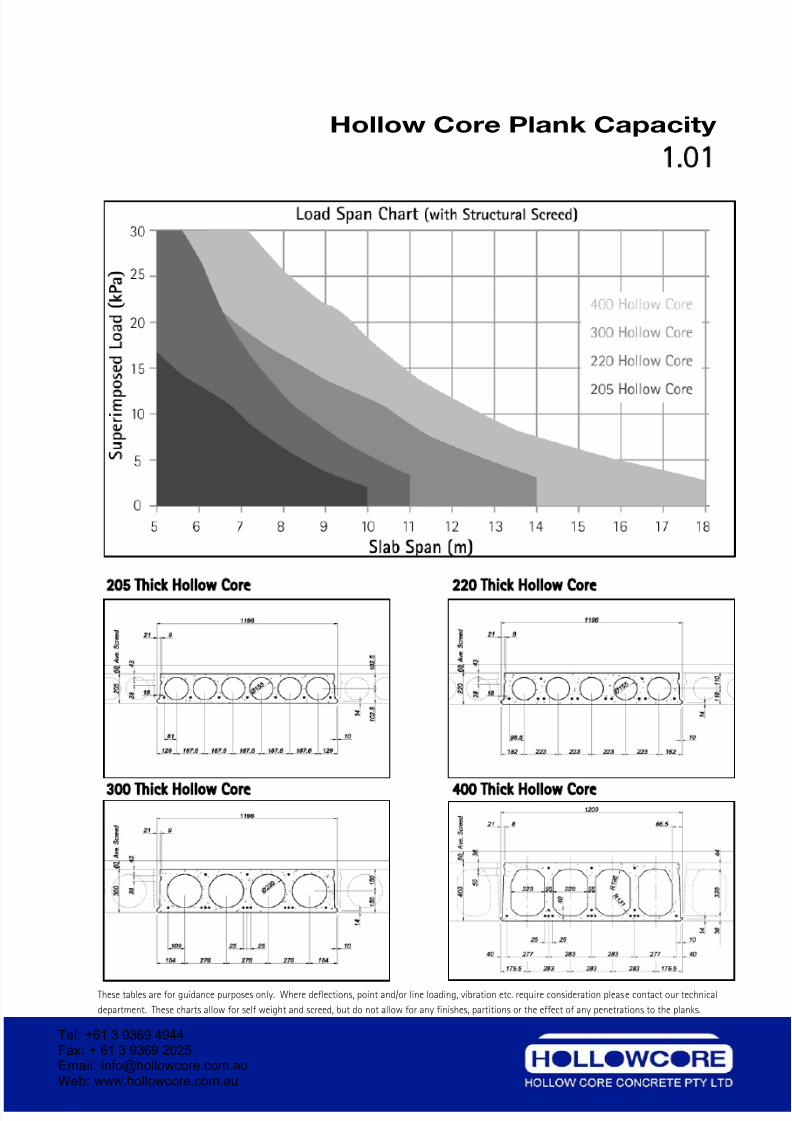
Hollow Core Plank Capacity
1 01
205 Thick Hollow Core 220 Thick Hollow Core
300 Thick Hollow Core 400 Thick Hollow Core
These tables are for guidance purposes only. Where deflections, point and/or line loading, vibration etc. require consideration please contact our technical
department. These charts allow for self weight and screed, but do not allow for any finishes, partitions or the effect of any penetrations to the planks.
Tel: +61 3 9369 4944Fax: + 61 3 9369 2025Email: [email protected] Web: www.hollowcore.com.au
7/26/2019 Hollow Core Concrete DetailingManual
http://slidepdf.com/reader/full/hollow-core-concrete-detailingmanual 8/41
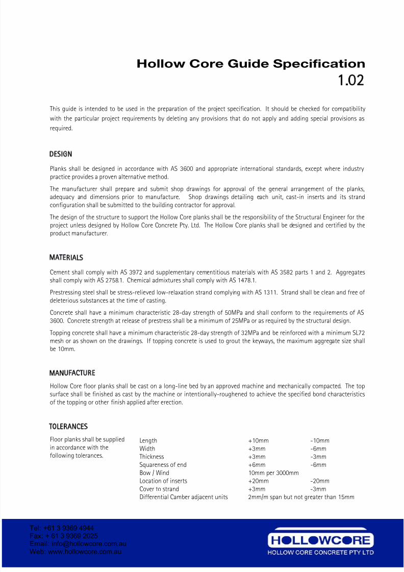
Hollow Core Guide Specification
1.02
This guide is intended to be used in the preparation of the project specification. It should be checked for compatibility
with the particular project requirements by deleting any provisions that do not apply and adding special provisions as
required.
DESIGN
Planks shall be designed in accordance with AS 3600 and appropriate international standards, except where industrypractice provides a proven alternative method.
The manufacturer shall prepare and submit shop drawings for approval of the general arrangement of the planks,
adequacy and dimensions prior to manufacture. Shop drawings detailing each unit, cast-in inserts and its strandconfiguration shall be submitted to the building contractor for approval.
The design of the structure to support the Hollow Core planks shall be the responsibility of the Structural Engineer for theproject unless designed by Hollow Core Concrete Pty. Ltd. The Hollow Core planks shall be designed and certified by theproduct manufacturer.
MATERIALS
Cement shall comply with AS 3972 and supplementary cementitious materials with AS 3582 parts 1 and 2. Aggregatesshall comply with AS 2758.1. Chemical admixtures shall comply with AS 1478.1.
Prestressing steel shall be stress-relieved low-relaxation strand complying with AS 1311. Strand shall be clean and free of
deleterious substances at the time of casting.
Concrete shall have a minimum characteristic 28-day strength of 50MPa and shall conform to the requirements of AS3600. Concrete strength at release of prestress shall be a minimum of 25MPa or as required by the structural design.
Topping concrete shall have a minimum characteristic 28-day strength of 32MPa and be reinforced with a minimum SL72mesh or as shown on the drawings. If topping concrete is used to grout the keyways, the maximum aggregate size shallbe 10mm.
MANUFACTURE
Hollow Core floor planks shall be cast on a long-line bed by an approved machine and mechanically compacted. The topsurface shall be finished as cast by the machine or intentionally-roughened to achieve the specified bond characteristics
of the topping or other finish applied after erection.
TOLERANCES
Floor planks shall be suppliedin accordance with thefollowing tolerances.
Length +10mm -10mmWidth +3mm -6mmThickness +3mm -3mmSquareness of end +6mm -6mmBow / Wind 10mm per 3000mmLocation of inserts +20mm -20mmCover to strand +3mm -3mmDifferential Camber adjacent units 2mm/m span but not greater than 15mm
Tel: +61 3 9369 4944Fax: + 61 3 9369 2025Email: [email protected] Web: www.hollowcore.com.au
7/26/2019 Hollow Core Concrete DetailingManual
http://slidepdf.com/reader/full/hollow-core-concrete-detailingmanual 9/41
Hollow Core Guide Specification
1.03
DELIVERY AND HANDLING
Hollow Core floor planks shall be lifted and supported during manufacture, storage, transport and erection operations atthe lifting positions nominated by the product manufacturer only.
The on site lifting and erection operations shall be in accordance with a site specific ‘Work Method Statement’ producedby the erection contractor in association with product manufacturer. The ‘Work Method Statement’ shall be inaccordance with the appropriate Industry Standard.
ERECTION
The building contractor shall be responsible for providing true and level bearing surfaces for the support of the HollowCore planks. Temporary shoring and bracing shall also be provided as necessary to ensure the stability of the structureduring erection. The Hollow Core planks shall be installed by a competent erection contractor. Where the manufactureralso erects the planks, the building Contractor shall be responsible for providing suitable access at the site to enable trucksand cranes to operate under their own power.
Bearing strips shall be accurately set where required. Any reinforcement required shall be placed as detailed on thedrawings. Keyways shall be filled and compacted with a 3:1 sand-cement grout mix or by the topping concrete using amaximum aggregate size of 10mm. Voids at plank ends shall be sealed to prevent penetration of topping into the cores bymore than 50mm. End filling should not be more than the support length unless detailed by the product manufacturer.
ATTACHMENTS AND PENETRATIONS
Attachments and fixings to the Hollow Core planks shall be in accordance with the approved details only and shall notimpair or reduce the strength of the floor planks.
Penetrations and chases to the Hollow Core planks shall be in accordance with details agreed by the Structural Engineerand the product manufacturer.
IN SITU TOPPING
The Building Contractor shall provide a well-compacted in-situ structural concrete topping to the floor planks as detailedon the drawings. Reinforcement is to be placed in accordance with structural details. The plank surface shall be clean andfree of loose material and surface-moist (saturated surface-dry) immediately prior to placing the topping. Finishing andcuring of the topping should ensure that plastic shrinkage cracks are controlled to acceptable levels. Construction joints
in the topping shall be located as shown on the drawings.
INSPECTION AND ACCEPTANCE
The manufacturer shall provide access to its production facilities for inspection of work in progress by the StructuralEngineer and/or the building contractor to verify conformity of the product to the project specifications.
Tel: +61 3 9369 4944Fax: + 61 3 9369 2025Email: [email protected] Web: www.hollowcore.com.au
7/26/2019 Hollow Core Concrete DetailingManual
http://slidepdf.com/reader/full/hollow-core-concrete-detailingmanual 10/41
Screed Geometry
1 04
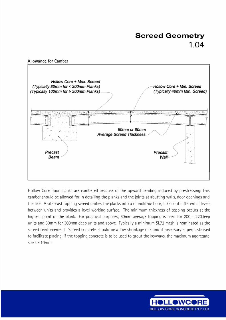
Allowance for Camber
Hollow Core floor planks are cambered because of the upward bending induced by prestressing. This
camber should be allowed for in detailing the planks and the joints at abutting walls, door openings and
the like. A site-cast topping screed unifies the planks into a monolithic floor, takes out differential levels
between units and provides a level working surface. The minimum thickness of topping occurs at the
highest point of the plank. For practical purposes, 60mm average topping is used for 200 - 220deep
units and 80mm for 300mm deep units and above. Typically a minimum SL72 mesh is nominated as thescreed reinforcement. Screed concrete should be a low shrinkage mix and if necessary superplasticised
to facilitate placing, if the topping concrete is to be used to grout the keyways, the maximum aggregate
size be 10mm.
Tel: +61 3 9369 4944Fax: + 61 3 9369 2025Email: [email protected]: www.hollowcore.com.au
7/26/2019 Hollow Core Concrete DetailingManual
http://slidepdf.com/reader/full/hollow-core-concrete-detailingmanual 11/41
Screed Joint Details
1 05
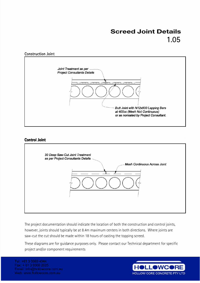
Construction Joint
Control Joint
The project documentation should indicate the location of both the construction and control joints,
however, joints should typically be at 8.4m maximum centers in both directions. Where joints are
saw-cut the cut should be made within 18 hours of casting the topping screed.
These diagrams are for guidance purposes only. Please contact our Technical department for specific
project and/or component requirements
Tel: +61 3 9369 4944Fax: + 61 3 9369 2025Email: [email protected] Web: www.hollowcore.com.au
7/26/2019 Hollow Core Concrete DetailingManual
http://slidepdf.com/reader/full/hollow-core-concrete-detailingmanual 12/41
205 Thick 6 Core HC Slab
2.01
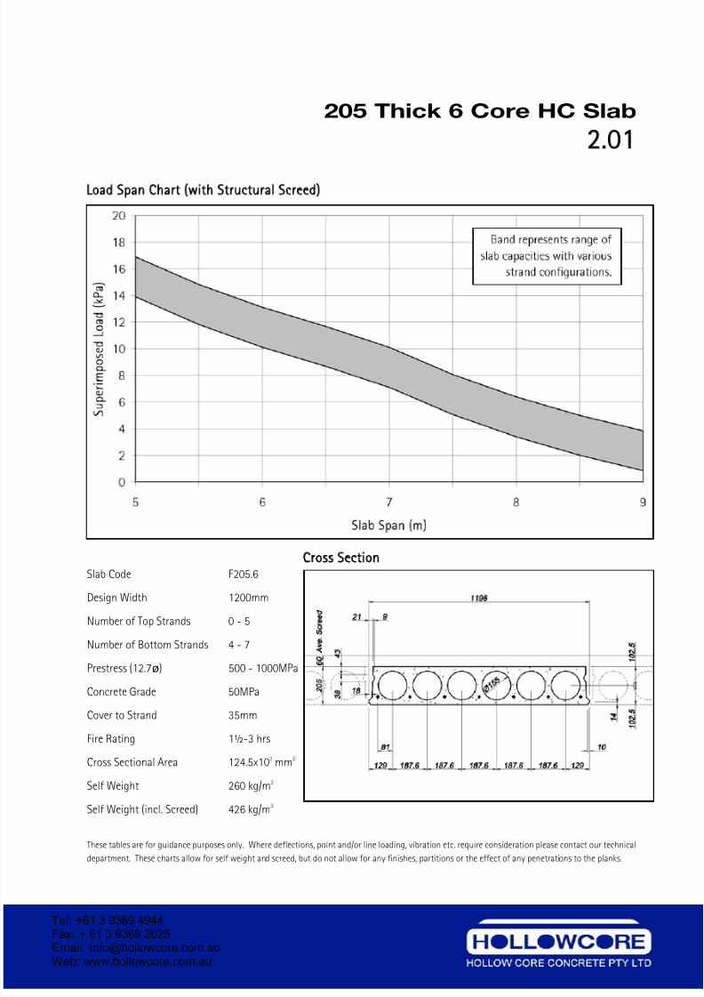
Load Span Chart with Structural Screed)
Cross Section
Slab Code F205.6
Design Width 1200mm
Number of Top Strands 0 - 5
Number of Bottom Strands 4 - 7
Prestress (12.7ø) 500 - 1000MPa
Concrete Grade 50MPa
Cover to Strand 35mm
Fire Rating 1½-3 hrs
Cross Sectional Area 124.5x103 mm2
Self Weight 260 kg/m2
Self Weight (incl. Screed) 426 kg/m2
These tables are for guidance purposes only. Where deflections, point and/or line loading, vibration etc. require consideration please contact our technical
department. These charts allow for self weight and screed, but do not allow for any finishes, partitions or the effect of any penetrations to the planks.
Tel: +61 3 9369 4944Fax: + 61 3 9369 2025Email: [email protected] Web: www.hollowcore.com.au
7/26/2019 Hollow Core Concrete DetailingManual
http://slidepdf.com/reader/full/hollow-core-concrete-detailingmanual 13/41
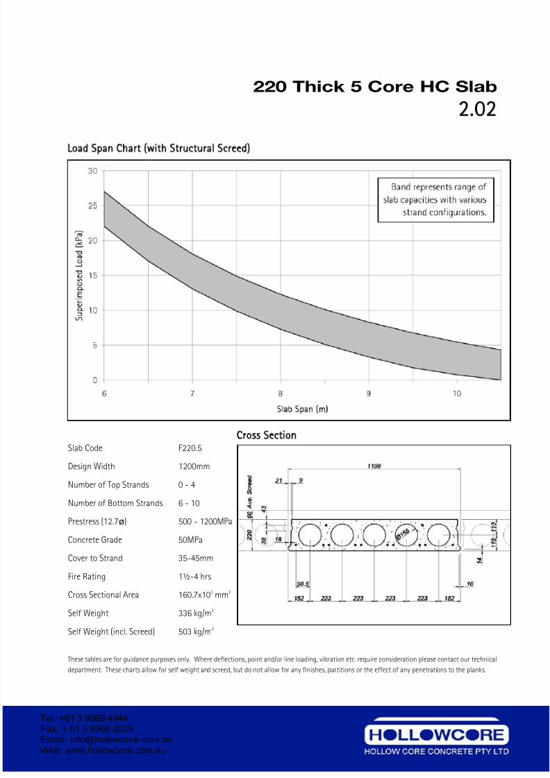
220 Thick 5 Core HC Slab
2.02
Load Span Chart with Structural Screed)
Cross Section
Slab Code F220.5
Design Width 1200mm
Number of Top Strands 0 - 4
Number of Bottom Strands 6 - 10
Prestress (12.7ø) 500 - 1200MPa
Concrete Grade 50MPa
Cover to Strand 35-45mm
Fire Rating 1½-4 hrs
Cross Sectional Area 160.7x103 mm2
Self Weight 336 kg/m2
Self Weight (incl. Screed) 503 kg/m2
These tables are for guidance purposes only. Where deflections, point and/or line loading, vibration etc. require consideration please contact our technical
department. These charts allow for self weight and screed, but do not allow for any finishes, partitions or the effect of any penetrations to the planks.
Tel: +61 3 9369 4944Fax: + 61 3 9369 2025Email: [email protected] Web: www.hollowcore.com.au
7/26/2019 Hollow Core Concrete DetailingManual
http://slidepdf.com/reader/full/hollow-core-concrete-detailingmanual 14/41
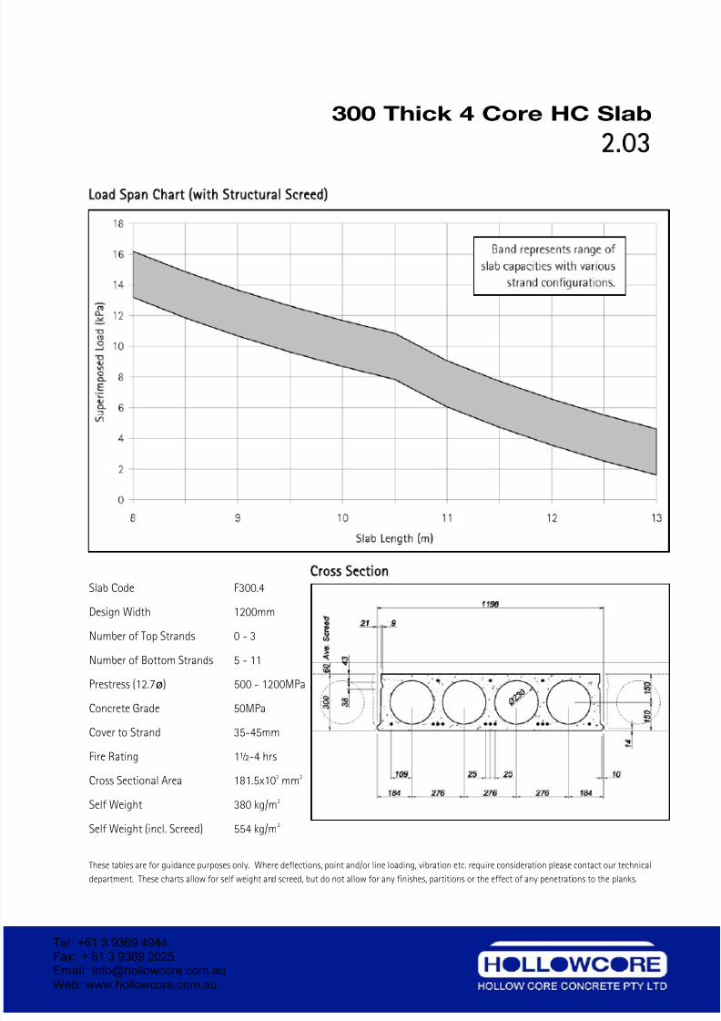
300 Thick 4 Core HC Slab
2.03
Load Span Chart with Structural Screed)
Cross Section
Slab Code F300.4
Design Width 1200mm
Number of Top Strands 0 - 3
Number of Bottom Strands 5 - 11
Prestress (12.7ø) 500 - 1200MPa
Concrete Grade 50MPa
Cover to Strand 35-45mm
Fire Rating 1½-4 hrs
Cross Sectional Area 181.5x103 mm2
Self Weight 380 kg/m2
Self Weight (incl. Screed) 554 kg/m2
These tables are for guidance purposes only. Where deflections, point and/or line loading, vibration etc. require consideration please contact our technical
department. These charts allow for self weight and screed, but do not allow for any finishes, partitions or the effect of any penetrations to the planks.
Tel: +61 3 9369 4944Fax: + 61 3 9369 2025Email: [email protected] Web: www.hollowcore.com.au
7/26/2019 Hollow Core Concrete DetailingManual
http://slidepdf.com/reader/full/hollow-core-concrete-detailingmanual 15/41
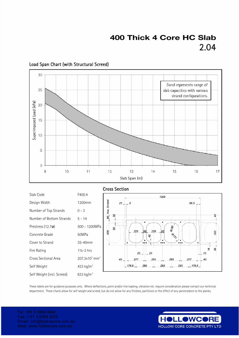
400 Thick 4 Core HC Slab
2.04
Load Span Chart with Structural Screed)
Cross Section
Slab Code F400.4
Design Width 1200mm
Number of Top Strands 0 - 3
Number of Bottom Strands 5 - 14
Prestress (12.7ø) 500 - 1200MPa
Concrete Grade 50MPa
Cover to Strand 35-40mm
Fire Rating 1½-3 hrs
Cross Sectional Area 207.3x103 mm2
Self Weight 433 kg/m2
Self Weight (incl. Screed) 633 kg/m2
These tables are for guidance purposes only. Where deflections, point and/or line loading, vibration etc. require consideration please contact our technical
department. These charts allow for self weight and screed, but do not allow for any finishes, partitions or the effect of any penetrations to the planks.
Tel: +61 3 9369 4944Fax: + 61 3 9369 2025Email: [email protected] Web: www.hollowcore.com.au
7/26/2019 Hollow Core Concrete DetailingManual
http://slidepdf.com/reader/full/hollow-core-concrete-detailingmanual 16/41
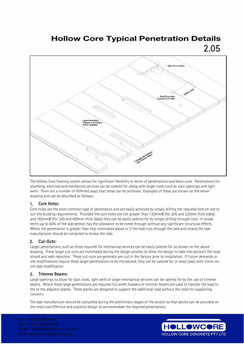
Hollow Core Typical Penetration Details
2.05
Load Span Chart with Structural Screed)
The Hollow Core flooring system allows for significant flexibility in terms of penetrations and block-outs. Penetrations forplumbing, electrical and mechanical services can be catered for along with larger voids such as stair openings and lightwells. There are a number of different ways that these can be achieved. Examples of these are shown on the abovedrawing and can be described as follows:
1. Core Holes:
Core holes are the most common type of penetration and are easily achieved by simply drilling the required hole on site tosuit the building requirements. Provided the core holes are not greater than 120mmØ (for 205 and 220mm thick slabs)and 165mmØ (for 300 and 400mm thick slabs) they can be easily catered for by simply drilling through core. In broadterms up to 65% of the slab section has the allowance to be cored through without any significant structural effects.Where the penetration is greater than that nominated above or if the hole cuts through the web and strand the slabmanufacturer should be contacted to review the slab.
2. Cut-Outs:
Larger penetrations, such as those required for mechanical services can be easily catered for as shown on the abovedrawing. These larger cut-outs are nominated during the design process to allow the design to take into account the localstrand and web reduction. These cut-outs are generally pre-cut in the factory prior to installation. If future demands orsite modifications require these larger penetrations to be introduced, they can be catered for in most cases with minor on-site slab modification.
3. Trimmer Beams:
Large openings to allow for stair voids, light wells or larger mechanical services can be catered for by the use of trimmerbeams. Where these large penetrations are required full width headers or trimmer beams are used to transfer the load tothe to the adjacent planks. These planks are designed to support the additional load without the need for supportingcolumns.
The slab manufacturer should be consulted during the preliminary stages of the project so that advice can be provided onthe most cost effective and practical design to accommodate the required penetrations.
Tel: +61 3 9369 4944Fax: + 61 3 9369 2025Email: [email protected] Web: www.hollowcore.com.au
7/26/2019 Hollow Core Concrete DetailingManual
http://slidepdf.com/reader/full/hollow-core-concrete-detailingmanual 17/41
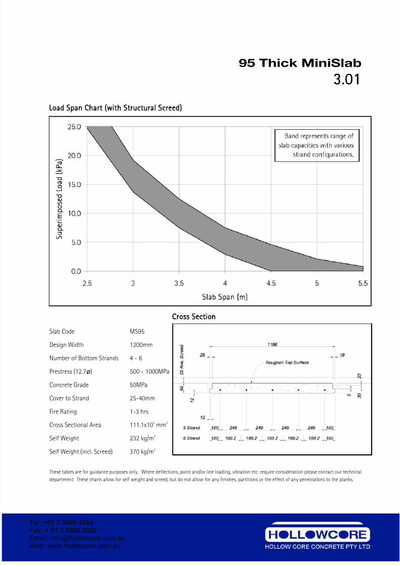
95 Thick MiniSlab
3.01
Load Span Chart with Structural Screed)
Cross Section
Slab Code MS95
Design Width 1200mm
Number of Bottom Strands 4 - 6
Prestress (12.7ø) 500 - 1000MPa
Concrete Grade 50MPa
Cover to Strand 25-40mm
Fire Rating 1-3 hrs
Cross Sectional Area 111.1x103 mm2
Self Weight 232 kg/m2
Self Weight (incl. Screed) 370 kg/m2
These tables are for guidance purposes only. Where deflections, point and/or line loading, vibration etc. require consideration please contact our technical
department. These charts allow for self weight and screed, but do not allow for any finishes, partitions or the effect of any penetrations to the planks.
Tel: +61 3 9369 4944Fax: + 61 3 9369 2025Email: [email protected] Web: www.hollowcore.com.au
7/26/2019 Hollow Core Concrete DetailingManual
http://slidepdf.com/reader/full/hollow-core-concrete-detailingmanual 18/41
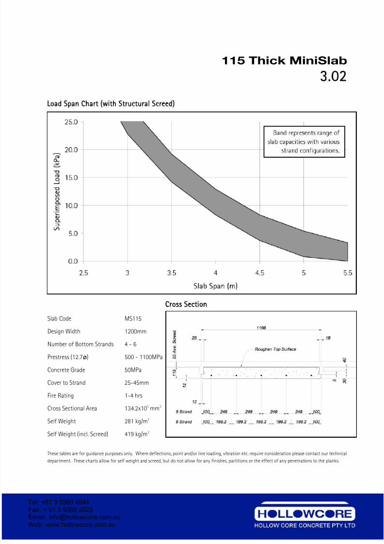
115 Thick MiniSlab
3.02
Load Span Chart with Structural Screed)
Cross Section
Slab Code MS115
Design Width 1200mm
Number of Bottom Strands 4 - 6
Prestress (12.7ø) 500 - 1100MPa
Concrete Grade 50MPa
Cover to Strand 25-45mm
Fire Rating 1-4 hrs
Cross Sectional Area 134.2x103 mm2
Self Weight 281 kg/m2
Self Weight (incl. Screed) 419 kg/m2
These tables are for guidance purposes only. Where deflections, point and/or line loading, vibration etc. require consideration please contact our technical
department. These charts allow for self weight and screed, but do not allow for any finishes, partitions or the effect of any penetrations to the planks.
Tel: +61 3 9369 4944Fax: + 61 3 9369 2025Email: [email protected] Web: www.hollowcore.com.au
7/26/2019 Hollow Core Concrete DetailingManual
http://slidepdf.com/reader/full/hollow-core-concrete-detailingmanual 19/41
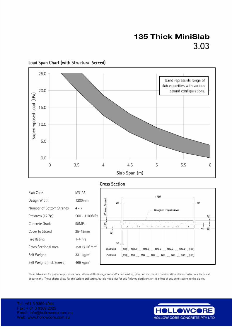
135 Thick MiniSlab
3.03
Load Span Chart with Structural Screed)
Cross Section
Slab Code MS135
Design Width 1200mm
Number of Bottom Strands 4 - 7
Prestress (12.7ø) 500 - 1100MPa
Concrete Grade 50MPa
Cover to Strand 25-45mm
Fire Rating 1-4 hrs
Cross Sectional Area 158.1x103 mm2
Self Weight 331 kg/m2
Self Weight (incl. Screed) 469 kg/m2
These tables are for guidance purposes only. Where deflections, point and/or line loading, vibration etc. require consideration please contact our technical
department. These charts allow for self weight and screed, but do not allow for any finishes, partitions or the effect of any penetrations to the planks.
Tel: +61 3 9369 4944Fax: + 61 3 9369 2025Email: [email protected] Web: www.hollowcore.com.au
7/26/2019 Hollow Core Concrete DetailingManual
http://slidepdf.com/reader/full/hollow-core-concrete-detailingmanual 20/41
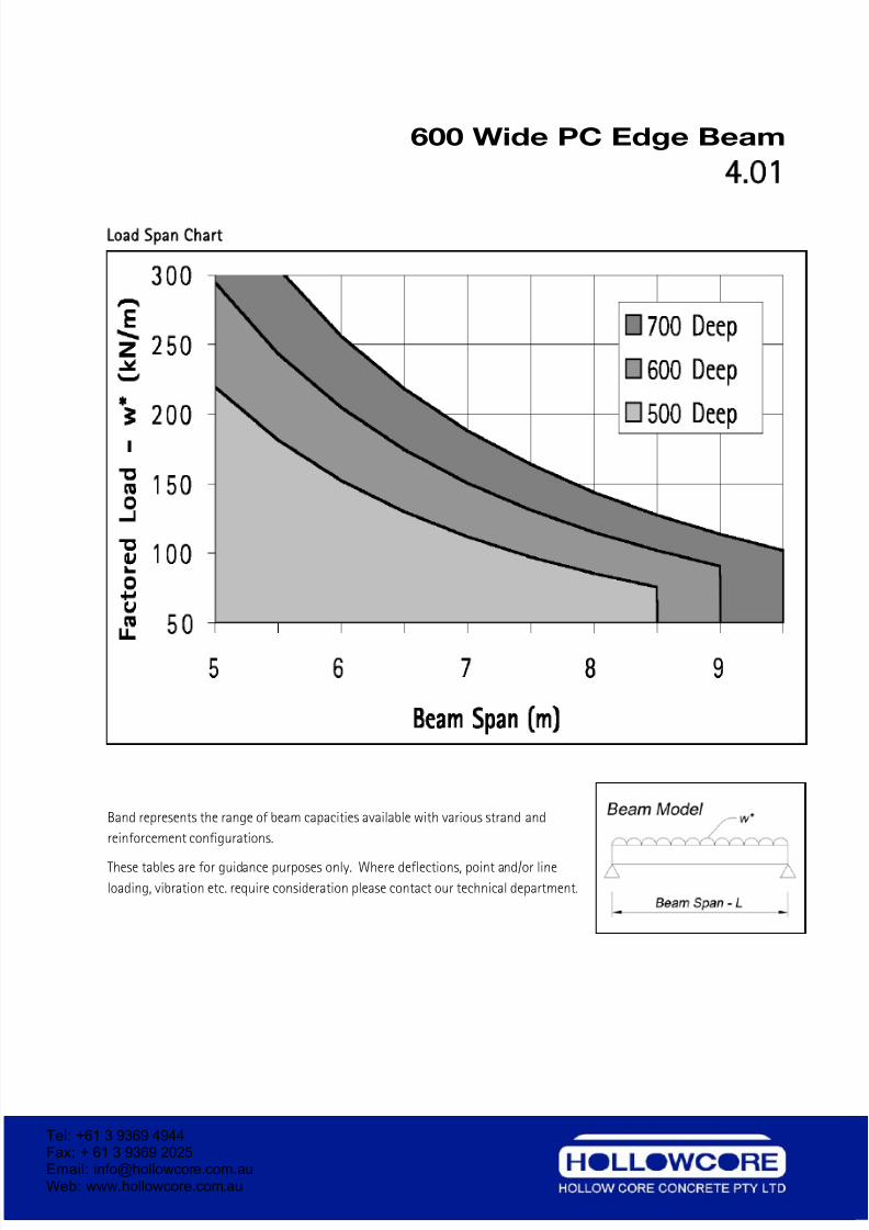
600 Wide PC Edge Beam
4 01
Load Span Chart
Band represents the range of beam capacities available with various strand and
reinforcement configurations.
These tables are for guidance purposes only. Where deflections, point and/or line
loading, vibration etc. require consideration please contact our technical department.
Tel: +61 3 9369 4944Fax: + 61 3 9369 2025Email: [email protected] Web: www.hollowcore.com.au
Tel: +61 3 9369 4944Fax: + 61 3 9369 2025Email: [email protected] Web: www.hollowcore.com.au
7/26/2019 Hollow Core Concrete DetailingManual
http://slidepdf.com/reader/full/hollow-core-concrete-detailingmanual 21/41
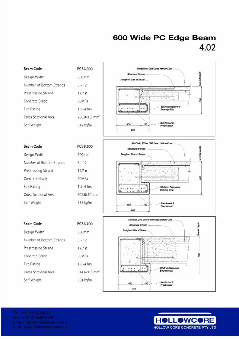
600 Wide PC Edge Beam
4 02
Beam Code PCB6 500
Design Width 600mm
Number of Bottom Strands 6 - 12
Prestressing Strand 12.7 ø
Concrete Grade 50MPa
Fire Rating 1½-4 hrs
Cross Sectional Area 256.8x10
3
mm
2
Self Weight 642 kg/m
Beam Code PCB6 600
Design Width 600mm
Number of Bottom Strands 6 - 12
Prestressing Strand 12.7 ø
Concrete Grade 50MPa
Fire Rating 1½-4 hrs
Cross Sectional Area 302.6x103 mm2
Self Weight 756 kg/m
Beam Code PCB6 700
Design Width 600mm
Number of Bottom Strands 6 - 12
Prestressing Strand 12.7 ø
Concrete Grade 50MPa
Fire Rating 1½-4 hrs
Cross Sectional Area 344.6x103 mm2
Self Weight 861 kg/m
Tel: +61 3 9369 4944Fax: + 61 3 9369 2025Email: [email protected] Web: www.hollowcore.com.au
Tel: +61 3 9369 4944Fax: + 61 3 9369 2025Email: [email protected] Web: www.hollowcore.com.au
7/26/2019 Hollow Core Concrete DetailingManual
http://slidepdf.com/reader/full/hollow-core-concrete-detailingmanual 22/41
700 Wide PC Internal Beam
4 03
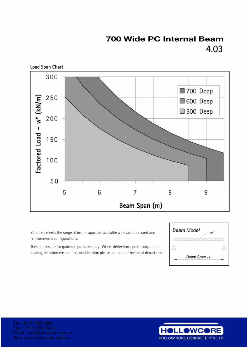
Load Span Chart
Band represents the range of beam capacities available with various strand and
reinforcement configurations.
These tables are for guidance purposes only. Where deflections, point and/or line
loading, vibration etc. require consideration please contact our technical department.
Tel: +61 3 9369 4944Fax: + 61 3 9369 2025Email: [email protected] Web: www.hollowcore.com.au
Tel: +61 3 9369 4944Fax: + 61 3 9369 2025Email: [email protected] Web: www.hollowcore.com.au
7/26/2019 Hollow Core Concrete DetailingManual
http://slidepdf.com/reader/full/hollow-core-concrete-detailingmanual 23/41
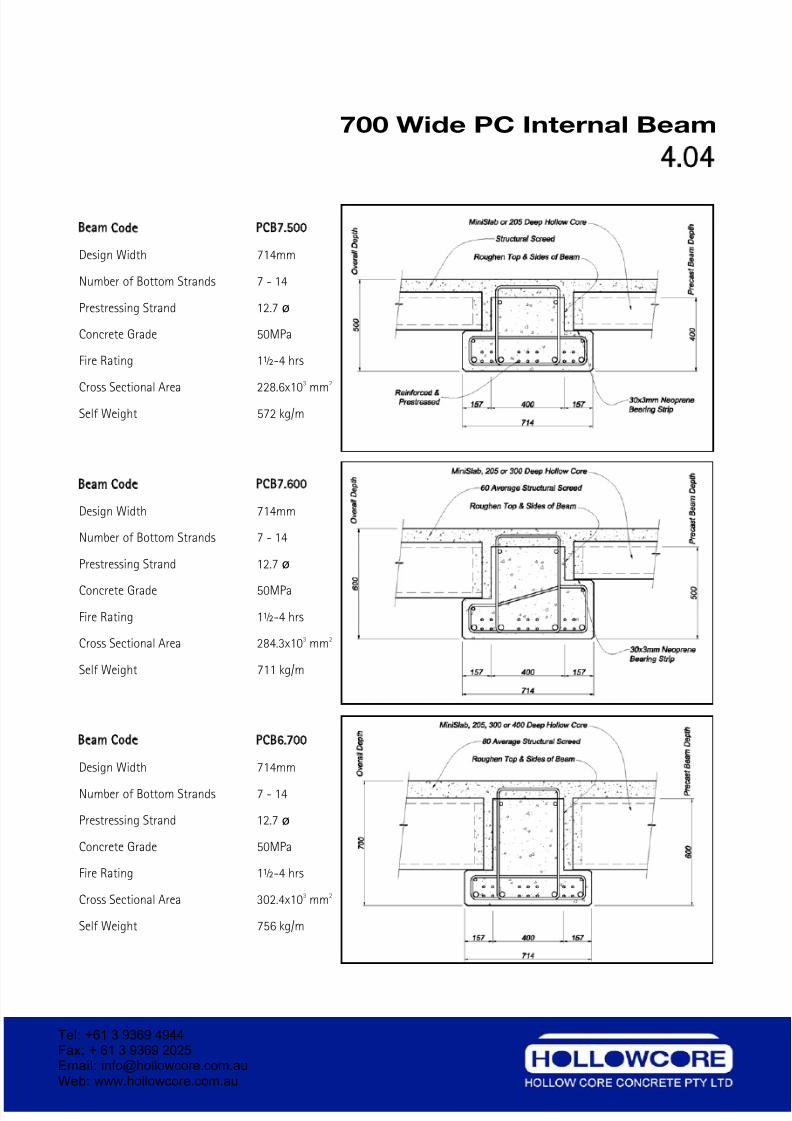
700 Wide PC Internal Beam
4 04
Beam Code PCB7 500
Design Width 714mm
Number of Bottom Strands 7 - 14
Prestressing Strand 12.7 ø
Concrete Grade 50MPa
Fire Rating 1½-4 hrs
Cross Sectional Area 228.6x10
3
mm
2
Self Weight 572 kg/m
Beam Code PCB7 600
Design Width 714mm
Number of Bottom Strands 7 - 14
Prestressing Strand 12.7 ø
Concrete Grade 50MPa
Fire Rating 1½-4 hrs
Cross Sectional Area 284.3x103 mm2
Self Weight 711 kg/m
Beam Code PCB6 700
Design Width 714mm
Number of Bottom Strands 7 - 14
Prestressing Strand 12.7 ø
Concrete Grade 50MPa
Fire Rating 1½-4 hrs
Cross Sectional Area 302.4x103 mm2
Self Weight 756 kg/m
Tel: +61 3 9369 4944Fax: + 61 3 9369 2025Email: [email protected] Web: www.hollowcore.com.au
7/26/2019 Hollow Core Concrete DetailingManual
http://slidepdf.com/reader/full/hollow-core-concrete-detailingmanual 24/41
900 Wide PC Internal Beam
4 05
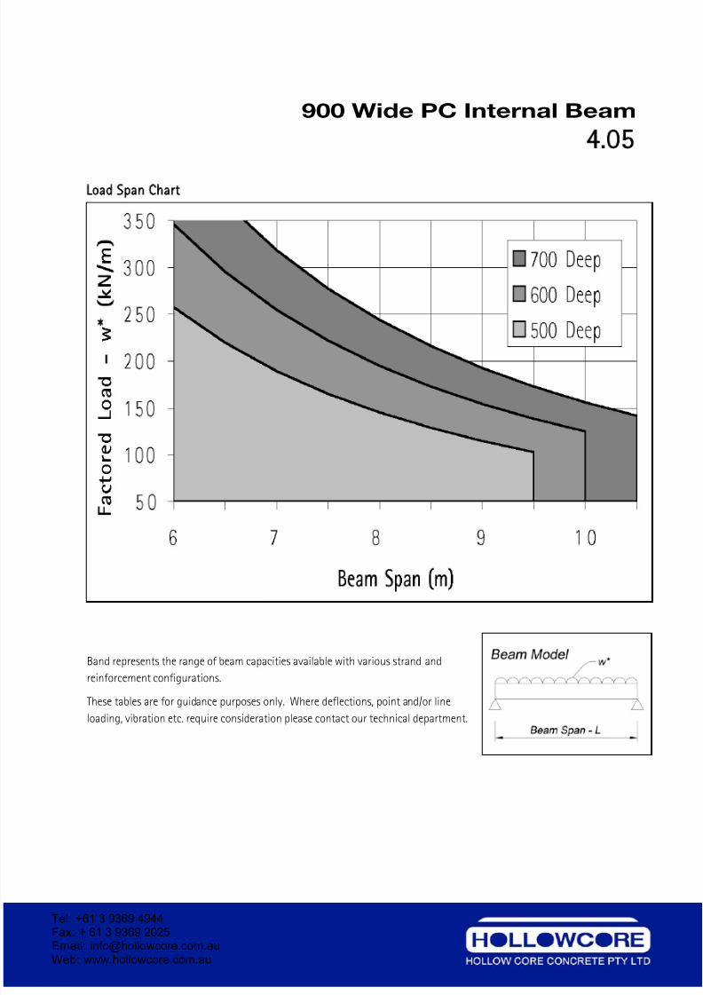
Load Span Chart
Band represents the range of beam capacities available with various strand and
reinforcement configurations.
These tables are for guidance purposes only. Where deflections, point and/or line
loading, vibration etc. require consideration please contact our technical department.
Tel: +61 3 9369 4944Fax: + 61 3 9369 2025Email: [email protected] Web: www.hollowcore.com.au
7/26/2019 Hollow Core Concrete DetailingManual
http://slidepdf.com/reader/full/hollow-core-concrete-detailingmanual 25/41
900 Wide PC Internal Beam
4 06
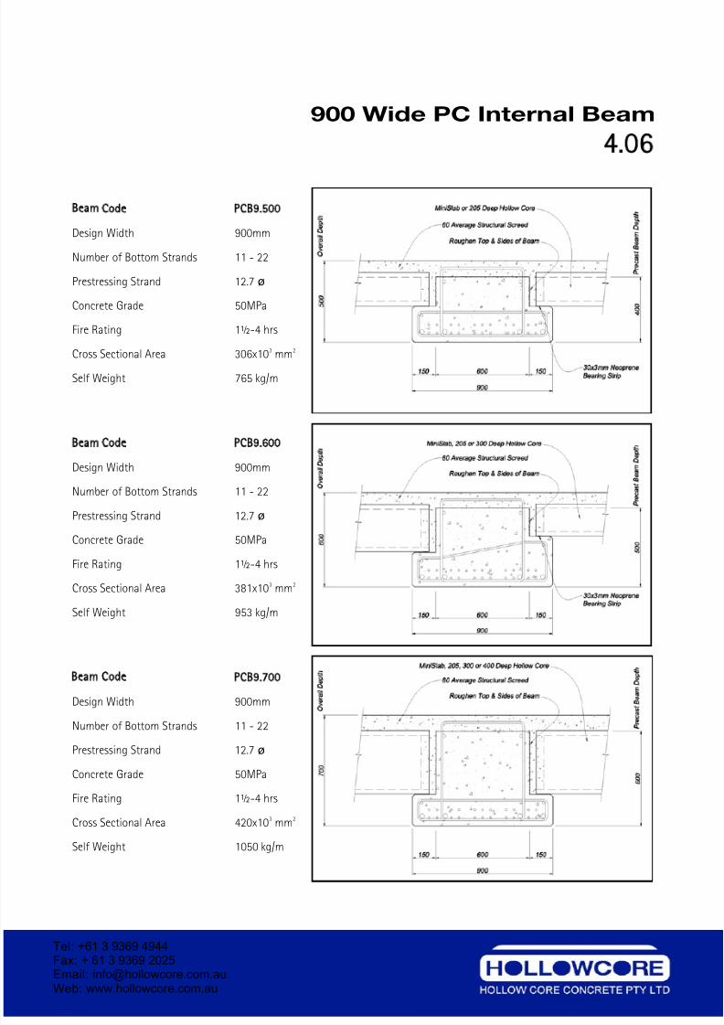
Beam Code PCB9 500
Design Width 900mm
Number of Bottom Strands 11 - 22
Prestressing Strand 12.7 ø
Concrete Grade 50MPa
Fire Rating 1½-4 hrs
Cross Sectional Area 306x10
3
mm
2
Self Weight 765 kg/m
Beam Code PCB9 600
Design Width 900mm
Number of Bottom Strands 11 - 22
Prestressing Strand 12.7 ø
Concrete Grade 50MPa
Fire Rating 1½-4 hrs
Cross Sectional Area 381x103 mm2
Self Weight 953 kg/m
Beam Code PCB9 700
Design Width 900mm
Number of Bottom Strands 11 - 22
Prestressing Strand 12.7 ø
Concrete Grade 50MPa
Fire Rating 1½-4 hrs
Cross Sectional Area 420x103 mm2
Self Weight 1050 kg/m
Tel: +61 3 9369 4944Fax: + 61 3 9369 2025Email: [email protected] Web: www.hollowcore.com.au
7/26/2019 Hollow Core Concrete DetailingManual
http://slidepdf.com/reader/full/hollow-core-concrete-detailingmanual 26/41
1200 Wide PC Internal Beam
4 07
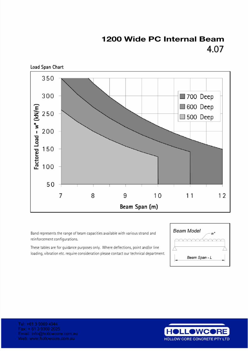
Load Span Chart
Band represents the range of beam capacities available with various strand and
reinforcement configurations.
These tables are for guidance purposes only. Where deflections, point and/or line
loading, vibration etc. require consideration please contact our technical department.
Tel: +61 3 9369 4944Fax: + 61 3 9369 2025Email: [email protected] Web: www.hollowcore.com.au
7/26/2019 Hollow Core Concrete DetailingManual
http://slidepdf.com/reader/full/hollow-core-concrete-detailingmanual 27/41
1200 Wide PC Internal Beam
4 08
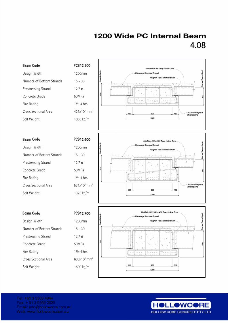
Beam Code PCB12 500
Design Width 1200mm
Number of Bottom Strands 15 - 30
Prestressing Strand 12.7 ø
Concrete Grade 50MPa
Fire Rating 1½-4 hrs
Cross Sectional Area 426x10
3
mm
2
Self Weight 1065 kg/m
Beam Code PCB12 600
Design Width 1200mm
Number of Bottom Strands 15 - 30
Prestressing Strand 12.7 ø
Concrete Grade 50MPa
Fire Rating 1½-4 hrs
Cross Sectional Area 531x103 mm2
Self Weight 1328 kg/m
Beam Code PCB12 700
Design Width 1200mm
Number of Bottom Strands 15 - 30
Prestressing Strand 12.7 ø
Concrete Grade 50MPa
Fire Rating 1½-4 hrs
Cross Sectional Area 600x103 mm2
Self Weight 1500 kg/m
Tel: +61 3 9369 4944Fax: + 61 3 9369 2025Email: [email protected] Web: www.hollowcore.com.au
7/26/2019 Hollow Core Concrete DetailingManual
http://slidepdf.com/reader/full/hollow-core-concrete-detailingmanual 28/41
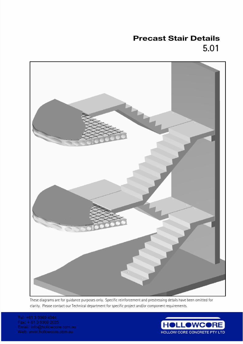
Precast Stair Details
5 01
Connection Detail
These diagrams are for guidance purposes only. Specific reinforcement and prestressing details have been omitted forclarity. Please contact our Technical department for specific project and/or component requirements.
Tel: +61 3 9369 4944Fax: + 61 3 9369 2025Email: [email protected] Web: www.hollowcore.com.au
7/26/2019 Hollow Core Concrete DetailingManual
http://slidepdf.com/reader/full/hollow-core-concrete-detailingmanual 29/41
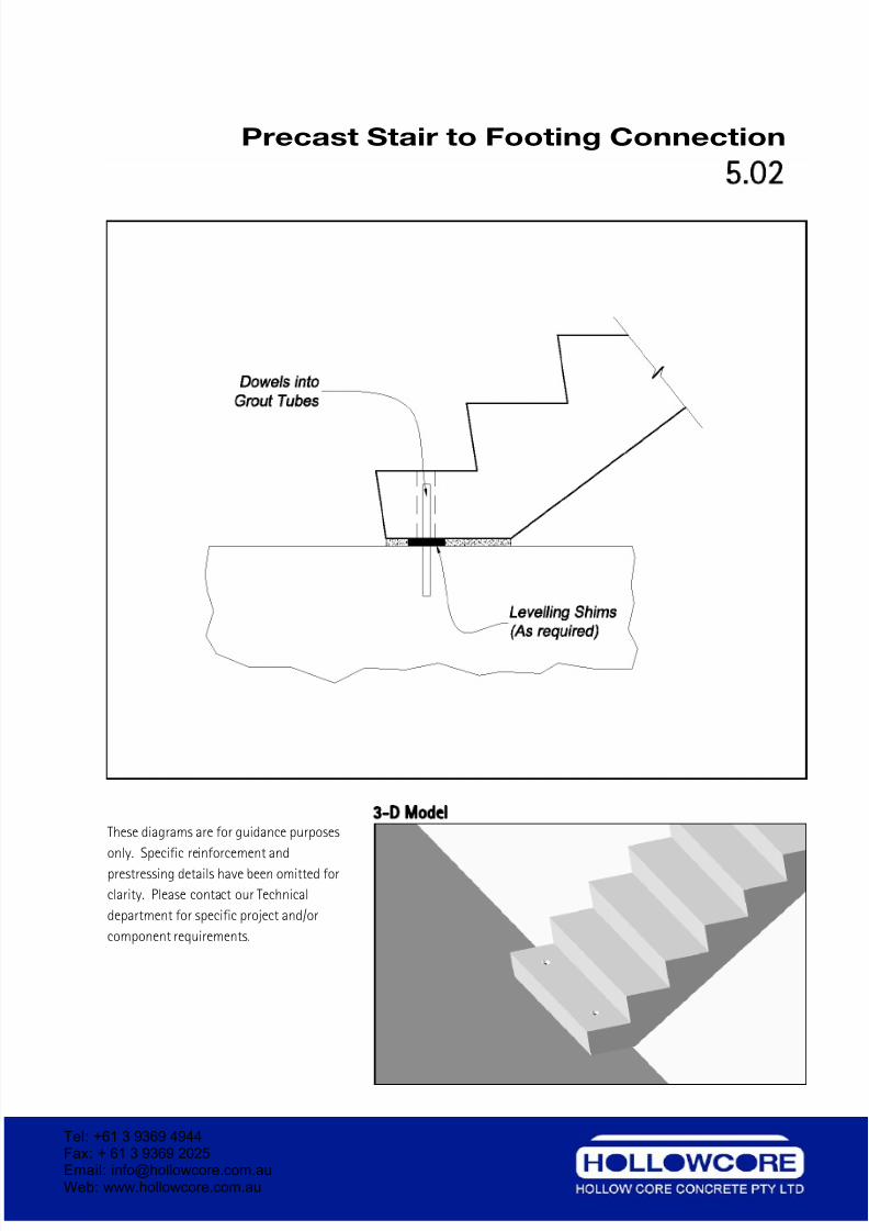
Precast Stair to Footing Connection
5.02
3 D Model
These diagrams are for guidance purposes
only. Specific reinforcement and
prestressing details have been omitted for
clarity. Please contact our Technical
department for specific project and/or
component requirements.
Tel: +61 3 9369 4944Fax: + 61 3 9369 2025Email: [email protected] Web: www.hollowcore.com.au
7/26/2019 Hollow Core Concrete DetailingManual
http://slidepdf.com/reader/full/hollow-core-concrete-detailingmanual 30/41
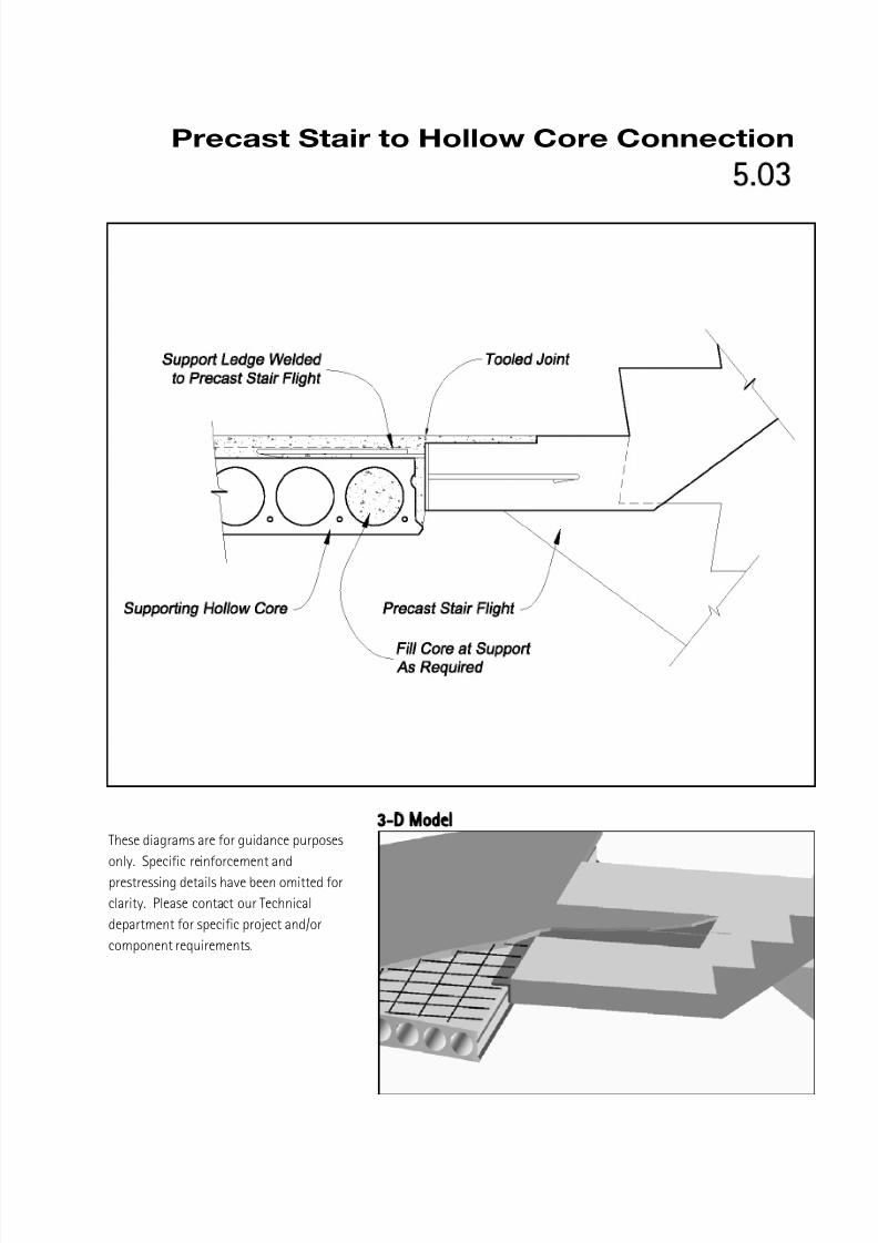
Precast Stair to Hollow Core Connection
5.03
3 D Model
These diagrams are for guidance purposes
only. Specific reinforcement and
prestressing details have been omitted for
clarity. Please contact our Technical
department for specific project and/or
component requirements.
7/26/2019 Hollow Core Concrete DetailingManual
http://slidepdf.com/reader/full/hollow-core-concrete-detailingmanual 31/41
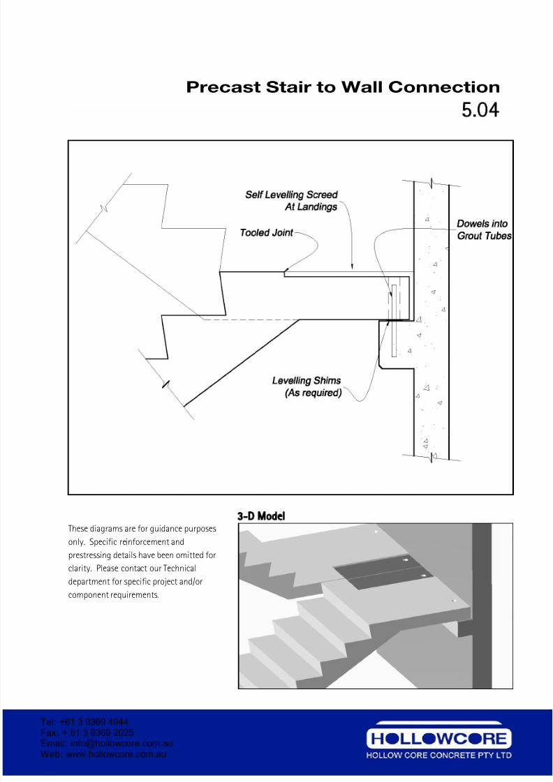
Precast Stair to Wall Connection
5.04
3 D Model
These diagrams are for guidance purposes
only. Specific reinforcement and
prestressing details have been omitted for
clarity. Please contact our Technical
department for specific project and/or
component requirements.
Tel: +61 3 9369 4944Fax: + 61 3 9369 2025Email: [email protected] Web: www.hollowcore.com.au
7/26/2019 Hollow Core Concrete DetailingManual
http://slidepdf.com/reader/full/hollow-core-concrete-detailingmanual 32/41
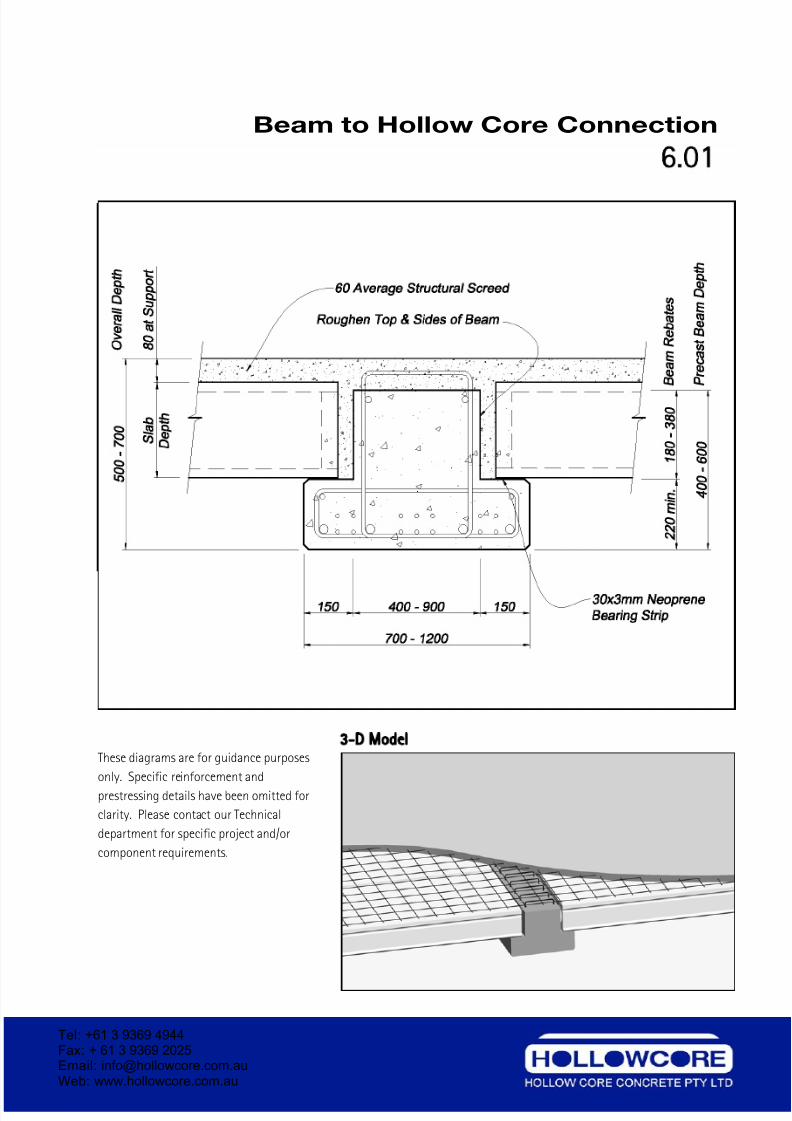
Beam to Hollow Core Connection
6.01
3 D Model
These diagrams are for guidance purposes
only. Specific reinforcement and
prestressing details have been omitted for
clarity. Please contact our Technical
department for specific project and/or
component requirements.
Tel: +61 3 9369 4944Fax: + 61 3 9369 2025Email: [email protected] Web: www.hollowcore.com.au
7/26/2019 Hollow Core Concrete DetailingManual
http://slidepdf.com/reader/full/hollow-core-concrete-detailingmanual 33/41
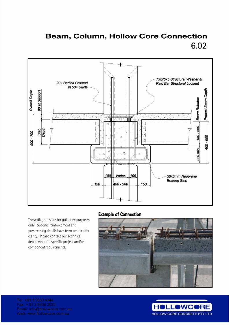
Beam, Column, Hollow Core Connection
6 02
Example of Connection
These diagrams are for guidance purposes
only. Specific reinforcement and
prestressing details have been omitted for
clarity. Please contact our Technical
department for specific project and/or
component requirements.
Tel: +61 3 9369 4944Fax: + 61 3 9369 2025Email: [email protected] Web: www.hollowcore.com.au
7/26/2019 Hollow Core Concrete DetailingManual
http://slidepdf.com/reader/full/hollow-core-concrete-detailingmanual 34/41
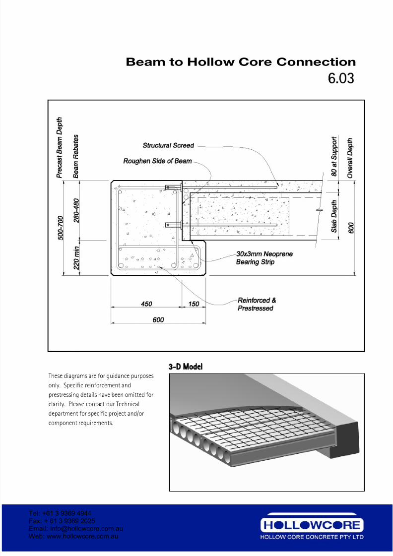
Beam to Hollow Core Connection
6.03
3 D Model
These diagrams are for guidance purposes
only. Specific reinforcement and
prestressing details have been omitted for
clarity. Please contact our Technical
department for specific project and/or
component requirements.
Tel: +61 3 9369 4944Fax: + 61 3 9369 2025Email: [email protected] Web: www.hollowcore.com.au
7/26/2019 Hollow Core Concrete DetailingManual
http://slidepdf.com/reader/full/hollow-core-concrete-detailingmanual 35/41
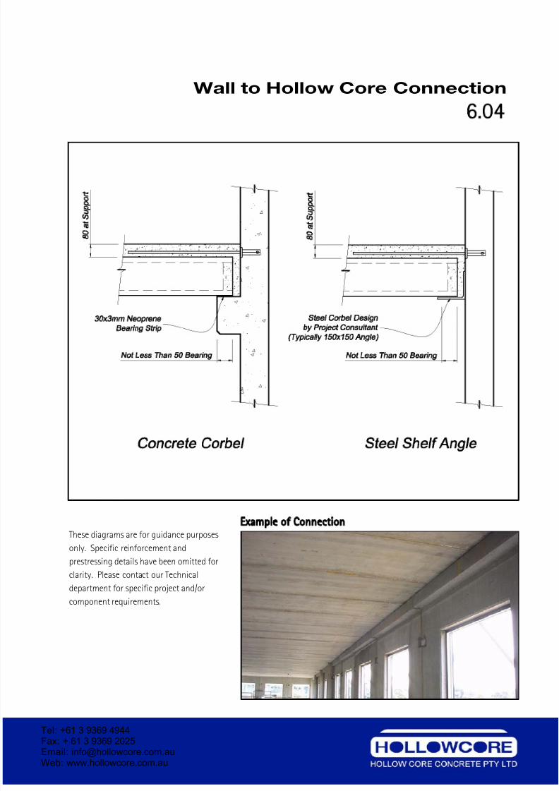
Wall to Hollow Core Connection
6 04
Example of Connection
These diagrams are for guidance purposes
only. Specific reinforcement and
prestressing details have been omitted for
clarity. Please contact our Technical
department for specific project and/or
component requirements.
Tel: +61 3 9369 4944Fax: + 61 3 9369 2025Email: [email protected] Web: www.hollowcore.com.au
7/26/2019 Hollow Core Concrete DetailingManual
http://slidepdf.com/reader/full/hollow-core-concrete-detailingmanual 36/41
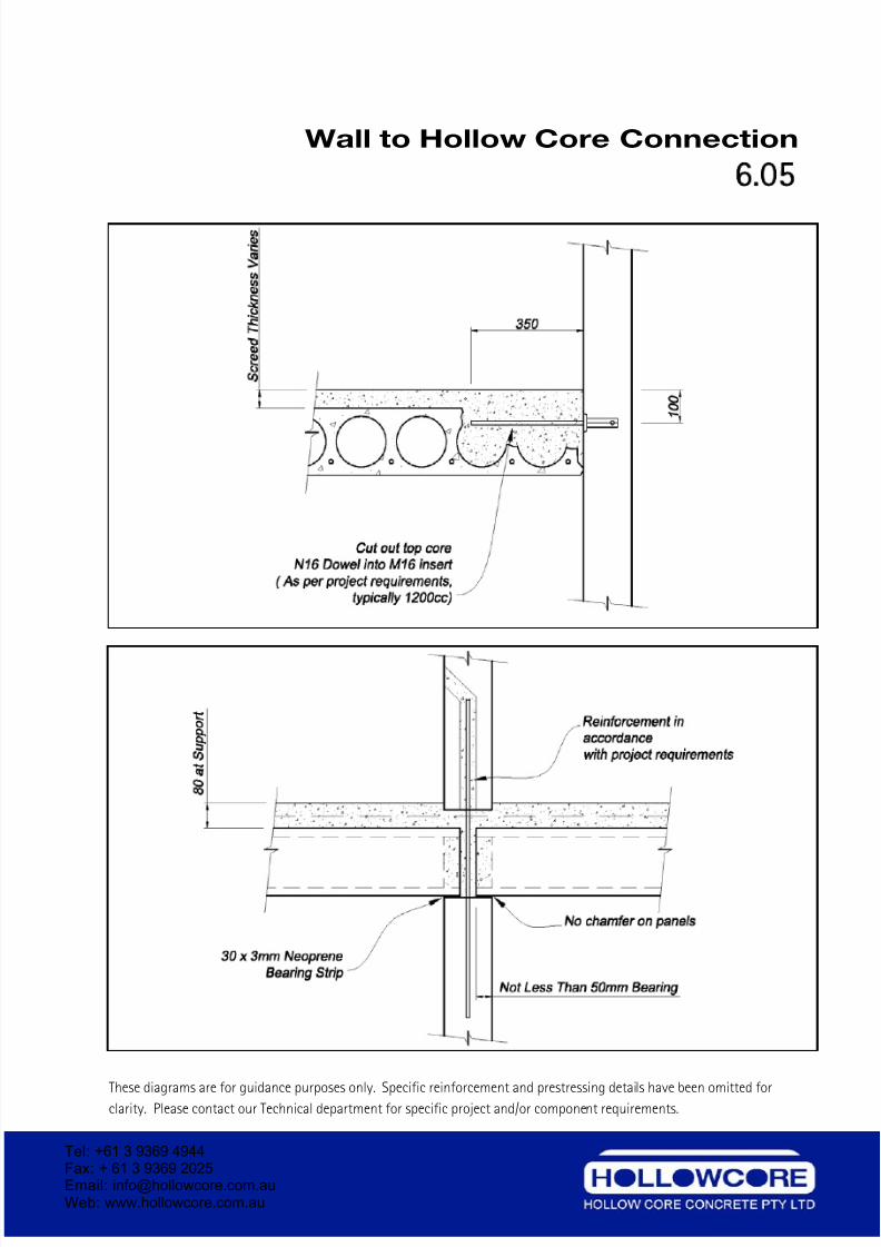
Wall to Hollow Core Connection
6 05
Connection Detail
These diagrams are for guidance purposes only. Specific reinforcement and prestressing details have been omitted forclarity. Please contact our Technical department for specific project and/or component requirements.
Tel: +61 3 9369 4944Fax: + 61 3 9369 2025Email: [email protected] Web: www.hollowcore.com.au
7/26/2019 Hollow Core Concrete DetailingManual
http://slidepdf.com/reader/full/hollow-core-concrete-detailingmanual 37/41
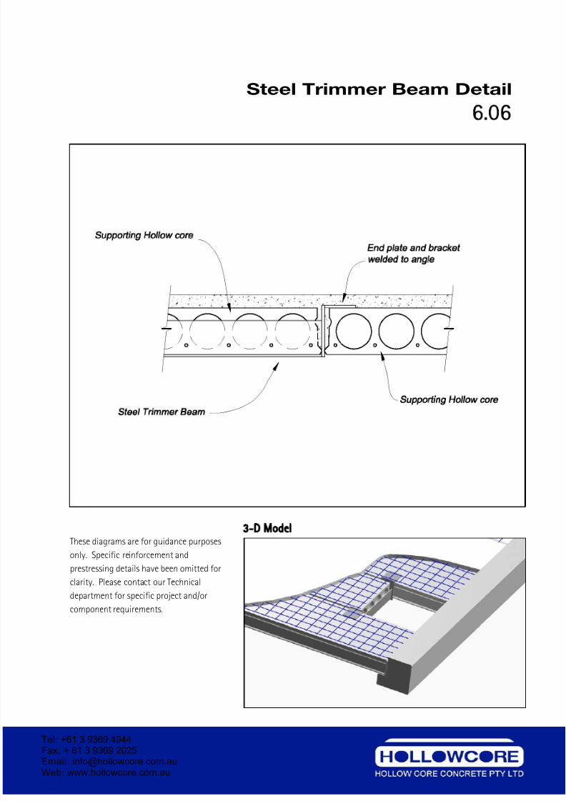
Steel Trimmer Beam Detail
6.06
3 D Model
These diagrams are for guidance purposes
only. Specific reinforcement and
prestressing details have been omitted for
clarity. Please contact our Technical
department for specific project and/or
component requirements.
Tel: +61 3 9369 4944Fax: + 61 3 9369 2025Email: [email protected] Web: www.hollowcore.com.au
7/26/2019 Hollow Core Concrete DetailingManual
http://slidepdf.com/reader/full/hollow-core-concrete-detailingmanual 38/41
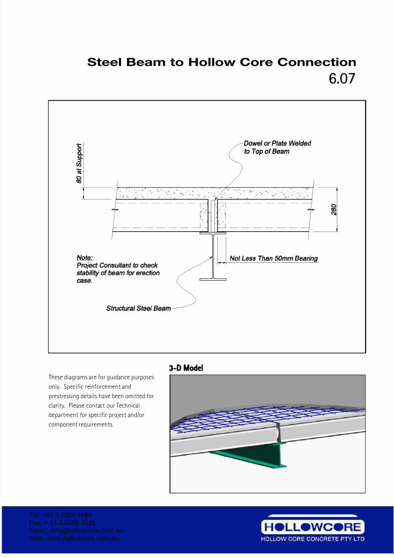
Steel Beam to Hollow Core Connection
6.07
3 D Model
These diagrams are for guidance purposes
only. Specific reinforcement and
prestressing details have been omitted for
clarity. Please contact our Technical
department for specific project and/or
component requirements.
Tel: +61 3 9369 4944Fax: + 61 3 9369 2025Email: [email protected] Web: www.hollowcore.com.au
7/26/2019 Hollow Core Concrete DetailingManual
http://slidepdf.com/reader/full/hollow-core-concrete-detailingmanual 39/41
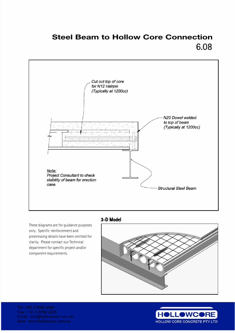
Steel Beam to Hollow Core Connection
6.08
3 D Model
These diagrams are for guidance purposes
only. Specific reinforcement and
prestressing details have been omitted for
clarity. Please contact our Technical
department for specific project and/or
component requirements.
Tel: +61 3 9369 4944Fax: + 61 3 9369 2025Email: [email protected] Web: www.hollowcore.com.au
7/26/2019 Hollow Core Concrete DetailingManual
http://slidepdf.com/reader/full/hollow-core-concrete-detailingmanual 40/41
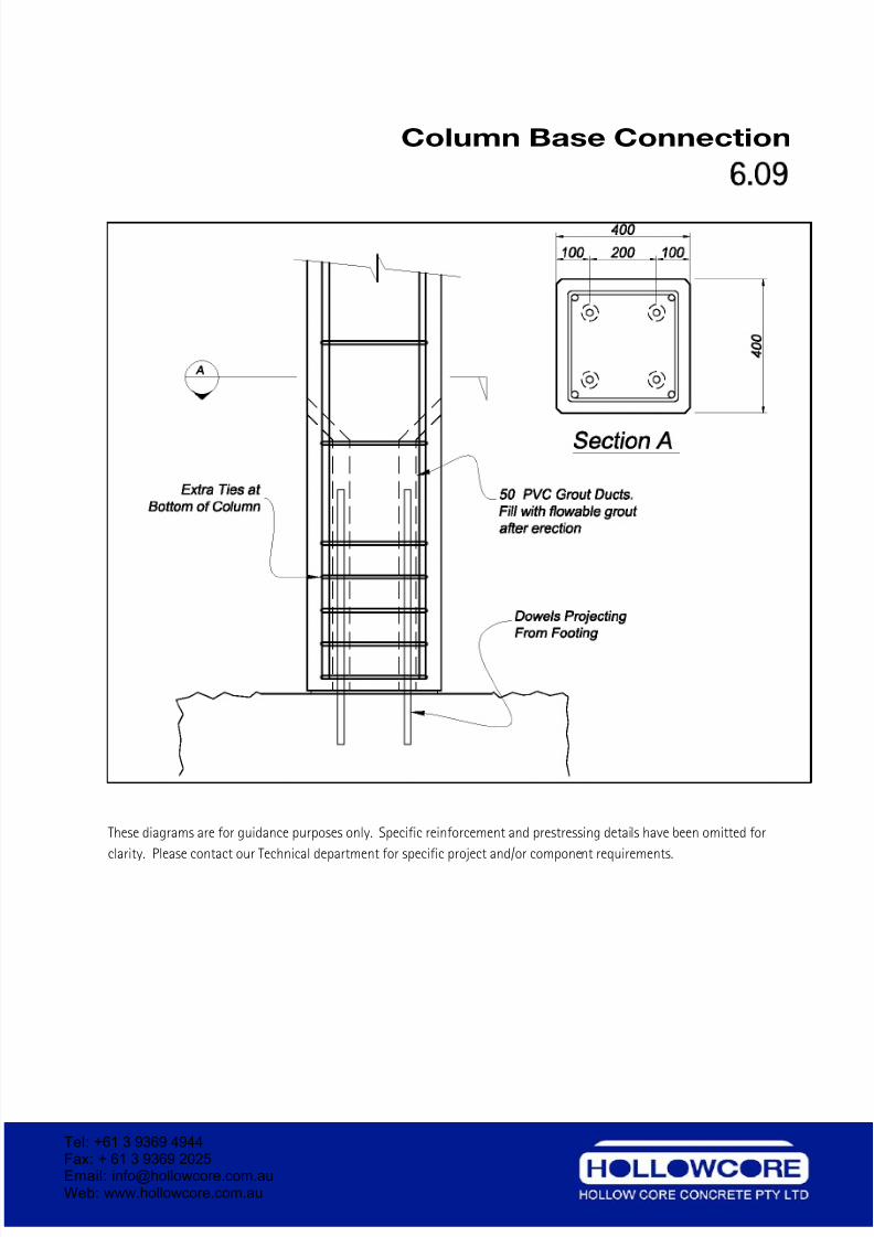
Column Base Connection
6 09
These diagrams are for guidance purposes only. Specific reinforcement and prestressing details have been omitted for
clarity. Please contact our Technical department for specific project and/or component requirements.
Tel: +61 3 9369 4944Fax: + 61 3 9369 2025Email: [email protected] Web: www.hollowcore.com.au
7/26/2019 Hollow Core Concrete DetailingManual
http://slidepdf.com/reader/full/hollow-core-concrete-detailingmanual 41/41