Embed Size (px)
Citation preview
World Housing Encyclopedia an Encyclopedia of Housing Construction in
Seismically Active Areas of the World
an initiative of Earthquake Engineering Research Institute (EERI) and
International Association for Earthquake Engineering (IAEE)
HOUSING REPORT Small concrete block masonry walls with concrete
floors and roofs
Report # 53
Report Date 05-06-2002
Country RUSSIAN FEDERATION
Housing Type Unreinforced Masonry Building
Housing Sub-Type Unreinforced Masonry Building : Concrete block masonry in cement mortar
Author(s) Mark Klyachko, Yuriy Gordeev, Freda Kolosova
Reviewer(s) Svetlana Uranova
Important This encyclopedia contains information contributed by various earthquake engineering professionalsaround the world. All opinions, findings, conclusions & recommendations expressed herein are those of thevarious participants, and do not necessarily reflect the views of the Earthquake Engineering ResearchInstitute, the International Association for Earthquake Engineering, the Engineering InformationFoundation, John A. Martin & Associates, Inc. or the participants' organizations.
Summary
This is a typical residential construction found both in urban and rural areas. It represents aconstruction practice followed in the former Soviet Union. Buildings of this type constitute 15to 30% of the housing stock in seismically prone areas of Russia (Far East, Siberia, Baikal
Lake Region, North Caucasus) and in CIS states (Central Asia, Armenia, Georgia, etc.). Themain load-bearing system for lateral and gravity loads consists of concrete block masonry wallsand concrete floor slabs. Seismic resistance is relatively good, provided that the welded blockwall connections are present and well constructed.
1. General Information
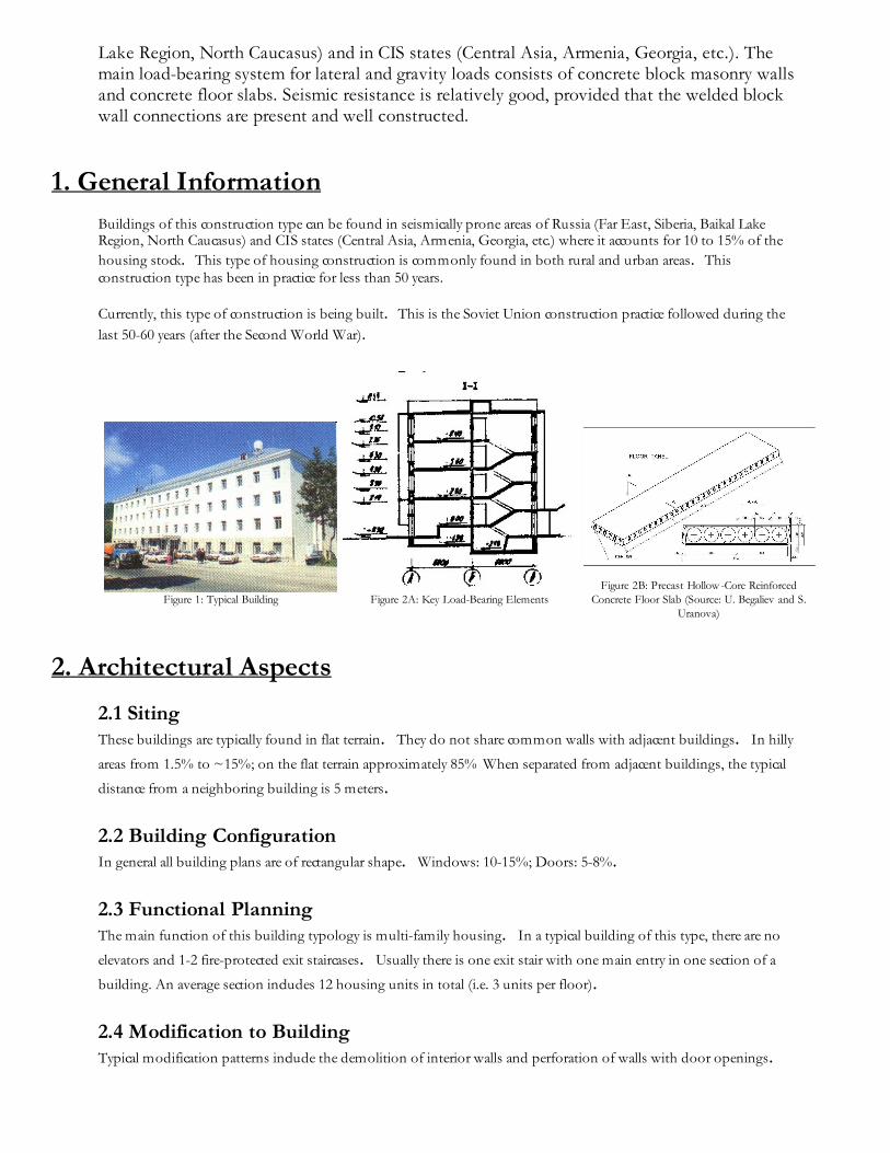
Buildings of this construction type can be found in seismically prone areas of Russia (Far East, Siberia, Baikal LakeRegion, North Caucasus) and CIS states (Central Asia, Armenia, Georgia, etc.) where it accounts for 10 to 15% of the
housing stock. This type of housing construction is commonly found in both rural and urban areas. Thisconstruction type has been in practice for less than 50 years.
Currently, this type of construction is being built. This is the Soviet Union construction practice followed during the
last 50-60 years (after the Second World War).
Figure 1: Typical Building
Figure 2A: Key Load-Bearing Elements
Figure 2B: Precast Hollow -Core ReinforcedConcrete Floor Slab (Source: U. Begaliev and S.
Uranova)
2. Architectural Aspects
2.1 Siting These buildings are typically found in flat terrain. They do not share common walls with adjacent buildings. In hilly
areas from 1.5% to ~15%; on the flat terrain approximately 85% When separated from adjacent buildings, the typical
distance from a neighboring building is 5 meters.
2.2 Building Configuration In general all building plans are of rectangular shape. Windows: 10-15%; Doors: 5-8%.
2.3 Functional Planning The main function of this building typology is multi-family housing. In a typical building of this type, there are no
elevators and 1-2 fire-protected exit staircases. Usually there is one exit stair with one main entry in one section of a
building. An average section includes 12 housing units in total (i.e. 3 units per floor).
2.4 Modification to Building Typical modification patterns include the demolition of interior walls and perforation of walls with door openings.
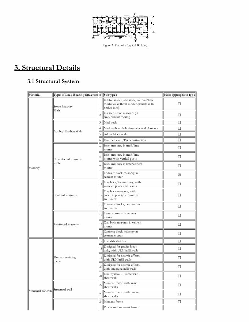
Figure 3: Plan of a Typical Building
3. Structural Details
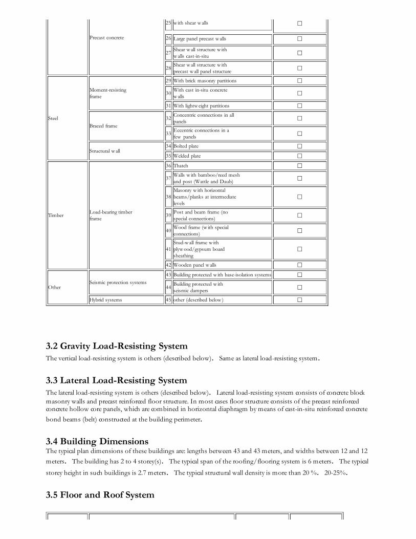
3.1 Structural System Material Type of Load-Bearing Structure # Subtypes Most appropriate type
Masonry
Stone Masonry Walls
1Rubble stone (field stone) in mud/lime mortar or w ithout mortar (usually w ith timber roof)
☐
2Dressed stone masonry (inlime/cement mortar)
☐
Adobe/ Earthen Walls
3 Mud w alls ☐
4 Mud w alls w ith horizontal w ood elements ☐
5 Adobe block w alls ☐
6 Rammed earth/Pise construction ☐
Unreinforced masonryw alls
7Brick masonry in mud/limemortar
☐
8Brick masonry in mud/limemortar w ith vertical posts ☐
9Brick masonry in lime/cementmortar
☐
10Concrete block masonry incement mortar
☑
Confined masonry
11Clay brick/tile masonry, w ithw ooden posts and beams
☐
12Clay brick masonry, w ithconcrete posts/tie columnsand beams
☐
13Concrete blocks, tie columnsand beams
☐
Reinforced masonry
14Stone masonry in cementmortar ☐
15Clay brick masonry in cementmortar ☐
16Concrete block masonry incement mortar ☐
Structural concrete
Moment resistingframe
17 Flat slab structure ☐
18Designed for gravity loadsonly, w ith URM infill w alls
☐
19Designed for seismic effects,w ith URM infill w alls ☐
20Designed for seismic effects,w ith structural infill w alls ☐
21Dual system – Frame w ithshear w all
☐
Structural w all
22Moment frame w ith in-situshear w alls ☐
23Moment frame w ith precastshear w alls ☐
24 Moment frame ☐Prestressed moment frame
Precast concrete
25 w ith shear w alls ☐
26 Large panel precast w alls ☐
27Shear w all structure w ithw alls cast-in-situ ☐
28Shear w all structure w ithprecast w all panel structure
☐
Steel
Moment-resistingframe
29 With brick masonry partitions ☐
30With cast in-situ concretew alls
☐
31 With lightw eight partitions ☐
Braced frame
32Concentric connections in allpanels ☐
33Eccentric connections in afew panels
☐
Structural w all34 Bolted plate ☐
35 Welded plate ☐
TimberLoad-bearing timberframe
36 Thatch ☐
37Walls w ith bamboo/reed meshand post (Wattle and Daub)
☐
38Masonry w ith horizontalbeams/planks at intermediatelevels
☐
39Post and beam frame (nospecial connections)
☐
40Wood frame (w ith specialconnections) ☐
41Stud-w all frame w ithplyw ood/gypsum boardsheathing
☐
42 Wooden panel w alls ☐
OtherSeismic protection systems
43 Building protected w ith base-isolation systems ☐
44Building protected w ithseismic dampers ☐
Hybrid systems 45 other (described below ) ☐
3.2 Gravity Load-Resisting System The vertical load-resisting system is others (described below). Same as lateral load-resisting system.
3.3 Lateral Load-Resisting System The lateral load-resisting system is others (described below). Lateral load-resisting system consists of concrete blockmasonry walls and precast reinforced floor structure. In most cases floor structure consists of the precast reinforcedconcrete hollow core panels, which are combined in horizontal diaphragm by means of cast-in-situ reinforced concrete
bond beams (belt) constructed at the building perimeter.
3.4 Building Dimensions The typical plan dimensions of these buildings are: lengths between 43 and 43 meters, and widths between 12 and 12
meters. The building has 2 to 4 storey(s). The typical span of the roofing/flooring system is 6 meters. The typical
storey height in such buildings is 2.7 meters. The typical structural wall density is more than 20 %. 20-25%.
3.5 Floor and Roof System
Material Description of floor/roof system Most appropriate floor Most appropriate roof
Masonry
Vaulted ☐ ☐
Composite system of concrete joists andmasonry panels
☐ ☐
Structural concrete
Solid slabs (cast-in-place) ☐ ☐
Waffle slabs (cast-in-place) ☐ ☐
Flat slabs (cast-in-place) ☐ ☐
Precast joist system ☐ ☐
Hollow core slab (precast) ☑ ☑
Solid slabs (precast) ☐ ☐Beams and planks (precast) w ith concretetopping (cast-in-situ) ☐ ☐
Slabs (post-tensioned) ☐ ☐
SteelComposite steel deck w ith concrete slab(cast-in-situ) ☐ ☐
Timber
Rammed earth w ith ballast and concrete orplaster finishing ☐ ☐
Wood planks or beams w ith ballast and concrete or plaster finishing ☐ ☐
Thatched roof supported on w ood purlins ☐ ☐
Wood shingle roof ☐ ☐
Wood planks or beams that support clay tiles ☐ ☐Wood planks or beams supporting naturalstones slates
☐ ☐
Wood planks or beams that support slate,metal, asbestos-cement or plastic corrugatedsheets or tiles
☐ ☐
Wood plank, plyw ood or manufactured w oodpanels on joists supported by beams or w alls
☐ ☐
Other Described below ☑ ☑
3.6 Foundation
Type Description Most appropriate type
Shallow foundation
Wall or column embedded insoil, w ithout footing
☐
Rubble stone, fieldstoneisolated footing ☐
Rubble stone, fieldstone stripfooting ☐
Reinforced-concrete isolatedfooting
☐
Reinforced-concrete stripfooting ☑
Mat foundation ☐
No foundation ☐
Deep foundation
Reinforced-concrete bearingpiles ☐
Reinforced-concrete skinfriction piles ☐
Steel bearing piles ☐
Steel skin friction piles ☐
Wood piles ☐
Cast-in-place concrete piers ☐
Caissons
☐
Other Described below ☐
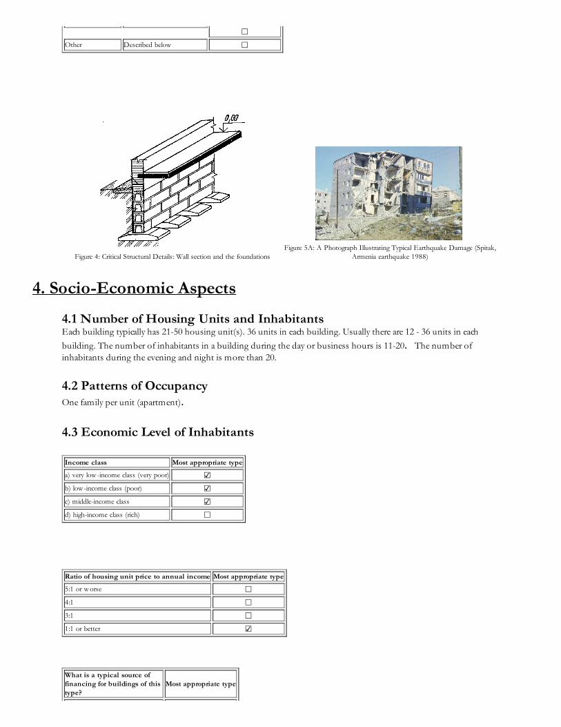
Figure 4: Critical Structural Details: Wall section and the foundations
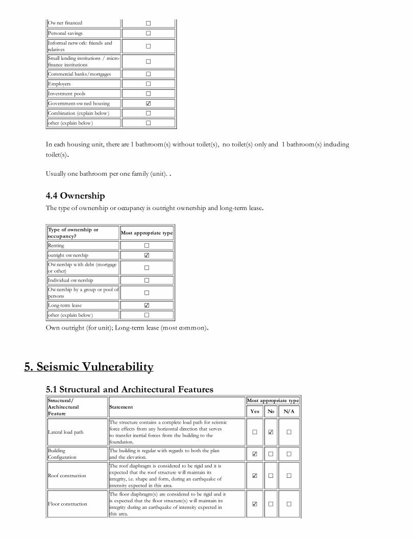
Figure 5A: A Photograph Illustrating Typical Earthquake Damage (Spitak,
Armenia earthquake 1988)
4. Socio-Economic Aspects
4.1 Number of Housing Units and Inhabitants Each building typically has 21-50 housing unit(s). 36 units in each building. Usually there are 12 - 36 units in each
building. The number of inhabitants in a building during the day or business hours is 11-20. The number ofinhabitants during the evening and night is more than 20.
4.2 Patterns of Occupancy One family per unit (apartment).
4.3 Economic Level of Inhabitants
Income class Most appropriate type
a) very low -income class (very poor) ☑
b) low -income class (poor) ☑
c) middle-income class ☑
d) high-income class (rich) ☐
Ratio of housing unit price to annual income Most appropriate type
5:1 or w orse ☐
4:1 ☐
3:1 ☐
1:1 or better ☑
What is a typical source offinancing for buildings of thistype?
Most appropriate type
Ow ner financed ☐
Personal savings ☐
Informal netw ork: friends andrelatives ☐
Small lending institutions / micro-finance institutions ☐
Commercial banks/mortgages ☐
Employers ☐
Investment pools ☐
Government-ow ned housing ☑
Combination (explain below ) ☐
other (explain below ) ☐
In each housing unit, there are 1 bathroom(s) without toilet(s), no toilet(s) only and 1 bathroom(s) including
toilet(s).
Usually one bathroom per one family (unit). .
4.4 Ownership The type of ownership or occupancy is outright ownership and long-term lease.
Type of ownership oroccupancy?
Most appropriate type
Renting ☐
outright ow nership ☑Ow nership w ith debt (mortgageor other) ☐
Individual ow nership ☐Ow nership by a group or pool ofpersons ☐
Long-term lease ☑
other (explain below ) ☐
Own outright (for unit); Long-term lease (most common).
5. Seismic Vulnerability
5.1 Structural and Architectural Features Structural/ArchitecturalFeature
StatementMost appropriate type
Yes No N/A
Lateral load path
The structure contains a complete load path for seismicforce effects from any horizontal direction that servesto transfer inertial forces from the building to thefoundation.
☐ ☑ ☐
BuildingConfiguration
The building is regular w ith regards to both the planand the elevation. ☑ ☐ ☐
Roof construction
The roof diaphragm is considered to be rigid and it isexpected that the roof structure w ill maintain itsintegrity, i.e. shape and form, during an earthquake ofintensity expected in this area.
☑ ☐ ☐
Floor construction
The floor diaphragm(s) are considered to be rigid and itis expected that the floor structure(s) w ill maintain itsintegrity during an earthquake of intensity expected inthis area.
☑ ☐ ☐
Foundationperformance
There is no evidence of excessive foundation movement(e.g. settlement) that w ould affect the integrity orperformance of the structure in an earthquake.
☑ ☐ ☐
Wall and framestructures-redundancy
The number of lines of w alls or frames in each principaldirection is greater than or equal to 2.
☑ ☐ ☐
Wall proportions
Height-to-thickness ratio of the shear w alls at each floor level is:
Less than 25 (concrete w alls);
Less than 30 (reinforced masonry w alls);
Less than 13 (unreinforced masonry w alls);
☑ ☐ ☐
Foundation-w allconnection
Vertical load-bearing elements (columns, w alls)are attached to the foundations; concretecolumns and w alls are dow eled into thefoundation.
☑ ☐ ☐
Wall-roofconnections
Exterior w alls are anchored for out-of-plane seismiceffects at each diaphragm level w ith metal anchors orstraps
☑ ☐ ☐
Wall openings
The total w idth of door and w indow openings in a w allis:
For brick masonry construction in cement mortar : lessthan ½ of the distance betw een the adjacent crossw alls;
For adobe masonry, stone masonry and brick masonryin mud mortar: less than 1/3 of the distance betw eenthe adjacent crossw alls;
For precast concrete w all structures: less than 3/4 ofthe length of a perimeter w all.
☑ ☐ ☐
Quality of building materialsQuality of building materials is considered to beadequate per the requirements of national codes andstandards (an estimate).
☐ ☑ ☐
Quality of w orkmanshipQuality of w orkmanship (based on visual inspection offew typical buildings) is considered to be good (perlocal construction standards).
☐ ☑ ☐
MaintenanceBuildings of this type are generally w ell maintained and thereare no visible signs of deterioration of buildingelements (concrete, steel, timber)
☐ ☑ ☐
Additional Comments
5.2 Seismic Features
StructuralElement
Seismic DeficiencyEarthquakeResilientFeatures
EarthquakeDamagePatterns
Wall - Absence of lime and plastifier; - Low cohesion of masonry (<120 kPa); (cohesion is equal to
tension strength of masonry w hen shear stress=0). - Low -strength masonry and cement mortar.
Frame(columns,beams)
Roof andfloors
-Floor slabs cannot be considered as rigid diaphragms due to poor quality of joints and connections.
Other
5.3 Overall Seismic Vulnerability Rating The overall rating of the seismic vulnerability of the housing type is B: MEDIUM-HIGH VULNERABILITY (i.e., poor
seismic performance), the lower bound (i.e., the worst possible) is B: MEDIUM-HIGH VULNERABILITY (i.e., poor
seismic performance), and the upper bound (i.e., the best possible) is C: MEDIUM VULNERABILITY (i.e., moderate
seismic performance).
Vulnerability high medium-high medium medium-low low very low
very poor poor moderate good very good excellent
VulnerabilityClass
A B C D E F
☐ ☑ ☑ ☐ ☐ ☐
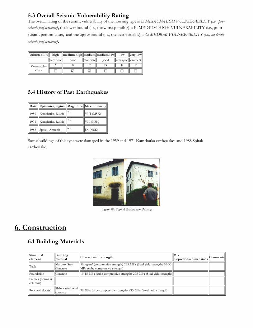
5.4 History of Past Earthquakes Date Epicenter, region Magnitude Max. Intensity
1959 Kamchatka, Russia 7.8 VIII (MSK)
1971 Kamchatka, Russia 7.2 VII (MSK)
1988 Spitak, Armenia 6.9 IX (MSK)
Some buildings of this type were damaged in the 1959 and 1971 Kamchatka earthquakes and 1988 Spitak
earthquake.
Figure 5B: Typical Earthquake Damage
6. Construction
6.1 Building Materials
Structuralelement
Buildingmaterial
Characteristic strengthMixproportions/dimensions
Comments
WallsMasonry SteelConcrete
50 kg/m² (compressive strength) 295 MPa (Steel yield strength) 20-30MPa (cube compressive strength)
Foundation Concrete 10-15 MPa (cube compressive strength) 295 MPa (Steel yield strength)
Frames (beams &columns)
Roof and floor(s)Slabs - reinforcedconcrete
30 MPa (cube compressive strength) 295 MPa (Steel yield strength)
6.2 Builder Buildings of this type were built by government-owned construction companies.
6.3 Construction Process, Problems and Phasing All precast structure members and concrete blocks are manufactured in special construction plants. Masonry mortar is
usually produced in the factory, too. Lifting crane is used for the erection of the building. The construction of this
type of housing takes place in a single phase. Typically, the building is originally designed for its final constructed
size.
6.4 Design and Construction Expertise Expertise for design of buildings of this type was available, including the construction quality procedure developed by
the author of this contribution. Design performed by Professional Engineers and Architects.
6.5 Building Codes and Standards This construction type is addressed by the codes/standards of the country. Building Catalog of Typical Project for
housing seria of 1-306c, 1-307c, 1957y. The year the first code/standard addressing this type of construction issued
was 1951. Construction in the Seismic Regions. SNiP II-7-81*. The most recent code/standard addressing this
construction type issued was 1981. Afterward numerous amendments were introduced. Title of the code orstandard: Building Catalog of Typical Project for housing seria of 1-306c, 1-307c, 1957y. Year the first code/standardaddressing this type of construction issued: 1951 National building code, material codes and seismic codes/standards:Construction in the Seismic Regions. SNiP II-7-81* When was the most recent code/standard addressing this
construction type issued? 1981. Afterward numerous amendments were introduced.
The process consists of issuing permits for the design and construction, including the architectural permits and urbanplanning/municipal permits. Designers need to have license to practice and are responsible to follow the building
codes. Building inspection is performed and the permit is issued.
6.6 Building Permits and Development Control Rules This type of construction is an engineered, and authorized as per development control rules. Building permits are
required to build this housing type.
6.7 Building Maintenance Typically, the building of this housing type is maintained by Owner(s). The maintenance is performed either by the
owner (city) or (periodically) by a contractor - a maintenance firm.
6.8 Construction Economics 250-350 $US/m² (per the official rate). It takes about 30 man-months to build a 4-story building with plan
dimensions 12m X 42m.
7. Insurance
Earthquake insurance for this construction type is typically available. For seismically strengthened existing buildingsor new buildings incorporating seismically resilient features, an insurance premium discount or more complete
coverage is unavailable. The insurance is available as a part of the usual property insurance. Insurance typically covers
about 3-5% of the total estimated property value.
8. Strengthening
8.1 Description of Seismic Strengthening Provisions
Strengthening of Existing Construction :
Seismic Deficiency Description of Seismic Strengthening provisions used
Inadequate seismic resistance of masonry
w alls The method of exterior frame - see Additional Comments
Inadequate seismic resistance of masonry
w alls Vertical post-tensioning; see Additional Comments and Figures 6A, 6B, and 6C
Inadequate seismic resistance of masonry
w alls The method of added stiffness (reinforced concrete overlay); see Additional Comments and Figures 6D
and 6E Inadequate seismic resistance of masonry
w alls Strengthening using the "Upper Damping Story" method
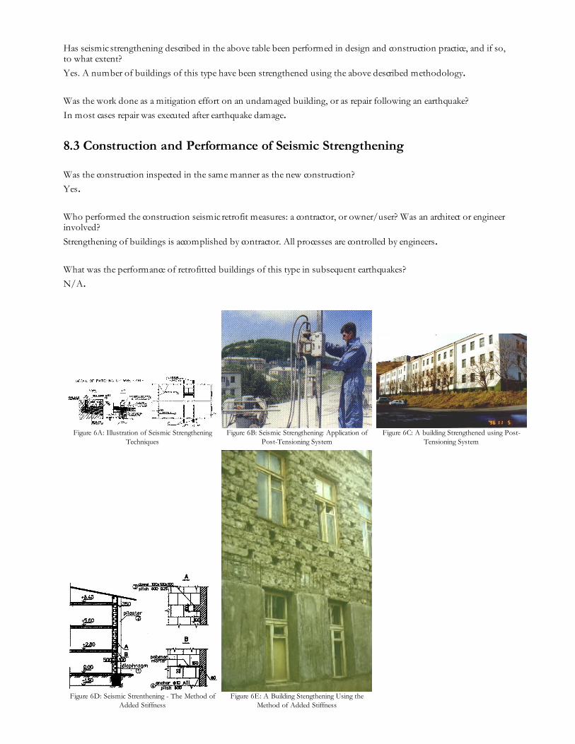
The recommended methods for seismic strengthening of buildings of this construction type are: METHOD OFEXTERIOR FRAME (MEF) - Goal: To increase lateral seismic stability of buildings with load-bearing masonry orlarge-block concrete walls. - Concept: The system of precast or "cast-in-situ" concrete buttresses (counterforts) (1) tiedto the longitudinal exterior wall. - Application: This method has been used successfully for seismic strengthening ofbuildings with longitudinal bearing walls and deficient lateral earthquake resistance both as self-containedstrengthening system and as a combination with PTS (for stringer walls) or with SIS (for extended masonry buildingswith widely spaced lateral inner walls) - Description: The MEF is performed by constructing special concrete buttresses(counterforts) tied to the longitudinal load-bearing walls at the building ends and other locations as required. In orderto ensure a uniform seismic performance of the existing structure strengthened with the buttresses, the buttresses aretied to the existing walls by means of the dowels and anchors. This solution does not require the pairs of buttresses(counterforts) to be tied at each floor level; it is considered to be adequate to install a prestressed tie to connect thebuttresses (counterforts) at the roof level. STRENGTHENING OF BUILDINGS USING THE POST -TENSIONING SYSTEM (PTS) - Goal: To increase seismic resistance of existing buildings. - Concept: The reductionin principal tensile stresses induced by seismic loads to allowable levels. - Description and sequence of operations: *Drilling of the vertical holes is carried out by means of special equipment; the amount of opening (10) is not less thanone for each partition. * The wire cables (2) are pulled through each opening (10) * Cables are anchored at thebasement level and then post-tensioned up to 1600 KN. * A special cement-based grout (1) is injected into the holesand the cables are subsequently anchored at the roof level. The post-tensioning of walls prevents the formation ofcracks in an earthquake and results in the increased seismic resistance of the individual walls and the building as awhole. - Equipment: For drilling: "GEARMEC" (Sweden); for post-tensioning: IMS system (Yugoslavia). THEMETHOD OF ADDED STIFFNESS (SIS) - Goal: Seismic strengthening of masonry buildings to achieve increasedseismic reliability and safety. - Concept: The stiffness increase is achieved by means of a new reinforced concrete wall(overlay) attached to the existing wall. In this way, the coupled perforated shear walls are formed, and lateral seismicloads are redistributed: the seismic loads remove on the spine walls from principal one. - Description: The SIS methodconsists of constructing new cast-in-situ concrete walls (1) of 10-15 cm thickness reinforced with steel wire mesh. Thenew walls are attached to the existing ones using dowels (3) and anchors (4). The new walls may be constructed withadditional pilasters (2) if required. - Equipment: Sheathing "MEVA" (Germany), instruments: "Bosch" and "Hilti"(Germany). THE METHOD OF UPPER DAMPING STOREY (UDS) - Goal: To develop a big mass damper forthe self-damping of buildings under seismic impact. - Concept: To achieve a flexible structure with stiffness and masscapable of reducing the seismic demand in an existing building to a permissible level. - Application: Masonry or blockbuildings with deficient seismic resistance D=2.0 (MSK scale). A very effective application for 4- to 5-story residentialmasonry and large-block houses with D=1.0-1.5. The superstructure can be constructed as a "cold" garret or as
additional floor (duplex apartment).
8.2 Seismic Strengthening Adopted
Has seismic strengthening described in the above table been performed in design and construction practice, and if so,to what extent?
Yes. A number of buildings of this type have been strengthened using the above described methodology.
Was the work done as a mitigation effort on an undamaged building, or as repair following an earthquake?
In most cases repair was executed after earthquake damage.
8.3 Construction and Performance of Seismic Strengthening
Was the construction inspected in the same manner as the new construction?
Yes.
Who performed the construction seismic retrofit measures: a contractor, or owner/user? Was an architect or engineerinvolved?
Strengthening of buildings is accomplished by contractor. All processes are controlled by engineers.
What was the performance of retrofitted buildings of this type in subsequent earthquakes?
N/A.
Figure 6A: Illustration of Seismic StrengtheningTechniques
Figure 6B: Seismic Strengthening: Application ofPost-Tensioning System
Figure 6C: A building Strengthened using Post-Tensioning System
Figure 6D: Seismic Strenthening - The Method ofAdded Stiffness
Figure 6E: A Building Stengthening Using theMethod of Added Stiffness
Reference(s)
1. Manual on Certification of Buildings and Structures in the Seismic-Prone Areas, Second EditionCENDR, Petropavlovsk, Kamchatka, Russia 1990
2. Recommendations for Preventive Seismic Strengthening of BuildingsCENDR, Russia 1993
Author(s)
1. Mark Klyachko
Director, Centre on EQE and NDR (CENDR)
9 Pobeda Avenue, Petropavlovsk Kamchatka 683006, RUSSIA
Email:[email protected] [email protected] FAX: +7(415)22-8774 +7(812)222-0676
2. Yuriy Gordeev
Head of Dept., Centre on EQE and NDR (CENDR)
9 Pobeda Avenue, Petropavlovsk Kamchatka 683006, RUSSIA
Email:[email protected] [email protected] FAX: +7(415)22-8774 +7(812)222-0676
3. Freda Kolosova
Professor, Centre on EQE and NDR (CENDR)
9 Pobeda Avenue, Petropavlovsk Kamchatka 683006, RUSSIA
Email:[email protected]; [email protected] FAX: +7(415)22-8774 +7(812)222-0676
Reviewer(s)1. Svetlana Uranova
Head of the Laboratory, KRSUBishkek 720000, KYRGYZSTANEmail:[email protected] FAX: 996-3312-282859
Save page as