Embed Size (px)
Citation preview
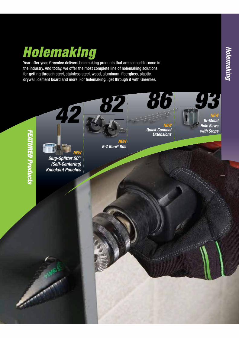
HolemakingYear after year, Greenlee delivers holemaking products that are second-to-none in the industry. And today, we offer the most complete line of holemaking solutions for getting through steel, stainless steel, wood, aluminum, fiberglass, plastic, drywall, cement board and more. For holemaking...get through it with Greenlee.
Holemaking
FEATURED Products
86NEW
Bi-Metal Hole Saws with Stops
42NEW
Slug-Splitter SC™ (Self-Centering)
Knockout Punches
82 93NEW
E-Z Bore® Bits
NEWQuick Connect
Extensions
BHowit
NEW
NEWQ i k C t

USA
Tel:
800
.435
.078
6
Fax:
800
.451
.263
2Ca
nada
Tel
: 80
0.43
5.07
86
Fax:
800
.524
.285
3In
tern
atio
nal
Tel:
+1.
815.
397.
7070
Fa
x: +
1.81
5.39
7.92
47
40
Hole
mak
ing
= REPLACEMENT PART = ACCESSORY
www.greenlee.com
Holemaking Selection Guide
MATERIAL NUMBER MATERIAL TYPE THICKNESS OF HOLES PRODUCTS APPLICATION CONSIDERATIONS PAGES
Steel 10GA Highest Slug-Splitter SC™ Punches Maximum durability and universal 42-44 material usage Maximum hole size 2-1/2 inches 10GA High Slug-Buster® Punches Maximum hole size 2-1/2 inches 45-51 10GA High Standard Punches Maximum hole size 5-5/8 inches 52-53 10GA Medium-High Ultra Cutters Maximum hole size 2-1/2 inches 90 8GA High Carbide-Tipped Hole Cutters Maximum hole size 2-1/2 inches 89 10GA Medium-High Step Bits Maximum hole size 1-3/8 inches 79 10GA Medium Hole Saws Maximum hole size 6 inches 91-97 Stainless Steel 10GA Highest Slug-Splitter SC™ Punches Maximum durability and universal material usage 42-44 Maximum hole size 2-1/2 inches 9GA Medium-High Quick Change Maximum hole size 3 inches, quick change 88 Carbide-Tipped Cutters cutting heads 8GA Medium-High Carbide-Tipped Hole Cutters Maximum hole size 2-1/2 inches 89 Wood 18" High Nail Eater II® Bits Cuts through nails, good chip removal, 80 max hole size 1-1/4 inches 2–2 x 4’s High E-Z Bore® Bits Self feed screw for hard or soft woods, 82 max hole size 4-5/8 inches 2 x 4 High Step Bits Maximum hole size 1-3/8 inches, low chip removal 79 16" Medium Spade Bits Maximum hole size 1-1/2 inches 83 1-5/8" or 2 x 4 High Hole Saws Maximum hole size 6 inches 91-97 Aluminum 10GA Highest Slug-Splitter SC™ Punches Maximum durability and universal material usage 42-44 Maximum hole size 2-1/2 inches 10GA High Slug-Buster® Punches Maximum hole size 2-1/2 inches 45-51 10GA High Standard Punches Maximum hole size 5-5/8 inches 52-53 10GA High Ultra Cutters Maximum hole size 2-1/2 inches 90 10GA High Step Bits Maximum hole size 1-3/8 inches 79 10GA Medium Hole Saws Maximum hole size 6 inches 91-97 Fiberglass/Plastic approx. 1/8" Highest Slug-Splitter SC™ Punches Maximum durability and universal material usage 42-43 Maximum hole size 2-1/2 inches approx. 1/8" High Slug-Buster® Punches Maximum hole size 2-1/2 inches 43-51 approx. 1/8" High Standard Punches Maximum hole size 5-5/8 inches 52-53 High Ultra Cutters Maximum hole size 2-1/2 inches 90 Medium-High Step Bits Maximum hole size 1-3/8 inches 79 1-5/8" Medium Hole Saws Maximum hole size 6 inches 91-97 Drywall/Ceiling Tile 7/8" High Recessed Light Hole Saws Replaceable blades 96 7/8" Medium-Low Quick Cutter Adjustable or fixed, sprinkler heads or lighting 96 7/8" Medium Keyhole Saw Non-round holes 100 Quazite®* Enclosures High Slug-Buster® Punches 45-51 approx. 1/8" High Carbide-Grit Hole Saws 93 Hardyboard Siding High Carbide-Grit Hole Saws 93 Cement Board High Carbide-Grit Hole Saws 93 Existing Wall D’versibits® Remodeling, phone, cable, alarm installation 84-85 Non-Round Hole High Non-Round Punches Square, rectangular, electronic connector holes 70-71 Medium Reciprocating Blades 98 Medium Jigsaw Blades 99 Non-Conduit Sizes 16-10GA High Standard Punches 52-56 Metal Studs 20GA Stud Punches 76-77
*Quazite is a registered trademark of Strongwell Corporation
SELECTION GUIDES
STEEL
STAINLESS STEEL
WOOD
ALUMINUM
FIBERGLASS
PLASTIC
DRYWALLCEILING TILES
NON-ROUND HOLE

41
USA Tel: 800.435.0786
Fax: 800.451.2632Canada Tel: 800.435.0786
Fax: 800.524.2853International Tel: +
1.815.397.7070
Fax: +1.815.397.9247
Holemaking
= REPLACEMENT PART = ACCESSORY
www.greenlee.com
Knockout Punch and Driver Selection Guide
PUNCH TYPE DRIVE METHOD CAPACITY SIZE RANGE AVAILABLE PAGES
Slug-Splitter SC™ Ratchet, Hydraulic or Battery Up thru 10 gauge (3.5 mm) .598" through 2.526" dia. 42-44 stainless steel or mild steel (15.2 mm through 64 mm)
Slug-Buster® Manual, Ratchet, Up thru 10 gauge .492" through 2.52" dia. 45-51 Hydraulic or Battery (3.5 mm) mild steel (12.5 mm through 64.0 mm)
Standard Round Manual, Ratchet, Up thru 10 gauge (3.5 mm) 1/2" through 5-5/8" dia. 52-56 Hydraulic or Battery mild steel and aluminum (12.7 through 143.7 mm)
DRIVER TYPE DESCRIPTION KITS PAGES
® knockout
Hydraulic Driver 115, 230 or 12 volt. punches.
with Greenlee standard and Slug-Buster® knockout punches and 12 gauge (2.5 mm) stainless steel with Greenlee Slug-Splitter SC™ knockout punches.
Hydraulic Driver hydraulic force. or with driver and either standard,
® or Slug-Splitter SC™ Greenlee standard and Slug-Buster® knockout knockout punches. punches and 10 gauge (3.5 mm) stainless steel with Greenlee Slug-Splitter SC™ knockout punches.
®
with Ram hydraulic force. or Slug-Splitter SC™ knockout punches.
with Greenlee Standard and Slug-Buster® knockout punches and 10 gauge (3.5 mm) stainless steel with Greenlee Slug-Splitter SC™ knockout punches.
Quick Draw® Hydraulic Driver to work area.
with Greenlee Standard and Slug-Buster® knockout punches and 10 gauge (3.5 mm) stainless steel with Greenlee Slug-Splitter SC™ knockout punches.
Quick Draw 90® Hydraulic Driver maximum flexibility in tight working areas. driver and Slug-Buster® knockout
with Greenlee Standard and Slug-Buster® knockout punches and 10 gauge (3.5 mm) stainless steel with Greenlee Slug-Splitter SC™ knockout punches.
Quick Draw® ® knockout
with Greenlee Standard and Slug-Buster® knockout punches and 10 gauge (3.5 mm) stainless steel with Greenlee Slug-Splitter SC™ knockout punches.
Ratchet Driver wrench method. driver and Slug-Buster® knockout
with Greenlee Standard Slug-Buster® knockout punches and 16 gauge (1.5 mm) stainless steel with Greenlee Slug-Splitter SC™ knockout punches.
Knockout Punch
Knockout Punch Driver
Hyd
with R
y
H
Q

USA
Tel:
800
.435
.078
6
Fax:
800
.451
.263
2Ca
nada
Tel
: 80
0.43
5.07
86
Fax:
800
.524
.285
3In
tern
atio
nal
Tel:
+1.
815.
397.
7070
Fa
x: +
1.81
5.39
7.92
47
42
Hole
mak
ing
= REPLACEMENT PART = ACCESSORY
www.greenlee.com
Slug is split in half as punching operation is completed.
Split slugs fall free from the die and stud.
Unique Slug-Splitter SC™ punch design creases slug as the punch is drawn into the die.
HOLE SIZE CAPACITY DRAW STUDS PUNCH DIE CONDUIT ACTUAL STAINLESS STEEL HYDRAULIC DRIVERS RATCHET DRIVER* CAT./UPC NO. CAT./UPC NO. & PIPE Ø (INCH) Ø (mm) PG ISO GA. (mm) 7804/7904 7646/7625 1904 28154 28155 1/2" 7/8 0.885 22.5 16 - 10 3.5 29451 29451 30227 28156 28157 3/4" - 1.115 28.3 21 - 10 3.5 31872 29452 12099 36490 36489 - 1-7/32 1.210 30.5 - - 10 3.5 31872 29452 12099 28158 28159 1" 1-11/32 1.352 34.6 - - 10 3.5 31872 29452 12099 28160 28161 1-1/4" 1-11/16 1.701 43.2 - - 10 3.5 31872 29452 12099 28162 28163 1-1/2" 1-15/16 1.951 49.6 - - 10 3.5 - 29452 12099 28165 28166 2" 2-3/8 2.416 61.5 - - 10 3.5 - 29452 12099
31117 31126 - - 0.598 15.2 9 - 12 2.5 29451 29451 30227 04599 04598 - - 0.638 16.2 - 16 12 2.5 29451 29451 30227 31119 31128 - - 0.732 18.6 11 - 12 2.5 29451 29451 30227 31120 31129 - - 0.803 20.4 13 20 12 2.5 29451 29451 30227 04602 04601 - - 1.000 25.4 - 25 10 3.5 31872 29452 30227 04605 04603 - - 1.280 32.5 - 32 10 3.5 31872 29452 12099 31122 31135 - - 1.457 37.0 29 - 10 3.5 31872 29452 12099 04608 04607 - - 1.595 40.5 - 40 10 3.5 31872 29452 12099 31123 31131 - - 1.850 47.0 36 - 10 3.5 - 29452 12099 04611 04609 - - 2.000 50.8 - 50 10 3.5 - 29452 12099 31124 31132 - - 2.125 54.0 42 - 10 3.5 - 29452 12099 31125 31133 - - 2.362 60.0 48 - 10 3.5 - 29452 12099 04614 04613 - - 2.520 64.0 - 63 10 3.5 - 29452 12099* 16 ga. stainless steel capacity with ratchet driver.
STANDARD SLUG-SPLITTER KNOCKOUT PUNCHES
SLUG-SPLITTER SC™ (SELF CENTERING) KNOCKOUT PUNCHES
SLUG-SPLITTER SC™ KNOCKOUTSSlug-Splitter SC™ (Self-Centering) Knockout Punches 0.598" to 2.520"
™ heavy-duty punches are designed to punch up through 10 gauge (3.5 mm) stainless steel.
gauge (3.5 mm) mild steel and stainless steel.™)
(Slug-Splitter SC™)
™punch units consist of: punch, die and draw stud. Check individual punch for specific capacity.
Self-centering Slug-Splitter SC™.
SPECIFICATIONS
Capacity Stainless steel up through 10 gauge (3.5 mm)Application 10-gauge stainless steel, mild steel, fiberglass and plastic enclosures.Hole Sizes Conduit Sizes - Hole size is outside diameter of US conduit sizes.
Example: 1/2" conduit size actually makes a 7/8" hole.Pg Sizes - European standard pipe sizes.ISO Sizes - International Standards Organization pipe sizes.
Operation Operate with battery, hydraulic or high leverage ratchet driver only.
Designed for stainless steel applications

43
USA Tel: 800.435.0786
Fax: 800.451.2632Canada Tel: 800.435.0786
Fax: 800.524.2853International Tel: +
1.815.397.7070
Fax: +1.815.397.9247
Holemaking
= REPLACEMENT PART = ACCESSORY
www.greenlee.com
PUNCH UNIT - INCLUDES PUNCH, DIE & DRAW
HOLE SIZECAPACITY
STAINLESS STEELWEIGHT DRIVER
DRAW STUD
Catalog No. UPC NoConduit and
Pipe Sizeø inch ø mm GA mm LBS. kg 1904 7804/7904
LS60*/CLC60
7646/7625
745R-1/2 30384 1/2" 7/8 22.5 16 1.5 .6 .27 x 30227
745H-1/2 29560 1/2" 7/8 22.5 10 3.5 .7 .32 x x x 29451740H-1-7/32 Oil Tight
29563- 1-7/32 30.5 10 3.5 1.2 .54 x x x 29452
745H-3/4 12318 3/4" 1-3/32 28.3 10 3.5 1.26 .57 x 29452
745H-1 12319 1" 1-11/32 34.6 10 3.5 1.51 .68 x 29452
745H-1-1/4 12320 1-1/4" 1-11/16 43.2 10 3.5 1.96 .89 x 29452
745H-1-1/2 12321 1-1/2" 1-15/16 49.6 10 3.5 2.49 1.13 x 29452
745H-2 12322 2" 2-3/8 61.5 10 3.5 3.69 1.67 x 29452
745M-15.2 12323 - 0.598 15.2 12 2.5 .98 .44 x 29451
745M-16.2 12324 - 0.638 16.2 12 2.5 .97 .44 x 29451
745M-18.6 12325 - 0.732 18.6 12 2.5 .98 .45 x 29451
745M-20.4 12326 - 0.803 20.4 12 2.5 .96 .44 x 29451
745M-25.4 12317 - 1.000 25.4 10 3.5 1.05 .48 x 29451
745M-32.5 12327 - 1.280 32.5 10 3.5 1.53 .69 x 29452
745M-37 12328 - 1.457 37 10 3.5 1.68 .76 x 29452
745M-40.5 12329 - 1.595 40.5 10 3.5 1.83 .83 x 29452
745M-47 12330 - 1.850 47 10 3.5 2.3 1.04 x 29452
745M-50.8 12331 - 2.000 50.8 10 3.5 2.91 1.32 x 29452
745M-54 12332 - 2.125 54 10 3.5 2.90 1.31 x 29452
745M-60 12333 - 2.362 60 10 3.5 3.63 1.65 x 29452
745M-64 12334 - 2.520 64 10 3.5 3.87 1.75 x 29452
PUNCH UNIT
* Battery-Powered or Corded Knockout Punch Driver

USA
Tel:
800
.435
.078
6
Fax:
800
.451
.263
2Ca
nada
Tel
: 80
0.43
5.07
86
Fax:
800
.524
.285
3In
tern
atio
nal
Tel:
+1.
815.
397.
7070
Fa
x: +
1.81
5.39
7.92
47
44
Hole
mak
ing
= REPLACEMENT PART = ACCESSORY
www.greenlee.com
Slug-Splitter SC™ Ram and Hand Pump Hydraulic Driver Punch Kits
SLUG-SPLITTER SC™ KNOCKOUT KITS
HOLE SIZE CAPACITY KIT CAT./UPC NO. CONDUIT & ACTUAL STAINLESS STEEL 744/ 7307/ 7506/ CAT. NO. UPC NO. DESCRIPTION PIPE SIZE Ø INCH Ø mm GA mm 29619 29528 30385 28154 28154 1/2" Conduit Size Punch 1/2" 7/8 .885 22.5 10 3.5 28155 28155 1/2" Conduit Size Die 1/2" 7/8 .885 22.5 10 3.5 28156 28156 3/4" Conduit Size Punch 3/4" — 1.115 28.3 10 3.5 28157 28157 3/4" Conduit Size Die 3/4" — 1.115 28.3 10 3.5 36490 36490 1-7/32" Punch Oiltight — 1-7/32 1.210 30.5 10 3.5 36489 36489 1-7/32" Die Oiltight — 1-7/32 1.210 30.5 10 3.5 28158 28158 1" Conduit Size Punch 1" 1-11/32 1.362 34.6 10 3.5 28159 28159 1" Conduit Size Die 1" 1-11/32 1.362 34.6 10 3.5 28160 28160 1-1/4" Conduit Size Punch 1-1/4" 1-11/16 1.701 43.2 10 3.5 28161 28161 1-1/4" Conduit Size Die 1-1/4" 1-11/16 1.701 43.2 10 3.5 28162 28162 1-1/2" Conduit Size Punch 1-1/2" 1-15/16 1.951 49.6 10 3.5 28163 28163 1-1/2" Conduit Size Die 1-1/2" 1-15/16 1.951 49.6 10 3.5 28165 28165 2" Conduit Size Punch 2" 2-3/8 2.416 61.5 10 3.5 28166 28166 2" Conduit Size Die 2" 2-3/8 2.416 61.5 10 3.5 29451 29451 7/16" x 4-1/4" Draw Stud 29452 29452 3/4" x 5-1/2" Draw Stud 29529 29529 Metal Case 19193 19193 Metal Case 31068 31068 Metal Case 746SS 30387 Ram (includes 1 each of the following 3 items) 54167 54167 1/4" Female Coupler 54168 54168 Dust Plug 15908 15908 Spacer Group (includes 1 each of the following 3 items) 1924AA 03248 Spacer-Short 1925AA 03249 Spacer-Medium 1926AA 06904 Spacer-Long 767 13284 Hydraulic Hand Pump 38316 38316 High Pressure Hose Unit–1/4" x 3' (includes 1 each of the following 3 items) 54169 54169 1/4" Male Coupler 54170 54170 Dust Cap 06302 06302 High Pressure Hose–1/4" x 3'
Punc
hes
and
Dies
Draw
Stu
ds a
nd M
isc.
7506 Punch Kit
744 Punch Kit (driver not included)
7307 Punch Kit (driver not included)
7506 Punch Kit
WEIGHT CAT. NO. UPC NO. DESCRIPTION LBS. kg. 744 29619 1/2" through 1-1/4" Conduit Size Slug-Splitter SC Knockout Punch Kit 5 2.3 7307 29528 1/2" through 2" Conduit Size Slug-Splitter SC™ Knockout Punch Kit 10.4 4.7 7506 30385 1/2" through 2" Conduit Size Slug-Splitter SC™ Knockout Punch Kit with Hydraulic Ram and Hand Pump 32 14.5
NOTE: See Slug-Splitter SC™ knockout punch units on page 42 for list of individual punches, dies and draw studs.
SPECIFICATIONS
Operation 7307/29528 - Quick Draw®, Quick Draw 90® and Quick Draw® Flex Hydraulic Drivers, Battery-Powered Drivers, 7646 and 7625 Ram-Type Drivers.744/29619 - Quick Draw®, Quick Draw 90® and Quick Draw® Flex Hydraulic Drivers, Battery-Powered Drivers, 7646 and 7625 Ram-Type Drivers.7506/30385 - Hydraulic Ram and Hand Pump included.
All Kits Feature:™ (Self Centering) knockout punches with capacities up through 10
gauge (3.5 mm) stainless steel. Refer to individual punch capacity ratings.™)
™)7506 Kit Features
maintenance jobs.
7307(driv
CONDUITC NO DESCRIPTION PIPE SIZ
Designed for stainless steel applications
™

45
USA Tel: 800.435.0786
Fax: 800.451.2632Canada Tel: 800.435.0786
Fax: 800.524.2853International Tel: +
1.815.397.7070
Fax: +1.815.397.9247
Holemaking
= REPLACEMENT PART = ACCESSORY
www.greenlee.com
CONDUIT & WEIGHT OF PUNCH UNIT PIPE SIZE HOLE SIZES PUNCH UNIT PUNCH ONLY DIE ONLY STUD ONLY CAT NO. UPC INCH MM LBS. G CAT NO. UPC CAT NO. UPC CAT NO. UPC 77U-1/2* 10801 1/2" .885 22.2 0.3 137 77P-1/2 11361 14722 14722 00042 00042 77P-1/2P* 11261 14722P* 01992 00042 00042 77U-3/4* 10802 3/4" 1.115 28.3 0.8 363 77P-3/4 11362 124AV 06972 294AVBB 04040 77-3/4P* 11262 124AVP* 01993 294AVBBP* 01987 10807* 10807 - 1.21 30.5 0.9 408 11357 11357 36278 36278 294AVBB 04040 77U-1* 10803 1" 1.362 34.6 1 454 77P-1 11363 126AV 04011 394AVBB 04040 77P-1P* 11263 126AVP* 01994 294AVBBP 01987 77U-1-1/4* 10804 1-1/4* 1.701 43.2 1.3 590 77P-1-1/4 11364 128AV 04013 294AVBB 04040 77P-1-1/4P* 11264 128AVP* 01995 294AVBBP* 01987 77U-1-1/2* 10805 1-1/2" 1.951 49.6 2.1 953 77P-1-1/2 11365 440AV 04061 304AVBB 04042 77P-1-1/2P* 11265 440AVP* 01996 304AVBBP* 01988 77U-2* 10806 2" 2.416 61.4 2.3 1043 77P-2 11366 442AV 04063 304AVBB 04042 77P-2P* 11266 442AVP* 01997 304AVBBP* 01988 10800 10800 1/2"-2" Kit - - - - - - - - - -
SLUG-BUSTER® KNOCKOUTSSlug-Buster SC® (Self-Centering)
CAT NO. UPC NO. DESCRIPTION CONDUIT SIZE HOLE SIZES
77P-1/2 11361 1/2" Punch Buster, SC 1/2" .88514722 14722 1/2" Die Rd. 1/2" .88577P-3/4 11362 3/4" Punch Buster, SC 3/4" 1.115124AV 06972 3/4" Die Rd. 3/4" 1.115
77P-1 11363 1" Punch Buster, SC 1" 1.362126AV 04011 1" Die Rd. 1" 1.36277P-1-1/4 11364 1-1/4" Punch Buster, SC 1-1/4" 1.701128AV 04013 1-1/4" Die Rd. 1-1/4" 1.70177P-1-1/2 11365 1-1/2" Punch Buster, SC 1-1/2" 1.951440AV 04061 1-1/2" Die Rd. 1-1/2" 1.95177P-2 11366 2" Punch Buster, SC 2" 2.416442AV 04063 2" Die Rd. 2" 2.416
10800 Slug-Buster SC® Knockout Kit Includes*POP Packaged
®

USA
Tel:
800
.435
.078
6
Fax:
800
.451
.263
2Ca
nada
Tel
: 80
0.43
5.07
86
Fax:
800
.524
.285
3In
tern
atio
nal
Tel:
+1.
815.
397.
7070
Fa
x: +
1.81
5.39
7.92
47
46
Hole
mak
ing
= REPLACEMENT PART = ACCESSORY
www.greenlee.com
= NEW PRODUCT
PUNCH UNIT REPLACEMENT PARTS
PUNCH UNIT INCLUDES HOLE SIZE CAPACITY REPLACEMENT PUNCH, DIE AND DRAW STUD CONDUIT & ACTUAL MILD STEEL WEIGHT REPLACEMENT PUNCH REPLACEMENT DIE MANUAL DRAW STUD
CAT. NO. UPC NO. PIPE SIZE Ø INCH Ø mm PG ISO GA. mm LBS. g CAT. NO. UPC NO. CAT. NO. UPC NO. CAT. NO. UPC NO.
06727 06727 — — 0.492 12.5 7 12 16 1.5 0.3 137 06728 06728 06729 06729 1675AV 04218 12356 12356 — 1/2 — 12.7 7 — 16 1.5 0.15 69 12360 12360 12358 12358 1675AV 04218 12357 12357 — 9/16 — 14.3 — — 16 1.5 0.16 73.5 12357 12357 12361 12361 1675AV 04218 7211EBB-15.2 31989 — — 0.598 15.2 9 — 14 2.0 0.3 137 31969 31969 32002 32002 00042 00042 35177 35177 — — 0.638 16.2 — 16 14 2.0 0.3 137 35163 35163 35162 35162 00042 00042
12335 12335 — 11/16 — 17.5 — — 14 2.0 0.3 177 12337 12337 12336 12336 00042 00042 7211EBB-18.6 31990 — — 0.732 18.6 11 — 14 2.0 0.3 137 31970 31970 32003 32003 00042 00042 12307 12307 — 3/4 — 19.1 — — 14 2.0 0.4 183 12306 12306 12305 12305 00042 00042 7211EBB-20.4 31991 — — 0.803 20.4 13 20 14 2.0 0.3 137 31971 31971 32004 32004 00042 00042 7211BB-1/2 31962 1/2" 7/8 0.885 22.5 16 — 10 3.5 0.3 137 721-1/2 31756 14722 14722 00042 00042 12338 12338 — 15/16 — 23.8 — — 14 2.0 0.5 253 12340 12340 12339 12339 00042 00042
1/2" 7/8 0.885 22.5 16 — 10 3.5 — — 721-1/2P 01980 14722P 01992 00042P 06678 35178 35178 — 1 1.000 25.4 — 25 14 2.0 0.5 227 35165 35165 35164 35164 00042P 06678
12341 12341 — 1-1/16 — 27 — — 14 2.0 0.6 261 12343 12343 12342 12342 00042 00042 7211BB-3/4 31963 3/4" — 1.115 28.3 — — 10 3.5 0.8 363 721-3/4 31757 124AV 06972 249AVBB 04040
3/4" — 1.115 28.3 — — 10 3.5 — — 721-3/4P 01981 124AVP 01993 249AVBBP 01987 7211EBB-28.3 31993 — — 1.115 28.3 21 — 14 2.0 0.5 227 31973 31973 32006 32006 00042 00042 60246 60246 — 1-7/32 1.210 30.5 — — 10 3.5 0.6 273 60237 60237 36278 36278 249AVBB 04040 36508 36508 — 1-7/32 1.210 30.5 — — 14 2.0 0.6 273 36284 36284 36279 36279 00042 00042 12308 12308 — 1-1/4 — 31.8 — — 16 1.5 0.7 326.5 12309 12309 12310 12310 00042 00042 35179 35179 — — 1.280 32.5 — 32 10 3.5 0.8 363 35169 35169 35168 35168 249AVBB 04040 12344 12344 — 1-5/16 — 33.4 — — 16 1.5 0.7 345 12346 12346 12345 12345 00042 00042 7211BB-1 31964 1" — 1.362 34.6 — — 10 3.5 1 454 721-1 31758 126AV 04011 249AVBB 04040 12304 12304 — 1-3/8 — 34.9 — — 10 3.0 1.1 507.5 12303 12303 12302 12302 04040 04040
1" — 1.362 34.6 10 — 10 3.5 — — 721-1P 01982 126AVP 01994 249AVBBP 01987 7211EBB-37 31995 — — 1.457 37.0 29 — 10 3.5 1.2 545 31975 31975 32008 32008 249AVBB 04040 12313 12313 — 1-1/2 — 38.1 — — 10 3.0 1.2 559 12312 12312 12311 12311 04040 04040 35180 35180 — — 1.595 40.5 — 40 10 3.5 1.2 545 35158 35158 35159 35159 249AVBB 04040 12347 12347 — 1-5/8 — 41.3 — — 10 3.0 1.3 610.25 12349 12349 12348 12348 04040 04040 7211BB-1-1/4 31965 1-1/4" — 1.701 43.2 — — 10 3.5 1.3 590 721-1-1/4 31759 128AV 04013 249AVBB 04040 12316 12316 — 1-3/4 — 44.5 — — 10 3.0 1.4 661.5 12315 12315 12314 12314 04040 04040
1-1/4" — 1.701 43.2 — — 10 3.5 — — 721-1-1/4P 01983 128AVP 01995 249AVBBP 01987 7211EBB-47 31996 — — 1.850 47.0 36 — 10 3.5 1.9 862 31976 31976 32009 32009 304AVBB 04042 12350 12350 — 1-7/8 — 47.6 — — 10 3.0 1.8 853.5 12354 12354 12352 12352 04042 04042 7211BB-1-1/2 31966 1-1/2" — 1.951 49.6 — — 10 3.5 2.1 953 721-1-1/2 31760 440AV 04061 304AVBB 04042
1-1/2" — 1.951 49.6 — — 10 3.5 — — 721-1-1/2P 01984 440AVP 01996 304AVBBP 01988 35181 35181 — 2 2.000 50.8 — 50 10 3.5 2.3 1043 35160 35160 35161 35161 304AVBB 04042 36171 36171 — 2-1/8 2.125 54.0 42 — 10 3.5 2.5 1134 36172 36172 36173 36173 304AVBB 04042
12351 12351 — 2-1/4 — 57.2 — — 10 3.0 2.9 1336 12355 12355 12353 12353 04042 04042 7211EBB-60 31998 — — 2.362 60.0 48 — 10 3.5 2.8 1270 31978 31978 32011 32011 304AVBB 04042 7211BB-2 31967 2" 2-3/8 2.416 61.5 — — 10 3.5 3.2 1452 721-2 31761 442AV 04063 304AVBB 04042
2" 2-3/8 2.416 61.5 — — 10 3.5 — — 721-2P 01985 442AVP 01997 304AVBBP 01988 35182 35182 — — 2.520 64.0 — 63 10 3.5 3.4 1542 35167 35167 35166 35166 304AVBB 04042
Individually Packaged in Point of Purchase clamshell for display opportunities
Slug-Buster® Knockout Punches 0.492" to 2.520"
® punches available in sizes up thru 2.52" (64.0 mm).®.
SPECIFICATIONS
Capacity Mild steel up through 10 gauge (3.5 mm).Application Punch mild steel, aluminum, fiberglass and plastic.Hole Sizes Conduit Sizes- Hole size is outside diameter of US conduit sizes. i.e 1/2"
conduit actually 7/8". Pg Sizes-European standard pipe sizes. ISO Sizes- International Standards Organization pipe sizes.
Operation
part of the driver kit.
Unique Slug-Buster® punch design creases slug as the punch is drawn into the die.
Slug is split in half as punching operation is completed.
Split slugs fall free from the die and stud.

47
USA Tel: 800.435.0786
Fax: 800.451.2632Canada Tel: 800.435.0786
Fax: 800.524.2853International Tel: +
1.815.397.7070
Fax: +1.815.397.9247
Holemaking
= REPLACEMENT PART = ACCESSORY
www.greenlee.com
Slug-Buster® Manual Knockout Kits
® knockout punches, packaged to meet the contractor’s needs.
SLUG-BUSTER® KNOCKOUT KITS
7237BB
CAPACITY MILD STEEL WEIGHT
CAT. NO. UPC NO. DESCRIPTION GA mm LBS. kg.
7235BB 32013 1/2" - 1-1/4" Conduit Size Manual 10 3.5 2.7 1.2 Slug-Buster® Knockout Punch Kit
7237BB 32014 1-1/2" and 2" Conduit Size Manual 10 3.5 5.2 2.4 Slug-Buster® Knockout Punch Kit
7235BB/32013 SLUG-BUSTER® KNOCKOUT PUNCH KIT INCLUDES
HOLE SIZE ACTUAL CAT. NO. UPC NO. DESCRIPTION Ø INCH Ø mm PG 721-1/2 31756 1/2" Conduit Size Punch 7/8 .885 22.5 16
14722 14722 1/2" Conduit Size Die 7/8 .885 22.5 16
00042 00042 Draw Stud–3/8" x 1-5/8"
721-3/4 31757 3/4" Conduit Size Punch — 1.115 28.3 —
124AV 06972 3/4" Conduit Size Die — 1.115 28.3 —
721-1 31758 1" Conduit Size Punch — 1.362 34.6 —
126AV 04011 1" Conduit Size Die — 1.362 34.6 —
721–1-1/4 31759 1-1/4" Conduit Size Punch — 1.701 43.2 —
128AV 04013 1-1/4" Conduit Size Die — 1.701 43.2 —
249AVBB 04040 Draw Stud–3/4" x 2-1/8"
31880 31880 Plastic Case
7237BB/32014 SLUG-BUSTER® KNOCKOUT PUNCH KIT INCLUDES
HOLE SIZE ACTUAL CAT. NO. UPC NO. DESCRIPTION Ø INCH Ø mm PG 721-1-1/2 31760 1-1/2" Conduit Size Punch — 1.951 49.6 —
440AV 04061 1-1/2" Conduit Size Die — 1.951 49.6 —
721-2 31761 2" Conduit Size Punch 2-3/8 2.416 61.5 —
442AV 04063 2" Conduit Size Die 2-3/8 2.416 61.5 —
304AVBB 04042 Draw Stud–3/4" x 2-15/16"
32012 32012 Plastic Case
7235BB
7237BB
7235BB
USA
Tel:
800
.435
.078
6
Fax:
800
.451
.263
2Ca
nada
Tel
: 80
0.43
5.07
86
Fax:
800
.524
.285
3In
tern
atio
nal
Tel:
+1.
815.
397.
7070
Fa
x: +
1.81
5.39
7.92
47
48
Hole
mak
ing
= REPLACEMENT PART = ACCESSORY
www.greenlee.com
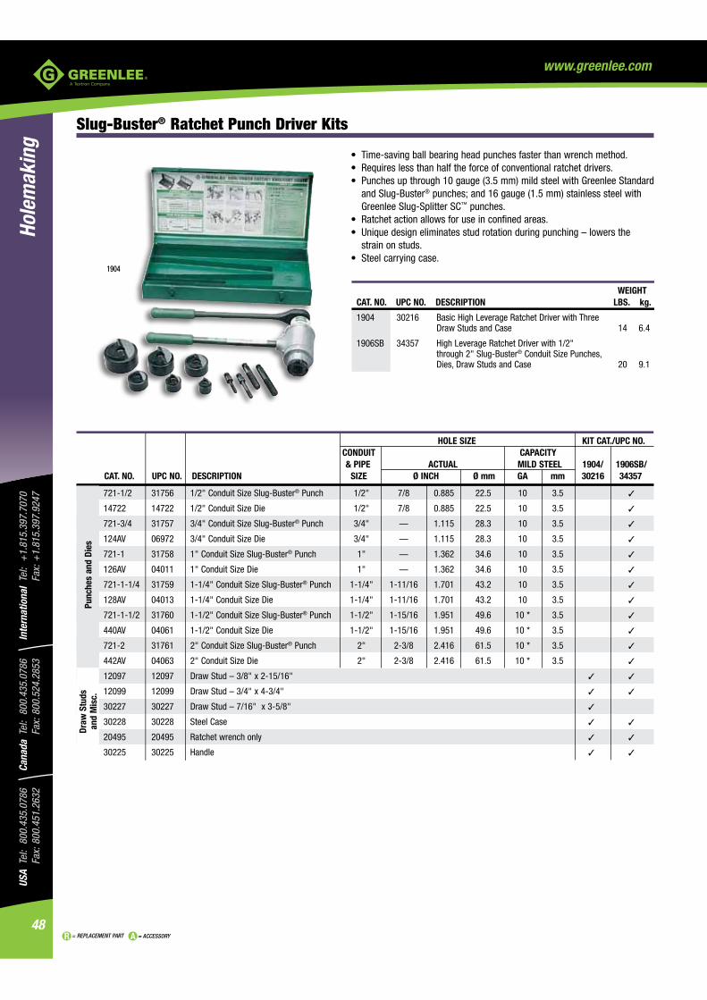
HOLE SIZE KIT CAT./UPC NO. CONDUIT CAPACITY & PIPE ACTUAL MILD STEEL 1904/ 1906SB/
CAT. NO. UPC NO. DESCRIPTION SIZE Ø INCH Ø mm GA mm 30216 34357
721-1/2 31756 1/2" Conduit Size Slug-Buster® Punch 1/2" 7/8 0.885 22.5 10 3.5
14722 14722 1/2" Conduit Size Die 1/2" 7/8 0.885 22.5 10 3.5
721-3/4 31757 3/4" Conduit Size Slug-Buster® Punch 3/4" — 1.115 28.3 10 3.5
124AV 06972 3/4" Conduit Size Die 3/4" — 1.115 28.3 10 3.5
721-1 31758 1" Conduit Size Slug-Buster® Punch 1" — 1.362 34.6 10 3.5
126AV 04011 1" Conduit Size Die 1" — 1.362 34.6 10 3.5
721-1-1/4 31759 1-1/4" Conduit Size Slug-Buster® Punch 1-1/4" 1-11/16 1.701 43.2 10 3.5
128AV 04013 1-1/4" Conduit Size Die 1-1/4" 1-11/16 1.701 43.2 10 3.5
721-1-1/2 31760 1-1/2" Conduit Size Slug-Buster® Punch 1-1/2" 1-15/16 1.951 49.6 10 * 3.5
440AV 04061 1-1/2" Conduit Size Die 1-1/2" 1-15/16 1.951 49.6 10 * 3.5
721-2 31761 2" Conduit Size Slug-Buster® Punch 2" 2-3/8 2.416 61.5 10 * 3.5
442AV 04063 2" Conduit Size Die 2" 2-3/8 2.416 61.5 10 * 3.5
12097 12097 Draw Stud – 3/8" x 2-15/16"
12099 12099 Draw Stud – 3/4" x 4-3/4"
30227 30227 Draw Stud – 7/16" x 3-5/8"
30228 30228 Steel Case
20495 20495 Ratchet wrench only
30225 30225 Handle
Punc
hes
and
Dies
Draw
Stu
ds
and
Mis
c.
WEIGHT CAT. NO. UPC NO. DESCRIPTION LBS. kg.
1904 30216 Basic High Leverage Ratchet Driver with Three Draw Studs and Case 14 6.4
1906SB 34357 High Leverage Ratchet Driver with 1/2" through 2" Slug-Buster® Conduit Size Punches, Dies, Draw Studs and Case 20 9.1
Slug-Buster® Ratchet Punch Driver Kits
and Slug-Buster®
Greenlee Slug-Splitter SC™ punches.
strain on studs.
1904

49
USA Tel: 800.435.0786
Fax: 800.451.2632Canada Tel: 800.435.0786
Fax: 800.524.2853International Tel: +
1.815.397.7070
Fax: +1.815.397.9247
Holemaking
= REPLACEMENT PART = ACCESSORY
www.greenlee.com
Slug-Buster® Knockout Kit with Ratchet Wrench
and 3/4" (19.1 mm) draw studs.
CAPACITY MILD STEEL WEIGHT
CAT. NO. UPC NO. DESCRIPTION GA mm LBS. kg.
7238SB 34757 1/2" – 2" Conduit Size Slug-Buster® Knockout Punch Kit 10 3.5 10 4.54
7238SB/34757 SLUG-BUSTER® KNOCKOUT PUNCH KIT INCLUDES
HOLE SIZE ACTUAL CAT. NO. UPC NO. DESCRIPTION Ø INCH Ø mm PG 34941 34941 Ratchet wrench – 1" Hex 721-1/2 31756 1/2" Conduit Size Punch 7/8 .885 22.5 16 14722 14722 1/2" Conduit Size Die 7/8 .885 22.5 16 721-3/4 31757 3/4" Conduit Size Punch — 1.115 28.3 — 124AV 06972 3/4" Conduit Size Die — 1.115 28.3 — 721-1 31758 1" Conduit Size Punch — 1.362 34.6 — 126AV 04011 1" Conduit Size Die — 1.362 34.6 — 721-1-1/4 31759 1-1/4" Conduit Size Punch — 1.701 43.2 — 128AV 04013 1-1/4" Conduit Size Die — 1.701 43.2 — 721-1-1/2 31760 1-1/2" Conduit Size Punch — 1.951 49.6 — 440AV 04061 1-1/2" Conduit Size Die — 1.951 49.6 — 721-2 31761 2" Conduit Size Punch 2-3/8 2.416 61.5 — 442AV 04063 2" Conduit Size Die 2-3/8 2.416 61.5 — 00042 00042 Ball Bearing Draw Stud with 1" Hex Head–3/8" x 1-5/8" 304AVBB 04042 Ball Bearing Draw Stud–3/4" x 2-15/16" 34758 34758 Plastic Case

USA
Tel:
800
.435
.078
6
Fax:
800
.451
.263
2Ca
nada
Tel
: 80
0.43
5.07
86
Fax:
800
.524
.285
3In
tern
atio
nal
Tel:
+1.
815.
397.
7070
Fa
x: +
1.81
5.39
7.92
47
50
Hole
mak
ing
= REPLACEMENT PART = ACCESSORY
www.greenlee.com
Slug-Buster® Knockout Kit with Ratchet Wrench - Metric
3/4" (19.1 mm) draw studs.® step bit included.
HOLE SIZE CAPACITY KIT CAT./UPC NO. ACTUAL MILD STEEL
CAT. NO. UPC NO. DESCRIPTION Ø INCH Ø mm PG ISO GA mm 36690 36691 36692 36693
31969 31969 Slug-Buster® Punch — 0.598 15.2 9 — 14 2.0
32002 32002 Die — 0.598 15.2 9 — 14 2.0
31970 31970 Slug-Buster® Punch — 0.732 18.6 11 — 14 2.0
32003 32003 Die — 0.732 18.6 11 — 14 2.0
31971 31971 Slug-Buster® Punch — 0.803 20.4 13 20 14 2.0
32004 32004 Die — 0.803 20.4 13 20 14 2.0
721-1/2 31756 Slug-Buster® Punch 7/8 0.885 22.5 16 — 10 3.5
14722 14722 Die 7/8 0.885 22.5 16 — 10 3.5
31973 31973 Slug-Buster® Punch — 1.115 28.3 21 — 14 2.0
32006 32006 Die — 1.115 28.3 21 — 14 2.0
36284 36284 30.5 mm Slug-Buster® Punch 1-7/32 1.210 30.5 — — 14 2.0
36279 36279 30.5 mm Die 1-7/32 1.210 30.5 — — 14 2.0
31975 31975 Slug-Buster® Punch — 1.457 37.0 29 — 10 3.5
32008 32008 Die — 1.457 37.0 29 — 10 3.5
31976 31976 Slug-Buster® Punch — 1.850 47.0 36 — 10 3.5
32009 32009 Die — 1.850 47.0 36 — 10 3.5
31978 31978 Slug-Buster® Punch — 2.362 60.0 48 — 10 3.5
32011 32011 Die — 2.362 60.0 48 — 10 3.5
35163 35163 ISO-16 Slug-Buster® Punch — 0.638 16.2 — 16 14 2.0
35162 35162 ISO-16 Die — 0.638 16.2 — 16 14 2.0
35165 35165 ISO-25 Slug-Buster® Punch 1 1.000 25.4 — 25 14 2.0
35164 35164 ISO-25 Die 1 1.000 25.4 — 25 14 2.0
35169 35169 ISO-32 Slug-Buster® Punch — 1.280 32.5 — 32 10 3.5
35168 35168 ISO-32 Die — 1.280 32.5 — 32 10 3.5
35158 35158 ISO-40 Slug-Buster® Punch — 1.595 40.5 — 40 10 3.5
35159 35159 ISO-40 Die — 1.595 40.5 — 40 10 3.5
35160 35160 ISO-50 Slug-Buster® Punch 2 2.000 50.8 — 50 10 3.5
35161 35161 ISO-50 Die 2 2.000 50.8 — 50 10 3.5
35167 35167 ISO-63 Slug-Buster® Punch 2-1/2 2.500 63.5 — 63 10 3.5
35166 35166 ISO-63 Die 2-1/2 2.500 63.5 — 63 10 3.5
249AVBB 04040 Draw Stud – 3/4" x 2-1/8"
304AVBB 04042 Draw Stud – 3/4" x 2-15/16"
36018 36018 Kwik Stepper® Step Bit 9.7 mm
34941
00042 00042 Ball Bearing Drive Nut with 1" Hex Head, 3/8" x 3"
36685 36685 Plastic Case
Draw
Stu
ds
and
Mis
c.Pu
nche
s an
d Di
es
36690
WEIGHT CAT. NO. UPC NO. DESCRIPTION LBS. kg. 36690 36690 Pg-9 through 30.5 mm Manual Slug-Buster® Metric Knockout Punch Kit 4.7 2.1 36691 36691 Pg-9 through Pg-48 and 30.5 mm Manual Slug-Buster® Metric Knockout Punch Kit 9 4.1 36692 36692 ISO-16 through ISO-40 Manual Slug-Buster®
Metric Knockout Punch Kit 5.6 2.5
36693 36693 ISO-16 through ISO-63 Manual Slug-Buster® Metric Knockout Punch Kit 9 4.1
690

51
USA Tel: 800.435.0786
Fax: 800.451.2632Canada Tel: 800.435.0786
Fax: 800.524.2853International Tel: +
1.815.397.7070
Fax: +1.815.397.9247
Holemaking
= REPLACEMENT PART = ACCESSORY
www.greenlee.com
Slug-Buster® Knockout Punch Kits for Ratchet/Hydraulic Drivers
HOLE SIZE CAPACITY- KIT CAT./UPC NO. CONDUIT & ACTUAL MILD STEEL 7216/ 7214E/ 7215E/
CAT. NO. UPC NO. DESCRIPTION PIPE SIZE Ø INCH Ø mm PG ISO GA mm 32017 32398 32803 35617 06892
721-1/2 31756 1/2" Conduit Size Punch 1/2" 7/8 .885 22.5 16 — 10 3.5
14722 14722 1/2" Conduit Size Die 1/2" 7/8 .885 22.5 16 — 10 3.5
721-3/4 31757 3/4" Conduit Size Punch 3/4" — 1.115 28.3 — — 10 3.5
124AV 06972 3/4" Conduit Size Die 3/4" — 1.115 28.3 — — 10 3.5
721-1 31758 1" Conduit Size Punch 1" — 1.362 34.6 — — 10 3.5
126AV 04011 1" Conduit Size Die 1" — 1.362 34.6 — — 10 3.5
721-1-1/4 31759 1-1/4" Conduit Size Punch 1-1/4" — 1.701 43.2 — — 10 3.5
128AV 04013 1-1/4" Conduit Size Die 1-1/4" — 1.701 43.2 — — 10 3.5
721-1-1/2 31760 1-1/2" Conduit Size Punch 1-1/2" — 1.951 49.6 — — 10 3.5
440AV 04061 1-1/2" Conduit Size Die 1-1/2" — 1.951 49.6 — — 10 3.5
721-2 31761 2" Conduit Size Punch 2" 2-3/8 2.416 61.5 — — 10 3.5
442AV 04063 2" Conduit Size Die 2" 2-3/8 2.416 61.5 — — 10 3.5
31969 31969 Punch — — .598 15.2 9 — 14 2.0
32002 32002 Die — — .598 15.2 9 — 14 2.0
31970 31970 Punch — — .732 18.6 11 — 14 2.0
32003 32003 Die — — .732 18.6 11 — 14 2.0
31971 31971 Punch — — .803 20.4 13 20 14 2.0
32004 32004 Die — — .803 20.4 13 20 14 2.0
31973 31973 Punch — — 1.115 28.3 21 — 14 2.0
32006 32006 Die — — 1.115 28.3 21 — 14 2.0
36284 36284 30.5 mm Punch — 1-7/32 1.210 30.5 — — 14 3.5
36279 36279 30.5 mm Die — 1-7/32 1.210 30.5 — — 14 3.5
31975 31975 Punch — — 1.457 37.0 29 — 10 3.5
32008 32008 Die — — 1.457 37.0 29 — 10 3.5
31976 31976 Punch — — 1.850 47.0 36 — 10 3.5
32009 32009 Die — — 1.850 47.0 36 — 10 3.5
31978 31978 Punch — — 2.362 60.0 48 — 10 3.5
32011 32011 Die — — 2.362 60.0 48 — 10 3.5
35163 35163 ISO-16 Punch — — 0.638 16.2 — 16 14 2.0
35162 35162 ISO-16 Die — — 0.638 16.2 — 16 14 2.0
35165 35165 ISO-25 Punch — 1 1.000 25.4 — 25 14 2.0
35164 35164 ISO-25 Die — 1 1.000 25.4 — 25 14 2.0
35169 35169 ISO-32 Punch — — 1.280 32.5 — 32 10 3.5
35168 35168 ISO-32 Die — — 1.280 32.5 — 32 10 3.5
35158 35158 ISO-40 Punch — — 1.595 40.5 — 40 10 3.5
35159 35159 ISO-40 Die — — 1.595 40.5 — 40 10 3.5
35160 35160 ISO-50 Punch — 2 2.000 50.8 — 50 10 3.5
35161 35161 ISO-50 Die — 2 2.000 50.8 — 50 10 3.5
35167 35167 ISO-63 Punch — — 2.520 64.0 — 63 10 3.5
35166 35166 ISO-63 Die — — 2.520 64.0 — 63 10 3.5
WEIGHT CAT. NO. UPC NO. DESCRIPTION LBS. kg.
7216 32017 1/2" - 2" Conduit Size Knockout Punch and Die Kit 5.5 2.5
7214E 32398 Pg-9 through 30.5 mm Slug-Buster® Pg Punch Kit 1.3 .6
7215E 32803 Pg-9 through Pg-48 and 30.5 mm Slug-Buster® 5.1 2.3 Pg Punch Kit
35617 35617 ISO-16 through ISO-40 Slug-Buster® ISO Punch Kit 1.6 .7
06892 06892 ISO-16 through ISO-63 Slug-Buster ® ISO Punch Kit 5.5 2.5
Ø INCHCONDUIT &&PIPE SIZE
HOL
T NO UPC NO DESCRIPTIONACT
C
7
7
7
3
0

USA
Tel:
800
.435
.078
6
Fax:
800
.451
.263
2Ca
nada
Tel
: 80
0.43
5.07
86
Fax:
800
.524
.285
3In
tern
atio
nal
Tel:
+1.
815.
397.
7070
Fa
x: +
1.81
5.39
7.92
47
52
Hole
mak
ing
= REPLACEMENT PART = ACCESSORY
www.greenlee.com
Standard Round Knockout Punches 0.5" to 5.675"
of punch, die and draw stud.
and accurate holes.
Punch
Die
Draw Stud
Bushing
Ball BearingNut
Every cut quick and clean ...Just tip it out.Slug falls free in die.
SPECIFICATIONS
Capacity Mild steel up through 10 gauge (3.5 mm).Application Punch mild steel, aluminum, fiberglass and plastic.Hole Sizes Conduit Sizes - Hole size is outside diameter of US conduit sizes.
Example: 1/2" conduit size punch actually makes a 7/8" hole. Pg Sizes - European standard pipe sizes. ISO Sizes - International Standards Organization pipe sizes.
Operation Operate with battery-powered, hydraulic, ratchet or manual drivers.
STANDARD KNOCKOUT PUNCHES

53
USA Tel: 800.435.0786
Fax: 800.451.2632Canada Tel: 800.435.0786
Fax: 800.524.2853International Tel: +
1.815.397.7070
Fax: +1.815.397.9247
Holemaking
= REPLACEMENT PART = ACCESSORY
www.greenlee.com
PUNCH UNIT REPLACEMENT PARTS
PUNCH KIT-INCLUDES HOLE SIZE CAPACITY REPLACEMENT REPLACEMENT PUNCH, DIE & DRAW STUD CONDUIT & ACTUAL MILD STEEL WEIGHT REPLACEMENT PUNCH REPLACEMENT DIE DRAW STUD BALL BEARING NUT CAT. NO. UPC NO. PIPE SIZE Ø INCH Ø mm PG ISO GA. mm LBS. g CAT. NO. UPC NO. CAT. NO. UPC NO. CAT. NO. UPC NO. CAT. NO. UPC NO.
730-1/2 024 08 — 1/2 0.500 12.7 7 — 16 1.5 .1 46 1760AV 06996 1759AV 04235 1675AV 04218 — —
730-9/16 02433 — 9/16 0.563 14.3 — — 16 1.5 .1 46 1754AV 04230 1753AV 04229 1675AV 04218 — —
21115 21115 — — 0.598 15.2 9 — 14 2.0 .3 137 21316 21316 32002 32002 00042 00042 — —
730-5/8 02409 — 5/8 0.625 15.9 — — 16 1.5 .2 91 1742AV 04223 1743AV 04224 1675AV 04218 — —
35192 35192 — — 0.638 16.2 — 16 14 2.0 .3 137 35193 35193 35162 35162 00042 00042 — —
730BB-11/16 25340 — 11/16 0.688 17.5 — — 14 2.0 .3 137 1752AV 04228 1751AV 04227 00042 00042 — —
730EBB-18.6 18886 — — 0.732 18.6 11 — 14 2.0 .3 137 17700 17700 32003 32003 00042 00042 — —
730BB-3/4 20667 — 3/4 0.750 19.1 — — 14 2.0 .3 137 113AV 03998 114AV 03999 00042 00042 — —
730EBB - 20.4 18887 — — 0.803 20.4 13 20 14 2.0 .3 137 17697 17697 32004 32004 00042 00042 — —
730BB-13/16 20668 — 13/16 0.812 20.6 — — 14 2.0 .3 137 1745AV 04226 1744AV 04225 00042 00042 — — 71BB 22563 1/2" 7/8 0.885 22.5 16 — 10 3.5 .4 182 121AV 04006 14722 14722 00042 00042 — —
730BB-15/16 25341 — 15/16 0.937 23.8 — — 14 2.0 .5 227 1762AV 04238 1761AV 04237 00042 00042 — — 730BB-1 20670 — 1 1.000 25.4 — 25 14 2.0 .5 227 87AV 03986 35164 35164 00042 00042 — — 730BB-1-1/16 25342 — 1-1/16 1.063 27.0 — — 14 2.0 .5 227 1763AV 04240 1764AV 04242 00042 00042 — — 72BB 22564 3/4" — 1.115 28.3 21 — 10 3.5 .9 409 123AV 04008 124AV 06972 249AVBB 04040 — —
36910 36910 3/4" — 1.115 28.3 21 — 14 2.0 .6 273 36882 36882 32006 32006 00042 00042 — —
730BB-1-1/8 20671 — 1-1/8 1.125 28.6 — — 14 2.0 .6 273 91AV 03990 92AV 03991 00042 00042 — — 36506 36506 — 1-7/32 1.210 30.5 — — 16 1.5 .6 273 36282 36282 36279 36279 00042 00042 — — 730BB-1-1/4 20673 — 1-1/4 1.250 31.8 — — 16 1.5 .7 318 117AV 04002 118AV 04003 00042 00042 — — 24476 24476 — — 1.280 32.5 — 32 10 3.5 1 454 24459 24459 35168 35168 249AVBB 04040 — —
730BB-1-5/16 25344 — 1-5/16 1.313 33.4 — — 16 1.5 .7 318 1747AV 06587 1746AV 06586 00042 00042 — —
73BB 22565 1" — 1.362 34.6 — — 10 3.5 1.1 499 125AV 04010 126AV 04011 249AVBB 04040 — —
730BB-1-3/8 25427 — 1-3/8 1.375 34.9 — — 10 3.5 1.1 499 3205AV 04734 3206AV 04735 249AVBB 04040 — —
730EBB-37 18890 — — 1.457 37.0 29 — 10 3.5 1 454 18331 18331 32008 32008 249AVBB 04040 — —
730BB-1-1/2 25428 — 1-1/2 1.500 38.1 — — 10 3.5 1.2 545 3207AV 04736 3208AV 07044 249AVBB 04040 — — 24477 24477 — — 1.595 40.5 — 40 10 3.5 1.3 590 24462 24462 35159 35159 249AVBB 04040 — —
730BB-1-5/8 25349 — 1-5/8 1.625 41.3 — — 10 3.5 1.4 636 1794AV 04251 1793AV 04250 249AVBB 04040 — —
74BB 22566 1-1/4" 1-11/16 1.701 43.2 — — 10 3.5 1.4 636 127AV 06974 128AV 04013 249AVBB 04040 — —
730BB-1-3/4 25350 — 1-3/4 1.750 44.5 — — 10 3.5 1.5 681 1816AV 04257 1815AV 04256 249AVBB 04040 — —
730EBB-47 18891 — — 1.850 47.0 — — 10 3.5 1.7 772 17687 17687 32009 32009 304AVBB 04042 — —
730BB-1-7/8 25351 — 1-7/8 1.875 47.6 — — 10 3.5 1.9 862 1791AV 04248 1792AV 04249 304AVBB 04042 — — 75BB 22567 1-1/2" 1-15/16 1.951 49.6 — — 10 3.5 2 908 439AV 06978 440AV 04061 304AVBB 04042 — —
730BB-2 20676 — 2 2.000 50.8 — 50 10 3.5 1.9 862 1756AV 04232 35161 35161 304AVBB 04042 — —
730BB-2-1/8 20678 — 2-1/8 2.125 54.0 42 — 10 3.5 2.2 998 1783AV 04245 36173 36173 304AVBB 04042 — —
730BB-2-1/4 25360 — 2-1/4 2.250 57.2 — — 10 3.5 2.6 1180 437AV 04058 438AV 04059 304AVBB 04042 — —
730EBB-60 18892 — — 2.362 60.0 48 — 10 3.5 2.6 1180 17690 17690 32011 32011 304AVBB 04042 — —
76BB 22568 2" 2-3/8 2.416 61.5 — — 10 3.5 3 1361 441AV 04062 442AV 04063 304AVBB 04042 — —
730BB-2-1/2 20679 — 2-1/2 2.500 63.5 — 63 10 3.5 3 1361 1758AV 04234 1757AV 04233 304AVBB 04042 — — 730PBB-2-5/8 21214 — 2-5/8 2.625 66.7 — — 10 3.5 5.1 2314 1795AV 04252 1796AV 06997 1434AV 04188 1433AVBB 04187
730BB-2-3/4 25361 — 2-3/4 2.750 69.9 — — 10 3.5 4.8 2178 1790AV 04247 1789AV 04246 1434AV 04188 1433AVBB 04187
730MBB 25383 — — 2.781 70.6 — — 10 3.5 3.8 1724 730101A 02445 730100A 02443 304AVBB 04042 — —
738BB 19975 2-1/2" 2-7/8 2.914 74.0 — — 10 3.5 5 2268 1429AV 04175 1430AV 04177 1434AV 04188 1433AVBB 04187
730BB-3 25372 — 3 3.000 76.2 — — 10 3.5 6.1 2767 1821AV 04259 1820AV 04258 1434AV 04188 1433AVBB 04187
730TBB 25403 — 3-1/8 3.125 79.4 — — 10 3.5 6 2722 1798AV 06363 1797AV 06362 1434AV 04188 1433AVBB 04187
730EBB-82 18635 — — 3.228 82.0 — — 10 3.5 6.3 2858 18905 18905 18906 18906 1434AV 04188 1433AVBB 04187
739BB 19976 3" 3-1/2 3.539 89.9 — — 10 3.5 5.9 2677 1431AV 04180 1432AV 04183 1434AV 04188 1433AVBB 04187
730PBB-3-3/4 21216 — 3-3/4 3.750 95.3 — — 10 3.5 7.7 3493 4640AV 05265 4641AV 05266 1434AV 04188 1433AVBB 04187
741BB* 19977 3-1/2" 4 4.044 102.7 — — 10 3.5 10 4536 2982AV 04653 2981AV 04652 3026AV 04679 3036AVBB 04685
742BB* 19978 4" 4-1/2 4.544 115.4 — — 10 3.5 11.4 5172 2984AV 04655 2983AV 04654 3026AV 04679 3036AVBB 04685
730EBB-120* 21519 — — 4.724 120.0 — — 10 3.5 13 5897 21489 21489 21491 21491 3026AV 04679 3036AVBB 04685
743BB* 19980 5" 5-5/8 5.675 144.1 — — 10 3.5 19 8619 5135AV 05447 5136AV 05448 3026AV 04679 3036AVBB 04685
*CAT. NO. UPC NO. DESCRIPTION
3037AV O4686 Bushing for 3-1/2" (conduit hole size) and larger punches with manual operation
Standard Round Knockout Punches
USA
Tel:
800
.435
.078
6
Fax:
800
.451
.263
2Ca
nada
Tel
: 80
0.43
5.07
86
Fax:
800
.524
.285
3In
tern
atio
nal
Tel:
+1.
815.
397.
7070
Fa
x: +
1.81
5.39
7.92
47
54
Hole
mak
ing
= REPLACEMENT PART = ACCESSORY
www.greenlee.com
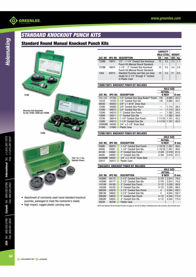
Standard Round Manual Knockout Punch Kits
735BB
737BB
punches, packaged to meet the contractor’s needs.
7304 For 11 Ton Hydraulic Drivers
CAPACITY MILD STEEL WEIGHT CAT. NO. UPC NO. DESCRIPTION GA mm LBS. kg. 735BB 19973 1/2" - 1-1/4" Conduit Size Knockout 10 3.5 2.5 1.1 Punch Kit (Manual Round Standard) 737BB 19974 1-1/2" - 2" Conduit Size Knockout 10 3.5 4.4 2.0 Punch Kit (Manual Round Standard) 7304 02815 Standard Punches and Dies (no draw 10 3.5 21 9.5 studs) for 2-1/2" through 4" Conduit, in Plastic Case
735BB/19973 KNOCKOUT PUNCH KIT INCLUDES HOLE SIZE ACTUAL CAT. NO. UPC NO. DESCRIPTION Ø INCH Ø mm 721-1/2 31756 1/2" Conduit Size Slug-Buster® Punch 7/8 0.885 22.5 14722 14722 1/2" Conduit Size Die 7/8 0.885 22.5 00042 00042 3/8" x 1-9/16" Draw Stud 123AV 04008 3/4" Conduit Size Punch — 1.115 28.3 124AV 06972 3/4" Conduit Size Die — 1.115 28.3 125AV 04010 1" Conduit Size Punch — 1.362 34.6 126AV 04011 1" Conduit Size Die — 1.362 34.6 127AV 06974 1-1/4" Conduit Size Punch 1-11/16 1.701 43.2 128AV 04013 1-1/4" Conduit Size Die 1-11/16 1.701 43.2 249AVBB 04040 3/4" x 2-1/8" Draw Stud 31880 31880 Plastic Case
737BB/19974 KNOCKOUT PUNCH KIT INCLUDES HOLE SIZE ACTUAL
CAT. NO. UPC NO. DESCRIPTION Ø INCH Ø mm 439AV 06978 1-1/2" Conduit Size Punch 1-15/16 1.951 49.6 440AV 04061 1-1/2" Conduit Size Die 1-15/16 1.951 49.6 441AV 04062 2" Conduit Size Punch 2-3/8 2.416 61.5 442AV 04063 2" Conduit Size Die 2-3/8 2.416 61.5 304AVBB 04042 3/4" x 2-15/16" Draw Stud 32012 32012 Plastic Case
7304/02815 KNOCKOUT PUNCH KIT INCLUDES HOLE SIZE ACTUAL CAT. NO. UPC NO. DESCRIPTION Ø INCH Ø mm 1429AV 04175 2-1/2" Conduit Size Punch 2-7/8 2.914 74.0 1430AV 04177 2-1/2" Conduit Size Die 2-7/8 2.914 74.0 1431AV 04180 3" Conduit Size Punch 3-1/2 3.539 89.9 1432AV 04183 3" Conduit Size Die 3-1/2 3.539 89.9 2982AV 04978 3-1/2" Conduit Size Punch 4 4.044 102.7 2981AV 04652 3-1/2" Conduit Size Die 4 4.044 102.7 2984AV 04655 4" Conduit Size Punch 4-1/2 4.544 115.4 2983AV 04654 4" Conduit Size Die 4-1/2 4.544 115.4 30236 30236 Plastic CaseNOTE: See Standard Round Knockout Punches on pages 52 and 53 for listing of individual punch units, punches, dies and draw studs.
STANDARD KNOCKOUT PUNCH KITS
55BB
7304 For 11 TonHydraulic Drivers
737BB
Wrenches Sold Separately for kits 737BB, 735BB and 7304BB

55
USA Tel: 800.435.0786
Fax: 800.451.2632Canada Tel: 800.435.0786
Fax: 800.524.2853International Tel: +
1.815.397.7070
Fax: +1.815.397.9247
Holemaking
= REPLACEMENT PART = ACCESSORY
www.greenlee.com
39860 MANUAL INDUSTRIAL KNOCKOUT PUNCH KIT INCLUDES
HOLE SIZE ACTUAL CAT. NO. UPC NO. DESCRIPTION Ø INCH Ø mm
113AV 03998 3/4" Punch 3/4 0.750 19.1 114AV 03999 3/4" Die 3/4 0.750 19.1
121AV 04006 7/8" Punch 7/8 0.885 22.5 14722 14722 7/8" Die 7/8 0.885 22.5
87AV 03986 1" Punch 1 1.000 25.4 35164 35164 1" Die 1 1.000 25.4
91AV 03990 1-1/8" Punch 1-1/8 1.125 28.6 92AV 03991 1-1/8" Die 1-1/8 1.125 28.6
117AV 04002 1-1/4" Punch 1-1/4 1.250 31.8 118AV 04003 1-1/4" Die 1-1/4 1.250 31.8
3207AV 04736 1-1/2" Punch 1-1/2 1.500 38.1 3208AV 07044 1-1/2" Die 1-1/2 1.500 38.1
00042 00042 3/8" BB Draw Stud 249AVBB 04040 3/4" BB Draw Stud
19193 19193 Steel Storage Box
Wrench Sold Separately
Standard Round Manual Industrial Punch Kit
with ratchet and hydraulic drivers.
CAT. NO. UPC NO. DESCRIPTION
39860 39860 3/4" - 1-1/2" Hole Size Manual Industrial Punch Kit
SPECIFICATIONS
Capacity 1-1/4" Punch - 16 gauge (1.5 mm) mild steel. 3/4", 1", and 1-1/8" Punches - 14 gauge (2.0 mm) mild steel. 7/8" and 1-1/2" Punches 10 gauge (3.5 mm) mild steel.
Operation
Wrench Sold Separately

USA
Tel:
800
.435
.078
6
Fax:
800
.451
.263
2Ca
nada
Tel
: 80
0.43
5.07
86
Fax:
800
.524
.285
3In
tern
atio
nal
Tel:
+1.
815.
397.
7070
Fa
x: +
1.81
5.39
7.92
47
56
Hole
mak
ing
= REPLACEMENT PART = ACCESSORY
www.greenlee.com
HOLE SIZE CAPACITY KIT CAT./UPC NO. ACTUAL MILD STEEL 7309E
CAT. NO. UPC NO. DESCRIPTION Ø INCH Ø mm PG ISO GA mm 36687 36688 32804
21316 21316 Pg-9 Punch — 0.598 15.2 9 — 14 2.0 31969 31969 Pg-9 Slug-Buster® Punch — 0.598 15.2 9 — 14 2.0 32002 32002 Pg-9 Die — 0.598 15.2 9 — 14 2.0 17700 17700 Pg-11 Punch — 0.732 18.6 11 — 14 2.0 32003 32003 Pg-11 Die — 0.732 18.6 11 — 14 2.0 17697 17697 Pg-13 Punch — 0.803 20.4 13 20 14 2.0 32004 32004 Pg-13 Die — 0.803 20.4 13 20 14 2.0 121AV 04006 Pg-16 Punch 7/8 0.885 22.5 16 — 10 3.5 14722 14722 Pg-16 Die 7/8 0.885 22.5 16 — 10 3.5 36882 36882 Pg-21 Punch — 1.115 28.3 21 — 10 3.5 32006 32006 Pg-21 Die — 1.115 28.3 21 — 10 3.5 36282 36282 30.5 mm Punch 1-7/32 1.210 30.5 — — 16 1.5 36279 36279 30.5 mm Die 1-7/32 1.210 30.5 — — 16 1.5 18331 18331 Pg-29 Punch — 1.457 37.0 29 — 10 3.5 32008 32008 Pg-29 Die — 1.457 37.0 29 — 10 3.5 17687 17687 Pg-36 Punch — 1.850 47.0 36 — 10 3.5 32009 32009 Pg-36 Die — 1.850 47.0 36 — 10 3.5 17690 17690 Pg-48 Punch — 2.362 60.0 48 — 10 3.5 32011 32011 Pg-48 Die — 2.362 60.0 48 — 10 3.5 35193 35193 ISO-16 Punch — 0.638 16.2 — 16 14 2.0 35162 35162 ISO-16 Die — 0.638 16.2 — 16 14 2.0 87AV 03986 ISO-25 Punch 1 1.000 25.4 — 25 14 2.0 35164 35164 ISO-25 Die 1 1.000 25.4 — 25 14 2.0 24459 24459 ISO-32 Punch — 1.280 32.5 — 32 10 3.5 35168 35168 ISO-32 Die — 1.280 32.5 — 32 10 3.5 24462 24462 ISO-40 Punch — 1.595 40.5 — 40 10 3.5 35159 35159 ISO-40 Die — 1.595 40.5 — 40 10 3.5 1756AV 04232 ISO-50 Punch 2 2.000 50.8 — 50 10 3.5 35161 35161 ISO-50 Die 2 2.000 50.8 — 50 10 3.5 1758AV 04234 ISO-63 Punch 2-1/2 2.500 63.5 — 63 10 3.5 1757AV 04233 ISO-63 Die 2-1/2 2.500 63.5 — 63 10 3.5 249AVBB 04040 Draw Stud – 3/4" x 2-1/8" 304AVBB 04042 Draw Stud – 3/4" x 2-15/16" 34941 34410 34410 Kwik Stepper® Step Bit 1/2" (12.7 mm) 00042 00042 Ball Bearing Draw Stud with 1" Hex Head, 3/8" x 1-5/8" 36685 36685 Plastic Case
Punc
hes
and
Dies
Draw
Stu
ds
and
Mis
c.
Standard Round Manual Knockout Punch Kits - Metric
WEIGHT CAT. NO. UPC NO. DESCRIPTION LBS. kg.
36687 36687 Pg-9 through Pg-48 Manual Round 8.8 4 Standard Knockout Punch Kit 36688 36688 ISO-16 through ISO-40 Manual 5.2 2.3 Round Standard Knockout Punch Kit 7309E 32804 Pg-9 through Pg-48 Standard 8.8 4 Knockout Pg. Punch Kit. Replacement
Plastic Case.
SPECIFICATIONS
Operation Manual - Ratchet wrench included
SPECIFICATIONS
" (25.4 mm) Hex ratchet wrench allows use with both 3/8" (9.5 mm) and 3/4" (19.1 mm) draw studs.
® step bit included.
36687

57
USA Tel: 800.435.0786
Fax: 800.451.2632Canada Tel: 800.435.0786
Fax: 800.524.2853International Tel: +
1.815.397.7070
Fax: +1.815.397.9247
Holemaking
= REPLACEMENT PART = ACCESSORY
www.greenlee.com
Gator® Plus Battery-Powered Knockout Punch Driver Kits
ELECTRIC & BATTERY-POWERED KNOCKOUT KITS
Elec
tron
ic C
onne
ctor
Pun
ches
RS
-232
, 229
, 231
, 234
, 238
1
STEEL CAPACITIES FOR CONDUIT SIZES
STANDARD PUNCHES AND SLUG-BUSTER® SLUG-SPLITTER SC™
STUD AND 1/2" 3/4" 1-7/32" 1" 1-1/4" 1-1/2" 2" 1/2" 3/4" 1-7/32" 1" 1-1/4" 1-1/2" 2" ACCESSORIES CON. CON. CON. CON. CON. CON. CON. CON. CON. CON. CON. CON. Ø 0.885" Ø 1.115" Ø 1.210" Ø 1.362" Ø 1.701" Ø 1.951" Ø 2.415" Ø 0.885" Ø 1.115" Ø 1.210" Ø 1.362" Ø 1.701" Ø 1.951" Ø 2.416" 22.5mm 28.3mm 30.5mm 34.6mm 43.2mm 49.6mm 61.5mm 22.5mm 28.3mm 30.5mm 34.6mm 43.2mm 49.6mm 61.5mm
1614SS Draw Stud 1924AA Spacer 33967 Adapter
1924AA Spacer 29451 7/16" Draw Stud
1924AA Spacer 31872 3/4" Draw Stud
31872 3/4" Draw Stud
33967 Adapter
29451 sold separately. See page 73 for ordering information.1
10 GA. (0.1345" [3.5 mm]) MILD STEEL 10 GA. (0.1345" [3.5 mm]) STAINLESS STEEL
16 GA. (0.0598" [1.5 mm]) MILD STEEL AND 1/8" ALUMINUM12 GA. (0.1046" [2.5 mm]) STAINLESS STEEL
WEIGHT CAT. NO. UPC NO. DESCRIPTION LBS. kg.
LS6011A 03557 Battery-powered driver with 120 volt charger, 23 10.4 2 batteries, 2 draw studs, 1 adapter, 1 spacer and case LS6012A 03558 Battery-powered driver with 12 volt charger, 23 10.4 2 batteries, 2 draw studs, 1 adapter, 1 spacer and case LS6022A 03559 Battery-powered driver with 220 volt charger, 23 10.4 2 batteries, 2 draw studs, 1 adapter, 1 spacer and case LS6011B 04311 Battery-powered driver with 120 volt charger, 27 12.2 2 batteries, 1/2" through 2" Slug-Buster® conduit size punches, 2 draw studs, 1 adapter, 1 spacer and case LS6012B 04661 Battery-powered driver with 12 volt charger, 27 12.2 2 batteries, 1/2" through 2" Slug-Buster® conduit size punches, 2 draw studs, 1 adapter, 1 spacer and case LS6022B 04312 Battery-powered driver with 220 volt charger, 27 12.2 2 batteries, 1/2" through 2" Slug-Buster® conduit size punches, 2 draw studs, 1 adapter, 1 spacer and case 07063 07063 12V NIMH Battery MKLS60 05956 Carrying Case
See page 59 for complete parts list for all kits.
shuts off to prevent damage to the punch and die.
(61.5 mm) size holes in 10-gauge (3.5 mm) mild steel and 12-gauge (2.5 mm) stainless steel.
Punches approximately (80) 1/2" conduit size holes or (40) 2" conduit size holes in 10-gauge mild steel per battery charge.
SPECIFICATIONS
Weight (driver with battery only)
8.25 lbs. (3.7 kg)
Overall Length (ram retracted)
10.3 in. (262 mm)
Height 11.5 in. (292 mm)Maximum Punch Force 6.7 tons (60 kN)Maximum Round Punch Size (in 10 gauge mild steel)
2.42 in. dia. (61.5 mm dia)
Maximum Square Punch Size (in 10 gauge mild steel)
2-11/16 in. x 2-11/16 in. (68.0 x 68.0 mm)
Maximum Rectangular Punch Size (in 10 gauge mild steel)
1.378 x 2.559 in. (35.0 x 65.0 mm)
Maximum Ram Travel 0.87 in (22 mm)Charging Time Approximately 1 hourBattery Voltage 12 V, 2.6Ah, NIMH
LS6011A
C
LS
SPECIFICATIONS
Weight (driver with battery only)
8.25 lbs. (3.7 kg)
LS6011A

USA
Tel:
800
.435
.078
6
Fax:
800
.451
.263
2Ca
nada
Tel
: 80
0.43
5.07
86
Fax:
800
.524
.285
3In
tern
atio
nal
Tel:
+1.
815.
397.
7070
Fa
x: +
1.81
5.39
7.92
47
58
Hole
mak
ing
= REPLACEMENT PART = ACCESSORY
www.greenlee.com
STEEL CAPACITIES FOR CONDUIT SIZES
STANDARD PUNCHES AND SLUG-BUSTER® SLUG-SPLITTER SC™
STUD AND 1/2" 3/4" 1-7/32" 1" 1-1/4" 1-1/2" 2" 1/2" 3/4" 1-7/32" 1" 1-1/4" 1-1/2" 2" ACCESSORIES CON. CON. CON. CON. CON. CON. CON. CON. CON. CON. CON. CON. Ø 0.885" Ø 1.115" Ø 1.210" Ø 1.362" Ø 1.701" Ø 1.951" Ø 2.415" Ø 0.885" Ø 1.115" Ø 1.210" Ø 1.362" Ø 1.701" Ø 1.951" Ø 2.416" 22.5mm 28.3mm 30.5mm 34.6mm 43.2mm 49.6mm 61.5mm 22.5mm 28.3mm 30.5mm 34.6mm 43.2mm 49.6mm 61.5mm
1614SS Draw Stud 1924AA Spacer 33967 Adapter
1924AA Spacer 29451 7/16" Draw Stud
1924AA Spacer 31872 3/4" Draw Stud
31872 3/4" Draw Stud
33967 Adapter
Elec
tron
ic C
onne
ctor
Pun
ches
RS
-232
, 229
, 231
, 234
, 238
1
29451 sold separately. See page 73 for ordering information.1
10 GA. (0.1345" [3.5 mm]) MILD STEEL 10 GA. (0.1345" [3.5 mm]) STAINLESS STEEL
16 GA. (0.0598" [1.5 mm]) MILD STEEL AND 1/8" ALUMINUM12 GA. (0.1046" [2.5 mm]) STAINLESS STEEL
Gator® Plus Corded Knockout Punch Driver Kits
shuts off to prevent damage to the punch and die.
2" conduit (61.5 mm) size holes in 10-gauge (3.5 mm) mild steel and 12-gauge (2.5 mm) stainless steel.
No need to charge batteries or worry about running out of power.
WEIGHT CAT. NO. UPC NO. DESCRIPTION LBS. kg
CLS6011A 01496 Corded Driver, 120 Volts /60Hz, with 2 Draw 23 10.4 Studs, 1 Adapter, 1 Spacer and Case.
CLS6022A 01497 Corded Driver, 230 Volts /50Hz, with 2 Draw 23 10.4 Studs, 1 Adapter, 1 Spacer and Case.
CLS6011B 01498 Corded Driver, 120 Volts /60Hz, with 23 10.4 1/2" through 2" Slug-Buster® Conduit Size Punches, 2 Draw Studs, 1 Adapter, 1 Spacer and Case.
CLS6022B 01499 Corded Driver, 230 Volts /50Hz, with 27 12.2 1/2" through 2" Slug-Buster® Conduit Size Punches, 2 Draw Studs, 1 Adapter, 1 Spacer and Case.
MKNLS60 01686 Carrying Case
See page 59 for complete parts list for all kits.
SPECIFICATIONS
Weight (driver with battery only) 8.25 lbs. (3.7 kg)Overall Length (ram retracted) 10.3 in. (262 mm)Height 11.5 in. (292 mm)Maximum Punch Force 6.7 tons (60 kN)Maximum Round Punch Size (in 10 gauge mild steel)
2.42 in. dia. (61.5 mm dia)
Maximum Square Punch Size (in 10 gauge mild steel)
2-11/16 in. x 2-11/16 in. (68.0 x 68.0 mm)
Maximum Rectangular Punch Size (in 10 gauge mild steel)
1.378 x 2.559 in. (35.0 x 65.0 mm)
Maximum Ram Travel 0.87 in (22 mm)Operating Voltage
ONS

59
USA Tel: 800.435.0786
Fax: 800.451.2632Canada Tel: 800.435.0786
Fax: 800.524.2853International Tel: +
1.815.397.7070
Fax: +1.815.397.9247
Holemaking
= REPLACEMENT PART = ACCESSORY
www.greenlee.com
HOLE SIZE KIT CAT./UPC NO. CONDUIT LS6011A/03557 LS6011B/04311 & PIPE ACTUAL LS6012A/03558 LS6012B/04661 CLS6011A CLS6011B
CAT. NO. UPC NO. DESCRIPTION SIZE Ø INCH Ø mm PG LS6022A/03559 LS6022B/04312 CLS6022A CLS6022B
721-1/2 31756 1/2" Conduit Size Slug-Buster® Punch 1/2" 7/8 0.885 22.5 16 14722 14722 1/2" Conduit Size Die 1/2" 7/8 0.885 22.5 16 721-3/4 31757 3/4" Conduit Size Slug-Buster® Punch 3/4" — 1.115 28.3 21 124AV 06972 3/4" Conduit Size Die 3/4" — 1.115 28.3 21 721-1 31758 1" Conduit Size Slug-Buster® Punch 1" — 1.362 34.6 — 126AV 04011 1" Conduit Size Die 1" — 1.362 34.6 — 721-1-1/4 31759 1-1/4" Conduit Size Slug-Buster® Punch 1-1/4" 1-11/16 1.701 43.2 — 128AV 04013 1-1/4" Conduit Size Die 1-1/4" 1-11/16 1.701 43.2 — 721-1-1/2 31760 1-1/2" Conduit Size Slug-Buster® Punch 1-1/2" 1-15/16 1.951 49.6 — 440AV 04061 1-1/2" Conduit Size Die 1-1/2" 1-15/16 1.951 49.6 — 721-2 31761 2" Conduit Size Slug-Buster® Punch 2" 2-3/8 2.416 61.5 — 442AV 04063 2" Conduit Size Die 2" 2-3/8 2.416 61.5 — 1614SS 30043 Draw Stud–3/8" x 2-13/16" 31872 31872 Draw Stud–3/4" x 4-1/8" 1924AA 03248 Spacer-Short 33967 33967 Stud Adapter–3/8" 01686 01686 Metal Case MKLS60 05956 Case for LS60 Optional Accessories for LS6011B, LS6012B, and LS6022B (not included in kits) 29451 29451 Draw Stud–7/16" x 4-1/2" for Slug Splitter SC™ Stainless Steel Punches
Draw
Stu
ds
and
Mis
c.Pu
nche
s an
d Di
es
Battery-Powered Knockout Punch Driver Kits Parts List

USA
Tel:
800
.435
.078
6
Fax:
800
.451
.263
2Ca
nada
Tel
: 80
0.43
5.07
86
Fax:
800
.524
.285
3In
tern
atio
nal
Tel:
+1.
815.
397.
7070
Fa
x: +
1.81
5.39
7.92
47
60
Hole
mak
ing
= REPLACEMENT PART = ACCESSORY
www.greenlee.com
HYDRAULIC KNOCKOUT KITS
STEEL CAPACITIES FOR CONDUIT SIZES
STANDARD PUNCHES AND SLUG-BUSTER® SLUG-SPLITTER SC™
REQUIRED DRAW STUD AND 1/2" 3/4" 1-7/32" 1" 1-1/4" 1-1/2" 2" 1/2" 3/4" 1-7/32" 1-1/4" ACCESSORIES OILTIGHT OILTIGHT
3/8" Draw Stud
Spacer & 7/16" Draw Stud
Spacer & 3/4" Draw Stud
3/4" Draw Stud
10 GA. MILD STEEL 10 GA. STAINLESS STEEL
WEIGHT CAT. NO. UPC NO. DESCRIPTION LBS. kg. 7704SB 10475 Quick Draw® Flex Driver, 2 Draw Studs, 12.1 5.5 1 Adapter, 1 Spacer and Case 7706SB 10476 Standard – Quick Draw® Flex Driver, 1/2" through 17.3 7.9 2" Slug-Buster® Conduit Size Punches and Dies, 2 Draw Studs, 1 Adapter, 1 Spacer and Case 7804SB 34292 Quick Draw® Driver, 2 Draw Studs, 1 Adapter, 10 4.5 1 Spacer and Case 7806SB 34293 Standard – Quick Draw® Driver, 1/2" through 2" 14 6.4 Slug-Buster® Conduit Size Punches and Dies 2 Draw Studs, 1 Adapter, 1 Spacer and Case 7804E 34291 Metric – Quick Draw® Driver, 2 Draw Studs, 9.4 4.3 1 Adapter, 1 Spacer and Case
7804ESB 35611 Metric – Quick Draw® Driver, Slug-Buster® Pg 10.3 4.7 Punches and Dies 15.2 mm through 30.5 mm, 2 Draw Studs, 1 Adapter, 1 Spacer and Case 7804ISO 35614 Metric – Quick Draw® Driver, Slug-Buster® 11.4 5.2 ISO Punches and Dies 16.2 mm through 40.5 mm, 2 Draw Studs, 1 Adapter, 1 Spacer and Case 7904SB 33794 Quick Draw 90® Driver, 2 Draw Studs, 10 4.5 1 Adapter, 1 Spacer and Case
7906SB 34300 Quick Draw 90® Driver, 1/2" through 2" 14 6.4 Slug-Buster® Conduit Size Punches and Dies, Draw Studs, 1 Adapter, 1 Spacer and Case 7904E 34299 Metric – Quick Draw 90® Driver, 2 Draw Studs, 11 5.0 1 Adapter, 1 Spacer and Case 7904ESB 35615 Metric – Quick Draw 90® Driver, Slug-Buster® 11 5.0 Pg Punches and Dies 15.2 mm through 30.5 mm, 2 Draw Studs, 1 Adapter, 1 Spacer and Case 7904ISO 35616 Metric – Quick Draw 90® Driver, Slug-Buster® 12.2 5.5 ISO Punches and Dies 16.2 mm through 40.5 mm, 2 Draw Studs, 1 Adapter, 1 Spacer and Case 34983 34983 Plastic CaseSee page 61 for complete parts list for all kits.
Quick Draw® Hydraulic Punch Driver and KitsThe Quick Draw®, Quick Draw 90®, and Quick Draw® Flex feature:
one-person operation.
10-gauge stainless steel, depending on individual punch capacities.® is perfect for fast, straight-on front panel punching.
®’s right angle driver head rotates over 180 degrees for maximum flexibility in tight working areas.
® Flex allows unlimited driver orientation to simplify access to work area.
(adapter may be required).
EL CAPACITIES FOR CONDUIT SIZES
STANDARD PUNCHES AND
7806SB Quick Draw® Kit
7906SB Quick Draw 90® Kit
7706SB Flex Driver Kit

61
USA Tel: 800.435.0786
Fax: 800.451.2632Canada Tel: 800.435.0786
Fax: 800.524.2853International Tel: +
1.815.397.7070
Fax: +1.815.397.9247
Holemaking
= REPLACEMENT PART = ACCESSORY
www.greenlee.com
HOLE SIZE KIT CAT./UPC NO.
CONDUIT
& PIPE ACTUAL 7704SB/ 7706SB/ 7804E/ 7804ESB/ 7804ISO/ 7804SB/ 7806SB/ 7904E/ 7904ESB/ 7904ISO/ 7904SB/ 7906SB/
CAT. NO. UPC NO. DESCRIPTION SIZE Ø INCH Ø mm PG ISO 10475 10476 34291 35611 35614 34292 34293 34299 35615 35616 33794 34300
721-1/2 31756 1/2" Conduit Size Slug-Buster® Punch 1/2" 7/8 0.885 22.5 16 —
14722 14722 1/2" Conduit Size Die 1/2" 7/8 0.885 22.5 16 —
721-3/4 31757 3/4" Conduit Size Slug-Buster® Punch 3/4" — 1.115 28.3 21 —
124AV 06972 3/4" Conduit Size Die 3/4" — 1.115 28.3 21 —
721-1 31758 1" Conduit Size Slug-Buster® Punch 1" — 1.362 34.6 — —
126AV 04011 1" Conduit Size Die 1" — 1.362 34.6 — —
721-1-1/4 31759 1-1/4" Conduit Size Slug-Buster® Punch 1-1/4" 1-11/16 1.701 43.2 — —
128AV 04013 1-1/4" Conduit Size Die 1-1/4" 1-11/16 1.701 43.2 — —
721-1-1/2 31760 1-1/2" Conduit Size Slug-Buster® Punch 1-1/2" 1-15/16 1.951 49.6 — —
440AV 04061 1-1/2" Conduit Size Die 1-1/2" 1-15/16 1.951 49.6 — —
721-2 31761 2" Conduit Size Slug-Buster® Punch 2" 2-3/8 2.416 61.5 — —
442AV 04063 2" Conduit Size Die 2" 2-3/8 2.416 61.5 — —
31969 31969 Slug-Buster® Punch — — 0.598 15.2 9 —
32002 32002 Die — — 0.598 15.2 9 —
31970 31970 Slug-Buster® Punch — — 0.732 18.6 11 —
32003 32003 Die — — 0.732 18.6 11 —
31971 31971 Slug-Buster® Punch — — 0.803 20.4 13 20
32004 32004 Die — — 0.803 20.4 13 20
31973 31973 Slug-Buster® Punch 3/4" — 1.115 28.3 21 —
32006 32006 Die 3/4" — 1.115 28.3 21 —
36284 36284 30.5 mm Slug-Buster® Punch — 1-7/32 1.210 30.5 — —
36279 36279 30.5 mm Die — 1-7/32 1.210 30.5 — —
35163 35163 ISO-16 Slug-Buster® Punch — — 0.638 16.2 — 16
35162 35162 ISO-16 Die — — 0.638 16.2 — 16
35165 35165 ISO-25 Slug-Buster® Punch — 1 1.000 25.4 — 25 35164 35164 ISO-25 Die — 1 1.000 25.4 — 25
35169 35169 ISO-32 Slug-Buster® Punch — — 1.280 32.5 — 32 35168 35168 ISO-32 Die — — 1.280 32.5 — 32
35158 35158 ISO-40
Slug-Buster® Punch — — 1.595 40.5 — 40 35159 35159 ISO-40 Die — — 1.595 40.5 — 40
34288 34288 Quick Draw® Hydraulic Punch Driver
33786 33786 Quick Draw 90® Hydraulic Punch Driver
10383 10383 Quick Draw® Flex Driver
1614SS 30043 Draw Stud–3/8" x 2-13/16"
31872 31872 Draw Stud–3/4" x 4-1/8"
1924AA 03248 Spacer-Short
33967 33967 Stud Adapter–3/8"
35202 35202 Plastic Case
34983 34983 Plastic Case
10391 10391 Plastic Case
Optional Accessories for 7806SB, 7804E, 7804ESB, 7804ISO, 7906SB, 7904E, 7904ESB and 7904ISO Kits (not included in kits) 29451 29451 7/16" (11.1 mm) Stainless Steel Draw Stud
Punc
hes
and
Dies
Parts List for Quick Draw®, Quick Draw 90® and Quick Draw® Flex Kits
Draw
Stu
ds a
nd M
isc.

USA
Tel:
800
.435
.078
6
Fax:
800
.451
.263
2Ca
nada
Tel
: 80
0.43
5.07
86
Fax:
800
.524
.285
3In
tern
atio
nal
Tel:
+1.
815.
397.
7070
Fa
x: +
1.81
5.39
7.92
47
62
Hole
mak
ing
= REPLACEMENT PART = ACCESSORY
www.greenlee.com
7625
10 GA. MILD STEEL 10 GA. STAINLESS STEEL
STEEL CAPACITIES FOR CONDUIT SIZES
REQUIRED DRAW STUD STANDARD & SLUG-BUSTER® PUNCHES STANDARD SLUG-SPLITTER SC™
AND ACCESSORIES 1/2" 3/4" 1" 1-1/4" 1-1/2" 2" 2-1/2" 3" 3-1/2" 4" 1/2" 3/4" 1" 1-1/4" 1-1/2" 2"
3/4" Stud (03294), 3/8" Stud (30043) & Spacers
3/4" Stud (03294), Long Spacer
3/4" Stud (03294), Short Spacer
3/4" Stud (03294)
3/4" Stud (03294), & Sleeve (03170)
7/16" Stud (29451) 3/4" Stud (29452)
WEIGHT CAT. NO. UPC NO. DESCRIPTION LBS. kg.
7625 25097 Driver, Foot Pump, Steel Case 37 17
7606SB 07173 Driver, Foot Pump, Slug-Buster® Punches, Dies and 42 19 Draw Studs for 1/2" through 2" Conduit, Steel Case
7610SB 07174 Driver, Foot Pump, Slug-Buster® Punches, Dies & Draw 60 27 Studs for 1/2" through 2" Conduit, Slug-Buster® Punches and 2 1/2" through 4" Conduit Standard Round Punches
Slug-Buster® Ram and Foot Pump Hydraulic Driver Kits
® and Slug-Splitter SC™ punch sizes. (Not 1/2", 9/16" 5/8")7625
TEEL CAPACITIES FOR CONDUIT SIZES

63
USA Tel: 800.435.0786
Fax: 800.451.2632Canada Tel: 800.435.0786
Fax: 800.524.2853International Tel: +
1.815.397.7070
Fax: +1.815.397.9247
Holemaking
= REPLACEMENT PART = ACCESSORY
www.greenlee.com
Ram and Foot Pump Kits Parts List
HOLE SIZE KIT CAT./UPC NO. CONDUIT & PIPE ACTUAL 7625/ 7606SB/ 7610SB/ CAT. NO. UPC NO. DESCRIPTION SIZE Ø INCH Ø mm PG 25097 07173 07174
721-1/2 31756 1/2" Conduit Size Slug-Buster® Punch 1/2" 7/8 0.885 22.5 16 1 1
14722 14722 1/2" Conduit Size Die 1/2" 7/8 0.885 22.5 16 1 1
721-3/4 31757 3/4" Conduit Size Slug-Buster® Punch 3/4" — 1.115 28.3 21 — 1 1
124AV 06972 3/4" Conduit Size Die 3/4" — 1.115 28.3 21 1 1
721-1 31758 1" Conduit Size Slug-Buster® Punch 1" — 1.362 34.6 — 1 1
126AV 04011 1" Conduit Size Die 1" — 1.362 34.6 — 1 1
721-1-1/4 31759 1-1/4" Conduit Size Slug-Buster® Punch 1-1/4" 1-11/16 1.701 43.2 — 1 1
128AV 04013 1-1/4" Conduit Size Die 1-1/4" 1-11/16 1.701 43.2 — 1 1
721-1-1/2 31760 1-1/2" Conduit Size Slug-Buster® Punch 1-1/2" 1-15/16 1.951 49.6 — 1 1
440AV 04061 1-1/2" Conduit Size Die 1-1/2" 1-15/16 1.951 49.6 — 1 1
721-2 31761 2" Conduit Size Slug-Buster® Punch 2" 2-3/8 2.416 61.5 — 1 1
442AV 04063 2" Conduit Size Die 2" 2-3/8 2.416 61.5 — 1 1
1429AV 04175 2-1/2" Conduit Size Punch 2-1/2" 2-7/8 2.914 74.0 — 1
1430AV 04177 2-1/2" Conduit Size Die 2-1/2" 2-7/8 2.914 74.0 — 1
1431AV 04180 3" Conduit Size Punch 3" 3-1/2 3.539 89.9 — 1
1432AV 04183 3" Conduit Size Die 3" 3-1/2 3.539 89.9 — 1
2982AV 04653 3-1/2" Conduit Size Punch 3-1/2" 4 4.044 102.7 — 1
2981AV 04652 3-1/2" Conduit Size Die 3-1/2" 4 4.044 102.7 — 1
2984AV 04655 4" Conduit Size Punch 4" 4-1/2 4.544 115.4 — 1
2983AV 04654 4" Conduit Size Die 4" 4-1/2 4.544 115.4 — 1
746 17091 (A) Ram (includes 1 ea. of items B, C, and D) 1 1 1
2113AA 03294 (B) Draw Stud–3/4" x 5-3/8" 1 1 1
54167 54167 (C) Female Coupler–1/4" 1 1 1
54168 54168 (D) Dust Plug 1 1 1
1557AA 03170 (F) Punch Sleeve 1 1 1
1614SS 30043 (G) Draw stud–3/8"x 2-13/16" 2 2 2
15908 15908 (H) Spacer Group (includes 1 ea. of items I, J, and K) 1 1 1
1924AA 03248 (I) Spacer-Short 1 1 1
1925AA 03249 (J) Spacer-Medium 1 1 1
1926AA 06904 (K) Spacer-Long 1 1 1
34410 34410 (L) Kwik Stepper® Step Bit 1/2" 1 1 1
1725 31353 (S) Hydraulic Foot Pump (includes 1 ea. – 54167 female coupler and 54168 dust plug) 1 1 1
37729 (includes the following 2 items)
54169 54169 Couplers 2 2 2
54170 54170 Dust Caps 2 2 2
23955 23955 (U) Steel case 1 1 1
25094 25094 Tray 1 1 1
Draw
Stu
ds
and
Mis
c.Pu
nche
s an
d Di
es
RAM AND FOOT PUMP HYDRAULIC DRIVER PARTS IDENTIFICATION(Match letters above to drawing.)
T
U
A
F
D B
HG L
S
C
C
D

USA
Tel:
800
.435
.078
6
Fax:
800
.451
.263
2Ca
nada
Tel
: 80
0.43
5.07
86
Fax:
800
.524
.285
3In
tern
atio
nal
Tel:
+1.
815.
397.
7070
Fa
x: +
1.81
5.39
7.92
47
64
Hole
mak
ing
= REPLACEMENT PART = ACCESSORY
www.greenlee.com
HOLE SIZE KIT CAT./UPC NO. CONDUIT & PIPE ACTUAL 7646/ 7306SB/ 7310SB/ 7646PGSB/
CAT. NO. UPC NO. DESCRIPTION SIZE Ø INCH Ø mm PG ISO 15906 34360 34361 32799 38520
721-1/2 31756 1/2" Conduit Size Slug-Buster® Punch 1/2" 7/8 0.885 22.5 16 — 1 1 1 1
14722 14722 1/2" Conduit Size Die 1/2" 7/8 0.885 22.5 16 — 1 1 1 1
721-3/4 31757 3/4" Conduit Size Slug-Buster® Punch 3/4" — 1.115 28.3 21 — 1 1 1
124AV 06972 3/4" Conduit Size Die 3/4" — 1.115 28.3 21 — 1 1 1
721-1 31758 1" Conduit Size Slug-Buster® Punch 1" — 1.362 34.6 — — 1 1 1
126AV 04011 1" Conduit Size Die 1" — 1.362 34.6 — — 1 1 1
721-1-1/4 31759 1-1/4" Conduit Size Slug-Buster® Punch 1-1/4" 1-11/16 1.701 43.2 — — 1 1 1
128AV 04013 1-1/4" Conduit Size Die 1-1/4" 1-11/16 1.701 43.2 — — 1 1 1
721-1-1/2 31760 1-1/2" Conduit Size Slug-Buster® Punch 1-1/2" 1-15/16 1.951 49.6 — — 1 1 1
440AV 04061 1-1/2" Conduit Size Die 1-1/2" 1-15/16 1.951 49.6 — — 1 1 1
721-2 31761 2" Conduit Size Slug-Buster® Punch 2" 2-3/8 2.416 61.5 — — 1 1 1
442AV 04063 2" Conduit Size Die 2" 2-3/8 2.416 61.5 — — 1 1 1
1429AV 04175 2-1/2" Conduit Size Punch 2-1/2" 2-7/8 2.914 74.0 — — 1 1
1430AV 04177 2-1/2" Conduit Size Die 2-1/2" 2-7/8 2.914 74.0 — — 1 1
1431AV 04180 3" Conduit Size Punch 3" 3-1/2 3.539 89.9 — — 1 1
1432AV 04183 3" Conduit Size Die 3" 3-1/2 3.539 89.9 — — 1 1
2982AV 04653 3-1/2" Conduit Size Punch 3-1/2" 4 4.044 102.7 — — 1
2981AV 04652 3-1/2" Conduit Size Die 3-1/2" 4 4.044 102.7 — — 1
2984AV 04655 4" Conduit Size Punch 4" 4-1/2 4.544 115.4 — — 1 1
2983AV 04654 4" Conduit Size Die 4" 4-1/2 4.544 115.4 — — 1 1
31969 31969 Slug-Buster® Punch — — 0.598 15.2 9 — 1
32002 32002 Die — — 0.598 15.2 9 — 1
31970 31970 Slug-Buster® Punch — — 0.732 18.6 11 — 1
32003 32003 Die — — 0.732 18.6 11 — 1
31971 31971 Slug-Buster® Punch — — 0.803 20.4 13 20 1
32004 32004 Die — — 0.803 20.4 13 20 1
31973 31973 Slug-Buster® Punch 3/4" — 1.115 28.3 21 — 1
32006 32006 Die 3/4" — 1.115 28.3 21 — 1
36284 36284 30.5 mm Slug-Buster® Punch — 1-7/32 1.210 30.5 — — 1
36279 36279 30.5 mm Die — 1-7/32 1.210 30.5 — — 1
31975 31975 Slug-Buster® Punch — — 1.457 37.0 29 — 1
32008 32008 Die — — 1.457 37.0 29 — 1
31976 31976 Slug-Buster® Punch — — 1.850 47.0 36 — 1
32009 32009 Die — — 1.850 47.0 36 — 1
31978 31978 Slug-Buster® Punch — — 2.362 60.0 48 — 1
32011 32011 Die — — 2.362 60.0 48 — 1
746 17091 Ram (includes following item) 1 1 1 1 1
2113AA 03294 Draw Stud–3/4" x 5-3/8" 1 1 1 1 1
1557AA 03170 Punch Sleeve 1 1 1 1 1
1614SS 30043 Draw Stud–3/8"x 2-13/16" 2 2 2 2 2
15908 15908 Spacer Group (includes 1 ea. of the following 3 items) 1 1 1 1 1
1924AA 03248 Spacer-Short 1 1 1 1 1
1925AA 03249 Spacer-Medium 1 1 1 1 1
1926AA 06904 Spacer-Long 1 1 1 1 1
34410 34410 Kwik Stepper® Step Bit 1/2" 1 1 1 1 1
767 13284 Hydraulic Hand Pump 1 1 1 1 1
06302 06302 High Pressure Hose–1/4" x 3' 1 1 1 1
30206 30206 Plastic Case 1 1 1
18402 18402 Steel Case 1 1
25094 25094 Punch Tray 1
Punc
hes
and
Dies
Draw
Stu
ds
and
Mis
c.
Ram and Hand Pump Kits Parts List

65
USA Tel: 800.435.0786
Fax: 800.451.2632Canada Tel: 800.435.0786
Fax: 800.524.2853International Tel: +
1.815.397.7070
Fax: +1.815.397.9247
Holemaking
= REPLACEMENT PART = ACCESSORY
www.greenlee.com
STEEL CAPACITIES FOR CONDUIT SIZES
STANDARD & SLUG-BUSTER® PUNCHES STANDARD SLUG-SPLITTER SC™
REQUIRED DRAW STUD AND ACCESSORIES 1/2" 3/4" 1" 1-1/4" 1-1/2" 2" 2-1/2" 3" 3-1/2" 4" 1/2" 3/4" 1" 1-1/4" 1-1/2" 2"
3/4" Stud (03294), 3/8" Stud (30043) & Spacers
3/4" Stud (03294), Long Spacer
3/4" Stud (03294), Short Spacer
3/4" Stud (03294)
3/4" Stud (03294), & Sleeve (03170)
7/16" Stud (29451)
3/4" Stud (29452)
10 GA. MILD STEEL 10 GA. STAINLESS STEEL
A
BF
GH
J
L
M
N
R
IK
A
BF G
HL
R
M
N
K J I
RAM AND HAND PUMP HYDRAULIC DRIVER PARTS IDENTIFICATION KEY CAT./UPC NO. DESCRIPTION A 746 / 17091 Ram (includes Item B) B 2113AA / 03294 Draw Stud–3/4" x 5-3/8" F 1557AA / 03170 Punch Sleeve G 1614SS / 30043 Draw Stud–3/8" x 2-13/16" H 15908 Spacer Group (includes Items I, J and K) I 1924AA / 03248 Spacer-Short J 1925AA / 03249 Spacer-Medium K 1926AA / 06904 Spacer-Long L 34410 Kwik Stepper® Step Bit 1/2" M 767 / 13284 Hydraulic Hand Pump N 06302 / 06302 High Pressure Hose–1/4" x 3' R 30206 Plastic Case
Ram and Hand Pump Hydraulic Driver Kits (Inch and Metric)
and maintenance jobs.
® and Slug-Splitter SC™ punches (not 1/2", 9/16", 5/8").
WEIGHT CAT. NO. UPC NO. DESCRIPTION LBS. kg. 7646 15906 Driver with Hand Pump, Draw Studs, 20 9.1 Spacer and Plastic Case 7306 15909 Driver, Hand Pump, Standard Punches, 24 10.9 Dies and Draw Studs for 1/2" through 2" Conduit, Plastic Case 7306SB 34360 Driver, Hand Pump, Slug-Buster® Punches, 24 10.9 Dies and Draw Studs for 1/2" through 2" Conduit, Adapter, Spacers, Kwik Stepper®
Step Bit and Plastic Case 7310 15910 Driver, Hand Pump, Standard Punches, 54 24.5 Dies and Draw Studs and Spacers for 1/2" through 4" Conduit, Steel Case 7310SB 34361 Driver, Hand Pump, Slug-Buster® Punches, 54 24.5 Dies and Draw Studs for 1/2" through 2" and 2-1/2" through 4" Standard Conduit Size Punches, Dies and Draw Studs, Adapter, Spacers, Kwik Stepper® Step Bit and Steel Case 7646Pg 27433 Metric – Driver, Hand Pump, Standard 24 10.9 Pg Punches, Dies and Draw Studs and Spacers for 15.2 mm through 60.0 mm, Plastic Case 7646PgSB 32799 Metric – Driver, Slug-Buster® Pg Punches, 24 10.9 Dies and Draw Studs for 15.2 mm through 60.0 mm, Adapter, Spacers, Kwik Stepper®
Step Bit and Plastic Case 7304 02815 Standard Punch and Die Kit (no draw studs) 21 9.5 for 2-1/2" through 4" Conduit, Plastic Case 38456 38456 Driver, Hand Pump, Standard Punches, Dies 48.4 22 and Draw Studs and Spacers for 1/2" through 3" and 4" Conduit, Steel Case 38520 38520 Driver, Hand Pump, Slug-Buster® Punches 48 21.8 and Draw Studs for 1/2" through 3" and 4" Conduit, Adapter, Spacers, Kwik Stepper® Step Bit and Steel Case
7310SB

USA
Tel:
800
.435
.078
6
Fax:
800
.451
.263
2Ca
nada
Tel
: 80
0.43
5.07
86
Fax:
800
.524
.285
3In
tern
atio
nal
Tel:
+1.
815.
397.
7070
Fa
x: +
1.81
5.39
7.92
47
66
Hole
mak
ing
= REPLACEMENT PART = ACCESSORY
www.greenlee.com
HOLE SIZE KIT CAT./UPC NO. CONDUIT & PIPE ACTUAL 7646/ 7306/ 7310/ 7646PG/
CAT. NO. UPC NO. DESCRIPTION SIZE Ø INCH Ø mm PG 15906 15909 15910 27433 38456
721-1/2 31756 1/2" Conduit Size Slug-Buster® Punch 1/2" 7/8 0.885 22.5 16 1 1 1
121AV 04006 1/2" Conduit Size Punch 1/2" 7/8 0.885 22.5 16 1
14722 14722 1/2" Conduit Size Die 1/2" 7/8 0.885 22.5 16 1 1 1 1
123AV 04008 3/4" Conduit Size Punch 3/4" — 1.115 28.3 21 1 1 1
124AV 06972 3/4" Conduit Size Die 3/4" — 1.115 28.3 21 1 1 1
125AV 04010 1" Conduit Size Punch 1" — 1.362 34.6 — 1 1 1
126AV 04011 1" Conduit Size Die 1" — 1.362 34.6 — 1 1 1
127AV 06974 1-1/4" Conduit Size Punch 1-1/4" 1-11/16 1.701 43.2 — 1 1 1
128AV 04013 1-1/4" Conduit Size Die 1-1/4" 1-11/16 1.701 43.2 — 1 1 1
439AV 06978 1-1/2" Conduit Size Punch 1-1/2" 1-15/16 1.951 49.6 — 1 1 1
440AV 04061 1-1/2" Conduit Size Die 1-1/2" 1-15/16 1.951 49.6 — 1 1 1
441AV 04062 2" Conduit Size Punch 2" 2-3/8 2.416 61.5 — 1 1 1
442AV 04063 2" Conduit Size Die 2" 2-3/8 2.416 61.5 — 1 1 1
1429AV 04175 2-1/2" Conduit Size Punch 2-1/2" 2-7/8 2.914 74.0 — 1 1
1430AV 04177 2-1/2" Conduit Size Die 2-1/2" 2-7/8 2.914 74.0 — 1 1
1431AV 04180 3" Conduit Size Punch 3" 3-1/2 3.539 89.9 — 1 1
1432AV 04183 3" Conduit Size Die 3" 3-1/2 3.539 89.9 — 1 1
2982AV 04653 3-1/2" Conduit Size Punch 3-1/2" 4 4.044 102.7 — 1
2981AV 04652 3-1/2" Conduit Size Die 3-1/2" 4 4.044 102.7 — 1
2984AV 04655 4" Conduit Size Punch 4" 4-1/2 4.544 115.4 — 1 1
2983AV 04654 4" Conduit Size Die 4" 4-1/2 4.544 115.4 — 1 1
21316 21316 Punch — — 0.598 15.2 9 1
32002 32002 Die — — 0.598 15.2 9 1
17700 17700 Punch — — 0.732 18.6 11 1
32003 32003 Die — — 0.732 18.6 11 1
17697 17697 Punch — — 0.803 20.4 13 1
32004 32004 Die — — 0.803 20.4 13 1
36882 36882 Punch 3/4" — 1.115 28.3 21 1
32006 32006 Die 3/4" — 1.115 28.3 21 1
36282 36282 30.5 mm Punch — 1-7/32 1.210 30.5 — 1
36279 36279 30.5 mm Die — 1-7/32 1.210 30.5 — 1
18331 18331 Punch — — 1.457 37.0 29 1
32008 32008 Die — — 1.457 37.0 29 1
17687 17687 Punch — — 1.850 47.0 36 1
32009 32009 Die — — 1.850 47.0 36 1
17690 17690 Punch — — 2.362 60.0 48 1
32011 32011 Die — — 2.362 60.0 48 1
746 17091 Ram (includes following item) 1 1 1 1 1
2113AA 03294 Draw Stud–3/4" x 5-3/8" 1 1 1 1 1
1557AA 03170 Punch Sleeve 1 1 1 1 1
1614SS 30043 Draw Stud–3/8" x 2-13/16" 2 2 2 2 2
15908 15908 Spacer Group (includes 1 ea. of the following 3 items)
1924AA 03248 Spacer-Short 1 1 1 1 1
1925AA 03249 Spacer-Medium 1 1 1 1 1
1926AA 06904 Spacer-Long 1 1 1 1 1
34410 34410 Kwik Stepper® Step Bit 1/2" 1 1 1 1 1
767 13284 Hydraulic Hand Pump 1 1 1 1 1
06302 06302 High Pressure Hose–1/4" x 3' 1 1 1 1 1
30206 30206 Plastic Case 1 1 1
18402 18402 Steel Case 1 1
See Slug-Buster Knockout Punches on pages 45 and 46.
Punc
hes
& D
ies
Draw
Stu
ds
and
Mis
c.
Ram and Hand Pump Kits Parts List

67
USA Tel: 800.435.0786
Fax: 800.451.2632Canada Tel: 800.435.0786
Fax: 800.524.2853International Tel: +
1.815.397.7070
Fax: +1.815.397.9247
Holemaking
= REPLACEMENT PART = ACCESSORY
www.greenlee.com
7360SB
7361SB
7361SB/34359 PARTS CABINET INCLUDES
CAT. NO. UPC NO. DESCRIPTION QTY.
721-1/2 31756 Slug-Buster® 1/2" Conduit Punch 18
14722 14722 1/2" Conduit Die 12
721-3/4 31757 Slug-Buster® 3/4" Conduit Punch 6
124AV 06972 3/4" Conduit Die 6
721-1 31758 Slug-Buster® 1" Conduit Punch 6
126AV 04011 1" Conduit Die 6
721-1-1/4 31759 Slug-Buster® 1-1/4" Conduit Punch 6
128AV 04013 1-1/4" Conduit Die 6
721-1-1/2 31760 Slug-Buster® 1-1/2" Conduit Punch 3
440AV 04061 1-1/2" Conduit Die 3
721-2 31761 Slug-Buster® 2" Conduit Punch 3
442AV 04063 2" Conduit Die 2
1429AV 04175 2-1/2" Conduit Punch 1
1430AV 04177 2-1/2" Conduit Die 1
1431AV 04180 3" Conduit Punch 1
1432AV 04183 3" Conduit Die 1
00042 00042 3/8" Draw Stud 12
249AVBB 04040 3/4" Drive Screw 8
304AVBB 04042 3/4" Drive Screw 6
1434AV 04188 5-1/2" x 3/4" Drive Screw 1
1433AVBB 04187 1" Ball Bearing Nut 1
12097 12097 3/8" Adapter Screw 6
30227 30227 7/16" Adapter Screw 2
12098 12098 3/4" Adapter Screw 2
12099 12099 3/4" Ball Bearing Adapter Screw 1
1614SS 30043 3/8" Stainless Steel Adapter 20
2113AA 03294 3/4" Piston Shaft 6
1557AA 03170 1-1/8" Thread Sleeve 1
3037AV 04686 3-1/2", 4" & 5" Conduit Bushing 1
1924AA 03248 Short Spacer 3
1925AA 03249 Medium Spacer 3
1926AA 06904 Long Spacer 3
15908 15908 Spacer Unit 1
28154 28154 Punch 1/2" HD Slug-Splitter SC™ 1
28155 28155 Die 1/2" HD Slug-Splitter SC™ 1
29451 29451 Draw Stud, 7/16" Stainless Steel 1
31834 31834 Cabinet A only (top) 1
31849 31849 Cabinet B only (bottom) 1
7360SB/34358 PARTS CABINET INCLUDES
CAT. NO. UPC NO. DESCRIPTION QTY.
721-1/2 31756 Slug-Buster® 1/2" Conduit Punch 18
14722 14722 1/2" Conduit Die 12
721-3/4 31757 Slug-Buster® 3/4" Conduit Punch 6
124AV 06972 3/4" Conduit Die 6
721-1 31758 Slug-Buster® 1" Conduit Punch 3
126AV 04011 1" Conduit Die 3
721-1-1/4 31759 Slug-Buster® 1-1/4" Conduit Punch 3
128AV 04013 1-1/4" Conduit Die 3
721-1-1/2 31760 Slug-Buster® 1-1/2" Conduit Punch 2
440AV 04061 1-1/2" Conduit Die 2
721-2 31761 Slug-Buster® 2" Conduit Punch 2
442AV 04063 2" Conduit Die 1
00042 00042 3/8" Draw Stud 12
249AVBB 04040 3/4" Drive Screw 4
304AVBB 04042 3/4" Drive Screw 4
12097 12097 3/8" Adapter Screw 4
12098 12098 3/4" Adapter Screw 2
1614SS 30043 3/8" Stainless Steel Adapter 20
2113AA 03294 3/4" Piston Shaft 4
31832 31832 Cabinet only 1
Knockout Punch Parts Assortment Cabinets
CAT. NO. UPC NO. DESCRIPTION
7360SB 34358 Knockout Punch Parts Assortment 1/2" - 2". Includes Metal
7361SB 34359 Knockout Punch Parts Assortment 1/2" - 3". Includes Metal
KNOCKOUT PARTS CABINETS
7361SB

USA
Tel:
800
.435
.078
6
Fax:
800
.451
.263
2Ca
nada
Tel
: 80
0.43
5.07
86
Fax:
800
.524
.285
3In
tern
atio
nal
Tel:
+1.
815.
397.
7070
Fa
x: +
1.81
5.39
7.92
47
68
Hole
mak
ing
= REPLACEMENT PART = ACCESSORY
www.greenlee.com
WEIGHT CAT. NO. UPC NO. DESCRIPTION LBS. kg. 1731 15911 Driver with Ram, 1/2" Through 1" Conduit (22.5 mm through 34.6 mm) Punches and Dies 32 15 1732 27361 Driver with Ram, 3/8", 3/4" and 1-1/8" Punch and Die Adapters 59 27 1731H767 20486 Same as 1731 with 767 Hydraulic Hand Pump 36 17 1731F1725 25169 Same as 1731 with 1725 Hydraulic Foot Pump 43 20 21316 21316 Pg-9 (15.2 mm) Punch (optional) 18557 18557 Pg-9 (15.2 mm) Die (optional) 17700 17700 Pg-11 (18.6 mm) Punch (optional) 18558 18558 Pg-11 (18.6 mm) Die (optional) 17697 17697 Pg-13 (20.4 mm) Punch (optional) 18559 18559 Pg-13 (20.4 mm) Die (optional) 36282 36282 1-7/32" (30.5 mm) Oil Tight Punch (optional) 37103 37103 1-7/32" (30.5 mm) Oil Tight Die (optional)
1731 & 1732 Portable C-Frame Punch Drivers
1731
SPECIFICATIONS
Capacity 1731: Up through 10 gauge (3.0 mm) mild steel with Greenlee
conduit and 15.2 mm through 30.5 mm1732: Up through 10 gauge (3.0 mm) mild steel with Greenlee
through 115.4 mm.
C-FRAME PUNCHES
173131
HOLE SIZE KIT CAT/UPC.NO. 1731/ 1731H767/ 1731F1725/ 1732/ 1732H755/ CAT. NO. UPC NO. DESCRIPTION SIZE PG Ø mm 15911 20486 25169 27361 27362
C-Frame with Ram 13266 13266 Punch Adapter - 3/8" Ø x 1/2" (9.5 mm) 13267 13267 Punch Adapter - 3/4" Ø x 1" (19.0 mm) 13276 13276 Punch Adapter - 3/8" ø x 1/2" (9.5 mm) 13277 13277 Punch Adapter - 3/4" Ø x 1" (19.0 mm) 13268 13268 Punch Adapter - 1-1/8" Ø (28.6 mm)
121AV 04006 1/2" Conduit Size Punch 1/2" 16 22.5 123AV 04008 3/4" Conduit Size Punch 3/4" 21 28.3 125AV 04010 1" Conduit Size Punch 1" - 34.6 12087 12087 C-Frame 1/2" Conduit Size Die 1/2" 16 22.5 12086 12086 C-Frame 3/4" Conduit Size Die 3/4" 21 28.3 12085 12085 C-Frame 1" Conduit Size Die 1" - 34.6 1725 25144 1725 Hydraulic Foot Pump 16634 16634 Steel Case 38316 38316 High Pressure Hose Unit - 1/4" x 3' (includes 1 each of the following 3 items:) 54169 54169 - 1/4" Male Coupler54170 54170 - Dust Cap06302 06302 - High Pressure Hose, 1/4" x 3'11791 11791 Die Adapter - 3/8" Ø (9.5 mm) 11790 11790 Die Adapter - 3/4" Ø (19.0 mm) 11789 11789 Die Adapter - 1-1/8" Ø (28.6 mm) 767 13284 Hydraulic Hand Pump 755 15677 Hydraulic Hand Pump 37729 37729 Hydraulic Hose - 1/4" x 10' (3 m) 11289 11289 Hydraulic Hose - 3/8" x 6' (9.5 mm x 1.8) 27335 27335 Metal Case 50642 50642 Nut - 3/4" - 10 (19.0 mm) 12079 12079 Frame15631 15631 Ram37614 37614 Quick Disconnect11903 11903 C-Frame13814 13814 Packing Kit
1731 & 1732 Portable C-Frame Punch Drivers
1732
.KIT CAT/UPC.NO1731H767/ 1731F1725/
UPC.NO
1732

69
USA Tel: 800.435.0786
Fax: 800.451.2632Canada Tel: 800.435.0786
Fax: 800.524.2853International Tel: +
1.815.397.7070
Fax: +1.815.397.9247
Holemaking
= REPLACEMENT PART = ACCESSORY
www.greenlee.com
SPECIAL APPLICATION PUNCHES
MAXIMUM CAT./UPC NO. OPTIONAL HOLE SIZE CAPACITY PUNCH UNIT BB MINIMUM ADAPTER FOR INCH mm MILD STEEL OPERATION (INCLUDES PUNCH, DIE DRAW DRIVE COUNTER PILOT HOLE WEIGHT HYDRAULIC
A B C A B C GA mm TYPE DRAW STUD AND NUTS) PUNCH DIE STUD NUT NUT INCH mm LBS. kg. DRIVERS
.875 .125 1.000 22.5 3.2 25.4 14 2.0 Hand/Hydr. 60238 60239 60250 60117 60165 60258 .625 15.9 2.1 .95 60167
1.210 .190 1.380 30.5 4.8 36.0 10 3.5 Hand/Hydr. 60242 60243 60249 60117 60165 60258 .625 15.9 2.7 1.2 60167
For maximum draw stud life, Greenlee recommends the use of battery or hydraulic drivers.
Counter Nut
Punch Die Draw Stud Ball Bearing Drive Nut
Other oiltight sizes without notches available in standard, Slug-Buster® and Slug-Splitter® designs.
Oiltight Punches with Notches
Counter Nut
Punch Die Ball Bearing Drive Nut
Draw Stud
CAT./UPC NO. MAXIMUM PUNCH UNIT OPTIONAL HOLE SIZE CAPACITY (INCLUDES BB MINIMUM ADAPTER FOR INCH mm MILD STEEL OPERATION PUNCH, DIE, DRAW DRAW DRIVE COUNTER PILOT HOLE WEIGHT HYDRAULIC A B C A B C GA mm TYPE STUD AND NUTS) PUNCH DIE STUD NUT NUT INCH mm LBS. kg. DRIVERS
0.481 0.055 .030 12.2 1.4 .8 16 1.5 Hand/Hydr. 60101 60102 60103 60115 60120 05244 .375 9.5 .88 .4 60114
1.171 0.123 .097 29.7 3.1 2.5 14 2.0 Hand/Hydr. 60104 60105 60106 60166 60165 60258 .875 23.8 2.3 1.0 60167
1.265 0.156 .097 32.1 4.0 2.5 14 2.0 Hand/Hydr. 60107 60108 60109 60166 60165 60258 .875 23.8 2.4 1.1 60167 1.328 0.102 .097 33.7 2.6 2.5 14 2.0 Hand/Hydr. 60110 60111 60112 60166 60165 60258 .875 23.8 2.4 1.1 60167
For use with any Greenlee Hydraulic Driver or Battery-Powered Driver. For maximum draw stud life, Greenlee recommends the use of battery or hydraulic drivers
Key Punches
Die Draw Stud
WEIGHT CAT. NO. UPC NO. DESCRIPTION LBS. kg.
720 26534 Keyway Punch 2.8 1.27 26534 26536 Punch 26538 26538 Die
720 Keyway Punch
for push-button switches.
1-7/32" (30.5 mm) push-button holes.
SPECIFICATIONS
Operation ManualCapacity 10 gauge (3.5 mm) mild steel
2. Place cutting notch inside edge of hole and cut keyway.
3. Withdraw the punch.
1/8" Deep
Die
Cutting Notch1/8" Key
Cutting Notch3/16" Key
Punch
3/32" Deep
4. Use as a nibbler to make wider or deeper keyways.
1. Locate proper cutting notch on the cutting head.
3/16"
1/8"
NOTE: Not for Stainless Steel
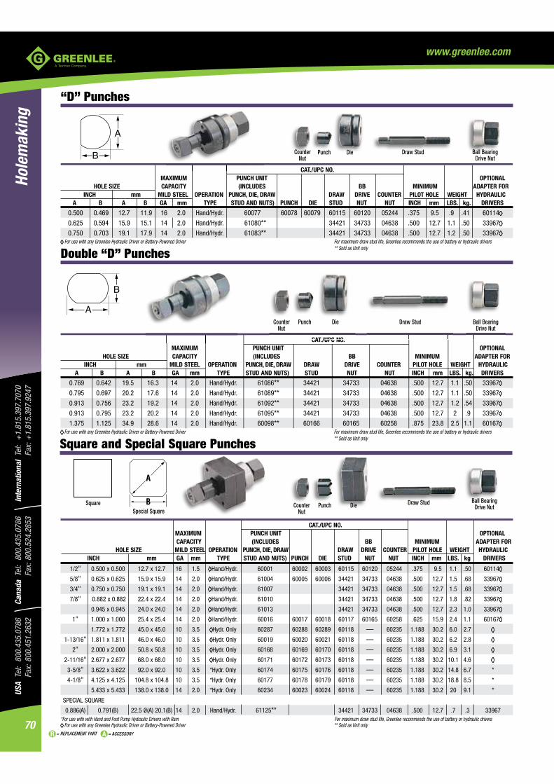
USA
Tel:
800
.435
.078
6
Fax:
800
.451
.263
2Ca
nada
Tel
: 80
0.43
5.07
86
Fax:
800
.524
.285
3In
tern
atio
nal
Tel:
+1.
815.
397.
7070
Fa
x: +
1.81
5.39
7.92
47
70
Hole
mak
ing
= REPLACEMENT PART = ACCESSORY
www.greenlee.com
“D” Punches
Draw Stud
CAT./UPC NO. MAXIMUM PUNCH UNIT OPTIONAL HOLE SIZE CAPACITY (INCLUDES BB MINIMUM ADAPTER FOR INCH mm MILD STEEL OPERATION PUNCH, DIE, DRAW DRAW DRIVE COUNTER PILOT HOLE WEIGHT HYDRAULIC A B A B GA mm TYPE STUD AND NUTS) STUD NUT NUT INCH mm LBS. kg. DRIVERS
0.769 0.642 19.5 16.3 14 2.0 Hand/Hydr. 61086** 34421 34733 04638 .500 12.7 1.1 .50 33967
0.795 0.697 20.2 17.6 14 2.0 Hand/Hydr. 61089** 34421 34733 04638 .500 12.7 1.1 .50 33967
0.913 0.756 23.2 19.2 14 2.0 Hand/Hydr. 61092** 34421 34733 04638 .500 12.7 1.2 .54 33967
0.913 0.795 23.2 20.2 14 2.0 Hand/Hydr. 61095** 34421 34733 04638 .500 12.7 2 .9 33967
1.375 1.125 34.9 28.6 14 2.0 Hand/Hydr. 60098** 60166 60165 60258 .875 23.8 2.5 1.1 60167 For use with any Greenlee Hydraulic Driver or Battery-Powered Driver For maximum draw stud life, Greenlee recommends the use of battery or hydraulic drivers
** Sold as Unit only
CAT /UPC NO
Draw StudCounter Nut
Punch Die Ball Bearing Drive Nut
SquareSpecial Square
Counter Nut
Punch Die Draw Stud Ball Bearing Drive Nut
CAT./UPC NO. MAXIMUM PUNCH UNIT OPTIONAL CAPACITY (INCLUDES BB MINIMUM ADAPTER FOR
HOLE SIZE MILD STEEL OPERATION PUNCH, DIE, DRAW DRAW DRIVE COUNTER PILOT HOLE WEIGHT HYDRAULIC INCH mm GA mm TYPE STUD AND NUTS) PUNCH DIE STUD NUT NUT INCH mm LBS. kg DRIVERS
1/2" 0.500 x 0.500 12.7 x 12.7 16 1.5 Hand/Hydr. 60001 60002 60003 60115 60120 05244 .375 9.5 1.1 .50 60114
5/8" 0.625 x 0.625 15.9 x 15.9 14 2.0 Hand/Hydr. 61004 60005 60006 34421 34733 04638 .500 12.7 1.5 .68 33967
3/4" 0.750 x 0.750 19.1 x 19.1 14 2.0 Hand/Hydr. 61007 34421 34733 04638 .500 12.7 1.5 .68 33967
7/8" 0.882 x 0.882 22.4 x 22.4 14 2.0 Hand/Hydr. 61010 34421 34733 04638 .500 12.7 1.8 .82 33967
0.945 x 0.945 24.0 x 24.0 14 2.0 Hand/Hydr. 61013 34421 34733 04638 .500 12.7 2.3 1.0 33967
1" 1.000 x 1.000 25.4 x 25.4 14 2.0 Hand/Hydr. 60016 60017 60018 60117 60165 60258 .625 15.9 2.4 1.1 60167
1.772 x 1.772 45.0 x 45.0 10 3.5 Hydr. Only 60287 60288 60289 60118 — 60235 1.188 30.2 6.0 2.7
1-13/16" 1.811 x 1.811 46.0 x 46.0 10 3.5 Hydr. Only 60019 60020 60021 60118 — 60235 1.188 30.2 6.2 2.8
2" 2.000 x 2.000 50.8 x 50.8 10 3.5 Hydr. Only 60168 60169 60170 60118 — 60235 1.188 30.2 6.9 3.1
2-11/16" 2.677 x 2.677 68.0 x 68.0 10 3.5 Hydr. Only 60171 60172 60173 60118 — 60235 1.188 30.2 10.1 4.6
3-5/8" 3.622 x 3.622 92.0 x 92.0 10 3.5 *Hydr. Only 60174 60175 60176 60118 — 60235 1.188 30.2 14.8 6.7 *
4-1/8" 4.125 x 4.125 104.8 x 104.8 10 3.5 *Hydr. Only 60177 60178 60179 60118 — 60235 1.188 30.2 18.8 8.5 *
5.433 x 5.433 138.0 x 138.0 14 2.0 *Hydr. Only 60234 60023 60024 60118 — 60235 1.188 30.2 20 9.1 *
SPECIAL SQUARE
0.886(A) 0.791(B) 22.5 Ø(A) 20.1(B) 14 2.0 Hand/Hydr. 61125** 34421 34733 04638 .500 12.7 .7 .3 33967*For use with with Hand and Foot Pump Hydraulic Drivers with Ram For maximum draw stud life, Greenlee recommends the use of battery or hydraulic drivers
For use with any Greenlee Hydraulic Driver or Battery-Powered Driver ** Sold as Unit only
Counter Nut
Punch Die
CAT./UPC NO. MAXIMUM PUNCH UNIT OPTIONAL HOLE SIZE CAPACITY (INCLUDES BB MINIMUM ADAPTER FOR INCH mm MILD STEEL OPERATION PUNCH, DIE, DRAW DRAW DRIVE COUNTER PILOT HOLE WEIGHT HYDRAULIC A B A B GA mm TYPE STUD AND NUTS) PUNCH DIE STUD NUT NUT INCH mm LBS. kg. DRIVERS
0.500 0.469 12.7 11.9 16 2.0 Hand/Hydr. 60077 60078 60079 60115 60120 05244 .375 9.5 .9 .41 60114
0.625 0.594 15.9 15.1 14 2.0 Hand/Hydr. 61080** 34421 34733 04638 .500 12.7 1.1 .50 33967
0.750 0.703 19.1 17.9 14 2.0 Hand/Hydr. 61083** 34421 34733 04638 .500 12.7 1.2 .50 33967 For use with any Greenlee Hydraulic Driver or Battery-Powered Driver For maximum draw stud life, Greenlee recommends the use of battery or hydraulic drivers
** Sold as Unit only
Draw Stud Ball Bearing Drive Nut
Double “D” Punches
Square and Special Square Punches

71
USA Tel: 800.435.0786
Fax: 800.451.2632Canada Tel: 800.435.0786
Fax: 800.524.2853International Tel: +
1.815.397.7070
Fax: +1.815.397.9247
Holemaking
= REPLACEMENT PART = ACCESSORY
www.greenlee.com
Counter Nut
Punch Die
CAT./UPC NO. MAXIMUM PUNCH UNIT OPTIONAL HOLE SIZE CAPACITY (INCLUDES BB MINIMUM ADAPTER FOR MILD STEEL OPERATION PUNCH, DIE, DRAW DRAW DRIVE COUNTER PILOT HOLE Ø WEIGHT HYDRAULIC INCH mm GA mm TYPE STUDS AND NUTS) PUNCH DIE STUD NUT NUT INCH mm LBS. kg DRIVERS
0.437 x 0.875 11.1 x 22.2 16 1.5 Hand/Hydr. 60025 60026 60027 60115 60120 05244 .375 9.5 1.2 .5 60114
0.670 x 0.749 17.0 x 19.0 14 2.0 Hand/Hydr. 61028 60029 60030 34421 34733 04638 .500 12.7 1.5 .68 33967
0.750 x 1.140 19.1 x 29.0 14 2.0 Hand/Hydr. 60031 60032 60033 60117 60165 60258 .625 15.9 2.3 1.0 60167
0.750 x 1.310 19.1 x 33.3 14 2.0 Hand/Hydr. 60034 60035 60036 60117 60165 60258 .625 15.9 2.3 1.0 60167
0.861 x 1.018 21.9 x 25.9 14 2.0 Hand/Hydr. 60037 60038 60039 60117 60165 60258 .625 15.9 2.3 1.0 60167
0.866 x 1.181 22.0 x 30.0 14 2.0 Hand/Hydr. 60040 60041 60042 60117 60165 60258 .625 15.9 2.4 1.1 60167
0.866 x 1.654 22.0 x 42.0 14 2.0 Hand/Hydr. 60043 60045 60046 60117 60165 60258 .625 15.9 2.9 1.3 60167
0.990 x 1.140 25.1 x 29.0 14 2.0 Hand/Hydr. 60047 60048 60049 60117 60165 60258 .625 15.9 2.6 1.2 60167
1.250 x 1.380 31.8 x 35.1 14 2.0 Hand/Hydr. 60050 60051 60052 60117 60165 60258 .625 15.9 3.1 1.4 60167
1.312 x 2.625 33.3 x 67.9 10 3.5 Hydr. Only 60053 60054 60055 60118 — 60235 1.188 30.2 5.1 2.3
1.378 x 2.047 35.0 x 52.0 10 3.5 Hydr. Only 60056 60057 60058 60118 — 60235 1.188 30.2 6.1 2.8
1.378 x 2.559 35.0 x 65.0 10 3.5 Hydr. Only 60059 60060 60061 60118 — 60235 1.188 30.2 6.8 3.1
1.378 x 3.228 35.0 x 82.0 14 2.0 *Hydr. Only 60062 60063 60064 60118 — 60235 1.188 30.2 7.7 3.5 *
1.378 x 4.409 35.0 x 112.0 14 2.0 *Hydr. Only 60065 60066 60067 60118 — 60235 1.188 30.2 9.2 4.2 *
1.811 x 3.622 46.0 x 92.0 10 3.5 *Hydr. Only 60068 60069 60070 60118 — 60235 1.188 30.2 8.9 4.0 *
2.250 x 3.500 57.2 x 88.9 10 3.5 *Hydr. Only 60071 60072 60073 60118 — 60235 1.188 30.2 10.1 4.6 *
2.677 x 5.433 68.0 x 138.0 14 2.0 *Hydr. Only 60074 60075 60076 60118 — 60235 1.188 30.2 16.1 7.3 *
*For use with with Hand and Foot Pump Hydraulic Drivers with Ram For maximum draw stud life, Greenlee recommends the use of battery or hydraulic drivers For use with any Greenlee Hydraulic Driver or Battery-Powered Driver
Draw Stud Ball Bearing Drive Nut
PUNCH UNIT DIMENSIONS REPLACEMENT CAT./UPC NO. WEIGHT NO. OF SQUARE CAT. NO. UPC NO. PINS A B C PUNCH DIE UNIT DRAW STUD COUNTER NUT DRIVE NUT LBS. kg.
229 34436 9 .787" .982" .469" 34441 35196 34421 04638 34733 1.4 .64 (20.0 mm) (24.9 mm) (11.9 mm)
231 34437 15 1.127" 1.309" .469" 34442 35197 34421 04638 34733 1.5 .68 (28.6 mm) (33.3 mm) (11.9 mm)
RS232 34420 25 1.655" 1.853" .469" 34418 35198 34421 04638 34733 2.0 .91 (42.0 mm) (47.1 mm) (11.9 mm)
234 34429 37 2.296" 2.497" .469" 34427 35199 34421 04638 34733 2.0 .91 (58.3 mm) (63.4 mm) (11.9 mm)
238 34444 50 2.201" 2.402" .579" 34443 35200 34421 04638 34733 2.0 .91 (55.9 mm) (61.0 mm) (14.7 mm)
For maximum draw stud life, Greenlee recommends the use of battery or hydraulic drivers
Electronic Connector Panel Punches
® step bits.)
Cannon-type or equivalent connectors in 9, 15, 25, 37 or 50-pin configurations.
SPECIFICATIONS
Capacity gauge (3.5 mm) aluminumOperation ® and Quick Draw 90® hydraulic
drivers, Battery Driver, Ram and Pump hydraulic drivers aluminum
Rectangular Punches
Rectangle

USA
Tel:
800
.435
.078
6
Fax:
800
.451
.263
2Ca
nada
Tel
: 80
0.43
5.07
86
Fax:
800
.524
.285
3In
tern
atio
nal
Tel:
+1.
815.
397.
7070
Fa
x: +
1.81
5.39
7.92
47
72
Hole
mak
ing
= REPLACEMENT PART = ACCESSORY
www.greenlee.com
Replacement Draw Studs for Manual Drivers
304AVBB – 3/4" (19.0 mm) x 2-15/16" (75 mm)
00042 – 3/8" (9.5 mm) x 1-5/8" (41 mm)
249AVBB – 3/4" (19.0 mm) x 2-1/8" (54 mm)
3026AV – 1-1/8" (28.6 mm) x 7-1/2" (190 mm)
1434AV 3/4" (19.0 mm) x 5-1/2" (140 mm)
1675AV Draw Stud – 1/4" (6.4 mm) x 1-3/8" (35 mm)
Replacement Draw Stud Selection GuideRefer to the ACTUAL SIZE PICTURES and information below when ordering a replacement draw stud. Sizes given are diameter X length.
DRAW STUDS FOR KNOCKOUTS

73
USA Tel: 800.435.0786
Fax: 800.451.2632Canada Tel: 800.435.0786
Fax: 800.524.2853International Tel: +
1.815.397.7070
Fax: +1.815.397.9247
Holemaking
= REPLACEMENT PART = ACCESSORY
www.greenlee.com
Replacement Draw Studs for Hydraulic Drivers
29452 – 3/4" (19.0 mm) x 5-1/2" (140 mm)
1557AA– 1-1/8" (28.6 mm) x 3" (76 mm)
2113AA – 3/4" (19.0 mm) x 5-3/8" (137 mm)
29451 – 7/16" (11.1 mm) x 4-1/4" (108 mm)
1614SS– 3/8" (9.5 mm) x 2-13/16" (71 mm)
33967 (Adapter) – 3/4" (19 mm) x 3/8" (9.5 mm) internal
Replacement Draw Stud Selection GuideRefer to the ACTUAL SIZE PICTURES and information below when ordering a replacement draw stud. Sizes given are diameter X length.
60114 (Adapter) – 3/4" (19 mm) x 1/4" (6.35 mm) internal
31872 – 3/4" (19 mm) x 4-1/2" (114.3 mm)
60167 (Adapter) – 3/4" (19 mm) x 1/2" (12.7 mm) internal

USA
Tel:
800
.435
.078
6
Fax:
800
.451
.263
2Ca
nada
Tel
: 80
0.43
5.07
86
Fax:
800
.524
.285
3In
tern
atio
nal
Tel:
+1.
815.
397.
7070
Fa
x: +
1.81
5.39
7.92
47
74
Hole
mak
ing
= REPLACEMENT PART = ACCESSORY
www.greenlee.com
Replacement Draw Studs for Ratchet Drivers
12099 – 3/4" (19.0 mm) x 4-3/4" (121 mm)
12097 – 3/8" (9.5 mm) x 3-1/2" (89 mm)
30227 – 7/16" (11.1 mm) x 3-5/8" (92 mm)
Replacement Draw Stud Selection GuideRefer to the ACTUAL SIZE PICTURES and information below when ordering a replacement draw stud. Sizes given are diameter X length.

75
USA Tel: 800.435.0786
Fax: 800.451.2632Canada Tel: 800.435.0786
Fax: 800.524.2853International Tel: +
1.815.397.7070
Fax: +1.815.397.9247
Holemaking
= REPLACEMENT PART = ACCESSORY
www.greenlee.com
Replacement Draw Studs for Special Shape Punches
60166 – 1/2" (12.7 mm) x 4-5/8" (117.5 mm)
60117 – 1/2" (12.7 mm) x 4-5/8" (117.5 mm)
34421 – 3/8" (9.5 mm) x 3-1/2" (88.9 mm)
60115 – 1/4" (6.3 mm) x 3-7/16" (87.3 mm)
60118 – 3/4" (19 mm) x 6-3/4" (171.5 mm)
Replacement Draw Stud Selection GuideRefer to the ACTUAL SIZE PICTURES and information below when orderinga replacement draw stud. Sizes given are diameter X length.
For maximum draw stud life, Greenlee recommends the use of battery or hydraulic drivers.
60116 – 1/2" (12.7 mm) x 4-5/8" (117.5 mm)

USA
Tel:
800
.435
.078
6
Fax:
800
.451
.263
2Ca
nada
Tel
: 80
0.43
5.07
86
Fax:
800
.524
.285
3In
tern
atio
nal
Tel:
+1.
815.
397.
7070
Fa
x: +
1.81
5.39
7.92
47
76
Hole
mak
ing
= REPLACEMENT PART = ACCESSORY
www.greenlee.com
PLUMBER STUD PUNCH
ACTUAL HOLE SIZE WEIGHT LENGTH HEIGHT CAPACITY
CAT. NO. UPC NO. IN. mm LBS. kg IN. mm IN. mm GA mm
713 06430 2-5/8 66.7 10.6 4.8 23-1/2 596 9-3/4 247 24-20 0.9
STUD PUNCHESStructural Stud Punch
5 seconds.200 holes per battery charge, 2 batteries & charger included,
eliminating downtime.
For use with Greenlee 712A bushings.
Plumber Stud Punch
professional-looking installation of 2" water, vent, waste pipes.
metal studs.
tool for easy handling–10.6 lb. (4.8 kg).
BATTERY-POWERED STUD PUNCH
ACTUAL HOLE SIZE WEIGHT LENGTH HEIGHT CAPACITY
CAT. NO. UPC NO. IN. mm LBS. kg IN. mm IN. mm GA mm BATTERY CHARGER
ESP710-11 10307 1-11/32 34.1 9.2 4.2 15 381 11-3/4 298 16 1.5 12V2.0 Ah NiCd 120 Volt
ESP710-12 10308 1-11/32 34.1 9.2 4.2 15 381 11-3/4 298 16 1.5 12V2.0 Ah NiCd 12 Volt
ESP710-22 10309 1-11/32 34.1 9.2 4.2 15 381 11-3/4 298 16 1.5 12V2.0 Ah NiCd 230 Volt
TERY-YY POWERED STUD PUNCH
CAT. NO. UPC NO. DESCRIPTION
12274 12274 Carrying Strap07063 07063 12V NIMH batteryMKESP710GL 10303 Carrying Case03046 03046 120V Charger
CAT. NO. UPC NO. DESCRIPTION
03048 03048 12V Charger03047 03047 230V ChargerHE.9055 10344 Replacement Punch21297 21297 Replacement Die
CAT. NO. UPC NO. DESCRIPTION
08377 08377 Punch for 71308379 08379 Die for 713

77
USA Tel: 800.435.0786
Fax: 800.451.2632Canada Tel: 800.435.0786
Fax: 800.524.2853International Tel: +
1.815.397.7070
Fax: +1.815.397.9247
Holemaking
= REPLACEMENT PART = ACCESSORY
www.greenlee.com
WEIGHT CAT. NO. UPC NO. DESCRIPTION LBS. kg
709 22280 7/8" (22.2 mm) Diameter Stud Punch 7 3.2
710 21285 1-11/32" (34.1 mm) Diameter Stud Punch 7.5 3.5
30968 30968 Conversion Kit – Upgrades Early Model 709 or 710 from 24 to 20 Gauge Maximum Capacity
121AV 04006 Punch for 709
22286 22286 Die for 709
24823 24823 Punch for 710
21297 21297 Die for 710
06015 06015 Repair Kit
36617 36617 Link
Metal Stud Punches
reducing operator fatigue.
it possible to punch in tight places.
gauge maximum capacity.
SPECIFICATIONS
Capacity 709 - 1-5/8" (41.3 mm) and wider studs. 20 gauge (0.9 mm) steel studs. 710 - 2-1/2" (63.4 mm) and wider studs. 20 gauge (0.9 mm) steel studs.
¨
WEIGHT CAT. NO. UPC NO. DESCRIPTION LBS. kg
711C 22288 100 Bushings for Hole Punched by 709 for .5 .23 7/8" (22.2 mm) Diameter Hole 711M 22289 1,000 Bushings for Hole Punched by 709 for 3.7 1.7 7/8" (22.2 mm) Diameter Hole 712A100 05927 100 Bushings for Pre-Punched Hole or 1-11/32" 1.4 .64 (34.1 mm) Diameter Hole Punched by 710 712A1000 05928 1,000 Bushings for Pre-Punched Hole or 15.5 7.0 1-11/32" (34.1 mm) Diameter Hole Punched by 710
Bushings for Metal Stud Punches
to 2.5 mm).
on raw metal edges.
SPECIFICATIONS
MANUAL STUD PUNCH
ACTUAL HOLE SIZE WEIGHT LENGTH HEIGHT CAPACITY
CAT. NO. UPC NO. IN. mm LBS. kg IN. mm IN. mm GA mm
724 10415 1-1/4 31.7 4.0 1.8 16-3/4 426 4-1/2 114 24-20 0.9
Manual Stud Punch
possible to punch in tight places.
MANUAL STUD PUNCH
ACTUAL HOLE
CAT. NO. UPC NO. DESCRIPTION
10419 10419 Punch for 724

USA
Tel:
800
.435
.078
6
Fax:
800
.451
.263
2Ca
nada
Tel
: 80
0.43
5.07
86
Fax:
800
.524
.285
3In
tern
atio
nal
Tel:
+1.
815.
397.
7070
Fa
x: +
1.81
5.39
7.92
47
78
Hole
mak
ing
= REPLACEMENT PART = ACCESSORY
www.greenlee.com
Combination Drill/Tap Bits
DRILL/TAPS
operation with power drill saves labor and time.
SPECIFICATIONS
Material thickness Up to 10 gaugeMaterial type Mild steel, copper, brass, aluminum
Shank 1/4" quick change hexDrill Material High-speed steelDrill point Split point with web thinning
NOTE: TO EXTEND THE LIFE OF YOUR TOOL, SEE CUTTING/THREADING OIL ON PAGE 388.
CAT. NO. UPC NO. DESCRIPTION DTAPKIT DTAPKITM
DTAPKITM 12151 M3-M10 6 Piece Drill/Tap SetDTAPKIT 17620 6-32 to 1/4-20 6-piece Drill
Tap Set
DTAP6-32 17611 6-32NC Drill/Tap Bit XDTAP8-32 17612 8-32NC Drill/Tap Bit XDTAP10-24 17613 10-24NC Drill/Tap Bit X DTAP10-32 17614 10-32NF Drill/Tap Bit XDTAP12-24 17615 12-24NC Drill/Tap Bit XDTAP1/4-20 17616 1/4-20NC Drill/Tap Bit XDTAP5/16-18 11627 5/16-18NC Drill/Tap BitDTAP3/8-16 11628 3/8-16NC Drill/Tap Bit DTAPM3C 12160 M3 X .50 Drill/Tap Bit XDTAPM4C 12161 M4 X .70 Drill/Tap Bit XDTAPM5C 12162 M5 X .80 Drill/Tap Bit XDTAPM6C 12163 M6 X 1.00 Drill/Tap Bit XDTAPM8C 12164 M8 X 1.25 Drill/Tap Bit XDTAPM10C 12165 M10 X 1.50 Drill/Tap Bit X
DTAPKITM

79
USA Tel: 800.435.0786
Fax: 800.451.2632Canada Tel: 800.435.0786
Fax: 800.524.2853International Tel: +
1.815.397.7070
Fax: +1.815.397.9247
Holemaking
= REPLACEMENT PART = ACCESSORY
www.greenlee.com
CAT. NO. UPC NO. DESCRIPTION 03607 35884 34401 34403 30008 35936
03607
35884
SIZE CAT./UPC NO. INCHES mm 34410 34401 36402 30005 34411 34403 30008 36414 36018 36020 36022 1/8 3.2 5/32" 4.0 3/16" 4.8 7/32" 5.6 1/4" 6.4 9/32" 7.1 5/16" 7.9 11/32" 8.7 3/8" 9.5 0.382" 9.7 13/32" 10.3 7/16" 11.1 15/32" 11.9 0.492" 12.5 Pg-7 1/2" 12.7 9/16" 14.3 0.598" 15.2 Pg-9 5/8" 15.9 0.638" 16.2 ISO-16 11/16" 17.5 0.732" 18.6 Pg-11 3/4" 19.1 0.803" 20.4 Pg-13 ISO-20 13/16" 20.6 7/8" 22.2 0.886" 22.5 Pg-16 1.00" 25.4 ISO-25 1.114" 28.3 Pg-21 1-1/8" 28.6 1.201" 30.5 1-7/32" 31.0 1-1/4" 31.8 1.280" 32.5 ISO-32 1-3/8" 34.9 Overall Length 1-7/8" 3-3/8" 3-7/16" 3-7/16" 2-7/16" 3-9/16" 2-15/16" 3-1/8" 1-7/8" 3-3/4" 3-3/8" (47.6 mm) (85.7 mm) (87.3 mm) (87.3 mm) (61.9 mm) (90.5 mm) (74.6 mm) (79.4 mm) (47.6 mm) (95.3 mm) (85.7 mm)
Minimum 3/8" 3/8" 3/8" 3/8" 3/8" 3/8" 3/8" 3/8" 3/8" 3/8" 3/8" Chuck Size (9.5 mm) (9.5 mm) 9.5 mm) (9.5 mm) (9.5 mm) (9.5 mm) (9.5 mm) (9.5 mm) (9.5 mm) (9.5 mm) (9.5 mm) Maximum Material 10 gauge 10 gauge 3/8" 10 gauge 10 gauge 10 gauge 10 gauge 10 gauge 10 gauge 1/4" 1/4" Thickness (3.5 mm) (3.5 mm) (9.5 mm) (3.5 mm) (3.5 mm) (3.5 mm) (3.5 mm) (3.5 mm) (3.5 mm) (6.4 mm) (6.4 mm)
Bit Extension 901 901 901 901 — — — — 901 — —
METRIC
1/2" 1/2" 1/2" 13/16" 7/8" 7/8" 1-1/8" 1-3/8" 9.7 mm 30.5 mm 32.5 mm (12.7 mm) (12.7 mm) (12.7 mm) (20.6 mm) (22.2 mm) (22.2 mm) Electrician’s (34.9 mm) (.382") (1.201") (1.280") Single-Hole Multi-Hole Multi-Hole Multi-Hole Single-Hole Multi-Hole Step Bit Multi-Hole Multi-Hole Multi-Hole Step Bit Step Bit Step Bit Step Bit Step Bit Step Bit Step Bit Step Bit Step Bit
Single-hole bits are designed to drill one indicated hole size through a series of steps from bit tip to full size.
Multi-hole bits allow you to drill a hole in any of the stated diameters.
STEP BITSKwik Stepper® Step Bits
SPECIFICATIONS
Hole Sizes From 1/8" through 1-3/8" (3.2 - 34.9 mm)Capacity Cut up through 3/8" (9.5 mm) mild steel, copper, brass,
aluminum, wood, plastic and laminates
CAT. NO. UPC NO. DESCRIPTION
35884 35884 Kwik Stepper® Step Bit Kit03607 03607 Kwik Stepper® Step Bit Kit
03607
IFICATIONS
Sizes From 1/8" through 1-3/8" (3.2 - 34.9 mm)
3588

USA
Tel:
800
.435
.078
6
Fax:
800
.451
.263
2Ca
nada
Tel
: 80
0.43
5.07
86
Fax:
800
.524
.285
3In
tern
atio
nal
Tel:
+1.
815.
397.
7070
Fa
x: +
1.81
5.39
7.92
47
80
Hole
mak
ing
= REPLACEMENT PART = ACCESSORY
www.greenlee.com
61PTS SHORTY, 62PTS AND 61/62 PTS BIG SHANK SHORTY NAIL EATER II® BITS POP BULK HOLE DIA. HEX SHANK WEIGHT CAT. NO. UPC NO. UPC NO. INCH mm INCH mm LBS. g
61PTS–5/8 30419 — 5/8 15.9 5/16 7.9 .3 137
61PTS–3/4 30423 — 3/4 19.1 5/16 7.9 .4 182
61PTS–7/8 30427 — 7/8 22.2 5/16 7.9 .5 227
61PTS–1 30429 — 1 25.4 5/16 7.9 .8 363
62PTS–5/8 31788 — 5/8 15.9 7/16 11.1 .3 137
62PTS–11/16 31790 — 11/16 17.5 7/16 11.1 .4 182
62PTS–3/4 31792 36640 3/4 19.1 7/16 11.1 .5 227
62PTS–13/16 31794 — 13/16 20.6 7/16 11.1 .5 227
62PTS–7/8 31796 36642 7/8 22.2 7/16 11.1 .6 273
62PTS–1 31798 36643 1 25.4 7/16 11.1 .7 318
61/62PTS–1-1/8 30431 — 1-1/8 28.6 7/16 11.1 .9 409
61/62PTS–1-1/4 30433 — 1-1/4 31.8 7/16 11.1 1.1 499
66PT NAIL EATER II® BITS POP BULK HOLE DIA. HEX SHANK WEIGHT CAT. NO. UPC NO. UPC NO. INCH mm INCH mm LBS. g
66PT–1/2 30915 — 1/2 12.7 5/16 7.9 .7 318
66PT–5/8 30919 — 5/8 15.9 7/16 11.1 .8 363
66PT–11/16 30921 — 11/16 17.5 7/16 11.1 1 454
66PT–3/4 30923 36659 3/4 19.1 7/16 11.1 1.2 545
66PT–13/16 30925 — 13/16 20.6 7/16 11.1 1.2 545
66PT–7/8 30927 36662 7/8 22.2 7/16 11.1 1.5 681
66PT–15/16 30929 — 15/16 23.8 7/16 11.1 1.6 726
66PT–1 30931 36664 1 25.4 7/16 11.1 1.8 817
66PT–1-1/8 30935 — 1-1/8 28.6 7/16 11.1 2.3 1044
66PT–1-1/4 30937 — 1-1/4 31.8 7/16 11.1 2.8 1270
HARDWARE HOLE OVERALL HEX DIA. DIA. LENGTH SHANK WEIGHT CAT. NO. UPC NO. INCH mm INCH mm INCH mm INCH mm LBS. g
37868 37868 9/16 14.3 5/8 15.9 18 457.2 7/16 11.1 0.9 409
37869 37869 11/16 17.5 3/4 19.1 18 457.2 7/16 11.1 1.1 499
37870 37870 13/16 20.6 7/8 22.2 18 457.2 7/16 11.1 1.4 636
37871 37871 15/16 23.8 1 25.4 18 457.2 7/16 11.1 1.5 681
reduced cutting loads.
and provides longer life.
through three abutting 2 x 4s.
SPECIFICATIONS 61 PTS SHORTY NAIL EATER II®, 62 PTS AND 61/62 BIG SHANK SHORTY NAIL EATER II BITS
Overall Length 7-5/8" (193.7 mm) Twist Length 5" (127 mm) Electric drill required 61 PTS – 5/8 through 61 PTS - 1, minimum
66 PT NAIL EATER II® BITS Overall Length 18" (457.2 mm) Twist Length 15" (381 mm)
Nail Eater II® Wood Boring Bits
Nail Eater II® Impact Bits
AUGER BITS

81
USA Tel: 800.435.0786
Fax: 800.451.2632Canada Tel: 800.435.0786
Fax: 800.524.2853International Tel: +
1.815.397.7070
Fax: +1.815.397.9247
Holemaking
= REPLACEMENT PART = ACCESSORY
www.greenlee.com
LENGTH HEX SHANK HOLE DIA. HEAD DIA. WEIGHT CAT. NO. UPC NO. INCH mm INCH mm INCH mm INCH mm LBS. g
901-12 02706 12 304.8 1/4 6.4 1/4 6.4 9/16 14.3 1.4 636 902-18 02707 18 457.2 5/16 7.9 23/64 9.1 21/32 16.7 2.5 1134 902-24 02708 24 609.6 5/16 7.9 23/64 9.1 21/32 16.7 3.4 1543 904-5-1/2 34996 5-1/2 139.7 7/16 11.1 1/2 12.7 1 25.4 2.1 953 904H-12 34980 12 304.8 7/16 11.1 ** 23/32 18.3 2.9 1316 904H-18 35356 18 457.2 7/16 11.1 ** 23/32 18.3 4.3 1951 904H-24 35358 24 609.6 7/16 11.1 ** 23/32 18.3 5 2268
**For 7/16" Hex or 1/2" Round with 3 Flats, 1/4" Wide
CAT. NO. UPC NO. DESCRIPTION
3713GB 50962 Set Screw for 901-12/027063678GB 50753 Set Screw for 902-18/02707 and 902-24/027083693GB 50765 Set Screw for 904-5-1/2/3499653892 53892 Set Screw for 904H-12/34980, 904H-18/35356
and 904H-24/3535851376 51376
902-18/02707 and 902-24/0270852144 52144
Bit Extensions
CAT. NO. UPC NO. DESCRIPTION
3713GB 50962 Set Screw for 901-12/027063678GB 50753 Set Screw for 902-18/02707 a3693GB 50765 Set Screw for 904-5-1/2/349953892 53892 Set Screw for 904H-12/34980
® bits, Electrician's bits and Step bits.

USA
Tel:
800
.435
.078
6
Fax:
800
.451
.263
2Ca
nada
Tel
: 80
0.43
5.07
86
Fax:
800
.524
.285
3In
tern
atio
nal
Tel:
+1.
815.
397.
7070
Fa
x: +
1.81
5.39
7.92
47
82
Hole
mak
ing
= REPLACEMENT PART = ACCESSORY
www.greenlee.com
UPC HOLE DIA. OVERALL LENGTH PIPE & WEIGHT CAT. NO. NO. INCH mm INCH mm CONDUIT SIZE LBS. g
149H–1 12630 1 25.4 5 127.0 1/2" .4 18
149H–1-1/8 12631 1-1/8 28.6 5 127.0 1/2" & 3/4" .3 137
149H–1-1/4 12632 1-1/4 31.8 5 127.0 3/4" .3 137
149H–1-3/8 12633 1-3/8 34.9 5 127.0 — .4 182
149H–1-1/2 12634 1-1/2 38.1 5 127.0 1" .4 182
149H–1-3/4 12635 1-3/4 44.4 5 127.0 1-1/4" .5 227
149H–2 12636 2 50.8 5 127.0 — .6 273
149H–2-1/8 12637 2-1/8 54.0 5 127.0 1-1/2" .7 318
149H–2-1/4 12638 2-1/4 57.2 5 127.0 — .7 318
149H–2-9/16 12639 2-9/16 65.1 5 127.0 2" .8 363
149H–3 12640 3 76.2 5 127.0 2-1/2" 1.1 499
149H–3-5/8 12641 3-5/8 92.1 6-1/4 158.8 3" 2.1 953
149H–4-5/8 12642 4-5/8 117.5 6-1/4 158.8 4" 2.6 1179
149HContractor’s Bit Kit
WEIGHT CAT. NO. UPC NO. DESCRIPTION LBS. kg
149H 34995 Contractor’s Bit Kit 6 2.72
KIT CAT./UPC NO. CAT. NO. UPC NO. DESCRIPTION 1441/34995
149H–1 12630 1" (25.4 mm) E-Z Bore Bit
149H–1-1/8 12631 1-1/8" (28.6 mm) E-Z Bore Bit
149H–1-1/4 12632 1-1/4" (31.8 mm) E-Z Bore Bit
149H–1-1/2 12634 1-1/2" (38.1 mm) E-Z Bore Bit
149H–1-3/4 12635 1-3/4" (44.4 mm) E-Z Bore Bit
149H–2-1/8 12637 2-1/8" (54.0 mm) E-Z Bore Bit
149H–2-9/16 12639 2-9/16" (65.0 mm) E-Z Bore Bit
4236AV 05133 Double End Screw Point
51376
52144
904–5-1/2 34996 5-1/2" Bit Extension
34997 34997 Plastic Case
E-Z Bore® Bits
Conduit and Pipe Bit Sets
material you are drilling. Fine thread for hardwoods, coarse thread for fast, effortless drilling even in soft, gummy woods.
stationary boring machines.
CAT. NO. UPC NO. DESCRIPTION
4236AV 05133 Screw Point for 149G - 1, 149G - 1-1/8, 149G - 1-1/4, 149G - 1-3/8, 149G - 1-1/2, 149G - 1-3/4, 149G - 2, 149G - 2-1/8, 149G - 2-1/4, 149G - 2-9/16 and 149G - 3
18358 18358 Screw Point for 149G-3-5/8 and 4-5/8
® bits.
149HContractor’s Bit Kit

83
USA Tel: 800.435.0786
Fax: 800.451.2632Canada Tel: 800.435.0786
Fax: 800.524.2853International Tel: +
1.815.397.7070
Fax: +1.815.397.9247
Holemaking
= REPLACEMENT PART = ACCESSORY
www.greenlee.com
33A SPADE BITS – LENGTH 6-1/4" (158.8 mm)
KIT CAT./UPC NO. HOLE DIA. HEX SHANK WEIGHT 33AR-6/ CAT. NO. UPC NO. INCH mm INCH mm LBS. g 20364 33A–1/4 20344 1/4 6.4 1/4 6.4 .05 23.0 33A–3/8 20346 3/8 9.5 1/4 6.4 .09 40.8 1 33A–1/2 20348 1/2 12.7 1/4 6.4 .1 45.3 1 33A–5/8 20350 5/8 15.9 1/4 6.4 .1 45.3 1 33A–3/4 20352 3/4 19.1 1/4 6.4 .1 45.3 1 33A–7/8 20354 7/8 22.2 1/4 6.4 .12 54.4 1 33A–1 20357 1 25.4 1/4 6.4 .12 54.4 1 33A–1-1/8 20358 1-1/8 28.6 1/4 6.4 .15 68.0 33A–1-1/4 20359 1-1/4 31.8 1/4 6.4 .15 68.0 33A–1-3/8 20360 1-3/8 34.9 1/4 6.4 .16 72.6 33A–1-1/2 20361 1-1/2 38.1 1/4 6.4 .16 72.6
33L SPADE BITS – LENGTH 16" (406.4 mm) HOLE DIA. HEX SHANK WEIGHT CAT. NO. UPC NO. INCH mm INCH mm LBS. g 33L–1/4 31535 1/4 6.4 1/4 6.4 .22 9933L–3/8 31536 3/8 9.5 1/4 6.4 .32 145
33L–1/2 31537 1/2 12.7 1/4 6.4 .33 150 33L–5/8 31539 5/8 15.9 1/4 6.4 .4 181 33L–3/4 31540 3/4 19.1 1/4 6.4 .4 181 33L–7/8 31541 7/8 22.2 1/4 6.4 .55 250 33L–1 31542 1 25.4 1/4 6.4 .33 150 33L–1-1/8 31543 1-1/8 28.6 1/4 6.4 .58 263 33L–1-1/4 31544 1-1/4 31.8 1/4 6.4 .56 254 33L–1-1/2 31545 1-1/2 38.1 1/4 6.4 .6 272
SPADE BIT KITS WEIGHT
CAT. NO. UPC NO. DESCRIPTION LB. g 33AR-6 20364 Spade Bit Kit (see chart) 0.6 272
Self-Feeding Spade Bits
SPECIFICATIONS
Length 33A Spade Bit - 6-1/4" (158.8 mm) 33L Spade Bit - 16" (406.4 mm)
Bore hardwood, softwood, plywood and drywall.
34A SPADE BITS – LENGTH 6-1/4" (158.8 mm)
KIT CAT./UPC NO. HOLE DIA. HEX SHANK WEIGHT 34AR-6/ CAT. NO. UPC NO. INCH mm INCH mm LBS. g 03710 34A–3/8 03711 3/8 9.5 1/4 6.4 .09 40.8 1 34A–1/2 03712 1/2 12.7 1/4 6.4 .1 45.3 1 34A–5/8 03713 5/8 15.9 1/4 6.4 .1 45.3 1 34A–3/4 03714 3/4 19.1 1/4 6.4 .1 45.3 1 34A–7/8 03715 7/8 22.2 1/4 6.4 .12 54.4 1 34A–1 03716 1 25.4 1/4 6.4 .12 54.4 1
SPADE BIT KIT WEIGHT
CAT. NO. UPC NO. DESCRIPTION LB. g 34AR-6 03710 Self-Feeding Spade Bit Kit (6PC) .83 376.48
Spade Bits
Bore hardwood, softwood, plywood and drywall.
reduces vibration.
34AR6
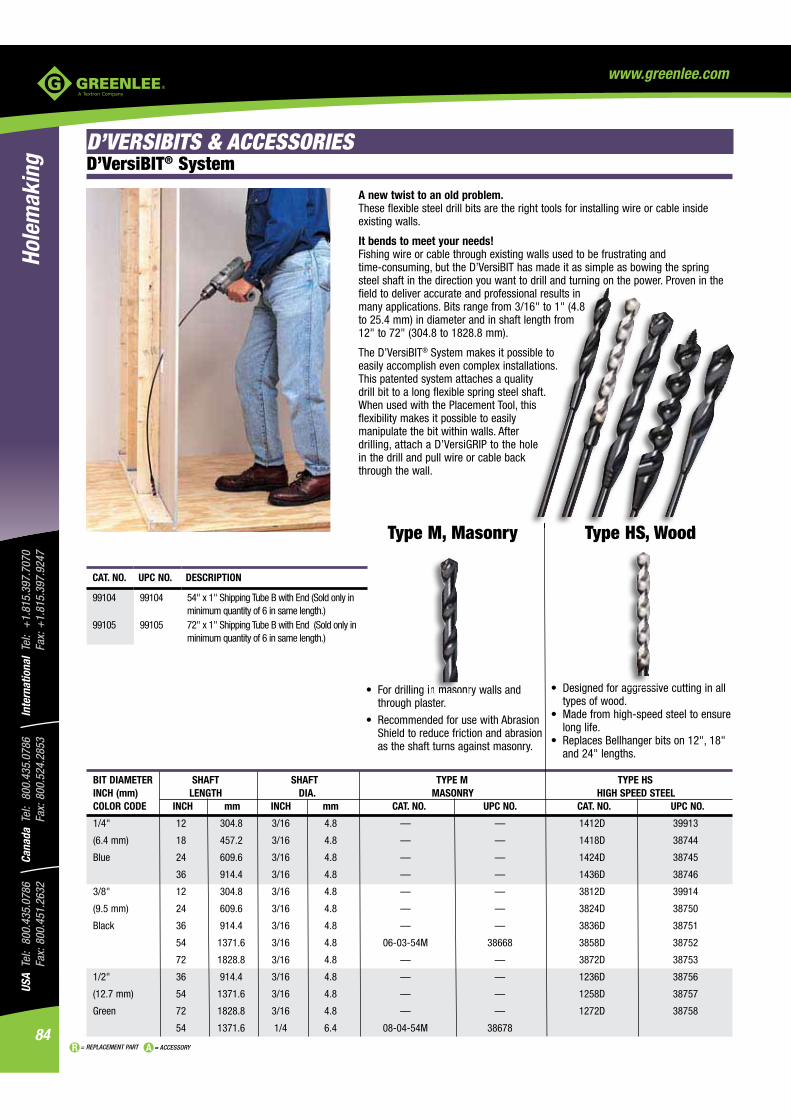
USA
Tel:
800
.435
.078
6
Fax:
800
.451
.263
2Ca
nada
Tel
: 80
0.43
5.07
86
Fax:
800
.524
.285
3In
tern
atio
nal
Tel:
+1.
815.
397.
7070
Fa
x: +
1.81
5.39
7.92
47
84
Hole
mak
ing
= REPLACEMENT PART = ACCESSORY
www.greenlee.com
types of wood.
long life.
and 24" lengths.
through plaster.
Shield to reduce friction and abrasion as the shaft turns against masonry.
BIT DIAMETER SHAFT SHAFT TYPE M TYPE HS INCH (mm) LENGTH DIA. MASONRY HIGH SPEED STEEL COLOR CODE INCH mm INCH mm CAT. NO. UPC NO. CAT. NO. UPC NO.
1/4" 12 304.8 3/16 4.8 — — 1412D 39913
(6.4 mm) 18 457.2 3/16 4.8 — — 1418D 38744
Blue 24 609.6 3/16 4.8 — — 1424D 38745
36 914.4 3/16 4.8 — — 1436D 38746
3/8" 12 304.8 3/16 4.8 — — 3812D 39914
(9.5 mm) 24 609.6 3/16 4.8 — — 3824D 38750
Black 36 914.4 3/16 4.8 — — 3836D 38751
54 1371.6 3/16 4.8 06-03-54M 38668 3858D 38752
72 1828.8 3/16 4.8 — — 3872D 38753
1/2" 36 914.4 3/16 4.8 — — 1236D 38756
(12.7 mm) 54 1371.6 3/16 4.8 — — 1258D 38757
Green 72 1828.8 3/16 4.8 — — 1272D 38758
54 1371.6 1/4 6.4 08-04-54M 38678
Type M, Masonry Type HS, Wood
D’VersiBIT® System
CAT. NO. UPC NO. DESCRIPTION
99104 99104 54" x 1" Shipping Tube B with End (Sold only in minimum quantity of 6 in same length.)
99105 99105 72" x 1" Shipping Tube B with End (Sold only in minimum quantity of 6 in same length.)
D’VERSIBITS & ACCESSORIES
T HS W d
A new twist to an old problem.These flexible steel drill bits are the right tools for installing wire or cable inside existing walls.
It bends to meet your needs!Fishing wire or cable through existing walls used to be frustrating and time- consuming, but the D’VersiBIT has made it as simple as bowing the spring steel shaft in the direction you want to drill and turning on the power. Proven in the field to deliver accurate and professional results in many applications. Bits range from 3/16" to 1" (4.8 to 25.4 mm) in diameter and in shaft length from 12" to 72" (304.8 to 1828.8 mm).
The D’VersiBIT® System makes it possible to easily accomplish even complex installations. This patented system attaches a quality drill bit to a long flexible spring steel shaft.
flexibility makes it possible to easily manipulate the bit within walls. After drilling, attach a D’VersiGRIP to the hole in the drill and pull wire or cable back through the wall.

85
USA Tel: 800.435.0786
Fax: 800.451.2632Canada Tel: 800.435.0786
Fax: 800.524.2853International Tel: +
1.815.397.7070
Fax: +1.815.397.9247
Holemaking
= REPLACEMENT PART = ACCESSORY
www.greenlee.com
BIT DIA. SHAFT SHAFT TYPE A TYPE B TYPE C INCH (mm) LENGTH DIA. AUGER COMBINATION WITH SCREW POINT COMBINATION COLOR CODE INCH mm INCH mm CAT. NO. UPC NO. CAT. NO. UPC NO. CAT. NO. UPC NO.
1/4" 36 914.4 5/32 4.0 — — — — 04-03-36C 38112
(6.4 mm) 54 1371.6 5/32 4.0 — — — — 04-03-54C 38113
Blue 72 1828.8 5/32 4.0 — — — — 04-03-72C 38114
3/8" 36 914.4 3/16 4.8 06-03-36A 38067 06-03-36B 38092 06-03-36C 38117
(9.5 mm) 54 1371.6 3/16 4.8 06-03-54A 38068 06-03-54B 38093 06-03-54C 38118
Black 72 1828.8 3/16 4.8 06-03-72A 38069 06-03-72B 38094 06-03-72C 38119
1/2" 36 914.4 3/16 4.8 08-03-36A 38072 08-03-36B 38097 08-03-36C 38122
(12.7 mm) 54 1371.6 3/16 4.8 08-03-54A 38073 08-03-54B 38098 08-03-54C 38123
Green 72 1828.8 3/16 4.8 08-03-72A 38074 08-03-72B 38099 08-03-72C 38124
9/16" 36 914.4 3/16 4.8 09-03-36A 38077 09-03-36B 38102 — —
(14.3 mm) 54 1371.6 3/16 4.8 09-03-54A 38078 09-03-54B 38103 09-03-54C 38128
Orange 72 1828.8 3/16 4.8 09-03-72A 38079 09-03-72B 38104 09-03-72C 38129
3/4" 36 914.4 1/4 6.4 12-04-36A 38082 — — — —
(19.1 mm) 54 1371.6 1/4 6.4 12-04-54A 38083 — — 12-04-54C 38133
Red 72 1828.8 1/4 6.4 12-04-72A 38084 — — 12-04-72C 38134
1" 36 914.4 1/4 6.4 16-04-36A 38087 — — — —
(25.4 mm) 54 1371.6 1/4 6.4 16-04-54A 38088 — — — —
16-04-72A 38089 — — — —
Type A, Auger Type B, Combination with
Screw Point
Type C, Combination
D'VersiBIT® System
CAT. NO. UPC NO. DESCRIPTION
99104 99104 54" x 1" Shipping Tube B with End (Sold only in minimum quantity of 6 in same length.)
99105 99105 72" x 1" Shipping Tube B with End (Sold only in minimum quantity of 6 in same length.)
D'VersiBIT® Starter Kit
CAT. NO. UPC NO. DESCRIPTION
DBITKIT 01630 D'VersiBIT® Kit with 9/16" Bit, Placement Tool and Grip for
screw point.
avoids walking or skidding.
soft woods or through thin sections.
easy retrieval.
in many types of woods.
and pulling through wood.
this bit can be ground to function like a standard combination bit.
and thick obstacles.
pressure applied.
easily out of the hole.
ENT PAPP RT = ACCESSORY

USA
Tel:
800
.435
.078
6
Fax:
800
.451
.263
2Ca
nada
Tel
: 80
0.43
5.07
86
Fax:
800
.524
.285
3In
tern
atio
nal
Tel:
+1.
815.
397.
7070
Fa
x: +
1.81
5.39
7.92
47
86
Hole
mak
ing
= REPLACEMENT PART = ACCESSORY
www.greenlee.com
change accessories.
any job.
CAT. NO. UPC NO. DESCRIPTION
921-12 12412 Extension, Quick Change 3/16x12921-18 12413 Extension, Quick Change 3/16x18921-24 12414 Extension, Quick Change 3/16x24921-36 12415 Extension, Quick Change 3/16x36125Q 12791 Grip, Quick Change 3/8x1/4150Q 12792 Grip, Quick Change 1/2x1/4168Q 12793 Grip, Quick Change 3/4x1/460A-3/4 12417 Bit, Auger, Quick Change 3/4A921 12411 Quick Change Extension System Kit
SPECIFICATIONS
Quick Connect Extensions
change accessorie
any job
Quick Connect Extensions
EXTENSION SHAFT LENGTH SHAFT DIA. WEIGHT KIT CAT/UPC NO. INCH MM INCH MM LBS. G 921/12411921-12 12 304.8 3/16 4.8 0.2 90.72 921-18 18 457.2 3/16 4.8 0.25 113.4 1921-24 24 609.6 3/16 4.8 0.3 136.08 921-36 36 914.4 3/16 4.8 0.4 181.44 1 WEIGHT KIT CAT/UPC NO.GRIP CAPACITY MM LBS. G 921/12411125Q 100LBS – 0.04 18.144 150Q 100LBS – 0.05 22.68 1 168Q 100LBS – 0.06 27.216 HOLE DIA. HEX SHANK WEIGHT KIT CAT/UPC NO.AUGER BIT INCH MM INCH MM LBS. G 921/1241160A-3/4 3/4 19.1 1/4 6.4 0.6 272.16 1
60A-3/4

87
USA Tel: 800.435.0786
Fax: 800.451.2632Canada Tel: 800.435.0786
Fax: 800.524.2853International Tel: +
1.815.397.7070
Fax: +1.815.397.9247
Holemaking
= REPLACEMENT PART = ACCESSORY
www.greenlee.com
USE WITH CAT. NO. UPC NO. SHAFT DIA. LENGTH
3XT 36 38685 3/16" (4.8 mm) 36" (914.4 mm)
3XT 54 38686 3/16" (4.8 mm) 54" (1371.6 mm)
3XT 72 38687 3/16" (4.8 mm) 72" (1828.8 mm)
4XT 36 38688 1/4" (6.4 mm) 36" (914.4 mm)
4XT 54 38689 1/4" (6.4 mm) 54" (1371.6 mm)
4XT 72 38690 1/4" (6.4 mm) 72" (1828.8 mm)
Extensions
® shaft to increase the length of the bit.
SPECIFICATIONS
Size 3XT 36, 3XT 54, 3XT 72 - connecting end diameter 7/16" (11.1 mm) 4XT 36, 4XT 54, 4XT 72 - connecting end diameter 5/8" (15.9 mm)
SPECIFICATIONS
Placement Tool
Wire and Cable Pulling Grips
Abrasion Shield
accidentally drilling through the wall.
SPECIFICATIONS
Function Protects shaft and hand while drilling with any size or type D'VersiBIT®.
Length 48" (1219.2 mm)
CAT. NO. UPC NO. DESCRIPTION
606AS 38696 Abrasion Shield
CAT. NO. UPC NO. DESCRIPTION
712P 38350 D'VersiBIT® Placement Tool
SPECIFICATIONS
Function Use to position all bit and shaft sizes.
SPECIFICATIONS
Function Protects shaft and hand while drilling with any size
C
7
S
F
® or to any standard 1/4 Quick Connect adapter.
CAT. NO. UPC NO. DESCRIPTION
125Q 12791(9.5 mm to 12.7 mm).
150Q 127921/2" to 9/16" (12.7 to 14.3 mm).
168Q 127933/4" to 1" (19.1 to 25.4 mm).
SPECIFICATIONS
Function For pulling wire, cable or fish tape through walls.Pulling Strength 100 lbs.
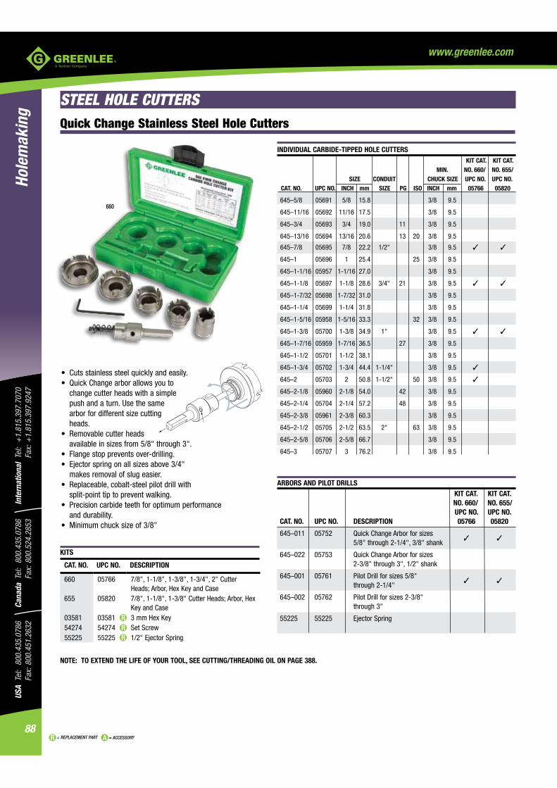
USA
Tel:
800
.435
.078
6
Fax:
800
.451
.263
2Ca
nada
Tel
: 80
0.43
5.07
86
Fax:
800
.524
.285
3In
tern
atio
nal
Tel:
+1.
815.
397.
7070
Fa
x: +
1.81
5.39
7.92
47
88
Hole
mak
ing
= REPLACEMENT PART = ACCESSORY
www.greenlee.com
STEEL HOLE CUTTERS
change cutter heads with a simple push and a turn. Use the same arbor for different size cutting heads.
available in sizes from 5/8" through 3".
makes removal of slug easier.
split-point tip to prevent walking.
and durability.
KITS
INDIVIDUAL CARBIDE-TIPPED HOLE CUTTERS KIT CAT. KIT CAT.
MIN. NO. 660/ NO. 655/ SIZE CONDUIT CHUCK SIZE UPC NO. UPC NO. CAT. NO. UPC NO. INCH mm SIZE PG ISO INCH mm 05766 05820
645 –5/8 05691 5/8 15.8 3/8 9.5
645–11/16 05692 11/16 17.5 3/8 9.5
645–3/4 05693 3/4 19.0 11 3/8 9.5
645–13/16 05694 13/16 20.6 13 20 3/8 9.5
645–7/8 05695 7/8 22.2 1/2" 3/8 9.5
645–1 05696 1 25.4 25 3/8 9.5
645– 1-1/16 05957 1-1/16 27.0 3/8 9.5
645–1-1/8 05697 1-1/8 28.6 3/4" 21 3/8 9.5
645–1-7/32 05698 1-7/32 31.0 3/8 9.5
645–1-1/4 05699 1-1/4 31.8 3/8 9.5
645–1-5/16 05958 1-5/16 33.3 32 3/8 9.5
645–1-3/8 05700 1-3/8 34.9 1" 3/8 9.5
645–1-7/16 05959 1-7/16 36.5 27 3/8 9.5
645–1-1/2 05701 1-1/2 38.1 3/8 9.5
645–1-3/4 05702 1-3/4 44.4 1-1/4" 3/8 9.5
645–2 05703 2 50.8 1-1/2" 50 3/8 9.5
645–2-1/8 05960 2-1/8 54.0 42 3/8 9.5
645–2-1/4 05704 2-1/4 57.2 48 3/8 9.5
645–2-3/8 05961 2-3/8 60.3 3/8 9.5
645–2-1/2 05705 2-1/2 63.5 2" 63 3/8 9.5
645–2-5/8 05706 2-5/8 66.7 3/8 9.5
645–3 05707 3 76.2 3/8 9.5
ARBORS AND PILOT DRILLS KIT CAT. KIT CAT. NO. 660/ NO. 655/ UPC NO. UPC NO. CAT. NO. UPC NO. DESCRIPTION 05766 05820
645–011 05752 Quick Change Arbor for sizes 5/8" through 2-1/4", 3/8" shank
645–022 05753 Quick Change Arbor for sizes 2-3/8" through 3", 1/2" shank
645–001 05761 Pilot Drill for sizes 5/8" through 2-1/4"
645–002 05762 Pilot Drill for sizes 2-3/8" through 3"
55225 55225 Ejector Spring
660
CAT. NO. UPC NO. DESCRIPTION
660 05766 7/8", 1-1/8", 1-3/8", 1-3/4", 2" Cutter
655 05820Key and Case
03581 03581 3 mm Hex Key54274 54274 Set Screw55225 55225 1/2" Ejector Spring
Quick Change Stainless Steel Hole Cutters
NOTE: TO EXTEND THE LIFE OF YOUR TOOL, SEE CUTTING/THREADING OIL ON PAGE 388.

89
USA Tel: 800.435.0786
Fax: 800.451.2632Canada Tel: 800.435.0786
Fax: 800.524.2853International Tel: +
1.815.397.7070
Fax: +1.815.397.9247
Holemaking
= REPLACEMENT PART = ACCESSORY
www.greenlee.com
KIT
REPLACEMENT PILOT DRILLS
CUTTER SIZE RANGE PILOT DRILL HEX SET SCREW WT. INCH mm CAT. NO. UPC NO. SIZE CAT./UPC NO. LBS. g
3/4-2 19.0-50.8 625–001 39872◊ 3 mm 54274 .19 86
2-1/2 63.5 625–002 38390 4 mm 54295 .28 127
◊ Point of Purchase Package
CARBIDE-TIPPED HOLE CUTTERS KIT CAT.
MIN. NO. 635/ SIZE CONDUIT CHUCK SIZE WEIGHT UPC NO. CAT. NO. UPC NO. INCH mm SIZE PG ISO INCH mm LBS. g 03599
625–3/4 38324 3/4 19.0 11 1/4 6.4 .02 9
625–13/16 38325 13/16 20.6 13 20 1/4 6.4 .02 9
625–7/8 38326 7/8 22.2 1/2" 16 1/4 6.4 .33 150
625–1 38327 1 25.4 25 3/8 9.5 .02 9
625–1-1/8 38328 1-1/8 28.6 3/4" 21 3/8 9.5 .43 195
625–1-7/32 38329 1-7/32 30.5 3/8 9.5 .44 200
625 –1-1/4 38330 1-1/4 31.7 3/8 9.5 .33 150
625–1-3/8 38331 1-3/8 35.0 1" 3/8 9.5 .47 213
625–1-1/2 38332 1-1/2 38.1 3/8 9.5 .37 168
625–1-3/4 38333 1-3/4 44.4 1-1/4" 3/8 9.5 .40 182
625–2 38334 2 50.8 1-1/2" 50 3/8 9.5 .50 227
625–2-1/2 38336 2-1/2 63.5 2" 1/2 12.7 .67 304
All hole cutters are packaged in Point of Purchase blister pack.
Carbide-Tipped Hole Cutters
aluminum, steel.
CAT. NO. UPC NO. DESCRIPTION
635 03599
SPECIFICATIONS
Maximum Cutting Depth 8 ga. (4 mm)
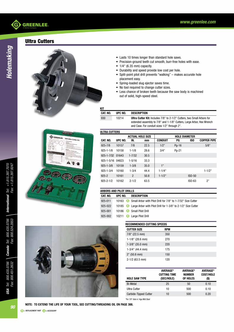
USA
Tel:
800
.435
.078
6
Fax:
800
.451
.263
2Ca
nada
Tel
: 80
0.43
5.07
86
Fax:
800
.524
.285
3In
tern
atio
nal
Tel:
+1.
815.
397.
7070
Fa
x: +
1.81
5.39
7.92
47
90
Hole
mak
ing
= REPLACEMENT PART = ACCESSORY
www.greenlee.com
Ultra Cutters
RECOMMENDED CUTTING SPEEDS
CUTTER SIZE RPM
7/8" (22.5 mm) 350
1-1/8" (28.6 mm) 270
1-3/8" (35.0 mm) 220
1-3/4" (44.4 mm) 175
2" (50.8 mm) 150
2-1/2 (63.5 mm) 120
AVERAGE* AVERAGE* AVERAGE* CUTTING TIME NUMBER COST/HOLEHOLE SAW TYPE (SEC/HOLE) OF HOLES ($)
Bi-Metal 25 50 0.10
Ultra Cutter 10 500 0.10
Carbide-Tipped Cutter 10 500 0.20
*For 7/8" Hole in 14ga Mild Steel
placement easy.
out of solid, high-speed steel.
ULTRA CUTTERS ACTUAL HOLE SIZE HOLE DIAMETER CAT. NO. UPC NO. IN. mm CONDUIT PG ISO COPPER PIPE
925-7/8 10157 7/8 22.5 1/2" Pg-16 5/8"
925-1-1/8 10158 1-1/8 28.6 3/4" Pg-21
925-1-7/32 01643 1-7/32 30.5
925-1-5/16 04823 1-5/16 33.3
925-1-3/8 10159 1-3/8 35.0 1"
925-1-3/4 10160 1-3/4 44.4 1-1/4" 1-1/2"
925-2 10161 2 50.8 1-1/2" ISO-50
925-2-1/2 10162 2-1/2 63.5 ISO-63 2"
ARBORS AND PILOT DRILLS
CAT. NO. UPC NO. DESCRIPTION
925-011 10163 Small Arbor with Pilot Drill for 7/8" to 1-7/32" Size Cutter
925-022 10185 Large Arbor with Pilot Drill for 1-3/8" to 2-1/2" Size Cutter
925-001 10186 Small Pilot Drill
925-002 10211 Large Pilot Drill
NOTE: TO EXTEND THE LIFE OF YOUR TOOL, SEE CUTTING/THREADING OIL ON PAGE 388.
KIT CAT. NO. UPC NO. DESCRIPTION
930 10214 Ultra Cutter Kit: Includes 7/8" to 2-1/2" Cutters, two Small Arbors for
and Case. For conduit sizes 1/2" through 2".

91
USA Tel: 800.435.0786
Fax: 800.451.2632Canada Tel: 800.435.0786
Fax: 800.524.2853International Tel: +
1.815.397.7070
Fax: +1.815.397.9247
Holemaking
= REPLACEMENT PART = ACCESSORY
www.greenlee.com
Quick Change Hole Saw Kit
CAT. NO. UPC NO. DESCRIPTION
830QS 10915 Quick Change Hole Saw Kit for 1/2" through 2" Conduit Sizes
02800 02800 5/16" Arbor, Minimum Chuck Size 3/8"02801 02801 7/16" Arbor, Minimum Chuck Size 1/2"02802 02802 Retrofit Kit - upgrade 3 Hole Saws up to 1-9/16" to Quick
Change02803 02803 Small Adapters for 9/16" to 1-9/16" Saws Qty. 1002804 02804 Large Adapters for 1-5/8" to 6" Saws Qty. 302805826S
0280512787
Bushings for 1-1/4" to 1-9/16" Saws Qty. 5Hole saw stops
SPECIFICATIONS
Shank Available for 3/8" and heavy duty 1/2" chuck sizesArbor length 5-1/2" with pilot drillArbor weight 0.5 lbs (227 g)Arbor operationArbor pilot drill 37623, 4-1/8" x 1/4" (104.8 mm x 6.4 mm)
Quick Change Arbor Features:
2. Provides better ergonomics - reduces stress on wrist, arm and hand.3. Eliminates obstructed view from hole saw.
for hole saws above 2-1/2").
Kit contains Bi-metal hole saws for 1/2" through 2" conduit sizes. See page 82 for details.
02802
Deburring Tool
saving time and labor.
being cut on sharp edges.
SPECIFICATIONS
Material thickness Deburrs up to 10 gaugeMaterial type Mild and stainless steel, copper, brass, aluminumShank Minimum chuck size 3/8"Cutter size 13/16" diameterOperation Run tool clockwise to deburr, counterclockwise to clear chips
CAT. NO. UPC NO. DESCRIPTION
11170 11170 Deburring Tool11180 11180 Cutter 3-pack
C
8
000
0008
SP
KiSe
CAT. NO. UPC NO. DESCRIPTION
11170 11170 Deburring Tool11180 11180 Cutter 3-pack
02802
NOTE: TO EXTEND THE LIFE OF YOUR TOOL, SEE CUTTING/THREADING OIL ON PAGE 388.
A

USA
Tel:
800
.435
.078
6
Fax:
800
.451
.263
2Ca
nada
Tel
: 80
0.43
5.07
86
Fax:
800
.524
.285
3In
tern
atio
nal
Tel:
+1.
815.
397.
7070
Fa
x: +
1.81
5.39
7.92
47
92
Hole
mak
ing
= REPLACEMENT PART = ACCESSORY
www.greenlee.com
Bi-Metal Hole Saws
HOLE SAWS
2" x 4" wood studs.
outlast competitor's blades. That beats premature saw replacement and saves you money.
cooler for longer life and better performance.
*See page 91 for Quick Change adapter information.
USE WITH USE WITH WEIGHT ACTUAL HOLE SIZE HOLE DIA. QUICK CHANGE STD. CAT. NO. UPC NO. INCH mm CONDUIT PG ISO COPPER PIPE SIZE ARBOR NO. ARBOR NO. LBS. g
825–9/16 19131 9/16 14.3 1/8" .1 46 825–5/8 19132 5/8 15.9 Pg-9 1/4" .1 46 825–11/16 19133 11/16 17.5 ISO-16 3/8" .1 46 825–3/4 19134 3/4 19.0 Pg-11 1/2" .1 46 825–13/16 19135 13/16 20.6 Pg-13 ISO-20 1/2" .1 46 825–7/8 19136 7/8 22.2 1/2" Pg-16 5/8" .1 46 825–15/16 19137 15/16 23.8 .1 46 825–1 19138 1 25.4 ISO-25 3/4" .1 46 825–1-1/16 19140 1-1/16 27.0 .1 46 825–1-1/8 19141 1-1/8 28.6 3/4" Pg-21 3/4" .1 46 825–1-3/16 19143 1-3/16 30.2 .2 91 825–1-1/4 19144 1-1/4 31.7 1" .2 91 825–1-5/16 19145 1-5/16 33.3 ISO-32 .2 91 825–1-3/8 19146 1-3/8 35.0 1" .1 46 825–1-7/16 19147 1-7/16 36.5 Pg-29 .2 91 825–1-1/2 19148 1-1/2 38.1 1-1/4" .2 91 825–1-9/16 19149 1-9/16 39.7 .2 91 825–1-5/8 19150 1-5/8 41.3 ISO-40 .2 91 825–1-11/16 19151 1-11/16 42.9 .3 137 825–1-3/4 19152 1-3/4 44.4 1-1/4" 1-1/2" .2 91 825–1-13/16 19153 1-13/16 46.0 .2 91 825–1-7/8 19154 1-7/8 47.6 Pg-36 .3 137 825–2 19155 2 50.8 1-1/2" ISO-50 .2 91 825–2-1/16 19157 2-1/16 52.4 .3 137 825–2-1/8 19158 2-1/8 54.0 Pg-42 .3 137 825–2-1/4 19159 2-1/4 57.2 2" .3 137 825–2-5/16 19160 2-5/16 58.7 .5 227 825–2-3/8 19161 2-3/8 60.3 Pg-48 2" .3 137 825–2-1/2 19162 2-1/2 63.5 2" ISO-63 2" .3 137 825–2-9/16 19163 2-9/16 65.0 .4 182 825-2-5/8 19164 2-5/8 66.7 .4 182 825–2-3/4 19165 2-3/4 69.8 .4 182 825–2-7/8 19166 2-7/8 73.0 .4 182 825–3 19167 3 76.2 2-1/2" 2-1/2" .5 227 825–3-1/8 19168 3-1/8 79.4 .5 227 825–3-1/4 19169 3-1/4 82.5 .6 273 825–3-3/8 19170 3-3/8 85.7 .6 273 825–3-1/2 19171 3-1/2 88.9 .6 273 825–3-5/8 19172 3-5/8 92.1 3" .6 273 825–3-3/4 19174 3-3/4 95.2 .7 318 825–3-7/8 19175 3-7/8 98.4 3-1/2" .7 318 825–4 19176 4 101.6 .7 318 825–4-1/8 19177 4-1/8 104.8 3-1/2" 3-1/2" .8 363 825–4-1/4 19178 4-1/4 108.0 4" .8 363 825–4-3/8 19179 4-3/8 111.1 .8 363 825–4-1/2 19180 4-1/2 114.3 4" .9 409 825–4-3/4 19181 4-3/4 120.6 1.1 499 825–5 19182 5 127.0 1.2 545 825–5-1/2 19183 5-1/2 139.7 5" 1.2 545 825–6 19184 6 152.4 1.4 636
37157, 37155,
or 38522
37156 or 37154
37156
37156
02800*
02801*

93
USA Tel: 800.435.0786
Fax: 800.451.2632Canada Tel: 800.435.0786
Fax: 800.524.2853International Tel: +
1.815.397.7070
Fax: +1.815.397.9247
Holemaking
= REPLACEMENT PART = ACCESSORY
www.greenlee.com
Bi-Metal Hole Saws with Stops
personal preference.
CAT. NO. UPC NO. DESCRIPTION
826S 12787 Hole saw stop (Qty. 3)830S 10912
PILOT DRILL
CARBIDE GRIT HOLE SAWS ACTUAL HOLE SIZE HOLE DIAMETER CAT. NO. UPC NO. INCH mm CONDUIT PG ISO
725–7/8 10072 7/8 22.2 1/2" 16
725–1-1/8 10073 1-1/8 28.6 3/4" 21
725–1-3/8 10075 1-3/8 35.0 1"
725–1-1/2 10076 1-1/2 38.1
725–1-3/4 10077 1-3/4 44.4 1-1/4"
725–2 10078 2 50.8 1-1/2" 50
725–2-1/8 10079 2-1/8 54.0
725–2-1/2 10080 2-1/2 63.5 2" 63
725–3-5/8 10081 3-5/8 92.1 3"
725–4-1/8 10687 4-1/8 104.8 3-1/2"
725–4-1/2 01879 4-1/2 114.3 4"
Carbide-Grit Hole Saws
CAT. NO. UPC NO. DESCRIPTION
725-001 10082 1/4" Carbide Tipped Pilot Drill
smooth cuts through tile, cement board, and other abrasive materials. Perfect for cutting holes in Quazite® enclosure or hardy board siding for 3-0 box installation.
USE WITH USE WITH WEIGHT ACTUAL HOLE SIZE HOLE DIA. QUICK CHANGE STD. CAT. NO. UPC NO. INCH mm CONDUIT PG ISO COPPER PIPE SIZE ARBOR NO. ARBOR NO. LBS. g
826S–7/8
826S–1-1/8
826S–1-3/8
826S–1-3/4
826S–2
826S–2-1/2
02800*
02801*
37157, 37155,
or 38522
37156 or 37154
37156

USA
Tel:
800
.435
.078
6
Fax:
800
.451
.263
2Ca
nada
Tel
: 80
0.43
5.07
86
Fax:
800
.524
.285
3In
tern
atio
nal
Tel:
+1.
815.
397.
7070
Fa
x: +
1.81
5.39
7.92
47
94
Hole
mak
ing
= REPLACEMENT PART = ACCESSORY
www.greenlee.com
ARBORS
Cat./UPC No. Standard Pack N/A 37157 38522 37155 N/A 37154 37156 Point of Purchase Pack 02800 38507 38524 38505 02801 38504 38506 Bulk Pack N/A 37157B/37630 38522B/38529 37155B/37628 N/A 37154B/37903 37156B/37626 Shank Hex Round with 3 flats Hex Hex Hex Hex Hex Shank Size 5/16" (7.9 mm) 1/4" (6.4 mm) 5/16" (7.9 mm) 7/16" (11.1 mm) 7/16" (11.1 mm) 5/16" (7.9 mm) 7/16" (11.1 mm) Min. Chuck Size 3/8" (9.5 mm) 1/4" (6.4 mm) 3/8" (9.5 mm) 1/2" (12.7 mm) 1/2" (12.7 mm) 3/8" (9.5 mm) 1/2" (12.7 mm) Use With 9/16" - 2" 9/16" - 1-3/16" 9/16" - 1-3/16" 9/16" - 1-3/16" 9/16"-6" 1-1/4" - 2" 1-1/4" - 6" (14.3 - 50.8 mm) (14.3 - 30.2 mm) (14.3 - 30.2 mm) (14.3 - 30.2 mm) (14.3 - 152.4mm) (31.8 - 50.8 mm) (31.8 - 152.4 mm) Hole Saws Hole Saws Hole Saws Hole Saws Hole Saws and all Greenlee Recessed Light Hole Saws Weight 0.5 lbs (227 g) .2 lbs (91 g) .2 lbs (91 g) .2 lbs (91 g) 0.5 lbs. (227 g) .5 lbs (227 g) .5 lbs. (227 g)
HIGH-SPEEDSTEEL PILOTDRILLS
Cat./UPC No.
Standard Pack 37623 38526
Point of Purchase Pack 39873 39893
Bulk Pack Qty: 50 per pack 37624 38991
Length 4-1/8" 3-1/4" (104.8 mm) (82.5 mm)
Diameter 1/4" 1/4" (6.4 mm) (6.4 mm)
Use With 37154, 37155, 37154, 37155, Greenlee 37156 & 37156 & Arbor #’s 37157 38522
Weight .2 lbs (91 g) .2 lbs (91 g)* Quazite is a registered trademark of Strongwell Corporation.
Arbors with Replacement High-Speed Steel Pilot Drill Bits
See page 86 for Quick Change adapter information.
CARBIDE-TIPPED PILOTDRILLS
Cat./UPC No.
Standard Pack 10082
Length 4-1/8" (104.8 mm)
Diameter 1/4" (6.4 mm)
Use With 37157, 37155, Greenlee 37156 & Arbor #’s 37154
Weight .2 lbs (91 g)

95
USA Tel: 800.435.0786
Fax: 800.451.2632Canada Tel: 800.435.0786
Fax: 800.524.2853International Tel: +
1.815.397.7070
Fax: +1.815.397.9247
Holemaking
= REPLACEMENT PART = ACCESSORY
www.greenlee.com
830 / 19192
834 / 19913
890 / 03479 891 / 03480
889 / 03478
WEIGHT CAT. NO. UPC NO. DESCRIPTION LBS. kg 830 19192 Hole Saw Kit for 1/2" through 2" Conduit Sizes 2.7 1.2 834 19913 Hole Saw Kit for 2-1/2" through 4" Conduit Sizes 6.2 2.8 835 27538 Hole Saw Kit for 1/2" through 4" Conduit Sizes 7.7 3.5 830Pg 29209 Hole Saw Kit for Pg-9 through Pg-48 2.7 1.2 889 03478 Plumber’s Hole Saw Kit – 3/4" through 2-1/4" Conduit Sizes 2.3 1.0 890 03479 Industrial Maintenance Hole Saw Kit – 3/4" through 4-3/4" Conduit Sizes 9.7 4.4 891 03480 Electrician’s/Plumber’s Hole Saw Kit - 3/4" through 2-1/2" Conduit Sizes 3.5 1.6
KIT CAT./UPC NO. 830/ 834/ 835/ 830PG/ 889/ 890/ 891/
CAT. NO. UPC NO. DESCRIPTION 19192 19913 27538 29209 03478 03479 03480
825–3/4 19134 3/4" Hole Saw 825–7/8 19136 7/8" Hole Saw 825–1 19138 1" Hole Saw 825–1-1/8 19141 1-1/8" Hole Saw 825–1-3/8 19146 1-3/8" Hole Saw 825–1-1/2 19148 1-1/2" Hole Saw 825–1-3/4 19152 1-3/4" Hole Saw 825–2 19155 2" Hole Saw 825–2-1/4 19159 2-1/4" Hole Saw 825–2-1/2 19162 2-1/2" Hole Saw 825–3 19167 3" Hole Saw 825–3-1/4 19169 3-1/4" Hole Saw 825–3-5/8 19172 3-5/8" Hole Saw 825–3-3/4 19174 3-3/4" Hole Saw 825–4-1/8 19177 4-1/8" Hole Saw 825–4-1/2 19180 4-1/2" Hole Saw 825–4-3/4 19181 4-3/4" Hole Saw 825–5/8 19132 Pg-9 (15.9 mm) Hole Saw 825–3/4 19134 Pg-11 (19.0 mm) Hole Saw 825–13/16 19135 Pg-13 (20.6 mm) Hole Saw 825–1-3/16 19143 30.2 mm Hole Saw 825–1-1/2 19148 Pg-29 (38.1 mm) Hole Saw 825–1-7/8 19154 Pg-36 (47.6 mm) Hole Saw 825–2-3/8 19161 Pg-48 (60.3 mm) Hole Saw 38522 38522 Arbor w/Pilot Drill (2) 37157 37157 Arbor w/Pilot Drill 37155 37155 Arbor w/Pilot Drill 37156 37156 Arbor w/Pilot Drill 38526 38526 Pilot Drill
Bi-Metal Hole Saw Kits
most commonly used Greenlee variable pitch hole saw sizes and arbors.
830 / 19192
834 / 19913
835 / 27538
90 / 03479 891 / 03480
889 / 03478

USA
Tel:
800
.435
.078
6
Fax:
800
.451
.263
2Ca
nada
Tel
: 80
0.43
5.07
86
Fax:
800
.524
.285
3In
tern
atio
nal
Tel:
+1.
815.
397.
7070
Fa
x: +
1.81
5.39
7.92
47
96
Hole
mak
ing
= REPLACEMENT PART = ACCESSORY
www.greenlee.com
CAT./ HOLE WEIGHT UPC NO. DESCRIPTION DIAMETER LBS. kg USE FOR 35712 Steel Toothed 4-3/8" (111 mm) .76 .34 Mini Juno, Capri, 35716 Carbide Grit 4-3/8" (111 mm) .74 .34 Marco and Halo 35713 Steel Toothed 6-3/8" (162 mm) 1.2 .54 Halo and Capri 35717 Carbide Grit 6-3/8" (162 mm) 1.1 .50 Halo and Capri 35714 Steel Toothed 6-5/8" (168 mm) 1.3 .59 Juno and Progress 35718 Carbide Grit 6-5/8" (168 mm) 1.3 .59 Juno and Progress 35715 Steel Toothed 6-7/8" (175 mm) 1.3 .59 Lithonia, Marco, 35719 Carbide Grit 6-7/8" (175 mm) 1.4 .64 Lightolier, Progress, Capri and Precolite
Recessed Light Hole Saws
lighting fixtures.
SPECIFICATIONS
Capacity Steel Toothed Blade - up to 7/8" (22.2 mm) plywood, wood, acoustical tile and ceiling tile. Carbide Grit Blade - up to 7/8" (22.2 mm) drywall, plywood, wood, acoustical tile, ceiling tile, plaster and stucco.
RECESSED LIGHT HOLE SAWS
Quick Cutter™ Hole Saws
installations.
in very abrasive materials and still stay sharp.
tool when drilling drywall.
CAT. NO. UPC NO. DESCRIPTION
06923 06923 Quick Cutter Recessed Hole Saw, Adjustable in 1/2" Increments for Cuts of 2-1/2" to 7"
CAT. NO. UPC NO. DESCRIPTION
35720 35720 Blade for 3571235721 35721 Blade for 3571335722 35722 Blade for 3571435723 35723 Blade for 3571535724 35724 Blade for 3571635725 35725 Blade for 3571735726 35726 Blade for 3571835727 35727 Blade for 3571935708 35708 Set of 5 Blade Screws

97
USA Tel: 800.435.0786
Fax: 800.451.2632Canada Tel: 800.435.0786
Fax: 800.524.2853International Tel: +
1.815.397.7070
Fax: +1.815.397.9247
Holemaking
= REPLACEMENT PART = ACCESSORY
www.greenlee.com
Recommended Hole Saw Cutting Speeds
RPM HOLE SAW SIZE INCH mm MILD STEEL CAST IRON BRASS ALUMINUM 9/16 14.3 580 400 790 900
5/8 15.9 550 365 730 825
11/16 17.5 500 330 665 750
3/4 19.0 460 300 600 690
13/16 20.6 425 280 560 635
7/8 22.2 390 260 520 585
15/16 23.8 370 245 495 555
1 25.4 350 235 470 525
1-1/16 27.0 325 215 435 480
1-1/8 28.6 300 200 400 450
1-3/16 30.2 285 190 380 425
1-1/4 31.7 275 180 360 410
1-5/16 33.3 260 175 345 390
1-3/8 35.0 250 165 330 375
1-7/16 36.5 240 160 315 360
1-1/2 38.1 230 150 300 345
1-9/16 39.7 220 145 290 330
1-5/8 41.3 210 140 280 315
1-11/16 42.9 205 135 270 305
1-3/4 44.4 195 130 260 295
1-13/16 46.0 190 125 250 285
1-7/8 47.6 180 120 240 270
2 50.8 170 115 230 255
2-1/16 52.4 165 110 220 245
2-1/8 54.0 160 105 210 240
2-1/4 57.2 150 100 200 225
RPM HOLE SAW SIZE INCH mm MILD STEEL CAST IRON BRASS ALUMINUM 2-5/16 58.7 150 100 195 225
2-3/8 60.3 140 95 190 200
2-1/2 63.5 135 90 180 205
2-9/16 65.0 130 85 175 200
2-5/8 66.7 130 85 170 195
2.677 68.0 125 80 160 185
2-3/4 69.8 125 80 160 185
2-7/8 73.0 120 80 160 180
2.913 74.0 115 75 150 170
3 76.2 115 75 150 170
3-1/8 79.4 110 70 140 165
3-1/4 82.5 105 70 140 155
3-3/8 85.7 100 65 130 150
3-1/2 88.9 95 65 130 145
3-5/8 92.1 95 60 120 140
3-3/4 95.2 90 60 120 135
3-7/8 98.4 90 60 120 135
4 101.6 85 55 110 130
4-1/8 104.8 80 55 110 120
4-1/4 108.0 80 55 110 120
4-3/8 111.1 80 50 100 120
4-1/2 114.3 75 50 100 105
4-3/4 120.6 75 50 95 95
5 127.0 65 45 90 90
5-1/2 139.7 60 35 85 85
6 152.4 55 35 75 75

USA
Tel:
800
.435
.078
6
Fax:
800
.451
.263
2Ca
nada
Tel
: 80
0.43
5.07
86
Fax:
800
.524
.285
3In
tern
atio
nal
Tel:
+1.
815.
397.
7070
Fa
x: +
1.81
5.39
7.92
47
98
Hole
mak
ing
= REPLACEMENT PART = ACCESSORY
www.greenlee.com
Reciprocating Blades
SAW BLADES
RECIPROCATING SAW BLADES LENGTH x WIDTH x THICKNESS TEETH QTY.
CAT. NO. UPC NO. INCHES mm PER INCH TYPE APPLICATION PER PK. 353-123 09963 6 x 3/4 x .035 152 x 19.05 x .889 Progressive Bimetal, Metal 5 Straight 353-318 09961 4 x 5/16 x .035 101 x 7.938 x .889 18 Bimetal, Metal 5 Scroll 353-418 09962 4 x 3/4 x .035 101 x 19.05 x .889 18 Bimetal, Metal 5 Straight 353-614 09964 6 x 3/4 x .035 152 x 19.05 x .889 14 Bimetal, Metal 5 Straight 353-618 09965 6 x 3/4 x .035 152 x 19.05 x .889 18 Bimetal, Metal 5 Straight 353-624 09966 6 x 3/4 x .035 152 x 19.05 x .889 24 Bimetal, Metal 5 Straight 353-804 09977 8 x 3/4 x .050 203 x 19.05 x 1.27 10/14 Bimetal, Metal 2 Straight 353-814 09975 8 x 3/4 x .050 203 x 19.05 x 1.27 14 Bimetal, Metal 2 Straight 353-818 09976 8 x 3/4 x .050 203 x 19.05 x 1.27 18 Bimetal, Metal 2 Straight 353-234 09991 8 x 3/4 x .050 203 x 19.05 x 1.27 Progressive Taper 353-656 Taper 353-646 Straight 353-956 Straight 353-156 Straight
353-966 09979 9 x 7/8 x .062 228 x 22.23 x 1.56 6 Bimetal, Taper 353-969 09990 9 x 7/8 x .062 228 x 22.23 x 1.56 8/10 Bimetal, Metal Demolition 2 Taper
353-345 09972 8 x 3/4 x .050 203 x 19.05 x 1.27 Progressive Bimetal, General 5 Taper
W BLADESLENGTH x WIDTH x x THICKNESS TEETH QTY.YY
CAT. NO.CC UPC NO. INCHES mm PER INCH TYPE APPLICATION PER PK.
16-gauge metal stud strutEMT conduit thick wall pipe rod/rebar
Metal
Wood
Demolition
Specialty

99
USA Tel: 800.435.0786
Fax: 800.451.2632Canada Tel: 800.435.0786
Fax: 800.524.2853International Tel: +
1.815.397.7070
Fax: +1.815.397.9247
Holemaking
= REPLACEMENT PART = ACCESSORY
www.greenlee.com
Jig Saw Blades
JIG SAW BLADES CAT. NO. UPC NO. DESCRIPTION TEETH TYPE APPLICATION TEETH PER INCH QTY. PER PK. 373-U123 09994 3-5/8" Univeral Jig Saw Blade Progressive High-speed Steel Metal 18 5 373-U234 373-U345 09995 5" Universal Jig Saw Blade Progressive Bimetal General 18 5 373-U300 09996 2-3/4" Universal Jig Saw Blade Grit Carbide Grit Abrasive Materials 18 2 373-UVAR Variety Pack 373-U234 and General 373-U345 373-T123 10004 4" T-Shank Jig Saw Blade Progressive High-speed Steel Metal 18 3 373-T234 373-T345 10005 5-1/4" T-Shank Jig Saw Blade Progressive Bimetal General 18 5 373-TVAR Variety Pack 373-T234 and General 373-T345
- No teeth to snag, cuts efficiently on both up and down strokes for extra smooth finishes. - Additional cutting application for cast iron, tile, pipe, ceramic.
FLEXIBLE CONDUIT CUTTERSFlex Splitter® MC and Flexible Conduit Cutter
easy twist of the conduit.
blades per package.
CAT. NO. UPC NO. DESCRIPTION
1940 34953 Flex Splitter® Flexible Metal Conduit Cutter1941-1 00288 Single Blade for 19401941-5 33735 5 Pack Blades for 1940
SPECIFICATIONS
Capacity 14/2 to 10/4 BX 3/8" flexible metal conduitWeight 1940 - 4 lbs. (1.8 kg)
CAT NO UPC NO DESCRIPTION
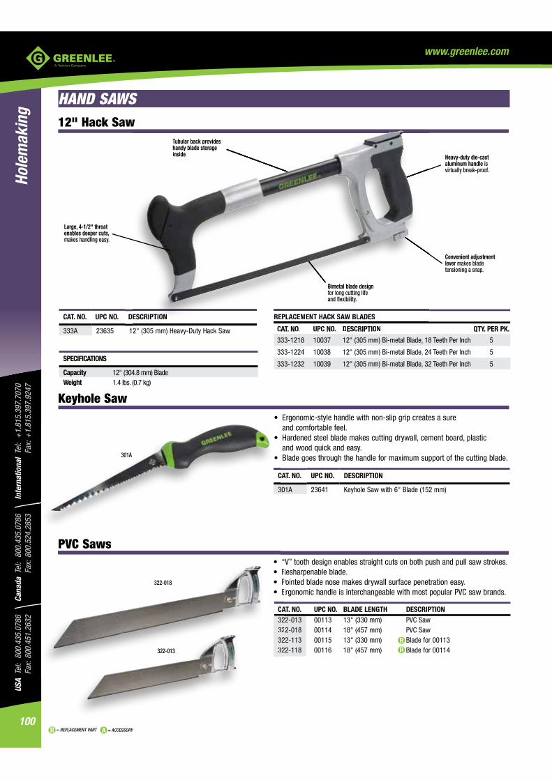
USA
Tel:
800
.435
.078
6
Fax:
800
.451
.263
2Ca
nada
Tel
: 80
0.43
5.07
86
Fax:
800
.524
.285
3In
tern
atio
nal
Tel:
+1.
815.
397.
7070
Fa
x: +
1.81
5.39
7.92
47
100
Hole
mak
ing
= REPLACEMENT PART = ACCESSORY
www.greenlee.com
HAND SAWS
Tubular back provides handy blade storage inside.
Large, 4-1/2" throat enables deeper cuts, makes handling easy.
Convenient adjustment lever makes blade tensioning a snap.
Heavy-duty die-cast aluminum handle is virtually break-proof.
12" Hack Saw
REPLACEMENT HACK SAW BLADES
CAT. NO. UPC NO. DESCRIPTION QTY. PER PK.
333-1218 10037 12" (305 mm) Bi-metal Blade, 18 Teeth Per Inch 5
333-1224 10038 12" (305 mm) Bi-metal Blade, 24 Teeth Per Inch 5
333-1232 10039 12" (305 mm) Bi-metal Blade, 32 Teeth Per Inch 5
CAT. NO. UPC NO. DESCRIPTION
333A 23635 12" (305 mm) Heavy-Duty Hack Saw
SPECIFICATIONS
Capacity 12" (304.8 mm) BladeWeight 1.4 lbs. (0.7 kg)
Keyhole Saw
and comfortable feel.
and wood quick and easy.
CAT. NO. UPC NO. BLADE LENGTH DESCRIPTION 322-013 00113 13" (330 mm) PVC Saw 322-018 00114 18" (457 mm) PVC Saw 322-113 00115 13" (330 mm) Blade for 00113 322-118 00116 18" (457 mm) Blade for 00114
CAT. NO. UPC NO. DESCRIPTION
301A 23641 Keyhole Saw with 6" Blade (152 mm)
PVC Saws
CA32323232322-013
322-018
Tubular back provides TThandy blade storageinside.
REPLACEMENT HACK SAWAA BLADES
CAT. NO. UPC NO. DESCRIPTION
ESCRIPTION
2" (305 mm) Heavy-Duty Hack Saw
C
3
PVC Saws
301A
Bimetal blade design for long cutting life and flexibility.

101
USA Tel: 800.435.0786
Fax: 800.451.2632Canada Tel: 800.435.0786
Fax: 800.524.2853International Tel: +
1.815.397.7070
Fax: +1.815.397.9247
Holemaking
= REPLACEMENT PART = ACCESSORY
www.greenlee.com
BAND SAWS
MOBILE BAND SAW BLADES
CAT. NO. UPC NO. DESCRIPTION TYPE APPLICATION TEETH PER INCH
399-14A 32336 1/2" x .025" x 93" Mobile Band Saw Blade1 Bi-metal Metal 10.14 399-18A 32337 1/2" x .025" x 93" Mobile Band Saw Blade1 Bi-metal Metal 18 399-24A 32338 1/2" x .025" x 93" Mobile Band Saw Blade1 Bi-metal Metal 24 389-1014 10044 1/2" x .020" x 44-7/8" Portable Band Saw Blade2 Bi-metal Metal 10/14 389-1418 10045 1/2" x .020" x 44-7/8" Portable Band Saw Blade2 Bi-metal Metal 14/18 389-24 10043 1/2" x .020" x 44-7/8" Portable Band Saw Blade2 Bi-metal Metal 241 Use with 1399 (31961) 2 Use with 530 (30276)
Heavy-Duty Band Saw
(23, 43, and 82 meters per minute).
SPECIFICATIONS
Capacity Rectangular 9-1/2" x 11" (241.3 x 279.4 mm) Round 9-1/2" Dia. or 8" Pipe (241.3 mm)
Throat Height 9-1/2" (241.3 mm) Throat Depth 6-1/4" (158.8 mm)
DimensionsPower Source 1399-120 VAC 1/2 Horsepower. 1399-22 - 220 VACWeight 346 lbs. (157 kg)Blade Size 1/2" x .025" x 93" (12.7 mm x 0.64 mm x 2362 mm)
CAT. NO. UPC NO. DESCRIPTION
1399 31961 9-1/2" x 11: Capacity Mobile Band Saw (241.3 x 279.4 mm)
1399-22 32364 9-1/2" x 11" Capacity Mobile Band Saw (241.3 x 279.4 mm) 220 VAC
32322 3232232237 32237
Band Saw BladesPerfect for your mobile or portable band saw, these top-quality, bi-metal blades feature high-speed steel teeth that can handle even tough metals like stainless steel with ease. Virtually unbreakable, too.
extra-tough alloy back for maximum hardness and heat resistance.

USA
Tel:
800
.435
.078
6
Fax:
800
.451
.263
2Ca
nada
Tel
: 80
0.43
5.07
86
Fax:
800
.524
.285
3In
tern
atio
nal
Tel:
+1.
815.
397.
7070
Fa
x: +
1.81
5.39
7.92
47
102
Hole
mak
ing
= REPLACEMENT PART = ACCESSORY
www.greenlee.com
ANCHORS AND FASTENERSAnchor and Fasterner Selection Guide
ANCHOR/FASTENER TYPE USE IN USE WITH MADE OF SIZE RANGE GENERAL INFORMATION
Concrete, brick, Machine Zinc alloy 1/4"- 20 to Single unit caulking anchor, can be set shallow (flush) or deep stone, block screw and lead 3/8"-16 in hole. Setting tool required (1 provided free in each box of or bolts anchors). For setting in hollow block or to set anchors all at the same depth, use Greenlee Screw anchor expander.
Concrete, brick, Machine Steel 1/4"-20 to Heavy-duty use in solid masonry where codes require all steel stone screw 3/8"-16 bolt anchors. Pre-assembled, internal expander plug. Can be or bolts installed flush with masonry surface or sub-set. Setting tool required (1 provided free in each box of anchors).
Concrete, block, No other Steel 1/4" x 1" to A safe, secure fastener that actually taps concrete and brick fastener 1/4" x 2-1/2" eliminates the need for concrete inserts with their alignment needed problems. Use with Greenlee masonry drill set tool.
Block, wallboard, No other Steel L3/16" x 3" to Available in round head and mushroom head. Fully-threaded plaster, tile fastener 3/8" x 4" machine screw with spring wing toggle head. needed
Concrete, block, No other Zinc and 1/4" x 1" to Fast, medium-duty. No hole spotting, removable. Use in brick fastener Steel 1/4" x 1-1/2" hollow or solid base applications. needed
brick screws plastic
Caulking
Drop
Masonry Screw
Toggle Bolts
Zinc Mushroom Head
Screw Anchor Expanders for Caulking Anchors
1. Drill hole of required size and put anchor screw on expander. Insert screw anchor into drilled hole.
2. Strike head of expander with hammer or mallet until anchor is held securely in wall. Unscrew expander.
EXPANSIVE USE WITH QTY. WEIGHT CAT. NO. UPC NO. BELT SIZE ANCHOR NO. PER BOX LB. kg
866
868 02669 1/4" – 20 84299 1 .4 .2
870 02671 3/8" – 16 84305 1 .6 .3
regardless of thickness.
CAT. NO. UPC NO. DESCRIPTION
4451AV 05191 Anchor Screw for 8664457AV 05197 Anchor Screw for 8684717AV 05300 Anchor Screw for 8701125GB 50423 Roll Pin 1/4" x 1-1/8"
Plastic Conical

103
USA Tel: 800.435.0786
Fax: 800.451.2632Canada Tel: 800.435.0786
Fax: 800.524.2853International Tel: +
1.815.397.7070
Fax: +1.815.397.9247
Holemaking
= REPLACEMENT PART = ACCESSORY
www.greenlee.com
Caulking Anchors
Drop Anchors
Greenlee setting tool required.
use Greenlee screw anchor expander.
4. Insert screw or bolt and tighten.
3. Using setting tool, caulk lead outer sleeve with sharp blows. Position fixture.
2. Insert anchor, conical end first, until flush with surface.
1. Drill hole in masonry.
TO SET ANCHOR FLUSH WITH SURFACES
1. Drill hole the same diameter as anchor being used.
2. Drive anchor flush with concrete.
3. Expand anchor with setting tool provided. Anchor is properly expanded when shoulder of setting tool is flush with top of anchor.
LEAD CAULKING ANCHORS AND SETTING TOOLS CAT./ THREAD REQ. HOLE SET QTY. WEIGHT WORKING LOAD PULLOUT UPC NO. SIZE DIA. MIN. DEPTH TOOL* PER BOX LBS. kg LBS. kg
84299 1/4"–20 1/2" 7/8" 84329 100 3.8 1.7 125 56.6
84305 3/8"–16 3/4" 1-1/4" 84335 50 7.1 3.2 312.5 141.6
*One Setting Tool included with each box of anchors.
Approvals: Conforms to the description in Federal Specification FFS-325, Group I, Type 1, Class 1. NOTE: Working load is one fourth the ultimate/maximum capacity. For critical or unusual applications, site testing is recommended.
TO SET ANCHOR BELOW SURFACES1. Drill hole deeper than anchor length. Thread bolt into anchor. Hammer anchor into hole
until bolt head is at desired height. Remove bolt and set anchor with setting tool.NOTE: The use of a 24 to 40 ounce hammer is recommended for expanding the anchor.
DROP ANCHORS AND SETTING TOOLS
CAT./ ANCHOR & BOLT MIN. THREAD SETTING QTY. WEIGHT UPC NO. HOLE DIA. THREAD SIZE DEPTH DEPTH TOOL* PER BOX LB. kg
84253 3/8" 1/4"–20 1-1/8" 1/2" 84273 100 3 1.4
84256 1/2" 3/8"–16 1-5/8" 5/8" 84276 50 7 3.2
*One Setting Tool included with each box of anchors.
SPECIFICATIONS
WORKING LOAD PULLOUT WORKING LOAD SHEAR CAT./UPC NO. LBS. kg LBS. kg
84253 1037 469.8 842.5 381.7
84256 1712.5 775.8 1518.7 688.9
Approvals: Conforms to the description in Federal Specification FFS-325, Group VIII, Type 1, for concrete expansion shield anchors.
NOTE: Working load is one fourth the ultimate/maximum capacity.
For critical or unusual applications, site testing is recommended.
ANCHOR FLUSH WITH SURFACES
1. Drill required diameter hole in material, to a minimum depth equal the overall anchor minus the thickness of the object to be fastened. Clean hole.
2. Insert anchor body through object to be fastened, and into the hole in base material.
3. Tap the nail until it is flush with the zinc anchor head.
CAT./ REQUIRED QTY WEIGHT UPC NO. SIZE HOLE SIZE PER BOX LBS. kg
84110 1/4" x 1" 1/4" 100 2 .9
84111 1/4" x 1-1/4" 1/4" 100 2.4 1.1
84112 1/4" x 1-1/2" 1/4" 100 2.6 1.2
NOTE: For critical or unusual applications, site testing is recommended.
Zinc Mushroom Head Drive Anchors

USA
Tel:
800
.435
.078
6
Fax:
800
.451
.263
2Ca
nada
Tel
: 80
0.43
5.07
86
Fax:
800
.524
.285
3In
tern
atio
nal
Tel:
+1.
815.
397.
7070
Fa
x: +
1.81
5.39
7.92
47
104
Hole
mak
ing
= REPLACEMENT PART = ACCESSORY
www.greenlee.com
1. Use set Tool with bit in drilling position to drill hole in surface.
2. Retract bit, insert masonry screw into socket head of tool and drive screw into hole.
MASONRY SCREW DRILL SET KIT MATERIAL CONCRETE 3000 PSI QTY.
CAT./ MIN. PULLOUT PER WT. UPC NO. DESCRIPTION EMBEDMENT LBS. BOX LBS. kg
84463 Masonry Screw Drill Set Kit Includes: 3/4" 1180 1 1.6 .7
84469 50 – 1/4" x 1" Masonry Screws
84472 50 – 1/4" x 1-1/4" Masonry Screws
84466 1– Masonry Screw Drill Set Tool with 84484 Bit
Small Jobs – Use special Greenlee masonry screw drill bit for holes. Screw can be installed with 5/16" wrench, nut driver or socket with ratchet.
Large Jobs – Use the special Greenlee Masonry Screw Drill Set Tool in kit with 3/8" or larger electric drill for drilling holes and screw installation.
MASONRY SCREW ANCHORS – EACH BOX OF 100 INCLUDES 1 BIT CAT./ MATERIAL CONCRETE 3000 PSI QTY. WT. UPC NO. SIZE MIN. EMBEDMENT PULLOUT LBS. PER BOX LBS. kg
84469 1/4" x 1" 3/4" 1180 100 1.2 .5
84472 1/4" x 1-1/4" 3/4" 1180 100 1.4 .6
84475 1/4" x 1-1/2" 1-1/4" 1800 100 1.6 .7
84478 1/4" x 2" 1-1/4" 1800 100 1.8 .8
84481 1/4" x 2-1/2" 1-1/4" 1800 100 2.1 1.0
INSTALLATION TOOLS QTY. CAT./ PER WT. UPC NO. DESCRIPTION BOX LBS. kg
84466 Masonry Screw Drill Set Tool with 84484 Bit 1 .4 .2
84484 3-1/2" Masonry Screw Drill Bit – for use 1 with 1" to 1-1/2" long screws
NOTE: For use in lightweight, hollow core concrete block, minimum embedment 1-3/8", pullout 715 lbs. Due to the variance in make-up of cement block, values will vary. It is suggested that the anchor be tested in specific material being used before installing fixtures.
Masonry Screw Anchors must be used with Greenlee masonry screw drill bits, numbers 84484 and 84487, which are a special size to insure secure thread engagement. Standard masonry bit size holes will not provide proper contact with screw threads and may cause masonry anchor screws to pull out.
Masonry Screw Anchors
for concrete inserts with their alignment problems.
onry Screw Anchors must be used with Greenlee masonry screw drill bits numbers
1. Drill hole full length of anchor or 1/8” deeper.
C
B
2. Tap anchor into hole flush with surface.
3. Insert screw through fixture into plastic plug and tighten.
ANCHORS ONLY
CAT./ USE WITH REQUIRED QTY. WEIGHT UPC NO. SCREW SIZES HOLE SIZE PER BOX LBS. kg
ANCHOR KITS CAT./ ANCHOR SCREW BIT WEIGHT UPC NO. SIZE SIZE TYPE SIZE LBS. kg
Plastic Conical Anchors

105
USA Tel: 800.435.0786
Fax: 800.451.2632Canada Tel: 800.435.0786
Fax: 800.524.2853International Tel: +
1.815.397.7070
Fax: +1.815.397.9247
Holemaking
= REPLACEMENT PART = ACCESSORY
www.greenlee.com
Round Head
Mushroom Head
1. Drill hole completely through wall. 2. Insert bolt through items to be fastened. Fold wings completely back, then push through hole until wings spring open.
3. Pull back to hold wings against inside wall while tightening with screw driver.
TOGGLE BOLTS AND SPRING WINGS
CAT./ TOGGLE BOLT REQUIRED QTY. WEIGHT UPC NO. SIZE HEAD HOLE SIZE PER BOX LBS. kg
84405 1/4" x 4" Round 11/16" 50 3.7 1.7 84409 3/8" x 4" Round 1" 25 4.3 1.9
84424 3/16" x 3" Mushroom 1/2" 50 1.9 .9 84425 3/16" x 4" Mushroom 1/2" 50 2.2 1.0
84428 1/4" x 3" Mushroom 11/16" 50 3.3 1.5 84429 1/4" x 4" Mushroom 11/16" 50 3.8 1.7
Toggle Bolts and Spring Wings
Round Head
Mushroom Head

USA
Tel:
800
.435
.078
6
Fax:
800
.451
.263
2Ca
nada
Tel
: 80
0.43
5.07
86
Fax:
800
.524
.285
3In
tern
atio
nal
Tel:
+1.
815.
397.
7070
Fa
x: +
1.81
5.39
7.92
47
106
Hole
mak
ing
= REPLACEMENT PART = ACCESSORY
www.greenlee.com
TAPCON® MASONRY FASTENERS – EACH BOX OF 100 INCLUDES 1 BIT
MAXIMUM FASTENER EMBEDMENT ATTACHMENT QTY.CAT. NO. UPC NO. SIZE TYPE MIN. MAX. THICKNESS PER BOX
LE 405 07405 1/4" x 1-1/4" A 1" 1-3/4" 1/4" 100
LE 415 07415 1/4" x 1-3/4" A 1" 1-3/4" 3/4" 100
LE 425 07425 1/4" x 2-1/4" A 1" 1-3/4" 1-1/4" 100
LE 435 07435 1/4" x 2-3/4" A 1" 1-3/4" 1-3/4" 100
LE 445 07445 1/4" x 3-1/4" A 1" 1-3/4" 2-1/4" 100
LE 455 07455 1/4" x 3-3/4" A 1" 1-3/4" 2-3/4" 100
LE 300 07300 3/16" x 1-1/4" A 1" 1-3/4" 1/4" 100
LE 310 07310 3/16" x 1-3/4" A 1" 1-3/4" 3/4" 100
LE 320 07320 3/16" x 2-1/4" A 1" 1-3/4" 1-1/4" 100
ASlotted Hex Washer Head
TAPCON® Masonry Fasteners and Drill Bits
ASlotted Hex Washer Head
® fasteners are protected against rust and corrosion by the exclusive Stalgard® finish.
® fasteners per minute. Simple two-step
® fasteners and the masonry material are mechanically linked for exceptionally strong pullout strength.
® fasteners can be removed and reinserted in the same hole. Great for repairs or adjustments.
PERCUSSION BITS
CAT./ HOLE DIA. SHANK WEIGHT UPC NO. INCH mm INCH mm LBS. g 84576 3/16 4.8 3/16 4.8 .03 14
84582 1/4 6.4 1/4 6.4 .05 23
84588 5/16 7.9 1/4 6.4 .06 27
84594 3/8 9.5 1/4 6.4 .08 36
84600 1/2 12.7 1/4 6.4 .12 54
FAST SPIRAL BITS
CAT./ HOLE DIA. SHANK WEIGHT UPC NO. INCH mm INCH mm LBS. g 84526 3/16 4.8 3/16 4.8 .03 14
84532 1/4 6.4 1/4 6.4 .05 23
84538 5/16 7.9 1/4 6.4 .06 27
84544 3/8 9.5 1/4 6.4 .08 36
84550 1/2 12.7 1/4 6.4 .12 54
Percussion
Fast Spiral
Masonry Bits
SPECIFICATIONS
Twist Length 2-1/2" (63 mm)Overall Length 4" (101 mm)
and fast spiral for use in conventional power drills.
MASONRY BITS

107
USA Tel: 800.435.0786
Fax: 800.451.2632Canada Tel: 800.435.0786
Fax: 800.524.2853International Tel: +
1.815.397.7070
Fax: +1.815.397.9247
Holemaking
= REPLACEMENT PART = ACCESSORY
www.greenlee.com
Multi-Purpose Installation Tool
High-Speed Installation Tool
CAT. NO. UPC NO. DESCRIPTION
LP 100 07100 Condrive 1000 kit consists of: Drill Adapter, Drill Sleeve Assembly, 5/16" Hex Driver-Magnetic, 1/4" Hex Socket for
1/8" Hex Key, Set Screw 1/4-28, Drive Sleeve Assembly for 5" & 6" Anchors
Speed Installation Tool
CAT. NO. UPC NO. DESCRIPTION
LP 200 07200 Condrive 2000 kit consists of: Tool Body/Drive Assembly, 5/16" Hex Socket for 1/4" Anchors, 1/4" Hex Socket for 3/16" Anchors, 1/8" Hex Key, 1/4" Hex Key, 5/16" Hex Key, Set Screw
of Tapcon fasteners.
® fasteners in lengths up to 2-3/4".
of Tapcon® masonry fasteners.
® anchors are easy to install... a simple, two-step operation

USA
Tel:
800
.435
.078
6
Fax:
800
.451
.263
2Ca
nada
Tel
: 80
0.43
5.07
86
Fax:
800
.524
.285
3In
tern
atio
nal
Tel:
+1.
815.
397.
7070
Fa
x: +
1.81
5.39
7.92
47
108
Hole
mak
ing
= REPLACEMENT PART = ACCESSORY
www.greenlee.com
NOTES