Embed Size (px)
Citation preview

1.8-1
D538- A/D
Profile Design ISO/VDMAAir Cylinder
Series CP95Ø32, Ø40, Ø50, Ø63, Ø80, Ø100
Profile design with enclosed tie-rods
Double acting Double acting Double rod type
Double acting Non-rotating rod type
CP95SDB32-150

1.8-2
Improved end of stroke cushioncapacityPiston rod lurching has been eliminated at the end of stroke positions by means of a floating seal mechanism.
Increased kinetic energy absorption
Compact and light design
Piston rod deflection reduced
Improved mounting accuracyHigh accuracy covers and tie rod nuts simplify the mounting process and also extend cylinder life.
Die casting of the covers has reduced the weight by 25%.
Deflection of the piston rod has been reduced by increasing the precision of the bushing and piston rod,and reducing the tolerances.
The absorption of kinetic energy hasbeen increased by nearly 30%, through increased cushion volume and the use of a new cushion seal.
Series CP95
Profile Design ISO/VDMA Air Cylinder

1.8-3
Ø32, Ø40, Ø50, Ø63, Ø80, Ø100
Easy end of stroke cushion valve adjustment
Space saving auto switch mounting
Appearance improved by enclosing the tie-rods
Dust accumulation can be prevented with optional fastener strips
Auto switch mounting grooves can be covered with resin fastener strips, which adhere tightly to the tube to preventthe entry and accumulation of dirt.
Since adjustment of the cushion valve is performed with a hexagon wrench key, even fine control can be easily accomplished. Furthermore, the cushion valve has been recessed so that it does not protrude from the cover.
Space is saved by setting switches completely into grooves provided on 4 surfaces.
Tie-rods are enclosed in an extruded aluminium profile barrel, which is integrated with both end covers to achieve a smooth and attractive appearance.
Port aperture
Key Page IndexPage
Available Specifications ..........................................................................................4
How to Order ........................................................................................................ 4-5
Technical Specifications .................................................................................. 6, 13
Dimensions (Cylinders).......................................................................... 9-12, 15-17
(Mounting Accessories) ...................................................................18
Auto Switches ...................................................................................................19-22
Guide Units ........................................................................................................23-25
Safety Instructions............................................................................................30-34
Main Index...............................................................................................................35

Type Model Bore Stroke end Rod specifications cushioning
as standard Standard type32 40 50 63 80 100 hard chromed W E R XB6
Standard CP95SB • • • • • • • • • • • •CP95SDB • • • • • • • • • • • –
Double CP95SB•W • • • • • • • • – • • •rod CP95SDB•W • • • • • • • • – • • –Non-rotating CP95KB • • • • • • • – • • • –rod CP95KDB • • • • • • • – • • • –D
oubl
e ac
ting
Upo
n re
ceip
t of
ord
er
W = double/through rodE = extended rodR = stainless rodXB6= heat resistant (to 150° C)
• available– not available
S Standard
K Non-rotating
Q Low friction
Nil Non-magneticD With built-in magnet
Nil With dry compressed air orlubricated (Standard)
CA Low friction in output direction
CB Low friction in inputdirection
XB6 Heat resistant to150° C (without magnet)*
Nil Hard chromed rod asstandard
W Double/through rod
E+.. Extended rod
R Stainless rod(not rquired for KB/KDB non-rotating model which already includes stainless rod)
Ø Bore[mm]3240506380100
CP95 S –
Piston rod
Stroke[mm](Standardstrokes – seepage 6)
Rod specifications
D 8032B
* The non-rotating rod is not available forXB6 specification.
Series CP95ISO/VDMA Air Cylinders
Specifications
How to order: Cylinders
Standard(Order themountingaccessoriesseparately – seepage 5)
Special specifications
How to order: AccessoriesPage
Mounting accessories Cylinder .............................................................5
Rod ....................................................................5
Switches and switch holders...........................................................................19-22
Snap-on switch groove covers .............................................................................22
Seal kits standard models................................................8
non-rotating models.........................................141.8-4

1.8-5
Mounting accessories, cylinders
Mounting accessories, rod
Ø bore
3240506380100
Ø bore
3240506380100
Ø bore
3240506380100
F5032F5040F5050F5063F5080F5100
See page 10 for dimensions
D5032D5040D5050D5063D5080D5100
See pages 10/11 for dimensions
Plain with ball jointC5032 CR5032C5040 CR5040C5050 CR5050C5063 CR6063C5080 CR5080C5100 CR5100See pages 10/11 for dimensionsNote: See page 11 for male rear clevis with swivel CR50
L5032L5040L5050L5063L5080L5100
See page 10 for dimensions
E5032E5040E5050E5063E5080E5100
See page 11 for dimensions
DS5032DS5040DS5050DS5063DS5080DS5100
See page 12 for dim.
ES5032ES5040ES5050ES5063ES5080ES5100
See page 12 for dim.
GKM 10-20GKM12-24GKM16-32GKM16-32GKM20-40GKM20-40
See page 18 for dimensions
KJ10 DKJ12 DKJ16 DKJ16 DKJ20DKJ20D
See page 18 for dimensions
JA30-10-125JA40-12-125JA50-16-150JA50-16-150JAH50-20-150JAH50-20-150
See page 18 for dimensions
F D C
L DS ES E
GKM KJ JA
Front/rear flange
Supplied with 4 screws
Female rear clevis(corresponds to E accessories)
Supplied with bolt, safety deviceand 4 screws
Male rear clevis
Supplied with 4 screws
Foot
Supplied with two pieces
Female rear clevis(for ES accessory)
Angled rear cleviswith ball joint
Angled rear clevis
Rod clevisDIN 71752
Piston rod ball jointDIN 648
Floating joint
Supplied with bolts and safetydevices
Series CP95How to order mounting accessories

1.8-6
• Conforms to VDMA 24 562 (parts 1 and 2),ISO 6431 and CETOP standards
• Combines lightweight profile barrel designwith enclosed tie rods for extra strength
• Unique seal system ensures efficientperformance and long life
• Fully adjustable cushioning at end of stroke
• Magnetic proximity sensing
• Superior cushioning performance andkinetic energy absorption
Bore [mm] 32 40 50 63 80 100Type Non-lube typeAction Double acting single rod Fluid Compressed air filtered to <10 µm,lubricated or non lubricated (dry air)Proof pressure 1.5MPa 15.3kgf/cm2Maximum operating pressure 1.0MPa 10.2kgf/cm2Minimum operating pressure 0.05MPa 0.5kgf/cm2
Piston force Up to 7500NPiston rod Hard chromed steel (25µm finish)Lubrication Not required (non-lube)Rod diameter [mm] 12 16 20 20 25 30Piston rod thread M10x1.25 M12x1.25 M16x1.5 M16x1.5 M20x1.5 M20x1.5Ports G1/8 G1/4 G1/4 G3/8 G3/8 G1/2Cushioning stroke [mm] 19 19 24 24 30 30Mounting position AnyStandard strokes 25, 50, 80, 100, 125, 160, 200, 250, 320, 400, 500, 600, 700, 800(DIN ISO 4393) [mm] Other stroke lengths in accordance with ISO497 R 10Stroke tolerance [mm] <250mm: + 1.0/-0mm, <1000mm: + 1.4/-0mm, <1500mm: + 1.8/-0mmWorking pressure [MPa] 0.05 - 1.0Fluid and ambient temperature [°C] -10°C to +60°C, -10°C to +70°C without magnetPiston speed [mm/s] 50 - 1000
Technical specifications
Ø Standard stroke Max.Bore stroke32 25, 50, 80, 100, 125, 160, 200, 250, 320, 400, 450, 500 70040 25, 50, 80, 100, 125, 160, 200, 250, 320, 400, 450, 500 80050 25, 50, 80, 100, 125, 160, 200, 250, 320, 400, 450, 500, 600 120063 25, 50, 80, 100, 125, 160, 200, 250, 320, 400, 450, 500, 600 120080 25, 50, 80, 100, 125, 160, 200, 250, 320, 400, 450, 500, 600, 700, 800 1400100 25, 50, 80, 100, 125, 160, 200, 250, 320, 400, 450, 500, 600, 700, 800 1500
Standard strokes
ISO/VDMA Air Cylinder
Series CP95 VDMADouble acting with end of stroke cushioning Ø32 - Ø100
[mm]
Note: Intermediate strokes are also available
1.8-7
Series CP95
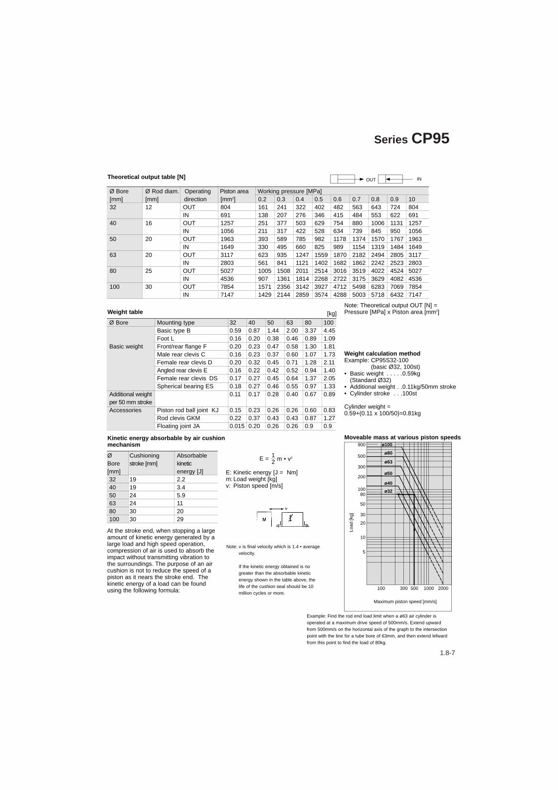
Ø Bore Ø Rod diam. Operating Piston area Working pressure [MPa][mm] [mm] direction [mm2] 0.2 0.3 0.4 0.5 0.6 0.7 0.8 0.9 1032 12 OUT 804 161 241 322 402 482 563 643 724 804
IN 691 138 207 276 346 415 484 553 622 69140 16 OUT 1257 251 377 503 629 754 880 1006 1131 1257
IN 1056 211 317 422 528 634 739 845 950 105650 20 OUT 1963 393 589 785 982 1178 1374 1570 1767 1963
IN 1649 330 495 660 825 989 1154 1319 1484 164963 20 OUT 3117 623 935 1247 1559 1870 2182 2494 2805 3117
IN 2803 561 841 1121 1402 1682 1862 2242 2523 280380 25 OUT 5027 1005 1508 2011 2514 3016 3519 4022 4524 5027
IN 4536 907 1361 1814 2268 2722 3175 3629 4082 4536100 30 OUT 7854 1571 2356 3142 3927 4712 5498 6283 7069 7854
IN 7147 1429 2144 2859 3574 4288 5003 5718 6432 7147
Theoretical output table [N]
Ø Bore Mounting type 32 40 50 63 80 100 Basic type B 0.59 0.87 1.44 2.00 3.37 4.45Foot L 0.16 0.20 0.38 0.46 0.89 1.09
Basic weight Front/rear flange F 0.20 0.23 0.47 0.58 1.30 1.81Male rear clevis C 0.16 0.23 0.37 0.60 1.07 1.73Female rear clevis D 0.20 0.32 0.45 0.71 1.28 2.11Angled rear clevis E 0.16 0.22 0.42 0.52 0.94 1.40Female rear clevis DS 0.17 0.27 0.45 0.64 1.37 2.05Spherical bearing ES 0.18 0.27 0.46 0.55 0.97 1.33
Additional weight 0.11 0.17 0.28 0.40 0.67 0.89per 50 mm strokeAccessories Piston rod ball joint KJ 0.15 0.23 0.26 0.26 0.60 0.83
Rod clevis GKM 0.22 0.37 0.43 0.43 0.87 1.27Floating joint JA 0.015 0.20 0.26 0.26 0.9 0.9
Weight table
Weight calculation methodExample: CP95S32-100
(basic Ø32, 100st)• Basic weight . . . . .0.59kg
(Standard Ø32)• Additional weight . .0.11kg/50mm stroke• Cylinder stroke . . .100st
Cylinder weight = 0.59+(0.11 x 100/50)=0.81kg
Note: Theoretical output OUT [N] =Pressure [MPa] x Piston area [mm2]
Ø Cushioning AbsorbableBore stroke [mm] kinetic[mm] energy [J]32 19 2.240 19 3.450 24 5.963 24 1180 30 20100 30 29
Kinetic energy absorbable by air cushion mechanism
At the stroke end, when stopping a largeamount of kinetic energy generated by alarge load and high speed operation,compression of air is used to absorb theimpact without transmitting vibration tothe surroundings. The purpose of an aircushion is not to reduce the speed of apiston as it nears the stroke end. Thekinetic energy of a load can be foundusing the following formula:
Example: Find the rod end load limit when a ø63 air cylinder isoperated at a maximum drive speed of 500mm/s. Extend upwardfrom 500mm/s on the horizontal axis of the graph to the intersectionpoint with the line for a tube bore of 63mm, and then extend lefwardfrom this point to find the load of 80kg.
Moveable mass at various piston speeds
E: Kinetic energy [J = Nm]m: Load weight [kg]v: Piston speed [m/s]
12E = m • v2
100 300 1000 2000500
900
500
300
200
10080
50
30
20
10
ø32
ø40
ø100
ø80
ø63
ø50
5
Maximum piston speed [mm/s]
Load
[kg]
[kg]
OUT IN
Note: v is final velocity which is 1.4 • averagevelocity.
If the kinetic energy obtained is nogreater than the absorbable kineticenergy shown in the table above, thelife of the cushion seal should be 10million cycles or more.

1.8-8
Series CP95
No. Description Material Head cover Die-cast aluminum End cover Die-cast aluminum Cylinder tube Die-cast aluminum Piston rod Hard chromed steel C45 Piston Die-cast aluminum Cushion ring Brass Tie rod Steel, zinc chromate plated Tie rod nut Steel, zinc chromate plated Rod end nut Steel, zinc chromate plated Snap ring Steel nickel plated Bushing Lead-bronze casting Cushion valve Steel, zinc chromate plated Cushion seal Elastomer Wear ring Antifriction material Piston seal NBR Rod seal NBR Cylinder tube gasket NBR Cushioning valve seal NBR Piston/rod gasket NBR Magnet ring
Replacement parts: Seal kitsØ32 includes order No. from to , Ø40 - Ø100 includes from to
Ø Order No.32 CS95-3240 CS95-4050 CS95-5063 CS95-6380 CS95-80100 CS95-100
Parts list
A
A' Sectional view A-A'
Construction
Ø L1 L2 FB1 allowable32 62.5 34.5 + st 80 N40 74.0 39.0 + st 125 N50 76.0 44.5 + st 195 N63 91.0 44.5 + st 310 N80 93.0 53.0 + st 500 N100 104.0 57.5 + st 785 N
L2L1
FB1 = WS (1+ ) ≤ FB allowable
Maximum allowable radial loads
Stroke
e.g. 63mm bore, 100mm stroke, Ws = 20N
Ws = (2kgs) 20N
144.591
FB1 = 20 (1+ ) = 51.76N
FB1 = 51.76N ≤ 310N (from table)
Therefore, side load is allowable

1.8-9
Ø Bore AM ØB ØD EE PL RT I12 KK SW G BG I8
32 22 30 12 G1/8 13 M6 6 M10x1.25 10 27 16 9440 24 35 16 G1/4 14 M6 6.5 M12x1.25 13 27 16 10550 32 40 20 G1/4 15.5 M8 8 M16x1.5 16 31.5 16 10663 32 45 20 G3/8 16.5 M8 8 M16x1.5 16 31.5 16 12180 40 45 25 G3/8 19 M10 10 M20x1.5 21 38 16 128100 40 55 30 G1/2 19 M10 10 M20x1.5 21 38 16 138
VD VA WA WB WH ZZ ZY E R I2 I9
4 4 4 6.5 26 146 190 46 32.5 15 44 4 4 9 30 163 213 52 38 17 46 4 5 10.5 37 179 244 65 46.5 24 56 4 9 12 37 194 259 75 56.5 24 58 4 11.5 14 46 218 300 95 72 30 58 4 17 15 51 233 320 114 89 32 5
CP95SBØ-stroke
CP95SBØ-stroke W
Dimensions - standard specifications [mm]
STROKE
STROKE
STROKE
STROKE
Stroke endcushioning
STROKE
ISO/VDMA Air Cylinders Series CP95

1.8-10
Series CP95
Mounting type L
Mounting type F
Mounting type C Mounting type D
Rear mounting
Front mounting
Dimensions – mounting accessories L, F, C and D [mm]
Ø Bore
STROKE
STROKE
STROKE
STROKE

1.8-11
Ø Bore E1 EW TG1FL l1 L I2 Ød1 CD MR d2 R1 E2 UB CB
32 45 26 32.5 22 5 12 5.5 30 10 9.5 6.6 6.5 48 45 2640 51 28 38 25 5 15 5.5 35 12 12 6.6 6.5 56 52 2850 64 32 46.5 27 5 15 6.5 40 12 12 9 8.5 64 60 3263 74 40 56.5 32 5 20 6.5 45 16 16 9 8.5 75 70 4080 94 50 72 36 5 20 10 45 16 16 11 11 95 90 50100 113 60 89 41 5 25 10 55 20 20 11 12 115 110 60
Ø Bore Ød2 ØCK ØS5 K1 K2 l3 G1 l1 G2 EM G3 CA H6 R1
32 11 10 6.6 38 51 10 21 7 18 26 31 32 8 1040 11 12 6.6 41 54 10 24 9 22 28 35 36 10 1150 15 12 9 50 65 12 33 11 30 32 45 45 12 1263 15 16 9 52 67 14 37 11 35 40 50 50 12 1580 18 16 11 66 86 18 47 12.5 40 50 60 63 14 15100 18 20 11 76 96 20 55 13.5 50 60 70 71 15 19
Mounting type E
Mounting type C Mounting type D
Dimensions – mounting accessories C, D, E and CR [mm]
Mounting type CR Rear clevis with ball joint
ISO/VDMA Air Cylinders Series CP95
Ø A B C D EN ER ØF G E L M N P H R(mm) ±0.2 maxi JS15H7 -0.1 maxi H11 H13 H13 ±0.5 ±0.5 ±0.5
32 32.5 10.5 22 10 14 15 30 10 6.6 45 10.5 5.5 5 – –40 38 12 25 12 16 18 35 10 6.6 55 11 5.5 5 – –50 46.5 15 27 16 21 20 40 10 9 65 15 6.5 5 51 1963 56.5 15 32 16 21 23 45 12 9 75 15 6.5 5 – –80 72 18 36 20 25 27 45 14 11 95 18 10 5 – –100 89 18 41 20 25 30 55 16 11 115 18 10 5 – –

1.8-12
Mounting type DS
Mounting type ES
Ø Bore E B1 B2 B3 TG1 T L1 L3 I1 I2 FL H Ød1 Ød2 Ød3 CN XD
32 45 14 34 3.3 32.5 3 11.5 41 5 5.5 22 10 30 10.5 6.6 10 14240 55 16 40 4.3 38 4 12 48 5 5.5 25 10 35 11 6.6 12 16050 65 21 45 4.3 46.5 4 14 54 5 6.5 27 10 40 15 9 16 17063 75 21 51 4.3 56.5 4 14 60 5 6.5 32 12 45 15 9 16 19080 95 25 65 4.3 72 4 16 75 5 10 36 16 45 18 11 20 210100 115 25 75 6.3 89 4 16 85 5 10 41 16 55 18 11 20 230
Ø Bore Ød3 ØCN ØS5 K1 K2 I2 G1 G2 G3 EN EU CH H6 ER
32 11 10 6.6 38 51 8.5 21 18 31 14 10.5 32 10 1540 11 12 6.6 41 54 8.5 24 22 35 16 12 36 10 1850 15 16 9 50 65 10.5 33 30 45 21 15 45 12 2063 15 16 9 52 67 10.5 37 35 50 21 15 50 12 2380 18 20 11 66 86 11.5 47 40 60 25 18 63 14 27100 18 20 11 76 96 12.5 55 50 70 25 18 71 15 30
Dimensions – mounting accessories DS and ES [mm]
Series CP95
Piston rod ball joint toDIN 648K
STROKE

1.8-13
Bore [mm] 32 40 50 63 80 100 Type Non-lube type air cylinder Action Double acting single rodFluid Compressed air filtered to < 10 µm, lubricated or non lubricated (dry air)Proof pressure 1.5MPa 15.3kgf/cm2Maximum operating pressure 1.0MPa 10.2kgf/cm2Minimum operating pressure 0.05MPa 0.5kgf/cm2Piston force Up to 7500NRod width across flats [mm] 1) 12.2 14.2 19 19 23 27Piston rod thread M10 x 1.25 M12 x 1.25 M16 x 1.5 M16 x 1.5 M20 x 1.5 M20 x 1.5Ports G1/8 G1/4 G1/4 G3/8 G3/8 G1/2Cushioning stroke [mm] 19 19 24 24 30 30Mounting position AnyStandard strokes [mm] 25, 50, 80, 100, 125, 160, 200, 250, 320, 400, 500, 600, 700, 800 (DIN ISO 4393) [mm] Other stroke lengths in accordance with ISO 497 R 10Stroke tolerance [mm] <250mm: +1.0/-0mm, <1000mm: +1.4/-0mmWorking pressure [MPa] 0.05 - 1.0Fluid and ambient temperature [°C] -10°C to +60°C built-in magnet / -10°C to +70°C without magnetPiston speed [mm/s] 50 - 1000Rod non-rotating accuracy ± 0.5° ± 0.5° ± 0.5° ± 0.5° ± 0.3° ± 0.3°Allowable maximum stroke [mm] 2) 700 800 1200 1400 1500Allowable Torque [Nm] 0.25 0.45 0.64 0.64 0.79 0.93Rod material Stainless steel
Technical specifications
2) For longer stroke lengths please contact SMC.
ISO/VDMA Air Cylinders
Series CP95KDouble acting with end of stroke cushioning and non-rotating rod Ø32 - Ø100
1)
Width across flats
• Conforms to VDMA 24 562 (parts 1 and 2),ISO 6431 and CETOP standards
• Combines lightweight profile barrel designwith enclosed tie rods for extra strength
• Unique seal system ensures efficientperformance and long life
• Fully adjustable cushioning at end of stroke
• Magnetic proximity sensing
• Superior cushioning performance andkinetic energy absorption

1.8-14
Series CP95K
Replacement parts: Seal kitsØ32 includes the order No. from 13 to 17,Ø40-Ø100 includes from 12 to 18.
Ø Bore Order No.32 CK95-3240 CK95-4050 CK95-5063 CK95-6380 CK95-80100 CK95-100
Parts list
Construction
No. Description Material Head cover Die-cast aluminum End cover Die-cast aluminum Cylinder tube Die-cast aluminum Piston rod Stainless Steel Piston Die-cast aluminum Cushion ring Brass Tie rod Steel, zinc chromate plated Tie rod nut Steel, zinc chromate plated Rod end nut Steel, zinc chromate plated Snap ring Steel nickel plated Bushing Lead-bronze casting Cushion valve Steel, zinc chromate plated Cushion seal Elastomer Wear ring Antifriction material Piston seal NBR Rod seal NBR Cylinder tube gasket NBR Cushioning valve seal NBR Piston/rod gasket NBR Magnet ring

1.8-15
CP95KBØ-Stroke
CP95KBØ-Stroke W
Ø Bore AM ØB ØD EE PL RT I12 KK SW SW1 G BG I8
32 22 30 12 G1/8 13 M6 6 M10x1.25 10 12.2 27 16 94
40 24 35 16 G1/4 14 M6 6.5 M12x1.25 13 14.2 27 16 105
50 32 40 20 G1/4 15.5 M8 8 M16x1.5 16 19 31.5 16 106
63 32 45 20 G3/8 16.5 M8 8 M16x1.5 16 19 31.5 16 121
80 40 45 25 G3/8 19 M10 10 M20x1.5 21 23 38 16 128
100 40 55 30 G1/2 19 M10 10 M20x1.5 21 27 38 16 138
VD VA WA WB WH ZZ ZY E R I2 Ig
4 4 4 6.5 26 146 190 46 32.5 15 4
4 4 4 9 30 163 213 52 38 17 4
6 4 5 10.5 37 179 244 65 46.5 24 5
6 4 9 12 37 194 259 75 56.5 24 5
8 4 11.5 14 46 218 300 95 72 30 5
8 4 17 15 51 233 320 114 89 32 5
Dimensions – non-rotating rod specification [mm]
STROKE
STROKE
Stroke endcushioning
STROKE
STROKE
STROKE
ISO/VDMA Air Cylinders Series CP95K
1.8-16
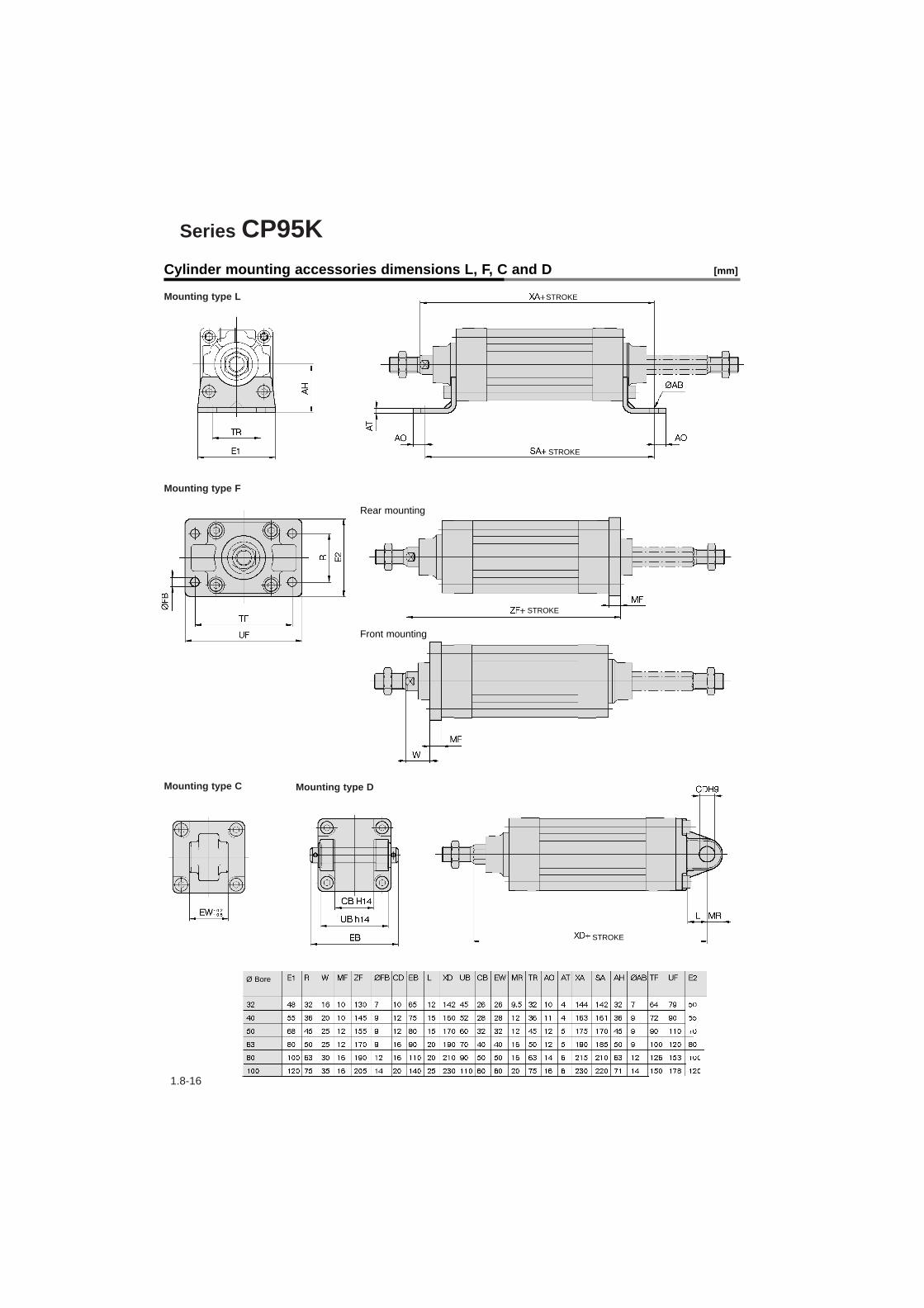
Series CP95K
Mounting type L
Mounting type F
Mounting type C Mounting type D
Rear mounting
Front mounting
Cylinder mounting accessories dimensions L, F, C and D [mm]
Ø Bore
STROKE
STROKE
STROKE
STROKE
1.8-17
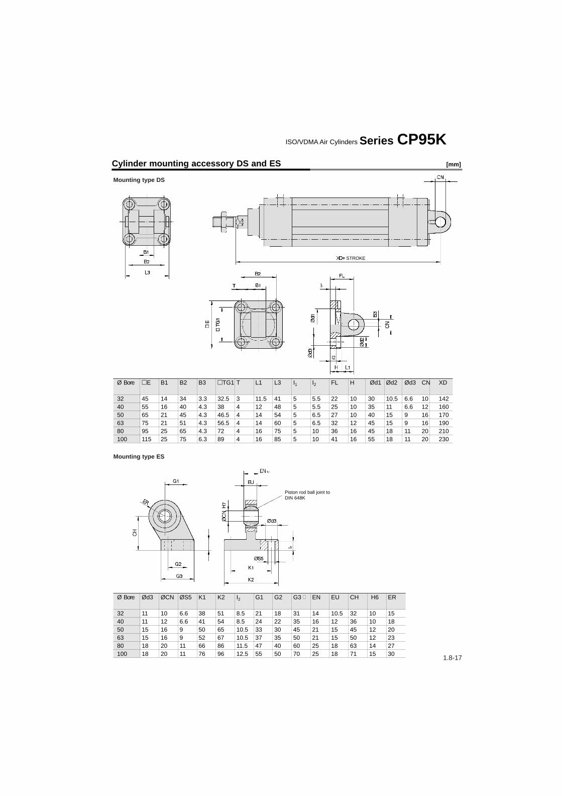
Mounting type DS
Mounting type ES
Ø Bore E B1 B2 B3 TG1 T L1 L3 I1 I2 FL H Ød1 Ød2 Ød3 CN XD
32 45 14 34 3.3 32.5 3 11.5 41 5 5.5 22 10 30 10.5 6.6 10 14240 55 16 40 4.3 38 4 12 48 5 5.5 25 10 35 11 6.6 12 16050 65 21 45 4.3 46.5 4 14 54 5 6.5 27 10 40 15 9 16 17063 75 21 51 4.3 56.5 4 14 60 5 6.5 32 12 45 15 9 16 19080 95 25 65 4.3 72 4 16 75 5 10 36 16 45 18 11 20 210100 115 25 75 6.3 89 4 16 85 5 10 41 16 55 18 11 20 230
Ø Bore Ød3 ØCN ØS5 K1 K2 I2 G1 G2 G3 EN EU CH H6 ER
32 11 10 6.6 38 51 8.5 21 18 31 14 10.5 32 10 1540 11 12 6.6 41 54 8.5 24 22 35 16 12 36 10 1850 15 16 9 50 65 10.5 33 30 45 21 15 45 12 2063 15 16 9 52 67 10.5 37 35 50 21 15 50 12 2380 18 20 11 66 86 11.5 47 40 60 25 18 63 14 27100 18 20 11 76 96 12.5 55 50 70 25 18 71 15 30
Cylinder mounting accessory DS and ES [mm]
Piston rod ball joint to DIN 648K
STROKE
ISO/VDMA Air Cylinders Series CP95K

1.8-18
Piston rod ball joint KJ (DIN 648)Zinc chromate plated steel
Rod clevis GKM (DIN 71752), supplied with bolt and safety deviceChromed steel
Floating joint JACarbon tool steel
Piston Rod mounting accessory dimensions [mm]
Series CP95
Ø Bore M Order No. A B C ØD E F G H P U Load [kN] Weight [g] Angle32 M10x1.25 JA30-10-125 49.5 19.5 – 24 5 8 8 17 9 0.5 2.5 7040 M12x1.25 JA40-12-125 60 20 – 31 6 11 11 22 13 0.75 4.4 160 ±5°50/63 M16x1.5 JA50-16-150 71.5 22 – 41 7.5 14 13.5 27 15 1.0 11 30080/100 M20x1.5 JAH50-20-150 101 28 31 59.5 11.5 24 16 32 18 2.0 18 1080
Ø Bore e Order No. b d Øf l1 c a32 M10x1.25 GKM10-20 10 40 10 52 20 2040 M12x1.25 GKM12-24 12 48 12 62 24 2450/63 M16x1.5 GKM16-32 16 64 16 83 32 3280/100 M20x1.5 GKM20-40 20 80 20 105 40 40
Ø Bore d3 Order No. d1 h d6 b3 b1 l d7 α l3 sw32 M10x1.25 KJ10D 10 43 28 10.5 14 20 19 13° 14 1740 M12x1.25 KJ12D 12 50 32 12 16 22 22 13° 16 1950/63 M16x1.5 KJ16D 16 64 42 15 21 28 27 15° 26 3280/100 M20x1.5 KJ20D 20 77 50 18 25 33 34 15° 26 32
Bore size(mm)Order No.
3240
50, 6380100
NT-03NT-04NT-05NT-08NT-10
d
M10 x 1.25M14 x 1.5 M18 x 1.5 M22 x 1.5 M26 x 1.5
H
68
111316
B
1722273241
C
19.625.431.237.047.3
D
16.521263139
Rod end nut(standard equipment)
B
C
d
D
H
30°
1.8-19
Dimensions [mm]
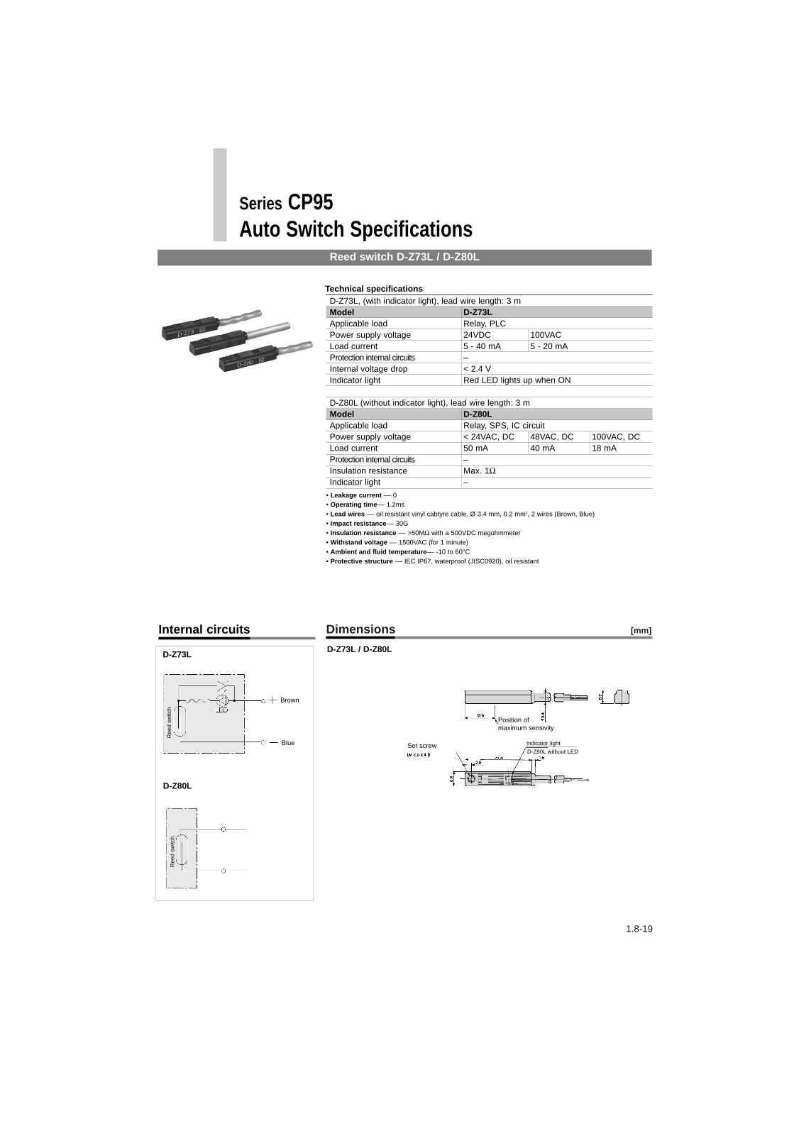
D-Z73L, (with indicator light), lead wire length: 3 mModel D-Z73LApplicable load Relay, PLCPower supply voltage 24VDC 100VACLoad current 5 - 40 mA 5 - 20 mAProtection internal circuits –Internal voltage drop < 2.4 VIndicator light Red LED lights up when ON
D-Z80L (without indicator light), lead wire length: 3 mModel D-Z80LApplicable load Relay, SPS, IC circuitPower supply voltage < 24VAC, DC 48VAC, DC 100VAC, DCLoad current 50 mA 40 mA 18 mAProtection internal circuits –Insulation resistance Max. 1ΩIndicator light –
Technical specifications
• Leakage current –– 0• Operating time–– 1.2ms• Lead wires –– oil resistant vinyl cabtyre cable, Ø 3.4 mm, 0.2 mm2, 2 wires (Brown, Blue)• Impact resistance–– 30G• Insulation resistance –– >50MΩ with a 500VDC megohmmeter• Withstand voltage –– 1500VAC (for 1 minute)• Ambient and fluid temperature–– -10 to 60°C• Protective structure –– IEC IP67, waterproof (JISC0920), oil resistant
D-Z73L
D-Z80L
Reed switch D-Z73L / D-Z80L
Series CP95Auto Switch Specifications
Internal circuits
D-Z73L / D-Z80L
Brown
Blue
Position of maximum sensivity
Set screw Indicator light
D-Z80L without LED
Ree
d sw
itch
Ree
d sw
itch

1.8-20
D-Y7PL (with indicator light), lead wire length 3 mModel D-Y7PL D-Y7PVLWiring system 3 wires, axial 3 wires, verticalOutput system PNPApplicable load IC circuit, relay, PLCPower supply voltage 4.5VDC - 28 VDCCurrent consumption OFF: < 1 mA, ON: < 15 mALoad current < 80 mAInternal voltage drop < 0.8VLeakage current 0.1 mAIndicator light Red LED lights up when ON
Technical specifications
• Operating time –– 1.2ms• Lead wires–– oil resistant vinyl cabtyre cable, Ø 3.4 mm, 0.2 mm2, 3wires (Brown, Black, Blue)• Impact resistance –– 30G• Insulation resistance –– >50MΩ with a 500VDC megohmmeter• Withstand voltage –– 1500VAC (for 1 minute)• Ambient temperature –– -10 to 60°C• Protective structure –– IEC IP67, waterproof (JISC0920), oil resistant
D-Y7PL / D-Y7PVLD-Y7PL
D-Y7PVL
Internal circuits Dimensions [mm]
Solid state D-Y7, 3 wires
Series CP95Auto Switch Specifications
Brown
Blue
Black(Output)
Position ofmaximum sensivity
Indicator light
Mounting screw
Mounting screw
Indicator light
Operating rangePosition of medium sensivity
Mai
n sw
itch
circ
uit
1.8-21
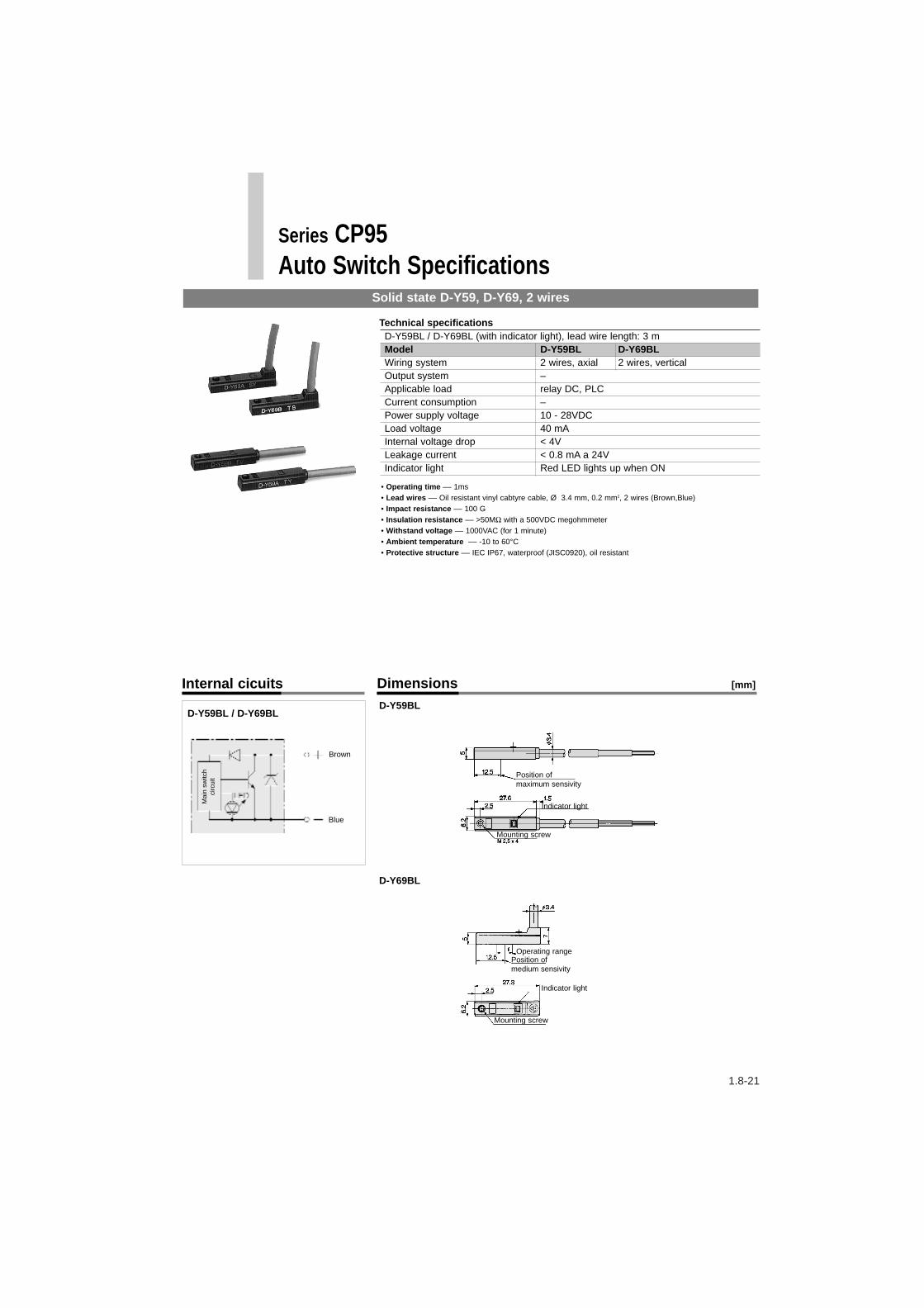
D-Y59BL / D-Y69BL (with indicator light), lead wire length: 3 mModel D-Y59BL D-Y69BLWiring system 2 wires, axial 2 wires, verticalOutput system –Applicable load relay DC, PLCCurrent consumption –Power supply voltage 10 - 28VDCLoad voltage 40 mAInternal voltage drop < 4VLeakage current < 0.8 mA a 24V Indicator light Red LED lights up when ON
Technical specifications
• Operating time –– 1ms• Lead wires –– Oil resistant vinyl cabtyre cable, Ø 3.4 mm, 0.2 mm2, 2 wires (Brown,Blue)• Impact resistance –– 100 G• Insulation resistance –– >50MΩ with a 500VDC megohmmeter• Withstand voltage –– 1000VAC (for 1 minute)• Ambient temperature –– -10 to 60°C• Protective structure –– IEC IP67, waterproof (JISC0920), oil resistant
D-Y59BL
D-Y69BL
D-Y59BL / D-Y69BL
Internal cicuits Dimensions [mm]
Solid state D-Y59, D-Y69, 2 wires
Series CP95Auto Switch Specifications
Brown
Blue
Mounting screw
Indicator light
Operating rangePosition of medium sensivity
Mounting screw
Indicator light
Position of maximum sensivity
Mai
n sw
itch
circ
uit

1.8-22
Auto switch type Model Amount* of Ø32 Ø40 Ø50 Ø63 Ø80 Ø100switches
Reed D-Z73L 2 pcs. 25 15D-Z80L 1 pcs.
Solid D-Y59BL 2 pcs. 25 15state D-Y69BL 1 pcs.
D-Y7PL
Bore D-Z73L, D-Z80L, D-Y7PL(mm) D-Y59BL, D-Y69BL
A B32 14 140 25 150 16 263 31 280 21.5 5.5100 31.5 5.5
Series CP95Auto switch mounting [mm]
Minimum strokes for auto switches
Recommended mounting position for stroke ends [mm]
How to order: Auto Switches, holders and Groove Covers
Order No. Ø Auto Switch holder
switch32 D-Z73L BMP1-03240 D-Z80L50 D-Y7PL63 D-Y59BL80 D-Y69BL100
Ø Order No. Cylinder lengthwithout stroke
32 CP95-AL 41.5 mm40 52.5 mm50 44.5 mm63 59.5 mm80 53.5 mm100 63.5 mm
Groove cover of square tube
Order example: Groove cover for CP95SB63-16059.5 mm + 160 mm = 239.5 x 8 grooves = 1916 mm[Cylinder length without stroke] [Stroke] [8 grooves in the square tube]
Length to order: 1916 mm corresponds to a groove cover of 2 m for each cylinderOrder No.: CP95-AL x length in metres
Groove covers are available inprogressive rates of 1 metre. Please,indicate round figures when ordering.
Auto switch holder band
*Auto switches are mounted on the same side but in different grooves of the cylinder.
Write the required length of the groove cover in the box.
Mounting of Auto Switches
Correct Incorrect
Flat head watchmakers screw driver
Switch holder
Switch mounting screw (M2.5 x 4l)Accessory
ø5 to ø6
1N·m: approx. 10.2kgf⋅cm
Note) When tightening the auto switch mounting screw, use a watchmakers screw driver with a handle about 5 to 6mm in diameter.Tighten to a torque of approximately 0.05 to 0.1Nm (0.51 to 1.02kgf·cm).As a rule, it is turned about 90° past the point at which tightening can be felt.
When attaching an auto switch, first take a switch holder between your fingers and press it into a switch mounting groove. When doing this, confirm that it is set in the correct mounting orientation, or reattach if necessary. Next, insert an auto switch into the groove and slide it until it is positioned under the switch holder. After establishing the mounting position, use a watchmakers flat head screw driver to tighten the switch mounting screw which is included.
BMP1-032
Switch holder: BMP1-032

1.8-23
Series CP95Guide Units
• Ball bush and Slide Bearing options.
• High resistance to side load.
• High non-rotating accuracy.
• Direct Mounting facility.
• Stroke adjusting unit option. Ø32~Ø63
32 Ø3240 Ø4050 Ø5063 Ø6380 Ø80100 Ø100
GUM (F) –
Bore Size (mm)
How to order: Guide Units
255080100125160200250320400500
Stroke(mm) 32 Ø32
40 Ø4050 Ø5063 Ø6380 Ø80100 Ø100
GUL (F) –
Bore Size (mm)
255080100125160200250320400500
Stroke(mm)
Slide bearing type Bush bearing type
Cylinder
Bore Size Part Number
(mm) Stroke adjusting unit Shock absorber
32 SFY(F)133 RBC1412
40 SFY(F)134 RBC2015
50 SFY(F)135 RBC2015
63 SFY(F)136 RBC2015
How to order: Stroke Adjusting Unit* and Shock Absorber*
* Order separately

1.8-24
Series CP95
Dimensions GUM/GUL Guide Unit [mm]
Diameter A B C D1 D2 D3 E2 E3 E4 F L0 L1 L2 L3L L4 L5 L6 L7 L8 L9 M P S32 12 12 74 m6 6.6 11 33 78 61 4 45 92 50 97 147 120 64 20 60 102 6.5 12 M10x1.2540 16 15 87 M6 6.6 11 38 84 69 18 55 112 58 116 167 125 81 25 63 127 6 12 M12x1.2550 20 19 104 M8 9 15 47 100 85 24 68 134 70 137 195 140 94 25 70 134 9 16 M16x1.563 20 19 119 M8 9 15 57 105 100 20 80 148 85 152 195 160 94 25 75 145 9 16 M16x1.580 25 22 148 M10 11 18 72 130 130 25 100 180 105 189 241 195 114 30 89 157 11 20 M20x1.5100 25 22 173 M10 11 18 89 150 150 30 120 206 130 213 241 205 120 30 90 172 11 20 M20x1.5
Dimensions Stroke Adjusting Unit [mm]
Diameter Model A B D1 D2 E F G H J Min. add on strokeø32 SFY(F)133 35.5 15 M14x1.5 M8 51 95 78 17 53 51ø40 SFY(F)134 45 20 M20x1.5 M10 59 114 87 25 62 65ø50 SFY(F)135 45 25 M20x1.5 M10 72 135 98 28 68 70ø63 SFY(F)136 45 25 M25x1.5 M10 86 150 118 28 88 70
A minimum length will have to be added on for stroke adjusting unit. (mm)

1.8-25
Series CP95
Permissable Rotary Torque Plate (Nm) Allowable Load [daN]
Diameter Series Stroke(mm) 50 100 200 300 400 50032 GUM 11.4 7.5 4.0 2.7 2.2 -32 GUL 6.0 4.5 3.1 2.3 1.8 -40 GUM 21.7 16.6 9.9 7.0 5.1 3.640 GUL 11.1 8.4 5.7 4.35 3.48 2.950 GUM 37.4 28.7 15.3 11.5 9.1 6.750 GUL 18.5 14.5 10.0 7.6 5.9 4.763 GUM 47.6 36.1 20.1 13.9 10.7 8.063 GUL 22.6 17.9 12.7 9.8 8.0 6.480 GUM 81.4 65.1 42.1 28.8 21.8 17.380 GUL 45.5 37.2 27.3 21.6 17.8 15.1100 GUM 95.1 76.1 49.3 33.7 25.5 20.3100 GUL 53.1 43.5 32.0 25.2 20.8 17.7
Deflection (For max. allowable load) [mm]
Diameter Series Stroke(mm) 50 100 200 300 400 50032 GUM 0.09 0.32 1.06 2.10 3.90 -32 GUL 0.05 0.20 0.80 1.80 3.30 -40 GUM 0.05 0.19 0.70 1.50 2.40 3.3040 GUL 0.02 0.10 0.40 0.90 1.60 2.6050 GUM 0.03 0.12 0.38 0.90 1.50 2.1050 GUL 0.015 0.06 0.25 0.57 1.00 1.5063 GUM 0.04 0.15 0.47 0.96 1.60 2.3063 GUL 0.018 0.07 0.30 0.70 1.20 1.8080 GUM 0.03 0.10 0.36 0.70 1.15 1.6980 GUL 0.015 0.06 0.24 0.54 0.95 1.50100 GUM 0.03 0.10 0.36 0.70 1.15 1.69100 GUL 0.015 0.06 0.24 0.54 0.95 1.50
Example :S l i d e bea r i ng gu i de un i ton Ø100 c y l i nde r whe re
L = 300mm.Dynam i c l o ad s a l l owab l e :
F1 = 42daNand F2 = 42x0 .9=36daNS ta t i c l o ad s a l l owab l e :
F3 = 42x2 = 84daNand F4 = 36x2 = 72daN
The values are for maximum allowable load and are the same for both mounting examples shown.
1.8-26
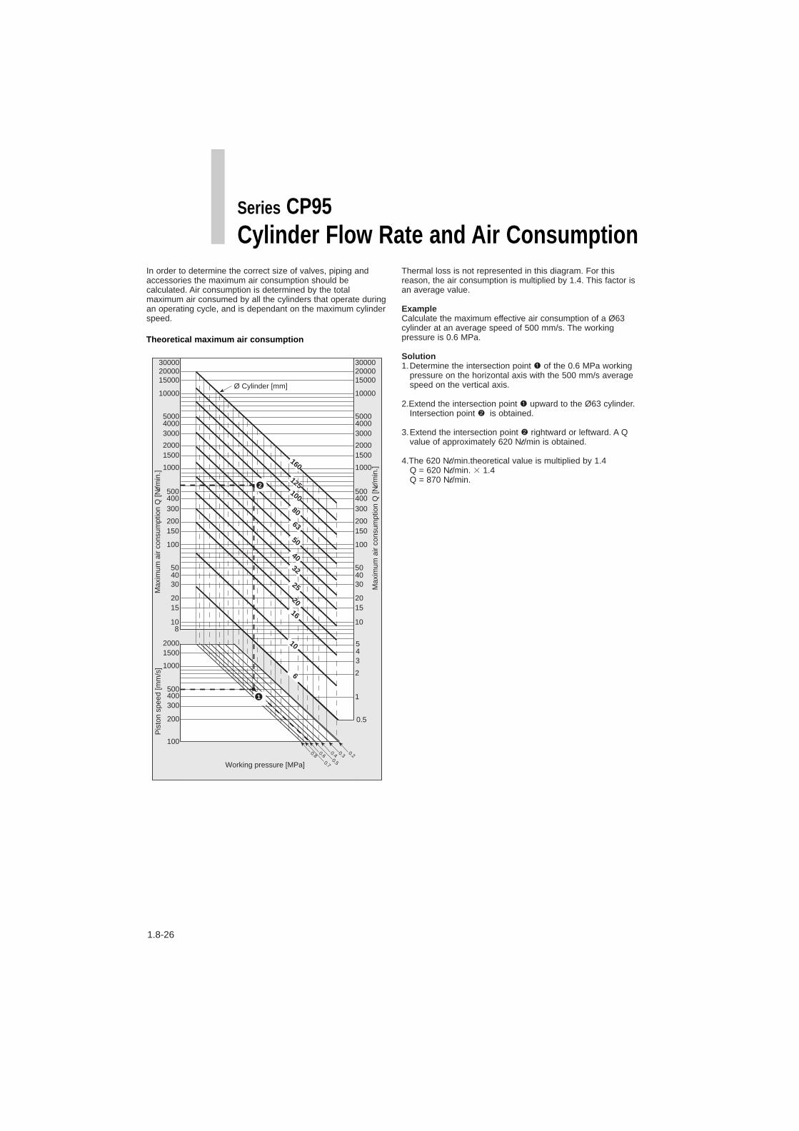
In order to determine the correct size of valves, piping andaccessories the maximum air consumption should becalculated. Air consumption is determined by the totalmaximum air consumed by all the cylinders that operate duringan operating cycle, and is dependant on the maximum cylinderspeed.
Thermal loss is not represented in this diagram. For thisreason, the air consumption is multiplied by 1.4. This factor isan average value.
ExampleCalculate the maximum effective air consumption of a Ø63cylinder at an average speed of 500 mm/s. The workingpressure is 0.6 MPa.
Solution1.Determine the intersection point 1 of the 0.6 MPa working
pressure on the horizontal axis with the 500 mm/s averagespeed on the vertical axis.
2.Extend the intersection point 1 upward to the Ø63 cylinder.Intersection point 2 is obtained.
3.Extend the intersection point 2 rightward or leftward. A Qvalue of approximately 620 Nl/min is obtained.
4.The 620 Nl/min.theoretical value is multiplied by 1.4Q = 620 Nl/min. 1.4Q = 870 Nl/min.
Working pressure [MPa]
Pis
ton
spee
d [m
m/s
]M
axim
um a
ir co
nsum
ptio
n Q
[Nl/m
in.]
0.20.30.40.5
0.60.7
0.8
Ø Cylinder [mm]
10
15
3
2
4
1
0.5
5
100
10000
1000
2000
8
Max
imum
air
cons
umpt
ion
Q [N
l/m
in.]
20
304050
150200
300400500
15002000
300040005000
150002000030000
10
15
100
10000
1000
20
304050
150200
300400500
15002000
300040005000
150002000030000
1500
1000
500400300
200
100
6
10
16
20
25
32
40
50
63
80
100
125
160
1
2
Theoretical maximum air consumption
Series CP95Cylinder Flow Rate and Air Consumption

1.8-27
In order to find the appropiate size of the compressor and thecompressed air supply. It is necessary to determine theaverage compressed air consumption.
Average theoretical air consumption of cylinders in acycle/m. (1 cycle = SWITCH ON/SWITCH OFF)
Example:Cylinder diameter: Ø50 mmStroke: 600 mmWorking pressure: 0.5 MPaCycles: 5 per minuteBore size: 6 mmPiping length (between the cylinder and the valve): 2 m
Cylinder air consumption1.Determine the intersection point 1 of a 0.5 MPa working
pressure with a stroke of 600 mm.2.Extend the intersection point 1 upward to the intersection
point 2 where a Ø50 mm is represented.3.Extend the intersection point 2 rightward or leftward. The Q
value of 13.5 Nl/min. is obtained. 4.The value of 13.5 Nl/min. is multiplied by 1.4 and by the
number of cycles.Q1 = 13.5 Nl/min. 1.4 5 cycles
= 94.5 Nl/min.
Thermal loss is not represented in this diagram. For thisreason, the air consumption is multiplied by 1.4. This factor isan average value.
Theoretical air consumption of compressed air piping
Air consumption of compressed air piping
5.Determine the intersection point 1 of a 0.5 MPa workingpressure with a piping length of 2m.
6.Extend the intersection point 1 upward to a Ø6 piping boresize. Intersection point 2 is obtained.
7.Extend the intersection point 2 rightward or leftward.Value: Q = 0.56 Nl/min.
8.The value of 0.56 Nl/min. is multiplied by 1.4 and by thenumber of cycles.Q2 = 0.56 Nl/min. 1.4 5 cycles
= 3.92 Nl/min.
Total air consumption of compressed air cylinderand piping:Q = Q1 + Q2 = 94.5 Nl/min. + 4 Nl/min.Q = 98.5 Nl/min.
Working pressure [MPa]
Str
oke
[mm
] A
ir co
nsum
ptio
n Q
[Nl/m
in.]
Air
cons
umpt
ion
Q [N
l/min
.]
50
100
150200300400500
1000
15002000
300040005000
0.6
1
1.52345
10
1520304050
100
150200300400500
1000
150020003000
1
1.52345
10
1520304050
100
150200300400500
1000
150020003000
0.50.40.30.20.150.1
0.050.040.03
0.020.0150.01
0.20.30.40.5
0.60.7
0.8
Ø cylinder [mm]
6
8063
50
32
252016
10
40
100
125
160
10
16
20
25
32
40
50
63
80
125
160
6
100
2
1
Working pressure [MPa]
Pip
ing
leng
th [m
] A
ir co
nsum
ptio
n Q
[Nl/m
in.]
0.20.30.40.5
0.60.7
0.8
Piping bore size[mm]
1
0.3
2
345
10 10
20
3
2
4
1
0.03
0.50.40.3
0.2
0.5
5
0.05
0.40.3
0.2
0.04
0.1
1
1.5
2
3
45
10
20
Air
cons
umpt
ion
Q [N
l/min
.]
0.40.5
0.02
0.01
0.005
2.5
4
5
6
7.5
8
12
9
2
1
Series CP95Average air consumption of compressed air cylinders and piping

1.8-28
Series CP95
The table below indicates the maximum stroke with differentmounting accessories. The values are for standard applicationswhen a cylinder drives a load (m) that corresponds to thecylinder theoretical output which results from a determinedworking pressure. If the rod diameter is not the appropiate onein relation to the pressure and the stroke, a longer strokecylinder should be selected or pressure should be reduced.
Mounting type Accessories Pressure Bore (mm)[MPa] 32 40 50 63 80 100b
L F (front) G (rear) 0.2 680 – – 980 1220 14100.3 540 – 1020 790 980 1140
L 0.4 460 700 880 680 840 980• 0.5 410 630 780 610 750 880F (front) 0.6 370 580 710 550 680 800
0.7 340 520 650 500 620 7300.8 310 480 600 460 580 6800.9 290 450 570 430 540 6301 270 420 530 400 510 5900.2 580 450 580 430 540 6300.3 450 350 460 340 420 5000.4 370 300 390 280 350 420
G (rear) 0.5 310 260 340 250 310 3700.6 270 230 300 220 270 3300.7 240 210 270 190 240 2900.8 210 190 250 170 220 2700.9 190 170 230 160 200 2401 170 160 210 140 190 220
C•D 0.2 – – 1200 920 1150 13300.3 – 760 960 730 910 1050
C 0.4 – 640 820 620 770 890• 0.5 – 570 720 540 680 780D 0.6 630 510 650 490 610 700
0.7 560 460 600 440 550 6400.8 510 430 550 400 510 5800.9 470 400 510 380 470 5501 430 370 480 350 440 510
Allowable theoretical strokes (mm)
Maximum stroke determination
G – Rear flangeF – Front flangeL – FootC – Male rear clevisD – Female rear clevis

1.8-29
Mounting type Accessories Pressure Bore (mm)[MPa] 32 40 50 63 80 100
L F (front) G (rear) L 0.2• 0.3F (front) 0.4
0.50.60.70.80.91 *) *) *) *) *) *)0.2 – – – – –
G (rear) 0.3 – – 1160 1360 –0.4 – – 940 1160 13500.5 – 1080 830 1020 11900.6 770 980 750 920 10800.7 700 900 680 850 9900.8 650 830 630 780 9100.9 610 790 590 740 8601 *) 580 740 560 690 810
L F (front) F (rear) L 0.2• 0.3F (front) 0 .4
0.50.60.70.80.91 *) *) *) *) *) *)
G (rear) 0.2 – – – –0.3 – – – –0.4 – – – –0.5 – – – –0.6 – 1010 1380 –0.7 – 1020 1270 14700.8 – 950 1180 13800.9 1160 890 1110 12901 *) *) 1090 840 1040 1220
Allowable theoretical strokes (mm)
Maximum stroke determination
*) The maximum standard stroke should be used depending on the cylinder diameter (Refer to page 11 below for standardstrokes).
G – Rear flangeF – Front flangeL – FootC – Male rear clevisD – Female rear clevis
ISO/VDMA Air Cylinders Series CP95
Safety Instructions
These safety instructions are intended to prevent a hazardous situation and/or equipment damage. These instructions indicate the level of potential hazard by a label of "Caution", "Warning" or "Danger". To ensure safety, be sure to observe ISO 4414 Note 1), JIS B 8370 Note 2) and other safety practices.
1 The compatibility of pneumatic equipment is the responsibility of the person who designs the pneumatic system or decides its specifications.Since the products specified here are used in various operating conditions, their compatibility for the specific pneumatic system must be based on specifications or after analysis and/or tests to meet your specific requirements.
2 Only trained personnel should operate pneumatically operated machinery and equipment.Compressed air can be dangerous if an operator is unfamiliar with it. Assembly, handling or repair of pneumatic systems should be performed by trained and experienced operators.
3 Do not service machinery/equipment or attempt to remove components until safety is confirmed.
1.Inspection and maintenance of machinery/equipment should only be performed after confirmation of safe locked-out control positions.
2.When equipment is to be removed, confirm the safety process as mentioned above. Cut the supply pressure for this equipment and exhaust all residual compressed air in the system.
3.Before machinery/equipment is re-started, take measures to prevent shooting-out of cylinder piston rod, etc. (Bleed air into the system gradually to create back-pressure.)
4 Contact SMC if the product is to be used in any of the following conditions:1.Conditions and environments beyond the given specifications, or if product is used outdoors.2.Installation on equipment in conjuction with atomic energy, railway, air navigation, vehicles, medical
equipment, food and beverages, recreation equipment, emergency stop circuits, press applications, or safety equipment.
3.An application which has the possibility of having negative effects on people, property, or animals, requiring special safety analysis.
Note 1) ISO 4414 : Pneumatic fluid power -- Recommendations for the application of equipment to transmission and control systems.
Note 2) JIS B 8370 : Pneumatic system axiom.
Warning
Caution : Operator error could result in injury or equipment damage.
Warning : Operator error could result in serious injury or loss of life.
Danger : In extreme conditions, there is a possible result of serious injury or loss of life.
Series CP95
1.8-30

1.8-31
Precautions on design Mounting
Selection
1.When mounting a cylinder in vertical position, the rod maycome out due to an abnormal pressure drop.
2.A protective cover is recommended to minimize the risk ofpersonal injury.
3.Securely tighten all stationary parts and connected parts sothat they will not become loose.
4.Consider a possible drop in operating pressure due to apower outage, etc.
5.Design the system circuitry in order to prevent suddenlurching of driven objects.
6.Consider emergency stops.7.Consider the action when operation is restarted after an
emergency stop or abnormal stop. Design the machinery sothat human injury or equipment damage will not occur uponrestart of operation.
Warning
Caution1.Check the catalogue specifications.2.Use a speed controller to adjust the cylinder drive speed,
gradually increasing from a low speed to the desired speedsetting.
Security precautions1.Strokes must not exceed the specified limits.2.Higher speed than specified may cause malfunction to the
end of stroke cushioning.3.When operating with long strokes, an intermediate band
should be used to stabilize the rod (danger of bending).
Piston maximum speed When an auto switch is placed at an intermediate position of the stroke and the piston speed is too high, the operating time will be shortened and the load may not operate properly.The maximum detectable piston speed is:
Example:The operating range of a D-A73L Reed switch mounted in aCP95 cylinder is 8 mm. The operating time required tooperate an electric valve is 30 ms = 0.003 s.
Warning1.Make sure that there are no variations in the alignment
between the rod centre and the load centre.2. If a guide is required, make sure transverse forces do not
occur.3.Avoid scratches on the rod. 4.Do not use until you verify that the equipment can operate
properly.5.The product should be mounted and operated after thoroughly
reading the manual and understanding its contents.6. Remove the packing of the air components, only at the
moment of its mounting.
Auto switch operating range [mm]Time load applied [s]
x100V=
8 mm0.0305 s
= 266 mm/sMaximum piston speed V =
Wiring
Caution1. Be sure that piping diameters are bigger than the connection
thread diameters.2. Before piping is connected, it should be thoroughly blown out
with air (flushing) or washed to remove dust or other debrisfrom inside the pipe.
3. Be certain that sealing material does not get inside the piping.4. When pipe tape is used, leave 1.5 to 2 thread ridges exposed
at the end of the pipe fitting.
Wrappingdirection
Pipe tapeExpose approx. 1.5 to 2 threads
Lubrication
Caution1. The cylinders have been lubricated for life at the factory and
can be used without any further lubrication.
Air supply
Warning1. Use clean air.2. Install air filters.3. Install a water separator after the cooler.4. Use the product within the specified range of fluid and
ambient temperature.
Series CP95Cylinder precautionsBe sure to read before handling.
(continued overleaf…)

1.8-32
Operating Environment
1.Do not operate in environments with corrosive gases, seawater, water or steam.
2. In locations where there is contact with spatter from water oroil, implement suitable protective measures.
3. If the cylinders are equipped with auto switches, do notoperate in locations where there are strong magnetic fields.
Warning
End of stroke cushioning
1.Set screw adjusting.The set screw has been already adjusted at the factory.Once it has been used, the set screw must be readjusted.Take into account the operating environment as well as theload size and weight. The effectivity of the end of strokecushioning is shortened by the clockwise screw turn. Theset screw should be secured by a locking washer.
2.Do not operate the cylinder when the set screw has beencompletely tightened.
Caution
Series CP95
Cylinder mounting
1.The maximum tightening torque must not exceed thespecified diameter limits, because it may reduce the non-rotating guide accuracy.
2.When mounting rod accessories, be sure that moment doesnot occur to the ball joint piston rod in the cylinderheadcover. Do not use an adjustable angle wrench on theoperating surface of the rod.
Warning
Cylinder precautions continued
1.8-33
Auto Switch Precautions
1.Confirm the specifications.2.When multiple auto switch cylinders are used in close
proximity, magnetic field interference may cause theswitches to malfunction. Maintain a minimum cylinderseparation of 40 mm.
3.Wiring should be kept as short as possible.4.Do not touch the piston rod when operating the cylinder.5.Avoid close contact with magnetic substances (something
attracted by a magnet), as the piston has a magnet ringwhich detects the magnetic force.
6.Lead wire colours of Reed and Solid state switches havebeen changed. These changes have been validated forproduction beginning September 1997.
Caution
Old New
Power supply(+) Red Brown
GND (–) Black Blue
Output White Black
Old New
Output (+) Red Brown
Output (–) Black Blue
2 wire
3 wire
Auto switch wiring1. Load must not exceed the specified current and voltage
limits.2.Be sure to connect the load before power is applied.3. Switches with indicator light have polarity. The brown lead
wire is (+), and the blue lead wire is (-). If connections arereversed, a switch will operate, however, the light emittingdiode will not light up.
4.When a switch with an indicator light operates under thespecified current, even though the switch operates normally,the indicator light may hardly light up or may not light up.
5. A voltage drop affects every auto switch when connected inseries because of internal resistance in the light emittingdiode.
6.When operating under a specified voltage, the internalvoltage drop in the indicator light may cause the loadmalfunction.
7. If the internal voltage drop causes a problem, select aswitch with no indicator light.
Auto Switch mounting1. Although Reed switches have a 30G impact resistance,
avoid bumps or excessive impacts.2.Do not use in an area where magnetic fields are generated
in order to avoid switches malfunction.3. Avoid repeatedly bending or stretching lead wires.4. Although switches satisfy the IEC standard IP67 structure
(JIS C 0920: anti-immersion structure), do not use switchesin applications where continually exposed to water, oil, coolant liquid, etc.
Wiring
1.Confirm proper insulation of wiring.2.Do not wire with high voltage lines.3.Avoid incorrect wiring.
Warning
Operating environment
1.Never use in an atmosphere of explosive gases.2.Do not use in an area where magnetic fields are generated.3.Do not use in an environment where the auto switch will be
continually exposed to water.4.Do not use in an environment with oil or chemicals.5.Consult SMC if switches are used where there are
temperature cycles other than normal temperature changes. 6.Do not use in locations where excessive impacts are
generated. If an impact of 30G or more is applied to aswitch, the signal may be interrupted for 1ms or less.Consult SMC the need of using a solid state switchdepending on the environment.
7.Avoid accumulation of iron powder or close contact withmagnetic substances.
Warning
Series CP95Auto Switch PrecautionsBe sure to read before handling.
(continued overleaf…)
1.8-34
Reed switch precautions
Noncontact switches are generally used in applicationswhere other switches which are operated mechanically donot provide an optimal functioning in adverse environmentalconditions, such as high frequency, dusty, dirty or very humidconditions.
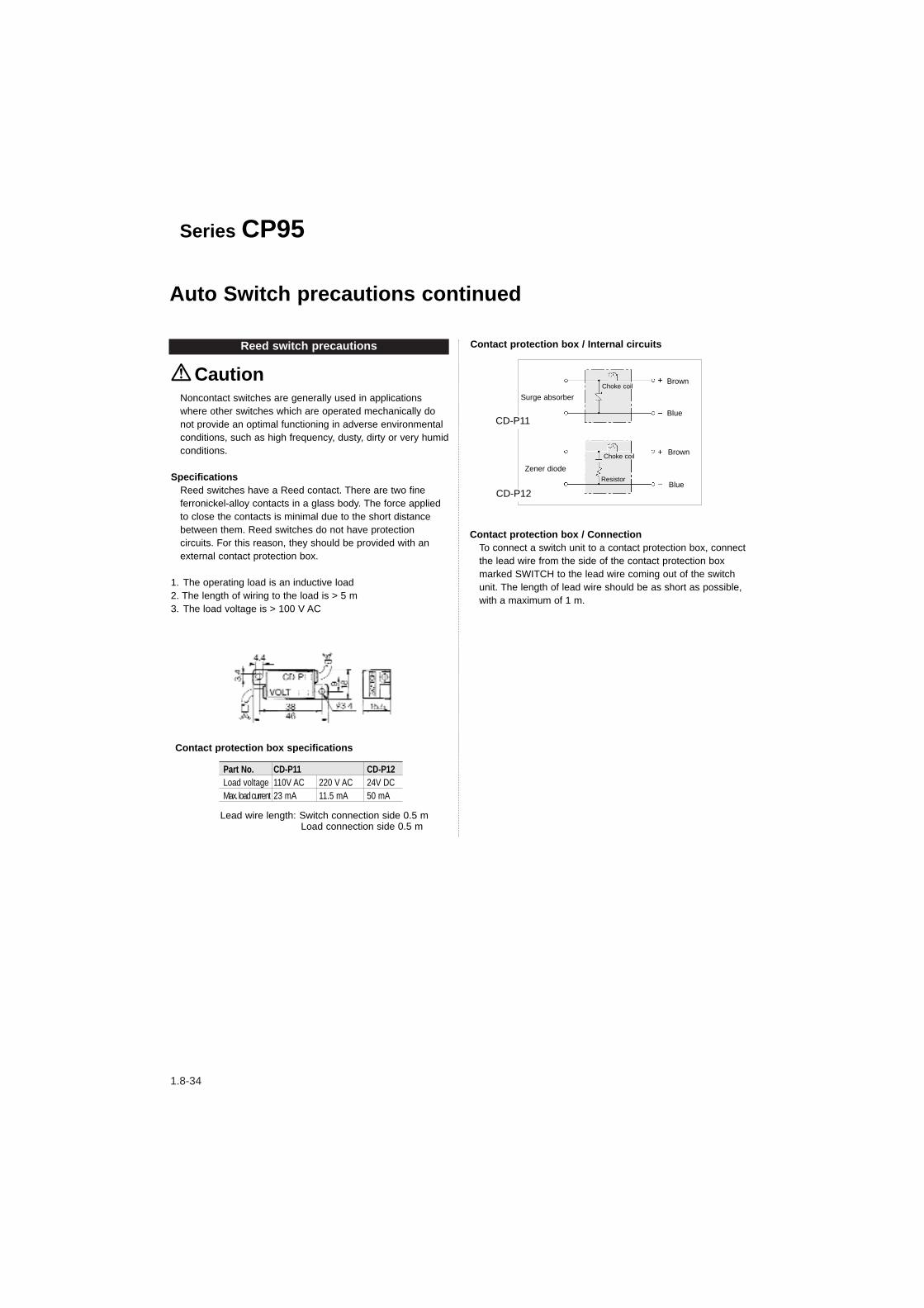
SpecificationsReed switches have a Reed contact. There are two fineferronickel-alloy contacts in a glass body. The force appliedto close the contacts is minimal due to the short distancebetween them. Reed switches do not have protectioncircuits. For this reason, they should be provided with anexternal contact protection box.
1. The operating load is an inductive load2. The length of wiring to the load is > 5 m3. The load voltage is > 100 V AC
Caution
Part No. CD-P11 CD-P12Load voltage 110V AC 220 V AC 24V DCMax. load current 23 mA 11.5 mA 50 mA
Contact protection box specifications
Lead wire length: Switch connection side 0.5 mLoad connection side 0.5 m
Contact protection box / Internal circuits
CD-P11
CD-P12
Contact protection box / ConnectionTo connect a switch unit to a contact protection box, connectthe lead wire from the side of the contact protection boxmarked SWITCH to the lead wire coming out of the switchunit. The length of lead wire should be as short as possible,with a maximum of 1 m.
Series CP95
Brown
Blue
Brown
Blue
Surge absorber
Zener diode
Choke coil
Choke coil
Resistor
Auto Switch precautions continued
1.8-35
Main Index Series CP95
Page No.
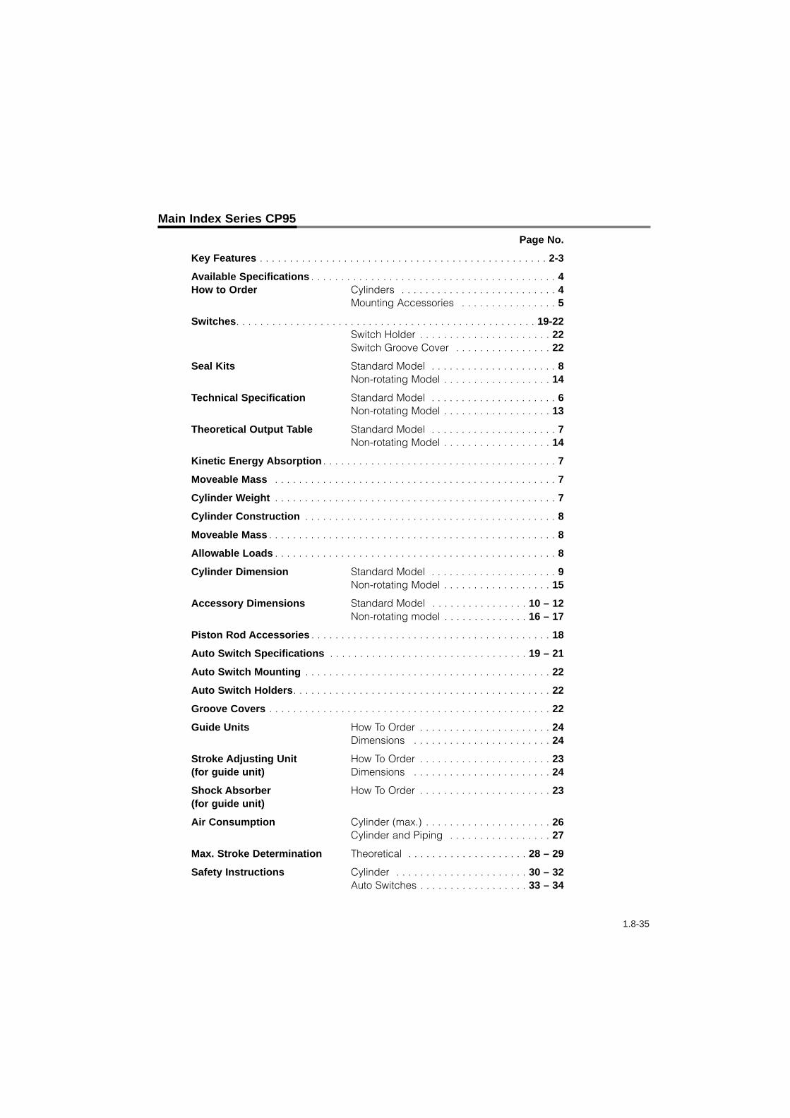
Key Features . . . . . . . . . . . . . . . . . . . . . . . . . . . . . . . . . . . . . . . . . . . . . . . . 2-3
Available Specifications . . . . . . . . . . . . . . . . . . . . . . . . . . . . . . . . . . . . . . . . . 4How to Order Cylinders . . . . . . . . . . . . . . . . . . . . . . . . . . 4
Mounting Accessories . . . . . . . . . . . . . . . . 5
Switches. . . . . . . . . . . . . . . . . . . . . . . . . . . . . . . . . . . . . . . . . . . . . . . . . . 19-22Switch Holder . . . . . . . . . . . . . . . . . . . . . . 22Switch Groove Cover . . . . . . . . . . . . . . . . 22
Seal Kits Standard Model . . . . . . . . . . . . . . . . . . . . . 8Non-rotating Model . . . . . . . . . . . . . . . . . . 14
Technical Specification Standard Model . . . . . . . . . . . . . . . . . . . . . 6Non-rotating Model . . . . . . . . . . . . . . . . . . 13
Theoretical Output Table Standard Model . . . . . . . . . . . . . . . . . . . . . 7Non-rotating Model . . . . . . . . . . . . . . . . . . 14
Kinetic Energy Absorption . . . . . . . . . . . . . . . . . . . . . . . . . . . . . . . . . . . . . . . 7
Moveable Mass . . . . . . . . . . . . . . . . . . . . . . . . . . . . . . . . . . . . . . . . . . . . . . . 7
Cylinder Weight . . . . . . . . . . . . . . . . . . . . . . . . . . . . . . . . . . . . . . . . . . . . . . . 7
Cylinder Construction . . . . . . . . . . . . . . . . . . . . . . . . . . . . . . . . . . . . . . . . . . 8
Moveable Mass . . . . . . . . . . . . . . . . . . . . . . . . . . . . . . . . . . . . . . . . . . . . . . . . 8
Allowable Loads . . . . . . . . . . . . . . . . . . . . . . . . . . . . . . . . . . . . . . . . . . . . . . . 8
Cylinder Dimension Standard Model . . . . . . . . . . . . . . . . . . . . . 9Non-rotating Model . . . . . . . . . . . . . . . . . . 15
Accessory Dimensions Standard Model . . . . . . . . . . . . . . . . 10 – 12Non-rotating model . . . . . . . . . . . . . . 16 – 17
Piston Rod Accessories . . . . . . . . . . . . . . . . . . . . . . . . . . . . . . . . . . . . . . . . 18
Auto Switch Specifications . . . . . . . . . . . . . . . . . . . . . . . . . . . . . . . . . 19 – 21
Auto Switch Mounting . . . . . . . . . . . . . . . . . . . . . . . . . . . . . . . . . . . . . . . . . 22
Auto Switch Holders. . . . . . . . . . . . . . . . . . . . . . . . . . . . . . . . . . . . . . . . . . . 22
Groove Covers . . . . . . . . . . . . . . . . . . . . . . . . . . . . . . . . . . . . . . . . . . . . . . . 22
Guide Units How To Order . . . . . . . . . . . . . . . . . . . . . . 24Dimensions . . . . . . . . . . . . . . . . . . . . . . . 24
Stroke Adjusting Unit How To Order . . . . . . . . . . . . . . . . . . . . . . 23(for guide unit) Dimensions . . . . . . . . . . . . . . . . . . . . . . . 24
Shock Absorber How To Order . . . . . . . . . . . . . . . . . . . . . . 23(for guide unit)
Air Consumption Cylinder (max.) . . . . . . . . . . . . . . . . . . . . . 26Cylinder and Piping . . . . . . . . . . . . . . . . . 27
Max. Stroke Determination Theoretical . . . . . . . . . . . . . . . . . . . . 28 – 29
Safety Instructions Cylinder . . . . . . . . . . . . . . . . . . . . . . 30 – 32Auto Switches . . . . . . . . . . . . . . . . . . 33 – 34

1.8-36