Embed Size (px)
Citation preview

HMS-1650 Programmer’s Guide
Version: 03.09.17
Triatek HMS-1650Fume Hood Controller

Triatek reserves the right to change product specifications without notice.
PROGRAMMER’S GUIDE
Notes
HMS-1650
Triatek reserves the right to change product specifications without notice.
- i -
Triatek reserves the right to change product specifications without notice. Triatek reserves the right to change product specifications without notice.
Read This First
The HMS-1650 Programmers Guide provides complete details for configuring Triatek’s HMS-1650 series of laboratory fume hood controllers.
For more details and complete specifications, please refer to the HMS-1650 Installation Guide. This document provides reference information for the HMS-1650 user menus and is organized as follows:
• Overview• Main Setup Menu• Unit Setup• System Setup• Display Setup• Screen Configuration• Diagnostics• Typical Application for the HMS-1650• Appendix A: PID Tutorial• Appendix B: Module Settings
PROGRAMMER’S GUIDE
HMS-1650
Triatek reserves the right to change product specifications without notice.
- ii -
Due to continuous improvement, TRIATEK reserves the right to change product specifications without notice.
HMS-1650
Due to continuous improvement, Triatek reserves the right to change product specifications without notice. Due to continuous improvement, Triatek reserves the right to change product specifications without notice.
Read This First …………………………………………………………………………………………………………………………………… iiSpecifications ………………………………………………………………………………………………………………………………… 1 - 2 Overview ………………………………………………………………………………………………………………………………………… 4Main Setup Menu ………………………………………………………………………………………………………………………………… 5Unit Setup …………………………………………………………………………………………………………………………………… 6 - 19
Introduction ………………………………………………………………………………………………………………………………… 6Configuring Controller Setting …………………………………………………………………………………………………………… 7Setting up the Main Sensor Input …………………………………………………………………………………………………… 7 - 8Setting up the Exhaust Damper Control Output …………………………………………………………………………………… 8 - 9Setting up the Sash Switch ………………………………………………………………………………………………………… 9 - 10Setting up the Alarm Relay ……………………………………………………………………………………………………………… 10Adjusting the PID Loop Settings …………………………………………………………………………………………………… 10 - 11Configuring the Alarm Parameters ……………………………………………………………………………………………………… 11Setting up the Alarm Buzzer ……………………………………………………………………………………………………… 11 - 12Selecting Engineering Units …………………………………………………………………………………………………………… 12Configuring Hood Settings ……………………………………………………………………………………………………………… 13Field Calibrating the Sidewall Sensor …………………………………………………………………………………………… 13 - 14Setting the Fume Hood Operating Mode ………………………………………………………………………………………… 14 - 15Configuring Target Setpoints …………………………………………………………………………………………………………… 15Configuring ExAccel Settings …………………………………………………………………………………………………………… 15Configuring Sash Settings ………………………………………………………………………………………………………… 15 - 16Field Calibrating the Sash Position Sensor …………………………………………………………………………………………… 16Calibrating the Sash Control Feature ……………………………………………………………………………………………… 16 - 17Configuring Network Settings …………………………………………………………………………………………………………… 17Setting up BACnet® Parameters …………………………………………………………………………………………………… 17 - 19Choosing the Baud Rate ………………………………………………………………………………………………………………… 19Setting the Network or MAC Address ………………………………………………………………………………………………… 19
System Setup …………………………………………………………………………………………………………………………… 20 - 34Configuring Secondary Analog Inputs …………………………………………………………………………………………… 20 - 21Configuring Secondary Analog Outputs ………………………………………………………………………………………………… 21Setting Up Analog Inputs For Pressure ………………………………………………………………………………………………… 21Setting Up Analog Inputs For Flow ……………………………………………………………………………………………… 21 - 24Setting Up Analog Inputs For Humidity ………………………………………………………………………………………………… 24Setting Up Analog Inputs For Monitoring Sash Position ……………………………………………………………………………… 25Setting Up Thermistor Inputs ……………………………………………………………………………………………………… 25 - 26Configuring Secondary Analog Outputs ………………………………………………………………………………………… 26 - 27Remapping the Secondary Analog Inputs …………………………………………………………………………………………… 27Configuring Secondary Digital Inputs …………………………………………………………………………………………… 27 - 28Configuring Secondary Relay Outputs …………………………………………………………………………………………… 28 - 29Configuring Secondary PID Loops …………………………………………………………………………………………………… 29Configuring Universal Alarm Settings …………………………………………………………………………………………… 29 - 30Enabling Individual Visual Alarms ………………………………………………………………………………………………… 30 - 32Enabling Individual Audible Alarms ……………………………………………………………………………………………… 32 - 33Configuring Engineering Units For Secondary Inputs ……………………………………………………………………………… 33Managing System Passwords ………………………………………………………………………………………………………… 33Adding a New Password ………………………………………………………………………………………………………… 33 - 34Editing an Existing Password ………………………………………………………………………………………………………… 34Deleting an Existing Password ………………………………………………………………………………………………………… 34Purging All Passwords …………………………………………………………………………………………………………………… 35
PROGRAMMER’S GUIDE
Table of Contents
Triatek reserves the right to change product specifications without notice. Triatek reserves the right to change product specifications without notice.
Due to continuous improvement, TRIATEK reserves the right to change product specifications without notice.Due to continuous improvement, Triatek reserves the right to change product specifications without notice.
HMS-1650
Due to continuous improvement, Triatek reserves the right to change product specifications without notice.
PROGRAMMER’S GUIDE
Table of Contents
Display Setup ……………………………………………………………………………………………………………………………… 36 - 38Introduction ……………………………………………………………………………………………………………………………… 36Modifying Input Names ………………………………………………………………………………………………………………… 36Selecting the Display Options ……………………………………………………………………………………………………… 36 - 37Setting System Time & Date ……………………………………………………………………………………………………… 37 - 38Selecting the Backlighting Intensity …………………………………………………………………………………………………… 38Selecting an Alternate Language ……………………………………………………………………………………………………… 38
Diagnostics ……………………………………………………………………………………………………………………………… 39 - 42Introduction ………………………………………………………………………………………………………………………………… 39Getting System Information …………………………………………………………………………………………………………… 39Using Override Capabilities …………………………………………………………………………………………………………… 40Using the Real-Time View Option ………………………………………………………………………………………………… 40 - 41Using the Self-Test ……………………………………………………………………………………………………………………… 41Resetting the HMS-1650 ………………………………………………………………………………………………………………… 42
Typical Application for the HMS-1650 ……………………………………………………………………………………………… 43 - 49Introductions ……………………………………………………………………………………………………………………………… 43Wiring Details …………………………………………………………………………………………………………………………… 43Configuring Hardware Resources …………………………………………………………………………………………………… 43Confirm Sidewall Velocity Sensor Setting …………………………………………………………………………………………… 43Configure Sash Position Sensor ……………………………………………………………………………………………………… 43Configure Humidity Sensor …………………………………………………………………………………………………………… 44Configure Flow Sensor ………………………………………………………………………………………………………………… 44Configure Temperature Sensor ………………………………………………………………………………………………………… 44Configuring Analog Outputs …………………………………………………………………………………………………………… 44Configure Exhaust Damper Control …………………………………………………………………………………………………… 44Configuring Display Settings …………………………………………………………………………………………………………… 45Wiring Diagram …………………………………………………………………………………………………………………………… 46
PID Tutorial …………………………………………………………………………………………………………………………… A-1 – A-4Introduction ……………………………………………………………………………………………………………………………… A-2Control Loop Basics …………………………………………………………………………………………………………………… A-2PID Controller Theory …………………………………………………………………………………………………………… A-3 – A-3Proportional Term ……………………………………………………………………………………………………………………… A-3Integral Term …………………………………………………………………………………………………………………………… A-3Derivative Term ………………………………………………………………………………………………………………………… A-3
Summary ……………………………………………………………………………………………………………………………………… A-4Module Settings ……………………………………………………………………………………………………………………… B-1 – B-8
Configuring Display Module Settings (LON) ..……………………………………………………………………………………….. B-2Configuring Display Module Settings (BACnet) .……………………………………………………………………………………... B-3Configuring Main Controller Module Settings (BACnet) .…………………………………………………………………………….. B-4Configurations & Settings (BACnet) …………………………………………………………………………………………………… B-5BACnet Objects ...………………………………………………………………………………………………………………. B-6 – B-7Metasys N2 Objects ……………………………………………………………………………………………………………………… B-8
Flow Diagrams ……………………………………………………………………………………………………………………… B-10 – B-13 Unit Setup Tree ………………………………………………………………………………………………………………………… B-10 System Setup Tree …………………………………………………………………………………………………………………… B-11 Display Setup Tree …………………………………………………………………………………………………………………… B-12 Diagnostics Menu Tree ……………………………………………………………………………………………………………… B-13
Triatek reserves the right to change product specifications without notice.
Due to continuous improvement, TRIATEK reserves the right to change product specifications without notice.
- 1 -
HMS-1650
Due to continuous improvement, Triatek reserves the right to change product specifications without notice.
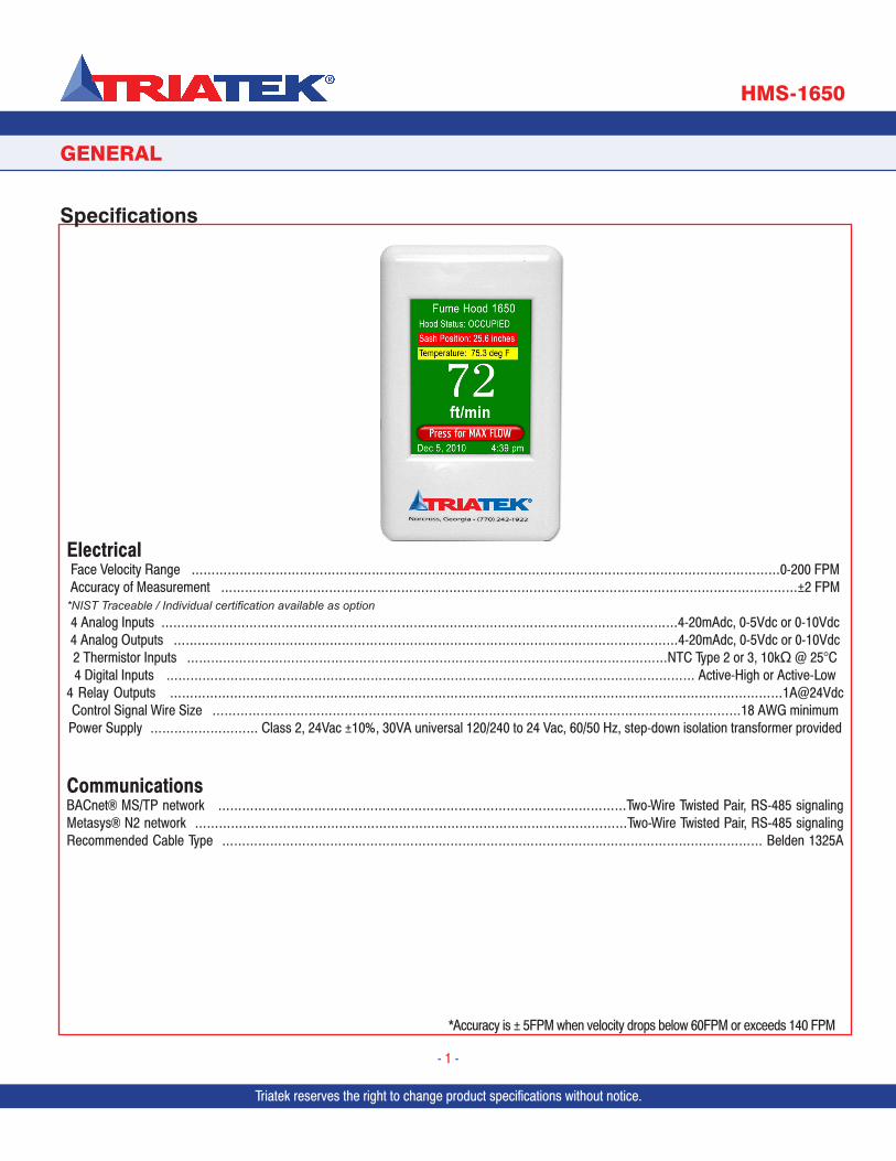
ElectricalFace Velocity Range …………………………………………………………………………………………………………………………………0-200 FPMAccuracy of Measurement ………………………………………………………………………………………………………………………………±2 FPM
*NIST Traceable / Individual certification available as option4 Analog Inputs …………………………………………………………………………………………………………………4-20mAdc, 0-5Vdc or 0-10Vdc4 Analog Outputs ………………………………………………………………………………………………………………4-20mAdc, 0-5Vdc or 0-10Vdc2 Thermistor Inputs …………………………………………………………………………………………………………NTC Type 2 or 3, 10kΩ @ 25°C4 Digital Inputs …………………………………………………………………………………………………………………… Active-High or Active-Low
4 Relay Outputs ………………………………………………………………………………………………………………………………………1A@24Vdc Control Signal Wire Size ……………………………………………………………………………………………………………………18 AWG minimumPower Supply ……………………… Class 2, 24Vac ±10%, 30VA universal 120/240 to 24 Vac, 60/50 Hz, step-down isolation transformer provided
CommunicationsBACnet® MS/TP network …………………………………………………………………………………………Two-Wire Twisted Pair, RS-485 signalingMetasys® N2 network ………………………………………………………………………………………………Two-Wire Twisted Pair, RS-485 signalingRecommended Cable Type ……………………………………………………………………………………………………………………… Belden 1325A
GENERAL
Specifications
Triatek reserves the right to change product specifications without notice. Triatek reserves the right to change product specifications without notice.
*Accuracy is ± 5FPM when velocity drops below 60FPM or exceeds 140 FPM
Due to continuous improvement, TRIATEK reserves the right to change product specifications without notice.Due to continuous improvement, Triatek reserves the right to change product specifications without notice.Triatek reserves the right to change product specifications without notice.
- 2 -
HMS-1650
GENERAL
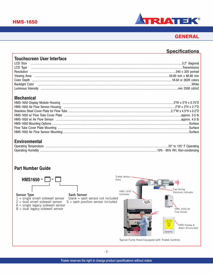
SpecificationsTouchscreen User InterfaceLCD Size ……………………………………………………………………………………………………………………………………………3.2” diagonalLCD Type ……………………………………………………………………………………………………………………………………………TransmissiveResolution ………………………………………………………………………………………………………………………………………240 x 320 portraitViewing Area ……………………………………………………………………………………………………………………………50.60 mm x 66.80 mmColor Depth …………………………………………………………………………………………………………………………………18-bit or 262K colorsBacklight Color ………………………………………………………………………………………………………………………………………………WhiteLuminous Intensity ………………………………………………………………………………………………………………………………min 2500 cd/m2
MechanicalHMS-1650 Display Module Housing ………………………………………………………………………………………………………3”W x 5”H x 0.75”DHMS-1650 Air Flow Sensor Housing ………………………………………………………………………………………………………2”W x 3”H x 2.7”DStainless Steel Cover Plate for Flow Tube ………………………………………………………………………………………………2.7”W x 4.5”H x 0.2”DHMS-1650 w/ Flow Tube Cover Plate ……………………………………………………………………………………………………………approx. 3.5 lbHMS-1650 w/ Air Flow Sensor ……………………………………………………………………………………………………………………approx. 4.0 lbHMS-1650 Mounting Options ………………………………………………………………………………………………………………………………SurfaceFlow Tube Cover Plate Mounting …………………………………………………………………………………………………………………………SurfaceHMS-1650 Air Flow Sensor Mounting ……………………………………………………………………………………………………………………Surface
EnvironmentalOperating Temperature …………………………………………………………………………………………………………………32° to 125° F OperatingOperating Humidity ……………………………………………………………………………………………………………10% - 95% RH, Non-condensing
Part Number Guide
Triatek reserves the right to change product specifications without notice.
HMS 1650 AirFlow Sensor
HMS 1650Controller
HMS Display & Alarm Annunciator
Triatek Venturi Valve
Typical Fume Hood Equipped with Triatek Controls
Fast ActingElectronic Actuator
HMS1650 - 1- 1
Sensor Type Sash Sensor1 = single smart sidewall sensor blank = sash sensor not included2 = dual smart sidewall sensor S = sash position sensor included A = single legacy sidewall sensorB = dual legacy sidewall sensor
Triatek reserves the right to change product specifications without notice.
PROGRAMMER’S GUIDE
HMS-1650
Triatek reserves the right to change product specifications without notice.
- 3 -
FAST ACTINGELECTRONIC ACTUATOR
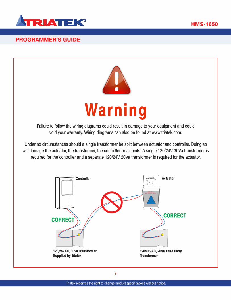
Controller Actuator
120/24VAC, 30Va TransformerSupplied by Triatek
120/24VAC, 20Va Third Party Transformer
CORRECTCORRECT
Warning
Failure to follow the wiring diagrams could result in damage to your equipment and could void your warranty. Wiring diagrams can also be found at www.triatek.com.
Under no circumstances should a single transformer be split between actuator and controller. Doing so will damage the actuator, the transformer, the controller or all units. A single 120/24V 30Va transformer is
required for the controller and a separate 120/24V 20Va transformer is required for the actuator.
Triatek reserves the right to change product specifications without notice. Triatek reserves the right to change product specifications without notice.
OVERVIEW
HMS-1650
Triatek reserves the right to change product specifications without notice.
- 4 -
HMS-1650 Overview
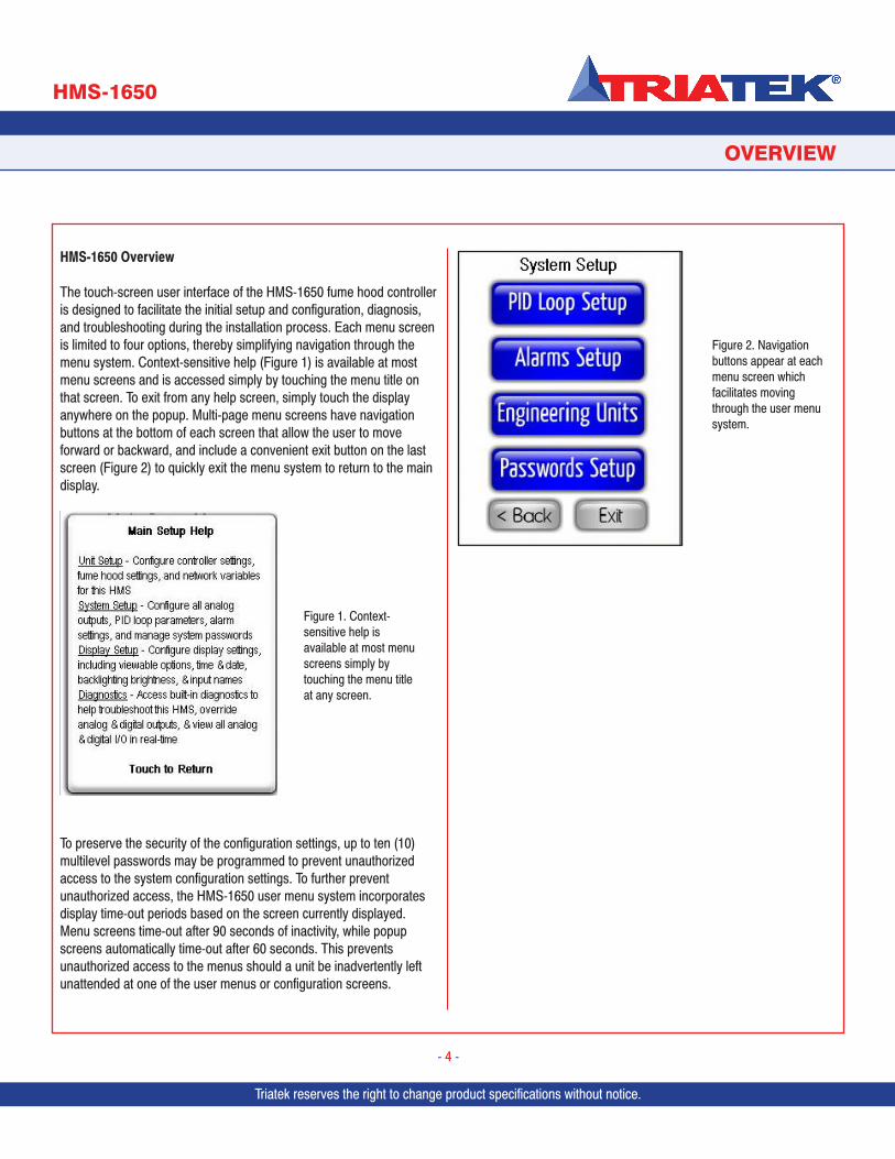
The touch-screen user interface of the HMS-1650 fume hood controller is designed to facilitate the initial setup and configuration, diagnosis, and troubleshooting during the installation process. Each menu screen is limited to four options, thereby simplifying navigation through the menu system. Context-sensitive help (Figure 1) is available at most menu screens and is accessed simply by touching the menu title on that screen. To exit from any help screen, simply touch the display anywhere on the popup. Multi-page menu screens have navigation buttons at the bottom of each screen that allow the user to move forward or backward, and include a convenient exit button on the last screen (Figure 2) to quickly exit the menu system to return to the main display.
To preserve the security of the configuration settings, up to ten (10) multilevel passwords may be programmed to prevent unauthorized access to the system configuration settings. To further prevent unauthorized access, the HMS-1650 user menu system incorporates display time-out periods based on the screen currently displayed. Menu screens time-out after 90 seconds of inactivity, while popup screens automatically time-out after 60 seconds. This prevents unauthorized access to the menus should a unit be inadvertently left unattended at one of the user menus or configuration screens.
Figure 2. Navigation buttons appear at each menu screen which facilitates moving through the user menu system.
Figure 1. Context-sensitive help is available at most menu screens simply by touching the menu title at any screen.
Triatek reserves the right to change product specifications without notice.
MAIN SETUP MENU
HMS-1650
Triatek reserves the right to change product specifications without notice.
- 5 -
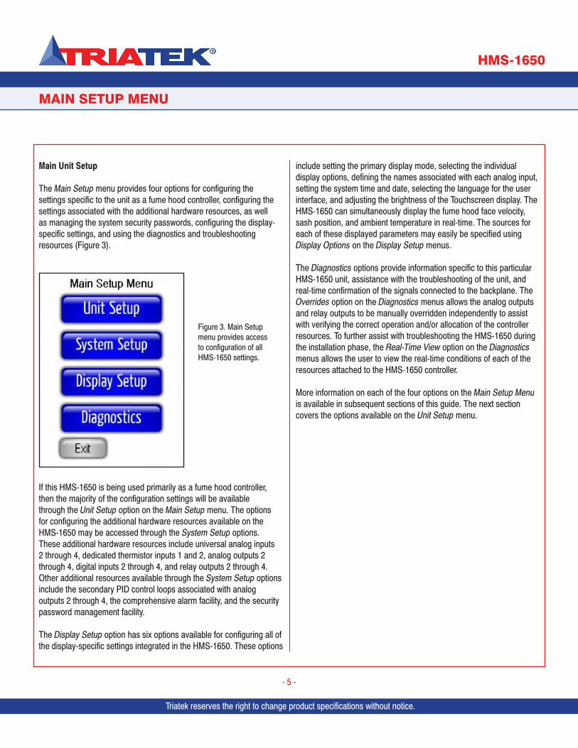
Main Unit Setup
The Main Setup menu provides four options for configuring the settings specific to the unit as a fume hood controller, configuring the settings associated with the additional hardware resources, as well as managing the system security passwords, configuring the display-specific settings, and using the diagnostics and troubleshooting resources (Figure 3).
If this HMS-1650 is being used primarily as a fume hood controller, then the majority of the configuration settings will be available through the Unit Setup option on the Main Setup menu. The options for configuring the additional hardware resources available on the HMS-1650 may be accessed through the System Setup options. These additional hardware resources include universal analog inputs 2 through 4, dedicated thermistor inputs 1 and 2, analog outputs 2 through 4, digital inputs 2 through 4, and relay outputs 2 through 4. Other additional resources available through the System Setup options include the secondary PID control loops associated with analog outputs 2 through 4, the comprehensive alarm facility, and the security password management facility.
The Display Setup option has six options available for configuring all of the display-specific settings integrated in the HMS-1650. These options
include setting the primary display mode, selecting the individual display options, defining the names associated with each analog input, setting the system time and date, selecting the language for the user interface, and adjusting the brightness of the Touchscreen display. The HMS-1650 can simultaneously display the fume hood face velocity, sash position, and ambient temperature in real-time. The sources for each of these displayed parameters may easily be specified using Display Options on the Display Setup menus.
The Diagnostics options provide information specific to this particular HMS-1650 unit, assistance with the troubleshooting of the unit, and real-time confirmation of the signals connected to the backplane. The Overrides option on the Diagnostics menus allows the analog outputs and relay outputs to be manually overridden independently to assist with verifying the correct operation and/or allocation of the controller resources. To further assist with troubleshooting the HMS-1650 during the installation phase, the Real-Time View option on the Diagnostics menus allows the user to view the real-time conditions of each of the resources attached to the HMS-1650 controller.
More information on each of the four options on the Main Setup Menu is available in subsequent sections of this guide. The next section covers the options available on the Unit Setup menu.
Figure 3. Main Setup menu provides access to configuration of all HMS-1650 settings.
Triatek reserves the right to change product specifications without notice. Triatek reserves the right to change product specifications without notice.
UNIT SETUP
HMS-1650
Triatek reserves the right to change product specifications without notice.
- 6 -
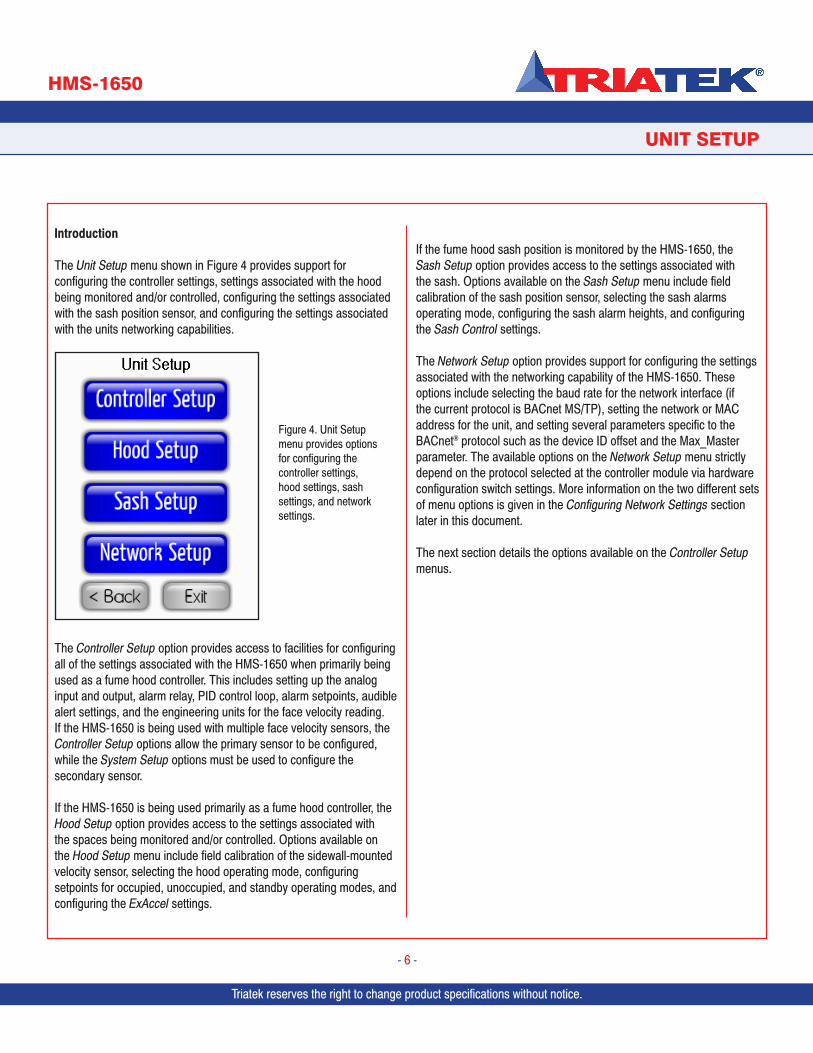
Introduction
The Unit Setup menu shown in Figure 4 provides support for configuring the controller settings, settings associated with the hood being monitored and/or controlled, configuring the settings associated with the sash position sensor, and configuring the settings associated with the units networking capabilities.
The Controller Setup option provides access to facilities for configuring all of the settings associated with the HMS-1650 when primarily being used as a fume hood controller. This includes setting up the analog input and output, alarm relay, PID control loop, alarm setpoints, audible alert settings, and the engineering units for the face velocity reading. If the HMS-1650 is being used with multiple face velocity sensors, the Controller Setup options allow the primary sensor to be configured, while the System Setup options must be used to configure the secondary sensor.
If the HMS-1650 is being used primarily as a fume hood controller, the Hood Setup option provides access to the settings associated with the spaces being monitored and/or controlled. Options available on the Hood Setup menu include field calibration of the sidewall-mounted velocity sensor, selecting the hood operating mode, configuring setpoints for occupied, unoccupied, and standby operating modes, and configuring the ExAccel settings.
If the fume hood sash position is monitored by the HMS-1650, the Sash Setup option provides access to the settings associated with the sash. Options available on the Sash Setup menu include field calibration of the sash position sensor, selecting the sash alarms operating mode, configuring the sash alarm heights, and configuring the Sash Control settings.
The Network Setup option provides support for configuring the settings associated with the networking capability of the HMS-1650. These options include selecting the baud rate for the network interface (if the current protocol is BACnet MS/TP), setting the network or MAC address for the unit, and setting several parameters specific to the BACnet® protocol such as the device ID offset and the Max_Master parameter. The available options on the Network Setup menu strictly depend on the protocol selected at the controller module via hardware configuration switch settings. More information on the two different sets of menu options is given in the Configuring Network Settings section later in this document.
The next section details the options available on the Controller Setup menus.
Figure 4. Unit Setup menu provides options for configuring the controller settings, hood settings, sash settings, and network settings.
Triatek reserves the right to change product specifications without notice.
UNIT SETUP
HMS-1650
Triatek reserves the right to change product specifications without notice.
- 7 -
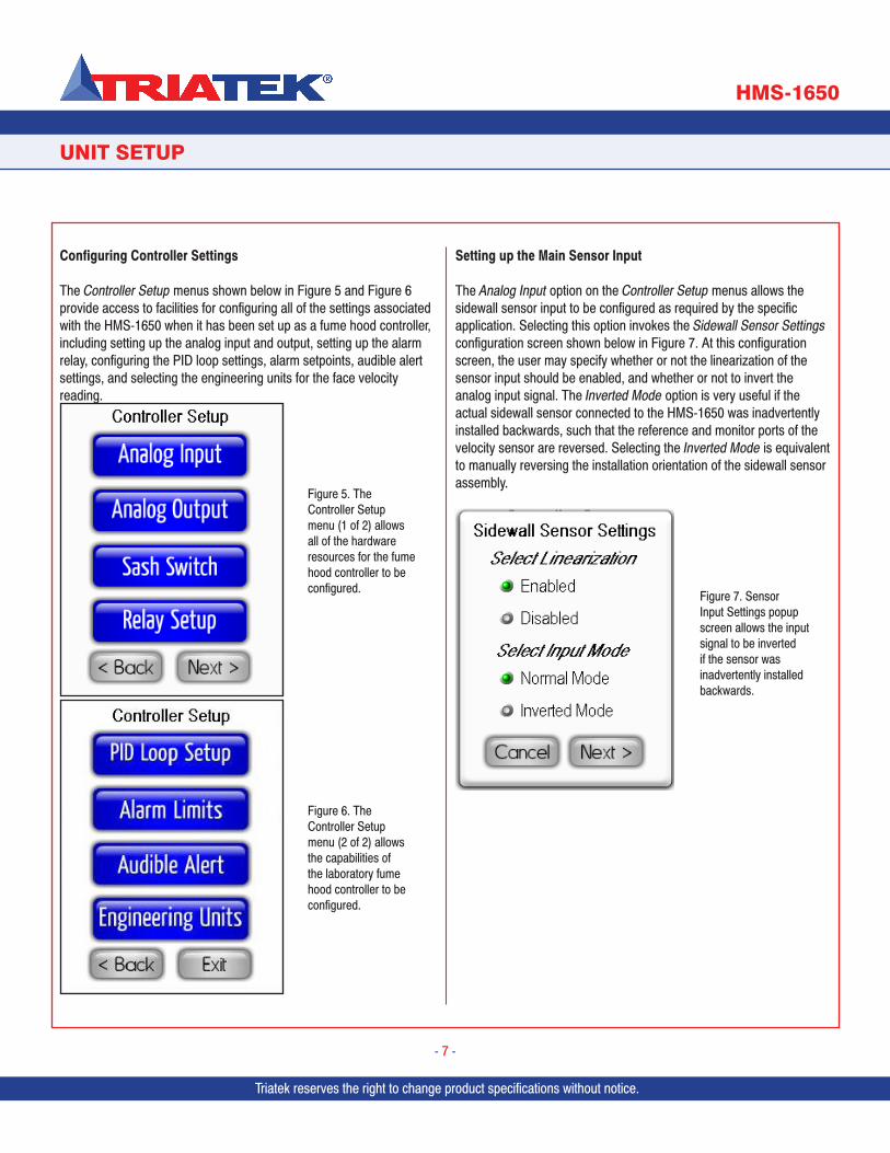
Configuring Controller Settings
The Controller Setup menus shown below in Figure 5 and Figure 6 provide access to facilities for configuring all of the settings associated with the HMS-1650 when it has been set up as a fume hood controller, including setting up the analog input and output, setting up the alarm relay, configuring the PID loop settings, alarm setpoints, audible alert settings, and selecting the engineering units for the face velocity reading.
Setting up the Main Sensor Input
The Analog Input option on the Controller Setup menus allows the sidewall sensor input to be configured as required by the specific application. Selecting this option invokes the Sidewall Sensor Settings configuration screen shown below in Figure 7. At this configuration screen, the user may specify whether or not the linearization of the sensor input should be enabled, and whether or not to invert the analog input signal. The Inverted Mode option is very useful if the actual sidewall sensor connected to the HMS-1650 was inadvertently installed backwards, such that the reference and monitor ports of the velocity sensor are reversed. Selecting the Inverted Mode is equivalent to manually reversing the installation orientation of the sidewall sensor assembly.
Figure 7. Sensor Input Settings popup screen allows the input signal to be inverted if the sensor was inadvertently installed backwards.
Figure 6. The Controller Setup menu (2 of 2) allows the capabilities of the laboratory fume hood controller to be configured.
Figure 5. The Controller Setup menu (1 of 2) allows all of the hardware resources for the fume hood controller to be configured.
Triatek reserves the right to change product specifications without notice. Triatek reserves the right to change product specifications without notice.
UNIT SETUP
HMS-1650
Triatek reserves the right to change product specifications without notice.
- 8 -
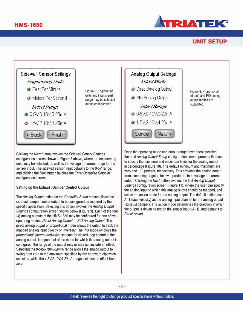
Clicking the Next button invokes the Sidewall Sensor Settings configuration screen shown in Figure 8 above, where the engineering units may be selected, as well as the voltage or current range for the sensor input. The sidewall sensor input defaults to the 0-5V range, and clicking the Next button invokes the Enter Occupied Setpoint configuration screen.
Setting up the Exhaust Damper Control Output
The Analog Output option on the Controller Setup menus allows the exhaust damper control output to be configured as required by the specific application. Selecting this option invokes the Analog Output Settings configuration screen shown below (Figure 9). Each of the four (4) analog outputs of the HMS-1650 may be configured for one of two operating modes: Direct Analog Output or PID Analog Output. The direct analog output or proportional mode allows the output to track the mapped analog input directly or inversely. The PID mode employs the proportional-integral-derivative scheme for closed-loop control of the analog output. Independent of the mode for which the analog output is configured, the range of the output may or may not include an offset. Selecting the 0-5V,0-10V,0-20mA range allows the analog output to swing from zero to the maximum specified by the hardware dipswitch selection, while the 1-5V,2-10V,4-20mA range includes an offset from zero.
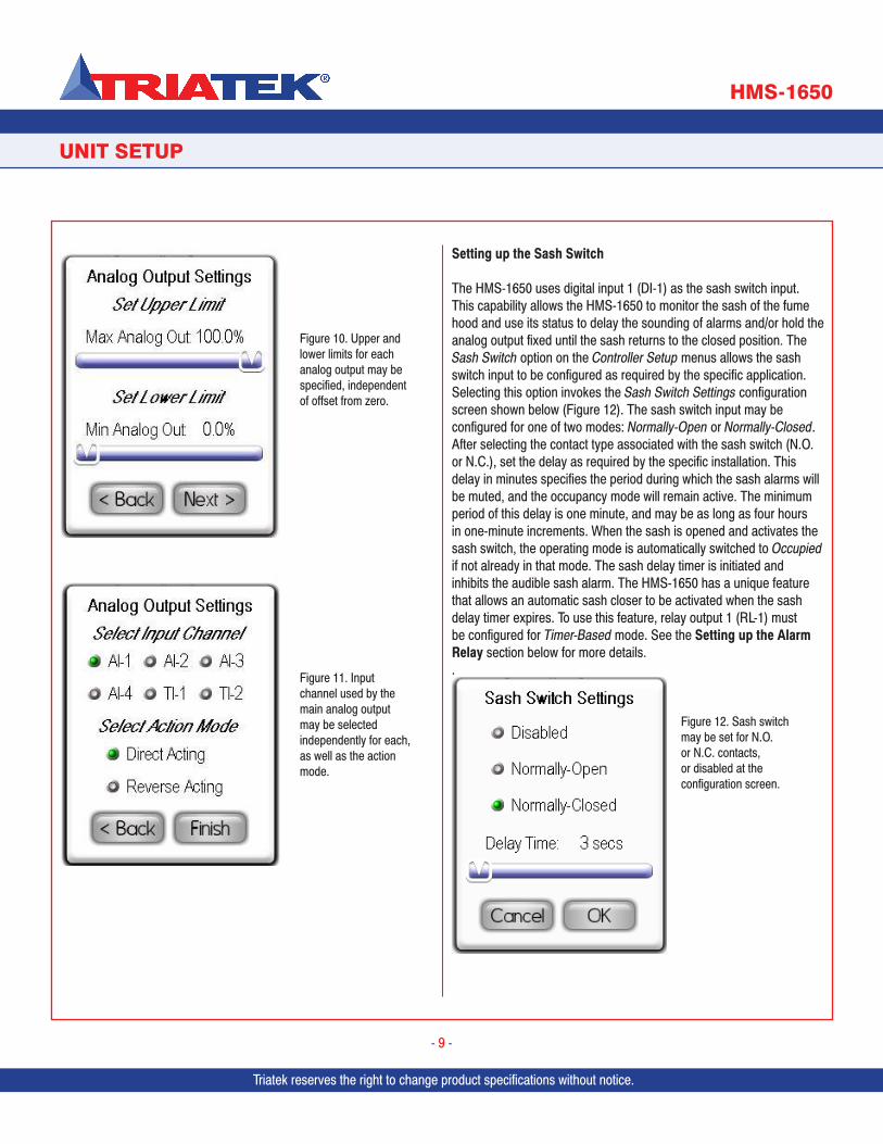
Once the operating mode and output range have been specified, the next Analog Output Setup configuration screen prompts the user to specify the minimum and maximum limits for the analog output in percentage (Figure 10). The default minimum and maximum are zero and 100 percent, respectively. This prevents the analog output from exceeding or going below a predetermined voltage or current output. Clicking the Next button invokes the last Analog Output Settings configuration screen (Figure 11), where the user can specify the analog input to which this analog output should be mapped, and select the action mode for the analog output. The default setting uses AI-1 (face velocity) as the analog input channel for the analog output (exhaust damper). The action mode determines the direction in which the output is driven based on the sensor input (AI-1), and defaults to Direct Acting.
Figure 9. Proportional (direct) and PID analog output modes are supported.
Figure 8. Engineering units and input signal range may be selected during configuration.
Triatek reserves the right to change product specifications without notice.
UNIT SETUP
HMS-1650
Triatek reserves the right to change product specifications without notice.
- 9 -
Setting up the Sash Switch
The HMS-1650 uses digital input 1 (DI-1) as the sash switch input. This capability allows the HMS-1650 to monitor the sash of the fume hood and use its status to delay the sounding of alarms and/or hold the analog output fixed until the sash returns to the closed position. The Sash Switch option on the Controller Setup menus allows the sash switch input to be configured as required by the specific application. Selecting this option invokes the Sash Switch Settings configuration screen shown below (Figure 12). The sash switch input may be configured for one of two modes: Normally-Open or Normally-Closed. After selecting the contact type associated with the sash switch (N.O. or N.C.), set the delay as required by the specific installation. This delay in minutes specifies the period during which the sash alarms will be muted, and the occupancy mode will remain active. The minimum period of this delay is one minute, and may be as long as four hours in one-minute increments. When the sash is opened and activates the sash switch, the operating mode is automatically switched to Occupied if not already in that mode. The sash delay timer is initiated and inhibits the audible sash alarm. The HMS-1650 has a unique feature that allows an automatic sash closer to be activated when the sash delay timer expires. To use this feature, relay output 1 (RL-1) must be configured for Timer-Based mode. See the Setting up the Alarm Relay section below for more details..
Figure 10. Upper and lower limits for each analog output may be specified, independent of offset from zero.
Figure 11. Input channel used by the main analog output may be selected independently for each, as well as the action mode.
Figure 12. Sash switch may be set for N.O. or N.C. contacts, or disabled at the configuration screen.
Triatek reserves the right to change product specifications without notice. Triatek reserves the right to change product specifications without notice.
UNIT SETUP
HMS-1650
Triatek reserves the right to change product specifications without notice.
- 10 -
Setting up the Alarm Relay
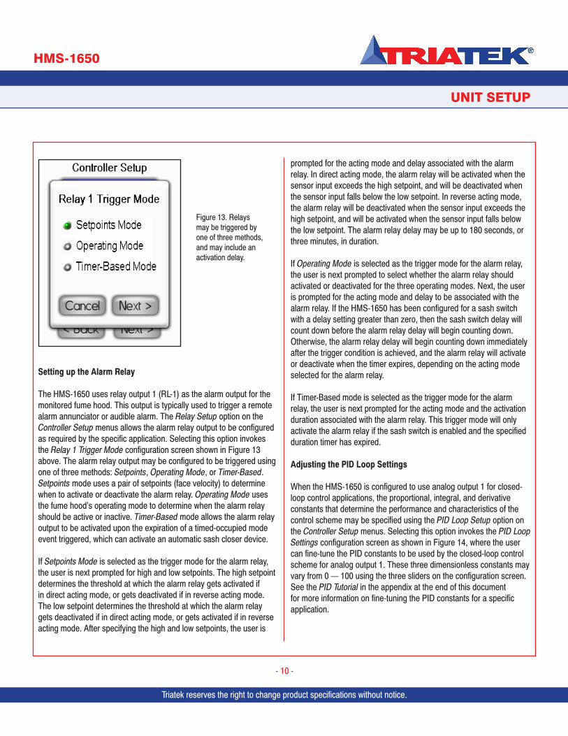
The HMS-1650 uses relay output 1 (RL-1) as the alarm output for the monitored fume hood. This output is typically used to trigger a remote alarm annunciator or audible alarm. The Relay Setup option on the Controller Setup menus allows the alarm relay output to be configured as required by the specific application. Selecting this option invokes the Relay 1 Trigger Mode configuration screen shown in Figure 13 above. The alarm relay output may be configured to be triggered using one of three methods: Setpoints, Operating Mode, or Timer-Based. Setpoints mode uses a pair of setpoints (face velocity) to determine when to activate or deactivate the alarm relay. Operating Mode uses the fume hood’s operating mode to determine when the alarm relay should be active or inactive. Timer-Based mode allows the alarm relay output to be activated upon the expiration of a timed-occupied mode event triggered, which can activate an automatic sash closer device.
If Setpoints Mode is selected as the trigger mode for the alarm relay, the user is next prompted for high and low setpoints. The high setpoint determines the threshold at which the alarm relay gets activated if in direct acting mode, or gets deactivated if in reverse acting mode. The low setpoint determines the threshold at which the alarm relay gets deactivated if in direct acting mode, or gets activated if in reverse acting mode. After specifying the high and low setpoints, the user is
prompted for the acting mode and delay associated with the alarm relay. In direct acting mode, the alarm relay will be activated when the sensor input exceeds the high setpoint, and will be deactivated when the sensor input falls below the low setpoint. In reverse acting mode, the alarm relay will be deactivated when the sensor input exceeds the high setpoint, and will be activated when the sensor input falls below the low setpoint. The alarm relay delay may be up to 180 seconds, or three minutes, in duration.
If Operating Mode is selected as the trigger mode for the alarm relay, the user is next prompted to select whether the alarm relay should activated or deactivated for the three operating modes. Next, the user is prompted for the acting mode and delay to be associated with the alarm relay. If the HMS-1650 has been configured for a sash switch with a delay setting greater than zero, then the sash switch delay will count down before the alarm relay delay will begin counting down. Otherwise, the alarm relay delay will begin counting down immediately after the trigger condition is achieved, and the alarm relay will activate or deactivate when the timer expires, depending on the acting mode selected for the alarm relay.
If Timer-Based mode is selected as the trigger mode for the alarm relay, the user is next prompted for the acting mode and the activation duration associated with the alarm relay. This trigger mode will only activate the alarm relay if the sash switch is enabled and the specified duration timer has expired.
Adjusting the PID Loop Settings
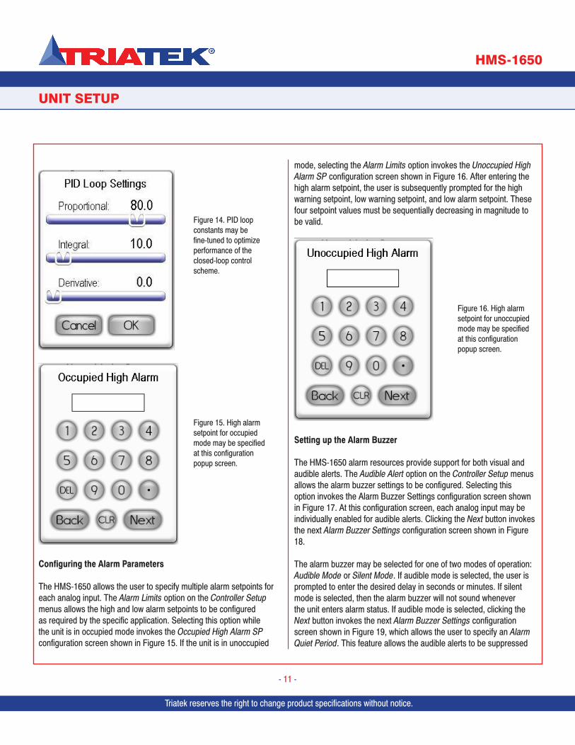
When the HMS-1650 is configured to use analog output 1 for closed-loop control applications, the proportional, integral, and derivative constants that determine the performance and characteristics of the control scheme may be specified using the PID Loop Setup option on the Controller Setup menus. Selecting this option invokes the PID Loop Settings configuration screen as shown in Figure 14, where the user can fine-tune the PID constants to be used by the closed-loop control scheme for analog output 1. These three dimensionless constants may vary from 0 — 100 using the three sliders on the configuration screen. See the PID Tutorial in the appendix at the end of this document for more information on fine-tuning the PID constants for a specific application.
Figure 13. Relays may be triggered by one of three methods, and may include an activation delay.
Triatek reserves the right to change product specifications without notice.
UNIT SETUP
HMS-1650
Triatek reserves the right to change product specifications without notice.
- 11 -
Configuring the Alarm Parameters
The HMS-1650 allows the user to specify multiple alarm setpoints for each analog input. The Alarm Limits option on the Controller Setup menus allows the high and low alarm setpoints to be configured as required by the specific application. Selecting this option while the unit is in occupied mode invokes the Occupied High Alarm SP configuration screen shown in Figure 15. If the unit is in unoccupied
mode, selecting the Alarm Limits option invokes the Unoccupied High Alarm SP configuration screen shown in Figure 16. After entering the high alarm setpoint, the user is subsequently prompted for the high warning setpoint, low warning setpoint, and low alarm setpoint. These four setpoint values must be sequentially decreasing in magnitude to be valid.
Setting up the Alarm Buzzer
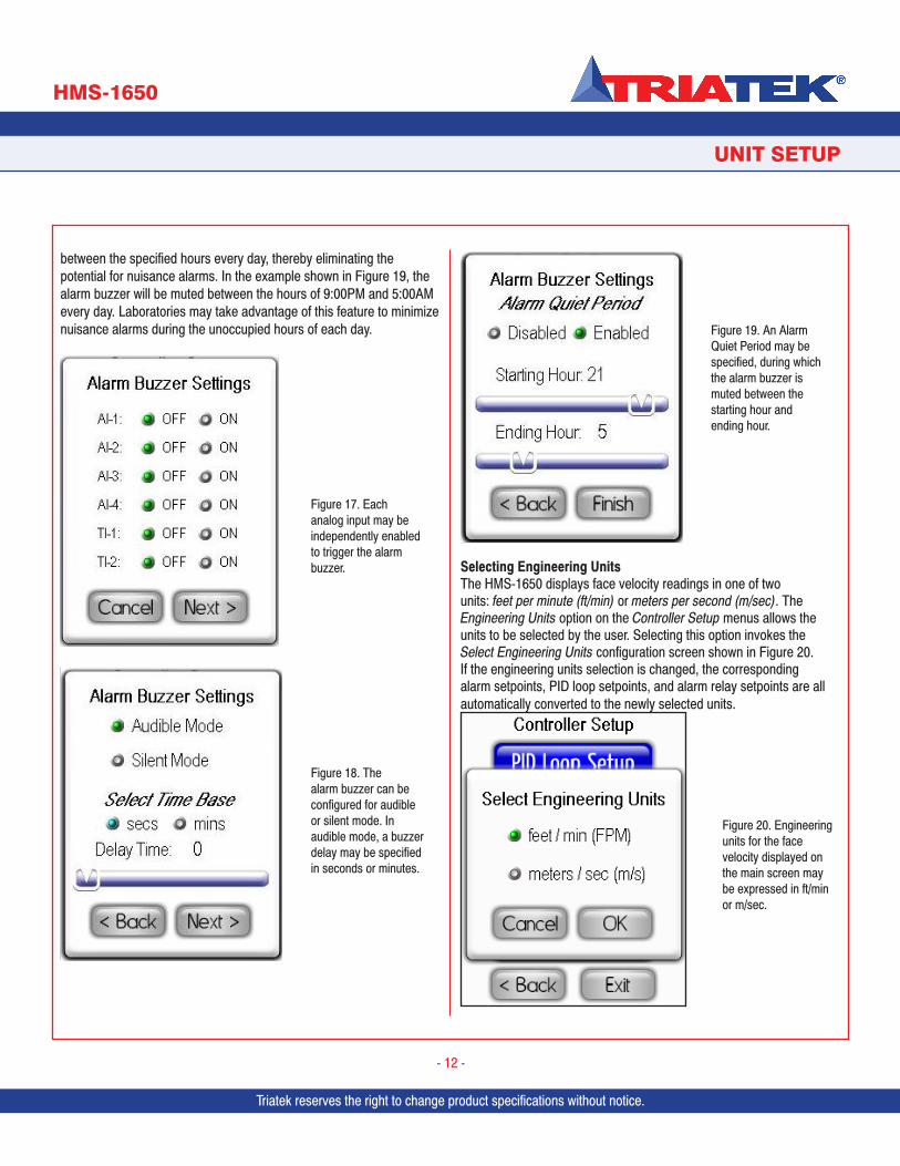
The HMS-1650 alarm resources provide support for both visual and audible alerts. The Audible Alert option on the Controller Setup menus allows the alarm buzzer settings to be configured. Selecting this option invokes the Alarm Buzzer Settings configuration screen shown in Figure 17. At this configuration screen, each analog input may be individually enabled for audible alerts. Clicking the Next button invokes the next Alarm Buzzer Settings configuration screen shown in Figure 18.
The alarm buzzer may be selected for one of two modes of operation: Audible Mode or Silent Mode. If audible mode is selected, the user is prompted to enter the desired delay in seconds or minutes. If silent mode is selected, then the alarm buzzer will not sound whenever the unit enters alarm status. If audible mode is selected, clicking the Next button invokes the next Alarm Buzzer Settings configuration screen shown in Figure 19, which allows the user to specify an Alarm Quiet Period. This feature allows the audible alerts to be suppressed
Figure 16. High alarm setpoint for unoccupied mode may be specified at this configuration popup screen.
Figure 14. PID loop constants may be fine-tuned to optimize performance of the closed-loop control scheme.
Figure 15. High alarm setpoint for occupied mode may be specified at this configuration popup screen.
Triatek reserves the right to change product specifications without notice. Triatek reserves the right to change product specifications without notice.
UNIT SETUP
HMS-1650
Triatek reserves the right to change product specifications without notice.
- 12 -
between the specified hours every day, thereby eliminating the potential for nuisance alarms. In the example shown in Figure 19, the alarm buzzer will be muted between the hours of 9:00PM and 5:00AM every day. Laboratories may take advantage of this feature to minimize nuisance alarms during the unoccupied hours of each day.
Selecting Engineering UnitsThe HMS-1650 displays face velocity readings in one of two units: feet per minute (ft/min) or meters per second (m/sec). The Engineering Units option on the Controller Setup menus allows the units to be selected by the user. Selecting this option invokes the Select Engineering Units configuration screen shown in Figure 20. If the engineering units selection is changed, the corresponding alarm setpoints, PID loop setpoints, and alarm relay setpoints are all automatically converted to the newly selected units.
Figure 17. Each analog input may be independently enabled to trigger the alarm buzzer.
Figure 18. The alarm buzzer can be configured for audible or silent mode. In audible mode, a buzzer delay may be specified in seconds or minutes.
Figure 19. An Alarm Quiet Period may be specified, during which the alarm buzzer is muted between the starting hour and ending hour.
Figure 20. Engineering units for the face velocity displayed on the main screen may be expressed in ft/min or m/sec.
Triatek reserves the right to change product specifications without notice.
UNIT SETUP
HMS-1650
Triatek reserves the right to change product specifications without notice.
- 13 -
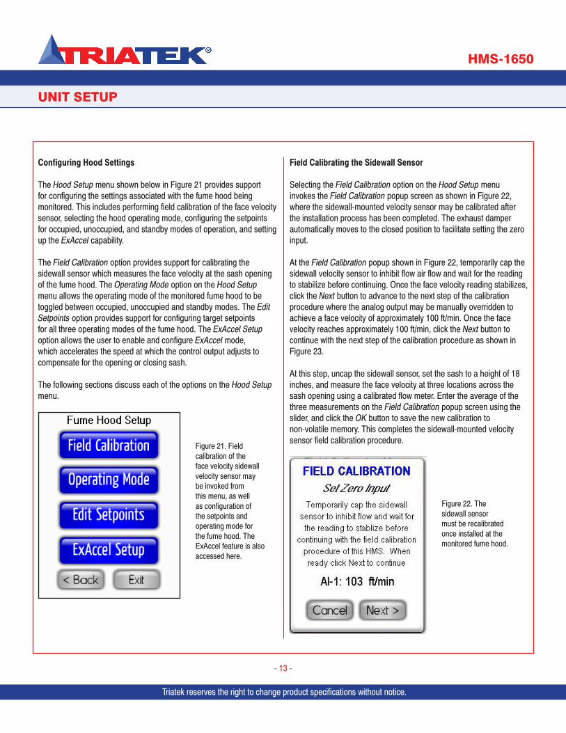
Configuring Hood Settings
The Hood Setup menu shown below in Figure 21 provides support for configuring the settings associated with the fume hood being monitored. This includes performing field calibration of the face velocity sensor, selecting the hood operating mode, configuring the setpoints for occupied, unoccupied, and standby modes of operation, and setting up the ExAccel capability.
The Field Calibration option provides support for calibrating the sidewall sensor which measures the face velocity at the sash opening of the fume hood. The Operating Mode option on the Hood Setup menu allows the operating mode of the monitored fume hood to be toggled between occupied, unoccupied and standby modes. The Edit Setpoints option provides support for configuring target setpoints for all three operating modes of the fume hood. The ExAccel Setup option allows the user to enable and configure ExAccel mode, which accelerates the speed at which the control output adjusts to compensate for the opening or closing sash.
The following sections discuss each of the options on the Hood Setup menu.
Field Calibrating the Sidewall Sensor
Selecting the Field Calibration option on the Hood Setup menu invokes the Field Calibration popup screen as shown in Figure 22, where the sidewall-mounted velocity sensor may be calibrated after the installation process has been completed. The exhaust damper automatically moves to the closed position to facilitate setting the zero input.
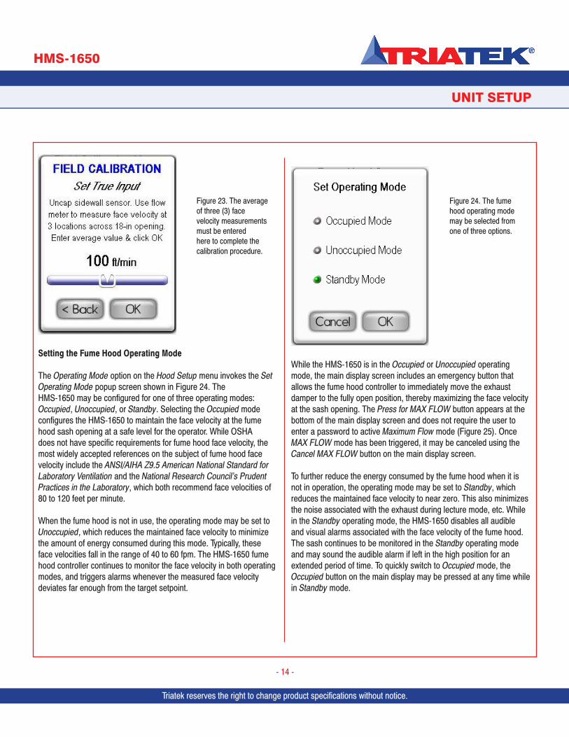
At the Field Calibration popup shown in Figure 22, temporarily cap the sidewall velocity sensor to inhibit flow air flow and wait for the reading to stabilize before continuing. Once the face velocity reading stabilizes, click the Next button to advance to the next step of the calibration procedure where the analog output may be manually overridden to achieve a face velocity of approximately 100 ft/min. Once the face velocity reaches approximately 100 ft/min, click the Next button to continue with the next step of the calibration procedure as shown in Figure 23.
At this step, uncap the sidewall sensor, set the sash to a height of 18 inches, and measure the face velocity at three locations across the sash opening using a calibrated flow meter. Enter the average of the three measurements on the Field Calibration popup screen using the slider, and click the OK button to save the new calibration to non-volatile memory. This completes the sidewall-mounted velocity sensor field calibration procedure.
Figure 21. Field calibration of the face velocity sidewall velocity sensor may be invoked from this menu, as well as configuration of the setpoints and operating mode for the fume hood. The ExAccel feature is also accessed here.
Figure 22. The sidewall sensor must be recalibrated once installed at the monitored fume hood.
Triatek reserves the right to change product specifications without notice. Triatek reserves the right to change product specifications without notice.
UNIT SETUP
HMS-1650
Triatek reserves the right to change product specifications without notice.
- 14 -
Setting the Fume Hood Operating Mode
The Operating Mode option on the Hood Setup menu invokes the Set Operating Mode popup screen shown in Figure 24. The HMS-1650 may be configured for one of three operating modes: Occupied, Unoccupied, or Standby. Selecting the Occupied mode configures the HMS-1650 to maintain the face velocity at the fume hood sash opening at a safe level for the operator. While OSHA does not have specific requirements for fume hood face velocity, the most widely accepted references on the subject of fume hood face velocity include the ANSI/AIHA Z9.5 American National Standard for Laboratory Ventilation and the National Research Council’s Prudent Practices in the Laboratory, which both recommend face velocities of 80 to 120 feet per minute.
When the fume hood is not in use, the operating mode may be set to Unoccupied, which reduces the maintained face velocity to minimize the amount of energy consumed during this mode. Typically, these face velocities fall in the range of 40 to 60 fpm. The HMS-1650 fume hood controller continues to monitor the face velocity in both operating modes, and triggers alarms whenever the measured face velocity deviates far enough from the target setpoint.
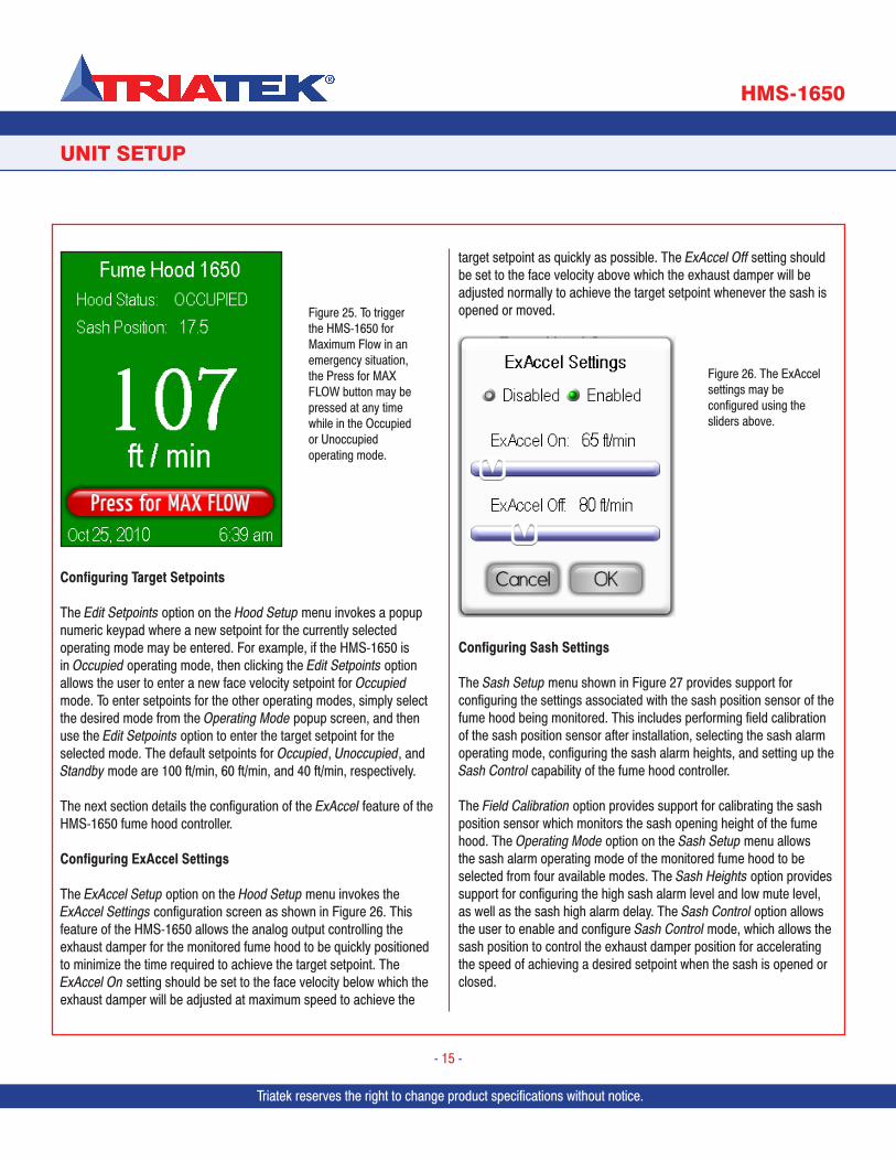
While the HMS-1650 is in the Occupied or Unoccupied operating mode, the main display screen includes an emergency button that allows the fume hood controller to immediately move the exhaust damper to the fully open position, thereby maximizing the face velocity at the sash opening. The Press for MAX FLOW button appears at the bottom of the main display screen and does not require the user to enter a password to active Maximum Flow mode (Figure 25). Once MAX FLOW mode has been triggered, it may be canceled using the Cancel MAX FLOW button on the main display screen.
To further reduce the energy consumed by the fume hood when it is not in operation, the operating mode may be set to Standby, which reduces the maintained face velocity to near zero. This also minimizes the noise associated with the exhaust during lecture mode, etc. While in the Standby operating mode, the HMS-1650 disables all audible and visual alarms associated with the face velocity of the fume hood. The sash continues to be monitored in the Standby operating mode and may sound the audible alarm if left in the high position for an extended period of time. To quickly switch to Occupied mode, the Occupied button on the main display may be pressed at any time while in Standby mode.
Figure 23. The average of three (3) face velocity measurements must be entered here to complete the calibration procedure.
Figure 24. The fume hood operating mode may be selected from one of three options.
Triatek reserves the right to change product specifications without notice.
UNIT SETUP
HMS-1650
Triatek reserves the right to change product specifications without notice.
- 15 -
Configuring Target Setpoints
The Edit Setpoints option on the Hood Setup menu invokes a popup numeric keypad where a new setpoint for the currently selected operating mode may be entered. For example, if the HMS-1650 is in Occupied operating mode, then clicking the Edit Setpoints option allows the user to enter a new face velocity setpoint for Occupied mode. To enter setpoints for the other operating modes, simply select the desired mode from the Operating Mode popup screen, and then use the Edit Setpoints option to enter the target setpoint for the selected mode. The default setpoints for Occupied, Unoccupied, and Standby mode are 100 ft/min, 60 ft/min, and 40 ft/min, respectively.
The next section details the configuration of the ExAccel feature of the HMS-1650 fume hood controller.
Configuring ExAccel Settings
The ExAccel Setup option on the Hood Setup menu invokes the ExAccel Settings configuration screen as shown in Figure 26. This feature of the HMS-1650 allows the analog output controlling the exhaust damper for the monitored fume hood to be quickly positioned to minimize the time required to achieve the target setpoint. The ExAccel On setting should be set to the face velocity below which the exhaust damper will be adjusted at maximum speed to achieve the
target setpoint as quickly as possible. The ExAccel Off setting should be set to the face velocity above which the exhaust damper will be adjusted normally to achieve the target setpoint whenever the sash is opened or moved.
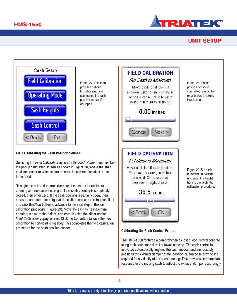
Configuring Sash Settings
The Sash Setup menu shown in Figure 27 provides support for configuring the settings associated with the sash position sensor of the fume hood being monitored. This includes performing field calibration of the sash position sensor after installation, selecting the sash alarm operating mode, configuring the sash alarm heights, and setting up the Sash Control capability of the fume hood controller.
The Field Calibration option provides support for calibrating the sash position sensor which monitors the sash opening height of the fume hood. The Operating Mode option on the Sash Setup menu allows the sash alarm operating mode of the monitored fume hood to be selected from four available modes. The Sash Heights option provides support for configuring the high sash alarm level and low mute level, as well as the sash high alarm delay. The Sash Control option allows the user to enable and configure Sash Control mode, which allows the sash position to control the exhaust damper position for accelerating the speed of achieving a desired setpoint when the sash is opened or closed.
Figure 26. The ExAccel settings may be configured using the sliders above.
Figure 25. To trigger the HMS-1650 for Maximum Flow in an emergency situation, the Press for MAX FLOW button may be pressed at any time while in the Occupied or Unoccupied operating mode.
Triatek reserves the right to change product specifications without notice. Triatek reserves the right to change product specifications without notice.
UNIT SETUP
HMS-1650
Triatek reserves the right to change product specifications without notice.
- 16 -
Field Calibrating the Sash Position Sensor
Selecting the Field Calibration option on the Sash Setup menu invokes the popup calibration screen as shown in Figure 28, where the sash position sensor may be calibrated once it has been installed at the fume hood.
To begin the calibration procedure, set the sash to its minimum opening and measure the height. If the sash opening is completely closed, then enter zero. If the sash opening is partially open, then measure and enter the height at the calibration screen using the slider and click the Next button to advance to the next step of the sash calibration procedure (Figure 29). Move the sash to its maximum opening, measure the height, and enter it using the slider on the Field Calibration popup screen. Click the OK button to save the new calibration to non-volatile memory. This completes the field calibration procedure for the sash position sensor.
Calibrating the Sash Control Feature
The HMS-1650 features a comprehensive closed-loop control scheme using both sash control and sidewall sensing. The sash control is activated automatically anytime the sash moves, and immediately positions the exhaust damper at the position calibrated to provide the required face velocity at the sash opening. This provides an immediate response to the moving sash to adjust the exhaust damper accordingly.
Figure 27. This menu provides options for calibrating and configuring the sash position sensor if equipped.
Figure 28. If sash position sensor is connected, it must be recalibrated following installation.
Figure 29. Set sash to maximum position and enter the height here to complete the calibration procedure.
Triatek reserves the right to change product specifications without notice.
Once the sash stops moving, the PID control loop resumes using the sidewall sensor to fine tune the face velocity to meet the target setpoint.
Selecting the Sash Control option on the Sash Setup menu invokes the sash width configuration screen, where the width of the sash opening may be specified in inches. This width is used in conjunction with the height of the sash opening to calculate the effective flow in cfm.After entering the sash width, click the Next button to advance to the first calibration screen where the sash should be moved to the closed position. Wait for the face velocity to stabilize near the current setpoint, and then click the Next button to advance to the next calibration screen. Move the sash to the quarter open position, wait for the face velocity to resume the target setpoint, and then click the Next button to advance to the next calibration screen. Move the sash to the half open position, wait for the face velocity to resume the target setpoint, and then click the Next button to advance to the next calibration screen. Move the sash to the three-quarter open position, wait for the face velocity to resume the target setpoint, and then click the Next button to advance to the next calibration screen. Move the sash to the full open position, wait for the face velocity to resume the target setpoint, and then click the Next button to invoke the calibration results screen.
Configuring Network Settings
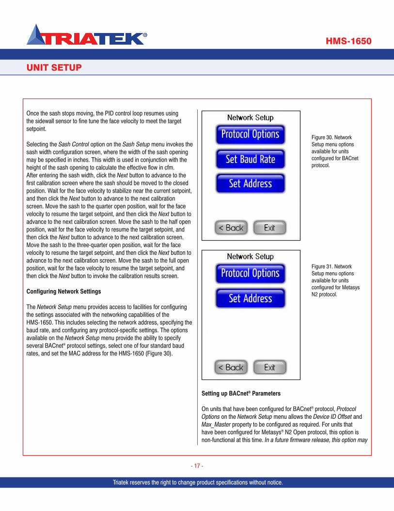
The Network Setup menu provides access to facilities for configuring the settings associated with the networking capabilities of the HMS-1650. This includes selecting the network address, specifying the baud rate, and configuring any protocol-specific settings. The options available on the Network Setup menu provide the ability to specify several BACnet® protocol settings, select one of four standard baud rates, and set the MAC address for the HMS-1650 (Figure 30).
Setting up BACnet® Parameters
On units that have been configured for BACnet® protocol, Protocol Options on the Network Setup menu allows the Device ID Offset and Max_Master property to be configured as required. For units that have been configured for Metasys® N2 Open protocol, this option is non-functional at this time. In a future firmware release, this option may
UNIT SETUP
HMS-1650
Triatek reserves the right to change product specifications without notice.
- 17 -
Figure 30. Network Setup menu options available for units configured for BACnet protocol.
Figure 31. Network Setup menu options available for units configured for Metasys N2 protocol.
Triatek reserves the right to change product specifications without notice. Triatek reserves the right to change product specifications without notice.
allow users to configure specific settings associated with the N2 Open protocol.
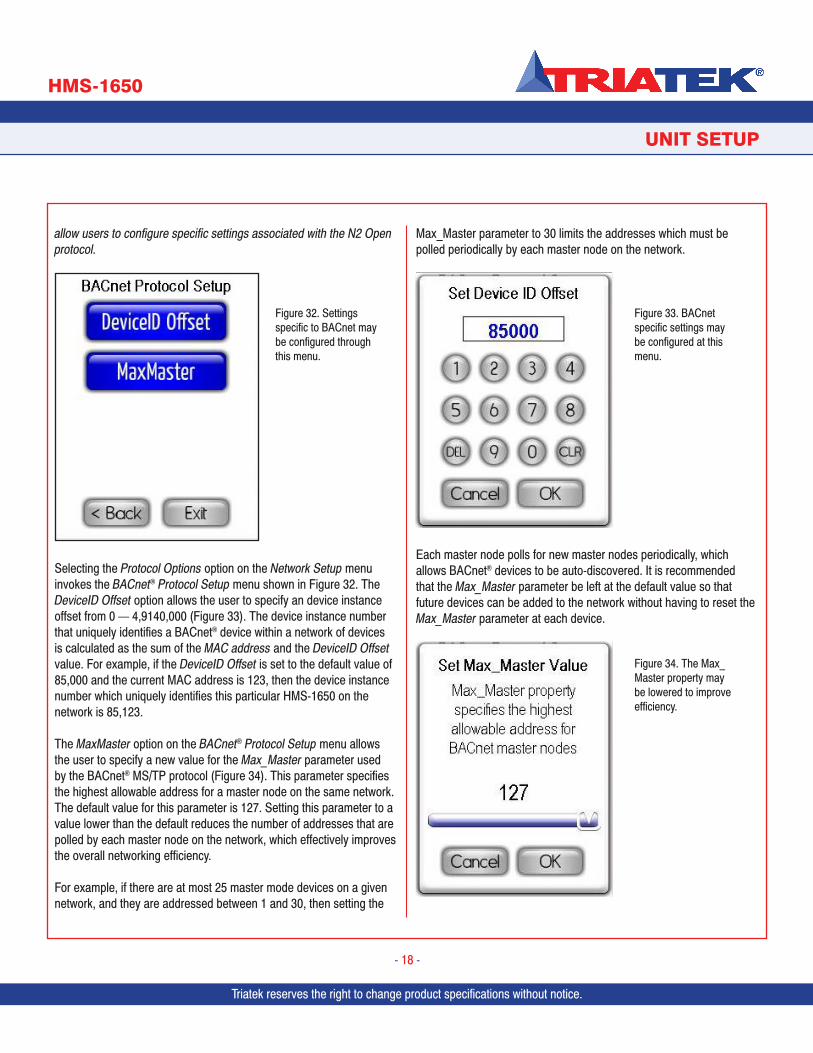
Selecting the Protocol Options option on the Network Setup menu invokes the BACnet® Protocol Setup menu shown in Figure 32. The DeviceID Offset option allows the user to specify an device instance offset from 0 — 4,9140,000 (Figure 33). The device instance number that uniquely identifies a BACnet® device within a network of devices is calculated as the sum of the MAC address and the DeviceID Offset value. For example, if the DeviceID Offset is set to the default value of 85,000 and the current MAC address is 123, then the device instance number which uniquely identifies this particular HMS-1650 on the network is 85,123.
The MaxMaster option on the BACnet® Protocol Setup menu allows the user to specify a new value for the Max_Master parameter used by the BACnet® MS/TP protocol (Figure 34). This parameter specifies the highest allowable address for a master node on the same network. The default value for this parameter is 127. Setting this parameter to a value lower than the default reduces the number of addresses that are polled by each master node on the network, which effectively improves the overall networking efficiency.
For example, if there are at most 25 master mode devices on a given network, and they are addressed between 1 and 30, then setting the
Max_Master parameter to 30 limits the addresses which must be polled periodically by each master node on the network.
Each master node polls for new master nodes periodically, which allows BACnet® devices to be auto-discovered. It is recommended that the Max_Master parameter be left at the default value so that future devices can be added to the network without having to reset the Max_Master parameter at each device.
UNIT SETUP
HMS-1650
Triatek reserves the right to change product specifications without notice.
- 18 -
Figure 32. Settings specific to BACnet may be configured through this menu.
Figure 33. BACnet specific settings may be configured at this menu.
Figure 34. The Max_Master property may be lowered to improve efficiency.
Triatek reserves the right to change product specifications without notice.
UNIT SETUP
HMS-1650
Triatek reserves the right to change product specifications without notice.
- 19 -
The Object List and Properties options on the BACnet® Protocol Setup menu allow the user to display the list of BACnet® objects and their properties, respectively. These menu options are currently disabled, but will be enabled in a future firmware release for the HMS-1650.
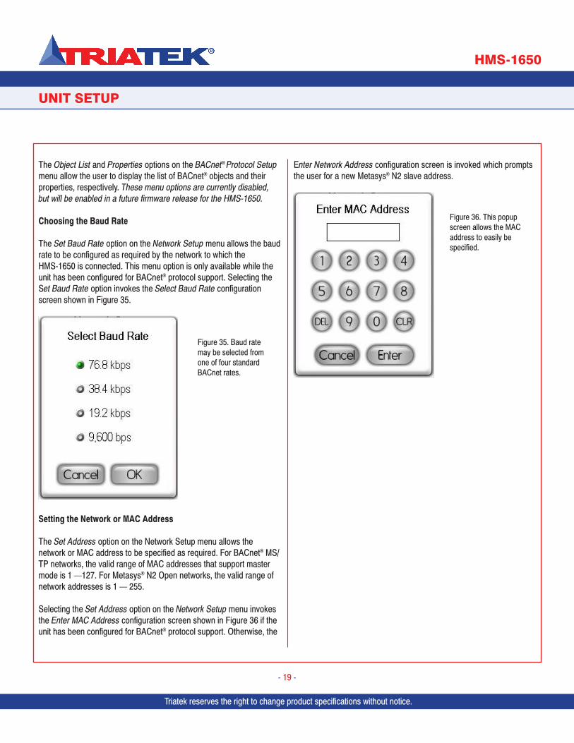
Choosing the Baud Rate
The Set Baud Rate option on the Network Setup menu allows the baud rate to be configured as required by the network to which the HMS-1650 is connected. This menu option is only available while the unit has been configured for BACnet® protocol support. Selecting the Set Baud Rate option invokes the Select Baud Rate configuration screen shown in Figure 35.
Setting the Network or MAC Address
The Set Address option on the Network Setup menu allows the network or MAC address to be specified as required. For BACnet® MS/TP networks, the valid range of MAC addresses that support master mode is 1 —127. For Metasys® N2 Open networks, the valid range of network addresses is 1 — 255.
Selecting the Set Address option on the Network Setup menu invokes the Enter MAC Address configuration screen shown in Figure 36 if the unit has been configured for BACnet® protocol support. Otherwise, the
Enter Network Address configuration screen is invoked which prompts the user for a new Metasys® N2 slave address.
Figure 35. Baud rate may be selected from one of four standard BACnet rates.
Figure 36. This popup screen allows the MAC address to easily be specified.
Triatek reserves the right to change product specifications without notice. Triatek reserves the right to change product specifications without notice.
SYSTEM SETUP
HMS-1650
Triatek reserves the right to change product specifications without notice.
- 20 -
Configuring Secondary Analog Inputs
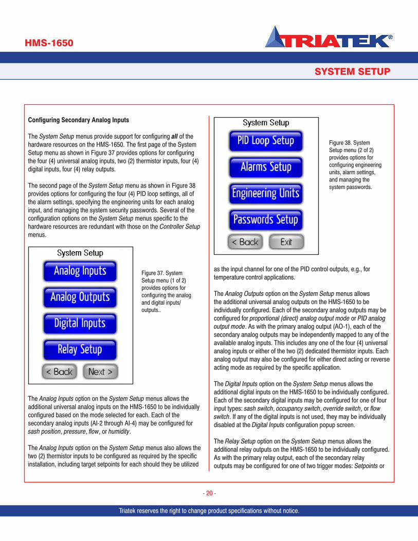
The System Setup menus provide support for configuring all of the hardware resources on the HMS-1650. The first page of the System Setup menu as shown in Figure 37 provides options for configuring the four (4) universal analog inputs, two (2) thermistor inputs, four (4) digital inputs, four (4) relay outputs.
The second page of the System Setup menu as shown in Figure 38 provides options for configuring the four (4) PID loop settings, all of the alarm settings, specifying the engineering units for each analog input, and managing the system security passwords. Several of the configuration options on the System Setup menus specific to the hardware resources are redundant with those on the Controller Setup menus.
The Analog Inputs option on the System Setup menus allows the additional universal analog inputs on the HMS-1650 to be individually configured based on the mode selected for each. Each of the secondary analog inputs (AI-2 through AI-4) may be configured for sash position, pressure, flow, or humidity.
The Analog Inputs option on the System Setup menus also allows the two (2) thermistor inputs to be configured as required by the specific installation, including target setpoints for each should they be utilized
as the input channel for one of the PID control outputs, e.g., for temperature control applications.
The Analog Outputs option on the System Setup menus allows the additional universal analog outputs on the HMS-1650 to be individually configured. Each of the secondary analog outputs may be configured for proportional (direct) analog output mode or PID analog output mode. As with the primary analog output (AO-1), each of the secondary analog outputs may be independently mapped to any of the available analog inputs. This includes any one of the four (4) universal analog inputs or either of the two (2) dedicated thermistor inputs. Each analog output may also be configured for either direct acting or reverse acting mode as required by the specific application.
The Digital Inputs option on the System Setup menus allows the additional digital inputs on the HMS-1650 to be individually configured. Each of the secondary digital inputs may be configured for one of four input types: sash switch, occupancy switch, override switch, or flow switch. If any of the digital inputs is not used, they may be individually disabled at the Digital Inputs configuration popup screen.
The Relay Setup option on the System Setup menus allows the additional relay outputs on the HMS-1650 to be individually configured. As with the primary relay output, each of the secondary relay outputs may be configured for one of two trigger modes: Setpoints or
Figure 37. System Setup menu (1 of 2) provides options for configuring the analog and digital inputs/outputs..
Figure 38. System Setup menu (2 of 2) provides options for configuring engineering units, alarm settings, and managing the system passwords.
Triatek reserves the right to change product specifications without notice.
SYSTEM SETUP
HMS-1650
Triatek reserves the right to change product specifications without notice.
- 21 -
Operating Mode. Setpoints Mode uses a pair of setpoints to determine when to activate or deactivate the alarm relay. Operating Mode uses the operating mode of the fume hood to determine when the alarm relay should be active or inactive.
The PID Loop Setup option on the System Setup menus allows the additional PID control loops to be individually configured based on the requirements of the specific application. Each of the secondary PID control loops is directly associated with the corresponding secondary analog output. As with the primary PID loop settings, the three constants (proportional, integral, derivative) may be independently tuned for the desired response at each analog output.
The Alarms Setup option on the System Setup menus allows all of the settings associated with the alarm functionality of the HMS-1650 to be configured independently. This includes all of the individual alarm enables, alarm setpoints, and alarm buzzer enables. The flexibility of the alarm capabilities incorporated in the HMS-1650 is unmatched in the industry, and can be tailored to meet most any specification requirements.
The Engineering Units option on the System Setup menus allows the user to select between Imperial and Metric units for each analog input resource, including the two thermistor inputs. The default selection is Imperial units for all analog inputs.
The Passwords Setup option on the System Setup menus allows the user to manage the system security password facility that has been incorporated into the HMS-1650. Up to ten (10) unique multiple access level passwords may be stored in the unit to prevent unauthorized access to the system menus and configuration settings.
Configuring Secondary Analog Inputs
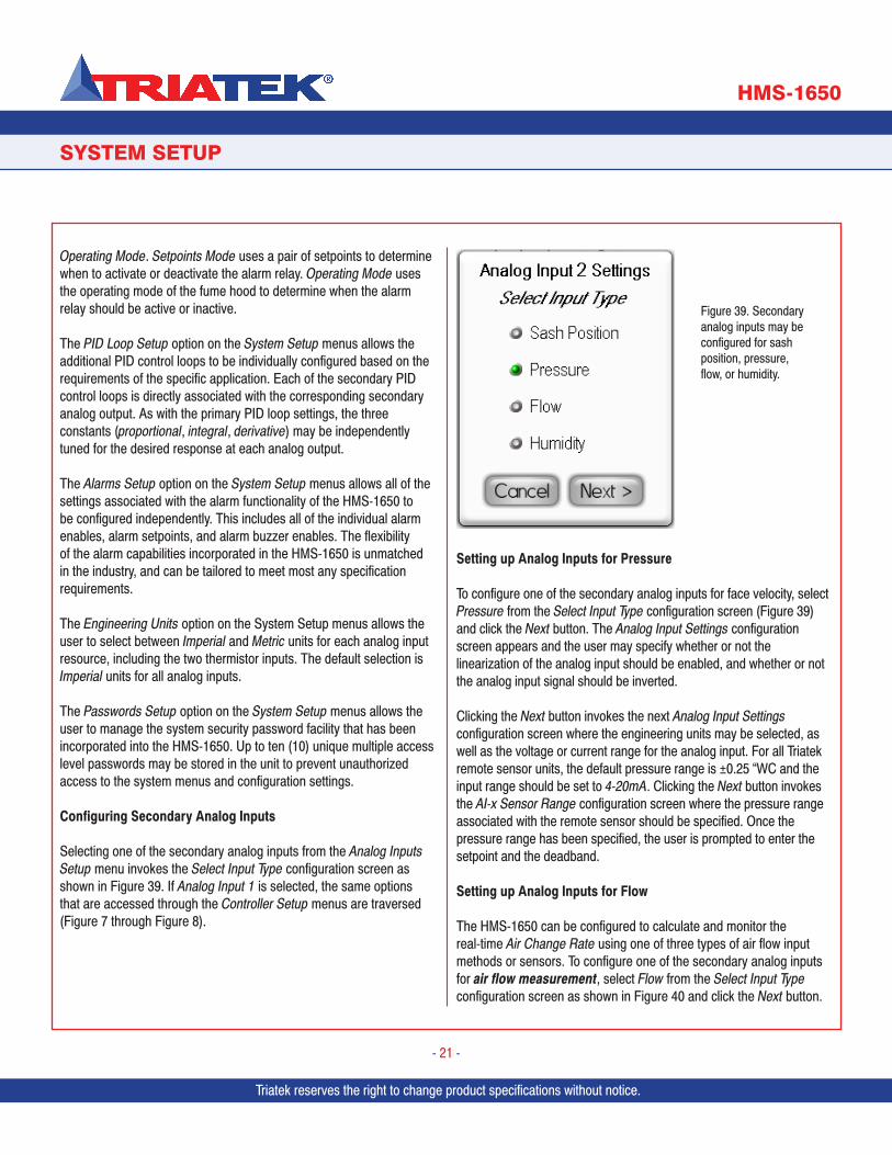
Selecting one of the secondary analog inputs from the Analog Inputs Setup menu invokes the Select Input Type configuration screen as shown in Figure 39. If Analog Input 1 is selected, the same options that are accessed through the Controller Setup menus are traversed (Figure 7 through Figure 8).
Setting up Analog Inputs for Pressure
To configure one of the secondary analog inputs for face velocity, select Pressure from the Select Input Type configuration screen (Figure 39) and click the Next button. The Analog Input Settings configuration screen appears and the user may specify whether or not the linearization of the analog input should be enabled, and whether or not the analog input signal should be inverted.
Clicking the Next button invokes the next Analog Input Settings configuration screen where the engineering units may be selected, as well as the voltage or current range for the analog input. For all Triatek remote sensor units, the default pressure range is ±0.25 “WC and the input range should be set to 4-20mA. Clicking the Next button invokes the AI-x Sensor Range configuration screen where the pressure range associated with the remote sensor should be specified. Once the pressure range has been specified, the user is prompted to enter the setpoint and the deadband.
Setting up Analog Inputs for Flow
The HMS-1650 can be configured to calculate and monitor the real-time Air Change Rate using one of three types of air flow input methods or sensors. To configure one of the secondary analog inputs for air flow measurement, select Flow from the Select Input Type configuration screen as shown in Figure 40 and click the Next button.
Figure 39. Secondary analog inputs may be configured for sash position, pressure, flow, or humidity.

Triatek reserves the right to change product specifications without notice. Triatek reserves the right to change product specifications without notice.
SYSTEM SETUP
HMS-1650
Triatek reserves the right to change product specifications without notice.
- 22 -
The Flow Sensor Input configuration screen shown in Figure 41 appears, allowing the user to select which type of sensor will be used for measuring air flow.
After selecting the type of sensor that is being used to measure air flow, clicking the Next button invokes two configuration screens (Figure 42) which allow the user to specify the minimum and maximum flows supported by the sensor. These values should be entered in the engineering units which correspond to the type of sensor. For example, the units would be either inches of water column (“WC) or Pascals (Pa) for DP transmitters.
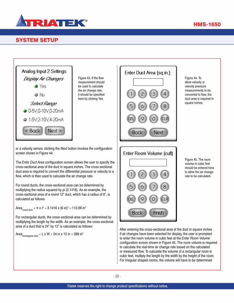
After specifying the air flow range for the sensor, clicking the Next button invokes the Analog Input x Settings configuration screen as shown in Figure 43, where the user may specify whether or not air changes should be calculated and displayed on the main screen, as well as the range of the input signal (voltage or current) for the air flow sensor. If air changes have been selected for display and the flow measurement device is either a differential pressure (DP) transmitter
Figure 40. To calculate & display air change rate, input should be configured for flow.
Figure 41. HMS-1650 supports three types of sensors for Air Flow measurement.
Figure 42. The minimum and maximum flow should be entered here from data found on the datasheet for the flow measurement device.
Triatek reserves the right to change product specifications without notice.
SYSTEM SETUP
HMS-1650
Triatek reserves the right to change product specifications without notice.
- 23 -
or a velocity sensor, clicking the Next button invokes the configuration screen shown in Figure 44.
The Enter Duct Area configuration screen allows the user to specify the cross-sectional area of the duct in square inches. The cross-sectional duct area is required to convert the differential pressure or velocity to a flow, which is then used to calculate the air change rate.
For round ducts, the cross-sectional area can be determined by multiplying the radius squared by pi (3.1416). As an example, the cross-sectional area of a round 12” duct, which has a radius of 6”, is calculated as follows:
Arearound duct = π x r2 = 3.1416 x (6 in)2 = 113.09 in2
For rectangular ducts, the cross-sectional area can be determined by multiplying the length by the width. As an example, the cross-sectional area of a duct that is 24” by 12” is calculated as follows:
Arearectangular duct = L x W = 24 in x 12 in = 288 in2 After entering the cross-sectional area of the duct in square inches if air changes have been selected for display, the user is prompted to enter the room volume in cubic feet at the Enter Room Volume configuration screen shown in Figure 45. The room volume is required to calculate the real-time air change rate based on the calculated or measured flow. To calculate the volume of a rectangular room in cubic feet, multiply the length by the width by the height of the room. For irregular shaped rooms, the volume will have to be determined
Figure 43. If the flow measurement should be used to calculate the air change rate, it should be specified here by clicking Yes.
Figure 44. To allow velocity or velocity pressure measurements to be converted to flow, the duct area is required in square inches.
Figure 45. The room volume in cubic feet should be entered here to allow the air change rate to be calculated.
Triatek reserves the right to change product specifications without notice. Triatek reserves the right to change product specifications without notice.
SYSTEM SETUP
HMS-1650
Triatek reserves the right to change product specifications without notice.
- 24 -
by breaking the room up into multiple smaller rectangular areas and summing the individual volumes to calculate the total room volume in cubic feet.
If air changes have been selected for display and the flow measurement device is an actual air flow sensor, then clicking the Next button invokes the configuration screen shown in Figure 45, which allows the user to specify the volume of the room being monitored. The room volume is required to calculate the air change rate.
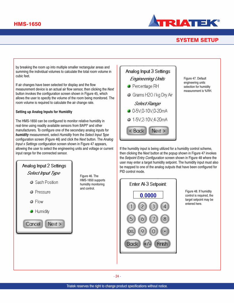
Setting up Analog Inputs for Humidity
The HMS-1650 can be configured to monitor relative humidity in real-time using readily available sensors from BAPI® and other manufacturers. To configure one of the secondary analog inputs for humidity measurement, select Humidity from the Select Input Type configuration screen (Figure 46) and click the Next button. The Analog Input x Settings configuration screen shown in Figure 47 appears, allowing the user to select the engineering units and voltage or current input range for the connected sensor.
If the humidity input is being utilized for a humidity control scheme, then clicking the Next button at the popup shown in Figure 47 invokes the Setpoint Entry Configuration screen shown in Figure 48 where the user may enter a target humidity setpoint. The humidity input must also be mapped to one of the analog outputs that have been configured for PID control mode.
Figure 46. The HMS-1650 supports humidity monitoring and control.
Figure 47. Default engineering units selection for humidity measurement is %RH.
Figure 48. If humidity control is required, the target setpoint may be entered here.
Triatek reserves the right to change product specifications without notice.
SYSTEM SETUP
HMS-1650
Triatek reserves the right to change product specifications without notice.
- 25 -
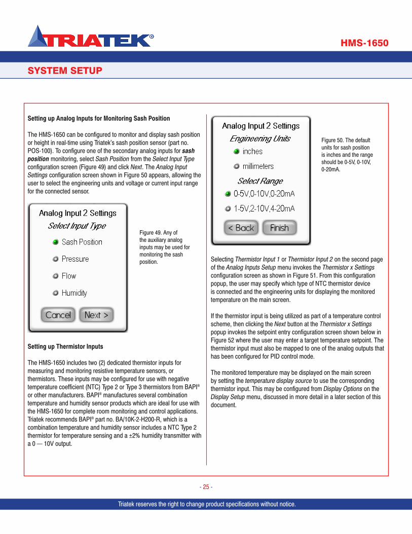
Setting up Analog Inputs for Monitoring Sash Position
The HMS-1650 can be configured to monitor and display sash position or height in real-time using Triatek’s sash position sensor (part no. POS-100). To configure one of the secondary analog inputs for sash position monitoring, select Sash Position from the Select Input Type configuration screen (Figure 49) and click Next. The Analog Input Settings configuration screen shown in Figure 50 appears, allowing the user to select the engineering units and voltage or current input range for the connected sensor.
Setting up Thermistor Inputs
The HMS-1650 includes two (2) dedicated thermistor inputs for measuring and monitoring resistive temperature sensors, or thermistors. These inputs may be configured for use with negative temperature coefficient (NTC) Type 2 or Type 3 thermistors from BAPI® or other manufacturers. BAPI® manufactures several combination temperature and humidity sensor products which are ideal for use with the HMS-1650 for complete room monitoring and control applications. Triatek recommends BAPI® part no. BA/10K-2-H200-R, which is a combination temperature and humidity sensor includes a NTC Type 2 thermistor for temperature sensing and a ±2% humidity transmitter with a 0 — 10V output.
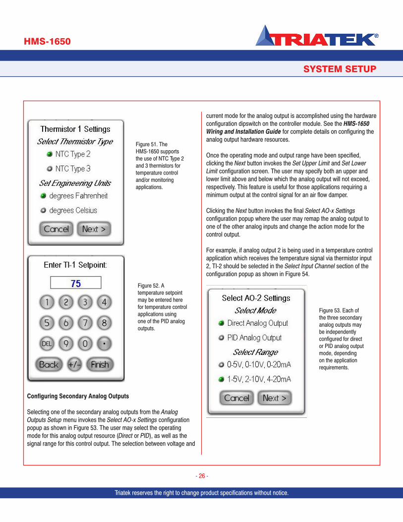
Selecting Thermistor Input 1 or Thermistor Input 2 on the second page of the Analog Inputs Setup menu invokes the Thermistor x Settings configuration screen as shown in Figure 51. From this configuration popup, the user may specify which type of NTC thermistor device is connected and the engineering units for displaying the monitored temperature on the main screen.
If the thermistor input is being utilized as part of a temperature control scheme, then clicking the Next button at the Thermistor x Settings popup invokes the setpoint entry configuration screen shown below in Figure 52 where the user may enter a target temperature setpoint. The thermistor input must also be mapped to one of the analog outputs that has been configured for PID control mode.
The monitored temperature may be displayed on the main screen by setting the temperature display source to use the corresponding thermistor input. This may be configured from Display Options on the Display Setup menu, discussed in more detail in a later section of this document.
Figure 49. Any of the auxiliary analog inputs may be used for monitoring the sash position.
Figure 50. The default units for sash position is inches and the range should be 0-5V, 0-10V, 0-20mA.
Triatek reserves the right to change product specifications without notice. Triatek reserves the right to change product specifications without notice.
SYSTEM SETUP
HMS-1650
Triatek reserves the right to change product specifications without notice.
- 26 -
Configuring Secondary Analog Outputs
Selecting one of the secondary analog outputs from the Analog Outputs Setup menu invokes the Select AO-x Settings configuration popup as shown in Figure 53. The user may select the operating mode for this analog output resource (Direct or PID), as well as the signal range for this control output. The selection between voltage and
current mode for the analog output is accomplished using the hardware configuration dipswitch on the controller module. See the HMS-1650 Wiring and Installation Guide for complete details on configuring the analog output hardware resources.
Once the operating mode and output range have been specified, clicking the Next button invokes the Set Upper Limit and Set Lower Limit configuration screen. The user may specify both an upper and lower limit above and below which the analog output will not exceed, respectively. This feature is useful for those applications requiring a minimum output at the control signal for an air flow damper.
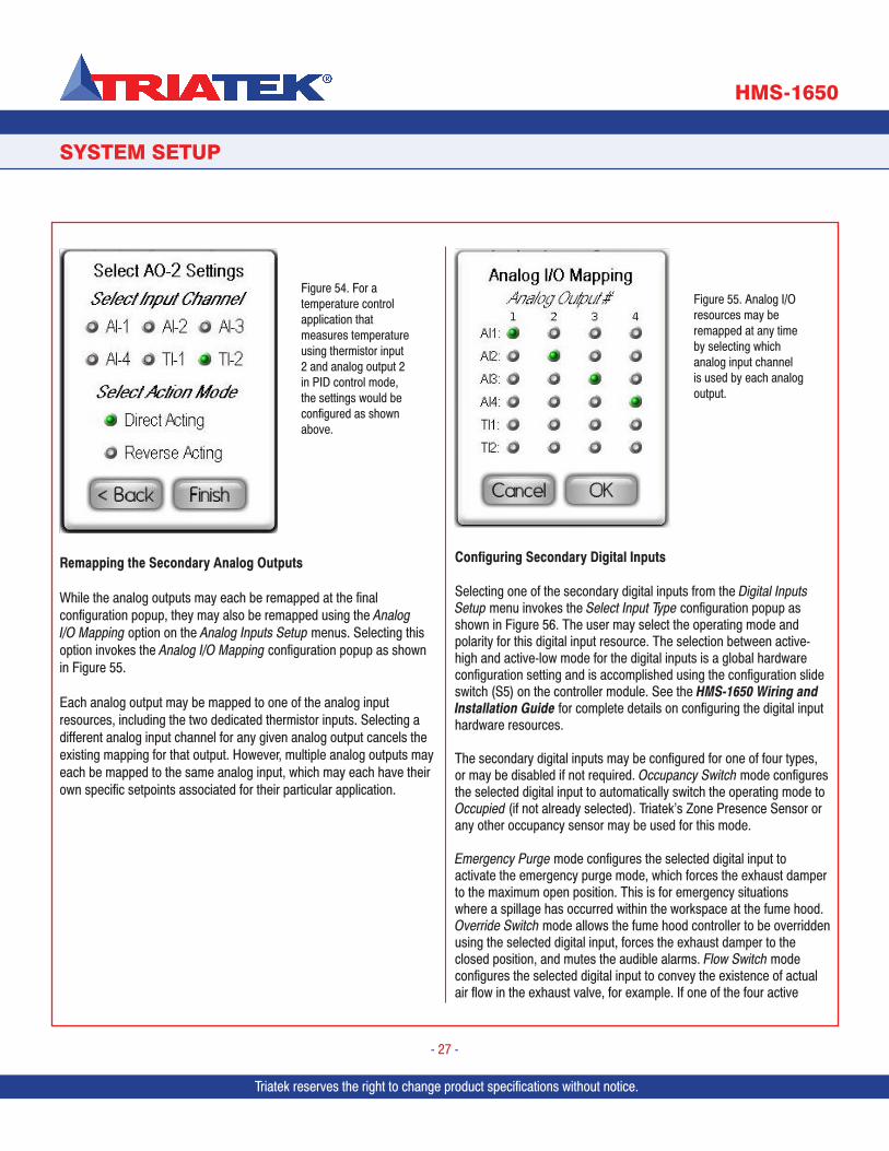
Clicking the Next button invokes the final Select AO-x Settings configuration popup where the user may remap the analog output to one of the other analog inputs and change the action mode for the control output.
For example, if analog output 2 is being used in a temperature control application which receives the temperature signal via thermistor input 2, TI-2 should be selected in the Select Input Channel section of the configuration popup as shown in Figure 54.
Figure 51. The HMS-1650 supports the use of NTC Type 2 and 3 thermistors for temperature control and/or monitoring applications.
Figure 52. A temperature setpoint may be entered here for temperature control applications using one of the PID analog outputs.
Figure 53. Each of the three secondary analog outputs may be independently configured for direct or PID analog output mode, depending on the application requirements.
Triatek reserves the right to change product specifications without notice.
SYSTEM SETUP
HMS-1650
Triatek reserves the right to change product specifications without notice.
- 27 -
Remapping the Secondary Analog Outputs
While the analog outputs may each be remapped at the final configuration popup, they may also be remapped using the Analog I/O Mapping option on the Analog Inputs Setup menus. Selecting this option invokes the Analog I/O Mapping configuration popup as shown in Figure 55.
Each analog output may be mapped to one of the analog input resources, including the two dedicated thermistor inputs. Selecting a different analog input channel for any given analog output cancels the existing mapping for that output. However, multiple analog outputs may each be mapped to the same analog input, which may each have their own specific setpoints associated for their particular application.
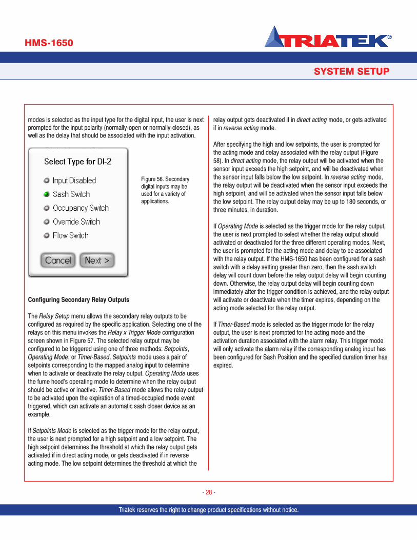
Configuring Secondary Digital Inputs
Selecting one of the secondary digital inputs from the Digital Inputs Setup menu invokes the Select Input Type configuration popup as shown in Figure 56. The user may select the operating mode and polarity for this digital input resource. The selection between active-high and active-low mode for the digital inputs is a global hardware configuration setting and is accomplished using the configuration slide switch (S5) on the controller module. See the HMS-1650 Wiring and Installation Guide for complete details on configuring the digital input hardware resources.
The secondary digital inputs may be configured for one of four types, or may be disabled if not required. Occupancy Switch mode configures the selected digital input to automatically switch the operating mode to Occupied (if not already selected). Triatek’s Zone Presence Sensor or any other occupancy sensor may be used for this mode.
Emergency Purge mode configures the selected digital input to activate the emergency purge mode, which forces the exhaust damper to the maximum open position. This is for emergency situations where a spillage has occurred within the workspace at the fume hood. Override Switch mode allows the fume hood controller to be overridden using the selected digital input, forces the exhaust damper to the closed position, and mutes the audible alarms. Flow Switch mode configures the selected digital input to convey the existence of actual air flow in the exhaust valve, for example. If one of the four active
Figure 54. For a temperature control application that measures temperature using thermistor input 2 and analog output 2 in PID control mode, the settings would be configured as shown above.
Figure 55. Analog I/O resources may be remapped at any time by selecting which analog input channel is used by each analog output.
Triatek reserves the right to change product specifications without notice. Triatek reserves the right to change product specifications without notice.
SYSTEM SETUP
HMS-1650
Triatek reserves the right to change product specifications without notice.
- 28 -
modes is selected as the input type for the digital input, the user is next prompted for the input polarity (normally-open or normally-closed), as well as the delay that should be associated with the input activation.
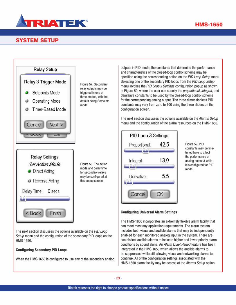
Configuring Secondary Relay Outputs
The Relay Setup menu allows the secondary relay outputs to be configured as required by the specific application. Selecting one of the relays on this menu invokes the Relay x Trigger Mode configuration screen shown in Figure 57. The selected relay output may be configured to be triggered using one of three methods: Setpoints, Operating Mode, or Timer-Based. Setpoints mode uses a pair of setpoints corresponding to the mapped analog input to determine when to activate or deactivate the relay output. Operating Mode uses the fume hood’s operating mode to determine when the relay output should be active or inactive. Timer-Based mode allows the relay output to be activated upon the expiration of a timed-occupied mode event triggered, which can activate an automatic sash closer device as an example.
If Setpoints Mode is selected as the trigger mode for the relay output, the user is next prompted for a high setpoint and a low setpoint. The high setpoint determines the threshold at which the relay output gets activated if in direct acting mode, or gets deactivated if in reverse acting mode. The low setpoint determines the threshold at which the
relay output gets deactivated if in direct acting mode, or gets activated if in reverse acting mode.
After specifying the high and low setpoints, the user is prompted for the acting mode and delay associated with the relay output (Figure 58). In direct acting mode, the relay output will be activated when the sensor input exceeds the high setpoint, and will be deactivated when the sensor input falls below the low setpoint. In reverse acting mode, the relay output will be deactivated when the sensor input exceeds the high setpoint, and will be activated when the sensor input falls below the low setpoint. The relay output delay may be up to 180 seconds, or three minutes, in duration.
If Operating Mode is selected as the trigger mode for the relay output, the user is next prompted to select whether the relay output should activated or deactivated for the three different operating modes. Next, the user is prompted for the acting mode and delay to be associated with the relay output. If the HMS-1650 has been configured for a sash switch with a delay setting greater than zero, then the sash switch delay will count down before the relay output delay will begin counting down. Otherwise, the relay output delay will begin counting down immediately after the trigger condition is achieved, and the relay output will activate or deactivate when the timer expires, depending on the acting mode selected for the relay output.
If Timer-Based mode is selected as the trigger mode for the relay output, the user is next prompted for the acting mode and the activation duration associated with the alarm relay. This trigger mode will only activate the alarm relay if the corresponding analog input has been configured for Sash Position and the specified duration timer has expired.
Figure 56. Secondary digital inputs may be used for a variety of applications.
Triatek reserves the right to change product specifications without notice.
SYSTEM SETUP
HMS-1650
Triatek reserves the right to change product specifications without notice.
- 29 -
The next section discusses the options available on the PID Loop Setup menu and the configuration of the secondary PID loops on the HMS-1650.
Configuring Secondary PID Loops
When the HMS-1650 is configured to use any of the secondary analog
outputs in PID mode, the constants that determine the performance and characteristics of the closed-loop control scheme may be specified using the corresponding option on the PID Loop Setup menu. Selecting one of the secondary PID loops from the PID Loop Setup menu invokes the PID Loop x Settings configuration popup as shown in Figure 59, where the user can specify the proportional, integral, and derivative constants to be used by the closed-loop control scheme for the corresponding analog output. The three dimensionless PID constants may vary from zero to 100 using the three sliders on the configuration screen.
The next section discusses the options available on the Alarms Setup menu and the configuration of the alarm resources on the HMS-1650.
Configuring Universal Alarm Settings
The HMS-1650 incorporates an extremely flexible alarm facility that can meet most any application requirements. The alarm system includes both visual and audible alarms that may be independently enabled for each monitored analog input in the system. There are two distinct audible alarms to indicate higher and lower priority alarm conditions by sound alone. An Alarm Quiet Period feature has been integrated in the HMS-1650 which allows the audible alarms to be suppressed while still allowing visual and networking alarms to continue. All of the configuration settings associated with the HMS-1650 alarm facility may be access at the Alarms Setup option
Figure 57. Secondary relay outputs may be triggered in one of three modes, with the default being Setpoints mode.
Figure 58. The action mode and delay time for secondary relays may be configured at this popup screen.
Figure 59. PID constants may be fine-tuned here to affect the performance of analog output 3 while it is configured for PID mode.
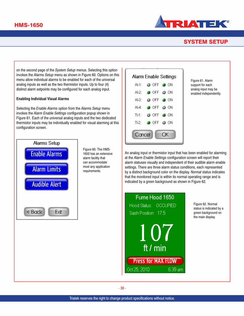
Triatek reserves the right to change product specifications without notice. Triatek reserves the right to change product specifications without notice.
SYSTEM SETUP
HMS-1650
Triatek reserves the right to change product specifications without notice.
- 30 -
on the second page of the System Setup menus. Selecting this option invokes the Alarms Setup menu as shown in Figure 60. Options on this menu allow individual alarms to be enabled for each of the universal analog inputs as well as the two thermistor inputs. Up to four (4) distinct alarm setpoints may be configured for each analog input.
Enabling Individual Visual Alarms
Selecting the Enable Alarms option from the Alarms Setup menu invokes the Alarm Enable Settings configuration popup shown in Figure 61. Each of the universal analog inputs and the two dedicated thermistor inputs may be individually enabled for visual alarming at this configuration screen.
An analog input or thermistor input that has been enabled for alarming at the Alarm Enable Settings configuration screen will report their alarm statuses visually and independent of their audible alarm enable settings. There are three alarm status conditions, each represented by a distinct background color on the display. Normal status indicates that the monitored input is within its normal operating range and is indicated by a green background as shown in Figure 62.
Figure 60. The HMS-1650 has an extensive alarm facility that can accommodate most any application requirements.
Figure 61. Alarm support for each analog input may be enabled independently.
Figure 62. Normal status is indicated by a green background on the main display.
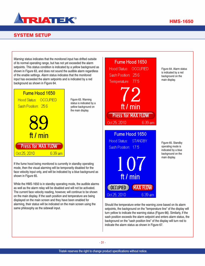
Triatek reserves the right to change product specifications without notice.
SYSTEM SETUP
HMS-1650
Triatek reserves the right to change product specifications without notice.
- 31 -
Warning status indicates that the monitored input has drifted outside of its normal operating range, but has not yet exceeded the alarm setpoints. This status condition is indicated by a yellow background as shown in Figure 63, and does not sound the audible alarm regardless of the enable settings. Alarm status indicates that the monitored input has exceeded the alarm setpoints and is indicated by a red background as shown in Figure 64.
If the fume hood being monitored is currently in standby operating mode, then the visual alarming will be temporarily disabled for the face velocity input only, and will be indicated by a blue background as shown in Figure 65.
While the HMS-1650 is in standby operating mode, the audible alarms as well as the alarm relay will be disabled and will not be activated. The current face velocity reading, however, will continue to be shown on the main display. If the sash position and temperature are being displayed on the main screen and they have been enabled for alarming, their status will be indicated on the main screen using the same philosophy as the sidewall input.
Should the temperature enter the warning zone based on its alarm setpoints, the background on the “temperature line” of the display will turn yellow to indicate the warning status (Figure 66). Similarly, if the sash position exceeds the alarm setpoint and enters alarm status, the background on the “sash position line” of the display will turn red to indicate the alarm status as shown in Figure 67.
Figure 63. Warning status is indicated by a yellow background on the main display.
Figure 64. Alarm status is indicated by a red background on the main display.
Figure 65. Standby operating mode is indicated by a blue background on the main display.
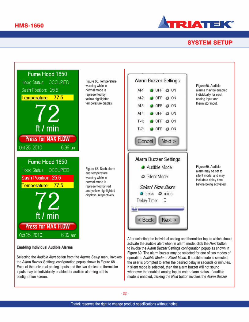
Triatek reserves the right to change product specifications without notice. Triatek reserves the right to change product specifications without notice.
SYSTEM SETUP
HMS-1650
Triatek reserves the right to change product specifications without notice.
- 32 -
Enabling Individual Audible Alarms
Selecting the Audible Alert option from the Alarms Setup menu invokes the Alarm Buzzer Settings configuration popup shown in Figure 68. Each of the universal analog inputs and the two dedicated thermistor inputs may be individually enabled for audible alarming at this configuration screen.
After selecting the individual analog and thermistor inputs which should activate the audible alert when in alarm mode, click the Next button to invoke the Alarm Buzzer Settings configuration popup as shown in Figure 69. The alarm buzzer may be selected for one of two modes of operation: Audible Mode or Silent Mode. If audible mode is selected, the user is prompted to enter the desired delay in seconds or minutes. If silent mode is selected, then the alarm buzzer will not sound whenever the enabled analog inputs enter alarm status. If audible mode is enabled, clicking the Next button invokes the Alarm Buzzer
Figure 66. Temperature warning while in normal mode is represented by yellow highlighted temperature display.
Figure 67. Sash alarm and temperature warning while in normal mode is represented by red and yellow highlighted displays, respectively.
Figure 68. Audible alarms may be enabled individually for each analog input and thermistor input.
Figure 69. Audible alarm may be set to silent mode, and may include a delay time before being activated.
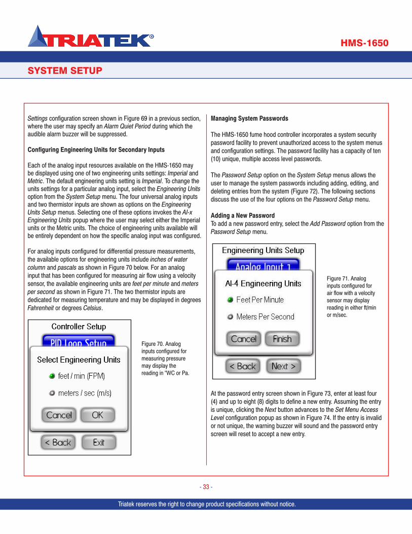
Triatek reserves the right to change product specifications without notice.
SYSTEM SETUP
HMS-1650
Triatek reserves the right to change product specifications without notice.
- 33 -
Settings configuration screen shown in Figure 69 in a previous section, where the user may specify an Alarm Quiet Period during which the audible alarm buzzer will be suppressed.
Configuring Engineering Units for Secondary Inputs
Each of the analog input resources available on the HMS-1650 may be displayed using one of two engineering units settings: Imperial and Metric. The default engineering units setting is Imperial. To change the units settings for a particular analog input, select the Engineering Units option from the System Setup menu. The four universal analog inputs and two thermistor inputs are shown as options on the Engineering Units Setup menus. Selecting one of these options invokes the AI-x Engineering Units popup where the user may select either the Imperial units or the Metric units. The choice of engineering units available will be entirely dependent on how the specific analog input was configured.
For analog inputs configured for differential pressure measurements, the available options for engineering units include inches of water column and pascals as shown in Figure 70 below. For an analog input that has been configured for measuring air flow using a velocity sensor, the available engineering units are feet per minute and meters per second as shown in Figure 71. The two thermistor inputs are dedicated for measuring temperature and may be displayed in degrees Fahrenheit or degrees Celsius.
Managing System Passwords
The HMS-1650 fume hood controller incorporates a system security password facility to prevent unauthorized access to the system menus and configuration settings. The password facility has a capacity of ten (10) unique, multiple access level passwords.
The Password Setup option on the System Setup menus allows the user to manage the system passwords including adding, editing, and deleting entries from the system (Figure 72). The following sections discuss the use of the four options on the Password Setup menu.
Adding a New Password To add a new password entry, select the Add Password option from the Password Setup menu.
At the password entry screen shown in Figure 73, enter at least four (4) and up to eight (8) digits to define a new entry. Assuming the entry is unique, clicking the Next button advances to the Set Menu Access Level configuration popup as shown in Figure 74. If the entry is invalid or not unique, the warning buzzer will sound and the password entry screen will reset to accept a new entry.
Figure 70. Analog inputs configured for measuring pressure may display the reading in “WC or Pa.
Figure 71. Analog inputs configured for air flow with a velocity sensor may display reading in either ft/min or m/sec.
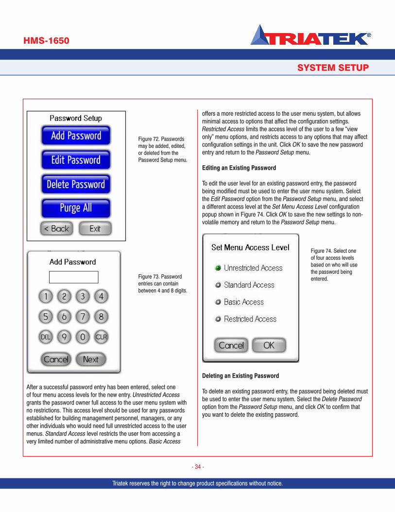
Triatek reserves the right to change product specifications without notice. Triatek reserves the right to change product specifications without notice.
SYSTEM SETUP
HMS-1650
Triatek reserves the right to change product specifications without notice.
- 34 -
After a successful password entry has been entered, select one of four menu access levels for the new entry. Unrestricted Access grants the password owner full access to the user menu system with no restrictions. This access level should be used for any passwords established for building management personnel, managers, or any other individuals who would need full unrestricted access to the user menus. Standard Access level restricts the user from accessing a very limited number of administrative menu options. Basic Access
offers a more restricted access to the user menu system, but allows minimal access to options that affect the configuration settings. Restricted Access limits the access level of the user to a few “view only” menu options, and restricts access to any options that may affect configuration settings in the unit. Click OK to save the new password entry and return to the Password Setup menu.
Editing an Existing Password
To edit the user level for an existing password entry, the password being modified must be used to enter the user menu system. Select the Edit Password option from the Password Setup menu, and select a different access level at the Set Menu Access Level configuration popup shown in Figure 74. Click OK to save the new settings to non-volatile memory and return to the Password Setup menu.
Deleting an Existing Password
To delete an existing password entry, the password being deleted must be used to enter the user menu system. Select the Delete Password option from the Password Setup menu, and click OK to confirm that you want to delete the existing password.
Figure 72. Passwords may be added, edited, or deleted from the Password Setup menu.
Figure 73. Password entries can contain between 4 and 8 digits.
Figure 74. Select one of four access levels based on who will use the password being entered.
Triatek reserves the right to change product specifications without notice.
SYSTEM SETUP
HMS-1650
Triatek reserves the right to change product specifications without notice.
- 35 -
Purging All PasswordsTo purge all existing password entries from the system, an unrestricted password must be used to enter the user menu system. Select the Purge All Passwords option from the Password Setup menu, and click OK to confirm that you want to purge all existing passwords from the system.
The next section discusses the options available on the Display Setup menu and the management of the display options for the HMS-1650.
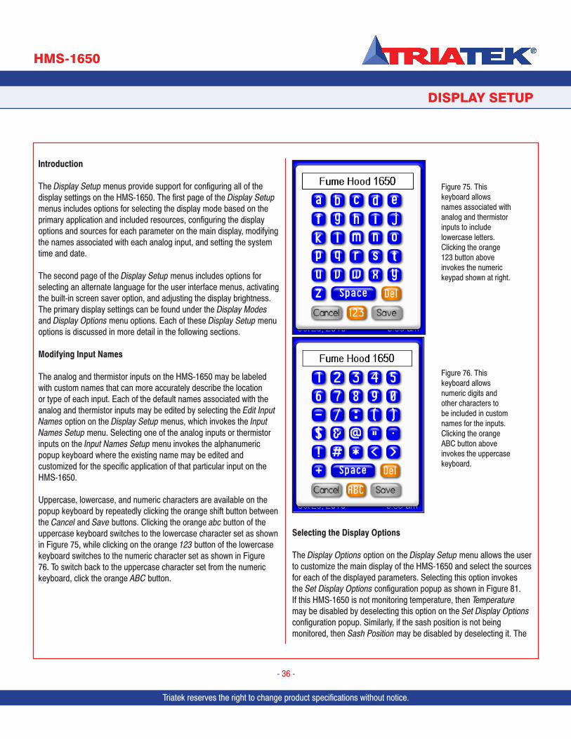
Triatek reserves the right to change product specifications without notice.
Introduction
The Display Setup menus provide support for configuring all of the display settings on the HMS-1650. The first page of the Display Setup menus includes options for selecting the display mode based on the primary application and included resources, configuring the display options and sources for each parameter on the main display, modifying the names associated with each analog input, and setting the system time and date.
The second page of the Display Setup menus includes options for selecting an alternate language for the user interface menus, activating the built-in screen saver option, and adjusting the display brightness. The primary display settings can be found under the Display Modes and Display Options menu options. Each of these Display Setup menu options is discussed in more detail in the following sections.
Modifying Input Names
The analog and thermistor inputs on the HMS-1650 may be labeled with custom names that can more accurately describe the location or type of each input. Each of the default names associated with the analog and thermistor inputs may be edited by selecting the Edit Input Names option on the Display Setup menus, which invokes the Input Names Setup menu. Selecting one of the analog inputs or thermistor inputs on the Input Names Setup menu invokes the alphanumeric popup keyboard where the existing name may be edited and customized for the specific application of that particular input on the HMS-1650.
Uppercase, lowercase, and numeric characters are available on the popup keyboard by repeatedly clicking the orange shift button between the Cancel and Save buttons. Clicking the orange abc button of the uppercase keyboard switches to the lowercase character set as shown in Figure 75, while clicking on the orange 123 button of the lowercase keyboard switches to the numeric character set as shown in Figure 76. To switch back to the uppercase character set from the numeric keyboard, click the orange ABC button.
Selecting the Display Options
The Display Options option on the Display Setup menu allows the user to customize the main display of the HMS-1650 and select the sources for each of the displayed parameters. Selecting this option invokes the Set Display Options configuration popup as shown in Figure 81. If this HMS-1650 is not monitoring temperature, then Temperature may be disabled by deselecting this option on the Set Display Options configuration popup. Similarly, if the sash position is not being monitored, then Sash Position may be disabled by deselecting it. The
Triatek reserves the right to change product specifications without notice.
DISPLAY SETUP
HMS-1650
Triatek reserves the right to change product specifications without notice.
- 36 -
Figure 75. This keyboard allows names associated with analog and thermistor inputs to include lowercase letters. Clicking the orange 123 button above invokes the numeric keypad shown at right.
Figure 76. This keyboard allows numeric digits and other characters to be included in custom names for the inputs. Clicking the orange ABC button above invokes the uppercase keyboard.
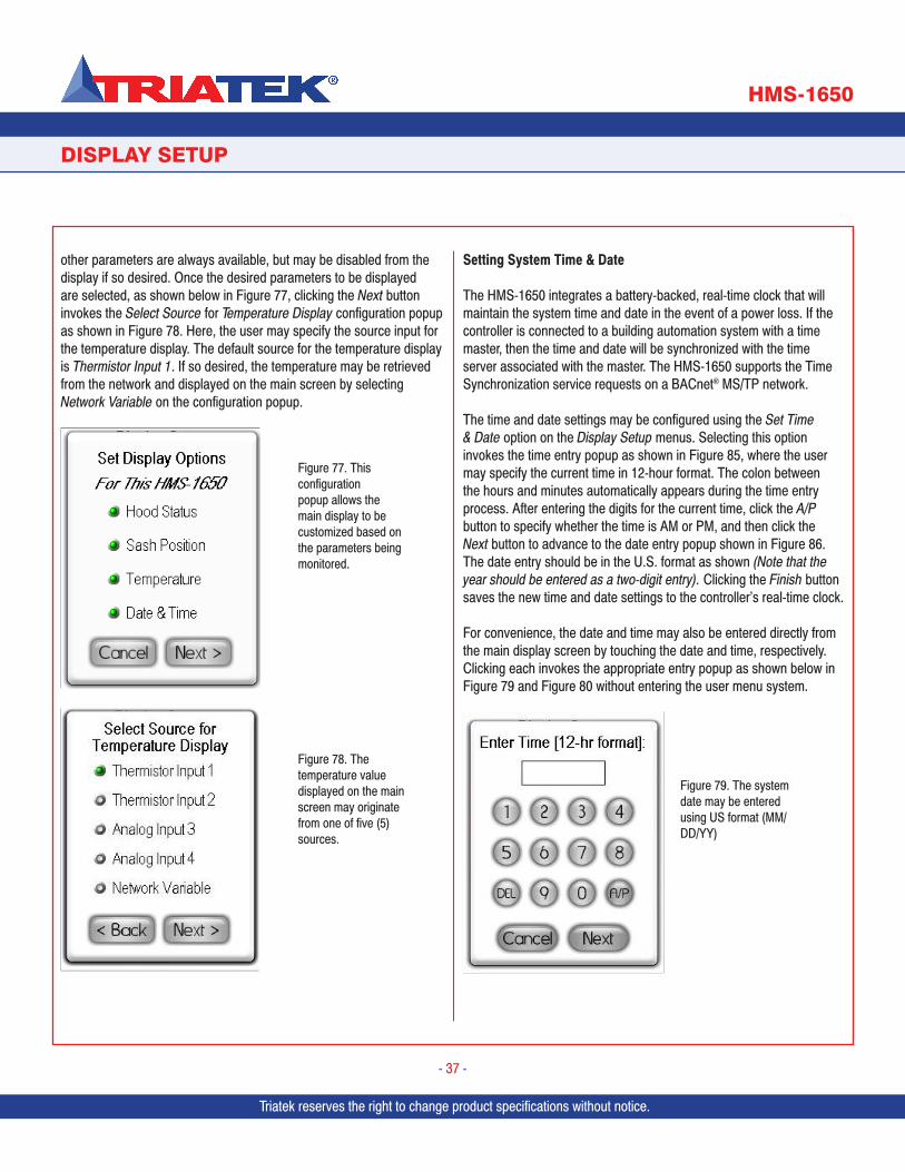
Triatek reserves the right to change product specifications without notice.
DISPLAY SETUP
HMS-1650
Triatek reserves the right to change product specifications without notice.
- 37 -
other parameters are always available, but may be disabled from the display if so desired. Once the desired parameters to be displayed are selected, as shown below in Figure 77, clicking the Next button invokes the Select Source for Temperature Display configuration popup as shown in Figure 78. Here, the user may specify the source input for the temperature display. The default source for the temperature display is Thermistor Input 1. If so desired, the temperature may be retrieved from the network and displayed on the main screen by selecting Network Variable on the configuration popup.
Setting System Time & Date
The HMS-1650 integrates a battery-backed, real-time clock that will maintain the system time and date in the event of a power loss. If the controller is connected to a building automation system with a time master, then the time and date will be synchronized with the time server associated with the master. The HMS-1650 supports the Time Synchronization service requests on a BACnet® MS/TP network.
The time and date settings may be configured using the Set Time & Date option on the Display Setup menus. Selecting this option invokes the time entry popup as shown in Figure 85, where the user may specify the current time in 12-hour format. The colon between the hours and minutes automatically appears during the time entry process. After entering the digits for the current time, click the A/P button to specify whether the time is AM or PM, and then click the Next button to advance to the date entry popup shown in Figure 86. The date entry should be in the U.S. format as shown (Note that the year should be entered as a two-digit entry). Clicking the Finish button saves the new time and date settings to the controller’s real-time clock.
For convenience, the date and time may also be entered directly from the main display screen by touching the date and time, respectively. Clicking each invokes the appropriate entry popup as shown below in Figure 79 and Figure 80 without entering the user menu system.
Figure 79. The system date may be entered using US format (MM/DD/YY)
Figure 77. This configuration popup allows the main display to be customized based on the parameters being monitored.
Figure 78. The temperature value displayed on the main screen may originate from one of five (5) sources.
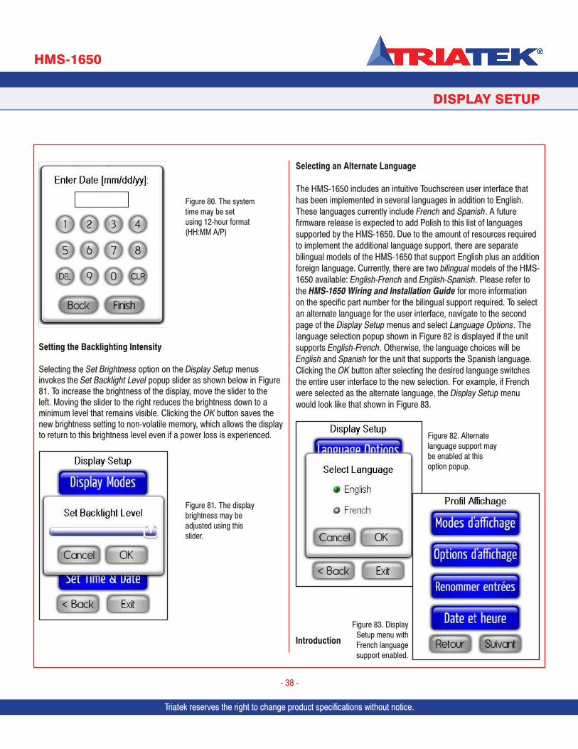
Triatek reserves the right to change product specifications without notice. Triatek reserves the right to change product specifications without notice.
DISPLAY SETUP
HMS-1650
Triatek reserves the right to change product specifications without notice.
- 38 -
Setting the Backlighting Intensity
Selecting the Set Brightness option on the Display Setup menus invokes the Set Backlight Level popup slider as shown below in Figure 81. To increase the brightness of the display, move the slider to the left. Moving the slider to the right reduces the brightness down to a minimum level that remains visible. Clicking the OK button saves the new brightness setting to non-volatile memory, which allows the display to return to this brightness level even if a power loss is experienced.
Selecting an Alternate Language
The HMS-1650 includes an intuitive Touchscreen user interface that has been implemented in several languages in addition to English. These languages currently include French and Spanish. A future firmware release is expected to add Polish to this list of languages supported by the HMS-1650. Due to the amount of resources required to implement the additional language support, there are separate bilingual models of the HMS-1650 that support English plus an addition foreign language. Currently, there are two bilingual models of the HMS-1650 available: English-French and English-Spanish. Please refer to the HMS-1650 Wiring and Installation Guide for more information on the specific part number for the bilingual support required. To select an alternate language for the user interface, navigate to the second page of the Display Setup menus and select Language Options. The language selection popup shown in Figure 82 is displayed if the unit supports English-French. Otherwise, the language choices will be English and Spanish for the unit that supports the Spanish language. Clicking the OK button after selecting the desired language switches the entire user interface to the new selection. For example, if French were selected as the alternate language, the Display Setup menu would look like that shown in Figure 83.
Introduction
Figure 80. The system time may be set using 12-hour format (HH:MM A/P)
Figure 82. Alternate language support may be enabled at this option popup.
Figure 83. Display Setup menu with French language support enabled.
Figure 81. The display brightness may be adjusted using this slider.
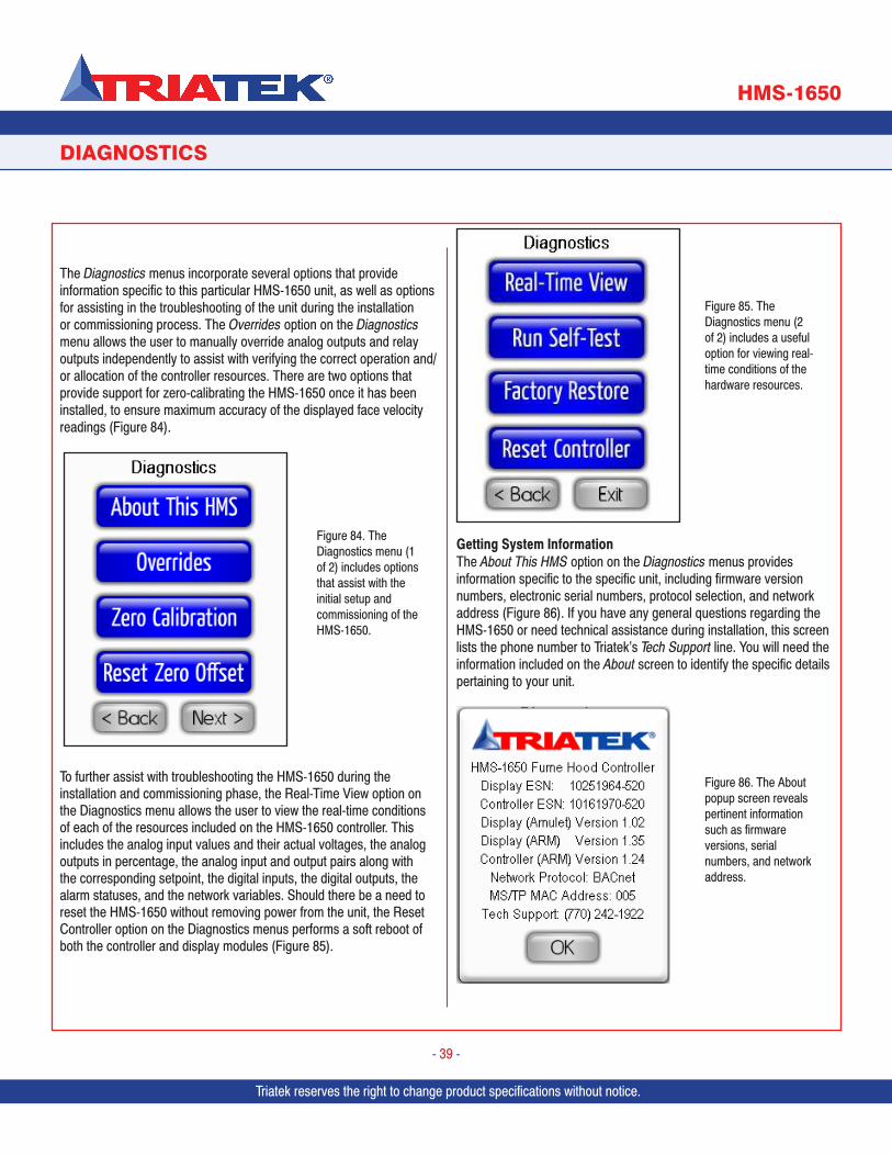
Triatek reserves the right to change product specifications without notice.
DIAGNOSTICS
HMS-1650
Triatek reserves the right to change product specifications without notice.
- 39 -
The Diagnostics menus incorporate several options that provide information specific to this particular HMS-1650 unit, as well as options for assisting in the troubleshooting of the unit during the installation or commissioning process. The Overrides option on the Diagnostics menu allows the user to manually override analog outputs and relay outputs independently to assist with verifying the correct operation and/or allocation of the controller resources. There are two options that provide support for zero-calibrating the HMS-1650 once it has been installed, to ensure maximum accuracy of the displayed face velocity readings (Figure 84).
To further assist with troubleshooting the HMS-1650 during the installation and commissioning phase, the Real-Time View option on the Diagnostics menu allows the user to view the real-time conditions of each of the resources included on the HMS-1650 controller. This includes the analog input values and their actual voltages, the analog outputs in percentage, the analog input and output pairs along with the corresponding setpoint, the digital inputs, the digital outputs, the alarm statuses, and the network variables. Should there be a need to reset the HMS-1650 without removing power from the unit, the Reset Controller option on the Diagnostics menus performs a soft reboot of both the controller and display modules (Figure 85).
Getting System InformationThe About This HMS option on the Diagnostics menus provides information specific to the specific unit, including firmware version numbers, electronic serial numbers, protocol selection, and network address (Figure 86). If you have any general questions regarding the HMS-1650 or need technical assistance during installation, this screen lists the phone number to Triatek’s Tech Support line. You will need the information included on the About screen to identify the specific details pertaining to your unit.
Figure 84. The Diagnostics menu (1 of 2) includes options that assist with the initial setup and commissioning of the HMS-1650.
Figure 85. The Diagnostics menu (2 of 2) includes a useful option for viewing real-time conditions of the hardware resources.
Figure 86. The About popup screen reveals pertinent information such as firmware versions, serial numbers, and network address.
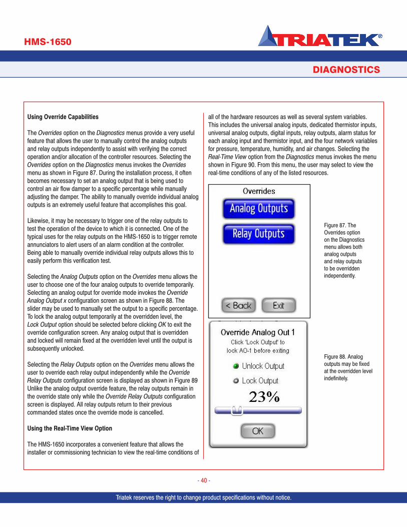
Triatek reserves the right to change product specifications without notice. Triatek reserves the right to change product specifications without notice.
DIAGNOSTICS
HMS-1650
Triatek reserves the right to change product specifications without notice.
- 40 -
Using Override Capabilities
The Overrides option on the Diagnostics menus provide a very useful feature that allows the user to manually control the analog outputs and relay outputs independently to assist with verifying the correct operation and/or allocation of the controller resources. Selecting the Overrides option on the Diagnostics menus invokes the Overrides menu as shown in Figure 87. During the installation process, it often becomes necessary to set an analog output that is being used to control an air flow damper to a specific percentage while manually adjusting the damper. The ability to manually override individual analog outputs is an extremely useful feature that accomplishes this goal.
Likewise, it may be necessary to trigger one of the relay outputs to test the operation of the device to which it is connected. One of the typical uses for the relay outputs on the HMS-1650 is to trigger remote annunciators to alert users of an alarm condition at the controller. Being able to manually override individual relay outputs allows this to easily perform this verification test.
Selecting the Analog Outputs option on the Overrides menu allows the user to choose one of the four analog outputs to override temporarily. Selecting an analog output for override mode invokes the Override Analog Output x configuration screen as shown in Figure 88. The slider may be used to manually set the output to a specific percentage. To lock the analog output temporarily at the overridden level, the Lock Output option should be selected before clicking OK to exit the override configuration screen. Any analog output that is overridden and locked will remain fixed at the overridden level until the output is subsequently unlocked.
Selecting the Relay Outputs option on the Overrides menu allows the user to override each relay output independently while the Override Relay Outputs configuration screen is displayed as shown in Figure 89 Unlike the analog output override feature, the relay outputs remain in the override state only while the Override Relay Outputs configuration screen is displayed. All relay outputs return to their previous commanded states once the override mode is cancelled.
Using the Real-Time View Option
The HMS-1650 incorporates a convenient feature that allows the installer or commissioning technician to view the real-time conditions of
all of the hardware resources as well as several system variables.This includes the universal analog inputs, dedicated thermistor inputs, universal analog outputs, digital inputs, relay outputs, alarm status for each analog input and thermistor input, and the four network variables for pressure, temperature, humidity, and air changes. Selecting the Real-Time View option from the Diagnostics menus invokes the menu shown in Figure 90. From this menu, the user may select to view the real-time conditions of any of the listed resources.
Figure 87. The Overrides option on the Diagnostics menu allows both analog outputs and relay outputs to be overridden independently.
Figure 88. Analog outputs may be fixed at the overridden level indefinitely.
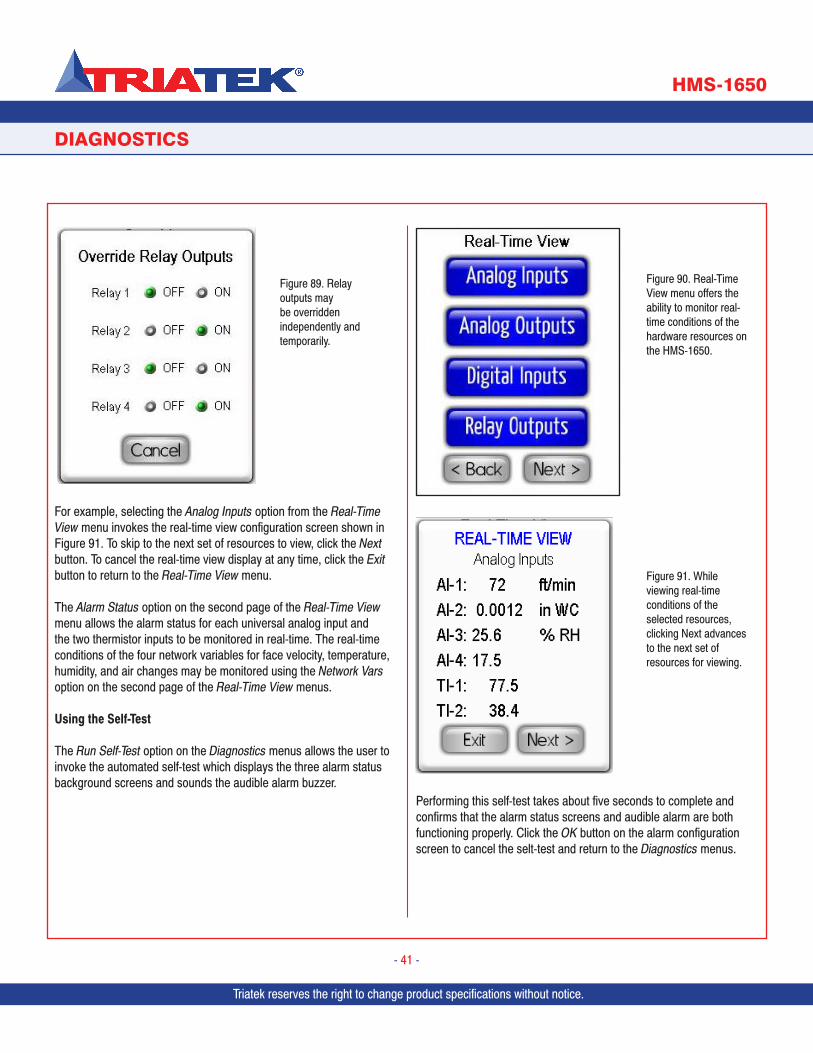
Triatek reserves the right to change product specifications without notice.
DIAGNOSTICS
HMS-1650
Triatek reserves the right to change product specifications without notice.
- 41 -
For example, selecting the Analog Inputs option from the Real-Time View menu invokes the real-time view configuration screen shown in Figure 91. To skip to the next set of resources to view, click the Next button. To cancel the real-time view display at any time, click the Exit button to return to the Real-Time View menu.
The Alarm Status option on the second page of the Real-Time View menu allows the alarm status for each universal analog input and the two thermistor inputs to be monitored in real-time. The real-time conditions of the four network variables for face velocity, temperature, humidity, and air changes may be monitored using the Network Vars option on the second page of the Real-Time View menus.
Using the Self-Test
The Run Self-Test option on the Diagnostics menus allows the user to invoke the automated self-test which displays the three alarm status background screens and sounds the audible alarm buzzer.
Performing this self-test takes about five seconds to complete and confirms that the alarm status screens and audible alarm are both functioning properly. Click the OK button on the alarm configuration screen to cancel the selt-test and return to the Diagnostics menus.
Figure 90. Real-Time View menu offers the ability to monitor real-time conditions of the hardware resources on the HMS-1650.
Figure 91. While viewing real-time conditions of the selected resources, clicking Next advances to the next set of resources for viewing.
Figure 89. Relay outputs may be overridden independently and temporarily.
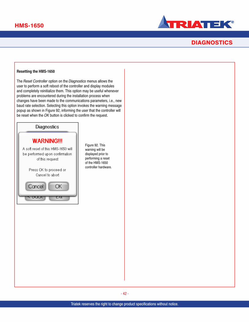
Triatek reserves the right to change product specifications without notice. Triatek reserves the right to change product specifications without notice.
DIAGNOSTICS
HMS-1650
Triatek reserves the right to change product specifications without notice.
- 42 -
Resetting the HMS-1650
The Reset Controller option on the Diagnostics menus allows the user to perform a soft reboot of the controller and display modules and completely reinitialize them. This option may be useful whenever problems are encountered during the installation process when changes have been made to the communications parameters, i.e., new baud rate selection. Selecting this option invokes the warning message popup as shown in Figure 92, informing the user that the controller will be reset when the OK button is clicked to confirm the request.
Figure 92. This warning will be displayed prior to performing a reset of the HMS-1650 controller hardware.
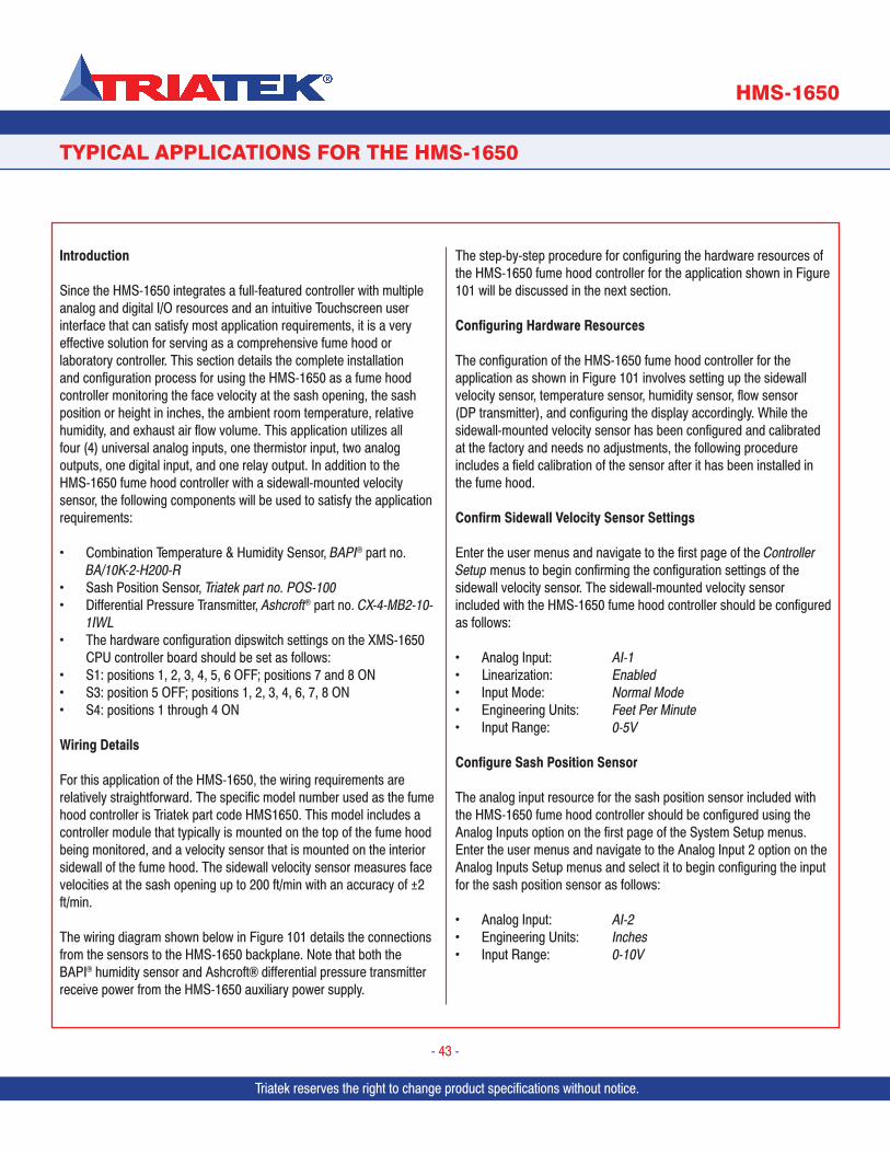
Triatek reserves the right to change product specifications without notice.
TYPICAL APPLICATIONS FOR THE HMS-1650
HMS-1650
Triatek reserves the right to change product specifications without notice.
- 43 -
Introduction
Since the HMS-1650 integrates a full-featured controller with multiple analog and digital I/O resources and an intuitive Touchscreen user interface that can satisfy most application requirements, it is a very effective solution for serving as a comprehensive fume hood or laboratory controller. This section details the complete installation and configuration process for using the HMS-1650 as a fume hood controller monitoring the face velocity at the sash opening, the sash position or height in inches, the ambient room temperature, relative humidity, and exhaust air flow volume. This application utilizes all four (4) universal analog inputs, one thermistor input, two analog outputs, one digital input, and one relay output. In addition to the HMS-1650 fume hood controller with a sidewall-mounted velocity sensor, the following components will be used to satisfy the application requirements:
• Combination Temperature & Humidity Sensor, BAPI® part no. BA/10K-2-H200-R
• Sash Position Sensor, Triatek part no. POS-100• Differential Pressure Transmitter, Ashcroft® part no. CX-4-MB2-10-
1IWL• The hardware configuration dipswitch settings on the XMS-1650
CPU controller board should be set as follows:• S1: positions 1, 2, 3, 4, 5, 6 OFF; positions 7 and 8 ON• S3: position 5 OFF; positions 1, 2, 3, 4, 6, 7, 8 ON• S4: positions 1 through 4 ON Wiring Details
For this application of the HMS-1650, the wiring requirements are relatively straightforward. The specific model number used as the fume hood controller is Triatek part code HMS1650. This model includes a controller module that typically is mounted on the top of the fume hood being monitored, and a velocity sensor that is mounted on the interior sidewall of the fume hood. The sidewall velocity sensor measures face velocities at the sash opening up to 200 ft/min with an accuracy of ±2 ft/min.
The wiring diagram shown below in Figure 101 details the connections from the sensors to the HMS-1650 backplane. Note that both the BAPI® humidity sensor and Ashcroft® differential pressure transmitter receive power from the HMS-1650 auxiliary power supply.
The step-by-step procedure for configuring the hardware resources of the HMS-1650 fume hood controller for the application shown in Figure 101 will be discussed in the next section.
Configuring Hardware Resources
The configuration of the HMS-1650 fume hood controller for the application as shown in Figure 101 involves setting up the sidewall velocity sensor, temperature sensor, humidity sensor, flow sensor (DP transmitter), and configuring the display accordingly. While the sidewall-mounted velocity sensor has been configured and calibrated at the factory and needs no adjustments, the following procedure includes a field calibration of the sensor after it has been installed in the fume hood.
Confirm Sidewall Velocity Sensor Settings
Enter the user menus and navigate to the first page of the Controller Setup menus to begin confirming the configuration settings of the sidewall velocity sensor. The sidewall-mounted velocity sensor included with the HMS-1650 fume hood controller should be configured as follows:
• Analog Input: AI-1• Linearization: Enabled• Input Mode: Normal Mode• Engineering Units: Feet Per Minute• Input Range: 0-5V
Configure Sash Position Sensor
The analog input resource for the sash position sensor included with the HMS-1650 fume hood controller should be configured using the Analog Inputs option on the first page of the System Setup menus. Enter the user menus and navigate to the Analog Input 2 option on the Analog Inputs Setup menus and select it to begin configuring the input for the sash position sensor as follows:
• Analog Input: AI-2• Engineering Units: Inches• Input Range: 0-10V
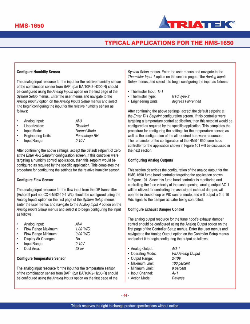
Triatek reserves the right to change product specifications without notice. Triatek reserves the right to change product specifications without notice.
TYPICAL APPLICATIONS FOR THE HMS-1650
HMS-1650
Triatek reserves the right to change product specifications without notice.
- 44 -
Configure Humidity Sensor
The analog input resource for the input for the relative humidity sensor of the combination sensor from BAPI (p/n BA/10K-2-H200-R) should be configured using the Analog Inputs option on the first page of the System Setup menus. Enter the user menus and navigate to the Analog Input 3 option on the Analog Inputs Setup menus and select it to begin configuring the input for the relative humidity sensor as follows:
• Analog Input: AI-3• Linearization: Disabled• Input Mode: Normal Mode• Engineering Units: Percentage RH• Input Range: 0-10V
After confirming the above settings, accept the default setpoint of zero at the Enter AI-3 Setpoint configuration screen. If this controller were targeting a humidity control application, then this setpoint would be configured as required by the specific application. This completes the procedure for configuring the settings for the relative humidity sensor.
Configure Flow Sensor
The analog input resource for the flow input from the DP transmitter (Ashcroft part no. CX-4-MB2-10-1IWL) should be configured using the Analog Inputs option on the first page of the System Setup menus. Enter the user menus and navigate to the Analog Input 4 option on the Analog Inputs Setup menus and select it to begin configuring the input as follows:
• Analog Input: AI-4• Flow Range Maximum: 1.00 “WC• Flow Range Minimum: 0.00 “WC• Display Air Changes: No• Input Range: 0-10V• Duct Area: 28 in2
Configure Temperature Sensor
The analog input resource for the input for the temperature sensor of the combination sensor from BAPI (p/n BA/10K-2-H200-R) should be configured using the Analog Inputs option on the first page of the
System Setup menus. Enter the user menus and navigate to the Thermistor Input 1 option on the second page of the Analog Inputs Setup menus, and select it to begin configuring the input as follows:
• Thermistor Input: TI-1• Thermistor Type: NTC Type 2• Engineering Units: degrees Fahrenheit
After confirming the above settings, accept the default setpoint at the Enter TI-1 Setpoint configuration screen. If this controller were targeting a temperature control application, then this setpoint would be configured as required by the specific application. This completes the procedure for configuring the settings for the temperature sensor, as well as the configuration of the all required hardware resources. The remainder of the configuration of the HMS-1650 fume hood controller for the application shown in Figure 101 will be discussed in the next section.
Configuring Analog Outputs
This section describes the configuration of the analog output for the HMS-1650 fume hood controller targeting the application shown in Figure 101. Since this fume hood controller is monitoring and controlling the face velocity at the sash opening, analog output AO-1 will be utilized for controlling the associated exhaust damper, will operate in closed-loop or PID control mode, and will output a 2 to 10 Vdc signal to the damper actuator being controlled.
Configure Exhaust Damper Control
The analog output resource for the fume hood’s exhaust damper control should be configured using the Analog Output option on the first page of the Controller Setup menus. Enter the user menus and navigate to the Analog Output option on the Controller Setup menus and select it to begin configuring the output as follows:
• Analog Output: AO-1• Operating Mode: PID Analog Output• Output Range: 2-10V• Maximum Limit: 100 percent• Minimum Limit: 0 percent• Input Channel: AI-1• Action Mode: Reverse

Triatek reserves the right to change product specifications without notice.
TYPICAL APPLICATIONS FOR THE HMS-1650
HMS-1650
Triatek reserves the right to change product specifications without notice.
- 45 -
Configuring Display Settings
This section describes the configuration of the display settings for the HMS-1650 fume hood controller targeting the application shown in Figure 101. Since this fume hood controller is monitoring and controlling the face velocity at one sash opening, the display mode should be selected to support a single sensor fume hood controller. Enter the user menus and navigate to the Display Modes configuration screen on the first page of the Display Setup menus. Select the Single Sensor Mode option and click OK to save the setting to non-volatile memory.
To specify the sources for the sash position and temperature to be displayed on the main screen, the Display Options menu option should be selected. Enter the user menus and navigate to the Display Options configuration screen on the first page of the Display Setup menus. At the Set Display Options configuration screen, be sure to select all four (4) of the display options and click the Next button to begin specifying the sources for the individual sensors.
Configure the sources as follows:
• Sash Position Source: Analog Input 2• Temperature Display Source: Thermistor Input 1
Click Finish to save the setting to non-volatile memory. This completes the procedure for configuring the display settings for the targeted application shown in Figure 101.
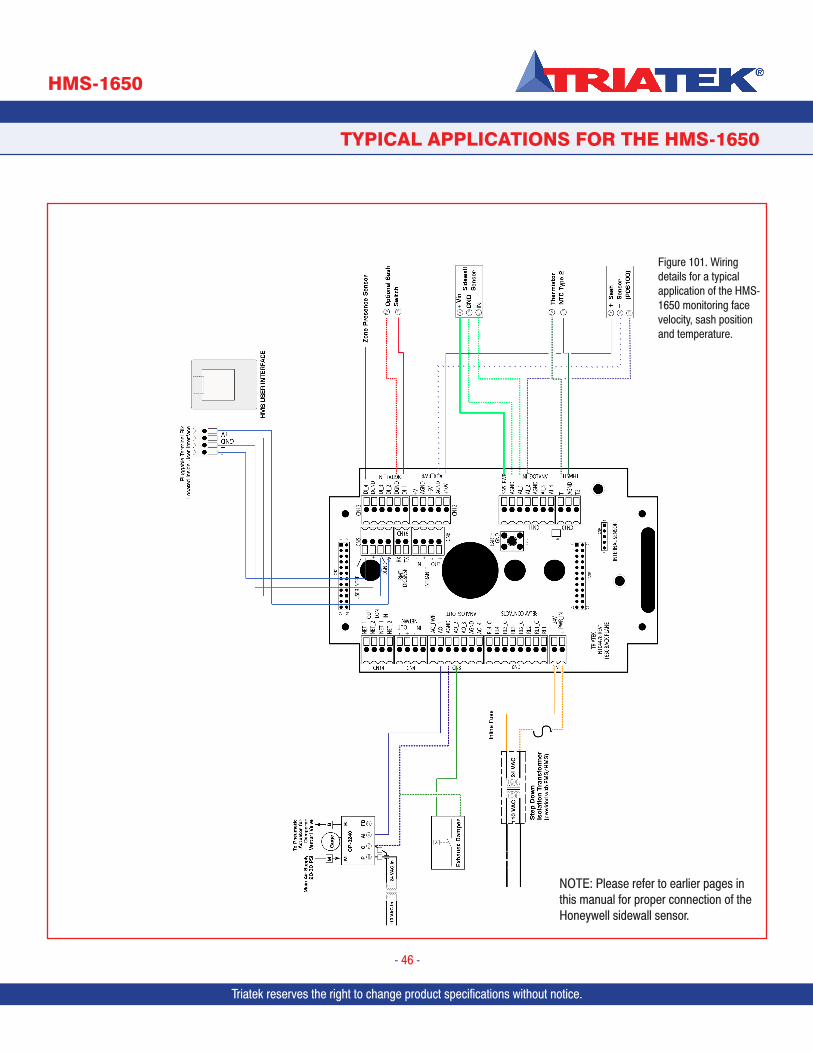
Triatek reserves the right to change product specifications without notice. Triatek reserves the right to change product specifications without notice.
TYPICAL APPLICATIONS FOR THE HMS-1650
HMS-1650
Triatek reserves the right to change product specifications without notice.
- 46 -
Figure 101. Wiring details for a typical application of the HMS-1650 monitoring face velocity, sash position and temperature.
NOTE: Please refer to earlier pages in this manual for proper connection of the Honeywell sidewall sensor.

Triatek reserves the right to change product specifications without notice.
Notes
- 47 -
TYPICAL APPLICATIONS FOR THE HMS-1650
HMS-1650
Triatek reserves the right to change product specifications without notice.
Triatek reserves the right to change product specifications without notice.
Appendix A:HMS-1650 Programmer’s Guide
Triatek reserves the right to change product specifications without notice.
- A-1 -
PID TUTORIAL
HMS-1650
Triatek reserves the right to change product specifications without notice.Triatek reserves the right to change product specifications without notice.
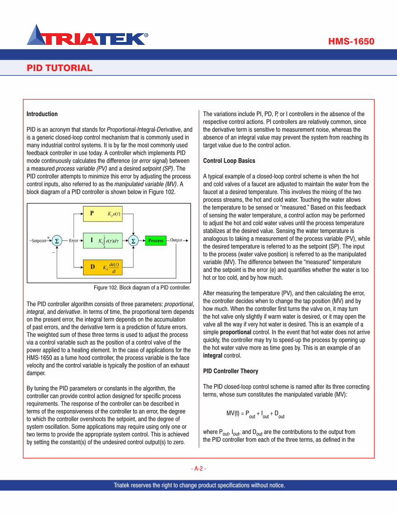
Triatek reserves the right to change product specifications without notice.
PID TUTORIAL
HMS-1650
Triatek reserves the right to change product specifications without notice.
- A-2 -
Introduction
PID is an acronym that stands for Proportional-Integral-Derivative, and is a generic closed-loop control mechanism that is commonly used in many industrial control systems. It is by far the most commonly used feedback controller in use today. A controller which implements PID mode continuously calculates the difference (or error signal) between a measured process variable (PV) and a desired setpoint (SP). The PID controller attempts to minimize this error by adjusting the process control inputs, also referred to as the manipulated variable (MV). A block diagram of a PID controller is shown below in Figure 102.
The PID controller algorithm consists of three parameters: proportional, integral, and derivative. In terms of time, the proportional term depends on the present error, the integral term depends on the accumulation of past errors, and the derivative term is a prediction of future errors. The weighted sum of these three terms is used to adjust the process via a control variable such as the position of a control valve of the power applied to a heating element. In the case of applications for the HMS-1650 as a fume hood controller, the process variable is the face velocity and the control variable is typically the position of an exhaust damper.
By tuning the PID parameters or constants in the algorithm, the controller can provide control action designed for specific process requirements. The response of the controller can be described in terms of the responsiveness of the controller to an error, the degree to which the controller overshoots the setpoint, and the degree of system oscillation. Some applications may require using only one or two terms to provide the appropriate system control. This is achieved by setting the constant(s) of the undesired control output(s) to zero.
The variations include PI, PD, P, or I controllers in the absence of the respective control actions. PI controllers are relatively common, since the derivative term is sensitive to measurement noise, whereas the absence of an integral value may prevent the system from reaching its target value due to the control action.
Control Loop Basics
A typical example of a closed-loop control scheme is when the hot and cold valves of a faucet are adjusted to maintain the water from the faucet at a desired temperature. This involves the mixing of the two process streams, the hot and cold water. Touching the water allows the temperature to be sensed or “measured.” Based on this feedback of sensing the water temperature, a control action may be performed to adjust the hot and cold water valves until the process temperature stabilizes at the desired value. Sensing the water temperature is analogous to taking a measurement of the process variable (PV), while the desired temperature is referred to as the setpoint (SP). The input to the process (water valve position) is referred to as the manipulated variable (MV). The difference between the “measured” temperature and the setpoint is the error (e) and quantifies whether the water is too hot or too cold, and by how much.
After measuring the temperature (PV), and then calculating the error, the controller decides when to change the tap position (MV) and by how much. When the controller first turns the valve on, it may turn the hot valve only slightly if warm water is desired, or it may open the valve all the way if very hot water is desired. This is an example of a simple proportional control. In the event that hot water does not arrive quickly, the controller may try to speed-up the process by opening up the hot water valve more as time goes by. This is an example of an integral control.
PID Controller Theory
The PID closed-loop control scheme is named after its three correcting terms, whose sum constitutes the manipulated variable (MV):
MV(t) = Pout + Iout + Dout
where Pout, Iout, and Dout are the contributions to the output from the PID controller from each of the three terms, as defined in the
Figure 102. Block diagram of a PID controller.
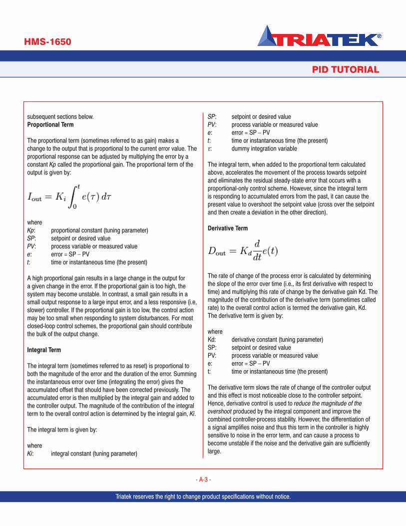
Triatek reserves the right to change product specifications without notice. Triatek reserves the right to change product specifications without notice.
PID TUTORIAL
HMS-1650
Triatek reserves the right to change product specifications without notice.
- A-3 -
subsequent sections below.Proportional Term
The proportional term (sometimes referred to as gain) makes a change to the output that is proportional to the current error value. The proportional response can be adjusted by multiplying the error by a constant Kp called the proportional gain. The proportional term of the output is given by:
where Kp: proportional constant (tuning parameter)SP: setpoint or desired valuePV: process variable or measured valuee: error = SP – PVt: time or instantaneous time (the present)
A high proportional gain results in a large change in the output for a given change in the error. If the proportional gain is too high, the system may become unstable. In contrast, a small gain results in a small output response to a large input error, and a less responsive (i.e, slower) controller. If the proportional gain is too low, the control action may be too small when responding to system disturbances. For most closed-loop control schemes, the proportional gain should contribute the bulk of the output change.
Integral Term
The integral term (sometimes referred to as reset) is proportional to both the magnitude of the error and the duration of the error. Summing the instantaneous error over time (integrating the error) gives the accumulated offset that should have been corrected previously. The accumulated error is then multiplied by the integral gain and added to the controller output. The magnitude of the contribution of the integral term to the overall control action is determined by the integral gain, Ki.
The integral term is given by: where Ki: integral constant (tuning parameter)
SP: setpoint or desired valuePV: process variable or measured valuee: error = SP – PVt: time or instantaneous time (the present)τ: dummy integration variable
The integral term, when added to the proportional term calculated above, accelerates the movement of the process towards setpoint and eliminates the residual steady-state error that occurs with a proportional-only control scheme. However, since the integral term is responding to accumulated errors from the past, it can cause the present value to overshoot the setpoint value (cross over the setpoint and then create a deviation in the other direction).
Derivative Term
The rate of change of the process error is calculated by determining the slope of the error over time (i.e., its first derivative with respect to time) and multiplying this rate of change by the derivative gain Kd. The magnitude of the contribution of the derivative term (sometimes called rate) to the overall control action is termed the derivative gain, Kd.The derivative term is given by: where Kd: derivative constant (tuning parameter)SP: setpoint or desired valuePV: process variable or measured valuee: error = SP – PVt: time or instantaneous time (the present)
The derivative term slows the rate of change of the controller output and this effect is most noticeable close to the controller setpoint. Hence, derivative control is used to reduce the magnitude of the overshoot produced by the integral component and improve the combined controller-process stability. However, the differentiation of a signal amplifies noise and thus this term in the controller is highly sensitive to noise in the error term, and can cause a process to become unstable if the noise and the derivative gain are sufficiently large.
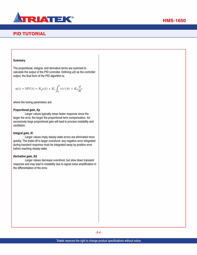
PID TUTORIAL
HMS-1650
Triatek reserves the right to change product specifications without notice.
- A-4 -
Summary
The proportional, integral, and derivative terms are summed to calculate the output of the PID controller. Defining u(t) as the controller output, the final form of the PID algorithm is:
where the tuning parameters are:
Proportional gain, Kp Larger values typically mean faster response since the larger the error, the larger the proportional term compensation. An excessively large proportional gain will lead to process instability and oscillation.
Integral gain, Ki Larger values imply steady-state errors are eliminated more quickly. The trade-off is larger overshoot: any negative error integrated during transient response must be integrated away by positive error before reaching steady-state.
Derivative gain, Kd Larger values decrease overshoot, but slow down transient response and may lead to instability due to signal noise amplification in the differentiation of the error.
Triatek reserves the right to change product specifications without notice. Triatek reserves the right to change product specifications without notice.
- B-1 -
MODULE SETTINGS
HMS-1650
Appendix B:HMS-1650 Programmer’s Guide
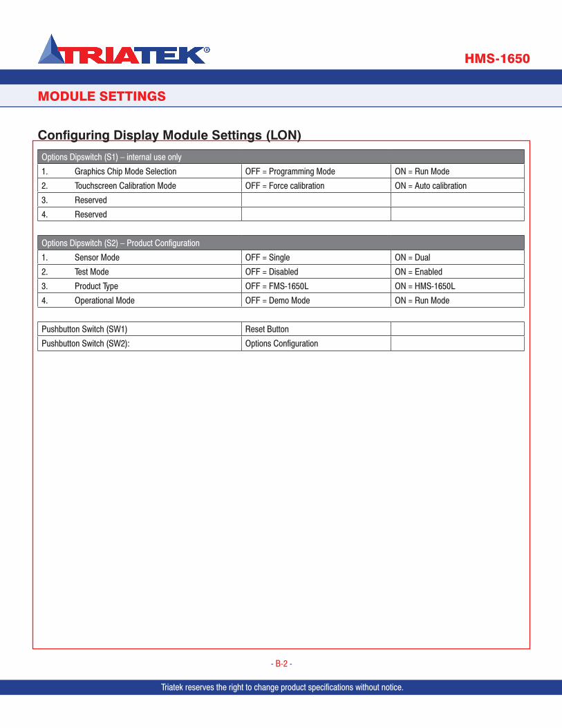
Options Dipswitch (S1) – internal use only
1. Graphics Chip Mode Selection OFF = Programming Mode ON = Run Mode
2. Touchscreen Calibration Mode OFF = Force calibration ON = Auto calibration
3. Reserved
4. Reserved
Options Dipswitch (S2) – Product Configuration
1. Sensor Mode OFF = Single ON = Dual
2. Test Mode OFF = Disabled ON = Enabled
3. Product Type OFF = FMS-1650L ON = HMS-1650L
4. Operational Mode OFF = Demo Mode ON = Run Mode
Pushbutton Switch (SW1) Reset Button
Pushbutton Switch (SW2): Options Configuration
Configuring Display Module Settings (LON)
Triatek reserves the right to change product specifications without notice.
- B-2 -
Triatek reserves the right to change product specifications without notice.
MODULE SETTINGS
HMS-1650
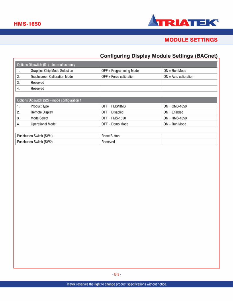
Triatek reserves the right to change product specifications without notice. Triatek reserves the right to change product specifications without notice.
Options Dipswitch (S1) – internal use only
1. Graphics Chip Mode Selection OFF = Programming Mode ON = Run Mode
2. Touchscreen Calibration Mode OFF = Force calibration ON = Auto calibration
3. Reserved
4. Reserved
Options Dipswitch (S2) – mode configuration 1
1. Product Type OFF = FMS/HMS ON = CMS-1650
2. Remote Display OFF = Disabled ON = Enabled
3. Mode Select OFF = FMS-1650 ON = HMS-1650
4. Operational Mode: OFF = Demo Mode ON = Run Mode
Pushbutton Switch (SW1): Reset Button
Pushbutton Switch (SW2): Reserved
Configuring Display Module Settings (BACnet)
Triatek reserves the right to change product specifications without notice.
- B-3 -
MODULE SETTINGS
HMS-1650
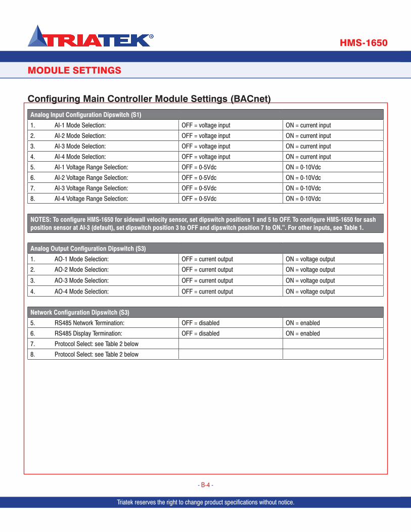
Triatek reserves the right to change product specifications without notice.
Analog Input Configuration Dipswitch (S1)
1. AI-1 Mode Selection: OFF = voltage input ON = current input
2. AI-2 Mode Selection: OFF = voltage input ON = current input
3. AI-3 Mode Selection: OFF = voltage input ON = current input
4. AI-4 Mode Selection: OFF = voltage input ON = current input
5. AI-1 Voltage Range Selection: OFF = 0-5Vdc ON = 0-10Vdc
6. AI-2 Voltage Range Selection: OFF = 0-5Vdc ON = 0-10Vdc
7. AI-3 Voltage Range Selection: OFF = 0-5Vdc ON = 0-10Vdc
8. AI-4 Voltage Range Selection: OFF = 0-5Vdc ON = 0-10Vdc
NOTES: To configure HMS-1650 for sidewall velocity sensor, set dipswitch positions 1 and 5 to OFF. To configure HMS-1650 for sash position sensor at AI-3 (default), set dipswitch position 3 to OFF and dipswitch position 7 to ON.”. For other inputs, see Table 1.
Analog Output Configuration Dipswitch (S3)
1. AO-1 Mode Selection: OFF = current output ON = voltage output
2. AO-2 Mode Selection: OFF = current output ON = voltage output
3. AO-3 Mode Selection: OFF = current output ON = voltage output
4. AO-4 Mode Selection: OFF = current output ON = voltage output
Network Configuration Dipswitch (S3)
5. RS485 Network Termination: OFF = disabled ON = enabled
6. RS485 Display Termination: OFF = disabled ON = enabled
7. Protocol Select: see Table 2 below
8. Protocol Select: see Table 2 below
Configuring Main Controller Module Settings (BACnet)
- B-4 -
Triatek reserves the right to change product specifications without notice.
MODULE SETTINGS
Triatek reserves the right to change product specifications without notice.
HMS-1650
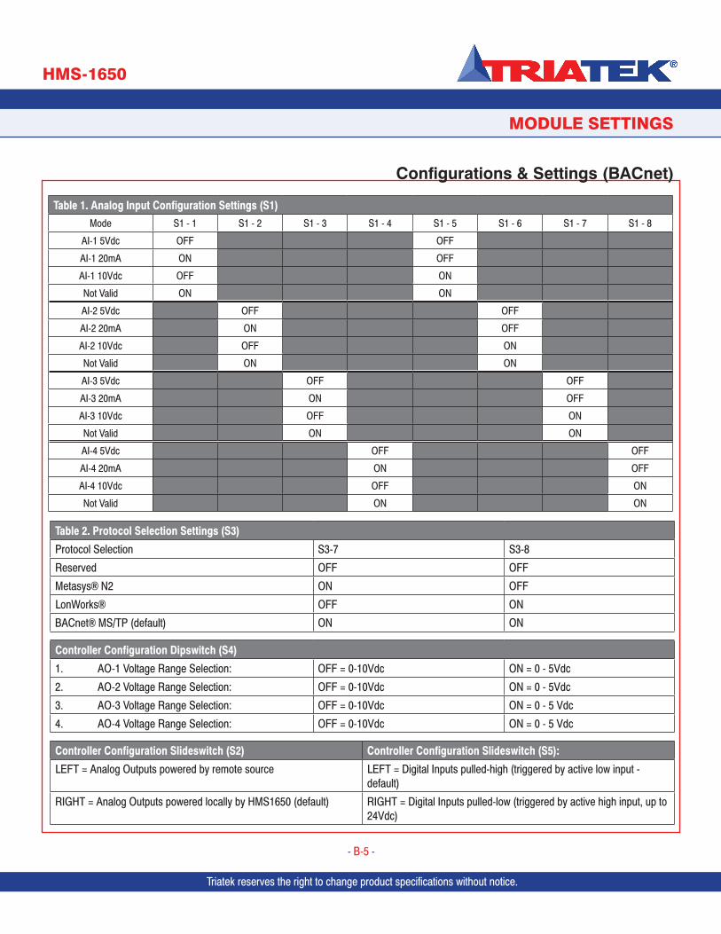
Triatek reserves the right to change product specifications without notice.
Table 1. Analog Input Configuration Settings (S1)Mode S1 - 1 S1 - 2 S1 - 3 S1 - 4 S1 - 5 S1 - 6 S1 - 7 S1 - 8
AI-1 5Vdc OFF OFF
AI-1 20mA ON OFF
AI-1 10Vdc OFF ON
Not Valid ON ON
AI-2 5Vdc OFF OFF
AI-2 20mA ON OFF
AI-2 10Vdc OFF ON
Not Valid ON ON
AI-3 5Vdc OFF OFF
AI-3 20mA ON OFF
AI-3 10Vdc OFF ON
Not Valid ON ON
AI-4 5Vdc OFF OFF
AI-4 20mA ON OFF
AI-4 10Vdc OFF ON
Not Valid ON ON
Configurations & Settings (BACnet)
Triatek reserves the right to change product specifications without notice.
- B-5 -
Triatek reserves the right to change product specifications without notice.
Table 2. Protocol Selection Settings (S3)
Protocol Selection S3-7 S3-8
Reserved OFF OFF
Metasys® N2 ON OFF
LonWorks® OFF ON
BACnet® MS/TP (default) ON ON
Controller Configuration Dipswitch (S4)
1. AO-1 Voltage Range Selection: OFF = 0-10Vdc ON = 0 - 5Vdc
2. AO-2 Voltage Range Selection: OFF = 0-10Vdc ON = 0 - 5Vdc
3. AO-3 Voltage Range Selection: OFF = 0-10Vdc ON = 0 - 5 Vdc
4. AO-4 Voltage Range Selection: OFF = 0-10Vdc ON = 0 - 5 Vdc
Controller Configuration Slideswitch (S2) Controller Configuration Slideswitch (S5):
LEFT = Analog Outputs powered by remote source LEFT = Digital Inputs pulled-high (triggered by active low input - default)
RIGHT = Analog Outputs powered locally by HMS1650 (default) RIGHT = Digital Inputs pulled-low (triggered by active high input, up to 24Vdc)
MODULE SETTINGS
Triatek reserves the right to change product specifications without notice. Triatek reserves the right to change product specifications without notice.
HMS-1650
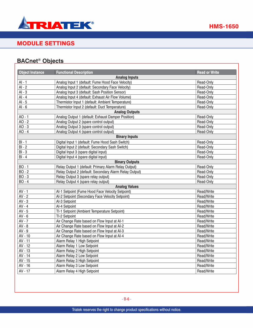
Triatek reserves the right to change product specifications without notice.
PROGRAMMER’S GUIDE
BACnet® Objects
- B-6 -
PROGRAMMER’S GUIDE
Triatek reserves the right to change product specifications without notice.
MODULE SETTINGS
Object Instance Functional Description Read or WriteAnalog Inputs
AI - 1 Analog Input 1 (default: Fume Hood Face Velocity) Read-OnlyAI - 2 Analog Input 2 (default: Secondary Face Velocity) Read-OnlyAI - 3 Analog Input 3 (default: Sash Position Sensor) Read-OnlyAI - 4 Analog Input 4 (default: Exhaust Air Flow Volume) Read-OnlyAI - 5 Thermistor Input 1 (default: Ambient Temperature) Read-OnlyAI - 6 Thermistor Input 2 (default: Duct Temperature) Read-Only
Analog OutputsAO - 1 Analog Output 1 (default: Exhaust Damper Position) Read-OnlyAO - 2 Analog Output 2 (spare control output) Read-OnlyAO - 3 Analog Output 3 (spare control output) Read-OnlyAO - 4 Analog Output 4 (spare control output) Read-Only
Binary InputsBI - 1 Digital Input 1 (default: Fume Hood Sash Switch) Read-OnlyBI - 2 Digital Input 2 (default: Secondary Sash Switch) Read-OnlyBI - 3 Digital Input 3 (spare digital input) Read-OnlyBI - 4 Digital Input 4 (spare digital input) Read-Only
Binary OutputsBO - 1 Relay Output 1 (default: Primary Alarm Relay Output) Read-OnlyBO - 2 Relay Output 2 (default: Secondary Alarm Relay Output) Read-OnlyBO - 3 Relay Output 3 (spare relay output) Read-OnlyBO - 4 Relay Output 4 (spare relay output) Read-Only
Analog ValuesAV - 1 AI-1 Setpoint (Fume Hood Face Velocity Setpoint) Read/WriteAV - 2 AI-2 Setpoint (Secondary Face Velocity Setpoint) Read/WriteAV - 3 AI-3 Setpoint Read/WriteAV - 4 AI-4 Setpoint Read/WriteAV - 5 TI-1 Setpoint (Ambient Temperature Setpoint) Read/WriteAV - 6 TI-2 Setpoint Read/WriteAV - 7 Air Change Rate based on Flow Input at AI-1 Read/WriteAV - 8 Air Change Rate based on Flow Input at AI-2 Read/WriteAV - 9 Air Change Rate based on Flow Input at AI-3 Read/WriteAV - 10 Air Change Rate based on Flow Input at AI-4 Read/WriteAV - 11 Alarm Relay 1 High Setpoint Read/WriteAV - 12 Alarm Relay 1 Low Setpoint Read/WriteAV - 13 Alarm Relay 2 High Setpoint Read/WriteAV - 14 Alarm Relay 2 Low Setpoint Read/WriteAV - 15 Alarm Relay 3 High Setpoint Read/WriteAV - 16 Alarm Relay 3 Low Setpoint Read/WriteAV - 17 Alarm Relay 4 High Setpoint Read/Write
Triatek reserves the right to change product specifications without notice.
HMS-1650
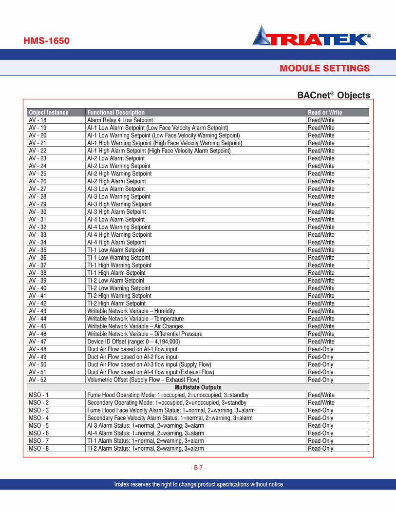
Triatek reserves the right to change product specifications without notice.
Object Instance Functional Description Read or WriteAV - 18 Alarm Relay 4 Low Setpoint Read/WriteAV - 19 AI-1 Low Alarm Setpoint (Low Face Velocity Alarm Setpoint) Read/WriteAV - 20 AI-1 Low Warning Setpoint (Low Face Velocity Warning Setpoint) Read/WriteAV - 21 AI-1 High Warning Setpoint (High Face Velocity Warning Setpoint) Read/WriteAV - 22 AI-1 High Alarm Setpoint (High Face Velocity Alarm Setpoint) Read/WriteAV - 23 AI-2 Low Alarm Setpoint Read/WriteAV - 24 AI-2 Low Warning Setpoint Read/WriteAV - 25 AI-2 High Warning Setpoint Read/WriteAV - 26 AI-2 High Alarm Setpoint Read/WriteAV - 27 AI-3 Low Alarm Setpoint Read/WriteAV - 28 AI-3 Low Warning Setpoint Read/WriteAV - 29 AI-3 High Warning Setpoint Read/WriteAV - 30 AI-3 High Alarm Setpoint Read/WriteAV - 31 AI-4 Low Alarm Setpoint Read/WriteAV - 32 AI-4 Low Warning Setpoint Read/WriteAV - 33 AI-4 High Warning Setpoint Read/WriteAV - 34 AI-4 High Alarm Setpoint Read/WriteAV - 35 TI-1 Low Alarm Setpoint Read/WriteAV - 36 TI-1 Low Warning Setpoint Read/WriteAV - 37 TI-1 High Warning Setpoint Read/WriteAV - 38 TI-1 High Alarm Setpoint Read/WriteAV - 39 TI-2 Low Alarm Setpoint Read/WriteAV - 40 TI-2 Low Warning Setpoint Read/WriteAV - 41 TI-2 High Warning Setpoint Read/WriteAV - 42 TI-2 High Alarm Setpoint Read/WriteAV - 43 Writable Network Variable – Humidity Read/WriteAV - 44 Writable Network Variable – Temperature Read/WriteAV - 45 Writable Network Variable – Air Changes Read/WriteAV - 46 Writable Network Variable – Differential Pressure Read/WriteAV - 47 Device ID Offset (range: 0 – 4,194,000) Read/WriteAV - 48 Duct Air Flow based on AI-1 flow input Read-OnlyAV - 49 Duct Air Flow based on AI-2 flow input Read-OnlyAV - 50 Duct Air Flow based on AI-3 flow input (Supply Flow) Read-OnlyAV - 51 Duct Air Flow based on AI-4 flow input (Exhaust Flow) Read-OnlyAV - 52 Volumetric Offset (Supply Flow – Exhaust Flow) Read-Only
Multistate OutputsMSO - 1 Fume Hood Operating Mode: 1=occupied, 2=unoccupied, 3=standby Read/WriteMSO - 2 Secondary Operating Mode: 1=occupied, 2=unoccupied, 3=standby Read/WriteMSO - 3 Fume Hood Face Velocity Alarm Status: 1=normal, 2=warning, 3=alarm Read-OnlyMSO - 4 Secondary Face Velocity Alarm Status: 1=normal, 2=warning, 3=alarm Read-OnlyMSO - 5 AI-3 Alarm Status: 1=normal, 2=warning, 3=alarm Read-OnlyMSO - 6 AI-4 Alarm Status: 1=normal, 2=warning, 3=alarm Read-OnlyMSO - 7 TI-1 Alarm Status: 1=normal, 2=warning, 3=alarm Read-OnlyMSO - 8 TI-2 Alarm Status: 1=normal, 2=warning, 3=alarm Read-Only
PROGRAMMER’S GUIDE
BACnet® Objects
Triatek reserves the right to change product specifications without notice.
- B-7 -
Triatek reserves the right to change product specifications without notice.Triatek reserves the right to change product specifications without notice. Triatek reserves the right to change product specifications without notice.
MODULE SETTINGS
HMS-1650
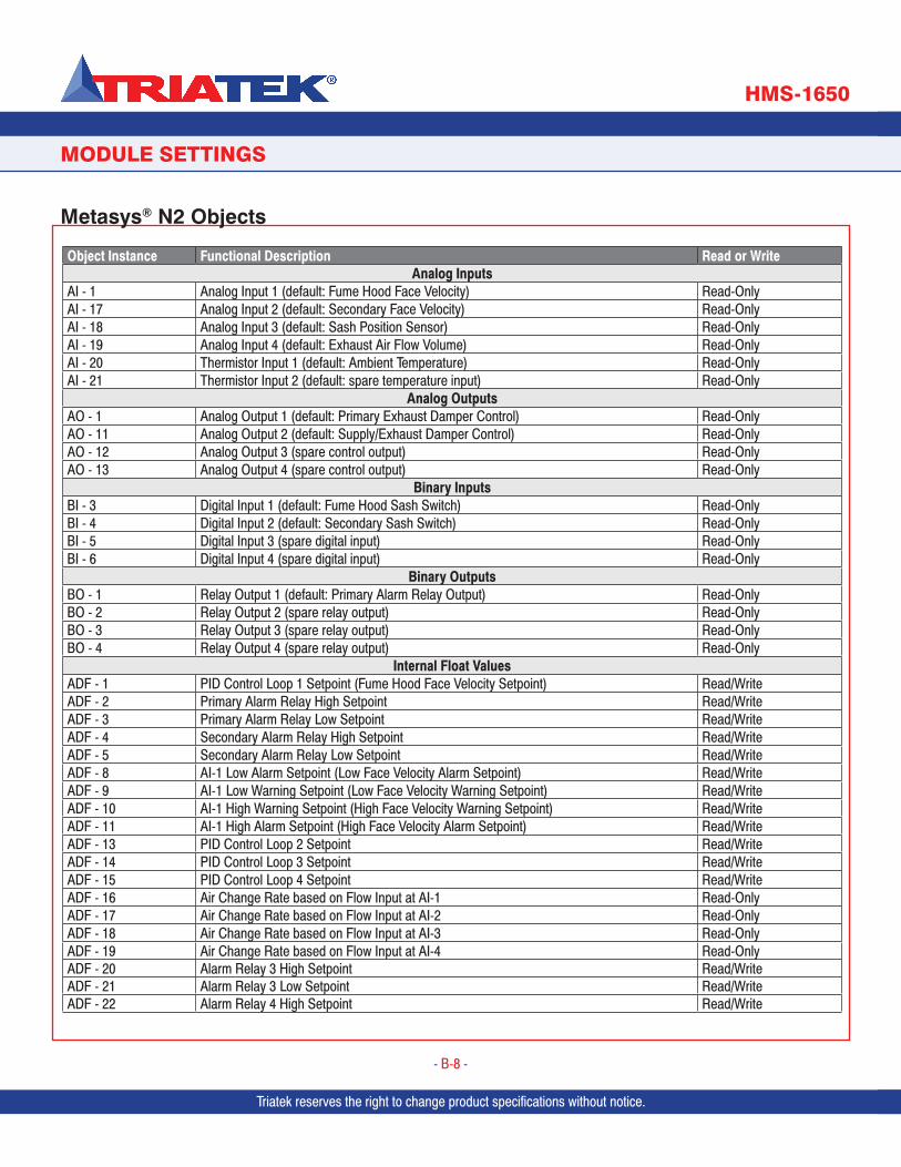
Triatek reserves the right to change product specifications without notice.
PROGRAMMER’S GUIDE
Metasys® N2 Objects
- B-8 -
PROGRAMMER’S GUIDE
Triatek reserves the right to change product specifications without notice.
MODULE SETTINGS
Object Instance Functional Description Read or WriteAnalog Inputs
AI - 1 Analog Input 1 (default: Fume Hood Face Velocity) Read-OnlyAI - 17 Analog Input 2 (default: Secondary Face Velocity) Read-OnlyAI - 18 Analog Input 3 (default: Sash Position Sensor) Read-OnlyAI - 19 Analog Input 4 (default: Exhaust Air Flow Volume) Read-OnlyAI - 20 Thermistor Input 1 (default: Ambient Temperature) Read-OnlyAI - 21 Thermistor Input 2 (default: spare temperature input) Read-Only
Analog OutputsAO - 1 Analog Output 1 (default: Primary Exhaust Damper Control) Read-OnlyAO - 11 Analog Output 2 (default: Supply/Exhaust Damper Control) Read-OnlyAO - 12 Analog Output 3 (spare control output) Read-OnlyAO - 13 Analog Output 4 (spare control output) Read-Only
Binary InputsBI - 3 Digital Input 1 (default: Fume Hood Sash Switch) Read-OnlyBI - 4 Digital Input 2 (default: Secondary Sash Switch) Read-OnlyBI - 5 Digital Input 3 (spare digital input) Read-OnlyBI - 6 Digital Input 4 (spare digital input) Read-Only
Binary OutputsBO - 1 Relay Output 1 (default: Primary Alarm Relay Output) Read-OnlyBO - 2 Relay Output 2 (spare relay output) Read-OnlyBO - 3 Relay Output 3 (spare relay output) Read-OnlyBO - 4 Relay Output 4 (spare relay output) Read-Only
Internal Float ValuesADF - 1 PID Control Loop 1 Setpoint (Fume Hood Face Velocity Setpoint) Read/WriteADF - 2 Primary Alarm Relay High Setpoint Read/WriteADF - 3 Primary Alarm Relay Low Setpoint Read/WriteADF - 4 Secondary Alarm Relay High Setpoint Read/WriteADF - 5 Secondary Alarm Relay Low Setpoint Read/WriteADF - 8 AI-1 Low Alarm Setpoint (Low Face Velocity Alarm Setpoint) Read/WriteADF - 9 AI-1 Low Warning Setpoint (Low Face Velocity Warning Setpoint) Read/WriteADF - 10 AI-1 High Warning Setpoint (High Face Velocity Warning Setpoint) Read/WriteADF - 11 AI-1 High Alarm Setpoint (High Face Velocity Alarm Setpoint) Read/WriteADF - 13 PID Control Loop 2 Setpoint Read/WriteADF - 14 PID Control Loop 3 Setpoint Read/WriteADF - 15 PID Control Loop 4 Setpoint Read/WriteADF - 16 Air Change Rate based on Flow Input at AI-1 Read-OnlyADF - 17 Air Change Rate based on Flow Input at AI-2 Read-OnlyADF - 18 Air Change Rate based on Flow Input at AI-3 Read-OnlyADF - 19 Air Change Rate based on Flow Input at AI-4 Read-OnlyADF - 20 Alarm Relay 3 High Setpoint Read/WriteADF - 21 Alarm Relay 3 Low Setpoint Read/WriteADF - 22 Alarm Relay 4 High Setpoint Read/Write
Triatek reserves the right to change product specifications without notice.
HMS-1650
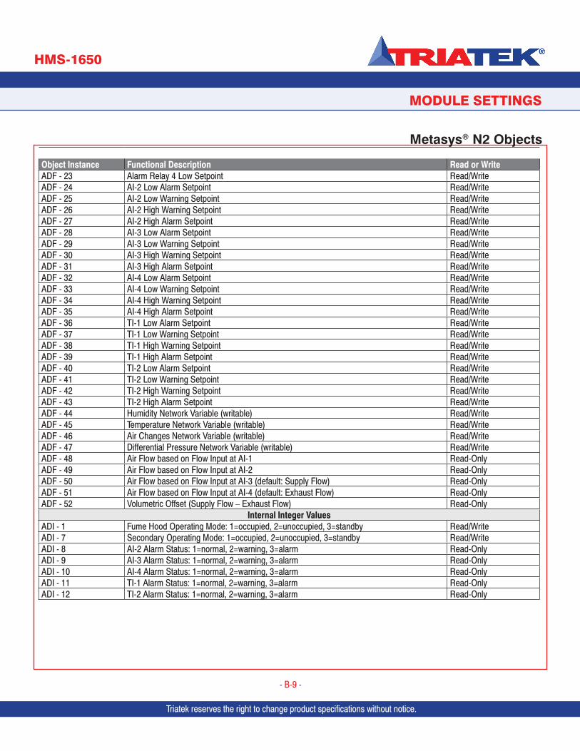
Triatek reserves the right to change product specifications without notice.
Object Instance Functional Description Read or WriteADF - 23 Alarm Relay 4 Low Setpoint Read/WriteADF - 24 AI-2 Low Alarm Setpoint Read/WriteADF - 25 AI-2 Low Warning Setpoint Read/WriteADF - 26 AI-2 High Warning Setpoint Read/WriteADF - 27 AI-2 High Alarm Setpoint Read/WriteADF - 28 AI-3 Low Alarm Setpoint Read/WriteADF - 29 AI-3 Low Warning Setpoint Read/WriteADF - 30 AI-3 High Warning Setpoint Read/WriteADF - 31 AI-3 High Alarm Setpoint Read/WriteADF - 32 AI-4 Low Alarm Setpoint Read/WriteADF - 33 AI-4 Low Warning Setpoint Read/WriteADF - 34 AI-4 High Warning Setpoint Read/WriteADF - 35 AI-4 High Alarm Setpoint Read/WriteADF - 36 TI-1 Low Alarm Setpoint Read/WriteADF - 37 TI-1 Low Warning Setpoint Read/WriteADF - 38 TI-1 High Warning Setpoint Read/WriteADF - 39 TI-1 High Alarm Setpoint Read/WriteADF - 40 TI-2 Low Alarm Setpoint Read/WriteADF - 41 TI-2 Low Warning Setpoint Read/WriteADF - 42 TI-2 High Warning Setpoint Read/WriteADF - 43 TI-2 High Alarm Setpoint Read/WriteADF - 44 Humidity Network Variable (writable) Read/WriteADF - 45 Temperature Network Variable (writable) Read/WriteADF - 46 Air Changes Network Variable (writable) Read/WriteADF - 47 Differential Pressure Network Variable (writable) Read/WriteADF - 48 Air Flow based on Flow Input at AI-1 Read-OnlyADF - 49 Air Flow based on Flow Input at AI-2 Read-OnlyADF - 50 Air Flow based on Flow Input at AI-3 (default: Supply Flow) Read-OnlyADF - 51 Air Flow based on Flow Input at AI-4 (default: Exhaust Flow) Read-OnlyADF - 52 Volumetric Offset (Supply Flow – Exhaust Flow) Read-Only
Internal Integer ValuesADI - 1 Fume Hood Operating Mode: 1=occupied, 2=unoccupied, 3=standby Read/WriteADI - 7 Secondary Operating Mode: 1=occupied, 2=unoccupied, 3=standby Read/WriteADI - 8 AI-2 Alarm Status: 1=normal, 2=warning, 3=alarm Read-OnlyADI - 9 AI-3 Alarm Status: 1=normal, 2=warning, 3=alarm Read-OnlyADI - 10 AI-4 Alarm Status: 1=normal, 2=warning, 3=alarm Read-OnlyADI - 11 TI-1 Alarm Status: 1=normal, 2=warning, 3=alarm Read-OnlyADI - 12 TI-2 Alarm Status: 1=normal, 2=warning, 3=alarm Read-Only
PROGRAMMER’S GUIDE
Metasys® N2 Objects
Triatek reserves the right to change product specifications without notice.
- B-9 -
Triatek reserves the right to change product specifications without notice.Triatek reserves the right to change product specifications without notice. Triatek reserves the right to change product specifications without notice.
MODULE SETTINGS
HMS-1650

Due to continuous improvement, TRIATEK reserves the right to change product specifications without notice.
SUBHEAD
HMS-1650
Due to continuous improvement, Triatek reserves the right to change product specifications without notice.
- B-10 -
Due to continuous improvement, Triatek reserves the right to change product specifications without notice.
FLOW DIAGRAMS
Triatek reserves the right to change product specifications without notice. Triatek reserves the right to change product specifications without notice.
Unit Setup Tree
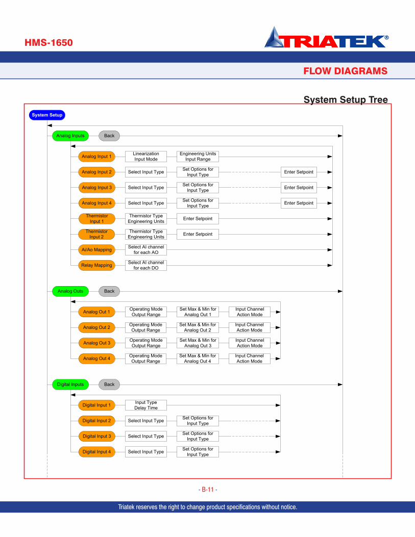
Due to continuous improvement, TRIATEK reserves the right to change product specifications without notice.Due to continuous improvement, Triatek reserves the right to change product specifications without notice.
SUBHEAD
HMS-1650
Due to continuous improvement, Triatek reserves the right to change product specifications without notice.
- B-11 -
FLOW DIAGRAMS
Triatek reserves the right to change product specifications without notice. Triatek reserves the right to change product specifications without notice.
System Setup Tree
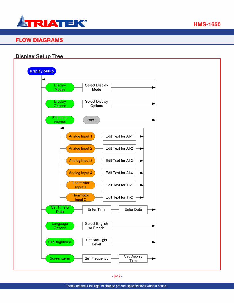
Due to continuous improvement, TRIATEK reserves the right to change product specifications without notice.
SUBHEAD
HMS-1650
Due to continuous improvement, Triatek reserves the right to change product specifications without notice.
- B-12 -
Due to continuous improvement, Triatek reserves the right to change product specifications without notice.
FLOW DIAGRAMS
Triatek reserves the right to change product specifications without notice. Triatek reserves the right to change product specifications without notice.
Display Setup Tree
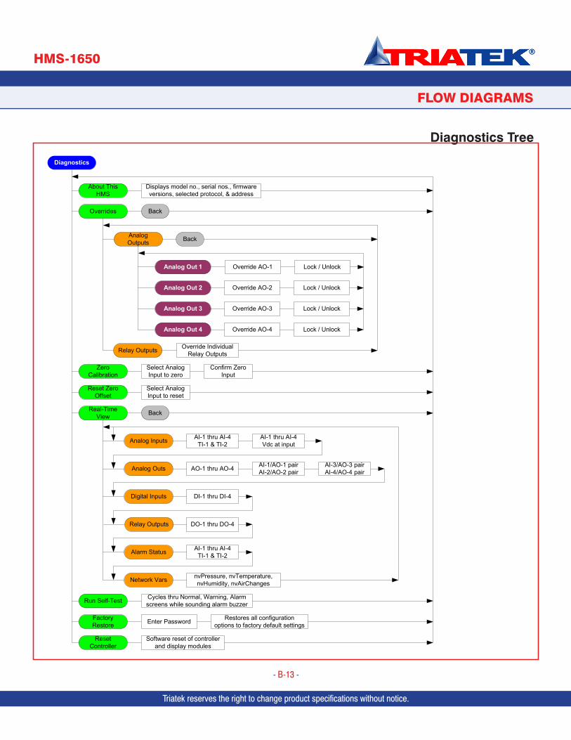
Due to continuous improvement, TRIATEK reserves the right to change product specifications without notice.Due to continuous improvement, Triatek reserves the right to change product specifications without notice.
SUBHEAD
Diagnostics Tree
HMS-1650
Due to continuous improvement, Triatek reserves the right to change product specifications without notice.
- B-13 -
FLOW DIAGRAMS
Triatek reserves the right to change product specifications without notice.

PROGRAMMER’S GUIDE
SUBHEAD
FMS-1650
Triatek reserves the right to change product specifications without notice.
- 70 -
HMS-1650
- 70 -
HMS-1650 Programmer’s Guide
Version: 03.09.17
Laboratories Classrooms Vivariums Hospitals
Triatek • 888-242-1922 or 770-242-1922 • www.triatek.com
Triatek is located in Norcross, Georgia and has an extensive network of manufacturer’s representatives located throughout North America to service you. Our helpful, experienced sales team can provide solutions for your laboratory controls, medical controls, and lighting control needs. Call 770-242-1922 or visit our website at www.triatek.com for more information or to find a representative near you.
Triatek has been a pioneer in airflow controls for over 30 years. Today, Triatek has the most complete line of controllers and monitors in the industry. Additionally, Triatek is unique in that the company engineers and sells both Venturi Valves and controllers or monitors.