Embed Size (px)
Citation preview

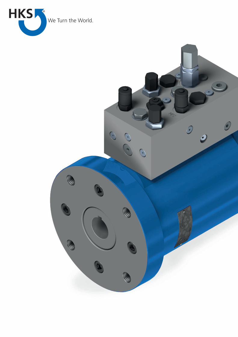
ON-/OFFSHOREHydraulic Part-Turn Actuator
www.hks-partner.com
2

We put you in the best position
We have developed the rotary actuators presented here, which have proven their worth through many years of use, especially for fittings, butterfly valves and ball valves.
The highest safety and quality demands as well as longevity and precision are typical features of HKS ro-tary actuators. Our strengths also include ATEX, DIN
standards or special customised solutions.
Wherever materials need to be rotated and tilted, pre-
cisely accelerated, braked, positioned and held, HKS
products are there to help you get the job done – with
great precision and endurance. We see the “made
in Germany” seal as the highest standard and the
yardstick for the quality of our products at the same
time. Innovation is an integral part of everything we
do, which is an advantage for you, as with HKS pro-
ducts you can always be sure of working with state-
of-the-art technology. HKS has its own development
department and manufactures practically every part
in-house, enabling us to provide you with everything
you need in outstanding quality.
The outstanding quality of our rotary actuators is in-
ternationally recognised and based on our innovative
developments, the use of best-quality materials, and
production with utmost precision. We achieve opti-
mum results for use all sectors.
We Turn the World for You
33
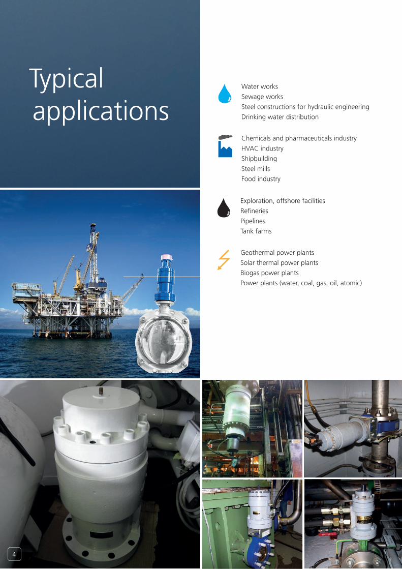
Typical applications
Water works
Sewage works
Steel constructions for hydraulic engineering
Drinking water distribution
Chemicals and pharmaceuticals industry
HVAC industry
Shipbuilding
Steel mills
Food industry
Geothermal power plants
Solar thermal power plants
Biogas power plants
Power plants (water, coal, gas, oil, atomic)
Exploration, offshore facilities
Refineries
Pipelines
Tank farms
4

The oil pressure which is supplied through connections P1 and P2 causes a rotary movement on the actuator shaft. The linear movement of the piston C is converted into a rotary movement by means of multiple gears. (Sectional representation as from the series SA-H 125)
A-A
A
A
Maßstab: Gewicht: -
Werkstoff:
Benennung:
DrehantriebSA-H 160 90° SWIG,WV,HWP,ATEX S5225
Artikelnummer 2: Artikelnummer:
Antrieb für Katalog S5225
1053468Blatt
A3CAD-Nr:.D:\Vault_lokal\Inventor\D-160\2516\Antrieb für Katalog S5225.idw
2 /2
Schutzvermerk DIN ISO 16016 beachten
Zul. Abweich. DIN ISO
2768-m-T1 T2
Oberfl. Reihe 3DIN 3141/
DIN ISO 1302
HKS UnternehmensgruppeLeipzigerstrasse 53-55D-63607 Wächtersbach
Index Änderung Datum Name Ursprung:
Datum NameGezeichnet
Kontrolliert14.11.2012 Kern
Projektions-methode 1
1 : 3
S
A Teilkreis 25.04.12 Kern
-0,1+0,1
Kantengebrochen
RHKS
0,715mm/1°
X
002003 010
009012
011
004005
006
007 008
P1 P2
C G2 G1
Functional description
With pressure at P1 the actuator shaft rotates, from the basic position to the left (anti clockwise). Chan-ges in the direction can be especially made to order.
55
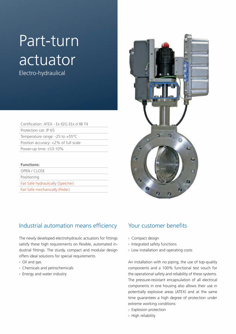
Certification: ATEX - Ex II2G EEx d IIB T4
Protection cat: IP 65
Temperature range: -25 to +55°C
Position accuracy: <2% of full scale
Power-up time: ≤S3-10%
Functions:
OPEN / CLOSE
Positioning
Fail Safe hydraulically (Speicher)
Fail Safe mechanically (Feder)
Industrial automation means efficiency
The newly developed electrohydraulic actuators for fittings
satisfy these high requirements on flexible, automated in-
dustrial fittings. The sturdy, compact and modular design
offers ideal solutions for special requirements
› Oil and gas
› Chemicals and petrochemicals
› Energy and water industry
Part-turn actuatorElectro-hydraulical
Your customer benefits
› Compact design
› Integrated safety functions
› Low installation and operating costs
An installation with no piping, the use of top-quality
components and a 100% functional test vouch for
the operational safety and reliability of these systems.
The pressure-resistant encapsulation of all electrical
components in one housing also allows their use in
potentially explosive areas (ATEX) and at the same
time guarantees a high degree of protection under
extreme working conditions:
› Explosion protection
› High reliability
6
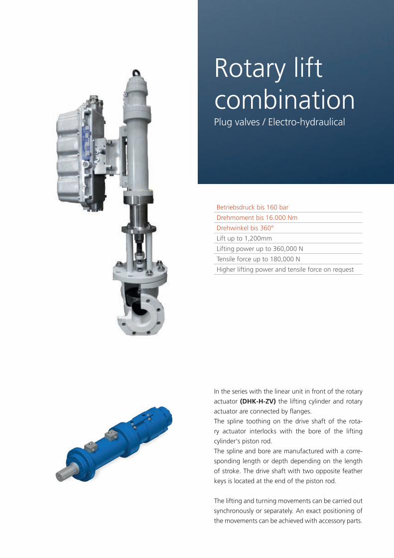
Betriebsdruck bis 160 bar
Drehmoment bis 16.000 Nm
Drehwinkel bis 360°
Lift up to 1,200mm
Lifting power up to 360,000 N
Tensile force up to 180,000 N
Higher lifting power and tensile force on request
In the series with the linear unit in front of the rotary
actuator (DHK-H-ZV) the lifting cylinder and rotary
actuator are connected by flanges.
The spline toothing on the drive shaft of the rota-
ry actuator interlocks with the bore of the lifting
cylinder‘s piston rod.
The spline and bore are manufactured with a corre-
sponding length or depth depending on the length
of stroke. The drive shaft with two opposite feather
keys is located at the end of the piston rod.
The lifting and turning movements can be carried out
synchronously or separately. An exact positioning of
the movements can be achieved with accessory parts.
Rotary lift combinationPlug valves / Electro-hydraulical
7
Hand pump
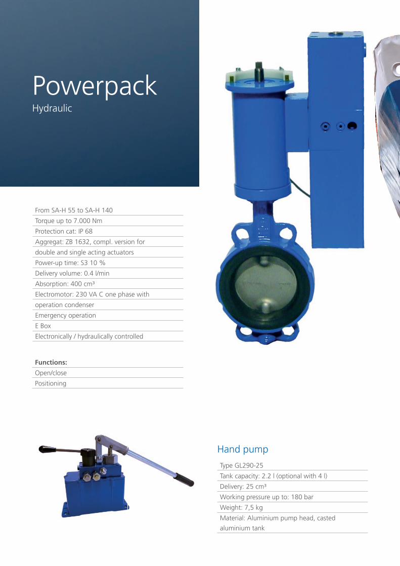
From SA-H 55 to SA-H 140
Torque up to 7.000 Nm
Protection cat: IP 68
Aggregat: ZB 1632, compl. version for
double and single acting actuators
Power-up time: S3 10 %
Delivery volume: 0.4 l/min
Absorption: 400 cm³
Electromotor: 230 VA C one phase with
operation condenser
Emergency operation
E Box
Electronically / hydraulically controlled
Type GL290-25
Tank capacity: 2.2 l (optional with 4 l)
Delivery: 25 cm³
Working pressure up to: 180 bar
Weight: 7,5 kg
Material: Aluminium pump head, casted
aluminium tank
Functions:
Open/close
Positioning
PowerpackHydraulic
8

9
up to 210 bar
Nm up to 250.000 Nm
up to 90° ±1
Temperature range: -10°C to 75°C
Protection cat: IP 65 / IP 68
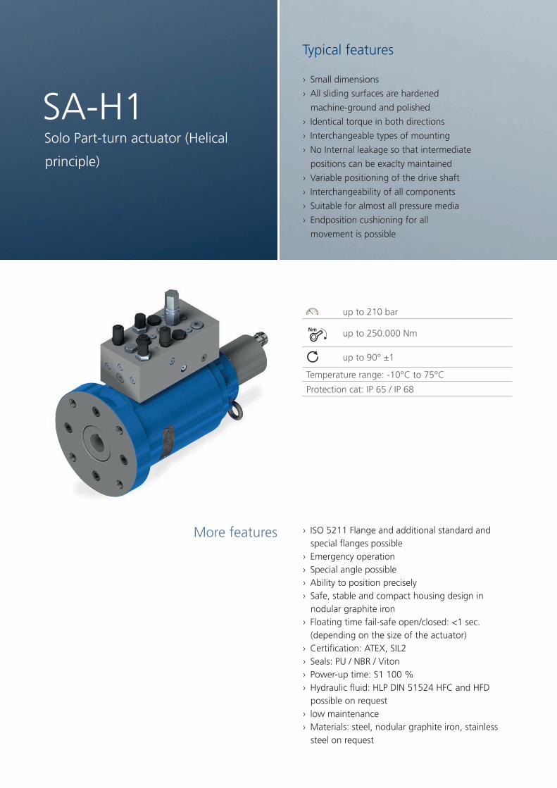
› ISO 5211 Flange and additional standard and special flanges possible
› Emergency operation › Special angle possible › Ability to position precisely › Safe, stable and compact housing design in nodular graphite iron
› Floating time fail-safe open/closed: <1 sec. (depending on the size of the actuator)
› Certification: ATEX, SIL2 › Seals: PU / NBR / Viton › Power-up time: S1 100 % › Hydraulic fluid: HLP DIN 51524 HFC and HFD possible on request
› low maintenance › Materials: steel, nodular graphite iron, stainless steel on request
More features
SA-H1Solo Part-turn actuator (Helical
principle)
Typical features
› Small dimensions
› All sliding surfaces are hardened
machine-ground and polished
› Identical torque in both directions
› Interchangeable types of mounting
› No Internal leakage so that intermediate
positions can be exaclty maintained
› Variable positioning of the drive shaft
› Interchangeability of all components
› Suitable for almost all pressure media
› Endposition cushioning for all
movement is possible
10
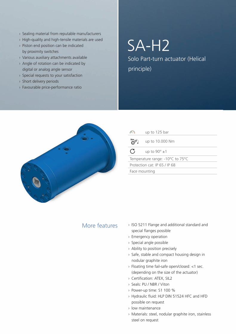
› ISO 5211 Flange and additional standard and
special flanges possible
› Emergency operation
› Special angle possible
› Ability to position precisely
› Safe, stable and compact housing design in
nodular graphite iron
› Floating time fail-safe open/closed: <1 sec.
(depending on the size of the actuator)
› Certification: ATEX, SIL2
› Seals: PU / NBR / Viton
› Power-up time: S1 100 %
› Hydraulic fluid: HLP DIN 51524 HFC and HFD
possible on request
› low maintenance
› Materials: steel, nodular graphite iron, stainless
steel on request
More features
SA-H2Solo Part-turn actuator (Helical
principle)
up to 125 bar
Nmup to 10.000 Nm
up to 90° ±1
Temperature range: -10°C to 75°C
Protection cat: IP 65 / IP 68
Face mounting
Typical features
› Sealing material from reputable manufacturers
› High-quality and high-tensile materials are used
› Piston end position can be indicated
by proximity switches
› Various auxiliary attachments available
› Angle of rotation can be indicated by
digital or analog angle sensor
› Special requests to your satisfaction
› Short delivery periods
› Favourable price-performance ratio
11

up to 350 bar
Nmup to 38.000 Nm
Spring reset single-acting
Opening moment up to 38,000 Nm
Closing moment up to 7,000 Nm
Safety function through spring reset
Part-Trun actuator spring return
You can still obtain our part-turn actuators pro-
vided with a spring return. These have been
designed for operation in a one-sided hydraulic
system. The part-turn actuator normally opens
the closed armature by hydraulic pressure and
it closes with a spring return. The opposite is
achieved with appropriate assembly. Depen-
ding on the assembly the ‘open’ or ‘closed’
position can be maintained. Specific customer
requirements are taken into account here.
AFRHydraulic / Spring Return
› Schließmoment bis zu 11.000 Nm
› Sonderwinkel möglich
› ISO-Flansch 5211
› Weitere Norm-/Sonderflansche möglich
› Zertifizierung: ATEX, SIL2
› Dichtungen: PU / NBR / Viton
› Genaue Positionierbarkeit
› Wartungsarm
› Schutzart: IP65, IP67
› Hohlwelle Vierkant
› Hohlwelle Zweikant
› Hohlwelle mit 1 Paßfedernut
› Hohlwelle mit 2 Paßfedernuten
› Notbetätigung
More features
12

13
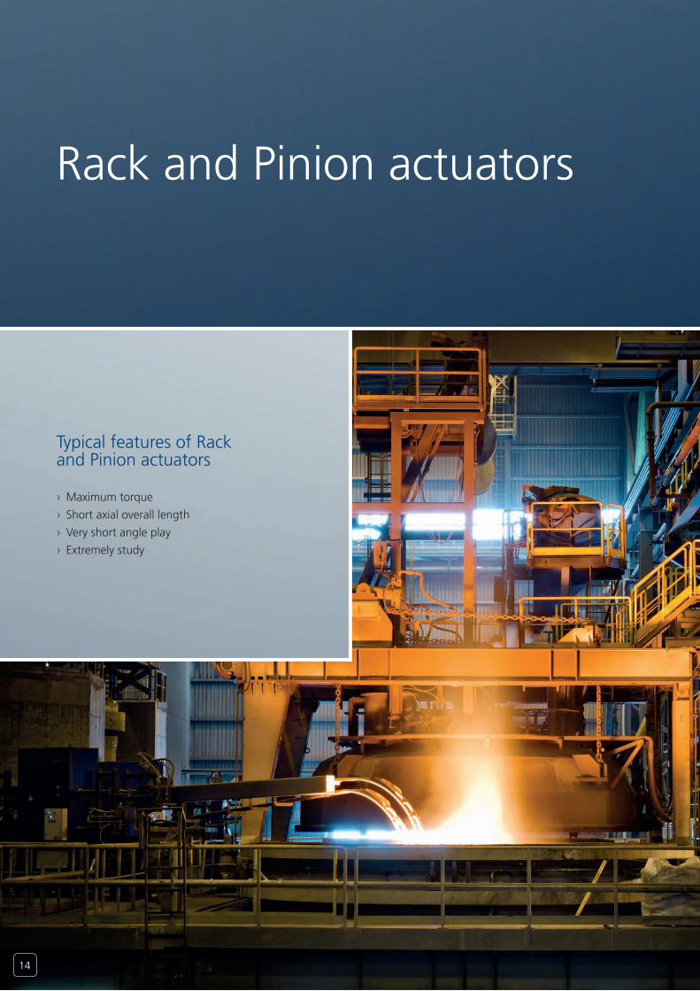
Rack and Pinion actuators
Typical features of Rack and Pinion actuators
› Maximum torque
› Short axial overall length
› Very short angle play
› Extremely study
14

up to 210 bar
Nm up to 40.000 Nm
up to 720°
Flange or foot fixingRack and Pinion actuators
up to 250 bar
Nmup to 60.000 Nm
up to 360°
Flange or foot fixing
up to 250 bar
Nmup to 350.000 Nm
up to 360° (bigger on request)
Flange or foot fixing
DZK
DEK1
DEK
15

Typ SA-H Pmax=210bar
30 42 55 63 80 100 125
Mnom
/Pworking Nm/bar
0,3 0,95 2,1 3,0 7,2 14,7 22
Absorbtion volume cdm 0,009 0,022 0,038 0,081 0,164 0,366 0,484
Weight kg 5,6 6,9 8,2 12,0 20,6 27,7 47,0
B mm 70 114 124 128 150 178 222
0 mm 11 18 18 25 25 31 37
P mm 99 137 159 187 216 252 285
P1mm 114 157 179 208 236 272 305
S " G1/8 G1/8 G1/4 G1/4 G3/8 G3/8 G3/8
T mm 10 15 20 25 25 25 25
N mm 10 15 15 15 15 15 15
I mm 6 12 17 17 22 22 22
HWP X1H7 (max.)
mm 12 18 20 22 30 42 55
X2 12 18 18 22 28 42 50
X3 mm 4 6 6 6 8 12 16
HX mm 7,8 11,8 12,8 12,8 18,3 24,3 31,8
HWV SW V (max.)
mm 31 39 45 45 75 100 120
HV 30 35 45 45 65 80 110
HWZ SW Z (max.)
mm 12 17 18 22 27 36 50
Z1 11 17 17 22 27 36 46
HZmm 34 34 45 45 50 50 50
mm 16 19 24 29 38 48 48
HWZ SW Z (max.)
mm 10 12 14 17 22 30 36
mm* 9 11 14 17 22 27 36
Z1 mm 17 24 25 25 36 50 71
HZmm 34 34 45 48 50 64 64
mm* 19 30 34 48 48 64 64
*) Dimensions acc. DIN ISO 5211
Ansicht/ view X
C
NP*
*
BT P1
HX,HV o. HZ
I
O
*
x,v o. Z
XS
*
Ansicht/ view X
C
NP*
*
BT P1
HX,HV o. HZ
I
O
*
x,v o. Z
XS
*
Mark open / closed
Technical data
View
16
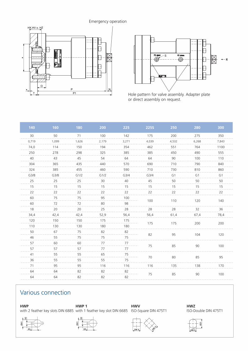
140 160 180 200 225 225S 250 280 300
30 50 71 100 142 175 200 275 350
0,719 1,099 1,626 2,179 3,271 4,039 4,532 6,268 7,843
74,0 114 150 194 354 462 551 764 1100
250 278 298 325 385 385 450 490 555
40 43 45 54 64 64 90 100 110
304 365 435 440 570 690 710 790 840
324 385 455 460 590 710 730 810 860
G3/8 G3/8 G1/2 G1/2 G3/4 G3/4 G1 G1 G1
25 25 25 30 40 45 50 50 50
15 15 15 15 15 15 15 15 15
22 22 22 22 22 22 22 22 22
60 75 75 95 100100 110 120 140
60 72 72 80 98
18 20 20 25 28 28 28 32 36
34,4 42,4 42,4 52,9 56,4 56,4 61,4 67,4 78,4
120 150 150 175 175175 175 200 200
110 130 130 180 180
50 67 75 82 8282 95 104 120
46 55 75 75 75
57 60 60 77 7775 85 90 100
57 57 57 77 77
41 55 55 65 7570 80 85 95
36 55 55 55 75
71 95 95 116 116 116 135 138 170
64 64 82 82 8275 85 90 100
64 64 82 82 82
Various connection
Ansicht/ view X
C
NP*
*
BT P1
HX,HV o. HZ
I
O
*
x,v o. Z
XS
*
Ansicht/ view X
C
NP*
*
BT P1
HX,HV o. HZ
I
O
*
x,v o. Z
XS
*
Emergency operation
HWPwith 2 feather key slots DIN 6885
HWP 1with 1 feather key slot DIN 6685
HWVISO-Square DIN 475T1
HWZISO-Double DIN 475T1
Hole pattern for valve assembly. Adapter plate or direct assembly on request.
SW V
SW V SW Z
X3
X2
ØX
1
ØZ1
X3
X2
ØX
1
SW V
SW V SW Z
X3
X2
ØX
1
ØZ1
X3
X2
ØX
1
SW V
SW V SW Z
X3
X2
ØX
1
ØZ1
X3
X2
ØX
1
SW V
SW V SW Z
X3
X2
ØX
1
ØZ1
X3
X2
ØX
1
17

14200
0
4970
9940
19880
24850
29820
210 bar100 bar0
3500
7000
10500
14000
17500
21000
210 bar100 bar
7100
0
2485
4970
9940
12425
14910
210 bar100 bar
5000
0
1750
3500
7000
8750
10500
210 bar100 bar
300
0
105
210
315300315300
420
525
630
210 bar100 bar
210
0,0
73
147
220210220210
294
367
441
210 bar100 bar
95
0
33
66
1009510095
133
166
200
210 bar100 bar
30
0
10
21
42
52
63
210 bar100 bar
3000
0
1050
2100
3150
4200
5250
6300
210 bar100 bar
2200
0
770
1540
2310220023102200
3080
3850
4620
210 bar100 bar
1470
0
514
1029
1543
2058
2572
3087
210 bar100 bar
0
12250
24500
36750
49000
61250
73500
210 bar100 bar0
9625
19250
28875
38500
48125
57750
210 bar100 bar
0
7000
14000
21000
28000
35000
42000
210 bar100 bar
17500
0
6125
12250
24500
30625
36750
210 bar100 bar
720
0
252
504
756
1008
1260
1512
210 bar100 bar
14200
0
4970
9940
19880
24850
29820
210 bar100 bar0
3500
7000
10500
14000
17500
21000
210 bar100 bar
7100
0
2485
4970
9940
12425
14910
210 bar100 bar
5000
0
1750
3500
7000
8750
10500
210 bar100 bar
300
0
105
210
420
525
630
210 bar100 bar
210
0,0
73
147
294
367
441
210 bar100 bar
95
0
33
66
133
166
200
210 bar100 bar
30
0
10
21
31303130
42
52
63
210 bar100 bar
0
1050
2100
3150
4200
5250
6300
210 bar100 bar
2200
0
770
1540
3080
3850
4620
210 bar100 bar
0
514
1029
1543
2058
2572
3087
210 bar100 bar
0
12250
24500
36750
49000
61250
73500
210 bar100 bar0
9625
19250
28875
38500
48125
57750
210 bar100 bar
0
7000
14000
21000
28000
35000
42000
210 bar100 bar
17500
0
6125
12250
24500
30625
36750
210 bar100 bar0
252
504
756
1008
1260
1512
210 bar100 bar
*at 210 bar (0,3 Nm/bar)
Nm
Nm
Nm
Nm
Nm
Nm
Nm
Nm
Nm
*at 210 bar (7,2 Nm/bar)
*at 210 bar (0,95 Nm/bar)
*at 210 bar (14,7 Nm/bar)
*at 210 bar (2,1 Nm/bar)
*at 210 bar (22 Nm/bar)
*at 210 bar (3 Nm/bar)
*at 210 bar (30 Nm/bar)
SA-H 63
SA-H 140
SA-H 55
SA-H 125
SA-H 100
SA-H 30
SA-H 80
SA-H 42
Nom. torqueto working pressure of the series
SA-H 30 to SA-H 300
18
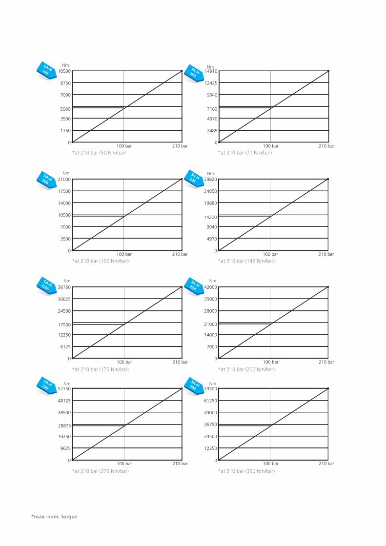
*max. nom. torque
14200
0
4970
9940
14910142001491014200
19880
24850
29820
210 bar100 bar
10000
0
3500
7000
10500
14000
17500
21000
210 bar100 bar
7100
0
2485
4970
7455710074557100
9940
12425
14910
210 bar100 bar
5000
0
1750
3500
5250500052505000
7000
8750
10500
210 bar100 bar
300
0
105
210
420
525
630
210 bar100 bar
210
0,0
73
147
294
367
441
210 bar100 bar
95
0
33
66
133
166
200
210 bar100 bar
30
0
10
21
42
52
63
210 bar100 bar
0
1050
2100
3150
4200
5250
6300
210 bar100 bar
2200
0
770
1540
3080
3850
4620
210 bar100 bar
0
514
1029
1543
2058
2572
3087
210 bar100 bar
35000
0
12250
24500
36750
49000
61250
73500
210 bar100 bar
27500
0
9625
19250
28875
38500
48125
57750
210 bar100 bar
20000
0
7000
14000
21000
28000
35000
42000
210 bar100 bar
17500
0
6125
12250
18375175001837517500
24500
30625
36750
210 bar100 bar0
252
504
756
1008
1260
1512
210 bar100 bar
*at 210 bar (50 Nm/bar)
Nm
Nm
Nm
Nm
Nm
Nm
Nm
Nm
*at 210 bar (175 Nm/bar)
*at 210 bar (71 Nm/bar)
*at 210 bar (200 Nm/bar)
*at 210 bar (100 Nm/bar)
*at 210 bar (275 Nm/bar)
*at 210 bar (142 Nm/bar)
*at 210 bar (350 Nm/bar)
SA-H 225
SA-H 300
SA-H 200
SA-H 280
SA-H 180
SA-H 250
SA-H 160
SA-H 225S
19
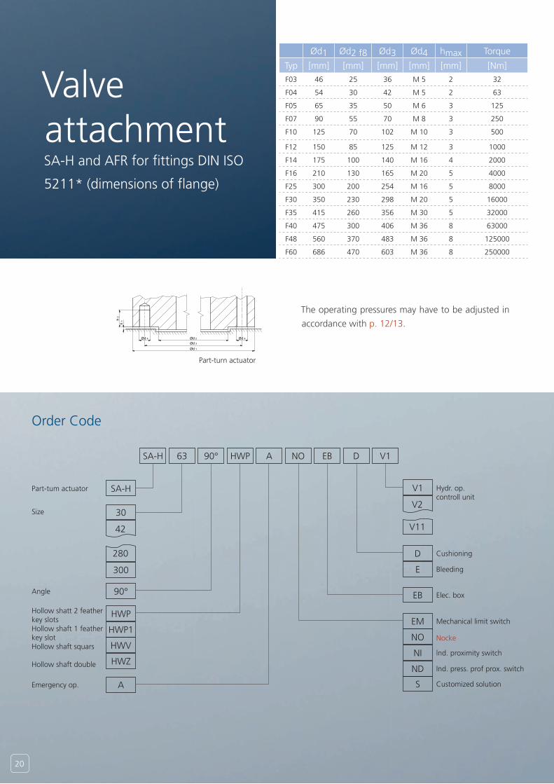
Order Code
Ød1 Ød2 f8 Ød3 Ød4 hmax Torque
Typ [mm] [mm] [mm] [mm] [mm] [Nm]
F03 46 25 36 M 5 2 32
F04 54 30 42 M 5 2 63
F05 65 35 50 M 6 3 125
F07 90 55 70 M 8 3 250
F10 125 70 102 M 10 3 500
F12 150 85 125 M 12 3 1000
F14 175 100 140 M 16 4 2000
F16 210 130 165 M 20 5 4000
F25 300 200 254 M 16 5 8000
F30 350 230 298 M 20 5 16000
F35 415 260 356 M 30 5 32000
F40 475 300 406 M 36 8 63000
F48 560 370 483 M 36 8 125000
F60 686 470 603 M 36 8 250000
A-A
B (1 : 1)
A A
B
Maßstab: Gewicht: -
Werkstoff:
Benennung:
Artikelnummer 2: Artikelnummer:
Flansch DIN ISO 5211
Blatt
A3CAD-Nr:.C:\Users\c.eichenauer\Desktop\Katalog\Flansch DIN ISO 5211.idw
1 /1
Schutzvermerk DIN ISO 16016 beachten
Zul. Abweich. DIN ISO
2768-m-T1 T2
Oberfl. Reihe 3DIN 3141/
DIN ISO 1302
HKS UnternehmensgruppeLeipzigerstrasse 53-55D-63607 Wächtersbach
Index Änderung Datum Name Ursprung:
Datum NameGezeichnet
Kontrolliert12.11.2012 Eichenauer
Projektions-methode 1
C45
-0,1+0,1
Kantengebrochen
RHKS
Ød 2Ød 4Ød 3Ød 1
h 2
h 1
Ød 4
Part-turn actuator
The operating pressures may have to be adjusted in
accordance with p. 12/13.
SA-H
SA-H V1
A90° EB63
30V2
42 V11
280 D
HWP
EB
HWVNO
300
90°
E
HWP1EM
HWZNI
A
ND
S
NOHWP D V1
Valve attachmentSA-H and AFR for fittings DIN ISO
5211* (dimensions of flange)
Size
Part-tum actuator
Angle
Hollow shatt 2 feather key slotsHollow shaft 1 feather key slotHollow shaft squars
Hollow shaft double
Emergency op.
Cushioning
Bleeding
Hydr. op. controll unit
Elec. box
Mechanical limit switch
Nocke
lnd. proximity switch
Ind. press. prof prox. switch
Customized solution
20
C-C
D (1 : 2)C
C
D
Maßstab: Gewicht: -
Werkstoff:
Benennung:
SchwenkantriebSA-H 100 90° A,HWP,F10,EM S1758
Artikelnummer 2: Artikelnummer:
251009001758 1002885Blatt
A3CAD-Nr:.C:\Users\c.eichenauer\Desktop\Katalog\S1758.idw
1 /1
Schutzvermerk DIN ISO 16016 beachten
Zul. Abweich. DIN ISO
2768-m-T1 T2
Oberfl. Reihe 3DIN 3141/
DIN ISO 1302
HKS UnternehmensgruppeLeipzigerstrasse 53-55D-63607 Wächtersbach
Index Änderung Datum Name Ursprung:
Datum NameGezeichnet
Kontrolliert14.07.2009 T.Simon
Projektions-methode 1
-0,1+0,1
Kantengebrochen
RHKS
Maßstab: Gewicht: -
Werkstoff:
Benennung:
SchwenkantriebSA-H 63 90° A,Vk17,F05,Ni S5238
Artikelnummer 2: Artikelnummer:
250609005238 1053691Blatt
A3CAD-Nr:.C:\Users\c.eichenauer\Desktop\Katalog\S5238.idw
1 /1
Schutzvermerk DIN ISO 16016 beachten
Zul. Abweich. DIN ISO
2768-m-T1 T2
Oberfl. Reihe 3DIN 3141/
DIN ISO 1302
HKS UnternehmensgruppeLeipzigerstrasse 53-55D-63607 Wächtersbach
Index Änderung Datum Name Ursprung:
Datum NameGezeichnet
Kontrolliert04.04.2012 D.Popov
Projektions-methode 1
-0,1+0,1
Kantengebrochen
RHKS
A-A
C (1 : 1,5)
A
A
C
Maßstab: Gewicht: -
Werkstoff:
Benennung:
SchwenkantriebSA-H 80 90° HWV14,F10,SWZ,E-Box S5239
Artikelnummer 2: Artikelnummer:
250809005239 1053715Blatt
A3CAD-Nr:.C:\Users\c.eichenauer\Desktop\Katalog\S5239.idw
1 /1
Schutzvermerk DIN ISO 16016 beachten
Zul. Abweich. DIN ISO
2768-m-T1 T2
Oberfl. Reihe 3DIN 3141/
DIN ISO 1302
HKS UnternehmensgruppeLeipzigerstrasse 53-55D-63607 Wächtersbach
Index Änderung Datum Name Ursprung:
Datum NameGezeichnet
Kontrolliert18.04.2012 D.Popov
Projektions-methode 1
-0,1+0,1
Kantengebrochen
RHKS
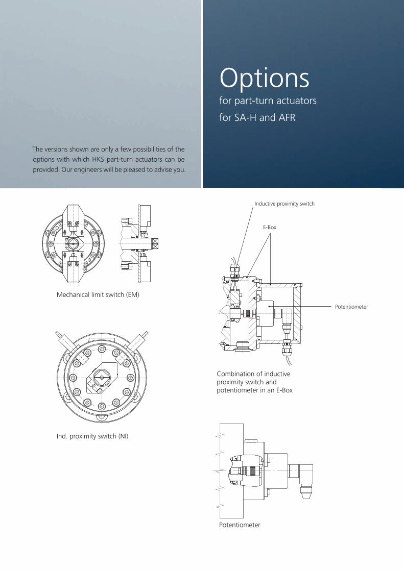
Mechanical Iimit switch (EM)
E-Box
Potentiometer
Ind. proximity switch (NI)
Inductive proximity switch
Combination of inductive proximity switch and potentiometer in an E-Box
Potentiometer
Optionsfor part-turn actuators
for SA-H and AFR
The versions shown are only a few possibilities of the
options with which HKS part-turn actuators can be
provided. Our engineers will be pleased to advise you.
21
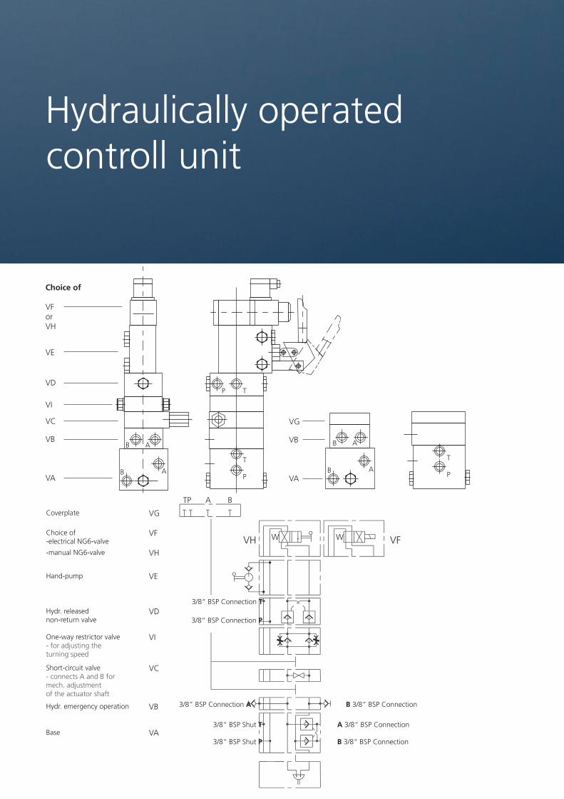
Choice of
VForVH
VE
VD
VI
VC VG
VB VB
VA
VG
TP A B
VF
VH
VH W W VF
VE
VD
VI
VC
VB
VA
VAB B
B B
A A
A A
T T
TP
P P
Hydraulically operated controll unit
Coverplate
Choice of-electrical NG6-valve
-manual NG6-valve
Hand-pump
Hydr. released non-return valve
One-way restrictor valve- for adjusting the turning speed
Short-circuit valve- connects A and B formech. adjustmentof the actuator shaft
Hydr. emergency operation
Base3/8“ BSP Shut T A 3/8“ BSP Connection
3/8“ BSP Connection A B 3/8“ BSP Connection
3/8“ BSP Shut P B 3/8“ BSP Connection
3/8“ BSP Connection T
3/8“ BSP Connection P
22

The part-turn actuarors can be operated by an ex-
ternal pump aggregate or a hand-pump. Both of
these applications are also possible if the hand pump
is intended for emergency operation. By operating
through an external aggregate there are two possi-
bilities available.
1. The valves are attached to the aggregate
2. All controlls are attachad to the part-turn actuator
In case 1, connection of the hydraulic pipes is made
by the connections A and B. A causes “turning to the
left”, B. “turning to the right”, when looking at the
shaft spigots. In addition to the base VA, the cover-
plate VG is required.
In case 2 a ring pipe for P and T from the pump ag-
gregate can supply all actuators, when using several
part-turn actuators. Here the pipes for A and B from
the aggregate to each part-turn actuator are not re-
quired. The connection of the pipes is at P and T in
the base VA.
If required the different linked blocks can be com-
bined as a vertical link.
Possibilities of attachmant for A and B:
› Hydraulic emergency operation V1=VA+VB+VG
An additional external pump can be joined either by a screw or a quick-closing coupling to the part-turn actuator.
› Mechanical emergency operation V2=VA+VC+VG
The shaft can be turned with a square key when the valve is open.
› Hydraulic and mechanical emergency operation V3=VA+VB+VC+VG
› Emergency operation with a hand-pump V4=VA+VB+VC+VG
› All possibilities V5=VA+VB+VC+VD+VE+VF+VI / V5A=VA+VB+VC+VD+VE+VH+VI
Possibilities of connections for P and T:
› Hydraulic emergency operation V6=VA+VB+VF / V6A=VA+VB+VH
An additional extemal pump can be joined by a screw or a quick-closing coupling to
the part-turn actuator. (pay attention to the right 4/3 directional valve)
› Mechanical emergency operation V7=VA+VC+VF / V7A=VA+VC+VH
The shaft can be turned with a square key when the valve is open.
› Hydraulic and mechanical emergency operation V8=VA+VB+VC+VF / V8A=VA+VB+VC+VH
› Emergency operation with a hand-pump V4=VA+VD+VE+VF / V4A=VA+VD+VE+VH
› All possibilities V5=VA+VB+VC+VD+VE+VF+VI / V5A=VA+VB+VC+VD+VE+VH+VI
23

Installation and initial operation
The drive shaft is to be aligned properly to the
counterpart to avoid exceeding the permissible
axial and radial forces. Before initial operation the
hydraulic system is to be carefully cleaned and bled.
Pressure fluid
Mineral oils in the group HLP DIN 51524 / Part 2
and VDMA Sheet 24318 are recommended. It must
be borne in mind that the viscosity is between
15 mm²/s (cSt.) and 250 mm²/s (cSt.). Hydraulic
oils HLP 16 to HLP 46 meet these conditions.
Viscosities above and below the required viscosity
in the applicable temperature range may result in
increased wear.
Flame-resistant hydraulic fluids or bio oils (HFA, HFC
and HFD) may only used with our written approval.
Filtration
It is recommended that the pressure fluid be filtered
between the pump and rotary actuator (pressure
pipe). The hydraulic unit must supply the rotary
actuator with a guaranteed oil purity according to
NAS 1638 – NAS Class 7. Recommendation filter
element: 16 VG. Purity class recommendation: ISO
4406: 1999 (22/18/14).
Operating instruction
Tightening torques for cheese head screws DIN EN ISO 4762 (12.9 + Schnorr)
On stainless screws are tightening torques’s from
the manufacture to inquire. All screws must be
lubricated.
Oilchange
A change of hydraulic oil is required and depends
on the size of the system. In smaller systems an
oil change is required at correspondingly shorter
intervals. If the hydraulic fluid is contaminated it
must be changed immediately.
Oil replacement
In the case of long oil pipes, there should be a
guarantee that 50% of the displacement will be
replaced for one complete slewing movement.
Temperature range
-10°C to +75°C
If the thermal load is higher or lower than this
range, consult the factory
Before installation
Fit the screw connections with the correct
tightening torques. Otherwise the loading capacity
of the connection will be reduced. If this is the case
the connection will loosen.
24

HK
S D
reh-
Ant
riebe
Gm
bH®
• 6
3607
Wäc
hter
sbac
h-A
ufen
au •
Ger
man
y •
fax:
+49
605
3 61
63-6
39Company: Tel.:
Name: Fax.:
Street: E-Mail:
Code / City: Web:
Project: Commission: Responsible: Date:
1 Type of valve Ball valve Flaps Other ________________
2 Various connection HWP
X3
X2
ØX
1HWP 1
X3
X2
ØX
1
HWV
SW V
HWV
SW V
HWZ
SW Z
ØZ1
2.1 Dimensions ØX1: X2: X3: SW V: SW Z: ØZ1:
3 ISO-Flange with screw:
F03
F04
F05
F07
F10
F12
F14
F16
F25
F30
F35
F40
F48
F60
with through hole:
3.1 Alternative Flange (Please attach a drawing)
4 Required nom. torque M Nm
5 Part-turn angle °
5.1 Part-turn time t s
5.2 Cycles Z day/week
6 Hydraulic plant
6.1 Effective working pressure p1 bar
6.2 Max. perm. system pressure p2 bar
6.3 Flow rate Q l/min.
6.4 Plant temperature TA °C
6.5 Surrounding temperature TU °C
6.6 Medium used
7Special conditions of use
8Conditions at working place
9Necessary properties of part-turn actuator
10 Additional equipment required
Emergency operation Cushioning
Mechanical limit switch Adjustment of the rotation angle
Induced pressure proof proximity switch Hydraulically operated control unit
Induced proximity switch SIL II
Electrical-box ATEX Class: _______________________________
Bleeding Other: ____________________________________
11 Single action spring return
Spring return load N
See 1-10
12 Recommended actuator
25

Our highly qualified designers develop efficient HKS products for their
customers, equipped with state-of-the-art hardware and software ap-
plications. In cooperation with you as our customer and with our expe-
rienced technical customer support team, we develop high-quality HKS
products tailored to suit your needs.
26

Die HKS Dreh-Antriebe GmbH®
The HKS Dreh-Antriebe GmbH is one of the world‘s
leading manufacturer of rotary actuators, tilt rota-
tors, rotary lift combinations and as well rack and
pinion rotary actuators. Besides cylinders HKS distri-
butes vane actuators and since 2012 medical training
equipment. The family business, founded in 1970
currently employs approximately 190 employees at 3
sites in Germany.
With sales partners in over 20 countries, HKS Dreh-
Antriebe GmbH is internationally oriented. The pro-
portion of sales to foreign countries is over 50%.
As a family business, HKS Dreh-Antriebe GmbH at-
taches great importance to responsible and long-
term actions. Sustainability, community involvement
and health promotion of employees in the context of
numerous health actions some of the key points in
the company‘s principles.
From a logistics viewpoint the HKS Group plant 1 is
located in the centre of the EU regionally linked to
Europe’s biggest cargo airport and also within easy
reach of the biggest freight ports of Rotterdam and
Hamburg. Our plant 2 is in a strategically convenient
location for the Eastern European market.
27
HKS Dreh-Antriebe GmbH® • Leipziger Straße 55 • 63607 Wächtersbach-Aufenau • Germany • fon: +49 6053 6163-0 • fax: +49 6053 6163-639
www.hks-partner.com
Scan me O
G facebook.com/HKSDrehAntriebe
U twitter.com/HKSDrehAntriebe
P youtube.com/HKSDrehAntriebe
B issuu.com/hks_
Copyright 2016 HKS Dreh-Antriebe GmbH®
DIN EN ISO 9001:2008 TÜV certified Illustrations similar. Information no liability assumed. Subject to alteration. Status: 09/2016