Embed Size (px)
Citation preview
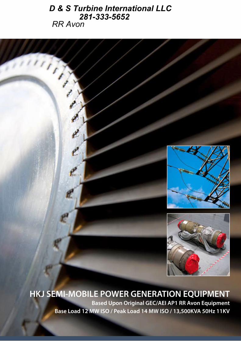
HKJ SEMI-MOBILE POWER GENERATION EQUIPMENTBased Upon Original GEC/AEI AP1 RR Avon Equipment
Base Load 12 MW ISO / Peak Load 14 MW ISO / 13,500KVA 50Hz 11KV
D & S Turbine International LLC281-333-5652
RR Avon
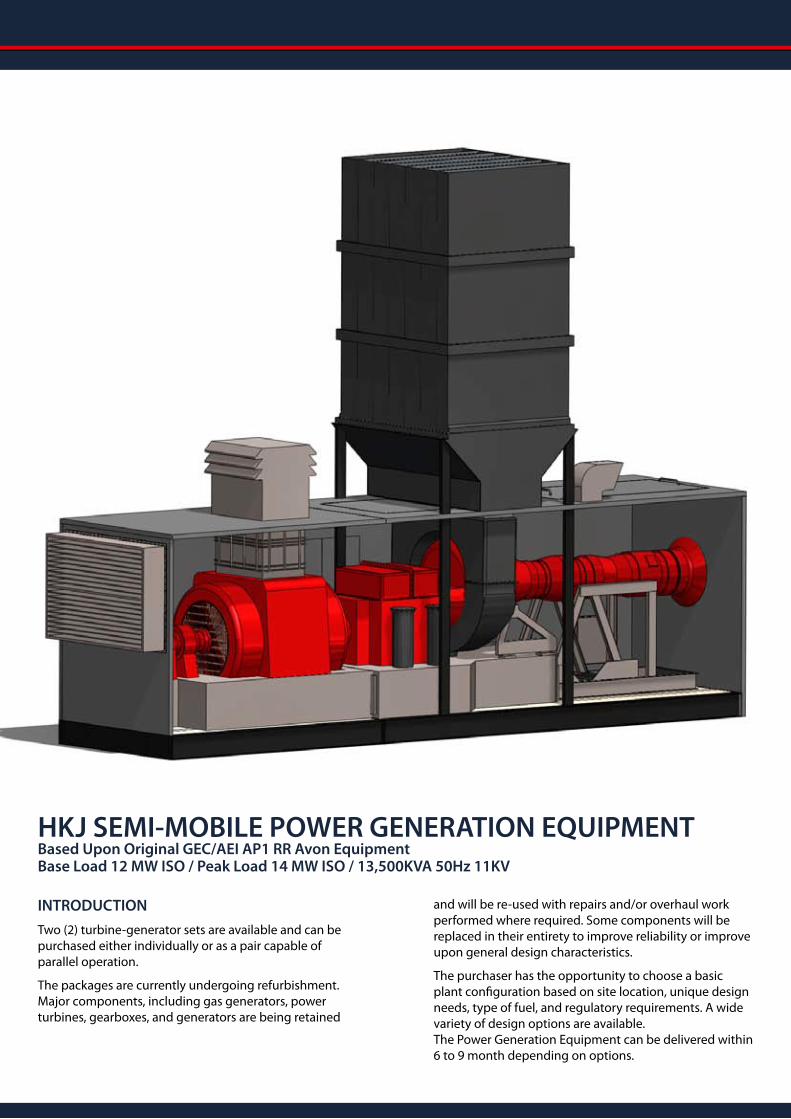
INTRODUCTION
Two (2) turbine-generator sets are available and can be purchased either individually or as a pair capable of parallel operation.
The packages are currently undergoing refurbishment. Major components, including gas generators, power turbines, gearboxes, and generators are being retained
and will be re-used with repairs and/or overhaul work performed where required. Some components will be replaced in their entirety to improve reliability or improve upon general design characteristics.
The purchaser has the opportunity to choose a basic plant configuration based on site location, unique design needs, type of fuel, and regulatory requirements. A wide variety of design options are available. The Power Generation Equipment can be delivered within 6 to 9 month depending on options.
HKJ SEMI-MOBILE POWER GENERATION EQUIPMENTBased Upon Original GEC/AEI AP1 RR Avon Equipment Base Load 12 MW ISO / Peak Load 14 MW ISO / 13,500KVA 50Hz 11KV
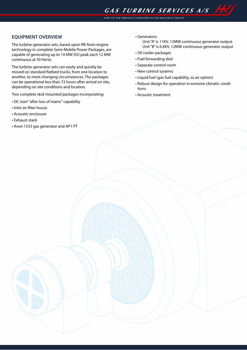
EQUIPMENT OVERVIEW
The turbine-generator sets, based upon RR Avon engine technology in complete Semi-Mobile Power Packages, are capable of generating up to 14 MW ISO peak each 12 MW continuous at 50 Hertz.
The turbine-generator sets can easily and quickly be moved on standard flatbed trucks, from one location to another, to meet changing circumstances. The packages can be operational less than 72 hours after arrival on site, depending on site conditions and location.
Two complete skid-mounted packages incorporating:
• DC start ‘’after loss of mains“ capability
• Inlet air filter house
• Acoustic enclosure
• Exhaust stack
• Avon 1533 gas generator and AP1 PT
• Generators:Unit “A” is 11KV, 12MW continuous generator output. Unit “B” is 6.6KV, 12MW continuous generator output
• Oil cooler packages
• Fuel forwarding skid
• Separate control room
• New control systems
• Liquid fuel (gas fuel capability, as an option)
• Robust design for operation in extreme climatic condi-tions
• Acoustic treatment
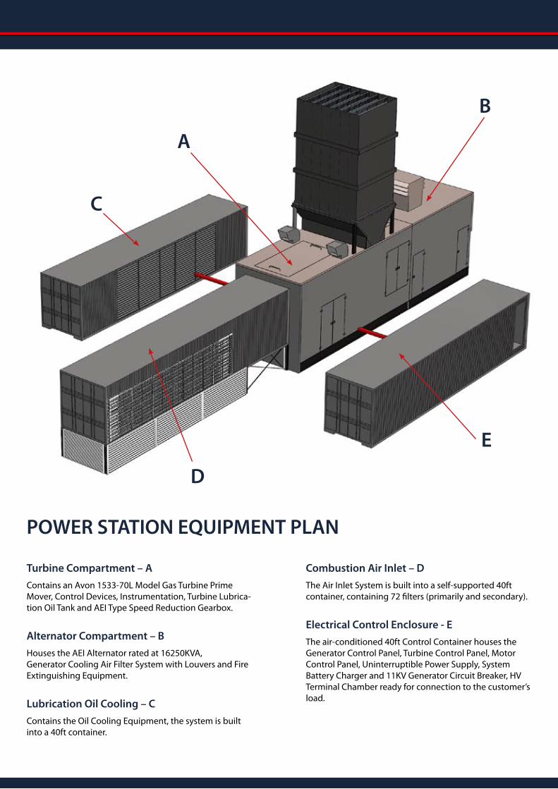
Turbine Compartment – A
Contains an Avon 1533-70L Model Gas Turbine Prime Mover, Control Devices, Instrumentation, Turbine Lubrica-tion Oil Tank and AEI Type Speed Reduction Gearbox.
Alternator Compartment – B
Houses the AEI Alternator rated at 16250KVA, Generator Cooling Air Filter System with Louvers and Fire Extinguishing Equipment.
Lubrication Oil Cooling – C
Contains the Oil Cooling Equipment, the system is built into a 40ft container.
Combustion Air Inlet – D
The Air Inlet System is built into a self-supported 40ft container, containing 72 filters (primarily and secondary).
Electrical Control Enclosure - E
The air-conditioned 40ft Control Container houses the Generator Control Panel, Turbine Control Panel, Motor Control Panel, Uninterruptible Power Supply, System Battery Charger and 11KV Generator Circuit Breaker, HV Terminal Chamber ready for connection to the customer’s load.
POWER STATION EQUIPMENT PLAN
D
A
C
B
E
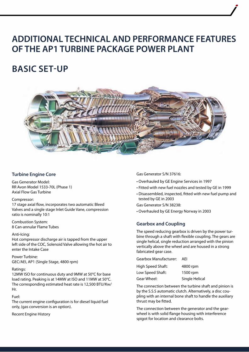
Turbine Engine Core
Gas Generator Model: RR Avon Model 1533-70L (Phase 1) Axial Flow Gas Turbine
Compressor: 17 stage axial flow, incorporates two automatic Bleed Valves and a single stage Inlet Guide Vane, compression ratio is nominally 10:1
Combustion System: 8 Can-annular Flame Tubes
Anti-Icing: Hot compressor discharge air is tapped from the upper left side of the COC, Solenoid Valve allowing the hot air to enter the Intake Case
Power Turbine: GEC/AEI, AP1 (Single Stage, 4800 rpm)
Ratings: 12MW ISO for continuous duty and 9MW at 50°C for base load rating. Peaking is at 14MW at ISO and 11MW at 50°C. The corresponding estimated heat rate is 12,500 BTU/Kw/Hr.
Fuel: The current engine configuration is for diesel liquid fuel only, (gas conversion is an option).
Recent Engine History
Gas Generator S/N 37616:
• Overhauled by GE Engine Services in 1997
• Fitted with new fuel nozzles and tested by GE in 1999
• Disassembled, inspected, fitted with new fuel pump and tested by GE in 2003
Gas Generator S/N 38238:
• Overhauled by GE Energy Norway in 2003
Gearbox and Coupling
The speed reducing gearbox is driven by the power tur-bine through a shaft with flexible coupling. The gears are single helical, single reduction arranged with the pinion vertically above the wheel and are housed in a strong fabricated gear case.
Gearbox Manufacturer: AEI
High Speed Shaft: 4800 rpm
Low Speed Shaft: 1500 rpm
Gear Wheel: Single Helical
The connection between the turbine shaft and pinion is by the S.S.S automatic clutch. Alternatively, a disc cou-pling with an internal bone shaft to handle the auxiliary thrust may be fitted.
The connection between the generator and the gear-wheel is with solid flange housing with interference spigot for location and clearance bolts.
ADDITIONAL TECHNICAL AND PERFORMANCE FEATURES OF THE AP1 TURBINE PACKAGE POWER PLANT
BASIC SET-UP
A/C Generator and Exciter
The assembly consists of a brushless AC generator, with exciter, rotating rectifier and is mounted on a rigid com-mon base plate. Generator fans draw in the cooling air through filters outside the enclosure and the
bearing oil is supplied from the gearbox lubricating system.
Main data for the Generators is as follows:
Generator No.1
Generator Manufacturer: AEI
Type: Brushless 4-pole
Ratings: 16250KVA, 0.8PF
Voltage: 11KV
Frequency: 50Hz
Shaft Speed: 1500 rpm
Cooling: Centrifugal fan mounted on the rotor shaft
Generator No.2
Generator Manufacturer: AEI
Type: Brushless 4-pole
Ratings: 14200KVA, 1.0PF
Voltage: 6.6KV
Frequency: 50Hz
Shaft Speed: 1500 rpm
Cooling: Centrifugal fan mounted on the rotor shaft
(Step-up Transformer 6,6-11KV not included)
Each unit is capable of handling full continuous power of the gas turbine at any ambient temperature throughout the specified operating range. The generator is enclosed, air cooled and is suitable for outdoor installation, in a non-hazardous environment.
Under Base
The package base frame is designed for easy moving and quick installation.
• Fabricated from carbon steel
• The Semi-Mobile Units can operate without any anchoring to a foundation
Acoustic Enclosure
The weatherproof enclosure covering the set is constructed in two main sections as follows:
• Turbine and gearbox housing
• Generator housing
Both enclosures are new, fabricated to reduce package noise to an acceptable level. Enclosures include:
• Internal lighting
• Access doors for personnel maintenance access
• Removable roof section to allow the Avon, power turbine and gearbox cover to be removed
• Acoustic enclosure ventilation inlet and outlet systems for turbine and generator compartment
Combustion Air Inlet System
The Equipment Package is supplied with a self-supported combustion air filter house built in to a new 40ft contain-er and reduces air inlet noise to an acceptable level. The Combustion Air Inlet system is mounted in front of the turbine and gearbox housing.
Special made Combustion Air Inlet filter System incorporate:
• Easy relocation and a quick set up
• Compensator and steel spacer from turbine to 40ft Inlet container
• Two Stage Filter System (primarily, secondary) replaceable dry element
Combustion Exhaust System
Exhaust gases from the power turbine passes through an insulated exhaust duct and silencer to an exhaust stack which discharges the gases into the atmosphere. The ex-haust casing is divided along the horizontal center line. It turns the gases transversely to the machine and vertically to a ‘’splitter’’ type silencer that reduces exhaust noise to an acceptable level.
The Exhaust System will incorporate:
• New Exhaust diffuser, original GEC/AEI design
• New Exhaust cone, original GEC/AEI design
• New Silencer, original GEC/AEI design
The height of the exhaust stack is approx 29 ft / 8.9 meter from ground level and is supported by the base frame.
BASIC SET-UP
Liquid Fuel System Only
The Fuel Oil System consists of an off skid fuel forward-ing system and the main systems integrated to the Avon 1533-70L (phase 1) turbine.
Fuel Forwarding System:
A new off-skid fuel forwarding system will be supplied. The forwarding system provides the turbine with liquid fuel at the appropriate pressure. The skid is contained in a sound/weather enclosure to protect the operators and equipment. Fuel is supplied from tanks or tankers (not included) and features include:
• Duplex fuel filter permitting on line duty filter replacement
• AC and DC motor driven liquid fuel boost pump
• Solenoid-operated fuel shut-off valve
• Manual emergency shut-off valve
• Pressure control valve
• Certified flow meter
Main Fuel System:
The package is mounted with Woodward Governor Control, and controls the turbine mounted mechanical fuel control unit, including:
• Low pressure filter
• High pressure fuel pump, Engine mounted
• Fuel control unit
• Throttle valve
• Woodward control
Lubricating Oil System
The Lubricating Oil System consists of two main systems, one for the Avon turbine and one for the power turbine, generator and gearbox.
Oil System for power turbine, generator and gearbox incorporates:
• Integral lubricating oil system, including all pipe work, serving the power turbine, gearbox and AC generator
• Main pump gearbox driven, delivering 225 G.P.M.
• Auxiliary pump, AC electric motor driven (pre start and post shutdown lubrication) delivering 200 G.P.M
• Emergency pump, DC electric motor driven (emergency cooling), delivering 120 G.P.M
• Lubricating oil tank integral to package underbase, capacity of 6000 Liters
• Lube oil pressure and temperature transmitters
• Oil tank level gauge
• Oil tank low oil level transmitter
• Simplex filter system with differential pressure gauge and differential pressure transmitter
• Oil breather system, including flame trap
• Lubricating oil cooler for PT, generator and gearbox
• Two air blasted lubricating oil coolers suitable for high ambient temperature range
• The oil cooler skid is built up in a new 40ft container
• Including all pipe work from oil cooler skid to the main package
Oil System for Avon Phase 1, 1533-70L Turbine incorporating:
• External oil supply tank with low oil level transmitter
• Lube oil pump, Engine mounted
• Lube oil cooler, Engine mounted
• Oil sump and filter, Engine mounted
• Relief valve, Engine mounted
• Lube oil pressure and temperature transmitters
• Oil breather, Engine mounted
Turbine Compressor Cleaning System
Cleaning System incorporating:
• Cold turbine compressor wash system
• Mobile wash trolley, incorporating: electrical AC-pump, cleaning fluid/rinse tank, fluid flexible hose with quick release connections, and electrical cable
Drain System
Drain System incorporates:
• Off-skid drain tank in stainless steel
• Drain tank high level transmitter
• Pipe work from Avon turbine to drain tank in stainless steel
Fire Protection System
A new high quality firefighting system incorporates:
• DBI approved control panel
• Detection, operation and surveillance are operated by the control panel
• The system is provided with emergency power for 30min operation, switching automatically to emergency power during power failure
• Ultra-violet flame detectors in the turbine section
• Heat detectors in the engine starter section
• Heat detectors in the generator section
• Smoke detectors in the control room
• Automatic extinguisher release and visible alarms
BASIC SET-UP
HV Generator Circuit Breaker
• Original high voltage circuit breaker and outgoing feeder (option price for new breaker)
Generator Control Panel
• New generator metering equipment
• New generator electrical protection relays
• Existing manual synchronizing controls
• Existing automatic voltage regulator
Electrical Equipment
• New AC and DC interface cabling
• New junction boxes on skid
• Integral earth protection bonding
• Emergency ‘Stop’ push-buttons externally mounted on turbine under base
• Local stop push-buttons on turbine AC motors
Motor Control Centre
• New motor control center for supply to AC and DC motors
• New motor control centre for supply to solenoids
UPS System/Batteries
New UPS is running online with “double conversion” technology with the following operation:
• AC input is filtered and then converted into DC that is used to recharge the batteries. Should a power failure occur on the AC system, the UPS design maintains emergency DC-power to the DC-controller that controls the turbine DC supply
• New maintenance free batteries are mounted within a carbon steel battery storage cabinet located externally adjacent to control room
• DC capacity for 4 start attempts after mains failure
Instrumentation
• Air inlet temperature thermocouples
• Exhaust outlet and power turbine exit temperature thermocouples
• Gas generator speed probe
• Power turbine speed probe
• Mechanical over speed protection trip
• Casing mounted seismic sensor to turbine, gearbox and driven unit
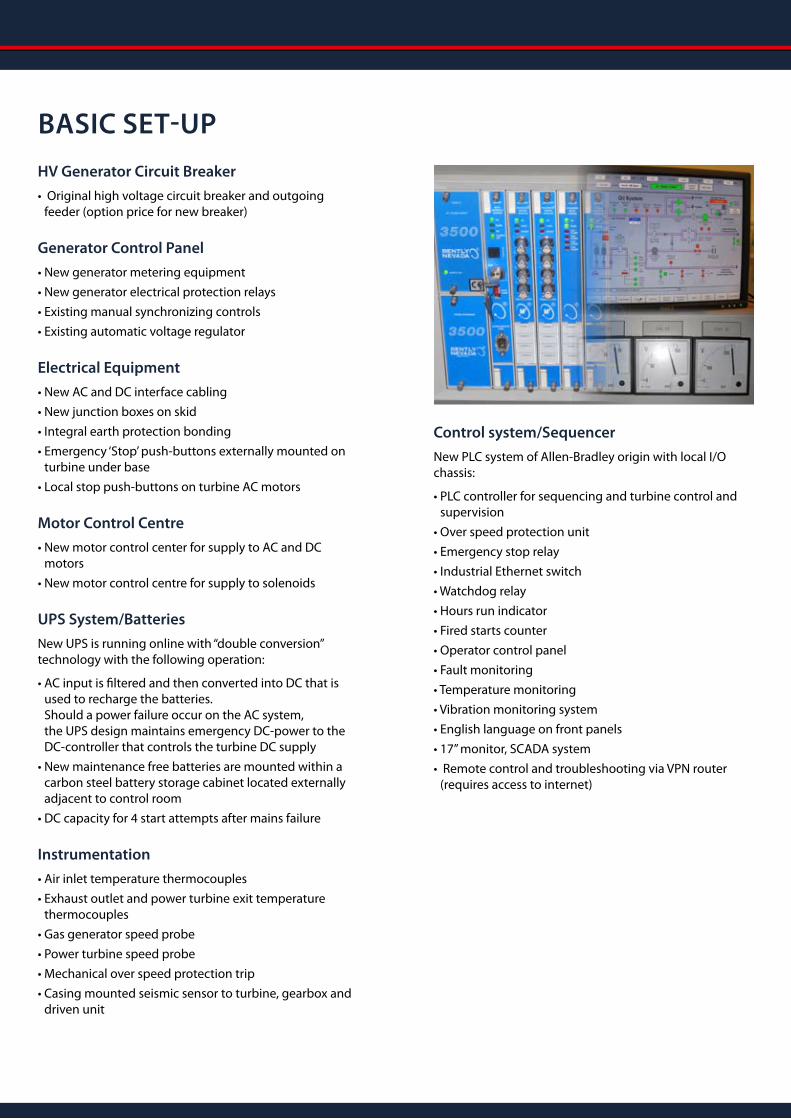
Control system/Sequencer
New PLC system of Allen-Bradley origin with local I/O chassis:
• PLC controller for sequencing and turbine control and supervision
• Over speed protection unit
• Emergency stop relay
• Industrial Ethernet switch
• Watchdog relay
• Hours run indicator
• Fired starts counter
• Operator control panel
• Fault monitoring
• Temperature monitoring
• Vibration monitoring system
• English language on front panels
• 17’’ monitor, SCADA system
• Remote control and troubleshooting via VPN router (requires access to internet)
BASIC SET-UP
Turbine Engine Core and Power Turbine
As an option the RR Avon Model 1533-70L and AP1 power turbine will be fully overhauled according to OEM specifi-cations.
For information, the rotating elements are anticipated to operate for another full overhaul cycle, under normal operating conditions, depending upon service schedules being carried out at the appropriate time, conditions of fuel, and environment and ongoing maintenance.
Gas Fuel System Only
As an option the liquid fuel can be converted to gas fuel.
Gas Fuel System conversion incorporating:
• Gas detection inside package
• Package to be converted to ATEX zone
• Turbine control conversion
• Avon 1533 conversion to gas fuel
Ventilation Silencing
If the customer has to meet strict environment require-ments, specially made low-noise ventilation is an option, which can provide average sound attenuation to 85dB (A) SPL at 1m distance measured at 1.2m above ground level.
Special low noise ventilation incorporates:
• Generator ventilation, intake and exhaust silencers
• Enclosure GT ventilation, intake and exhaust silencers
• Louvers for both systems, closes when fire occurs
Acoustic Enclosure
If a customer has to meet strict environment require-ments, a specially fabricated low noise enclosure is an option.
Fitted over the turbine, gearbox and alternator and bolted to the turbine underbase, for average sound attenuation to 85dB (A) SPL at 1m distance measured at 1.2m above ground level.
Specially made enclosure incorporates:
• Extra silencing of the enclosure
• Removable sections for maintenance access
• Access doors providing for personnel maintenance access
• Internal lighting steel construction
Note: The enclosure is custom-designed to customer requirments.
Combustion Air Inlet System
If a customer has to meet strict environment require-ments (Europe), a specially fabricated low noise Combus-tion Inlet System is an option.
Multi-stage Combustion Air Inlet Filter System, for average sound attenuation to 85dB (A) SPL at 1m distance measured at 1.2m above ground level.
Custom-designed Combustion Air Inlet Filter System incorporates:
• Three stage filter system
• Multi-stage silencer
• Inspection manhole for filter change
• Compensator and steel spacer from turbine to inlet compartment
• Extra silencing of the combustion air inlet filter system makes it easy to get authority approval in western countries
• Easy to relocate and a quick set up solution.
OPTIONS
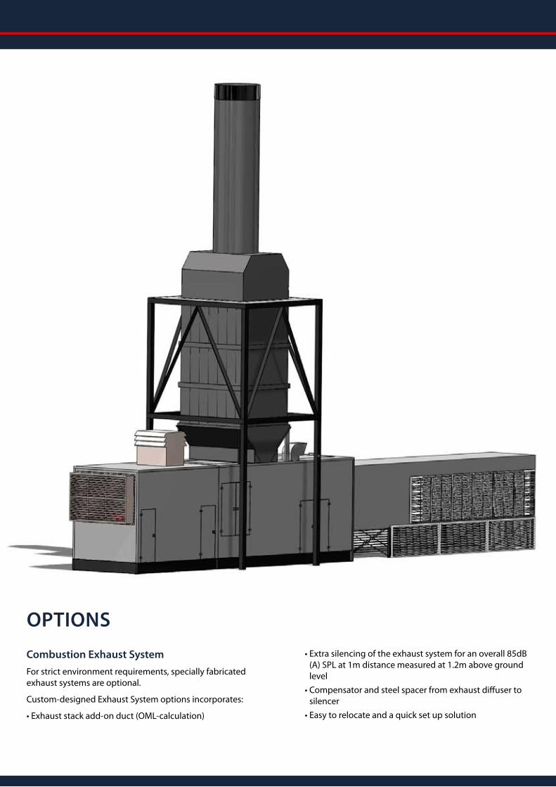
Combustion Exhaust System
For strict environment requirements, specially fabricated exhaust systems are optional.
Custom-designed Exhaust System options incorporates:
• Exhaust stack add-on duct (OML-calculation)
• Extra silencing of the exhaust system for an overall 85dB (A) SPL at 1m distance measured at 1.2m above ground level
• Compensator and steel spacer from exhaust diffuser to silencer
• Easy to relocate and a quick set up solution
OPTIONS
Black Start Capability
This system is able to start the turbine plant without an external power connection. The system comes with a suit-ably sized AC generator driven by a Perkins diesel engine.
Starter system, incorporating:
• Standard 2/4 pole electric starter motor
• Revised drive coupling
• Starter gear box arrangement
• AC starting is a simple and reliable start system
• Generator data: Olympian model – LL3014H, 165 KVA, 132 KW
• Engine data: Perkins model - 1106C-E66TAG3, 6cyl
• 3 Phase, 400V AC, 50H
Reduction of NOx emission
For strict environment requirements, Selective Catalytic Reduction (SCR) can be an option. By using the SCR tech-nology it will be possible til bring down the NOx emission to a very low level.
Glycol Lubricating Oil Coolers
For strict environment requirements, a specially fabricat-ed Oil Coolers System is an option incorporating:
• Off skid glycol system
• Secure the risk of oil spillage to the surrounding areas
• Extra silencing of the of the air blasted coolers for an overall 85dB (A) SPL at 1m distance measured at 1.2m above ground level
• Two air blasted Glycol oil coolers suitable for high ambient temperature range
• The oil cooler skid is build up in a new 40ft container
• Including all pipe work from oil cooler skid to main package
• Heat exchanger (Glycol/Oil), mounted inside turbine package
For compliance with local grid code
• Primary frequency control functions according to ENTSO-E grid code
• Block diagrams and dynamic system documentation according to IEEE Specification
Warranty
A variety of Warranty and Extended Service options are available depending on customer’s requirements.
OPTIONS
HKJ Gas Turbine Services A/S Haandvaerkervej 19, DK-6710 Esbjerg V, Telephone: (+45) 7546 8030, Fax: (+45) 7546 8077
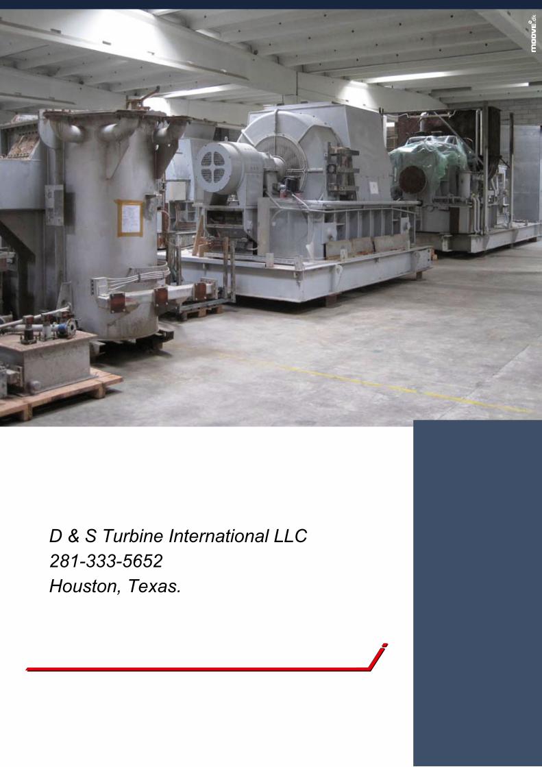
D & S Turbine International LLC281-333-5652Houston, Texas.


![WLA ]^HKJ a`bScHdQbangerth/publications/1999-deal2.pdf · WLA ]^HKJ a`bScHdQ ... iq ¿](https://img.pdfslide.us/doc/110x75/5e1e9e1d686ffe2dae388b4a/wla-hkj-abschdq-bangerthpublications1999-deal2pdf-wla-hkj-abschdq-.jpg)