Embed Size (px)
Citation preview

S99TE13-0611��
5 Specification Illustration
HIWIN manufactures ballscrews according to customers’ blueprints or specifications. Please read the following information for understanding out ballscrew designing.
1. Nominal diameter. 6. Accuracy grade (lead deviation, geometrical tolerance).
2. Thread lead. 7. Working speed.
3. Thread length, total length. 8. Maximum static load, working load, preload drag torque.
4. End journal configuration. 9. Nut safety requirements.
5. Nut configuration 10. Lubrication hole position.
HIWIN Ballscrew NomenclatureHIWIN ballscrews can be specified as follows :
1R40 - 10B2 - PFDWE2 - 800 - 1000 - 0.0035 - M
Start type1.Single start2.Double start3.Triple start4.Four start
Right hand screw
Nominal diameter
Lead
Number of turns
Preload typeP : Compression typeO : Offset typeD : High lead double startT : High lead triple startQ : High lead quatemary start
Nut shapeS : Square nutR : RoundF : Nut with flange
Note :M : StainlessH : Hollow Shaft
Lead deviation inrandom 300mm travel path thread length
Total length
Thread length
Optional Functions :E2 : Self-lubricationR1 : Rotating NutC1,C2 : Cool Type
Circulation typeW : Tubes within nut bodyV : Tubes above nut bodyB : Bonded tubeI : Internal capH : End capC : Super S series
Nut typeS : Single nutD : Double nut
Number of turns
A : 1.5, B: 2.5, C: 3.5 T3 : 3 S1 : 1.8x1 U1 : 2.8x1 K2 : 2
A2 : 1.5x2 T4 : 4 S2 : 1.8x2 U2 : 2.8x2 K3 : 3
B2 : 2.5x2 T5 : 5 S4 : 1.8x4 V2 : 0.7x2 K4 : 4
C1 : 3.5x1 T6 : 6
Note : 1. Different diameters and leads are available upon request. 2. Right hand thread is standard, left hand thread is available upon request. 3. Longer lengths are available upon request. 4. Stainless steel is available upon request, only if the ball size is less than 2.381 mm. 5. Complete questionnaire on page 170~171 and consult with HIWIN engineers. 6. If you need to order DIN 69051 type, please mark “DIN”. 7. Number of turns = turns per circuit x number of circuits. Please refer to page 6 for detailed illustration.

S99TE13-0611 ��
6 Precision Ground Ballscrews
6.1 Ground Ballscrew Series
page General Type page
39
41
Flange end, single nut,tube above the nut diameter
Flange end, single nut,tube within the nut diameter
42
44
45
47
Flange end, double nut,tube above the nut diameter
Flange end, double nut,tube within the nut diameter
48
50
51
53
Flange end, single nut,internal recirculation cap
Round, single nut,internal recirculation cap
54
55
56
57
Flange end, double nut,internal recirculation cap
Round, double nut,Internal recirculation cap
58
59
FSV
FDV
FSI
FDI
FSW
FDW
RSI
RDI

S99TE13-0611��
6.1 Ground Ballscrew Series
page General Type page
60
61
Flange to flange, double nut,tube within the nut diameter
Flange to flange, double nut,internal recirculation cap
63
64
65
66
Offset pitch preload, flange end,single nut, tube within the nut diameter
Offset pitch preload, flange end,single nut, internal recirculation cap
67
page High Lead Type page
68
Large lead, flange mounted, single nut, end cap
Double start, flange end, single nut, tube above the nut diameter
69
62
Large lead, flange end, compression preload,double nut, tube within nut diameter
62
PFDW
OFSW
PFDI
OFSI
FSH
PFDW
DFSV
-Type 1
-Type 2
*Different design required by the drawing approval, please contact with HIWIN engineers for the other type listed above.*Double asterisks( ): Self-Lubricating Ballscrew E2 design is available, except the shaft diameter under 16mm or ball diameter under 2.381mm.

S99TE13-0611 ��
TypeF S V
Model
SizeBallDia.
CircuitsStiffnesskgf / μm
K
DynamicLoad
1x10⁶ revsC (kgf)
Static Load
Co (kgf )
Nut FlangeReturnTube
Bolt Fit
NominalDia.
Lead D L F T BCD-E W H X Y Z S
16-4B2
16
4 2.381 2.5x2 26 802 1722 30 48 52 10 40 23 21 5.5 9.5 5.5 1216-5B1
5
3.175
2.5x1 16 763 1400 31 45 54 12 41 27 22 5.5 9.5 5.5 1216-5B2 2.5x2 33 1385 2799 31 60 54 12 41 27 22 5.5 9.5 5.5 1216-5C1 3.5x1 22 1013 1946 31 50 54 12 41 27 22 5.5 9.5 5.5 1216-10B1 10 2.5x1 16 763 1399 30 54 53 10 41 22.5 23 5.5 9.5 5.5 1220-5B1
20
52.5x1 19 837 1733 35 45 58 12 46 27 25 5.5 9.5 5.5 12
20-5B2 2.5x2 39 1519 3465 35 60 58 12 46 27 25 5.5 9.5 5.5 1220-6B1
63.969
2.5x1 20 1139 2187 36 48 60 12 47 28 27 5.5 9.5 5.5 1220-6C1 3.5x1 28 1512 3041 36 66 60 12 47 28 27 5.5 9.5 5.5 1220-20A1 20 1.5x1 13 719 1281 36 66 60 12 47 28 27 5.5 9.5 5.5 1225-5B2
25
5 3.1752.5x2 46 1704 4417 40 60 64 12 52 31 26 5.5 9.5 5.5 12
25-5C1 3.5x1 35 1252 3085 40 50 64 12 52 31 26 5.5 9.5 5.5 1225-6B2
6 3.9692.5x2 48 2308 5523 42 68 68 12 55 32 28 6.6 11 6.5 12
25-6C1 3.5x1 35 1690 3844 42 55 68 12 55 32 28 6.6 11 6.5 1225-8B2 8
4.763
2.5x2 46 2888 6472 50 80 74 13 62 35 31 5.5 9.5 5.5 1525-10B1
102.5x1 25 1592 3237 45 65 72 16 58 34 29 6.6 11 6.5 12
25-10B2 2.5x2 46 2888 6472 47 97 74 15 60 35 31 6.6 11 6.5 1525-16B1 16 2.5x1 28 1592 3237 45 84 72 16 58 34 29 6.6 11 6.5 1225-20B1 20 2.5x1 28 1592 3237 45 96 72 16 58 34 30 6.6 11 6.5 1225-25A1 25 1.5x1 16 1019 1927 45 90 72 16 58 34 30 6.6 11 6.5 1228-5B1
285
3.175
2.5x1 26 984 2466 44 45 70 12 56 34 28 6.6 11 6.5 1228-5B2 2.5x2 50 1785 4932 44 60 70 12 56 34 28 6.6 11 6.5 1228-6A2
61.5x2 29 1150 2960 44 55 70 12 56 34 28 6.6 11 6.5 12
28-6B2 2.5x2 48 1784 4932 50 61 74 12 60 36 29 6.6 11 6.5 1532-5B2
32
52.5x2 55 1886 5666 50 60 76 12 63 38 30 6.6 11 6.5 12
32-5C1 3.5x1 39 1388 3967 50 50 76 12 63 38 30 6.6 11 6.5 1232-6B2
6 3.9692.5x2 56 2556 7020 52 68 78 12 65 39 32 6.6 11 6.5 12
32-6C1 3.5x1 39 1888 4936 52 55 78 12 65 39 32 6.6 11 6.5 1232-8B2
8 4.7632.5x2 59 3284 8453 54 86 88 16 70 40 33 9 14 8.5 15
32-8C1 3.5x1 41 2428 5948 54 70 88 16 70 40 33 9 14 8.5 1532-10B1
106.350
2.5x1 30 2650 5599 54 70 88 16 70 44 37 9 14 8.5 1532-10B2 2.5x2 60 4810 11199 57 98 91 16 73 44 37 9 14 8.5 1532-10C1 3.5x1 44 3519 7785 57 78 91 16 73 44 37 9 14 8.5 1532-16B1 16 2.5x1 30 2650 5599 54 100 88 16 70 45 38 9 14 8.5 1532-20B1 20
4.7632.5x1 33 1810 4227 54 100 88 16 70 40 33 9 14 8.5 15
32-25B1 25 2.5x1 33 1810 4227 54 118 88 16 70 40 33 9 14 8.5 1532-32A1 32 1.5x1 18 1154 2505 54 110 88 16 70 40 33 9 14 8.5 1536-6B1
36 6 3.9692.5x1 35 1486 3969 55 50 82 12 68 42 32 6.6 11 6.5 12
36-6B2 2.5x2 60 2696 7937 55 68 82 12 68 42 32 6.6 11 6.5 12
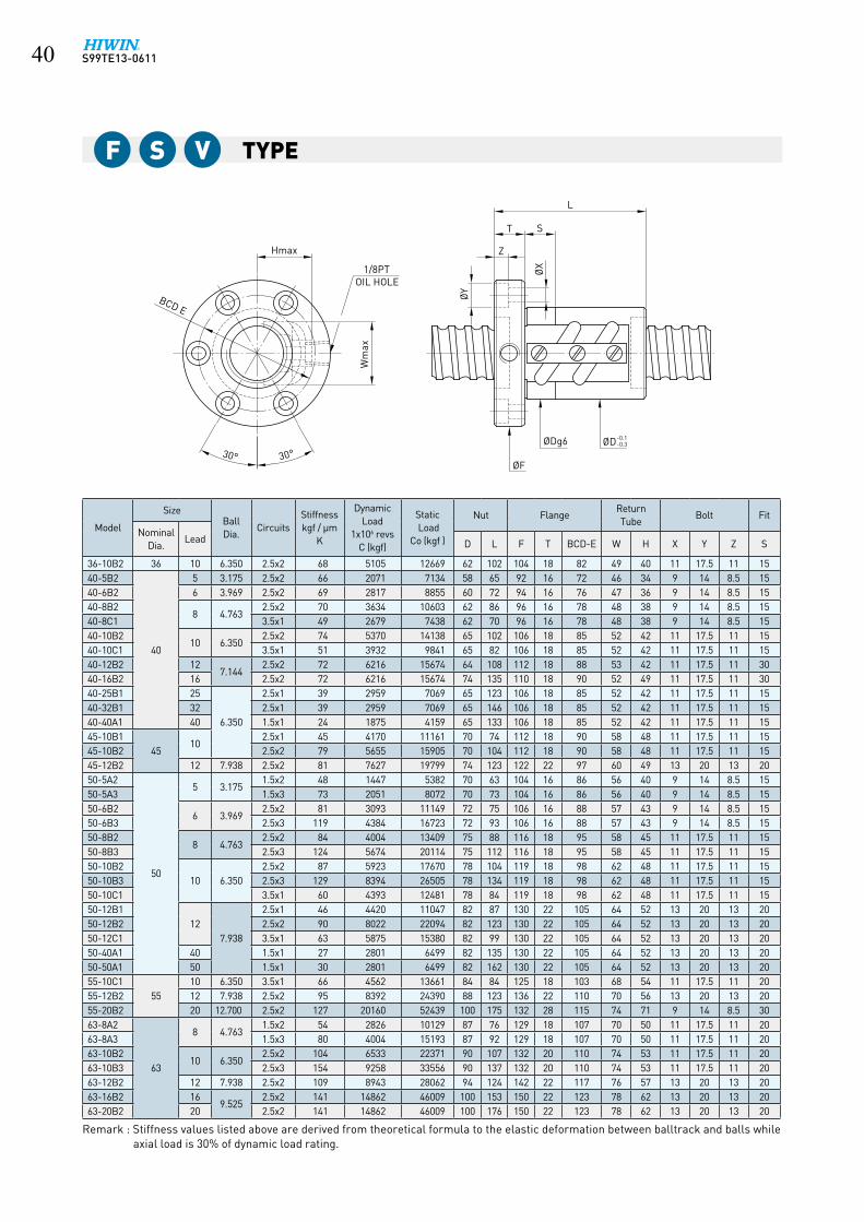
6.2 Dimension for Precision Ground Ballscrew
OIL HOLE
ØF
ØD-0.1-0.3ØDg6
30°30°
1/8PT
Wm
ax
Hmax
BCD E
ØX
ØY
L
Z
ST
Remark : Stiffness values listed above are derived from theoretical formula to the elastic deformation between balltrack and balls while axial load is 30% of dynamic load rating.
S99TE13-0611�0
TypeF S V
OIL HOLE
ØF
ØD-0.1-0.3ØDg6
30°30°
1/8PT
Wm
ax
Hmax
BCD E
ØX
ØY
L
Z
ST
Model
SizeBallDia.
CircuitsStiffnesskgf / μm
K
DynamicLoad
1x10⁶ revsC (kgf)
Static Load
Co (kgf )
Nut FlangeReturnTube
Bolt Fit
NominalDia.
Lead D L F T BCD-E W H X Y Z S
36-10B2 36 10 6.350 2.5x2 68 5105 12669 62 102 104 18 82 49 40 11 17.5 11 1540-5B2
40
5 3.175 2.5x2 66 2071 7134 58 65 92 16 72 46 34 9 14 8.5 1540-6B2 6 3.969 2.5x2 69 2817 8855 60 72 94 16 76 47 36 9 14 8.5 1540-8B2
8 4.7632.5x2 70 3634 10603 62 86 96 16 78 48 38 9 14 8.5 15
40-8C1 3.5x1 49 2679 7438 62 70 96 16 78 48 38 9 14 8.5 1540-10B2
10 6.3502.5x2 74 5370 14138 65 102 106 18 85 52 42 11 17.5 11 15
40-10C1 3.5x1 51 3932 9841 65 82 106 18 85 52 42 11 17.5 11 1540-12B2 12
7.1442.5x2 72 6216 15674 64 108 112 18 88 53 42 11 17.5 11 30
40-16B2 16 2.5x2 72 6216 15674 74 135 110 18 90 52 49 11 17.5 11 3040-25B1 25
6.350
2.5x1 39 2959 7069 65 123 106 18 85 52 42 11 17.5 11 1540-32B1 32 2.5x1 39 2959 7069 65 146 106 18 85 52 42 11 17.5 11 1540-40A1 40 1.5x1 24 1875 4159 65 133 106 18 85 52 42 11 17.5 11 1545-10B1
4510
2.5x1 45 4170 11161 70 74 112 18 90 58 48 11 17.5 11 1545-10B2 2.5x2 79 5655 15905 70 104 112 18 90 58 48 11 17.5 11 1545-12B2 12 7.938 2.5x2 81 7627 19799 74 123 122 22 97 60 49 13 20 13 2050-5A2
50
5 3.1751.5x2 48 1447 5382 70 63 104 16 86 56 40 9 14 8.5 15
50-5A3 1.5x3 73 2051 8072 70 73 104 16 86 56 40 9 14 8.5 1550-6B2
6 3.9692.5x2 81 3093 11149 72 75 106 16 88 57 43 9 14 8.5 15
50-6B3 2.5x3 119 4384 16723 72 93 106 16 88 57 43 9 14 8.5 1550-8B2
8 4.7632.5x2 84 4004 13409 75 88 116 18 95 58 45 11 17.5 11 15
50-8B3 2.5x3 124 5674 20114 75 112 116 18 95 58 45 11 17.5 11 1550-10B2
10 6.3502.5x2 87 5923 17670 78 104 119 18 98 62 48 11 17.5 11 15
50-10B3 2.5x3 129 8394 26505 78 134 119 18 98 62 48 11 17.5 11 1550-10C1 3.5x1 60 4393 12481 78 84 119 18 98 62 48 11 17.5 11 1550-12B1
127.938
2.5x1 46 4420 11047 82 87 130 22 105 64 52 13 20 13 2050-12B2 2.5x2 90 8022 22094 82 123 130 22 105 64 52 13 20 13 2050-12C1 3.5x1 63 5875 15380 82 99 130 22 105 64 52 13 20 13 2050-40A1 40 1.5x1 27 2801 6499 82 135 130 22 105 64 52 13 20 13 2050-50A1 50 1.5x1 30 2801 6499 82 162 130 22 105 64 52 13 20 13 2055-10C1
5510 6.350 3.5x1 66 4562 13661 84 84 125 18 103 68 54 11 17.5 11 20
55-12B2 12 7.938 2.5x2 95 8392 24390 88 123 136 22 110 70 56 13 20 13 2055-20B2 20 12.700 2.5x2 127 20160 52439 100 175 132 28 115 74 71 9 14 8.5 3063-8A2
63
8 4.7631.5x2 54 2826 10129 87 76 129 18 107 70 50 11 17.5 11 20
63-8A3 1.5x3 80 4004 15193 87 92 129 18 107 70 50 11 17.5 11 2063-10B2
10 6.3502.5x2 104 6533 22371 90 107 132 20 110 74 53 11 17.5 11 20
63-10B3 2.5x3 154 9258 33556 90 137 132 20 110 74 53 11 17.5 11 2063-12B2 12 7.938 2.5x2 109 8943 28062 94 124 142 22 117 76 57 13 20 13 2063-16B2 16
9.5252.5x2 141 14862 46009 100 153 150 22 123 78 62 13 20 13 20
63-20B2 20 2.5x2 141 14862 46009 100 176 150 22 123 78 62 13 20 13 20
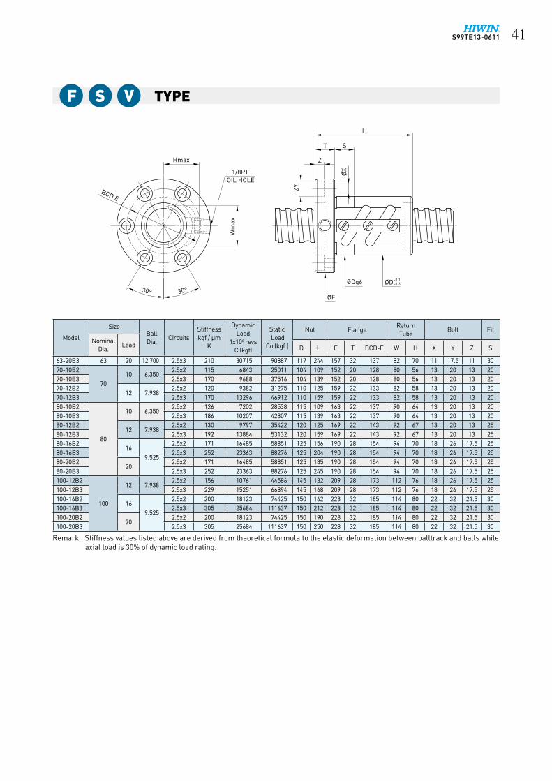
Remark : Stiffness values listed above are derived from theoretical formula to the elastic deformation between balltrack and balls while axial load is 30% of dynamic load rating.
S99TE13-0611 ��
TypeF S V
OIL HOLE
ØF
ØD-0.1-0.3ØDg6
30°30°
1/8PT
Wm
ax
Hmax
BCD E
ØX
ØY
L
Z
ST
Model
SizeBallDia.
CircuitsStiffnesskgf / μm
K
DynamicLoad
1x10⁶ revsC (kgf)
Static Load
Co (kgf )
Nut FlangeReturnTube
Bolt Fit
NominalDia.
Lead D L F T BCD-E W H X Y Z S
63-20B3 63 20 12.700 2.5x3 210 30715 90887 117 244 157 32 137 82 70 11 17.5 11 3070-10B2
7010 6.350
2.5x2 115 6843 25011 104 109 152 20 128 80 56 13 20 13 2070-10B3 2.5x3 170 9688 37516 104 139 152 20 128 80 56 13 20 13 2070-12B2
12 7.9382.5x2 120 9382 31275 110 125 159 22 133 82 58 13 20 13 20
70-12B3 2.5x3 170 13296 46912 110 159 159 22 133 82 58 13 20 13 2080-10B2
80
10 6.3502.5x2 126 7202 28538 115 109 163 22 137 90 64 13 20 13 20
80-10B3 2.5x3 186 10207 42807 115 139 163 22 137 90 64 13 20 13 2080-12B2
12 7.9382.5x2 130 9797 35422 120 125 169 22 143 92 67 13 20 13 25
80-12B3 2.5x3 192 13884 53132 120 159 169 22 143 92 67 13 20 13 2580-16B2
169.525
2.5x2 171 16485 58851 125 156 190 28 154 94 70 18 26 17.5 2580-16B3 2.5x3 252 23363 88276 125 204 190 28 154 94 70 18 26 17.5 2580-20B2
202.5x2 171 16485 58851 125 185 190 28 154 94 70 18 26 17.5 25
80-20B3 2.5x3 252 23363 88276 125 245 190 28 154 94 70 18 26 17.5 25100-12B2
100
12 7.9382.5x2 156 10761 44586 145 132 209 28 173 112 76 18 26 17.5 25
100-12B3 2.5x3 229 15251 66894 145 168 209 28 173 112 76 18 26 17.5 25100-16B2
169.525
2.5x2 200 18123 74425 150 162 228 32 185 114 80 22 32 21.5 30100-16B3 2.5x3 305 25684 111637 150 212 228 32 185 114 80 22 32 21.5 30100-20B2
202.5x2 200 18123 74425 150 190 228 32 185 114 80 22 32 21.5 30
100-20B3 2.5x3 305 25684 111637 150 250 228 32 185 114 80 22 32 21.5 30
Remark : Stiffness values listed above are derived from theoretical formula to the elastic deformation between balltrack and balls while axial load is 30% of dynamic load rating.

S99TE13-0611��
Type
Model
SizeBallDia.
CircuitsStiffnesskgf / μm
K
DynamicLoad
1x10⁶ revsC (kgf)
StaticLoad
Co (kgf )
Nut Flange Bolt Fit
NominalDia.
Lead D L F T BCD-E X Y Z S
12-4B112
42.381
2.5x1 8 383 638 30 38 50 10 40 4.5 8 4 1212-4C1 3.5x1 9 511 893 30 44 50 10 40 4.5 8 4 1212-5B1
52.5x1 8 383 638 30 40 50 10 40 4.5 8 4 12
14-5B1 143.175
2.5x1 10 710 1216 34 40 57 11 45 5.5 9.5 5.5 1215-10A1
1510 1.5x1 9 474 781 34 48 57 11 45 5.5 9.5 5.5 12
15-20A1 20 1.5x1 9 474 781 34 62 58 12 45 5.5 9.5 9.5 1216-4B1
16
4 2.381 2.5x1 14 439 870 34 38 57 11 45 5.5 9.5 5.5 1216-5B1
5 3.175
2.5x1 16 763 1400 40 45 64 12 51 5.5 9.5 5.5 1216-5B2 2.5x2 33 1385 2799 40 60 64 12 51 5.5 9.5 5.5 1216-5C1 3.5x1 22 1013 1946 40 50 64 12 51 5.5 9.5 5.5 1220-5B1
20
2.5x1 19 837 1733 44 45 68 12 55 5.5 9.5 5.5 1220-5B2 2.5x2 39 1519 3465 44 60 68 12 55 5.5 9.5 5.5 1220-6B1
6 3.9692.5x1 20 1137 2187 48 48 72 12 59 5.5 9.5 5.5 12
20-6C1 3.5x1 28 1512 3041 48 66 72 12 59 5.5 9.5 5.5 1225-4B2
25
4 2.381 2.5x2 38 976 2776 46 48 69 11 57 5.5 9.5 5.5 1225-5B2
5 3.1752.5x2 46 1704 4417 50 60 74 12 62 5.5 9.5 5.5 12
25-5C1 3.5x1 35 1252 3085 50 50 74 12 62 5.5 9.5 5.5 1225-6B1
6 3.9692.5x1 24 1255 2735 53 44 76 11 64 5.5 9.5 5.5 12
25-6B2 2.5x2 48 2308 5523 56 68 82 12 69 6.6 11 6.5 1225-6C1 3.5x1 35 1690 3844 56 55 82 12 69 6.6 11 6.5 1225-10B1
10 4.7632.5x1 25 1592 3237 60 65 86 16 73 6.6 11 6.5 12
25-10B2 2.5x2 46 2888 6472 58 97 85 15 71 6.6 11 6.5 1225-12B1 12 3.969 2.5x1 24 1271 2761 53 60 78 11 64 6.6 11 6.5 1228-5B1
28
53.175
2.5x1 26 984 2466 55 45 85 12 69 6.6 11 6.5 1228-5B2 2.5x2 50 1785 4932 55 60 85 12 69 6.6 11 6.5 1228-6A2 6 1.5x2 29 1150 2960 55 55 85 12 69 6.6 11 6.5 1228-12B2 12
4.7632.5x2 51 3060 7299 60 110 86 12 73 6.6 11 6.5 12
28-16B1 16 2.5x1 25 1686 3649 62 84 89 12 75 6.6 11 6.5 1232-5B2
32
5 3.1752.5x2 55 1886 5666 58 60 84 12 71 6.6 11 6.5 12
32-5C1 3.5x1 39 1388 3967 58 50 84 12 71 6.6 11 6.5 1232-6B2
6 3.9692.5x2 56 2556 7020 62 68 88 12 75 6.6 11 6.5 12
32-6C1 3.5x1 39 1888 4936 62 55 88 12 75 6.6 11 6.5 1232-8B2
8 4.7632.5x2 59 3284 8453 66 86 100 16 82 9 14 8.5 15
32-8C1 3.5x1 41 2428 5948 66 70 100 16 82 9 14 8.5 1532-10B2
106.350
2.5x2 60 4810 11199 74 98 108 16 90 9 14 8.5 1532-10C1 3.5x1 44 3519 7785 74 78 108 16 90 9 14 8.5 1532-12A2
121.5x2 37 3051 6612 74 97 108 18 90 9 14 8.5 15
32-12B2 2.5x2 59 4810 11199 74 110 108 18 90 9 14 8.5 15
ØDg6 ØD -0.1-0.3ØF
ØX
T<12 M6×1P
OIL HOLET≥12 1/8PT
BCD E
30°
30°
S
ØY
Z
T
L
Remark : Stiffness values listed above are derived from theoretical formula to the elastic deformation between balltrack and balls while axial load is 30% of dynamic load rating.
F S W

S99TE13-0611 ��
Type
ØDg6 ØD -0.1-0.3ØF
ØX
T<12 M6×1P
OIL HOLET≥12 1/8PT
BCD E
30°
30°
S
ØY
Z
T
L
F S W
Model
SizeBallDia.
CircuitsStiffnesskgf / μm
K
DynamicLoad
1x10⁶ revsC (kgf)
StaticLoad
Co (kgf )
Nut Flange Bolt Fit
NominalDia.
Lead D L F T BCD-E X Y Z S
32-16A2
3216
6.350
1.5x2 36 3035 6555 74 99 108 16 90 9 14 8.5 1532-16B1 2.5x1 30 2650 5599 74 94 108 16 90 9 14 8.5 1532-16B2 2.5x2 59 4810 11199 74 130 108 16 90 9 14 8.5 1532-20A2
201.5x2 37 3035 6555 74 120 108 16 90 9 14 8.5 15
32-20B1 2.5x1 30 2650 5599 74 98 108 16 90 9 14 8.5 1536-6B1
36
6 3.9692.5x1 35 1486 3969 65 50 100 12 82 6.6 11 6.5 12
36-6B2 2.5x2 60 2696 7937 65 68 100 12 82 6.6 11 6.5 1236-10B2 10
6.3502.5x2 68 5105 12669 75 102 125 18 98 11 17.5 11 15
36-12B2 12 2.5x2 65 5105 12668 75 110 125 18 98 11 17.5 11 1536-16C1 16 3.5x1 46 3736 8813 80 105 120 18 100 11 17.5 11 1540-5B2
40
5 3.175 2.5x2 66 2071 7134 68 65 102 16 84 9 14 8.5 1540-6B2 6 3.969 2.5x2 69 2817 8855 70 72 104 16 86 9 14 8.5 1540-8B2
8 4.7632.5x2 70 3634 10603 74 86 108 16 90 9 14 8.5 15
40-8C1 3.5x1 49 2679 7438 74 70 108 16 90 9 14 8.5 1540-10B2
10 6.3502.5x2 74 5370 14138 84 102 125 18 104 11 17.5 11 15
40-10C1 3.5x1 51 3932 9841 84 82 125 18 104 11 17.5 11 1540-12B1
127.144
2.5x1 36 3425 7837 86 81 128 18 106 11 17.5 11 2040-12B2 2.5x2 72 6217 15674 86 117 128 18 106 11 17.5 11 2040-16A2
161.5x2 42 4007 9405 86 118 128 18 106 11 17.5 11 20
40-16B1 2.5x1 37 3425 7837 86 102 128 18 106 11 17.5 11 2045-10B1
4510 6.350
2.5x1 45 3116 7953 88 74 132 18 110 11 17.5 11 1545-10B2 2.5x2 79 5655 15905 88 104 132 18 110 11 17.5 11 1545-12B2 12 7.938 2.5x2 81 7627 19799 96 123 142 22 117 13 20 13 2050-5A2
50
5 3.1751.5x2 48 1447 5382 80 63 114 16 96 9 14 8.5 15
50-5A3 1.5x3 73 2051 8072 80 73 114 16 96 9 14 8.5 1550-6B2
6 3.9692.5x2 81 3093 11149 84 75 118 16 100 9 14 8.5 15
50-6C2 3.5x2 109 4131 15608 84 80 118 15 100 9 14 8.5 1550-6B3 2.5x3 119 4384 16723 84 93 118 16 100 9 14 8.5 1550-8B2
8 4.7632.5x2 84 4004 13409 87 88 128 18 107 11 17.5 11 15
50-8B3 2.5x3 124 5674 20114 87 112 128 18 107 11 17.5 11 1550-10B2
10 6.3502.5x2 87 5923 17670 94 104 135 18 114 11 17.5 11 15
50-10B3 2.5x3 129 8394 26505 94 134 135 18 114 11 17.5 11 1550-10C1 3.5x1 60 4393 12481 94 84 135 18 114 11 17.5 11 1550-12B1
12 7.9382.5x1 46 4420 11047 102 87 150 22 125 13 20 13 20
50-12B2 2.5x2 90 8022 22094 102 123 150 22 125 13 20 13 2050-12C1 3.5x1 63 5875 15380 102 99 150 22 125 13 20 13 2050-30A2 30 6.350 1.5x2 52 3834 10658 94 160 135 18 140 11 17.5 11 15
Remark : Stiffness values listed above are derived from theoretical formula to the elastic deformation between balltrack and balls while axial load is 30% of dynamic load rating.

S99TE13-0611��
Type
ØDg6 ØD -0.1-0.3ØF
ØX
T<12 M6×1P
OIL HOLET≥12 1/8PT
BCD E
30°
30°
S
ØY
Z
T
L
F S W
Model
SizeBallDia.
CircuitsStiffnesskgf / μm
K
DynamicLoad
1x10⁶ revsC (kgf)
StaticLoad
Co (kgf )
Nut Flange Bolt Fit
NominalDia.
Lead D L F T BCD-E X Y Z S
55-10B255
10 6.3502.5x2 93 6071 19592 102 103 144 18 122 11 17.5 11 20
55-10C1 3.5x1 66 4562 13661 100 84 140 18 118 11 17.5 11 2055-12B2
12 7.9382.5x2 95 8392 24390 105 123 154 22 127 13 20 13 20
60-12B2 60 2.5x2 101 8742 26685 112 135 154 18 132 11 17.5 11 2063-8A2
63
8 4.7631.5x2 54 2826 10129 104 76 146 18 124 11 17.5 11 20
63-8A3 1.5x3 80 4004 15193 104 92 146 18 124 11 17.5 11 2063-10B2
10 6.3502.5x2 104 6533 22371 110 107 152 20 130 11 17.5 11 20
63-10B3 2.5x3 154 9528 33556 110 137 152 20 130 11 17.5 11 2063-12B2 12 7.938 2.5x2 109 8943 28062 118 124 166 22 141 13 20 13 2063-16B2 16
9.5252.5x2 141 14862 46009 124 153 172 22 147 13 20 13 20
63-20B2 20 2.5x2 141 14862 46009 124 176 172 22 147 13 20 13 2070-10B2
7010 6.350
2.5x2 115 6843 25011 124 109 170 20 145 13 20 13 2070-10B3 2.5x3 170 9698 37516 124 139 170 20 145 13 20 13 2070-12B2
12 7.9382.5x2 120 9382 31275 130 125 178 22 152 13 20 13 20
70-12B3 2.5x3 170 13296 46912 130 159 178 22 152 13 20 13 2080-10B2
80
10 6.3502.5x2 126 7202 28538 130 109 178 22 152 13 20 13 20
80-10B3 2.5x3 186 10207 42807 130 139 178 22 152 13 20 13 2080-12B2
12 7.9382.5x2 130 9797 35422 136 125 185 22 159 13 20 13 20
80-12B3 2.5x3 192 13844 53132 136 159 185 22 159 13 20 13 2080-16B2
169.525
2.5x2 171 16485 58851 145 156 210 28 154 18 26 17.5 2580-16B3 2.5x3 252 23363 88276 145 204 210 28 154 18 26 17.5 2580-20B2
202.5x2 171 16485 58851 145 185 210 28 154 18 26 17.5 25
80-20B3 2.5x3 252 23363 88276 145 245 210 28 154 18 26 17.5 25100-12B2
100
12 7.9382.5x2 156 10761 44596 160 132 224 24 188 18 26 17.5 25
100-12B3 2.5x3 229 15251 66894 160 168 224 24 188 18 26 17.5 25100-16B2
169.525
2.5x2 200 18123 77425 170 162 248 32 205 22 32 21.5 30100-16B3 2.5x3 305 25684 111637 170 212 248 32 205 22 32 21.5 30100-20B2
202.5x2 200 18123 74425 170 190 248 32 205 22 32 21.5 30
100-20B3 2.5x3 305 25684 111637 170 250 248 32 205 22 32 21.5 30
Remark : Stiffness values listed above are derived from theoretical formula to the elastic deformation between balltrack and balls while axial load is 30% of dynamic load rating.

S99TE13-0611 ��
TypeF D V
ModelSize
BallDia.
CircuitsStiffnesskgf / μm
K
DynamicLoad
1x10⁶ revsC (kgf)
Static Load
Co (kgf )
Nut FlangeReturnTube
Bolt Fit
NominalDia.
Lead D L F T BCD-E W H X Y Z S
16-5B116
5 3.175
2.5x1 32 763 1400 31 80 54 12 41 24 22 5.5 9.5 5.5 2416-5B2 2.5x2 65 1385 2799 31 110 54 12 41 24 22 5.5 9.5 5.5 2416-5C1 3.5x1 46 1013 1946 31 90 54 12 41 24 22 5.5 9.5 5.5 2420-5B1
20
2.5x1 38 837 1733 35 80 58 12 46 27 25 5.5 9.5 5.5 2420-5B2 2.5x2 76 1519 3465 35 110 58 12 46 27 25 5.5 9.5 5.5 2420-6B1
6 3.9692.5x1 40 1139 2187 36 92 60 12 47 28 27 5.5 9.5 5.5 24
20-6C1 3.5x1 55 1512 3041 36 104 60 12 47 28 27 5.5 9.5 5.5 2425-5B1
25
5 3.1752.5x1 46 939 2209 40 80 64 12 52 31 26 5.5 9.5 5.5 24
25-5B2 2.5x2 90 1704 4417 40 110 64 12 52 31 26 5.5 9.5 5.5 2425-5C1 3.5x1 68 1252 3085 40 90 64 12 52 31 26 5.5 9.5 5.5 2425-6B2
6 3.9692.5x2 94 2308 5523 42 128 68 12 55 32 28 6.6 11 6.5 24
25-6C1 3.5x1 66 1690 3844 42 104 68 12 55 32 28 6.6 11 6.5 2425-10B1 10 4.763 2.5x1 48 1592 3237 45 122 72 16 58 34 29 6.6 11 6.5 2428-5B1
28
53.175
2.5x1 51 984 2466 44 80 70 12 56 34 28 6.6 11 6.5 2428-5B2 2.5x2 98 1785 4932 44 110 70 12 56 34 28 6.6 11 6.5 2428-6A2 6 1.5x2 59 1150 2960 44 110 70 12 56 34 28 6.6 11 6.5 2428-8A2 8
4.7631.5x2 62 1960 4348 50 110 75 12 61 38 32 6.6 11 6.5 15
28-10B2 10 2.5x2 102 3060 7299 54 177 94 15 74 37 32 9 14 8.5 3032-5B1
32
5 3.1752.5x1 55 1039 2833 50 80 76 12 63 38 30 6.6 11 6.5 24
32-5B2 2.5x2 109 1886 5666 50 110 76 12 63 38 30 6.6 11 6.5 2432-5C1 3.5x1 76 1388 3967 50 90 76 12 63 38 30 6.6 11 6.5 2432-6B1
6 3.9692.5x1 57 1409 3510 52 92 78 12 65 39 32 6.6 11 6.5 24
32-6B2 2.5x2 112 2556 7020 52 128 78 12 65 39 32 6.6 11 6.5 2432-6C1 3.5x1 78 1888 4936 52 104 78 12 65 39 32 6.6 11 6.5 2432-8B1
8 4.7632.5x1 58 1810 4227 54 110 88 16 70 40 33 9 14 8.5 30
32-8B2 2.5x2 115 3284 8453 54 158 88 16 70 40 33 9 14 8.5 3032-8C1 3.5x1 82 2428 5948 54 126 88 16 70 40 33 9 14 8.5 3032-10B1
10
6.350
2.5x1 58 2651 5600 57 122 91 16 73 44 37 9 14 8.5 3032-10B2 2.5x2 118 4810 11199 57 182 91 16 73 44 37 9 14 8.5 3032-10C1 3.5x1 86 3519 7785 57 142 91 16 73 44 37 9 14 8.5 3032-12A2
121.5x2 72 3035 6555 62 180 108 16 86 44 38 9 14 8.5 15
32-12B1 2.5x1 62 2650 5599 62 138 108 16 86 44 38 9 14 8.5 2032-16A2 16 1.5x2 72 3035 6555 62 180 108 16 86 44 38 9 14 8.5 2036-6B1
366 3.969
2.5x1 62 1486 3969 55 92 82 12 68 42 32 6.6 11 6.5 2436-6B2 2.5x2 121 2696 7937 55 128 82 12 68 42 32 6.6 11 6.5 2436-10B2 10 6.350 2.5x2 132 5105 12669 62 184 104 18 82 49 40 11 17.5 11 30
OIL HOLE
ØD-0.1-0.3ØDg6
ØF
ØX
ØY
L±1.5
S
Z
T
1/8PT
Wm
ax
Hmax
BCD E
30°30°ØD-0.1
-0.3
Remark : Stiffness values listed above are derived from theoretical formula to the elastic deformation between balltrack and balls while preload is 10% of dynamic load rating and axial load is applied.

S99TE13-0611��
TypeF D V
OIL HOLE
ØD-0.1-0.3ØDg6
ØF
ØX
ØY
L±1.5
S
Z
T
1/8PT
Wm
ax
Hmax
BCD E
30°30°ØD-0.1
-0.3
ModelSize
BallDia.
CircuitsStiffnesskgf / μm
K
DynamicLoad
1x10⁶ revsC (kgf)
Static Load
Co (kgf )
Nut FlangeReturnTube
Bolt Fit
NominalDia.
Lead D L F T BCD-E W H X Y Z S
40-5B1
40
5 3.1752.5x1 65 1141 3567 58 84 92 16 72 46 34 9 14 8.5 30
40-5B2 2.5x2 132 2071 7134 58 114 92 16 72 46 34 9 14 8.5 3040-6B2 6 3.969 2.5x2 136 2817 8855 60 132 94 16 76 47 36 9 14 8.5 3040-8B1
8 4.7632.5x1 69 2003 5302 62 110 96 16 78 48 38 9 14 8.5 30
40-8B2 2.5x2 137 3634 10603 62 158 96 16 78 48 38 9 14 8.5 3040-8C1 3.5x1 96 2679 7438 62 126 96 16 78 48 38 9 14 8.5 3040-10B1
10 6.3502.5x1 72 2959 7069 65 132 106 18 85 52 42 11 17.5 11 30
40-10B2 2.5x2 145 5370 14138 65 192 106 18 85 52 42 11 17.5 11 3040-10C1 3.5x1 102 3932 9841 65 152 106 18 85 52 42 11 17.5 11 3040-12A2 12 6.350 1.5x2 88 3402 8316 65 160 106 18 84 52 42 11 17.5 11 2040-12B1
12
7.144
2.5x1 70 3425 7837 70 153 112 18 90 55 43 11 17.5 11 4040-12B2 2.5x2 141 6217 15674 70 225 112 18 90 55 43 11 17.5 11 4040-12C1 12 3.5x1 103 3932 9841 65 158 106 18 85 52 42 11 17.5 11 3040-16A2 16 1.5x2 88 4006 9404 75 209 117 18 95 53 43 11 17.5 11 4040-16B1 16 2.5x1 118 3425 7837 75 153 117 18 95 53 43 11 17.5 11 4040-20A1 20
6.3501.5x1 44 1874 4158 65 152 106 18 85 52 42 11 17.5 11 30
45-10B145
102.5x1 76 3116 7953 70 134 112 18 90 58 48 11 17.5 11 30
45-10B2 2.5x2 156 5655 15905 70 194 112 18 90 58 48 11 17.5 11 3045-12B2 12 7.938 2.5x2 162 7627 19799 74 230 122 22 97 60 49 13 20 13 4050-5A2
50
53.175
1.5x2 96 1447 5382 70 107 104 16 86 56 40 9 14 8.5 3050-5A3 1.5x3 143 2051 8072 70 127 104 16 86 56 40 9 14 8.5 3050-5B2 5 2.5x2 153 2245 8969 70 116 104 16 86 56 40 9 14 8.5 3050-6B2
6 3.9692.5x2 161 3093 11149 72 134 106 16 88 57 43 9 14 8.5 30
50-6B3 2.5x3 235 4384 16723 72 170 106 16 88 57 43 9 14 8.5 3050-8B1
8 4.7632.5x1 81 2206 6705 75 112 116 18 95 58 45 11 17.5 11 30
50-8B2 2.5x2 165 4004 13409 75 160 116 18 95 58 45 11 17.5 11 3050-8B3 2.5x3 244 5674 20114 75 208 116 18 95 58 45 11 17.5 11 3050-10B2
10 6.3502.5x2 173 5923 17670 78 194 119 18 98 62 48 11 17.5 11 30
50-10B3 2.5x3 255 8394 26505 78 254 119 18 98 62 48 11 17.5 11 3050-10C1 3.5x1 120 4393 12481 78 154 119 18 98 62 48 11 17.5 11 3050-12B2
12 7.9382.5x2 178 8022 22094 82 232 130 22 105 64 52 13 20 13 40
50-12C1 3.5x1 123 5875 15380 82 184 130 22 105 64 52 13 20 13 4055-10C1
5510 6.350 3.5x1 132 4562 13661 84 154 125 18 103 68 54 11 17.5 11 40
55-12B2 12 7.938 2.5x2 185 8392 24390 88 232 136 22 110 70 56 13 20 13 40
Remark : Stiffness values listed above are derived from theoretical formula to the elastic deformation between balltrack and balls while preload is 10% of dynamic load rating and axial load is applied.

S99TE13-0611 ��
TypeF D V
OIL HOLE
ØD-0.1-0.3ØDg6
ØF
ØX
ØY
L±1.5
S
Z
T
1/8PT
Wm
ax
Hmax
BCD E
30°30°ØD-0.1
-0.3
ModelSize
BallDia.
CircuitsStiffnesskgf / μm
K
DynamicLoad
1x10⁶ revsC (kgf)
Static Load
Co (kgf )
Nut FlangeReturnTube
Bolt Fit
NominalDia.
Lead D L F T BCD-E W H X Y Z S
63-8A2
63
8 4.7631.5x2 107 2826 10129 87 142 129 18 107 70 50 11 17.5 11 40
63-8A3 1.5x3 154 4004 15193 87 171 129 18 107 70 50 11 17.5 11 4063-10B2
10 6.3502.5x2 206 6533 22371 90 196 132 20 110 74 53 11 17.5 11 30
63-10B3 2.5x3 305 9258 33556 90 256 132 20 110 74 53 11 17.5 11 3063-12B2 12 7.938 2.5x2 214 8943 28062 94 232 142 22 117 76 57 13 20 13 4063-16B2 16
9.5252.5x2 280 14862 46009 100 296 150 22 123 78 62 13 20 13 40
63-20B2 20 2.5x2 280 14862 46009 100 334 150 22 123 78 62 13 20 13 4070-10B2
7010 6.350
2.5x2 228 6843 25011 104 196 152 20 128 80 56 13 20 13 4070-10B3 2.5x3 334 9698 37516 104 256 152 20 128 80 56 13 20 13 4070-12B2
12 7.9382.5x2 236 9382 31275 110 232 159 22 133 82 58 13 20 13 40
70-12B3 2.5x3 336 13296 46912 110 302 159 22 133 82 58 13 20 13 4080-10B2
80
10 6.3502.5x2 251 7202 28538 115 200 163 22 137 90 64 13 20 13 40
80-10B3 2.5x3 368 10207 42807 115 260 163 22 137 90 64 13 20 13 4080-12B2
12 7.9382.5x2 257 9797 35422 120 232 169 22 143 92 67 13 20 13 40
80-12B3 2.5x3 380 13884 53132 120 302 169 22 143 92 67 13 20 13 4080-16B2
169.525
2.5x2 340 16485 58851 125 302 190 28 154 94 70 18 26 17.5 5080-16B3 2.5x3 498 23363 88276 125 398 190 28 154 94 70 18 26 17.5 5080-20B2
202.5x2 338 16485 58851 125 345 190 28 154 94 70 18 26 17.5 50
80-20B3 2.5x3 498 23363 88276 125 470 190 28 154 94 70 18 26 17.5 50100-12B2
100
12 7.9382.5x2 301 10761 44596 145 240 209 28 173 112 76 18 26 17.5 50
100-12B3 2.5x3 452 15251 66894 145 312 209 28 173 112 76 18 26 17.5 50100-16B2
169.525
2.5x2 400 18125 74425 150 308 228 32 185 114 80 22 32 21.5 60100-16B3 2.5x3 595 25684 111637 150 404 228 32 185 114 80 22 32 21.5 60100-20B2
202.5x2 400 18123 74425 150 350 228 32 185 114 80 22 32 21.5 60
100-20B3 2.5x3 595 25684 111637 150 475 228 32 185 114 80 22 32 21.5 60
Remark : Stiffness values listed above are derived from theoretical formula to the elastic deformation between balltrack and balls while preload is 10% of dynamic load rating and axial load is applied.

S99TE13-0611��
TypeF D W
Model
SizeBallDia.
CircuitsStiffnesskgf / μm
K
DynamicLoad
1x10⁶ revsC (kgf)
Static Load
Co (kgf )
Nut Flange Bolt Fit
NominalDia.
Lead D L F T BCD-E X Y Z S
16-5B216
5 3.175
2.5x2 65 1385 2799 40 110 64 12 51 5.5 9.5 5.5 2416-5B1 2.5x1 32 763 1400 40 80 64 12 51 5.5 9.5 5.5 2416-5C1 3.5x1 46 1013 1946 40 90 64 12 51 5.5 9.5 5.5 2420-5B1
20
2.5x1 38 837 1733 44 80 68 12 55 5.5 9.5 5.5 2420-5B2 2.5x2 76 1519 3465 44 110 68 12 55 5.5 9.5 5.5 2420-6B1
6 3.9692.5x1 40 1139 2187 48 92 72 12 59 5.5 9.5 5.5 24
20-6C1 3.5x1 55 1512 3041 48 104 72 12 59 5.5 9.5 5.5 2425-5A2
25
5 3.175
1.5x2 54 1092 2622 50 102 73 11 61 5.5 9.5 5.5 2425-5B1 2.5x1 46 939 2209 50 80 74 12 62 5.5 9.5 5.5 2425-5B2 2.5x2 90 1704 4417 50 110 74 12 62 5.5 9.5 5.5 2425-5C1 3.5x1 68 1252 3085 50 90 74 12 62 5.5 9.5 5.5 2425-6B2
6 3.9692.5x2 94 2304 5524 56 128 82 12 69 6.6 11 6.5 24
25-6C1 3.5x1 66 1690 3844 56 104 82 12 69 6.6 11 6.5 2425-10B1 10 4.763 2.5x1 48 1592 3237 60 122 86 16 73 6.6 11 6.5 2428-5B1
285
3.175
2.5x1 51 984 2466 55 80 85 12 69 6.6 11 6.5 2428-5B2 2.5x2 98 1785 4932 55 110 85 12 69 6.6 11 6.5 2428-6A2
61.5x2 59 1150 2960 55 110 85 12 69 6.6 11 6.5 24
28-6B2 2.5x2 98 1776 4980 55 123 85 12 69 6.6 11 6.5 2432-4B2
32
4 2.381 2.5x2 91 1071 3582 54 93 81 12 67 6.6 11 6.5 2432-5B1
5 3.1752.5x1 55 1039 2833 58 80 84 12 71 6.6 11 6.5 24
32-5B2 2.5x2 109 1886 5666 58 110 84 12 71 6.6 11 6.5 2432-5C1 3.5x1 76 1388 3967 58 90 84 12 71 6.6 11 6.5 2432-6B1
6 3.9692.5x1 57 1409 3510 62 92 88 12 75 6.6 11 6.5 24
32-6B2 2.5x2 112 2556 7020 62 128 88 12 75 6.6 11 6.5 2432-6C1 3.5x1 78 1888 4936 62 104 88 12 75 6.6 11 6.5 2432-8A2
8 4.763
1.5x2 70 2082 5151 66 135 100 15 82 9 14 8.5 3032-8B1 2.5x1 58 1810 4227 66 110 100 16 82 9 14 8.5 3032-8B2 2.5x2 115 3284 8453 66 158 100 16 82 9 14 8.5 3032-8B3 2.5x3 168 4653 12678 74 205 108 16 90 9 14 8.5 3032-8C1 3.5x1 82 2428 5948 66 126 100 16 82 9 14 8.5 3032-10A2
10
6.350
1.5x2 72 3051 6612 74 167 108 15 90 9 14 8.5 3032-10B1 2.5x1 58 2651 5600 74 122 108 16 90 9 14 8.5 3032-10B2 2.5x2 118 4810 11199 74 182 108 16 90 9 14 8.5 3032-10C1 3.5x1 86 3519 7785 74 142 108 16 90 9 14 8.5 3032-12B1
122.5x1 62 2602 5510 74 153 108 18 90 9 14 8.5 30
32-12B2 2.5x2 118 4810 11199 74 232 108 16 90 9 14 8.5 3032-12C1 3.5x1 84 3518 7784 74 166 108 16 90 9 14 8.5 30
ØD -0.1-0.3ØD-0.1
-0.3ØDg6ØF
ØX
1/8PT
30°
30°
BCD E
Z
T
L ± 1.5
S
ØY
OIL HOLE
Remark : Stiffness values listed above are derived from theoretical formula to the elastic deformation between balltrack and balls while preload is 10% of dynamic load rating and axial load is applied.

S99TE13-0611 ��
TypeF D W
ØD -0.1-0.3ØD-0.1
-0.3ØDg6ØF
ØX
1/8PT
30°
30°
BCD E
Z
T
L ± 1.5
S
ØY
OIL HOLE
Model
SizeBallDia.
CircuitsStiffnesskgf / μm
K
DynamicLoad
1x10⁶ revsC (kgf)
Static Load
Co (kgf )
Nut Flange Bolt Fit
NominalDia.
Lead D L F T BCD-E X Y Z S
36-6B1
36
6 3.9692.5x1 62 1486 3969 65 92 100 12 82 6.6 11 6.5 24
36-6B2 2.5x2 121 2696 7937 65 128 100 12 82 6.6 11 6.5 2436-12A2
124.763 1.5x2 80 2557 6693 70 155 108 15 90 9 14 8.5 30
36-12B16.350
2.5x1 67 2812 6334 75 126 120 16 98 11 17.5 11 3036-10B2 10 2.5x2 132 5105 12669 75 184 120 18 98 11 17.5 11 3036-12B2 12 2.5x2 130 5105 12668 75 206 120 18 98 11 17.5 11 3036-8A2
8 4.7631.5x2 77 2217 5669 70 135 108 15 90 9 14 8.5 30
36-8B2 2.5x2 126 3489 9606 70 158 108 15 90 9 14 8.5 3040-5B1
40
5 3.1752.5x1 65 1141 3567 68 84 102 16 84 9 14 8.5 30
40-5B2 2.5x2 132 2071 7134 68 114 102 16 84 9 14 8.5 3040-6B2 6 3.969 2.5x2 136 2817 8855 70 132 104 16 86 9 14 8.5 3040-8B1
8 4.763
2.5x1 69 2003 5302 74 110 108 16 90 9 14 8.5 3040-8B2 2.5x2 137 3634 10603 74 158 108 16 90 9 14 8.5 3040-8B3 2.5x3 200 5150 15904 74 210 108 15 90 9 14 8.5 3040-8C1 3.5x1 96 2679 7438 74 126 108 16 90 9 14 8.5 3040-10A2
10 6.350
1.5x2 87 3418 8398 82 170 124 18 102 11 17.5 11 3040-10B1 2.5x1 72 2959 7069 84 132 125 18 104 11 17.5 11 3040-10B2 2.5x2 145 5370 14138 84 192 125 18 104 11 17.5 11 3040-10C1 3.5x1 102 3932 9841 84 152 125 18 104 11 17.5 11 3040-12A2
12
7.144
1.5x2 88 4006 9404 86 160 128 18 106 11 17.5 11 3040-12B1 2.5x1 70 3425 7837 86 153 128 18 106 11 17.5 11 4040-12B2 2.5x2 141 6217 15674 86 225 128 18 106 11 17.5 11 4040-12C1 3.5x1 103 4637 11146 86 179 128 18 106 11 17.5 11 3040-16A2
161.5x2 83 4007 9405 86 214 128 18 106 11 17.5 11 40
40-16B1 2.5x1 72 3425 7837 86 182 128 18 106 11 17.5 11 4040-16B2 2.5x2 143 6216 15674 86 272 128 22 106 11 17.5 11 3045-10B1
4510 6.350
2.5x1 76 3111 7953 88 134 132 18 110 11 17.5 11 3045-10B2 2.5x2 156 5655 15905 88 194 132 18 110 11 17.5 11 3045-12B2 12 7.938 2.5x2 162 7627 19799 96 230 142 22 117 13 20 13 4045-16B2 16 7.144 2.5x2 158 6636 17895 90 278 132 18 110 11 17.5 11 3050-5A2
50
5 3.1751.5x2 96 1447 5382 80 107 114 16 96 9 14 8.5 30
50-5A3 1.5x3 143 2051 8072 80 127 114 16 96 9 14 8.5 3050-6B2
6 3.9692.5x2 161 3093 11149 84 134 118 16 100 9 14 8.5 30
50-6B3 2.5x3 235 4384 16723 84 170 118 16 100 9 14 8.5 3050-8B1
8 4.7632.5x1 81 2206 6705 87 112 128 18 107 11 17.5 11 30
50-8B2 2.5x2 165 4004 13409 87 160 128 18 107 11 17.5 11 3050-8B3 2.5x3 244 5674 20114 87 208 128 18 107 11 17.5 11 3050-10B1 10 6.350 2.5x1 88 3245 8918 93 133 135 18 113 11 17.5 11 30
Remark : Stiffness values listed above are derived from theoretical formula to the elastic deformation between balltrack and balls while preload is 10% of dynamic load rating and axial load is applied.

S99TE13-0611�0
TypeF D W
ØD -0.1-0.3ØD-0.1
-0.3ØDg6ØF
ØX
1/8PT
30°
30°
BCD E
Z
T
L ± 1.5
S
ØY
OIL HOLE
Model
SizeBallDia.
CircuitsStiffnesskgf / μm
K
DynamicLoad
1x10⁶ revsC (kgf)
Static Load
Co (kgf )
Nut Flange Bolt Fit
NominalDia.
Lead D L F T BCD-E X Y Z S
50-10B2
50
10 6.3502.5x2 173 5923 17670 94 194 135 18 114 11 17.5 11 30
50-10B3 2.5x3 255 8394 26505 94 254 135 18 114 11 17.5 11 3050-10C1 3.5x1 120 4393 12481 94 154 135 18 114 11 17.5 11 3050-12B1
127.938
2.5x1 90 4367 10918 100 159 146 22 122 14 20 13 4050-12B2 2.5x2 178 8022 22094 102 232 150 22 125 13 20 13 4050-12C1 3.5x1 123 5875 15380 102 184 150 22 125 13 20 13 4050-16B2 16 2.5x2 174 7918 21837 100 280 146 22 122 14 20 13 4050-20B1 20 2.5x1 90 4367 10918 100 227 146 28 122 14 20 13 4055-10C1
5510 6.350 3.5x1 132 4562 13661 100 154 140 18 118 11 17.5 11 40
55-12B2 12 7.938 2.5x2 185 8392 24390 105 232 154 22 127 13 20 13 4063-8A2
63
8 4.7631.5x2 107 2826 10129 104 142 146 18 124 11 17.5 11 40
63-8A3 1.5x3 154 4004 15193 104 174 146 18 124 11 17.5 11 4063-10B2
10 6.3502.5x2 206 6533 22371 110 196 152 20 130 11 17.5 11 30
63-10B3 2.5x3 305 9258 33556 110 256 152 20 130 11 17.5 11 3063-12B2 12 7.938 2.5x2 214 8943 28062 118 232 166 22 141 13 20 13 4063-16B2 16
9.5252.5x2 280 14862 46009 124 296 172 22 147 13 20 13 40
63-20B2 20 2.5x2 280 14862 46009 124 334 172 22 147 13 20 13 4070-10B2
70
10 6.3502.5x2 228 6843 25011 124 196 170 20 145 13 20 13 40
70-10B3 2.5x3 334 9698 37516 124 256 170 20 145 13 20 13 4070-12B2
12 7.9382.5x2 236 9382 31275 130 232 178 22 152 13 20 13 40
70-12B3 2.5x3 336 13296 46912 130 302 178 22 152 13 20 13 4070-20B2 20 9.525 2.5x2 300 15644 51502 130 325 186 28 158 18 26 17.5 6080-10B2
80
10 6.3502.5x2 251 7202 28538 130 200 178 22 152 13 20 13 40
80-10B3 2.5x3 368 10207 42807 130 260 178 22 152 13 20 13 4080-12B2
12 7.9382.5x2 257 9797 35422 136 232 185 22 159 13 20 13 40
80-12B3 2.5x3 380 13884 53132 136 302 185 22 159 13 20 13 4080-16B2
169.525
2.5x2 340 16485 58851 145 302 210 28 174 18 26 17.5 5080-16B3 2.5x3 498 23363 88276 145 398 210 28 174 18 26 17.5 5080-20B2
202.5x2 338 16485 58851 145 345 210 28 174 18 26 17.5 50
80-20B3 2.5x3 498 23363 88276 145 470 210 28 174 18 26 17.5 50100-12B2
100
12 7.9382.5x2 301 10761 44596 160 240 224 28 188 18 26 17.5 50
100-12B3 2.5x3 452 15251 66894 160 312 224 28 188 18 26 17.5 50100-16B2
169.525
2.5x2 400 18123 74425 170 308 248 32 205 22 32 21.5 60100-16B3 2.5x3 595 25684 11637 170 404 248 32 205 22 32 21.5 60100-20B2
202.5x2 400 18123 74425 170 350 248 32 205 22 32 21.5 60
100-20B3 2.5x3 595 25684 11637 170 475 248 32 205 22 32 21.5 60
Remark : Stiffness values listed above are derived from theoretical formula to the elastic deformation between balltrack and balls while preload is 10% of dynamic load rating and axial load is applied.
S99TE13-0611 ��
TypeF S I
Model
SizeBallDia.
CircuitsStiffnesskgf / μm
K
DynamicLoad
1x10⁶ revsC (kgf)
StaticLoad
Co (kgf )
Nut Flange Bolt Fit
NominalDia.
Lead D L F T BCD-E X Y Z S
8-2.5T3 8 2.5 1.500 3 8 170 267 16 18 28 35 5 27 4.5 0 0 014-2.54T3
142.54
2.0003 12 339 655 28 30 39 50 10.6 40 5 7 5 0
14-4T3 4 3 12 339 655 24 26 33 48 6 36 5.5 9.5 5.5 016-2T3
16
21.500
3 14 252 593 25 27 36 44 10 35 5.5 9.5 5.5 016-2.5T4 2.5 4 19 358 862 25 27 44 44 10 35 5.5 9.5 5.5 1216-5T3
53.175
3 11 731 1331 28 30 46 54 12 41 5.5 9.5 5.5 1216-5T4 4 12 936 1775 28 30 52 54 12 41 5.5 9.5 5.5 1216-6T4 6 4 21 936 1775 30 32 58 54 12 42 5.5 9.5 5.5 1220-2T6
20
2 1.5006 32 518 1551 30 32 52 52 10 40 5.5 9.5 5.5 12
20-2T4 4 36 399 1112 30 32 40 52 10 40 5.5 9.5 5.5 1220-2.5T5 2.5
2.0005 28 637 1635 34 36 51 59 12 47 5.5 9.5 5.5 12
20-2.54T6 2.54 6 33 745 1962 34 36 55 59 12 47 5.5 9.5 5.5 1220-4T3 4 2.381 3 17 509 1134 34 36 40 59 10 47 5.5 9.5 5.5 1220-5T3
5 3.1753 20 852 1767 32 34 46 57 12 45 5.5 9.5 5.5 12
20-5T4 4 27 1091 2356 32 34 53 57 12 45 5.5 9.5 5.5 1220-6T3
63.969
3 20 1091 2081 34 36 51 60 12 48 5.5 9.5 5.5 1220-6T4 4 27 1398 2774 34 36 61 60 12 48 5.5 9.5 5.5 1220-10T3 10 3 20 1091 2080 33 35 64 57 12 45 5.5 9.5 5.5 1225-2T6
25
2 1.5006 39 560 1960 34 36 50 55 10 46 5.5 9.5 5.5 12
25-2T4 4 27 395 1307 34 36 40 55 10 46 5.5 9.5 5.5 1225-2T3 3 20 309 980 34 36 35 55 10 46 5.5 9.5 5.5 1225-2.5T5 2.5 2.000 5 34 716 2117 38 40 52 62 10 51 6.6 11 6.5 1225-4T4 4 2.381 4 28 747 1989 38 40 53 64 12 51 5.5 9.5 5.5 1225-5T3
53.175
3 28 977 2314 37 40 46 64 12 52 5.5 9.5 5.5 1225-5T4 4 37 1252 3085 37 40 53 64 12 52 5.5 9.5 5.5 1225-5T5 5 40 1516 3856 38 40 56 63 11 51 5.5 9.5 5.5 1225-5T6 6 48 1773 4627 38 40 65 63 11 51 5.5 9.5 5.5 1225-6T3
3.9693 28 1272 2762 38 42 51 65 12 53 5.5 9.5 5.5 12
25-6T4 4 37 1628 3682 38 42 61 65 12 53 5.5 9.5 5.5 1225-10T3
10 4.7633 25 1591 3236 42 45 80 69 15 55 6.6 11 6.5 12
25-10T4 4 33 2038 4315 42 45 85 69 15 55 6.6 11 6.5 12
ØX
ØD-0.1-0.3ØDg6
ØF
OIL HOLE1/8PT Ø
Y
L
Z
ST
30°
30°
BCD E
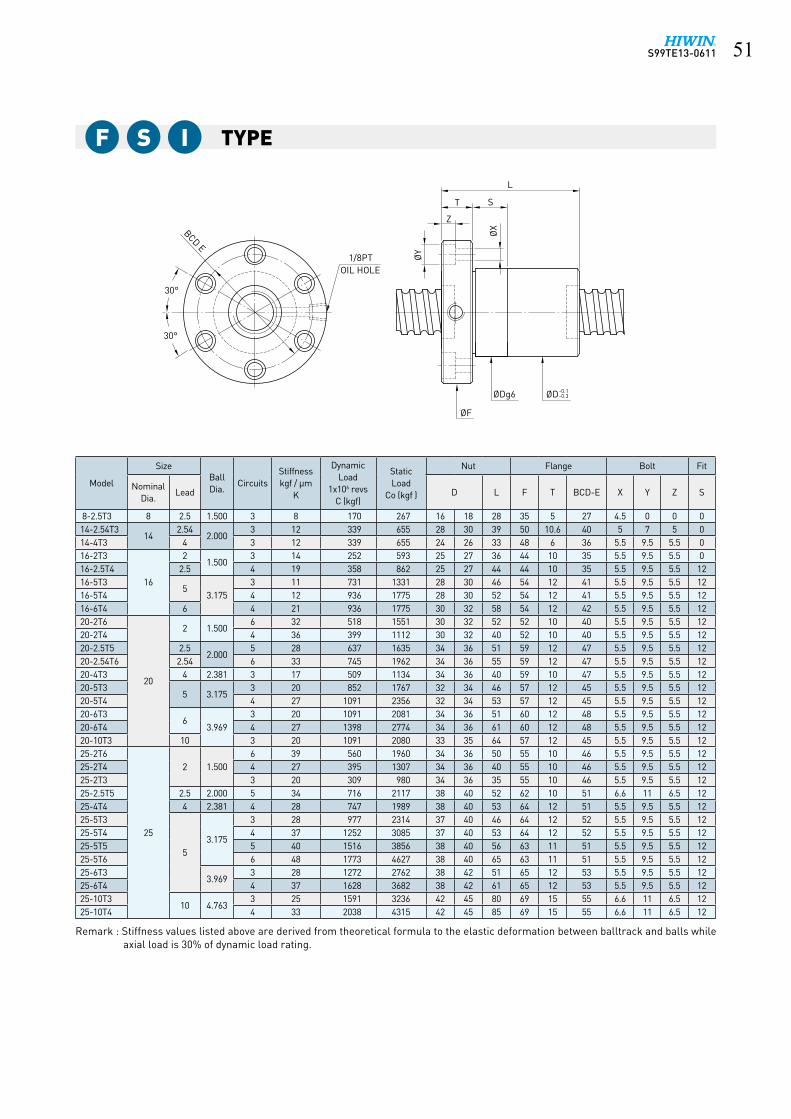
Remark : Stiffness values listed above are derived from theoretical formula to the elastic deformation between balltrack and balls while axial load is 30% of dynamic load rating.

S99TE13-0611��
TypeF S I
ØX
ØD-0.1-0.3ØDg6
ØF
OIL HOLE1/8PT Ø
Y
L
Z
ST
30°
30°
BCD E
Model
SizeBallDia.
CircuitsStiffnesskgf / μm
K
DynamicLoad
1x10⁶ revsC (kgf)
StaticLoad
Co (kgf )
Nut Flange Bolt Fit
NominalDia.
Lead D L F T BCD-E X Y Z S
32-5T3
32
5 3.1753 33 1117 3081 44 48 46 74 12 60 6.6 11 6.5 12
32-5T4 4 42 1431 4108 44 48 53 74 12 60 6.6 11 6.5 1232-5T6 6 63 2027 6162 44 48 66 74 12 60 6.6 11 6.5 1232-6T3
6 3.9693 33 1446 3620 45 50 51 76 12 62 6.6 11 6.5 12
32-6T4 4 43 1852 4826 45 50 61 76 12 62 6.6 11 6.5 1232-6T6 6 65 2625 7239 45 50 75 76 12 62 6.6 11 6.5 1232-8T3
8 4.7633 35 1810 4227 47 52 63 78 16 64 6.6 11 6.5 12
32-8T4 4 47 2317 5635 47 52 74 78 16 64 6.6 11 6.5 1232-10T3
10 6.3503 35 2539 5327 51 56 72 82 16 68 6.6 11 6.5 12
32-10T4 4 48 3252 7102 51 56 83 82 16 68 6.6 11 6.5 1240-5T4
40
5 3.1754 50 1599 5280 51 54 53 80 16 66 6.6 11 6.5 12
40-5T6 6 74 2265 7919 51 54 66 80 16 66 6.6 11 6.5 1240-5.08T6 5.08 3.175 6 74 2265 7919 53 56 65 90 15 72 9 14 8.5 1540-6T4
6 3.9694 50 2136 6420 53 56 65 88 16 72 9 14 8.5 15
40-6T6 6 74 3028 9630 53 56 79 88 16 72 9 14 8.5 1540-8T4
8 4.7634 52 2728 7596 55 60 78 92 16 75 9 14 8.5 15
40-8T6 6 76 3866 11394 55 60 99 92 16 75 9 14 8.5 1540-10T3
10 6.3503 40 2959 7069 60 65 76 96 16 80 9 14 8.5 15
40-10T4 4 51 3789 9426 60 65 87 96 16 80 9 14 8.5 1550-5T4
50
5 3.1754 62 1757 6745 62 65 57 96 16 80 9 14 8.5 15
50-5T6 6 91 2490 10117 62 65 70 96 16 80 9 14 8.5 1550-6T4
6 3.9694 62 2388 8250 64 68 65 100 16 84 9 14 8.5 15
50-6T6 6 93 3384 12375 64 68 79 100 16 84 9 14 8.5 1550-8T4
8 4.7634 62 2998 9578 65 70 78 102 16 85 9 14 8.5 15
50-8T6 6 92 4249 14367 65 70 99 102 16 85 9 14 8.5 1550-10T3
10 6.3503 50 3397 9256 69 74 78 114 18 92 11 17.5 11 20
50-10T4 4 63 4350 12341 69 74 89 114 18 92 11 17.5 11 2050-10T6 6 94 6165 18511 69 74 112 114 18 92 11 17.5 11 2050-12T3
12 7.9383 50 4420 11047 73 78 90 118 18 96 11 17.5 11 20
50-12T4 4 63 5660 14730 73 78 103 118 18 96 11 17.5 11 2050-20T4 20 9.525 4 80 9327 23955 75 78 186 129 28 105 14 20 13 30
Remark : Stiffness values listed above are derived from theoretical formula to the elastic deformation between balltrack and balls while axial load is 30% of dynamic load rating.

S99TE13-0611 ��
TypeF S I
ØX
ØD-0.1-0.3ØDg6
ØF
OIL HOLE1/8PT Ø
Y
L
Z
ST
30°
30°
BCD E
Model
SizeBallDia.
CircuitsStiffnesskgf / μm
K
DynamicLoad
1x10⁶ revsC (kgf)
StaticLoad
Co (kgf )
Nut Flange Bolt Fit
NominalDia.
Lead D L F T BCD-E X Y Z S
63-6T4
63
6 3.9694 75 2614 10542 78 80 66 119 18 98 11 17.5 11 20
63-6T6 6 113 3704 15813 78 80 81 119 18 98 11 17.5 11 2063-8T4
8 4.7634 77 3395 12541 79 82 80 122 18 100 11 17.5 11 20
63-8T6 6 114 4812 18811 79 82 101 122 18 100 11 17.5 11 2063-10T4
10 6.3504 79 4860 15858 82 88 91 134 20 110 14 20 13 20
63-10T6 6 115 6887 23786 82 88 114 134 20 110 14 20 13 2063-12T4
12 7.9384 78 6479 19293 86 92 105 138 20 114 14 20 13 20
63-12T6 6 113 9182 28939 86 92 133 138 20 114 14 20 13 2080-10T4
80
10 6.3504 96 5559 21118 99 105 91 152 20 127 14 20 13 20
80-10T6 6 140 7879 31677 99 105 114 152 20 127 14 20 13 2080-12T4
12 7.9384 97 7430 25681 103 110 109 170 24 138 18 26 17.5 25
80-12T6 6 141 10530 38521 103 110 137 170 24 138 18 26 17.5 2580-16T3
169.525
3 95 9663 31622 108 115 118 174 24 143 18 26 17.5 2580-16T4 4 130 12375 42162 108 115 136 174 24 143 18 26 17.5 2580-20T3
203 95 9663 31622 108 115 138 174 24 143 18 26 17.5 25
80-20T4 4 125 12375 42162 108 115 161 174 24 143 18 26 17.5 25100-12T4
100
12 7.9384 105 8306 33001 123 130 109 190 24 158 18 26 17.5 25
100-12T6 6 175 11772 49502 123 130 137 190 24 158 18 26 17.5 25100-16T4
169.525
4 107 13569 53161 125 135 136 194 24 163 18 26 17.5 30100-16T6 6 140 19230 79741 125 135 173 194 24 163 18 26 17.5 30100-20T4 20 4 155 13569 53161 125 135 161 194 24 163 18 26 17.5 30
Remark : Stiffness values listed above are derived from theoretical formula to the elastic deformation between balltrack and balls while axial load is 30% of dynamic load rating.

S99TE13-0611��
TypeR S I
Model
SizeBallDia.
CircuitsStiffnesskgf / μm
K
DynamicLoad
1x10⁶ revsC (kgf)
StaticLoad
Co (kgf )
Nut Keyway
NominalDia.
Lead D L K W H K1
16-2T416
2 1.500 4 15 178 395 25 25 25 20 3 1.8 2.516-5T3
5 3.175
3 11 731 1331 28 30 40 20 3 1.8 1016-5T4 4 12 936 1775 28 30 46 20 3 1.8 1320-5T3
20
3 20 852 1767 32 34 41 20 3 1.8 10.520-5T4 4 27 1091 2356 32 34 48 20 3 1.8 1420-6T3
6 3.9693 20 1091 2081 34 36 46 20 4 2.5 13
20-6T4 4 27 1398 2774 34 36 56 25 4 2.5 15.525-5T3
255 3.175
3 28 977 2314 37 40 41 20 4 2.5 10.525-5T4 4 37 1252 3085 37 40 48 20 4 2.5 1425-6T3
6 3.9693 28 1272 2762 38 42 46 20 4 2.5 13
25-6T4 4 37 1628 3682 38 42 56 25 4 2.5 15.532-5T3
32
5 3.1753 33 1117 3081 44 48 41 20 4 2.5 10.5
32-5T4 4 42 1431 4108 44 48 48 20 4 2.5 1432-5T6 6 63 2027 6162 44 48 61 25 4 2.5 1832-6T3
6 3.9693 33 1446 3620 45 50 46 20 5 3 13
32-6T4 4 43 1852 4826 45 50 56 25 5 3 15.532-6T6 6 65 2625 7239 45 50 70 32 5 3 1932-8T3
8 4.7633 35 1810 4227 47 52 59 25 5 3 17
32-8T4 4 47 2317 5635 47 52 70 25 5 3 22.532-10T3
10 6.3503 35 2539 5327 51 56 68 25 6 3.5 21.5
32-10T4 4 48 3252 7102 51 56 79 32 6 3.5 23.540-5T4
40
5 3.1754 50 1599 5280 51 54 48 20 4 2.5 14
40-5T6 6 74 2265 7919 51 54 61 25 4 2.5 1840-6T4
6 3.9694 50 2136 6420 53 56 56 25 5 3 15.5
40-6T6 6 74 3028 9630 53 56 70 32 5 3 1940-8T4
8 4.7634 52 2728 7596 55 60 70 25 5 3 22.5
40-8T6 6 76 3866 11394 55 60 91 40 5 3 25.540-10T3
10 6.3503 40 2959 7069 60 65 68 25 6 3.5 21.5
40-10T4 4 51 3789 9426 60 65 79 32 6 3.5 23.550-5T4
50
5 3.1754 62 1757 6745 62 65 48 20 4 2.5 14
50-5T6 6 91 2490 10117 62 65 61 25 4 2.5 1850-6T4
6 3.9694 62 2388 8250 64 68 56 25 5 3 15.5
50-6T6 6 93 3384 12375 64 68 70 32 5 3 1950-8T4
8 4.7634 62 2998 9578 65 70 70 32 5 3 19
50-8T6 6 92 4249 14367 65 70 91 40 5 3 25.550-10T3
10 6.3503 50 3397 9256 69 74 68 32 6 3.5 18
50-10T4 4 63 4350 12341 69 74 79 32 6 3.5 23.5
ØDg6
H
L
KK1
P9
W
Remark : Stiffness values listed above are derived from theoretical formula to the elastic deformation between balltrack and balls while axial load is 30% of dynamic load rating.

S99TE13-0611 ��
Type
Model
SizeBallDia.
CircuitsStiffnesskgf / μm
K
DynamicLoad
1x10⁶ revsC (kgf)
StaticLoad
Co (kgf )
Nut Keyway
NominalDia.
Lead D L K W H K1
50-10T650 12
6.350 6 94 6165 18511 69 74 102 40 6 3.5 3150-12T3
7.9383 50 4420 11047 73 78 82 40 6 3.5 21
50-12T4 4 63 5660 14730 73 78 95 40 6 3.5 27.563-6T4
63
6 3.9694 75 2674 10542 78 80 56 25 6 3.5 15.5
63-6T6 6 113 3704 15813 78 80 70 32 6 3.5 1963-8T4
8 4.7634 77 3395 12541 79 82 70 32 6 3.5 19
63-8T6 6 114 4812 18811 79 82 91 40 6 3.5 25.563-10T4
10 6.3504 79 4860 15858 82 88 79 32 8 4 23.5
63-10T6 6 115 6887 23786 82 88 102 40 8 4 3163-12T4
12 7.9384 78 6479 19293 86 92 95 40 8 4 27.5
63-12T6 6 113 9182 28939 86 92 123 50 8 4 36.580-10T4
80
10 6.3504 96 5559 21118 99 105 79 32 8 4 23.5
80-10T6 6 140 7879 31677 99 105 102 40 8 4 6280-12T4
12 7.9384 97 7430 25681 103 110 95 40 8 4 27.5
80-12T6 6 141 10530 38521 103 110 123 50 8 4 36.580-16T3
169.525
3 95 9663 31622 108 115 106 40 10 5 3380-16T4 4 130 12375 42162 108 115 124 50 10 5 3780-20T3
203 95 9663 31622 108 115 126 50 10 5 38
80-20T4 4 125 12375 42162 108 115 149 63 10 5 43100-12T4
100
12 7.9384 105 8306 33001 123 130 95 40 8 4 27.5
100-12T6 6 175 11772 49502 123 130 123 50 8 4 36.5100-16T4
169.525
4 107 13569 53161 125 135 124 50 10 5 37100-16T6 6 140 19230 79741 125 135 161 63 10 5 49100-20T4 20 4 155 13569 53161 125 135 149 63 10 5 43
Remark : Stiffness values listed above are derived from theoretical formula to the elastic deformation between balltrack and balls while axial load is 30% of dynamic load rating.
R S I
ØDg6
H
L
KK1
P9
W

S99TE13-0611��
TypeF D I
Model
SizeBallDia.
CircuitsStiffnesskgf / μm
K
DynamicLoad
1x10⁶ revsC (kgf)
Static Load
Co (kgf )
Nut Flange Bolt Fit
NominalDia.
Lead D L F T BCD-E X Y Z S
16-5T316
5 3.175
3 20 731 1331 28 30 78 54 12 41 5.5 9.5 5.5 2416-5T4 4 23 936 1775 28 30 90 54 12 41 5.5 9.5 5.5 2420-5T3
20
3 39 852 1767 32 34 78 57 12 45 5.5 9.5 5.5 2420-5T4 4 54 1091 2356 32 34 92 57 12 45 5.5 9.5 5.5 2420-6T3
6 3.9693 39 1091 2081 34 36 89 60 12 48 5.5 9.5 5.5 24
20-6T4 4 54 1398 2774 34 36 109 60 12 48 5.5 9.5 5.5 2425-2.5T5
25
2.5 2.000 5 66 716 2117 35 40 87 65 10 51 6.6 11 6.5 2425-5T3
5 3.1753 55 977 2314 37 40 78 64 12 52 5.5 9.5 5.5 24
25-5T4 4 73 1252 3085 37 40 96 64 12 52 5.5 9.5 5.5 2425-6T3
6 3.9693 56 1272 2762 38 42 89 65 12 53 5.5 9.5 5.5 24
25-6T4 4 75 1628 3682 38 42 109 65 12 53 5.5 9.5 5.5 2425-10T3 10 4.763 3 49 1643 3265 47 51 140 74 15 60 6.6 11 6.5 2428-5T5
285 3.175 5 86 1619 4404 45 50 110 74 12 62 5.5 9.5 5.5 24
28-10T4 10 4.763 4 70 2199 4969 45 50 150 74 12 61 6.6 11 6.5 2432-2.5T6
32
2.5 2.000 6 97 928 3339 45 51 106 74 12 62 5.5 9.5 5.5 2432-5T3
53.175
3 64 1117 3081 44 48 78 74 12 60 6.6 11 6.5 2432-5T4 4 82 1431 4108 44 48 96 74 12 60 6.6 11 6.5 2432-5T6 6 121 2027 6162 44 48 118 74 12 60 6.6 11 6.5 2432-5.08T4 5.08 4 82 1430 4108 44 48 96 74 12 60 6.6 11 6.5 2432-6T3
6 3.9693 65 1446 3620 45 50 89 76 12 62 6.6 11 6.5 24
32-6T4 4 84 1852 4826 45 50 109 76 12 62 6.6 11 6.5 2432-6T6 6 125 2625 7239 45 50 137 76 12 62 6.6 11 6.5 2432-8T3
8 4.7633 68 1810 4227 47 52 110 78 16 64 6.6 11 6.5 24
32-8T4 4 82 2317 5635 47 52 136 78 16 64 6.6 11 6.5 2432-10T3
10 6.3503 68 2539 5327 51 56 129 82 16 68 6.6 11 6.5 24
32-10T4 4 82 3252 7102 51 56 155 82 16 68 6.6 11 6.5 2440-5T4
40
5 3.1754 99 1599 5280 51 54 96 80 16 66 6.6 11 6.5 24
40-5T6 6 146 2265 7919 51 54 122 80 16 66 6.6 11 6.5 2440-6T4
6 3.9694 100 2136 6420 53 56 113 88 16 72 9 14 8.5 30
40-6T6 6 148 3028 9630 53 56 141 88 16 72 9 14 8.5 3040-8T4
8 4.7634 102 2728 7596 55 60 136 92 16 75 9 14 8.5 30
40-8T6 6 150 3866 11394 55 60 178 92 16 75 9 14 8.5 3040-10T3
10
6.350
3 76 2959 7069 60 65 133 96 16 80 9 14 8.5 3040-10T4 4 101 3789 9426 60 65 155 96 16 80 9 14 8.5 3040-10T5 10 5 119 4590 1178 60 65 192 96 16 80 9 14 8.5 3040-12T3
123 73 2958 7069 58 60 160 96 18 80 9 14 8.5 30
40-12T4 4 101 3789 9425 58 60 186 96 18 80 9 14 8.5 30
ØD-0.1-0.3ØDg6
ØF
30°
30°
1/8PTOIL HOLE
ØX
ØY
L±1.5
ST
Z
BCD E
ØD-0.1-0.3
Remark : Stiffness values listed above are derived from theoretical formula to the elastic deformation between balltrack and balls while preload is 10% of dynamic load rating and axial load is applied.

S99TE13-0611 ��
Type
Model
SizeBallDia.
CircuitsStiffnesskgf / μm
K
DynamicLoad
1x10⁶ revsC (kgf)
Static Load
Co (kgf )
Nut Flange Bolt Fit
NominalDia.
Lead D L F T BCD-E X Y Z S
45-10T445
10 7.144 4 108 4683 11930 68 70 160 110 18 90 11 17.5 11 3045-12T3 12 6.350 3 80 3115 7952 68 70 183 110 16 90 11 17.5 11 3045-16T3 16 7.144 3 82 3656 8947 68 70 183 110 16 90 11 17.5 11 3050-5T4
50
5 3.1754 121 1757 6745 62 65 96 96 16 80 9 14 8.5 30
50-5T6 6 177 2490 10117 62 65 122 96 16 80 9 14 8.5 3050-6T4
6 3.9694 123 2388 8250 64 68 113 100 16 84 9 14 8.5 30
50-6T6 6 179 3384 12375 64 68 147 100 16 84 9 14 8.5 3050-8T4
8 4.7634 122 2998 9578 65 70 136 102 16 85 9 14 8.5 30
50-8T6 6 178 4249 14367 65 70 178 102 16 85 9 14 8.5 3050-10T3
10 6.3503 95 3397 9256 69 74 135 114 18 92 11 17.5 11 40
50-10T4 4 124 4350 12341 69 74 157 114 18 92 11 17.5 11 4050-10T6 6 184 6165 18511 69 74 203 114 18 92 11 17.5 11 4050-12T3
12 7.9383 94 4420 11047 73 78 158 118 18 96 11 17.5 11 40
50-12T4 4 124 5660 14730 73 78 184 118 18 96 11 17.5 11 4063-6T4
63
6 3.9694 148 2674 10542 78 80 115 119 18 98 11 17.5 11 40
63-6T6 6 220 3704 15813 78 80 143 119 18 98 11 17.5 11 4063-8T4
8 4.7634 152 3395 12541 79 82 138 122 18 100 11 17.5 11 40
63-8T6 6 222 4812 18811 79 82 180 122 18 100 11 17.5 11 4063-10T4
10 6.3504 158 4860 15858 82 88 159 134 20 110 14 20 13 40
63-10T6 6 228 6887 23786 82 88 205 134 20 110 14 20 13 4063-12T4
12 7.9384 152 6479 19293 86 92 186 138 20 114 14 20 13 40
63-12T6 6 224 9182 28939 86 92 242 138 20 114 14 20 13 4080-10T4
80
10 6.3504 190 5559 21118 99 105 172 152 20 127 14 20 13 40
80-10T6 6 277 7879 31677 99 105 214 152 20 127 14 20 13 4080-12T4
12 7.9384 192 7430 25681 103 110 190 170 24 138 18 26 17.5 50
80-12T6 6 280 10530 38521 103 110 246 170 24 138 18 26 17.5 5080-16T3
169.525
3 188 9663 31622 108 115 208 174 24 143 18 26 17.5 5080-16T4 4 254 12375 42162 108 115 244 174 24 143 18 26 17.5 5080-20T3
203 189 9663 31622 108 115 250 174 24 143 18 26 17.5 50
80-20T4 4 248 12375 42162 108 115 296 174 24 143 18 26 17.5 50100-12T4
100
12 7.9384 206 8306 33001 123 130 190 190 24 158 18 26 17.5 50
100-12T6 6 343 11772 49502 123 130 246 190 24 158 18 26 17.5 50100-16T4
169.525
4 212 13569 53161 125 135 244 194 24 163 18 26 17.5 60100-16T6 6 276 19230 79741 125 135 318 194 24 163 18 26 17.5 60100-20T4 20 4 300 13569 53161 125 135 296 194 24 163 18 26 17.5 60
Remark : Stiffness values listed above are derived from theoretical formula to the elastic deformation between balltrack and balls while preload is 10% of dynamic load rating and axial load is applied.
F D I
ØD-0.1-0.3ØDg6
ØF
30°
30°
1/8PTOIL HOLE
ØX
ØY
L±1.5
ST
Z
BCD E
ØD-0.1-0.3

S99TE13-0611��
TypeR D I
Model
SizeBallDia.
CircuitsStiffnesskgf / μm
K
DynamicLoad
1x10⁶ revsC (kgf)
Static Load
Co (kgf )
Nut Keyway
NominalDia.
Lead D L K W H
16-5T316 5
3.175
3 20 731 1331 28 30 72 20 3 1.816-5T4 4 23 936 1775 28 30 85 20 3 1.820-5T3
205
3 39 852 1767 32 34 75 20 3 1.820-5T4 4 54 1091 2356 32 34 85 20 3 1.820-6T3
6 3.9693 39 1091 2081 34 36 87 20 4 2.5
20-6T4 4 54 1398 2774 34 36 103 25 4 2.525-5T3
255 3.175
3 55 977 2314 37 40 75 20 4 2.525-5T4 4 73 1252 3085 37 40 85 20 4 2.525-6T3
6 3.9693 56 1272 2762 38 42 87 20 4 2.5
25-6T4 4 75 1628 3682 38 42 103 25 4 2.532-5T3
32
5 3.1753 64 1117 3081 44 48 75 20 4 2.5
32-5T4 4 82 1431 4108 44 48 85 20 4 2.532-5T6 6 121 2027 6162 44 48 105 25 4 2.532-6T3
6 3.9693 65 1446 3620 45 50 87 20 5 3
32-6T4 4 84 1852 4826 45 50 103 25 5 332-6T6 6 125 2625 7239 45 50 127 32 5 332-8T3
8 4.7633 68 1810 4227 47 52 109 25 5 3
32-8T4 4 82 2317 5635 47 52 127 25 5 332-10T3
10 6.3503 68 2539 5327 51 56 135 25 6 3.5
32-10T4 4 82 3252 7102 51 56 155 32 6 3.540-5T4
40
5 3.1754 99 1599 5280 51 54 85 20 4 2.5
40-5T6 6 146 2265 7919 51 54 105 25 4 2.540-6T4
6 3.9694 100 2136 6420 53 56 103 25 5 3
40-6T6 6 148 3028 9630 53 56 127 32 5 340-8T4
8 4.7634 102 2728 7596 55 60 127 25 5 3
40-8T6 6 150 3866 11394 55 60 161 40 5 340-10T3
10 6.3503 76 2959 7069 60 65 135 25 6 3.5
40-10T4 4 101 3789 9426 60 65 155 32 6 3.5
ØDg6ØDg6
H
KK
L±1.5
WP
9
Remark : Stiffness values listed above are derived from theoretical formula to the elastic deformation between balltrack and balls while preload is 10% of dynamic load rating and axial load is applied.

S99TE13-0611 ��
Type
Model
SizeBallDia.
CircuitsStiffnesskgf / μm
K
DynamicLoad
1x10⁶ revsC (kgf)
Static Load
Co (kgf )
Nut Keyway
NominalDia.
Lead D L K W H
50-5T4
50
5 3.1754 121 1757 6745 62 65 85 20 4 2.5
50-5T6 6 177 2490 10117 62 65 105 25 4 2.550-6T4
6 3.9694 123 2388 8250 64 68 103 25 5 3
50-6T6 6 179 3384 12375 64 68 127 32 5 350-8T4
8 4.7634 122 2998 9578 65 70 127 32 5 3
50-8T6 6 178 4249 14367 65 70 161 40 5 350-10T3
10 6.3503 95 3397 9256 69 74 135 32 6 3.5
50-10T4 4 124 4350 12341 69 74 155 32 6 3.550-10T6 6 184 6165 18511 69 74 197 40 6 3.550-12T3
12 7.9383 94 4420 11047 73 78 161 40 6 3.5
50-12T4 4 124 5660 14730 73 78 185 40 6 3.563-6T4
63
6 3.9694 148 2614 10542 78 80 106 25 6 3.5
63-6T6 6 220 3704 15813 78 80 130 32 6 3.563-8T4
8 4.7634 152 3395 12541 79 82 131 32 6 3.5
63-8T6 6 222 4812 18811 79 82 165 40 6 3.563-10T4
10 6.3504 158 4860 15858 82 88 160 32 8 4
63-10T6 6 228 6887 23786 82 88 202 40 8 463-12T4
12 7.9384 152 6479 19293 86 92 185 40 8 4
63-12T6 6 224 9182 28939 86 92 238 50 8 463-20T4 20 9.525 4 189 10657 31251 90 95 260 50 8 480-10T4
80
10 6.3504 190 5559 21118 99 105 160 32 8 4
80-10T6 6 277 7879 31677 99 105 202 40 8 480-12T4
12 7.9384 192 7430 25681 103 110 185 40 8 4
80-12T6 6 280 10530 38521 103 110 238 50 8 480-16T3
169.525
3 188 9663 31622 108 115 200 40 10 580-16T4 4 254 12375 42162 108 115 236 50 10 580-20T3
203 189 9663 31622 108 115 245 50 10 5
80-20T4 4 248 12375 42162 108 115 289 63 10 5100-12T4
100
12 7.9384 206 8306 33001 123 130 185 40 8 4
100-12T6 6 343 11772 49502 123 130 238 50 8 4100-16T4
169.525
4 212 13569 53161 125 135 236 50 10 5100-16T6 6 276 19230 79741 125 135 310 63 10 5100-20T4 20 4 300 13569 53161 125 135 289 63 10 5
Remark : Stiffness values listed above are derived from theoretical formula to the elastic deformation between balltrack and balls while preload is 10% of dynamic load rating and axial load is applied.
R D I
ØDg6ØDg6
H
KK
L±1.5
WP
9

S99TE13-0611�0
Type 1P F D W
Model
SizeBallDia.
CircuitsStiffnesskgf / μm
K
DynamicLoad
1x10⁶ revsC (kgf)
Static Load
Co (kgf )
Nut Flange Bolt
NominalDia.
Lead D L T F BCD-E X Y Z
20-5B1
205 3.175
2.5x1 38 837 1733 44 87 27 67 55 5.5 9.5 5.520-5B2 2.5x2 76 1519 3465 44 117 27 67 55 5.5 9.5 5.520-6B1
6 3.9692.5x1 40 1139 2187 48 95 29 71 59 5.5 9.5 5.5
20-6C1 3.5x1 55 1512 3041 48 107 29 71 59 5.5 9.5 5.525-5B1
255 3.175
2.5x1 46 939 2209 50 86 28 73 61 5.5 9.5 5.525-5B2 2.5x2 90 1704 4417 50 116 28 73 61 5.5 9.5 5.525-5C1 3.5x1 68 1252 3085 50 96 28 73 61 5.5 9.5 5.525-6B2
6 3.9692.5x2 94 2308 5523 56 131 29 76 64 5.5 9.5 5.5
25-6C1 3.5x1 66 1690 3844 56 107 29 76 64 5.5 9.5 5.532-5B1
32
5 3.1752.5x1 55 1039 2833 58 91 33 85 71 6.6 11 6.5
32-5B2 2.5x2 109 1886 5666 58 121 33 85 71 6.6 11 6.532-6B1
6 3.9692.5x1 57 1409 3510 62 95 29 89 75 6.6 11 6.5
32-6B2 2.5x2 112 2556 7020 62 131 29 89 75 6.6 11 6.532-8B1
8 4.7632.5x1 58 1810 4227 66 125 39 100 82 9 14 8.5
32-8B2 2.5x2 115 3284 8453 66 173 39 100 82 9 14 8.532-10B1
10 6.3502.5x1 58 2651 5600 74 185 38 108 90 9 14 8.5
32-10B2 2.5x2 118 4810 11199 74 108 38 108 90 9 14 8.532-10C1 3.5x1 86 3519 7785 74 168 38 108 90 9 14 8.540-5B1
40
5 3.1752.5x1 65 1141 3567 68 96 38 101 83 9 14 8.5
40-5B2 2.5x2 132 2071 7134 68 126 38 101 83 9 14 8.540-6B1
6 3.9692.5x1 67 1552 4428 70 101 35 104 86 9 14 8.5
40-6B2 2.5x2 136 2817 8855 70 137 35 104 86 9 14 8.540-8B1
8 4.7632.5x1 69 2003 5302 74 125 39 108 90 9 14 8.5
40-8B2 2.5x2 137 3634 10603 74 173 39 108 90 9 14 8.540-10B1
10 6.3502.5x1 72 2959 7069 84 158 48 124 102 11 17.5 11
40-10B2 2.5x2 145 5370 14138 84 218 48 124 102 11 17.5 1140-10C1 3.5x1 102 3932 9841 84 178 48 124 102 11 17.5 1140-12B1
12 7.1442.5x1 70 3425 7837 86 174 48 128 106 11 17.5 11
40-12B2 2.5x2 141 6217 15674 86 246 48 128 106 11 17.5 11
BCD E
ØD-0.1-0.3 ØDg6
ØF
OIL HOLE1/8PT
30°
30°
ØY
ØX
Z
T
L±1.5
Remark : Stiffness values listed above are derived from theoretical formula to the elastic deformation between balltrack and balls while preload is 10% of dynamic load rating and axial load is applied.

S99TE13-0611 ��
Type 1P F D W
Model
SizeBallDia.
CircuitsStiffnesskgf / μm
K
DynamicLoad
1x10⁶ revsC (kgf)
Static Load
Co (kgf )
Nut Flange Bolt
NominalDia.
Lead D L T F BCD-E X Y Z
50-8B1
50
8 4.7632.5x1 81 2206 6705 87 133 47 129 107 11 17.5 11
50-8B2 2.5x2 165 4004 13409 87 181 47 129 107 11 17.5 1150-10B1
10 6.3502.5x1 87 3264 8835 94 158 48 135 113 11 17.5 11
50-10B2 2.5x2 173 5923 17670 94 218 48 135 113 11 17.5 1150-12B2
12 7.9382.5x2 178 8022 22094 102 188 58 146 122 14 20 13
50-12C1 3.5x1 123 5875 15380 102 166 58 146 122 14 20 1363-10B2
6310 6.350
2.5x2 206 6533 22371 110 228 58 154 130 14 20 1363-10B3 2.5x3 305 9258 33556 110 288 58 154 130 14 20 1363-12B2
127.938
2.5x2 214 8943 28062 118 260 58 161 137 14 20 1380-12B2
802.5x2 257 9797 35422 136 228 58 176 152 14 20 13
80-12B3 2.5x3 380 13884 53132 136 288 58 176 152 14 20 1380-20B2
20 9.5252.5x2 338 16485 58851 145 504 66 204 172 18 26 17.5
100-20B2 100 2.5x2 400 18123 74425 170 404 86 243 205 22 32 21.5
BCD E
ØD-0.1-0.3 ØDg6
ØF
OIL HOLE1/8PT
30°
30°
ØY
ØX
Z
T
L±1.5
Remark : Stiffness values listed above are derived from theoretical formula to the elastic deformation between balltrack and balls while preload is 10% of dynamic load rating and axial load is applied.

S99TE13-0611��
Type 2P F D W
Model
SizeBallDia.
CircuitsStiffnesskgf / μm
K
DynamicLoad
1x10⁶ revsC (kgf)
Static Load
Co (kgf )
Nut Flange Bolt Fit
NominalDia.
Lead D d L F T BCD-E X Y Z S
20-20A1 20 20 3.969 1.5x1 26 719 1281 48 36 140 72 12 59 5.5 9.5 5.5 2425-16B1
2516
4.763
2.5x1 56 1592 3237 62 45 148 89 16 75 6.6 11 6.5 2425-20B1 20 2.5x1 56 1592 3237 62 45 178 89 16 75 6.6 11 6.5 2425-25A1 25 1.5x1 32 1019 1927 62 45 166 89 16 75 6.6 11 6.5 2432-20B1
3220 2.5x1 66 1810 4227 68 54 181 102 16 84 9 14 8.5 30
32-25B1 25 2.5x1 66 1810 4227 68 54 218 102 16 84 9 14 8.5 3032-32A1 32 1.5x1 36 1154 2505 68 54 205 102 16 84 9 14 8.5 3040-25B1
4025
6.3502.5x1 78 2959 7069 84 65 224 126 18 104 11 17.5 11 30
40-32B1 32 2.5x1 78 2959 7069 84 65 276 126 18 104 11 17.5 11 3040-40A1 40 1.5x1 48 1875 4159 84 65 274 126 18 104 11 17.5 11 3050-40A1
5040
7.9381.5x1 54 2801 6499 106 82 264 152 22 128 13 20 13 40
50-50A1 50 1.5x1 60 2801 6499 106 82 320 152 22 128 13 20 13 40
Remark : Stiffness values listed above are derived from theoretical formula to the elastic deformation between balltrack and balls while preload is 10% of dynamic load rating and axial load is applied.
BCD E
OIL HOLE1/8PT
ØDg6 ØD -0.1-0.3
ØFØ
XØY Z
L±1.5
T S
30°30° Ød -0.1-0.3

S99TE13-0611 ��
Type
Model
SizeBallDia.
CircuitsStiffnesskgf / μm
K
DynamicLoad
1x10⁶ revsC (kgf)
Static Load
Co (kgf )
Nut Flange Bolt
NominalDia.
Lead D L F T BCD-E X Y Z
20-5T3
205 3.175
3 39 852 1767 32 34 100 58 30 46 5.5 9.5 5.520-5T4 4 54 1091 2356 32 34 110 58 30 46 5.5 9.5 5.520-6T3
6 3.9693 39 1091 2081 34 36 111 58 29 46 5.5 9.5 5.5
20-6T4 4 54 1398 2774 34 36 127 58 29 46 5.5 9.5 5.525-5T3
255 3.175
3 55 977 2314 37 40 100 63 30 51 5.5 9.5 5.525-5T4 4 73 1252 3085 37 40 110 63 30 51 5.5 9.5 5.525-6T3
6 3.9693 56 1272 2762 38 42 111 63 29 51 5.5 9.5 5.5
25-6T4 4 75 1628 3682 38 42 127 63 29 51 5.5 9.5 5.532-5T3
32
5 3.1753 64 1117 3081 44 48 100 75 30 61 6.6 11 6.5
32-5T4 4 82 1431 4108 44 48 110 75 30 61 6.6 11 6.532-6T3
6 3.9693 65 1446 3620 45 50 111 75 29 61 6.6 11 6.5
32-6T4 4 84 1852 4826 45 50 127 75 29 61 6.6 11 6.532-8T3
8 4.7633 68 1810 4227 47 52 139 84 35 70 9 14 8.5
32-8T4 4 82 2317 5635 47 52 157 84 35 70 9 14 8.532-10T3
10 6.3503 68 2539 5327 51 56 165 88 35 70 9 14 8.5
32-10T4 4 82 3252 7102 51 56 185 88 35 70 9 14 8.540-5T4
40
5 3.1754 99 1599 5280 51 54 115 90 35 72 9 14 8.5
40-5T6 6 146 2265 7919 51 54 135 90 35 72 9 14 8.540-6T4
6 3.9694 100 2136 6420 53 56 133 90 35 72 9 14 8.5
40-6T6 6 148 3028 9630 53 56 157 90 35 72 9 14 8.540-8T4
8 4.7634 102 2728 7596 55 60 157 94 35 76 9 14 8.5
40-8T6 6 150 3866 11394 55 60 191 94 35 76 9 14 8.540-10T3
10 6.3503 76 2529 7069 60 65 175 104 45 82 11 17.5 11
40-10T4 4 101 3789 9426 60 65 195 104 45 82 11 17.5 1150-5T4
50
5 3.1754 121 1757 6745 62 65 115 100 35 82 9 14 8.5
50-5T6 6 177 2490 10117 62 65 135 100 35 82 9 14 8.550-6T4
6 3.9694 123 2388 8250 64 68 136 100 38 82 9 14 8.5
50-6T6 6 179 3384 12375 64 68 160 100 38 82 9 14 8.550-8T4
8 4.7634 122 2998 9578 65 70 165 112 43 90 11 17.5 11
50-8T6 6 178 4249 14367 65 70 199 112 43 90 11 17.5 1150-10T3
10 6.3503 95 3397 9256 69 74 175 114 45 92 11 17.5 11
50-10T4 4 124 4350 12341 69 74 195 114 45 92 11 17.5 1150-10T6 6 184 6165 18511 69 74 235 114 43 92 11 17.5 1150-12T3
12 7.9383 94 4420 11047 73 78 203 121 49 97 14 20 13
50-12T4 4 124 5660 14730 73 78 227 121 49 97 14 20 13
ØD-0.1-0.3
T
OIL HOLE1/8PT
BCD E
30°
30°
ØF
ØDg6
ØX
ØY
Z
L±1.5
Remark : Stiffness values listed above are derived from theoretical formula to the elastic deformation between balltrack and balls while preload is 10% of dynamic load rating and axial load is applied.
p F D I

S99TE13-0611��
Type
ØD-0.1-0.3
T
OIL HOLE1/8PT
BCD E
30°
30°
ØF
ØDg6
ØX
ØY
Z
L±1.5
p F D I
Model
SizeBallDia.
CircuitsStiffnesskgf / μm
K
DynamicLoad
1x10⁶ revsC (kgf)
Static Load
Co (kgf )
Nut Flange Bolt
NominalDia.
Lead D L F T BCD-E X Y Z
63-6T4
63
6 3.9694 148 2614 10542 78 80 142 122 44 100 11 17.5 11
63-6T6 6 220 3704 15813 78 80 166 122 44 100 11 17.5 1163-8T4
8 4.7634 152 3395 12541 79 82 165 124 43 102 11 17.5 11
63-8T6 6 222 4812 18811 79 82 199 124 43 102 11 17.5 1163-10T4
10 6.3504 158 4860 15858 82 88 205 131 55 107 14 20 13
63-10T6 6 228 6887 23786 82 88 245 131 53 107 14 20 1363-12T4
12 7.9384 152 6479 19293 86 92 230 136 52 112 14 20 13
63-12T6 6 224 9182 28939 86 92 280 136 52 112 14 20 1380-10T4
80
10 6.3504 190 5559 21118 99 105 205 151 55 127 14 20 13
80-10T6 6 277 7879 31677 99 105 245 151 53 127 14 20 1380-12T4
12 7.9384 192 7430 25681 103 110 230 156 52 132 14 20 13
80-12T6 6 280 10530 38521 103 110 280 156 52 132 14 20 1380-20T3
20 9.5253 189 9663 31622 108 115 301 173 65 143 18 26 17.5
80-20T4 4 248 12375 42162 108 115 346 173 66 143 18 26 17.5100-10T6
10010 6.350 6 236 8662 40469 120 125 245 171 53 147 14 20 13
100-12T6 129.525
6 343 19230 79741 125 135 292 188 64 158 18 26 17.5100-20T4 20 4 300 13569 53161 125 135 356 205 76 169 22 32 21.5
Remark : Stiffness values listed above are derived from theoretical formula to the elastic deformation between balltrack and balls while preload is 10% of dynamic load rating and axial load is applied.

S99TE13-0611 ��
Type
Model
SizeBallDia.
CircuitsStiffnesskgf / μm
K
DynamicLoad
1x10⁶ revsC (kgf)
Static Load
Co (kgf )
Nut Flange Bolt Fit
NominalDia.
Lead D L F T BCD-E X Y Z S
16-5B116
5 3.175
2.5x1 32 763 1400 40 58 64 12 51 5.5 9.5 5.5 2416-5A1 1.5x1 20 482 820 40 50 64 12 51 5.5 9.5 5.5 2420-5B1
202.5x1 38 837 1733 44 60 68 12 55 5.5 9.5 5.5 24
20-5A2 1.5x2 46 979 2079 44 70 68 12 55 5.5 9.5 5.5 2420-6B1 6 3.969 2.5x1 40 1139 2187 48 69 72 12 59 5.5 9.5 5.5 2425-4B1
25
4 2.3812.5x1 38 544 1376 46 48 69 11 57 5.5 9.5 5.5 12
25-4B2 2.5x2 74 988 2752 46 72 69 11 57 5.5 9.5 5.5 1225-5B1
5 3.1752.5x1 46 939 2209 50 60 74 12 62 5.5 9.5 5.5 24
25-5A2 1.5x2 48 1078 2594 50 70 74 12 62 5.5 9.5 5.5 2425-5C1 3.5x1 68 1252 3085 50 72 74 12 62 5.5 9.5 5.5 2425-6A2
6 3.9691.5x2 56 1462 3249 56 82 82 12 69 6.6 11 6.5 24
25-6C1 3.5x1 66 1690 3844 56 81 82 12 69 6.6 11 6.5 2425-10A1 10 4.763 1.5x1 29 1019 1927 60 81 86 16 73 6.6 11 6.5 2428-5B1
285
3.175
2.5x1 51 984 2466 55 60 85 12 69 6.6 11 6.5 2428-5B2 2.5x2 98 1785 4932 55 96 85 12 69 6.6 11 6.5 2428-6A2 6 1.5x2 59 1150 2960 55 80 85 12 69 6.6 11 6.5 2432-5B1
32
52.5x1 55 1039 2833 58 62 84 12 71 6.6 11 6.5 24
32-5A2 1.5x2 65 1216 3400 58 70 84 12 71 6.6 11 6.5 2432-5C1 3.5x1 76 1388 3967 58 72 84 12 71 6.6 11 6.5 2432-6B1
6 3.9692.5x1 57 1409 3510 62 70 88 12 75 6.6 11 6.5 24
32-6A2 1.5x2 67 1633 4168 62 81 88 12 75 6.6 11 6.5 2432-6C1 3.5x1 78 1888 4936 62 83 88 12 75 6.6 11 6.5 2432-8B1
8 4.7632.5x1 58 1810 4227 66 92 100 16 82 9 14 8.5 30
32-8A2 1.5x2 69 2094 5009 66 106 100 16 82 9 14 8.5 3032-8C1 3.5x1 82 2428 5948 66 108 100 16 82 9 14 8.5 3032-10B1
106.350
2.5x1 58 2651 5600 74 110 108 16 90 9 14 8.5 3032-10A1 1.5x1 36 1673 3278 74 90 108 16 90 9 14 8.5 3032-12A1
121.5x1 37 1672 3278 74 97 108 18 90 9 14 8.5 15
32-12B1 2.5x1 61 2650 5599 74 117 108 18 90 9 14 8.5 15
OIL HOLET1/8PT
ØD -0.1-0.3ØDg6
ØF
BCD E
30°
30°
ØX
ØY
Z
L
ST
Remark : Stiffness values listed above are derived from theoretical formula to the elastic deformation between balltrack and balls while preload is 10% of dynamic load rating and axial load is applied.
o F S W

S99TE13-0611��
Type
OIL HOLET1/8PT
ØD -0.1-0.3ØDg6
ØF
BCD E
30°
30°
ØX
ØY
Z
L
ST
o F S W
Model
SizeBallDia.
CircuitsStiffnesskgf / μm
K
DynamicLoad
1x10⁶ revsC (kgf)
Static Load
Co (kgf )
Nut Flange Bolt Fit
NominalDia.
Lead D L F T BCD-E X Y Z S
36-6B1
366 3.175
2.5x1 62 1486 3969 65 68 100 12 82 6.6 11 6.5 2436-6B2 2.5x2 121 2696 7937 65 103 100 12 82 6.6 11 6.5 2436-10A1 10
6.3501.5x1 40 1779 3718 75 90 120 18 98 11 17.5 11 30
36-16B1 16 2.5x1 67 2812 6334 74 136 114 18 90 9 14 8.5 1540-5B1
40
5 3.1752.5x1 65 1141 3567 68 65 102 16 84 9 14 8.5 30
40-5B2 2.5x2 132 2071 7134 68 95 102 16 84 9 14 8.5 3040-6B2 6 3.969 2.5x2 136 2817 8855 70 109 104 16 86 9 14 8.5 3040-8B1
8 4.7632.5x1 69 2003 5302 74 90 108 16 90 9 14 8.5 30
40-8C1 3.5x1 96 2679 7438 74 108 108 16 90 9 14 8.5 3040-10B1
10 6.3502.5x1 72 2959 7069 84 110 125 18 104 11 17.5 11 30
40-10C1 3.5x1 102 3932 9841 84 132 125 18 104 11 17.5 11 3040-12B1 12
7.1442.5x1 72 3425 7837 86 117 128 18 106 11 17.5 11 40
40-16A1 16 1.5x1 46 2208 4703 86 117 128 18 106 11 17.5 11 4045-10B1
4510 6.350 2.5x1 76 3111 7953 88 110 132 18 110 11 17.5 11 30
45-12B1 12 7.938 2.5x1 81 4202 9900 96 132 142 22 117 13 20 13 4050-5A2
50
5 3.1751.5x2 96 1447 5382 80 74 114 16 96 9 14 8.5 30
50-5A3 1.5x3 143 2051 8072 80 103 114 16 96 9 14 8.5 3050-6B2 6 3.969 2.5x2 161 3093 11149 84 110 118 16 100 9 14 8.5 3050-8B1
8 4.7632.5x1 81 2206 6705 87 92 128 18 107 11 17.5 11 30
50-8B2 2.5x2 165 4004 13409 87 140 128 18 107 11 17.5 11 3050-10B2
10 6.3502.5x2 173 5923 17670 94 170 135 18 114 11 17.5 11 30
50-10C1 3.5x1 120 4393 12481 94 130 135 18 114 11 17.5 11 3050-12B1 12 7.938 2.5x1 123 4420 11047 102 132 150 22 125 13 20 13 4055-10C1
5510 6.350 3.5x1 132 4562 13661 100 130 140 18 118 11 17.5 11 40
55-12B1 12 7.938 2.5x1 128 4624 12195 105 132 154 22 127 13 20 13 4063-8A2
63
8 4.763 1.5x2 107 2826 10129 104 108 146 18 124 11 17.5 11 4063-10B2 10 6.350 2.5x2 206 6533 22371 110 172 152 20 130 11 17.5 11 4063-12B1 12 7.938 2.5x1 107 4927 14031 118 135 166 22 141 13 20 13 4063-16B1 16
9.5252.5x1 140 8189 23005 124 158 172 22 147 13 20 13 40
63-20A1 20 1.5x1 84 5306 13890 124 147 172 22 147 13 20 13 4070-10B1
7010 6.350 2.5x1 114 3770 12506 124 112 170 20 145 13 20 13 40
70-12B1 12 7.938 2.5x1 118 5169 15638 130 132 178 22 152 13 20 13 40
Remark : Stiffness values listed above are derived from theoretical formula to the elastic deformation between balltrack and balls while preload is 10% of dynamic load rating and axial load is applied.

S99TE13-0611 ��
Typeo F S I
Model
SizeBallDia.
CircuitsStiffnesskgf / μm
K
DynamicLoad
1x10⁶ revsC (kgf)
Static Load
Co (kgf )
Nut Flange Bolt Fit
NominalDia.
Lead D L F T BCD-E X Y Z S
20-5T320
5 3.175 3x2 39 852 1767 34 67 57 12 45 5.5 9.5 5.5 2420-6T3 6 3.969 3x2 39 1091 2081 36 77 60 12 48 5.5 9.5 5.5 2425-5T3
255 3.175 3x2 55 977 2314 40 67 64 12 52 5.5 9.5 5.5 24
25-6T3 6 3.969 3x2 56 1272 2762 42 77 65 12 53 5.5 9.5 5.5 2432-5T3
32
5 3.1753x2 64 1117 3081 48 67 74 12 60 6.5 11 6.5 24
32-5T4 4x2 82 1431 4108 48 77 74 12 60 6.5 11 6.5 2432-6T3
6 3.9693x2 65 1446 3620 50 67 76 12 62 6.5 11 6.5 24
32-6T4 4x2 84 1852 4826 50 90 76 12 62 6.5 11 6.5 2432-8T3
8 4.7633x2 68 1810 4227 52 100 78 16 64 6.6 11 6.5 24
32-8T4 4x2 82 2317 5635 52 117 78 16 64 6.6 11 6.5 2432-10T3 10 6.350 3x2 68 2539 5327 56 120 82 16 68 6.6 11 6.5 2436-8T4 36 8 4.763 4 88 2531 6614 56 116 86 15 70 9 14 8.5 2540-5T4
40
5 3.1754x2 99 1599 5280 54 81 80 16 66 6.6 11 6.5 24
40-5T6 6x2 146 2265 7919 54 102 80 16 66 6.6 11 6.5 2440-6T4
6 3.9694x2 100 2136 6420 56 94 88 16 72 9 14 8.5 30
40-6T6 6x2 148 3028 9630 56 119 88 16 72 9 14 8.5 3040-8T4 8 4.763 4x2 102 2728 7596 60 117 92 16 75 9 14 8.5 3040-10T3
10 6.3503x2 76 2959 7069 65 123 96 16 80 9 14 8.5 30
40-10T4 4x2 101 3789 9426 65 143 96 16 80 9 14 8.5 3050-5T4
50
5 3.1754x2 121 1757 6745 65 81 96 16 80 9 14 8.5 30
50-5T6 6x2 177 2490 10117 65 102 96 16 80 9 14 8.5 3050-6T4
6 3.9694x2 123 2388 8250 68 94 100 16 84 9 14 8.5 30
50-6T6 6x2 179 3384 12375 68 119 100 16 84 9 14 8.5 3050-8T4 8 4.763 4x2 122 2998 9578 70 120 102 16 85 9 14 8.8 3050-10T3
10 6.3503x2 95 3397 9256 74 123 114 18 92 11 17.5 11 40
50-10T4 4x2 124 4350 12341 74 143 114 18 92 11 17.5 11 4050-12T3 12 7.938 3x2 94 4420 11047 78 147 118 18 96 11 17.5 11 4063-6T4
63
6 3.9694x2 148 2614 10542 80 96 119 18 98 11 17.5 11 40
63-6T3 3x2 220 3704 15813 80 121 119 18 98 11 17.5 11 4063-8T4 8 4.763 4x2 152 3395 12541 82 119 122 18 100 11 17.5 11 4063-10T4 10 6.350 4x2 158 4860 15858 88 147 134 20 110 14 20 13 4063-12T3 12 7.938 3x2 114 5059 14470 92 150 138 20 114 14 20 13 40
OIL HOLE1/8PT
ØX
ØY
L
Z
ST
ØD -0.1-0.3ØDg6
ØF
30°
30°
BCD E
Remark : Stiffness values listed above are derived from theoretical formula to the elastic deformation between balltrack and balls while preload is 10% of dynamic load rating and axial load is applied.

S99TE13-0611��
TypeF S H
Model
SizeBallDia.
CircuitsStiffnesskgf / μm
K
DynamicLoad
1x10⁶ revsC (kgf)
Static Load
Co (kgf )
Nut Flange Bolt Fit
NominalDia.
Lead D L F T BCD-E H X S M
15-20S1 15 20
3.175
1.8x1 18 543 917 34 45 55 10 45 36 5.5 24 016-16S2
16 16
1.8x2 35 860 169032 48 53 10 42 38 4.5 26 0
16-16S4 1.8x4 68 1570 337016-16S2 1.8x2 35 860 1690
33 48 58 10 45 38 6.6 26 016-16S4 1.8x4 68 1570 337020-20S2
20 201.8x2 42 970 2120 39 48 62 10 50 46 5.5 27.5 0
20-20S2 1.8x2 42 970 212038 58 62 10 50 46 5.5 32.5 3
20-20S4 1.8x4 81 1760 424025-25S2
25 25 3.9691.8x2 53 1470 3410
47 67 74 12 60 56 6.6 39.5 325-25S4 1.8x4 105 2670 683032-32S2
32 32 4.7631.8x2 66 2090 5200
58 85 92 15 74 68 9 48 032-32S4 1.8x4 128 3800 1040040-40S2
40 40 6.3501.8x2 82 3420 8740
72 102 114 17 93 84 11 60 040-40S4 1.8x4 159 6220 1748050-50S2
50 50 7.9381.8x2 100 5030 13280
90 125 135 20 112 104 14 83.5 050-50S4 1.8x4 193 9110 26560
OIL HOLE
ØF
ØDg6ØD
M M
S
L
T4-Ø X THRU
M6x1P
30°30°
H
BCD E
Remark : Stiffness values listed above are derived from theoretical formula to the elastic deformation between balltrack and balls while preload is 5% of dynamic load rating and axial load is applied.

S99TE13-0611 ��
TypeD F S V
ModelSize
BallDia.
Circuits
DynamicLoad
1x10⁶ revsC (kgf)
Static Load
Co (kgf )
Nut FlangeReturnTube
Bolt
NominalDia.
Lead D L F T BCD-E W H X Y Z
16-16A2 16 163.175
1.5x2 704 1376 32 50 55 12 43 22 22 5.5 9.5 5.520-20A2 20 20 1.5x2 793 1745 36 59 60 12 47 28 27 5.5 9.5 5.525-25A2 25 25 3.969 1.5x2 1174 2730 42 69 70 12 55 32 28 6.6 11 6.532-32A2 32 32 4.763 1.5x2 1682 4208 54 84 100 15 80 40 37 9 14 8.540-40A2 40 40 6.350 1.5x2 2806 7222 65 105 106 18 85 52 42 11 17.5 11
OIL HOLE
ØFØDg6
ØX
1/8PTBCD E
L
T
Z
ØY
Hmax
Wm
ax
30° 30°

S99TE13-0611�0
Type Miniature
Q
Q
16
7
7.5
Ø6
8
(30) L2L3
Q-Q SECTION
D-D VIEW
(10) L1 HRC (58~62)22.5
3
7
3.5
15
G
G
G
BG
GG THREADINCOMPLETE
MAX2
C0.3
C0.2C0.3 C0.3
A'A M2.5x0.45Px5 DP
MAXR0.2
M6x0.75P Ø9.5
C
D
D
WITHOUT WIPER
B'
Ø6
Ø24
0.005 C' 0.008 AA'
0.0025 C0.008 BB'
0.009 BB'
4-Ø3.4 THRUBCD 18
-0.006-0.017Ø12
-0.002-0.007
0-0.008Ø4.5
-0.022-0.162MD6
PD5.513 -0.022-0.122
0-0.2
30°30°
6.3 Miniature Ground Ballscrew
Stroke HIWIN Code L1 L2 L3 Accuracy grade
40 R6-1.0T3-FSI-65-105-0.008 65 75 105 3
70 R6-1.0T3-FSI-95-135-0.008 95 105 135 3
100 R6-1.0T3-FSI-125-165-0.008 125 135 165 3
Ballscrew Data
Direction Right Hand
Lead (mm) 1.0
Lead Angle 2.99º
P.C.D (mm) 6.1
Steel Ball (mm) Ø0.8
Circuits 1x3
Dynamic Load C (Kgf) 66
Static Load Co (Kgf) 111
Axial Play (mm) 0 0.005 MAX
Drag Torque (Kgf-cm) 0.13 MAX 0.03 MAX
Spacer Ball - -
Unit : mm
F S I (SHAFT OD 6, LEAD 1)

S99TE13-0611 ��
Type Miniature
Stroke HIWIN Code L1 L2 L3 Accuracy grade
40 R8-1.0T3-FSI-80-138-0.008 80 92 138 3
70 R8-1.0T3-FSI-110-168-0.008 110 122 168 3
100 R8-1.0T3-FSI-140-198-0.008 140 152 198 3
150 R8-1.0T3-FSI-190-248-0.008 190 202 248 3
Ballscrew Data
Direction Right Hand
Lead (mm) 1.0
Lead Angle 2.25º
P.C.D (mm) 8.1
Steel Ball (mm) Ø0.8
Circuits 1x3
Dynamic Load C (Kgf) 79
Static Load Co (Kgf) 157
Axial Play (mm) 0 0.005 MAX
Drag Torque (Kgf-cm) 0.18 MAX 0.05 MAX
Spacer Ball - -
Unit : mm
F S I (SHAFT OD 8, LEAD 1)
Q
Q
A
B
2710L2(37) 9
L3
G G
G
G
G
GG
G
4
49
Ø6 Ø8
18
16
Ø6
Q-Q SECTION
D-D VIEW
WITHOUT WIPER
R0.5
(12)
8
R0.5
C0.5Ø11.5
C0.2MAXR0.2Ø8
DØ7
MAXR0.2
C0.2
Ø27
C'
M8x1P
D
A'
B'C
L1 HRC (58~62)
0.005 C 0.008 AA'
0.0025 C0.008 BB'
0.009 BB'
0.0025 C'
0.008 AA'
6.8
0.8
+0.10
+0.10
0-0.06Ø5.7
-0.002-0.010
4-Ø3.4 THRUBCD 2110 0
-0.2
Ø14-0.006-0.017
-0.002-0.008
0-0.008
MD8PD7.350
-0.026-0.206-0.026-0.138
30°30°

S99TE13-0611��
Type Miniature
Stroke HIWIN Code L1 L2 L3 Accuracy grade
40 R8-1.5T3-FSI-80-138-0.008 80 92 138 3
70 R8-1.5T3-FSI-110-168-0.008 110 122 168 3
100 R8-1.5T3-FSI-140-198-0.008 140 152 198 3
150 R8-1.5T3-FSI-190-248-0.008 190 202 248 3
Ballscrew Data
Direction Right Hand
Lead (mm) 1.5
Lead Angle 3.37º
P.C.D (mm) 8.1
Steel Ball (mm) Ø1
Circuits 1x3
Dynamic Load C (Kgf) 105
Static Load Co (Kgf) 191
Axial Play (mm) 0 0.005 MAX
Drag Torque (Kgf-cm) 0.2 MAX 0.05 MAX
Spacer Ball - -
Unit : mm
F S I (SHAFT OD 8, LEAD 1.5)
422
L19
9
2710
L3L2(37)
Ø6 Ø8
Ø6
(12)
19Q-Q SECTION
D-D VIEW
WIPER BOTH ENDS
R0.50.8
GR0.5
C0.5Q
Q
48
G
G
G
G
A
B
G
GG
Ø28
MAX
MAX
(HRC 58~62)
C0.2
Ø11.5
R0.2
C0.2R0.2
M8x1PØ8Ø6.5
D
D
CC'
A'
B'
0.005 C 0.008 AA'
0.0025 C0.008 BB'
0.009 BB'
0.0025 C'
0.008 AA'
6.8+0.10+0.1
0
0-0.06Ø5.7
-0.002-0.010
4-Ø3.4 THRUBCD 22
Ø15-0.006-0.017
-0.002-0.008
-0.026-0.206
-0.026-0.138
MD8
PD7.35
0-0.008
0-0.210
30°30 °

S99TE13-0611 ��
Type Miniature
Stroke HIWIN Code L1 L2 L3 Accuracy grade
40 R8-2T3-FSI-80-138-0.008 80 92 138 3
70 R8-2T3-FSI-110-168-0.008 110 122 168 3
100 R8-2T3-FSI-140-198-0.008 140 152 198 3
150 R8-2T3-FSI-190-248-0.008 190 202 248 3
Ballscrew Data
Direction Right Hand
Lead (mm) 2.0
Lead Angle 4.44º
P.C.D (mm) 8.2
Steel Ball (mm) Ø1.5
Circuits 1x3
Dynamic Load C (Kgf) 170
Static Load Co (Kgf) 267
Axial Play (mm) 0 0.005 MAX
Drag Torque (Kgf-cm) 0.20 MAX 0.05 MAX
Spacer Ball - -
Unit : mm
F S I (SHAFT OD 8, LEAD 2)
426
L19
9
2710
L3
L2(37)
Ø6 Ø8
Ø6
20
Q-Q SECTION
D-D VIEW
C0.5
R0.5
C0.2 Q
4Q
8
(12)
C0.2
R0.2MAX
GR0.5
G
G
G
G
A
B
G
GG
(HRC 58~62)
MAXR0.2
M8x1P
Ø8
Ø29
Ø11.5Ø6.5 D
D
CC'
A'
B'
0.005 C 0.008 AA'
0.0025 C0.008 BB'
0.009 BB'
0.004 C'
0.008 AA'6.80.8
+0.10
+0.10
Ø5.7 0-0.06
-0.002-0.010
BCD 234-Ø3.4 THRU
-0.006-0.017Ø16
-0.002-0.008
-0.026-0.206-0.026-0.138
MD8PD7.35
0-0.008
10 0-0.1
WIPER BOTH ENDS
30°30°

S99TE13-0611��
Type Miniature
Stroke HIWIN Code L1 L2 L3 Accuracy grade
50 R10-2T3-FSI-100-158-0.008 100 112 158 3
100 R10-2T3-FSI-150-208-0.008 150 162 208 3
150 R10-2T3-FSI-200-258-0.008 200 212 258 3
200 R10-2T3-FSI-250-308-0.008 250 262 308 3
Ballscrew Data
Direction Right Hand
Lead (mm) 2
Lead Angle 3.57º
P.C.D (mm) 10.2
Steel Ball (mm) Ø1.5
Circuits 1x3
Dynamic Load C (Kgf) 196
Static Load Co (Kgf) 348
Axial Play (mm) 0 0.005 MAX
Drag Torque (Kgf-cm) 0.01~0.24 0.05 MAX
Spacer Ball - -
Unit : mm
F S I (SHAFT OD 10, LEAD 2)
Q
Q
528
BB’
10
9
27
Ø8Ø6
C
9L2(37)
L3
L1
AA’C
Ø6
AA’
22
Q-Q SECTION
D-D VIEW
R0.5
MAXR0.2C0.5
(12)
84
C0.2
R0.5B
A
MAX
(HRC 58~62)
G
G
G
GG
G
GG
C0.5
D
D
Ø8Ø11.5
C C'
Ø10
R0.2
M8x1P A'
B'
Ø35
0.005 0.008
0.004 0.008
0.009
0.004 C'
0.008
6.8+0.10
0.8+0.10
Ø5.7 0-0.06
-0.002-0.010
-0.006-0.017Ø18
-0.002-0.008
-0-0.008
MD8PD7.35
-0.026-0.206-0.026-0.138
10 0-0.1
BCD 274-Ø4.5 THRU
WIPER BOTH ENDS
30°30°
BB’

S99TE13-0611 ��
Type Miniature
Stroke HIWIN Code L1 L2 L3 Accuracy grade
50 R10-2.5T3-FSI-100-158-0.008 100 112 158 3
100 R10-2.5T3-FSI-150-208-0.008 150 162 208 3
150 R10-2.5T3-FSI-200-258-0.008 200 212 258 3
200 R10-2.5T3-FSI-250-308-0.008 250 262 308 3
Ballscrew Data
Direction Right Hand
Lead (mm) 2.5
Lead Angle 4.46º
P.C.D (mm) 10.2
Steel Ball (mm) Ø2
Circuits 1x3
Dynamic Load C (Kgf) 274
Static Load Co (Kgf) 438
Axial Play (mm) 0 0.005 MAX
Drag Torque (Kgf-cm) 0.02~0.3 0.05 MAX
Spacer Ball - -
Unit : mm
F S I (SHAFT OD 10, LEAD 2.5)
5
9
10
37
AA’
'AAC
'C
'BB
L2
'BB
L3
C
23
32
Q-Q SECTION
D-D VIEW
WIPER BOTH ENDS
9
C0.5R0.5
(12)(27) L1
R0.5
C0.5 C0.2 Q
Q4
8
G
G
G
G
A
GG G
G
MAXR0.2
MAX
(HRC 58~62)
Ø7.5Ø11.5
B'B
R0.2
C'
A'
D
D
C
Ø10
Ø36
M8x1P
0.005 0.008
0.004 0.008
0.009
0.004
0.008
6.8
0.8
+0.10
+0.10
Ø5.7 0-0.06
-0.002-0.010Ø6
Ø19 -0.007-0.020
-0.002-0.008Ø8Ø6 0
-0.008
-0.026-0.206MD8
PD7.35 -0.026-0.138
10 0-0.1
BCD 284-Ø4.5 THRU
30°30 °

S99TE13-0611��
Type Miniature
528
0.008 BB’
L110
10
3015
Ø8
Ø10
45
Ø8
'AA800.00.005 C
C400.0
24
12
Q-Q SECTION
D-D VIEW
WIPER BOTH ENDS
L3
R0.5
L2
C0.5
D
D
(15)
C0.5
R0.5
Q
Q
5
C0.2
10
G G
G
G
G
GG
G
MAX
MAX
(HRC 58~62)
Ø14
A
BC C'
R0.2Ø10
M10x1P
A'
B'
Ø37
Ø12
R0.2
7.90.9
+0.10
+0.10
0-0.08Ø7.6
-0.004-0.012
-0.007-0.020Ø20
0-0.1
-0.002-0.008
MD10 -0.026-0.206
PD9.350 -0.026-0.138
0-0.009
4-Ø4.5 THRUBCD 29
30°30°
0.009 BB’
0.004 C’
0.008 AA’
Stroke HIWIN Code L1 L2 L3 Accuracy grade
50 R12-2T3-FSI-110-180-0.008 110 125 180 3
100 R12-2T3-FSI-160-230-0.008 160 175 230 3
150 R12-2T3-FSI-210-280-0.008 210 225 280 3
200 R12-2T3-FSI-260-330-0.008 260 275 330 3
250 R12-2T3-FSI-310-380-0.008 310 325 380 3
Unit : mm
F S I (SHAFT OD 12, LEAD 2)
Ballscrew Data
Direction Right Hand
Lead (mm) 2
Lead Angle 2.99º
P.C.D (mm) 12.2
Steel Ball (mm) Ø1.5
Circuits 1x3
Dynamic Load C (Kgf) 217
Static Load Co (Kgf) 430
Axial Play (mm) 0 0.005 MAX
Drag Torque (Kgf-cm) 0.04~0.35 0.05 MAX
Spacer Ball - -

S99TE13-0611 ��
Type Miniature
532
10
30(15)
25
12
45
'AA800.0
C
C400.0'BB800.0
L3
Ø7.6
'AA800.0
'BB010.0
Ø8
Ø10Ø8
Q-Q SECTION
D-D VIEW
10L2
R0.5C0.5
L1
5
Q
Q
10
(15)
C0.2
R0.5
C0.5
'C400.0
A
BMAX
MAX
(HRC 58~62)
R0.2
G
GG
G
G
G
G
G
Ø38
Ø12
C'
A'
B'
D
D
C R0.2
Ø10.5Ø14
M10x1P
0.0057.9 +0.1
00.9 +0.1
0
0-0.008
-0.004-0.012Ø21-0.007
-0.020
-0.002-0.008
MD10
PD9.35
-0.026-0.206
-0.026-0.138
0-0.009
0-0.1
BCD 304-Ø4.5 THRU
30°30°
WIPER BOTH ENDS
Stroke HIWIN Code L1 L2 L3 Accuracy grade
50 R12-2.5T3-FSI-110-180-0.008 110 125 180 3
100 R12-2.5T3-FSI-160-230-0.008 160 175 230 3
150 R12-2.5T3-FSI-210-280-0.008 210 225 280 3
200 R12-2.5T3-FSI-260-330-0.008 260 275 330 3
250 R12-2.5T3-FSI-310-380-0.008 310 325 380 3
Ballscrew Data
Direction Right Hand
Lead (mm) 2.5
Lead Angle 3.73º
P.C.D (mm) 12.2
Steel Ball (mm) Ø2
Circuits 1x3
Dynamic Load C (Kgf) 309
Static Load Co (Kgf) 546
Axial Play (mm) 0 0.005 MAX
Drag Torque (Kgf-cm) 0.04~0.35 0.1 MAX
Spacer Ball - -
Unit : mm
F S I (SHAFT OD 12, LEAD 2.5)

S99TE13-0611��
Type Miniature
Q-Q SECTION
D-D VIEW
0.006 C
15
( 45 )
30
0.004 C
0.012 AA'
G
10C
G
G
C0.2
R0.2MAX Q
( 14 )
10 4 5
5
D
GB
L3
L2
L1
236
G
G
B'
0.01 BB'
0.012 BB'
5
R0.2MAX
G
22
0.004 C'
0.012 AA'
9.15 +0.10
1.15 +0.140
GC'
Ø10 0-0.009 Ø12 -0.003
-0.011 Ø15
Q
Ø11 A
D
Ø14
Ø40Ø21-0.007
-0.020 WIPER BOTH ENDS
A' C0.2 Ø9.6 0-0.09
Ø10-0.004-0.012M12x1P
MD12PD11.35
-0.026-0.206
-0.026-0.144
12 -0-0.25
BCD 314-Ø5.5 THRU
26
30°30°
Stroke HIWIN Code L1 L2 L3 Accuracy grade
50 R14-2T3-FSI-85-166-0.008 85 99 166 3
100 R14-2T3-FSI-135-216-0.008 135 149 216 3
150 R14-2T3-FSI-185-266-0.008 185 199 266 3
200 R14-2T3-FSI-235-316-0.008 235 249 316 3
250 R14-2T3-FSI-335-416-0.008 335 349 416 3
Unit : mm
F S I (SHAFT OD 14, LEAD 2)
Ballscrew Data
Direction Right Hand
Lead (mm) 2
Lead Angle 2.57º
P.C.D (mm) 14.2
Steel Ball (mm) Ø1.5
Circuits 1x3
Dynamic Load C (Kgf) 236
Static Load Co (Kgf) 511
Axial Play (mm) 0 0.005 or less
Drag Torque (Kgf-cm) 0.05~0.5 -
Spacer Ball - -

S99TE13-0611 ��
Type Miniature
Stroke HIWIN Code L1 L2 L3 Accuracy grade
100 R14-4T3-FSI-148-230-0.008 148 163 230 3
150 R14-4T3-FSI-198-280-0.008 198 213 280 3
200 R14-4T3-FSI-248-330-0.008 248 263 330 3
300 R14-4T3-FSI-348-430-0.008 348 363 430 3
400 R14-4T3-FSI-448-530-0.008 448 463 530 3
Ballscrew Data
Direction Right Hand
Lead (mm) 4
Lead Angle 5.11º
P.C.D (mm) 14.25
Steel Ball (mm) Ø2.381
Circuits 1x3
Dynamic Load C (Kgf) 403
Static Load Co (Kgf) 725
Axial Play (mm) 0 0.005 or less
Drag Torque (Kgf-cm) 0.1~0.7 -
Spacer Ball - -
Unit : mm
F S I (SHAFT OD 14, LEAD 4)
0.006 C
15 30
( 45 )
0.004 C
0.012 AA'
G
10
GC
G
0.5
( 15 )
10 5 5
5
Q30°
D
L3
L2
L1
336
0.01 BB'G
0.012 BB'
GB'
5
22
G 0.004 C'
0.012 AA'
9.15 +0.10
+0.1401.15R0.2
MAX C'G
Ø9.6 0-0.09
-0.004-0.012Ø10
C0.2A'
WIPER BOTH ENDSØ26-0.007-0.020Ø45
Ø14A
D
Ø11
Q
Ø15
R0.2MAX
Ø12-0.003-0.011Ø10 0
-0.009
M12x1P
MD12 -0.026-0.206
-0.026-0.144PD11.35
12 0-0.25
Q-Q SECTION
28
D-D VIEW
30°30 °
BCD 454-Ø5.5 THRU
GB

S99TE13-0611�0
Type Miniature
WIPER BOTH ENDS
14
28
30° 30°
-0.25012
5
(15)L2
0+0.10.9
G
GG
G
G
( 45 )L3
51030
10
1510
L1
G
5 5
G
G
1034
-0.08 0Ø7.6
-0.020-0.007Ø26Ø46
Ø10Ø8Ø14-0.008-0.002Ø10
-0.138-0.026PD9.35
-0.206-0.026MD10
M10x1P
-0.009 0Ø8 -0.012
-0.004Ø8C0.2
R0.2R0.2
C0.2Q
Q
4-Ø4.5THRU,Ø8x4.5DP
M6x1Px6DP
D
D
Q-Q SECTION
MAXMAX
C C'
0.003 C
0.010 C0.005 C
0.003 C'
0.007 AA'
B
A
B'
A'
0.008 BB'
0.010 BB'
BCD 36
D-D VIEW
7.9+0.10
Stroke HIWIN Code L1 L2 L3 Accuracy grade
50 R10-4B1-FSW-110-180-0.008 110 125 180 3
100 R10-4B1-FSW-160-230-0.008 160 175 230 3
150 R10-4B1-FSW-210-280-0.008 210 225 280 3
200 R10-4B1-FSW-260-330-0.008 260 275 330 3
250 R10-4B1-FSW-310-380-0.008 310 325 380 3
300 R10-4B1-FSW-360-430-0.008 360 375 430 3
Unit : mm
F S W (SHAFT OD 10, LEAD 4)
Ballscrew Data
Direction Right Hand
Lead (mm) 4
Lead Angle 7.11º
P.C.D (mm) 10.2
Steel Ball (mm) Ø2
Circuits 2.5x1
Dynamic Load C (Kgf) 176 280
Static Load Co (Kgf) 225 449
Axial Play (mm) 0 0.005 or less
Drag Torque (Kgf-cm) 0.05~0.4 ~0.1
Spacer Ball 1 : 1 -
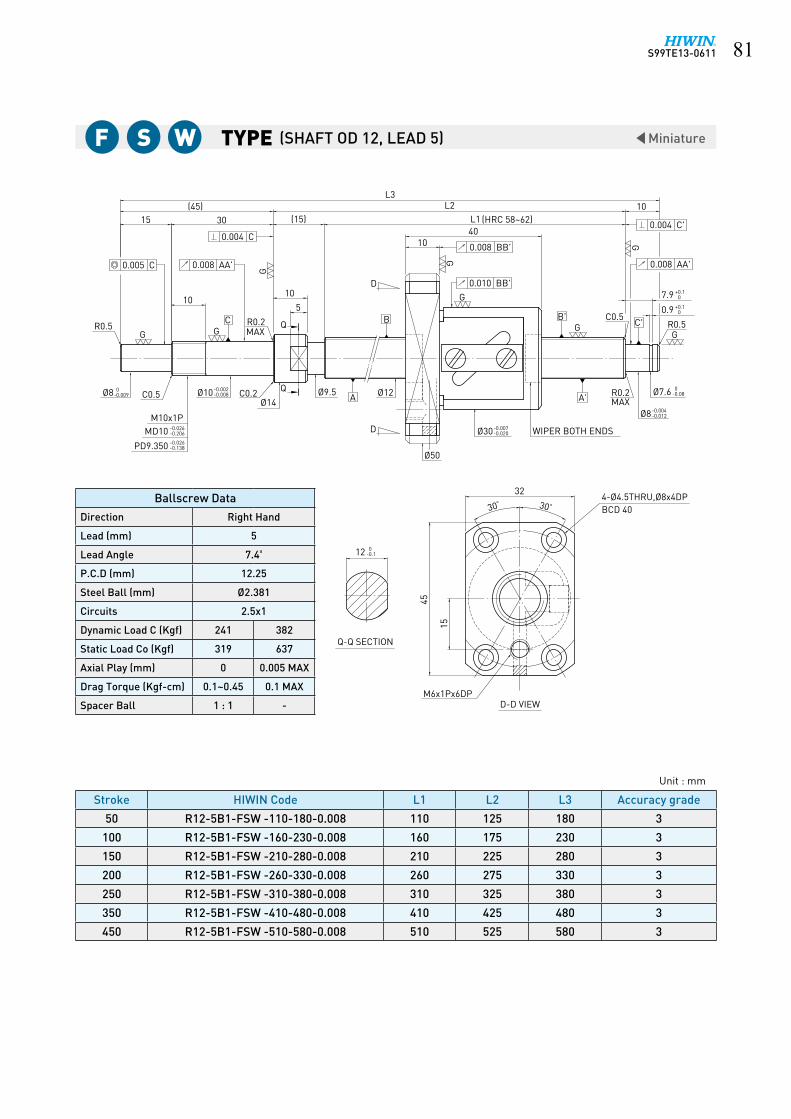
S99TE13-0611 ��
Type Miniature
10
10
30
Ø8 Ø10
Ø8
15(45)
L3
1040
Ø30
D-D VIEW
Q-Q SECTION
WIPER BOTH ENDS
32
15
45
L1(15)
C0.5
R0.5
Q
Q
C0.2
R0.2MAX
5
10
L2
R0.5C0.5
D
D
GG
G
G
G
GG
G
MAX
(HRC 58~62)
M6x1Px6DP
BCD 404-Ø4.5THRU,Ø8x4DP
A'
B'
R0.2
Ø50
C C'
Ø14Ø9.5
M10x1P
A
B
Ø12
0.005 C 0.008 AA'
0.004 C0.008 BB'
0.010 BB'
0.004 C'
0.008 AA'
7.9
0.9
+0.10
+0.10
Ø7.6 0-0.08
-0.004-0.012
-0.007-0.020
-0.002-0.008
0-0.009
-0.026-0.206
-0.026-0.138
MD10
PD9.350
12 0-0.1
30° 30°
Stroke HIWIN Code L1 L2 L3 Accuracy grade
50 R12-5B1-FSW -110-180-0.008 110 125 180 3
100 R12-5B1-FSW -160-230-0.008 160 175 230 3
150 R12-5B1-FSW -210-280-0.008 210 225 280 3
200 R12-5B1-FSW -260-330-0.008 260 275 330 3
250 R12-5B1-FSW -310-380-0.008 310 325 380 3
350 R12-5B1-FSW -410-480-0.008 410 425 480 3
450 R12-5B1-FSW -510-580-0.008 510 525 580 3
Ballscrew Data
Direction Right Hand
Lead (mm) 5
Lead Angle 7.4º
P.C.D (mm) 12.25
Steel Ball (mm) Ø2.381
Circuits 2.5x1
Dynamic Load C (Kgf) 241 382
Static Load Co (Kgf) 319 637
Axial Play (mm) 0 0.005 MAX
Drag Torque (Kgf-cm) 0.1~0.45 0.1 MAX
Spacer Ball 1 : 1 -
Unit : mm
F S W (SHAFT OD 12, LEAD 5)

S99TE13-0611��
Type Miniature
Stroke HIWIN Code L1 L2 L3 Accuracy grade
100 R12-10B1-FSW-160-230-0.008 160 175 230 3
150 R12-10B1-FSW-210-280-0.008 210 225 280 3
250 R12-10B1-FSW-310-380-0.008 310 325 380 3
350 R12-10B1-FSW-410-480-0.008 410 425 480 3
450 R12-10B1-FSW-510-580-0.008 510 525 580 3
Unit : mm
F S W (SHAFT OD 12, LEAD 10)
Ballscrew Data
Direction Right Hand
Lead (mm) 10
Lead Angle 14.57º
P.C.D (mm) 12.25
Steel Ball (mm) Ø2.381
Circuits 2.5x1
Dynamic Load C (Kgf) 241 382
Static Load Co (Kgf) 319 637
Axial Play (mm) 0 0.005 MAX
Drag Torque (Kgf-cm) 0.1~0.5 0.5 MAX
Spacer Ball 1 : 1 -
1050
3015(45)
L3
10
Ø8
Ø8
D-D VIEW
Q-Q SECTION
(OIL HOLE)
WIPER BOTH ENDS
15
324-Ø4.5THRU,Ø8x4DP
(15)
45
10L1
L2
MAX
R0.5C0.5
Q
510
Q
C0.2
R0.2MAX
R0.5
C0.5
(HRC 58~62)
D
G
G
G
G
G
R0.2Ø14
GC
G
C'G
A'
B'
A
B
M10x1PØ9.5
M6x1Px6DP
D
Ø12
Ø50
0.005 C
0.004 C
0.008 AA'
0.008 BB'
0.010 BB'
0.004 C'
0.008 AA'
7.90.9
+0.10
+0.10
0-0.08Ø7.6
-0.004-0.012
-0.007-0.020Ø30
-0.002-0.008Ø10
0-0.009
MD10PD9.350
-0.026-0.206-0.026-0.138
0-0.2512
BCD 4030° 30°
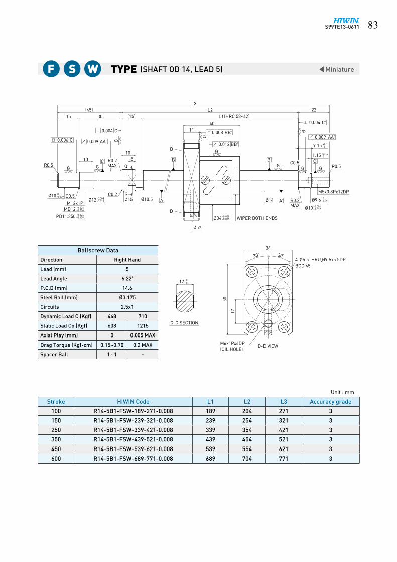
S99TE13-0611 ��
Type Miniature
Stroke HIWIN Code L1 L2 L3 Accuracy grade
100 R14-5B1-FSW-189-271-0.008 189 204 271 3
150 R14-5B1-FSW-239-321-0.008 239 254 321 3
250 R14-5B1-FSW-339-421-0.008 339 354 421 3
350 R14-5B1-FSW-439-521-0.008 439 454 521 3
450 R14-5B1-FSW-539-621-0.008 539 554 621 3
600 R14-5B1-FSW-689-771-0.008 689 704 771 3
Ballscrew Data
Direction Right Hand
Lead (mm) 5
Lead Angle 6.22º
P.C.D (mm) 14.6
Steel Ball (mm) Ø3.175
Circuits 2.5x1
Dynamic Load C (Kgf) 448 710
Static Load Co (Kgf) 608 1215
Axial Play (mm) 0 0.005 MAX
Drag Torque (Kgf-cm) 0.15~0.70 0.2 MAX
Spacer Ball 1 : 1 -
Unit : mm
F S W (SHAFT OD 14, LEAD 5)
10
4011
L23015
(45)L3
Ø10
Q-Q SECTION
34
17
D-D VIEW
G
(OIL HOLE)
WIPER BOTH ENDS
BCD 45
R0.5
22L1
C0.5
4-Ø5.5THRU,Ø9.5x5.5DP
50
(15)
R0.5
C0.5
R0.2MAX
C0.2 Q
Q
510
M6x1Px6DP
(HRC 58~62)
D
G
G
G
G
G
MAXR0.2Ø15
GC
G
C'G
A'
B'
A
B
M12x1PØ10.5
D
Ø14
Ø57
0.006 C
0.004 C
0.009 AA'
0.008 BB'
0.012 BB'
0.004 C'
0.009 AA'
9.15
1.15
+0.10
+0.140
M5x0.8Px12DP
Ø9.6 0-0.09
-0.004-0.012
-0.009-0.025Ø34
-0.003-0.011Ø12
0-0.009Ø10
-0.026-0.206
-0.026-0.138
MD12
PD11.350
12 0-0.1
30° 30°

S99TE13-0611��
Type Miniature
Ø34
10
Ø12Ø10
Ø10
4611
L23015
(45)L3
34
17
Q-Q SECTION
D-D VIEW(OIL HOLE)M6x1Px6DP
WIPER BOTH ENDS
BCD 454-Ø5.5THRU,Ø9.5X5.5DP
50
(15)
10
C0.2
MAXR0.2
Q
5R0.5
C0.5
R0.5
L122
C0.5
(HRC 58~62)
D
G
G
G
G
G
MAXR0.2Ø15
QGC
GC'
G
A'
B'
A
B
M12x1PØ10.5
D
Ø14
Ø57
0.006 C 0.009 AA'
0.004 C 0.008 BB'
0.012 BB'
0.004 C'
0.009 AA'
9.15
1.15
+0.10
+0.140
M5x0.8Px12DP
Ø9.6 0-0.09
-0.004-0.012
-0.009-0.025
-0.003-0.011
0-0.009
-0.026-0.206
-0.026-0.138
MD12
PD11.350
12 0-0.1
30° 30°
Stroke HIWIN Code L1 L2 L3 Accuracy grade
100 R14-8B1-FSW-189-271-0.008 189 204 271 3
150 R14-8B1-FSW-239-321-0.008 239 254 321 3
200 R14-8B1-FSW-289-371-0.008 289 304 371 3
250 R14-8B1-FSW-339-421-0.008 339 354 421 3
300 R14-8B1-FSW-389-471-0.008 389 404 471 3
350 R14-8B1-FSW-439-521-0.008 439 454 521 3
400 R14-8B1-FSW-489-571-0.008 489 504 571 3
450 R14-8B1-FSW-539-621-0.008 539 554 621 3
500 R14-8B1-FSW-589-671-0.008 589 604 671 3
550 R14-8B1-FSW-639-721-0.008 639 654 721 3
600 R14-8B1-FSW-689-771-0.008 689 704 771 3
700 R14-8B1-FSW-789-871-0.008 789 804 871 3
Unit : mm
F S W (SHAFT OD 14, LEAD 8)
Ballscrew Data
Direction Right Hand
Lead (mm) 8
Lead Angle 9.89º
P.C.D (mm) 14.6
Steel Ball (mm) Ø3.175
Circuits 2.5x1
Dynamic Load C (Kgf) 448 710
Static Load Co (Kgf) 608 1215
Axial Play (mm) 0 0.005 MAX
Drag Torque (Kgf-cm) 0.15~0.79 0.24 MAX
Spacer Ball 1 : 1 -
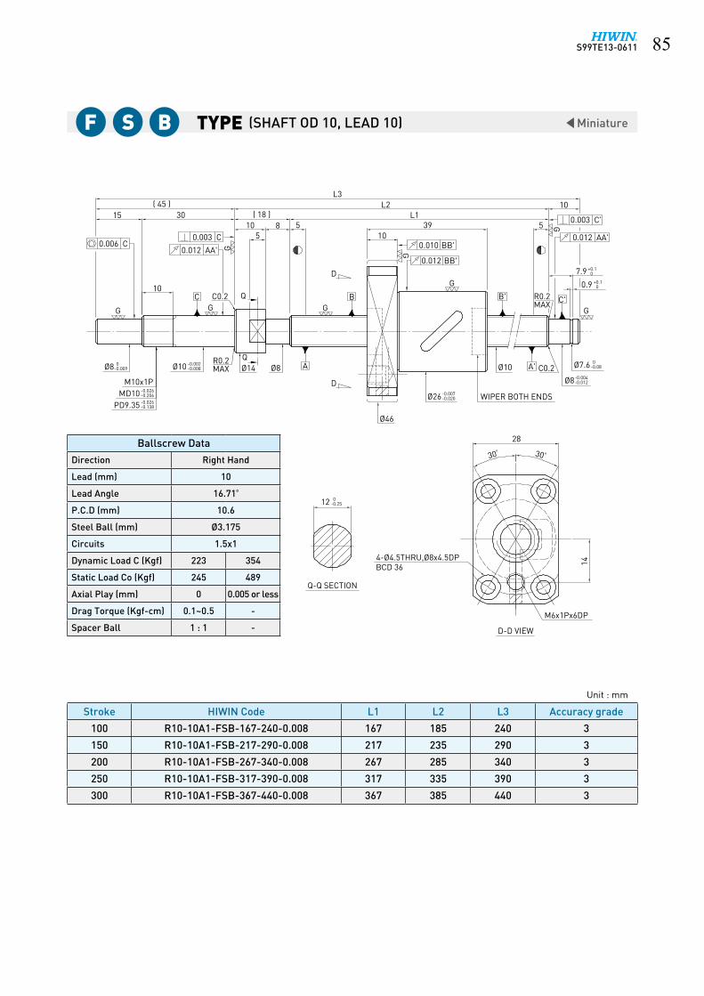
S99TE13-0611 ��
Type Miniature
0.006 C
15 30( 45 )
0.003 C
0.012 AA' G( 18 )
105
8 5
G
10C
GC0.2 Q
D
GB
L3L2
L1
1039
0.010 BB'
0.012 BB'
G
5 G
10
0.003 C'
0.012 AA'
B' R0.2MAX C'
G
7.9 +0.10
+0.100.9
Ø7.6 0-0.08
Ø8-0.004-0.012
C0.2A'Ø10
WIPER BOTH ENDSØ26-0.007-0.020
Ø46
D
AØ8QØ14
R0.2MAXØ10 -0.002
-0.008Ø8 0-0.009
M10x1PMD10 -0.026
-0.206-0.026-0.138PD9.35
12 0-0.25
Q-Q SECTION
BCD 364-Ø4.5THRU,Ø8x4.5DP
D-D VIEW
28
14
M6x1Px6DP
30° 30°
G
Stroke HIWIN Code L1 L2 L3 Accuracy grade
100 R10-10A1-FSB-167-240-0.008 167 185 240 3
150 R10-10A1-FSB-217-290-0.008 217 235 290 3
200 R10-10A1-FSB-267-340-0.008 267 285 340 3
250 R10-10A1-FSB-317-390-0.008 317 335 390 3
300 R10-10A1-FSB-367-440-0.008 367 385 440 3
Ballscrew Data
Direction Right Hand
Lead (mm) 10
Lead Angle 16.71º
P.C.D (mm) 10.6
Steel Ball (mm) Ø3.175
Circuits 1.5x1
Dynamic Load C (Kgf) 223 354
Static Load Co (Kgf) 245 489
Axial Play (mm) 0 0.005 or less
Drag Torque (Kgf-cm) 0.1~0.5 -
Spacer Ball 1 : 1 -
Unit : mm
F S B (SHAFT OD 10, LEAD 10)

S99TE13-0611��
Type Standard
1010L1 (HRC 58~62)
1010
3015 (15)L2(45)
5
C 5111
34
22L3
5017
Q-Q SECTION
D-D VIEW
OIL HOLE 6
2-M6x1Px6DP
BCD 454-Ø5.5THRU,Ø9.5x5.5DP
G G
A
G
B
G
G
GG
G
GC0.5
C0.2Ø15Q
Ø12 Ø15
D
Ø57
M5x0.8Px12DPMAXR0.2
D
C
A'
C'B'
MAXR0.2
Q
M12x1P
0.004
0.014 AA'0.009 C
R0.5
0.011 BB'
0.015 BB'
0.004 C'
0.014 AA'
R0.5
9.151.15
+0.10
+0.140
Ø9.6Ø10
0-0.09
-0.004-0.012
-0.009-0.025Ø34
Ø12 -0.003-0.011
0-0.009Ø10 C0.5
MD12PD11.35
-0.026-0.206-0.026-0.144
0-0.2512
30°30°
WIPER BOTH ENDS
6.4 End Machining Ground Ballscrew Series
Stroke HIWIN Code L1 L2 L3 Accuracy grade
100 R15-10B1-FSW-189-271-0.018 189 204 271 5
150 R15-10B1-FSW-239-321-0.018 239 254 321 5
200 R15-10B1-FSW-289-371-0.018 289 304 371 5
250 R15-10B1-FSW-339-421-0.018 339 354 421 5
300 R15-10B1-FSW-389-471-0.018 389 404 471 5
350 R15-10B1-FSW-439-521-0.018 439 454 521 5
400 R15-10B1-FSW-489-571-0.018 489 504 571 5
450 R15-10B1-FSW-539-621-0.018 539 554 621 5
500 R15-10B1-FSW-589-671-0.018 589 604 671 5
550 R15-10B1-FSW-639-721-0.018 639 654 721 5
600 R15-10B1-FSW-689-771-0.018 689 704 771 5
700 R15-10B1-FSW-789-871-0.018 789 804 871 5
800 R15-10B1-FSW-889-971-0.018 889 904 971 5
1000 R15-10B1-FSW-1089-1171-0.018 1089 1104 1171 5
Unit : mm
F S W (SHAFT OD 15, LEAD 10)
Ballscrew Data
Direction Right Hand
Lead (mm) 10
Lead Angle 11.53º
P.C.D (mm) 15.6
Steel Ball (mm) Ø3.175
Circuits 2.5x1
Dynamic Load C (Kgf) 460 729
Static Load Co (Kgf) 645 1290
Axial Play (mm) 0 0.005 MAX
Drag Torque (Kgf-cm) 0.15~0.79 0.24 MAX
Spacer Ball 1 : 1 -
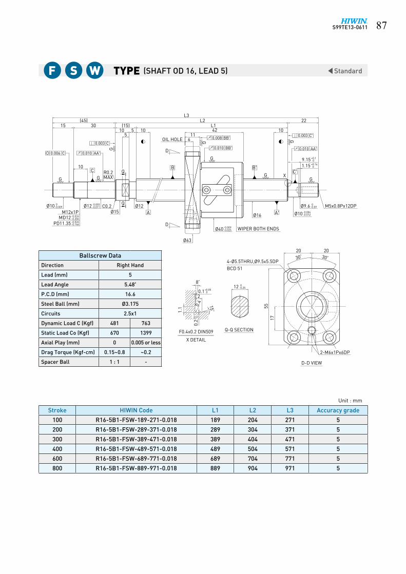
S99TE13-0611 ��
Type Standard
(45) L2
1755
30° 30°
0+0.19.15
-0.25 012
5
G
GG
G
G
L3
30
10
1522
L1
G
10 5 10 10
G
G
20 20
611
42
0+0.05
8°
20.1
15°
0.4
1.1
F0.4x0.2 DIN509
Q
Q
X DETAIL
Ø63
4-Ø5.5THRU,Ø9.5x5.5DP
2-M6x1Px6DP
-0.025-0.009Ø40
Ø16
M5x0.8Px12DP-0.011-0.003Ø12 Ø12
Ø15-0.09 0Ø9.6
-0.012-0.004Ø10
-0.009 0Ø10
-0.144-0.026PD11.35-0.206-0.026MD12
M12x1P
D
D
OIL HOLE
0+0.141.15
MAX
C0.2
R0.2
(15)
Q-Q SECTION
BCD 51
C C'
0.003 C
0.010 AA'0.006 C
0.003 C'
0.010 AA'
B
A
B'
A'
0.008 BB'
0.010 BB'
X
D-D VIEW
+0.1 0
0.2
+0.1 0
0.2
WIPER BOTH ENDS
Stroke HIWIN Code L1 L2 L3 Accuracy grade
100 R16-5B1-FSW-189-271-0.018 189 204 271 5
200 R16-5B1-FSW-289-371-0.018 289 304 371 5
300 R16-5B1-FSW-389-471-0.018 389 404 471 5
400 R16-5B1-FSW-489-571-0.018 489 504 571 5
600 R16-5B1-FSW-689-771-0.018 689 704 771 5
800 R16-5B1-FSW-889-971-0.018 889 904 971 5
Ballscrew Data
Direction Right Hand
Lead (mm) 5
Lead Angle 5.48º
P.C.D (mm) 16.6
Steel Ball (mm) Ø3.175
Circuits 2.5x1
Dynamic Load C (Kgf) 481 763
Static Load Co (Kgf) 670 1399
Axial Play (mm) 0 0.005 or less
Drag Torque (Kgf-cm) 0.15~0.8 ~0.2
Spacer Ball 1 : 1 -
Unit : mm
(SHAFT OD 16, LEAD 5)F S W

S99TE13-0611��
Type Standard
BCD 51
45°
D-D VIEW
DP
Q-Q SECTION
017-0.25 (OIL HOLE)M6x1Px6
45 °
L3
PD14.35MD15
0.009 C
Ø12-0.011 0
G
20
MAX Q
Ø19.5Ø15M15x1P C0.3-0.012
-0.144-0.026-0.206-0.026
-0.004
G
A
D
Q
40
0.005 C
0.018 AA'
15C R0.2
G
9
(60)(25)
INCOMPLETETHREAD
2MAX
107
D
B
24
Ø15
0.005 C'
0.014 AA'
WIPER BOTH ENDS
Ø63
6-Ø5.5THRU,Ø9.5x5.5 DP
-0.025-0.009Ø40
Ø20 C0.3A'
G
L1
0.010 BB'11
G
0.012 BB'
G
49
L2
B' C'
10 G
DPM6x1Px15Ø14.3-0.11
-0.012-0.004
0
G
+0.1
+0.14 0
10.151.15
0
25
Stroke HIWIN Code L1 L2 L3 Accuracy grade
150 R20-4B2-FSW-225-335-0.018 225 250 335 5
200 R20-4B2-FSW-275-385-0.018 275 300 385 5
300 R20-4B2-FSW-375-485-0.018 375 400 485 5
400 R20-4B2-FSW-475-585-0.018 475 500 585 5
500 R20-4B2-FSW-575-685-0.018 575 600 685 5
350 R15-10B1-FSW-439-521-0.018 439 454 521 5
Unit : mm
F S W (SHAFT OD 20, LEAD 4)
Ballscrew Data
Direction Right Hand
Lead (mm) 4
Lead Angle 3.6º
P.C.D (mm) 20.25
Steel Ball (mm) Ø2.381
Circuits 2.5x2
Dynamic Load C (Kgf) 561
Static Load Co (Kgf) 1085
Axial Play (mm) 0
Drag Torque (Kgf-cm) 0.12~0.68
Spacer Ball 1 : 1

S99TE13-0611 ��
Type Standard
X DETAIL
M6x1Px6DP
6-Ø5.5THRU,Ø9.5x5.5DP
(OIL HOLE)
-0.025-0.009Ø44 WIPER BOTH ENDS
Ø20 M6x1Px15DP-0.11 0Ø14.3
-0.012-0.004Ø15
D
D
0+0.141.15
Ø67
INCOMPLETE
-0.012-0.004Ø15 Ø19.5
-0.144-0.026PD14.35-0.206-0.026MD15
M15x1P-0.011 0Ø12 C0.3
MAXR0.2
Q-Q SECTION
Q
Q
C0.3
2MAX
THREAD
BCD 55
C C'
0.005 C
0.018 AA'0.009 C
0.005 C'
0.014 AA'
B
A
B'
A'
0.010 BB'
0.012 BB'
X
D-D VIEW
F0.4x0.2DIN509
0.2
1.1 0.
4 15°
0.12
8°
+0.050
G
GG
G
GG
G
G
10.15 +0.1 0
17 0-0.25
79
(60)L3
40
15
2025L2
L1(25)10 10
45° 45°
26
1156
0+0.1 0+0.1
Stroke HIWIN Code L1 L2 L3 Accuracy grade
150 R20-5B2-FSW-225-335-0.018 225 250 335 5
200 R20-5B2-FSW-275-385-0.018 275 300 385 5
300 R20-5B2-FSW-375-485-0.018 375 400 485 5
400 R20-5B2-FSW-475-585-0.018 475 500 585 5
500 R20-5B2-FSW-575-685-0.018 575 600 685 5
700 R20-5B2-FSW-775-885-0.018 775 800 885 5
Ballscrew Data
Direction Right Hand
Lead (mm) 5
Lead Angle 4.42º
P.C.D (mm) 20.6
Steel Ball (mm) Ø3.175
Circuits 2.5x2
Dynamic Load C (Kgf) 952
Static Load Co (Kgf) 1732
Axial Play (mm) 0
Drag Torque (Kgf-cm) 0.28~1.32
Spacer Ball 1 : 1
Unit : mm
(SHAFT OD 20, LEAD 5)F S W

S99TE13-0611�0
Type Standard
30°30°
46
1354
L1 (HRC 58~62)
155
L2
10 10
A
4020(60) 25
L3
15
G G
G
G
G
G
G
G
(25)
6624
OIL HOLE 6
Q-Q SECTION
D-D VIEW
2-M6x1Px6DP
BCD 594-Ø6.6THRU,Ø11x6.5DP
WIPER BOTH ENDS
C0.3
R0.5
Ø19.5
R0.5
C0.5
C0.3
Ø16.5
Ø74
Ø20M6x1Px15DP
Q
B'B
MAXR0.2
D
C'
M15x1P
CQ
A'
D0.009 C 0.014 AA'
0.004 C
R0.2MAX
0.011 BB'
0.015 BB'
0.004 C'
0.014 AA'
10.15 +0.10
+0.1401.15
Ø14.3 0-0.11
-0.004-0.012Ø15
Ø46-0.009-0.025
-0.004-0.012Ø15Ø12 0
-0.011
MD15PD14.35
-0.026-0.206-0.026-0.144
0-0.2517
Stroke HIWIN Code L1 L2 L3 Accuracy grade
200 R20-10B1-FSW- 289 - 399-0.018 289 314 399 5
300 R20-10B1-FSW- 389 - 499-0.018 389 414 499 5
400 R20-10B1-FSW- 489 - 599-0.018 489 514 599 5
500 R20-10B1-FSW- 589 - 699-0.018 589 614 699 5
600 R20-10B1-FSW- 689 - 799-0.018 689 714 799 5
700 R20-10B1-FSW- 789 - 899-0.018 789 814 899 5
800 R20-10B1-FSW- 889 -999-0.018 889 914 999 5
900 R20-10B1-FSW- 989 -1099-0.018 989 1014 1099 5
1000 R20-10B1-FSW- 1089 -1199-0.018 1089 1114 1199 5
1100 R20-10B1-FSW- 1189 - 1299-0.018 1189 1214 1299 5
1400 R20-10B1-FSW- 1289 -1399-0.018 1289 1314 1399 5
Unit : mm
F S W (SHAFT OD 20, LEAD 10)
Ballscrew Data
Direction Right Hand
Lead (mm) 10
Lead Angle 8.7º
P.C.D (mm) 20.8
Steel Ball (mm) Ø3.969
Circuits 2.5x1
Dynamic Load C (Kgf) 718 1139
Static Load Co (Kgf) 1094 2187
Axial Play (mm) 0 0.005 MAX
Drag Torque (Kgf-cm) 0.2~1.2 0.3 MAX
Spacer Ball 1 : 1 -

S99TE13-0611 ��
Type Standard
A
B
136310
25
15
4020(60)
155
G G
G
G
G
G
G
G
10
L3
L1 (HRC 58~62)L2
(25)
OIL HOLE 7
Q-Q SECTION
D-D VIEW
2-M6x1Px6DP
BCD 594-Ø6.6THRU,Ø11x6.5DP
WIPER BOTH ENDS
30°30°
46
6624
Ø74
Ø20M6x1Px15DPC0.5 C0.3
Ø19.5 Ø16.5
R0.5R0.5
Q
C0.3
D
D
C C'
A'
B'Q
M15x1P
0.009 C
R0.2MAX
0.004 C
0.014 AA'
0.011 BB'
0.015 BB'
0.004 C'
0.014 AA'
10.15 +0.10
+0.1401.15
Ø14.3 0-0.11
-0.004-0.012Ø15
R0.2MAX
Ø46 -0.009-0.025
-0.004-0.012Ø15
Ø12 0-0.011
MD15 -0.026-0.206
PD14.35 -0.026-0.144
17 0-0.25
Stroke HIWIN Code L1 L2 L3 Accuracy grade
200 R20-20A1-FSW-310-420-0.018 310 335 420 5
300 R20-20A1-FSW-410-520-0.018 410 435 520 5
400 R20-20A1-FSW-510-620-0.018 510 535 620 5
500 R20-20A1-FSW-610-720-0.018 610 635 720 5
600 R20-20A1-FSW-710-820-0.018 710 735 820 5
700 R20-20A1-FSW-810-920-0.018 810 835 920 5
800 R20-20A1-FSW-910-1020-0.018 910 935 1020 5
900 R20-20A1-FSW-1010-1120-0.018 1010 1035 1120 5
1000 R20-20A1-FSW-1110-1220-0.018 1110 1135 1220 5
1100 R20-20A1-FSW-1210-1320-0.018 1210 1235 1320 5
1400 R20-20A1-FSW-1510-1620-0.018 1510 1535 1620 5
Ballscrew Data
Direction Right Hand
Lead (mm) 20
Lead Angle 17.01º
P.C.D (mm) 20.8
Steel Ball (mm) Ø3.969
Circuits 1.5x1
Dynamic Load C (Kgf) 453 719
Static Load Co (Kgf) 641 1280
Axial Play (mm) 0 0.005 MAX
Drag Torque (Kgf-cm) 0.2~1.2 0.3 MAX
Spacer Ball 1 : 1 -
Unit : mm
(SHAFT OD 20, LEAD 20)F S W

S99TE13-0611��
Type Standard
16
(30)
0+0.141.35
0+0.115.35
-0.35 022
1014
G
GG
G
G
(80)L3
53
16
2753L2
L1
G
15
45 ° 45°
G
G
26
1148
Ø69
Q
6-Ø5.5THRU,Ø9.5x5.5DP
M6x1Px8DP
-0.025-0.009Ø46 WIPER BOTH ENDS
Ø25-0.014-0.005Ø20
-0.144-0.026PD19.35-0.206-0.026MD20
M20x1P
INCOMPLETE2MAX
QC0.3
MAXR0.2
-0.21 0Ø19
-0.144-0.026PD19.35
-0.206-0.026MD20
M20x1PC0.3
R0.2MAX
-0.014-0.005Ø20
-0.011 0Ø15
15
THREAD
Q-Q SECTION
D
D
BCD 58
C C'
0.005 C
0.016 AA'0.007 C
0.005 C'
0.016 AA'
B
A
B'
A'
0.011 BB'0.015 BB'
D-D VIEW
Stroke HIWIN Code L1 L2 L3 Accuracy grade
150 R25-4B2-FSW-220-349-0.018 220 250 349 5
200 R25-4B2-FSW-270-399-0.018 270 300 399 5
300 R25-4B2-FSW-370-499-0.018 370 400 499 5
400 R25-4B2-FSW-470-599-0.018 470 500 599 5
500 R25-4B2-FSW-570-733-0.018 570 600 733 5
Unit : mm
F S W (SHAFT OD 25, LEAD 4)
Ballscrew Data
Direction Right Hand
Lead (mm) 4
Lead Angle 2.89º
P.C.D (mm) 25.25
Steel Ball (mm) Ø2.381
Circuits 2.5x2
Dynamic Load C (Kgf) 622
Static Load Co (Kgf) 1376
Axial Play (mm) 0
Drag Torque (Kgf-cm) 0.15~0.85
Spacer Ball 1 : 1

S99TE13-0611 ��
Type Standard
L3L2
L1
-0.35 022
14(30)
G
(80)27 53
16
G
G
115510 15
G
G
45 ° 45°
28
0+0.115.35
G
53
15
G
G
16
0+0.05
8°
20.1
15°
0.4
1.1
0.2
F0.4x0.2DIN509
X DETAIL
0+0.141.35
M20x1P
-0.144-0.026PD19.35
-0.206-0.026MD20
-0.21 0Ø19 -0.014
-0.005Ø20
D
Q INCOMPLETE2MAX
THREAD
-0.025-0.009Ø50
M6x1Px6DP(OIL HOLE)
Ø73
D
Q
-0.014-0.005Ø20
-0.206-0.026MD20
M20x1P
-0.144-0.026PD19.35
-0.011 0Ø15
6-Ø5.5THRU,Ø9.5x5.5DP
WIPER BOTH ENDS
Ø25
Q-Q SECTION
C C'
0.005 C
0.016 AA'0.007 C
0.005 C'
0.016 AA'
B
A
B'
A'
0.013 BB'
0.015 BB'
BCD 61
XX
D-D VIEW
+0.1 0+0.1 0
Stroke HIWIN Code L1 L2 L3 Accuracy grade
150 R25-5B2-FSW-220-349-0.018 220 250 349 5
200 R25-5B2-FSW-270-399-0.018 270 300 399 5
300 R25-5B2-FSW-370-499-0.018 370 400 499 5
400 R25-5B2-FSW-470-599-0.018 470 500 599 5
500 R25-5B2-FSW-570-733-0.018 570 600 733 5
600 R25-5B2-FSW-670-833-0.018 670 700 833 5
700 R25-5B2-FSW-770-933-0.018 770 800 933 5
900 R25-5B2-FSW-970-1133-0.018 970 1000 1133 5
1000 R25-5B2-FSW-1170-1333-0.018 1170 1200 1333 5
Ballscrew Data
Direction Right Hand
Lead (mm) 5
Lead Angle 3.56º
P.C.D (mm) 25.6
Steel Ball (mm) Ø3.175
Circuits 2.5x2
Dynamic Load C (Kgf) 1073
Static Load Co (Kgf) 2209
Axial Play (mm) 0
Drag Torque (Kgf-cm) 0.36~1.44
Spacer Ball 1 : 1
Unit : mm
(SHAFT OD 25, LEAD 5)F S W

S99TE13-0611��
Type Standard
L3L2
L1
-0.35 022
G
(80)5327
16
G G
11621014
(30)15
G
G
45°45 °
29
0+0.115.35
53
15
G
G
G
16
0+0.05
8°
20.1
15°
0.4
1.1
0.2
F0.4x0.2DIN509
X DETAIL
0+0.141.35
-0.014-0.005Ø20
-0.144-0.026PD19.35
-0.206-0.026MD20
M20x1PC0.3Ø25
-0.21 0Ø19
D
QINCOMPLETE
2MAX
THREAD
Ø76-0.029-0.010Ø53D
QC0.3-0.014
-0.005Ø20-0.206-0.026MD20
M20x1P
-0.144-0.026PD19.35
-0.011 0Ø15
6-Ø5.5THRU,Ø9.5x5.5DP
M6x1Px6DP(OIL HOLE)
WIPER BOTH ENDS
Q-Q SECTION
C C'
0.005 C
0.016 AA'0.007 C
0.005 C'
0.016 AA'
B
A
B'
A'
0.013 BB'
0.019 BB'
BCD 64
D-D VIEW
X X
+0.1 0+0.1 0
Stroke HIWIN Code L1 L2 L3 Accuracy grade
250 R25-6B2-FSW-370-533-0.018 370 400 533 5
450 R25-6B2-FSW-570-733-0.018 570 600 733 5
650 R25-6B2-FSW-770-933-0.018 770 800 933 5
Unit : mm
F S W (SHAFT OD 25, LEAD 6)
Ballscrew Data
Direction Right Hand
Lead (mm) 6
Lead Angle 4.23º
P.C.D (mm) 25.8
Steel Ball (mm) Ø3.969
Circuits 2.5x2
Dynamic Load C (Kgf) 1453
Static Load Co (Kgf) 2761
Axial Play (mm) 0
Drag Torque (Kgf-cm) 0.42~2.4
Spacer Ball 1 : 1

S99TE13-0611 ��
Type Standard
L3L2
L181
-0.35 022
G
(80)5327
16
G G
151014
(30)15
G
G
45 ° 45°
32
0+0.115.35
53
15
G
G
G
16
0+0.05
8°
20.1
15°
0.4
1.1
0.2
F0.4x0.2DIN509
X DETAIL
0+0.141.35
-0.014-0.005Ø20
-0.144-0.026PD19.35
-0.206-0.026MD20
M20x1PC0.3Ø25
WIPER BOTH ENDS-0.21 0Ø19
D
QINCOMPLETE2MAX
THREAD
-0.029-0.010Ø58
Ø85
D
QC0.3-0.014
-0.005Ø20
-0.144-0.026PD19.35-0.206-0.026MD20
M20x1P-0.011 0Ø15
6-Ø6.6THRU,Ø11x6.5DP
M6x1Px6DP(OIL HOLE)
Q-Q SECTION
C C'
0.005 C
0.016 AA'0.007 C
0.005 C'
0.016 AA'
B
A
B'
A'
0.013 BB'
0.019 BB'
BCD 71
XX
D-D VIEW
+0.1 0+0.1 0
Stroke HIWIN Code L1 L2 L3 Accuracy grade
250 R25-10A2-FSW-370-533-0.018 370 400 533 5
450 R25-10A2-FSW-570-733-0.018 570 600 733 5
650 R25-10A2-FSW-770-933-0.018 770 800 933 5
850 R25-10A2-FSW-970-1133-0.018 970 1000 1133 5
1050 R25-10A2-FSW-1170-1333-0.018 1170 1200 1333 5
Ballscrew Data
Direction Right Hand
Lead (mm) 10
Lead Angle 6.98º
P.C.D (mm) 26
Steel Ball (mm) Ø4.763
Circuits 1.5x2
Dynamic Load C (Kgf) 1164
Static Load Co (Kgf) 1927
Axial Play (mm) 0
Drag Torque (Kgf-cm) 0.42~2.4
Spacer Ball 1 : 1
Unit : mm
(SHAFT OD 25, LEAD 10)F S W

S99TE13-0611��
Type Standard
L2L3
L156
-0.35 022
(80)
G
5327
16
G G
(30)1014 15
G
12
G
45°45 °
31
65(12) 53
15
G
0+0.115.35
16
G
G
C0.3 0+0.141.35
R0.2 -0.014-0.005Ø20Ø25Ø28 M20x1P
MAX-0.21 0Ø19
WIPER BOTH ENDS
-0.206-0.026MD20
-0.144-0.026PD19.35
Ø25Q
Q
D
C0.3
R0.2M20x1P
-0.014-0.005Ø20-0.011
0Ø15
-0.029-0.010Ø55
Ø85
DMAX
-0.206-0.026MD20-0.144-0.026PD19.35
6-Ø6.6THRU,Ø11x6.5DP
M6x1Px6DP
Q-Q SECTION
(OIL HOLE)
C C'
0.005 C
0.016 AA'0.007 C
0.005 C'
0.016 AA'
B
A
B'
A'
0.013 BB'
0.019 BB'
BCD 69
D-D VIEW
Stroke HIWIN Code L1 L2 L3 Accuracy grade
200 R28-5B2-FSW-270-399-0.018 270 300 399 5
300 R28-5B2-FSW-370-499-0.018 370 400 499 5
400 R28-5B2-FSW-470-599-0.018 470 500 599 5
450 R28-5B2-FSW-558-733-0.018 558 600 733 5
650 R28-5B2-FSW-758-933-0.018 758 800 933 5
850 R28-5B2-FSW-958-1133-0.018 958 1000 1133 5
1050 R28-5B2-FSW-1158-1333-0.018 1158 1200 1333 5
Unit : mm
F S W (SHAFT OD 28, LEAD 5)
Ballscrew Data
Direction Right Hand
Lead (mm) 5
Lead Angle 3.19º
P.C.D (mm) 28.6
Steel Ball (mm) Ø3.175
Circuits 2.5x2
Dynamic Load C (Kgf) 1124
Static Load Co (Kgf) 2466
Axial Play (mm) 0
Drag Torque (Kgf-cm) 0.3~1.7
Spacer Ball 1 : 1

S99TE13-0611 ��
Type Standard
L2L3
L163
-0.35 022
14
(30)(80)
27 53
16
G G
G
10
15
G
12
G
45° 45°
31
5312
15
G
0+0.115.35
16
G
G
0+0.05
8°
20.1
15°
0.4
1.1
0.2
F0.4x0.2DIN509X DETAIL
0+0.141.35
M20x1P-0.21 0Ø19
WIPER BOTH ENDS -0.144-0.026PD19.35
-0.206-0.026MD20
Ø28 Ø25 C0.3 -0.014-0.005Ø20
D
Q
Q
-0.029-0.010Ø55
Ø85
D-0.206-0.026MD20
M20x1P
-0.144-0.026PD19.35
-0.014-0.005Ø20-0.011
0Ø15 Ø25C0.3
6-Ø6.6THRU,Ø11x6.5DP
M6x1Px6DP
Q-Q SECTION
(OIL HOLE)
C C'
0.005 C
0.016 AA'0.007 C
0.005 C'
0.016 AA'
B
A
B'
A'
0.013 BB'
0.019 BB'
BCD 69
D-D VIEW
X X
+0.1 0+0.1 0
Stroke HIWIN Code L1 L2 L3 Accuracy grade
250 R28-6B2-FSW-370-499-0.018 370 400 499 5
450 R28-6B2-FSW-570-699-0.018 570 600 699 5
650 R28-6B2-FSW-758-933-0.018 758 800 933 5
850 R28-6B2-FSW-958-1133-0.018 958 1000 1133 5
1050 R28-6B2-FSW-1158-1333-0.018 1158 1200 1333 5
Ballscrew Data
Direction Right Hand
Lead (mm) 6
Lead Angle 3.82º
P.C.D (mm) 28.6
Steel Ball (mm) Ø3.175
Circuits 2.5x2
Dynamic Load C (Kgf) 1124
Static Load Co (Kgf) 2466
Axial Play (mm) 0
Drag Torque (Kgf-cm) 0.36~2.04
Spacer Ball 1 : 1
Unit : mm
(SHAFT OD 28, LEAD 6)F S W

S99TE13-0611��
Type Standard
0+0.116.35
-0.35 027
12 15
G
GG
G
G
(95)L3
62
20
3362
20
L2L1
G
(35)15 15
45 ° 45°
G
G
32
1256
0+0.05
8°
20.1
15°
0.4
1.1
0.2
F0.4x0.2DIN509
X DETAIL
6-Ø6.6THRU,Ø11x6.5DP
D
M25x1.5P-0.268-0.032MD25-0.182-0.032PD24.026 -0.029
-0.010Ø58 WIPER BOTH ENDS
Ø85
-0.21 0Ø23.9Ø32 -0.014
-0.005Ø25
-0.182-0.032PD24.026
-0.268-0.032MD25
M25x1.5P
M6x1Px6DP
-0.014-0.005Ø25-0.013
0Ø20
INCOMPLETE 0
+0.141.35
D
Q
Q
2MAX
THREAD
Q-Q SECTION
(OIL HOLE)
C C'
0.005 C
0.017 AA'0.007 C 0.014 AA'0.005 C'
B
A
B'
A'
0.013 BB'
0.019 BB'
BCD 71
D-D VIEW
XX
+0.1 0+0.1 0
Stroke HIWIN Code L1 L2 L3 Accuracy grade
150 R32-5B2-FSW-265-415-0.018 265 300 415 5
250 R32-5B2-FSW-365-515-0.018 365 400 515 5
350 R32-5B2-FSW-465-615-0.018 465 500 615 5
450 R32-5B2-FSW-565-715-0.018 565 600 715 5
550 R32-5B2-FSW-665-857-0.018 665 700 857 5
650 R32-5B2-FSW-765-957-0.018 765 800 957 5
850 R32-5B2-FSW-965-1157-0.018 965 1000 1157 5
1050 R32-5B2-FSW-1165-1357-0.018 1165 1200 1357 5
Unit : mm
F S W (SHAFT OD 32, LEAD 5)
Ballscrew Data
Direction Right Hand
Lead (mm) 5
Lead Angle 2.79º
P.C.D (mm) 32.6
Steel Ball (mm) Ø3.175
Circuits 2.5x2
Dynamic Load C (Kgf) 1188
Static Load Co (Kgf) 2833
Axial Play (mm) 0
Drag Torque (Kgf-cm) 0.48~1.92
Spacer Ball 1 : 1

S99TE13-0611 ��
Type Standard
0+0.116.35
-0.35 027
1215
G
GG
G
G
(95)L3
62
20
3362
20
L2L1
G
(35)15 15
45 ° 45°
G
G
34
1263
0+0.05
8°
20.1
15°
0.4
1.1
0.2
F0.4x0.2DIN509
X DETAIL
Ø89-0.029-0.010Ø62 WIPER BOTH ENDS
Ø32
-0.014-0.005Ø25
-0.21 0Ø23.9
0+0.141.35
INCOMPLETE
-0.014-0.005Ø25-0.013
0Ø20
-0.182-0.032PD24.026
-0.268-0.032MD25
M25x1.5P
-0.182-0.032PD24.026-0.268-0.032MD25
M25x1.5P
D
D
6-Ø6.6THRU,Ø11x6.5DP
M6x1PxDP
Q
Q
2MAX
THREAD
Q-Q SECTION
(OIL HOLE)
C C'
0.005 C
0.020 AA'0.007 C
0.005 C'
0.020 AA'
B
A
B'
A'
0.015 BB'
0.019 BB'
BCD 75
D-D VIEW
X X
+0.1 0+0.1 0
Stroke HIWIN Code L1 L2 L3 Accuracy grade
250 R32-6B2-FSW-365-515-0.018 365 400 515 5
450 R32-6B2-FSW-565-715-0.018 565 600 715 5
650 R32-6B2-FSW-765-957-0.018 765 800 957 5
850 R32-6B2-FSW-965-1157-0.018 965 1000 1157 5
1050 R32-6B2-FSW-1165-1357-0.018 1165 1200 1357 5
1350 R32-6B2-FSW-1465-1657-0.018 1465 1500 1657 5
Ballscrew Data
Direction Right Hand
Lead (mm) 6
Lead Angle 3.33º
P.C.D (mm) 32.8
Steel Ball (mm) Ø3.969
Circuits 2.5x2
Dynamic Load C (Kgf) 1610
Static Load Co (Kgf) 3510
Axial Play (mm) 0
Drag Torque (Kgf-cm) 0.48~2.72
Spacer Ball 1 : 1
Unit : mm
(SHAFT OD 32, LEAD 6)F S W

S99TE13-0611�00
Type Standard
-0.009-0.025
1010
G
G
G
G
GG
22L1 (HRC 58~62)3015
10
21
50
+0.1
(45)
1155
G
G
30°30°
24 M
AX
19 MAX
34
1750
L2(20)
L3
0+0.14
0.011 BB'
10
C0.004
AA'C0.009
Ø10
Ø10 Ø12
Ø34
OIL HOLE 6
Q-Q SECTION
D-D VIEW
2-M6x1Px6DP
BCD 454-Ø5.5THRU,Ø9.5x5.5DP
WIPER BOTH ENDS
B'B C0.5
Ø16
Ø57
Ø15
QC0.2C0.5
Ø13
R0.5
M5x0.8Px12DP
R0.5
D
D
QC'C
A'AM12x1P
R0.2MAX
R0.2MAX Ø9.6 0
-0.09-0.004-0.012
-0.003-0.011
0-0.009
MD12PD11.35
-0.026-0.206
-0.026-0.144
0-0.25
1.159.15
0.0140.015 BB'
0.014 AA'
0.004 C'
Stroke HIWIN Code L1 L2 L3 Accuracy grade
100 R16-16A1-FSV-184- 271-0.018 184 204 271 5
150 R16-16A1-FSV-234- 321-0.018 234 254 321 5
200 R16-16A1-FSV-284- 371-0.018 284 304 371 5
250 R16-16A1-FSV-334- 421-0.018 334 354 421 5
300 R16-16A1-FSV-384- 471-0.018 384 404 471 5
350 R16-16A1-FSV-434- 521-0.018 434 454 521 5
400 R16-16A1-FSV-484- 571-0.018 484 504 571 5
450 R16-16A1-FSV-534- 621-0.018 534 554 621 5
500 R16-16A1-FSV-584- 671-0.018 584 604 671 5
550 R16-16A1-FSV-634- 721-0.018 634 654 721 5
600 R16-16A1-FSV- 684-771-0.018 684 704 771 5
700 R16-16A1-FSV- 784-871-0.018 784 804 871 5
800 R16-16A1-FSV- 884-971-0.018 884 904 971 5
Unit : mm
F S V (SHAFT OD 16, LEAD 16)
Ballscrew Data
Direction Right Hand
Lead (mm) 16
Lead Angle 17.05º
P.C.D (mm) 16.6
Steel Ball (mm) Ø3.175
Circuits 1.5x1
Dynamic Load C (Kgf) 304 481
Static Load Co (Kgf) 410 819
Axial Play (mm) 0 0.005 MAX
Drag Torque (Kgf-cm) 0.15~0.79 0.24 MAX
Spacer Ball 1 : 1 -

S99TE13-0611 �0�
Type Standard
Stroke HIWIN Code L1 L2 L3 Accuracy grade
600 R25-20B1-FSV- 750- 913-0.018 750 780 913 5
800 R25-20B1-FSV- 950- 1113-0.018 950 980 1113 5
1000 R25-20B1-FSV- 1150- 1313-0.018 1150 1180 1313 5
1200 R25-20B1-FSV- 1350- 1513-0.018 1350 1380 1513 5
1400 R25-20B1-FSV- 1550- 1713-0.018 1550 1580 1713 5
1600 R25-20B1-FSV- 1750- 1913-0.018 1750 1780 1913 5
Ballscrew Data
Direction Right Hand
Lead (mm) 20
Lead Angle 13.75º
P.C.D (mm) 26
Steel Ball (mm) Ø4.763
Circuits 2.5x1
Dynamic Load C (Kgf) 1003 1591
Static Load Co (Kgf) 1619 3236
Axial Play (mm) 0 0.005 MAX
Drag Torque (Kgf-cm) 0.4~2.5 0.5 MAX
Spacer Ball 1 : 1 -
Unit : mm
(SHAFT OD 25, LEAD 20)F S V
-0.005-0.014
-0.005-0.014
MD20PD19.35
-0.026-0.206-0.026-0.144
0-0.3522
A
16
L2
101.35
Ø20
0.013 AA'
5327(80)
G G
G
G G
G
15 15
0.01 C 0.018 AA'
53
Ø19
L3
12
G
G
0.011 BB'
0.015 BB'
85
30° 30°
23
34M
AX
30MAX
16
(30)
20
Q-Q SECTION
D-D VIEW
WIPER BOTH ENDS
(OIL HOLE)
BCD 574-Ø6.6THRU
B' B'
Q
C
Ø25C0.3
Ø21Ø25R0.5
M20x1P
C0.5
M6x1Px6DP
Ø71
D
D
M20x1P
C0.3 C'Q
C0.5
A'
R0.2MAX
15.35 +0.10
+0.140
0-0.21
MD20PD19.35
-0.026-0.206-0.026-0.144
R0.2MAX
-0.009-0.025Ø44
Ø20Ø15 0
-0.011
L1(HRC 58~62)
0.004 C 0.004 C'
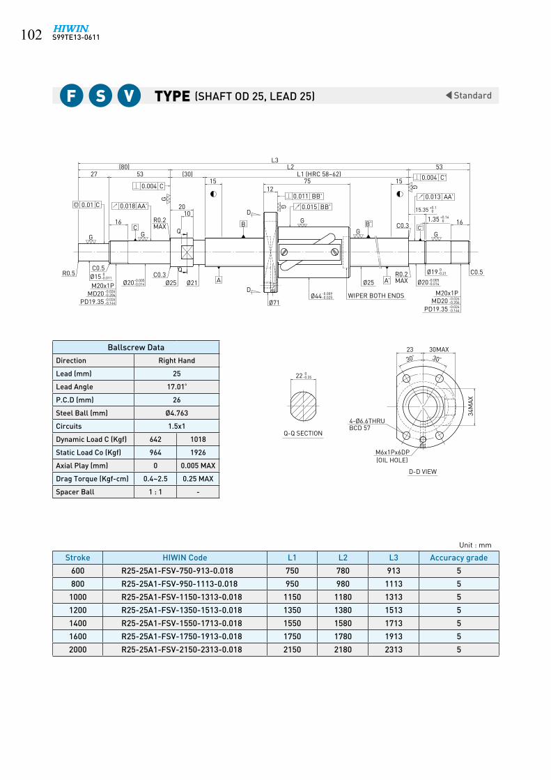
S99TE13-0611�0�
Type Standard
-0.005-0.014Ø20
0-0.011
22 0-0.35
A
16
Ø15
L2
10
C0.004
5327(80)
G G
G
G G
G15 15
C0.01 0.018 AA'
53L3
12
G
G
0.011 BB'
30° 30 °
23
34M
AX
30MAX
16
(30)
20
75
(OIL HOLE)M6x1Px6DP
D-D VIEW
Q-Q SECTIONBCD 574-Ø6.6THRU
WIPER BOTH ENDS
B B'
Q
C
Ø25C0.3
Ø21Ø25R0.5
M20x1P
C0.5
Ø71
D
D
M20x1P
C0.3 C'Q
C0.5
A'
R0.2MAX
15.35 +0.10
1.35 +0.140
Ø19 0-0.21
MD20PD19.35
-0.026-0.206-0.026-0.144
R0.2MAX
Ø44-0.009-0.025
Ø20-0.005-0.014
MD20PD19.35
-0.026-0.206-0.026-0.144
L1 (HRC 58~62)
0.015 BB'
0.004 C'
0.013 AA'
Stroke HIWIN Code L1 L2 L3 Accuracy grade
600 R25-25A1-FSV-750-913-0.018 750 780 913 5
800 R25-25A1-FSV-950-1113-0.018 950 980 1113 5
1000 R25-25A1-FSV-1150-1313-0.018 1150 1180 1313 5
1200 R25-25A1-FSV-1350-1513-0.018 1350 1380 1513 5
1400 R25-25A1-FSV-1550-1713-0.018 1550 1580 1713 5
1600 R25-25A1-FSV-1750-1913-0.018 1750 1780 1913 5
2000 R25-25A1-FSV-2150-2313-0.018 2150 2180 2313 5
Unit : mm
F S V (SHAFT OD 25, LEAD 25)
Ballscrew Data
Direction Right Hand
Lead (mm) 25
Lead Angle 17.01º
P.C.D (mm) 26
Steel Ball (mm) Ø4.763
Circuits 1.5x1
Dynamic Load C (Kgf) 642 1018
Static Load Co (Kgf) 964 1926
Axial Play (mm) 0 0.005 MAX
Drag Torque (Kgf-cm) 0.4~2.5 0.25 MAX
Spacer Ball 1 : 1 -

S99TE13-0611 �0�
Type Standard
-0.005-0.014
-0.005-0.014
30°BCD 67 30°
D-D VIEW
M6x1Px8DP(OIL HOLE)
Ø85
Q-Q SECTION
15100.004 C
PD24.026MD25M25x1.5P
Ø20
G
0.007 C
F0.4x0.2DIN509
X DETAIL
1.1
0.2
0.4
2
15°
8°
0.1
27
Ø27.5Ø25 Ø32C0.5Q
G
0.018 AA'
C20
XQ
G
12
AD Ø51
D
B
33 12(95)
62 (27)15
L3
G
0.013 AA'
9THRU4-
42M
AX
34MAX26
WIPER BOTH ENDSØ51
G
0.013 BB'
0.019 BB'
GØ32 A' Ø23.9
Ø25
G X
B' C'G
16.351.35
PD24.026
M25x1.5PMD25
20
0.004 C'
L2L1117 15
62
+0.10
+0.140
-0.032-0.268
-0.032-0.182
0-0.21
-0.010-0.029
-0.1-0.3
0-0.013
-0.032-0.268-0.032-0.182
+0.1 0+0.1 0
+0.050
0-0.35
Stroke HIWIN Code L1 L2 L3 Accuracy grade
1000 R32-25B1-FSV-1180-1376-0.018 1180 1219 1376 5
1500 R32-25B1-FSV-1680-1876-0.018 1680 1719 1876 5
2000 R32-25B1-FSV-2180-2376-0.018 2180 2219 2376 5
2600 R32-25B1-FSV-2780-2976-0.018 2780 2819 2976 5
Ballscrew Data
Direction Right Hand
Lead (mm) 25
Lead Angle 13.56º
P.C.D (mm) 33
Steel Ball (mm) Ø4.763
Circuits 2.5x1
Dynamic Load C (Kgf) 1140 1809
Static Load Co (Kgf) 2113 4226
Axial Play (mm) 0 0.005 or less
Drag Torque (Kgf-cm) 0.69~3.21 ~0.8
Spacer Ball 1 : 1 -
Unit : mm
(SHAFT OD 32, LEAD 25)F S V
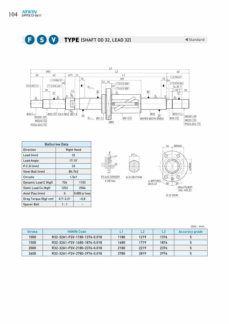
S99TE13-0611�0�
Type Standard
30°30°
0+0.116.35
-0.35 027
12
G
GG
G
G
62(95)L3
62
20
33
20
L2L1
G
(27) 1215 15
G
G
42M
AX
38MAX26
1512109
0+0.05
8°
20.1
15°
0.4
1.1
F0.4x0.2DIN509
X DETAIL 4-Ø9THRU
-0.182-0.032PD24.026
M6x1Px8DP
Ø32 -0.21 0Ø23.9
-0.014-0.005Ø25
-0.268-0.032MD25
M25X1.5P
-0.182-0.032PD24.026-0.268-0.032MD25
M25X1.5P-0.013 0Ø20 -0.014
-0.005Ø25 Ø27.5Ø32
-0.029-0.010Ø51-0.3
-0.1Ø51Ø85
C0.5
D
D
Q
Q
WIPER BOTH ENDS
0+0.141.35
X
Q-Q SECTION
BCD 67
(OIL HOLE)
C C'
0.004 C
0.018 AA'0.007 C
0.004 C'
0.018 AA'
B
A
B'
A'
0.013 BB'
0.019 BB'
X
D-D VIEW
+0.1 0
0.2
+0.1 0
0.2
Stroke HIWIN Code L1 L2 L3 Accuracy grade
1000 R32-32A1-FSV-1180-1376-0.018 1180 1219 1376 5
1500 R32-32A1-FSV-1680-1876-0.018 1680 1719 1876 5
2000 R32-32A1-FSV-2180-2376-0.018 2180 2219 2376 5
2600 R32-32A1-FSV-2780-2976-0.018 2780 2819 2976 5
Unit : mm
F S V (SHAFT OD 32, LEAD 32)
Ballscrew Data
Direction Right Hand
Lead (mm) 32
Lead Angle 17.15º
P.C.D (mm) 33
Steel Ball (mm) Ø4.763
Circuits 1.5x1
Dynamic Load C (Kgf) 726 1153
Static Load Co (Kgf) 1252 2504
Axial Play (mm) 0 0.005 or less
Drag Torque (Kgf-cm) 0.7~3.21 ~0.8
Spacer Ball 1 : 1 -

S99TE13-0611 �0�
Type Standard
45 °
-0.3
0.4
0.2
F0.4x0.2DIN509
X DETAIL
1.1 15
°
2
8°
0+0.050.1
M6x1Px8DP(OIL HOLE)
6-Ø9THRU,14x8.5DPBCD 90
MD25M25x1.5P
G
0Ø20-0.013
0.007 C
8+0.04+0.13 10
51(155) L2
INCOMPLETEG
-0.032
PD24.026 -0.182-0.032
-0.268
Ø25-0.009 0
AD
0.005 C
0.020 AA'
26C
104
X
3MAX
THREAD
D
15
G
(20)
Ø74Ø108
-0.029-0.010 -0.1Ø74
0.013 BB'
0.019 BB'
G
B G
15190±1.5
L1
L3
D-D VIEW
45°
41
104
0.005 C'
0.02 AA'
G
WIPER BOTH ENDS
Ø32 A' -0.00925 0
B'G X
C'
15
G
M25x1.5PMD25 -0.032
-0.268
PD24.026-0.182-0.032
2610
8 -0.04+0.13
+0.1 0+0.1 0
Stroke HIWIN Code L1 L2 L3 Accuracy grade
150 R32-10B2-FDW-380-575-0.018 380 400 575 5
250 R32-10B2-FDW-480-675-0.018 480 500 675 5
350 R32-10B2-FDW-580-775-0.018 580 600 775 5
450 R32-10B2-FDW-680-959-0.018 680 700 959 5
550 R32-10B2-FDW-780-1059-0.018 780 800 1059 5
750 R32-10B2-FDW-980-1259-0.018 980 1000 1259 5
950 R32-10B2-FDW-1180-1459-0.018 1180 1200 1459 5
1250 R32-10B2-FDW-1480-1759-0.018 1480 1500 1759 5
1550 R32-10B2-FDW-1780-2059-0.018 1780 1800 2059 5
Ballscrew Data
Direction Right Hand
Lead (mm) 10
Lead Angle 5.44º
P.C.D (mm) 33.4
Steel Ball (mm) Ø6.35
Circuits 2.5x2
Dynamic Load C (Kgf) 4810
Static Load Co (Kgf) 11199
Axial Play (mm) 0
Drag Torque (Kgf-cm) 5.51~11.43
Spacer Ball -
Unit : mm
(SHAFT OD 32, LEAD 10)F D W

S99TE13-0611�0�
Type Standard
45°45 °
X DETAIL
1/8PTx10DP(OIL HOLE)
6-Ø11THRU,Ø17.5x11DPBCD 98
0.007 C
M30x1.5P
10 12
61
INCOMPLETE
PD29.026-0.032-0.182
MD30 -0.268-0.032
AD
0.004 C
0.014 AA'
26C
X THREAD
3MAX
D
Ø120
0.012 BB'
0.015 BB'
B
18193±1.5
(165)104 (20) L1
L2L3
D-D VIEW
45
0.004 C'
0.014 AA'
WIPER BOTH ENDSA'
B'
XC'
20
M25x1.5P
-0.182-0.032PD24.026
MD25 -0.268-0.032
1226
104
F0.4x0.2DIN509
0.2
1.1 0.
4
15°
0.12
8°
+0.050
-0.013Ø25 0-0.009Ø30 0 Ø25 -0.009
0Ø36
Ø75-0.3-0.1Ø75-0.029
-0.010
0+0.1 0+0.1
G
GG
G
GG
GG
+0.13+0.04 10 +0.13
+0.04
Stroke HIWIN Code L1 L2 L3 Accuracy grade
250 R36-10B2-FDW-480-685-0.018 480 500 685 5
450 R36-10B2-FDW-680-885-0.018 680 700 885 5
750 R36-10B2-FDW-980-1269-0.018 980 1000 1269 5
1150 R36-10B2-FDW-1380-1669-0.018 1380 1400 1669 5
1550 R36-10B2-FDW-1780-2069-0.018 1780 1800 2069 5
Unit : mm
F D W (SHAFT OD 36, LEAD 10)
Ballscrew Data
Direction Right Hand
Lead (mm) 10
Lead Angle 4.86º
P.C.D (mm) 37.4
Steel Ball (mm) Ø6.35
Circuits 2.5x2
Dynamic Load C (Kgf) 5105
Static Load Co (Kgf) 12668
Axial Play (mm) 0
Drag Torque (Kgf-cm) 6.64~12.34
Spacer Ball -

S99TE13-0611 �0�
Type Standard
X DETAIL
6-Ø11THRU,Ø17.5x11DP 47
WIPER BOTH ENDSM30x1.5P
-0.268-0.032MD30
-0.182-0.032PD29.026
1/8PTx10DP
INCOMPLETE
D-0.009 0Ø30Ø40
-0.034-0.012Ø82 -0.3
-0.1Ø82Ø124
D
-0.009 0Ø30
-0.182-0.032PD29.026
M30x1.5P
-0.268-0.032MD30
-0.013 0Ø25
3MAX
THREADX
(OIL HOLE)
C C'
0.004 C
0.014 AA'0.007 C
0.004 C'
0.013 AA'
B
A
B'
A'
0.013 BB'
0.020 BB'
X
BCD 102
D-D VIEW
F0.4x0.2DIN509
1.1 0.
4
15°
0.12
8°
+0.050
10+0.13+0.04 12
61
26
(165)104 (20)
L3
18
L2
193±1.5L1
20
2612
104
10 +0.13+0.04
0.2
0+0.1
0.2
0+0.1
45 ° 45°
G G
G G
G
GG
G
Stroke HIWIN Code L1 L2 L3 Accuracy grade
250 R40-10B2-FDW-480-687-0.018 480 500 687 5
350 R40-10B2-FDW-580-787-0.018 580 600 787 5
450 R40-10B2-FDW-680-887-0.018 680 700 887 5
550 R40-10B2-FDW-780-1069-0.018 780 800 1069 5
750 R40-10B2-FDW-980-1269-0.018 980 1000 1269 5
950 R40-10B2-FDW-1180-1469-0.018 1180 1200 1469 5
1150 R40-10B2-FDW-1380-1669-0.018 1380 1400 1669 5
1350 R40-10B2-FDW-1580-1869-0.018 1580 1600 1869 5
1550 R40-10B2-FDW-1780-2069-0.018 1780 1800 2069 5
2150 R40-10B2-FDW-2380-2669-0.018 2380 2400 2669 5
Ballscrew Data
Direction Right Hand
Lead (mm) 10
Lead Angle 4.4º
P.C.D (mm) 41.4
Steel Ball (mm) Ø6.35
Circuits 2.5x2
Dynamic Load C (Kgf) 5369
Static Load Co (Kgf) 14138
Axial Play (mm) 0
Drag Torque (Kgf-cm) 8.26~13.78
Spacer Ball -
Unit : mm
(SHAFT OD 40, LEAD 10)F D W
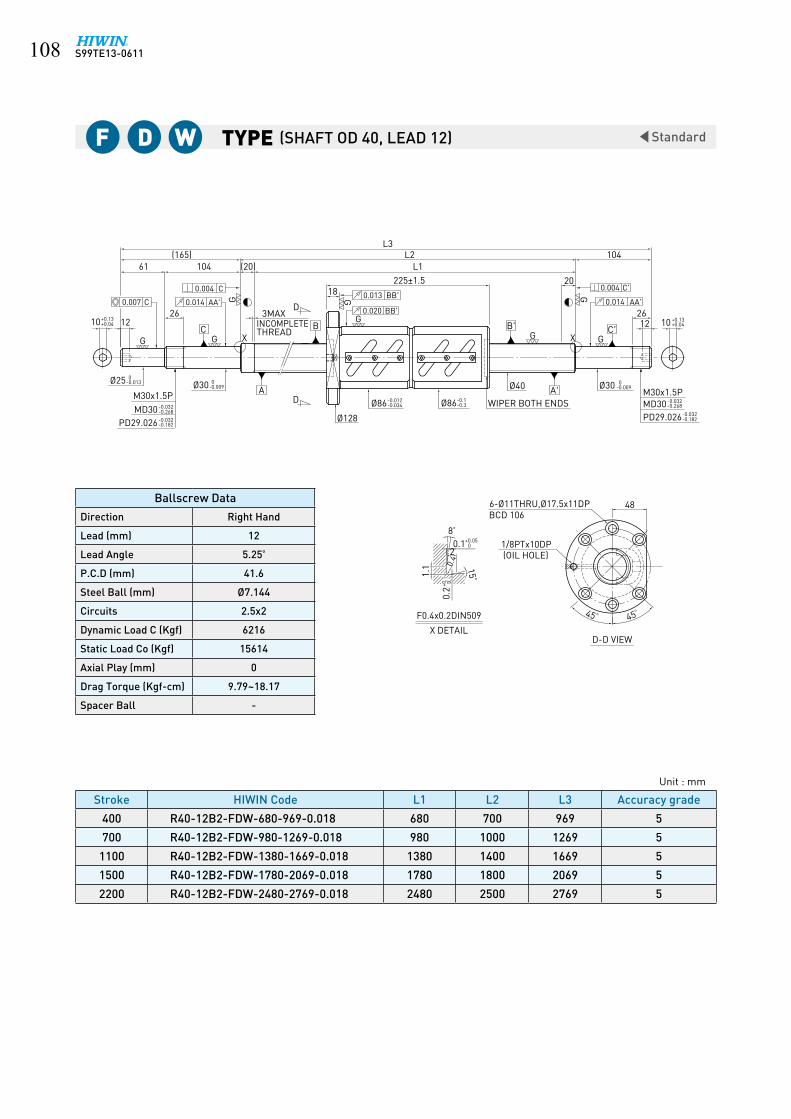
S99TE13-0611�0�
Type Standard
X DETAIL
12 +0.04+0.131012+0.04
+0.1310
G
GG
G
G
(165)L3
104
26
61104
26
L2L1
G
(20)
20
45 ° 45°
G
G
48
18225±1.5
-0.013 0Ø25
M30x1.5P-0.268-0.032MD30
-0.182-0.032PD29.026
M30x1.5P
-0.268-0.032MD30-0.182-0.032PD29.026
1/8PTx10DP
-0.009 0Ø30Ø40
WIPER BOTH ENDS
-0.009 0Ø30
D
INCOMPLETE
D
3MAX
THREADX
(OIL HOLE)
C C'
0.004 C
0.014 AA'0.007 C
0.004 C'
0.014 AA'
B
A
B'
A'
0.013 BB'
0.020 BB'
BCD 106
X
D-D VIEW
F0.4x0.2DIN509
1.1 0.
4
15°
0.12
8°
+0.050
-0.3-0.1Ø86-0.034
-0.012Ø86
Ø128
0.2
0+0.1
0.2
0+0.1
6-Ø11THRU,Ø17.5x11DP
Stroke HIWIN Code L1 L2 L3 Accuracy grade
400 R40-12B2-FDW-680-969-0.018 680 700 969 5
700 R40-12B2-FDW-980-1269-0.018 980 1000 1269 5
1100 R40-12B2-FDW-1380-1669-0.018 1380 1400 1669 5
1500 R40-12B2-FDW-1780-2069-0.018 1780 1800 2069 5
2200 R40-12B2-FDW-2480-2769-0.018 2480 2500 2769 5
Unit : mm
F D W (SHAFT OD 40, LEAD 12)
Ballscrew Data
Direction Right Hand
Lead (mm) 12
Lead Angle 5.25º
P.C.D (mm) 41.6
Steel Ball (mm) Ø7.144
Circuits 2.5x2
Dynamic Load C (Kgf) 6216
Static Load Co (Kgf) 15614
Axial Play (mm) 0
Drag Torque (Kgf-cm) 9.79~18.17
Spacer Ball -

S99TE13-0611 �0�
Type Standard
0-0.09
-0.004-0.012
-0.007-0.020
-0.003-0.011
+0.050
F0.4x0.2DIN509
X DETAIL
1.1
0.2
2
0.4
15°
0.1
8°
Q-Q SECTION
12
16
D-D VIEW
30°
29
30°
PD11.35
M12x1PØ12
MD12
Ø10 C0.5 Ø15Q
Ø14
0.003 C
0.010 AA'
G
0.005 C
10
15(45)
GC R0.2
MAX
G
Q
5 3
30 (15)10 5
WIPER BOTH ENDS
BCD 35
Ø44
AD
Ø16
4-Ø5.5THRU
Ø25
G
D
B
1010
L3
0.008 BB'0.010 BB'
G
G
L2L140
DP
Ø9.6
(OIL HOLE)M6x1Px6
Ø10
A' C0.5X
M5x0.8Px12DP
22
0.003 C'
0.007 AA'
B'
+0.109.15
C'G
G10
G
1.15 +0.140
0-0.009
-0.026-0.206
-0.026-0.144
+0.1 0+0.1 0
0-0.25
Stroke HIWIN Code L1 L2 L3 Accuracy grade
50 R16-2T4-FSI-139-221-0.008 139 154 221 3
100 R16-2T4-FSI-189-271-0.008 189 204 271 3
150 R16-2T4-FSI-239-321-0.008 239 254 321 3
200 R16-2T4-FSI-289-371-0.008 289 304 371 3
300 R16-2T4-FSI-389-471-0.008 389 404 471 3
Ballscrew Data
Direction Right Hand
Lead (mm) 2
Lead Angle 2.25º
P.C.D (mm) 16.2
Steel Ball (mm) Ø1.5
Circuits 1x4
Dynamic Load C (Kgf) 323
Static Load Co (Kgf) 790
Axial Play (mm) 0 0.005 or less
Drag Torque (Kgf-cm) 0.05~0.5 ~0.15
Spacer Ball 1 : 1 -
Unit : mm
(SHAFT OD 16, LEAD 2)F S I

S99TE13-0611��0
Type Standard
-0.007-0.020
D-D VIEW
X
BCD 35
0.01 BB'
0.008 BB'
A'
B'
A
B
0.012 AA'
0.004 C'
0.006 C 0.012 AA'
0.004 C
C'C
Q-Q SECTION
Ø10 Ø9.6 0-0.09
M5x0.8Px12DP
C0.2
MAXR0.2
D
D
M12x1PMD12
PD11.35Ø25
WIPER BOTH ENDS
Ø16Ø12 Ø15 Ø12
Ø44
1.15 +0.140
M6x1Px8DP4-Ø5.5THRU
Q
Q
X DETAIL
F0.4x0.2DIN509
0.2
1.1 0.
4 15°
0.12
8°
4410
G
G
1010
G
L122
15
10
3010 5
L3
G
G
G G
G
9.15 +0.10
29
30° 30°
16
5
L2(15)
(45)
-0.004-0.012
-0.003-0.011
+0.050
+0.1 0+0.1 0
Ø10 0-0.009
-0.026-0.206
-0.026-0.144
Stroke HIWIN Code L1 L2 L3 Accuracy grade
50 R16-2.5T4-FSI-139-221-0.008 139 154 221 3
100 R16-2.5T4-FSI-189-271-0.008 189 204 271 3
150 R16-2.5T4-FSI-239-321-0.008 239 254 321 3
200 R16-2.5T4-FSI-289-371-0.008 289 304 371 3
300 R16-2.5T4-FSI-389-471-0.008 389 404 471 3
Unit : mm
F S I (SHAFT OD 16, LEAD 2.5)
Ballscrew Data
Direction Right Hand
Lead (mm) 2.5
Lead Angle 2.81º
P.C.D (mm) 16.2
Steel Ball (mm) Ø1.5
Circuits 1x4
Dynamic Load C (Kgf) 323
Static Load Co (Kgf) 790
Axial Play (mm) 0 0.005 or less
Drag Torque (Kgf-cm) 0.05~0.5 ~0.15
Spacer Ball - -

S99TE13-0611 ���
StandardType
L2L3
L186
-0.35 022
(80)
G
53
16
27
G
1014
(30)15
G
G
12
G
45 ° 45°
31
0+0.115.35
53
G
(12)15
G
G
16C0.3 0+0.141.35
-0.206-0.026MD20
-0.144-0.026PD19.35
-0.21 0Ø19MAX
M6x1Px6DP
6-Ø6.6THRU,Ø11x6.5DP
WIPER BOTH ENDS
Ø28 Ø25 -0.014-0.005Ø20 M20x1PR0.2
D
Q
Q
C0.3
Ø85
DMAX
-0.144-0.026PD19.35-0.206-0.026MD20
Ø25-0.014-0.005Ø20 R0.2
M20x1P-0.011 0Ø15
-0.029-0.010Ø55
Q-Q SECTION
C'
0.016 AA'
(OIL HOLE)
C
0.005 C
0.016 AA'0.007 C
0.005 C'
B
A
B'
A'
0.015 BB'
0.019 BB'
BCD 69
D-D VIEW
Stroke HIWIN Code L1 L2 L3 Accuracy grade
150 R28-5B2-OFSW-270-399-0.018 270 300 399 5
250 R28-5B2-OFSW-370-499-0.018 370 400 499 5
350 R28-5B2-OFSW-470-599-0.018 470 500 599 5
450 R28-5B2-OFSW-558-733-0.018 558 600 733 5
650 R28-5B2-OFSW-758-933-0.018 758 800 933 5
850 R28-5B2-OFSW-958-1133-0.018 958 1000 1133 5
1050 R28-5B2-OFSW-1158-1333-0.018 1158 1200 1333 5
Ballscrew Data
Direction Right Hand
Lead (mm) 5
Lead Angle 3.19º
P.C.D (mm) 28.6
Steel Ball (mm) Ø3.175
Circuits 2.5x2
Dynamic Load C (Kgf) 1784
Static Load Co (Kgf) 4932
Axial Play (mm) 0
Drag Torque (Kgf-cm) 1.1~3.3
Spacer Ball -
Unit : mm
(SHAFT OD 16, LEAD 2)o F S W

S99TE13-0611���
StandardType
L2L3
L199
-0.35 022
14
(30)(80)
27 53
16
G G
G
10
15
G
12
G
45 ° 45°
31
0+0.115.35
53
G
1215
G
G
16
C0.3Ø25Ø28
0+0.141.35
-0.014-0.005Ø20
-0.144-0.026PD19.35
-0.206-0.026MD20
WIPER BOTH ENDS-0.21 0Ø19
M20x1P
D
Q
QØ25C0.3-0.014
-0.005Ø20-0.011 0Ø15
Ø85
D-0.206-0.026MD20
M20x1P
-0.144-0.026PD19.35
6-Ø6.6THRU,Ø11x6.5DP
M6x1Px6DP
-0.029-0.010Ø55
Q-Q SECTION
(OIL HOLE)
C C'
0.005 C
0.016 AA'0.007 C
0.005 C'
0.014 AA'
B
A
B'
A'
0.013 BB'
0.019 BB'
BCD 69
D-D VIEW
Stroke HIWIN Code L1 L2 L3 Accuracy grade
250 R28-6B2-OFSW-370-499-0.018 370 400 499 5
450 R28-6B2-OFSW-570-699-0.018 570 600 699 5
650 R28-6B2-OFSW-758-933-0.018 758 800 933 5
850 R28-6B2-OFSW-958-1133-0.018 958 1000 1133 5
1050 R28-6B2-OFSW-1158-1333-0.018 1158 1200 1333 5
Ballscrew Data
Direction Right Hand
Lead (mm) 6
Lead Angle 3.82º
P.C.D (mm) 28.6
Steel Ball (mm) Ø3.175
Circuits 2.5x2
Dynamic Load C (Kgf) 1784
Static Load Co (Kgf) 4932
Axial Play (mm) 0
Drag Torque (Kgf-cm) 1.2~3.6
Spacer Ball -
Unit : mm
(SHAFT OD 28, LEAD 6)o F S W

S99TE13-0611 ���
StandardType
X DETAIL
6-Ø6.6THRU,Ø11x6.5DP
D
-0.009 0Ø25Ø32-0.009
0Ø25-0.013 0Ø20
-0.029-0.010Ø58 WIPER BOTH ENDS
Ø85
D
INCOMPLETE
-0.182-0.032PD24.026
-0.268-0.032MD25
M25x1.5P
-0.182-0.032PD24.026-0.268-0.032MD25
M25x1.5P
M6x1Px6DP
2MAX
THREAD
(OIL HOLE)
C C'
0.004 C0.014 AA'0.006 C
0.004 C'
0.014 AA'
B
A
B'
A'
0.012 BB'0.015 BB'
BCD 71
D-D VIEW
F0.4X0.2DIN509
0.2
1.1 0.
4
15°
0.12
8°
+0.050
G
G
G
G
G
G G
G
X X
8+0.13+0.04 10
26
51(140)
1589 (20)
8612
L3L2
L115
32
1026
89
8+0.13+0.04
0+0.1 0+0.1
45 ° 45°
Stroke HIWIN Code L1 L2 L3 Accuracy grade
150 R32-5B2-OFSW-280-460-0.018 280 300 460 5
250 R32-5B2-OFSW-380-560-0.018 380 400 560 5
350 R32-5B2-OFSW-480-660-0.018 480 500 660 5
450 R32-5B2-OFSW-580-760-0.018 580 600 760 5
550 R32-5B2-OFSW-680-929-0.018 680 700 929 5
650 R32-5B2-OFSW-780-1029-0.018 780 800 1029 5
850 R32-5B2-OFSW-980-1229-0.018 980 1000 1229 5
1050 R32-5B2-OFSW-1180-1429-0.018 1180 1200 1429 5
1350 R32-5B2-OFSW-1480-1729-0.018 1480 1500 1729 5
Ballscrew Data
Direction Right Hand
Lead (mm) 5
Lead Angle 2.79º
P.C.D (mm) 32.6
Steel Ball (mm) Ø3.175
Circuits 2.5x2
Dynamic Load C (Kgf) 1886
Static Load Co (Kgf) 5666
Axial Play (mm) 0
Drag Torque (Kgf-cm) 1.2~3.6
Spacer Ball -
Unit : mm
(SHAFT OD 32, LEAD 5)o F S W

S99TE13-0611���
StandardType
Stroke HIWIN Code L1 L2 L3 Accuracy grade
250 R32-6B2-OFSW-380-560-0.018 380 400 560 5
450 R32-6B2-OFSW-580-760-0.018 580 600 760 5
650 R32-6B2-OFSW-780-1029-0.018 780 800 1029 5
850 R32-6B2-OFSW-980-1229-0.018 980 1000 1229 5
1050 R32-6B2-OFSW-1180-1429-0.018 1180 1200 1429 5
1350 R32-6B2-OFSW-1480-1729-0.018 1480 1500 1729 5
Ballscrew Data
Direction Right Hand
Lead (mm) 6
Lead Angle 3.33º
P.C.D (mm) 32.8
Steel Ball (mm) Ø3.969
Circuits 2.5x2
Dynamic Load C (Kgf) 2556
Static Load Co (Kgf) 7019
Axial Play (mm) 0
Drag Torque (Kgf-cm) 2.32~4.82
Spacer Ball -
Unit : mm
(SHAFT OD 32, LEAD 6)o F S W
X DETAIL
34
WIPER BOTH ENDS
6-Ø6.6THRU,Ø11x6.5DP
M6x1Px6DP
-0.029-0.010Ø62
Ø89
Ø32 -0.009 0Ø25-0.009
0Ø25-0.013 0Ø20
-0.182-0.032PD24.026-0.268-0.032MD25
M25x1.5P
-0.182-0.032PD24.026
-0.268-0.032MD25
M25x1.5P
INCOMPLETE
D
D
2MAX
THREADX
(OIL HOLE)
BCD 75
C C'
0.005 C
0.017 AA'0.007 C
0.005 C'
0.017 AA'
B
A
B'
A'
0.013 BB'
0.019 BB'
X
D-D VIEW
F0.4x0.2DIN509
0.2
1.1 0.
4 15°
0.12
8°
+0.050
G
G
G
G
G G
G
G
(140)
8+0.13+0.04 10
26
51 L189 (20)15
12
L3
99
L2
26
15
89
10+0.13+0.048
0+0.1 0+0.1
45 ° 45°

S99TE13-0611 ���
StandardType
Stroke HIWIN Code L1 L2 L3 Accuracy grade
250 R32-8B1-OFSW-380-560-0.018 380 400 560 5
450 R32-8B1-OFSW-580-760-0.018 580 600 760 5
650 R32-8B1-OFSW-780-1029-0.018 780 800 1029 5
850 R32-8B1-OFSW-980-1229-0.018 980 1000 1229 5
1350 R32-8B1-OFSW-1480-1729-0.018 1480 1500 1729 5
1350 R32-6B2-OFSW-1480-1729-0.018 1480 1500 1729 5
Ballscrew Data
Direction Right Hand
Lead (mm) 8
Lead Angle 4.41º
P.C.D (mm) 33
Steel Ball (mm) Ø4.763
Circuits 2.5x1
Dynamic Load C (Kgf) 2650
Static Load Co (Kgf) 5599
Axial Play (mm) 0
Drag Torque (Kgf-cm) 1.26~5.06
Spacer Ball -
Unit : mm
(SHAFT OD 32, LEAD 8)o F S W
10 +0.04+0.13810+0.04
+0.148
G
GG
G
G
(140)L3
89
26
5189
26
L2L1
G
(20)15 15
45 ° 45°
G
G
38
1582
0+0.05
8°
20.1
15°
0.4
1.1
0.2
F0.4x0.2DIN509X DETAIL
6-Ø9THRU,Ø14x8.5DP
M6x1Px8DP(OIL HOLE)
-0.029-0.010Ø66 WIPER BOTH ENDS
Ø100
-0.009 0Ø25Ø32-0.009
0Ø25-0.013 0Ø20
-0.182-0.032PD24.026-0.268-0.032MD25
M25x1.5P
-0.182-0.032PD24.026
-0.268-0.032MD25
M25x1.5P
INCOMPLETE
D
D
2MAX
THREADC C'
0.005 C
0.017 AA'0.007 C
0.005 C'
0.017 AA'
B
A
B'
A'
0.013 BB'
0.019 BB'
BCD 82
X
D-D VIEW
+0.1 0+0.1 0

S99TE13-0611���
StandardType
10-0.04+0.138
10+0.04+0.138
G
GG
G
G
(140)L3
89
26
5189
26
L2L1
G
(20)
15 15
45 ° 45°
G
G
41
15100
0+0.05
8°
20.1
15°
0.4
1.1
0.2
F0.4x0.2DIN509
X DETAIL
6-Ø9THRU,Ø14x8.5DP
-0.029-0.010Ø74 WIPER BOTH ENDS
Ø32 -0.009 0Ø25-0.009
0Ø25D
D
-0.182-0.032PD24.026-0.268-0.032MD25
M25x1.5P
M6x1Px8DP
-0.013 0Ø20
INCOMPLETE
Ø108-0.268-0.032MD25
M25x1.5P
-0.182-0.032PD24.026
3MAX
THREAD
(OIL HOLE)
C C'
0.005 C
0.020 AA'0.007 C
0.005 C'
0.017 AA'
B
A
B'
A'
0.013 BB'
0.019 BB'
BCD 90
D-D VIEW
X X
+0.1 0+0.1 0
Stroke HIWIN Code L1 L2 L3 Accuracy grade
250 R32-10B1-OFSW-380-560-0.018 380 400 560 5
350 R32-10B1-OFSW-480-660-0.018 480 500 660 5
450 R32-10B1-OFSW-580-760-0.018 580 600 760 5
550 R32-10B1-OFSW-680-929-0.018 680 700 929 5
650 R32-10B1-OFSW-780-1029-0.018 780 800 1029 5
850 R32-10B1-OFSW-980-1229-0.018 980 1000 1229 5
1050 R32-10B1-OFSW-1180-1429-0.018 1180 1200 1429 5
1350 R32-10B1-OFSW-1480-1729-0.018 1480 1500 1729 5
1650 R32-10B1-OFSW-1780-2029-0.018 1780 1800 2029 5
Ballscrew Data
Direction Right Hand
Lead (mm) 10
Lead Angle 5.44º
P.C.D (mm) 33.4
Steel Ball (mm) Ø6.35
Circuits 2.5x1
Dynamic Load C (Kgf) 2650
Static Load Co (Kgf) 5599
Axial Play (mm) 0
Drag Torque (Kgf-cm) 3.58~7.44
Spacer Ball -
Unit : mm
(SHAFT OD 32, LEAD 10)o F S W

S99TE13-0611 ���
StandardType
G
12 +0.04+0.131012+0.04
+0.1310
G
GG G
(150)L3
89
26
6189
26
L2L1
G
(20)20
45 ° 45°
G
G
45
18103
0+0.05
8°
20.1
15°
0.4
1.1
0.2
F0.4x0.2DIN509X DETAIL
6-Ø11THRU,Ø17.5x11DP
1/8PTx10DP
-0.009 0Ø25
-0.182-0.032PD24.026
-0.268-0.032MD25
M25x1.5PØ36
-0.029-0.010Ø75 WIPER BOTH ENDS
Ø120
-0.009 0Ø30-0.013
0Ø25
-0.182-0.032PD29.026-0.268-0.032MD30
M30x1.5P
X X
D
D
INCOMPLETE3MAX
THREADC
BCD 98
(OIL HOLE)
C
0.005 C
0.02 AA'0.009 C
0.005 C'
0.020 AA'
B
A
B'
A'
0.013 BB'
0.019 BB'
D-D VIEW
+0.1 0+0.1 0
Stroke HIWIN Code L1 L2 L3 Accuracy grade
350 R36-10B1-OFSW-480-670-0.018 480 500 670 5
550 R36-10B1-OFSW-680-870-0.018 680 700 870 5
850 R36-10B1-OFSW-980-1239-0.018 980 1000 1239 5
1250 R36-10B1-OFSW-1380-1639-0.018 1380 1400 1639 5
1650 R36-10B1-OFSW-1780-2039-0.018 1780 1800 2039 5
Ballscrew Data
Direction Right Hand
Lead (mm) 10
Lead Angle 4.84º
P.C.D (mm) 37.4
Steel Ball (mm) Ø6.35
Circuits 2.5x1
Dynamic Load C (Kgf) 2812
Static Load Co (Kgf) 6334
Axial Play (mm) 0
Drag Torque (Kgf-cm) 3.91~8.13
Spacer Ball -
Unit : mm
(SHAFT OD 36, LEAD 10)o F S W

S99TE13-0611���
StandardType
12 +0.04+0.131012+0.04
+0.1310
G
GG
G
G
(150)L3
89
26
6189
26
L2L1
G
(20)20
45 ° 45°
G
G
39
1589
0+0.05
8°
20.1
15°
0.4
1.1
0.2
F0.4x0.2DIN509X DETAIL
6-Ø9THRU,Ø14x8.5DP
M30x1.5P-0.268-0.032MD30
-0.182-0.032PD29.026
M30x1.5P-0.268-0.032MD30-0.182-0.032PD29.026
-0.009 0Ø30
-0.029-0.010Ø67 WIPER BOTH ENDS
Ø101
Ø40-0.013 0Ø25 -0.009
0Ø30
1/8PTx10DP
2MAX
THREAD
(OIL HOLE)
D
D
INCOMPLETEX
C C'
0.005 C
0.018 AA'0.009 C
0.005 C'
0.018 AA'
B
A
B'
A'
0.013 BB'
0.019 BB'
BCD 83
X
D-D VIEW
+0.1 0+0.1 0
Stroke HIWIN Code L1 L2 L3 Accuracy grade
250 R40-5B2-OFSW-380-572-0.018 380 400 572 5
450 R40-5B2-OFSW-580-772-0.018 580 600 772 5
650 R40-5B2-OFSW-780-1039-0.018 780 800 1039 5
850 R40-5B2-OFSW-980-1239-0.018 980 1000 1239 5
1050 R40-5B2-OFSW-1180-1439-0.018 1180 1200 1439 5
1450 R40-5B2-OFSW-1580-1839-0.018 1580 1600 1839 5
Ballscrew Data
Direction Right Hand
Lead (mm) 5
Lead Angle 2.24º
P.C.D (mm) 40.6
Steel Ball (mm) Ø3.175
Circuits 2.5x2
Dynamic Load C (Kgf) 2070
Static Load Co (Kgf) 7134
Axial Play (mm) 0
Drag Torque (Kgf-cm) 1.81~4.21
Spacer Ball -
Unit : mm
(SHAFT OD 40, LEAD 5)o F S W

S99TE13-0611 ���
StandardType
12 +0.04+0.131012+0.04
+0.1310
G
GG
G
G
(150)L3
89
26
6189
26
L2L1
G
(20)20
45° 45°
G
G
41
15130
0+0.05
8°
20.1
15°
0.4
1.1
0.2
F0.4x0.2DIN509X DETAIL
4-Ø9THRU,Ø14x8.5DP
M30x1.5P-0.268-0.032MD30
-0.182-0.032PD29.026
M30x1.5P-0.268-0.032MD30-0.182-0.032PD29.026
Ø40 -0.009 0Ø30-0.009
0Ø30
D
D
INCOMPLETE
-0.013 0Ø25
-0.029-0.010Ø74 WIPER BOTH ENDS
Ø108
1/8PTx10DP
THREAD
2MAX
(OIL HOLE)
XC C'
0.005 C
0.018 AA'0.009 C
0.005 C'
0.018 AA'
B
A
B'
A'
0.015 BB'
0.019 BB'
BCD 90
X
D-D VIEW
+0.1 0+0.1 0
Stroke HIWIN Code L1 L2 L3 Accuracy grade
200 R40-8B2-OFSW-380-572-0.018 380 400 572 5
400 R40-8B2-OFSW-580-772-0.018 580 600 772 5
600 R40-8B2-OFSW-780-1039-0.018 780 800 1039 5
800 R40-8B2-OFSW-980-1239-0.018 980 1000 1239 5
1000 R40-8B2-OFSW-1180-1439-0.018 1180 1200 1439 5
1400 R40-8B2-OFSW-1580-1839-0.018 1580 1600 1839 5
Ballscrew Data
Direction Right Hand
Lead (mm) 8
Lead Angle 3.55º
P.C.D (mm) 41
Steel Ball (mm) Ø4.763
Circuits 2.5x2
Dynamic Load C (Kgf) 3634
Static Load Co (Kgf) 10603
Axial Play (mm) 0
Drag Torque (Kgf-cm) 4.24~8.82
Spacer Ball -
Unit : mm
(SHAFT OD 40, LEAD 8)o F S W

S99TE13-0611��0
StandardType
12 +0.04+0.131012+0.04
+0.1310
G
GG
G
G
(150)L3
89
26
6189
26
L2L1
G
(20)20
45 ° 45°
G
G
47
18103
0+0.05
8°
20.1
15°
0.4
1.1
0.2
F0.4x0.2DIN509X DETAIL
6-Ø11THRU,Ø17.5x11DP
WIPER BOTH ENDSM30x1.5P
-0.268-0.032MD30
-0.182-0.032PD29.026
1/8PTx10DP
INCOMPLETE
D
-0.009 0Ø30Ø40
-0.034-0.012Ø82
Ø124
D
-0.009 0Ø30
-0.182-0.032PD29.026
M30x1.5P-0.268-0.032MD30
-0.013 0Ø25
3MAX
THREADX
(OIL HOLE)
C C'
0.004 C
0.014 AA'0.007 C
0.004 C'
0.014 AA'
B
A
B'
A'
0.013 BB'
0.020 BB'
X
BCD 102
D-D VIEW
+0.1 0+0.1 0
Stroke HIWIN Code L1 L2 L3 Accuracy grade
350 R40-10B1-OFSW-480-672-0.018 480 500 672 5
450 R40-10B1-OFSW-580-772-0.018 580 600 772 5
550 R40-10B1-OFSW-680-872-0.018 680 700 872 5
650 R40-10B1-OFSW-780-1039-0.018 780 800 1039 5
850 R40-10B1-OFSW-980-1239-0.018 980 1000 1239 5
1050 R40-10B1-OFSW-1180-1439-0.018 1180 1200 1439 5
1250 R40-10B1-OFSW-1380-1639-0.018 1380 1400 1639 5
1450 R40-10B1-OFSW-1580-1839-0.018 1580 1600 1839 5
1650 R40-10B1-OFSW-1780-2039-0.018 1780 1800 2039 5
2250 R40-10B1-OFSW-2380-2639-0.018 2380 2400 2639 5
Ballscrew Data
Direction Right Hand
Lead (mm) 10
Lead Angle 4.4º
P.C.D (mm) 41.4
Steel Ball (mm) Ø6.35
Circuits 2.5x1
Dynamic Load C (Kgf) 2958
Static Load Co (Kgf) 7069
Axial Play (mm) 0
Drag Torque (Kgf-cm) 4.57~8.49
Spacer Ball -
Unit : mm
(SHAFT OD 40, LEAD 10)o F S W
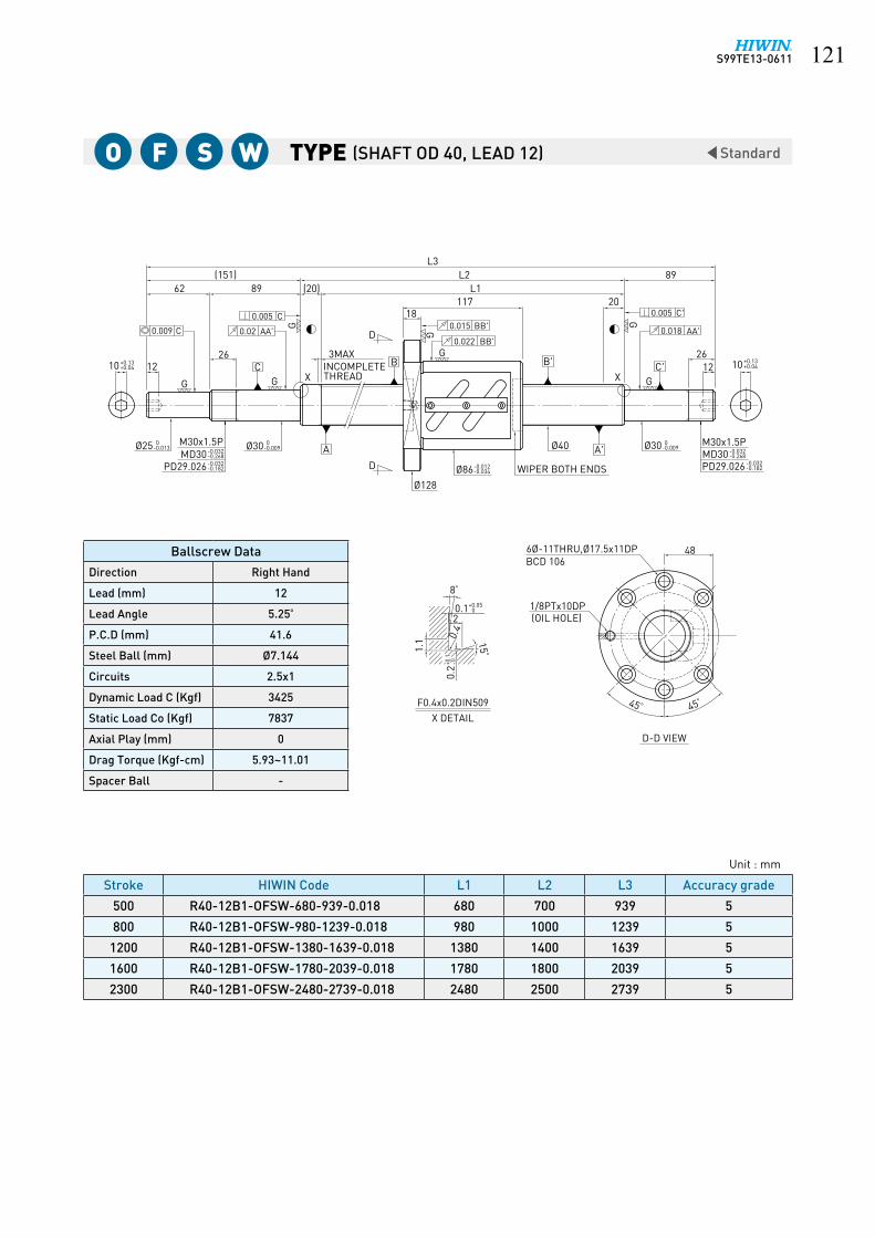
S99TE13-0611 ���
StandardType
12+0.04+0.1310 12 +0.04
+0.1310
G
GG
G
G
(151)L3
89
26
6289
26
L2L1(20)
20
45 ° 45°
G
G
48
18117
0+0.05
8°
20.1
15°
0.4
1.1
0.2
F0.4x0.2DIN509X DETAIL
6Ø-11THRU,Ø17.5x11DP
M30x1.5P-0.268-0.032MD30
-0.182-0.032PD29.026
M30x1.5P-0.268-0.032MD30-0.182-0.032PD29.026
1/8PTx10DP
-0.009 0Ø30Ø40
-0.034-0.012Ø86 WIPER BOTH ENDS
Ø128
INCOMPLETE
-0.009 0Ø30-0.013
0Ø25
D
D
3MAX
THREAD X
(OIL HOLE)
C C'
0.005 C
0.02 AA'0.009 C
0.005 C'
0.018 AA'
B
A
B'
A'
0.015 BB'
0.022 BB'
BCD 106
X
D-D VIEW
+0.1 0+0.1 0
Stroke HIWIN Code L1 L2 L3 Accuracy grade
500 R40-12B1-OFSW-680-939-0.018 680 700 939 5
800 R40-12B1-OFSW-980-1239-0.018 980 1000 1239 5
1200 R40-12B1-OFSW-1380-1639-0.018 1380 1400 1639 5
1600 R40-12B1-OFSW-1780-2039-0.018 1780 1800 2039 5
2300 R40-12B1-OFSW-2480-2739-0.018 2480 2500 2739 5
Ballscrew Data
Direction Right Hand
Lead (mm) 12
Lead Angle 5.25º
P.C.D (mm) 41.6
Steel Ball (mm) Ø7.144
Circuits 2.5x1
Dynamic Load C (Kgf) 3425
Static Load Co (Kgf) 7837
Axial Play (mm) 0
Drag Torque (Kgf-cm) 5.93~11.01
Spacer Ball -
Unit : mm
(SHAFT OD 40, LEAD 12)o F S W

S99TE13-0611���
StandardType
+0.05+0.23121414+0.05
+0.2312
G
GG
G
G
(155)L3
92
30
6392
30
L2L1
G
(20)20
45 ° 45°
G
G
50
18103
0+0.05
8°
20.1
15°
0.4
1.1
0.2
F0.4x0.2DIN509X DETAIL
6-Ø11THRU,Ø17.5x11DP
M35x1.5P-0.268-0.032MD35
-0.182-0.032PD34.026
1/8PTx10DP(OIL HOLE)
Ø45 -0.011 0Ø35
Ø132-0.034-0.012Ø88 WIPER BOTH ENDS
-0.011 0Ø35-0.013
0Ø30
-0.182-0.032PD34.026-0.268-0.032MD35
M35x1.5P
D
D
INCOMPLETE3MAX
THREADXC C'
0.005 C
0.020 AA'0.009 C
0.005 C'
0.018 AA'
B
A
B'
A'
0.015 BB'
0.022 BB'
BCD 110
X
D-D VIEW
+0.1 0+0.1 0
Stroke HIWIN Code L1 L2 L3 Accuracy grade
550 R45-10B1-OFSW-680-947-0.018 680 700 947 5
850 R45-10B1-OFSW-980-1247-0.018 980 1000 1247 5
1250 R45-10B1-OFSW-1380-1647-0.018 1380 1400 1647 5
1650 R45-10B1-OFSW-1780-2047-0.018 1780 1800 2047 5
2350 R45-10B1-OFSW-2480-2747-0.018 2480 2500 2747 5
Ballscrew Data
Direction Right Hand
Lead (mm) 10
Lead Angle 3.92º
P.C.D (mm) 46.4
Steel Ball (mm) Ø6.35
Circuits 2.5x1
Dynamic Load C (Kgf) 3115
Static Load Co (Kgf) 7952
Axial Play (mm) 0
Drag Torque (Kgf-cm) 4.58~9.5
Spacer Ball -
Unit : mm
(SHAFT OD 45, LEAD 10)o F S W

S99TE13-0611 ���
StandardType
+0.05+0.23141616+0.05
+0.2314
G
GG
G
G
(170)L3
92
30
7892
30
L2L1
G
(20)20
45 ° 45°
G
G
51
18103
0+0.05
8°
20.1
15°
0.4
+0.1 0
1.1
0.2
F0.4x0.2DIN509
X DETAIL
6-Ø11THRU,Ø17.5x11DP
M40x1.5P-0.268-0.032MD40
-0.182-0.032PD39.026
1/8PTx10DP(OIL HOLE)
Ø50 -0.011 0Ø40
Ø135-0.034-0.012Ø93 WIPER BOTH ENDS
-0.011 0Ø40-0.016
0Ø35
-0.182-0.032PD39.026-0.268-0.032MD40
M40x1.5P
D
D
INCOMPLETETHREAD
3MAX
XC C'
0.005 C
0.020 AA'0.009 C
0.005 C'
0.018 AA'
B
A
B'
A'
0.015 BB'
0.022 BB'
BCD 113
X
D-D VIEW
+0.1 0
Stroke HIWIN Code L1 L2 L3 Accuracy grade
450 R50-10B1-OFSW-580-862-0.018 580 600 862 5
650 R50-10B1-OFSW-780-1062-0.018 780 800 1062 5
850 R50-10B1-OFSW-980-1262-0.018 980 1000 1262 5
1050 R50-10B1-OFSW-1180-1462-0.018 1180 1200 1462 5
1350 R50-10B1-OFSW-1480-1762-0.018 1480 1500 1762 5
1850 R50-10B1-OFSW-1980-2262-0.018 1980 2000 2262 5
2450 R50-10B1-OFSW-2580-2862-0.018 2580 2600 2862 5
Ballscrew Data
Direction Right Hand
Lead (mm) 10
Lead Angle 3.54º
P.C.D (mm) 51.4
Steel Ball (mm) Ø6.35
Circuits 2.5x1
Dynamic Load C (Kgf) 3263
Static Load Co (Kgf) 8835
Axial Play (mm) 0
Drag Torque (Kgf-cm) 4.84~11.28
Spacer Ball -
Unit : mm
(SHAFT OD 50, LEAD 10)o F S W

S99TE13-0611���
StandardType
0+0.05
8°
20.1
15°
0.4
1.1
0.2
F0.4x0.2DIN509X DETAIL
+0.05+0.23141616+0.05
+0.2314
G
GG
G
G
(185)L3
107
30
78107
30
L2L1
G
(20)20
45 ° 45°
G
G
51
18163
6-Ø11THRU,Ø17.5x11DP
M40x1.5P-0.268-0.032MD40
-0.182-0.032PD39.026
1/8PTx10DP(OIL HOLE)
Ø50 -0.011 0Ø40
Ø135-0.034-0.012Ø93 WIPER BOTH ENDS
-0.011 0Ø40-0.016
0Ø35
-0.182-0.032PD39.026-0.268-0.032MD40
M40x1.5P
D
D
INCOMPLETETHREAD
3MAX
XC C'
0.005 C
0.020 AA'0.009 C
0.005 C'
0.018 AA'
B
A
B'
A'
0.015 BB'
0.022 BB'
BCD 113
X
D-D VIEW
+0.1 0+0.1 0
Stroke HIWIN Code L1 L2 L3 Accuracy grade
350 R50-10B2-OFSW-580-892-0.018 580 600 892 5
550 R50-10B2-OFSW-780-1092-0.018 780 800 1092 5
750 R50-10B2-OFSW-980-1292-0.018 980 1000 1292 5
950 R50-10B2-OFSW-1180-1492-0.018 1180 1200 1492 5
1250 R50-10B2-OFSW-1480-1792-0.018 1480 1500 1792 5
1750 R50-10B2-OFSW-1980-2292-0.018 1980 2000 2292 5
2350 R50-10B2-OFSW-2580-2892-0.018 2580 2600 2892 5
Ballscrew Data
Direction Right Hand
Lead (mm) 10
Lead Angle 3.54º
P.C.D (mm) 51.4
Steel Ball (mm) Ø6.35
Circuits 2.5x2
Dynamic Load C (Kgf) 5923
Static Load Co (Kgf) 17670
Axial Play (mm) 0
Drag Torque (Kgf-cm) 10.48~17.48
Spacer Ball -
Unit : mm
(SHAFT OD 50, LEAD 10)o F S W

S99TE13-0611 ���
Type High Lead
G G
G
G
G
GG
G
10
10
15
(45)
(15)30
5
10 5
L3
24
5
L1
10
L2
1.15 +0.14 0
9.15 +0.1 0
10
22
D-D VIEW
BCD 45
0.015 BB'
0.011 BB'
A'
B'
A
B
0.016 AA'
0.004 C'0.007 C
0.016 AA'
0.004 C
C'C
D
D
OIL HOLE
MAX
Q-Q SECTION
44
Ø15 Ø12M12x1PØ12 -0.003
-0.011Ø10 0-0.009
MD12 -0.026-0.206
PD11.35 -0.026-0.144
R0.2
C0.5
MAX
Ø57
WITHOUT WIPER
M6x1Px6DP
50
34
4-Ø5.5THRU,Ø9.5x5.5DP
30°30°
R0.2C0.2
Q
Q
Ø15
Ø34-0.009-0.025Ø34-0.1
-0.3
Ø9.6 0-0.09
-0.004-0.012Ø10
12 0-0.25
6.5 High Lead Ground Ballscrew
Stroke HIWIN Code L1 L2 L3 Accuracy grade
150 R15-10U2-DFSH-239-321-0.018 239 254 321 5
200 R15-10U2-DFSH-289-371-0.018 289 304 371 5
250 R15-10U2-DFSH-339-421-0.018 339 354 421 5
300 R15-10U2-DFSH-389-471-0.018 389 404 471 5
350 R15-10U2-DFSH-439-521-0.018 439 454 521 5
400 R15-10U2-DFSH-489-571-0.018 489 504 571 5
450 R15-10U2-DFSH-539-621-0.018 539 554 621 5
500 R15-10U2-DFSH-589-671-0.018 589 604 671 5
550 R15-10U2-DFSH-639-721-0.018 639 654 721 5
600 R15-10U2-DFSH-689-771-0.018 689 704 771 5
700 R15-10U2-DFSH-789-871-0.018 789 804 871 5
800 R15-10U2-DFSH-889-971-0.018 889 904 971 5
Unit : mm
F S H (SHAFT OD 15, LEAD 10)
Ballscrew Data
Direction Right Hand
Lead (mm) 10
Lead Angle 11.53º
P.C.D (mm) 15.6
Steel Ball (mm) Ø3.175
Circuits 2.8x2
Dynamic Load C (Kgf) 776 1231
Static Load Co (Kgf) 1244 2487
Axial Play (mm) 0 0.005 or less
Drag Torque (Kgf-cm) 0.2~1 -
Spacer Ball 1 : 1 -

S99TE13-0611���
High LeadType
D-D VIEW
BCD 45
0.015 BB'
0.011 BB'
A'
B'
A
B
0.016 AA'
0.004 C'0.007 C
0.016 AA'
0.004 C
C'C
D
D
OIL HOLE
MAX
Q-Q SECTION
45
Ø15 Ø12M12x1PØ12-0.003
-0.011Ø10 0-0.009
MD12 -0.026-0.206
PD11.35 -0.026-0.144
R0.2
C0.5
MAX
Ø57
Ø9.6 0-0.09
Ø10 -0.004-0.012
WITHOUT WIPER
M6x1Px6DP4-Ø5.5THRU,Ø9.5x5.5DP
R0.2C0.2
Q
Q
Ø15
Ø34-0.009-0.025Ø34-0.1
-0.3
2410
5
G
G
1010
G
L122
15
10
30
10 8
L3(45)
G
G
G G
G
9.15 +0.1 0
1.15 +0.14 0
(18)L2
5
30° 30°
34
50
12 0-0.25
Stroke HIWIN Code L1 L2 L3 Accuracy grade
150 R15-20A2-DFSH-236-321-0.018 236 254 321 5
200 R15-20A2-DFSH-286-371-0.018 286 304 371 5
250 R15-20A2-DFSH-336-421-0.018 336 354 421 5
300 R15-20A2-DFSH-386-471-0.018 386 404 471 5
350 R15-20A2-DFSH-436-521-0.018 436 454 521 5
400 R15-20A2-DFSH-486-571-0.018 486 504 571 5
450 R15-20A2-DFSH-536-621-0.018 536 554 621 5
500 R15-20A2-DFSH-586-671-0.018 586 604 671 5
550 R15-20A2-DFSH-636-721-0.018 636 654 721 5
600 R15-20A2-DFSH-686-771-0.018 686 704 771 5
700 R15-20A2-DFSH-786-871-0.018 786 804 871 5
800 R15-20A2-DFSH-886-971-0.018 886 904 971 5
Unit : mm
D F S H (SHAFT OD 15, LEAD 20)
Ballscrew Data
Direction Right Hand
Lead (mm) 20
Lead Angle 22.2º
P.C.D (mm) 15.6
Steel Ball (mm) Ø3.175
Circuits 1.8x2
Dynamic Load C (Kgf) 520 825
Static Load Co (Kgf) 781 1562
Axial Play (mm) 0 0.005 or less
Drag Torque (Kgf-cm) 0.2~0.9 -
Spacer Ball 1 : 1 -

S99TE13-0611 ���
Type High Lead
-0.25 012
50
36
30°30°
5
L2(18)
0+0.141.15
0+0.19.15
G
GG
G
G G
(45)L3
81030
10
1522
L1
G
10 10
G
G
5
10 24
45
OIL HOLE
4-Ø5.5THRU
D-D VIEW
Q-Q SECTIONX DETAIL
WITHOUT WIPER
0+0.05
8°
20.1
15°
0.4
1.1
F0.4x0.2DIN509
Ø55
-0.3-0.1Ø34 -0.025
-0.009Ø34
Ø15 C0.2Ø12Ø15
-0.144-0.026PD11.35
-0.206-0.026MD12
M12x1P-0.011-0.003Ø12-0.009
0Ø10
Q
Q
C0.2R0.2
M6x1Px6DP
-0.012-0.004Ø10
-0.09 0Ø9.6
M5x0.8Px12DP
MAX
D
D
X
C C'
0.005 C
0.016 AA'
0.007 C
0.005 C'
0.016 AA'
B
A
B'
A'
0.013 BB'
0.015 BB'
BCD 45
+0.1 0
0.2
+0.1 0
0.2
Stroke HIWIN Code L1 L2 L3 Accuracy grade
100 R15-20S1-FSH-186-271-0.018 186 204 271 5
150 R15-20S1-FSH-236-321-0.018 236 254 321 5
200 R15-20S1-FSH-286-371-0.018 286 304 371 5
250 R15-20S1-FSH-336-421-0.018 336 354 421 5
300 R15-20S1-FSH-386-471-0.018 386 404 471 5
350 R15-20S1-FSH-436-521-0.018 436 454 521 5
400 R15-20S1-FSH-486-571-0.018 486 504 571 5
450 R15-20S1-FSH-536-621-0.018 536 554 621 5
500 R15-20S1-FSH-586-671-0.018 586 604 671 5
550 R15-20S1-FSH-636-721-0.018 636 654 721 5
600 R15-20S1-FSH-686-771-0.018 686 704 771 5
700 R15-20S1-FSH-786-871-0.018 786 804 871 5
800 R15-20S1-FSH-886-971-0.018 886 904 971 5
1000 R15-20S1-FSH-1086-1171-0.018 1086 1104 1171 5
Unit : mm
F S H (SHAFT OD 15, LEAD 20)
Ballscrew Data
Direction Right Hand
Lead (mm) 20
Lead Angle 22.2º
P.C.D (mm) 15.6
Steel Ball (mm) Ø3.175
Circuits 1.8x1
Dynamic Load C (Kgf) 342 543
Static Load Co (Kgf) 459 917
Axial Play (mm) 0 0.005 or less
Drag Torque (Kgf-cm) 0.15~0.8 ~0.24
Spacer Ball 1 : 1 -
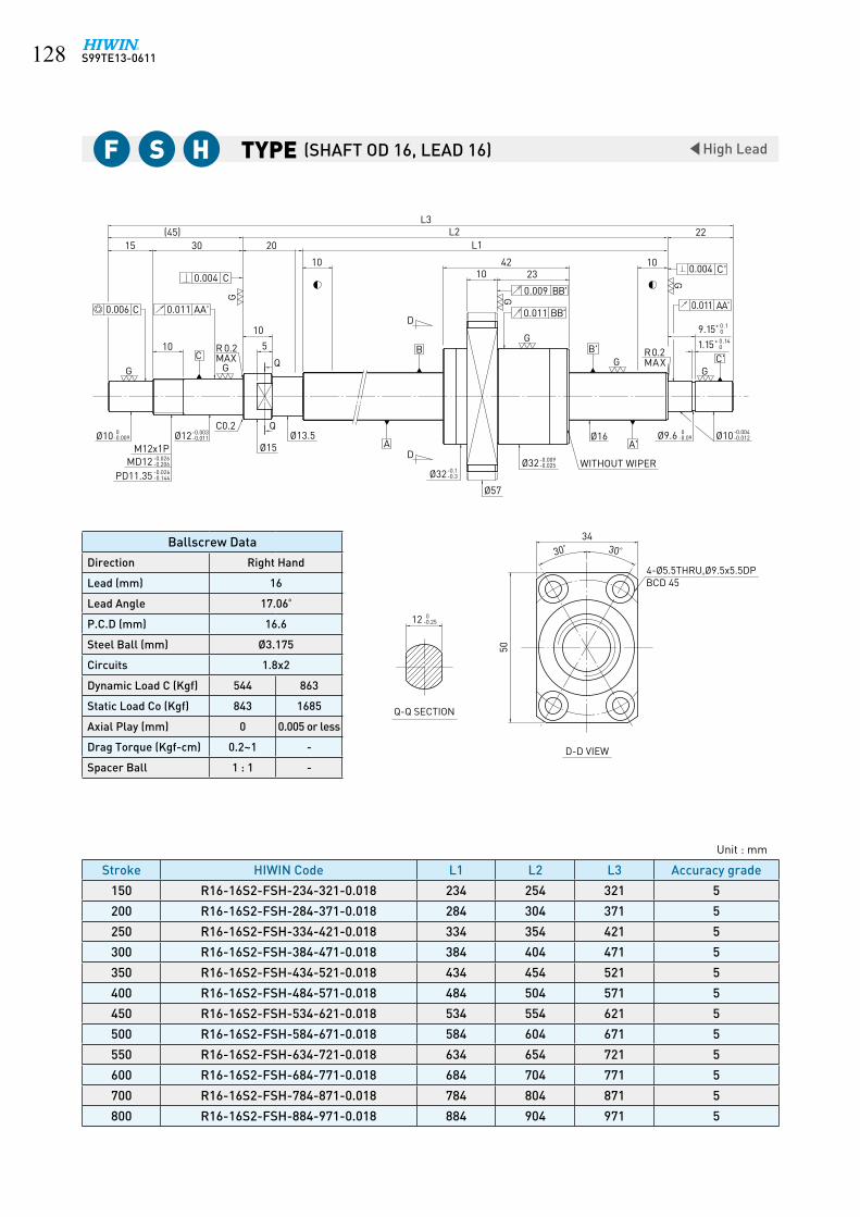
S99TE13-0611���
Type High Lead
Stroke HIWIN Code L1 L2 L3 Accuracy grade
150 R16-16S2-FSH-234-321-0.018 234 254 321 5
200 R16-16S2-FSH-284-371-0.018 284 304 371 5
250 R16-16S2-FSH-334-421-0.018 334 354 421 5
300 R16-16S2-FSH-384-471-0.018 384 404 471 5
350 R16-16S2-FSH-434-521-0.018 434 454 521 5
400 R16-16S2-FSH-484-571-0.018 484 504 571 5
450 R16-16S2-FSH-534-621-0.018 534 554 621 5
500 R16-16S2-FSH-584-671-0.018 584 604 671 5
550 R16-16S2-FSH-634-721-0.018 634 654 721 5
600 R16-16S2-FSH-684-771-0.018 684 704 771 5
700 R16-16S2-FSH-784-871-0.018 784 804 871 5
800 R16-16S2-FSH-884-971-0.018 884 904 971 5
Unit : mm
F S H (SHAFT OD 16, LEAD 16)
Ballscrew Data
Direction Right Hand
Lead (mm) 16
Lead Angle 17.06º
P.C.D (mm) 16.6
Steel Ball (mm) Ø3.175
Circuits 1.8x2
Dynamic Load C (Kgf) 544 863
Static Load Co (Kgf) 843 1685
Axial Play (mm) 0 0.005 or less
Drag Torque (Kgf-cm) 0.2~1 -
Spacer Ball 1 : 1 -
-0.003-0.011Ø12
B'
A'
C'C
D
D
Q
QC0.2
M12x1PØ13.5
Ø15
Ø57
Ø16
WITHOUT WIPERØ32
Ø32
231042
Ø10Ø9.6Ø10
R0.2MAX
0.011 AA'
R 0.2MAX
10
(45)20
0.006 C 0.011 AA'
C0.004 C'
BB'
BB'
50
30° 30°
34
G
GG
G
GG
GG
5
L2L3
15 30
10
22
9.15+ 0.10
1.15+ 0.140
1010
A
B
L1
-0.004-0.012
0-0.09
-0.009-0.025
-0.1-0.3
0-0.009
-0.026-0.206MD12-0.026-0.144PD11.35
12 0-0.25
D-D VIEW
Q-Q SECTION
BCD 454-Ø5.5THRU,Ø9.5x5.5DP
0.0040.009
0.011

S99TE13-0611 ���
Type High Lead
D-D VIEW
A'
B'
A
B C'C
BCD 59
Q-Q SECTION
52
WIPER BOTH ENDS
OIL HOLE
Q
Q
Ø19.5 Ø16.5
R0.2
C0.3
MAX
Ø74
Ø39M15x1.0PMD15 -0.026
-0.206
PD14.35 -0.026-0.144
12 0-0.011
Ø15-0.004-0.012
15.5
D
D
MAX
C0.5
R0.2
Ø14.3 0-0.11
Ø15-0.004-0.012
Ø20
Ø39
4-Ø6.6THRU,Ø11x6.5DP
17
3333
23 23
20
15 5
1540
(60)(25)
10 1031
L2L3
105
L1
10.15 +0.10
1.15+0.140
10
25
0.015 BB'
0.011 BB' 0.016 AA'
0.004 C'
0.007 C0.016 AA'
0.004 C
-0.009-0.025
-0.1-0.3
0-0.25
30°30°
G G
G
G
GG
G G
G
Stroke HIWIN Code L1 L2 L3 Accuracy grade
300 R20-20S2-FSH-410-520-0.018 410 435 520 5
400 R20-20S2-FSH-510-620-0.018 510 535 620 5
500 R20-20S2-FSH-610-720-0.018 610 635 720 5
600 R20-20S2-FSH-710-820-0.018 710 735 820 5
700 R20-20S2-FSH-810-920-0.018 810 835 920 5
800 R20-20S2-FSH-910-1020-0.018 910 935 1020 5
900 R20-20S2-FSH-1010-1120-0.018 1010 1035 1120 5
1000 R20-20S2-FSH-1110-1220-0.018 1110 1135 1220 5
1100 R20-20S2-FSH-1210-1320-0.018 1210 1235 1320 5
Unit : mm
F S H (SHAFT OD 20, LEAD 20)
Ballscrew Data
Direction Right Hand
Lead (mm) 20
Lead Angle 17.17º
P.C.D (mm) 20.6
Steel Ball (mm) Ø3.175
Circuits 1.8x2
Dynamic Load C (Kgf) 612 971
Static Load Co (Kgf) 1061 2122
Axial Play (mm) 0 0.005 or less
Drag Torque (Kgf-cm) 0.1~1 -
Spacer Ball 1 : 1 -

S99TE13-0611��0
Type High Lead
Stroke HIWIN Code L1 L2 L3 Accuracy grade
500 R25-20S2-FSH-610-751-0.018 610 640 751 5
600 R25-20S2-FSH-710-851-0.018 710 740 851 5
800 R25-20S2-FSH-910-1051-0.018 910 940 1051 5
1000 R25-20S2-FSH-1110-1251-0.018 1110 1140 1251 5
1200 R25-20S2-FSH-1310-1451-0.018 1310 1340 1451 5
1400 R25-20S2-FSH-1510-1651-0.018 1510 1540 1651 5
1600 R25-20S2-FSH-1710-1851-0.018 1710 1740 1851 5
Unit : mm
F S H (SHAFT OD 25, LEAD 20)
Ballscrew Data
Direction Right Hand
Lead (mm) 20
Lead Angle 13.76º
P.C.D (mm) 26
Steel Ball (mm) Ø4.763
Circuits 1.8x2
Dynamic Load C (Kgf) 1146 1819
Static Load Co (Kgf) 1968 3936
Axial Play (mm) 0 0.005 or less
Drag Torque (Kgf-cm) 0.2~1 -
Spacer Ball 1 : 1 -
Ø20
0-0.011Ø15
-0.026-0.206-0.026-0.144
10
20 10(30)
0.011 BB'
0.015 BB'
B'B
Q
L1
L3L2
Ø25 Ø21.5
12OIL HOLE 6
GG
3053
49
66
1.35
0.016 AA'
0.004 C'
31
16
0.004 C
5327(80)
GG
G
G G
G15
C0.0080.016 AA'
A'
M6x1Px8DP
D
D
C0.3C0.5
QCC0.5
M20x1P
Ø25A
C0.3C0.5
C'
Ø74
R0.2MAX
+0.10
+0.140
0-0.21Ø19
-0.005-0.014
R0.2MAX
-0.009-0.025Ø47-0.1
-0.3Ø47
Ø20-0.005-0.014
MD20PD19.35
0-0.3522
Q-Q SECTION
D-D VIEW
BCD 604-Ø6.6THRU,Ø11x6.5DP
30°30°
WITHOUT WIPER
15.35

S99TE13-0611 ���
Type Ultra High Lead
GB'
A'
B
A
D
D
G
G
13.534
OIL HOLE 0.011 BB'
G
0.004 C
0.014 AA'
CG
C'G
0.014 AA'
0.004 C'
G
C0.5C0.2
Ø13Ø15R0.2MAX
Q
QC0.5G
C0.5
0.009 C'
Q-Q SECTION
D-D VIEW
36
30°30°
50
BCD 454-Ø5.5THRU M6x1P
12
PD11.35 -0.026-0.144
MD12-0.026-0.206
M12x1P
Ø12-0.003-0.011Ø10 0
-0.009
15
105
1030
Ø34-0.009-0.025
Ø55
M5x0.8Px12DP
1.15
22
9.15
L3L2L1 HRC 58~62
(45)(12)
5
10
Ø10-0.004-0.012
Ø9.6 0-0.09
MAXR0.2
C0.5
Ø16
+0.10
+0.140
+0-0.2
Stroke HIWIN Code L1 L2 L3 Accuracy grade
300 2R16-32V2-DFSH-382-471-0.018 382 404 471 5
500 2R16-32V2-DFSH-582-671-0.018 582 604 671 5
800 2R16-32V2-DFSH-882-971-0.018 882 904 971 5
1200 2R16-32V2-DFSH-1282-1371-0.018 1282 1304 1371 5
Unit : mm
D F S H (SHAFT OD 16, LEAD 32)
Ballscrew Data
Direction Right Hand
Lead (mm) 32
Lead Angle 31.53º
P.C.D (mm) 16.6
Steel Ball (mm) Ø3.175
Circuits 0.7x2
Dynamic Load C (Kgf) 432
Static Load Co (Kgf) 755
Axial Play (mm) 0 0.005 MAX
Drag Torque (Kgf-cm) 0.15~1.0 0.24 MAX
Spacer Ball 1 : 1 -
6.6 Ultra High Lead Ground Ballscrew

S99TE13-0611���
Ultra High LeadType
-0.25 017
40
30°30°
15 0
+0.141.15
L2(60)
Q
Ø20
C0.5
R0.2MAX
-0.11 0Ø14.3
-0.012-0.004Ø15
10
5
L1 HRC 58~6225
M6x1Px15DP
Ø58-0.025-0.009Ø38
40 (15)
5
20
-0.011 0Ø12 -0.012
-0.004Ø15M15x1P
-0.206-0.026MD15-0.144-0.026PD14.35
M6x1Px8DP 4-Ø5.5THRUBCD 48
0+0.110.15
4120
-0.3-0.1Ø38
14
L3
D-D VIEW
Q-Q SECTION
G
MAX
0.009 C
C0.5G
C0.5 Q
C0.3Ø19.5 Ø17
R0.2C0.5
0.004 C'
0.014 AA'
GC
GC'
0.014 AA'
0.004 C
G
0.011 BB'HOLEOIL
G
G
D
D
A
B
A'
B'G
Stroke HIWIN Code L1 L2 L3 Accuracy grade
400 2R20-40V2-DFSH-506- 620-0.018 506 535 620 5
600 2R20-40V2-DFSH-706- 820-0.018 706 735 820 5
800 2R20-40V2-DFSH-906- 1020-0.018 906 935 1020 5
1000 2R20-40V2-DFSH-1106- 1220-0.018 1106 1135 1220 5
1200 2R20-40V2-DFSH-1306- 1420-0.018 1306 1335 1420 5
1600 2R20-40V2-DFSH-1706- 1820-0.018 1706 1735 1820 5
Unit : mm
D F S H (SHAFT OD 20, LEAD 40)
Ballscrew Data
Direction Right Hand
Lead (mm) 40
Lead Angle 31.47º
P.C.D (mm) 20.8
Steel Ball (mm) Ø3.175
Circuits 0.7x2
Dynamic Load C (Kgf) 500
Static Load Co (Kgf) 987
Axial Play (mm) 0 0.005 MAX
Drag Torque (Kgf-cm) 0.2~1.2 0.3 MAX
Spacer Ball - -

S99TE13-0611 ���
Type Ultra High Lead
63
L3L2
L1
-0.35 022
(36)20
G
(80)27 53
16
G
G
10
16 15
6
50
G
12 25
G
30° 30°
48
0+0.115.35
53
15
G
G
16
G
0+0.05
8°
20.1
15°
0.4
1.1
0.2
F0.4X0.2DIN509X DETAIL
0+0.141.35
M20X1P-0.206-0.026MD20
-0.144-0.026PD19.35
C0.3
M6x1Px8DP
Ø25
(OIL HOLE)
-0.21 0Ø19
-0.014-0.005Ø20
D
-0.025-0.009Ø46Ø70
Ø21Ø25 DC0.3
-0.206-0.026MD20
M20x1P-0.014-0.005Ø20
-0.144-0.026PD19.35
-0.011 0Ø15
4-Ø6.6THRU
WITHOUT WIPER
Q
Q
Q-Q SECTION
BCD 58
C C'
0.004 C
0.018 AA'0.010 C
0.013 AA'0.004 C'
B
A
B'
A'
0.011 BB'0.015 BB'
XX
D-D VIEW
+0.1 0+0.1 0
Stroke HIWIN Code L1 L2 L3 Accuracy grade
700 2R25-50V2-DFSH-844-1013-0.018 844 880 1013 5
1000 2R25-50V2-DFSH-1144-1313-0.018 1144 1180 1313 5
1500 2R25-50V2-DFSH-1644-1813-0.018 1644 1680 1813 5
2000 2R25-50V2-DFSH-2144-2313-0.018 2144 2180 2313 5
Unit : mm
D F S H (SHAFT OD 25, LEAD 50)
Ballscrew Data
Direction Right Hand
Lead (mm) 50
Lead Angle 31.67º
P.C.D (mm) 25.8
Steel Ball (mm) Ø3.969
Circuits 0.7x2
Dynamic Load C (Kgf) 719
Static Load Co (Kgf) 1475
Axial Play (mm) 0 0.005 or less
Drag Torque (Kgf-cm) 0.3~2.19 ~0.5
Spacer Ball 1 : 1 -
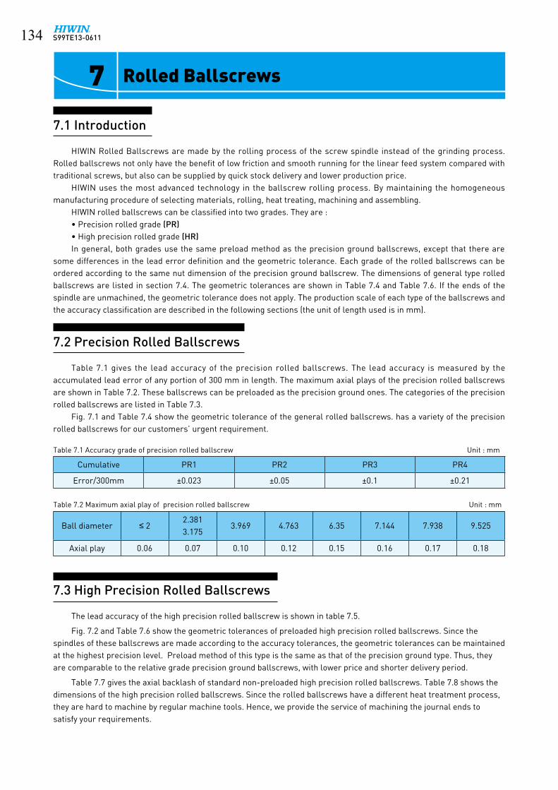
S99TE13-0611���
7 Rolled Ballscrews
7.1 Introduction
HIWIN Rolled Ballscrews are made by the rolling process of the screw spindle instead of the grinding process. Rolled ballscrews not only have the benefit of low friction and smooth running for the linear feed system compared with traditional screws, but also can be supplied by quick stock delivery and lower production price.
HIWIN uses the most advanced technology in the ballscrew rolling process. By maintaining the homogeneous manufacturing procedure of selecting materials, rolling, heat treating, machining and assembling.
HIWIN rolled ballscrews can be classified into two grades. They are :• Precision rolled grade (PR)• High precision rolled grade (HR)In general, both grades use the same preload method as the precision ground ballscrews, except that there are
some differences in the lead error definition and the geometric tolerance. Each grade of the rolled ballscrews can be ordered according to the same nut dimension of the precision ground ballscrew. The dimensions of general type rolled ballscrews are listed in section 7.4. The geometric tolerances are shown in Table 7.4 and Table 7.6. If the ends of the spindle are unmachined, the geometric tolerance does not apply. The production scale of each type of the ballscrews and the accuracy classification are described in the following sections (the unit of length used is in mm).
7.2 Precision Rolled Ballscrews
Table 7.1 gives the lead accuracy of the precision rolled ballscrews. The lead accuracy is measured by the accumulated lead error of any portion of 300 mm in length. The maximum axial plays of the precision rolled ballscrews are shown in Table 7.2. These ballscrews can be preloaded as the precision ground ones. The categories of the precision rolled ballscrews are listed in Table 7.3.
Fig. 7.1 and Table 7.4 show the geometric tolerance of the general rolled ballscrews. has a variety of the precision rolled ballscrews for our customers’ urgent requirement.
Table 7.1 Accuracy grade of precision rolled ballscrew Unit : mm
Cumulative PR1 PR2 PR3 PR4
Error/300mm ±0.023 ±0.05 ±0.1 ±0.21
Table 7.2 Maximum axial play of precision rolled ballscrew Unit : mm
Ball diameter ≤ 22.3813.175
3.969 4.763 6.35 7.144 7.938 9.525
Axial play 0.06 0.07 0.10 0.12 0.15 0.16 0.17 0.18
7.3 High Precision Rolled Ballscrews
The lead accuracy of the high precision rolled ballscrew is shown in table 7.5.
Fig. 7.2 and Table 7.6 show the geometric tolerances of preloaded high precision rolled ballscrews. Since the spindles of these ballscrews are made according to the accuracy tolerances, the geometric tolerances can be maintained at the highest precision level. Preload method of this type is the same as that of the precision ground type. Thus, they are comparable to the relative grade precision ground ballscrews, with lower price and shorter delivery period.
Table 7.7 gives the axial backlash of standard non-preloaded high precision rolled ballscrews. Table 7.8 shows the dimensions of the high precision rolled ballscrews. Since the rolled ballscrews have a different heat treatment process, they are hard to machine by regular machine tools. Hence, we provide the service of machining the journal ends to satisfy your requirements.

S99TE13-0611 ���Table 7.3 Category of HIWIN precision rolled ballscrew Unit : mm
Nominal diameter do
( mm )
LeadMax.screw
length2 2.5 3 4 5 5.08 6 8 10 12 16 20 25 32 40 50
8 ● ■ ● 800
10 ● ■ ● ● ● 1000
12 ● ■ ● ■ ● ● ● 1200
14 ■ ● ● ● 1400
15 ● ● ● 1500
16 ■ ■ ■ ■ ■ ● 1600
20 ■ ■ ■ ● ● ● ● 2000
25 ■ ■ ● ■ ● 2500
28 ● ● ● 2500
32 ■ ■ ● ● ● ● 3200
36 ● ● ● ● ● ● ● 3600
40 ■ ■ ● ● ● ● ● ● 4000
45 ● ● ● 4600
50 ● ● ● ● ● ● ● ● 5000
55 ● 5500
63 ■ ● ■ ● 5750
■ : Right and left hand ballscrews ● : Right hand ballscrews only
PRT4 C
PRT2 AA'
PRT3 C C
L2 L1
bearing seat
2do
A
ØDf ØD Ødo
A'
2do
L1
bearing seat
L2
C'
PRT2 AA'
PRT4 C'
PRT1 AA'
Lt
bearing seat
L2 L1 ØD Ødo
HRT2 AA'
HRT3 C
2do
A
ØDf
A'
2do
L1
bearing seat
L2
HRT4 C'
HRT2 AA'
C'
HRT1 AA'
2do
B'
Lt
2do
BC
HRT4 C
Fig. 7.1 Geometric tolerance of HIWIN precision rolled ballscrew
Fig. 7.2 Geometric tolerance of HIWIN high precision rolled ballscrew
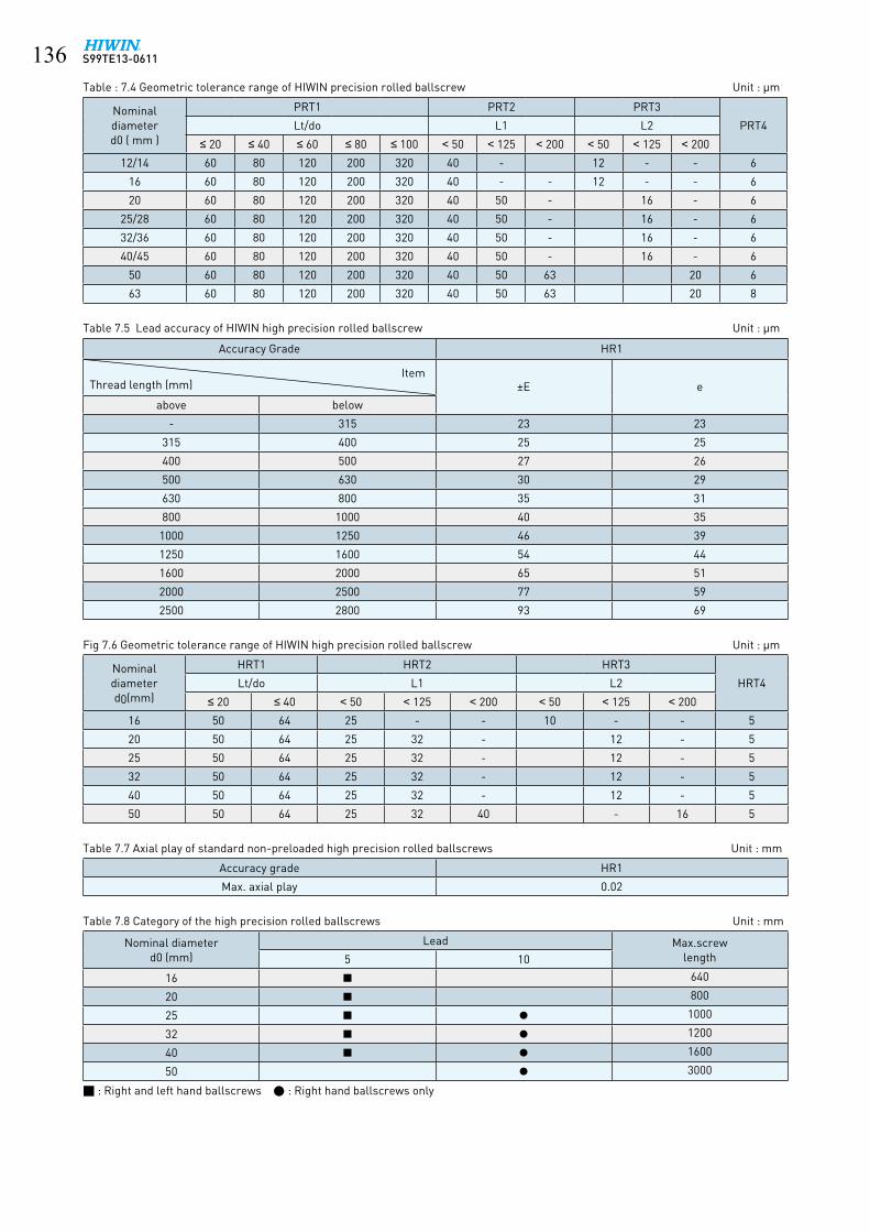
S99TE13-0611���Table : 7.4 Geometric tolerance range of HIWIN precision rolled ballscrew Unit : μm
Nominaldiameterd0 ( mm )
PRT1 PRT2 PRT3
PRT4Lt/do L1 L2
≤ 20 ≤ 40 ≤ 60 ≤ 80 ≤ 100 < 50 < 125 < 200 < 50 < 125 < 200
12/14 60 80 120 200 320 40 - 12 - - 6
16 60 80 120 200 320 40 - - 12 - - 6
20 60 80 120 200 320 40 50 - 16 - 6
25/28 60 80 120 200 320 40 50 - 16 - 6
32/36 60 80 120 200 320 40 50 - 16 - 6
40/45 60 80 120 200 320 40 50 - 16 - 6
50 60 80 120 200 320 40 50 63 20 6
63 60 80 120 200 320 40 50 63 20 8
Table 7.5 Lead accuracy of HIWIN high precision rolled ballscrew Unit : μm
Accuracy Grade HR1
ItemThread length (mm) ±E e
above below
- 315 23 23
315 400 25 25
400 500 27 26
500 630 30 29
630 800 35 31
800 1000 40 35
1000 1250 46 39
1250 1600 54 44
1600 2000 65 51
2000 2500 77 59
2500 2800 93 69
Fig 7.6 Geometric tolerance range of HIWIN high precision rolled ballscrew Unit : μm
Nominaldiameterd0(mm)
HRT1 HRT2 HRT3
HRT4Lt/do L1 L2
≤ 20 ≤ 40 < 50 < 125 < 200 < 50 < 125 < 200
16 50 64 25 - - 10 - - 5
20 50 64 25 32 - 12 - 5
25 50 64 25 32 - 12 - 5
32 50 64 25 32 - 12 - 5
40 50 64 25 32 - 12 - 5
50 50 64 25 32 40 - 16 5
Table 7.7 Axial play of standard non-preloaded high precision rolled ballscrews Unit : mm
Accuracy grade HR1
Max. axial play 0.02
Table 7.8 Category of the high precision rolled ballscrews Unit : mm
Nominal diameter d0 (mm)
Lead Max.screw length5 10
16 ■ 640
20 ■ 800
25 ■ ● 1000
32 ■ ● 1200
40 ■ ● 1600
50 ● 3000
■ : Right and left hand ballscrews ● : Right hand ballscrews only

S99TE13-0611 ���
page General Type page
138
Flange end, single nut, tube within the nut diameter
Round, single nut,tube above the nut diameter
139
140
Round, single nut, bonded return tube Flange end, single nut, bonded return tube
141
142
Flange end, single nut,tube above the nut diameter
Square, single nut,tube above the nut diameter
143
page High Lead Type page
144
Large lead, flange mounted, single nut, end cap
144
7.4 General Type of Rolled Ballscrews
FSW
RSB FSB
FSV
FSH
SSV
RSV
*Different design required by the drawing approval, please contact with HIWIN engineers for the other type listed above.*Double asterisks( ): Self-Lubricating Ballscrew E2 design is available, except the shaft diameter under 16mm or ball diameter under 2.381mm.

S99TE13-0611���
TypeF S W
7.5 Dimensions for Rolled Ballscrews
Model
SizeBallDia.
Circuits
DynamicLoad
1x10⁶ revsC ( kgf )
Static Load
Co ( kgf )
Nut FlangeFit
NominalDia.
Lead L D F BCD-E TBolt
X Y Z S
8-2.5B1 82.5 2.000
2.5x1 218 317 34 26 47 35 8 5.5 9.5 5.5 8
10-2.5B110
2.5x1 252 405 34 28 52 38 8 5.5 9.5 5.5 8
10-4B14 2.381
2.5x1 304 466 41 30 53 41 10 5.5 9.5 5.5 10
12-4B1 12 2.5x1 344 574 41 30 50 40 10 5.5 9.5 5.5 12
16-5B1 16
5 3.175
2.5x1 679 1226 43 40 64 51 10 5.5 9.5 5.5 12
20-5C1 20 3.5x1 1001 2149 50 44 68 55 12 5.5 9.5 5.5 12
25-5B225
2.5x2 1534 3975 60 50 74 62 12 5.5 9.5 5.5 12
25-10B1 10 4.763 2.5x1 1459 2983 65 60 86 73 16 6.6 11 6.5 12
32-5B232
5 3.175 2.5x2 1702 5098 60 58 84 71 12 6.6 11 6.5 12
32-10B2
10 6.350
2.5x2 4379 10345 98 74 108 90 16 9 14 8.5 15
40-10B2 40 2.5x2 4812 12732 102 84 125 104 18 11 17.5 11 15
50-10C2 50 3.5x2 7146 22477 126 94 135 114 18 11 17.5 11 20
63-10C2 63 3.5x2 7869 28290 128 110 152 130 20 11 17.5 11 20
ØDg6 ØD-0.1-0.3ØF
ØX
T<12 M6x1P
OIL HOLET≥12 1/8PT
BCD E
30°
30°
S
ØY
Z
T
L

S99TE13-0611 ���
TypeR S V
Model
SizeBallDia.
Circuits
DynamicLoad
1x10⁶ revsC ( kgf )
Static Load
Co ( kgf )
NutMounting
Thread
MountingThreadLength
ReturnTube Width
ReturnTube Height
NominalDia.
Lead L D M J W H
8-2.5B1 82.5 2.000
2.5x1 218 317 28 18 M18x1P 10 15 15
10-2.5B110
2.5x1 252 405 30 20 M18x1P 10 17 17
10-4B14 2.381
2.5x1 305 466 32 23 M22x1P 10 20 20
12-4B1 12 2.5x1 344 574 32 25 M24x1P 10 22 21
16-5B116
5
3.175
2.5x1 679 1226 40 31 M28x1.5P 10 23 25
16-5.08B15.08
2.5x1 763 1399 45 30 M25x1.5P 13 24 21
16-5.08C1 16 3.5x1 1013 1945 45 30 M25x1.5P 13 24 21
20-5C1 205
3.5x1 1001 2149 45 35 M32x1.5P 12 27 22
25-5B225
2.5x2 1534 3975 58 40 M38x1.5P 16 31 25
25-10B2 10 4.763 2.5x2 2663 6123 94 45 M38x1.5P 16 38 32
32-5B232
5 3.175 2.5x2 1702 5098 60 54 M50x2P 18 38 29
32-10B2
10 6.350
2.5x2 4379 10345 95 58 M52x2P 18 44 36
40-10B2 40 2.5x1 4812 12732 102 65 M60x2P 25 52 41
50-10C2 50 3.5x2 7146 22477 130 80 M75x2P 30 62 46
63-10C263
3.5x2 7869 28290 132 95 M90x2P 40 74 52
63-12C3 12 7.938 3.5x3 16828 58535 205 102 M95x3P 35 75 59
M ØD
Wm
ax
Hmax J
L

S99TE13-0611��0
TypeR S B
Model
SizeBallDia.
Circuits
DynamicLoad
1x10⁶ revsC ( kgf )
Static Load
Co ( kgf )
NutMounting
ThreadMounting
Thread Length
NominalDia.
Lead L D M J
8-2.5B1 82.5 2.000
2.5x1 218 317 24 22 M18x1P 7.5
10-2.5B110
2.5x1 252 405 24 24 M20x1P 7.5
10-4B14 2.381
2.5x1 304 466 34 26 M22x1P 10
12-4B1 12 2.5x1 344 574 34 28 M25x1.5P 10
16-5B1 16
53.175
2.5x1 679 1226 42 36 M30x1.5P 12
20-5C1 20 3.5x1 1001 2149 54 40 M36x1.5P 14
25-5B2 25 2.5x2 1534 3975 69 46 M42x1.5P 19
32-5B232
5 2.5x2 1702 5098 69 54 M50x2P 19
32-10B2
10 6.350
2.5x2 4379 10345 105 68 M62x2P 19
40-10B2 40 2.5x2 4812 12732 110 76 M70x2P 24
50-10C2 50 3.5x2 7146 22477 135 88 M82x2P 29
63-10C2 63 3.5x2 7869 28290 135 104 M95x2P 29
M ØD
J
L

S99TE13-0611 ���
TypeF S B
Model
SizeBallDia.
Circuits
DynamicLoad
1x10⁶ revsC ( kgf )
Static Load
Co ( kgf )
Nut Flange
NominalDia.
Lead L D F BCD-E TBolt
X Y Z
8-2.5B1 82.5 2.000
2.5x1 218 317 34 22 43 31 8 5.5 9.5 5.5
10-2.5B110
2.5x1 252 405 34 24 46 34 8 5.5 9.5 5.5
10-4B1
4 2.381
2.5x1 304 466 41 26 49 37 10 5.5 9.5 5.5
12-4B112
2.5x1 344 574 41 28 51 39 10 5.5 9.5 5.5
12-4C1 3.5x1 459 803 44 30 50 40 10 4.5 8 4.5
14-4C114
3.5x1 498 943 40 31 50 40 10 4.5 8 4.5
14-5B1 5 3.175 2.5x1 636 1095 40 32 50 40 10 4.5 8 4.5
16-4B1
16
4 2.381 2.5x1 390 744 41 35 56 43 10 5.5 9.5 5.5
16-5B1 53.175
2.5x1 679 1226 43 36 60 47 10 5.5 9.5 5.5
16-10B1 10 2.5x1 667 1194 52 36 60 47 12 6.6 11 6.5
20-4C1
20
4 2.381 3.5x1 582 1329 40 40 60 50 10 4.5 8 4.5
20-5B1
5 3.175
2.5x1 745 1526 40 40 60 50 10 4.5 8 4.5
20-5C1 3.5x1 1001 2149 50 40 64 51 12 5.5 9.5 5.5
25-5B125
2.5x1 845 1987 40 43 67 55 10 5.5 9.5 5.5
25-5B2 2.5x2 1534 3975 60 46 70 58 12 5.5 9.5 5.5
32-5B232
2.5x2 1702 5098 60 54 80 67 12 6.6 11 6.5
32-10B2
10 6.350
2.5x2 4379 10345 98 68 102 84 16 9 14 8.5
40-10B2 40 2.5x2 4812 12732 102 76 117 96 18 11 17.5 11
50-10C2 50 3.5x2 7146 22477 126 88 129 108 18 11 17.5 11
63-10C2 63 3.5x2 7869 28290 128 104 146 124 20 11 17.5 11
ØDg6ØF
ØX
T<12 M6x1P
OIL HOLET≥12 1/8PT
BCD E
30°
30°
ØY
Z
T
L

S99TE13-0611���
TypeF S V
Model
SizeBallDia.
Circuits
DynamicLoad
1x10⁶ revsC ( kgf )
Static Load
Co ( kgf )
Nut FlangeReturnTube
Bolt Fit
NominalDia.
Lead L D F T BCD-E W H X Y Z S
8-2.5B1 82.5 2.000
2.5x1 218 317 34 18 41 8 29 15 15 5.5 9.5 5.5 8
10-2.5B110
2.5x1 252 405 34 20 43 8 31 17 17 5.5 9.5 5.5 8
10-4B14 2.381
2.5x1 304 466 41 23 46 10 34 20 20 5.5 9.5 5.5 10
12-4B1 12 2.5x1 344 574 41 25 48 10 36 22 21 5.5 9.5 5.5 12
16-5B1 16
53.175
2.5x1 679 1226 43 31 55 10 42 23 25 5.5 9.5 5.5 12
20-5C1 20 3.5x1 1001 2149 50 35 59 12 46 27 22 5.5 9.5 5.5 12
25-5B2 25 2.5x2 1534 3975 60 40 64 12 52 31 25 5.5 9.5 5.5 12
32-5B232
6.350
2.5x2 1702 5098 60 54 80 12 67 38 29 6.6 11 6.5 12
32-10B2
10
2.5x2 4379 10345 98 58 92 16 74 44 36 9 14 8.5 15
40-10B2 40 3.5x2 4812 12732 102 65 106 18 85 52 41 11 17.5 11 15
50-10C2 50 3.5x2 7146 22477 126 80 121 18 100 62 46 11 17.5 11 20
63-10C2 63 3.5x2 7869 28290 128 95 137 20 115 74 52 11 17.5 11 20
ØFØD-0.1
-0.3ØDg6
30°30°
Wm
ax
Hmax
BCD E
ØX
ØY
L
Z
ST
T<12 M6x1P
OIL HOLET≥12 1/8PT

S99TE13-0611 ���
TypeS S V
Model
Size
BallDia.
Circuits
DynamicLoad
1x10⁶ revsC ( kgf )
Static Load
Co ( kgf )W F L B C T M (max)Nominal
Dia.Lead
14-4B1
144 2.381
2.5x1 376 682 34 13 35 26 22 6 30
14-4C1 3.5x1 498 943 34 13 35 26 22 6 30
14-5B1
5 3.175
2.5x1 636 1095 34 13 35 26 22 6 31
16-5B1 16 2.5x1 679 1226 42 16 36 32 22 21.5 32.5
20-5B120
2.5x1 745 1526 48 17 35 35 22 9 39
20-10B1 10 4.763 2.5x1 1280 2314 48 18 58 35 35 9 46
25-5B125
5 3.175 2.5x1 845 1987 60 20 35 40 22 9.5 45
25-10B2 10 6.350 2.5x2 3816 7968 60 23 94 40 60 10 54
28-6B128 6 3.969
2.5x1 1203 2796 60 22 42 40 18 10 50
28-6B2 2.5x2 2184 5592 60 22 67 40 40 10 50
32-10B132
10 6.350
2.5x1 2413 5172 70 26 64 50 45 12 62
32-10B2 2.5x2 4379 10345 70 26 94 50 60 12 67
36-10B2 36 2.5x2 4592 11403 86 29 96 60 60 17 67
45-12B2 45 12 7.144 2.5x2 5963 16110 100 36 115 75 75 20.5 80
W B
4-H
M max
FA
8°
T
L
C

S99TE13-0611���
TypeF S H
Model
Size
BallDia.
Circuits
DynamicLoad
1x10⁶ revsC ( kgf )
Static Load
Co ( kgf )
Nut Flange Bolt Fit
NominalDia.
LeadD L F T BCD-E H X S M
16-16S2
16 16
3.175
1.8x2 710 138032 48 53 10 42 38 4.5 26 0
16-16S4 1.8x4 1290 2760
16-16S2 1.8x2 710 138033 48 58 10 45 38 6.6 26 0
16-16S4 1.8x4 1290 2760
20-20S2
20 20
1.8x2 800 1740 39 48 62 10 50 46 5.5 27.5 0
20-20S2 1.8x2 800 174038 58 62 10 50 46 5.5 32.5 3
20-20S4 1.8x4 1450 3480
25-25S225 25 3.969
1.8x2 1210 280047 67 74 12 60 56 6.6 39.5 3
25-25S4 1.8x4 2190 5600
32-32S232 32 4.763
1.8x2 1720 428058 85 92 15 74 68 9 48 0
32-32S4 1.8x4 3110 8530
40-40S240 40 6.350
1.8x2 2810 717072 102 114 17 93 84 11 60 0
40-40S4 1.8x4 5100 14330
50-50S250 50 7.938
1.8x2 4120 1089090 125 135 20 112 104 14 83.5 0
50-50S4 1.8x4 7470 21780
OIL HOLE
F
ØDg6ØD
M M
S
L
T4-ØxTHRUBCD E
M6x1P
30°30°
H

S99TE13-0611 ���
Type Stock
Model
SizeBallDia.
Circuits
DynamicLoad
1x10⁶ revsC ( kgf )
Static Load
Co ( kgf )D D4
FlangeHole No.
D5 D6 H1 L1 L2 L7 L11M-OilHoleNominal
Dia.Lead
16-5T3 16
5 3.175
3 664 1196 28 38 6 5.5 48 40 10 40 10 5 M6x1P
20-5T320
3 733 1495 36 47 6 6.6 58 44 10 44 10 5 M6x1P
20-5T4 4 939 1993 36 47 6 6.6 58 44 10 52 10 5 M6x1P
25-5T3
25
3 880 2082 40 51 6 6.6 62 48 10 44 10 5 M6x1P
25-5T4 4 1127 2776 40 51 6 6.6 62 48 10 52 10 5 M6x1P
25-10T3 10 4.763 3 1430 2914 40 51 6 6.6 62 48 16 65 10 5 M6x1P
32-5T3
32
5 3.175
3 1008 2773 50 65 6 9 80 62 10 46 12 6 M6x1P
32-5T4 4 1291 3697 50 65 6 9 80 62 10 53 12 6 M6x1P
32-5T6 6 1830 5545 50 65 6 9 80 62 10 66 12 6 M6x1P
32-10T310 6.350
3 2264 4803 50 65 6 9 80 62 16 74 12 6 M6x1P
32-10T4 4 2900 6404 50 65 6 9 80 62 16 85 12 6 M6x1P
40-5T4
40
5 3.1754 1414 4621 63 78 8 9 93 70 10 53 14 7 M8x1P
40-5T6 6 2004 6932 63 78 8 9 93 70 10 66 14 7 M8x1P
40-10T310 6.350
3 2652 6367 63 78 8 9 93 70 16 74 14 7 M8x1P
40-10T4 4 3396 8489 63 78 8 9 93 70 16 87 14 7 M8x1P
50-5T4
50
5 3.1754 1562 5940 75 93 8 11 110 85 10 57 16 8 M8x1P
50-5T6 6 2214 8910 75 93 8 11 110 85 10 70 16 8 M8x1P
50-10T3
10 6.350
3 3045 8334 75 93 8 11 110 85 16 78 16 8 M8x1P
50-10T4 4 3899 11112 75 93 8 11 110 85 16 89 16 8 M8x1P
50-10T6 6 5526 16668 75 93 8 11 110 85 16 112 16 8 M8x1P
7.6 Dimensions for Stock Rolled Ballscrews
F S I (DIN 69051 part 5 form B)
M6x1P(M8x1P)L11OIL HOLE
ØD-0.2-0.3ØDg6
ØD6
TYPE 2TYPE 1
D5
D4
45°
22.5°30° 15°
30 °
H1 H1
L1
L2
L7

S99TE13-0611���
Type StockR S I
Model
Size
BallDia.
Circuits
DynamicLoad
1x10⁶ revsC ( kgf )
Static Load
Co ( kgf ) L D M JNominal
Dia.Lead
8-2.5T2 82.5 2.000
2 133 178 23.5 17.5 M15x1P 7.5
10-2.5T2 10 2 178 263 25 19.5 M17x1P 7.5
10-4T2 10 4 2.381 2 198 282 32 24 M22x1P 10
DM
J
L
(with V-thread)

S99TE13-0611 ���
Type StockF S B
DM
J
L
Model
Size
BallDia.
Circuits
DynamicLoad
1x10⁶ revsC ( kgf )
Static Load
Co ( kgf ) L D M JNominal
Dia.Lead
12-4B1 12 4 2.381 2.5x1 344 574 34 25.5 M20x1P 10
(with V-thread)

S99TE13-0611���
8 Ballscrew Retrofit Kits for Manual Milling Machine
8.1 Precision Ground Ballscrew Set
1. Precision ground, lead accuracy within ±0.0005” /ft.2. Stock size meet various CNC systems’ requirements.3. High strength and long service life.
X-AXISR.H.
2-Ø0.42 DRILL THRU.BCD 2.3
1.12max
45 °
1.48
max
2.52
30°
2.677
Ø0.156 DRILL THRU.
0.54.93
3.2 1.1 0.134.0
0.4
0.2
0.47
AB
2.28±0.059
G 0.00087 BB'
0.00063 BB'B'B G
4.50.13 0.67
G
4.53.2
0.00016 C'
0.00063 AA'
0.00031 C'
C'0.75 Ø0.75xW 0.1220.125
0.00016 C
G
0.00063 AA'
0.00031 C
GC
0.5
0.75Ø0.75xW 0.1220.125
G
1/2" - 20 UNF0.78710.7868
0.62450.6242
0.240.25
G
Ø1.03
Ø1.15
A'1.261.25
1.6851.681
1.6871.686Ø2.87
A
Ø1.15
Ø1.03G
0.78710.7868
0.62450.62421/2" - 20 UNF
0.240.25
Y - AXISL.H.
2-Ø0.42 DRILL THRU.BCD 2.3
30°
1.12max
Ø0.156 DRILL THRU.
1.48
max
0.54.93
3.2 1.1 0.131.6
C
2.38
0.75
G
0.00016 C
0.00063 AA'
0.00031 C
Ø0.75xW 0.1220.125 C
G
G
A A'
B'
0.2
G
G
0.4
B
D
2.28±0.0590.47
0.00087 BB'
0.00063 BB'
0.240.25
1/2" - 20 UNF0.62450.6242
0.78710.7868
Ø1.03
Ø1.151.6851.681
1.6871.686 Ø2.87
1.261.25ØØØØØ
Ø
ØØØØØØ
unit: inch

S99TE13-0611 ���
Traverse Screw (X Axis) in
Traverse Screw A B Part Number
32 42 24.07 B3205X-32
36 46 28.07 B3205X-36
42 52 34.07 B3205X-42
48 58 40.07 B3205X-48
Crossfeed Screw (Y Axis) in.
Table Size C D Part Number
9 20.3 13.77 B3205Y-9
12 23.3 16.77 B3205Y-12
16 27.3 20.77 B3205Y-16
P.C.Dia. 1.28"
Ball Dia. 0.125"
Lead Angle 2.84°
Circuits 2.5x2
Lead 5TPI
Static Load 12491 lbf
Dynamic Load(1x10⁶revs) 4158 lbf
Lead Accuracy 0.0003"/2π; 0.0005"/ft
Drag Torque(Preload) 3.5in-lb (280lbs)
4in
(B3205X)
(B3205H)
(B3205Y)
X AXIS
HOUSING
Y AXIS

S99TE13-0611��0
9 Multi-Solutions
• Features :• Cost savings :
The E2 series saves cost by eliminating piping joint systems, change and waste disposal, and by reducing oil purchases.
• Greatly extends the maintenance period : The E2 series will supply proper lubrication for long periods of time extending the maintenance period.
• Easy maintenance : The special construction of the E2 design requires no tools to replace the oil cartridge. There is no disassembly required when adding the E2 option.
• Ideal lubrication position : The lubrication point is located inside the ball nut allowing for the lubrication to be firmly applied onto the ball tracks.
• Effortless and flexible installation : The lubrication performs properly in every direction so there are no restrictions when installing the E2.
• Clean and environmentally friendly : Prevents oil leakage, making the E2 the ideal solution for clean room environments.
• Interchangeable oil selection : The replaceable oil cartridge can be refilled with any approved lubrication oil.
• Applications for special environmentsThe lubrication oil can be combined with grease for better results, especially in dusty, dirty, or wet environments.
• Characteristic of lubrication oilThe E2 self-lubrication cartridge is equipped with synthetic hydrocarbon based oil. The lubricate oil has a viscosity grade of ISO VG680.
9.1 E2 Self - lubricant
The E2 is compatible with mineral, hydrocarbon, and ester based greases. The E2 can accept synthetic oils with stable characteristics. A high viscosity grade will work well in conditions where there are high and low temperatures.
The low fluid draft factor prevents excessive power consumption and deters against corrosion and rust.
A compatible lubricate oil with the same viscosity grade can also be used in the replaceable cartridge.
• Application :- Machine tools- Industrial machinery : printing machine, paper-
processing machine, automatic machine, textile machine, cutting and grinding machines, etc.
- Electronic machinery : robots, measuring equipment, X-Y tables, etc.
- Miscellaneous: medical equipment, factory automation equipment, etc.
• Specification number :Example: R40 - 10B2 - FSWE2 - 800 - 1000 - 0.008
↓HIWIN E2 code
• Specification :Nut type : FSV, FDV, FSW, FDW, PFDW, OFSW, DFSV, FSH Please contact HIWIN engineers with other specification needs.In order to get the good lubrication efficiency; please notify HIWIN engineers of the ballscrew installation direction.

S99TE13-0611 ���
Test condition 1 : specification : ø50 x 30speed : 2500 rpm ( 75 m/min)stroke : 1180 mm
• Performance :
* Note : above test with no grease added
Running Distance
HIWIN E2
100 Km
0 10000 20000 30000 40000 50000 60000 km
Withoutlubrication
60000 km test continued
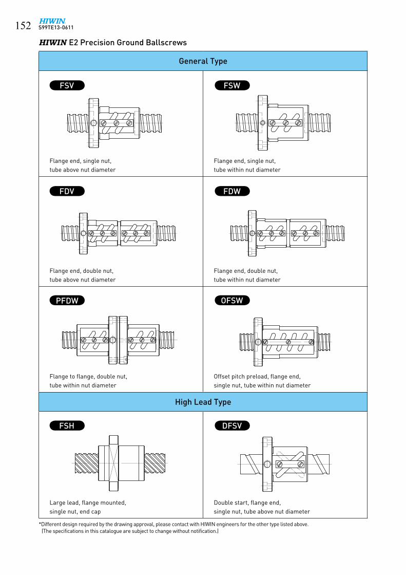
S99TE13-0611���HIWIN E2 Precision Ground Ballscrews
General Type
Flange end, single nut,tube above nut diameter
Flange end, single nut,tube within nut diameter
Flange end, double nut,tube above nut diameter
Flange end, double nut,tube within nut diameter
Flange to flange, double nut,tube within nut diameter
Offset pitch preload, flange end,single nut, tube within nut diameter
High Lead Type
Large lead, flange mounted, single nut, end cap
Double start, flange end, single nut, tube above nut diameter
FSV
FDV FDW
PFDW
FSH
OFSW
FSW
DFSV
*Different design required by the drawing approval, please contact with HIWIN engineers for the other type listed above.(The specifications in this catalogue are subject to change without notification.)

S99TE13-0611 ���
ModelBearing
Nut Flange Bolt BushOil holeDynamic
Load(kgf)Static
Load(kgf) D G L C F T t BCD-E BCD-e θ M X d B H A16-16S2 1299 1826 52 25 44 11.4 68 13 6 60 26 20 M4x0.7P 4.5 33 40 11 2 M4x0.7P20-20S2 1762 2531 62 30 50 12 78 13 6 70 31 20 M5x0.8P 4.5 39 50 11 2 M4x0.7P25-25S2 1946 3036 72 37 63 16.5 92 13 6 81 38 20 M6x1P 5.5 47 58 15.5 3 M4x0.7P32-32S2 3150 5035 80 47 80 21 105 20 9 91 48 25 M6x1P 6.6 58 66 20 3 M6x0.75P40-40S2 4800 8148 110 62 98 22.5 140 20 9 123 61 25 M8x1.25P 9 73 90 21.5 3 M6x0.75P
• Application:Semi-conductor industries, Robots, Wood machines,
Laser cutting machines, Transporting equipment.
• Features:1. Compact and high positioning:
It is a compact design using nut and support bearing as an integral uint. 45-degree steel ball contact angle make a better axial load. Zero backlash and higher stiffness construction give a high positioning.
2. Simple installation:
It is installed simply by fixing the nut on the housing with bolts.
3. Rapid feed:
No inertial effect produced by the integral unit rotating and the shaft fixed. Can select smaller power to meet the rapid feed requirement.
4. Stiffness:
Have a higher trust and moment stiffness, because the integral unit have an angular contact construction. There is no backlash while rolling.
5. Quietness:
Special end cap design allows steel balls circulating inside the nut. Noise generated by high speed operation lower than ordinary ballscrew.
• Specification:Example: 2R40-40S2-DFSHR1-800-1000-0.018
↓
HIWIN R1 code
9.2 R1 Rotating Nut
R1 ROTATING NUT
30°
30°
4-MBCD e
m
6-ØxTHRUBCD E
A
H
C
T
t
LG±1.5
ØdH7
ØBh7 ØF
ØDg6
θ θ
China Patent No. 422327Germany Patent No. 10108647.4Taiwan Patent No.166845U.S.A. Patent No. 6406188B1

S99TE13-0611���
9.3 Heavy Load Drive
• Application:High-load ball screw can be used for application on injection molding machines, die casting machines, general presses, power cylinders, robot ...
• Features:1. Heavy Load
A. 2~3 times load capacity than general standard series.
B. High axial load and acceleration.
C. Special lubrication design for short stroke.
2. Accuracy
JIS C5 and JIS C7
3. High Speed Operation and High Life
Enforced ball circulation systems for high speed condition and achieve long service life.
4. Option
Design in HIWIN Self-lubricant E2 Series.
Model No.Shaft
diameterLead
Turns Circuits
DynamicC N (kgf)
StaticCo N (kgf)
D L F T E X H W M
50-16B250
16
2.5x2 235000 (24000) 497000 (50700) 95 165 127 28 110 9 68 69 10150-16B3 2.5x3 334000 (34100) 746000 (76100) 95 213 127 28 110 9 68 69 11755-16B2
552.5x2 255000 (26000) 535000 (54600) 100 165 132 28 115 9 71 74 101
55-16B3 2.5x3 361000 (36800) 804000 (82000) 100 213 132 28 115 9 71 74 11763-16B2
632.5x2 280000 (28600) 613000 (62500) 105 165 137 28 120 9 73 82 101
63-16B3 2.5x3 398000 (40600) 918000 (93700) 105 213 137 28 120 9 73 82 11780-16B2
802.5x2 322000 (32900) 765000 (78100) 120 170 158 32 139 11 81 98 106
80-16B3 2.5x3 458000 (46700) 1150000 (117000) 120 218 158 32 139 11 81 98 12280-25B3 25 2.5x3 650000 (66300) 2010000 (205000) 145 338 185 40 165 11 102 100 140100-16B3
10016 2.5x3 493000 (50300) 1430000 (146000) 140 218 178 32 159 11 91 117 122
100-25B325
2.5x3 738000 (75300) 2596000 (264900) 159 338 199 40 179 11 109 118 140100-25B4 2.5x4 945000 (96400) 3461000 (353200) 159 413 199 40 179 11 109 118 165
BALLSCREW FOR HEAVy-LOAD DRIVE
5-ØxTHRU
1/8PTx10DPOIL HOLE
BCD E
H max
W m
ax
30°30°
T
M
L
ØDØF
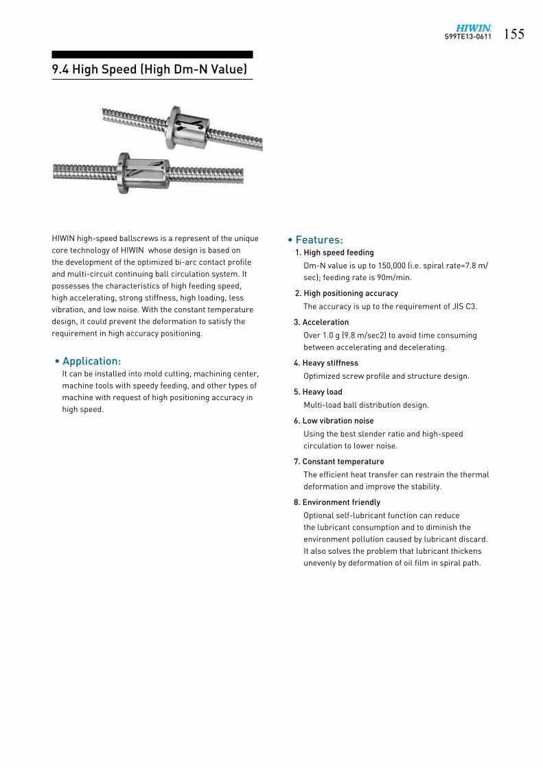
S99TE13-0611 ���
HIWIN high-speed ballscrews is a represent of the unique core technology of HIWIN whose design is based on the development of the optimized bi-arc contact profile and multi-circuit continuing ball circulation system. It possesses the characteristics of high feeding speed, high accelerating, strong stiffness, high loading, less vibration, and low noise. With the constant temperature design, it could prevent the deformation to satisfy the requirement in high accuracy positioning.
• Application:It can be installed into mold cutting, machining center, machine tools with speedy feeding, and other types of machine with request of high positioning accuracy in high speed.
• Features:1. High speed feeding
Dm-N value is up to 150,000 (i.e. spiral rate=7.8 m/sec); feeding rate is 90m/min.
2. High positioning accuracy
The accuracy is up to the requirement of JIS C3.
3. Acceleration
Over 1.0 g (9.8 m/sec2) to avoid time consuming between accelerating and decelerating.
4. Heavy stiffness
Optimized screw profile and structure design.
5. Heavy load
Multi-load ball distribution design.
6. Low vibration noise
Using the best slender ratio and high-speed circulation to lower noise.
7. Constant temperature
The efficient heat transfer can restrain the thermal deformation and improve the stability.
8. Environment friendly
Optional self-lubricant function can reduce the lubricant consumption and to diminish the environment pollution caused by lubricant discard. It also solves the problem that lubricant thickens unevenly by deformation of oil film in spiral path.
9.4 High Speed (High Dm-N Value)

S99TE13-0611���
BALLSCREW FOR HIGH-Dm-N DRIVE
BCD E
30°
30°
1/8PTOIL HOLE
ZT
ØY
ØX
SL±1.5
ØF ØDg6 ØD-0.1-0.3 Ød-0.1
-0.3
30°
30°
1/8 PTOIL HOLE
ØY
ZT
ØX
SL
ØD-0.1-0.3ØDg6ØF
BCD E
ModelNominal
Dia.Lead
BallDia.
CircuitsNutType
DynamicLoad
1x10⁶ revsC(kgf)
StaticLoad
Co(kgf)
StartType
D d L F T BCD-E X Y Z S
36-20C136
20 6.350
3.5x1 OFSW 4478 10201 2 94 - 121 136 18 114 11 17.5 11 3036-20B2 2.5x2 PFDW 5447 13597 2 94 76 191 136 18 114 11 17.5 11 3040-20C1
40
3.5x1 OFSW 4810 11367 2 96 - 121 138 18 116 11 17.5 11 3040-20B2 2.5x2 OFSW 6537 16238 2 96 - 161 138 18 116 11 17.5 11 3040-25B2 25
7.1442.5x2 PFDW 6743 17002 2 98 80 230 140 18 118 11 17.5 11 30
40-30B2 30 2.5x2 PFDW 6743 17002 2 98 80 250 140 18 118 11 17.5 11 3040-32B3 32
6.3502.5x3 PFDW 7771 21823 3 96 78 270 142 22 118 13 20 13 30
45-20C1
45
203.5x1 OFSW 4845 12823 2 98 - 122 140 18 118 11 17.5 11 30
45-20B2 2.5x2 OFSW 6585 18318 2 98 - 162 140 18 118 11 17.5 11 3045-25C1
257.144
3.5x1 OFSW 5501 14394 2 101 - 141 143 18 121 11 17.5 11 3045-25B2 2.5x2 PFDW 6691 19186 2 101 83 230 143 18 121 11 17.5 11 3045-30B2 30 2.5x2 PFDW 6691 19186 2 101 83 250 143 18 121 11 17.5 11 3045-32B3 32
6.3502.5x3 PFDW 7857 24730 3 98 80 270 144 22 120 13 20 13 30
50-20C1
50
203.5x1 OFSW 5027 14278 2 101 - 122 143 18 121 11 17.5 11 40
50-20B2 2.5x2 OFSW 6831 20397 2 101 - 162 143 18 121 11 17.5 11 4050-25C1
257.144
3.5x1 OFSW 5782 16033 2 103 - 141 145 18 123 11 17.5 11 4050-25B2 2.5x2 PFDW 7033 21370 2 103 85 230 145 18 123 11 17.5 11 4050-30C1
303.5x1 OFSW 5782 16033 2 103 - 160 145 18 123 11 17.5 11 40
50-30B2 2.5x2 PFDW 7033 21370 2 103 85 250 145 18 123 11 17.5 11 4050-32B3 32
6.3502.5x3 PFDW 8148 27525 3 101 83 270 147 22 123 13 20 13 40
55-20C1
55
203.5x1 OFSW 5158 15733 2 103 - 122 145 18 123 11 17.5 11 40
55-20B2 2.5x2 OFSW 7009 22476 2 103 - 162 145 18 123 11 17.5 11 4055-25C1
257.144
3.5x1 OFSW 6181 17670 2 105 - 141 147 18 125 11 17.5 11 4055-25B2 2.5x2 PFDW 7518 23553 2 105 87 230 147 18 125 11 17.5 11 4055-30C1
303.5x1 OFSW 6181 17670 2 105 - 160 147 18 125 11 17.5 11 40
55-30B2 2.5x2 PFDW 7518 23553 2 105 87 250 147 18 125 11 17.5 11 4055-32B3 32 6.350 2.5x3 PFDW 8332 30207 3 103 85 270 149 22 125 13 20 13 40

S99TE13-0611 ���
Germany Patent No. 10119226
PT 1/8 fitting
9.5.1 Extra High Dm-N Value Ballcsrew - Cool Type I
• Cool type I : • New era for high speed ballscrew - achieving
extra high Dm-N value (up to 200,000) and high positioning accuracy.
• Cool type I and a hollow shaft design. • High speed machine tools and machining center.
• Design Principle:The cool type series feature using forced cooling
fluid to pass through the nut, which minimize heat generation and thermal expansion during ballscrew operation.
• Cool type I as shown in the Figure 9.1:Flowing fluids are circulated in passages that inside
the nut, and exchanging heat with the cooler as shown in the Figure 9.2 In cooperation with hollow shaft design, it makes high quality of thermal control and maintains high accuracy. That combination is the most suitable for high-speed machine tools.
9.5 Cool Type
Fig. 9.1 Cool type �
Passages
• Specification:1. We recommend shaft diameter above Ø32mm to cool type design.2. Nut type: FSV, FSW, PFDW, OFSW, DFSV, FSH, FSI,
etc.3. Please contact HIWIN with other specification you
need.4. The cool type I, compared with the standard
specifications, will make a minor external dimension change of the nut, please contact HIWIN.
• Specification number:Example: R50 - 30C1 - OFSWC1 - 1180 - 1539 - 0.008
↓C1: HIWIN cool type ballscrew for type �
• Performance Comparison:For high-speed machine tools, hollow shaft design
only is not enough against heat generation and thermal expansion, because nut itself is a heat source, as shown in Figure 9.3.
Test condition :specification : Ø50, lead 30 mm speed : 2500 rpm ( 75 m/min),
back and forth feed continuously acceleration : 9.8 m/sec2
stroke : 1180 mmpreload : 205 kgfmoving weight : 300 kgf cooling rate : oil 2.5 liter/mininlet temperature : 16°Croom temperature : 25°C
No coolingN Co. suggested hollow shaftHIWIN Cool Type I
Tem
pera
ture
Ris
e (° C
)
Time (min.)
70
60
50
40
30
20
10
00 20 40 60 80 120100
Fig. 9.3 Nut temperature rise
Passages
Cooler
P IN
OUT
Fig. 9.2 Cool type � with cooler
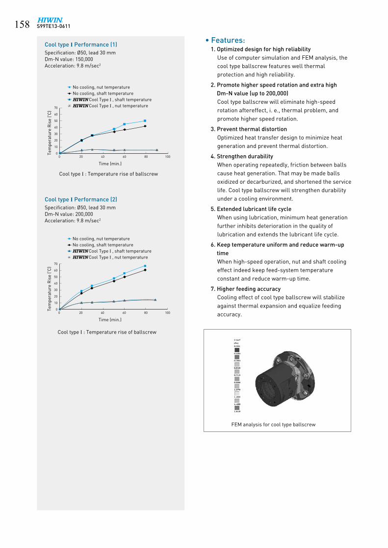
S99TE13-0611���
No cooling, nut temperatureNo cooling, shaft temperatureHIWIN Cool Type I , shaft temperatureHIWIN Cool Type I , nut temperature
Tem
pera
ture
Ris
e (° C
)
Time (min.)
70
60
50
40
30
20
10
00 20 40 60 80 100
Cool type I Performance (1)Specification: Ø50, lead 30 mmDm-N value: 150,000Acceleration: 9.8 m/sec2
No cooling, nut temperatureNo cooling, shaft temperatureHIWIN Cool Type I , shaft temperatureHIWIN Cool Type I , nut temperature
Tem
pera
ture
Ris
e (° C
)
Time (min.)
70
60
50
40
30
20
10
00 20 40 60 80 100
FEM analysis for cool type ballscrew
Cool type I Performance (2)Specification: Ø50, lead 30 mmDm-N value: 200,000Acceleration: 9.8 m/sec2
Cool type � : Temperature rise of ballscrew
Cool type � : Temperature rise of ballscrew
• Features:1. Optimized design for high reliability
Use of computer simulation and FEM analysis, thecool type ballscrew features well thermal protection and high reliability.
2. Promote higher speed rotation and extra high Dm-N value (up to 200,000)Cool type ballscrew will eliminate high-speed rotation aftereffect, i. e., thermal problem, and promote higher speed rotation.
3. Prevent thermal distortionOptimized heat transfer design to minimize heat generation and prevent thermal distortion.
4. Strengthen durabilityWhen operating repeatedly, friction between balls cause heat generation. That may be made balls oxidized or decarburized, and shortened the service life. Cool type ballscrew will strengthen durability under a cooling environment.
5. Extended lubricant life cycleWhen using lubrication, minimum heat generation further inhibits deterioration in the quality of lubrication and extends the lubricant life cycle.
6. Keep temperature uniform and reduce warm-up timeWhen high-speed operation, nut and shaft cooling effect indeed keep feed-system temperature constant and reduce warm-up time.
7. Higher feeding accuracy Cooling effect of cool type ballscrew will stabilize against thermal expansion and equalize feeding accuracy.

S99TE13-0611 ���9.5.2 High Load Ballcsrew - Cool Type II
• Cool type II : • New era for ballscrew applied in electric - driven injection machine, presses, power units, and
other replaceable hydraulic drives.• Electric-driven injection machine, presses, power units and other replaceable hydrauilc drives.
• Design Principle :The cool type series feature using forced cooling
fluid to pass through the nut, which minimize heat generation and thermal expansion during ballscrew operation.
• Cool type II as shown in the Figure 9.4:Flowing fluids are circulated through a space,
which inside the nut, and exchanging heat with the cooler as shown in the Figure 9.5. It is the most suitable for electric-driven injection machine, presses, and power units. The cool type ��, compared with the standard specifications, will make a minor external dimension change of the nut. Please contact HIWIN .
Germany Patent No. 20119457.0Taiwan Patent No. 193878
• Specification :1. We recommend shaft diameter above Ø32mm to cool type design.2. Nut type: FSV, FSW, PFDW, OFSW, DFSV, FSH, FSI, etc.3. Please contact HIWIN with other specification you need.4. The cool type ��, compared with the standard specifications, will make a minor external
dimension change of the nut, please contact HIWIN.
• Specification number:Example: R63 - 16B3 - RSWC2 - 400 - 600- 0.05
↓C2 : HIWIN cool type ballscrew for type ��
• Performance Comparison:
Test condition :specification : Ø50, lead 30 mm speed : 1500 rpm ( 45 m/min),
back and forth feed continuously acceleration : 4.9 m/sec2
stroke : 300 mmpreload : 205 kgfmoving weight : 300 kgf cooling rate : oil 2.5 liter/mininlet temperature : 16°Croom temperature : 25°CPT 1/8 fitting
Fig. 9.5 Cool type �� with cooler
Space
Cooler
P IN
OUT
Fig. 9.4 Cool type �� No cooling, nut temperatureNo cooling, shaft temperatureHIWIN Cool Type II , shaft temperatureHIWIN Cool Type II , nut temperature
Tem
pera
ture
Ris
e (° C
)
Time (min.)
50
40
30
20
10
00 20 40 60 80 120100
Fig. 9.6 Cool type �� : Temperature rise of ballscrew
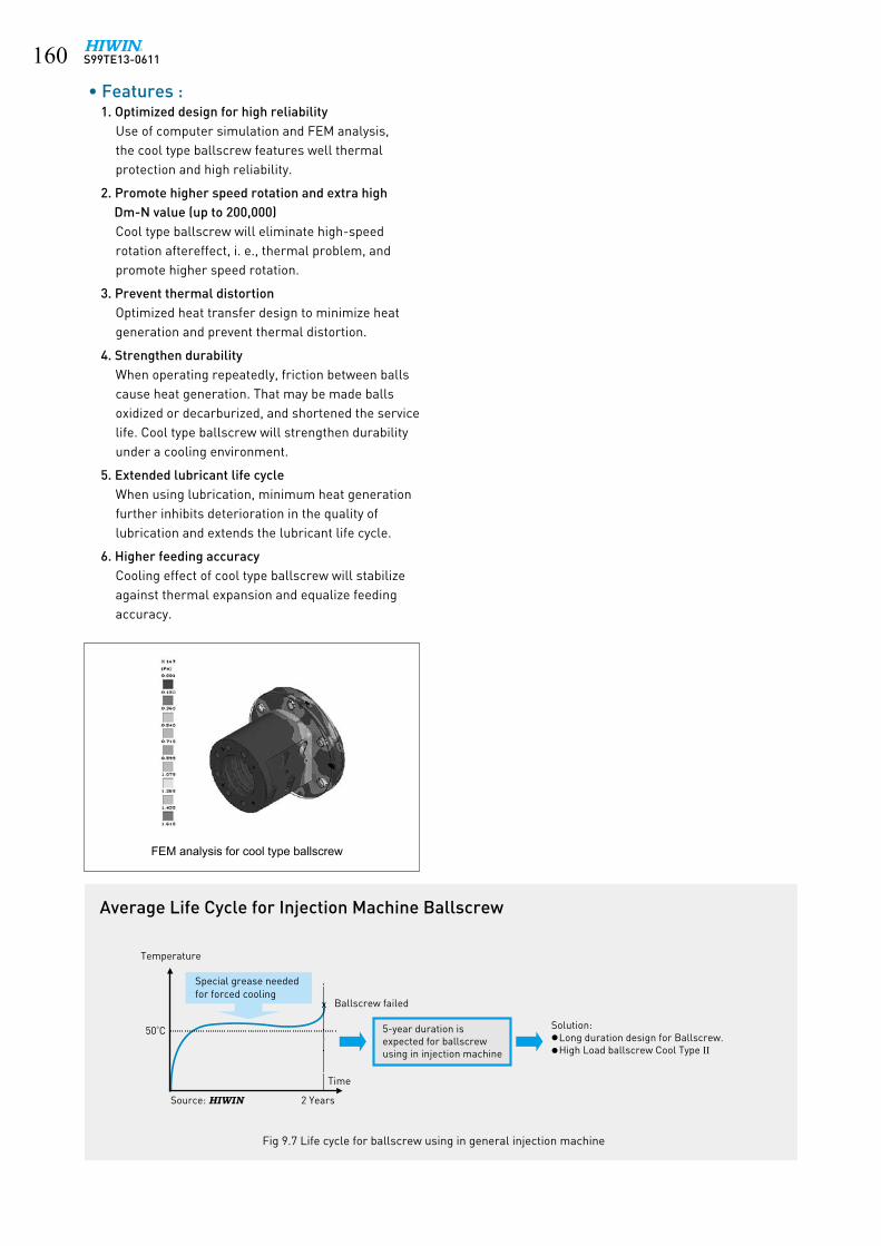
S99TE13-0611��0
Average Life Cycle for Injection Machine Ballscrew
x
Time
Source: HIWIN
Temperature
Special grease needed for forced cooling
Ballscrew failed
50°C 5-year duration is expected for ballscrewusing in injection machine
Solution: Long duration design for Ballscrew. High Load ballscrew Cool Type II
2 Years
FEM analysis for cool type ballscrew
Fig 9.7 Life cycle for ballscrew using in general injection machine
• Features :1. Optimized design for high reliability
Use of computer simulation and FEM analysis, the cool type ballscrew features well thermal protection and high reliability.
2. Promote higher speed rotation and extra high Dm-N value (up to 200,000)Cool type ballscrew will eliminate high-speed rotation aftereffect, i. e., thermal problem, and promote higher speed rotation.
3. Prevent thermal distortionOptimized heat transfer design to minimize heat generation and prevent thermal distortion.
4. Strengthen durabilityWhen operating repeatedly, friction between balls cause heat generation. That may be made balls oxidized or decarburized, and shortened the service life. Cool type ballscrew will strengthen durability under a cooling environment.
5. Extended lubricant life cycleWhen using lubrication, minimum heat generation further inhibits deterioration in the quality of lubrication and extends the lubricant life cycle.
6. Higher feeding accuracy Cooling effect of cool type ballscrew will stabilize against thermal expansion and equalize feeding accuracy.

S99TE13-0611 ���
9.6 Super S Series
• Application:CNC Machinery, Industrial Machinery, Electronic
Machinery, Precision Machine and other High Speed Machinery.
• Features :1. Low noise (5~7dB lower than traditional series)
The patent design of return unit can absorb noises caused by the impact of the ballnut’s balls, greatly reducing the noise intensity.
2. Space-saving and weight-lightening designThe ballnut diamenter is 18%~32% smaller than traditional series.
3. Dm-N value up to 220,000The patent design of the return unit can improve the strength of the return structure, achieving a Dm-N value of up to 220,000.
4. High acceleration and deceleration velocityThe pathway of specialized return unit, as well as the ballnut’s strengthened design diminish the impact experienced by the balls, Hence, it can sustain peak performance in more rigorous operating environments, such as high acceleration and deceleration.
5. Accuracy gradePrecision ground ballscrews available in JIS Grade C0~C7; Rolled ballscrews available in JIS Grade C6~C10.
• Pattern Nomenclature : Ex: R40-10K4 -FSC -1200 -1600 - 0.008
• Performance :Specification: 2R40 - 40K4 - DFSC - 1200 -1600 - 0.008Lead: 40 mmAcceleration: 1g (9.8m/sec2)Dm-N Value: 120,000
Cassette type Single nutNut with flange
4 turns
90
85
80
75
70
65
60
55
500 500 1000 1500 2000 2500 3000 3500
Speed (rpm)
65
60
55
50
45
40
35
30
25
200 2 4 6 8 10 12 14 16 18 20
dB
kHzAnalysis of noise frequency
Traditional SeriesSuper S Series
Traditional SeriesSuper S Series
Noi
se L
evel
dB
(A)
U.S.A. Patent No. 6561054Taiwan Patent No. 231845Taiwan Patent No. 233472Taiwan Patent No. 245857Taiwan Patent No. 115652Japan Patent No. 3117738

S99TE13-0611���
FSC TyPE
TYPE 1
22.5°
45 ° 45°
TYPE 2
30°
30 °
15° 15° 30°
D6
D4
D5
L10
MOIL HOLE
L7 L1L11
G
G
L2
d1
WIPER BOTH ENDSØF ØDg6 ØD-0.05-0.30
Form A
(D6)
Form B
L8
Form C
L9
Model
SizeBallDia.
CircuitsDynamic
LoadC(KN)
StaticLoad
Co(KN)
Nut Flange Oil Hole
NominalDia.
Lead D L1 L2 TYPEForm A
(D6)Form B
(L8)Form C
(L9)L7 D4 D5 M L10 L11
15-10K3 15 10 3.175 K3 960 1930 30 10 44 1 55 41 48 10 45 5.5 M6x1P 8 520-10K3
2010
3.175K3 1130 2660
3610 48
1 58 44 51 10 47 6.6 M6x1P 8 520-20K2 20 K2 760 1730 10 5725-10K3
2510
3.175K3 1260 3370
4010 51
162 48 55 10 51
6.6 M6x1P 8 525-25K2 15 K2 810 2170 10 7025-12K4 12 3.969 K4 2200 5640 43 10 68 65 51 58 10 5432-5K4
32
5 3.175 K4 1850 5970 48 10 38
1
70 55 62 12 59
9 M6x1P 8 6
32-8K5 83.969
K5 3080 946050
10 6380 62 71 12 6532-20K3 20 K3 1900 5430 20 88
32-32K2 32 K2 1280 3530 20 8832-10K5 10
4.763K5 3850 10890
5610 79
86 65 75.5 14 7132-12K5 12 K5 3840 10870 20 8932-10K5 10
6.35
K5 5640 14490
57
10 77
87 69 78 14 7232-12K5 12 K5 5620 14450 20 8732-16K4 16 K4 4570 11390 20 9032-20K4 20 K4 4530 11310 20 10736-10K5
36
10
6.35
K5 6010 16440
61
20 80
2 91 68 79.5 14 76 9 M8x1P 10 736-12K5 12 K5 5990 16420 20 8736-16K5 16 K5 5960 16350 20 10836-20K5 20 K5 5920 16270 20 12836-36K2 36 K2 2540 6540 20 9538-10K6
38
10
6.35
K6 7270 21060
63
20 90
2 93 70 81.5 14 73 9 M8x1P 10 7
38-12K6 12 K6 7260 21030 20 9938-16K5 16 K5 6140 17340 20 10838-20K5 20 K5 6100 17260 25 12838-25K4 25 K4 4940 13560 25 12638-40K2 40 K2 2590 6560 25 10240-10K6
40
10
6.35
K6 7270 21060
65
20 90
2 93 70 81.5 14 78 9 M8x1P 10 7
40-12K6 12 K6 7260 21030 20 9940-16K5 16 K5 6140 17340 20 10840-20K5 20 K5 6100 17260 25 12840-25K4 25 K4 4940 13560 25 10840-40K2 40 K2 2590 6560 25 10245-10K6
45
10
6.35
K6 8010 25760
70
20 90
2105 80 92.5
16 88 11 M8x1P 10 8
45-12K6 12 K6 8000 25730 20 10145-16K5 16 K5 6780 21240 20 10745-20K5 20 K5 6750 21170 25 12845-25K5 25 K5 6700 21060 25 15445-30K4 30 K4 5440 16570 25 15045-40K3 40 K3 4100 12020 25 14545-16K5 16
7.144K5 7810 23230
7420 119
109 84 96.545-20K5 20 K5 7770 23150 25 13950-10K6
50
10
6.35
K6 8290 28160
75
20 90
2 110 85 97.5 16 93 11 M8x1P 10 8
50-12K6 12 K6 8290 28130 20 10150-16K6 16 K6 8260 28070 20 12650-20K6 20 K6 8230 28000 25 14850-25K5 25 K5 6960 23070 25 15450-30K4 30 K4 5650 18170 25 14850-40K3 40 K3 4390 13750 25 145

S99TE13-0611 ���
FSC TyPE
TYPE 1
22.5°
45 ° 45°
TYPE 2
30°
30 °15° 15° 30°
D6
D4
D5
L10
MOIL HOLE
L7 L1L11
G
G
L2
d1
WIPER BOTH ENDSØF ØDg6 ØD-0.05-0.30
Form A
(D6)
Form B
L8
Form C
L9
ØD-0.05-0.30
Model
SizeBallDia.
CircuitsDynamic
LoadC(KN)
StaticLoad
Co(KN)
Nut Flange Oil Hole
NominalDia.
Lead D L1 L2 TYPEForm A
(D6)Form B
(L8)Form C
(L9)L7 D4 D5 M L10 L11
15-10K3 15 10 3.175 K3 960 1930 30 10 92 1 55 41 48 10 45 5.5 M6x1P 8 520-10K3
2010
3.175K3 1130 2660
3610 100
1 58 44 51 10 47 6.6 M6x1P 8 520-20K2 20 K2 760 1730 10 11825-10K3
2510
3.175K3 1260 3370
4010 106
162 48 55 10 51
6.6 M6x1P 8 525-25K2 15 K2 810 2170 10 14425-12K4 12 3.969 K4 2200 5640 43 10 140 65 51 58 10 5432-5K4
32
5 3.175 K4 1850 5970 48 10 80
1
70 55 62 12 59
9 M6x1P 8 6
32-8K5 83.969
K5 3080 946050
10 13080 62 71 12 6532-20K3 20 K3 1900 5430 20 180
32-32K2 32 K2 1280 3530 20 18032-10K5 10
4.763K5 3850 10890
5610 162
86 65 75.5 14 7132-12K5 12 K5 3840 10870 20 18232-10K5 10
6.35
K5 5640 14490
57
10 158
87 69 78 14 7232-12K5 12 K5 5620 14450 20 17832-16K4 16 K4 4570 11390 20 18432-20K4 20 K4 4530 11310 20 21836-10K5
36
10
6.35
K5 6010 16440
61
20 164
2 91 68 79.5 14 76 9 M8x1P 10 736-12K5 12 K5 5990 16420 20 17836-16K5 16 K5 5960 16350 20 22036-20K5 20 K5 5920 16270 20 26036-36K2 36 K2 2540 6540 20 19438-10K6
38
10
6.35
K6 7270 21060
63
20 184
2 93 70 81.5 14 78 9 M8x1P 10 7
38-12K6 12 K6 7260 21030 20 20238-16K5 16 K5 6140 17340 20 22038-20K5 20 K5 6100 17260 25 26038-25K4 25 K4 4940 13560 25 25638-40K2 40 K2 2590 6560 25 20840-10K6
40
10
6.35
K6 7270 21060
65
20 184
2 93 70 81.5 14 78 9 M8x1P 10 7
40-12K6 12 K6 7260 21030 20 20240-16K5 16 K5 6140 17340 20 22040-20K5 20 K5 6100 17260 25 26040-25K4 25 K4 4940 13560 25 25640-40K2 40 K2 2590 6560 25 20845-10K6
45
10
6.35
K6 8010 25760
70
20 184
2105 80 92.5
16 88 11 M8x1P 10 8
45-12K6 12 K6 8000 25730 20 20645-16K5 16 K5 6780 21240 20 21845-20K5 20 K5 6750 21170 25 26045-25K5 25 K5 6700 21060 25 31245-30K4 30 K4 5440 16570 25 34045-40K3 40 K3 4100 12020 25 29445-16K5 16
7.144K5 7810 23230
7420 242
109 84 96.545-20K5 20 K5 7770 23150 25 28250-10K6
50
10
6.35
K6 8290 28160
75
20 184
2 110 85 97.5 16 93 11 M8x1P 10 8
50-12K6 12 K6 8290 28130 20 20650-16K6 16 K6 8260 28070 20 25650-20K6 20 K6 8230 28000 25 30050-25K5 25 K5 6960 23070 25 31250-30K4 30 K4 5650 18170 25 30050-40K3 40 K3 4390 13750 25 294